https://support.industry.siemens.com/cs/ww/en/view/109743917 Application description 11/2016 Position Control with S7-1200 and SINAMICS V90 PN (S mode) SINAMICS V90 Profinet Version

Welcome message from author
This document is posted to help you gain knowledge. Please leave a comment to let me know what you think about it! Share it to your friends and learn new things together.
Transcript
https://support.industry.siemens.com/cs/ww/en/view/109743917
Application description 11/2016
Position Control with S7-1200 and SINAMICS V90 PN (S mode) SINAMICS V90 Profinet Version

Warranty and liability
Position Control with S7-1200 and V90 via IRT Profinet Entry-ID: 109743917, V1.0, 11/2016 2
S
iem
en
s A
G 2
01
6 A
ll ri
gh
ts r
ese
rve
d
Warranty and liability
Note The Application Examples are not binding and do not claim to be complete regarding the circuits shown, equipping and any eventuality. The Application Examples do not represent customer-specific solutions. They are only intended to provide support for typical applications. You are responsible for ensuring that the described products are used correctly. These Application Examples do not relieve you of the responsibility to use safe practices in application, installation, operation and maintenance. When using these Application Examples, you recognize that we cannot be made liable for any damage/claims beyond the liability clause described. We reserve the right to make changes to these Application Examples at any time without prior notice. If there are any deviations between the recommendations provided in these Application Examples and other Siemens publications – e.g. Catalogs – the contents of the other documents have priority.
We do not accept any liability for the information contained in this document. Any claims against us – based on whatever legal reason – resulting from the use of the examples, information, programs, engineering and performance data etc., described in this Application Example shall be excluded. Such an exclusion shall not apply in the case of mandatory liability, e.g. under the German Product Liability Act (“Produkthaftungsgesetz”), in case of intent, gross negligence, or injury of life, body or health, guarantee for the quality of a product, fraudulent concealment of a deficiency or breach of a condition which goes to the root of the contract (“wesentliche Vertragspflichten”). The damages for a breach of a substantial contractual obligation are, however, limited to the foreseeable damage, typical for the type of contract, except in the event of intent or gross negligence or injury to life, body or health. The above provisions do not imply a change of the burden of proof to your detriment. Any form of duplication or distribution of these Application Examples or excerpts hereof is prohibited without the expressed consent of the Siemens AG.
Security informa-tion
Siemens provides products and solutions with industrial security functions that support the secure operation of plants, systems, machines and networks. In order to protect plants, systems, machines and networks against cyber threats, it is necessary to implement – and continuously maintain – a holistic, state-of-the-art industrial security concept. Siemens’ products and solutions only form one element of such a concept. Customer is responsible to prevent unauthorized access to its plants, systems, machines and networks. Systems, machines and components should only be connected to the enterprise network or the internet if and to the extent necessary and with appropriate security measures (e.g. use of firewalls and network segmentation) in place. Additionally, Siemens’ guidance on appropriate security measures should be taken into account. For more information about industrial security, please visit http://www.siemens.com/industrialsecurity.
Siemens’ products and solutions undergo continuous development to make them more secure. Siemens strongly recommends to apply product updates as soon as available and to always use the latest product versions. Use of product versions that are no longer supported, and failure to apply latest updates may increase customer’s exposure to cyber threats. To stay informed about product updates, subscribe to the Siemens Industrial Security RSS Feed under http://www.siemens.com/industrialsecurity.
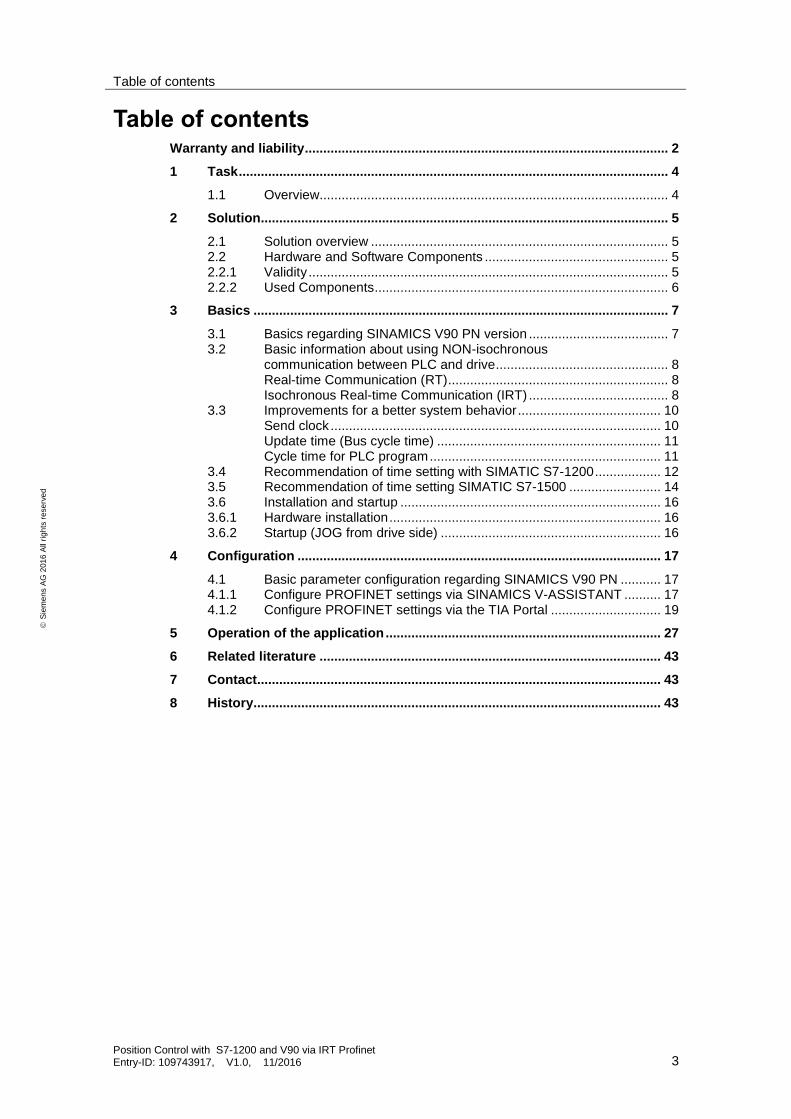
Table of contents
Position Control with S7-1200 and V90 via IRT Profinet Entry-ID: 109743917, V1.0, 11/2016 3
S
iem
en
s A
G 2
01
6 A
ll ri
gh
ts r
ese
rve
d
Table of contents Warranty and liability ................................................................................................... 2
1 Task ..................................................................................................................... 4
1.1 Overview............................................................................................... 4
2 Solution............................................................................................................... 5
2.1 Solution overview ................................................................................. 5 2.2 Hardware and Software Components .................................................. 5 2.2.1 Validity .................................................................................................. 5 2.2.2 Used Components ................................................................................ 6
3 Basics ................................................................................................................. 7
3.1 Basics regarding SINAMICS V90 PN version ...................................... 7 3.2 Basic information about using NON-isochronous
communication between PLC and drive ............................................... 8 Real-time Communication (RT) ............................................................ 8 Isochronous Real-time Communication (IRT) ...................................... 8
3.3 Improvements for a better system behavior ....................................... 10 Send clock .......................................................................................... 10 Update time (Bus cycle time) ............................................................. 11 Cycle time for PLC program ............................................................... 11
3.4 Recommendation of time setting with SIMATIC S7-1200 .................. 12 3.5 Recommendation of time setting SIMATIC S7-1500 ......................... 14 3.6 Installation and startup ....................................................................... 16 3.6.1 Hardware installation .......................................................................... 16 3.6.2 Startup (JOG from drive side) ............................................................ 16
4 Configuration ................................................................................................... 17
4.1 Basic parameter configuration regarding SINAMICS V90 PN ........... 17 4.1.1 Configure PROFINET settings via SINAMICS V-ASSISTANT .......... 17 4.1.2 Configure PROFINET settings via the TIA Portal .............................. 19
5 Operation of the application ........................................................................... 27
6 Related literature ............................................................................................. 43
7 Contact.............................................................................................................. 43
8 History............................................................................................................... 43
1 Task
Position Control with S7-1200 and V90 via IRT Profinet Entry-ID: 109743917, V1.0, 11/2016 4
S
iem
en
s A
G 2
01
6 A
ll ri
gh
ts r
ese
rve
d
1 Task
1.1 Overview
Introduction
In this manual the basic application “Position control with a S7-1200 and SINAMICS V90 PN” will be described in detail.
The SINAMICS V90 PN works in this application in speed control mode (S mode) and the communication will use PROFINET RT.
The described solution in this document contains the variations which have some detailed technical issues to look at it.
Overview of the automation task
The figure below provides an overview of the automation task.
Figure 1-1
SIMATIC PLC
Servo Drive Servo Motor
PC/PG
Profinet cable
Encoder cable
Power cable

2 Solution
Position Control with S7-1200 and V90 via IRT Profinet Entry-ID: 109743917, V1.0, 11/2016 5
S
iem
en
s A
G 2
01
6 A
ll ri
gh
ts r
ese
rve
d
2 Solution
2.1 Solution overview
Schema Display
The following figure displays the most important components of the solution:
Figure 2-1
IO device
IO Supervisor
IO controller
Delimitation
This application does not include a description of
Profinet communication
SINAMICS V90 PN version
BOP operation of SINAMICS V90
Basic knowledge of these topics is assumed.
Required knowledge
Basic knowledge on TIA Portal is assumed.
2.2 Hardware and Software Components
2.2.1 Validity
This application example is valid for
TIA Portal V13 or newer
S7-1200 CPU with PN interface
SINAMICS V90 PN FW V10001.0 or newer
SIMOTICS S-1FL6 Li motor

2 Solution
Position Control with S7-1200 and V90 via IRT Profinet Entry-ID: 109743917, V1.0, 11/2016 6
S
iem
en
s A
G 2
01
6 A
ll ri
gh
ts r
ese
rve
d
2.2.2 Used Components
The application was generated with the following components:
Hardware components
Table 2-1
Component No. Article number Note
SIMATIC S7-1200 1217C DC/DC/DC
1 6ES7217-1AG40-0XB0 V4.1
SINAMICS V90 PN 200V 1 6SL3210-5FB10-4UF0 400W
SIMOTICS S-1FL6 Li motor
1 1FL6034-2AF21-1AG1 400W
Standard software components
Table 2-2
Component No. Article number Note
TIA Portal 1 V13
SINAMICS V-ASSISTANT 1 V1.04.00
Sample files and projects
The following list includes all files and projects that are used in this example.
Table 2-3
Component Note
109743917_CPU1217C + V90 PN for Position Control Project file
Standard Application_v90pn_S7_1200_PositionControl.docx Reference document
3 Basics
Position Control with S7-1200 and V90 via IRT Profinet Entry-ID: 109743917, V1.0, 11/2016 7
S
iem
en
s A
G 2
01
6 A
ll ri
gh
ts r
ese
rve
d
3 Basics
3.1 Basics regarding SINAMICS V90 PN version
When SINAMICS V90 PN works in the speed control mode (S mode), the following telegrams are supported:
Standard telegram 1
Standard telegram 2
Standard telegram 3
Standard telegram 5
Siemens telegram 102
Siemens telegram 105
NOTE Siemens telegram 105 is only available with TIA Portal V14, the Hardware Support Package for V90PN for TIA Portal and in combination with S7-1500 / 1500T.
The standard telegram 1 can be used only for RT mode. The standard telegram 2, the standard telegram 3 and the standard telegram 102 can be used either for RT mode or IRT mode depending on the IO controller. The standard telegram 5 and the standard telegram 105 can only support IRT mode and be used with TIA Portal V14.
The telegrams 1, 2 and 102 are used for speed control axis while telegrams 3, 5 and 105 are used for positioning axis because these telegrams contain the actual position of the encoder (Gn_XIST1).
If SIMATIC S7-1200 is used for positioning control then the TO (Technology Object) Positioning axis has to be used. The TO Positioning axis only supports the standard telegrams 1, 2 and 3. Thus, the standard telegram 3 will be used in this basic application.

3 Basics
Position Control with S7-1200 and V90 via IRT Profinet Entry-ID: 109743917, V1.0, 11/2016 8
S
iem
en
s A
G 2
01
6 A
ll ri
gh
ts r
ese
rve
d
3.2 Basic information about using NON-isochronous communication between PLC and drive
PROFINET IO is a scalable real-time communication system based on the Layer 2 protocol for Fast Ethernet. With the RT transmission method, two real-time-support performance levels are available for time-critical process data and IRT for high accuracy and also isochronous processes.
Figure 3-1
PROFINET with IRT
(Isochronous Real-Time)
PROFINET with RT
(Real-Time)
Dete
rmin
istics
Real-time Communication (RT)
PROFINET IO with real-time communication (RT) is the ideal solution for integrating IO systems. This is a solution that also uses standard Ethernet in the devices and commercially available industrial switches as infrastructure components. A special hardware support is not required.
PROFINET IO frames have priority over standard frames in accordance with IEEE802.1Q. This ensures the required determinism in the automation technology. The data is transferred via prioritized Ethernet frames.
With RT, you can achieve update times ≥ 250 μs with RT.
NOTE SIMATIC S7-1200 works only with RT communication.
Isochronous Real-time Communication (IRT)
IRT is a synchronized communication protocol for cyclic exchange of IRT data between PROFINET devices. A reserved bandwidth is available in the send cycle for IRT data. The reserved bandwidth ensures that the IRT data can be transferred at reserved synchronized intervals, without being influenced also by higher other network loads (such as TCP/IP communication, or additional real-time communication).
Topology configuration is a prerequisite for IRT.
In addition to the reserved bandwidth, the telegrams from defined transmission paths are exchanged for the further optimization of data transfers. For this, the topological information from the configuration is used for planning the communication. Thus, transmission and reception points of every individual data telegram at every communication node are guaranteed. This allows you to achieve

3 Basics
Position Control with S7-1200 and V90 via IRT Profinet Entry-ID: 109743917, V1.0, 11/2016 9
S
iem
en
s A
G 2
01
6 A
ll ri
gh
ts r
ese
rve
d
optimal usage of the bandwidth and reach the best possible performance in the PROFINET IO system.
Use of IRT allows you to achieve update times with highest deterministics ≥ 250 µs
and a jitter accuracy of the send clock < 1 µs. Isochronous applications are possible with IRT.
Fields of application
Table 3-1 Fields of application for RT and IRT
RT IRT
Time-critical applications in factory automation
The implementation of large quantity structures in line process plants
Considerable deterministics with large quantity structures concerning the I/O user data communication (productive data)
Considerable performance also with many devices concerning the I/O user data communication (productive data)
Parallel transfer of productive and TCP/IP data via a cable, even with considerable data
traffic whilst ensuring the forwarding of productive data by reserving the transmission bandwidth
The major differences between RT and IRT
Table 3-2 Comparison between RT and IRT
Property RT IRT
Transmission method Prioritizing the RT frames through Ethernet priority (VLAN tag)
Path-based switching on the basis of a communication path plan; no transmission of TCP/IP frames in the time range with IRT communication.
Determinism Variance of the duration of transmission by the shared use of the transmission band-width with other protocols (e.g., TCP/IP)
Exact, planned transmission, transmission and reception times are guaranteed for all topologies.
Hardware support through special Ethernet controllers is required
Not required Required
Isochronous application Yes (only for the integrated PROFINET IO interface of the CPU)
Starting time of the isochronous application
The point in time for the reception of the data is planned exactly. Application can be started synchronized to the cycle.

3 Basics
Position Control with S7-1200 and V90 via IRT Profinet Entry-ID: 109743917, V1.0, 11/2016 10
S
iem
en
s A
G 2
01
6 A
ll ri
gh
ts r
ese
rve
d
3.3 Improvements for a better system behavior
Figure 3-2 Communication cycle
Send clock 1 Send clock 2 Send clock 3 Send clock 4
“n-1” “n+1”Bus cycle time
Send clock
Send clock is the shortest possible time interval in data exchange.
The calculation of send clock should follow the formula below:
Send clock = 31.25 μs * Send Clock Factor
The send clock factor is 2n (n is an integral value from 0 to 9), while 31.25 μs is the
basic time unit.
Figure 3-3 Send clock in TIA Portal (follow step 1 to 2 to do the change of send clock)
NOTE The send clock is unable to be changed for RT communication.

3 Basics
Position Control with S7-1200 and V90 via IRT Profinet Entry-ID: 109743917, V1.0, 11/2016 11
S
iem
en
s A
G 2
01
6 A
ll ri
gh
ts r
ese
rve
d
Update time (Bus cycle time)
The update time is a time interval. IO controller and IO device/I-device exchange IO data cyclically in the IO system within this time interval. The update time can be configured separately for each IO device and determines the interval at which output data is sent from the IO controller to the IO device (output module/submodule) as well as input data from the IO device to the IO controller (input module/submodule).
STEP 7 calculates the update time automatically in the default setting for each IO device of the PROFINET IO system, taking into account the volume of data to be exchanged as well as the set send clock.
The calculation of update time should follow the formula below:
Update time = 31.25 μs * Send Clock Factor * 2n = Send clock * 2
n
2n: reduction (an integral value ≤ 16), n: reduction ratio
Figure 3-4 update time (bus cycle time) in TIA Portal (follow step 1 to 3 to change the bus cycle time)
Cycle time for PLC program
Cycle time of PLC program is also calculated automatically within STEP 7. It can be changed according to actual application.
The relationship between cycle time for PLC program and bus cycle time as well as send clock (cycle n) is shown as follows:
Figure 3-5 Cycle communication
Cycle 1 Cycle 2 Cycle …
T1: cycle time for PLC program T2: Bus cycle time

3 Basics
Position Control with S7-1200 and V90 via IRT Profinet Entry-ID: 109743917, V1.0, 11/2016 12
S
iem
en
s A
G 2
01
6 A
ll ri
gh
ts r
ese
rve
d
3.4 Recommendation of time setting with SIMATIC S7-1200
NOTICE Mechanical disturbance caused by unfavorable cycle times!
Unexpected mechanical disturbances can be caused by current and torque disturbances.
NOTE When SINAMICS V90 PN works in RT communication, the minimum cycle time is unchangeable and fixed to be 4 ms.
When SIMATIC S7-1200 is connected to SINAMICS V90 PN for positioning control, OB91 (MC-Servo) must be used. The cycle time for OB91 can be changed according to actual application requirements.
Usually, the following rules during the configuration of OB91 cycle time and bus cycle time must be observed:
The ratio between OB91 cycle time and Bus cycle time or vice versa must be an even integral value
The CPU capability must be considered
Following selections of bus cycle time are recommended according to our test:
Table 3-3 Recommended Bus cycle time (in ms) for SIMATIC S7-1200
OB91 cycle time Bus cycle time (IO cycle) Min. cycle time in V90 PN
2 1 4
4 1 4
8 1 4
12 1 4
16 1 4
2 2 4
4 2 4
8 2 4
12 2 4
16 2 4
2 4 4
4 4 4
8 4 4
16 4 4
3 Basics
Position Control with S7-1200 and V90 via IRT Profinet Entry-ID: 109743917, V1.0, 11/2016 13
S
iem
en
s A
G 2
01
6 A
ll ri
gh
ts r
ese
rve
d
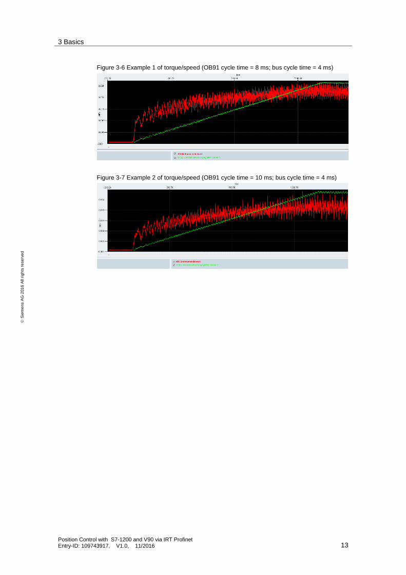
Figure 3-6 Example 1 of torque/speed (OB91 cycle time = 8 ms; bus cycle time = 4 ms)
Figure 3-7 Example 2 of torque/speed (OB91 cycle time = 10 ms; bus cycle time = 4 ms)
3 Basics
Position Control with S7-1200 and V90 via IRT Profinet Entry-ID: 109743917, V1.0, 11/2016 14
S
iem
en
s A
G 2
01
6 A
ll ri
gh
ts r
ese
rve
d
3.5 Recommendation of time setting SIMATIC S7-1500
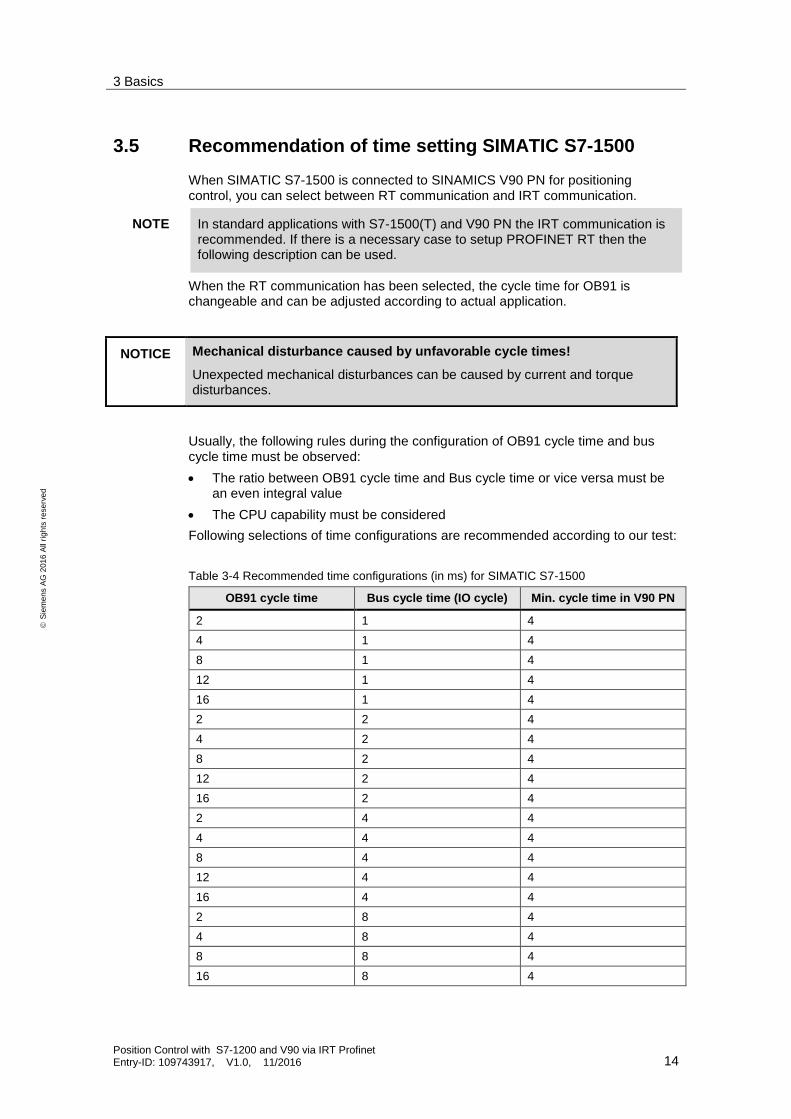
When SIMATIC S7-1500 is connected to SINAMICS V90 PN for positioning control, you can select between RT communication and IRT communication.
NOTE In standard applications with S7-1500(T) and V90 PN the IRT communication is recommended. If there is a necessary case to setup PROFINET RT then the following description can be used.
When the RT communication has been selected, the cycle time for OB91 is changeable and can be adjusted according to actual application.
Usually, the following rules during the configuration of OB91 cycle time and bus cycle time must be observed:
The ratio between OB91 cycle time and Bus cycle time or vice versa must be an even integral value
The CPU capability must be considered
Following selections of time configurations are recommended according to our test:
Table 3-4 Recommended time configurations (in ms) for SIMATIC S7-1500
OB91 cycle time Bus cycle time (IO cycle) Min. cycle time in V90 PN
2 1 4
4 1 4
8 1 4
12 1 4
16 1 4
2 2 4
4 2 4
8 2 4
12 2 4
16 2 4
2 4 4
4 4 4
8 4 4
12 4 4
16 4 4
2 8 4
4 8 4
8 8 4
16 8 4
NOTICE Mechanical disturbance caused by unfavorable cycle times!
Unexpected mechanical disturbances can be caused by current and torque disturbances.

3 Basics
Position Control with S7-1200 and V90 via IRT Profinet Entry-ID: 109743917, V1.0, 11/2016 15
S
iem
en
s A
G 2
01
6 A
ll ri
gh
ts r
ese
rve
d
Figure 3-8 Example 1 of torque/speed (OB91 cycle time = 4 ms; bus cycle time = 2 ms)
Figure 3-9 Example 2 of torque/speed (OB91 cycle time = 4 ms; bus cycle time = 3 ms)
NOTICE Mechanical disturbance caused by unfavorable cycle times!
Unexpected mechanical disturbances can be caused by current and torque disturbances.

3 Basics
Position Control with S7-1200 and V90 via IRT Profinet Entry-ID: 109743917, V1.0, 11/2016 16
S
iem
en
s A
G 2
01
6 A
ll ri
gh
ts r
ese
rve
d
3.6 Installation and startup
3.6.1 Hardware installation
The figure below shows the hardware configuration of the application:
CAUTION Wrong wiring can damage the drive!
In this application, the one phase 230V power supply is used. It is a must for you to check the supply voltage; otherwise, the drive can be damaged!
Figure 3-1 L
N
PE
M
L1 L2 PE
U V W Port2 Port1
24V+ 0V PE
SINAMICS V90 PN
1-phase230V
L1 N PE SIMATIC S7-1200
CPU 1217CX1P1 X1P2
3.6.2 Startup (JOG from drive side)
Table 3-1
Nr. Action Remarks
1. Set drive parameter p29108 to be 1. JOG function is enabled when p29108=1
2. Switch to JOG menu with drive BOP operation.
3. Press or button to run the motor.
4.
4 Configuration
Position Control with S7-1200 and V90 via IRT Profinet Entry-ID: 109743917, V1.0, 11/2016 17
S
iem
en
s A
G 2
01
6 A
ll ri
gh
ts r
ese
rve
d
4 Configuration In this chapter the configurations for position control with RT mode will be described in detail. The used standard telegram is “3”.
4.1 Basic parameter configuration regarding SINAMICS V90 PN
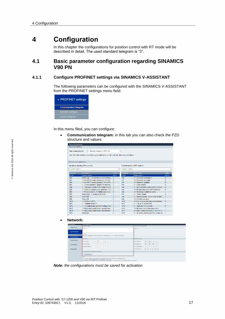
4.1.1 Configure PROFINET settings via SINAMICS V-ASSISTANT
The following parameters can be configured with the SINAMICS V-ASSISTANT from the PROFINET settings menu field:
In this menu filed, you can configure:
Communication telegram: in this tab you can also check the PZD structure and values:
Network:
Note: the configurations must be saved for activation.
4 Configuration
Position Control with S7-1200 and V90 via IRT Profinet Entry-ID: 109743917, V1.0, 11/2016 18
S
iem
en
s A
G 2
01
6 A
ll ri
gh
ts r
ese
rve
d
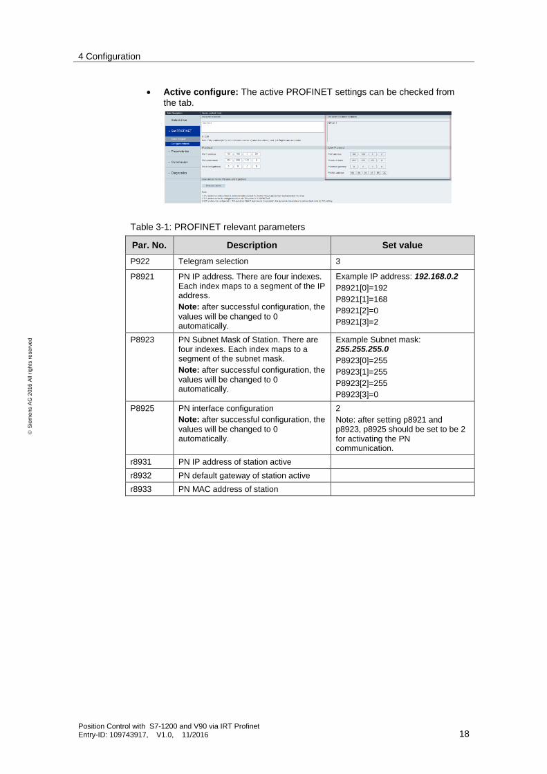
Active configure: The active PROFINET settings can be checked from
the tab.
Table 3-1: PROFINET relevant parameters
Par. No. Description Set value
P922 Telegram selection 3
P8921 PN IP address. There are four indexes. Each index maps to a segment of the IP address.
Note: after successful configuration, the
values will be changed to 0 automatically.
Example IP address: 192.168.0.2
P8921[0]=192
P8921[1]=168
P8921[2]=0
P8921[3]=2
P8923 PN Subnet Mask of Station. There are four indexes. Each index maps to a segment of the subnet mask.
Note: after successful configuration, the
values will be changed to 0 automatically.
Example Subnet mask: 255.255.255.0
P8923[0]=255
P8923[1]=255
P8923[2]=255
P8923[3]=0
P8925 PN interface configuration
Note: after successful configuration, the
values will be changed to 0 automatically.
2
Note: after setting p8921 and p8923, p8925 should be set to be 2 for activating the PN communication.
r8931 PN IP address of station active
r8932 PN default gateway of station active
r8933 PN MAC address of station

4 Configuration
Position Control with S7-1200 and V90 via IRT Profinet Entry-ID: 109743917, V1.0, 11/2016 19
S
iem
en
s A
G 2
01
6 A
ll ri
gh
ts r
ese
rve
d
4.1.2 Configure PROFINET settings via the TIA Portal
4.1.2.1 Create a new project
1. Open the TIA Portal and create a new project:
2. Switch to “Project view”:
4 Configuration
Position Control with S7-1200 and V90 via IRT Profinet Entry-ID: 109743917, V1.0, 11/2016 20
S
iem
en
s A
G 2
01
6 A
ll ri
gh
ts r
ese
rve
d
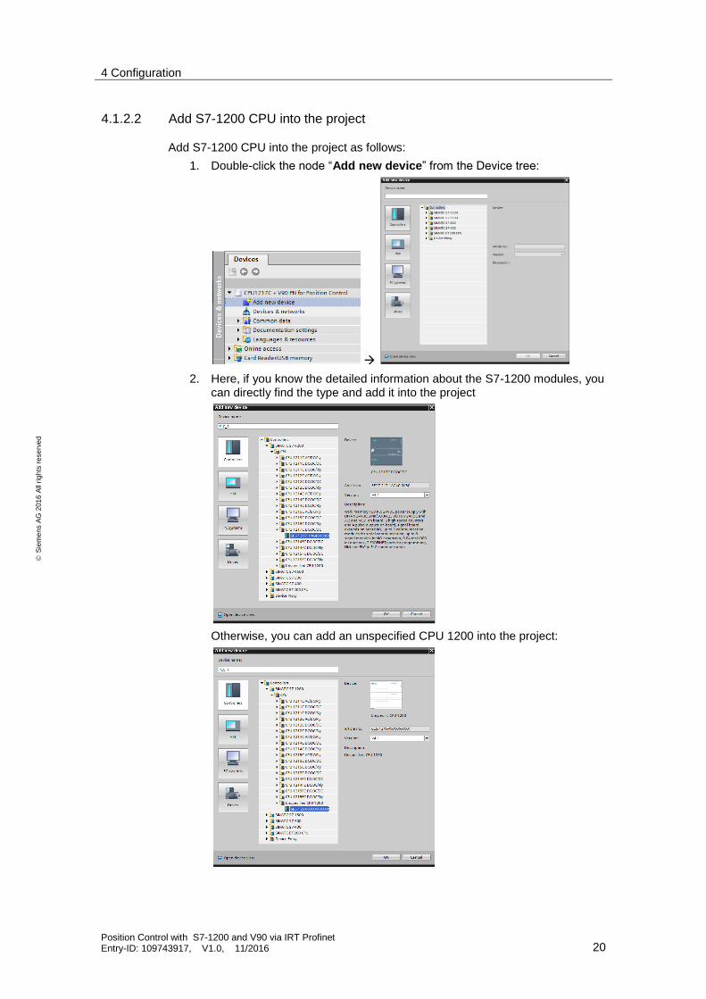
4.1.2.2 Add S7-1200 CPU into the project
Add S7-1200 CPU into the project as follows:
1. Double-click the node “Add new device” from the Device tree:
2. Here, if you know the detailed information about the S7-1200 modules, you can directly find the type and add it into the project
Otherwise, you can add an unspecified CPU 1200 into the project:
4 Configuration
Position Control with S7-1200 and V90 via IRT Profinet Entry-ID: 109743917, V1.0, 11/2016 21
S
iem
en
s A
G 2
01
6 A
ll ri
gh
ts r
ese
rve
d
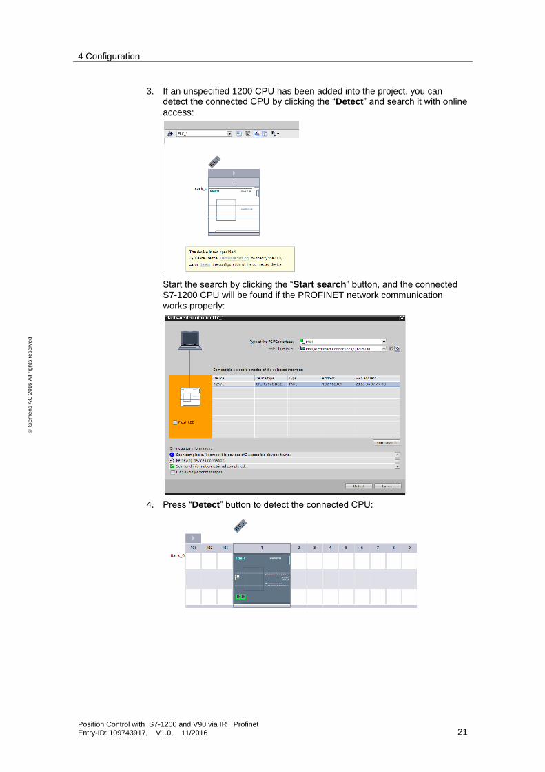
3. If an unspecified 1200 CPU has been added into the project, you can detect the connected CPU by clicking the “Detect” and search it with online
access:
Start the search by clicking the “Start search” button, and the connected S7-1200 CPU will be found if the PROFINET network communication works properly:
4. Press “Detect” button to detect the connected CPU:

4 Configuration
Position Control with S7-1200 and V90 via IRT Profinet Entry-ID: 109743917, V1.0, 11/2016 22
S
iem
en
s A
G 2
01
6 A
ll ri
gh
ts r
ese
rve
d
4.1.2.3 Add SINAMICS V90 PN into the project
Add SINAMICS V90 PN into the project in the TIA Portal as follows:
1. Input the V90 PN GSD file.
NOTE Installation of V90 PN GSD file is only necessary for TIA Portal prior to V14 (not including V14).
For the GSD file, you can download from following internet site:
https://support.industry.siemens.com/cs/document/109737269/sinamics-v90%3A-profinet-gsd-file?dti=0&pnid=13211&lc=en-WW
2. Find the GSD file and select it. Press the “Install” button to install it.
3. In the network view, select V90 PN from the “other filed drives” of catalog tree on the right side.

4 Configuration
Position Control with S7-1200 and V90 via IRT Profinet Entry-ID: 109743917, V1.0, 11/2016 23
S
iem
en
s A
G 2
01
6 A
ll ri
gh
ts r
ese
rve
d
4. Double-click the V90 PN node or drag it to the network view:
4 Configuration
Position Control with S7-1200 and V90 via IRT Profinet Entry-ID: 109743917, V1.0, 11/2016 24
S
iem
en
s A
G 2
01
6 A
ll ri
gh
ts r
ese
rve
d
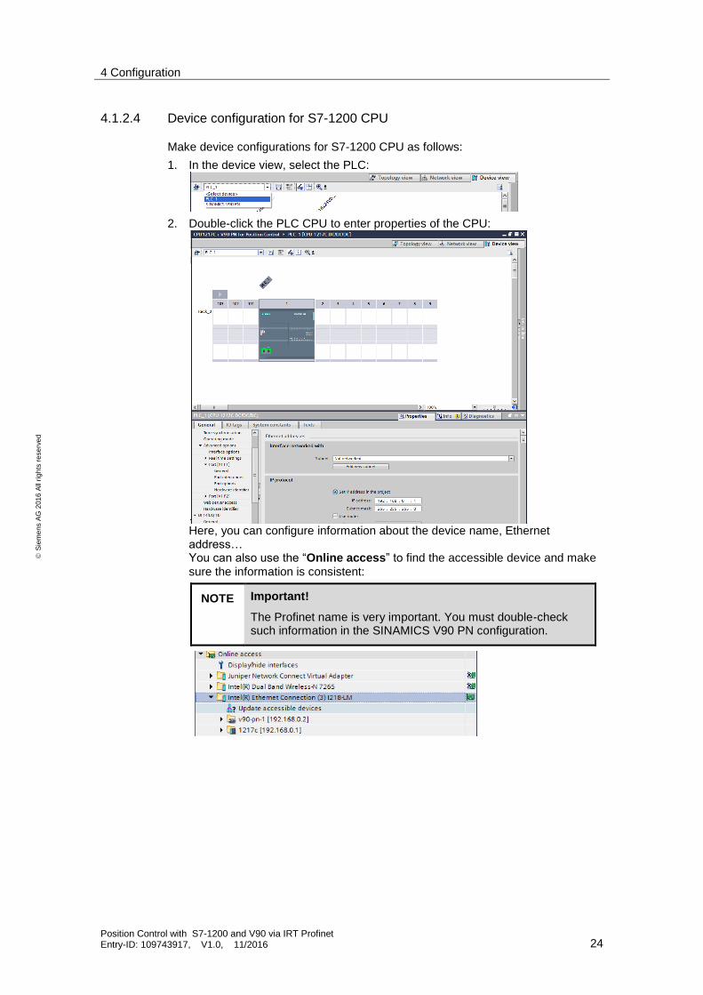
4.1.2.4 Device configuration for S7-1200 CPU
Make device configurations for S7-1200 CPU as follows:
1. In the device view, select the PLC:
2. Double-click the PLC CPU to enter properties of the CPU:
Here, you can configure information about the device name, Ethernet address… You can also use the “Online access” to find the accessible device and make
sure the information is consistent:
NOTE Important!
The Profinet name is very important. You must double-check such information in the SINAMICS V90 PN configuration.

4 Configuration
Position Control with S7-1200 and V90 via IRT Profinet Entry-ID: 109743917, V1.0, 11/2016 25
S
iem
en
s A
G 2
01
6 A
ll ri
gh
ts r
ese
rve
d
4.1.2.5 Device configuration for SINAMICS V90 PN
Make device configurations for S7-1200 CPU as follows:
1. In the device view, select the SINAMICS V90 PN:
2. Double-click the V90 PN to enter the properties field:
Here, you can configure information about the device name, Ethernet address… You can also use the “Online access” to find the accessible device and make sure the information is consistent:
NOTE Important!
The Profinet name is very important. You must double-check such information in the SINAMICS V90 PN configuration.
3. In the device view of SINAMICS V90 PN, select the standard telegram 3 from the submodules:
4 Configuration
Position Control with S7-1200 and V90 via IRT Profinet Entry-ID: 109743917, V1.0, 11/2016 26
S
iem
en
s A
G 2
01
6 A
ll ri
gh
ts r
ese
rve
d
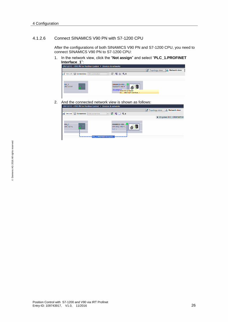
4.1.2.6 Connect SINAMICS V90 PN with S7-1200 CPU
After the configurations of both SINAMICS V90 PN and S7-1200 CPU, you need to connect SINAMICS V90 PN to S7-1200 CPU:
1. In the network view, click the “Not assign” and select “PLC_1.PROFINET Interface_1”:
2. And the connected network view is shown as follows:

5 Operation of the application
Position Control with S7-1200 and V90 via IRT Profinet Entry-ID: 109743917, V1.0, 11/2016 27
S
iem
en
s A
G 2
01
6 A
ll ri
gh
ts r
ese
rve
d
5 Operation of the application In the following paragraph, we will use TO (Technology Object) of positioning axis for programming and run the motor:
1. Add a new object by double-click “Add new object” from the project tree:
Figure 5-1
5 Operation of the application
Position Control with S7-1200 and V90 via IRT Profinet Entry-ID: 109743917, V1.0, 11/2016 28
S
iem
en
s A
G 2
01
6 A
ll ri
gh
ts r
ese
rve
d
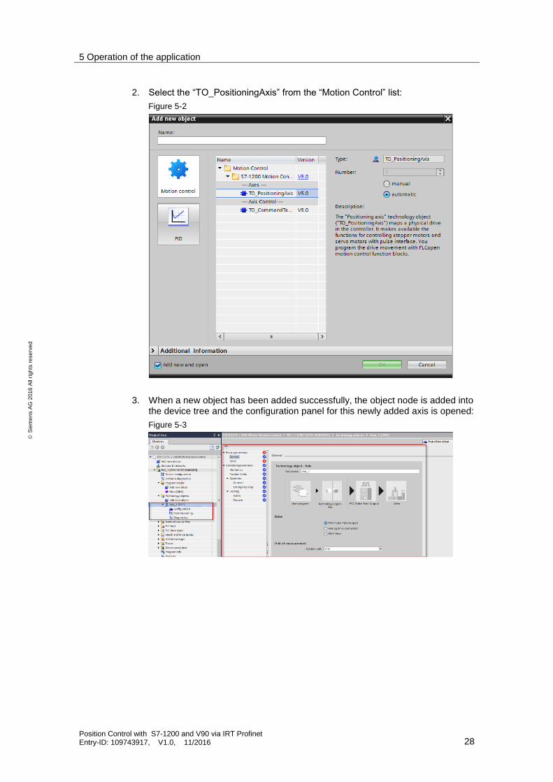
2. Select the “TO_PositioningAxis” from the “Motion Control” list:
Figure 5-2
3. When a new object has been added successfully, the object node is added into the device tree and the configuration panel for this newly added axis is opened:
Figure 5-3

5 Operation of the application
Position Control with S7-1200 and V90 via IRT Profinet Entry-ID: 109743917, V1.0, 11/2016 29
S
iem
en
s A
G 2
01
6 A
ll ri
gh
ts r
ese
rve
d
4. Make configurations step by step. In this example, we firstly need to configure the type of drive to be “PROFIdrive” under general information of basic parameters:
Figure 5-4
5. After configuring the type of drive, we need to select a PROFIdrive in the drive information of basic parameters:
Figure 5-5

5 Operation of the application
Position Control with S7-1200 and V90 via IRT Profinet Entry-ID: 109743917, V1.0, 11/2016 30
S
iem
en
s A
G 2
01
6 A
ll ri
gh
ts r
ese
rve
d
6. After that, change the steps per revolution to 2500 because an incremental encoder with the resolution of 2500 ppr is used in our example:
Figure 5-6

5 Operation of the application
Position Control with S7-1200 and V90 via IRT Profinet Entry-ID: 109743917, V1.0, 11/2016 31
S
iem
en
s A
G 2
01
6 A
ll ri
gh
ts r
ese
rve
d
7. Select encoder coupling under the encoder information of the basic parameters. In this example, it should be “Encoder on drive”:
Figure 5-7

5 Operation of the application
Position Control with S7-1200 and V90 via IRT Profinet Entry-ID: 109743917, V1.0, 11/2016 32
S
iem
en
s A
G 2
01
6 A
ll ri
gh
ts r
ese
rve
d
8. After selecting “Encoder on drive”, the information about the data exchange and encoder type is displayed and needs to be configured:
Figure 5-8

5 Operation of the application
Position Control with S7-1200 and V90 via IRT Profinet Entry-ID: 109743917, V1.0, 11/2016 33
S
iem
en
s A
G 2
01
6 A
ll ri
gh
ts r
ese
rve
d
9. In this example, we use standard telegram 3 for data exchanging and an incremental encoder with the resolution of 2500 ppr (fine resolution: 2 bits):
Figure 5-9

5 Operation of the application
Position Control with S7-1200 and V90 via IRT Profinet Entry-ID: 109743917, V1.0, 11/2016 34
S
iem
en
s A
G 2
01
6 A
ll ri
gh
ts r
ese
rve
d
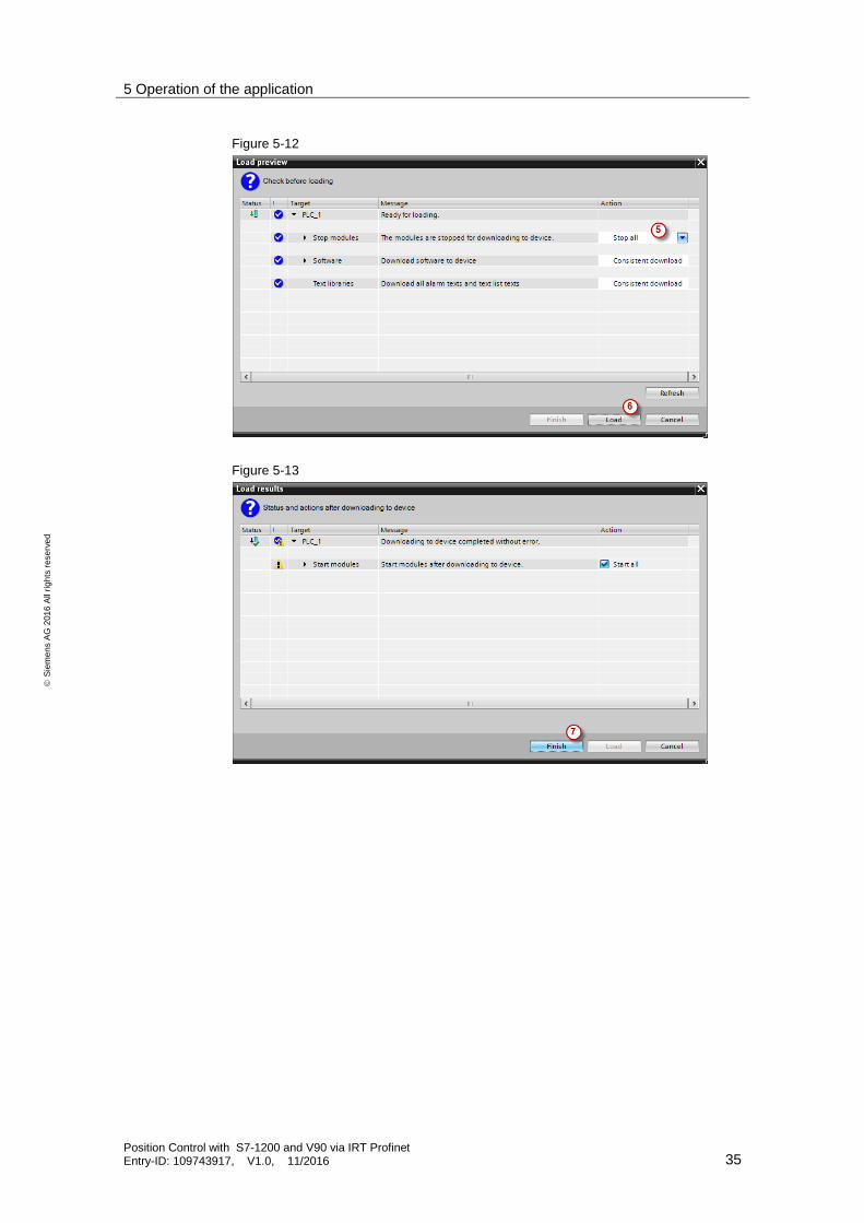
10. Compile the project and then download it into device.
Figure 5-10
Figure 5-11
5 Operation of the application
Position Control with S7-1200 and V90 via IRT Profinet Entry-ID: 109743917, V1.0, 11/2016 35
S
iem
en
s A
G 2
01
6 A
ll ri
gh
ts r
ese
rve
d
Figure 5-12
Figure 5-13

5 Operation of the application
Position Control with S7-1200 and V90 via IRT Profinet Entry-ID: 109743917, V1.0, 11/2016 36
S
iem
en
s A
G 2
01
6 A
ll ri
gh
ts r
ese
rve
d
11. Switch to the commissioning panel by double-clicking the “Commissioning” under the technology object tree:
Figure 5-14
12. Click the “Activate” button:
Figure 5-15
13. In the pop-up dialog box, click “OK” button to proceed the operation.
Figure 5-16
5 Operation of the application
Position Control with S7-1200 and V90 via IRT Profinet Entry-ID: 109743917, V1.0, 11/2016 37
S
iem
en
s A
G 2
01
6 A
ll ri
gh
ts r
ese
rve
d
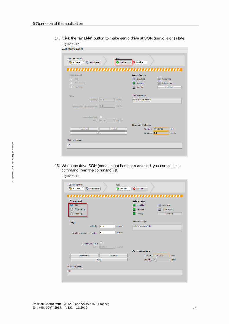
14. Click the “Enable” button to make servo drive at SON (servo is on) state:
Figure 5-17
15. When the drive SON (servo is on) has been enabled, you can select a command from the command list:
Figure 5-18

5 Operation of the application
Position Control with S7-1200 and V90 via IRT Profinet Entry-ID: 109743917, V1.0, 11/2016 38
S
iem
en
s A
G 2
01
6 A
ll ri
gh
ts r
ese
rve
d
16. Select the command “Homing”, and then click “Set home position” to set current position to be position 0:
Figure 5-19
17. Press the command of “Positioning” :
Figure 5-20
18. Input values for positioning, for example, travel by a position or to target position of 100 mm with acceleration/deceleration of 50 mm/s^2:
Figure 5-21
Remarks:
According to the configuration of mechanics, 100 mm means 10 motor revolutions.

5 Operation of the application
Position Control with S7-1200 and V90 via IRT Profinet Entry-ID: 109743917, V1.0, 11/2016 39
S
iem
en
s A
G 2
01
6 A
ll ri
gh
ts r
ese
rve
d
19. Press “Absolute” or “Relative” to move the axis:
Figure 5-22
20. Deactivate the axis control and switch to offline mode. Open the main program block OB1 after that.
21. Program with the technology instructions at the right side:
Figure 5-23

5 Operation of the application
Position Control with S7-1200 and V90 via IRT Profinet Entry-ID: 109743917, V1.0, 11/2016 40
S
iem
en
s A
G 2
01
6 A
ll ri
gh
ts r
ese
rve
d
22. Program as follows:
5 Operation of the application
Position Control with S7-1200 and V90 via IRT Profinet Entry-ID: 109743917, V1.0, 11/2016 41
S
iem
en
s A
G 2
01
6 A
ll ri
gh
ts r
ese
rve
d
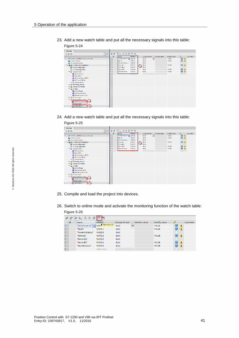
23. Add a new watch table and put all the necessary signals into this table:
Figure 5-24
24. Add a new watch table and put all the necessary signals into this table:
Figure 5-25
25. Compile and load the project into devices.
26. Switch to online mode and activate the monitoring function of the watch table:
Figure 5-26

5 Operation of the application
Position Control with S7-1200 and V90 via IRT Profinet Entry-ID: 109743917, V1.0, 11/2016 42
S
iem
en
s A
G 2
01
6 A
ll ri
gh
ts r
ese
rve
d
27. Modify M10.0 to 1 to make drive SON:
Figure 5-27
28. Modify M10.2 to 1 to perform homing:
Figure 5-28
29. Modify M10.2 to 0 to complete homing and then modify M10.4 to 1 to move absolute position of 1000 mm with the speed of 100 mm/s:
Figure 5-29
30. Modify M10.4 to 0 and then modify M10.5 to 1 to move a position of 100 mm with the speed of 100 mm/s:
Figure 5-30
31. Modify both M10.4 and M10.0 to 0 to complete operation.
6 Related literature
Position Control with S7-1200 and V90 via IRT Profinet Entry-ID: 109743917, V1.0, 11/2016 43
S
iem
en
s A
G 2
01
6 A
ll ri
gh
ts r
ese
rve
d
6 Related literature
Table 6-1
Topic
\1\ Siemens Industry Online Support
http://support.industry.siemens.com
\2\ Download page of this entry
https://support.industry.siemens.com/cs/ww/en/view/109743917
\3\
7 Contact
Siemens Ltd., China
DF M3-BF GMC
No. 18 Siemens Road Jiangning Development Zone
Nanjing, 211100 China mailto: [email protected]
8 History
Table 8-1
Version Date Modifications
V1.0 11/2016 First version
Related Documents