CIROS Studio is the software for 3D factory simulation. With CIROS Studio, users model layouts and processes, simulate robotic work cells and automated manufacturing plants, and visualize complex sequences. CIROS Studio brings together the domains planning, design, electrical wiring, controller development, commissioning, sales, and marketing. For more than twenty years now, we have been developing the software, distributing our solutions successfully in industry, and offering maintenance, support, training, and services. If you want to learn more about CIROS Studio addressing your individual use case we will be glad to fix a date for a web-based presentation. In the following, you will find an overview of CIROS Studio. Application Areas Among others, CIROS Studio is used for the following applications: • Implementation of the Digital Twin for Industry 4.0 • Layout planning for new and existing factories, plants, and stations • Machine concatenation / plant chains • Cycle time planning and optimization • Automatic computation of treatment trajectories on work piece surfaces and along outlines plus optional manual post-processing • Offline programming of robots in manufacturer’s language • Reachability and collision analyses for robots and other kinematics • Validation of controller programs for PLCs • Virtual commissioning with real PLCs and real field busses • Interactive virtual reality presentations of plants and processes in real time • Creation of videos for presentation and training

Welcome message from author
This document is posted to help you gain knowledge. Please leave a comment to let me know what you think about it! Share it to your friends and learn new things together.
Transcript

CIROS Studio is the software for 3D factory simulation. With CIROS Studio, users model layouts and
processes, simulate robotic work cells and automated manufacturing plants, and visualize complex
sequences. CIROS Studio brings together the domains planning, design, electrical wiring, controller
development, commissioning, sales, and marketing.
For more than twenty years now, we have been developing the software, distributing our solutions
successfully in industry, and offering maintenance, support, training, and services. If you want to
learn more about CIROS Studio addressing your individual use case we will be glad to fix a date for a
web-based presentation. In the following, you will find an overview of CIROS Studio.
Application Areas Among others, CIROS Studio is used for the following applications:
• Implementation of the Digital Twin for Industry 4.0
• Layout planning for new and existing factories, plants, and stations
• Machine concatenation / plant chains
• Cycle time planning and optimization
• Automatic computation of treatment trajectories on work piece surfaces and along outlines plus
optional manual post-processing
• Offline programming of robots in manufacturer’s language
• Reachability and collision analyses for robots and other kinematics
• Validation of controller programs for PLCs
• Virtual commissioning with real PLCs and real field busses
• Interactive virtual reality presentations of plants and processes in real time
• Creation of videos for presentation and training

Industrial Sectors CIROS Studio users mainly come from the following industrial sectors:
• Automotive supply
• Automation engineering
• Machine building, mechanical engineering
• Plant engineering
• Metal processing, machine tools
• Engineering offices
• Simulation service providers
• Research institutes
Highlights These are the top features of CIROS Studio:
• Kinematic 3D simulation even of comprehensive manufacturing plants in real time
• Robots of different manufacturers together in one model
• Large model libraries, e.g. more than 1,000 robots from 15 manufacturers
• Easy modeling of user-defined kinematics
• Simulation of mechanics, sensors, and transport
• Simulation of physical effects and coating processes
• Support of robot languages KRL (KUKA), RAPID (ABB) und MELFA BASIC (Mitsubishi)
• Script language IRL for sequence control and for robots by all manufacturers
• Coupling of original controller equipment, e.g. Siemens, Beckhoff, and 3S
• CAD import with 19 tools for semi-automatic geometry optimization and model reduction
• Robot-independent planning of processes based on movement paths
• Free camera cruises and creation of videos
• Animation of simple processes as an alternative to true simulation
• Complete online help with introductory examples
• Precisely structured work flows to achieve results in short time
Software Packages CIROS Studio is the modular software for 3D factory simulation. By assembling relevant packages,
you will obtain the optimal software for exactly your use case. Additional packages can be added fast
and easily at a later date. The following packages are available:
Basic Package The basic package allows for the modeling and simulation of geometries, mechanics, and electrics.
Geometrical Model

• Clearly structured hierarchy of model elements
• Geometries are represented by surfaces consisting of polyhedrons (facets) and polyhedron
points (vertices)
• Coordinate systems describe positions and orientations of all elements
• Simple CAD functions: creation of rotational and translational bodies from user-defined flat
geometries
• Level of detail: support of switchable levels of detail for geometries
• Render clones for high-performance visualization of geometrically identical objects
• Dimensioning of layouts, assemblies, and gaps – visualized without overlapping
Mechanical Model
• Fully functional kinematics even without geometry
• Complex kinematics are modeled as sequences of translational and rotational axes
• User-defined kinematics with Denavit-Hartenberg parameters
• Gripping procedures for the movement of work pieces and components
• Control of mechanical assemblies and kinematic chains by electrical inputs, taught positions, or
user-defined controller programs
Electrical Model
• Digital and analog I/Os for reality compliant modeling of electrics
• I/O panel for management of electrical connections and circuit diagram planning
o Hierarchical display of I/Os ordered by plant components
o Free selection of displayed I/Os for clearly arranged diagrams
o Graphical connecting of I/Os
o Display and manual setting of I/O signal values
• Assignment and management of resource labels and item designations

Modeling Functions
• Movement paths (linear, PTP, circular, spline) and path nodes for robot movements and
animations
• Nested object functions for calculations during simulation: arithmetic, trigonometry, Boolean
algebra, high-level language control structures, access to static and dynamic properties of the
model (geometry, mechanics, and electrics), random numbers, etc.
• Connectors and triggers for the automatic geometrical snapping and the functional connection of
I/Os and gripping relations during modeling and simulation time
• Deformation-free scaling of assemblies for user-defined model library components, also suitable
for mechanically functional elements
• Hierarchical referencing of ready-made subordinate models
• Model libraries: geometric primitives, textures and materials, I/O controllers, interactive
elements
Simulation
• Kinematic 3D simulation with automatic real time control
• Time-discrete simulation: user-defined simulation cycles down to 1 ms
• Deterministic reproduction of simulation runs
• Object sources and sinks to create and delete elements during simulation
• Arbitrary number of simultaneously simulated controllers, e.g. robots, I/O controllers, or PLCs –
restricted only by the performance of the employed computer
• Line-by-line sequence tracing for running programs during simulation
• Drawing and export of characteristic curves, e.g. positions, speeds, accelerations, I/O values, and
multiple performance data
Visualization
• High-performance renderer for realistic model visualization
• Shading and SSAO (screen space ambient occlusion)
• Arbitrary number of independent viewing windows simultaneously
• User-defined sectional views

• Stereoscopic visualization in many formats, compatible with most 3D TVs and 3D projectors
• Visualization of point clouds from laser scans
• Multiple light sources with parameters: ambient light, directional lights, point lights, head light
• Materials with optical and other physical properties
• Textures from graphics files
Interaction and Media
• User interaction at any time during simulation
• Clickable 3D elements in the model (e.g. a switch within a plant)
• Clickable 2D elements in the viewing window (e.g. a tile to trigger an action)
• Coupling of 3D mice and gamepads for navigation and interaction
• Playback of videos, 3D videos, and webcam streams in the model
• Presentation control: changing between predefined views by electrical inputs
• Action objects for interaction and media content, e.g. sounds, websites, and messages
• Optional water mark in the viewing window
Operation
• Model Explorer for hierarchically structured access to all model elements
• Management of all properties of all model elements
• Management of provided and user-defined model libraries
• Structured access to all application options and model options
• Version management for the backup of intermediate versions
• Graphical edit mode for geometrical modeling directly in the 3D view
• 3D marker: extra coordinate system for multiple alignment operations
• Model analysis to reveal possible modeling errors
• General find and replace function
• Structured management of controller projects, programs, and position lists
• Object labelling and selection in the 3D view
• Pixel-accurate sizeable screenshots of the current view in high resolution, also for high-quality
printing

• F1-evoked context sensitive online help system with introductory examples
• Many operation options known from Windows: configurable toolbars, context menus, keyboard
shortcuts, dock windows, undo function, copy & paste, drag & drop, etc.
• User interface for high-resolution displays with 100%, 125%, 150%, or 200% scaling level
• Information on software updates
Model Import Package
• Import of 3D CAD data in formats STEP (AP 203 and AP 214), IGES, VRML, STL, 3ds Max, AutoCAD
DXF, Autodesk FBX, Blender, Collada, and Wavefront Object
• Export plugins for Autodesk Inventor and Autodesk 3ds Max
• 19 tools for semi-automatic geometry optimization and model reduction of large CAD data
o Find problems
o Close gaps in surface
o Replace selection by enveloping body
o Select identical elements
o Close drill holes
o Delete inside of primitive body
o Delete contained geometries
o Reduce polygons
o Simplify rounded edges
o Merge vertices
o Clean up geometry
o Copy structure into elements
o Optimize for rendering
o Fit coordinate systems to hulls
o Change cylinder approximation
o Merge hulls with matching material or color
o Create render clones for similar objects
o Edit facets
o Simplify object hierarchy
• Automatic path generation on surfaces, along sharp edges, at geometric features, or by pattern
projection (meander, helix)
• Vertex normal generation for fluent color gradients at polyhedron edges
Model Import in Proprietary Formats • For the import of 3D CAD data in the following manufacturer formats, independent software
packages are available: JT, NX, CATIA (V4, V5, or V6), Creo, Inventor, SolidWorks, Solid Edge,
Parasolid, ACIS, and Industry Foundation Classes (IFC).

Model Export Package • Export of 3D geometry data in formats STEP, IGES, VRML, STL, and DXF (AutoCAD R12) and for
the POV-Ray ray tracer
Mechanisms Package With the mechanisms package, you add motion to your models and simulate mechanics, sensors, and
transport.
Extended Mechanisms Simulation
• Translational (thrust axes) and rotational (turn axes) degrees of freedom, e.g. for pneumatic
cylinders and kinematic chains
• Configurable drives, also with user-defined motion profiles
• Gripping mechanisms
• Gears and gear wheels
• Model library with ready-made mechanisms
Sensor Simulation
• Representation of real sensors in the plant model
• Many sensor types: inductive and capacitive proximity switches, optical distance sensors, light
barriers, ultrasonic sensors, safety laser scanners, cameras for position and orientation
detection, barcode readers, and transceiver-transponder systems (RFID systems)
• Optional 3D visualization of measuring ranges and detected elements
• Parameters for measuring range, apex angle, input and output characteristics, and other
properties
• Model library with typical sensors

Transport Simulation
• Modeling and simulation of discrete track-bound transport systems, e.g. work piece carrier
transfer systems, autonomous guided transport systems, or part magazines
• Suitable for simple components or complete logistics systems
• Text-based low-level modeling for the creation of functionally detailed components, also for
model libraries
• Graphical high-level modeling for the composition of complex comprehensive plants by snapping
together pre-modeled components from model libraries in 3D space
• Realistic contact behavior based on geometric shells
• Physical simulation of sliding friction and gravity
• Model library with invisible functional elements for the enhancement of non-functional CAD data
• Model libraries for the transport systems Bosch TS2plus and ASYS TECTON
More Features
• Hose, wire, and drag chain simulation for predefined models
• Geometrical gripping, e.g. for exact gripping procedures with parallel grippers
• Model libraries: LEDs and displays, modeling essentials, grippers
Robotics Package The robotics package is the basis for the modeling and the simulation of robots.
General Features
• Virtual robot controller
• Robots of different manufacturers together in one model
• Virtual teach-in to move a robot in a model
• Management of robot TCPs (tool center points)
• Visualization of robot work spaces, also for user-defined TCPs
• Reachability analyses based on kinematic data provided by the robot manufacturer
• Linear and rotatory additional axes
• Integrated programming environment
o Syntax highlighting within the source code

o Error inspection by compiling source code for a virtual controller
o Incorrect lines can be jumped at directly
• Model libraries: robots standard kinematics for test purposes, additional axes
Coordinate Transformation
• Robot pose and robot movement in joint coordinates and cartesian coordinates
• Analytic inverse kinematics for many kinematics types: 4-, 5-, and 6-axis kinematics, delta
kinematics with rotational or linear axes
• Parameterizable universal coordinate transformation for further kinematics, e.g. KUKA LBR iiwa
Positions
• Positions are stored with pose (x, y, z, roll, pitch, and yaw), configuration, and turns.
• Positions can be directly transferred between the 3D view and position lists
• Teaching of positions
o By using the teach-in in an arbitrary coordinate system
o By clicking into the 3D view
o By clicking a stored position or a path node
o Relatively to existing elements
o By entering coordinates directly
• If a position defined by a path node is approached repeatedly, the position will be approached in
all possible robot configurations sequentially
Programming
• Robot programming language IRL according to DIN 66312. IRL is a simple high-level programming
language for the programming of robots by arbitrary manufacturers.
• Programming assistant for the automatic creation of robot programs in manufacturer’s language
Collision Detection
• For arbitrary elements of the model, in particular for robots, grippers, and gripped components,
but also for work piece carriers
• Configurable response to collision events

o Visualization of colliding components
o Logging of colliding components with time stamp for later analysis of unattended
simulation runs
o Simulation stop for detailed analysis
• Performance enhancement by explicit configuration of critical components for testing
• Consideration of safety distances by automatic extrusion of components
Robot Package ABB with RAPID • Model library ABB robots
• Robot programming language RAPID (ABB): support of the most important language elements
• Direct exchange of robot positions (robtarget), work piece coordinate systems (wobjdata), and
tools (tooldata) between 3D view and RAPID program
Robot Package KUKA with KRL • Model library KUKA robots
• Robot programming language KRL (KUKA): support of the most important language elements
Robot Package Mitsubishi with MELFA-BASIC • Model library Mitsubishi robots
• Robot programming languages MELFA-BASIC III, IV, and V (Mitsubishi): support of about 95 % of
the language elements
• Model assistant for robot cells
Mitsubishi Online Coupling • Connection to the real Mitsubishi controller via Ethernet, RS232, or USB (controller-dependent)
• Upload and download of programs and machine data
• Together with additional features, Mitsubishi online coupling is also available as the stand-alone
software CIROS Programming.
Robot Package Adept with V+ • Robot programming language V+ (Adept, Version 12)
• Model library Adept robots
Robot Package Stäubli / CS8 Emulator • Model library Stäubli robots
• Coupling of the Stäubli CS8 Emulator with VAL3 for joint values
Robot Package FANUC • Model library FANUC robots
Robot Package Miscellaneous Robots • Model library robots: Comau, Denso, Epson, Kawasaki, Yaskawa Motoman, Nachi, Reis, Universal
Robots
Controller Package • Virtual Commissioning – Hardware in the Loop (HIL) – Emulation: development and test of
controller software running on real controller hardware against the virtual plant
• OPC client
o OPC DA (Data Access)
o OPC UA (Unified Architecture)

o High-performance OPC clients, suitable for most control scenarios
o Convenient configuration with items provided by OPC servers
o Automatic model-internal configuration: I/Os of the components of the virtual field level
are connected to newly created I/Os of the controller according to their names
• OPC server
o OPC DA (Data Access)
o OPC UA (Unified Architecture)
o Coupling of external operating units or external PPS/MES/PDA software
• Coupling Beckhoff TwinCAT
o For the coupling of real controller hardware via real field bus hardware
o Direct access to EtherCAT
o Access to other field bus systems via bus terminals provided by Beckhoff e.g. for RS232,
RS485, AS-Interface, PROFINET-RT, PROFINET-IRT, EtherNet/IP, IEEE-1588, Lightbus,
PROFIBUS-DP, Interbus, CANopen, DeviceNet, DMX
• Coupling Siemens PLCSIM
o Coupling of the software Siemens SIMATIC PLCSIM from version 5.4 SP3 for the
simulation of programs for S7-300 and S7-400
• Coupling Siemens PLCSIM Advanced
o For example, for Siemens S7-1500
• Coupling Delta Logic ACCON-AGLink
o For example, to access Siemens S7-1200 and S7-1500
• Coupling MathWorks MATLAB
o Communication between CIROS elements and MATLAB scripts
• Coupling MathWorks Simulink
o Communication between CIROS elements and Simulink models
• Emulation Siemens STEP 7
o Simple STEP 7 projects (*.s7p) can be loaded directly and are emulated to control models
• Model library PLC: OPC, Siemens, TwinCAT
Camera Cruise and Video Recording • Camera cruises with arbitrary numbers of camera positions and scenes, also sectional views
• Automatic and fluent transition between scenes
• User-defined durations for scenes and transitions
• Three camera modes: static positions, fixed to a moving object, or chase camera
• Camera cruise during simulation in real time
• Video recording with codecs installed in the system
• Post-processing with video editing software possible
Virtual Human • Model library virtual human (virtual worker) with 30 degrees of freedom
• Body postures are taught according to robot teaching
• Position lists store body postures
• Simulation interpolates between two body postures
• [This package requires the robotic package.]
Model Animation Package The model animation package contains features for plausible visualizations while avoiding complex
modeling for true simulation.

Animation Designer
• Simple animation of objects
• Movement paths for the definition of motion trajectories in 3D space
• Arrangement of movement paths over the time scale
• Combined use with simulated mechanisms and kinematics
Physical Effects
• Physical effects bases on NVIDIA PhysX
• Consideration of gravity, friction, and impact
• Parameters for static friction, sliding friction, restitution coefficients, and density/weight
• Conveyor belts, controlled by electrical inputs: speed, acceleration, running direction, activation
• Combined use with simulated mechanisms and kinematics
Process Simulation for Coating Processes
• Process tools with parameters
• Process work pieces’ geometry is triangulated automatically
• Visualization of the coating intensity by true colors or pseudo colors
Model Manipulation • Programming language Python for modeling and simulation control
Planner (Plug-in) The Planner is used for analyzing cycle times during the life cycle of a plant.
Cycle Time Planning / Mechanical Design
• Gantt diagrams to describe the sequence of all actions
• Easy modeling of durations and dependencies of actions
• Parallel sub-processes
• Different types of dependencies: simple, AND, OR
• Instant automatic calculation of the critical path and the total cycle time
• Sub-diagrams for the structuring of large processes

• Actions can be marked as dependent on sensors or initiators of the 3D plant model
• Considerably more convenient than by-hand methods or spreadsheets
Sequential Flow Charts
• Sequential Function Charts (SFC) according to IEC 61131-3
• Sequences with steps, transitions, actions, conditions, and jumps
• Fully automatic creation of SFCs from cycle time diagrams with sensor-dependent actions
• Export of SFCs according to IEC into a real PLC
Model Control
• Control of the 3D plant model according to actions of cycle time diagrams or according to SFCs
• Visualization of the whole process implemented in the plant model
Circuit Diagram Planning / Electrical Design
• Management of I/O modules and valve clusters
• Graphical assignment of actuators and sensors
• Export for the EPLAN circuit diagram generator (“Schaltplangenerator”)

Cycle Time Analysis
• Logging of cycle time diagrams from running simulations
• Comparison of cycle time diagrams
More Features
• Documentation compilation
• Some functions of this package are also available as the stand-alone software CIROS Planner.
VR Package • Multi-screen projection: visualization of the whole model over multiple screens, also
stereoscopic
• Coupling of the VR glasses Oculus Rift and HTC Vive
• Coupling of interaction devices
Viewer Package • Model export into a HTML5 file for navigable viewing in a browser.
• This feature can be used similar to 3D PDF to communicate models.
CIROS Player • Stand-alone software for the interactive simulation of models created with CIROS Studio.
Outlook We continuously advance CIROS Studio. The following features are planned for one of the next
releases:
• Interactive simulation films and video recording (completely new camera cruise) [Camera Cruise
and Video Recording]
• Streaming of simulation runs for viewing in a browser [Viewer Package]
• Import of 2D layouts in DWG format [Model Import in Proprietary Formats]
• Optimized TCP visualization [Robotics Package]
• Convenient display and selection of the current TCP of a robot in the toolbar [Basic Package]
• I/O monitors for user-defined display of I/Os [Basic Package]
• Extended undo functionality, especially for I/O operations [Basic Package]
• Extended find and replace [Basic Package]
• Graphical 3D Marker alignment at the bounding box of the selection [Basic Package]
• Complete revision of the inspection mode for clear views [Basic Package]
• New object replacer for combined use of the functions of object source and object sink [Basic
Package]
• Easy connection of a multi selection of I/Os by drag & drop [Basic Package]
What CIROS Studio is not … CIROS Studio can do a lot – but not everything:
• CIROS Studio is not a CAD (computer-aided design) software. You may consider NX, CATIA,
Inventor, Creo, SolidWorks, Solid Edge, or others instead.
• CIROS Studio is not a DES (discrete event simulation) software. For example, you cannot simulate
the annual throughput of a logistics warehouse in a few seconds. You may consider Plant
Simulation, AnyLogic, or others instead.
• CIROS Studio is not an MBS (multibody simulation) software. The are no masses, forces, or
torques. You may consider Adams or others instead.
• CIROS Studio is not an FEM (finite element method) software. There is no deformation. You may
use ANSYS or others instead.
• CIROS Studio is not a simulation for electrical networks. There are no voltages or currents. You
may consider LTSpice or others instead.
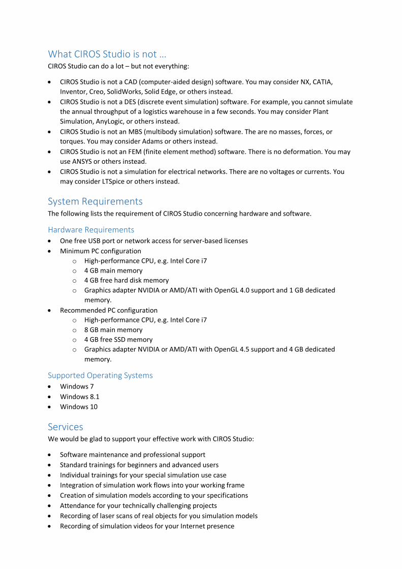
System Requirements The following lists the requirement of CIROS Studio concerning hardware and software.
Hardware Requirements • One free USB port or network access for server-based licenses
• Minimum PC configuration
o High-performance CPU, e.g. Intel Core i7
o 4 GB main memory
o 4 GB free hard disk memory
o Graphics adapter NVIDIA or AMD/ATI with OpenGL 4.0 support and 1 GB dedicated
memory.
• Recommended PC configuration
o High-performance CPU, e.g. Intel Core i7
o 8 GB main memory
o 4 GB free SSD memory
o Graphics adapter NVIDIA or AMD/ATI with OpenGL 4.5 support and 4 GB dedicated
memory.
Supported Operating Systems • Windows 7
• Windows 8.1
• Windows 10
Services We would be glad to support your effective work with CIROS Studio:
• Software maintenance and professional support
• Standard trainings for beginners and advanced users
• Individual trainings for your special simulation use case
• Integration of simulation work flows into your working frame
• Creation of simulation models according to your specifications
• Attendance for your technically challenging projects
• Recording of laser scans of real objects for you simulation models
• Recording of simulation videos for your Internet presence

• Implementation, delivery, and commissioning of your complete virtual reality site
• Consulting for all your questions dealing with simulation and virtual reality
Distributors and Prices Are you are interested in using CIROS Studio? This is how to go on:
• Do you intend to use CIROS Studio commercially? In this case, please contact us directly. We
support you in choosing appropriate modules and submit you an individual offer.
• For the use of CIROS Studio in education, further education, and non-commercial research,
please contact our partner Festo Didactic. You can find information on available versions and
prices here: http://www.festo-didactic.com/int-en/learning-systems/software-e-learning/ciros
Links Here, you can find further information on CIROS Studio on the Internet:
• Videos of simulations in the YouTube channel of CIROS:
https://www.youtube.com/user/CirosEng
• Up-to-date articles around CIROS in our Google+ channel:
https://plus.google.com/115876165980875991963
Downloads Here, you can download further information on CIROS Studio:
• The product information as a PDF – suitable for printing
• All pictures in HD quality as a ZIP

CIROS Studio Product Information
July 2018
http://www.verosim-solutions.com/en/ciros-studio
VEROSIM Solutions
RIF Institut für Forschung und Transfer e.V.
Joseph-von-Fraunhofer-Str. 20
44227 Dortmund
Germany
Phone: +49 231 586984-80
Fax: +49 231 586984-89
E-mail: [email protected]
Internet: http://www.verosim-solutions.com/en/
Related Documents