Appendix P Draft Bridge Design Hydraulic Study For the State Route 32 Widening Between Fir Street and Yosemite Drive at Dead Horse Slough and South Fork Dead Horse Slough in the City of Chico, California

Welcome message from author
This document is posted to help you gain knowledge. Please leave a comment to let me know what you think about it! Share it to your friends and learn new things together.
Transcript

Appendix P Draft Bridge Design Hydraulic Study For the
State Route 32 Widening Between Fir Street and Yosemite Drive at Dead Horse Slough and
South Fork Dead Horse Slough in the City of Chico, California


Draft
Bridge Design Hydraulic Study
For the State Route 32 Widening Between Fir Street and Yosemite Drive
At Dead Horse Slough and South Fork Dead Horse Slough in the City of Chico, California
Prepared By
August 2006
Prepared for
City of Chico Department of Public Works
Mark Thomas and Company, Inc


SR 32 Widening at Dead Horse Slough and South Fork Dead Horse Slough
City of Chico
Draft
Bridge Design Hydraulic Study
For the State Route 32 Widening
Between Fir Street and Yosemite Drive Over Dead Horse Slough and South Fork Dead Horse Slough
in the City of Chico, California
Submitted to
City of Chico
Department of Public Works &
Mark Thomas and Company, Inc
This report has been prepared by or under the supervision of the following Registered Engineer. The Registered Civil Engineer attests to the technical information contained herein and has judged the qualifications of any technical specialists providing engineering data upon which recommendations, conclusions, and decisions are based.
_________________________________ Han-Bin Liang, Ph.D., P.E. Registered Civil Engineer
April 2006


SR 32 Widening at Dead Horse Slough and South Fork Dead Horse Slough
City of Chico
Draft Bridge Design Hydraulic Study ii August 2006
TABLE OF CONTENTS Page No.
EXECUTIVE SUMMARY............................................................................iii I. INTRODUCTION........................................................................................1 II. DESCRIPTION OF WATERSHED.............................................................5 III. DESCRIPTION OF STREAM AND SITE ...................................................7 IV. HYDROLOGY ............................................................................................9 V. HYDRAULIC ANALYSIS..........................................................................12 VI. SCOUR ANALYSIS..................................................................................16 VI. REFERENCES.........................................................................................18
LIST OF TABLES Table 1 Hydraulic Summary – Dead Horse Slough at SR 32.............................................iii Table 2 Hydraulic Summary – South Fork Dead Horse Slough at SR 32 ..........................iv Table 3 Potential Scour Depths for SR 32 Bridge Widening over Dead Horse Slough......iv Table 4 Dead Horse Slough Design Flows ........................................................................ 9 Table 5 South Fork Dead Horse Slough Design Flows.................................................... 11 Table 6 Dead Horse Slough Water Surface Elevations at River Station 10762 (Just upstream of proposed bridge) .................................................................... 12 Table 7 South Fork Dead Horse Slough Water Surface Elevations at River Station 1485.7 (Just upstream of RCB)........................................................................... 13 Table 8 Flow Velocities in Main Channel at River Station 10762 (Just upstream of proposed bridge) ................................................................................................. 13 Table 9 Flow Velocities in Main Channel at Upstream and Downstream Ends of Culvert ................................................................................................................. 14 Table 10 Summary of Scour............................................................................................... 17 LIST OF PHOTOS Photo 1 SR 32 Bridge Over Dead Horse Slough (Looking East)........................................ 1 Photo 2 SR 32 RCB at South Fork Dead Horse Slough (Upstream Face)......................... 2 Photo 3 Downstream End of South Fork Dead Horse Slough Along SR 32, Looking West .......... 5 Photo 4 SR 32 Bridge looking downstream........................................................................ 7 Photo 5 SR 32 RCB looking upstream ............................................................................... 7 Photo 6 California Park Lake Outlet ................................................................................. 10 Photo 7 Downstream Headwall of South Fork RCB ......................................................... 10 LIST OF FIGURES Figure 1 Project Location Map............................................................................................. 3 Figure 2 Project Vicinity Map............................................................................................... 4 Figure 3 Watershed Boundary............................................................................................. 6 Figure 4 Dead Horse Slough Extrapolated Flows ............................................................... 7 Figure 5 Design Hydrographs at South Fork Dead Horse Slough..................................... 11 Figure 6 Profiled of Dead Horse Slough at SR 32............................................................. 15 APPENDICES Appendix A HEC-RAS Run - Existing Conditions Appendix B HEC-RAS Run - Proposed Conditions Appendix C Proposed Bridge Plans Appendix D Hydrologic Analyses Appendix E Scour Analysis Calculations

SR 32 Widening at Dead Horse Slough and South Fork Dead Horse Slough
City of Chico
Draft Bridge Design Hydraulic Study iii August 2006
EXECUTIVE SUMMARY This study presents the hydrologic and hydraulic assessment of Dead Horse Slough and South Fork Dead Horse Slough crossings of State Route 32 (SR 32) in the existing and proposed conditions. The city of Chico is proposing to widen SR 32 from 2 lanes to 4 lanes between Fir Street to just east of Yosemite Drive in the city of Chico, California.
The widening project is necessary to accommodate major development projects planned for the area. The project is in the city’s General Plan and is planned to go to construction in 2008. The proposed improvements include widening the stream crossings which will affect the hydraulics of the Dead Horse Slough and South Fork Dead Horse Slough.
The South Fork Dead Horse Slough flows north-north-west under SR 32 through a box culvert just east of Bruce Road (and just downstream of California Park Lake). Just north of SR 32, South Fork Dead Horse Slough joins the main Dead Horse Slough then flows west under Bruce Road and roughly parallels SR 32 on the north side for 450 feet (ft) until the slough turns south and passes under SR 32 beneath the Dead Horse Slough Bridge (CT Bridge No. 12C-0138). Dead Horse Slough flows into Little Chico Creek 740 ft downstream of the SR 32 crossing.
The proposed improvement to the main Dead Horse Slough crossing is to widen the existing bridge by approximately 49 feet to the north to make the total bridge width 81.5 ft. The widening will include extension of the 3 pile bents and 2 abutments. The existing bridge will not be lengthened.
The proposed improvement to the South Fork Dead Horse Slough crossing is to extend the existing 8’x6’ box culvert. This will be done by extending the culvert 14 feet to the south, and 39.5 feet to the North with new headwalls.
The water surface elevations and flow velocities in Table 1 are located at the modeled cross-section just upstream of the proposed SR 32 Bridge over Dead Horse Slough. The downstream controlling water surface elevation is based on the FEMA 100-year flood elevation. This information was obtained from the current FEMA Flood Insurance Study (FIS) for Butte Count and Incorporated Areas (2000), and the 2005 FEMA issued Letter of Map Revision (LOMR) for the area. The proposed bridge design has 2.21 ft above the Q200 flood. This does not meet the city of Chico’s stringent freeboard design criteria of 3 ft above the 200-year flood, but does meet Federal Highway Administration’s (FHWA) and Caltrans design criteria for bridges on State highways. The Caltrans’ criteria are 100-year without freeboard and 50-year plus 2 ft of freeboard for bridges.
Table 1 - Hydraulic Summary – Dead Horse Slough at SR 32 Design Flow
Return Period Design Flow
(ft3/s) Bridge Soffit
Elevation (est.) (ft) Water Surface Elevation (ft)
Freeboard (ft)
Velocity (ft/s)
200-year 2,200 ~240.7 238.49 2.21 5.72 100-year 1,900 ~240.7 237.96 2.74 5.45 50-year 1,500 ~240.7 237.24 3.46 5.07
The water surface elevations in Table 2 are at the modeled cross-section just upstream of the proposed RCB culvert under SR 32 along South Fork Dead Horse Slough. The culvert design meets Caltrans’ design criteria of the culvert not causing objectionable backwater during 100-year event”, and the 100-year water surface will not spread into the travel way.

SR 32 Widening at Dead Horse Slough and South Fork Dead Horse Slough
City of Chico
Draft Bridge Design Hydraulic Study iv August 2006
Table 2 - Hydraulic Summary – South Fork Dead Horse Slough at SR 32
Return Period
Design Flow (ft3/s)
Edge of Travel Way
Elev. (ft)
RCB Top Elev.
(est.) (ft)
Water Surface
Elevation (ft)
Upstream Velocity**
(ft/s)
Downstream Velocity***
(ft/s) 100-year 470 ~255.8 252.3 254.55 0.54 18.97 50-year 430 ~255.8 252.3 254.13 0.57 18.65 25-year 360 ~255.8 252.3 253.26 0.64 17.93 10-year 290 ~255.8 252.3 252.31 0.70 17.07
*the 10-year water surface as indicated is at the cross-section upstream of the culvert opening. The 10-year water surface elevation at the culvert opening is 249.73 feet as indicated in Appendix B. **the Upstream Velocities as indicated are at the cross-section upstream of the culvert opening ***the Downstream Velocities as indicated are at the downstream culvert opening (not the downstream cross-section) The scour analysis performed in this study follows the FHWA recommended methodology. Table 3 summarizes the estimated potential total scour depth at the abutments and pile bents for the SR 32 Bridge over Dead Horse Slough.
Table 3. Potential Scour Depths for SR 32 Bridge Widening over Dead Horse Slough (below grade)
Location Long-Term Bed Change
Contraction Scour
Local Scour Total Scour Depth
Abutment 1 Negligible 0.32 ft 3.31 ft 3.63 ft Bent 2 Negligible 0.32 ft 7.02 ft 7.34 ft Bent 3 Negligible 0.32 ft 6.68 ft 7.00 ft Bent 4 Negligible 0.32 ft 5.35 ft 5.67 ft
Abutment 5 Negligible 0.00 ft 0.00 ft 0.00 ft
The foundation of the proposed bridge abutments and pile bents should be constructed below the calculated total potential scour to avoid structural damage and/or undermining. Protection measures such as rock slope protection (RSP), are also recommended for the abutments of the proposed bridge widening.
For the South Fork Dead Horse Slough culvert extension, we recommend the installation of Rock Slope Protection ¼ ton (RSP) at the downstream end of the culvert extension. This RSP will help dissipate the high flow velocities (as indicated in Table 2) at the outfall the culvert, and protect the channel from scour.


SR 32 Widening at Dead Horse Slough and South Fork Dead Horse Slough
City of Chico
Draft Bridge Design Hydraulic Study 1 August 2006
I. INTRODUCTION Background:
The purpose of this study is to provide hydrologic and hydraulic data for the design of State Route 32 (SR 32) at Dead Horse Slough and South Fork Dead Horse Slough. The city of Chico proposes to widen SR 32 from east of Fir Street to Yosemite Drive. The project extends through the Bruce Road/SR 32 intersection. The widening will occur to the north between Fir Street and Bruce Road, where available right-of-way exists. SR 32 between Bruce Road to Yosemite Street will be symmetrically widened. The scope of this project is to prepare a Caltrans Project Study Report for the four-lane widening within the project limits. Major development projects are being planned for the area and the city needs planning complete to make sure developers know the ultimate geometry. The project is in the city’s General Plan as a four-lane roadway. The anticipated horizon for construction is three to four years. The confluence of Dead Horse Slough with Little Chico Creek is approximately 0.2 mile downstream of the SR 32 crossing. The bridge and box culvert will be designed by Mark Thomas and Company, Inc.
Project Location:
The project location is in the city of Chico, Butte County, California. The proposed bridge is located along SR 32 approximately 0.1 mile east of the SR 32/Forest Avenue intersection. The proposed RCB extension is located just east of the SR 32/ Bruce Road intersection. See Figure 1 for the Project Location Map, and Figure 2 for the Project Vicinity Map.
Key Tasks: The key tasks performed for the project included 1) investigation into
previous hydrologic and hydraulic studies of Dead Horse Slough, 2) HEC-HMS hydrologic analysis of the South Fork Dead Horse Slough watershed to determine design flows, 3) hydraulic analyses to determine the water surface elevations and flow velocities at both the Dead Horse Slough and the South Fork Dead Horse Slough crossings, and 4) scour analysis to determine potential scour depths and countermeasures at the Dead Horse Slough crossing.
Photo 1: SR 32 Bridge Over Dead Horse Slough (Looking East)

SR 32 Widening at Dead Horse Slough and South Fork Dead Horse Slough
City of Chico
Draft Bridge Design Hydraulic Study 2 August 2006
Design Criteria:
Per the Federal Highway Administration (FHWA) and Caltrans design criteria, the basic criterion for hydraulic design of bridges is that they should be designed to pass the two percent (2%) probability flood (50-year flood or Q50) with 2 ft of freeboard and the one percent (1%) probability flood (100-year flood or Q100) without causing objectionable backwater, excessive flow velocities or encroaching on through traffic lanes. The design criteria for the RCB is the water surface of the Q100 not causing objectionable backwater, and not spreading into the travel way.
Photo 2: SR 32 RCB at South Fork Dead Horse Slough (Upstream Face)

SR 32 Widening at Dead Horse Slough and South Fork Dead Horse Slough
City of Chico
Draft Bridge Design Hydraulic Study 3 August 2006
Project Location Map
FIGURE
1
SR 32 Widening at Dead Horse Slough
and South Fork Dead Horse Slough
August 2006
Project Site

SR 32 Widening at Dead Horse Slough and South Fork Dead Horse Slough
City of Chico
Draft Bridge Design Hydraulic Study 4 August 2006
South Fork Dead Horse Slough RCB Culvert
Project Vicinity Map
FIGURE 2
SR 32 Widening over Dead Horse Slough and South Fork Dead Horse Slough
August 2006
Dead Horse Slough Bridge
Begin Project
End Project

SR 32 Widening at Dead Horse Slough and South Fork Dead Horse Slough
City of Chico
Draft Bridge Design Hydraulic Study 5 August 2006
II. DESCRIPTION OF WATERSHED
Geographic Location:
The project site is located in the Dead Horse Slough Watershed adjacent to the Little Chico Creek Watershed (See Figure 3). Dead Horse Slough begins approximately 5.1 miles upstream of the project site. South Fork Dead Horse Slough begins approximately 3.2 miles upstream of the project site. Dead Horse Slough and its south fork drain a segment of the western slopes of Sierra foothills between Musty Buck and Doe Mill Ridges. The highest point in the watershed is at elevation 1,300 ft.
Watershed Size: The Dead Horse Slough watershed is about 5.2 square miles at the SR
32 Bridge. The South Fork Dead Horse watershed is about 0.9 square miles at the SR 32 RCB.
Receiving Waters:
South Fork Dead Horse Slough is a tributary to Dead Horse Slough. Dead Horse Slough is a tributary to Little Chico Creek. Little Chico Creek flows southwest to join Angel Slough. Angel Slough in turn flows south to join Butte Creek just upstream of where Butte Creek joins the Sacramento River. The Sacramento River flows south to the city of Sacramento then west into San Francisco Bay and the Pacific Ocean.
Precipitation: Mean annual precipitation at the project site is approximately 30 inches,
which is based on the Spatial Climate Analysis Service (SCAS) Oregon State University (OSU) 1961-1990 Average Annual Precipitation, CA.
Land Use: The lower watershed of Dead Horse Slough is currently zoned mostly
residential at the California Park development, some community commercial at Bruce Road and SR 32, and mixed-use neighborhood core at the intersection of Bruce Road/8th Street and at California Park Drive/Chico Canyon Road. The upper watershed of Dead Horse Slough is rural residential, parks, open space for environmental conservation/safety, and open space for agriculture/resource management. The California Park development surrounds California Park Lake, except at the upstream end, which is a park. The uppermost part of the watershed is located in Bidwell Park’s Upper Park.
Vegetation: Dead Horse Slough and its south fork upstream of the project site has
hilly terrain that is well covered with various grasses. Some chaparral vegetation is found along the slough banks, and at the higher elevations of the watershed.
Photo 3.Downstream End of South Fork Dead Horse Slough Along SR 32, Looking West
N
NTS

SR 32 Widening at Dead Horse Slough and South Fork Dead Horse Slough
City of Chico
Draft Bridge Design Hydraulic Study 6 August 2006
Watershed Boundary
FIGURE 3
SR 32 Widening over Dead Horse Slough and South Fork Dead Horse Slough
April 2006
SR 32 at South Fork Dead Horse Slough
SR 32 at Dead Horse Slough

SR 32 Widening at Dead Horse Slough and South Fork Dead Horse Slough
City of Chico
Draft Bridge Design Hydraulic Study 7 August 2006
III. DESCRIPTION OF STREAM AND SITE Dead Horse Slough:
At the project site, Dead Horse Slough occupies a well-defined, vegetated channel with medium thick riparian growth along the embankments. The slough channel crosses SR 32 at approximately 41° from perpendicular. The existing and proposed bridges have a 41° skew to the slough flow direction.
South Fork Dead Horse Slough:
Upstream of the South Fork Dead Horse Slough (South Fork) crossing the slough channel is located in a gravel and cobble laden swale with mild embankment slopes. The embankments are almost exclusively vegetated with grasses, with very few shrubs or trees. Downstream of the crossing the gravel and cobble channel is mostly clear of vegetation with heavy foliage on the banks.
Soil and Bed Material:
According to the Caltrans Bridge Inspection Reports (5/7/2004 and 10/4/2001), the bed material at the Dead Horse Slough crossing is described as silt and gravel. Based on field observation, the bed material at the South Fork crossing is silty gravel with some cobbles.
Photo 5. SR 32 RCB looking upstream
Photo 4. SR 32 Bridge looking downstream

SR 32 Widening at Dead Horse Slough and South Fork Dead Horse Slough
City of Chico
Draft Bridge Design Hydraulic Study 8 August 2006
Proposed Action: The existing bridge over Dead Horse Slough will be widened to the
upstream side. The existing RCB culvert along South Fork Dead Horse Slough under SR 32 will be extended both upstream and downstream.
Existing Dead Horse Slough Bridge:
Type: Reinforced concrete (RC) slab with RC pile bents and RC open diaphragm abutments on piles
Pier Bents: Three circular concrete pier bents (four-span) Span: 123.5 ft (normal – 87.5 ft) Width: 32.5 ft (normal – 46 ft) Deck elev.: 242.10 ft – 242.50 ft Soffit elev.: 240.85 ft
Proposed Dead Horse Slough Bridge:
Type: Reinforced concrete (RC) slab with RC pile bents and RC open diaphragm abutments on piles
Pier Bents: Three circular concrete pier bents (four-span) Span: 123.5 ft (normal – 87.5 ft) Width: 73.33 ft (normal – 111 ft) Deck elev.: 242.68 ft – 242.98 ft Soffit elev.: 240.49-240.79 ft
See Appendix C for detailed schematic of the proposed bridge.
Existing South Fork RCB:
Type: Reinforced Concrete Box Culvert Length: 88 feet Size: 8 feet x 6 feet
Proposed RCB: Type: Reinforced Concrete Box Culvert
Length: 141.5 feet Size: 8 feet x 6 feet

SR 32 Widening at Dead Horse Slough and South Fork Dead Horse Slough
City of Chico
Draft Bridge Design Hydraulic Study 9 August 2006
IV. HYDROLOGY
Dead Horse Slough Hydrology:
The Federal Emergency Management Agency’s (FEMA) FIS for the area dated April 2000 and FEMA Letter of Map Revision (LOMR) dated March 31, 2005 for the Dead Horse Slough have been used to develop design flows for the Dead Horse Slough crossing. Furthermore, Proposed Husa Ranch Development Flood Mitigation Analysis (2001) from Borcalli and Associates was reviewed for comparison. The LOMR flows for Dead Horse Slough at the confluence with Little Chico Creek were used to extrapolate a 200-year design flow for hydraulic analysis using the city’s criteria. The 200-year flow of 2,200 cfs was extrapolated logarithmically as shown in Figure 4 below.
Figure 4: Dead Horse Slough Extrapolated Flows
y = 493.99Ln(x) - 398.05
R2 = 0.9985
0
500
1000
1500
2000
2500
3000
10 100 1000
Recurrence Interval (years)
Flow
(cfs
)
Flows
Log.
Table 4 below summarizes the design flows for Dead Horse Slough based on the FEMA LOMR and our extrapolation of the 200-year flow. Table 4 – Dead Horse Slough Design Flows
Design Storm Frequency Design Storm Flow 10-year 750 cfs 50-year 1,500 cfs
100-year 1,900 cfs 200-year 2,200 cfs
See Appendix D for detailed excerpts from the FEMA LOMR and calculations of Dead Horse Slough flows.
Hydrologic Stability of Dead Horse Slough:
California Park Lake is located approximately 0.7 miles upstream of the Dead Horse Slough crossing. The lake is unregulated and can only handle low flows as shown in Photo 6. There appear to be no significant changes in basin hydrology in recent years. Although there is some development around California Park Lake, most of the watershed is located in a rural

SR 32 Widening at Dead Horse Slough and South Fork Dead Horse Slough
City of Chico
Draft Bridge Design Hydraulic Study 10 August 2006
setting with primarily open space.
South Fork Hydrologic Analysis Tool:
A hydrograph transform method was applied using the U.S. Army Corps of Engineers’ HEC-HMS computer program (Version 2.2.2). The HEC-HMS Hydrologic analysis of the South Fork Dead Horse Slough watershed at the RCB culvert crossing included the use of the SCS Transform method with SCS curve number loss calculations. The hydrologic model considers the limited future land use changes shown on the city of Chico General Plan Diagram provided for this project. Photo 7 illustrates the existing downstream headwall and wingwalls of the South Fork Dead Horse Slough RCB. This is located immediately north of SR 32 and just east of Bruce Road.
Photo 7. Downstream Headwall of South Fork RCB
Photo 6. California Park Lake Outlet

SR 32 Widening at Dead Horse Slough and South Fork Dead Horse Slough
City of Chico
Draft Bridge Design Hydraulic Study 11 August 2006
Hydrologic Analysis of South Fork:
24-hour storm hydrographs for the various storm frequencies were developed by HEC-HMS based on the SCS Hypothetical Storm Type 1A. Return period rainfall depths were obtained from the National Oceanic and Atmospheric Administration’s Isopluvial Maps (Reference 3). Table 5 shows the peak design flows for the South Fork Dead Horse Slough. Table 5 – South Fork Dead Horse Slough Design Flows
Design Storm Frequency Design Storm Flow 10-year 290 cfs 25-year 360 cfs 50-year 430 cfs
100-year 470 cfs 200-year 530 cfs
Initial abstraction rates and constant rate infiltration were used to simulate abstractions. These values were estimated by an evaluation of the soil types present in the area. Lag time was estimated from the empirical relationship to Time of Concentration. Time of concentration was estimated based on shallow concentrated flow velocities and reach length. The various design storm hydrographs are shown in Figure 6 below.
Figure 5: Design Hydrographs at South Fork Dead Horse Slough
0
50
100
150
200
250
300
350
400
450
500
0:00 2:00 4:00 6:00 8:00 10:00 12:00
Time (hr:min)
Flow
(cfs
)
Q10
Q25
Q50
Q100
See Appendix D for detailed HEC-HMS modeling data.

SR 32 Widening at Dead Horse Slough and South Fork Dead Horse Slough
City of Chico
Draft Bridge Design Hydraulic Study 12 August 2006
V. HYDRAULIC ANALYSIS Design Tool: The hydraulic analysis for Dead Horse Slough and the South Fork involved
standard step backwater calculations using the U.S. Army Corps of Engineers' HEC-RAS computer program (Version 3.1.3) to provide flow characteristics.
Cross-section Data:
For the Dead Horse Slough analysis, a total of eight cross-sections, distributed over an 880 ft reach of Dead Horse Slough were obtained from Mark Thomas and Company, Inc. The cross-sections included three upstream of the SR 32 crossing and five downstream of the crossing. The South Fork model was developed from six surveyed cross-sections along South Fork Dead Horse Slough. Three cross-sections were taken downstream and 3 were taken upstream.
Manning’s ’n’: Manning’s ‘n’ values were used in the hydraulic model to estimate energy
losses in the flow due to friction. The Manning’s ‘n’ value for the main channel was 0.035 and 0.040. For the left and right banks, a Manning’s ‘n’ value of 0.05 to 0.045 was used. The ‘n’ values for the South Fork are 0.03 in the main channel and 0.045 for the overbanks. These Manning’s ‘n’ values were selected to best describe the friction characteristics of the existing and proposed site under the design storm conditions.
Expansion and Contraction Coefficients:
For both the Dead Horse Slough and South Fork models, the expansion and contraction coefficients used to represent the channel were 0.3 and 0.1, respectively. These values describe a creek or slough with gradual transitions between cross-sections. The expansion and contraction coefficients used in the vicinity of the bridge and culvert were 0.5 and 0.3, respectively. These values were used because the abutments of the bridge intrude slightly into the channel.
Dead Horse Slough High Water Elevations:
The calculated water surface elevation for the peak discharge of the design storms for the existing and proposed alternatives are listed in Table 6.
Table 6 – Dead Horse Slough Water Surface Elevations at River Station 10762 (Just upstream of proposed bridge)
Design flow return period
Existing Condition (ft)
Proposed Condition (ft)
Soffit Elevation ~240.7 ~240.7 200-year 238.11 238.49 100-year 237.59 237.96 50-year 236.89 237.24
Our hydraulic analysis indicated that, in both the existing and proposed condition, the water surface elevation just upstream of the project site is below the soffit elevation of the bridge during the 200-year, 100-year, and 50-year events. There is more then 3 feet of freeboard between the soffit and the 50-year event water surface. The proposed bridge does not significantly impact the water surface

SR 32 Widening at Dead Horse Slough and South Fork Dead Horse Slough
City of Chico
Draft Bridge Design Hydraulic Study 13 August 2006
elevations upstream of the bridge. Both the existing and proposed condition meet the standard Caltrans/FHWA criteria of passing the 100-year flow and passing the 50-year flow with at least 2 feet of freeboard. Neither the existing condition nor the proposed condition meets the city criteria of passing the 200-year flow with 3 feet of freeboard.
South Fork Dead Horse Slough High Water Elevations:
The calculated water surface elevation for the peak discharge of the design storms for the existing and proposed alternatives are listed in Table 7.
Table 7 – South Fork Dead Horse Slough Water Surface Elevations at River Station 1485.7 (Just upstream of RCB)
Design flow return period
Existing Condition (ft)
Proposed Condition (ft)
RCB Top Elevation 252.00 255.30 200-year 255.24 255.27 100-year 254.26 254.55 50-year 253.84 254.13 25-year 252.97 253.26 10-year 252.02 252.31
*the 10-year water surface at indicated is at the cross-section upstream of the culvert opening. The 10-year water surface elevation at the culvert opening is 249.73 feet as indicated in the Appendix B.
We assumed the that the proposed condition will extend the RCB by the same amount the roadway will be widened in the direction of the existing RCB: 14 ft upstream and 39.5 ft downstream. The proposed condition hydraulic model assumed that the culvert will be extended at the same slope as the existing culvert. Our hydraulic analysis indicated that the proposed condition will slightly increase the water surface elevations from the existing condition. This is due to head losses associated with the extended RCB, which result in slightly decreased flow velocities and slightly increase water surface elevations.
Dead Horse Slough Flow Velocities:
The calculated Dead Horse Slough flow velocities in the main channel are shown in Table 8 for the existing and proposed conditions. Table 8 – Flow Velocities in Main Channel at River Station 10762 (Just
upstream of proposed bridge) Design flow return period
Existing Condition (ft/s)
Proposed Condition (ft/s)
200-year 5.98 5.72 100-year 5.70 5.45 50-year 5.32 5.07
Per Table 8, the proposed project acts as a minor impediment to the flow. Because of this, the flow velocities decrease slightly in the proposed condition. The impediment is a result of energy losses due to the lengthier abutment and pile bents.
South Fork Dead Horse
The flow in the RCB is entirely supercritical. This is due to the steep slope of the RCB flowline. The calculated South Fork Dead Horse Slough flow
SR 32 Widening at Dead Horse Slough and South Fork Dead Horse Slough
City of Chico
Draft Bridge Design Hydraulic Study 14 August 2006
Slough Flow Velocities:
velocities in the main channel are shown in Table 9 for the existing and proposed conditions:
Table 9 – Flow Velocities in Main Channel at Upstream and Downstream Ends of Culvert
Design flow
return period
Existing Condition
(upstream) (ft/s)
Proposed Condition
(upstream) (ft/s)
Existing Condition
(downstream)* (ft/s)
Proposed Condition
(downstream)* (ft/s)
100-year
0.60 0.54 17.79 18.97
50-year 0.63 0.57 17.48 18.65 25-year 0.70 0.64 16.79 17.93 10-year 0.77 0.70 15.98 17.07 *the Downstream Velocities as indicated are at the downstream culvert opening (not the downstream cross-section)
Per Table 9, the proposed project slightly decreases the flow velocities of South Fork Dead Horse Slough upstream of the culvert, which is due to the head loss from the extended RCB. The downstream flow velocities in the RCB range 15.98 ft/s to 17.79 ft/s in the existing condition and 17.07 ft/s to 18.97 ft/s in the proposed condition. This represents a slight increase in downstream erosive forces. Although there is no evidence of significant erosion at the downstream end of the RCB, we recommend energy dissipating countermeasures such as rock slope protection to protect against potential scour from the high flow velocities outfalling into the slough channel.

SR 32 Widening at Dead Horse Slough and South Fork Dead Horse Slough
City of Chico
Draft Bridge Design Hydraulic Study 15 August 2006
Figure 6: Profile of Dead Horse Slough at SR 32
228
230
232
234
236
238
240
242
9900 10000 10100 10200 10300 10400 10500 10600 10700 10800 10900 11000
River Station (ft)
Ele
vatio
n (ft
)
Flow lineQ100 Existing CondiitonQ100 Proposed Condition
Existing SR 32 Bridge
Proposed bridge widening
SR 32 Widening at Dead Horse Slough and South Fork Dead Horse Slough
City of Chico
Draft Bridge Design Hydraulic Study 16 August 2006
VI. SCOUR ANALYSIS
Design Criteria: The local scour at the abutments and piers was evaluated at the proposed
SR 32 Bridge over Dead Horse Slough per the criteria described in the Federal Highway Administration Manual HEC-18, Evaluating Scour at Bridges (Fourth Edition). The minimum design criteria for bridge scour is the 100-year flood. The scour analysis is based on hydraulic data taken from the HEC-RAS (Version 3.1.3) analysis of the bridge site with 41° skew angle.
Caltrans Bridge Inspection Report:
The Caltrans Structure Maintenance & Investigations’ Bridge Inspection Report (October 4, 2001) indicates the following:
Erosion of the slope protection at Abutment #1 is still occurring. According to a 1983 inspection report, the rock slope protection was put in place in either 1969 or 1970 to arrest erosion at the abutments. However, the report mentions that the rock slope protection at Abutment #1 had sloughed down the slope shortly after placement and bank erosion was still occurring and is still slowly occurring at this location to this date. Additional rock slope protection should be placed at Abutment #1 to prevent further erosion.
Existing Channel Bed:
The bed material is predominantly silt and gravel (Caltrans, 2001). According to the Civil Engineering Reference Manual, AASHTO’s (1970) classification of soil particle sizes defines gravel size as 2 mm –75 mm and defines silt size as 0.002 mm – 0.075 mm. We assumed a D50 grain size of 0.05 mm.
Long-term Bed Change:
Our field observations did not indicate severe creek bed degradation. We assumed the long-term bed elevation change to be negligible. Further research will be done to finalize our long-term bed change analysis. These results will be determined in the final version of this report.
Contraction Scour:
Contraction scour occurs when the flow area of a stream is reduced significantly, either by a natural contraction or by a bridge. There is contraction that occurs at the proposed bridge site due to the proposed bridge structure. For the proposed bridge replacement, the flow area of Dead Horse Slough is reduced from about 350 square feet; about 30 ft upstream of the bridge to about 320 square feet at the upstream face of the bridge. This corresponds to a 9% reduction in flow area in approximately 30 ft. Using the Live-Bed Contraction Scour Equation at the channel, the calculated contraction scour at the channel is 0.32 ft.
Pier Scour: The basic mechanism causing local scour at piers is the formation of
vortices (known as horseshoe vortex) at their base. The horseshoe vortex results from the pileup of water on the upstream surface of the pier and subsequent acceleration of the flow around the base of the pier. The action of the vortex removes bed material from around the base of the

SR 32 Widening at Dead Horse Slough and South Fork Dead Horse Slough
City of Chico
Draft Bridge Design Hydraulic Study 17 August 2006
pier. The CSU equation was utilized to determine pier scour. For the proposed bridge replacement, pier scour at Bent 2 (HEC-RAS Pier #3) is 7.02 ft. Pier scour at Bent 3 (HEC-RAS Pier #2) is 6.68 ft. And pier scour at Bent 4 (HEC-RAS Pier #1) is 5.35 ft. Pier scour at Bent 2 is greater than pier scour at Bents 3 and 4, because the flow velocity is greater at Bent 2 (6.30 ft/s) than at Bent 3 (5.86 ft/s) and Bent 4 (4.07 ft/s).
Abutment Scour: Scour occurs at abutments when the abutment and embankment obstruct
the flow. The flow obstructed by the abutment and approach highway embankment forms a horizontal vortex starting at the upstream end of the abutment and running along the toe of the abutment, and a vertical wake vortex at the downstream end of the abutment. To determine abutment scour, the Froelich equation was utilized to determine abutment scour. For the proposed bridge replacement project, abutment scour at Abutment 1 (HEC-RAS Right Bank) is 3.31 ft. Scour was not calculated at Abutment 4 (HEC-RAS Left Bank) because the 100-year water surface elevation does not reach this abutment. We assumed abutment scour at Abutment 4 is negligible.
Total Scour: Total scour is the sum of local scour (pier and abutment scour),
contraction scour, and long-term bed degradation. The itemized total scour depth for the piers/abutments of the proposed bridge alternatives are shown in Table 10. The detailed calculations for total scour are available in Appendix E. HEC-18 was used in performing the detailed calculations to estimate scour. Table 10 – Summary of Scour
Location Long-term Bed Change
Contraction Scour
Local Scour
Total Scour Depth
Abutment 1 Negligible 0.32 ft 3.31 ft 3.63 ft Bent 2 Negligible 0.32 ft 7.02 ft 7.34 ft Bent 3 Negligible 0.32 ft 6.68 ft 7.00 ft Bent 4 Negligible 0.32 ft 5.35 ft 5.67 ft
The 100-year water surface elevation does not reach Abutment 4 (Left Abutment), and therefore, abutment scour was not evaluated there. The potential for local scour and contraction scour should be considered in setting abutment/pier foundation depths in and near the main channel of Dead Horse Slough. The foundation of the proposed bridge piers should be designed and constructed to below the estimated total scour depth to avoid structural damage, and/or undermining. Otherwise, protection measures, such as rock slope protection, are recommended for the abutments of the proposed bridge. According to the Caltrans Highway Design Manual, protection of the proposed abutments and pier bents do not require the placement of rock slope protection. See chart in Appendix E.

SR 32 Widening at Dead Horse Slough and South Fork Dead Horse Slough
City of Chico
Draft Bridge Design Hydraulic Study 18 August 2006
VII. REFERENCES
1. Borcalli & Associates, Inc., February 2001. Proposed Husa Ranch Development Flood
Mitigation Analysis. 2. California Department of Transportation, 1995 (with updates). Highway Design Manual
(Fifth Edition). 3. California Department of Transportation, Structure Maintenance & Investigations, Oct
14, 1993 to May 7, 2004. Various Bridge Inspection Report, Bridge Number 12 0135. 4. City of Chico, March 3, 2003 (with updates). City of Chico Design Standards. 5. Federal Emergency Management Agency, April 2000. Flood Insurance Study, Butte
County and Incorporated Areas.
6. Federal Emergency Management Agency, March 31, 2005. LOMR, Butte County Unincorporated Areas, Husa Ranch Subdivision.
7. United States Army Corps of Engineers, January 2001. HEC-HMS Hydrologic Modeling
System User Manual.
8. United States Army Corps of Engineers, March 2000. HEC-HMS Technical Reference Manual.
9. United States Department of Commerce, National Oceanic and Atmospheric
Administration, National Weather Service, J.F. Miller, R.H. Frederick, R.J. Tracey, 1973. NOAA Atlas 2: Precipitation Frequency Atlas of the Western United States, Volume 11 - California:
10. United States Army Corps of Engineers, January 2001. HEC-RAS River Analysis
System Hydraulic Reference Manual.
11. United States Army Corps of Engineers, January 2001. HEC-RAS River Analysis System User Manual.

SR 32 Widening at Dead Horse Slough and South Fork Dead Horse Slough
City of Chico Appendix A – HEC-RAS Existing Condition
Draft Bridge Design Hydraulic Study August 2006
APPENDIX A
HEC-RAS Hydraulic Analysis – Existing Condition


1
10882
10792
10762
10697
10644
10512
10262
10108
10076
10000
DeadH
orseS
lough
Chris_Sewell
DRAFT BRIDGE DESIGN HYDRAULIC STUDY REPORT FOR THE SR32 BRIDGE OVER DEAD HORSE SLOUGH CITY OF CHICO, CALIFORNIA
Chris_Sewell
EXISTING CONDITION HEC-RAS MODEL

HEC-RAS Plan: Existing River: DeadHorseSlough Reach: 1Reach River Sta Profile Q Total Min Ch El W.S. Elev Crit W.S. E.G. Elev E.G. Slope Vel Chnl Flow Area Top Width Froude # Chl
(cfs) (ft) (ft) (ft) (ft) (ft/ft) (ft/s) (sq ft) (ft) 1 10000 Q200 2220.00 228.74 235.62 233.43 236.17 0.002501 5.97 371.82 77.23 0.481 10000 Q100 1900.00 228.74 235.12 233.07 235.62 0.002504 5.69 334.02 74.32 0.471 10000 Q50 1500.00 228.74 234.43 232.57 234.86 0.002501 5.28 284.08 70.79 0.461 10000 Q10 750.00 228.74 232.84 231.47 233.11 0.002501 4.21 177.96 62.65 0.44
1 10076 Q200 2220.00 228.74 235.85 236.35 0.002168 5.70 389.97 79.49 0.451 10076 Q100 1900.00 228.74 235.35 235.80 0.002165 5.41 351.21 75.49 0.441 10076 Q50 1500.00 228.74 234.65 235.04 0.002130 5.00 300.11 71.94 0.431 10076 Q10 750.00 228.74 233.05 233.29 0.002014 3.92 191.29 63.73 0.40
1 10108 Q200 2220.00 229.04 235.85 236.46 0.002708 6.26 354.40 71.48 0.501 10108 Q100 1900.00 229.04 235.36 235.91 0.002662 5.94 319.66 68.96 0.491 10108 Q50 1500.00 229.04 234.67 235.14 0.002590 5.48 273.70 65.46 0.471 10108 Q10 750.00 229.04 233.09 233.37 0.002298 4.25 176.62 56.89 0.42
1 10262 Q200 2220.00 229.24 236.24 236.97 0.003504 6.84 324.60 69.81 0.561 10262 Q100 1900.00 229.24 235.74 236.41 0.003508 6.54 290.58 66.97 0.551 10262 Q50 1500.00 229.24 235.06 235.63 0.003512 6.10 245.88 63.03 0.541 10262 Q10 750.00 229.24 233.45 233.83 0.003505 4.93 152.16 53.86 0.52
1 10512 Q200 2220.00 230.62 237.12 237.84 0.003471 6.82 325.56 70.01 0.561 10512 Q100 1900.00 230.62 236.63 237.29 0.003512 6.51 291.67 67.91 0.551 10512 Q50 1500.00 230.62 235.95 236.52 0.003599 6.08 246.59 65.01 0.551 10512 Q10 750.00 230.62 234.39 234.77 0.004023 5.00 150.14 58.33 0.55
1 10644 Q200 2220.00 230.18 237.66 238.26 0.002748 6.21 357.66 74.39 0.501 10644 Q100 1900.00 230.18 237.16 237.71 0.002764 5.91 321.22 72.29 0.491 10644 Q50 1500.00 230.18 236.48 236.95 0.002799 5.50 272.90 69.41 0.491 10644 Q10 750.00 230.18 234.92 235.21 0.002718 4.38 171.29 60.28 0.46
1 10693 Bridge
1 10697 Q200 2220.00 230.81 238.11 235.53 238.62 0.002098 5.75 386.25 73.01 0.441 10697 Q100 1900.00 230.81 237.59 235.16 238.05 0.002062 5.44 349.29 70.91 0.431 10697 Q50 1500.00 230.81 236.89 234.67 237.27 0.002005 5.00 300.24 68.02 0.421 10697 Q10 750.00 230.81 235.24 233.58 235.47 0.001860 3.87 193.67 61.28 0.38
1 10762 Q200 2220.00 231.03 238.24 238.80 0.003282 6.01 369.35 75.19 0.481 10762 Q100 1900.00 231.03 237.72 238.24 0.003315 5.74 331.04 72.90 0.471 10762 Q50 1500.00 231.03 237.01 237.46 0.003378 5.35 280.33 69.76 0.471 10762 Q10 750.00 231.03 235.36 235.66 0.003749 4.39 170.96 62.45 0.47
1 10792 Q200 2220.00 231.13 238.33 238.89 0.002581 6.00 369.79 76.51 0.481 10792 Q100 1900.00 231.13 237.81 238.32 0.002625 5.75 330.63 74.10 0.481 10792 Q50 1500.00 231.13 237.10 237.55 0.002699 5.37 279.14 70.81 0.481 10792 Q10 750.00 231.13 235.46 235.76 0.003070 4.44 168.87 63.17 0.48
1 10882 Q200 2220.00 230.98 238.32 239.35 0.005026 8.12 273.40 55.66 0.651 10882 Q100 1900.00 230.98 237.85 238.76 0.004966 7.69 247.14 54.41 0.641 10882 Q50 1500.00 230.98 237.19 237.97 0.004885 7.07 212.11 52.70 0.621 10882 Q10 750.00 230.98 235.68 236.15 0.004797 5.54 135.27 48.75 0.59

0 200 400 600 800
228
230
232
234
236
238
240
242
SR 32 Widening at Dead Horse Slough Plan: Existing Condition (Mar 2006)
Main Channel Distance (ft)
Ele
vatio
n (ft
)
Legend
WS Q200
WS Q100
WS Q50
Crit Q200
Crit Q100
WS Q10
Crit Q50
Crit Q10
Ground
1007
6
1010
8
1026
2
1051
2
1064
4
1069
3
1076
2
1079
2
1088
2
DeadHorseSlough 1
1 in Horiz. = 130 ft 1 in Vert. = 3 ft

-40 -20 0 20 40 60 80230
232
234
236
238
240
242
SR 32 Widening at Dead Horse Slough Plan: Existing Condition (Mar 2006)River = DeadHorseSlough Reach = 1 RS = 10882
Station (ft)
Ele
vatio
n (ft
)
Legend
WS Q200
WS Q100
WS Q50
WS Q10
Ground
Bank Sta
.035
-60 -40 -20 0 20 40 60 80230
232
234
236
238
240
242
SR 32 Widening at Dead Horse Slough Plan: Existing Condition (Mar 2006)River = DeadHorseSlough Reach = 1 RS = 10792
Station (ft)
Ele
vatio
n (ft
)
Legend
WS Q200
WS Q100
WS Q50
WS Q10
Ground
Bank Sta
.05 .035 .05
-60 -40 -20 0 20 40 60 80230
232
234
236
238
240
242
SR 32 Widening at Dead Horse Slough Plan: Existing Condition (Mar 2006)River = DeadHorseSlough Reach = 1 RS = 10762
Station (ft)
Ele
vatio
n (ft
)
Legend
WS Q200
WS Q100
WS Q50
WS Q10
Ground
Bank Sta
.045
.04 .05
1 in Horiz. = 18 ft 1 in Vert. = 10 ft

-60 -40 -20 0 20 40 60 80230
232
234
236
238
240
242
SR 32 Widening at Dead Horse Slough Plan: Existing Condition (Mar 2006)River = DeadHorseSlough Reach = 1 RS = 10697
Station (ft)
Ele
vatio
n (ft
)
Legend
WS Q200
WS Q100
WS Q50
Crit Q200
WS Q10
Crit Q100
Crit Q50
Crit Q10
Ground
Bank Sta
.035 .05
-60 -40 -20 0 20 40 60 80230
232
234
236
238
240
242
SR 32 Widening at Dead Horse Slough Plan: Existing Condition (Mar 2006)River = DeadHorseSlough Reach = 1 RS = 10693 BR SR 32 at Dead Horse Slough (45 degree skew)
Station (ft)
Ele
vatio
n (ft
)
Legend
WS Q200
WS Q100
WS Q50
Crit Q200
Crit Q100
WS Q10
Crit Q50
Crit Q10
Ground
Bank Sta
.035 .05
-80 -60 -40 -20 0 20 40 60230
232
234
236
238
240
242
SR 32 Widening at Dead Horse Slough Plan: Existing Condition (Mar 2006)River = DeadHorseSlough Reach = 1 RS = 10693 BR SR 32 at Dead Horse Slough (45 degree skew)
Station (ft)
Ele
vatio
n (ft
)
Legend
WS Q200
WS Q100
WS Q50
Crit Q200
Crit Q100
WS Q10
Crit Q50
Crit Q10
Ground
Bank Sta
.05 .035
1 in Horiz. = 18 ft 1 in Vert. = 10 ft

-80 -60 -40 -20 0 20 40 60230
232
234
236
238
240
242
SR 32 Widening at Dead Horse Slough Plan: Existing Condition (Mar 2006)River = DeadHorseSlough Reach = 1 RS = 10644
Station (ft)
Ele
vatio
n (ft
)
Legend
WS Q200
WS Q100
WS Q50
WS Q10
Ground
Bank Sta
.05 .035
-40 -20 0 20 40 60 80 100230
232
234
236
238
240
242
SR 32 Widening at Dead Horse Slough Plan: Existing Condition (Mar 2006)River = DeadHorseSlough Reach = 1 RS = 10512
Station (ft)
Ele
vatio
n (ft
)
Legend
WS Q200
WS Q100
WS Q50
WS Q10
Ground
Bank Sta
.035 .05
-60 -40 -20 0 20 40 60 80228
230
232
234
236
238
240
SR 32 Widening at Dead Horse Slough Plan: Existing Condition (Mar 2006)River = DeadHorseSlough Reach = 1 RS = 10262
Station (ft)
Ele
vatio
n (ft
)
Legend
WS Q200
WS Q100
WS Q50
WS Q10
Ground
Bank Sta
.05 .035
1 in Horiz. = 18 ft 1 in Vert. = 10 ft

-80 -60 -40 -20 0 20 40 60228
230
232
234
236
238
240
SR 32 Widening at Dead Horse Slough Plan: Existing Condition (Mar 2006)River = DeadHorseSlough Reach = 1 RS = 10108
Station (ft)
Ele
vatio
n (ft
)
Legend
WS Q200
WS Q100
WS Q50
WS Q10
Ground
Bank Sta
.05 .035
-80 -60 -40 -20 0 20 40 60228
230
232
234
236
238
240
SR 32 Widening at Dead Horse Slough Plan: Existing Condition (Mar 2006)River = DeadHorseSlough Reach = 1 RS = 10076
Station (ft)
Ele
vatio
n (ft
)
Legend
WS Q200
WS Q100
WS Q50
WS Q10
Ground
Bank Sta
.05 .035 .05
-80 -60 -40 -20 0 20 40 60228
230
232
234
236
238
240
SR 32 Widening at Dead Horse Slough Plan: Existing Condition (Mar 2006)River = DeadHorseSlough Reach = 1 RS = 10000
Station (ft)
Ele
vatio
n (ft
)
Legend
WS Q200
WS Q100
WS Q50
Crit Q200
Crit Q100
WS Q10
Crit Q50
Crit Q10
Ground
Bank Sta
.05 .035 .05
1 in Horiz. = 18 ft 1 in Vert. = 10 ft

SR 32 Widening at Dead Horse Slough and South Fork Dead Horse Slough
City of Chico Appendix A – HEC-RAS Existing Condition
Draft Bridge Design Hydraulic Study August 2006
HEC-RAS Version 3.1.3 May 2005 U.S. Army Corp of Engineers Hydrologic Engineering Center 609 Second Street Davis, California X X XXXXXX XXXX XXXX XX XXXX X X X X X X X X X X X X X X X X X X X XXXXXXX XXXX X XXX XXXX XXXXXX XXXX X X X X X X X X X X X X X X X X X X X X X XXXXXX XXXX X X X X XXXXX PROJECT DATA Project Title: SR 32 Widening at Dead Horse Slough Project File : DeadHorse.prj Run Date and Time: 3/6/2006 3:12:11 PM Project in English units PLAN DATA Plan Title: Existing Condition (Mar 2006) Plan File : g:\Projects\Y2005\P0513 SR32 Chico\HEC-RAS\Dead Horse Slough\DeadHorse.p03 Geometry Title: Survey (December 2005) Geometry File : g:\Projects\Y2005\P0513 SR32 Chico\HEC-RAS\Dead Horse Slough\DeadHorse.g01 Flow Title : City of Chico Q - Normal Depth Flow File : g:\Projects\Y2005\P0513 SR32 Chico\HEC-RAS\Dead Horse Slough\DeadHorse.f02 Plan Summary Information: Number of: Cross Sections = 10 Multiple Openings = 0 Culverts = 0 Inline Structures = 0 Bridges = 1 Lateral Structures = 0 Computational Information Water surface calculation tolerance = 0.01 Critical depth calculation tolerance = 0.01 Maximum number of iterations = 20 Maximum difference tolerance = 0.3 Flow tolerance factor = 0.001 Computation Options Critical depth computed only where necessary Conveyance Calculation Method: At breaks in n values only Friction Slope Method: Average Conveyance Computational Flow Regime: Subcritical Flow FLOW DATA Flow Title: City of Chico Q - Normal Depth Flow File : g:\Projects\Y2005\P0513 SR32 Chico\HEC-RAS\Dead Horse Slough\DeadHorse.f02 Flow Data (cfs) River Reach RS Q200 Q100 Q50 Q10 DeadHorseSlough 1 10882 2220 1900 1500 750 Boundary Conditions River Reach Profile Upstream Downstream DeadHorseSlough 1 Q200 Normal S = 0.0057 Normal S = 0.0025 DeadHorseSlough 1 Q100 Normal S = 0.0057 Normal S = 0.0025 DeadHorseSlough 1 Q50 Normal S = 0.0057 Normal S = 0.0025 DeadHorseSlough 1 Q10 Normal S = 0.0057 Normal S = 0.0025 GEOMETRY DATA Geometry Title: Survey (December 2005) Geometry File : g:\Projects\Y2005\P0513 SR32 Chico\HEC-RAS\Dead Horse Slough\DeadHorse.g01 CROSS SECTION RIVER: DeadHorseSlough

SR 32 Widening at Dead Horse Slough and South Fork Dead Horse Slough
City of Chico Appendix A – HEC-RAS Existing Condition
Draft Bridge Design Hydraulic Study August 2006
REACH: 1 RS: 10882 INPUT Description: Station Elevation Data num= 8 Sta Elev Sta Elev Sta Elev Sta Elev Sta Elev -45.85 240.38 -34.7 235.6 -24.35 235.21 -13.75 232.68 -5.94 231.15 0 230.98 12.78 231.74 14.7 238.67 Manning's n Values num= 3 Sta n Val Sta n Val Sta n Val -45.85 .05 -45.85 .035 14.7 .05 Bank Sta: Left Right Lengths: Left Channel Right Coeff Contr. Expan. -45.85 14.7 90 90 90 .1 .3 CROSS SECTION RIVER: DeadHorseSlough REACH: 1 RS: 10792 INPUT Description: Station Elevation Data num= 17 Sta Elev Sta Elev Sta Elev Sta Elev Sta Elev -47.07 240.51 -41.44 240.12 -25.33 233.7 -21.91 233.18 -16.29 233.97 -9.47 233.44 -5.81 232.33 -3.65 231.35 0 231.13 4.87 231.83 12.33 231.62 15.91 232.67 21.8 232.53 23.51 231.84 26.55 232.22 39.81 238.45 57.46 240.43 Manning's n Values num= 3 Sta n Val Sta n Val Sta n Val -47.07 .05 -41.44 .035 39.81 .05 Bank Sta: Left Right Lengths: Left Channel Right Coeff Contr. Expan. -41.44 39.81 30 30 30 .1 .3 CROSS SECTION RIVER: DeadHorseSlough REACH: 1 RS: 10762 INPUT Description: Station Elevation Data num= 24 Sta Elev Sta Elev Sta Elev Sta Elev Sta Elev -49.14 240.72 -45.29 240.45 -40.18 238.54 -29.44 233.9 -27.68 233.39 -23.95 232.89 -17.8 233.18 -16.4 233.06 -10.43 232.78 -10.35 232.78 -6.35 232.06 -3.99 231.42 -2.87 231.39 0 231.03 4.5 231.73 7.68 231.82 11.39 231.69 14.69 232.36 17.34 232.28 20.13 232.59 21.71 232.31 24.52 232.93 36.77 238.75 55.03 240.2 Manning's n Values num= 3 Sta n Val Sta n Val Sta n Val -49.14 .045 -45.29 .04 36.77 .05 Bank Sta: Left Right Lengths: Left Channel Right Coeff Contr. Expan. -45.29 36.77 65 65 65 .1 .3 CROSS SECTION RIVER: DeadHorseSlough REACH: 1 RS: 10697 INPUT Description: Station Elevation Data num= 11 Sta Elev Sta Elev Sta Elev Sta Elev Sta Elev -53.64 241.16 -47.59 239.14 -34.87 232.94 -19.42 231.3 -12.35 231.35 -3.4 231.6 0 230.81 6.3 232.02 14.23 231.58 30.18 239.4 49.76 239.69 Manning's n Values num= 3 Sta n Val Sta n Val Sta n Val -53.64 .05 -53.64 .035 30.18 .05 Bank Sta: Left Right Lengths: Left Channel Right Coeff Contr. Expan. -53.64 30.18 53 53 53 .3 .5 BRIDGE RIVER: DeadHorseSlough REACH: 1 RS: 10693 INPUT Description: SR 32 at Dead Horse Slough (45 degree skew) Distance from Upstream XS = 3.5 Deck/Roadway Width = 46 Weir Coefficient = 2.6 Upstream Deck/Roadway Coordinates

SR 32 Widening at Dead Horse Slough and South Fork Dead Horse Slough
City of Chico Appendix A – HEC-RAS Existing Condition
Draft Bridge Design Hydraulic Study August 2006
num= 6 Sta Hi Cord Lo Cord Sta Hi Cord Lo Cord Sta Hi Cord Lo Cord -200 242.9 0 -53.65 242.5 0 -53.64 242.5 241.25 33.86 242.1 240.85 33.87 242.1 0 330 241.4 0 Upstream Bridge Cross Section Data Station Elevation Data num= 11 Sta Elev Sta Elev Sta Elev Sta Elev Sta Elev -53.64 241.16 -47.59 239.14 -34.87 232.94 -19.42 231.3 -12.35 231.35 -3.4 231.6 0 230.81 6.3 232.02 14.23 231.58 30.18 239.4 49.76 239.69 Manning's n Values num= 3 Sta n Val Sta n Val Sta n Val -53.64 .05 -53.64 .035 30.18 .05 Bank Sta: Left Right Coeff Contr. Expan. -53.64 30.18 .3 .5 Downstream Deck/Roadway Coordinates num= 6 Sta Hi Cord Lo Cord Sta Hi Cord Lo Cord Sta Hi Cord Lo Cord -200 242.9 0 -55.52 242.5 0 -55.51 242.5 241.25 31.99 242.1 240.85 32 242.1 0 330 241.4 0 Downstream Bridge Cross Section Data Station Elevation Data num= 13 Sta Elev Sta Elev Sta Elev Sta Elev Sta Elev -68.66 240.95 -51.07 239.13 -46.21 238.41 -37.75 234.02 -27.51 232.99 -22.26 231.14 -17.86 230.45 -7.97 231.19 0 230.18 6.96 232.01 14.15 233.23 26.82 236.44 31.99 238.69 Manning's n Values num= 3 Sta n Val Sta n Val Sta n Val -68.66 .05 -46.21 .035 31.99 .05 Bank Sta: Left Right Coeff Contr. Expan. -46.21 31.99 .1 .3 Upstream Embankment side slope = 0 horiz. to 1.0 vertical Downstream Embankment side slope = 0 horiz. to 1.0 vertical Maximum allowable submergence for weir flow = .95 Elevation at which weir flow begins = Energy head used in spillway design = Spillway height used in design = Weir crest shape = Broad Crested Number of Abutments = 2 Abutment Data Upstream num= 2 Sta Elev Sta Elev -63.64 242.52 -53.64 242.5 Downstream num= 2 Sta Elev Sta Elev -65.51 242.52 -55.51 242.5 Abutment Data Upstream num= 2 Sta Elev Sta Elev 33.86 242.1 43.86 242.08 Downstream num= 2 Sta Elev Sta Elev 31.99 242.1 41.99 242.08 Number of Piers = 3 Pier Data Pier Station Upstream= -31.77 Downstream= -33.64 Upstream num= 2 Width Elev Width Elev 1.5 0 1.5 242 Downstream num= 2 Width Elev Width Elev 1.5 0 1.5 242 Pier Data Pier Station Upstream= -9.895 Downstream= -11.765 Upstream num= 2 Width Elev Width Elev 1.5 0 1.5 242 Downstream num= 2 Width Elev Width Elev 1.5 0 1.5 242 Pier Data Pier Station Upstream= 11.98 Downstream= 10.11 Upstream num= 2 Width Elev Width Elev 1.5 0 1.5 242 Downstream num= 2 Width Elev Width Elev 1.5 0 1.5 242

SR 32 Widening at Dead Horse Slough and South Fork Dead Horse Slough
City of Chico Appendix A – HEC-RAS Existing Condition
Draft Bridge Design Hydraulic Study August 2006
Number of Bridge Coefficient Sets = 1 Low Flow Methods and Data Energy Selected Low Flow Methods = Highest Energy Answer High Flow Method Energy Only Additional Bridge Parameters Add Friction component to Momentum Do not add Weight component to Momentum Class B flow critical depth computations use critical depth inside the bridge at the upstream end Criteria to check for pressure flow = Upstream energy grade line CROSS SECTION RIVER: DeadHorseSlough REACH: 1 RS: 10644 INPUT Description: Station Elevation Data num= 13 Sta Elev Sta Elev Sta Elev Sta Elev Sta Elev -68.66 240.95 -51.07 239.13 -46.21 238.41 -37.75 234.02 -27.51 232.99 -22.26 231.14 -17.86 230.45 -7.97 231.19 0 230.18 6.96 232.01 14.15 233.23 26.82 236.44 31.99 238.69 Manning's n Values num= 3 Sta n Val Sta n Val Sta n Val -68.66 .05 -46.21 .035 31.99 .05 Bank Sta: Left Right Lengths: Left Channel Right Coeff Contr. Expan. -46.21 31.99 132 132 132 .1 .3 CROSS SECTION RIVER: DeadHorseSlough REACH: 1 RS: 10512 INPUT Description: Station Elevation Data num= 9 Sta Elev Sta Elev Sta Elev Sta Elev Sta Elev -23.36 237.75 -13.06 233.26 -5.54 231.44 0 230.62 11.45 230.89 12.39 231.31 38.84 232.44 49.31 237.73 62.31 237.71 Manning's n Values num= 3 Sta n Val Sta n Val Sta n Val -23.36 .05 -23.36 .035 49.31 .05 Bank Sta: Left Right Lengths: Left Channel Right Coeff Contr. Expan. -23.36 49.31 250 250 250 .1 .3 CROSS SECTION RIVER: DeadHorseSlough REACH: 1 RS: 10262 INPUT Description: Station Elevation Data num= 12 Sta Elev Sta Elev Sta Elev Sta Elev Sta Elev -59.16 238.08 -46.79 237.31 -32.38 232.4 -26.49 229.96 -22.55 230.99 -19.22 231.18 -15.49 230.59 -5.86 229.4 0 229.24 7.63 229.78 12.22 231.24 30.47 237.79 Manning's n Values num= 3 Sta n Val Sta n Val Sta n Val -59.16 .05 -46.79 .035 30.47 .05 Bank Sta: Left Right Lengths: Left Channel Right Coeff Contr. Expan. -46.79 30.47 154 154 154 .1 .3 CROSS SECTION RIVER: DeadHorseSlough REACH: 1 RS: 10108 INPUT Description: Station Elevation Data num= 12 Sta Elev Sta Elev Sta Elev Sta Elev Sta Elev -70.32 238.76 -58.4 238.35 -51.96 236.51 -45.02 234.06 -35 231.04 -29.44 229.34 -22.42 229.77 -11.16 229.32 0 229.04 8.11 229.05 11.61 231.56 27.83 238.68 Manning's n Values num= 3 Sta n Val Sta n Val Sta n Val

SR 32 Widening at Dead Horse Slough and South Fork Dead Horse Slough
City of Chico Appendix A – HEC-RAS Existing Condition
Draft Bridge Design Hydraulic Study August 2006
-70.32 .05 -51.96 .035 27.83 .05 Bank Sta: Left Right Lengths: Left Channel Right Coeff Contr. Expan. -51.96 27.83 32 32 32 .1 .3 CROSS SECTION RIVER: DeadHorseSlough REACH: 1 RS: 10076 INPUT Description: Station Elevation Data num= 14 Sta Elev Sta Elev Sta Elev Sta Elev Sta Elev -77.78 239.26 -65.83 238.53 -54.27 236.29 -37.51 231.3 -19.86 229.76 -10.37 228.88 0 228.74 8.05 229.02 13.18 230.13 19.49 232.56 24.73 235.54 30.04 236.37 40.56 238.41 57.87 238.66 Manning's n Values num= 3 Sta n Val Sta n Val Sta n Val -77.78 .05 -54.27 .035 24.73 .05 Bank Sta: Left Right Lengths: Left Channel Right Coeff Contr. Expan. -54.27 24.73 76 76 76 .1 .3 CROSS SECTION RIVER: DeadHorseSlough REACH: 1 RS: 10000 INPUT Description: Station Elevation Data num= 14 Sta Elev Sta Elev Sta Elev Sta Elev Sta Elev -77.78 239.26 -65.83 238.53 -54.27 236.29 -37.51 231.3 -19.86 229.76 -10.37 228.88 0 228.74 8.05 229.02 13.18 230.13 19.49 232.56 24.73 235.54 30.04 236.37 40.56 238.41 57.87 238.66 Manning's n Values num= 3 Sta n Val Sta n Val Sta n Val -77.78 .05 -54.27 .035 24.73 .05 Bank Sta: Left Right Lengths: Left Channel Right Coeff Contr. Expan. -54.27 24.73 0 0 0 .1 .3 SUMMARY OF MANNING'S N VALUES River:DeadHorseSlough Reach River Sta. n1 n2 n3 1 10882 .05 .035 .05 1 10792 .05 .035 .05 1 10762 .045 .04 .05 1 10697 .05 .035 .05 1 10693 Bridge 1 10644 .05 .035 .05 1 10512 .05 .035 .05 1 10262 .05 .035 .05 1 10108 .05 .035 .05 1 10076 .05 .035 .05 1 10000 .05 .035 .05 SUMMARY OF REACH LENGTHS River: DeadHorseSlough Reach River Sta. Left Channel Right 1 10882 90 90 90 1 10792 30 30 30 1 10762 65 65 65 1 10697 53 53 53 1 10693 Bridge 1 10644 132 132 132 1 10512 250 250 250 1 10262 154 154 154 1 10108 32 32 32 1 10076 76 76 76 1 10000 0 0 0 SUMMARY OF CONTRACTION AND EXPANSION COEFFICIENTS River: DeadHorseSlough

SR 32 Widening at Dead Horse Slough and South Fork Dead Horse Slough
City of Chico Appendix A – HEC-RAS Existing Condition
Draft Bridge Design Hydraulic Study August 2006
Reach River Sta. Contr. Expan. 1 10882 .1 .3 1 10792 .1 .3 1 10762 .1 .3 1 10697 .3 .5 1 10693 Bridge 1 10644 .1 .3 1 10512 .1 .3 1 10262 .1 .3 1 10108 .1 .3 1 10076 .1 .3 1 10000 .1 .3

1
1721.56
1681.42
1485.70
1450
1333.36
1163.75
1000
900
SoF
ork
DeadH
orse
Chris_Sewell
DRAFT BRIDGE DESIGN HYDRAULIC STUDY REPORT FOR THE SOUTH FORK DEAD HORSE SLOUGH CULVERT UNDER SR32 CITY OF CHICO, CALIFORNIA
Chris_Sewell
EXISTING CONDITION HEC-RAS MODEL

HEC-RAS Plan: Exist River: SoFork DeadHorse Reach: 1Reach River Sta Profile Q Total Min Ch El W.S. Elev Crit W.S. E.G. Elev E.G. Slope Vel Chnl Flow Area Top Width Froude # Chl
(cfs) (ft) (ft) (ft) (ft) (ft/ft) (ft/s) (sq ft) (ft) 1 900 Q200 2220.00 241.60 248.75 246.66 249.43 0.002215 6.61 335.62 68.02 0.521 900 Q100 1900.00 241.60 248.21 246.27 248.83 0.002231 6.34 299.66 65.17 0.521 900 Q50 1500.00 241.60 247.46 245.72 248.01 0.002263 5.95 252.27 61.21 0.521 900 Q25 1200.00 241.60 246.72 245.25 247.23 0.002498 5.76 208.41 57.30 0.531 900 Q10 750.00 241.60 245.76 244.44 246.12 0.002260 4.81 155.84 52.23 0.49
1 1000 Q200 528.00 242.35 249.53 249.63 0.000461 2.60 227.80 69.83 0.201 1000 Q100 466.00 242.35 248.93 249.04 0.000541 2.65 189.17 58.98 0.211 1000 Q50 431.00 242.35 248.08 248.22 0.000867 3.04 144.97 44.94 0.271 1000 Q25 361.00 242.35 247.32 247.47 0.001135 3.13 115.48 33.32 0.301 1000 Q10 290.00 242.35 246.15 246.36 0.002226 3.69 78.54 29.66 0.40
1 1163.75 Q200 528.00 243.40 249.58 249.76 0.000865 3.63 185.69 80.65 0.311 1163.75 Q100 466.00 243.40 248.98 249.20 0.001165 3.90 142.20 64.92 0.361 1163.75 Q50 431.00 243.40 248.15 248.51 0.002319 4.86 95.76 46.90 0.491 1163.75 Q25 361.00 243.40 247.42 247.87 0.003775 5.39 67.42 31.14 0.601 1163.75 Q10 290.00 243.40 246.44 246.31 247.18 0.009582 6.90 42.04 23.70 0.91
1 1333.36 Q200 528.00 243.98 249.78 249.88 0.000497 2.72 272.33 123.59 0.241 1333.36 Q100 466.00 243.98 249.25 249.35 0.000621 2.85 214.96 94.85 0.261 1333.36 Q50 431.00 243.98 248.62 248.78 0.001038 3.39 159.80 81.88 0.331 1333.36 Q25 361.00 243.98 248.08 248.27 0.001405 3.61 118.18 70.53 0.381 1333.36 Q10 290.00 243.98 247.60 247.81 0.001695 3.64 87.27 60.74 0.41
1 1450 Culvert
1 1485.70 Q200 528.00 246.30 255.24 248.55 255.24 0.000007 0.50 1848.68 529.36 0.031 1485.70 Q100 466.00 246.30 254.26 248.44 254.27 0.000013 0.60 1334.62 516.21 0.041 1485.70 Q50 431.00 246.30 253.84 248.37 253.85 0.000015 0.63 1127.26 471.41 0.051 1485.70 Q25 361.00 246.30 252.97 248.23 252.97 0.000024 0.70 755.13 377.92 0.061 1485.70 Q10 290.00 246.30 252.02 248.07 252.03 0.000038 0.77 456.08 237.66 0.07
1 1681.42 Q200 528.00 247.97 255.21 255.26 0.000179 1.81 301.94 81.74 0.151 1681.42 Q100 466.00 247.97 254.23 254.29 0.000291 2.03 230.18 63.89 0.181 1681.42 Q50 431.00 247.97 253.81 253.87 0.000352 2.11 204.74 57.94 0.201 1681.42 Q25 361.00 247.97 252.93 253.01 0.000528 2.31 156.25 52.25 0.241 1681.42 Q10 290.00 247.97 251.97 252.07 0.000836 2.63 110.14 42.69 0.29
1 1721.56 Q200 528.00 248.16 255.23 255.27 0.000129 1.61 332.13 78.36 0.131 1721.56 Q100 466.00 248.16 254.25 254.30 0.000192 1.76 264.63 62.43 0.151 1721.56 Q50 431.00 248.16 253.84 253.89 0.000219 1.80 239.06 60.20 0.161 1721.56 Q25 361.00 248.16 252.97 253.03 0.000302 1.91 188.88 55.57 0.181 1721.56 Q10 290.00 248.16 252.04 252.10 0.000471 2.08 139.35 50.58 0.22

0 200 400 600 800 1000
242
244
246
248
250
252
254
256
SR 32 at South Fork Dead Horse Slough Plan: Existing Condition Revised
Main Channel Distance (ft)
Ele
vatio
n (ft
)
Legend
WS Q200
WS Q100
WS Q50
WS Q25
Crit Q200
Crit Q100
WS Q10
Crit Q50
Crit Q25
Crit Q10
Ground
1000
1163
.75
1333
.36
1450
1485
.70
1681
.42
1721
.56
SoFork DeadHorse 1
1 in Horiz. = 140 ft 1 in Vert. = 3 ft

0 100 200 300 400 500248
250
252
254
256
258
260
262
SR 32 at South Fork Dead Horse Slough Plan: Existing Condition RevisedRiver = SoFork DeadHorse Reach = 1 RS = 1721.56
Station (ft)
Ele
vatio
n (ft
)
Legend
WS Q200
WS Q100
WS Q50
WS Q25
WS Q10
Ground
Bank Sta
.045 .03 .045
0 100 200 300 400 500246
248
250
252
254
256
258
260
SR 32 at South Fork Dead Horse Slough Plan: Existing Condition RevisedRiver = SoFork DeadHorse Reach = 1 RS = 1681.42
Station (ft)
Ele
vatio
n (ft
)
Legend
WS Q200
WS Q100
WS Q50
WS Q25
WS Q10
Ground
Bank Sta
.045 .03 .045
-100 0 100 200 300 400 500246
248
250
252
254
256
258
260
SR 32 at South Fork Dead Horse Slough Plan: Existing Condition RevisedRiver = SoFork DeadHorse Reach = 1 RS = 1485.70
Station (ft)
Ele
vatio
n (ft
)
Legend
WS Q200
WS Q100
WS Q50
WS Q25
WS Q10
Crit Q200
Crit Q100
Crit Q50
Crit Q25
Crit Q10
Ground
Bank Sta
.045 .03 .045
1 in Horiz. = 75 ft 1 in Vert. = 12 ft

-100 0 100 200 300 400 500246
248
250
252
254
256
258
260
SR 32 at South Fork Dead Horse Slough Plan: Existing Condition RevisedRiver = SoFork DeadHorse Reach = 1 RS = 1450 Culv
Station (ft)
Ele
vatio
n (ft
)
Legend
WS Q200
Crit Q200
WS Q100
Crit Q100
WS Q50
Crit Q50
WS Q25
Crit Q25
WS Q10
Crit Q10
Ground
Bank Sta
.045 .03 .045
0 100 200 300 400 500242
244
246
248
250
252
254
256
SR 32 at South Fork Dead Horse Slough Plan: Existing Condition RevisedRiver = SoFork DeadHorse Reach = 1 RS = 1450 Culv
Station (ft)
Ele
vatio
n (ft
)
Legend
WS Q200
Crit Q200
Crit Q100
Crit Q50
Crit Q25
Crit Q10
WS Q100
WS Q50
WS Q25
WS Q10
Ground
Bank Sta
.045 .03 .045
0 100 200 300 400 500242
244
246
248
250
252
254
256
SR 32 at South Fork Dead Horse Slough Plan: Existing Condition RevisedRiver = SoFork DeadHorse Reach = 1 RS = 1333.36
Station (ft)
Ele
vatio
n (ft
)
Legend
WS Q200
WS Q100
WS Q50
WS Q25
WS Q10
Ground
Bank Sta
.045 .03 .045
1 in Horiz. = 75 ft 1 in Vert. = 12 ft

0 100 200 300 400 500242
244
246
248
250
252
254
256
SR 32 at South Fork Dead Horse Slough Plan: Existing Condition RevisedRiver = SoFork DeadHorse Reach = 1 RS = 1163.75
Station (ft)
Ele
vatio
n (ft
)
Legend
WS Q200
WS Q100
WS Q50
WS Q25
WS Q10
Crit Q10
Ground
Bank Sta
.045 .03 .045
0 100 200 300 400 500242
244
246
248
250
252
254
256
SR 32 at South Fork Dead Horse Slough Plan: Existing Condition RevisedRiver = SoFork DeadHorse Reach = 1 RS = 1000
Station (ft)
Ele
vatio
n (ft
)
Legend
WS Q200
WS Q100
WS Q50
WS Q25
WS Q10
Ground
Bank Sta
.045 .035 .045
0 100 200 300 400 500240
242
244
246
248
250
252
254
SR 32 at South Fork Dead Horse Slough Plan: Existing Condition RevisedRiver = SoFork DeadHorse Reach = 1 RS = 900
Station (ft)
Ele
vatio
n (ft
)
Legend
WS Q200
WS Q100
WS Q50
WS Q25
Crit Q200
Crit Q100
WS Q10
Crit Q50
Crit Q25
Crit Q10
Ground
Bank Sta
.045 .03 .045
1 in Horiz. = 75 ft 1 in Vert. = 12 ft

SR 32 Widening at Dead Horse Slough and South Fork Dead Horse Slough
City of Chico Appendix A – HEC-RAS Existing Condition
Draft Bridge Design Hydraulic Study August 2006
HEC-RAS Version 3.1.3 May 2005 U.S. Army Corp of Engineers Hydrologic Engineering Center 609 Second Street Davis, California X X XXXXXX XXXX XXXX XX XXXX X X X X X X X X X X X X X X X X X X X XXXXXXX XXXX X XXX XXXX XXXXXX XXXX X X X X X X X X X X X X X X X X X X X X X XXXXXX XXXX X X X X XXXXX PROJECT DATA Project Title: SR 32 at South Fork Dead Horse Slough Project File : SFDeadHorse.prj Run Date and Time: 3/15/2006 3:38:10 PM Project in English units PLAN DATA Plan Title: Existing Condition Revised Plan File : g:\Projects\Y2005\P0513 SR32 Chico\HEC-RAS\South Fork Dead Horse Slough\SFDeadHorse.p06 Geometry Title: WRECO Existing revised Geometry File : g:\Projects\Y2005\P0513 SR32 Chico\HEC-RAS\South Fork Dead Horse Slough\SFDeadHorse.g04 Flow Title : City of Chico-Husa Ranch Development WSE Flow File : g:\Projects\Y2005\P0513 SR32 Chico\HEC-RAS\South Fork Dead Horse Slough\SFDeadHorse.f01 Plan Summary Information: Number of: Cross Sections = 7 Multiple Openings = 0 Culverts = 1 Inline Structures = 0 Bridges = 0 Lateral Structures = 0 Computational Information Water surface calculation tolerance = 0.01 Critical depth calculation tolerance = 0.01 Maximum number of iterations = 20 Maximum difference tolerance = 0.3 Flow tolerance factor = 0.001 Computation Options Critical depth computed only where necessary Conveyance Calculation Method: At breaks in n values only Friction Slope Method: Average Conveyance Computational Flow Regime: Subcritical Flow FLOW DATA Flow Title: City of Chico-Husa Ranch Development WSE Flow File : g:\Projects\Y2005\P0513 SR32 Chico\HEC-RAS\South Fork Dead Horse Slough\SFDeadHorse.f01 Flow Data (cfs) River Reach RS Q200 Q100 Q50 Q25 Q10 SoFork DeadHorse1 1721.56 528 466 431 361 290 SoFork DeadHorse1 900 2220 1900 1500 1200 750 Boundary Conditions River Reach Profile Upstream Downstream SoFork DeadHorse1 Q200 Normal S = 0.011 Known WS = 248.75 SoFork DeadHorse1 Q100 Normal S = 0.011 Known WS = 248.21 SoFork DeadHorse1 Q50 Normal S = 0.011 Known WS = 247.46 SoFork DeadHorse1 Q25 Normal S = 0.011 Known WS = 246.72 SoFork DeadHorse1 Q10 Normal S = 0.011 Known WS = 245.76 GEOMETRY DATA Geometry Title: WRECO Existing revised Geometry File : g:\Projects\Y2005\P0513 SR32 Chico\HEC-RAS\South Fork Dead Horse Slough\SFDeadHorse.g04 CROSS SECTION

SR 32 Widening at Dead Horse Slough and South Fork Dead Horse Slough
City of Chico Appendix A – HEC-RAS Existing Condition
Draft Bridge Design Hydraulic Study August 2006
RIVER: SoFork DeadHorse REACH: 1 RS: 1721.56 INPUT Description: Station Elevation Data num= 9 Sta Elev Sta Elev Sta Elev Sta Elev Sta Elev -72.65 262.13 -53.81 262.41 -40.03 256.05 -19.63 248.38 -15.67 248.16 -2.79 248.56 14.78 249.64 27.79 254.48 56.98 256.2 Manning's n Values num= 3 Sta n Val Sta n Val Sta n Val -72.65 .045 -53.81 .03 27.79 .045 Bank Sta: Left Right Lengths: Left Channel Right Coeff Contr. Expan. -53.81 27.79 40.14 40.14 40.14 .1 .3 CROSS SECTION RIVER: SoFork DeadHorse REACH: 1 RS: 1681.42 INPUT Description: Station Elevation Data num= 13 Sta Elev Sta Elev Sta Elev Sta Elev Sta Elev -65.21 261.92 -43.87 260.62 -19.98 249.99 -16.32 249.08 -14.92 248.3 -9.66 247.97 -4.74 248.03 -4.1 248.74 12.53 249.87 18.47 252.04 23.71 252.46 30 253.95 55.55 255.56 Manning's n Values num= 3 Sta n Val Sta n Val Sta n Val -65.21 .045 -43.87 .03 30 .045 Bank Sta: Left Right Lengths: Left Channel Right Coeff Contr. Expan. -43.87 30 195.72 195.72 195.72 .1 .3 CROSS SECTION RIVER: SoFork DeadHorse REACH: 1 RS: 1485.70 INPUT Description: Station Elevation Data num= 14 Sta Elev Sta Elev Sta Elev Sta Elev Sta Elev -82.78 256.91 -38 252.26 -23.73 247.2 -18.78 247.57 -14.58 246.63 -8.13 246.3 -2.99 246.3 .93 247.01 28.28 247.79 48.76 249.86 74.65 250.57 97.65 251.4 297.65 252.6 462.65 254.3 Manning's n Values num= 3 Sta n Val Sta n Val Sta n Val -82.78 .045 -38 .03 48.76 .045 Bank Sta: Left Right Lengths: Left Channel Right Coeff Contr. Expan. -38 48.76 152.34 152.34 152.34 .3 .5 CULVERT RIVER: SoFork DeadHorse REACH: 1 RS: 1450 INPUT Description: Distance from Upstream XS = 37.5 Deck/Roadway Width = 88 Weir Coefficient = 2.6 Upstream Deck/Roadway Coordinates num= 5 Sta Hi Cord Lo Cord Sta Hi Cord Lo Cord Sta Hi Cord Lo Cord -233 255.3 0 -120 255.5 0 128 256.3 0 271 256.6 0 470 259.1 0 Upstream Bridge Cross Section Data Station Elevation Data num= 14 Sta Elev Sta Elev Sta Elev Sta Elev Sta Elev -82.78 256.91 -38 252.26 -23.73 247.2 -18.78 247.57 -14.58 246.63 -8.13 246.3 -2.99 246.3 .93 247.01 28.28 247.79 48.76 249.86 74.65 250.57 97.65 251.4 297.65 252.6 462.65 254.3 Manning's n Values num= 3 Sta n Val Sta n Val Sta n Val -82.78 .045 -38 .03 48.76 .045 Bank Sta: Left Right Coeff Contr. Expan. -38 48.76 .3 .5 Downstream Deck/Roadway Coordinates num= 4 Sta Hi Cord Lo Cord Sta Hi Cord Lo Cord Sta Hi Cord Lo Cord

SR 32 Widening at Dead Horse Slough and South Fork Dead Horse Slough
City of Chico Appendix A – HEC-RAS Existing Condition
Draft Bridge Design Hydraulic Study August 2006
-233 255.3 0 -120 255.5 0 128 256.3 0 271 256.6 0 Downstream Bridge Cross Section Data Station Elevation Data num= 12 Sta Elev Sta Elev Sta Elev Sta Elev Sta Elev -43.31 253.6 -23 253.35 -2.73 250.36 7.86 247.04 12.09 244.71 17.07 243.98 23.77 244.16 33 245.64 37.76 247.27 60.38 247.24 98.38 249.4 136.38 250 Manning's n Values num= 3 Sta n Val Sta n Val Sta n Val -43.31 .045 -2.73 .03 37.76 .045 Bank Sta: Left Right Coeff Contr. Expan. -2.73 37.76 .1 .3 Upstream Embankment side slope = 0 horiz. to 1.0 vertical Downstream Embankment side slope = 0 horiz. to 1.0 vertical Maximum allowable submergence for weir flow = .95 Elevation at which weir flow begins = Energy head used in spillway design = Spillway height used in design = Weir crest shape = Broad Crested Number of Culverts = 1 Culvert Name Shape Rise Span Culvert #1 Box 6 8 FHWA Chart # 11- Skewed headwall; Chamfered or beveled Inlet FHWA Scale # 3 - Headwall skewed 15 deg.; inlet edges chamfered 3/4 inch Solution Criteria = Highest U.S. EG Culvert Upstrm Dist Length Top n Bottom n Depth Blocked Entrance Loss Coef Exit Loss Coef 37.5 88 .013 .013 0 .5 1 Upstream Elevation = 246 Centerline Station = -6 Downstream Elevation = 244.15 Centerline Station = 20 CROSS SECTION RIVER: SoFork DeadHorse REACH: 1 RS: 1333.36 INPUT Description: Station Elevation Data num= 12 Sta Elev Sta Elev Sta Elev Sta Elev Sta Elev -43.31 253.6 -23 253.35 -2.73 250.36 7.86 247.04 12.09 244.71 17.07 243.98 23.77 244.16 33 245.64 37.76 247.27 60.38 247.24 98.38 249.4 136.38 250 Manning's n Values num= 3 Sta n Val Sta n Val Sta n Val -43.31 .045 -2.73 .03 37.76 .045 Bank Sta: Left Right Lengths: Left Channel Right Coeff Contr. Expan. -2.73 37.76 169.61 169.61 169.61 .1 .3 CROSS SECTION RIVER: SoFork DeadHorse REACH: 1 RS: 1163.75 INPUT Description: Station Elevation Data num= 10 Sta Elev Sta Elev Sta Elev Sta Elev Sta Elev -44.78 252.02 -22.68 250.59 -13.62 245.6 -3.75 244.27 -1.14 243.5 .4 243.4 4.23 244.14 9.99 247.21 45.18 248.98 70.18 250 Manning's n Values num= 3 Sta n Val Sta n Val Sta n Val -44.78 .045 -22.68 .03 9.99 .045 Bank Sta: Left Right Lengths: Left Channel Right Coeff Contr. Expan. -22.68 9.99 163.75 163.75 163.75 .1 .3 CROSS SECTION RIVER: SoFork DeadHorse REACH: 1 RS: 1000 INPUT Description: Station Elevation Data num= 12 Sta Elev Sta Elev Sta Elev Sta Elev Sta Elev -40.58 250.51 -21.47 250.19 6.33 250.35 15.5 244.97 20.41 242.97 25.61 242.35 28.86 242.52 32.12 243.23 39.18 243.34 44.89 247.38 66.19 248.84 85.19 250

SR 32 Widening at Dead Horse Slough and South Fork Dead Horse Slough
City of Chico Appendix A – HEC-RAS Existing Condition
Draft Bridge Design Hydraulic Study August 2006
Manning's n Values num= 3 Sta n Val Sta n Val Sta n Val -40.58 .045 6.33 .035 44.89 .045 Bank Sta: Left Right Lengths: Left Channel Right Coeff Contr. Expan. 6.33 44.89 100 100 100 .1 .3 CROSS SECTION RIVER: SoFork DeadHorse REACH: 1 RS: 900 INPUT Description: Station Elevation Data num= 10 Sta Elev Sta Elev Sta Elev Sta Elev Sta Elev -60.52 250.31 -35.8 250.75 -19.5 244.87 -8.77 242.14 0 241.6 12.8 241.75 18.19 242.52 23.87 243.21 39.8 249.56 64.03 252.38 Manning's n Values num= 3 Sta n Val Sta n Val Sta n Val -60.52 .045 -35.8 .03 39.8 .045 Bank Sta: Left Right Lengths: Left Channel Right Coeff Contr. Expan. -35.8 39.8 0 0 0 .1 .3 SUMMARY OF MANNING'S N VALUES River:SoFork DeadHorse Reach River Sta. n1 n2 n3 1 1721.56 .045 .03 .045 1 1681.42 .045 .03 .045 1 1485.70 .045 .03 .045 1 1450 Culvert 1 1333.36 .045 .03 .045 1 1163.75 .045 .03 .045 1 1000 .045 .035 .045 1 900 .045 .03 .045 SUMMARY OF REACH LENGTHS River: SoFork DeadHorse Reach River Sta. Left Channel Right 1 1721.56 40.14 40.14 40.14 1 1681.42 195.72 195.72 195.72 1 1485.70 152.34 152.34 152.34 1 1450 Culvert 1 1333.36 169.61 169.61 169.61 1 1163.75 163.75 163.75 163.75 1 1000 100 100 100 1 900 0 0 0 SUMMARY OF CONTRACTION AND EXPANSION COEFFICIENTS River: SoFork DeadHorse Reach River Sta. Contr. Expan. 1 1721.56 .1 .3 1 1681.42 .1 .3 1 1485.70 .3 .5 1 1450 Culvert 1 1333.36 .1 .3 1 1163.75 .1 .3 1 1000 .1 .3 1 900 .1 .3


SR 32 Widening over Dead Horse Slough and South Fork Dead Horse Slough
City of Chico Appendix B – HEC-RAS Proposed Condition
Draft Bridge Design Hydraulic Study August 2006
APPENDIX B
HEC-RAS Hydraulic Analysis – Proposed Condition


1
10882
10792
10762.*
10644
10512
10262
10108
10076
10000
DeadH
orseS
lough
Chris_Sewell
DRAFT BRIDGE DESIGN HYDRAULIC STUDY REPORT FOR THE SR32 BRIDGE OVER DEAD HORSE SLOUGH CITY OF CHICO, CALIFORNIA
Chris_Sewell
PROPOSED CONDITION HEC-RAS MODEL

HEC-RAS Plan: Proposed River: DeadHorseSlough Reach: 1Reach River Sta Profile Q Total Min Ch El W.S. Elev Crit W.S. E.G. Elev E.G. Slope Vel Chnl Flow Area Top Width Froude # Chl
(cfs) (ft) (ft) (ft) (ft) (ft/ft) (ft/s) (sq ft) (ft) 1 10000 Q200 2220.00 228.74 235.62 233.43 236.17 0.002501 5.97 371.82 77.23 0.481 10000 Q100 1900.00 228.74 235.12 233.07 235.62 0.002504 5.69 334.02 74.32 0.471 10000 Q50 1500.00 228.74 234.43 232.59 234.86 0.002501 5.28 284.08 70.79 0.461 10000 Q10 750.00 228.74 232.84 231.48 233.11 0.002501 4.21 177.96 62.65 0.44
1 10076 Q200 2220.00 228.74 235.85 236.35 0.002168 5.70 389.97 79.49 0.451 10076 Q100 1900.00 228.74 235.35 235.80 0.002165 5.41 351.24 75.49 0.441 10076 Q50 1500.00 228.74 234.65 235.04 0.002128 5.00 300.20 71.95 0.431 10076 Q10 750.00 228.74 233.05 233.29 0.002013 3.92 191.33 63.74 0.40
1 10108 Q200 2220.00 229.04 235.85 236.46 0.002708 6.26 354.40 71.48 0.501 10108 Q100 1900.00 229.04 235.36 235.91 0.002661 5.94 319.69 68.96 0.491 10108 Q50 1500.00 229.04 234.67 235.14 0.002588 5.48 273.77 65.47 0.471 10108 Q10 750.00 229.04 233.09 233.37 0.002297 4.25 176.66 56.89 0.42
1 10262 Q200 2220.00 229.24 236.24 236.97 0.003504 6.84 324.60 69.81 0.561 10262 Q100 1900.00 229.24 235.74 236.41 0.003507 6.54 290.60 66.97 0.551 10262 Q50 1500.00 229.24 235.06 235.64 0.003510 6.10 245.93 63.04 0.541 10262 Q10 750.00 229.24 233.45 233.83 0.003504 4.93 152.18 53.86 0.52
1 10512 Q200 2220.00 230.62 237.12 237.84 0.003471 6.82 325.56 70.01 0.561 10512 Q100 1900.00 230.62 236.63 237.29 0.003511 6.51 291.68 67.91 0.551 10512 Q50 1500.00 230.62 235.95 236.52 0.003598 6.08 246.61 65.02 0.551 10512 Q10 750.00 230.62 234.39 234.77 0.004022 5.00 150.15 58.33 0.55
1 10644 Q200 2220.00 230.18 237.66 238.26 0.002748 6.21 357.66 74.39 0.501 10644 Q100 1900.00 230.18 237.16 237.71 0.002764 5.91 321.23 72.29 0.491 10644 Q50 1500.00 230.18 236.48 236.95 0.002798 5.50 272.91 69.41 0.491 10644 Q10 750.00 230.18 234.92 235.21 0.002718 4.38 171.29 60.28 0.46
1 10758 Bridge
1 10762.* Q200 2220.00 231.03 238.49 236.05 239.00 0.002835 5.72 388.32 76.30 0.451 10762.* Q100 1900.00 231.03 237.96 235.70 238.42 0.002850 5.45 348.51 73.95 0.441 10762.* Q50 1500.00 231.03 237.24 235.21 237.64 0.002874 5.07 296.04 70.75 0.441 10762.* Q10 750.00 231.03 235.54 234.15 235.80 0.003093 4.12 182.09 63.23 0.43
1 10792 Q200 2220.00 231.13 238.57 239.08 0.002236 5.72 387.88 78.39 0.451 10792 Q100 1900.00 231.13 238.04 238.50 0.002272 5.47 347.32 75.14 0.451 10792 Q50 1500.00 231.13 237.31 237.71 0.002314 5.10 294.01 71.77 0.441 10792 Q10 750.00 231.13 235.61 235.89 0.002573 4.19 178.93 63.91 0.44
1 10882 Q200 2220.00 230.98 238.54 239.48 0.004419 7.77 285.59 56.22 0.611 10882 Q100 1900.00 230.98 238.05 238.89 0.004359 7.36 258.24 54.94 0.601 10882 Q50 1500.00 230.98 237.37 238.08 0.004282 6.77 221.66 53.17 0.581 10882 Q10 750.00 230.98 235.79 236.23 0.004245 5.33 140.75 49.04 0.55

0 200 400 600 800 1000
228
230
232
234
236
238
240
242
244
SR 32 Widening at Dead Horse Slough Plan: Proposed Condition (March 2006)
Main Channel Distance (ft)
Ele
vatio
n (ft
)
Legend
WS Q200
WS Q100
WS Q50
Crit Q200
Crit Q100
WS Q10
Crit Q50
Crit Q10
Ground
1007
6
1010
8
1026
2
1051
2
1064
4
1075
8
1079
2
1088
2
DeadHorseSlough 1
1 in Horiz. = 140 ft 1 in Vert. = 3 ft

-40 -20 0 20 40 60 80230
232
234
236
238
240
242
SR 32 Widening at Dead Horse Slough Plan: Proposed Condition (March 2006)River = DeadHorseSlough Reach = 1 RS = 10882
Station (ft)
Ele
vatio
n (ft
)
Legend
WS Q200
WS Q100
WS Q50
WS Q10
Ground
Bank Sta
.035
-60 -40 -20 0 20 40 60 80230
232
234
236
238
240
242
SR 32 Widening at Dead Horse Slough Plan: Proposed Condition (March 2006)River = DeadHorseSlough Reach = 1 RS = 10792
Station (ft)
Ele
vatio
n (ft
)
Legend
WS Q200
WS Q100
WS Q50
WS Q10
Ground
Bank Sta
.05 .035 .05
-60 -40 -20 0 20 40 60 80230
232
234
236
238
240
242
SR 32 Widening at Dead Horse Slough Plan: Proposed Condition (March 2006)River = DeadHorseSlough Reach = 1 RS = 10762.*
Station (ft)
Ele
vatio
n (ft
)
Legend
WS Q200
WS Q100
WS Q50
Crit Q200
Crit Q100
WS Q10
Crit Q50
Crit Q10
Ground
Bank Sta
.045
.04 .05
1 in Horiz. = 18 ft 1 in Vert. = 10 ft

-60 -40 -20 0 20 40 60 80230
232
234
236
238
240
242
SR 32 Widening at Dead Horse Slough Plan: Proposed Condition (March 2006)River = DeadHorseSlough Reach = 1 RS = 10758 BR SR 32 at Dead Horse Slough (45 degree skew)
Station (ft)
Ele
vatio
n (ft
)
Legend
WS Q200
WS Q100
WS Q50
Crit Q200
Crit Q100
WS Q10
Crit Q50
Crit Q10
Ground
Bank Sta
.045
.04 .05
-80 -60 -40 -20 0 20 40 60230
232
234
236
238
240
242
SR 32 Widening at Dead Horse Slough Plan: Proposed Condition (March 2006)River = DeadHorseSlough Reach = 1 RS = 10758 BR SR 32 at Dead Horse Slough (45 degree skew)
Station (ft)
Ele
vatio
n (ft
)
Legend
WS Q200
WS Q100
WS Q50
Crit Q200
Crit Q100
WS Q10
Crit Q50
Crit Q10
Ground
Bank Sta
.05 .035
-80 -60 -40 -20 0 20 40 60230
232
234
236
238
240
242
SR 32 Widening at Dead Horse Slough Plan: Proposed Condition (March 2006)River = DeadHorseSlough Reach = 1 RS = 10644
Station (ft)
Ele
vatio
n (ft
)
Legend
WS Q200
WS Q100
WS Q50
WS Q10
Ground
Bank Sta
.05 .035
1 in Horiz. = 18 ft 1 in Vert. = 10 ft

-40 -20 0 20 40 60 80 100230
232
234
236
238
240
242
SR 32 Widening at Dead Horse Slough Plan: Proposed Condition (March 2006)River = DeadHorseSlough Reach = 1 RS = 10512
Station (ft)
Ele
vatio
n (ft
)
Legend
WS Q200
WS Q100
WS Q50
WS Q10
Ground
Bank Sta
.035 .05
-60 -40 -20 0 20 40 60 80228
230
232
234
236
238
240
SR 32 Widening at Dead Horse Slough Plan: Proposed Condition (March 2006)River = DeadHorseSlough Reach = 1 RS = 10262
Station (ft)
Ele
vatio
n (ft
)
Legend
WS Q200
WS Q100
WS Q50
WS Q10
Ground
Bank Sta
.05 .035
-80 -60 -40 -20 0 20 40 60228
230
232
234
236
238
240
SR 32 Widening at Dead Horse Slough Plan: Proposed Condition (March 2006)River = DeadHorseSlough Reach = 1 RS = 10108
Station (ft)
Ele
vatio
n (ft
)
Legend
WS Q200
WS Q100
WS Q50
WS Q10
Ground
Bank Sta
.05 .035
1 in Horiz. = 18 ft 1 in Vert. = 10 ft
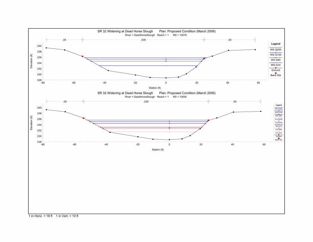
-80 -60 -40 -20 0 20 40 60228
230
232
234
236
238
240
SR 32 Widening at Dead Horse Slough Plan: Proposed Condition (March 2006)River = DeadHorseSlough Reach = 1 RS = 10076
Station (ft)
Ele
vatio
n (ft
)
Legend
WS Q200
WS Q100
WS Q50
WS Q10
Ground
Bank Sta
.05 .035 .05
-80 -60 -40 -20 0 20 40 60228
230
232
234
236
238
240
SR 32 Widening at Dead Horse Slough Plan: Proposed Condition (March 2006)River = DeadHorseSlough Reach = 1 RS = 10000
Station (ft)
Ele
vatio
n (ft
)
Legend
WS Q200
WS Q100
WS Q50
Crit Q200
Crit Q100
WS Q10
Crit Q50
Crit Q10
Ground
Bank Sta
.05 .035 .05
1 in Horiz. = 18 ft 1 in Vert. = 10 ft

SR 32 Widening over Dead Horse Slough and South Fork Dead Horse Slough
City of Chico Appendix B – HEC-RAS Proposed Condition
Draft Bridge Design Hydraulic Study August 2006
HEC-RAS Version 3.1.3 May 2005 U.S. Army Corp of Engineers Hydrologic Engineering Center 609 Second Street Davis, California X X XXXXXX XXXX XXXX XX XXXX X X X X X X X X X X X X X X X X X X X XXXXXXX XXXX X XXX XXXX XXXXXX XXXX X X X X X X X X X X X X X X X X X X X X X XXXXXX XXXX X X X X XXXXX PROJECT DATA Project Title: SR 32 Widening at Dead Horse Slough Project File : DeadHorse.prj Run Date and Time: 3/6/2006 3:12:01 PM Project in English units PLAN DATA Plan Title: Proposed Condition (March 2006) Plan File : g:\Projects\Y2005\P0513 SR32 Chico\HEC-RAS\Dead Horse Slough\DeadHorse.p04 Geometry Title: Prop Widen Bridge (Feb 2006) Geometry File : g:\Projects\Y2005\P0513 SR32 Chico\HEC-RAS\Dead Horse Slough\DeadHorse.g02 Flow Title : City of Chico Q - Normal Depth Flow File : g:\Projects\Y2005\P0513 SR32 Chico\HEC-RAS\Dead Horse Slough\DeadHorse.f02 Plan Summary Information: Number of: Cross Sections = 9 Multiple Openings = 0 Culverts = 0 Inline Structures = 0 Bridges = 1 Lateral Structures = 0 Computational Information Water surface calculation tolerance = 0.01 Critical depth calculation tolerance = 0.01 Maximum number of iterations = 20 Maximum difference tolerance = 0.3 Flow tolerance factor = 0.001 Computation Options Critical depth computed only where necessary Conveyance Calculation Method: At breaks in n values only Friction Slope Method: Average Conveyance Computational Flow Regime: Subcritical Flow FLOW DATA Flow Title: City of Chico Q - Normal Depth Flow File : g:\Projects\Y2005\P0513 SR32 Chico\HEC-RAS\Dead Horse Slough\DeadHorse.f02 Flow Data (cfs) River Reach RS Q200 Q100 Q50 Q10 DeadHorseSlough 1 10882 2220 1900 1500 750 Boundary Conditions River Reach Profile Upstream Downstream DeadHorseSlough 1 Q200 Normal S = 0.0057 Normal S = 0.0025 DeadHorseSlough 1 Q100 Normal S = 0.0057 Normal S = 0.0025 DeadHorseSlough 1 Q50 Normal S = 0.0057 Normal S = 0.0025 DeadHorseSlough 1 Q10 Normal S = 0.0057 Normal S = 0.0025 GEOMETRY DATA Geometry Title: Prop Widen Bridge (Feb 2006) Geometry File : g:\Projects\Y2005\P0513 SR32 Chico\HEC-RAS\Dead Horse Slough\DeadHorse.g02 CROSS SECTION RIVER: DeadHorseSlough REACH: 1 RS: 10882

SR 32 Widening over Dead Horse Slough and South Fork Dead Horse Slough
City of Chico Appendix B – HEC-RAS Proposed Condition
Draft Bridge Design Hydraulic Study August 2006
INPUT Description: Station Elevation Data num= 8 Sta Elev Sta Elev Sta Elev Sta Elev Sta Elev -45.85 240.38 -34.7 235.6 -24.35 235.21 -13.75 232.68 -5.94 231.15 0 230.98 12.78 231.74 14.7 238.67 Manning's n Values num= 3 Sta n Val Sta n Val Sta n Val -45.85 .05 -45.85 .035 14.7 .05 Bank Sta: Left Right Lengths: Left Channel Right Coeff Contr. Expan. -45.85 14.7 90 90 90 .1 .3 CROSS SECTION RIVER: DeadHorseSlough REACH: 1 RS: 10792 INPUT Description: Station Elevation Data num= 17 Sta Elev Sta Elev Sta Elev Sta Elev Sta Elev -47.07 240.51 -41.44 240.12 -25.33 233.7 -21.91 233.18 -16.29 233.97 -9.47 233.44 -5.81 232.33 -3.65 231.35 0 231.13 4.87 231.83 12.33 231.62 15.91 232.67 21.8 232.53 23.51 231.84 26.55 232.22 39.81 238.45 57.46 240.43 Manning's n Values num= 3 Sta n Val Sta n Val Sta n Val -47.07 .05 -41.44 .035 39.81 .05 Bank Sta: Left Right Lengths: Left Channel Right Coeff Contr. Expan. -41.44 39.81 30 30 30 .1 .3 CROSS SECTION RIVER: DeadHorseSlough REACH: 1 RS: 10762.* INPUT Description: Station Elevation Data num= 24 Sta Elev Sta Elev Sta Elev Sta Elev Sta Elev -49.14 240.72 -45.29 240.45 -40.18 238.54 -29.44 233.9 -27.68 233.39 -23.95 232.89 -17.8 233.18 -16.4 233.06 -10.43 232.78 -10.35 232.78 -6.35 232.06 -3.99 231.42 -2.87 231.39 0 231.03 4.5 231.73 7.68 231.82 11.39 231.69 14.69 232.36 17.34 232.28 20.13 232.59 21.71 232.31 24.52 232.93 36.77 238.75 55.03 240.2 Manning's n Values num= 3 Sta n Val Sta n Val Sta n Val -49.14 .045 -45.29 .04 36.77 .05 Bank Sta: Left Right Lengths: Left Channel Right Coeff Contr. Expan. -45.29 36.77 118 118 118 .3 .5 BRIDGE RIVER: DeadHorseSlough REACH: 1 RS: 10758 INPUT Description: SR 32 at Dead Horse Slough (45 degree skew) Distance from Upstream XS = 3.5 Deck/Roadway Width = 111 Weir Coefficient = 2.6 Upstream Deck/Roadway Coordinates num= 6 Sta Hi Cord Lo Cord Sta Hi Cord Lo Cord Sta Hi Cord Lo Cord -350 244 0 -53.65 242.98 0 -53.64 242.98 241.01 33.86 242.68 240.71 33.87 242.68 0 145 242.3 0 Upstream Bridge Cross Section Data Station Elevation Data num= 24 Sta Elev Sta Elev Sta Elev Sta Elev Sta Elev -49.14 240.72 -45.29 240.45 -40.18 238.54 -29.44 233.9 -27.68 233.39 -23.95 232.89 -17.8 233.18 -16.4 233.06 -10.43 232.78 -10.35 232.78 -6.35 232.06 -3.99 231.42 -2.87 231.39 0 231.03 4.5 231.73 7.68 231.82 11.39 231.69 14.69 232.36 17.34 232.28 20.13 232.59 21.71 232.31 24.52 232.93 36.77 238.75 55.03 240.2 Manning's n Values num= 3 Sta n Val Sta n Val Sta n Val -49.14 .045 -45.29 .04 36.77 .05 Bank Sta: Left Right Coeff Contr. Expan. -45.29 36.77 .3 .5 Downstream Deck/Roadway Coordinates

SR 32 Widening over Dead Horse Slough and South Fork Dead Horse Slough
City of Chico Appendix B – HEC-RAS Proposed Condition
Draft Bridge Design Hydraulic Study August 2006
num= 6 Sta Hi Cord Lo Cord Sta Hi Cord Lo Cord Sta Hi Cord Lo Cord -350 244 0 -55.52 242.98 0 -55.51 242.98 240.79 31.99 242.68 240.49 32 242.68 0 145 242.3 0 Downstream Bridge Cross Section Data Station Elevation Data num= 13 Sta Elev Sta Elev Sta Elev Sta Elev Sta Elev -68.66 240.95 -51.07 239.13 -46.21 238.41 -37.75 234.02 -27.51 232.99 -22.26 231.14 -17.86 230.45 -7.97 231.19 0 230.18 6.96 232.01 14.15 233.23 26.82 236.44 31.99 238.69 Manning's n Values num= 3 Sta n Val Sta n Val Sta n Val -68.66 .05 -46.21 .035 31.99 .05 Bank Sta: Left Right Coeff Contr. Expan. -46.21 31.99 .1 .3 Upstream Embankment side slope = 0 horiz. to 1.0 vertical Downstream Embankment side slope = 0 horiz. to 1.0 vertical Maximum allowable submergence for weir flow = .95 Elevation at which weir flow begins = Energy head used in spillway design = Spillway height used in design = Weir crest shape = Broad Crested Number of Abutments = 2 Abutment Data Upstream num= 2 Sta Elev Sta Elev -63.64 243.014 -53.64 242.98 Downstream num= 2 Sta Elev Sta Elev -65.51 243.014 -55.51 242.98 Abutment Data Upstream num= 2 Sta Elev Sta Elev 33.86 242.68 43.86 242.646 Downstream num= 2 Sta Elev Sta Elev 31.99 242.68 41.99 242.646 Number of Piers = 3 Pier Data Pier Station Upstream= -31.77 Downstream= -33.64 Upstream num= 2 Width Elev Width Elev 1.5 0 1.5 242 Downstream num= 2 Width Elev Width Elev 1.5 0 1.5 242 Pier Data Pier Station Upstream= -9.895 Downstream= -11.765 Upstream num= 2 Width Elev Width Elev 1.5 0 1.5 242 Downstream num= 2 Width Elev Width Elev 1.5 0 1.5 242 Pier Data Pier Station Upstream= 11.98 Downstream= 10.11 Upstream num= 2 Width Elev Width Elev 1.5 0 1.5 242 Downstream num= 2 Width Elev Width Elev 1.5 0 1.5 242 Number of Bridge Coefficient Sets = 1 Low Flow Methods and Data Energy Selected Low Flow Methods = Highest Energy Answer High Flow Method Energy Only Additional Bridge Parameters Add Friction component to Momentum Do not add Weight component to Momentum Class B flow critical depth computations use critical depth inside the bridge at the upstream end Criteria to check for pressure flow = Upstream energy grade line CROSS SECTION RIVER: DeadHorseSlough

SR 32 Widening over Dead Horse Slough and South Fork Dead Horse Slough
City of Chico Appendix B – HEC-RAS Proposed Condition
Draft Bridge Design Hydraulic Study August 2006
REACH: 1 RS: 10644 INPUT Description: Station Elevation Data num= 13 Sta Elev Sta Elev Sta Elev Sta Elev Sta Elev -68.66 240.95 -51.07 239.13 -46.21 238.41 -37.75 234.02 -27.51 232.99 -22.26 231.14 -17.86 230.45 -7.97 231.19 0 230.18 6.96 232.01 14.15 233.23 26.82 236.44 31.99 238.69 Manning's n Values num= 3 Sta n Val Sta n Val Sta n Val -68.66 .05 -46.21 .035 31.99 .05 Bank Sta: Left Right Lengths: Left Channel Right Coeff Contr. Expan. -46.21 31.99 132 132 132 .1 .3 CROSS SECTION RIVER: DeadHorseSlough REACH: 1 RS: 10512 INPUT Description: Station Elevation Data num= 9 Sta Elev Sta Elev Sta Elev Sta Elev Sta Elev -23.36 237.75 -13.06 233.26 -5.54 231.44 0 230.62 11.45 230.89 12.39 231.31 38.84 232.44 49.31 237.73 62.31 237.71 Manning's n Values num= 3 Sta n Val Sta n Val Sta n Val -23.36 .05 -23.36 .035 49.31 .05 Bank Sta: Left Right Lengths: Left Channel Right Coeff Contr. Expan. -23.36 49.31 250 250 250 .1 .3 CROSS SECTION RIVER: DeadHorseSlough REACH: 1 RS: 10262 INPUT Description: Station Elevation Data num= 12 Sta Elev Sta Elev Sta Elev Sta Elev Sta Elev -59.16 238.08 -46.79 237.31 -32.38 232.4 -26.49 229.96 -22.55 230.99 -19.22 231.18 -15.49 230.59 -5.86 229.4 0 229.24 7.63 229.78 12.22 231.24 30.47 237.79 Manning's n Values num= 3 Sta n Val Sta n Val Sta n Val -59.16 .05 -46.79 .035 30.47 .05 Bank Sta: Left Right Lengths: Left Channel Right Coeff Contr. Expan. -46.79 30.47 154 154 154 .1 .3 CROSS SECTION RIVER: DeadHorseSlough REACH: 1 RS: 10108 INPUT Description: Station Elevation Data num= 12 Sta Elev Sta Elev Sta Elev Sta Elev Sta Elev -70.32 238.76 -58.4 238.35 -51.96 236.51 -45.02 234.06 -35 231.04 -29.44 229.34 -22.42 229.77 -11.16 229.32 0 229.04 8.11 229.05 11.61 231.56 27.83 238.68 Manning's n Values num= 3 Sta n Val Sta n Val Sta n Val -70.32 .05 -51.96 .035 27.83 .05 Bank Sta: Left Right Lengths: Left Channel Right Coeff Contr. Expan. -51.96 27.83 32 32 32 .1 .3 CROSS SECTION RIVER: DeadHorseSlough REACH: 1 RS: 10076 INPUT Description: Station Elevation Data num= 14 Sta Elev Sta Elev Sta Elev Sta Elev Sta Elev -77.78 239.26 -65.83 238.53 -54.27 236.29 -37.51 231.3 -19.86 229.76 -10.37 228.88 0 228.74 8.05 229.02 13.18 230.13 19.49 232.56 24.73 235.54 30.04 236.37 40.56 238.41 57.87 238.66 Manning's n Values num= 3

SR 32 Widening over Dead Horse Slough and South Fork Dead Horse Slough
City of Chico Appendix B – HEC-RAS Proposed Condition
Draft Bridge Design Hydraulic Study August 2006
Sta n Val Sta n Val Sta n Val -77.78 .05 -54.27 .035 24.73 .05 Bank Sta: Left Right Lengths: Left Channel Right Coeff Contr. Expan. -54.27 24.73 76 76 76 .1 .3 CROSS SECTION RIVER: DeadHorseSlough REACH: 1 RS: 10000 INPUT Description: Station Elevation Data num= 14 Sta Elev Sta Elev Sta Elev Sta Elev Sta Elev -77.78 239.26 -65.83 238.53 -54.27 236.29 -37.51 231.3 -19.86 229.76 -10.37 228.88 0 228.74 8.05 229.02 13.18 230.13 19.49 232.56 24.73 235.54 30.04 236.37 40.56 238.41 57.87 238.66 Manning's n Values num= 3 Sta n Val Sta n Val Sta n Val -77.78 .05 -54.27 .035 24.73 .05 Bank Sta: Left Right Lengths: Left Channel Right Coeff Contr. Expan. -54.27 24.73 0 0 0 .1 .3 SUMMARY OF MANNING'S N VALUES River:DeadHorseSlough Reach River Sta. n1 n2 n3 1 10882 .05 .035 .05 1 10792 .05 .035 .05 1 10762.* .045 .04 .05 1 10758 Bridge 1 10644 .05 .035 .05 1 10512 .05 .035 .05 1 10262 .05 .035 .05 1 10108 .05 .035 .05 1 10076 .05 .035 .05 1 10000 .05 .035 .05 SUMMARY OF REACH LENGTHS River: DeadHorseSlough Reach River Sta. Left Channel Right 1 10882 90 90 90 1 10792 30 30 30 1 10762.* 118 118 118 1 10758 Bridge 1 10644 132 132 132 1 10512 250 250 250 1 10262 154 154 154 1 10108 32 32 32 1 10076 76 76 76 1 10000 0 0 0 SUMMARY OF CONTRACTION AND EXPANSION COEFFICIENTS River: DeadHorseSlough Reach River Sta. Contr. Expan. 1 10882 .1 .3 1 10792 .1 .3 1 10762.* .3 .5 1 10758 Bridge 1 10644 .1 .3 1 10512 .1 .3 1 10262 .1 .3 1 10108 .1 .3 1 10076 .1 .3 1 10000 .1 .3

1
1721.56
1681.42
1485.701450
1320.66*
1163.75
1000
900
SoF
ork
DeadH
orse
Chris_Sewell
PROPOSED CONDITION HEC-RAS MODEL
Chris_Sewell
DRAFT BRIDGE DESIGN HYDRAULIC STUDY REPORT FOR THE SOUTH FORK DEAD HORSE SLOUGH CULVERT UNDER SR32 CITY OF CHICO, CALIFORNIA

HEC-RAS Plan: PrAug06 River: SoFork DeadHorse Reach: 1Reach River Sta Profile Q Total Min Ch El W.S. Elev Crit W.S. E.G. Elev E.G. Slope Vel Chnl Flow Area Top Width Froude # Chl
(cfs) (ft) (ft) (ft) (ft) (ft/ft) (ft/s) (sq ft) (ft) 1 1721.56 Q100 466.00 248.16 254.54 254.59 0.000158 1.65 282.99 64.89 0.141 1721.56 Q50 431.00 248.16 254.13 254.17 0.000179 1.68 256.71 61.75 0.151 1721.56 Q25 361.00 248.16 253.26 253.31 0.000238 1.76 205.07 57.10 0.161 1721.56 Q10 290.00 248.16 252.32 252.38 0.000352 1.88 153.96 52.10 0.19
1 1681.42 Q100 466.00 247.97 254.52 254.58 0.000230 1.88 249.82 69.24 0.161 1681.42 Q50 431.00 247.97 254.10 254.16 0.000276 1.94 222.29 61.61 0.181 1681.42 Q25 361.00 247.97 253.22 253.29 0.000402 2.10 172.07 54.17 0.211 1681.42 Q10 290.00 247.97 252.27 252.35 0.000637 2.35 123.50 46.42 0.25
1 1485.70 Q100 466.00 246.30 254.55 248.44 254.56 0.000010 0.54 1486.17 522.73 0.041 1485.70 Q50 431.00 246.30 254.13 248.37 254.14 0.000012 0.57 1268.91 502.45 0.041 1485.70 Q25 361.00 246.30 253.26 248.23 253.26 0.000018 0.64 869.77 409.01 0.051 1485.70 Q10 290.00 246.30 252.31 248.07 252.32 0.000029 0.70 532.62 287.42 0.06
1 1450 Culvert
1 1320.66* Q100 466.00 243.94 249.23 249.35 0.000653 2.92 208.94 92.86 0.271 1320.66* Q50 431.00 243.94 248.60 248.77 0.001103 3.48 154.39 79.76 0.341 1320.66* Q25 361.00 243.94 248.05 248.25 0.001509 3.72 113.60 68.35 0.391 1320.66* Q10 290.00 243.94 247.58 247.79 0.001831 3.74 83.61 58.50 0.42
1 1163.75 Q100 466.00 243.40 248.98 249.20 0.001165 3.90 142.20 64.92 0.361 1163.75 Q50 431.00 243.40 248.15 248.51 0.002319 4.86 95.76 46.90 0.491 1163.75 Q25 361.00 243.40 247.42 247.87 0.003775 5.39 67.42 31.14 0.601 1163.75 Q10 290.00 243.40 246.44 246.31 247.18 0.009582 6.90 42.04 23.70 0.91
1 1000 Q100 466.00 242.35 248.93 249.04 0.000541 2.65 189.17 58.98 0.211 1000 Q50 431.00 242.35 248.08 248.22 0.000867 3.04 144.97 44.94 0.271 1000 Q25 361.00 242.35 247.32 247.47 0.001135 3.13 115.48 33.32 0.301 1000 Q10 290.00 242.35 246.15 246.36 0.002226 3.69 78.54 29.66 0.40
1 900 Q100 1900.00 241.60 248.21 246.27 248.83 0.002231 6.34 299.66 65.17 0.521 900 Q50 1500.00 241.60 247.46 245.72 248.01 0.002263 5.95 252.27 61.21 0.521 900 Q25 1200.00 241.60 246.72 245.25 247.23 0.002498 5.76 208.41 57.30 0.531 900 Q10 750.00 241.60 245.76 244.44 246.12 0.002260 4.81 155.84 52.23 0.49

0 200 400 600 800
240
245
250
255
260
265
SR 32 at South Fork Dead Horse Slough Plan: Proposed Condition (August 2006)
Main Channel Distance (ft)
Ele
vatio
n (ft
)
Legend
WS Q100
WS Q50
WS Q25
Crit Q100
WS Q10
Crit Q50
Crit Q25
Crit Q10
Ground
LOB
ROB
900
1000
1163
.75
1320
.66*
1450
1485
.70
1681
.42
1721
.56
SoFork DeadHorse 1
1 in Horiz. = 120 ft 1 in Vert. = 5 ft

0 100 200 300 400 500248
250
252
254
256
258
260
262
SR 32 at South Fork Dead Horse Slough Plan: Proposed Condition (August 2006)River = SoFork DeadHorse Reach = 1 RS = 1721.56
Station (ft)
Ele
vatio
n (ft
)
Legend
WS Q100
WS Q50
WS Q25
WS Q10
Ground
Bank Sta
.045 .03 .045
0 100 200 300 400 500246
248
250
252
254
256
258
260
SR 32 at South Fork Dead Horse Slough Plan: Proposed Condition (August 2006)River = SoFork DeadHorse Reach = 1 RS = 1681.42
Station (ft)
Ele
vatio
n (ft
)
Legend
WS Q100
WS Q50
WS Q25
WS Q10
Ground
Bank Sta
.045 .03 .045
-100 0 100 200 300 400 500246
248
250
252
254
256
258
260
SR 32 at South Fork Dead Horse Slough Plan: Proposed Condition (August 2006)River = SoFork DeadHorse Reach = 1 RS = 1485.70
Station (ft)
Ele
vatio
n (ft
)
Legend
WS Q100
WS Q50
WS Q25
WS Q10
Crit Q100
Crit Q50
Crit Q25
Crit Q10
Ground
Bank Sta
.045 .03 .045
1 in Horiz. = 75 ft 1 in Vert. = 12 ft

-100 0 100 200 300 400 500246
248
250
252
254
256
258
260
SR 32 at South Fork Dead Horse Slough Plan: Proposed Condition (August 2006)River = SoFork DeadHorse Reach = 1 RS = 1450 Culv
Station (ft)
Ele
vatio
n (ft
)
Legend
WS Q100
Crit Q100
WS Q50
Crit Q50
WS Q25
Crit Q25
WS Q10
Crit Q10
Ground
Bank Sta
.045 .03 .045
0 100 200 300 400 500242
244
246
248
250
252
254
256
SR 32 at South Fork Dead Horse Slough Plan: Proposed Condition (August 2006)River = SoFork DeadHorse Reach = 1 RS = 1450 Culv
Station (ft)
Ele
vatio
n (ft
)
Legend
Crit Q100
Crit Q50
Crit Q25
Crit Q10
WS Q100
WS Q50
WS Q25
WS Q10
Ground
Bank Sta
.045 .03 .045
0 100 200 300 400 500242
244
246
248
250
252
254
256
SR 32 at South Fork Dead Horse Slough Plan: Proposed Condition (August 2006)River = SoFork DeadHorse Reach = 1 RS = 1320.66*
Station (ft)
Ele
vatio
n (ft
)
Legend
WS Q100
WS Q50
WS Q25
WS Q10
Ground
Bank Sta
.045 .03 .045
1 in Horiz. = 75 ft 1 in Vert. = 12 ft

0 100 200 300 400 500242
244
246
248
250
252
254
256
SR 32 at South Fork Dead Horse Slough Plan: Proposed Condition (August 2006)River = SoFork DeadHorse Reach = 1 RS = 1163.75
Station (ft)
Ele
vatio
n (ft
)
Legend
WS Q100
WS Q50
WS Q25
WS Q10
Crit Q10
Ground
Bank Sta
.045 .03 .045
0 100 200 300 400 500242
244
246
248
250
252
254
256
SR 32 at South Fork Dead Horse Slough Plan: Proposed Condition (August 2006)River = SoFork DeadHorse Reach = 1 RS = 1000
Station (ft)
Ele
vatio
n (ft
)
Legend
WS Q100
WS Q50
WS Q25
WS Q10
Ground
Bank Sta
.045 .035 .045
0 100 200 300 400 500240
242
244
246
248
250
252
254
SR 32 at South Fork Dead Horse Slough Plan: Proposed Condition (August 2006)River = SoFork DeadHorse Reach = 1 RS = 900
Station (ft)
Ele
vatio
n (ft
)
Legend
WS Q100
WS Q50
WS Q25
Crit Q100
WS Q10
Crit Q50
Crit Q25
Crit Q10
Ground
Bank Sta
.045 .03 .045
1 in Horiz. = 75 ft 1 in Vert. = 12 ft

SR 32 Widening over Dead Horse Slough and South Fork Dead Horse Slough
City of Chico Appendix E – Scour Analysis Calculations
Draft Bridge Design Hydraulic Study August 2006
HEC-RAS Version 3.1.3 May 2005 U.S. Army Corp of Engineers Hydrologic Engineering Center 609 Second Street Davis, California X X XXXXXX XXXX XXXX XX XXXX X X X X X X X X X X X X X X X X X X X XXXXXXX XXXX X XXX XXXX XXXXXX XXXX X X X X X X X X X X X X X X X X X X X X X XXXXXX XXXX X X X X XXXXX PROJECT DATA Project Title: SR 32 at South Fork Dead Horse Slough Project File : SFDeadHorse.prj Run Date and Time: 8/14/2006 10:06:44 AM Project in English units PLAN DATA Plan Title: Proposed Condition (August 2006) Plan File : g:\Projects\Y2005\P0513 SR32 Chico\HEC-RAS\South Fork Dead Horse Slough\SFDeadHorse.p08 Geometry Title: WRECO Proposed revised2 Geometry File : g:\Projects\Y2005\P0513 SR32 Chico\HEC-RAS\South Fork Dead Horse Slough\SFDeadHorse.g05 Flow Title : City of Chico-Husa Ranch Development WSE Flow File : g:\Projects\Y2005\P0513 SR32 Chico\HEC-RAS\South Fork Dead Horse Slough\SFDeadHorse.f01 Plan Summary Information: Number of: Cross Sections = 7 Multiple Openings = 0 Culverts = 1 Inline Structures = 0 Bridges = 0 Lateral Structures = 0 Computational Information Water surface calculation tolerance = 0.01 Critical depth calculation tolerance = 0.01 Maximum number of iterations = 20 Maximum difference tolerance = 0.3 Flow tolerance factor = 0.001 Computation Options Critical depth computed only where necessary Conveyance Calculation Method: At breaks in n values only Friction Slope Method: Average Conveyance Computational Flow Regime: Subcritical Flow FLOW DATA Flow Title: City of Chico-Husa Ranch Development WSE Flow File : g:\Projects\Y2005\P0513 SR32 Chico\HEC-RAS\South Fork Dead Horse Slough\SFDeadHorse.f01 Flow Data (cfs) River Reach RS Q200 Q100 Q50 Q25 Q10 SoFork DeadHorse1 1721.56 528 466 431 361 290 SoFork DeadHorse1 900 2220 1900 1500 1200 750 Boundary Conditions River Reach Profile Upstream Downstream SoFork DeadHorse1 Q200 Normal S = 0.011 Known WS = 248.75 SoFork DeadHorse1 Q100 Normal S = 0.011 Known WS = 248.21 SoFork DeadHorse1 Q50 Normal S = 0.011 Known WS = 247.46 SoFork DeadHorse1 Q25 Normal S = 0.011 Known WS = 246.72 SoFork DeadHorse1 Q10 Normal S = 0.011 Known WS = 245.76 GEOMETRY DATA Geometry Title: WRECO Proposed revised2 Geometry File : g:\Projects\Y2005\P0513 SR32 Chico\HEC-RAS\South Fork Dead Horse Slough\SFDeadHorse.g05 CROSS SECTION RIVER: SoFork DeadHorse REACH: 1 RS: 1721.56 INPUT Description: Station Elevation Data num= 9 Sta Elev Sta Elev Sta Elev Sta Elev Sta Elev -72.65 262.13 -53.81 262.41 -40.03 256.05 -19.63 248.38 -15.67 248.16 -2.79 248.56 14.78 249.64 27.79 254.48 56.98 256.2 Manning's n Values num= 3 Sta n Val Sta n Val Sta n Val -72.65 .045 -53.81 .03 27.79 .045

SR 32 Widening over Dead Horse Slough and South Fork Dead Horse Slough
City of Chico Appendix E – Scour Analysis Calculations
Draft Bridge Design Hydraulic Study August 2006
Bank Sta: Left Right Lengths: Left Channel Right Coeff Contr. Expan. -53.81 27.79 40.14 40.14 40.14 .1 .3 CROSS SECTION RIVER: SoFork DeadHorse REACH: 1 RS: 1681.42 INPUT Description: Station Elevation Data num= 13 Sta Elev Sta Elev Sta Elev Sta Elev Sta Elev -65.21 261.92 -43.87 260.62 -19.98 249.99 -16.32 249.08 -14.92 248.3 -9.66 247.97 -4.74 248.03 -4.1 248.74 12.53 249.87 18.47 252.04 23.71 252.46 30 253.95 55.55 255.56 Manning's n Values num= 3 Sta n Val Sta n Val Sta n Val -65.21 .045 -43.87 .03 30 .045 Bank Sta: Left Right Lengths: Left Channel Right Coeff Contr. Expan. -43.87 30 195.72 195.72 195.72 .1 .3 CROSS SECTION RIVER: SoFork DeadHorse REACH: 1 RS: 1485.70 INPUT Description: Station Elevation Data num= 14 Sta Elev Sta Elev Sta Elev Sta Elev Sta Elev -82.78 256.91 -38 252.26 -23.73 247.2 -18.78 247.57 -14.58 246.63 -8.13 246.3 -2.99 246.3 .93 247.01 28.28 247.79 48.76 249.86 74.65 250.57 97.65 251.4 297.65 252.6 462.65 254.3 Manning's n Values num= 3 Sta n Val Sta n Val Sta n Val -82.78 .045 -38 .03 48.76 .045 Bank Sta: Left Right Lengths: Left Channel Right Coeff Contr. Expan. -38 48.76 165.04 165.04 165.04 .3 .5 CULVERT RIVER: SoFork DeadHorse REACH: 1 RS: 1450 INPUT Description: Distance from Upstream XS = 23.5 Deck/Roadway Width = 141.5 Weir Coefficient = 2.6 Upstream Deck/Roadway Coordinates num= 5 Sta Hi Cord Lo Cord Sta Hi Cord Lo Cord Sta Hi Cord Lo Cord -233 255.3 0 -120 255.5 0 128 256.3 0 271 256.6 0 470 259.1 0 Upstream Bridge Cross Section Data Station Elevation Data num= 14 Sta Elev Sta Elev Sta Elev Sta Elev Sta Elev -82.78 256.91 -38 252.26 -23.73 247.2 -18.78 247.57 -14.58 246.63 -8.13 246.3 -2.99 246.3 .93 247.01 28.28 247.79 48.76 249.86 74.65 250.57 97.65 251.4 297.65 252.6 462.65 254.3 Manning's n Values num= 3 Sta n Val Sta n Val Sta n Val -82.78 .045 -38 .03 48.76 .045 Bank Sta: Left Right Coeff Contr. Expan. -38 48.76 .3 .5 Downstream Deck/Roadway Coordinates num= 4 Sta Hi Cord Lo Cord Sta Hi Cord Lo Cord Sta Hi Cord Lo Cord -233 255.3 0 -120 255.5 0 128 256.3 0 271 256.6 0 Downstream Bridge Cross Section Data Station Elevation Data num= 17 Sta Elev Sta Elev Sta Elev Sta Elev Sta Elev -43.42 253.48 -23.8 253.2 -4.22 250.38 3.65 247.75 6.5 246.9 10.78 244.69 12.22 244.48 14.48 244.12 15.82 243.94 22.25 244.15 23.75 244.39 31.11 245.67 35.68 247.27 57.64 247.29 91.66 249.21 94.53 249.37 131.42 250 Manning's n Values num= 3 Sta n Val Sta n Val Sta n Val -43.42 .045 -4.22 .03 35.68 .045 Bank Sta: Left Right Coeff Contr. Expan. -4.22 35.68 .1 .3 Upstream Embankment side slope = 0 horiz. to 1.0 vertical Downstream Embankment side slope = 0 horiz. to 1.0 vertical Maximum allowable submergence for weir flow = .95 Elevation at which weir flow begins = Energy head used in spillway design = Spillway height used in design = Weir crest shape = Broad Crested Number of Culverts = 1

SR 32 Widening over Dead Horse Slough and South Fork Dead Horse Slough
City of Chico Appendix E – Scour Analysis Calculations
Draft Bridge Design Hydraulic Study August 2006
Culvert Name Shape Rise Span Culvert #1 Box 6 8 FHWA Chart # 11- Skewed headwall; Chamfered or beveled Inlet FHWA Scale # 3 - Headwall skewed 15 deg.; inlet edges chamfered 3/4 inch Solution Criteria = Highest U.S. EG Culvert Upstrm Dist Length Top n Bottom n Depth Blocked Entrance Loss Coef Exit Loss Coef 23.5 141.5 .013 .013 0 .5 1 Upstream Elevation = 246.29 Centerline Station = -6 Downstream Elevation = 243.32 Centerline Station = 20 CROSS SECTION RIVER: SoFork DeadHorse REACH: 1 RS: 1320.66* INPUT Description: Station Elevation Data num= 17 Sta Elev Sta Elev Sta Elev Sta Elev Sta Elev -43.42 253.48 -23.8 253.2 -4.22 250.38 3.65 247.75 6.5 246.9 10.78 244.69 12.22 244.48 14.48 244.12 15.82 243.94 22.25 244.15 23.75 244.39 31.11 245.67 35.68 247.27 57.64 247.29 91.66 249.21 94.53 249.37 131.42 250 Manning's n Values num= 3 Sta n Val Sta n Val Sta n Val -43.42 .045 -4.22 .03 35.68 .045 Bank Sta: Left Right Lengths: Left Channel Right Coeff Contr. Expan. -4.22 35.68 156.91 156.91 156.91 .1 .3 CROSS SECTION RIVER: SoFork DeadHorse REACH: 1 RS: 1163.75 INPUT Description: Station Elevation Data num= 10 Sta Elev Sta Elev Sta Elev Sta Elev Sta Elev -44.78 252.02 -22.68 250.59 -13.62 245.6 -3.75 244.27 -1.14 243.5 .4 243.4 4.23 244.14 9.99 247.21 45.18 248.98 70.18 250 Manning's n Values num= 3 Sta n Val Sta n Val Sta n Val -44.78 .045 -22.68 .03 9.99 .045 Bank Sta: Left Right Lengths: Left Channel Right Coeff Contr. Expan. -22.68 9.99 163.75 163.75 163.75 .1 .3 CROSS SECTION RIVER: SoFork DeadHorse REACH: 1 RS: 1000 INPUT Description: Station Elevation Data num= 12 Sta Elev Sta Elev Sta Elev Sta Elev Sta Elev -40.58 250.51 -21.47 250.19 6.33 250.35 15.5 244.97 20.41 242.97 25.61 242.35 28.86 242.52 32.12 243.23 39.18 243.34 44.89 247.38 66.19 248.84 85.19 250 Manning's n Values num= 3 Sta n Val Sta n Val Sta n Val -40.58 .045 6.33 .035 44.89 .045 Bank Sta: Left Right Lengths: Left Channel Right Coeff Contr. Expan. 6.33 44.89 100 100 100 .1 .3 CROSS SECTION RIVER: SoFork DeadHorse REACH: 1 RS: 900 INPUT Description: Station Elevation Data num= 10 Sta Elev Sta Elev Sta Elev Sta Elev Sta Elev -60.52 250.31 -35.8 250.75 -19.5 244.87 -8.77 242.14 0 241.6 12.8 241.75 18.19 242.52 23.87 243.21 39.8 249.56 64.03 252.38 Manning's n Values num= 3 Sta n Val Sta n Val Sta n Val -60.52 .045 -35.8 .03 39.8 .045 Bank Sta: Left Right Lengths: Left Channel Right Coeff Contr. Expan. -35.8 39.8 0 0 0 .1 .3 SUMMARY OF MANNING'S N VALUES River:SoFork DeadHorse Reach River Sta. n1 n2 n3 1 1721.56 .045 .03 .045 1 1681.42 .045 .03 .045 1 1485.70 .045 .03 .045 1 1450 Culvert

SR 32 Widening over Dead Horse Slough and South Fork Dead Horse Slough
City of Chico Appendix E – Scour Analysis Calculations
Draft Bridge Design Hydraulic Study August 2006
1 1320.66* .045 .03 .045 1 1163.75 .045 .03 .045 1 1000 .045 .035 .045 1 900 .045 .03 .045 SUMMARY OF REACH LENGTHS River: SoFork DeadHorse Reach River Sta. Left Channel Right 1 1721.56 40.14 40.14 40.14 1 1681.42 195.72 195.72 195.72 1 1485.70 165.04 165.04 165.04 1 1450 Culvert 1 1320.66* 156.91 156.91 156.91 1 1163.75 163.75 163.75 163.75 1 1000 100 100 100 1 900 0 0 0 SUMMARY OF CONTRACTION AND EXPANSION COEFFICIENTS River: SoFork DeadHorse Reach River Sta. Contr. Expan. 1 1721.56 .1 .3 1 1681.42 .1 .3 1 1485.70 .3 .5 1 1450 Culvert 1 1320.66* .1 .3 1 1163.75 .1 .3 1 1000 .1 .3 1 900 .1 .3

SR 32 Widening over Dead Horse Slough and South Fork Dead Horse Slough
City of Chico Appendix C – Proposed Bridge Plans
Draft Bridge Design Hydraulic Study August 2006
APPENDIX C
PROPOSED BRIDGE PLANS


SR 32 Widening over Dead Horse Slough and South Fork Dead Horse Slough
City of Chico Appendix D – Hydrologic Analyses
Draft Bridge Design Hydraulic Study August 2006
APPENDIX D
HYDROLOGIC ANALYSES


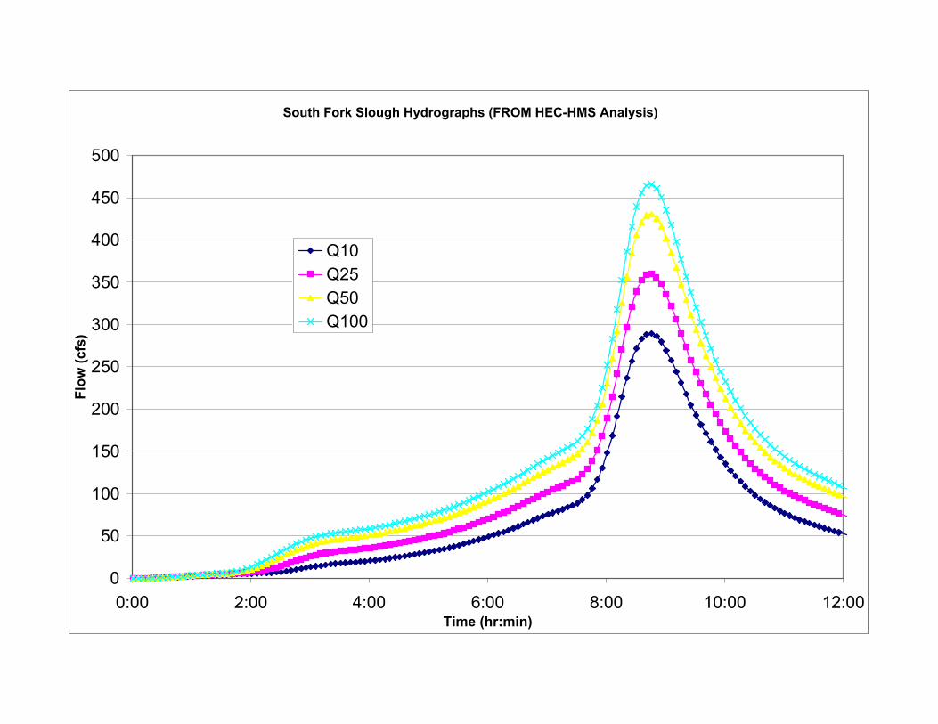
South Fork Slough Hydrographs (FROM HEC-HMS Analysis)
0
50
100
150
200
250
300
350
400
450
500
0:00 2:00 4:00 6:00 8:00 10:00 12:00Time (hr:min)
Flow
(cfs
)
Q10Q25Q50Q100

Catchment Name: Sheep Hollow Creek at Cohasset Road Bridge
Mean Annual Precipitation 28 inSource: OSU Corvallis, PRISM Project California Mean Annual Precipitation Plot
Topographic Parameterssq ft acres sq mi sq km
Size: 245,371,237 5,633 8.801482
Total flowline length 34,883 ft10% flowline length: 3,488 ftElevation at 10% flowline length 205 m85% flowline length: 29,651 ftElevation at 85% flowline length 910 mSource: "\Projects\Y2004\P0436 Cohasset\DWG\sheep hollow catchment.dwg"Based on USGS 7.5' quadrangle excerpted using TOPO! Software application
Average of 10% and 85% elevatio 558 mAltitude Index 1.83 ft * 1000
Discharges by Return PeriodQ2 0.24 0.88 1.58 -0.80 194 cfsQ5 1.20 0.82 1.37 -0.64 466 cfsQ10 2.63 0.80 1.25 -0.58 680 cfsQ25 6.55 0.79 1.12 -0.52 1,114 cfsQ50 10.40 0.78 1.06 -0.48 1,452 cfsQ100 15.70 0.77 1.02 -0.43 1,934 cfsSource: Caltrans Highway Design Manual, Figure 819.2C from USGS, "Magnitude and Frequency of Floods in California", June 1977.
Latitude LongitudeD M S DD Radians D M S DD Radians
Crossing Location: 39 47 11.8 39.78661 0.694407 121 50 37.9 -121.8439 -2.126577
Sierra Region Coefficients

CALIFORNIIA A N N U A L P R E C I P I T A T I O N S U M M A R Y (INCHES) | PRECIPITATION | SNOWFALL | NUMBER OF DAYS | | PERIOD OF | | MAX MIN MAX | MAX | >= >= >= >= | | RECORD | MEAN | YEAR YR YEAR YR DAY YEARMODY | MEAN YEAR YR | .01 .10 .50 1.0 | CHICO EXPERIMENT STN | 1906-2004 | 25.84 | 45.54 41 10.40 76 5.73 19160103 | 0.1 4.3 72 | 63 43 18 7 | http://www.wrcc.dri.edu/htmlfiles/ca/ca.ppt.ext.html


South Fork Slough Hydrographs (FROM HEC-HMS Analysis)
0
50
100
150
200
250
300
350
400
450
500
0:00 2:00 4:00 6:00 8:00 10:00 12:00Time (hr:min)
Flow
(cfs
)
Q10Q25Q50Q100

P0513: SR 32 WideningSouth Fork Dead Horse Slough Flows
From HEC-HMS AnalysisQ200 = 200 528.0017 cfs (FROM GRAPH)Q100 = 100 466 cfs (FROM HEC-HMS model)Q50 = 50 431 cfs (FROM HEC-HMS model)Q25 = 25 361 cfs (FROM HEC-HMS model)Q10 = 10 290 cfs (FROM HEC-HMS model)
Q200 = 200 528.0017 cfs (FROM GRAPH)
Figure 6: South Fork Dead Horse Slough Extrapolated Flows
y = 78.831Ln(x) + 110.33
200
250
300
350
400
450
500
550
10 100 1000
Return Period (years)
Flow
(cfs
) Series1Log. (Series1)


SR 32 Widening over Dead Horse Slough and South Fork Dead Horse Slough
City of Chico Appendix E – Scour Analysis Calculations
Draft Bridge Design Hydraulic Study August 2006
APPENDIX E
SCOUR ANALYSIS CALCULATIONS


SR 32 Widening over Dead Horse Slough and South Fork Dead Horse Slough
City of Chico Appendix E – Scour Analysis Calculations
Draft Bridge Design Hydraulic Study August 2006
Local Pier Scour – To determine pier scour, an equation based on the CSU equation is recommended within the HEC-18 manual for both live-bed and clear-water scour. The equation predicts maximum pier scour depths. The equation is:
where: Ys = Scour depth Y1 = Flow depth directly upstream of the pier K1 = Coefficient factor for pier nose shape (from HEC-18) K2 = Coefficient factor for angle of attack of flow (from HEC-18) K3 = Correction factor for bed condition (from HEC-18) K4 = Correction factor for armoring by bed material size (from HEC-18) a = Pier width V1 = Mean velocity of flow directly upstream of the pier Fr = Froude number directly upstream of the pier= V1/(gY1)0.5 After using HEC-RAS to analyze the flow at the proposed SR 32 Bridge at Dead Horse Slough, the factors in the above equation were determined to be:
Bridge Widening Bent 2 (HEC-RAS Pier #3) Y1 = 6.68 ft (from HEC-RAS) K1 = 1.0 (for round nose pier shape) (from HEC-18) K2 = 1.0 (for angle of attack = 0 degrees) (from HEC-18) K3 = 1.1 (for clear-water scour) (from HEC-18) K4 = 1.0 (for D50 < 2mm or D95 < 20mm) (from HEC-18) a = 3.75 ft.
Fr1 = 0.43 (from HEC-RAS) The Pier scour, calculated using the CSU equation is:
Ys = 7.02 ft Bent 3 (HEC-RAS Pier #2) Y1 = 5.79 ft (from HEC-RAS) K1 = 1.0 (for round nose pier shape) (from HEC-18) K2 = 1.0 (for angle of attack = 0 degrees) (from HEC-18) K3 = 1.1 (for clear-water scour) (from HEC-18) K4 = 1.0 (for D50 < 2mm or D95 < 20mm) (from HEC-18)
FrYa
KKKK.=YY 0.
21s 43
65.0
143
1
02
)43.0(68.675.3)0.1)(1.1)(0.1)(0.1(02
68.643
65.00.s .=Y

SR 32 Widening over Dead Horse Slough and South Fork Dead Horse Slough
City of Chico Appendix E – Scour Analysis Calculations
Draft Bridge Design Hydraulic Study August 2006
a = 3.75 ft. Fr1 = 0.43 (from HEC-RAS) The Pier scour, calculated using the CSU equation is:
Ys = 6.68 ft Bent 4 (HEC-RAS Pier #1) Y1 = 3.59 ft (from HEC-RAS) K1 = 1.0 (for round nose pier shape) (from HEC-18) K2 = 1.0 (for angle of attack = 0 degrees) (from HEC-18) K3 = 1.1 (for clear-water scour) (from HEC-18) K4 = 1.0 (for D50 < 2mm or D95 < 20mm) (from HEC-18) a = 3.75 ft.
Fr1 = 0.38 (from HEC-RAS) The Pier scour, calculated using the CSU equation is:
Ys = 5.35 ft Live-Bed Scour at abutments – As a check on the potential depth of scour to aid in the design of the foundation and placement of rock riprap and/or guide banks, either Froelich’s live-bed scour equation or the HIRE equation can be used. Use the live-bed equations even if clear-water scour dominates. Froelich’s Abutment Scour Equation is:
The HIRE Live-Bed Abutment Scour Equation is:
)43.0(79.575.3)0.1)(1.1)(0.1)(0.1(02
79.543
65.00.s .=Y
)38.0(59.375.3)0.1)(1.1)(0.1)(0.1(02
59.343
65.00.s .=Y
1272 6143.0
+
′Fr
YL
KK.=YY 0.
a21
a
s
55.0
4 133.0
1
kFr=YY s

SR 32 Widening over Dead Horse Slough and South Fork Dead Horse Slough
City of Chico Appendix E – Scour Analysis Calculations
Draft Bridge Design Hydraulic Study August 2006
where: Ys = Scour depth Ya = Average depth of flow on floodplain Y1 = Depth of flow at the abutment on the overbank or in the main channel K1 = Coefficient for abutment shape (from HEC-18) K2 = Coefficient for angle of embankment to flow (from HEC-18) L’ = Length of active flow obstructed by the embankment and abutment V1 = Hypothetical approach velocity of flow obstructed by embankment Fr = Froude number = V1/(gY1)0.5
The HIRE equation should be used when L’/Y1 is greater than 25; otherwise the Froelich equation applies. After using HEC-RAS to analyze the flow at the proposed SR 32 Bridge at Dead Horse Slough, the factors in the above equation were determined for each abutment to be: Bridge Widening Abutment 1 (HEC-RAS Right Abutment)
Ya = 1.04 ft (from HEC-RAS) Y1 = 1.12 ft (from HEC-RAS) L’ = 3.95 ft L’/Y1 = 3.95 ft / 1.12 ft < 25: therefore use Froelich’s equation K1 = 1.0 (vertical abutment) (from HEC-18) K2 = 1.0 (flow perpendicular to embankment) (from HEC-18) Fr1 = 0.36 (from HEC-RAS) The Abutment scour, calculated using Froelich’s equation is:
Ys = 3.31 ft Abutment 2 (Left Bank)
The 100-year water surface elevation does not reach Abutment 2 (HEC-RAS Left Abutment), and therefore, abutment scour was not evaluated at Abutment 2.
Clear-Water Contraction Scour - Contraction scour typically occurs where the bridge opening is smaller than the flow area of the upstream channel and/or flood plain. Clear-Water contraction scour occurs when there is little or no transport of bed material. Also use a Clear-Water Contraction Scour Equation if transported material is mostly suspended and will be washed through the contracted section reach. The Laursen’s Clear-Water Contraction Scour Equation can be used:
1)36.0(04.195.3)0.1)(0.1(272
04.161
43.0
+
0.s .=Y

SR 32 Widening over Dead Horse Slough and South Fork Dead Horse Slough
City of Chico Appendix E – Scour Analysis Calculations
Draft Bridge Design Hydraulic Study August 2006
where: Y2 = Average equilibrium depth in the contracted section (after scour) Dm = 1.25xD50 Q1 = Flow in the upstream channel transporting sediment Q = Flow in the contracted channel W = Bottom width of the contracted section (minus pier widths) KU = Exponent: 0.025 SI units, 0.0077 English Units (from HEC-18)
Live Bed Contraction Scour - Contraction scour typically occurs where the bridge opening is smaller than the flow area of the upstream channel and/or flood plain. Live-bed contraction scour occurs when there is transport of bed material in the upstream reach into the bridge cross section. With live bed contraction scour the area of the contracted section increases until, in the limit, the transport of sediment out of the contracted section equals the sediment transported in. The modified Laursen’s Live-Bed Contraction Scour Equation can be used:
where: Y2 = Average depth in the contracted section (after scour)
Y1 = Average depth in the upstream main channel Yo = Existing depth in the contracted section Q1 = Flow in the upstream channel transporting sediment Q2 = Flow in the contracted channel W1 = Bottom width of the upstream main channel W2 = Bottom width of the contracted section (minus pier widths)
The critical velocity equation is applied to determine whether Clear Water Contraction Scour or Live Bed Contraction Scour is occurring. If the flow velocity at the site is greater than the critical velocity, based on the average particle size present at the site, then the Live Bed Contraction Scour equation is used to determine scour.
where: VC = Critical velocity above which bed material of size D and smaller will be transported, m/s (ft/s)
y = Average depth of flow upstream of the bridge, m (ft)
73
232
2
2
=
WDQK
ym
U
os YY=Y −2
1
2
1
76
1
2
1
2k
WW
QQ=
YY
3/16/1 DyK=V UC

SR 32 Widening over Dead Horse Slough and South Fork Dead Horse Slough
City of Chico Appendix E – Scour Analysis Calculations
Draft Bridge Design Hydraulic Study August 2006
D = Particle size for VC, m (ft) D50 = Average particle size, m (ft)
KU = Exponent: 6.19 SI units, 11.17 English Units (from HEC-18) VC = 0.8 ft/s
After using HEC-RAS to analyze the flow at the proposed SR 32 Bridge at Dead Horse Slough, it is determined that Live Bed Contraction Scour is occurring. The factors for Laursen’s Live-Bed Contraction Scour Equation were determined to be: Bridge Widening Yo = 5.10 ft
Y1 = 5.01 ft Q1 = 2,200 cfs Q2 = 2,200 cfs W1 = 77.35 ft
W2 = 69.07 ft K1 = 0.69
The live-bed contraction scour calculated using Laursen’s Equation is:
Long Term Bed Elevation Change (long-term scour) – Long-term bed elevation change is the trend of a reach of stream bed to degrade or aggrade. The purpose of the evaluation is to estimate the changes that will occur during the life of the structure. A long term trend may change during the life of the bridge. These long-term changes are the result of modifications to the stream or watershed. Such changes may be a result of natural processes or human activities. The equation for evaluating long term bed change is:
21
21
AAEE=
−−
∆
3/16/1 )00016.0()01.5(17.11=VC
69.0762
07.6935.77
22002200
01.5
=Y
42.52 =Y
10.542.5 −=Ys
32.0=Ys ft

SR 32 Widening over Dead Horse Slough and South Fork Dead Horse Slough
City of Chico Appendix E – Scour Analysis Calculations
Draft Bridge Design Hydraulic Study August 2006
where: ∆ = long-term bed elevation change per year (ft/yr)
E1 = bed elevation in year x (ft) E2 = bed elevation in year y (ft) A1 = year x A2 = year y
Our field observations did not indicate severe creek bed degradation. We assumed the long-term bed elevation change to be negligible. Further research will be done to finalize our long-term bed change analysis. These results will be determined in the final version of this report.

SR 32 Widening over Dead Horse Slough and South Fork Dead Horse Slough
City of Chico Appendix E – Scour Analysis Calculations
Draft Bridge Design Hydraulic Study August 2006
From the Caltrans Highway Design Manual (1995, with updates)

Related Documents