Draft Environmental Impact Statement (EIS)/Environmental Impact Report (EIR) US Army Corps of Engineers Corte Madera Creek Flood Risk Management Project October 2018 APPENDIX I Civil Design

Welcome message from author
This document is posted to help you gain knowledge. Please leave a comment to let me know what you think about it! Share it to your friends and learn new things together.
Transcript
Draft Environmental Impact Statement (EIS)/Environmental Impact Report (EIR)
US Army Corps of Engineers Corte Madera Creek Flood Risk Management Project October 2018
APPENDIX I Civil Design

Corte Madera Creek Flood Risk Management Project
Appendix I: Civil / Structural Engineering Report October 2018
1
TABLE OF CONTENTS
PART 1 STUDY BACKGROUND ........................................................................................................................... 1
1.1 General ....................................................................................................................................................... 1
1.2 Abbreviation and Names ........................................................................................................................... 1
1.3 Project-Specific References ....................................................................................................................... 1
1.4 Project Alternative Development and Selection ..................................................................................... 1
1.5 Tentatively Selected Plan (TSP) / Recommended Plan ........................................................................... 2
PART 2 CIVIL DESIGN .......................................................................................................................................... 4
2.1 Quantity Computation ............................................................................................................................... 4
2.1.1 Earthwork................................................................................................................................................... 4
2.1.2 Concrete ..................................................................................................................................................... 4
2.1.1 Shoring Material ........................................................................................................................................ 5
2.1.2 Formwork .................................................................................................................................................. 5
2.1.3 Rocks and Boulders ................................................................................................................................... 5
2.1.4 Biotechnical Bank Stabilization and Erosion Protection Fabrics .............................................................. 5
2.1.5 Tree Removal and Replanting ................................................................................................................... 5
2.1.6 Bank Stabilization Measures ..................................................................................................................... 5
2.2 Relocations ............................................................................................................................................. 6
2.3 Utilities ....................................................................................................................................................... 7
2.4 Construction Phasing ............................................................................................................................... 23
2.5 Salvage and Re-use .................................................................................................................................. 24
2.6 Applicable Design Criteria Standards ..................................................................................................... 24
2.7 Borrow Site and Disposal Area ............................................................................................................... 24
2.8 Flow Diversion and Dewatering .............................................................................................................. 25
2.9 Construction Access, Haul Routes and Staging Area ........................................................................... 25
2.9.1 Unit 2 Upper Reach .............................................................................................................................. 25
2.9.2 Unit 3 .................................................................................................................................................... 26
2.9.1 Unit 4 .................................................................................................................................................... 26
PART 3 STRUCTURAL REQUIREMENTS ........................................................................................................ 27
3.1 Design Requirements (EM, ER, …) ......................................................................................................... 27
3.2 Design Data .......................................................................................................................................... 28
3.3 Concrete Structures .................................................................................................................................. 28
3.3.1 Underground Bypass ............................................................................................................................ 28
3.3.2 Floodwalls ................................................................................................................................................ 29
LIST OF FIGURES
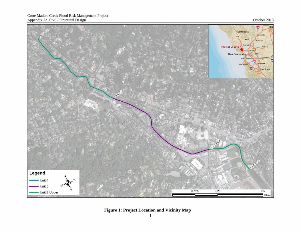
Figure 1: Project Location and Vicinity Map ................................................................................. 1
Figure 2: Features of the Selected Plan........................................................................................... 3
LIST OF ATTACHMENTS
Attachment 1: Concept Drawing Plates
Attachment 2: Proposed Access Route, Staging Area Locations and Construction Easement
Attachment 3: Preliminary Grading Plan, Profile and Cross-sections

Corte Madera Creek Flood Risk Management Project
Appendix I: Civil / Structural Engineering Report October 2018
2
LIST OF TABLES
Table 2-1. Material Quantity Estimates for the Selected Plan ........................................................ 5
Table 2-2. Potentially Impacted Utilities ........................................................................................ 7
Table 2-3. Construction Schedule ................................................................................................. 23
Table 2-4. Civil Engineering Design Requirements ....................................................................... 24
Table 3-1. Structural Engineering Design Requirements ............................................................... 27
Corte Madera Creek Flood Risk Management Project
Appendix A: Civil / Structural Design October 2018
Figure 1: Project Location and Vicinity Map
1

Corte Madera Creek Flood Risk Management Project
Appendix A: Civil / Structural Design
2018
October
1
PART 1 STUDY BACKGROUND
1.1 General
This appendix documents the Civil Design and Structural portion of the engineering analysis and
follows the format of Engineer Regulation1110-2-1150. It covers the recommend alternative
chosen to address the project objectives and solve the problems identified during the Alternative
Milestone. Figure 1 shows the general location and vicinity of Units 4, 3 and the upper portion
of Unit 2 that are included in the study.
1.2 Abbreviation and Names
TSP – Tentatively Selected Plan
USACE – US Army Corps of Engineers
NMFS – National Marine Fisheries Service
AMD – Adaptive Management Plan
CDFG – California Department of Fish and Games
CY – Cubic Yard
SF – Square Foot
QTY – Quantity
LS – Lump Sum
EA – Each
CE/ICA – Cost Effectiveness and Incremental Cost Analysis
1.3 Project-Specific References
USACE 2010. Final Corte Madera Creek Flood Control Study: Baseline Report. December.
USACE 1989. Corte Madera Creek Flood Control Project: Supplemental Information Paper II.
September.
USACE 1990. USGS Sediment Survey. February.
USACE 1980. Corte Madera Creek Flood Control Project Unit 4: Revised Final Design
Memorandum No. 2, Supplement No. 1. May.
1.4 Project Alternative Development and Selection
Including the no-action plan, ten alternatives were developed during the alternative formulation
process. The alternatives were screened down to a final five arrays of alternatives by using the
four main qualitative and quantitative screening criteria such as acceptability, completeness,
effectiveness, and efficiency. The five final arrays of alternatives selected based on the above
screening criteria include; Alternative A: Top-of-bank Floodwall, Alternative B: Top-of-bank
Floodwall/Setback Floodwall/College of Marin Widening, Alternative F: Bypass/Allen Park
Riparian Corridor/College of Marin Widening, Alternative G: Floodwall/ Allen Park Riparian
Corte Madera Creek Flood Risk Management Project
Appendix A: Civil / Structural Design
2018
October
2
Corridor, and Alternative J: Bypass/Allen Park Riparian Corridor/Floodwall. The five
alternatives were then compared based on mainly their complexity to address the project
objectives, providing solution to the problems identified during pan formulation, acceptability
for meeting local and USACE standards and policies, the efficiency to provide the highest
benefit and opportunities, and on the availability of land and easement to provided access for
construction. Each of these five alternatives were further evaluated to identify the most
qualified alternative by comparing their economic benefit/cost ratio. The Tentatively Selected
Plan (TSP) is the best fit alternative amongst the five final arrays of alternatives and is described
below.
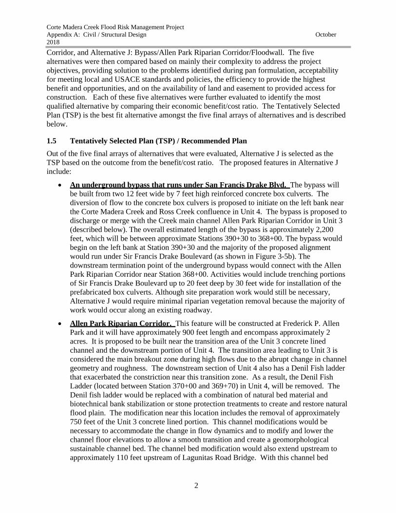
1.5 Tentatively Selected Plan (TSP) / Recommended Plan
Out of the five final arrays of alternatives that were evaluated, Alternative J is selected as the
TSP based on the outcome from the benefit/cost ratio. The proposed features in Alternative J
include:
An underground bypass that runs under San Francis Drake Blvd. The bypass will
be built from two 12 feet wide by 7 feet high reinforced concrete box culverts. The
diversion of flow to the concrete box culvers is proposed to initiate on the left bank near
the Corte Madera Creek and Ross Creek confluence in Unit 4. The bypass is proposed to
discharge or merge with the Creek main channel Allen Park Riparian Corridor in Unit 3
(described below). The overall estimated length of the bypass is approximately 2,200
feet, which will be between approximate Stations 390+30 to 368+00. The bypass would
begin on the left bank at Station 390+30 and the majority of the proposed alignment
would run under Sir Francis Drake Boulevard (as shown in Figure 3-5b). The
downstream termination point of the underground bypass would connect with the Allen
Park Riparian Corridor near Station 368+00. Activities would include trenching portions
of Sir Francis Drake Boulevard up to 20 feet deep by 30 feet wide for installation of the
prefabricated box culverts. Although site preparation work would still be necessary,
Alternative J would require minimal riparian vegetation removal because the majority of
work would occur along an existing roadway.
Allen Park Riparian Corridor. This feature will be constructed at Frederick P. Allen
Park and it will have approximately 900 feet length and encompass approximately 2
acres. It is proposed to be built near the transition area of the Unit 3 concrete lined
channel and the downstream portion of Unit 4. The transition area leading to Unit 3 is
considered the main breakout zone during high flows due to the abrupt change in channel
geometry and roughness. The downstream section of Unit 4 also has a Denil Fish ladder
that exacerbated the constriction near this transition zone. As a result, the Denil Fish
Ladder (located between Station 370+00 and 369+70) in Unit 4, will be removed. The
Denil fish ladder would be replaced with a combination of natural bed material and
biotechnical bank stabilization or stone protection treatments to create and restore natural
flood plain. The modification near this location includes the removal of approximately
750 feet of the Unit 3 concrete lined portion. This channel modifications would be
necessary to accommodate the change in flow dynamics and to modify and lower the
channel floor elevations to allow a smooth transition and create a geomorphological
sustainable channel bed. The channel bed modification would also extend upstream to
approximately 110 feet upstream of Lagunitas Road Bridge. With this channel bed

Corte Madera Creek Flood Risk Management Project
Appendix A: Civil / Structural Design
2018
October
3
modification, portion of the natural channel in Unit 4, extending a length of
approximately 115 feet, within the reach between Lagunitas Road Bridge and the fish
ladder, would be widened to increase hydraulic conveyance capacity. The demolished
section of the Unit 3 channel would be re-graded with native material and be designed to
meet fish passage criteria. Some additional proposed improvements that may be further
refined during the future design of the project include lowering of the southwest side of
the new creek channel in Allen Park to restore a historic floodplain and to increase flow
capacity. The Allen Park riparian corridor would include a widened, native substrate
channel that allows higher flows to spread over a larger area and include up to 4 feet
high floodwalls around its perimeter.
Before the flow from this proposed riparian corridor and restored Unit 3 reach enters the
downstream concrete lined section, additional bank armoring measures and new smooth
transitional features will be included to protect outflanking and guide/funnel the flow
towards the existing concrete channel. For the features included in the TSP plan, see
Figure 2 below.
Figure 2: Features of the Selected Plan
Floodwalls
Allen Park Perimeter Floodwall. Based on the result of the H&H model, a
maximum of 4 feet high perimeter floodwall is proposed around the Allen Park
riparian corridor. The floodwall would be constructed around the limits of the
floodplain resulting from the 25 year occurrence and provides assurance that flanking
Corte Madera Creek Flood Risk Management Project
Appendix A: Civil / Structural Design
2018
October
4
and bank erosion would not impact adjacent lands. It also serves the purpose of
funneling the flow towards the concrete lined section at its downstream end.
Granton Park neighborhood. Along the left bank of the Unit 3 and between
approximate Stations 344+00 and 355+00, and top-of-bank floodwall is proposed to be
near the Granton Park neighborhood terminating at the SMN Bridge on the western
boundary of the College of Marin campus. Based on the outcome from the H&H
model, the estimated height of the Granton Park floodwall would vary between 2 feet
at its upstream end and 6 feet downstream section. Due to the height of the wall,
extending the existing channel wall was not recommended. As a result, the new
floodwall would be installed as a separate wall adjacent and attached to the landward
face of the existing concrete channel wall.
College Avenue Floodwalls. Beginning approximately 75 feet from the upstream
face of the College Avenue bridge in Unit 3 and continuing all the way up until Station
325+70 in Unit 2, an overbank floodwall is proposed at the left bank of the creek. The
section of the Floodwall at the upstream face of the College Avenue Bridge (known as
a wingwall) would start or is tied to a high ground and be angled to smoothly funnel
flow towards the underside of the bridge. The wing wall begin at high ground. The
College Avenue floodwall would be constructed along the left bank and at its upstream
limit have a maximum height of 4 feet and gradually taper down to a height of 2 feet
downstream at its terminus.
PART 2 CIVIL DESIGN
2.1 Quantity Computation
2.1.1 Earthwork
The quantity computations were developed based on the preliminary concept designs. The large
amount of the excavations comes primarily from the features that include widened and deepened
the channel and floodwall construction. Based on the preliminary site condition evaluation as
well as existing geotechnical data, the recommended floodwall type for this project is inverted
“T”. As a result the amount of excavation is much larger compared to other floodwall types.
Compared to the overbank floodwalls, the off-set floodwalls are anticipated to be shallow in
depth and are anticipated to contribute lesser amount of excavation of materials.
The quantities have been reviewed for conformance with the plans and for the purpose of cost
estimating for the selected or recommended Alternative. For the selected alternative (TSP), the
table below summarizes the quantities of the different features to be utilized during the
restoration effort. Detailed Plans showing placement of the different features listed in the tables
below are provided in Attachments 4, 7 & 9. For construction cost associated with these
quantities, refer to the Cost Engineering Appendix.
2.1.2 Concrete
The quantities for the concrete is estimated based on preliminary conceptual alignment
developed during the alternative comparison. The wall heights were determined based on the
preliminary water surface elevation estimated through the H&H model during the with-project

Corte Madera Creek Flood Risk Management Project
Appendix A: Civil / Structural Design
2018
October
5
hydraulic analysis. Additional 2 feet assurance was included for all the floodwalls. The depth of
the concrete structures was estimated based on the preliminary analysis of the underlying soil
condition, the height of the proposed floodwalls, and availability real estate for the size of the
footing. Most of the top-of-bank floodwall structures for the selected alternative are anticipated
not to be as deep as the existing channel wall bed. Further future refinement and
recommendation based on the Geotechnical and Structural factors is necessary to determine the
sufficiency of the depths as well as the integrity of the existing concrete structures.
2.1.1 Shoring Material
Estimates were based on unit area of the shoring material. Usage of the shoring material is
optional dependent on the depth and slope of the excavation. Shoring will be used to ensure
safety of workers from unstable soil. Soil type and condition at the project site plays important
factor in determining the amount of shoring needed when the depth of excavation is above the
maximum limit provided by OSHA for stable soil.
2.1.2 Formwork
Estimates were based on unit area of the formwork. Steel formwork and accessories will be
utilized for erecting of the floodwalls.
2.1.3 Rocks and Boulders
To be included during the next design refinement.
2.1.4 Biotechnical Bank Stabilization and Erosion Protection Fabrics
To be included during the next design refinement.
2.1.5 Tree Replanting
To be included during the next design refinement. Tree removal is included in the analysis.
2.1.6 Bank Stabilization Measures
To be included during the next design refinement.
Table 2-1. Material Quantity Estimates for the Selected Plan
Task Quantity Unit
Underground Reinforced Concrete Bypass
Concrete Inlet Weir 10 CY
Concrete Inlet Headwall 18 CY
Traffic Re-route and Control 500,000 LS
Road Asphalt Demolition 7,333 SY
Shoring 99,000 SF
Excavation 36,667 CY
Double 12'X7' Underground Concrete Bypass 3,259 CY
Backfill 12,222 CY
Road Asphalt Pavement and Markings 66,000 SF

Corte Madera Creek Flood Risk Management Project
Appendix A: Civil / Structural Design
2018
October
6
Concrete Outlet Headwall 18 CY
Reinforced Concrete Floodwalls
Clearing & Grubbing 1.37 AC
Tree Removal 1.37 AC
Excavation 5,669 CY
Shoring 12,000 SF
Cast-in-place Concrete 2,493 CY
Form Work 44,445 SF
Backfill 3,067 CY
Hydro Seed 1.1 AC
Allen Park Riparian Corridor
Clearing & Grubbing 1.7 AC
Tree Removal 1.7 AC
Demolish Pavement 3,319 SY
Demolish Concrete Channel 1,806 CY
Excavation(Area 1) 19,828 CY
Excavation (Area 2&3) 5,311 CY
Erosion Control Blanket 5,167 SY
Hydro Seed 1.7 AC
Fish Passage Transition Grading 270 CY
Fish Ladder
Concrete/Gabion Demolition 49 CY
Excavation 114 CY
Erosion Mats (Jute Mesh) 110 SY
Hydro Seed 0.02 AC AC = Acre, SY = Square Yard, CY = Cubic Yard, SF = Square Foot
2.2 Relocations
A sewer pipe that requires relocation was identified within the limits of the project. The sewer
line crosses the creek at approximate Station of 370+00 with two 24 inch Techite pipes near the
transition area of Unit 3 and 4. This location is where construction of the concrete channel was
halted in 1971. For the recommended plan, this location would have a number of activities
during construction including; removal of denil fish ladder, channel bed excavation, removal of
portion of the Unit 3 concrete channel and construction of the Allen Park Riparian Corridor and
floodwalls. Within the limits of the proposed Allen Park riparian corridor, approximately 1,000 ft
segment of the sanitary sewer is proposed to be relocated to the right along and parallel with the
right side perimeter floodwall. The crossing at Station 370+00 will either be completely
removed or capped and abandoned in-place. The proposed relocation would require to new
crossings that will connect to the sewer line running along the left bank of the creek. Further
coordination with the Sponsor and Ross Valley Sanitary District (RVSD) regarding the
relocation of this sewer line will be made during the feasibility phase preliminary design. It is
the responsibility of the project Sponsor to coordinate with the RVSD in preparing the
preliminary relocation designs. It is also the responsibility of the Sponsor to further investigate if

Corte Madera Creek Flood Risk Management Project
Appendix A: Civil / Structural Design
2018
October
7
any additional relations are needed or identified during the future design phase of the project by
communicating and coordinating with all the utility agencies impacted by the proposed project
features. The pipe should be relocated to the proposed location before construction of the project
near this site begins.
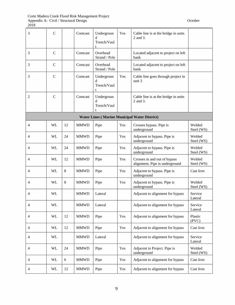
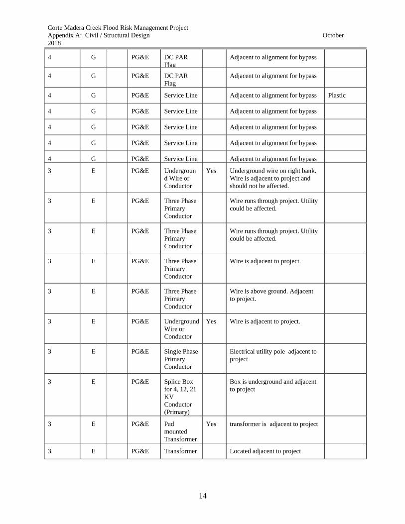
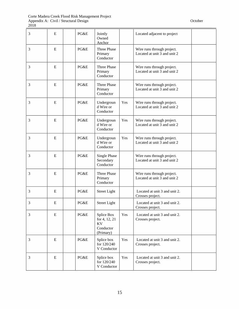
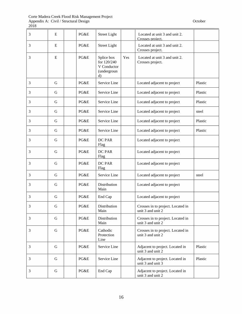
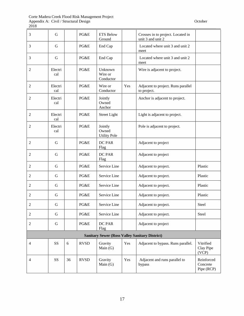
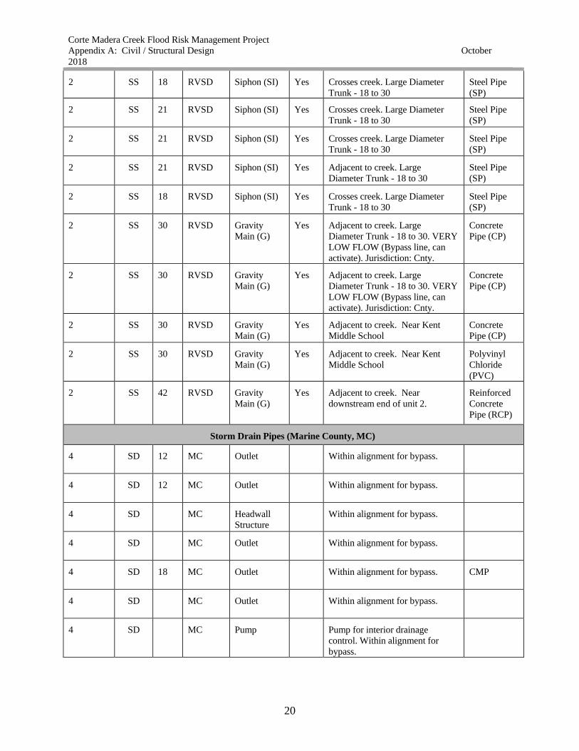
2.3 Utilities
All utilities in the vicinity of the study area have been shown on the preliminary drawings
(Attachment 5). All the locations shown on the plans are approximate and will be confirmed
during future detail design stages and before construction. The various types of utilities that may
potentially be impacted include; overhead and underground electrical lines, gas lines,
communication cables and wires, sanitary sewer lines, water lines and storm drains lines as
shown in Table 2-2 below. It is anticipated that only few of the overhead power lines will
impacted by the construction activity of the selected alternative. A number of storm drain utility
pipes have been identified within the project footprints that may be impacted temporarily. If any
additional utilities are discovered during the next phases of the project, they will be included on
the next preliminary design stages. For list of the utilities within the vicinity of the project that
may potentially be impacted, see Attachment 5 and Table 2-2 below.
Table 2-2. Potentially Impacted Utilities.
Channel
(Unit #)
Utility
Type
Pipe
Size
Owner Feature
Type
Burie
d
Description Material
type
Communication (AT&T and Comcast)
4 T/C
AT&T Undergroun
d Cable
Crosses bypass.
4 T/C
AT&T Conduit
Crosses bypass.
4 T/C
AT&T Conduit
Adjacent to alignment for bypass
4 T/C
AT&T Conduit
Adjacent to Bypass. Runs parallel
to Creek on left bank
4 T/C
AT&T Conduit
Adjacent to Bypass. Runs parallel
to Creek on left bank
4 T/C
AT&T Aerial Cable
Adjacent to Bypass. Runs parallel
to Creek on left bank
4 T/C
AT&T Aerial Cable
Adjacent to Bypass. Runs parallel
to Creek on left bank
3 T/C
AT&T Cable Yes Adjacent to project. Located at
upstream bridge of unit 2,
downstream bridge unit 3
3 T/C
AT&T Undergroun
d Cable
Yes Crosses project. Located at
upstream bridge of unit 2,
downstream bridge unit 3
3 T/C
AT&T Undergroun
d Cable
Yes Adjacent to project. Located at
upstream bridge of unit 2,
downstream bridge unit 3

Corte Madera Creek Flood Risk Management Project
Appendix A: Civil / Structural Design
2018
October
8
3 T/C
AT&T Undergroun
d Cable
Yes Adjacent to project. Located at
upstream bridge of unit 2,
downstream bridge unit 3
3 T/C
AT&T Undergroun
d Cable
Yes Crosses project. Located at
upstream bridge of unit 2,
downstream bridge unit 3
3 T/C
AT&T Undergroun
d Cable
Yes Adjacent to project. Located at
upstream bridge of unit 2,
downstream bridge unit 3
3 T/C
AT&T Conduit
Adjacent to project.
3 T/C
AT&T Undergroun
d Cable
Yes Adjacent to project.
3 T/C
AT&T Undergroun
d Cable
Yes Adjacent to project.
3 T/C
AT&T Conduit
Adjacent to project.
3 T/C
AT&T Undergroun
d Cable
Yes Adjacent to project.
3 T/C
AT&T Undergroun
d Cable
Yes Crosses project.
3 T/C
AT&T Undergroun
d Cable
Yes Crosses project.
3 T/C
AT&T Conduit
Crosses project.
3 T/C
AT&T Undergroun
d Cable
Yes Crosses project and runs parallel
on right bank
3 T/C
AT&T Undergroun
d Cable
Yes Crosses project and runs parallel
on right bank
2 T/C
AT&T
Crosses project
2 T/C
AT&T Building
Cable
Yes Adjacent to project
2 T/C
AT&T Undergroun
d Cable
Yes Adjacent to project. Runs parallel
to project alignment ending at
upstream end of unit 2.
4 C
Comcast Overhead
Strand / Pole
Cable is within alignment for
bypass
4 C
Comcast Overhead
Strand / Pole
Cable line at upstream end of unit
4. It is adjacent to and crosses the
alignment for bypass
4 C
Comcast Overhead
Strand / Pole
Cable line runs adjacent to bypass
alignment
Corte Madera Creek Flood Risk Management Project
Appendix A: Civil / Structural Design
2018
October
9
3 C
Comcast Undergroun
d
Trench/Vaul
t
Yes Cable line is at the bridge in units
2 and 3.
3 C
Comcast Overhead
Strand / Pole
Located adjacent to project on left
bank
3 C
Comcast Overhead
Strand / Pole
Located adjacent to project on left
bank
3 C
Comcast Undergroun
d
Trench/Vaul
t
Yes Cable line goes through project in
unit 3
2 C
Comcast Undergroun
d
Trench/Vaul
t
Cable line is at the bridge in units
2 and 3.
Water Lines ( Marine Municipal Water District)
4 WL 12 MMWD Pipe Yes Crosses bypass. Pipe is
underground
Welded
Steel (WS)
4 WL 24 MMWD Pipe Yes Adjacent to bypass. Pipe is
underground
Welded
Steel (WS)
4 WL 24 MMWD Pipe Yes Adjacent to bypass. Pipe is
underground
Welded
Steel (WS)
4 WL 12 MMWD Pipe Yes Crosses in and out of bypass
alignment. Pipe is underground
Welded
Steel (WS)
4 WL 8 MMWD Pipe Yes Adjacent to bypass. Pipe is
underground
Cast Iron
4 WL 8 MMWD Pipe Yes Adjacent to bypass. Pipe is
underground
Welded
Steel (WS)
4 WL
MMWD Lateral
Adjacent to alignment for bypass Service
Lateral
4 WL
MMWD Lateral
Adjacent to alignment for bypass Service
Lateral
4 WL 12 MMWD Pipe Yes Adjacent to alignment for bypass Plastic
(PVC)
4 WL 12 MMWD Pipe Yes Adjacent to alignment for bypass Cast Iron
4 WL
MMWD Lateral
Adjacent to alignment for bypass Service
Lateral
4 WL 24 MMWD Pipe Yes Adjacent to Project. Pipe is
underground
Welded
Steel (WS)
4 WL 6 MMWD Pipe Yes Adjacent to alignment for bypass Cast Iron
4 WL 12 MMWD Pipe Yes Adjacent to alignment for bypass Cast Iron

Corte Madera Creek Flood Risk Management Project
Appendix A: Civil / Structural Design
2018
October
10
4 WL 6 MMWD Pipe Yes Adjacent to alignment for bypass Cast Iron
4 WL 12 MMWD Pipe Yes Adjacent to alignment for bypass Cast Iron
4 WL 12 MMWD Pipe Yes Adjacent to alignment for bypass Cast Iron
4 WL 12 MMWD Pipe Yes Adjacent to alignment for bypass Cast Iron
3 WL 10 MMWD Pipe
Crosses at College Ave. Pipe is
above ground
Welded
Steel (WS)
3 WL 10 MMWD Pipe
Crosses at College Ave. Pipe is
underground
Welded
Steel (WS)
3 WL 12 MMWD Pipe
Parallels on bike path and
adjacent to project. Pipe is
underground
Welded
Steel (WS)
3 WL 24 MMWD Pipe
Parallels on bike path and
adjacent to project. Pipe is
underground
Welded
Steel (WS)
3 WL 24 MMWD Pipe
Parallels on bike path and
adjacent to project. Pipe is
underground
Welded
Steel (WS)
3 WL
MMWD Lateral
Adjacent to Project and parallel to
bike path
Service
Lateral
3 WL 1 MMWD Pipe
Adjacent to Project and parallel to
bike path
Copper
3 WL 24 MMWD Pipe Yes Adjacent to Project and parallel to
bike path.
Welded
Steel (WS)
3 WL 24 MMWD Pipe Yes Adjacent to Project and parallel to
bike path.
Welded
Steel (WS)
3 WL 24 MMWD Pipe Yes Adjacent to Project and parallel to
bike path.
Welded
Steel (WS)
3 WL 12 MMWD Pipe Yes Adjacent to Project and parallel to
bike path.
Welded
Steel (WS)
3 WL 12 MMWD Pipe Yes Adjacent to Project and parallel to
bike path.
Welded
Steel (WS)
3 WL 24 MMWD Pipe Yes Adjacent to Project and parallel to
bike path.
Welded
Steel (WS)
3 WL 26 MMWD Pipe Yes Adjacent to Project and parallel to
bike path.
Welded
Steel (WS)
3 WL 26 MMWD Pipe Yes Adjacent to Project and parallel to
bike path.
Welded
Steel (WS)
3 WL 8 MMWD Pipe Yes Adjacent to Project and parallel to
bike path.
Welded
Steel (WS)
3 WL
MMWD Lateral
Adjacent to Project and parallel to
bike path.
Service
Lateral

Corte Madera Creek Flood Risk Management Project
Appendix A: Civil / Structural Design
2018
October
11
3 WL 24 MMWD Pipe
Adjacent to Project. Pipe is
underground
Welded
Steel (WS)
3 WL 12 MMWD Pipe
Adjacent to Project. Pipe is
underground
Welded
Steel (WS)
3 WL
MMWD Lateral
Adjacent to Project. Service
Lateral
3 WL 24 MMWD Pipe
Adjacent to Project. Pipe is
underground
Welded
Steel (WS)
2 WL 20 MMWD Pipe
Crosses at Stadium Way, above
ground
Welded
Steel (WS)
2 WL 20 MMWD Pipe
Crosses at Stadium Way,
underground
Welded
Steel (WS)
2 WL
MMWD Lateral
Adjacent to Stadium Way Service
Lateral
2 WL
MMWD Lateral
Adjacent to Stadium Way Service
Lateral
2 WL 8 MMWD Pipe
Crosses at Stadium Way,
underground
Welded
Steel (WS)
2 WL 9 MMWD Pipe
Crosses at Stadium Way,
underground
Welded
Steel (WS)
2 WL 10 MMWD Pipe
Crosses at College Ave. Pipe is
above ground
Welded
Steel (WS)
2 W 10 MMWD Pipe
Crosses at College Ave. Pipe is
underground
Welded
Steel (WS)
Electrical Lines (PG&E)
4 E
PG&E Single Phase
Secondary
Conductor
Utility is within alignment for
bypass
4 E
PG&E Three Phase
Secondary
Conductor
Utility is within the project limits.
4 E
PG&E Three Phase
Secondary
Conductor
Utility is within alignment for
bypass
4 E
PG&E Single Phase
Secondary
Conductor
Utility is within alignment for
bypass
4 E
PG&E Three Phase
Secondary
Conductor
Utility is within alignment for
bypass

Corte Madera Creek Flood Risk Management Project
Appendix A: Civil / Structural Design
2018
October
12
4 E
PG&E Underground
Wire or
Conductor
Underground wire within
alignment for bypass
4 E
PG&E Jointly
Owned
Utility Pole
Located adjacent to bypass
4 E
PG&E Jointly
Owned
Utility Pole
Located adjacent to bypass
4 E
PG&E Street Light
Located adjacent to bypass
4 E
PG&E Transformer
Bank Open
Delta
Located within alignment for
bypass
4 E
PG&E Street Light
Located near bypass alignment
4 E
PG&E Line Fuse
Located adjacent to bypass
4 E
PG&E Line Switch
Located within alignment for
bypass
4 E
PG&E Jointly
Owned
Utility Pole
Located within alignment for
bypass
4 G
PG&E Service Line
Adjacent to bypass Plastic
4 G
PG&E Service Line
Adjacent to bypass Plastic
4 G
PG&E Service Line
Adjacent to bypass Plastic
4 G
PG&E Service Line
Adjacent to bypass Plastic
4 G
PG&E Service Line
Located within alignment for
bypass
Plastic
4 G
PG&E DC PAR
Flag
Adjacent to bypass alignment
4 G
PG&E DC PAR
Flag
Located within alignment for
bypass
4 G
PG&E Service Line
Adjacent to alignment for bypass Plastic
4 G
PG&E Service Line
Located within alignment for
bypass
Steel
4 G
PG&E Service Line
Adjacent to alignment for bypass Steel
4 G
PG&E DC PAR
Flag
Adjacent to alignment for bypass
4 G
PG&E DC PAR
Flag
Located within alignment for
bypass

Corte Madera Creek Flood Risk Management Project
Appendix A: Civil / Structural Design
2018
October
13
4 G
PG&E DC PAR
Flag
Located within alignment for
bypass
4 G
PG&E DC PAR
Flag
Located within alignment for
bypass
4 G
PG&E Service Line
Located within alignment for
bypass
Steel
4 G
PG&E Service Line
Located within alignment for
bypass
Steel
4 G
PG&E Service Line
Adjacent to alignment for bypass Plastic
4 G
PG&E Service Line
Adjacent to alignment for bypass Plastic
4 G
PG&E Service Line
Adjacent to alignment for bypass Plastic
4 G
PG&E DC PAR
Flag
Located within alignment for
bypass
4 G
PG&E DC PAR
Flag
Located within alignment for
bypass
4 G
PG&E DC PAR
Flag
Located within alignment for
bypass
4 G
PG&E Service Line
Located within alignment for
bypass
Plastic
4 G
PG&E Distribution
Main
Adjacent to alignment for bypass Plastic
4 G
PG&E Distribution
Main
Located within alignment for
bypass
Plastic
4 G
PG&E Deactivated
Pipe
Located within alignment for
bypass
4 G
PG&E Cathodic
Protection
Line
Located within alignment for
bypass
4 G
PG&E Cathodic
Protection
Line
Located within alignment for
bypass
4 G
PG&E Service Line
Adjacent to alignment for bypass Plastic
4 G
PG&E Service Line
Located adjacent to bypass
alignment
Plastic
4 G
PG&E ETS Below
Ground
Adjacent to alignment for bypass
4 G
PG&E ETS Below
Ground
Located within alignment for
bypass
4 G
PG&E DC PAR
Flag
Located within alignment for
bypass
Corte Madera Creek Flood Risk Management Project
Appendix A: Civil / Structural Design
2018
October
14
4 G
PG&E DC PAR
Flag
Adjacent to alignment for bypass
4 G
PG&E DC PAR
Flag
Adjacent to alignment for bypass
4 G
PG&E Service Line
Adjacent to alignment for bypass Plastic
4 G
PG&E Service Line
Adjacent to alignment for bypass
4 G
PG&E Service Line
Adjacent to alignment for bypass
4 G
PG&E Service Line
Adjacent to alignment for bypass
4 G
PG&E Service Line
Adjacent to alignment for bypass
3 E
PG&E Undergroun
d Wire or
Conductor
Yes Underground wire on right bank.
Wire is adjacent to project and
should not be affected.
3 E
PG&E Three Phase
Primary
Conductor
Wire runs through project. Utility
could be affected.
3 E
PG&E Three Phase
Primary
Conductor
Wire runs through project. Utility
could be affected.
3 E
PG&E Three Phase
Primary
Conductor
Wire is adjacent to project.
3 E
PG&E Three Phase
Primary
Conductor
Wire is above ground. Adjacent
to project.
3 E
PG&E Underground
Wire or
Conductor
Yes Wire is adjacent to project.
3 E
PG&E Single Phase
Primary
Conductor
Electrical utility pole adjacent to
project
3 E
PG&E Splice Box
for 4, 12, 21
KV
Conductor
(Primary)
Box is underground and adjacent
to project
3 E
PG&E Pad
mounted
Transformer
Yes transformer is adjacent to project
3 E
PG&E Transformer
Located adjacent to project
Corte Madera Creek Flood Risk Management Project
Appendix A: Civil / Structural Design
2018
October
15
3 E
PG&E Jointly
Owned
Anchor
Located adjacent to project
3 E
PG&E Three Phase
Primary
Conductor
Wire runs through project.
Located at unit 3 and unit 2
3 E
PG&E Three Phase
Primary
Conductor
Wire runs through project.
Located at unit 3 and unit 2
3 E
PG&E Three Phase
Primary
Conductor
Wire runs through project.
Located at unit 3 and unit 2
3 E
PG&E Undergroun
d Wire or
Conductor
Yes Wire runs through project.
Located at unit 3 and unit 2
3 E
PG&E Undergroun
d Wire or
Conductor
Yes Wire runs through project.
Located at unit 3 and unit 2
3 E
PG&E Undergroun
d Wire or
Conductor
Yes Wire runs through project.
Located at unit 3 and unit 2
3 E
PG&E Single Phase
Secondary
Conductor
Wire runs through project.
Located at unit 3 and unit 2
3 E
PG&E Three Phase
Primary
Conductor
Wire runs through project.
Located at unit 3 and unit 2
3 E
PG&E Street Light
Located at unit 3 and unit 2.
Crosses project.
3 E
PG&E Street Light
Located at unit 3 and unit 2.
Crosses project.
3 E
PG&E Splice Box
for 4, 12, 21
KV
Conductor
(Primary)
Yes Located at unit 3 and unit 2.
Crosses project.
3 E
PG&E Splice box
for 120/240
V Conductor
Yes Located at unit 3 and unit 2.
Crosses project.
3 E
PG&E Splice box
for 120/240
V Conductor
Yes Located at unit 3 and unit 2.
Crosses project.
Corte Madera Creek Flood Risk Management Project
Appendix A: Civil / Structural Design
2018
October
16
3 E
PG&E Street Light
Located at unit 3 and unit 2.
Crosses project.
3 E
PG&E Street Light
Located at unit 3 and unit 2.
Crosses project.
3 E
PG&E Splice box
for 120/240
V Conductor
(undergroun
d)
Yes Located at unit 3 and unit 2.
Crosses project.
3 G
PG&E Service Line
Located adjacent to project Plastic
3 G
PG&E Service Line
Located adjacent to project Plastic
3 G
PG&E Service Line
Located adjacent to project Plastic
3 G
PG&E Service Line
Located adjacent to project steel
3 G
PG&E Service Line
Located adjacent to project Plastic
3 G
PG&E Service Line
Located adjacent to project Plastic
3 G
PG&E DC PAR
Flag
Located adjacent to project
3 G
PG&E DC PAR
Flag
Located adjacent to project
3 G
PG&E DC PAR
Flag
Located adjacent to project
3 G
PG&E Service Line
Located adjacent to project steel
3 G
PG&E Distribution
Main
Located adjacent to project
3 G
PG&E End Cap
Located adjacent to project
3 G
PG&E Distribution
Main
Crosses in to project. Located in
unit 3 and unit 2
3 G
PG&E Distribution
Main
Crosses in to project. Located in
unit 3 and unit 2
3 G
PG&E Cathodic
Protection
Line
Crosses in to project. Located in
unit 3 and unit 2
3 G
PG&E Service Line
Adjacent to project. Located in
unit 3 and unit 2
Plastic
3 G
PG&E Service Line
Adjacent to project. Located in
unit 3 and unit 3
Plastic
3 G
PG&E End Cap
Adjacent to project. Located in
unit 3 and unit 2
Corte Madera Creek Flood Risk Management Project
Appendix A: Civil / Structural Design
2018
October
17
3 G
PG&E ETS Below
Ground
Crosses in to project. Located in
unit 3 and unit 2
3 G
PG&E End Cap
Located where unit 3 and unit 2
meet
3 G
PG&E End Cap
Located where unit 3 and unit 2
meet
2 Electri
cal
PG&E Unknown
Wire or
Conductor
Wire is adjacent to project.
2 Electri
cal
PG&E Wire or
Conductor
Yes Adjacent to project. Runs parallel
to project.
2 Electri
cal
PG&E Jointly
Owned
Anchor
Anchor is adjacent to project.
2 Electri
cal
PG&E Street Light
Light is adjacent to project.
2 Electri
cal
PG&E Jointly
Owned
Utility Pole
Pole is adjacent to project.
2 G
PG&E DC PAR
Flag
Adjacent to project
2 G
PG&E DC PAR
Flag
Adjacent to project
2 G
PG&E Service Line
Adjacent to project. Plastic
2 G
PG&E Service Line
Adjacent to project. Plastic
2 G
PG&E Service Line
Adjacent to project. Plastic
2 G
PG&E Service Line
Adjacent to project. Plastic
2 G
PG&E Service Line
Adjacent to project. Steel
2 G
PG&E Service Line
Adjacent to project. Steel
2 G
PG&E DC PAR
Flag
Adjacent to project
Sanitary Sewer (Ross Valley Sanitary District)
4 SS 6 RVSD Gravity
Main (G)
Yes Adjacent to bypass. Runs parallel. Vitrified
Clay Pipe
(VCP)
4 SS 36 RVSD Gravity
Main (G)
Yes Adjacent and runs parallel to
bypass
Reinforced
Concrete
Pipe (RCP)

Corte Madera Creek Flood Risk Management Project
Appendix A: Civil / Structural Design
2018
October
18
4 SS 6 RVSD Gravity
Main (G)
Yes Adjacent to bypass. Runs parallel. Asbestos
Cement
(AC)
4 SS 36 RVSD Gravity
Main (G)
Yes Adjacent to bypass. Connects to
two lines that cross the bypass,
SSL-01 and SSL-15
Reinforced
Concrete
Pipe (RCP)
4 SS 39 RVSD Gravity
Main (G)
Yes Located at unit 4 downstream and
unit 3 upstream. Connects to two
lines that cross the bypass, SSL-
01 and SSL-15. Runs parallel in
unit 3
Reinforced
Concrete
Pipe (RCP)
4 SS 24 RVSD Siphon (SI) Yes Located at unit 4 downstream and
unit 3 upstream. Crosses bypass
Techite
(TEC)
4 SS 25 RVSD Siphon (SI) Yes Located at unit 4 downstream and
unit 3 upstream. Crosses bypass
Techite
(TEC)
3 SS 12 RVSD Gravity
Main (G)
Yes Located adjacent to project.
Connected to SSL-09.
Reinforced
Concrete
Pipe (RCP)
3 SS 39 RVSD Gravity
Main (G)
Yes Adjacent and runs parallel to
project in unit 3 right bank. Ross
Valley Trunk Sewer - Corte
Madera Creek
Reinforced
Concrete
Pipe (RCP)
3 SS 39 RVSD Gravity
Main (G)
Yes Adjacent and runs parallel to
project in unit 3 right bank. Ross
Valley Trunk Sewer - Corte
Madera Creek
Reinforced
Concrete
Pipe (RCP)
3 SS 39 RVSD Gravity
Main (G)
Yes Adjacent and runs parallel to
project in unit 3 right bank. Ross
Valley Trunk Sewer - Corte
Madera Creek
Reinforced
Concrete
Pipe (RCP)
3 SS 39 RVSD Gravity
Main (G)
Yes Adjacent and runs parallel to
project in unit 3 right bank. Ross
Valley Trunk Sewer - Corte
Madera Creek
Reinforced
Concrete
Pipe (RCP)
3 SS 39 RVSD Gravity
Main (G)
Yes Adjacent and runs parallel to
project in unit 3 right bank. Ross
Valley Trunk Sewer - Corte
Madera Creek
Reinforced
Concrete
Pipe (RCP)
3 SS 39 RVSD Gravity
Main (G)
Yes Adjacent and runs parallel to
project in unit 3 right bank. Ross
Valley Trunk Sewer - Corte
Madera Creek
Reinforced
Concrete
Pipe (RCP)
3 SS 39 RVSD Gravity
Main (G)
Yes Adjacent and runs parallel to
project in unit 3 right bank. Ross
Valley Trunk Sewer - Corte
Madera Creek
Reinforced
Concrete
Pipe (RCP)
Corte Madera Creek Flood Risk Management Project
Appendix A: Civil / Structural Design
2018
October
19
3 SS 12 RVSD Gravity
Main (G)
Yes Located adjacent to project.
Connects to SSL-60 and SSL-37
Reinforced
Concrete
Pipe (RCP)
3 SS 39 RVSD Gravity
Main (G)
Yes Adjacent and runs parallel to
project in unit 3 right bank. Ross
Valley Trunk Sewer - Corte
Madera Creek
Reinforced
Concrete
Pipe (RCP)
3 SS 39 RVSD Gravity
Main (G)
Yes Adjacent and runs parallel to
project in unit 3 right bank ends
in unit 2. Ross Valley Trunk
Sewer - Corte Madera Creek
Reinforced
Concrete
Pipe (RCP)
2 SS 39 RVSD Gravity
Main (G)
Yes Adjacent and runs parallel to
project in unit 3 right bank ends
in unit 2. Ross Valley Trunk
Sewer - Corte Madera Creek
Reinforced
Concrete
Pipe (RCP)
2 SS 39 RVSD Gravity
Main (G)
Yes Adjacent and runs parallel in unit
2. Ross Valley Trunk Sewer -
Corte Madera Creek
Reinforced
Concrete
Pipe (RCP)
2 SS 39 RVSD Gravity
Main (G)
Yes Adjacent and runs parallel in unit
2. Ross Valley Trunk Sewer -
Corte Madera Creek
Reinforced
Concrete
Pipe (RCP)
2 SS 39 RVSD Gravity
Main (G)
Yes Adjacent and runs parallel in unit
2. Ross Valley Trunk Sewer -
Corte Madera Creek
Reinforced
Concrete
Pipe (RCP)
2 SS 8 RVSD Gravity
Main (G)
Yes Adjacent to project in unit 2.
Located at 890 College Ave
Easement. Runs perpendicular to
creek connecting SSL-02 and
SSL-63
Asbestos
Cement
(AC)
2 SS 8 RVSD Gravity
Main (G)
Yes Adjacent to project in unit 2.
Located at 890 College Ave
Easement. Runs parallel to creek
2 SS 8 RVSD Gravity
Main (G)
Yes Adjacent to project in unit 2.
Located at 890 College Ave
Easement. Runs parallel to creek
2 SS 42 RVSD Gravity
Main (G)
Yes Adjacent and runs parallel in unit
2. Ross Valley Trunk Sewer -
Corte Madera Creek
Reinforced
Concrete
Pipe (RCP)
2 SS 30 RVSD Gravity
Main (G)
Yes Adjacent to project in unit 2.
Stadium Way Siphon connected
to SSL-45
Steel Pipe
(SP)
2 SS 18 RVSD Siphon (SI) Yes Crosses creek. Large Diameter
Trunk - 18 to 30
Steel Pipe
(SP)
Corte Madera Creek Flood Risk Management Project
Appendix A: Civil / Structural Design
2018
October
20
2 SS 18 RVSD Siphon (SI) Yes Crosses creek. Large Diameter
Trunk - 18 to 30
Steel Pipe
(SP)
2 SS 21 RVSD Siphon (SI) Yes Crosses creek. Large Diameter
Trunk - 18 to 30
Steel Pipe
(SP)
2 SS 21 RVSD Siphon (SI) Yes Crosses creek. Large Diameter
Trunk - 18 to 30
Steel Pipe
(SP)
2 SS 21 RVSD Siphon (SI) Yes Adjacent to creek. Large
Diameter Trunk - 18 to 30
Steel Pipe
(SP)
2 SS 18 RVSD Siphon (SI) Yes Crosses creek. Large Diameter
Trunk - 18 to 30
Steel Pipe
(SP)
2 SS 30 RVSD Gravity
Main (G)
Yes Adjacent to creek. Large
Diameter Trunk - 18 to 30. VERY
LOW FLOW (Bypass line, can
activate). Jurisdiction: Cnty.
Concrete
Pipe (CP)
2 SS 30 RVSD Gravity
Main (G)
Yes Adjacent to creek. Large
Diameter Trunk - 18 to 30. VERY
LOW FLOW (Bypass line, can
activate). Jurisdiction: Cnty.
Concrete
Pipe (CP)
2 SS 30 RVSD Gravity
Main (G)
Yes Adjacent to creek. Near Kent
Middle School
Concrete
Pipe (CP)
2 SS 30 RVSD Gravity
Main (G)
Yes Adjacent to creek. Near Kent
Middle School
Polyvinyl
Chloride
(PVC)
2 SS 42 RVSD Gravity
Main (G)
Yes Adjacent to creek. Near
downstream end of unit 2.
Reinforced
Concrete
Pipe (RCP)
Storm Drain Pipes (Marine County, MC)
4 SD 12 MC Outlet
Within alignment for bypass.
4 SD 12 MC Outlet
Within alignment for bypass.
4 SD
MC Headwall
Structure
Within alignment for bypass.
4 SD
MC Outlet
Within alignment for bypass.
4 SD 18 MC Outlet
Within alignment for bypass. CMP
4 SD
MC Outlet
Within alignment for bypass.
4 SD
MC Pump
Pump for interior drainage
control. Within alignment for
bypass.

Corte Madera Creek Flood Risk Management Project
Appendix A: Civil / Structural Design
2018
October
21
4 SD
MC Pump
Pump for interior drainage
control. Within alignment for
bypass.
4 SD
MC Outlet
Within alignment for bypass.
4 SD
MC Outlet
Within alignment for bypass.
4 SD
MC Outlet
Within alignment for bypass.
4 SD
MC Outlet
Within alignment for bypass.
4 SD
MC Pump
Pump for interior drainage
control. Within alignment for
bypass.
4 SD
MC Outlet
Within alignment for bypass.
4 SD
MC Outlet
Within alignment for bypass.
4 SD
MC Outlet
Within alignment for bypass.
4 SD
MC Outlet
Within alignment for bypass.
4 SD
MC ?
Within alignment for bypass.
4 SD
MC Headwall
Structure
Within alignment for bypass.
4 SD
MC Headwall
Structure
Within alignment for bypass.
4 SD
MC Outlet
Within alignment for bypass.
4 SD
MC Outlet
Within alignment for bypass.
4 SD
MC Inlet
Within alignment for bypass.
4 SD
MC Outlet
3 SD
MC outlet
Drains into Creek
3 SD
MC outlet
Drains into Creek
3 SD
MC outlet
Drains into Creek
3 SD
MC outlet
Drains into Creek
3 SD 72 MC outlet
Drains into Creek RCP

Corte Madera Creek Flood Risk Management Project
Appendix A: Civil / Structural Design
2018
October
22
3 SD 36 MC outlet
Drains into Creek RCP
3 SD 18 MC outlet
Drains into Creek RCP
3 SD
MC Catch Basin
3 SD 12 MC outlet
Drains into Creek CMP
3 SD 8 MC outlet
Drains into Creek
3 SD 12 MC outlet
Drains into Creek
3 SD 60 MC outlet
Drains into Creek
3 SD 18 MC outlet
Drains into Creek RCP
3 SD 18 MC Catch Basin
Near Creek could be effected.
3 SD 18 MC outlet
Drains into Creek RCP
3 SD 30 MC outlet
Drains into Creek RCP
3 SD 24 MC outlet
Drains into Creek RCP
3 SD 30 MC outlet
Drains into Creek RCP
3 SD 24 MC outlet
Drains into Creek RCP
3 SD 18 MC outlet
Drains into Creek RCP
3 SD 24 MC outlet
Drains into Creek RCP
3 SD 18 MC outlet
Drains into Creek CMP
3 SD 24 MC outlet
flap gate drains into Creek RCP
3 SD 24 MC outlet
Drains into Creek RCP
3 SD 8 MC outlet
Drains into Creek
3 SD 24 MC outlet
Drains into Creek RCP
3 SD 18 MC outlet
Drains into Creek RCP
3 SD 24 MC outlet
Drains into Creek RCP
2 SD
MC Outlet
Drains into Creek. not sure if two
pipes
2 SD
MC Outlet
Drains into Creek. not sure if two
pipes
2 SD 15 MC Outlet
Drains into Creek CMP

Corte Madera Creek Flood Risk Management Project
Appendix A: Civil / Structural Design
2018
October
23
2 SD 24 MC Outlet
Drains into Creek CMP
2 SD 15 MC Outlet
Drains into Creek CMP
2 SD 15 MC Outlet
Drains into Creek CMP
2 SD
MC Outlet
Drains into Creek
2 SD
MC Outlet
Drains into Creek
2 SD
MC Outlet
Drains into Creek
2 SD
MC Outlet
Drains into Creek
2 SD 24 MC Outlet
Drains into Creek CMP
2 SD
MC Outlet
Drains into Creek RCP
2 SD
MC Outlet
Drains into Creek RCP
T/C = Telephone/Cable, SD = Storm Drain, G = Gas, SS = Sanitary Sewer, WL = Water Line, C = Cable,
E = Electrical
2.4 Construction Phasing
Due to short construction window each year (June15 to October 15) and the amount of work
anticipated in each Unit, the project broken in to three groups for construction in three
consecutive construction widows. Outside of the environmental window limits, off-channel
work can be performed on all portion of the project features. The phasing of the construction
also helps minimize the temporary combined impact on the habitats in the creek due to the
construction activity. The result of this decision has been applied to the calculation of the project
construction cost estimate. Table 2-3 below shows the breakdown, estimated schedule and
sequence of construction. Further refinements are anticipated as the project goes through the
next design phase.
Table 2-3. Construction Schedule
Construction
Phase
Sub-Segment
Start Date
Estimated
Duration
(calendar Days)
1 Allen Park Riparian Corridor Station
377+32 to 361+40
Jun-2020
95
2 Unit 2 – From downstream end of the
concrete lined Section to College Ave.
Bridge or Station 321+25 to 335+00
Jan-2021
70
3
Units 3 From college Ave. Bridge to
upstream end of concrete lined section
(the fish ladder) or Station 335+00 to
370+00
Mar-2021
70

Corte Madera Creek Flood Risk Management Project
Appendix A: Civil / Structural Design
2018
October
24
4 Upstream end of project to Station
3670+00
Jun-2021
300
2.5 Salvage and Re-use
Portion of the excavated earthen material from the project site will be stored near the project site
to be used as a bank stabilization and treatment fill as needed. The need for salvaging and re-use
of the material acquired from the project site will be further explored as the selected plan goes
through further design phases.
2.6 Applicable Design Criteria Standards
The project utilizes the technical design approach and guidance found in the USACE Engineers
Manual (EM) and the policies and procedures laid out in the Engineers Regulation (ER’s). The
table below summarizes the design criteria used for the project.
Table 2-4. Civil Engineering Design Requirements
Publication
Number Title
Publicatio
n Date
Engineer Manual (EM)
EM 1110-2-2000 Standard Practice for Concrete for Civil Works
Structures Proponent: CECW-EG
3/31/2001
EM 1110-2-2902 Conduits, Culverts, and Pipes 3/31/1998
Engineer Regulations (ER)
ER 1110-2-1150 Engineering and Design for Civil Works Projects 8/31/1999
ER 1110-2-8160
Engineering and Design: Policies for Referencing
Project Evaluation Grades To Nationwide Vertical
Datums
3/1/2009
ER 1110-345-700 Design Analysis, Drawings and Specifications 5/30/1997
Engineer Technical Manual (ETL)
ETL 1110-2-583
Guidelines for Landscape Planting and Vegetation
Management at levees, Floodwalls, Embankment
Dams, and Appurtenant Structures.
30 April
2014
2.7 Borrow Site and Disposal Area
It is anticipated that the excavation activity during the grading for the Allen Park, construction of
the flood walls, and installation of the underground bypass can generate a large amount earthen
material. Portion of the excavated earthen material needed for re-use as either a bank
stabilization or treatment fill will be stored near the project site in one of the staging areas
identified for the project. The excess clean material will be hauled off to receiving agencies
within the proximity of the project to minimize cost. No hazardous material requiring special
Corte Madera Creek Flood Risk Management Project
Appendix A: Civil / Structural Design
2018
October
25
handling or disposal is anticipated on the project sites. It is anticipated that miscellaneous debris
including concrete rubble or other unwanted material may be encountered during construction.
These materials will become the property of the contractor. It will be the responsibility of the
contractor to identify appropriate landfill or other waste receiving agencies for excessive waste
that can’t be reused or recycled. There is no need for borrow source as the project mainly
involves installation of underground bypasses and floodwalls.
2.8 Flow Diversion and Dewatering
It is anticipated that some form of partial or full flow diversion and dewatering may be required
during construction of the project. Particular areas or features of work that may require diversion
or deterring could be the construction of the Allen Park Riparian corridor, inlet areas of the
underground bypass and during demolition of the upstream section of Unit 3 channel wall. This
tasks can be accomplished using coffer dams to isolate the work area from the main channel. The
methods used for diversion and water isolation are highly dependent on the contractor and the
site condition. Some of the methods may include: sheet pile installation, gravel bags and plastic
liner dams, installation of water filled berms/bladders and or k-rail placement with plastic
overlay and gravel bag anchors acting as a coffer dam. Details regarding the location, type and
some of the methods will be included during the future design of the project.
2.9 Construction Access, Haul Routes and Staging Area
Majority of the lands along the creek banks near the projects site are privately owned
developments and residential buildings. Getting access to the project sites may require
travelling though roads that are within privately owned lands and businesses. Prospective
strategic staging locations and routs have been identified but their availability is unknown
(Attachment 2). As a result, the proposed construction access routes and staging areas should be
reviewed by the Sponsor or Marine County Flood Control and Water Conservation District
(MCFCWCD) and vetted for use before construction. Their availability should provide enough
time to cover the entire construction time period. The construction activity is anticipated to have
minimal impacts to other resources and infrastructures. All existing paved roads used during
construction of the project will be protected from damage. All ramps connecting to main streets
are to be improved to accommodate heavy construction vehicular traffic. Any damage resulting
from the use of the roads will be repaired and restored to their original condition at the
completion of the projects.
2.9.1 Unit 2 Upper Reach
Proposed haul routes and the construction staging areas for the upper concrete lined reach of the
channel of Unit 2 are shown on Attachment 2. An approximately 7000 SF area near the left
downstream end of the reach has been identified as staging and storage area. Access to this
location available via the Marine County Bicycle Route from Bon Air Road. Usage of this route
may require expansion and capacity augmentation of the road if it is determined that it going to
be utilized by heavier vehicles. Additional proposed short term staging area, approximately
Corte Madera Creek Flood Risk Management Project
Appendix A: Civil / Structural Design
2018
October
26
20,000 SF, has been identified adjacent to the right bank at the downstream end of the project.
The availability of the land and access route to this location have to be investigated during the
project Pre-construction Engineering Design (PED) phase. During this phase of the project the
sponsor (MCFCWCD) have to approach that is owned by College of Marine to communicate and
confirm the availability as this location may not greatly interfere with the rest of the sport fields
and at the same time could be strategic during construction. Discussion with the College should
also include possibility of getting access to this location via Stadium Way from College Avenue.
The Proposed ingress/egress to the different project sites within the Creek and access to the
project staging area can be facilitated through the County Bike lanes along the creek bank. Two
additional staging areas on the left and the right banks of the Unit 2 upstream end of the reach
are proposed at the corners of the College Avenue Bridge. Even though they are smaller in area,
both location can provide optional temporary storage and/or staging accommodations. Both of
this locations indicate that they have no record of ownership and their availability should be
confirmed and vetted by the County during the PED phase.
2.9.2 Unit 3
The proposed haul routes and the construction staging areas for Unit 2 reach are shown on
Attachment 2. Near the upstream end of the reach, two locations have been identified on the left
bank that can potentially be used as a staging and storage locations based on the Marine
County’s Land and Easement Ownership map. These two locations are Flood Control Fee Title
lands as identified on the map. Access to these locations can be made directly from Sir Francis
Drake Blvd. Additional Flood Control Fee Title area along the left bank of this reach is
proposed for staging and storage near Station 350+00. Access to this location is available via
Laurel Avenue from Sir Francis Drake Blvd.
2.9.1 Unit 4
As in the other reaches of the project, the majority of the land on both the left and right bank are
privately owned. MCFCWCD owns a parcel, approximately 15,000 SF on the right bank of the
channel near Station 390+00. This location is the primary creek access, staging and storage
location for most of the Unit 4 reach. Access to this location is available directly from Sir
Francis Drake Blvd into the gated County property. Approximately 1,200 feet downstream from
this lactation, temporary channel access and small area for staging can be facilitated with Ross
Valley Fire Department. Access to this location is through the Fire Department entrance directly
from San Francis Drake Blvd or additional arraignment have to be facilitated to get access
directly from Lagunitas Rd if traffic impact to the Fire Department is anticipated to be high. On
the right bank of the Creek, the possibility acquiring additional staging area and access appears
to be very slim as most of the residential structures are built at a close proximity to the channel
bank. The only opportunity available near the downstream end of Unit 4 reach is to facilitate
with the Town of Ross to utilize portion of the Post Office parking along the channel bank. The
proposed 1150 SF area staging area is shown on Attachment 1. Further communication is
required with Town of Ross during the PED phase to make this location, and if possible
additional land farther downstream, available for the contractor for used during construction.
Access to this location in available directly from Lagunitas Rd.

Corte Madera Creek Flood Risk Management Project
Appendix A: Civil / Structural Design
2018
October
27
PART 3 STRUCTURAL REQUIREMENTS
3.1 Design Requirements (EM, ER, …)
Table 3-1. Structural Engineering Design Requirements
Publication
Number Title
Publication
Date
Engineer Manual (EM)
EM 1110-2-2000 Standard Practice for Concrete for Civil Works
Structures Proponent: CECW-EG
3/31/2001
EM 1110-2-2902 Conduits, Culverts, and Pipes 3/31/1998
ACI and ASTM
ACI 318/318R
Building Code Requirements for Structural
Concrete and
Commentary
(2005)
AASHTO M 198
Standard Specification for Joints for Concrete Pipe,
Manholes, and
Precast Box Sections Using Preformed Flexible
Joint Sealants
ASTM C 39 Test Method for Compressive Strength of
Cylindrical Concrete Specimens
ASTM A 184
Standard Specification for Welded Deformed Steel
Bar Mats for Concrete
Reinforcement
ASTM A 185
Standard Specification for Steel Welded Wire
Reinforcement, Plain, for
Concrete
ASTM A 615
Standard Specification for Deformed and Plain
Carbon-Steel Bars for
Concrete Reinforcement
ASTM A 706
Standard Specification for Low-Alloy Steel
Deformed and Plain Bars for
Concrete Reinforcement
ASTM A 497
Standard Specification for Steel Welded Wire
Reinforcement, Deformed, for
Concrete
ASTM C 33 Standard Specification for Concrete Aggregates
ASTM C143 Standard Test Method for Slump of Hydraulic-
Cement
ASTM C 150 Standard Specification for Portland Cement
ASTM C173 Standard Test Method for Air Content of Freshly
Mixed Concrete by

Corte Madera Creek Flood Risk Management Project
Appendix A: Civil / Structural Design
2018
October
28
Volumetric Method
ASTM C 231
Test Method for Air Content of Freshly Mixed
Concrete by the Pressure
Method
ASTM C 260 Standard Specification for Air-Entraining
Admixtures for Concrete
ASTM C 443
Standard Specification for Joints for Concrete Pipe
and Manholes, Using
Rubber Gaskets
ASTM C 494 Standard Specification for Chemical Admixtures for
Concrete
ASTM C 618
Standard Specification for Coal Fly Ash and Raw or
Calcined Natural
Pozzolan for Use in Concrete
ASTM C 990
Standard Specification for Joints for Concrete Pipe,
Manholes, and Precast
Box Sections Using Preformed Flexible Joint
Sealants
Engineer Technical Manual (ETL)
ETL 1110-2-583
Guidelines for Landscape Planting and Vegetation
Management at levees, Floodwalls, Embankment
Dams, and Appurtenant Structures.
30 April 2014
3.2 Design Data
The data utilized for the design of the project including but not limited to; survey, hydrologic,
hydraulic, and geotechnical will be summarized during the future refinement of the selected
alternative.
3.3 Concrete Structures
Future design will include some detail regarding all the concrete and steel material properties and
structures design analysis including Stability, Stress, Seismic, and Thermal Stress Analysis for
the different concrete features described below. See attachment 6 for the conceptual structural
details used for the quantity estimates.
3.3.1 Underground Bypass
Two underground bypasses running under the San Francis Drake Blvd are proposed (see Figure
2). Each of the proposed underground bypass will have a 12 feet width by 7 feet high internal
dimensions. The engineering PDT used prefabricated reinforced concrete bypass structure that
will come as split box culvert (top and bottom sections) to be installed on site. The length of
each piece will be designed to fit in and be transported on a large truck. The minimum thickness
of the vertical stem will be 12 inches while the minimum bottom and top sides have a minimum
of 14 inches thickness. All the walls will be double reinforced.

Corte Madera Creek Flood Risk Management Project
Appendix A: Civil / Structural Design
2018
October
29
3.3.2 Floodwalls
All the floodwalls in the recommended alternatives are proposed to be construct with an inverted
“T” type wall with different dimensions depending on the height of the wall. The concrete walls
that are proposed to be constructed adjacent to the outside face of the existing concrete channel
wall will be provided with intervals of a support column that is buried deeper than the
floodwalls. For the short floodwall types, the idea of extending the existing channel wall was
dropped out due to the understanding that the condition of the existing channel wall is close to
serving the full designed life cycle. Routine annual inspection have also indicated that there are
some scours damages and other nonstructural related deficiencies in the underwater portion of
the walls. The condition of the existing channel wall is proposed to be evaluated during the pre-
construction engineering and design phase (PED). The information obtained from the
investigation will be utilized to inform the design of the proposed project features.

Attachment 1
Corte Madera Creek Flood Risk Management Study
Tentatively Selected Plan Features and Location Map

Us Army Corps
Of Engineers®
San Francisco District
388+00
384+00
380+00
Project Location
CC C AA A
LL L II I FF F
OO O RR R
NN N II I
AA A
CO
RT
E M
AD
ER
A C
RE
EK
FLO
OD
RIS
K M
AN
AG
EM
EN
T S
TU
DY
MM M
AA A RR R
II I NN N
EE E CC C
OO O UU U NN N
TT T YY Y
Gene
ral I
nvestigation
Te
nta
tive
ly S
ele
cte
d P
lan
Fe
atu
res a
nd
Lo
ca
tio
n M
ap
376+00
372+00
Legend
Stationing
Unit 2 Upper
Unit 3
Unit 4
Allen Park Riparian Corridor
Bypass Culverts
Floodwalls
368+00
364+00
360+00
356+00
352+00
0
348+00
344+00
500
340+00
1,000
332+00
336+00
328+00
2,000
Feet
3

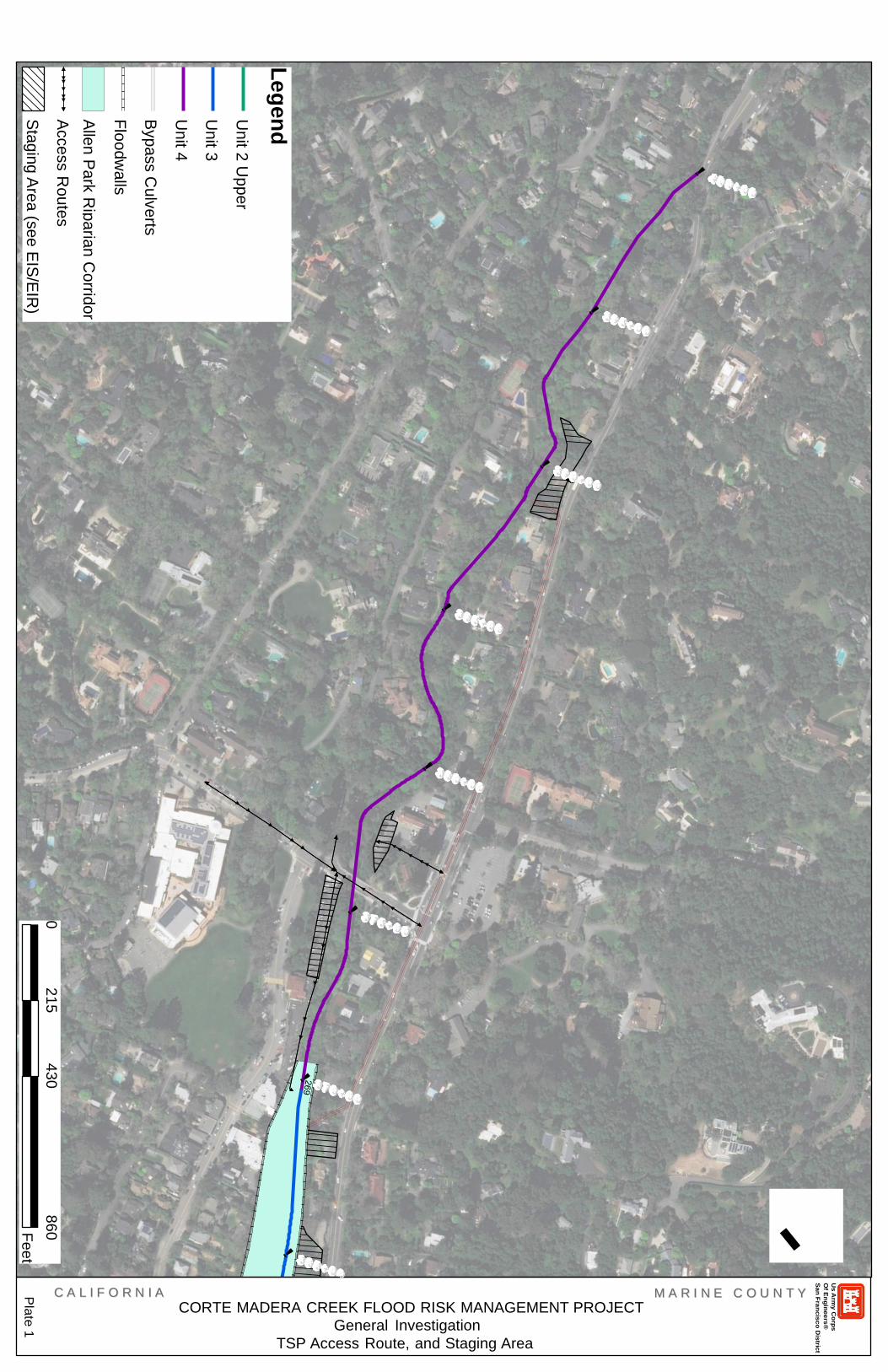
Attachment 2
Preliminary Proposed Access Route, and Staging Area Locations

Us Army Corps Of Engineers® San Francisco District
Plate 1
Plate 2
Plate 3
Plate 4
Plate 5
Plate
Legend
Unit 2 Upper
Unit 3
Unit 4
Bypass Culverts
Floodwalls
Allen Park Riparian Corridor
Access Routes
Staging Area (see EIS/EIR)
0 500
1,000 2,000
Feet
CC AA
LL II FF
OO RR
NN II AA
C
OR
TE
MA
DE
RA
CR
EE
K F
LO
OD
RIS
K M
AN
AG
EM
EN
T P
RO
JE
CT
MM AA
RR II NN
EE
Ge
ne
ral In
ve
stig
atio
n
TS
P A
cce
ss R
oute
, and S
tag
ing A
rea
CC OO
UU NN
TT YY

CC AA LL II FF OO RR NN II AA CORTE MADERA CREEK FLOOD RISK MANAGEMENT PROJECT
General Investigation
TSP Access Route, and Staging Area
MM AA RR II NN EE CC OO UU NN TT YY
Us
Arm
y C
orp
s
Of E
ng
ine
ers
®
San
Fra
nc
isc
o D
istric
t
Le
gen
d
Un
it 2 U
pp
er
Un
it 3
Un
it 4
Byp
ass C
ulv
erts
Flo
od
wa
lls
Alle
n P
ark
Rip
aria
n C
orrid
or
Acce
ss R
ou
tes
Sta
gin
g A
rea
(se
e E
IS/E
IR)
0
21
5
43
0
86
0
Fe
et
Pla
te 2
CC AA LL II FF OO RR NN II AA MM AA RR II NN EE CC OO UU NN TT YY
CORTE MADERA CREEK FLOOD RISK MANAGEMENT PROJECT
General Investigation
TSP Access Route, and Staging Area
Us
Arm
y C
orp
s
Of E
ng
ine
ers
®
San
Fra
nc
isc
o D
istric
t
Le
gen
d
Un
it 2 U
pp
er
Un
it 3
Un
it 4
Byp
ass C
ulv
erts
Flo
od
wa
lls
Alle
n P
ark
Rip
aria
n C
orrid
or
Acce
ss R
ou
tes
Sta
gin
g A
rea
(se
e E
IS/E
IR)
0
21
5
43
0
86
0
Fe
et
Pla
te 1

CC AA LL II FF OO RR NN II AA CORTE MADERA CREEK FLOOD RISK MANAGEMENT PROJECT
MM AA RR II NN EE CC OO UU NN TT YY
General Investigation
TSP Access Route, and Staging Area
Us
Arm
y C
orp
s
Of E
ng
ine
ers
®
San
Fra
nc
isc
o D
istric
t
Le
gen
d
Un
it 2 U
pp
er
Un
it 3
Un
it 4
Byp
ass C
ulv
erts
Flo
od
wa
lls
Alle
n P
ark
Rip
aria
n C
orrid
or
Acce
ss R
ou
tes
Sta
gin
g A
rea
(se
e E
IS/E
IR)
0
17
5
35
0
70
0
Fe
et
Pla
te 3

CC AA LL II FF OO RR NN II AA CORTE MADERA CREEK FLOOD RISK MANAGEMENT PROJECT
MM AA RR II NN EE CC OO UU NN TT YY
General Investigation
TSP Access Route, and Staging Area
Us
Arm
y C
orp
s
Of E
ng
ine
ers
®
San
Fra
nc
isc
o D
istric
t
Le
gen
d
Un
it 2 U
pp
er
Un
it 3
Un
it 4
Byp
ass C
ulv
erts
Flo
od
wa
lls
Alle
n P
ark
Rip
aria
n C
orrid
or
Acce
ss R
ou
tes
Sta
gin
g A
rea
(se
e E
IS/E
IR)
0
20
5
41
0
82
0
Fe
et
Pla
te 4

CC AA LL II FF OO RR NN II AA CORTE MADERA CREEK FLOOD RISK MANAGEMENT PROJECT
MM AA RR II NN EE CC OO UU NN TT YY
General Investigation
TSP Access Route, and Staging Area
Us
Arm
y C
orp
s
Of E
ng
ine
ers
®
San
Fra
nc
isc
o D
istric
t
Le
gen
d
Un
it 2 U
pp
er
Un
it 3
Un
it 4
Byp
ass C
ulv
erts
Flo
od
wa
lls
Alle
n P
ark
Rip
aria
n C
orrid
or
Acce
ss R
ou
tes
Sta
gin
g A
rea
(se
e E
IS/E
IR)
0
24
0
48
0
96
0
Fe
et
Pla
te 5
Attachment 3
Preliminary Detailed Layout Plan
(Pending)

Attachment 4
Preliminary Cross Sections

CC AA LL II FF OO RR NN II AA CORTE MADERA CREEK FLOOD RISK MANAGEMENT PROJECT
General Investigation
Prelemenary Cross Sections
MM AA RR II NN EE CC OO UU NN TT YY
Us
Arm
y C
orp
s
Of E
ng
ine
ers
®
San
Fra
nc
isc
o D
istric
t

Attachment 5
Utility Within Vicinity of the Selected Plan

Legend
Us Army Corps
Of Engineers®
San Francisco District
Unit 4
Bypass Culverts
Unit 3
Unit 2 Upper
Stormwater_Lines
COM Lines
<all other values>
Type_of_utility
Chilled Water
Communications
Electric
Electric (Lighting)
Fire Alarm
Fire Water
Gas
Geothermal
Irrigation
Joint Trench
Sanitary Sewer
Storm Drain
Unidentified
Water
Comcast Lines
Electric Lines
● Electric Points
Gas Lines
$+ Gas Points
Sewer Lines
● Sewer Points
AT&T Lines
● AT&T Points
Water Lines
Allen Park R.Corridor
Plate 1
Plate 2
Plate 3
Plate 4
Plate 5
Pl
0 500 1,000 2,000
Feet
CO
RT
E M
AD
ER
A C
RE
EK
FL
OO
D R
ISK
MA
NA
GE
ME
NT
ST
UD
Y
Ge
ne
ral In
ve
stig
atio
n
CC C AA A
LL L II I FF F
OO O RR R
NN N II I
AA A
MM M AA A
RR R II I NN N
EE E CC C
OO O UU U
NN N TT T
YY Y
Utilit
ies

Us Army Corps
Of Engineers®
San Francisco District
Plate 1
Legend
Bypass Culverts
SDP-15
WP-151WP-59 SSP-23 WP-138WP-16 GP-03
EP-01 SDP-16
CP-01
EP-03 EP-02 WP-72
SDP-17 WP-152 WP-153WP-154
SDP-48 SSP-32
SDP-14 EP-08 WP-73 WP-74
TP-01 EP-07
EP-11WP-75
EP-13
TP-02
TP-03
EP-15 WP-76 SDP-11 WP-19
WP-67
SDP-18 GP-04 SSP-08
GP-02 WP-156
GP-01 SDP-19 EP-21
EP-12 WP-77SDP-10
EP-22
GP-05
SDP-20
EP-14
0 105 210 420
Feet
CC C AA A
LL L II I FF F
OO O RR R
NN N II I
AA A
CO
RT
E M
AD
ER
A C
RE
EK
FLO
OD
RIS
K M
AN
AG
EM
EN
T S
TU
DY
MM M
AA A RR R
II I NN N
EE E CC C
OO O UU U NN N
TT T YY Y
Gene
ral I
nvestigation
Utilit
ies
Allen Park R.Corridor
Floodwalls
Unit 4
Unit 3
Unit 2 Upper
Stormwater_Lines
COM Lines
<all other values>
Type_of_utility
Chilled Water
Communications
Electric
Electric (Lighting)
Fire Alarm
Fire Water
Gas
Geothermal
Irrigation
Joint Trench
Sanitary Sewer
Storm Drain
Unidentified
Water
Comcast Lines
Electric Lines
● Electric Points
Gas Lines
$+ Gas Points
Sewer Lines
● Sewer Points
AT&T Lines
● AT&T Points
Water Lines
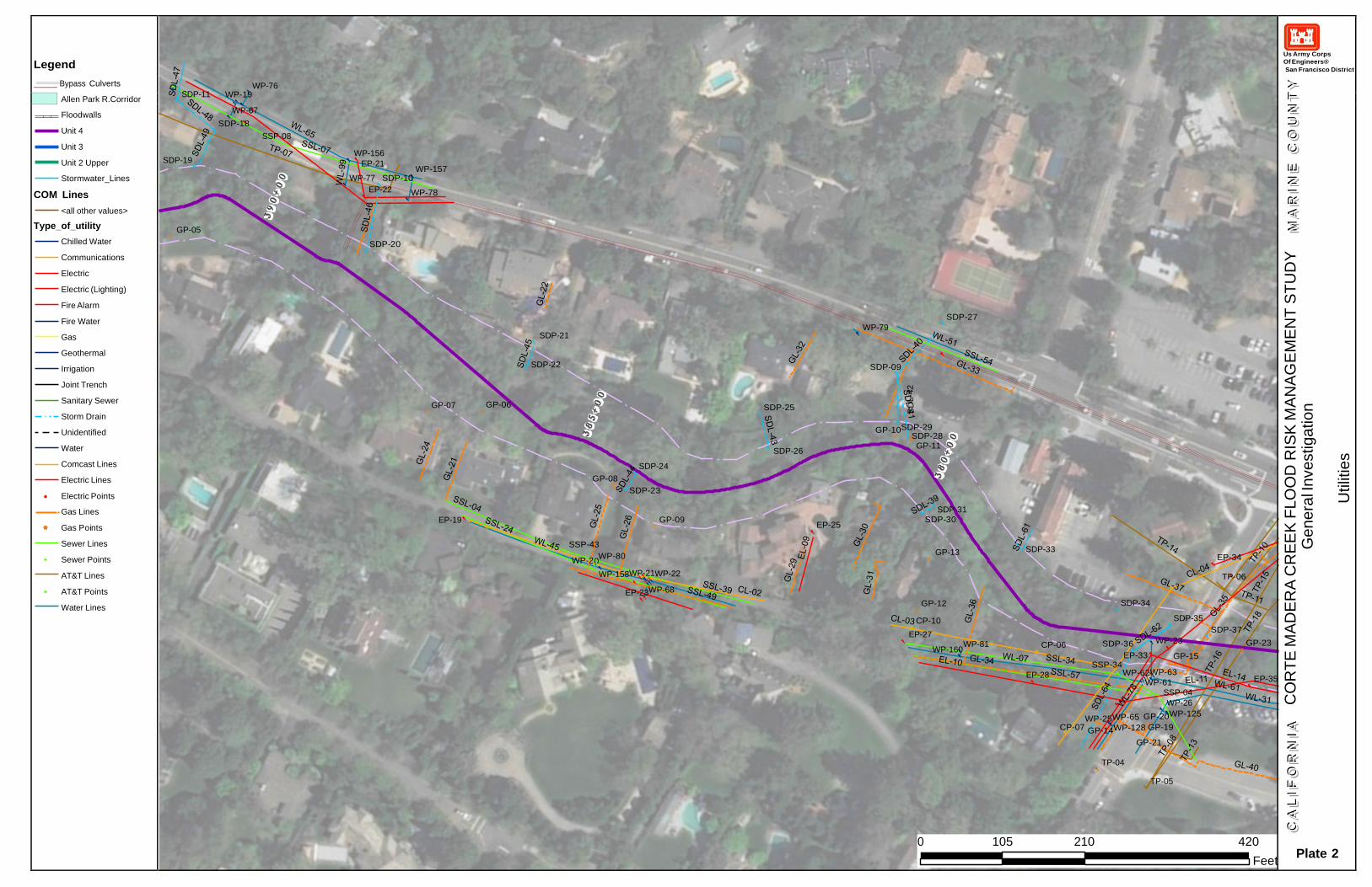
0
SDP-11
WP-76
WP-19
WP-67
SDP-18
Us Army Corps
Of Engineers®
San Francisco District
SDP-19
SSP-08
WP-156
EP-21
WP-157
WP-77 SDP-10
EP-22 WP-78
GP-05
SDP-20
SDP-21
WP-79
SDP-27
SDP-22
SDP-09
GP-07 GP-06
EP-19
GP-08
SSP-43
WP-2 WP-80
SDP-24
SDP-23
GP-09
SDP-25
SDP-26
EP-25
GP-10SDP-29 SDP-28 GP-11
SDP-31
SDP-30
GP-13
SDP-33
EP-34
WP-158WP-21WP-22
EP-23WP-68
GP-12
CP-10
EP-27
WP-160
WP-81
CP-06
SDP-34
SDP-36
EP-33
SDP-35
WP-23
GP-15
TP-06
SDP-37
GP-23
EP-28
SSP-34 WP-62WP-63
WP-61
SSP-04
WP-26
WP-25WP-65 GP-20WP-125
CP-07 GP-14WP-128 GP-19
GP-21
EP-35
TP-04
TP-05
0 105 210 420
Feet
Plate 2
Legend
Bypass Culverts
S
DL-4
2
CC C AA A
LL L II I FF F
OO O RR R
NN N II I
AA A
CO
RT
E M
AD
ER
A C
RE
EK
FLO
OD
RIS
K M
AN
AG
EM
EN
T S
TU
DY
MM M
AA A RR R
II I NN N
EE E CC C
OO O UU U NN N
TT T YY Y
Gene
ral I
nvestigation
Utilit
ies
Allen Park R.Corridor
Floodwalls
Unit 4
Unit 3
Unit 2 Upper
Stormwater_Lines
COM Lines
<all other values>
Type_of_utility
Chilled Water
Communications
Electric
Electric (Lighting)
Fire Alarm
Fire Water
Gas
Geothermal
Irrigation
Joint Trench
Sanitary Sewer
Storm Drain
Unidentified
Water
Comcast Lines
Electric Lines
● Electric Points
Gas Lines
$+ Gas Points
Sewer Lines
● Sewer Points
AT&T Lines
● AT&T Points
Water Lines

TP-09 !
Us Army Corps
Of Engineers®
San Francisco District
WP-119
CP-13 SSP-18 WP-120
EP-40 SDP-07
SSP-10
WP-164
WP-163
WP-166WP-168
WP-89WP-92WP-94
EP-42
CP-14 WP-86
GP-27
EP-49
WP-88WP-91
CP-15
WP-170
EP-51
WP-172
WP-171
WP-93
WP-173
EP-45
WP-174
SDP-46
EP-56
SDP-39SDP-40
GP-28 GP-29 EP-52
CP-17
EP-46
CP-18 WP-122
EP-62EP-47 EP-55
WP-124
SSP-26
WP-02
WP-29 WP-126
SDP-41 WP-87
SDP-43
SSP-27
SDP-45
SSP-06
GP-32 CP-19 CP-20EP-63
EP-65
EP-64
SDP-08 WP-85
WP-66
WP-31
WP-167 WP-03
SDP-47
SDP-51
WP-165
EP-58
WP-32
SDP-44
WP-90
EP-60
GP-26
GP-25
GP-30
GP-31
SDP-52
SDP-53
SSP-17
SDP-50
EP-61
EP-66
GP-33
CP-23
EP-67
SSP-41
CP-22
CP-21
SDP-54
EP-68
EP-69
WP-64WP-95
WP-35
WP-05
0 105 210 420
Feet
Plate 3
Legend
Bypass Culverts
W
L-1
25
CC C AA A
LL L II I FF F
OO O RR R
NN N II I
AA A
CO
RT
E M
AD
ER
A C
RE
EK
FLO
OD
RIS
K M
AN
AG
EM
EN
T S
TU
DY
MM M
AA A RR R
II I NN N
EE E CC C
OO O UU U NN N
TT T YY Y
Gene
ral I
nvestigation
Utilit
ies
Allen Park R.Corridor
Floodwalls
Unit 4
Unit 3
Unit 2 Upper
Stormwater_Lines
COM Lines
<all other values>
Type_of_utility
Chilled Water
Communications
Electric
Electric (Lighting)
Fire Alarm
Fire Water
Gas
Geothermal
Irrigation
Joint Trench
Sanitary Sewer
Storm Drain
Unidentified
Water
Comcast Lines
Electric Lines
● Electric Points
Gas Lines
$+ Gas Points
Sewer Lines
● Sewer Points
AT&T Lines
● AT&T Points
Water Lines

Us Army Corps
Of Engineers®
San Francisco District
WP-176
WP-97
CP-26
EP-76 WP-99
GP-37
EP-77
GP-38
SSP-14
GP-39 GP-40
GP-43
COMP-247
COMP-381
COMP-367
COMP-294
GP-42
SDP-05 SDP-04 SDP-59
GP-44
COMP-324
COMP-325
COMP-362
COMP-321COMP-364 SDP-57 SDP-58 COMP-317 COMP-07
COMP-118
COMP-306 COMP-23
COMP-88COMP-87
GP-41
WP-08WP-38
SSP-37
COMP-314 SSP-31
COMP-67 COMP-90 COMP-08
COMP-65
COMP-26 COMP-356
COMP-24
COMP-12
COMP-62
COMP-86
COMP-50
SDP-60 SDP-61 COMP-348COMP-354
COMP-64
COMP-370
COMP-320 TP-16
COMP-36
WP-100
COMP-123COMP-141COMP-143
SDP-62
COMP-341
COMP-344
SDP-63
COMP-21COMP-63
SSP-16
COMP-49
SDP-64
COMP-43
COMP-268
COMP-72
WP-39
WP-40
WP-130
COMP-129
COMP-373COMP-44
COMP-139
COMP-351SDP-65 COMP-15 COMP-208
2
COMP-176 COMP-5
COMP-92 COMP-216 COMP-140
COMP-199COMP-221 COMP-223 COMP-203
COMP-255
COMP-182
WP-41 COMP-184
COMP-162
COMP-192
COMP-219 COMP-200COMP-265
COMP-93
TP-11 COMP-85
COMP-291
COMP-116
COMP-174
COMP-175
COMP-326
COMP-336
COMP-121
COMP-177 COMP-333
0 95 190 380
Feet
Plate 4
Legend
Bypass Culverts
C
OM
L-5
92
CC C AA A
LL L II I FF F
OO O RR R
NN N II I
AA A
CO
RT
E M
AD
ER
A C
RE
EK
FLO
OD
RIS
K M
AN
AG
EM
EN
T S
TU
DY
MM M
AA A RR R
II I NN N
EE E CC C
OO O UU U NN N
TT T YY Y
Gene
ral I
nvestigation
Utilit
ies
Allen Park R.Corridor
Floodwalls
Unit 4
Unit 3
Unit 2 Upper
Stormwater_Lines
COM Lines
<all other values>
Type_of_utility
Chilled Water
Communications
Electric
Electric (Lighting)
Fire Alarm
Fire Water
Gas
Geothermal
Irrigation
Joint Trench
Sanitary Sewer
Storm Drain
Unidentified
Water
Comcast Lines
Electric Lines
● Electric Points
Gas Lines
$+ Gas Points
Sewer Lines
● Sewer Points
AT&T Lines
● AT&T Points
Water Lines
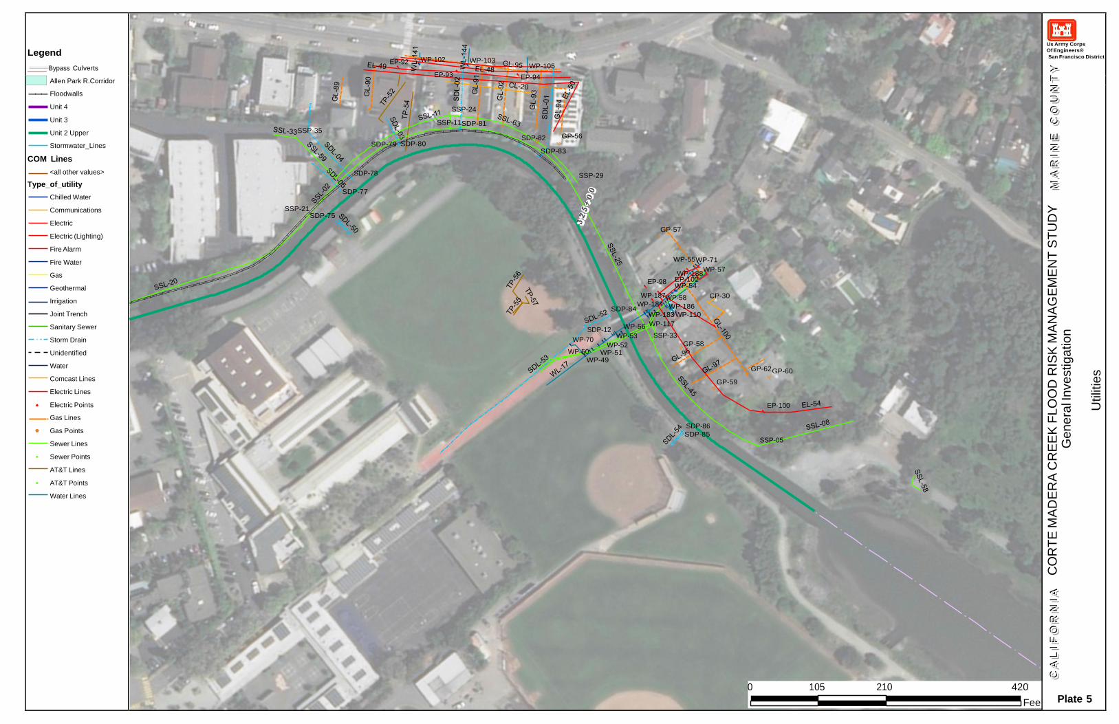
Us Army Corps
Of Engineers®
San Francisco District
Plate 5
Legend
Bypass Culverts
EP-92 WP-102 WP-103 WP-105
EP-93 EP-94
SSP-24
SSP-11SDP-81 SSP-35
SDP-82 GP-56 SDP-79 SDP-80
SDP-83
SDP-78 SSP-29
SDP-77
SSP-21
SDP-75
GP-57
WP-55WP-71
WP-188WP-57
EP-98 EP-102 WP-54
WP-187WP-58 CP-30
WP-184 WP-186 SDP-84
WP-183 WP-110
SDP-12 WP-56 WP-117
WP-70 WP-53 SSP-33
WP-52 GP-58 WP-50 WP-51
WP-49
GP-62 GP-60
GP-59
EP-100
SDP-86
SDP-85 SSP-05
0 105 210 420
Feet
CC C AA A
LL L II I FF F
OO O RR R
NN N II I
AA A
CO
RT
E M
AD
ER
A C
RE
EK
FLO
OD
RIS
K M
AN
AG
EM
EN
T S
TU
DY
MM M
AA A RR R
II I NN N
EE E CC C
OO O UU U NN N
TT T YY Y
Gene
ral I
nvestigation
Utilit
ies
Allen Park R.Corridor
Floodwalls
Unit 4
Unit 3
Unit 2 Upper
Stormwater_Lines
COM Lines
<all other values>
Type_of_utility
Chilled Water
Communications
Electric
Electric (Lighting)
Fire Alarm
Fire Water
Gas
Geothermal
Irrigation
Joint Trench
Sanitary Sewer
Storm Drain
Unidentified
Water
Comcast Lines
Electric Lines
● Electric Points
Gas Lines
$+ Gas Points
Sewer Lines
● Sewer Points
AT&T Lines
● AT&T Points
Water Lines

Attachment 6
Concept Structural Details
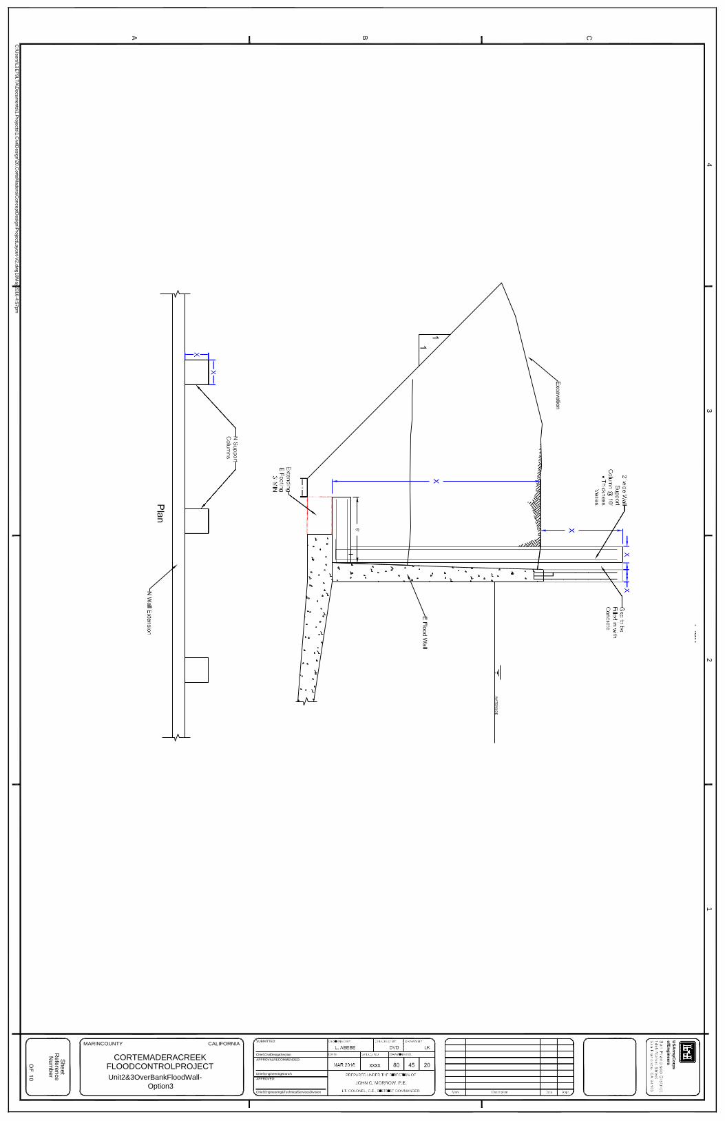
MARINCOUNTY CALIFORNIA
CORTEMADERACREEK FLOODCONTROLPROJECT
Unit2&3OverBankFloodWall-
Option3
SUBMITTED:
Chief,CivilDesignSection
APPROVALRECOMMENDED:
Chief,EngineeringBranch
APPROVED:
Chief,Engineering&TechnicalServicesDivision
4
3
2
1
US
Arm
yC
orp
s
ofE
ng
ineers
C
B
A
Sh
ee
t R
efe
ren
ce
N
um
be
r
C:\U
sers
\L3
ET
9LT
A\D
ocu
ments
\1.P
roje
cts
\1.C
ivilD
esig
n\2
0.C
orte
Madera
\Co
nce
ptD
esig
n\P
roje
ctL
ayou
t-V2.d
wg1
8M
ay2
016
-4:5
7pm

MARINCOUNTY CALIFORNIA
CORTEMADERACREEK FLOODCONTROLPROJECT
OverBankFloodWallandSetBack
FloodWall
SUBMITTED:
Chief,CivilDesignSection
APPROVALRECOMMENDED:
Chief,EngineeringBranch
APPROVED:
Chief,Engineering&TechnicalServicesDivision
4
3
2
1
US
Arm
yC
orp
s
ofE
ng
ineers
C
B
A
Sh
ee
t R
efe
ren
ce
N
um
be
r
C:\U
sers
\L3
ET
9LT
A\D
ocu
ments
\1.P
roje
cts
\1.C
ivilD
esig
n\2
0.C
orte
Madera
\Co
nce
ptD
esig
n\P
roje
ctL
ayou
t-V2.d
wg1
8M
ay2
016
-4:5
7pm
Related Documents