California Mobile Home WIS • 7/18/05 Draft APPENDIX -B- METHODS FOR ESTIMATING AND MEASURING AIRFLOW

Welcome message from author
This document is posted to help you gain knowledge. Please leave a comment to let me know what you think about it! Share it to your friends and learn new things together.
Transcript

California Mobile Home WIS • 7/18/05 Draft
APPENDIX -B-
METHODS FOR ESTIMATING AND MEASURING AIRFLOW

Appendix -B-
B-1 California Mobile Home WIS Appendix -B- © RHA • 7/18/05 Draft PART I: METHODS FOR ESTIMATING AIRFLOW
CONTENTS
PART I: SUGGESTED METHODS FOR ESTIMATING AIRFLOW
1. Air Conditioning Capacity (Tons)
- The Preston Guide or Carrier Blue Book - Model Number Nomenclature
2. Heating System Capacity (kBtuh)
- Btu Output of Gas Furnace
- Wattage of Electric Furnace
PART II: APPROVED METHODS FOR MEASURING AIRFLOW
1. Flow Grid Measurement
2. Plenum Pressure Matching Measurement (Duct Tester Used as a Pow-ered Capture Hood)
3. Using A Flow Capture Hood
Appendix -B-
B-2 California Mobile Home WIS Appendix -B- © RHA • 7/18/05 Draft PART I: METHODS FOR ESTIMATING AIRFLOW
METHODS FOR ESTIMATING AND MEASURING AIRFLOW
PART I – METHODS FOR ESTIMATING AIRFLOW
1. METHODS
- The following methods are outlined in this Appendix: • Air Conditioning Capacity (Tons)
- The Preston Guide or Carrier Blue Book - Model Number Nomenclature
• Heating System Capacity (kBtuh Output) - Btuh Output of Gas Furnace - Wattage of Electric Furnace
- Air Conditioner or Heat Pump • AC/HP unit capacity may be determined by the following methods us-
ing information obtained from the condenser nameplate: - A-1: The Preston Guide or Carrier Blue Book - A-2: Model Number Nomenclature
- Gas or Electric Furnace • Furnace capacity may be determined by using the unit’s Btuh Output.
- Gas: Directly from the nameplate - Electric: Wattage converted to Btuh Output
EXAMPLE OF A CONDENSER NAMEPLATE
Appendix -B-
B-3 California Mobile Home WIS Appendix -B- © RHA • 7/18/05 Draft PART I: METHODS FOR ESTIMATING AIRFLOW
2. AIR CONDITIONER AND HEAT PUMP UNITS - Method A—Preston Guide or Carrier Bluebook
• Step A-1: Determine the model number and date of manufacture from the condenser nameplate.
NAMEPLATE SHOWS MODEL NUMBER TO BE “UAKA-036JAS”
NAMEPLATE SHOWS DATE OF MANUFACTURE TO BE “09/93”

Appendix -B-
B-4 California Mobile Home WIS Appendix -B- © RHA • 7/18/05 Draft PART I: METHODS FOR ESTIMATING AIRFLOW
2. AIR CONDITIONER AND HEAT PUMP UNITS (continued) - Method A—Preston Guide or Carrier Bluebook (continued)
• Step A-2: Check the Preston Guide (or Carrier Bluebook) to deter-mine cooling capacity of the unit, based on model number and date of manufacture. - Find model number UAKA-036JA manufactured in 1993. - Find cooling capacity, which in this example is 34,400 Btu.
Preston Guide
DATA FROM THE PRESTON GUIDE SHOWS UNIT’S COOLING CAPACITY TO BE 34,000 BTU
Appendix -B-
B-5 California Mobile Home WIS Appendix -B- © RHA • 7/18/05 Draft PART I: METHODS FOR ESTIMATING AIRFLOW
2. AIR CONDITIONER AND HEAT PUMP UNITS (continued) - Method A—Preston Guide or Carrier Bluebook (continued)
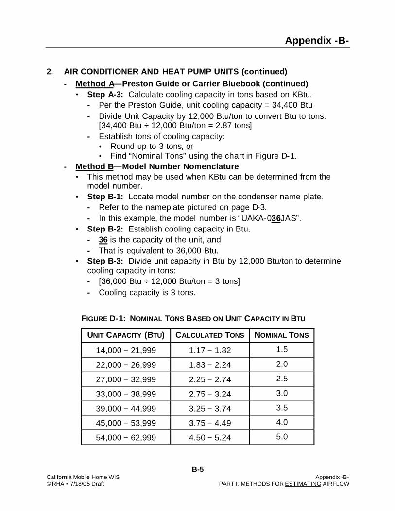
• Step A-3: Calculate cooling capacity in tons based on KBtu. - Per the Preston Guide, unit cooling capacity = 34,400 Btu - Divide Unit Capacity by 12,000 Btu/ton to convert Btu to tons:
[34,400 Btu ÷ 12,000 Btu/ton = 2.87 tons] - Establish tons of cooling capacity:
• Round up to 3 tons, or • Find “Nominal Tons” using the chart in Figure D-1.
- Method B—Model Number Nomenclature • This method may be used when KBtu can be determined from the
model number. • Step B-1: Locate model number on the condenser name plate.
- Refer to the nameplate pictured on page D-3. - In this example, the model number is “UAKA-036JAS”.
• Step B-2: Establish cooling capacity in Btu. - 36 is the capacity of the unit, and - That is equivalent to 36,000 Btu.
• Step B-3: Divide unit capacity in Btu by 12,000 Btu/ton to determine cooling capacity in tons: - [36,000 Btu ÷ 12,000 Btu/ton = 3 tons] - Cooling capacity is 3 tons.
FIGURE D-1: NOMINAL TONS BASED ON UNIT CAPACITY IN BTU
UNIT CAPACITY (BTU) CALCULATED TONS NOMINAL TONS
14,000 − 21,999 1.17 − 1.82 1.5
22,000 − 26,999 1.83 − 2.24 2.0
27,000 − 32,999 2.25 − 2.74 2.5
33,000 − 38,999 2.75 − 3.24 3.0
39,000 − 44,999 3.25 − 3.74 3.5
45,000 − 53,999 3.75 − 4.49 4.0
54,000 − 62,999 4.50 − 5.24 5.0

Appendix -B-
B-6 California Mobile Home WIS Appendix -B- © RHA • 7/18/05 Draft PART I: METHODS FOR ESTIMATING AIRFLOW
3. FURNACES - System G: Determining Estimated Airflow for Gas Furnaces
• Step G-1: Determine Btuh output from unit name plate. - Locate Btuh output on the nameplate (see picture below).
• Output is 80,000 Btuh in this example. - If only Input is listed, Output = Input x (% efficiency).
• Example: (100 kBtuh Input) x (0.80 AFUE) = 80 kBtuh. • Step G-2: Convert Btuh output to estimated airflow in cfm.
- Assume 21.7 cfm per kBtuh. - Use the following equation to determine estimated airflow:
[Output kBtuh x 21.7 cfm/kBtuh = cfm system airflow] - Example:
[80 (kBtuh) x 21.7 (cfm/KBtu) = 1,736 cfm system airflow]
EXAMPLE OF A GAS FURNACE NAMEPLATE SHOWING HEATING CAPACITY (OUTPUT) OF 80,000 BTUH

Appendix -B-
B-7 California Mobile Home WIS Appendix -B- © RHA • 7/18/05 Draft PART I: METHODS FOR ESTIMATING AIRFLOW
3. FURNACES (continued) - System E: Determining Estimated Airflow for Electric Furnaces
• Step E-1: Determine wattage from unit name plate. - Locate heating capacity (in kilowatts) on the nameplate (see
graphic below). - Heating Capacity (output) is 20 kilowatts in this example
- Step E-2: Convert kilowatts to kBtuh output to estimated airflow in
cfm, assuming 3.413 kBtuh per kilowatt and 95% efficiency. - Use the following formula to convert wattage to kBtuh output:
• [(watts x 3.413 x 0.95) = Btuh output] or • [(kilowatts x 3.242) = kBtuh output] • In this example:
[20 (kW) x 3.242 = 64.84 kBtuh output]. • Step E-3: Convert kBtuh output to estimated airflow in cfm.
- Assume 21.7 cfm per kBtuh.* - Use the following equation to determine estimated airflow:
[kBtuh x 21.7 cfm/kBtuh = cfm system airflow] - Example:
[64.84 (kBtuh) x 21.7 (cfm/KBtu) = 1407 cfm system airflow] *May be used until CEC determines cfm/kBtuh default for electric furnaces.
EXAMPLE OF AN ELECTRIC FURNACE NAMEPLATE SHOWING HEATING CAPACITY OF 6,900 WATTS
(TEMPORARY GRAPHIC)
ELECTRIC FURNACE SIMULATED NAMEPLATE
MANUFACTURED BY XYZ FURNACE CORP.
MODEL # 000000000 SERIAL # 00000000
HEATING CAPACITY: 20 KILOWATTS

Appendix -B-
B-8 California Mobile Home WIS Appendix -B- © RHA • 7/18/05 Draft PART II: METHODS FOR MEASURING AIRFLOW
PART II – METHODS FOR MEASURING AIRFLOW Methods for measuring HVAC system airflow (fan flow) presented in this appen-dix are methods approved by the California Energy Commission and described in Appendix RE-2005 of the Title 24 “Residential Alternative Calculation Method (ACM) Approval Manual for the 2005 Building Energy Efficiency Standards for Residential and Nonresidential Buildings” — Publication 400-03-003F, available online at: http://www.energy.ca.gov/title24/2005standards/index.html
1. FLOW GRID MEASUREMENT
- Overview • This method uses a “metering plate” containing “pressure sensing
grids”, which are directed toward the air handler. • The metering plate temporarily replaces the filter in a typical air han-
dler system during the air flow measurement procedure. - If the filter location is directly adjacent to the air handler, the meter-
ing plate will measure the total air handler flow. - If the filter is located remotely at a single central return, the meter-
ing plate will measure the air flow through the central return. Air-flow measurement through the central return will be very close to the total air handler air flow only if the return duct is very tight.
FLOW GRID (METERING PLATE) WITH PRESSURE SENSING GRIDS DIRECTED TOWARD AIR HANDLER
TUBING TO GAUGE
RETURN GRILLE
RETURN OPENING MOBILE HOME
GRAPHIC NEEDED

Appendix -B-
B-9 California Mobile Home WIS Appendix -B- © RHA • 7/18/05 Draft PART II: METHODS FOR MEASURING AIRFLOW
SUPPLY PLENUM
STATIC PRESSURE PROBE DIRECTED INTO SUPPLY AIRFLOW
1. FLOW GRID MEASUREMENT (continued) - Protocol
• Equipment used for measurements shall meet the requirements speci-fied in ACM Residential Manual Appendix RE-2005, §RE.3.1.3, “Flow Grid Measurement.”
• The following general guidelines are for reference only; measurement shall be: - Performed in accordance with test equipment manufacturer’s in-
structions, and - In harmony with ACM Residential Manual Appendix RE-2005,
§RE.4.1.3, “Diagnostic Fan Flow Using Flow Grid Measurement”.
- General Guidelines • Step 1: System operating pressure shall be measured with the air
handler operating at maximum speed used in the system. - Using a digital pressure gauge, pressure difference in Pa shall be
measured between the supply plenum and the conditioned space (Psp) using a static pressure probe pointing into the air stream.
- Probe may be placed in the nearest supply duct when access to the supply plenum is unavailable.
- Probe shall be adjusted to achieve the highest pressure and then se-cured in place during the fan flow test.
MOBILE HOME GRAPHIC NEEDED

Appendix -B-
B-10 California Mobile Home WIS Appendix -B- © RHA • 7/18/05 Draft PART II: METHODS FOR MEASURING AIRFLOW
1. FLOW GRID MEASUREMENT (continued) - General Guidelines (continued)
• Step 2: With the air handler off, the flow grid measurement sensor (metering plate) shall be installed, with the pressure sensing grids di-rected toward the air handler, and with no obstructions within 6" up-stream or 2" downstream of the metering plates, in the best available location (filter slot or filter grille) where all system airflow passes through the flow grid.
(A) When Using DG-700 Fully-Automated Digital Gauge • Step A-3: Air handler shall be operated again at the same speed as
used in Step 1, and time averaging shall be lengthened as needed to maximize accuracy when readings are fluctuating.
• Step A-4: Measured system airflow (Qah) shall be obtained from the digital pressure gauge and recorded.
• Step A-5: When the flow grid is installed in a remote filter grille, manufacturer’s correction factor shall be used to increase accuracy.
METERING PLATE INSTALLED IN FILTER SLOT, WITH FRONT SIDE FACING INTO THE AIRFLOW
AIRFLOW
MOBILE HOME GRAPHIC NEEDED

Appendix -B-
B-11 California Mobile Home WIS Appendix -B- © RHA • 7/18/05 Draft PART II: METHODS FOR MEASURING AIRFLOW
1. FLOW GRID MEASUREMENT (continued) - General Guidelines (continued)
(B) When Using DG-3 Digital Gauge • Step B-3: With air handler operating again at the same speed as in
Step 1, measurements shall be made with the flow grid in place: - System operating pressure re-measured (Ptest). - Airflow through the flow grid measured (Qgrid).
• Step B-4: System Airflow (Qah) shall be calculated by: - Multiplying Qgrid by equipment manufacturer’s Flow Resistance
Correction Factors (sample shown below), or - Applying the following equation to readings obtained in Steps 1
and B-3: System Airflow (Air Handler Flow) = Qah = Qgrid x (Psp/Ptest)0.5
• Step B-5: When the flow grid is installed in a remote filter grille, manufacturer’s correction factor shall be used to increase accuracy.
All Gauges • Step 6: Adjusted Airflow shall be calculated (to correct for differences
in system operating pressures measured in Steps 1 and 3) using manufacturer’s flow resistance correction procedure.
EXAMPLE OF FLOW RESISTANCE CORRECTION FAC TORS USED TO CALCULATE ADJUSTED AIRFLOW
Appendix -B-
B-12 California Mobile Home WIS Appendix -B- © RHA • 7/18/05 Draft PART II: METHODS FOR MEASURING AIRFLOW
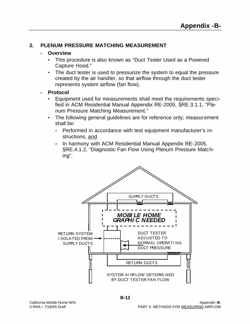
2. PLENUM PRESSURE MATCHING MEASUREMENT - Overview
• This procedure is also known as “Duct Tester Used as a Powered Capture Hood.”
• The duct tester is used to pressurize the system to equal the pressure created by the air handler, so that airflow through the duct tester represents system airflow (fan flow).
- Protocol • Equipment used for measurements shall meet the requirements speci-
fied in ACM Residential Manual Appendix RE-2005, §RE.3.1.1, “Ple-num Pressure Matching Measurement.”
• The following general guidelines are for reference only; measurement shall be: - Performed in accordance with test equipment manufacturer’s in-
structions, and - In harmony with ACM Residential Manual Appendix RE-2005,
§RE.4.1.2, “Diagnostic Fan Flow Using Plenum Pressure Match-ing”.
FAU DUCT TESTER ADJUSTED TO NORMAL OPERATING DUCT PRESSURE
SUPPLY DUCTS
RETURN DUCTS
SYSTEM AIRFLOW DETERMINED BY DUCT TESTER FAN FLOW
RETURN SYSTEM ISOLATED FROM
SUPPLY DUCTS
MOBILE HOME GRAPHIC NEEDED

Appendix -B-
B-13 California Mobile Home WIS Appendix -B- © RHA • 7/18/05 Draft PART II: METHODS FOR MEASURING AIRFLOW
SUPPLY PLENUM
STATIC PRESSURE PROBE DIRECTED INTO SUPPLY AIRFLOW
2. PLENUM PRESSURE MATCHING MEASUREMENT (continued) - General Guidelines
• Step 1: Supply plenum pressure test set-up: - Air handler shall be off. - Doors, windows, etc. shall be open to prevent pressure changes in
the space containing the handler (e.g., outside door/window for air handler in conditioned space; or access doors, vents, etc. for air handler in garage, attic, etc.).
- All supply and return registers shall be open, and filter(s) clean. - Static pressure probe, directed into the airflow, shall be inserted
into the supply plenum or in a supply trunk nearby. It shall be ad-justed (rotated) to achieve the highest pressure and securely at-tached.
- Tubing from the probe shall be attached to Channel A Input tap of the digital pressure gauge, and the Reference tap shall be open to the conditioned space.
• Step 2: With the air handler fan operating at the maximum speed used in the system (e.g., cooling speed when air conditioning is pre-sent), the pressure difference in Pa between the supply plenum and the conditioned space (Psp) shall be measured. Psp, the normal operating duct pres-sure, is the target pressure to be maintained during the sys-tem airflow (fan flow) tests.
MOBILE HOME GRAPHIC NEEDED

Appendix -B-
B-14 California Mobile Home WIS Appendix -B- © RHA • 7/18/05 Draft PART II: METHODS FOR MEASURING AIRFLOW
2. PLENUM PRESSURE MATCHING MEASUREMENT (continued) - General Guidelines
• Step 3: Duct Tester set-up at air handler cabinet:* - With the air handler access panel removed, the return air opening
inside the air handler cabinet shall be sealed (e.g., with cardboard and tape) to isolate the return system from the supply system.
- The Duct Tester shall be installed in place of the air handler access panel. If air handler components will obstruct airflow, the Duct Tester shall be mounted on an extension/box (illustrated below) that holds it away from the furnace cabinet.
- Tubing shall connect the Duct Tester to the Channel B Input tap on the digital pressure gauge, and the Reference tap shall be open to space where the Duct Tester is located.
*Attachment to the return grille of a single-return system (pictured on page D-15) is possible. However, if the return duct is not substantially airtight, leaks will cause the airflow measurement to be inaccurate.
PLENUM PRESSURE MATCHING MEASUREMENT (DUCT TESTER USED AS A POWERED CAPTURE
HOOD)—WITH FAN ASSEMBLY EXTENDED AWAY FROM AIR HANDLER OBSTRUCTIONS
EXTENSION USED TO POSITION DUCT TESTER AWAY FROM AIR HANDLER COMPONENTS THAT
WOULD OBSTRUCT AIRFLOW FAU
DUCT TESTER FAN
MOBILE HOME GRAPHIC NEEDED

Appendix -B-
B-15 California Mobile Home WIS Appendix -B- © RHA • 7/18/05 Draft PART II: METHODS FOR MEASURING AIRFLOW
2. PLENUM PRESSURE MATCHING MEASUREMENT (continued) - General Guidelines (continued)
• Step 4: With the air handler operating, - Duct Tester shall be turned on and adjusted until the duct pressure
on Channel A equals the normal operating duct pressure (Psp) measured in Step 2.
- Airflow through the Duct Tester shall be determined (calculated or measured using the digital gauge fan flow feature), which is the es-timated cfm system airflow through the air handler (Qah).
• Step 5: Correction shall be made when Duct Tester cannot ade-quately pressurize the system to equal the normal operating duct pressure (Psp) recorded in Step 2: - With the Duct Tester producing the maximum attainable duct pres-
sure on Channel A (Pmax), the airflow through the Duct Tester (Qmax) shall be determined.
- System airflow at normal operating duct pressure (Psp) shall be estimated using the following equation:
- System (Air Handler) Airflow = Qah = Qmax x (Psp/Pmax) 0.5
OPTIONAL DUCT TESTER LOCATION AT A SINGLE-RETURN SYSTEM INLET (WHEN
RETURN DUCTWORK IS SUBSTANTIALLY AIRTIGHT)
DUCT TESTER FAN
SINGLE CENTRAL RETURN
MOBILE HOME GRAPHIC NEEDED
Appendix -B-
B-16 California Mobile Home WIS Appendix -B- © RHA • 7/18/05 Draft PART II: METHODS FOR MEASURING AIRFLOW
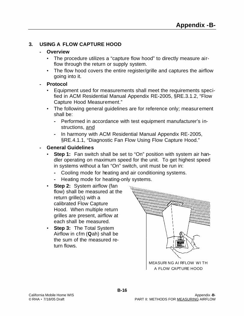
MEASURING AIRFLOW WITH A FLOW CAPTURE HOOD
3. USING A FLOW CAPTURE HOOD - Overview
• The procedure utilizes a “capture flow hood” to directly measure air-flow through the return or supply system.
• The flow hood covers the entire register/grille and captures the airflow going into it.
- Protocol • Equipment used for measurements shall meet the requirements speci-
fied in ACM Residential Manual Appendix RE-2005, §RE.3.1.2, “Flow Capture Hood Measurement.”
• The following general guidelines are for reference only; measurement shall be: - Performed in accordance with test equipment manufacturer’s in-
structions, and - In harmony with ACM Residential Manual Appendix RE-2005,
§RE.4.1.1, “Diagnostic Fan Flow Using Flow Capture Hood.” - General Guidelines
• Step 1: Fan switch shall be set to “On” position with system air han-dler operating on maximum speed for the unit. To get highest speed in systems without a fan “On” switch, unit must be run in: - Cooling mode for heating and air conditioning systems. - Heating mode for heating-only systems.
• Step 2: System airflow (fan flow) shall be measured at the return grille(s) with a calibrated Flow Capture Hood. When multiple return grilles are present, airflow at each shall be measured.
• Step 3: The Total System Airflow in cfm (Qah) shall be the sum of the measured re-turn flows.
Related Documents