1 0.00E+00 2.00E+08 4.00E+08 6.00E+08 8.00E+08 1.00E+09 1.20E+09 0 0.02 0.04 0.06 0.08 0.1 0.12 Moment [N*mm] Rotation [rad] Moment-Rotation Abaqus Data Analytical Moment Elastic Moment- Rotation Appendix 1 Appendix A Test The result of the test performed in order to validate the approach used in this master thesis. Angle of rotation formula in elastic behaviour for the corresponding static system: = 600 mm Young Modulus Moment of inertia E 200 10 3 N mm 2 I bh 3 12 6.3 10 9 mm 4

Welcome message from author
This document is posted to help you gain knowledge. Please leave a comment to let me know what you think about it! Share it to your friends and learn new things together.
Transcript
1
0.00E+00
2.00E+08
4.00E+08
6.00E+08
8.00E+08
1.00E+09
1.20E+09
0 0.02 0.04 0.06 0.08 0.1 0.12
Mo
me
nt
[N*m
m]
Rotation [rad]
Moment-Rotation
AbaqusData
AnalyticalMoment
ElasticMoment-Rotation
Appendix
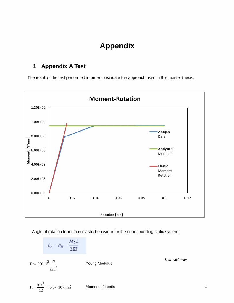
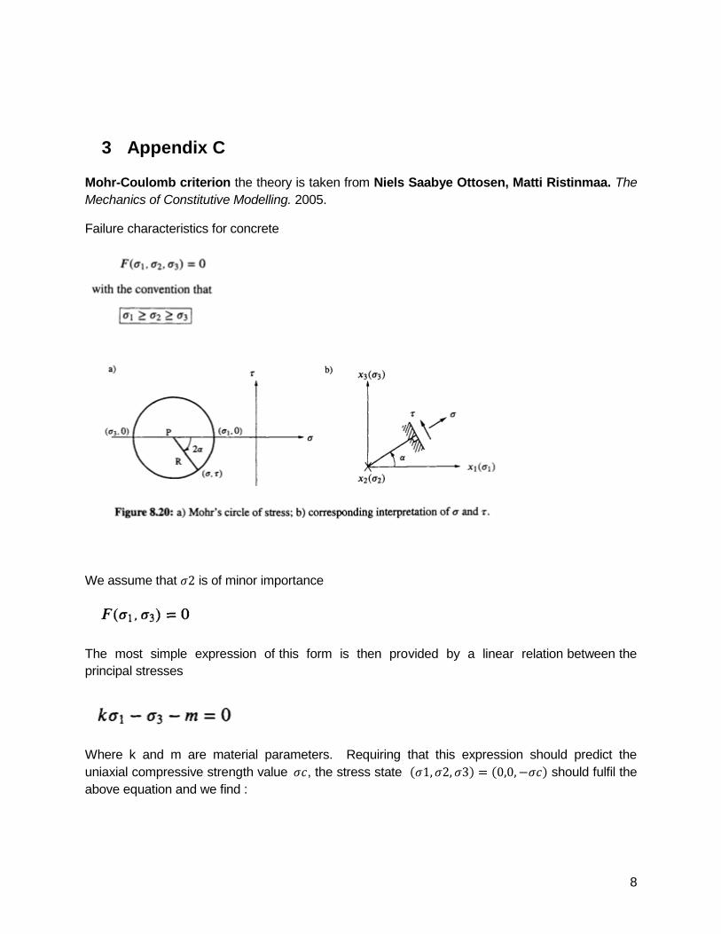
1 Appendix A Test
The result of the test performed in order to validate the approach used in this master thesis.
Angle of rotation formula in elastic behaviour for the corresponding static system:
𝐿 = 600 mm Young Modulus
Moment of inertia
E 200 103
N
mm2
Ib h
3
126.3 10
9 mm
4

2
The formula was used to find the elastic moment in respect to the rotation applied to the beam.
Moments Elastic
0
63000000
126000000
220500000
346500000
472500000
598500000
724500000
850500000
976500000
Analytical calculations
Yield stress
Length
Area
Moment
fy 30N
mm2
L 6000mm
h 600mm Height
Widthb 350mm
A h b 2.1 105
mm2
M1
2fy A
h
2
M 9.450 108
N mm

3
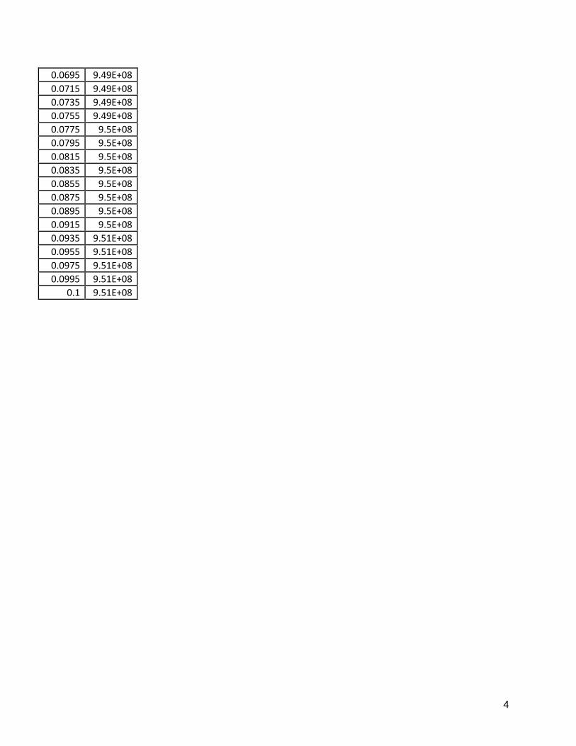
Abaqus data
Rotation Moments
0 0
0.001 59143400
0.002 1.18E+08
0.0035 2.07E+08
0.0055 3.25E+08
0.0075 4.44E+08
0.0095 5.62E+08
0.0115 6.8E+08
0.0135 7.89E+08
0.0155 8.02E+08
0.0175 8.14E+08
0.0195 8.26E+08
0.0215 8.38E+08
0.0235 8.5E+08
0.0255 8.62E+08
0.0275 8.74E+08
0.0295 8.86E+08
0.0315 8.98E+08
0.0335 9.1E+08
0.0355 9.23E+08
0.0375 9.35E+08
0.0395 9.43E+08
0.0415 9.46E+08
0.0435 9.47E+08
0.0455 9.48E+08
0.0475 9.48E+08
0.0495 9.48E+08
0.0515 9.48E+08
0.0535 9.48E+08
0.0555 9.48E+08
0.0575 9.48E+08
0.0595 9.48E+08
0.0615 9.49E+08
0.0635 9.49E+08
0.0655 9.49E+08
0.0675 9.49E+08
4
0.0695 9.49E+08
0.0715 9.49E+08
0.0735 9.49E+08
0.0755 9.49E+08
0.0775 9.5E+08
0.0795 9.5E+08
0.0815 9.5E+08
0.0835 9.5E+08
0.0855 9.5E+08
0.0875 9.5E+08
0.0895 9.5E+08
0.0915 9.5E+08
0.0935 9.51E+08
0.0955 9.51E+08
0.0975 9.51E+08
0.0995 9.51E+08
0.1 9.51E+08

5
2 Appendix B Analytical analysis
Singly reinforced beam
Radius of reinforcement
Area of steel
Yield strength of steel reinforcement
Compressive strength of concrete
Height of RC Beam
Concrete cover
Ultimate strain in concrete
Effective depth
Young modulus of elasticity
Yield strain
Neutral axis
Strain of steel
radius 16mm
As 4 radius2
3.217 103
mm2
fy 460N
mm2
fc 30N
mm2
30 MPa
h 600mm
b 350mm Width
c 25mm
c 0.0035
d h c 16mm 559mm
Es 200GPa 2 105
MPa
yfy
Es0.002
xAs fy
0.8fc b176.169mm
sd x
xc 0.007606
Mn As fy d1
20.8x
7.229 108
N mm
6
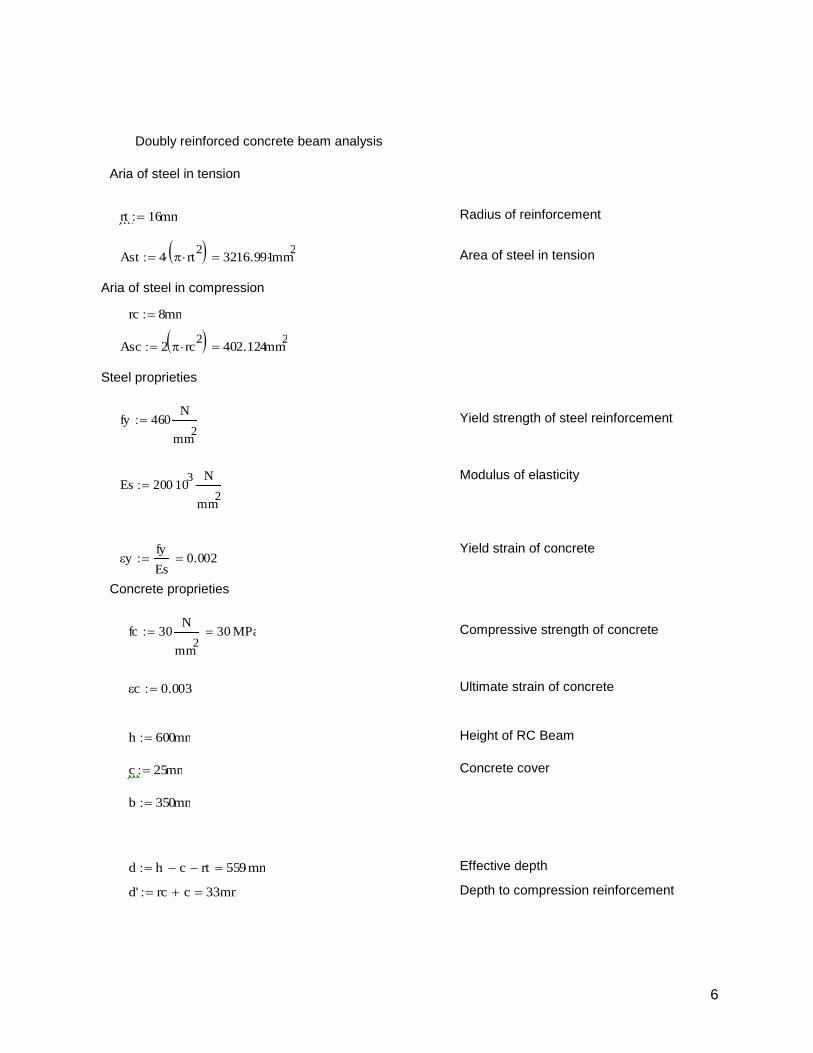
Doubly reinforced concrete beam analysis
Aria of steel in tension
Radius of reinforcement
Area of steel in tension
Aria of steel in compression
Steel proprieties
Yield strength of steel reinforcement
Modulus of elasticity
Yield strain of concrete
Concrete proprieties
Compressive strength of concrete
Ultimate strain of concrete
Height of RC Beam
Concrete cover
Effective depth
Depth to compression reinforcement
rt 16mm
Ast 4 rt2
3216.991mm2
rc 8mm
Asc 2 rc2
402.124mm2
fy 460N
mm2
Es 200 103
N
mm2
yfy
Es0.002
fc 30N
mm2
30 MPa
c 0.0035
h 600mm
c 25mm
b 350mm
d h c rt 559mm
d' rc c 33mm
7
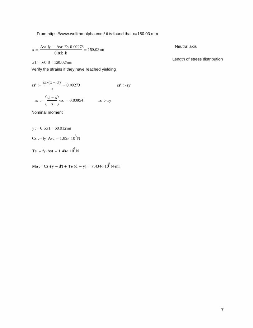
From https://www.wolframalpha.com/ it is found that x=150.03 mm
Neutral axis
Length of stress distribution
Verify the strains if they have reached yielding
Nominal moment
xAst fy Asc Es 0.00273
0.8fc b150.03mm
x1 x0.8 120.024mm
s'c x d'( )
x0.00273 s' y
sd x
x
c 0.00954 s y
y 0.5x1 60.012mm
Cs' fy Asc 1.85 105
N
Ts fy Ast 1.48 106
N
Mn Cs' y d'( ) Ts d y( ) 7.434 108
N mm
8
3 Appendix C
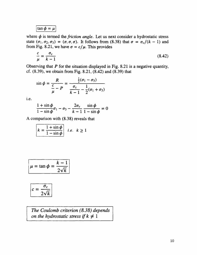
Mohr-Coulomb criterion the theory is taken from Niels Saabye Ottosen, Matti Ristinmaa. The
Mechanics of Constitutive Modelling. 2005.
Failure characteristics for concrete
We assume that 𝜎2 is of minor importance
The most simple expression of this form is then provided by a linear relation between the
principal stresses
Where k and m are material parameters. Requiring that this expression should predict the
uniaxial compressive strength value 𝜎𝑐, the stress state (𝜎1, 𝜎2, 𝜎3) = (0,0, −𝜎𝑐) should fulfil the
above equation and we find :

9
This so-called Coulomb criterion was suggested by Coulomb (1776) and is the oldest criterion
ever proposed.
Alternative formulation of the Coulomb criterion:
10

11

12
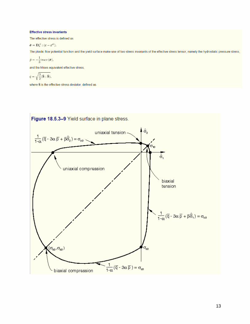
In order to further elucidate the properties of the Coulomb criterion, we consider its predictions
for plane stress conditions. From (8.38), the results shown in Fig. 8.25 are easily obtained
(note that in this figure the usual convention of 𝜎1 > 𝜎2 > 𝜎3 has been abandoned). It appears
that the predicted uniaxial tensile strength becomes 𝜎𝑡 = 𝜎𝑐/𝑘.
Due to its simplicity, the Coulomb criterion is widely used in analytical applications, cf. for instance
Chen (1975) for soil applications and Nielsen (1984) for concrete applications. In numerical
applications, however, its use is impeded by the comers of the surface, cf. Fig. 8.24. By
calibration of the parameter k, the criterion can be used to model a large variety of
materials.
Concrete damage plasticity
This part is taken from Dassault Systèmes. Abaqus Analysis User's Manual. 2013.
The concrete damaged plasticity model in Abaqus:
provides a general capability for modeling concrete and other quasi-brittle materials in all types of structures (beams, trusses, shells, and solids);
uses concepts of isotropic damaged elasticity in combination with isotropic tensile and compressive plasticity to represent the inelastic behavior of concrete;
can be used for plain concrete, even though it is intended primarily for the analysis of reinforced concrete structures;
can be used with rebar to model concrete reinforcement; is designed for applications in which concrete is subjected to monotonic, cyclic,
and/or dynamic loading under low confining pressures; consists of the combination of nonassociated multi-hardening plasticity and
scalar (isotropic) damaged elasticity to describe the irreversible damage that occurs during the fracturing process;
allows user control of stiffness recovery effects during cyclic load reversals; can be defined to be sensitive to the rate of straining; can be used in conjunction with a viscoplastic regularization of the constitutive
equations in Abaqus/Standard to improve the convergence rate in the softening regime;
13

14
Related Documents


