© 2015 - GZA GeoEnvironmental, Inc. T:\Clients\NorthernBCP\MXDs\April2015_Deliverable\Figure6_SSDS.mxd, 5/1/2015, 10:38:40 AM, patrick.finnerty NORTHTOWN PLAZA 3045 SHERIDAN DRIVE AMHERST, NEW YORK 14226 BK 1 in = 30 ft 31.0056687.30 MAY 2015 TGB JJR TGB PCF 6 FIGURE AOI 3 - SUB-SLAB DEPRESSURIZATION SYSTEMS REVISION NO. PROJECT NO. DATE: DESIGNED BY: PROJ MGR: DRAWN BY: REVIEWED BY: SCALE: CHECKED BY: PREPARED FOR: UNLESS SPECIFICALLY STATED BY WRITTEN AGREEMENT, THIS DRAWING IS THE SOLE PROPERTY OF GZA GEOENVIRONMENTAL, INC. (GZA). THE INFORMATION SHOWN ON THE DRAWING IS SOLELY FOR THE USE BY GZA'S CLIENT OR THE CLIENT'S DESIGNATED REPRESENTATIVE FOR THE SPECIFIC PROJECT AND LOCATION IDENTIFIED ON THE DRAWING. THE DRAWING SHALL NOT BE TRANSFERRED, REUSED, COPIED, OR ALTERED IN ANY MANNER FOR USE AT ANY OTHER LOCATION OR FOR ANY OTHER PURPOSE WITHOUT THE PRIOR WRITTEN CONSENT OF GZA, ANY TRANSFER, REUSE, OR MODIFICATION TO THE DRAWING BY THE CLIENT OR OTHERS, WITHOUT THE PRIOR WRITTEN EXPRESS CONSENT OF GZA, WILL BE AT THE USER'S SOLE RISK AND WITHOUT ANY RISK OR LIABILITY TO GZA. NORTHTOWN ASSOCIATES, LLC Legend: ! > B Sub-slab Soil Vapor & Indoor Air Sample Building Layout Installation Area For Sub-slab Depressurization Systems Approximate BCP Site Boundary - Includes AOI 3 Source: Erie County GIS Mapping Website Notes: All features should be considered approximate 0 30 60 15 SCALE IN FEET 4 PREPARED BY: GZA GeoEnvironmental, Inc. Engineers and Scientists www.gza.com

Welcome message from author
This document is posted to help you gain knowledge. Please leave a comment to let me know what you think about it! Share it to your friends and learn new things together.
Transcript
© 20
15 - G
ZA G
eoEn
viron
menta
l, Inc
. T:\C
lients
\Nort
hernB
CP\M
XDs\A
pril20
15_D
elive
rable\
Figure
6_SS
DS.m
xd, 5
/1/20
15, 1
0:38:4
0 AM,
patric
k.finn
erty
NORTHTOWN PLAZA3045 SHERIDAN DRIVE
AMHERST, NEW YORK 14226
BK1 in = 30 ft
31.0056687.30MAY 2015
TGBJJR TGB
PCF 6FIGURE
AOI 3 - SUB-SLAB DEPRESSURIZATIONSYSTEMS
REVISION NO.PROJECT NO.DATE:DESIGNED BY:PROJ MGR:
DRAWN BY:REVIEWED BY:
SCALE:CHECKED BY:
PREPARED FOR:
UNLESS SPECIFICALLY STATED BY WRITTEN AGREEMENT, THIS DRAWING IS THE SOLE PROPERTY OFGZA GEOENVIRONMENTAL, INC. (GZA). THE INFORMATION SHOWN ON THE DRAWING IS SOLELY FORTHE USE BY GZA'S CLIENT OR THE CLIENT'S DESIGNATED REPRESENTATIVE FOR THE SPECIFICPROJECT AND LOCATION IDENTIFIED ON THE DRAWING. THE DRAWING SHALL NOT BE TRANSFERRED,REUSED, COPIED, OR ALTERED IN ANY MANNER FOR USE AT ANY OTHER LOCATION OR FOR ANY OTHERPURPOSE WITHOUT THE PRIOR WRITTEN CONSENT OF GZA, ANY TRANSFER, REUSE, OR MODIFICATIONTO THE DRAWING BY THE CLIENT OR OTHERS, WITHOUT THE PRIOR WRITTEN EXPRESS CONSENT OFGZA, WILL BE AT THE USER'S SOLE RISK AND WITHOUT ANY RISK OR LIABILITY TO GZA.
NORTHTOWN ASSOCIATES, LLC
Legend:
!>BSub-slab Soil Vapor & Indoor AirSample
Building LayoutInstallation Area For Sub-slabDepressurization SystemsApproximate BCP Site Boundary -Includes AOI 3
Source: Erie County GIS MappingWebsiteNotes: All features should beconsidered approximate
0 30 6015SCALE IN FEET
4PREPARED BY:
GZA GeoEnvironmental, Inc.Engineers and Scientists
www.gza.com

APPENDIX A
SSDS Subcontractor Scope of Work

mitigation tech vapor intrusion specialists
April 30, 2015
Mr. James J. Richert P.G., C.P.G.Senior Project ManagerGZA GeoEnvironmental, Inc.535 Washington Street, 11th Floor | Buffalo, New York 14203Via email: James Richert <[email protected]>
Re: Northtown Plaza, Amherst NY - Soil Vapor Intrusion Mitigation System Proposal(2) south end units: Giro Cleaners and former Manhattan Bagel, and(1) unit in building to west
Dear Mr. Richert,
For you review and comment, we submit the following work plan:
1.0 Introduction
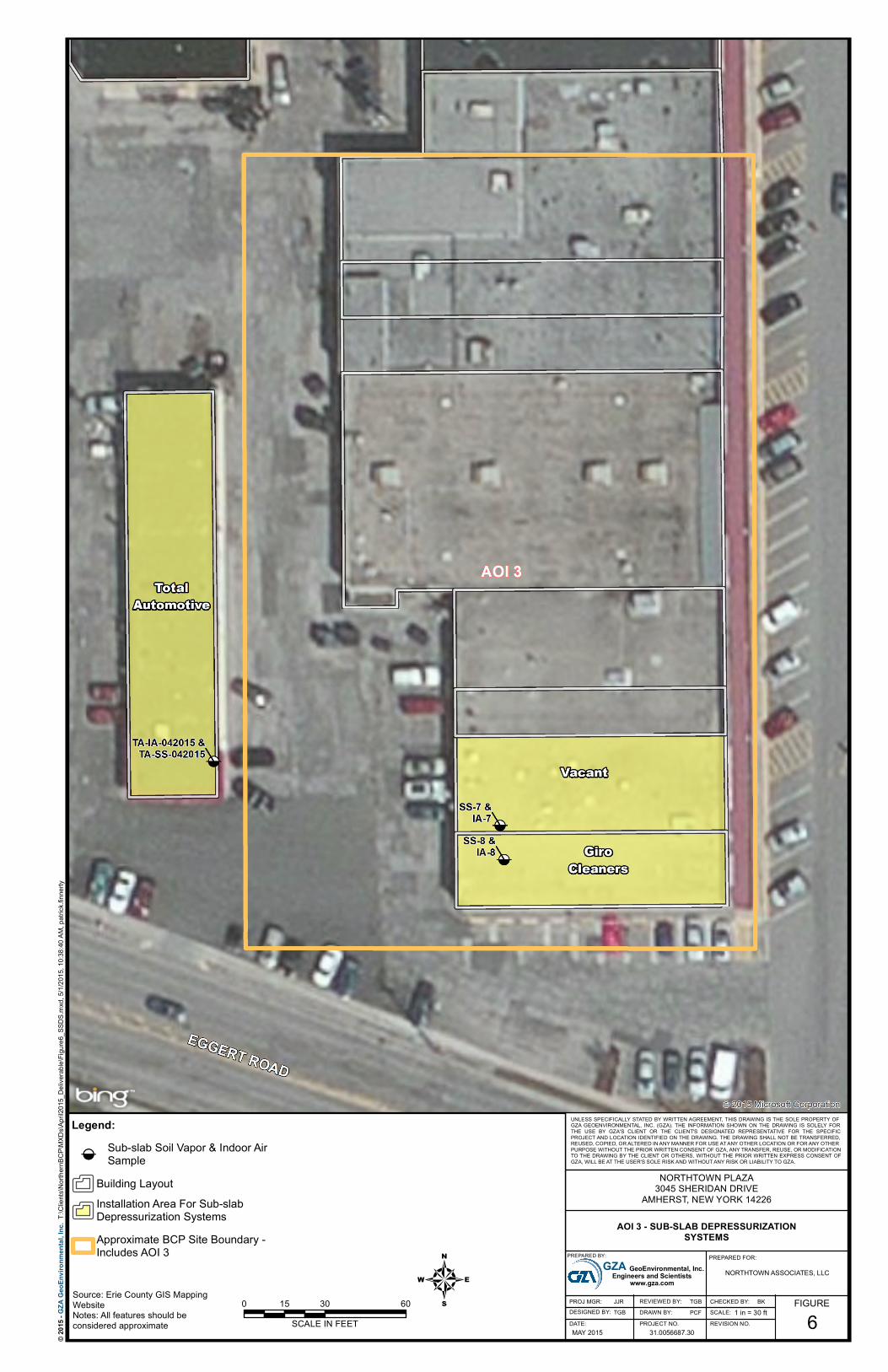
Soil vapor containing chlorinated volatile organic compounds has been detected at or near this site. Thisdocument presents a Work Plan that consists of the installation and operation of three sub-slab depressurizationsystems (SSDSs) that are designed to mitigate the migration or potential migration of sub surface vapors intothe building interiors. The subject areas are the foundation footprint of the two southernmost retail spaces,currently occupied by Giro Cleaners and formerly occupied by Manhattan Bagel and also the entirebuilding to the west that is currently occupied by Total Automotive Repair. The SSDSs are not intended toremove or diminish the source of the contamination. After start-up, demonstration of SSDS effectiveness will beconfirmed and thereafter, periodic maintenance and monitoring will be performed.
2.0 Objectives
This work plan was developed in general accordance with the NYS DOH document, “Guidance forEvaluating Soil Vapor Intrusion in the State of New York, October 2006”.
The objective of the SSDS is to create and maintain a minimum negative pressure differential of .004inches of water column (wci) below all concrete slabs which function as boundaries between sub-slabspace and occupied interior space. Once an SSDS has been installed, testing will be performed to verifythe extension of the pressure field. If and where necessary, additional measures will be furnished toensure that performance objectives are met. Modeling based on sub-slab air flow data suggests that theproposed design is sufficient.

April 30, 2015Page 2
- 2 -
3.0 Work Plan Design and Specifications
3.1 Overview
Work descriptions are based on certain assumptions identified herein and are subject to modificationbased on further field observations and measurements before and during construction.
3.2 Predesign Communication Testing
Sub-slab air communication testing would be performed before construction to verify design anddetermine the most efficient system configuration. The test procedure will include drilling core boringsand small diameter test holes to measure vacuum influence. Because of limited suction cavityplacement opportunities, testing would be directed toward designing a network of perimeter suctionpoints. Discovery of relatively dense sub-slab material may result in a higher number of suctioncavities or higher vacuum fans.
3.3 Scope of Work
The Scope of Work is to furnish and install (3) multi-point active sub-slab depressurization systems atthe designated locations. The Scope of Work is based on the construction necessary to achieve thedesign objective of furnishing a minimum .004 wci pressure differential at all areas of the sub -slab.
Furnish and Install: SYSTEM 1: Giro Cleaners System configuration - (1) RADONAWAY GP-501, roof mount over riser or manifold pipe, to
provide sub-slab depressurization via 3” schedule 40 PVC pipe to roof exhaust; w/ (3) suctionpoints along south perimeter wall and w/ (2) suction points along north perimeter wall
SYSTEM 2: former Manhattan Bagel System configuration - (1) RADONAWAY GP-501, roof mount over riser or manifold pipe, to
provide sub-slab depressurization via 3” schedule 40 PVC pipe to roof exhaust; w/ (2) suctionpoints along south perimeter wall and w/ (3) suction points along north perimeter wall
SYSTEM 3: Total Automotive Repair System configuration - (1) RADONAWAY GP-501, roof mount over riser or manifold pipe, to
provide sub-slab depressurization via 3” schedule 40 PVC pipe to roof exhaust; w/ (4-5)suction points along south perimeter wall or as determined
COMMON ELEMENTS: Pre-construction consultation to obtain approval for component placements Suction points as follows: connection via 3” Schedule 40 PVC pipe, to cavity in sub-slab, with
urethane seal; access hole to suction cavity by 5”core drill or hand drill; suction cavity toconsist of approximately 1 cu. ft. excavated material in sub-slab
Electrical switch at fan with Sealtite conduit to building interior; final connection to panel byothers at other’s expense
Roof flashing for pipe penetrations; extra cost if roof warranty requires work by originalcontractor
Proportioning valves or plates for suction risers where required All exhaust points minimum 10” from any air intakes Exterior switch and Sealtight and/or MC conduit from fan housings to vicinity of electrical
panel; final connection to circuit or panel in vicinity of fans (2) U-tube style vacuum indicator per system, on vertical pipe run; location TBD

April 30, 2015Page 3
- 3 -
Urethane sealant at slab joints, accessible cracks and penetrations in vicinity of suction points Horizontal pipe near ceiling, with metal bracketing direct to structure, sloped as required,
above drop ceiling where present At completion, perform backdraft testing, measure pressure differentials and document; label
components and provide system description and operational instructions Permits and inspections at additional cost Consult with client engineering representatives to develop operation, maintenance and
periodic inspection plan Two year warranty; labor and installed components
3.4 Post Installation Pressure Field Extension Testing
A digital micromanometer will be used to measure pressure differentials and values will be recorded ona floor plan. All test holes will be repaired with urethane caulk (MSDS available) applied over a closedcell backer rod. Smoke tubes will be used to identify floor cracks and other openings to the sub-slabthat could “short circuit” the pressure field. Backdrafting testing will be performed.
3.5 System Operation Following Power Loss
The systems will restart automatically after power restoration.
3.6 General Work Plan Provisions Daily tailgate meeting for safety review Hazwoper trained personnel to perform drilling operations PID monitoring not included Level 4 PPE for on-site personnel Procedures to follow site specific HASP
3.7 IRM Construction Completion Report
At conclusion of construction, a Construction Completion Report (CCR) will be submitted.This report will include an as-built drawing, showing SSDS locations and components. TheCCR will include measurements of created sub-slab to ambient air static pressure differentials,detailed descriptions of SSDS components, and post-installation sampling results.
An Operations, Maintenance, and Monitoring (OM&M) Plan will be submitted with the CCR. TheOM&M Plan will be provided to the owner and occupants to facilitate their understanding of thesystem's operation, maintenance and monitoring. The OM&M Plan will include the following:
a description of the SSDS Installed and its basic operating principles, with diagram; how the owner or tenant can check that the SSDS is operating properly; how the SSDS will be maintained and monitored and by whom; a description of long-term reporting and annual SSDS certification requirements; a list of appropriate actions for the owner or tenant to take if a SSDS warning device
(manometer) indicates system degradation or failure; a description of the proper operating procedures for the SSDS, including manufacturer's
operation and maintenance instructions and warrantees; and contact information if the owner or tenant has questions, comments, or concerns.

April 30, 2015Page 4
- 4 -
3.8 Maintenance and Monitoring
Future monitoring will be proposed to monitor system communication via differential pressuremeasurements. The monitoring will be performed annually until a less-frequent monitoringfrequency is approved. This routine monitoring will include:
visual inspection of the equipment and piping; inspection of exhaust points to verify that no air intakes have been located nearby; identification and subsequent repair of any leaks; audible operational status check of vent fans; damper adjustments as required to balance parallel branches of system; measurement of differential pressure between the indoor air and the sub-slab to ensure a
lower pressure is being maintained in the sub-slab relative to indoor ambient, as indicatedby the pressure gauge on the fan suction pipe.
The SSDS will be operated until such time as permission in writing is received from NYSDEC toterminate operation of the system and remove the equipment.
3.9 Schedule
Client shall provide notification to tenants for timing of construction and shall obtain any necessaryaccess agreements.
It is anticipated that work can be completed within thirty days of receipt of order. It is anticipatedthat portions of the work involving considerable noise or intrusion will take place after hours.
3.10 Discharge Permitting
It is understood that an air discharge permit to discharge treated vapors will not be required. It isfurther understood that all discharges will be direct to the atmosphere and that a Community AirMonitoring Plan is not required.
4.0 Cost: To be provided under separate cover
END OF WORK PLAN
Thank you.
Nicholas E. Mouganis EPA listing # 15415-I; NEHA ID# 100722
55 SHUMWAY ROAD, BROCKPORT, NEW YORK, 14420 * OFFICE/FAX 585-637-7430
APPENDIX B
Quality Assurance Project Plan

QUALITY ASSURANCEPROJECT PLANNORTHTOWN INC.AMHERST, NEW YORKBROWNFIELD CLEANUP PROGRAMSITE NO. C915292
Prepared For:New York State Department of Environmental ConservationRegion 9Buffalo, New York
Prepared By:GZA GeoEnvironmental of New YorkBuffalo, New York
May 2015File No: 31.0056687.30
Copyright© 2015 GZA GeoEnvironmental of New York
May 1, 2015Page i
QUALITY ASSURANCE PROJECT PLANNORTHTOWN INC.
ELLICOTTVILLE, NEW YORKBROWNFIELD CLEANUP PROGRAM
SITE NO. C915292
TABLE OF CONTENTSPage
1.0 INTRODUCTION .................................................................................................................. 1
1.1 PURPOSE AND OBJECTIVE........................................................................................... 11.2 PROJECT BACKGROUND .............................................................................................. 11.3 PROJECT DESCRIPTION................................................................................................. 31.4 PROJECT MANAGEMENT AND ORGANIZATION ..................................................... 3
1.4.1 Personnel..................................................................................................................... 31.4.2 Specific Tasks and Services........................................................................................ 4
2.0 SITE INVESTIGATION PROCEDURES AND RATIONALE............................................ 4
2.1 AIR SURVEILLANCE AND MONITORING................................................................... 42.2 SOIL SAMPLING .............................................................................................................. 42.3 EQUIPMENT DECONTAMINATION ............................................................................. 5
2.3.1 Non-Dedicated Reusable Equipment.......................................................................... 52.3.2 Disposable Sampling Equipment................................................................................ 62.3.3 Heavy Equipment........................................................................................................ 6
2.4 STORAGE AND DISPOSAL OF INVESTIGATION-DERIVED WASTE...................... 6
3.0 SAMPLE HANDLING........................................................................................................... 7
3.1 SAMPLE IDENTIFICATION/LABELING....................................................................... 73.2 SAMPLE, BOTTLES, PRESERVATION, AND HOLDING TIME.................................. 7
3.2.1 Sample Bottles ............................................................................................................ 73.2.2 Holding Times ............................................................................................................ 8
3.3 CHAIN OF CUSTODY AND SHIPPING .......................................................................... 8
4.0 QUALITY ASSURANCE/QUALITY CONTROL PROTOCOLS....................................... 9
4.1 ANALYTICAL METHODS, PROCEDURES & CALIBRATION ................................... 94.1.1 Methods....................................................................................................................... 94.1.2 Laboratory Instrumentation & Equipment.................................................................. 94.1.3 Field Equipment.......................................................................................................... 9
4.2 QUALITY CONTROL SAMPLES .................................................................................. 104.2.1 Analytical Equipment ............................................................................................... 104.2.2 Field Samples............................................................................................................ 10
5.0 DATA DOCUMENTATION ............................................................................................... 11
5.1 FIELD NOTEBOOK ........................................................................................................ 115.2 FIELD REPORTING FORMS........................................................................................... 11

May 1, 2015Page ii
TABLE OF CONTENTS (continued)Page
6.0 CORRECTIVE ACTIONS ................................................................................................... 11
7.0 DATA REDUCTION, VALIDATION, AND REPORTING .............................................. 12
7.1 LABORATORY DATA REPORTING AND REDUCTION........................................... 127.2 DATA VALIDATION...................................................................................................... 137.3 FIELD DATA ................................................................................................................... 13
8.0 PERFORMANCE AND SYSTEM AUDITS....................................................................... 13
9.0 QUALITY ASSURANCE REPORTS TO MANAGEMENT ............................................. 14
LIST OF TABLES
Table 1 Summary of Container, Preservation and Holding Time Requirements
LIST OF FIGURES
Figure 1 Locus Map
Figure 2 Site Plan
May 1, 2015Page 1
1.0 INTRODUCTION
1.1 PURPOSE AND OBJECTIVE
This Quality Assurance Project Plan (QAPP) has been developed by GZA GeoEnvironmental ofNew York (GZA) for project activities associated with the Northtown Inc. Brownfield CleanupProgram (BCP) Site No. C915292 located at 3097 Sheridan Drive, Amherst, New York (see Figure1). This QAPP presents the project scope, objectives, organization, planned activities, samplingprocedures, data quality objectives and quality assurance/quality control (QA/QC) procedures.
Protocols for sample collection, sample handling and storage, equipment decontamination, chain-of-custody procedures, etc. are described in Section 3. This QAPP was developed in generalaccordance with the requirements of Section 2.4 of the NYSDEC DER-10/Technical Guidance forSite Investigation and Remediation, effective May 3, 2010 (NYSDEC DER-10).
1.2 PROJECT BACKGROUND
The BCP Site consists of three AOIs collectively comprising approximately 1.5 acres of anapproximately 18.6 acre parcel of land on which the Northtown Plaza is located. Currently thePlaza property is occupied by six commercial buildings, most containing multiple tenant spaces.The Site is bordered by other areas of the Northtown Shopping Plaza and beyond that SheridanDrive to the North, Eggert Road to the south, Bailey Avenue to the east and Niagara FallsBoulevard to the west. Northtown Shopping Plaza is located in a commercial business area alongSheridan Drive and Niagara Falls Boulevard. The primary use of the area is as a shopping district,with major retailers located within a ½ mile of the Site. Residential properties are located on theside streets surrounding the site. Figure 2 presents a site plan.
The Site appears to have been agricultural land until it was developed for commercial use in theearly-1950s. Site development occurred from the mid-1950s to 1983 when it reached site usagesimilar to today. Site occupant uses of environmental concern have included a dry cleaner. On-sitedry cleaning operations ceased at the Site in the 1990s but there currently is an active pick-up/drop-off dry cleaning business in the same location (cleaning operation is performed at an off-sitefacility).
No underground storage tanks (USTs) are currently being used at the Site or other portions ofNorthtown Plaza. However, two USTs formerly used for heating oil remain at the Site.
A Phase I Environmental Site Assessment completed by GZA for the entire Northtown Plazaproperty in accordance with ASTM 1527 identified Recognized Environmental Conditions (RECs)including the former use of USTs (see above) and the former on-site dry cleaning operations at theSite.
A Phase II Environmental Site Assessment was completed by GZA to assess the RECs identifiedin the Phase I. The assessment included the following:
May 1, 2015Page 2
The completion of 51 soil probes and the installation of 3 groundwater monitoring
wells;
The analyses of 53 soil samples for Target Compound List (TCL) Volatile Organic
Compounds (VOCs) EPA Method 8260, Spill Technology and Remediation Series
(STARS) Semi-Volatile Organic Compounds (SVOCS) EPA Method 8270, and Poly
Chlorinated Biphenyl’s (PCBs) EPA Method 8082;
The analyses of three groundwater samples for TCL VOCs EPA Method 8260;
Indoor air and sub-slab soil vapor sampling at three tenant spaces;
A camera survey of sewer lines associated with the dry cleaning unit; and
A Ground Penetrating Radar (GPR) study of known current and past UST locations.
Soil impacts were detected at three discreet locations: proximate to the two abandoned fuel oilUSTs locations, and in the vicinity of the dry cleaners unit. No VOCs were detected above theNYSDEC Class GA Criteria in groundwater collected from the three deep overburden monitoringwells completed at the Site.
Limited areas of visual and olfactory evidence of petroleum were encountered in the vicinity ofthe southern (AOI1) and western (AOI2) inactive heating oil USTs. NYSDEC was notified onMay 9, 2014 and spill number 1401409 was assigned for both USTs. The extent of the impactdetected in the UST areas are immediately adjacent to the USTs and limited to the uppermost 6 to8 feet. Approximately 20 soil probes were completed on the west side of the dry cleaner’s space(AOI3). Fifty three soil samples were analyzed for VOCs. PCE was detected above theUnrestricted Soil Cleanup Objectives (USCO) in 16 soil samples, above the Commercials SoilCleanup Objectives (CSCO) in two samples, and above the Industrial Soil Cleanup Objectives(ISCO) in one sample. The PCE impacts were restricted to a depth between 6 and 18 feet belowground surface. No surficial soil impacts were identified.
One deep monitoring well was installed in the area of the PCE soil impacts and two other locationsdid not show impacts to the groundwater in this area. Groundwater was encountered atapproximately 50 feet below ground surface.
To further characterize AOI3, GZA completed a Pre-Design Field Characterization (PDFC) inMarch and April of 2015. Twenty five additional soil probes were advanced using direct pushdrilling methods. Eighteen of these soil probes were located at exterior areas of AOI 3, and 7 werelocated within the vacant tenant space #13, which is directly north and adjacent to the dry cleanerspace. GZA installed six, 1-inch diameter, shallow water monitoring wells at six of the soil probelocations.
Based on the results of the Phase II and PDFC, four areas of PCE impacted subsurface soil wereidentified at the western exterior of AOI3. The four samples that exceeded CSCOs for PCE are SP-
May 1, 2015Page 3
23, SP-47, SP-56, and SP-62 and the extent of impact at each of these areas is of limited extent. Theimpacted depth intervals in exceedance of the CSCOs range from six feet at SP-47 to seventeen feetSP-62. Soil samples collected from probes surrounding the four data points contained PCE atconcentrations below the CSCO, illustrating the limited extent of the higher concentrations of PCE.
1.3 PROJECT DESCRIPTION
This QAPP is the quality control basis for the scope of work, which is further described in theInterim Remedial Measures Work Plan. The major tasks involved at the Site are:
Interim Remedial Measures Work Plan Development (Field Activity Plan,Health and Safety Plan, and Quality Assurance Project Plan).
Implementation of an Interim Remedial Measure Revision of the Alternatives Analysis Report
1.4 PROJECT MANAGEMENT AND ORGANIZATION
1.4.1 Personnel
The general responsibilities of key project personnel are listed below.
NYSDEC Project Manager – Tim Dieffenbach will have the responsibility for regulatoryoversight for the work associated with BCP Site No. C915292.
Northtown Associates LLC Project Manager – Andrew Manning will have theresponsibility for implementing the project and has the authority to commit fundingnecessary to meet the objectives and requirements.
GZA Project Manager – Jim Richert will be responsible for managing the implementationof the activities associated with the BCP investigation, remediation and coordinating thecollection of data during the project. The Project Manager is responsible for technicalquality control and project oversight.
Quality Assurance (QA) Officer – Todd Bown will report to the Project Manager and willbe responsible for ensuring that QA/QC procedures are being followed. The QA Officerwill be responsible for overseeing the review of field and laboratory data.
The QA Officer will monitor the performance of the laboratory to verify that the DataQuality Objectives for the project are met.
Field QA Officer – Todd Bown will be responsible for the overall operation of the fieldteam and reports directly to the Project Manager.

May 1, 2015Page 4
1.4.2 Specific Tasks and Services
GZA will obtain subcontractor specialists for services relating to underground storage tankremoval, soil excavation, soil transport and disposal, sub-slab vapor mitigation systemdesign and installation, laboratory/analytical services and data validation services. Thesubcontractors to be utilized will be determined at a later time.
2.0 SITE INVESTIGATION PROCEDURES AND RATIONALE
AOI 1 and AOI 2 of the BCP Site each contain one inactive underground storage tank (UST) thatwere reportedly used to store fuel oil. Petroleum impacted soil is present adjacent to each UST.At AOI 3, chlorinated solvent impacts are present in the overburden soil and shallow pore waterof the overburden. The IRM fieldwork proposed by GZA is the result of extensive sitecharacterization work and focuses mainly on removal of the USTs and impacted soils as well andinstallation of sub-slab depressurization of two tenant units at AOI 3 and one space to the west ofAOI3. Environmental sampling will be performed in conjunction with the removal actions for thefollowing purposes:
confirmation sampling of excavation sidewalls and bottom; characterization of “clean” backfill materials; and characterization of soil and waters (if present) for disposal purposes.
Environmental sampling and other field activities will be performed in general accordance withthe NYSDEC DER-10 guidance document.
General field activities are described in the following sections and described in further detail in theInterim Remedial Measures Work Plan.
2.1 AIR SURVEILLANCE AND MONITORING
Air surveillance screening for total volatile organics and particulates for health and safety concernswill be performed with a portable organic vapor meter (OVM) equipped with a photoionizationdetector (PID) that is using a 11.7 electron volt (eV) bulb and dust monitors placed both upwindand downwind of intrusive work sites. Monitoring will be performed during invasive activitiessuch as soil excavation and UST removal. The OVM will also be used to field screen samples.Additional details are presented in the Site-specific Health and Safety Plan which includes theNYSDOH generic Community Air Monitoring Plan (CAMP).
2.2 SOIL SAMPLING
Soil sampling will occur during remedial activities involving excavation and removal of impactedsoil and USTs, confirmatory sampling and waste characterization. Samples will be collected andtransferred to sample containers as soon as possible after being retrieved from the subsurface (i.e.,excavator bucket).
May 1, 2015Page 5
The excavator will be decontaminated by the subcontractor prior to arrival on-Site. Duringremedial activities, decontamination will be accomplished using steam cleaning or high pressurehot water to wash equipment prior to moving to the next location. Stainless steel sampling deviceswill be cleaned manually with non-phosphate detergent (i.e., alconox) wash and potable waterfollowed by a potable water rinse or a second steam cleaning followed by a distilled/deionizedwater rinse. Equipment will be similarly cleaned prior to leaving the Site.
Soil samples, with the exception of those for VOCs, will be homogenized using a "coning andquartering" procedure. The soil will be removed from the sampling equipment and transferred toa clean surface (metal foil, steel pan, bowl, etc.). Observed debris, such as bricks, large stones,organics, etc. will be removed from the sample. The soil will be mixed to provide a morehomogeneous sample for lab analysis. The soil will be scraped from the sides, corners, and bottomof the clean surface, rolled to the middle, and thoroughly mixed until the material appearshomogenous. An aliquot of this pile will then be transferred to the required sample containers,slightly tamped-down, filled to near the top of the container, and sealed with the appropriate cap.Soil or sediment on the threads of the container will be removed prior to placing the cap on thesample container. Soil samples for VOC analysis will be collected and directly placed into oneunpreserved 2 oz jar per sample location.
Soil screening will be performed in two ways: by holding the probe of the OVM directly over thesample once it is retrieved from the subsurface and again by headspace screening after arepresentative portion of the soil samples has been placed in plastic bags, allowed to warm toambient temperature, and placing the tip of the OVM into the plastic bag. The OVM used will beequipped with a PID that is using a 11.7 eV bulb.
The OVM will be calibrated daily, in accordance to manufacturer's requirements using a standardgas. Prior to screening, the headspace soil samples will be allowed to equilibrate to ambienttemperature. For headspace screening, a hole will be made in the sample bag and the tip of theOVM inserted into the bag, and the peak response will be recorded. A response of less than 1 partper million (ppm), using this method, is not considered significant and will be reported as notdetected. A blank will be run between test samples to check that extraneous contamination wasnot carried over.
2.3 EQUIPMENT DECONTAMINATION
To avoid cross contamination, non-disposable sampling equipment (defined as any piece of re-usable equipment which may contact a sample) will be decontaminated according to the followingprocedures outlined below.
2.3.1 Non-Dedicated Reusable Equipment
Non-dedicated reusable equipment such as stainless steel mixing bowls; pumps used forgroundwater evacuation (and sampling, if applicable) etc. will require field decontamination.Acids and solvents will not be used in the field decontamination of such equipment.

May 1, 2015Page 6
Decontamination typically involves scrubbing/washing with a laboratory grade detergent (e.g.alconox) to remove visible contamination, followed by potable (tap) water and analyte-free waterrinses. Tap water may be used from any treated municipal water system; the use of an untreatedpotable water supply is not an acceptable substitute. Equipment should be allowed to dry prior touse. Steam cleaning or high pressure hot water cleaning may be used in the initial removal ofgross, visible contamination. Tubing will not be re-used (new tubing will be used for each well).
2.3.2 Disposable Sampling Equipment
Disposable sampling equipment will not be field-decontaminated; equipment may berinsed with laboratory-provided analyte-free water prior to use. Disposable spoons or spatulaspurchased from non-environmental equipment vendors (such as restaurant supply houses) will bedecontaminated by scrubbing/washing with a laboratory grade detergent followed by potable waterand Analyte-free water rinse; or by using steam or high pressure hot water rinse, followed byanalyte free water rinse. The equipment will be allowed to air dry prior to use.
2.3.3 Heavy Equipment
Certain heavy equipment such as, excavator buckets, etc. may be used to obtain samples.Such equipment will be subject to high pressure hot water or steam cleaning between uses. Amember of the sampling team will visually inspect the equipment to check that visiblecontamination has been removed by this procedure prior to sampling. Such equipment will becleaned between excavation locations. Decontamination between excavation samples at a singlelocation will be performed using alconox and water to clean the samplers. Samples submitted foranalysis will not include material, which has been in direct contact with the excavator bucket.
2.4 STORAGE AND DISPOSAL OF INVESTIGATION-DERIVED WASTE
The sampling methods and equipment have been selected to limit both the need fordecontamination and the volume of waste material to be generated. Investigation-derived material(e.g., decon sediments and water) generated during this project shall be presumed to be non-hazardous waste and will be characterized for off-site disposal at a permitted and NYSDEC-approved waste disposal facility.
Personal protective equipment and disposable sampling equipment will be placed in plasticgarbage bags for disposal as a non-hazardous solid waste.
Decontamination Fluids
Wash water and rinse water, including detergent, may be generated during Site work. Non-phosphate detergent and water rinse will be disposed off-Site along with water generated fromexcavations if present.
May 1, 2015Page 7
3.0 SAMPLE HANDLING
3.1 SAMPLE IDENTIFICATION/LABELING
Samples will be assigned a unique identification using the sample location or other sample-specificidentifier. Sample identification will be limited to seven alphanumeric characters to be consistentwith the limitations of the laboratory tracking/reporting software. The general sampleidentification format follows.
SW - XX - Y-YWhere:
SW = Type of sample (i.e., Side Wall, Excavation Bottom)XX = Numeric character indicating the number from which the
sample was obtained.Y-Y = Depth of the sample.
Quality control (QC) field duplicate samples will be submitted blind to the laboratory; a fictitioussample identification will be created using the same system as the original. The sampleidentifications (of the original sample and its field duplicate) will be marked in the project specificfield book and on the copy of the chain-of-custody kept by the sampler and copied to the projectmanager. Sample containers will be labeled in the field prior to the collection of samples. Affixedto each sampling container will be a non-removable label on which the following information willbe recorded with permanent water-proof ink:
Site name and location; Sample identification code; Date and time; Sampler's initials; Preservative; and Requested analyses.
3.2 SAMPLES, BOTTLES, PRESERVATION, AND HOLDING TIME
Table 1 specifies the analytical method, matrix, holding time, containers, and preservatives for thevarious analyses to be completed. Sample bottle requirements and holding times are discussedfurther below.
3.2.1 Sample Bottles
The selection of sample containers used to collect samples is based on the criteria of samplematrix, analytical method, potential contaminants of concern, reactivity of container material withthe sample, QA/QC requirements and regulatory protocol requirements. Sample bottles will beprovided by the analytical laboratory and will conform to the requirements of USEPA'sSpecifications and Guidance for Contaminant-Free sample Containers.
May 1, 2015Page 8
3.2.2 Holding Times
Holding times are judged from the verified time of sample receipt (VTSR) by thelaboratory; samples will be shipped from the field to arrive at the lab no later than 48 hours fromthe time of sample collection. Holding time requirements will be those specified in the NYSDECASP; it should be noted that for some analyses, these holding times are more stringent than theholding time for the corresponding USEPA method.
Although trip blanks are prepared in the analytical laboratory and shipped to the Site priorto the collection of environmental samples, for the purposes of determining holding timeconformance, trip blanks will be considered to have been generated on the same day as theenvironmental samples with which they are shipped and delivered. Procurement of bottles andblanks will be scheduled to prevent trip blanks from being stored for excessive periods prior totheir return to the laboratory; the goal is that trip blanks should be held for no longer than one weekprior to use.
3.3 CHAIN OF CUSTODY AND SHIPPING
A chain-of-custody form will trace the path of sample containers from the project site to thelaboratory. A sample Chain of Custody is included in Attachment 1, Field Forms. Sample/bottletracking sheets or the chain-of-custody will be used to track the containers from the laboratory tothe containers' destination. The project manager will notify the laboratory of upcoming fieldsampling events and the subsequent transfer of samples. This notification will include informationconcerning the number and type of samples, and the anticipated date of arrival. Insulated sampleshipping containers (typically coolers) will be provided by the laboratory for shipping samples.All sample bottles within each shipping container will be individually labeled with an adhesiveidentification label provided by the laboratory. Project personnel receiving the sample containersfrom the laboratory will check each cooler for the condition and integrity of the bottles prior tofield work.
Once the sample containers are filled, they will be immediately placed in the cooler with ice (inplastic bags to prevent leaking) or synthetic ice packs to maintain the samples at 4 oC. The fieldsampler will indicate the sample designation/location number in the space provided on the chain-of-custody form for each sample. The chain of custody forms will be signed and placed in a sealedplastic bag in the cooler. The completed shipping container will be closed for transport with nylonstrapping, or a similar shipping tape, and two paper seals will be affixed to the lid. The seals mustbe broken to open the cooler and will indicate tampering if the seals are broken before receipt atthe laboratory. The cooler will be shipped either by laboratory-provided courier or by an overnightdelivery service to the laboratory. When the laboratory receives the coolers, the custody seals willbe checked and lab personnel will sign the chain-of-custody form.

May 1, 2015Page 9
4.0 QUALITY ASSURANCE/QUALITY CONTROL PROTOCOLS
This section describes the analytical methods, principles and procedures that will be used togenerate quality data. These protocols include laboratory calibration, field equipment calibration,QC sample collection and analysis, quantitative evaluation of data quality protocols and dataqualification, if necessary.
4.1 ANALYTICAL METHODS, PROCEDURES & CALIBRATION
4.1.1 Methods
Analytical methods to be used during this project are presented in the NYSDEC AnalyticalServices Protocol (ASP), June 2005. Specific methods and references for each parameter areshown in Table 1. The sample preservation and holding time requirements are also identified inTable 1. Quantification and detections limits for all analysis are those specified under theappropriate test methods.
It is the laboratory's responsibility to be familiar with this document, procedures anddeliverables pertaining to the Site work. Alpha Analytical is tentatively scheduled to perform theanalytical testing. Alpha is certified by the NYSDOH Environmental Laboratory ApprovalProgram and Contract Laboratory Protocol certified.
4.1.2 Laboratory Instrumentation & Equipment
Laboratory instruments and equipment will be calibrated following SW-846 analyticalmethods protocol. Initial calibrations will be performed before samples analysis. Calibrationchecks will be performed at the frequencies specified in each analytical method.
4.1.3 Field Equipment
Field equipment will be used during various activities of the project and during thecollection of environmental samples. The field equipment to be used may include the following.
Field equipment used includes:
OVM with a photoionization detector. Electronic water level indicator. Multi-gas meter (CO, LEL, O2, and H2S). Particulate monitor
Field equipment will be cleaned and calibrated prior to use. The Operating andMaintenance (O&M) manuals for the field equipment will be kept in the field when in use and acopy will be retained in project files.

May 1, 2015Page 10
Calibration and standardization for the field equipment during project use will be inaccordance with the manufacturer’s recommendations, and will be recorded in the field log book.If instrument performance or data fall outside acceptable limits, then corrective actions will betaken. These actions may include recalibration of instruments, acquiring new standards, replacingequipment or repairing equipment. Subcontractors providing analytical services should performtheir own internal laboratory audits and calibration procedures with data review conducted at afrequency so that errors and problems are detected early, thus avoiding the prospect of redoinglarge segments of work.
4.2 QUALITY CONTROL SAMPLES
4.2.1 Analytical Equipment
The analytical methods to be utilized (see Table 1) for laboratory sample analysis addressthe quality control to be used and the frequency of replicates, blanks and calibration standards forlaboratory analytical equipment.
4.2.2 Field Samples
Field quality control samples will consist of trip blanks, sample duplicate, matrix spike andmatrix spike duplicate. Trip blanks, for VOCs only, will consist of analyte free reagent gradewater in VOC sampling containers to be used for the project. Trip blanks will be prepared at thelaboratory, sealed, transported to the Site and returned without being opened to assesscontamination that may have occurred during transport. Trip blanks will be submitted at a rate ofone per sampling event when VOCs are shipped to the laboratory.
Field duplicate samples are used to assess the variability of a matrix at a specific samplingpoint and to assess the reproducibility of the sampling method. For soil samples, these samplesare separate aliquots of the same sample; prior to dividing the sample into "sample" and "duplicate"aliquots, the samples are homogenized (except for the VOC aliquots, which are not homogenized).Aqueous field duplicate samples are second samples collected from the same location, at the sametime, in the same manner as the first, and placed into a separate container. Each duplicate samplewill be analyzed for the same parameters as the original sample collected that day. The blind fieldduplicate Relative Percent Difference (RPD) objective will be +50% percent RPD for all matrices.Field duplicates will be collected at a frequency of 1 per 20 environmental samples for bothmatrices (aqueous and non-aqueous) and test parameters.
Matrix spike/matrix spike duplicate (MS/MSD) samples are used to assess the laboratorymethod’s accuracy and precision. These samples are spiked with known quantities of targetanalytes at the laboratory. The samples are collected at a frequency of five percent(1 in 20).
May 1, 2015Page 11
5.0 DATA DOCUMENTATION
5.1 FIELD NOTEBOOK
Field notebooks will be initiated at the start of on-Site work, in addition to field forms that will befilled out summarizing field work and become part of the project file. The field notebook willinclude the following daily information for Site activities:
Date; Meteorological conditions (temperature, wind, precipitation); Site conditions (e.g., dry, damp, dusty, etc.); Identification of crew members (GZA and subcontractor present) and other personnel (e.g.,
agency or site owner) present; Description of field activities; Location(s) where work is performed; Problems encountered and corrective actions taken; Records of field measurements or descriptions recorded; and, Notice of modifications to the scope of work.
5.2 FIELD REPORTING FORMS
Field reporting forms (or their equivalent) to be utilized during the remediation may include thefollowing:
Excavation Log; Sample Collection Log; Chain of Custody Form; and Calibration Log.
These forms, when completed, will become part of the project file.
6.0 CORRECTIVE ACTIONS
If instrument performance or data fall outside acceptable limits, then corrective actions will betaken. These actions may include recalibration or standardization of instruments, acquiring newstandards, replacing equipment, repairing equipment, and reanalyzing samples or redoing sectionsof work. Subcontractors providing analytical services should perform their own internal laboratoryaudits and calibration procedures with data review conducted at a frequency so that errors andproblems are detected early, thus avoiding the prospect of redoing large segments of work.

May 1, 2015Page 12
Situations related to this project requiring corrective action will be documented and made part ofthe project file. For each measurement system identified requiring corrective action, theresponsible individual for initiating the corrective action and also the individual responsible forapproving the corrective action, if necessary, will be identified. As part of its total qualitymanagement program, GZA makes the results of laboratory audits and data validation reportsavailable to the analytical laboratories. The laboratories are therefore made aware of non-criticalitems and areas where improvement may be made in subsequent NYSDEC ASP work.
7.0 DATA REDUCTION, VALIDATION, AND REPORTING
The guidance followed to perform quality data validation, and the methods and proceduresoutlined herein pertain to initiating and performing data validation, as well as reviewing datavalidation performed by others (if applicable). An outline of the data validation process ispresented here, followed by a description of data validation review summaries.
7.1 LABORATORY DATA REPORTING AND REDUCTION
The laboratory will meet the applicable documentation, data reduction, and reporting protocols asspecified in the 2005 revision of the NYSDEC ASP CLP. Laboratory data reports for non-CLPdata will conform to NYSDEC Category B deliverable requirements. With full CLPdocumentation, deliverables will include, but not be limited to:
Organics Inorganics
Chains of Custody Chains of CustodyBlanks BlanksHolding Times Holding TimesInternal Standards Furnace AA QCLaboratory Duplicates CRDL StandardsTentatively Identified Compounds ICP Serial DilutionsGC/MS Instrument Performance Check Laboratory Control SamplesSystem Monitoring Compound Recovery Laboratory DuplicatesMatrix Spike & Matrix Spike Duplicates ICP Interference CheckGC/MS Tuning Spiked Sample RecoverySurrogate Recoveries
Copies of the laboratory's generic Quality Assurance Plan (QAP) will be on file at GZA. Thelaboratory's QAP will indicate the standard methods and practices for obtaining and assessing data,and how data are reduced from the analytical instruments to a finished report, indicating levels ofreview along the way.

May 1, 2015Page 13
In addition to the hard copy of the data report, the laboratory will be asked to provide the sampledata in spreadsheet form to minimize possible transcription errors resulting from the manualtranscription of data.
7.2 DATA VALIDATION AND DATA USABILITY SUMMARY REPORT
CLP data will be validated by a data validation subcontractor. Data validation will be performedin accordance with guidelines established in Appendix 2B of the NYSDEC DER-10. Wherenecessary and appropriate, supplemental validation criteria may be derived from the EPAFunctional Guidelines (USEPA Contract Laboratory Program National Functional Guidelines forOrganic Data Review, EPA-540/R-94/012, February 1993; and USEPA Contract LaboratoryProgram National Functional Guidelines for Inorganic Data Review, EPA-540/R-94/013,February, 1994).
Data Usability Summary Reports (DUSRs) will consist of text results of the review and markedup copies of Form I (results with qualifiers applied by the validator). Validation will consist oftarget and non-target compounds with corresponding method blank data, spike and surrogaterecoveries, sample data, and a final note of validation decision or qualification, along with anypertinent footnote references. Qualifiers applied to the data will be documented in the report text.
There may be some analyses for which there is no established USEPA or NYSDEC data validationprotocol. In such cases, validation will be based on the EPA Region II SOPs and EPA FunctionalGuidelines as much as possible, as well as the laboratory's adherence to the technical requirementsof the method, and the professional judgment of the validator. The degree of rigor in suchvalidation will correspond to the nature of the data and the significance of the data and its intendeduse. Unless otherwise requested, non-CLP data (e.g., total organic carbon) is not subject tovalidation.
7.3 FIELD DATA
Field chemistry data collected during air monitoring, and soil screening (e.g., OVM readings), willbe presented on field logs and provided in the appendices of the report.
8.0 PERFORMANCE AND SYSTEM AUDITS
An audit of the laboratory(s) during the BCP work will not be performed unless warranted by aproblem(s) that cannot be resolved by any other means, or at the discretion of GZA or NYSDEC.
May 1, 2015Page 14
9.0 QUALITY ASSURANCE REPORTS TO MANAGEMENT
Monthly project status reporting to the NYSDEC will include aspects of quality control that werepertinent during the month's activities. Problems revealed during review of the month's activitieswill be documented and addressed. These reports will include a description of completed and on-going activities, and an indication how each task is progressing relative to the project schedule.
The project manager, through task managers, will be responsible for verifying that records andfiles related to this project are stored appropriately and are retrievable.
The laboratory will submit memoranda or correspondence related to quality control of this project'ssamples as part of its deliverables package.

TABLES

Table 1Summary of Sample Methods, Container, Preservation and Holding Time Requirements
Quality Assurance Project PlanNorthtown Inc.
Amherst, New YorkBrownfield Cleanup Program
Site No. C915292
Analysis Method Holding Time (days) Containers PreservativeTo Extraction To Analyze Number Type
Soil SamplesVolatile Organic Compounds SW-846 8260B 14 2 L CoolSemivolatile Organic Compounds SW-846 8270C 14 40 1 * J CoolAqueous SamplesVolatile Organic Compounds SW-846 8260B 14 3 G CoolSemivolatile Organic Compounds SW-846 8270C 7 40 2 H Cool
Notes:Container Types
G - 40 ml glass, Teflon septum cap liner, HCLH - 1000 ml glass, Teflon cap linerJ - 8 oz. wide mouth glass, Teflon cap linerL - 2 oz. glass widemouth with Teflon cap liner
PreservativesCool - Cool to 4 degrees Celsius
* - Semi-volatiles analyses can take place from a single 8 ounce glass widemouth jar with a teflon lined cap.
Page 1 of 1

FIGURES

© 20
15 - G
ZA G
eoEn
viron
menta
l, Inc
. T:
\Clie
nts\N
orthe
rnBCP
\MXD
s\Apri
l2015
_Deli
verab
le\Fig
ure1_
Locu
sMap
.mxd
, 4/14
/2015
, 1:33
:26 PM
, patr
ick.fin
nerty
NORTHTOWN ASSOCIATES, LLC
PROJ MGR: JJRDESIGNED BY: TGB
REVIEWED BY: TGBDRAWN BY: PCF
CHECKED BY: BKSCALE:
April 2015 31.0056687.301
3045 SHERIDAN DRIVEAMHERST, NEW YORK 14226
SITE LOCUS MAP
SOURCE : THIS MAP CONTAINS THE ESRI ARCGIS ONLINE USATOPOGRAPHIC MAP SERVICE, PUBLISHED DECEMBER 12, 2009 BY
ESRI ARCIMS SERVICES AND UPDATED AS NEEDED. THISSERVICE USES UNIFORM NATIONALLY RECOGNIZED DATUM
AND CARTOGRAPHY STANDARDS AND A VARIETY OF AVAILABLESOURCES FROM SEVERAL DATA PROVIDERS
5QUADRANGLELOCATION
NEW YORK
SITE SITE
Copyright:© 2013 National Geographic Society, i-cubed
0 2,000 4,0001,000
SCALE IN FEET
1 " = 2,000 '
PREPARED BY: PREPARED FOR:
DATE: PROJECT NO. REVISION NO.
FIGURE
NO. BY DATEISSUE/DESCRIPTION
UNLESS SPECIFICALLY STATED BY WRITTEN AGREEMENT, THIS DRAWING IS THE SOLE PROPERTY OF GZAGEOENVIRONMENTAL, INC. (GZA). THE INFORMATION SHOWN ON THE DRAWING IS SOLELY FOR USE BY GZA'S CLIENT OR THECLIENT'S DESIGNATED REPRESENTATIVE FOR THE SPECIFIC PROJECT AND LOCATION IDENTIFIED ON THE DRAWING. THEDRAWING SHALL NOT BE TRANSFERRED, REUSED, COPIED, OR ALTERED IN ANY MANNER FOR USE AT ANY OTHER LOCATIONOR FOR ANY OTHER PURPOSE WITHOUT THE PRIOR WRITTEN CONSENT OF GZA. ANY TRANSFER, REUSE, OR MODIFICATIONTO THE DRAWING BY THE CLIENT OR OTHERS, WITHOUT THE PRIOR WRITTEN EXPRESS CONSENT OF GZA, WILL BE AT THEUSER'S SOLE RISK AND WITHOUT ANY RISK OR LIABILITY TO GZA.
GeoEnvironmental, Inc.
535 WASHINGTON STBUFFALO, NEW YORK 14203
of BuffaloEngineers and ScientistsGZA
SITE
Data Supplied by :
Related Documents