1 Appendix A Proposed Revision to ASTM D7313-20: Standard Test Method for Determining Fracture Energy of Asphalt- Aggregate Mixtures Using the Disk-Shaped Compact Tension Geometry

Welcome message from author
This document is posted to help you gain knowledge. Please leave a comment to let me know what you think about it! Share it to your friends and learn new things together.
Transcript

1
Appendix A
Proposed Revision to ASTM D7313-20: Standard Test Method for Determining Fracture Energy of Asphalt-Aggregate Mixtures Using the Disk-Shaped Compact Tension Geometry

2
1. Scope
1.1 This test method covers the determination of fracture energy (Gf) of asphalt-aggregate mixtures using the disk-shaped compact tension geometry. The disk-shaped compact tension geometry is a circular specimen with a single edge notch loaded in tension. The fracture energy can be utilized as a parameter to describe the fracture resistance of asphalt concrete. The fracture energy parameter is particularly useful in the evaluation of mixtures with ductile binders, such as polymer-modified asphalt concrete, and has been shown to discriminate between these materials more broadly than the indirect tensile strength parameter (AASHTO T322, Wagoner1). The test is generally valid at temperatures of 10°C (50°F) and below, or for material and temperature combinations which produce valid material fracture, as outlined in 7.4.
1.2 The specimen geometry and terminology (disk-shaped compact tension, DC(T)) is modeled after Test Method E399 for Plane-Strain Fracture Toughness of Metallic Materials, Appendix A6, with modifications to allow fracture testing of asphalt concrete.
1.3 The test method describes the testing apparatus, instrumentation, specimen fabrication, and analysis procedures required to determine fracture energy of asphalt concrete and similar quasi-brittle materials.
1.4 The text of this test method references notes and footnotes which provide explanatory material. These notes and footnotes (excluding those in tables and figures) shall not be considered as requirements of the test method.
1.5 The values stated in SI units are to be regarded as the standard. The values given in parentheses are for information only.
1.6 This standard does not purport to address all of the safety concerns, if any, associated with its use. It is the
1 Wagoner, M. P., Buttlar, W. G., Paulino, G. H., and Blankenship, P., “Laboratory Testing Suite for Characterization of Asphalt Concrete Mixtures Obtained from Field Cores,” Journal of the Association of Asphalt Paving Technologists, 2006. 2 For referenced ASTM standards, visit the ASTM website, www.astm.org, or contact ASTM Customer Service at [email protected]. For Annual Book of ASTM
responsibility of the user of this standard to establish appropriate safety and health practices and determine the applicability of regulatory limitations prior to use. 2. Referenced Documents
2.1 ASTM Standards:2 D8 Terminology Relating to Materials for Roads and
Pavements D3666 Specification for Minimum Requirements for
Agencies Testing and Inspecting Road and Paving Materials
D6373 Specification for Performance Graded Asphalt Binder
D6925 Test Method for Preparation and Determination of the Relative Density of Asphalt Mix Specimens by Means of the Superpave Gyratory Compactor
E177 Practice for Use of the Terms Precision and Bias in ASTM Test Methods
E399 Test Method for Linear-Elastic Plane-Strain Fracture Toughness KIc of Metallic Materials
E691 Practice for Conducting an Interlaboratory Study to Determine the Precision of a Test Method
E1823 Terminology Relating to Fatigue and Fracture Testing
2.2 AASHTO Standard: AASHTO T322 Standard Method of Test for Determining
the Creep Compliance and Strength of Hot Mix Asphalt (HMA) Using the Indirect Tensile Test Device3
3. Terminology
3.1 Definitions–Terminologies E1823 and D8 are applicable to this test method.
3.1.1 crack mouth–portion of the notch that is on the flat surface of the specimen, that is, opposite the notch tip (see Fig. 3).
Standards volume information, refer to the standard’s Document Summary page on the ASTM website. 3 Available from American Association of State Highway and Transportation Officials (AASHTO), 444 N. Capitol St., NW, Suite 249, Washington, DC 20001, http://www.transportation.org.
3
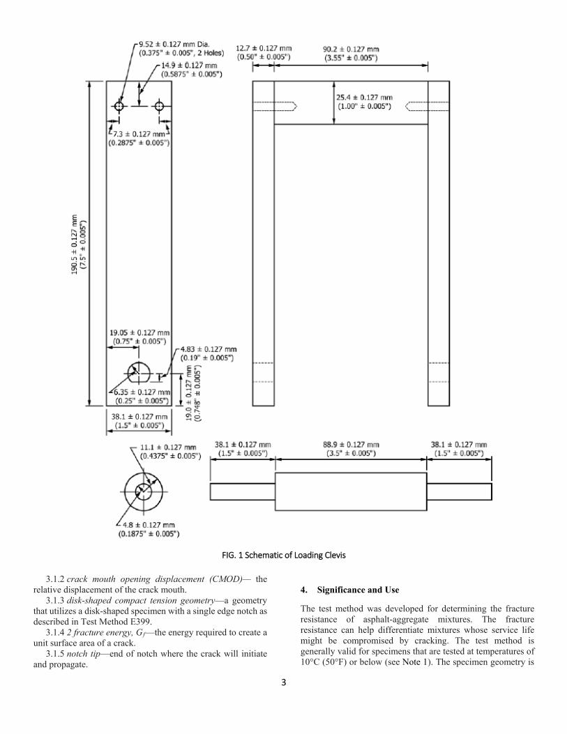
FIG. 1 Schematic of Loading Clevis
3.1.2 crack mouth opening displacement (CMOD)— the relative displacement of the crack mouth.
3.1.3 disk-shaped compact tension geometry—a geometry that utilizes a disk-shaped specimen with a single edge notch as described in Test Method E399.
3.1.4 2 fracture energy, Gf—the energy required to create a unit surface area of a crack.
3.1.5 notch tip—end of notch where the crack will initiate and propagate.
4. Significance and Use
The test method was developed for determining the fracture resistance of asphalt-aggregate mixtures. The fracture resistance can help differentiate mixtures whose service life might be compromised by cracking. The test method is generally valid for specimens that are tested at temperatures of 10°C (50°F) or below (see Note 1). The specimen geometry is
4
readily adapted to 150 mm diameter specimens, such as fabricated from Superpave (trademark) gyratory compactors (Test Method D6925) that are used for the asphalt concrete design process. The specimen geometry can also be adapted for forensic investigations using field cores of pavements where
thin lifts are present. This geometry has been found to produce satisfactory results for asphalt mixtures with nominal maximum aggregates size ranging from 4.75 to 19 mm.4
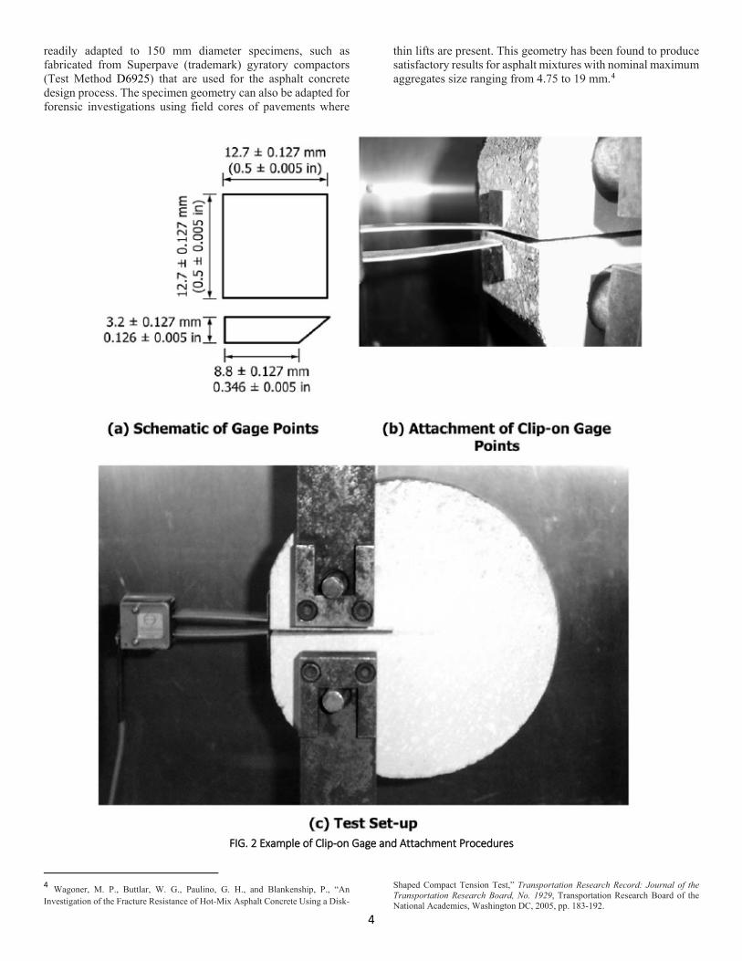
FIG. 2 Example of Clip-on Gage and Attachment Procedures
4 Wagoner, M. P., Buttlar, W. G., Paulino, G. H., and Blankenship, P., “An Investigation of the Fracture Resistance of Hot-Mix Asphalt Concrete Using a Disk-
Shaped Compact Tension Test,” Transportation Research Record: Journal of the Transportation Research Board, No. 1929, Transportation Research Board of the National Academies, Washington DC, 2005, pp. 183-192.

5
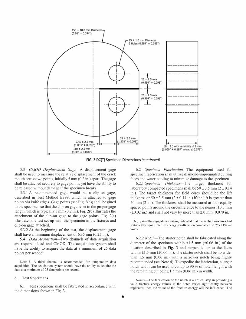
FIG. 3 DC(T) Specimen Dimensions
NOTE 1—The stiffness of the asphalt binder tends to influence the
assessment of a valid test as described in 7.4. For instance a soft asphalt binder, which may be required for a very cold climate might not lead to a mixture that would produce valid results at 10°C and conversely, a hard asphalt binder utilized in hot climates may require higher temperatures to provide any meaningful information.
NOTE 2—The quality of the results produced by this test method are dependent on the competence of the personnel performing the procedure and the capability, calibration, and maintenance of the equipment used. Agencies that meet the criteria of Specification D3666 are generally considered capable of competent and objective testing/sampling/ inspection/etc. Users of this test method are cautioned that compliance with Specification D3666 alone does not completely assure reliable results. Reliable results may depend on many factors; following the suggestions of Specification D3666 or some similar acceptable guidelines provides a means of evaluating and controlling some of those factors.
5. Apparatus
5.1 Loading—Specimens shall be tested in a loading frame capable of delivering a minimum of 20 kN (4500 lbf) in tension.
The load apparatus shall be capable of maintaining a constant crack mouth opening displacement within 2 % of the target value throughout the test. Closed-loop servo-hydraulic or servo-pneumatic test frames are highly recommended, but not required if the CMOD rate meets the specifications listed above. The load cell shall have a resolution of 20 N (4.5 lbf) or better.
5.2 Loading Fixtures—An example of a loading clevis suitable for testing of the specimen is shown in Fig. 1. The specimen is loaded through the pins which are allowed to roll freely on the flat surfaces of the loading clevis. Any clevis design may be used if the design demonstrates the ability to accomplish the same result. The recommended dimensions of the loading clevis are shown in Fig. 1.
6
FIG. 3 DC(T) Specimen Dimensions (continued)
5.3 CMOD Displacement Gage—A displacement gage
shall be used to measure the relative displacement of the crack mouth across two points, initially 5 mm (0.2 in.) apart. The gage shall be attached securely to gage points, yet have the ability to be released without damage if the specimen breaks.
5.3.1 A recommended gage would be a clip-on gage, described in Test Method E399, which is attached to gage points via knife edges. Gage points (see Fig. 2(a)) shall be glued to the specimen so that the clip-on gage is set to the proper gage length, which is typically 5 mm (0.2 in.). Fig. 2(b) illustrates the attachment of the clip-on gage to the gage points. Fig. 2(c) illustrates the test set-up with the specimen in the fixtures and clip-on gage attached.
5.3.2 At the beginning of the test, the displacement gage shall have a minimum displacement of 6.35 mm (0.25 in.).
5.4 Data Acquisition—Two channels of data acquisition are required: load and CMOD. The acquisition system shall have the ability to acquire the data at a minimum of 25 data points per second.
NOTE 3—A third channel is recommended for temperature data acquisition. The acquisition system should have the ability to acquire the data at a minimum of 25 data points per second. 6. Test Specimens
6.1 Test specimens shall be fabricated in accordance with the dimensions shown in Fig. 3.
6.2 Specimen Fabrication—The equipment used for specimen fabrication shall utilize diamond-impregnated cutting faces and water-cooling to minimize damage to the specimen.
6.2.1 Specimen Thickness—The target thickness for laboratory compacted specimens shall be 50 ± 3.5 mm (2 ± 0.14 in.). The target thickness for field cores should be the lift thickness or 50 ± 3.5 mm (2 ± 0.14 in.) if the lift is greater than 50 mm (2 in.). The thickness shall be measured at four equally spaced points around the circumference to the nearest ±0.5 mm (±0.02 in.) and shall not vary by more than 2.0 mm (0.079 in.).
NOTE 4—The ruggedness testing indicated that the asphalt mixtures had
statistically equal fracture energy results when compacted to 7% ±1% air voids.
6.2.2 Notch—The starter notch shall be fabricated along the
diameter of the specimen within ±1.5 mm (±0.06 in.) of the location described in Fig. 3 and perpendicular to the faces within ±1.5 mm (±0.06 in.). The starter notch shall be no wider than 1.5 mm (0.06 in.) with a narrower notch being highly recommended (see Note 4). To expedite the fabrication, a larger notch width can be used to cut up to 90 % of notch length with the remaining cut being 1.5 mm (0.06 in.) in width.
NOTE 5—The fabrication of the notch is a critical step in providing a valid fracture energy values. If the notch varies significantly between replicates, then the value of the fracture energy will be influenced. The
7
notch length is also critical since providing a fatigue crack of a known length, as recommended by Test Method E399, is difficult to produce in these materials. However, a notch which is relatively narrow compared to the maximum aggregate size will produce satisfactory results.
6.2.3 Flat Surface at Crack Mouth—The flat surface at the crack mouth shall be cut 90 ± 5° to the notch.
6.2.4 Loading Holes—The loading holes shall be fabricated 90 ± 5° to the faces of the specimen. The location of the loading holes shall not be greater than 5 mm (0.2 in.) from the specified locations.
6.2.5 Specimen Diameter, D—Measurements shall be taken at no less than two points to the nearest 60.5 mm (60.02 in.) around the circumference of the specimen and then averaged.
6.2.6 Initial ligament length, (W-a)—Measurements shall be taken on both sides of the specimen to the nearest 60.5 mm (60.02 in.) and averaged.
7. Procedure
7.1 Conditioning—The specimens shall be placed in a temperature-controlled chamber for a minimum of 2 h and a maximum of 16 h at the desired test temperature. The specimen temperature shall be within ±0.5°C (±1.0°F) of the desired test temperature throughout the conditioning time. A suggested test temperature of 10°C (18°F) greater than the low temperature performance grade of the asphalt binder, as defined in Specification D6373, is recommended.
7.2 After temperature conditioning, insert the specimen in loading fixtures quickly and apply a small seating load of no greater than 0.2 kN (45 lbf).
7.3 Wait until the test specimen temperature stabilizes within ±0.5°C of the desired test temperature and then perform the test with a constant crack mouth opening displacement rate of 0.017 mm/s (0.00067 in./s).
7.4 The test is complete when the post-peak load level has reduced to 0.1 kN (22 lbf). The validity of the test is a function of the ability to reach the specified load level (see Note 5).
NOTE 6—The complete failure of the specimen, that is, complete separation of the specimen into two pieces, is not feasible due to the closed-loop control through the CMOD. If the specimen completely fails without careful controls, the equipment could be damaged. Therefore, a minimum load limit was established to provide satisfactory test results. At higher temperatures, the load level may never reduce to this value within the typical range of a CMOD transducer due to crack blunting (notch tip opening without crack growth). In this case, the fracture energy may not be the dominate source of energy consumption and the test analysis methods presented in this specification would not be valid.
8. Interpretation of Fracture Energy
8.1 Variability of the test results can be reduced by data smoothing or elimination of extraneous electronic noise captured during the test. The following procedures outline a method to reduce the electronic noise associated with the CMOD data.
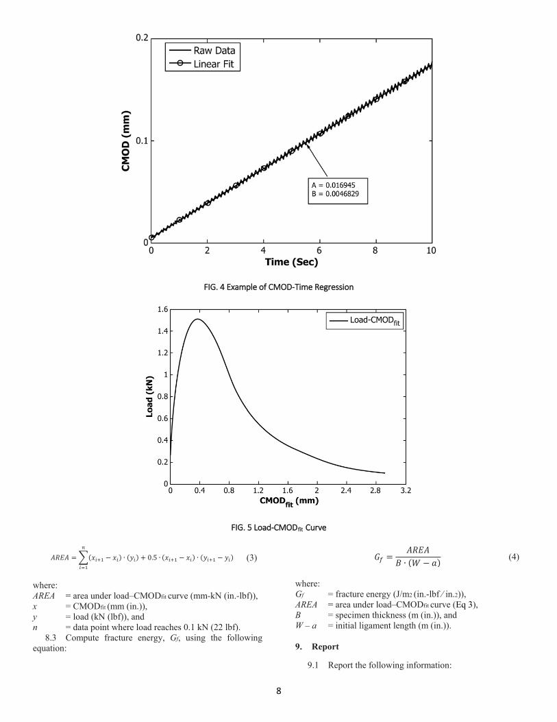
8.1.1 Plot CMOD versus time (see Fig. 4). 8.1.2 Use least squares regression (Eq 1) to fit a line through
the data to determine the slope (a1) and intercept (a0).
𝑌𝑌𝑖𝑖 = 𝑎𝑎0 + 𝑎𝑎1.𝑋𝑋𝑖𝑖 (1) where: Yi = CMOD data (mm (in.)), Xi = test time (s), and a0, a1 = regression parameters.
8.1.3 Using the regression parameters from Eq 1, create a smooth line to represent the CMOD data by using Eq 2.
𝐶𝐶𝐶𝐶𝐶𝐶𝐶𝐶𝑓𝑓𝑖𝑖𝑓𝑓 = 𝑎𝑎1.𝑇𝑇𝑇𝑇𝑇𝑇𝑇𝑇 (2) where: CMODfit = smoothed CMOD data (mm (in.)), a1 = slope of line (mm/s (in./s)), and Time = Xi from Eq 1.
8.1.4 For a valid test, the rate (a1) shall be within 5 % of the expected rate defined in 7.3 (±0.0008 mm/s (±0.00003 in./s)).
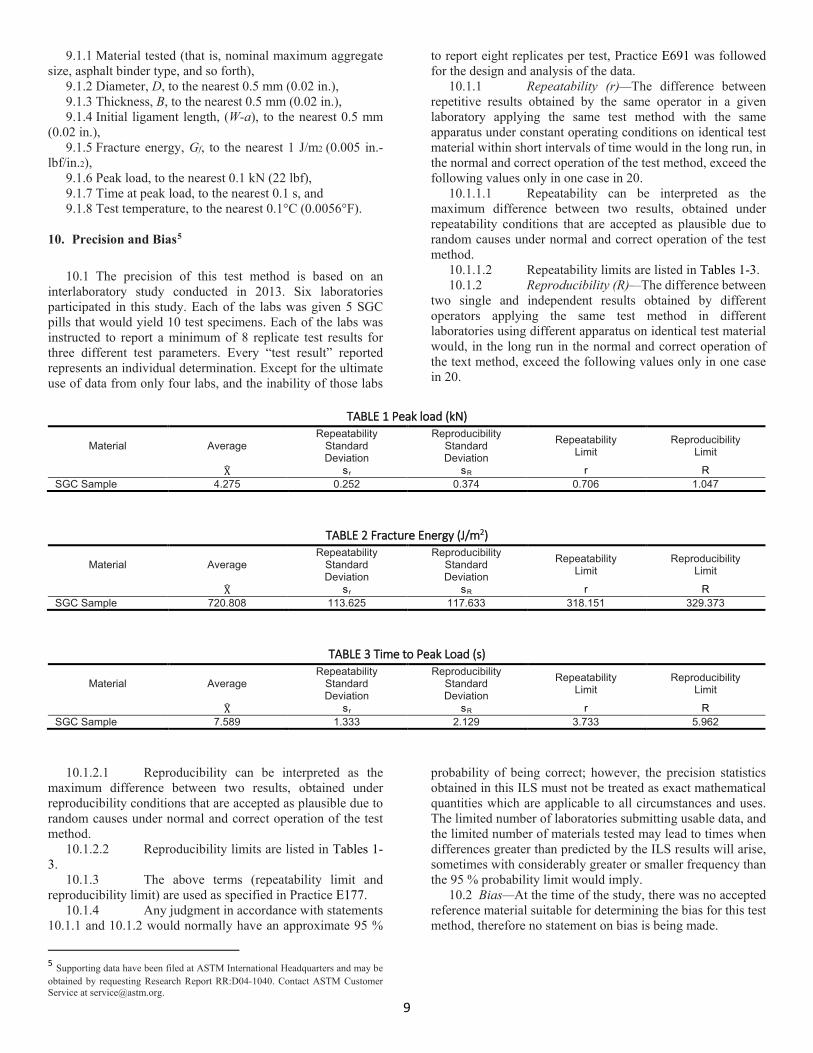
8.2 Plot Load-CMODfit data and compute the area under this curve (see Fig. 5). A suggested technique is using the quadrangle rule as shown in Eq 3.
8
FIG. 4 Example of CMOD-Time Regression
FIG. 5 Load-CMODfit Curve
𝐴𝐴𝐴𝐴𝐴𝐴𝐴𝐴 = �(𝑥𝑥𝑖𝑖+1 − 𝑥𝑥𝑖𝑖) ∙ (𝑦𝑦𝑖𝑖) + 0.5 ∙
𝑛𝑛
𝑖𝑖=1
(𝑥𝑥𝑖𝑖+1 − 𝑥𝑥𝑖𝑖) ∙ (𝑦𝑦𝑖𝑖+1 − 𝑦𝑦𝑖𝑖) (3)
where: AREA = area under load–CMODfit curve (mm-kN (in.-lbf)), x = CMODfit (mm (in.)), y = load (kN (lbf)), and n = data point where load reaches 0.1 kN (22 lbf).
8.3 Compute fracture energy, Gf, using the following equation:
𝐺𝐺𝑓𝑓 =𝐴𝐴𝐴𝐴𝐴𝐴𝐴𝐴
𝐵𝐵 ∙ (𝑊𝑊 − 𝑎𝑎) (4)
where: Gf = fracture energy (J/m2 (in.-lbf ⁄ in.2)), AREA = area under load–CMODfit curve (Eq 3), B = specimen thickness (m (in.)), and W – a = initial ligament length (m (in.)). 9. Report
9.1 Report the following information:
9
9.1.1 Material tested (that is, nominal maximum aggregate size, asphalt binder type, and so forth),
9.1.2 Diameter, D, to the nearest 0.5 mm (0.02 in.), 9.1.3 Thickness, B, to the nearest 0.5 mm (0.02 in.), 9.1.4 Initial ligament length, (W-a), to the nearest 0.5 mm
(0.02 in.), 9.1.5 Fracture energy, Gf, to the nearest 1 J/m2 (0.005 in.-
lbf/in.2), 9.1.6 Peak load, to the nearest 0.1 kN (22 lbf), 9.1.7 Time at peak load, to the nearest 0.1 s, and 9.1.8 Test temperature, to the nearest 0.1°C (0.0056°F).
10. Precision and Bias5
10.1 The precision of this test method is based on an
interlaboratory study conducted in 2013. Six laboratories participated in this study. Each of the labs was given 5 SGC pills that would yield 10 test specimens. Each of the labs was instructed to report a minimum of 8 replicate test results for three different test parameters. Every “test result” reported represents an individual determination. Except for the ultimate use of data from only four labs, and the inability of those labs
to report eight replicates per test, Practice E691 was followed for the design and analysis of the data.
10.1.1 Repeatability (r)—The difference between repetitive results obtained by the same operator in a given laboratory applying the same test method with the same apparatus under constant operating conditions on identical test material within short intervals of time would in the long run, in the normal and correct operation of the test method, exceed the following values only in one case in 20.
10.1.1.1 Repeatability can be interpreted as the maximum difference between two results, obtained under repeatability conditions that are accepted as plausible due to random causes under normal and correct operation of the test method.
10.1.1.2 Repeatability limits are listed in Tables 1-3. 10.1.2 Reproducibility (R)—The difference between
two single and independent results obtained by different operators applying the same test method in different laboratories using different apparatus on identical test material would, in the long run in the normal and correct operation of the text method, exceed the following values only in one case in 20.
TABLE 1 Peak load (kN)
Material Average Repeatability
Standard Deviation
Reproducibility Standard Deviation
Repeatability Limit
Reproducibility Limit
X� sr sR r R SGC Sample 4.275 0.252 0.374 0.706 1.047
TABLE 2 Fracture Energy (J/m2)
Material Average Repeatability
Standard Deviation
Reproducibility Standard Deviation
Repeatability Limit
Reproducibility Limit
X� sr sR r R SGC Sample 720.808 113.625 117.633 318.151 329.373
TABLE 3 Time to Peak Load (s)
Material Average Repeatability
Standard Deviation
Reproducibility Standard Deviation
Repeatability Limit
Reproducibility Limit
X� sr sR r R SGC Sample 7.589 1.333 2.129 3.733 5.962
10.1.2.1 Reproducibility can be interpreted as the maximum difference between two results, obtained under reproducibility conditions that are accepted as plausible due to random causes under normal and correct operation of the test method.
10.1.2.2 Reproducibility limits are listed in Tables 1-3.
10.1.3 The above terms (repeatability limit and reproducibility limit) are used as specified in Practice E177.
10.1.4 Any judgment in accordance with statements 10.1.1 and 10.1.2 would normally have an approximate 95 %
5 Supporting data have been filed at ASTM International Headquarters and may be obtained by requesting Research Report RR:D04-1040. Contact ASTM Customer Service at [email protected].
probability of being correct; however, the precision statistics obtained in this ILS must not be treated as exact mathematical quantities which are applicable to all circumstances and uses. The limited number of laboratories submitting usable data, and the limited number of materials tested may lead to times when differences greater than predicted by the ILS results will arise, sometimes with considerably greater or smaller frequency than the 95 % probability limit would imply.
10.2 Bias—At the time of the study, there was no accepted reference material suitable for determining the bias for this test method, therefore no statement on bias is being made.
10
10.3 The precision statement was determined through statistical examination of 107 results, from four laboratories, on a single SGC sample type using PG70-28 asphalt with 3⁄8 in. nominal mix. To judge the equivalency of two test results, it is recommended to choose the material closest in characteristics to the test material.
11. Keywords
11.1 asphalt concrete; crack growth; cracking; crack mouth opening displacement; disk-shaped compact tension test; fracture energy; temperature test
ASTM International takes no position respecting the validity of any patent rights asserted in connection with any item mentioned in this standard. Users of this standard are expressly advised that determination of the validity of any such patent rights, and the risk of infringement of such rights, are entirely their own responsibility.
This standard is subject to revision at any time by the responsible technical committee and must be reviewed
every five years and if not revised, either reapproved or withdrawn. Your comments are invited either for revision of this standard or for additional standards and should be addressed to ASTM International Headquarters. Your comments will receive careful consideration at a meeting of the responsible technical committee, which you may attend. If you feel that your comments have not received a fair hearing you should make your views known to the ASTM Committee on Standards, at the address shown below.
This standard is copyrighted by ASTM International, 100 Barr Harbor Drive, PO Box C700, West Conshohocken, PA 19428-2959, United States. Individual reprints (single or multiple copies) of this standard may be obtained by contacting ASTM at the above address or at 610-832-9585 (phone), 610-832-9555 (fax), or [email protected] (e-mail); or through the ASTM website (www.astm.org). Permission rights to photocopy the standard may also be secured from the Copyright Clearance Center, 222 Rosewood Drive, Danvers, MA 01923, Tel: (978) 646-2600; http://www.copyright.com/
Related Documents