Burnaby Hospital Redevelopment Project - Phase One Appendix 3H - Commissioning Project Agreement - Execution Version APPENDIX 3H COMMISSIONING Please see attached.

Welcome message from author
This document is posted to help you gain knowledge. Please leave a comment to let me know what you think about it! Share it to your friends and learn new things together.
Transcript

Burnaby Hospital Redevelopment Project - Phase One Appendix 3H - Commissioning Project Agreement - Execution Version
APPENDIX 3H
COMMISSIONING
Please see attached.
2
Appendix 3H - Commissioning (Burnaby Hospital Phase 1 – Redevelopment Project)
June 12th, 2020
Table of Contents Table of Contents .......................................................................................................................................... 2
1. Commissioning Team Organizational Chart ..................................................................................... 3 2. Commissioning Authority Scope of Work .......................................................................................... 4 3. Commissioning Plan Table of Contents ............................................................................................ 7 4. Functional Test Plan SAMPLE ........................................................................................................ 10 5. FF&E Handover Form SAMPLE ..................................................................................................... 12 6. Training Summary SAMPLE ........................................................................................................... 14 7. Training Plan SAMPLE ................................................................................................................... 16 8. Sampling Rate for Functional Testing ............................................................................................. 18 9. Commissioning Report Table of Contents ...................................................................................... 20 10. Systems Manual Table of Contents ............................................................................................ 21
3
Appendix 3H - Commissioning (Burnaby Hospital Phase 1 – Redevelopment Project)
June 12th, 2020
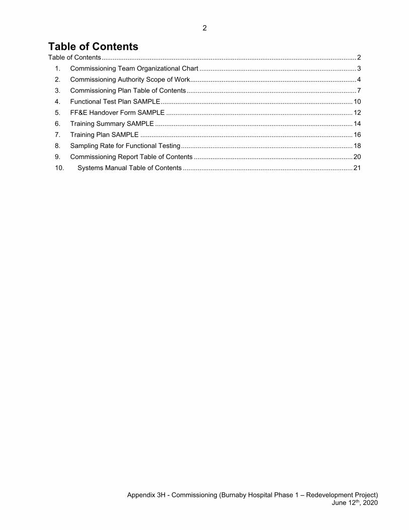
1. Commissioning Team Organizational Chart
4
Appendix 3H - Commissioning (Burnaby Hospital Phase 1 – Redevelopment Project) June 12th, 2020
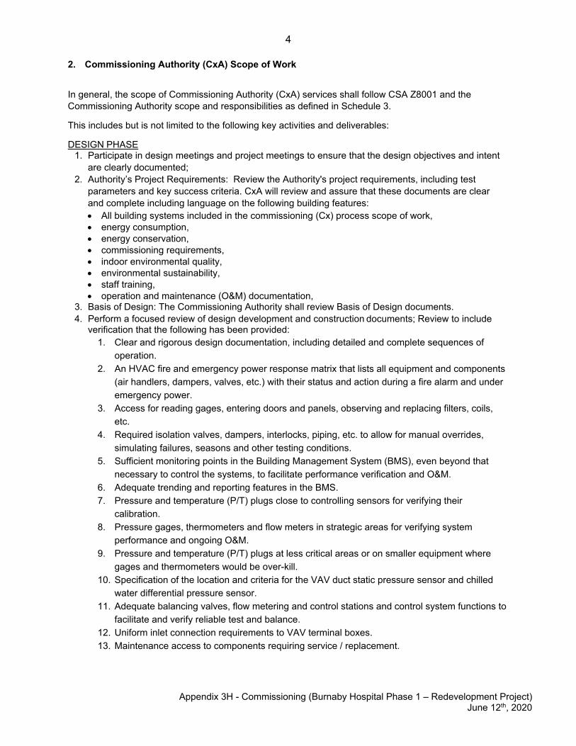
2. Commissioning Authority (CxA) Scope of Work
In general, the scope of Commissioning Authority (CxA) services shall follow CSA Z8001 and the Commissioning Authority scope and responsibilities as defined in Schedule 3.
This includes but is not limited to the following key activities and deliverables:
DESIGN PHASE 1. Participate in design meetings and project meetings to ensure that the design objectives and intent
are clearly documented;2. Authority’s Project Requirements: Review the Authority's project requirements, including test
parameters and key success criteria. CxA will review and assure that these documents are clear and complete including language on the following building features:• All building systems included in the commissioning (Cx) process scope of work,• energy consumption,• energy conservation,• commissioning requirements,• indoor environmental quality,• environmental sustainability,• staff training,• operation and maintenance (O&M) documentation,
3. Basis of Design: The Commissioning Authority shall review Basis of Design documents.4. Perform a focused review of design development and construction documents; Review to include
verification that the following has been provided:1. Clear and rigorous design documentation, including detailed and complete sequences of
operation.2. An HVAC fire and emergency power response matrix that lists all equipment and components
(air handlers, dampers, valves, etc.) with their status and action during a fire alarm and under emergency power.
3. Access for reading gages, entering doors and panels, observing and replacing filters, coils, etc.
4. Required isolation valves, dampers, interlocks, piping, etc. to allow for manual overrides, simulating failures, seasons and other testing conditions.
5. Sufficient monitoring points in the Building Management System (BMS), even beyond that necessary to control the systems, to facilitate performance verification and O&M.
6. Adequate trending and reporting features in the BMS.7. Pressure and temperature (P/T) plugs close to controlling sensors for verifying their
calibration.8. Pressure gages, thermometers and flow meters in strategic areas for verifying system
performance and ongoing O&M.9. Pressure and temperature (P/T) plugs at less critical areas or on smaller equipment where
gages and thermometers would be over-kill.10. Specification of the location and criteria for the VAV duct static pressure sensor and chilled
water differential pressure sensor.11. Adequate balancing valves, flow metering and control stations and control system functions to
facilitate and verify reliable test and balance.12. Uniform inlet connection requirements to VAV terminal boxes.13. Maintenance access to components requiring service / replacement.
5
Appendix 3H - Commissioning (Burnaby Hospital Phase 1 – Redevelopment Project) June 12th, 2020
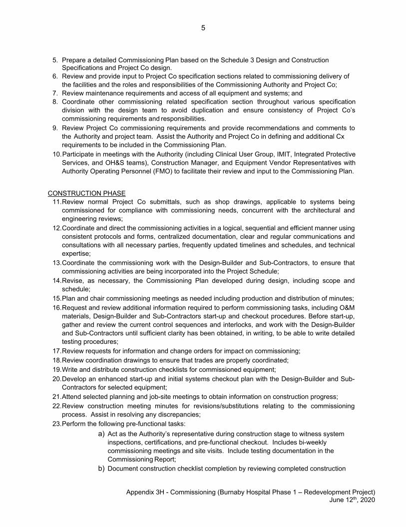
5. Prepare a detailed Commissioning Plan based on the Schedule 3 Design and Construction Specifications and Project Co design.
6. Review and provide input to Project Co specification sections related to commissioning delivery of the facilities and the roles and responsibilities of the Commissioning Authority and Project Co;
7. Review maintenance requirements and access of all equipment and systems; and8. Coordinate other commissioning related specification section throughout various specification
division with the design team to avoid duplication and ensure consistency of Project Co’s commissioning requirements and responsibilities.
9. Review Project Co commissioning requirements and provide recommendations and comments to the Authority and project team. Assist the Authority and Project Co in defining and additional Cx requirements to be included in the Commissioning Plan.
10. Participate in meetings with the Authority (including Clinical User Group, IMIT, Integrated Protective Services, and OH&S teams), Construction Manager, and Equipment Vendor Representatives with Authority Operating Personnel (FMO) to facilitate their review and input to the Commissioning Plan.
CONSTRUCTION PHASE 11. Review normal Project Co submittals, such as shop drawings, applicable to systems being
commissioned for compliance with commissioning needs, concurrent with the architectural andengineering reviews;
12. Coordinate and direct the commissioning activities in a logical, sequential and efficient manner usingconsistent protocols and forms, centralized documentation, clear and regular communications andconsultations with all necessary parties, frequently updated timelines and schedules, and technicalexpertise;
13. Coordinate the commissioning work with the Design-Builder and Sub-Contractors, to ensure thatcommissioning activities are being incorporated into the Project Schedule;
14. Revise, as necessary, the Commissioning Plan developed during design, including scope andschedule;
15. Plan and chair commissioning meetings as needed including production and distribution of minutes;16. Request and review additional information required to perform commissioning tasks, including O&M
materials, Design-Builder and Sub-Contractors start-up and checkout procedures. Before start-up,gather and review the current control sequences and interlocks, and work with the Design-Builderand Sub-Contractors until sufficient clarity has been obtained, in writing, to be able to write detailedtesting procedures;
17. Review requests for information and change orders for impact on commissioning;18. Review coordination drawings to ensure that trades are properly coordinated;19. Write and distribute construction checklists for commissioned equipment;20. Develop an enhanced start-up and initial systems checkout plan with the Design-Builder and Sub-
Contractors for selected equipment;21. Attend selected planning and job-site meetings to obtain information on construction progress;22. Review construction meeting minutes for revisions/substitutions relating to the commissioning
process. Assist in resolving any discrepancies;23. Perform the following pre-functional tasks:
a) Act as the Authority’s representative during construction stage to witness systeminspections, certifications, and pre-functional checkout. Includes bi-weeklycommissioning meetings and site visits. Include testing documentation in theCommissioning Report;
b) Document construction checklist completion by reviewing completed construction
6
Appendix 3H - Commissioning (Burnaby Hospital Phase 1 – Redevelopment Project)
June 12th, 2020
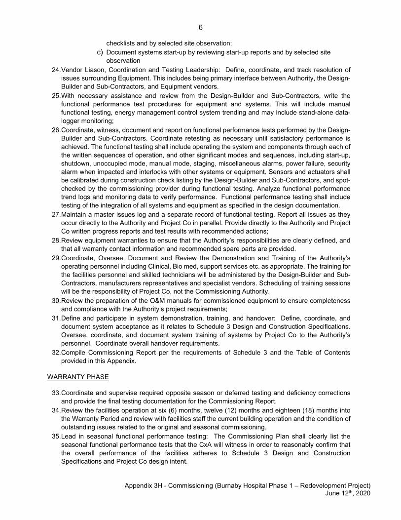
checklists and by selected site observation; c) Document systems start-up by reviewing start-up reports and by selected site
observation 24. Vendor Liason, Coordination and Testing Leadership: Define, coordinate, and track resolution of
issues surrounding Equipment. This includes being primary interface between Authority, the Design-Builder and Sub-Contractors, and Equipment vendors.
25. With necessary assistance and review from the Design-Builder and Sub-Contractors, write the functional performance test procedures for equipment and systems. This will include manual functional testing, energy management control system trending and may include stand-alone data-logger monitoring;
26. Coordinate, witness, document and report on functional performance tests performed by the Design-Builder and Sub-Contractors. Coordinate retesting as necessary until satisfactory performance is achieved. The functional testing shall include operating the system and components through each of the written sequences of operation, and other significant modes and sequences, including start-up, shutdown, unoccupied mode, manual mode, staging, miscellaneous alarms, power failure, security alarm when impacted and interlocks with other systems or equipment. Sensors and actuators shall be calibrated during construction check listing by the Design-Builder and Sub-Contractors, and spot-checked by the commissioning provider during functional testing. Analyze functional performance trend logs and monitoring data to verify performance. Functional performance testing shall include testing of the integration of all systems and equipment as specified in the design documentation.
27. Maintain a master issues log and a separate record of functional testing. Report all issues as they occur directly to the Authority and Project Co in parallel. Provide directly to the Authority and Project Co written progress reports and test results with recommended actions;
28. Review equipment warranties to ensure that the Authority’s responsibilities are clearly defined, and that all warranty contact information and recommended spare parts are provided.
29. Coordinate, Oversee, Document and Review the Demonstration and Training of the Authority’s operating personnel including Clinical, Bio med, support services etc. as appropriate. The training for the facilities personnel and skilled technicians will be administered by the Design-Builder and Sub-Contractors, manufacturers representatives and specialist vendors. Scheduling of training sessions will be the responsibility of Project Co, not the Commissioning Authority.
30. Review the preparation of the O&M manuals for commissioned equipment to ensure completeness and compliance with the Authority’s project requirements;
31. Define and participate in system demonstration, training, and handover: Define, coordinate, and document system acceptance as it relates to Schedule 3 Design and Construction Specifications. Oversee, coordinate, and document system training of systems by Project Co to the Authority’s personnel. Coordinate overall handover requirements.
32. Compile Commissioning Report per the requirements of Schedule 3 and the Table of Contents provided in this Appendix.
WARRANTY PHASE
33. Coordinate and supervise required opposite season or deferred testing and deficiency corrections and provide the final testing documentation for the Commissioning Report.
34. Review the facilities operation at six (6) months, twelve (12) months and eighteen (18) months into the Warranty Period and review with facilities staff the current building operation and the condition of outstanding issues related to the original and seasonal commissioning.
35. Lead in seasonal functional performance testing: The Commissioning Plan shall clearly list the seasonal functional performance tests that the CxA will witness in order to reasonably confirm that the overall performance of the facilities adheres to Schedule 3 Design and Construction Specifications and Project Co design intent.
7
Appendix 3H - Commissioning (Burnaby Hospital Phase 1 – Redevelopment Project)
June 12th, 2020
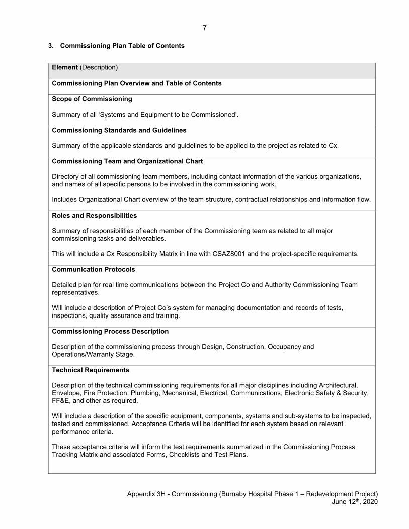
3. Commissioning Plan Table of Contents
Element (Description) Commissioning Plan Overview and Table of Contents Scope of Commissioning Summary of all ‘Systems and Equipment to be Commissioned’. Commissioning Standards and Guidelines Summary of the applicable standards and guidelines to be applied to the project as related to Cx. Commissioning Team and Organizational Chart Directory of all commissioning team members, including contact information of the various organizations, and names of all specific persons to be involved in the commissioning work. Includes Organizational Chart overview of the team structure, contractual relationships and information flow. Roles and Responsibilities Summary of responsibilities of each member of the Commissioning team as related to all major commissioning tasks and deliverables. This will include a Cx Responsibility Matrix in line with CSAZ8001 and the project-specific requirements. Communication Protocols Detailed plan for real time communications between the Project Co and Authority Commissioning Team representatives. Will include a description of Project Co’s system for managing documentation and records of tests, inspections, quality assurance and training. Commissioning Process Description Description of the commissioning process through Design, Construction, Occupancy and Operations/Warranty Stage. Technical Requirements Description of the technical commissioning requirements for all major disciplines including Architectural, Envelope, Fire Protection, Plumbing, Mechanical, Electrical, Communications, Electronic Safety & Security, FF&E, and other as required. Will include a description of the specific equipment, components, systems and sub-systems to be inspected, tested and commissioned. Acceptance Criteria will be identified for each system based on relevant performance criteria. These acceptance criteria will inform the test requirements summarized in the Commissioning Process Tracking Matrix and associated Forms, Checklists and Test Plans.
8
Appendix 3H - Commissioning (Burnaby Hospital Phase 1 – Redevelopment Project) June 12th, 2020
Element (Description)
Phased Commissioning Narrative – Phase 1A and Phase 1B
Section outlining the phased approach to commissioning that will be required based on the phased construction of Phase 1A (New Tower) and Phase 1B (Support Facilities Building) portions of the project.
This section will provide a summary of systems installed as part of Phase 1A that are also serving Phase 1B, along with details of how commissioning process will accommodate this phasing. This will include, at a minimum, Hydronic Heating and Chilled Water, Steam, Medical Gas, Domestic Hot Water, Air Handling Units and any other Phase 1A systems that will be serving Phase 1B.
Discussion will be provided regarding considerations such as available load at the time of Phase 1A and 1B Expansion and 1B Renovations; details of how Testing and Balancing (TAB) and Functional Testing Plans will verify system performance and spare capacity during Phase 1A to confirm adequate capacity will be available for Phase 1B; as well as which initial operating setpoints will be impacted by and updated during subsequent phases of work.
If any existing equipment or systems are modified as part of Phase 1B work, this section will provide a plan for how commissioning of these systems will be accomplished to ensure service continuity (mitigate impacts to existing operations).
Commissioning Schedule
Summarizes Commissioning Schedule requirements and provides a detailed schedule for performance of the Commissioning Work. Precedent conditions for New Tower Substantial Completion; SFB Expansion Substantial Completion; and Total Completion will be identified.
Increasing detail will be incorporated into the various Commissioning Schedule submissions throughout construction stage as subtrades provide the necessary input on sequencing and duration of specific tasks.
Authority's Project Requirements (Schedule 3)
Record of the Authority's Project Requirements for reference by the commissioning team.
Basis of Design
Narrative description of the design rationale, thought processes and assumptions made by the consultant to meet the Authority's Project Requirements. Provided as a reference for the commissioning team.
Commissioning Process Tracking Matrix and Dashboard
Table summary of all required commissioning deliverables down to the equipment level, identifying party responsible (contractor, vendor, 3rd party, CxA).
This summary is used by the CxA to track submission of completed test documentation and includes a dashboard summary used for progress reporting to all project stakeholders.
9
Appendix 3H - Commissioning (Burnaby Hospital Phase 1 – Redevelopment Project)
June 12th, 2020
Element (Description) Commissioning Forms, Checklists and Test Plans
1. Envelope Commissioning Forms 2. Prefunctional Checklists and Manufacturer Cx Report Templates 3. Functional Test Plans 4. Integration Test Plans 5. Clinical Functional Scenario Test Plans
Appendix will include a library of all documentation to be executed. Test documentation will include detailed procedures for conducting all of the Commissioning work, including reference documents, manufacturer’s recommendations, test standards, and narrative descriptions explaining how each test parameter will be measured or calculated, and a description of how test results will be reported. Documentation will be designed such that the reports will provide quantitative data for use as a baseline in comparing performance, determining deterioration over the applicable Design Life and assessing the sufficiency and performance of the Facilities. Demonstration and Training Summary Table summary of the proposed program for Demonstration and Training Sessions, including list of training activities, number of sessions, hours, trainee audience (stakeholder group), party responsible for producing training plan (vendor, contractor), and status of training plan submission. Training Plans Training plans will be provided for all systems and major equipment. Training plans will include details on trainer/presenter, proposed agenda with durations of each major topic, along with a package containing the training reference materials that will be presented. The CxA will work with the Authority to establish an agreed upon template for training plans, which will be followed by the Design-Builder and Sub-Contractors and equipment manufacturer’s representatives in preparation of project specific training plans. Building Enclosure Commissioning Plan Building Enclosure Commissioning Plan in line with the requirements of NIBS Guideline 3. Specific detail will be provided to define the unique approaches to building envelope/enclosure commissioning program that will be required for Phase 1A New Tower versus Phase 1B Support Facilites Building (new building envelope tie-in with the existing systems). Monitoring-Based Commissioning Plan In order to achieve LEED V4 Energy and Atmosphere Credit Enhanced Commissioning, Option 2: Enhanced and Monitoring-Based Commissioning, a program will be developed to assess performance of energy- and water-consuming systems post-Occupancy.
10
Appendix 3H - Commissioning (Burnaby Hospital Phase 1 – Redevelopment Project)
June 12th, 2020
4. Functional Test Plan SAMPLE
This document is provided as a representative sample to establish a standard level of detail and rigor.
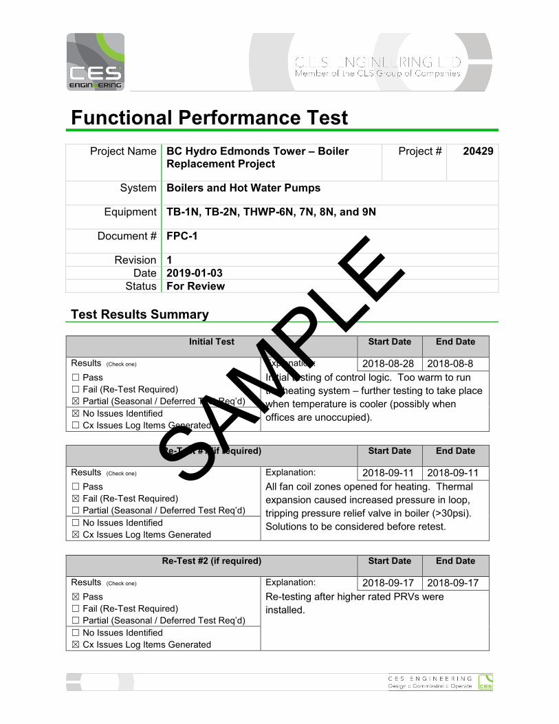
Functional Performance Test
Project Name BC Hydro Edmonds Tower – Boiler Replacement Project
Project # 20429
System Boilers and Hot Water Pumps
Equipment TB-1N, TB-2N, THWP-6N, 7N, 8N, and 9N
Document # FPC-1
Revision 1 Date 2019-01-03
Status For Review
Test Results Summary
Initial Test Start Date End Date
Results (Check one) Explanation: 2018-08-28 2018-08-8 ☐ Pass ☐ Fail (Re-Test Required) ☒ Partial (Seasonal / Deferred Test Req’d)
Initial testing of control logic. Too warm to run the heating system – further testing to take place when temperature is cooler (possibly when offices are unoccupied). ☒ No Issues Identified
☐ Cx Issues Log Items Generated
Re-Test #1 (if required) Start Date End Date
Results (Check one) Explanation: 2018-09-11 2018-09-11 ☐ Pass ☒ Fail (Re-Test Required) ☐ Partial (Seasonal / Deferred Test Req’d)
All fan coil zones opened for heating. Thermal expansion caused increased pressure in loop, tripping pressure relief valve in boiler (>30psi). Solutions to be considered before retest. ☐ No Issues Identified
☒ Cx Issues Log Items Generated
Re-Test #2 (if required) Start Date End Date
Results (Check one) Explanation: 2018-09-17 2018-09-17 ☒ Pass ☐ Fail (Re-Test Required) ☐ Partial (Seasonal / Deferred Test Req’d)
Re-testing after higher rated PRVs were installed.
☐ No Issues Identified ☒ Cx Issues Log Items Generated
SAMPLE
Functional Performance Test Condensing Boilers and Primary Hot Water Pumps
2019-01-03 Page 2 of 23
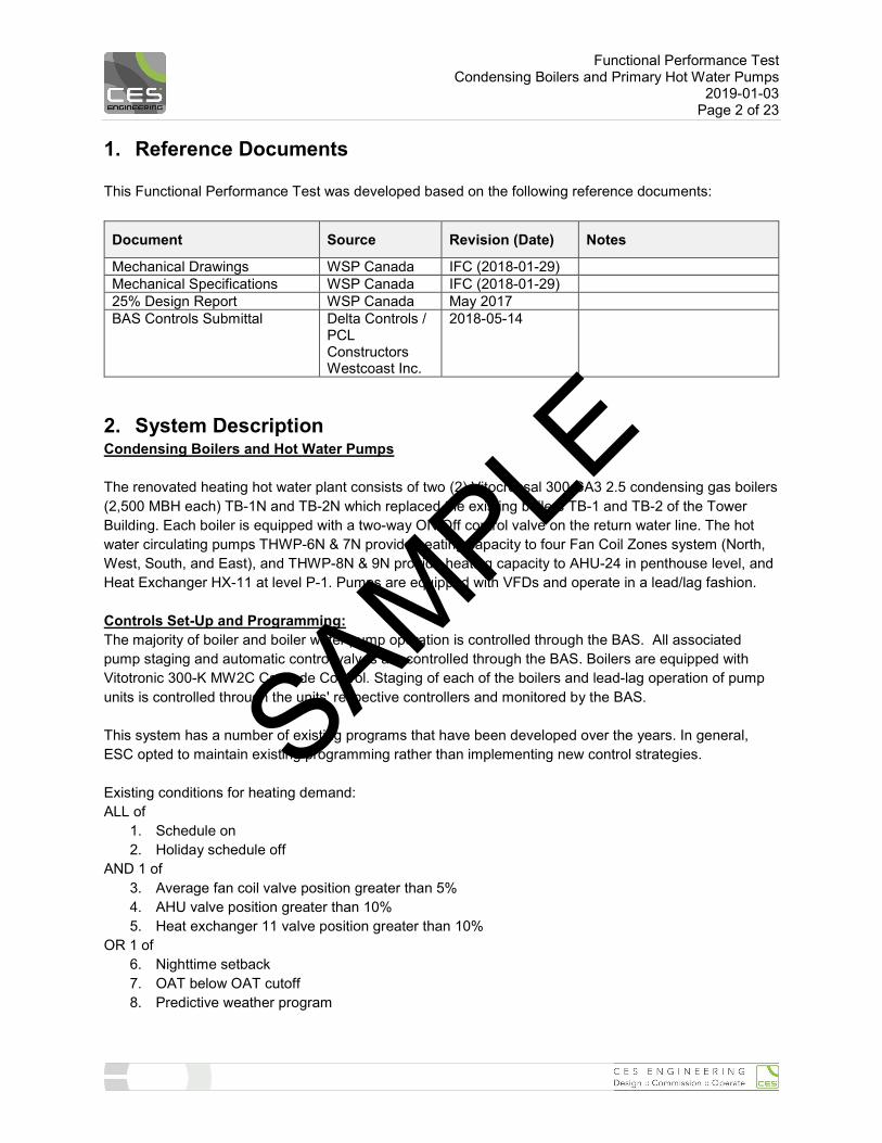
1. Reference Documents This Functional Performance Test was developed based on the following reference documents:
Document Source Revision (Date) Notes
Mechanical Drawings WSP Canada IFC (2018-01-29) Mechanical Specifications WSP Canada IFC (2018-01-29) 25% Design Report WSP Canada May 2017 BAS Controls Submittal Delta Controls /
PCL Constructors Westcoast Inc.
2018-05-14
2. System Description Condensing Boilers and Hot Water Pumps The renovated heating hot water plant consists of two (2) Vitocrossal 300 CA3 2.5 condensing gas boilers (2,500 MBH each) TB-1N and TB-2N which replaced the existing boilers TB-1 and TB-2 of the Tower Building. Each boiler is equipped with a two-way ON/Off control valve on the return water line. The hot water circulating pumps THWP-6N & 7N provide heating capacity to four Fan Coil Zones system (North, West, South, and East), and THWP-8N & 9N provide heating capacity to AHU-24 in penthouse level, and Heat Exchanger HX-11 at level P-1. Pumps are equipped with VFDs and operate in a lead/lag fashion. Controls Set-Up and Programming: The majority of boiler and boiler water pump operation is controlled through the BAS. All associated pump staging and automatic control valves are controlled through the BAS. Boilers are equipped with Vitotronic 300-K MW2C Cascade Control. Staging of each of the boilers and lead-lag operation of pump units is controlled through the units' respective controllers and monitored by the BAS. This system has a number of existing programs that have been developed over the years. In general, ESC opted to maintain existing programming rather than implementing new control strategies. Existing conditions for heating demand: ALL of
1. Schedule on 2. Holiday schedule off
AND 1 of 3. Average fan coil valve position greater than 5% 4. AHU valve position greater than 10% 5. Heat exchanger 11 valve position greater than 10%
OR 1 of 6. Nighttime setback 7. OAT below OAT cutoff 8. Predictive weather program
SAMPLE
Functional Performance Test Condensing Boilers and Primary Hot Water Pumps
2019-01-03 Page 3 of 23
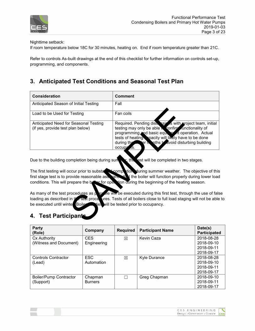
Nighttime setback: If room temperature below 18C for 30 minutes, heating on. End if room temperature greater than 21C. Refer to controls As-built drawings at the end of this checklist for further information on controls set-up, programming, and components.
3. Anticipated Test Conditions and Seasonal Test Plan
Consideration Comment Anticipated Season of Initial Testing
Fall
Load to be Used for Testing
Fan coils
Anticipated Need for Seasonal Testing (if yes, provide test plan below)
Required. Pending discussions with project team, initial testing may only be able to confirm functionality of programming and basic equipment operation. Actual tests of heating capacity will likely have to be done during the winter months to avoid disturbing building occupants.
Due to the building completion being during summer, this test will be completed in two stages. The first testing will occur prior to substantial completion, during summer weather. The objective of this first stage test is to provide reasonable assurance that the boiler will function properly during lower load conditions. This will prepare the boiler for operation during the beginning of the heating season. As many of the test procedures as possible will be executed during this first test, through the use of false loading as described in the test procedures. Tests of all boilers close to full load staging will not be able to be executed until winter. Boiler safeties will be tested prior to occupancy.
4. Test Participants
Party (Role) Company Required Participant Name Date(s)
Participated Cx Authority (Witness and Document)
CES Engineering
☒ Kevin Caza 2018-08-28 2018-09-10 2018-09-11 2018-09-17
Controls Contractor (Lead)
ESC Automation
☒ Kyle Durance 2018-08-28 2018-09-10 2018-09-11 2018-09-17
Boiler/Pump Contractor (Support)
Chapman Burners
☐ Greg Chapman 2018-09-10 2018-09-11 2018-09-17
SAMPLE
Functional Performance Test Condensing Boilers and Primary Hot Water Pumps
2019-01-03 Page 4 of 23
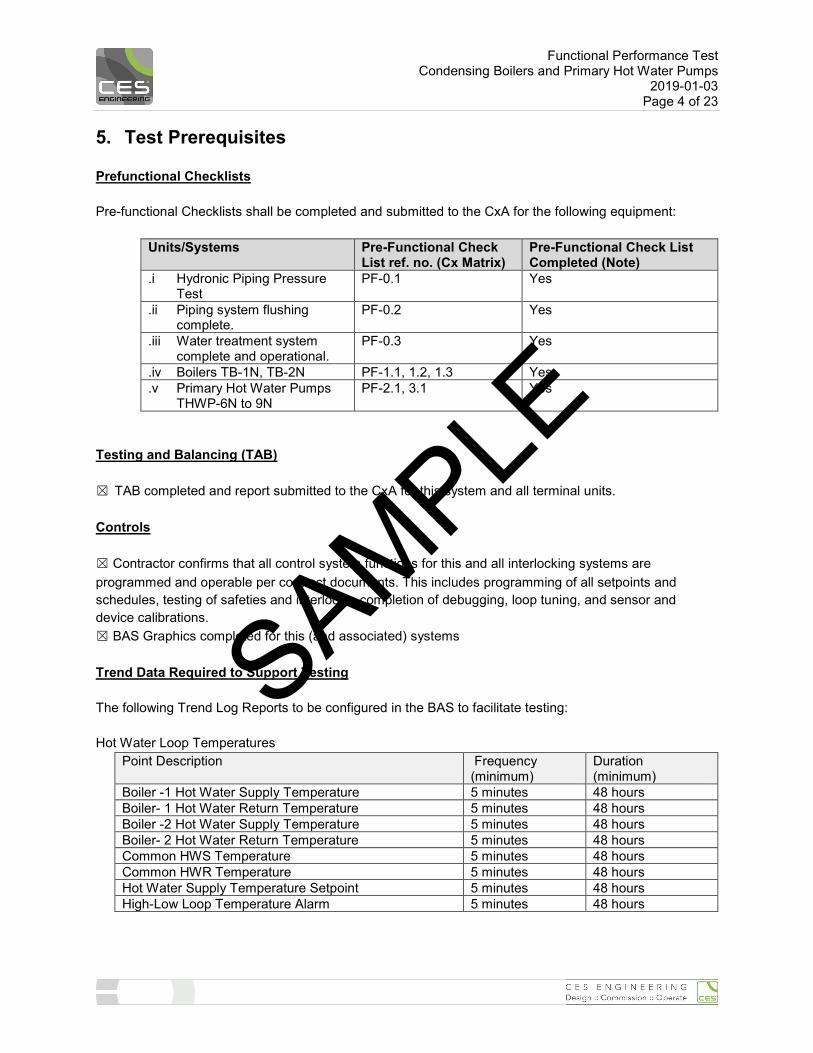
5. Test Prerequisites Prefunctional Checklists Pre-functional Checklists shall be completed and submitted to the CxA for the following equipment:
Units/Systems Pre-Functional Check List ref. no. (Cx Matrix)
Pre-Functional Check List Completed (Note)
.i Hydronic Piping Pressure Test
PF-0.1 Yes
.ii Piping system flushing complete.
PF-0.2 Yes
.iii Water treatment system complete and operational.
PF-0.3 Yes
.iv Boilers TB-1N, TB-2N PF-1.1, 1.2, 1.3 Yes
.v Primary Hot Water Pumps THWP-6N to 9N
PF-2.1, 3.1 Yes
Testing and Balancing (TAB) ☒ TAB completed and report submitted to the CxA for this system and all terminal units. Controls ☒ Contractor confirms that all control system functions for this and all interlocking systems are programmed and operable per contract documents. This includes programming of all setpoints and schedules, testing of safeties and interlocks, completion of debugging, loop tuning, and sensor and device calibrations. ☒ BAS Graphics completed for this (and associated) systems Trend Data Required to Support Testing The following Trend Log Reports to be configured in the BAS to facilitate testing: Hot Water Loop Temperatures
Point Description Frequency (minimum)
Duration (minimum)
Boiler -1 Hot Water Supply Temperature 5 minutes 48 hours Boiler- 1 Hot Water Return Temperature 5 minutes 48 hours Boiler -2 Hot Water Supply Temperature 5 minutes 48 hours Boiler- 2 Hot Water Return Temperature 5 minutes 48 hours Common HWS Temperature 5 minutes 48 hours Common HWR Temperature 5 minutes 48 hours Hot Water Supply Temperature Setpoint 5 minutes 48 hours High-Low Loop Temperature Alarm 5 minutes 48 hours
SAMPLE
Functional Performance Test Condensing Boilers and Primary Hot Water Pumps
2019-01-03 Page 5 of 23
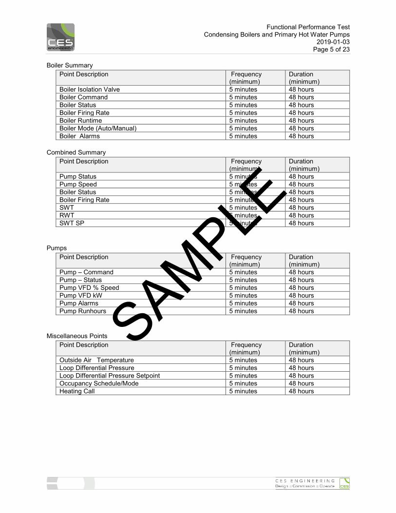
Boiler Summary Point Description Frequency
(minimum) Duration (minimum)
Boiler Isolation Valve 5 minutes 48 hours Boiler Command 5 minutes 48 hours Boiler Status 5 minutes 48 hours Boiler Firing Rate 5 minutes 48 hours Boiler Runtime 5 minutes 48 hours Boiler Mode (Auto/Manual) 5 minutes 48 hours Boiler Alarms 5 minutes 48 hours
Combined Summary
Point Description Frequency (minimum)
Duration (minimum)
Pump Status 5 minutes 48 hours Pump Speed 5 minutes 48 hours Boiler Status 5 minutes 48 hours Boiler Firing Rate 5 minutes 48 hours SWT 5 minutes 48 hours RWT 5 minutes 48 hours SWT SP 5 minutes 48 hours
Pumps
Point Description Frequency (minimum)
Duration (minimum)
Pump – Command 5 minutes 48 hours Pump – Status 5 minutes 48 hours Pump VFD % Speed 5 minutes 48 hours Pump VFD kW 5 minutes 48 hours Pump Alarms 5 minutes 48 hours Pump Runhours 5 minutes 48 hours
Miscellaneous Points
Point Description Frequency (minimum)
Duration (minimum)
Outside Air Temperature 5 minutes 48 hours Loop Differential Pressure 5 minutes 48 hours Loop Differential Pressure Setpoint 5 minutes 48 hours Occupancy Schedule/Mode 5 minutes 48 hours Heating Call 5 minutes 48 hours
SAMPLE
Functional Performance Test Condensing Boilers and Primary Hot Water Pumps
2019-01-03 Page 6 of 23
Supplies Required for Testing (to be provided by contractor)
☒ Operator’s workstation with BAS software
Review of Functional Test Procedures ☒ These functional test procedures have been reviewed and approved by installing contractor(s) ☒ False loading equipment, system and procedures ready as required by test plan (e.g. cross-over piping
connections between heating/cooling systems, etc.)
SAMPLE
Functional Performance Test Condensing Boilers and Primary Hot Water Pumps
2019-01-03 Page 7 of 23
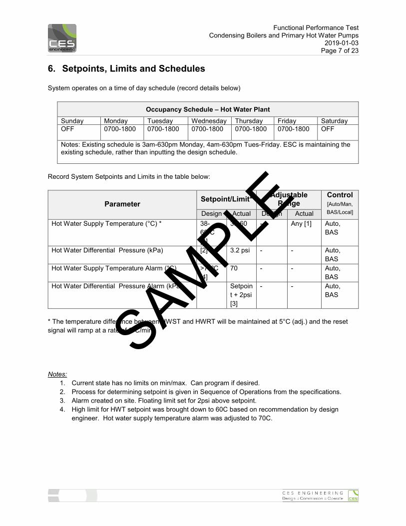
6. Setpoints, Limits and Schedules System operates on a time of day schedule (record details below)
Occupancy Schedule – Hot Water Plant Sunday Monday Tuesday Wednesday Thursday Friday Saturday OFF
0700-1800 0700-1800 0700-1800 0700-1800 0700-1800 OFF
Notes: Existing schedule is 3am-630pm Monday, 4am-630pm Tues-Friday. ESC is maintaining the existing schedule, rather than inputting the design schedule.
Record System Setpoints and Limits in the table below:
Parameter Setpoint/Limit* Adjustable Range
Control [Auto/Man, BAS/Local] Design Actual Design Actual
Hot Water Supply Temperature (°C) * 38-60⁰C [4]
38-60 - Any [1] Auto, BAS
Hot Water Differential Pressure (kPa) [2] 3.2 psi - - Auto, BAS
Hot Water Supply Temperature Alarm (°C) >70⁰C [4]
70 - - Auto, BAS
Hot Water Differential Pressure Alarm (kPa) - Setpoint + 2psi [3]
- - Auto, BAS
* The temperature difference between HWST and HWRT will be maintained at 5°C (adj.) and the reset signal will ramp at a rate of 2°C/min. Notes:
1. Current state has no limits on min/max. Can program if desired. 2. Process for determining setpoint is given in Sequence of Operations from the specifications. 3. Alarm created on site. Floating limit set for 2psi above setpoint. 4. High limit for HWT setpoint was brought down to 60C based on recommendation by design
engineer. Hot water supply temperature alarm was adjusted to 70C.
SAMPLE
Functional Performance Test Condensing Boilers and Primary Hot Water Pumps
2019-01-03 Page 8 of 23
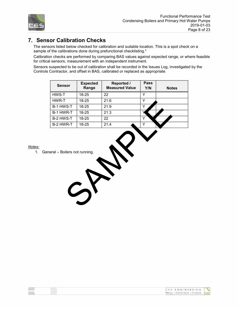
7. Sensor Calibration Checks The sensors listed below checked for calibration and suitable location. This is a spot check on a sample of the calibrations done during prefunctional checklisting.* Calibration checks are performed by comparing BAS values against expected range, or where feasible for critical sensors, measurement with an independent instrument. Sensors suspected to be out of calibration shall be recorded in the Issues Log, investigated by the Controls Contractor, and offset in BAS, calibrated or replaced as appropriate.
Sensor Expected Range
Reported / Measured Value
Pass Y/N
Notes
HWS-T 18-25 22 Y HWR-T 18-25 21.6 Y B-1 HWS-T 18-25 21.9 Y B-1 HWR-T 18-25 21.3 Y B-2 HWS-T 18-25 22 Y B-2 HWR-T 18-25 21.4 Y
Notes:
1. General – Boilers not running.
SAMPLE
Functional Performance Test Condensing Boilers and Primary Hot Water Pumps
2019-01-03 Page 9 of 23
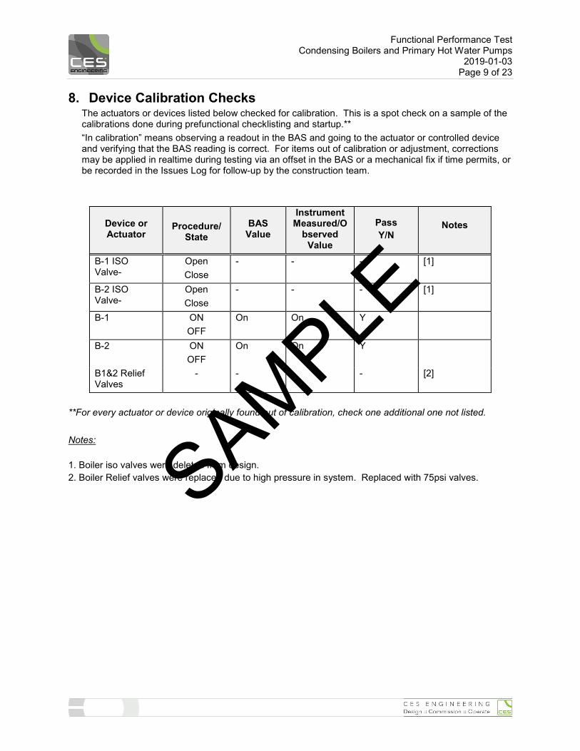
8. Device Calibration Checks The actuators or devices listed below checked for calibration. This is a spot check on a sample of the calibrations done during prefunctional checklisting and startup.** “In calibration” means observing a readout in the BAS and going to the actuator or controlled device and verifying that the BAS reading is correct. For items out of calibration or adjustment, corrections may be applied in realtime during testing via an offset in the BAS or a mechanical fix if time permits, or be recorded in the Issues Log for follow-up by the construction team.
Device or Actuator
Procedure/
State BAS
Value
Instrument Measured/O
bserved Value
Pass Y/N
Notes
B-1 ISO Valve-
Open Close
- - - [1]
B-2 ISO Valve-
Open Close
- - - [1]
B-1 ON OFF
On On Y
B-2 ON OFF
On On Y
B1&2 Relief Valves
- - - - [2]
**For every actuator or device originally found out of calibration, check one additional one not listed. Notes: 1. Boiler iso valves were deleted from design. 2. Boiler Relief valves were replaced due to high pressure in system. Replaced with 75psi valves. SAMPLE
Functional Performance Test Condensing Boilers and Primary Hot Water Pumps
2019-01-03 Page 10 of 23
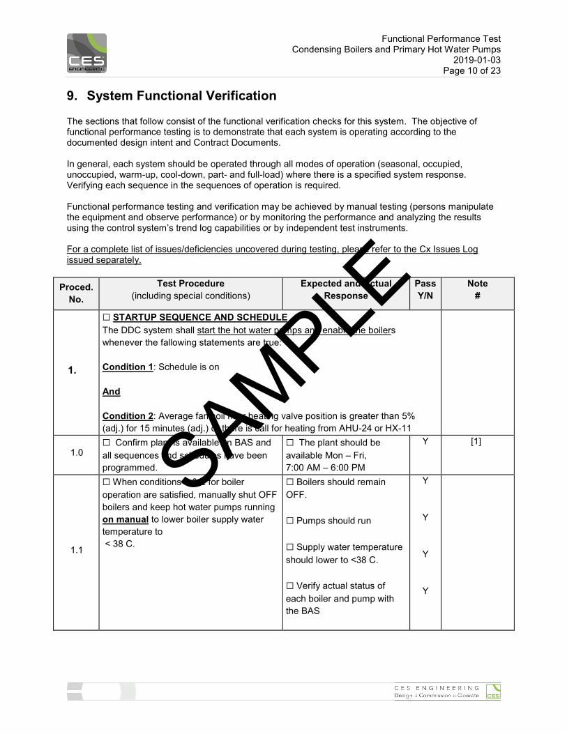
9. System Functional Verification The sections that follow consist of the functional verification checks for this system. The objective of functional performance testing is to demonstrate that each system is operating according to the documented design intent and Contract Documents. In general, each system should be operated through all modes of operation (seasonal, occupied, unoccupied, warm-up, cool-down, part- and full-load) where there is a specified system response. Verifying each sequence in the sequences of operation is required. Functional performance testing and verification may be achieved by manual testing (persons manipulate the equipment and observe performance) or by monitoring the performance and analyzing the results using the control system’s trend log capabilities or by independent test instruments. For a complete list of issues/deficiencies uncovered during testing, please refer to the Cx Issues Log issued separately.
Proced. No.
Test Procedure (including special conditions)
Expected and Actual Response
Pass Y/N
Note #
1.
☐ STARTUP SEQUENCE AND SCHEDULE The DDC system shall start the hot water pumps and enable the boilers whenever the fallowing statements are true: Condition 1: Schedule is on And Condition 2: Average fan coil riser heating valve position is greater than 5% (adj.) for 15 minutes (adj.) or there is call for heating from AHU-24 or HX-11
1.0 ☐ Confirm plant is available on BAS and all sequences and schedules have been programmed.
☐ The plant should be available Mon – Fri, 7:00 AM – 6:00 PM
Y [1]
1.1
☐ When conditions 1 & 2 for boiler operation are satisfied, manually shut OFF boilers and keep hot water pumps running on manual to lower boiler supply water temperature to < 38 C.
☐ Boilers should remain OFF. ☐ Pumps should run ☐ Supply water temperature should lower to <38 C. ☐ Verify actual status of each boiler and pump with the BAS
Y
Y
Y
Y
SAMPLE
Functional Performance Test Condensing Boilers and Primary Hot Water Pumps
2019-01-03 Page 11 of 23
Proced. No.
Test Procedure (including special conditions)
Expected and Actual Response
Pass Y/N
Note #
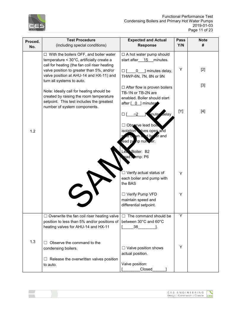
1.2
☐ With the boilers OFF, and boiler water temperature < 30°C, artificially create a call for heating (the fan coil riser heating valve position to greater than 5%, and/or valve position at AHU-14 and HX-11) and turn all systems to auto. Note: Ideally call for heating should be created by raising the room temperature setpoint. This test includes the greatest number of system components.
☐ A hot water pump should start after 15 minutes. ☐ [____0___] minutes delay, THWP-6N, 7N, 8N or 9N ☐ After flow is proven boilers TB-1N or TB-2N are enabled. Boiler should start after [ 0 ] minutes. ☐ [___~2___] minutes delay ☐ Observe lead boiler isolation valves open and note down lead boiler and lead pump number. Lead Boiler: B2 Lead Pump: P6 ☐ Verify actual status of each boiler and pump with the BAS ☐ Verify Pump VFD maintain speed and differential setpoint.
Y
[Y]
Y
Y
[2]
[3]
[4]
1.3
☐ Overwrite the fan coil riser heating valve position to less than 5% and/or positions of heating valves for AHU-14 and HX-11 ☐ Observe the command to the condensing boilers. ☐ Release the overwritten valves position to auto.
☐ The command should be between 30°C and 60°C [_____38________]. ☐ Valve position shows actual position. Valve position: [________Closed______]
Y
Y
SAMPLE
Functional Performance Test Condensing Boilers and Primary Hot Water Pumps
2019-01-03 Page 12 of 23
Proced. No.
Test Procedure (including special conditions)
Expected and Actual Response
Pass Y/N
Note #
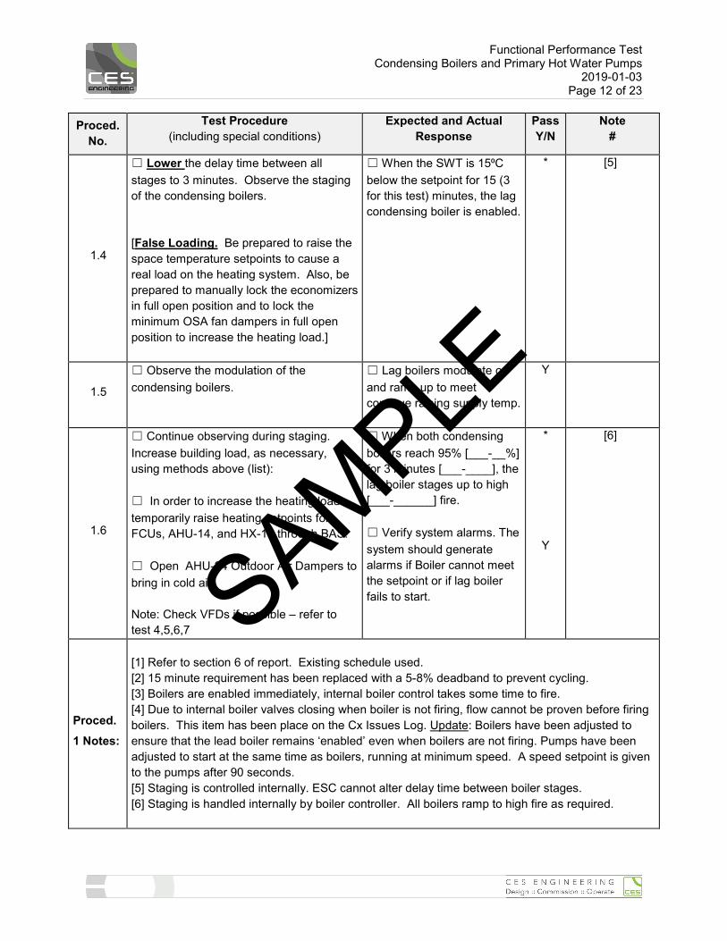
1.4
☐ Lower the delay time between all stages to 3 minutes. Observe the staging of the condensing boilers. [False Loading. Be prepared to raise the space temperature setpoints to cause a real load on the heating system. Also, be prepared to manually lock the economizers in full open position and to lock the minimum OSA fan dampers in full open position to increase the heating load.]
☐ When the SWT is 15⁰C below the setpoint for 15 (3 for this test) minutes, the lag condensing boiler is enabled.
* [5]
1.5
☐ Observe the modulation of the condensing boilers.
☐ Lag boilers modulate on and ramp up to meet continue raising supply temp.
Y
1.6
☐ Continue observing during staging. Increase building load, as necessary, using methods above (list): ☐ In order to increase the heating load temporarily raise heating setpoints for FCUs, AHU-14, and HX-11 through BAS. ☐ Open AHU-24 Outdoor Air Dampers to bring in cold air. Note: Check VFDs if possible – refer to test 4,5,6,7
☐ When both condensing boilers reach 95% [___-__%] for 3 minutes [___-____], the lag boiler stages up to high [___-______] fire. ☐ Verify system alarms. The system should generate alarms if Boiler cannot meet the setpoint or if lag boiler fails to start.
*
Y
[6]
Proced. 1 Notes:
[1] Refer to section 6 of report. Existing schedule used. [2] 15 minute requirement has been replaced with a 5-8% deadband to prevent cycling. [3] Boilers are enabled immediately, internal boiler control takes some time to fire. [4] Due to internal boiler valves closing when boiler is not firing, flow cannot be proven before firing boilers. This item has been place on the Cx Issues Log. Update: Boilers have been adjusted to ensure that the lead boiler remains ‘enabled’ even when boilers are not firing. Pumps have been adjusted to start at the same time as boilers, running at minimum speed. A speed setpoint is given to the pumps after 90 seconds. [5] Staging is controlled internally. ESC cannot alter delay time between boiler stages. [6] Staging is handled internally by boiler controller. All boilers ramp to high fire as required.
SAMPLE
Functional Performance Test Condensing Boilers and Primary Hot Water Pumps
2019-01-03 Page 13 of 23
Proced. No.
Test Procedure (including special conditions)
Expected and Actual Response
Pass Y/N
Note #
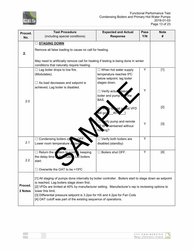
2.
☐ STAGING DOWN
Remove all false loading to cause no call for heating.
May need to artificially remove call for heating if testing is being done in winter conditions that naturally require heating.
2.0
☐ Lag boiler drops to low fire. (Modulates). ☐ As load decreases and setpoint is achieved, Lag boiler is disabled.
☐ When hot water supply temperature reaches 5⁰C below setpoint, lag boiler stages down. ☐ Verify actual status of boiler and pump with the BAS. ☐ Verify lowest speed VFD will go: [__40%___] ☐ Verify pump and remote dP SP maintained without hunting?
Y
Y
Y
[1]
[2]
[3]
2.1 ☐ Condensing boilers cycling OFF: Lower room temperature setpoints
☐ Verify both boilers are disabled.(standby)
Y
2.2
☐ Return the system to normal, keeping the delay time at 3 minutes. Let boilers start. ☐ Overwrite the OAT to be >15⁰C
☐ Boilers shut OFF. Y [4]
Proced. 2 Notes
[1] All staging of pumps done internally by boiler controller. Boilers start to stage down as setpoint is reached. Lag boilers stage down first. [2] VFDs are limited at 40% by manufacturer setting. Manufacturer’s rep is reviewing options to lower this limit. [3] Differential pressure setpoint is 3.2psi for HX and 4.2psi for Fan Coils [4] OAT cutoff was part of the existing sequence of operations.
SAMPLE
Functional Performance Test Condensing Boilers and Primary Hot Water Pumps
2019-01-03 Page 14 of 23
Proced. No.
Test Procedure (including special conditions)
Expected and Actual Response
Pass Y/N
Note #
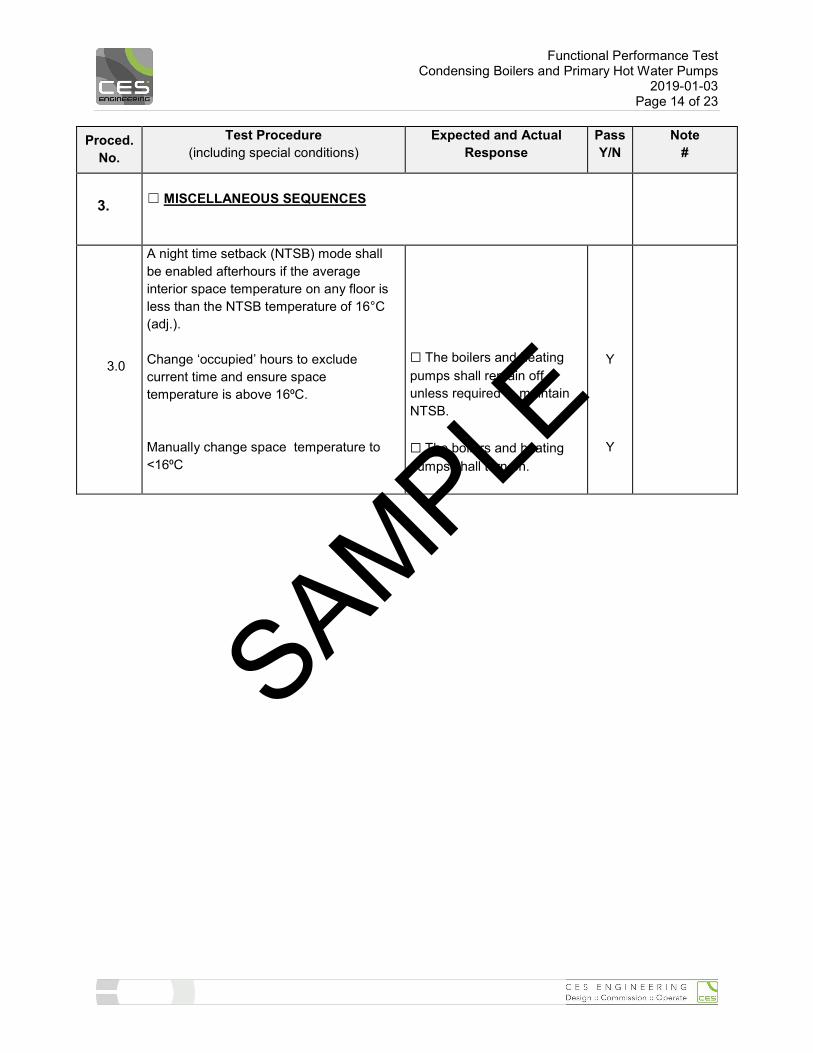
3. ☐ MISCELLANEOUS SEQUENCES
3.0
A night time setback (NTSB) mode shall be enabled afterhours if the average interior space temperature on any floor is less than the NTSB temperature of 16°C (adj.). Change ‘occupied’ hours to exclude current time and ensure space temperature is above 16⁰C. Manually change space temperature to <16⁰C
☐ The boilers and heating pumps shall remain off unless required to maintain NTSB. ☐ The boilers and heating pumps shall turn on.
Y
Y
SAMPLE

Functional Performance Test Condensing Boilers and Primary Hot Water Pumps
2019-01-03 Page 15 of 23
Proced. No.
Test Procedure (including special conditions)
Expected and Actual Response
Pass Y/N
Note #
4. ☐ VERIFICATION OF AUTOMATIC PUMP SPEED CONTROL Variable Speed Drive (VFD) on THWP-6N.
4.0
☐ Run THWP-6N pump as a lead pump if not already running by manually turning off THWP-7N VFD. ☐ Decrease the differential pressure set-point by 20%.
☐ Motor manufacturer’s recommended speed low limit = [___40_____% of max.]. ☐ Low limit setting in drive: [__40______% of max]. ☐ Provide reasons for low limit not being at motor mfr’s low limit. ☐ List any anomalies noticed in programming: ☐ Also review any BAS software low limiting parameters. ☐ The Lead hot water pump speed decreases.
Starting Differential Pressure setpoint__4.2____psi Adjusted Differential Pressure Setpoint:___3____psi
Y
[1]
[2]
4.1 ☐ Call for moderate heating or increase differential pressure setpoints.
☐ Does VFD motor ramp up accordingly in a reasonable time?
Y
4.2
☐ Call for maximum heating or increase differential pressure setpoints (keeping only 1 boiler ON).
☐ Does VFD motor ramp to full speed in a reasonable time?
Y
Proced. 4 Notes
[1] VFD programming will not allow <40% setting. Pump contractor discussing with manufacturer to reduce to 20% [2] Differential pressure setpoint is 3.2psi for HX and 4.2psi for Fan Coils
SAMPLE
Functional Performance Test Condensing Boilers and Primary Hot Water Pumps
2019-01-03 Page 16 of 23
Proced. No.
Test Procedure (including special conditions)
Expected and Actual Response
Pass Y/N
Note #
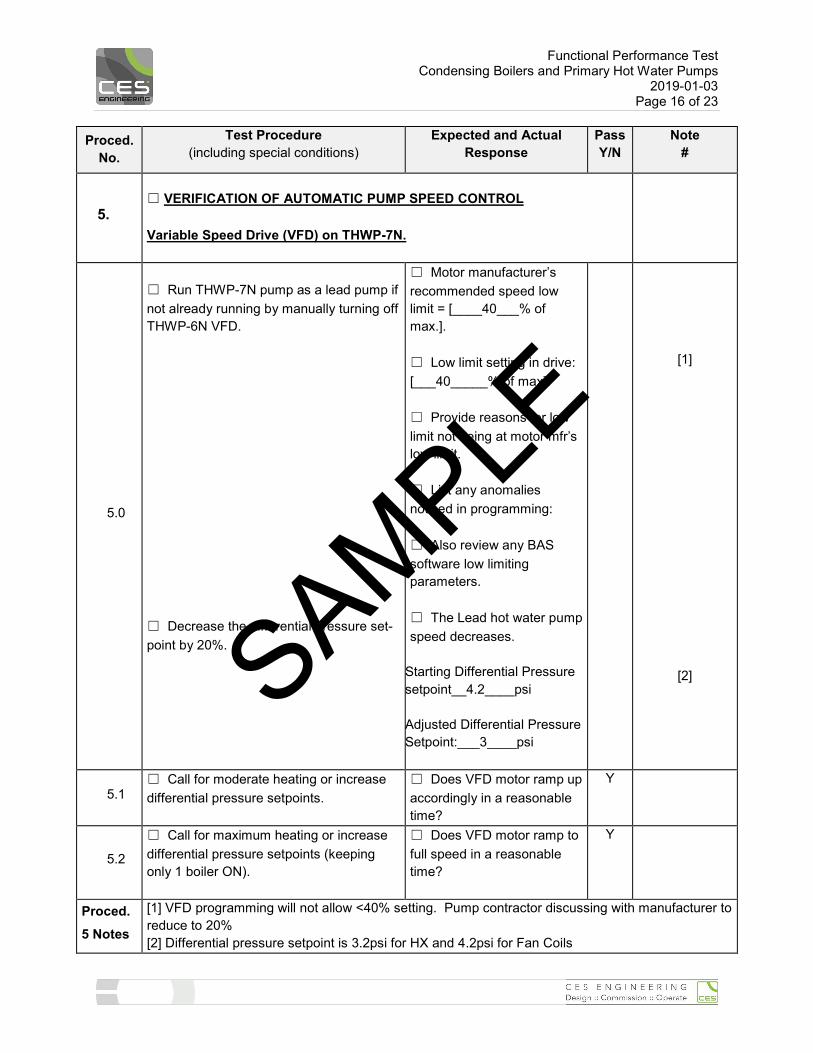
5. ☐ VERIFICATION OF AUTOMATIC PUMP SPEED CONTROL Variable Speed Drive (VFD) on THWP-7N.
5.0
☐ Run THWP-7N pump as a lead pump if not already running by manually turning off THWP-6N VFD. ☐ Decrease the differential pressure set-point by 20%.
☐ Motor manufacturer’s recommended speed low limit = [____40___% of max.]. ☐ Low limit setting in drive: [___40_____% of max]. ☐ Provide reasons for low limit not being at motor mfr’s low limit. ☐ List any anomalies noticed in programming: ☐ Also review any BAS software low limiting parameters. ☐ The Lead hot water pump speed decreases.
Starting Differential Pressure setpoint__4.2____psi Adjusted Differential Pressure Setpoint:___3____psi
[1]
[2]
5.1 ☐ Call for moderate heating or increase differential pressure setpoints.
☐ Does VFD motor ramp up accordingly in a reasonable time?
Y
5.2
☐ Call for maximum heating or increase differential pressure setpoints (keeping only 1 boiler ON).
☐ Does VFD motor ramp to full speed in a reasonable time?
Y
Proced. 5 Notes
[1] VFD programming will not allow <40% setting. Pump contractor discussing with manufacturer to reduce to 20% [2] Differential pressure setpoint is 3.2psi for HX and 4.2psi for Fan Coils
SAMPLE

Functional Performance Test Condensing Boilers and Primary Hot Water Pumps
2019-01-03 Page 17 of 23
Proced. No.
Test Procedure (including special conditions)
Expected and Actual Response
Pass Y/N
Note #
6. ☐ VERIFICATION OF AUTOMATIC PUMP SPEED CONTROL Variable Speed Drive (VFD) on THWP-8N.
6.0.
☐ Run THWP-8N pump as a lead pump if not already running by manually turning off THWP-9N VFD. ☐ Decrease the differential pressure set-point by 20%.
☐ Motor manufacturer’s recommended speed low limit = [___40_____% of max.]. ☐ Low limit setting in drive: [_____40___% of max]. ☐ Provide reasons for low limit not being at motor mfr’s low limit. ☐ List any anomalies noticed in programming: ☐ Also review any BAS software low limiting parameters. ☐ The Lead hot water pump speed decreases.
Starting Differential Pressure setpoint__3.2____psi Adjusted Differential Pressure Setpoint:___2____psi
-
Y
[1]
[2]I
6.1. ☐ Call for moderate heating or increase differential pressure setpoints.
☐ Does VFD motor ramp up accordingly in a reasonable time?
Y
6.2.
☐ Call for maximum heating or increase differential pressure setpoints (keeping only 1 boiler ON).
☐ Does VFD motor ramp to full speed in a reasonable time?
Y
Proced. 6 Notes
[1] VFD programming will not allow <40% setting. Pump contractor discussing with manufacturer to reduce to 20% [2] Differential pressure setpoint is 3.2psi for HX and 4.2psi for Fan Coils
SAMPLE
Functional Performance Test Condensing Boilers and Primary Hot Water Pumps
2019-01-03 Page 18 of 23
Proced. No.
Test Procedure (including special conditions)
Expected and Actual Response
Pass Y/N
Note #
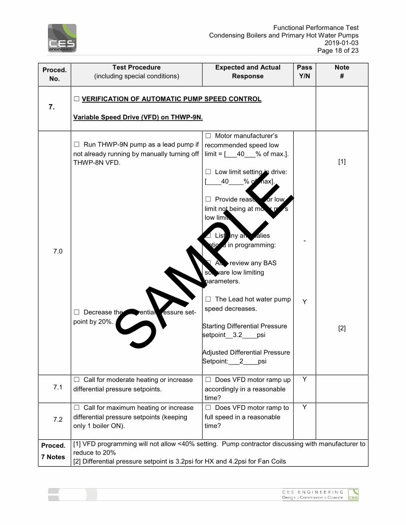
7. ☐ VERIFICATION OF AUTOMATIC PUMP SPEED CONTROL Variable Speed Drive (VFD) on THWP-9N.
7.0
☐ Run THWP-9N pump as a lead pump if not already running by manually turning off THWP-8N VFD. ☐ Decrease the differential pressure set-point by 20%.
☐ Motor manufacturer’s recommended speed low limit = [___40___% of max.]. ☐ Low limit setting in drive: [____40____% of max]. ☐ Provide reasons for low limit not being at motor mfr’s low limit. ☐ List any anomalies noticed in programming: ☐ Also review any BAS software low limiting parameters. ☐ The Lead hot water pump speed decreases.
Starting Differential Pressure setpoint__3.2____psi Adjusted Differential Pressure Setpoint:___2____psi
-
Y
[1]
[2]
7.1 ☐ Call for moderate heating or increase differential pressure setpoints.
☐ Does VFD motor ramp up accordingly in a reasonable time?
Y
7.2
☐ Call for maximum heating or increase differential pressure setpoints (keeping only 1 boiler ON).
☐ Does VFD motor ramp to full speed in a reasonable time?
Y
Proced. 7 Notes
[1] VFD programming will not allow <40% setting. Pump contractor discussing with manufacturer to reduce to 20% [2] Differential pressure setpoint is 3.2psi for HX and 4.2psi for Fan Coils
SAMPLE
Functional Performance Test Condensing Boilers and Primary Hot Water Pumps
2019-01-03 Page 19 of 23
Proced. No.
Test Procedure (including special conditions)
Expected and Actual Response
Pass Y/N
Note #
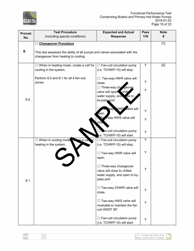
8.
☐ Changeover Procedure This test assesses the ability of all pumps and valves associated with the changeover from heating to cooling.
[1]
8.0.
☐ When in heating mode, create a call for cooling in the system. Perform 8.0 and 8.1 for all 4 fan-coil zones.
☐ Fan-coil circulation pump (i.e. TCHWP-10) will stop. ☐ Two-way HWR valve will close. ☐ Three-way changeover valve will open to chilled water supply, and close to by-pass port. ☐ Two-way CHWR valve will open. ☐Two-way HWS valve will close. ☐ Fan-coil circulation pump (i.e. TCHWP-10) will start.
Y
Y
Y
Y
Y
Y
[2]
8.1.
☐ When in cooling mode, create a call for heating in the system.
☐ Fan-coil circulation pump (i.e. TCHWP-10) will stop. ☐ Two-way HWR valve will open. ☐ Three-way changeover valve will close to chilled water supply, and open to by-pass port. ☐ Two-way CHWR valve will close. ☐ Two-way HWS valve will modulate to maintain the fan coil HWST SP. ☐ Fan-coil circulation pump (i.e. TCHWP-10) will start.
Y
Y
Y
Y
Y
Y
SAMPLE
Functional Performance Test Condensing Boilers and Primary Hot Water Pumps
2019-01-03 Page 20 of 23
Proced. No.
Test Procedure (including special conditions)
Expected and Actual Response
Pass Y/N
Note #
Proced. 8 Notes
[1] See Appendix for trend logs of system changeover from heating to cooling. [2] There are some issues regarding the time required to switch over. Currently there are protections in place to prevent hot water from entering/damaging the chillers. This means that the system must dissipate enough heat in the loop before the valves to the chillers are opened.
SAMPLE
Functional Performance Test Condensing Boilers and Primary Hot Water Pumps
2019-01-03 Page 21 of 23
Proced. No.
Test Procedure (including special conditions)
Expected and Actual Response
Pass Y/N
Note #
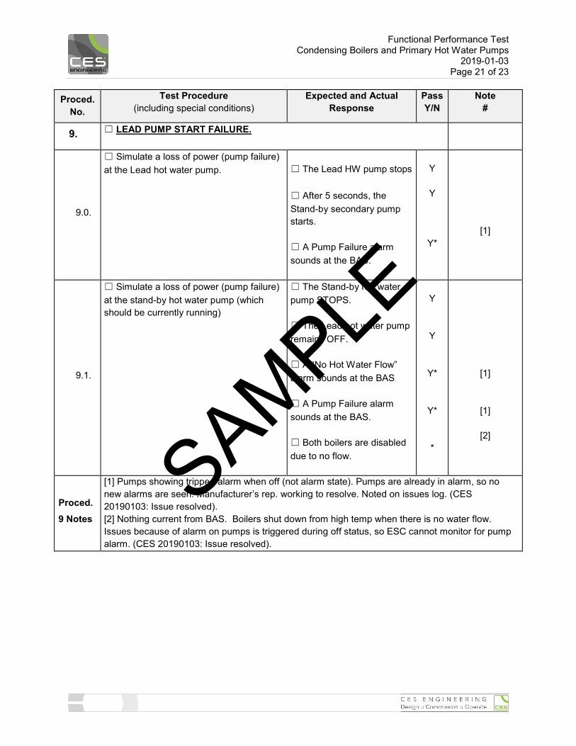
9. ☐ LEAD PUMP START FAILURE.
9.0.
☐ Simulate a loss of power (pump failure) at the Lead hot water pump.
☐ The Lead HW pump stops ☐ After 5 seconds, the Stand-by secondary pump starts. ☐ A Pump Failure alarm sounds at the BAS.
Y
Y
Y*
[1]
9.1.
☐ Simulate a loss of power (pump failure) at the stand-by hot water pump (which should be currently running)
☐ The Stand-by hot water pump STOPS. ☐ The Lead hot water pump remains OFF. ☐ A “No Hot Water Flow” alarm sounds at the BAS ☐ A Pump Failure alarm sounds at the BAS. ☐ Both boilers are disabled due to no flow.
Y
Y
Y*
Y* *
[1]
[1]
[2]
Proced. 9 Notes
[1] Pumps showing tripped alarm when off (not alarm state). Pumps are already in alarm, so no new alarms are seen. Manufacturer’s rep. working to resolve. Noted on issues log. (CES 20190103: Issue resolved). [2] Nothing current from BAS. Boilers shut down from high temp when there is no water flow. Issues because of alarm on pumps is triggered during off status, so ESC cannot monitor for pump alarm. (CES 20190103: Issue resolved).
SAMPLE
Functional Performance Test Condensing Boilers and Primary Hot Water Pumps
2019-01-03 Page 22 of 23
Proced. No.
Test Procedure (including special conditions)
Expected and Actual Response
Pass Y/N
Note #
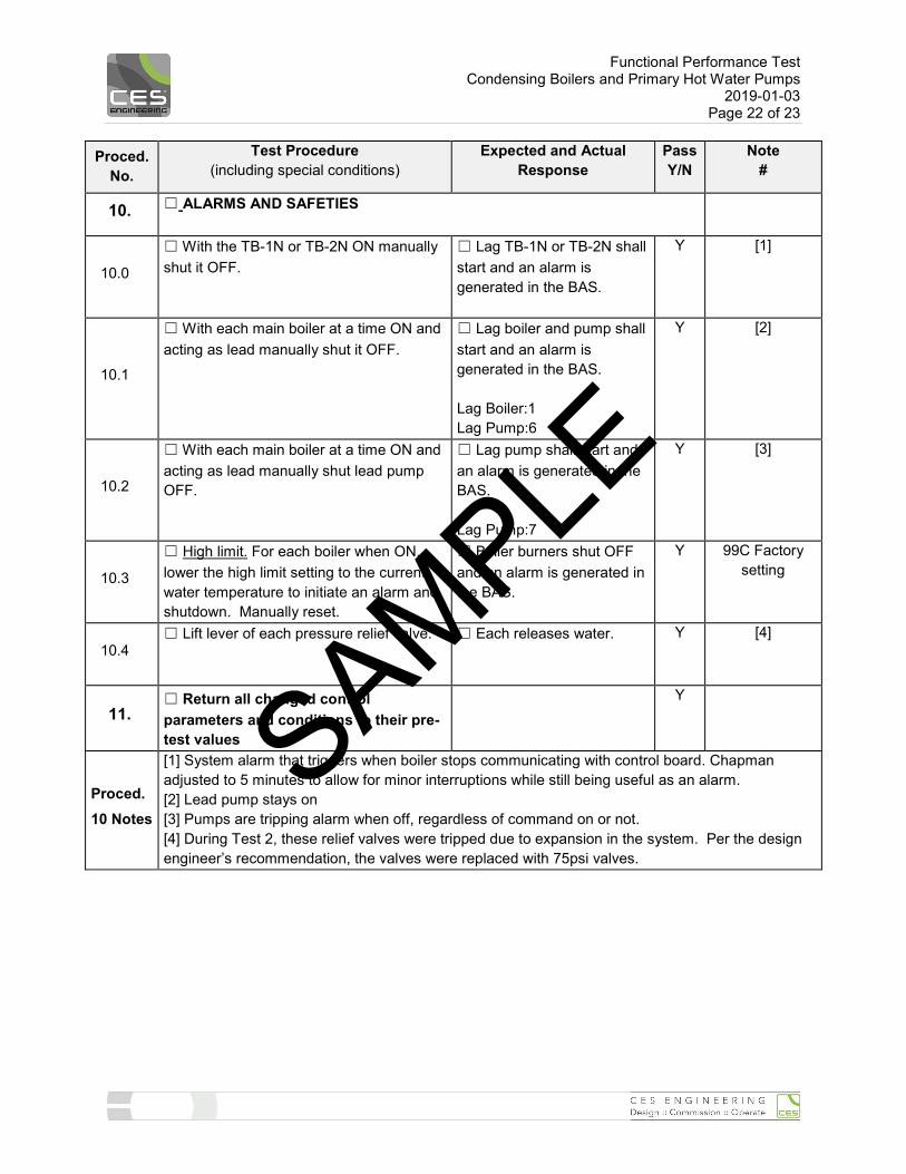
10. ☐ ALARMS AND SAFETIES
10.0
☐ With the TB-1N or TB-2N ON manually shut it OFF.
☐ Lag TB-1N or TB-2N shall start and an alarm is generated in the BAS.
Y [1]
10.1
☐ With each main boiler at a time ON and acting as lead manually shut it OFF.
☐ Lag boiler and pump shall start and an alarm is generated in the BAS. Lag Boiler:1 Lag Pump:6
Y [2]
10.2
☐ With each main boiler at a time ON and acting as lead manually shut lead pump OFF.
☐ Lag pump shall start and an alarm is generated in the BAS. Lag Pump:7
Y [3]
10.3
☐ High limit. For each boiler when ON, lower the high limit setting to the current water temperature to initiate an alarm and shutdown. Manually reset.
☐ Boiler burners shut OFF and an alarm is generated in the BAS.
Y 99C Factory setting
10.4 ☐ Lift lever of each pressure relief valve.
☐ Each releases water. Y [4]
11. ☐ Return all changed control parameters and conditions to their pre-test values
Y
Proced. 10 Notes
[1] System alarm that triggers when boiler stops communicating with control board. Chapman adjusted to 5 minutes to allow for minor interruptions while still being useful as an alarm. [2] Lead pump stays on [3] Pumps are tripping alarm when off, regardless of command on or not. [4] During Test 2, these relief valves were tripped due to expansion in the system. Per the design engineer’s recommendation, the valves were replaced with 75psi valves.
SAMPLE
Functional Performance Test Condensing Boilers and Primary Hot Water Pumps
2019-01-03 Page 23 of 23
10. APPENDIX - Sequences of Operation and System Schematics The following to be included as an appendix to this Test Report
• As-Built Control Sequences of Operation NOTE: Controls As Builts are included in the Final O&M Manual.
• As-Built System Schematic
NOTE: System Schematic As Builts will be included in the Final O&M Manual.
• Trend Logs: See following pages.
SAMPLE
12
Appendix 3H - Commissioning (Burnaby Hospital Phase 1 – Redevelopment Project)
June 12th, 2020
5. FF&E Handover Form SAMPLE
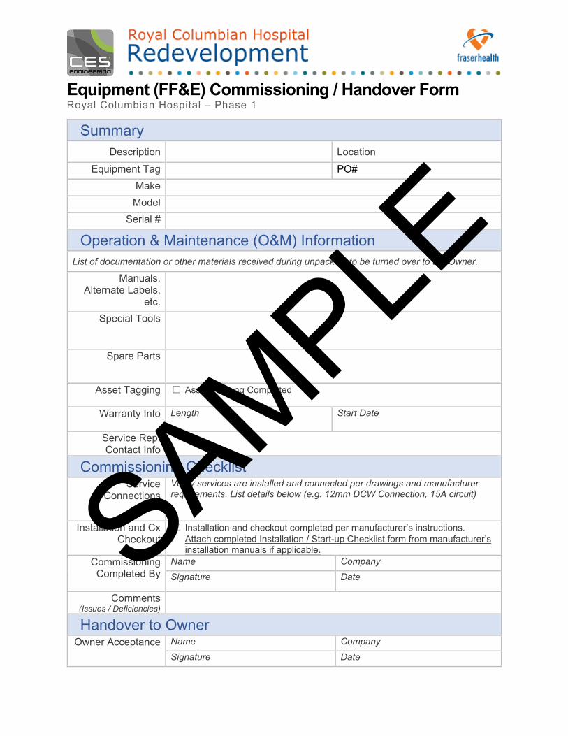
Equipment (FF&E) Commissioning / Handover Form Royal Columbian Hospital – Phase 1
Summary Description Location
Equipment Tag PO# Make
Model Serial #
Operation & Maintenance (O&M) Information List of documentation or other materials received during unpacking to be turned over to the Owner.
Manuals, Alternate Labels,
etc. Special Tools
Spare Parts
Asset Tagging ☐ Asset Tagging Completed
Warranty Info Length Start Date
Service Rep. Contact Info
Commissioning Checklist Service
Connections Verify services are installed and connected per drawings and manufacturer requirements. List details below (e.g. 12mm DCW Connection, 15A circuit)
Installation and Cx Checkout
☐ Installation and checkout completed per manufacturer’s instructions.Attach completed Installation / Start-up Checklist form from manufacturer’sinstallation manuals if applicable.
Commissioning Completed By
Name Company
Signature Date
Comments (Issues / Deficiencies)
Handover to Owner Owner Acceptance Name Company
Signature Date
SAMPLE

14
Appendix 3H - Commissioning (Burnaby Hospital Phase 1 – Redevelopment Project)
June 12th, 2020
6. Training Summary SAMPLE
This document is provided as a representative sample to establish a standard level of detail and rigor.
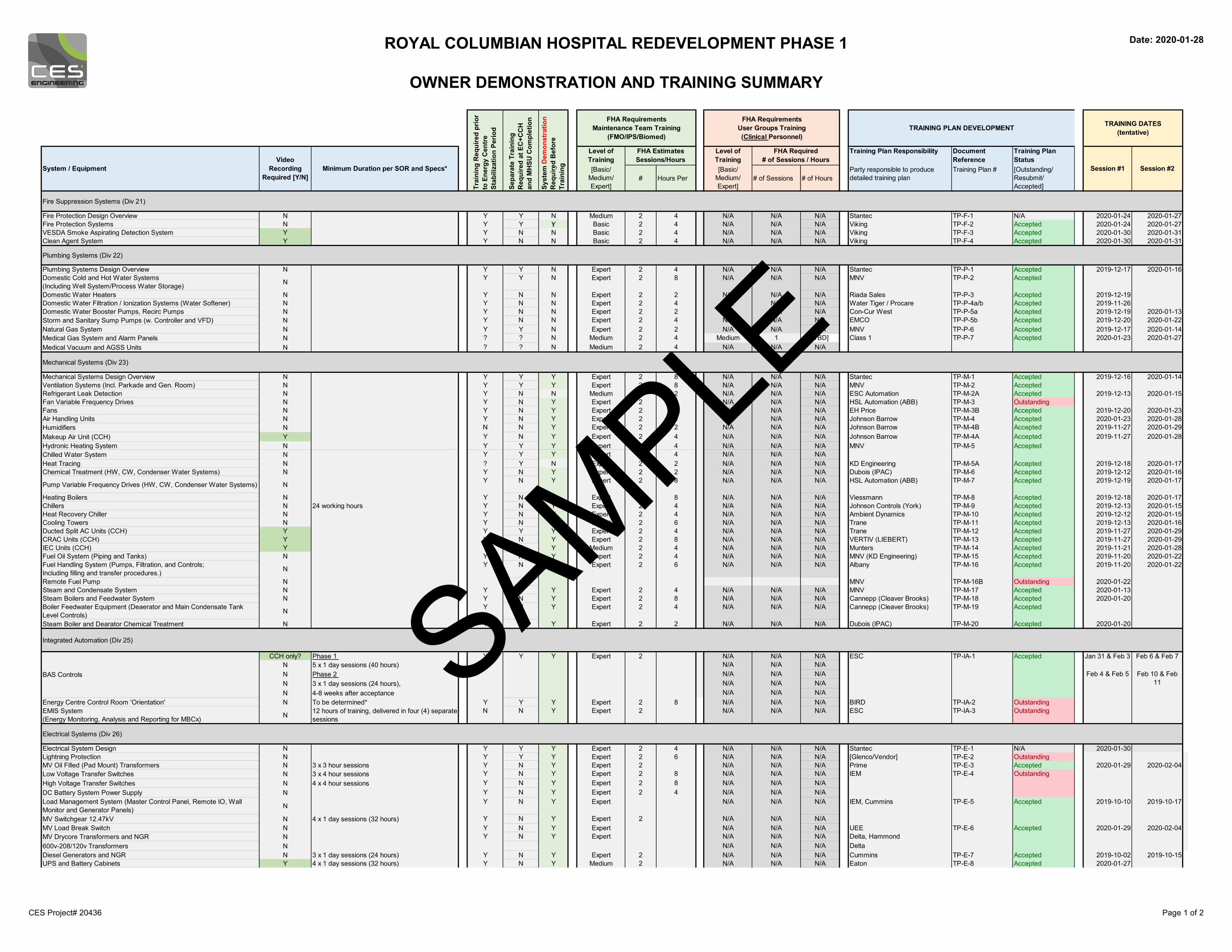
ROYAL COLUMBIAN HOSPITAL REDEVELOPMENT PHASE 1
OWNER DEMONSTRATION AND TRAINING SUMMARY
Date: 2020-01-28
Level of Training
Level of Training
Training Plan Responsibility Document Reference
Training Plan Status
[Basic/Medium/Expert]
# Hours Per[Basic/
Medium/Expert]
# of Sessions # of HoursParty responsible to produce detailed training plan
Training Plan # [Outstanding/Resubmit/Accepted]
Fire Suppression Systems (Div 21)
Fire Protection Design Overview N Y Y N Medium 2 4 N/A N/A N/A Stantec TP-F-1 N/A 2020-01-24 2020-01-27Fire Protection Systems N Y Y Y Basic 2 4 N/A N/A N/A Viking TP-F-2 Accepted 2020-01-24 2020-01-27VESDA Smoke Aspirating Detection System Y Y N N Basic 2 4 N/A N/A N/A Viking TP-F-3 Accepted 2020-01-30 2020-01-31Clean Agent System Y Y N N Basic 2 4 N/A N/A N/A Viking TP-F-4 Accepted 2020-01-30 2020-01-31
Plumbing Systems (Div 22)
Plumbing Systems Design Overview N Y Y N Expert 2 4 N/A N/A N/A Stantec TP-P-1 Accepted 2019-12-17 2020-01-16Domestic Cold and Hot Water Systems (Including Well System/Process Water Storage) N Y Y N Expert 2 8 N/A N/A N/A MNV TP-P-2 Accepted
Domestic Water Heaters N Y N N Expert 2 2 N/A N/A N/A Riada Sales TP-P-3 Accepted 2019-12-19Domestic Water Filtration / Ionization Systems (Water Softener) N Y N N Expert 2 4 N/A N/A N/A Water Tiger / Procare TP-P-4a/b Accepted 2019-11-26Domestic Water Booster Pumps, Recirc Pumps N Y N N Expert 2 2 N/A N/A N/A Con-Cur West TP-P-5a Accepted 2019-12-19 2020-01-13Storm and Sanitary Sump Pumps (w. Controller and VFD) N Y N N Expert 2 4 N/A N/A N/A EMCO TP-P-5b Accepted 2019-12-20 2020-01-22Natural Gas System N Y Y N Expert 2 2 N/A N/A N/A MNV TP-P-6 Accepted 2019-12-17 2020-01-14Medical Gas System and Alarm Panels N ? ? N Medium 2 4 Medium 1 [TBD]Medical Vacuum and AGSS Units N ? ? N Medium 2 4 N/A N/A N/A
Mechanical Systems (Div 23)
Mechanical Systems Design Overview N Y Y Y Expert 2 8 N/A N/A N/A Stantec TP-M-1 Accepted 2019-12-16 2020-01-14Ventilation Systems (Incl. Parkade and Gen. Room) N Y Y Y Expert 2 8 N/A N/A N/A MNV TP-M-2 AcceptedRefrigerant Leak Detection N Y N N Medium 2 2 N/A N/A N/A ESC Automation TP-M-2A Accepted 2019-12-13 2020-01-15Fan Variable Frequency Drives N Y N Y Expert 2 8 N/A N/A N/A HSL Automation (ABB) TP-M-3 OutstandingFans N Y N Y Expert 2 2 N/A N/A N/A EH Price TP-M-3B Accepted 2019-12-20 2020-01-23Air Handling Units N Y N Y Expert 2 4 N/A N/A N/A Johnson Barrow TP-M-4 Accepted 2020-01-23 2020-01-28Humidifiers N N N Y Expert 2 2 N/A N/A N/A Johnson Barrow TP-M-4B Accepted 2019-11-27 2020-01-29Makeup Air Unit (CCH) Y Y N Y Expert 2 4 N/A N/A N/A Johnson Barrow TP-M-4A Accepted 2019-11-27 2020-01-28Hydronic Heating System N Y Y Y Expert 2 4 N/A N/A N/AChilled Water System N Y Y Y Expert 2 4 N/A N/A N/AHeat Tracing N ? Y N Expert 2 2 N/A N/A N/A KD Engineering TP-M-5A Accepted 2019-12-18 2020-01-17Chemical Treatment (HW, CW, Condenser Water Systems) N Y N Y Expert 2 2 N/A N/A N/A Dubois (IPAC) TP-M-6 Accepted 2019-12-12 2020-01-16
Pump Variable Frequency Drives (HW, CW, Condenser Water Systems) N Y N Y Expert 2 8 N/A N/A N/A HSL Automation (ABB) TP-M-7 Accepted 2019-12-19 2020-01-17
Heating Boilers N Y N Y Expert 2 8 N/A N/A N/A Viessmann TP-M-8 Accepted 2019-12-18 2020-01-17Chillers N 24 working hours Y N Y Expert 2 4 N/A N/A N/A Johnson Controls (York) TP-M-9 Accepted 2019-12-13 2020-01-15Heat Recovery Chiller N Y N Y Expert 2 4 N/A N/A N/A Ambient Dynamics TP-M-10 Accepted 2019-12-12 2020-01-15Cooling Towers N Y N Y Expert 2 6 N/A N/A N/A Trane TP-M-11 Accepted 2019-12-13 2020-01-16Ducted Split AC Units (CCH) Y Y Y Y Expert 2 4 N/A N/A N/A Trane TP-M-12 Accepted 2019-11-27 2020-01-29CRAC Units (CCH) Y Y N Y Expert 2 8 N/A N/A N/A VERTIV (LIEBERT) TP-M-13 Accepted 2019-11-27 2020-01-29IEC Units (CCH) Y Y N Y Medium 2 4 N/A N/A N/A Munters TP-M-14 Accepted 2019-11-21 2020-01-28Fuel Oil System (Piping and Tanks) N Y N Y Expert 2 4 N/A N/A N/A MNV (KD Engineering) TP-M-15 Accepted 2019-11-20 2020-01-22Fuel Handling System (Pumps, Filtration, and Controls;Including filling and transfer procedures.) N Y N Y Expert 2 6 N/A N/A N/A Albany TP-M-16 Accepted 2019-11-20 2020-01-22
Remote Fuel Pump N MNV TP-M-16B Outstanding 2020-01-22Steam and Condensate System N Y N Y Expert 2 4 N/A N/A N/A MNV TP-M-17 Accepted 2020-01-13Steam Boilers and Feedwater System N Y N Y Expert 2 8 N/A N/A N/A Cannepp (Cleaver Brooks) TP-M-18 Accepted 2020-01-20Boiler Feedwater Equipment (Deaerator and Main Condensate Tank Level Controls) N Y N Y Expert 2 4 N/A N/A N/A Cannepp (Cleaver Brooks) TP-M-19 Accepted
Steam Boiler and Dearator Chemical Treatment N Y N Y Expert 2 2 N/A N/A N/A Dubois (IPAC) TP-M-20 Accepted 2020-01-20
Integrated Automation (Div 25)
CCH only? Phase 1 N/A N/A N/AN 5 x 1 day sessions (40 hours) N/A N/A N/AN Phase 2 N/A N/A N/AN 3 x 1 day sessions (24 hours), N/A N/A N/AN 4-8 weeks after acceptance N/A N/A N/A
Energy Centre Control Room 'Orientation' N To be determined* Y Y Y Expert 2 8 N/A N/A N/A BIRD TP-IA-2 OutstandingEMIS System (Energy Monitoring, Analysis and Reporting for MBCx) N 12 hours of training, delivered in four (4) separate
sessionsN N Y Expert 2 N/A N/A N/A ESC TP-IA-3 Outstanding
Electrical Systems (Div 26)
Electrical System Design N Y Y Y Expert 2 4 N/A N/A N/A Stantec TP-E-1 N/A 2020-01-30Lightning Protection N Y Y Y Expert 2 6 N/A N/A N/A [Glenco/Vendor] TP-E-2 OutstandingMV Oil Filled (Pad Mount) Transformers N 3 x 3 hour sessions Y N Y Expert 2 N/A N/A N/A Prime TP-E-3 Accepted 2020-01-29 2020-02-04Low Voltage Transfer Switches N 3 x 4 hour sessions Y N Y Expert 2 8 N/A N/A N/AHigh Voltage Transfer Switches N 4 x 4 hour sessions Y N Y Expert 2 8 N/A N/A N/ADC Battery System Power Supply N Y N Y Expert 2 4 N/A N/A N/ALoad Management System (Master Control Panel, Remote IO, Wall Monitor and Generator Panels) N Y N Y Expert N/A N/A N/A
MV Switchgear 12.47kV N 4 x 1 day sessions (32 hours) Y N Y Expert 2 N/A N/A N/AMV Load Break Switch N Y N Y Expert N/A N/A N/A UEEMV Drycore Transformers and NGR N Y N Y Expert N/A N/A N/A Delta, Hammond600v-208/120v Transformers N N/A N/A N/A DeltaDiesel Generators and NGR N 3 x 1 day sessions (24 hours) Y N Y Expert 2 N/A N/A N/A Cummins TP-E-7 Accepted 2019-10-02 2019-10-15UPS and Battery Cabinets Y 4 x 1 day sessions (32 hours) Y N Y Medium 2 N/A N/A N/A Eaton TP-E-8 Accepted 2020-01-27
Accepted
TP-E-6
Jan 31 & Feb 3 Feb 6 & Feb 7
Feb 4 & Feb 5 Feb 10 & Feb 11
2020-02-042020-01-29
TP-P-7 Accepted
System / Equipment
BAS Controls
TP-M-5MNV
Video Recording
Required [Y/N]Minimum Duration per SOR and Specs*
ESC TP-IA-1
Class 1
TRAINING PLAN DEVELOPMENT
FHA Required# of Sessions / Hours
FHA RequirementsUser Groups Training (Clinical Personnel)
FHA RequirementsMaintenance Team Training
(FMO/IPS/Biomed)
FHA EstimatesSessions/Hours
Expert
Syst
em D
emon
stra
tion
Req
uire
d B
efor
e Tr
aini
ng
Trai
ning
Req
uire
d pr
ior
to E
nerg
y C
entr
e St
abili
zatio
n Pe
riod
Accepted
Sepa
rate
Tra
inin
g R
equi
red
at E
C+C
CH
an
d M
HSU
Com
plet
ion
2YY
AcceptedTP-E-5IEM, Cummins
IEM TP-E-4 Outstanding
Accepted
Y
TRAINING DATES(tentative)
Session #1 Session #2
2019-10-172019-10-10
2020-01-23 2020-01-27
CES Project# 20436 Page 1 of 2
SAMPLE
ROYAL COLUMBIAN HOSPITAL REDEVELOPMENT PHASE 1
OWNER DEMONSTRATION AND TRAINING SUMMARY
Date: 2020-01-28
Level of Training
Level of Training
Training Plan Responsibility Document Reference
Training Plan Status
[Basic/Medium/Expert]
# Hours Per[Basic/
Medium/Expert]
# of Sessions # of HoursParty responsible to produce detailed training plan
Training Plan # [Outstanding/Resubmit/Accepted]
System / EquipmentVideo
RecordingRequired [Y/N]
Minimum Duration per SOR and Specs*
TRAINING PLAN DEVELOPMENT
FHA Required# of Sessions / Hours
FHA RequirementsUser Groups Training (Clinical Personnel)
FHA RequirementsMaintenance Team Training
(FMO/IPS/Biomed)
FHA EstimatesSessions/Hours
Syst
em D
emon
stra
tion
Req
uire
d B
efor
e Tr
aini
ng
Trai
ning
Req
uire
d pr
ior
to E
nerg
y C
entr
e St
abili
zatio
n Pe
riod
Sepa
rate
Tra
inin
g R
equi
red
at E
C+C
CH
an
d M
HSU
Com
plet
ion TRAINING DATES
(tentative)
Session #1 Session #2
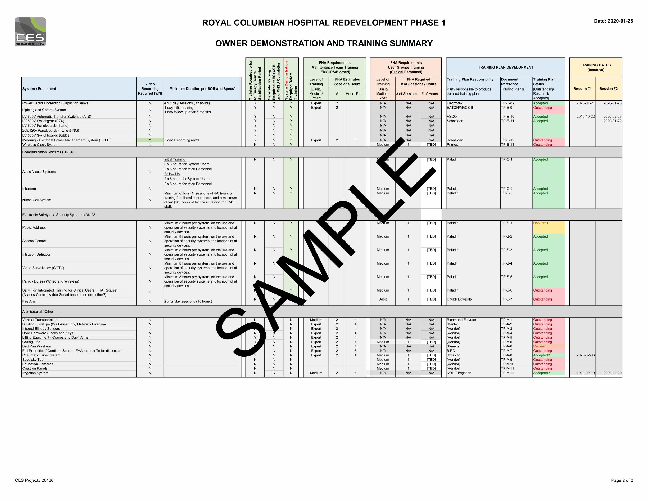
Power Factor Correction (Capacitor Banks) N 4 x 1 day sessions (32 hours) Y Y Y Expert 2 N/A N/A N/A Electrotek TP-E-8A Accepted 2020-01-21 2020-01-28
Lighting and Control System N 1 day initial training1 day follow up after 6 months
Y Y Y Expert 2 N/A N/A N/A EATON/MACS-II TP-E-9 Outstanding
LV 600V Automatic Transfer Switches (ATS) N Y N Y N/A N/A N/A ASCO TP-E-10 Accepted 2019-10-22 2020-02-06LV 600V Switchgear (PZ4) N Y N Y N/A N/A N/ALV 600V Panelboards (I-Line) N Y N Y N/A N/A N/A208/120v Panelboards (I-Line & NQ) N Y N Y N/A N/A N/ALV 600V Switchboards (QED) N Y N Y N/A N/A N/AMetering - Electrical Power Management System (EPMS) Y Video Recording req'd Y N Y Expert 2 8 N/A N/A N/A Schneider TP-E-12 OutstandingWireless Clock System N N N Y Medium 1 [TBD] Primex TP-E-13 Outstanding
Communication Systems (Div 26)
Initial Training 3 x 6 hours for System Users2 x 6 hours for Mtce PersonnelFollow Up2 x 6 hours for System Users2 x 6 hours for Mtce Personnel
Intercom N N N Y Medium 1 [TBD] Paladin TP-C-2 Accepted
Nurse Call System N
Minimum of four (4) sessions of 4-6 hours of training for clinical super-users, and a minimum of ten (10) hours of technical training for FMO staff.
N N Y Medium 1 [TBD] Paladin TP-C-3 Accepted
Electronic Safety and Security Systems (Div 28)
Public Address NMinimum 8 hours per system, on the use and operation of security systems and location of all security devices.
N N Y Medium 1 [TBD] Paladin TP-S-1 Resubmit
Access Control NMinimum 8 hours per system, on the use and operation of security systems and location of all security devices.
N N Y Medium 1 [TBD] Paladin TP-S-2 Accepted
Intrusion Detection NMinimum 8 hours per system, on the use and operation of security systems and location of all security devices.
N N Y Medium 1 [TBD] Paladin TP-S-3 Accepted
Video Surveillance (CCTV) NMinimum 8 hours per system, on the use and operation of security systems and location of all security devices.
N N Y Medium 1 [TBD] Paladin TP-S-4 Accepted
Panic / Duress (Wired and Wireless) NMinimum 8 hours per system, on the use and operation of security systems and location of all security devices.
N N Y Medium 1 [TBD] Paladin TP-S-5 Accepted
Sally Port Integrated Training for Clinical Users [FHA Request](Access Control, Video Surveillance, Intercom, other?) N N N Y Medium 1 [TBD] Paladin TP-S-6 Outstanding
Fire Alarm N 2 x full day sessions (16 hours) N N N Basic 1 [TBD] Chubb Edwards TP-S-7 Outstanding
Architectural / Other
Vertical Transportation N N N N Medium 2 4 N/A N/A N/A Richmond Elevator TP-A-1 OutstandingBuilding Envelope (Wall Assembly, Materials Overview) N N N N Expert 2 4 N/A N/A N/A Stantec TP-A-2 OutstandingIntegral Blinds / Sensors N N N N Expert 2 4 N/A N/A N/A [Vendor] TP-A-3 OutstandingDoor Hardware (Locks and Keys) N N N N Expert 2 4 N/A N/A N/A [Vendor] TP-A-4 OutstandingLifting Equipment - Cranes and Davit Arms N Y N N Expert 2 4 N/A N/A N/A [Vendor] TP-A-5 OutstandingCeiling Lifts N Y N N Expert 2 4 Medium 1 [TBD] [Vendor] TP-A-5 OutstandingBed Pan Washers N N N N Expert 2 4 N/A N/A N/A Stevens TP-A-6 ReviewFall Protection / Confined Space - FHA request To be discussed N ? N N Expert 2 8 N/A N/A N/A BIRD TP-A-7 OutstandingPneumatic Tube System N ? N N Expert 2 4 Medium 1 [TBD] Swisslog TP-A-8 Accepted? 2020-02-06Specialty Tub N N N N Medium 1 [TBD] [Vendor] TP-A-9 OutstandingEducation Cameras N N N N Medium 1 [TBD] [Vendor] TP-A-10 OutstandingCrestron Panels N N N N Medium 1 [TBD] [Vendor] TP-A-11 OutstandingIrrigation System N N N N Medium 2 4 N/A N/A N/A KORE Irrigation TP-A-12 Accepted? 2020-02-19 2020-02-20
TP-E-11 Accepted
Audio Visual Systems
N Y
N
MediumN 1 [TBD] Paladin TP-C-1 Accepted
Schneider 2020-01-22
CES Project# 20436 Page 2 of 2
SAMPLE
16
Appendix 3H - Commissioning (Burnaby Hospital Phase 1 – Redevelopment Project)
June 12th, 2020
7. Training Plan SAMPLE This document is provided as a representative sample to establish a standard level of detail and rigor.
Page 1 of 7
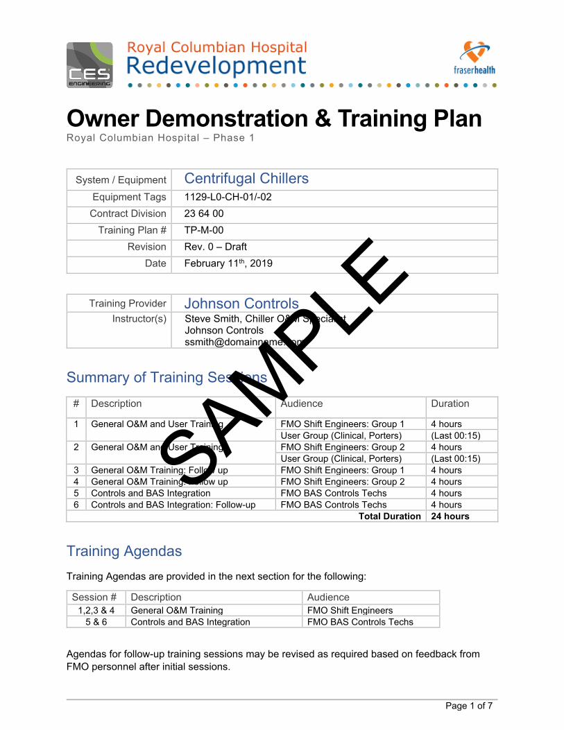
Owner Demonstration & Training Plan Royal Columbian Hospital – Phase 1
System / Equipment Centrifugal Chillers
Equipment Tags 1129-L0-CH-01/-02 Contract Division 23 64 00
Training Plan # TP-M-00 Revision Rev. 0 – Draft
Date February 11th, 2019
Training Provider Johnson Controls Instructor(s)
Steve Smith, Chiller O&M Specialist Johnson Controls [email protected]
Summary of Training Sessions # Description Audience Duration
1 General O&M and User Training FMO Shift Engineers: Group 1 4 hours User Group (Clinical, Porters) (Last 00:15)
2 General O&M and User Training FMO Shift Engineers: Group 2 4 hours User Group (Clinical, Porters) (Last 00:15)
3 General O&M Training: Follow up FMO Shift Engineers: Group 1 4 hours 4 General O&M Training: Follow up FMO Shift Engineers: Group 2 4 hours 5 Controls and BAS Integration FMO BAS Controls Techs 4 hours 6 Controls and BAS Integration: Follow-up FMO BAS Controls Techs 4 hours
Total Duration 24 hours
Training Agendas Training Agendas are provided in the next section for the following:
Session # Description Audience 1,2,3 & 4 General O&M Training FMO Shift Engineers
5 & 6 Controls and BAS Integration FMO BAS Controls Techs
Agendas for follow-up training sessions may be revised as required based on feedback from FMO personnel after initial sessions.
SAMPLE
Owner Demonstration & Training Plan – Centrifugal Chillers Royal Columbian Hospital – Phase 1
Page 2 of 7
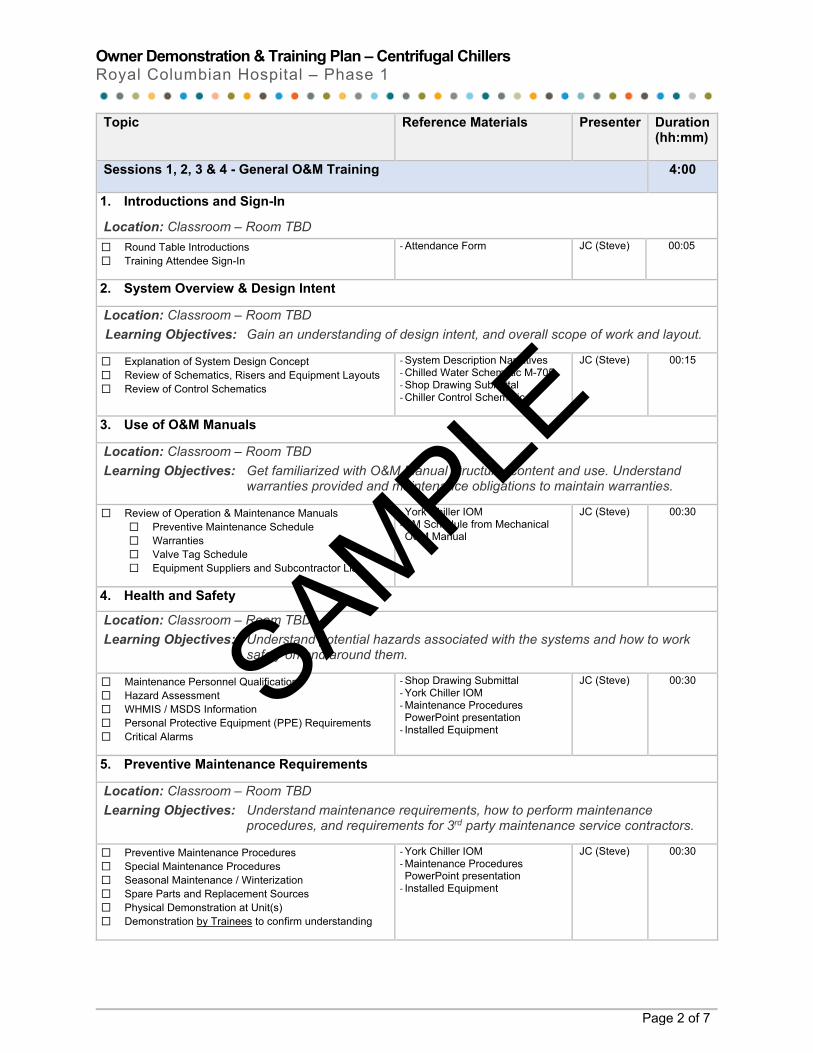
Topic Reference Materials Presenter Duration (hh:mm)
Sessions 1, 2, 3 & 4 - General O&M Training
4:00
1. Introductions and Sign-In
Location: Classroom – Room TBD ⬜ Round Table Introductions ⬜ Training Attendee Sign-In
- Attendance Form
JC (Steve) 00:05
2. System Overview & Design Intent
Location: Classroom – Room TBD Learning Objectives: Gain an understanding of design intent, and overall scope of work and layout.
⬜ Explanation of System Design Concept ⬜ Review of Schematics, Risers and Equipment Layouts ⬜ Review of Control Schematics
- System Description Narratives - Chilled Water Schematic M-705 - Shop Drawing Submittal - Chiller Control Schematic
JC (Steve) 00:15
3. Use of O&M Manuals
Location: Classroom – Room TBD Learning Objectives: Get familiarized with O&M Manual structure, content and use. Understand
warranties provided and maintenance obligations to maintain warranties.
⬜ Review of Operation & Maintenance Manuals ⬜ Preventive Maintenance Schedule ⬜ Warranties ⬜ Valve Tag Schedule ⬜ Equipment Suppliers and Subcontractor List
- York Chiller IOM - PM Schedule from Mechanical O&M Manual
JC (Steve) 00:30
4. Health and Safety
Location: Classroom – Room TBD Learning Objectives: Understand potential hazards associated with the systems and how to work
safely on and around them.
⬜ Maintenance Personnel Qualifications ⬜ Hazard Assessment ⬜ WHMIS / MSDS Information ⬜ Personal Protective Equipment (PPE) Requirements ⬜ Critical Alarms
- Shop Drawing Submittal - York Chiller IOM - Maintenance Procedures PowerPoint presentation
- Installed Equipment
JC (Steve) 00:30
5. Preventive Maintenance Requirements
Location: Classroom – Room TBD Learning Objectives: Understand maintenance requirements, how to perform maintenance
procedures, and requirements for 3rd party maintenance service contractors.
⬜ Preventive Maintenance Procedures ⬜ Special Maintenance Procedures ⬜ Seasonal Maintenance / Winterization ⬜ Spare Parts and Replacement Sources ⬜ Physical Demonstration at Unit(s) ⬜ Demonstration by Trainees to confirm understanding
- York Chiller IOM - Maintenance Procedures PowerPoint presentation
- Installed Equipment
JC (Steve) 00:30
SAMPLE
Owner Demonstration & Training Plan – Centrifugal Chillers Royal Columbian Hospital – Phase 1
Page 3 of 7
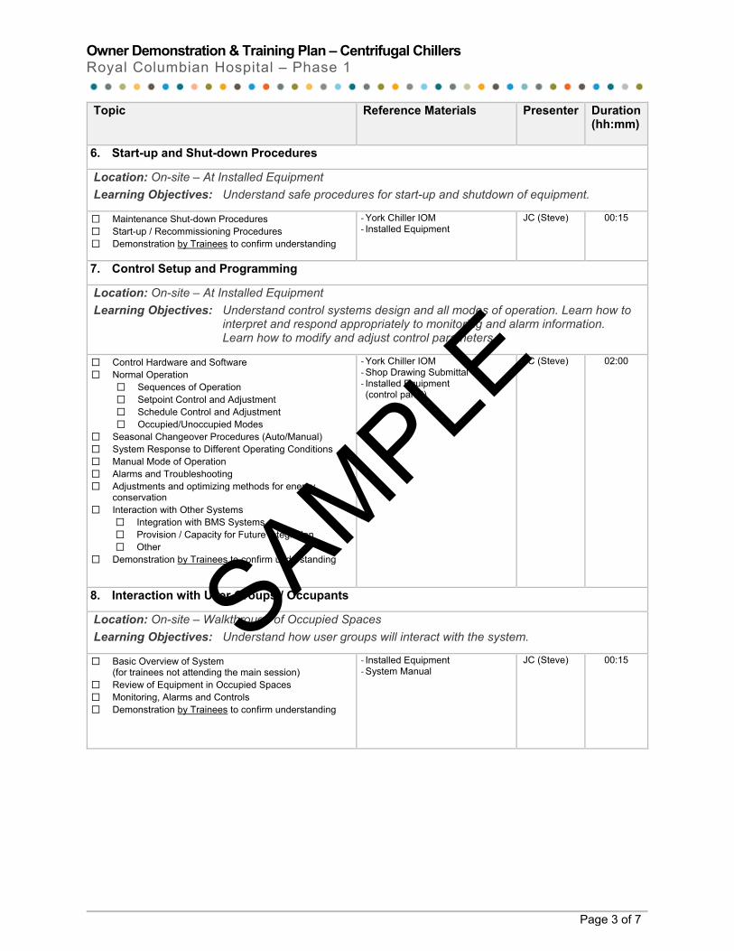
Topic Reference Materials Presenter Duration (hh:mm)
6. Start-up and Shut-down Procedures
Location: On-site – At Installed Equipment Learning Objectives: Understand safe procedures for start-up and shutdown of equipment.
⬜ Maintenance Shut-down Procedures ⬜ Start-up / Recommissioning Procedures ⬜ Demonstration by Trainees to confirm understanding
- York Chiller IOM - Installed Equipment
JC (Steve) 00:15
7. Control Setup and Programming
Location: On-site – At Installed Equipment Learning Objectives: Understand control systems design and all modes of operation. Learn how to
interpret and respond appropriately to monitoring and alarm information. Learn how to modify and adjust control parameters.
⬜ Control Hardware and Software ⬜ Normal Operation
⬜ Sequences of Operation ⬜ Setpoint Control and Adjustment ⬜ Schedule Control and Adjustment ⬜ Occupied/Unoccupied Modes
⬜ Seasonal Changeover Procedures (Auto/Manual) ⬜ System Response to Different Operating Conditions ⬜ Manual Mode of Operation ⬜ Alarms and Troubleshooting ⬜ Adjustments and optimizing methods for energy
conservation ⬜ Interaction with Other Systems
⬜ Integration with BMS Systems ⬜ Provision / Capacity for Future Integration ⬜ Other
⬜ Demonstration by Trainees to confirm understanding
- York Chiller IOM - Shop Drawing Submittal - Installed Equipment (control panel)
JC (Steve) 02:00
8. Interaction with User Groups / Occupants
Location: On-site – Walkthrough of Occupied Spaces Learning Objectives: Understand how user groups will interact with the system.
⬜ Basic Overview of System (for trainees not attending the main session)
⬜ Review of Equipment in Occupied Spaces ⬜ Monitoring, Alarms and Controls ⬜ Demonstration by Trainees to confirm understanding
- Installed Equipment - System Manual
JC (Steve) 00:15
SAMPLE
Owner Demonstration & Training Plan – Centrifugal Chillers Royal Columbian Hospital – Phase 1
Page 4 of 7
Topic Reference Materials Presenter Duration (hh:mm)
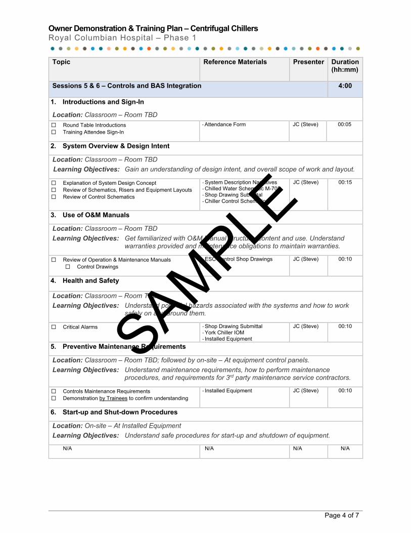
Sessions 5 & 6 – Controls and BAS Integration
4:00
1. Introductions and Sign-In
Location: Classroom – Room TBD ⬜ Round Table Introductions ⬜ Training Attendee Sign-In
- Attendance Form
JC (Steve) 00:05
2. System Overview & Design Intent
Location: Classroom – Room TBD Learning Objectives: Gain an understanding of design intent, and overall scope of work and layout.
⬜ Explanation of System Design Concept ⬜ Review of Schematics, Risers and Equipment Layouts ⬜ Review of Control Schematics
- System Description Narratives - Chilled Water Schematic M-705 - Shop Drawing Submittal - Chiller Control Schematic
JC (Steve) 00:15
3. Use of O&M Manuals
Location: Classroom – Room TBD Learning Objectives: Get familiarized with O&M Manual structure, content and use. Understand
warranties provided and maintenance obligations to maintain warranties.
⬜ Review of Operation & Maintenance Manuals ⬜ Control Drawings
- ESC Control Shop Drawings
JC (Steve) 00:10
4. Health and Safety
Location: Classroom – Room TBD Learning Objectives: Understand potential hazards associated with the systems and how to work
safely on and around them.
⬜ Critical Alarms
- Shop Drawing Submittal - York Chiller IOM - Installed Equipment
JC (Steve) 00:10
5. Preventive Maintenance Requirements
Location: Classroom – Room TBD; followed by on-site – At equipment control panels. Learning Objectives: Understand maintenance requirements, how to perform maintenance
procedures, and requirements for 3rd party maintenance service contractors.
⬜ Controls Maintenance Requirements ⬜ Demonstration by Trainees to confirm understanding
- Installed Equipment JC (Steve) 00:10
6. Start-up and Shut-down Procedures
Location: On-site – At Installed Equipment Learning Objectives: Understand safe procedures for start-up and shutdown of equipment.
N/A N/A N/A N/A
SAMPLE
Owner Demonstration & Training Plan – Centrifugal Chillers Royal Columbian Hospital – Phase 1
Page 5 of 7
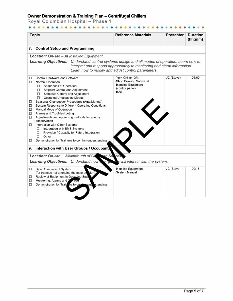
Topic Reference Materials Presenter Duration (hh:mm)
7. Control Setup and Programming
Location: On-site – At Installed Equipment Learning Objectives: Understand control systems design and all modes of operation. Learn how to
interpret and respond appropriately to monitoring and alarm information. Learn how to modify and adjust control parameters.
⬜ Control Hardware and Software ⬜ Normal Operation
⬜ Sequences of Operation ⬜ Setpoint Control and Adjustment ⬜ Schedule Control and Adjustment ⬜ Occupied/Unoccupied Modes
⬜ Seasonal Changeover Procedures (Auto/Manual) ⬜ System Response to Different Operating Conditions ⬜ Manual Mode of Operation ⬜ Alarms and Troubleshooting ⬜ Adjustments and optimizing methods for energy
conservation ⬜ Interaction with Other Systems
⬜ Integration with BMS Systems ⬜ Provision / Capacity for Future Integration ⬜ Other
⬜ Demonstration by Trainees to confirm understanding
- York Chiller IOM - Shop Drawing Submittal - Installed Equipment (control panel)
- BAS
JC (Steve) 03:00
9. Interaction with User Groups / Occupants
Location: On-site – Walkthrough of Occupied Spaces Learning Objectives: Understand how user groups will interact with the system.
⬜ Basic Overview of System (for trainees not attending the main session)
⬜ Review of Equipment in Occupied Spaces ⬜ Monitoring, Alarms and Controls ⬜ Demonstration by Trainees to confirm understanding
- Installed Equipment - System Manual
JC (Steve) 00:15
SAMPLE
Owner Demonstration & Training Plan – Centrifugal Chillers Royal Columbian Hospital – Phase 1
Page 6 of 7
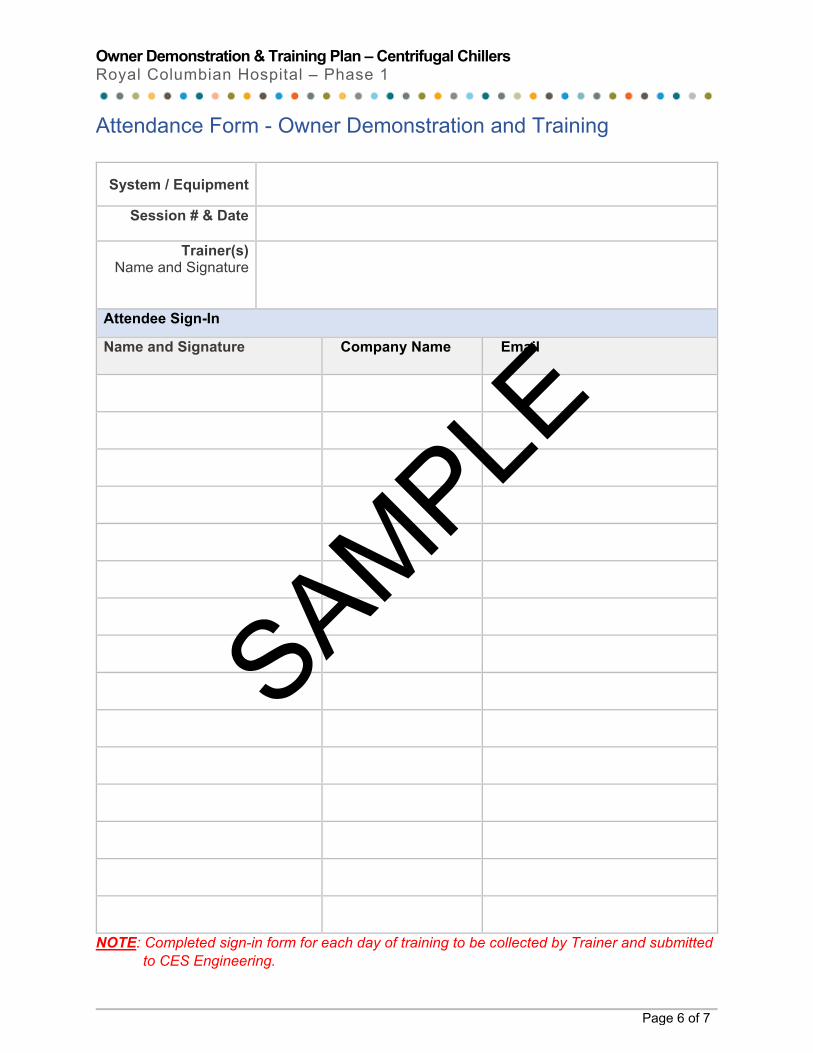
Attendance Form - Owner Demonstration and Training
System / Equipment
Session # & Date
Trainer(s) Name and Signature
Attendee Sign-In
Name and Signature Company Name Email
NOTE: Completed sign-in form for each day of training to be collected by Trainer and submitted to CES Engineering.
SAMPLE
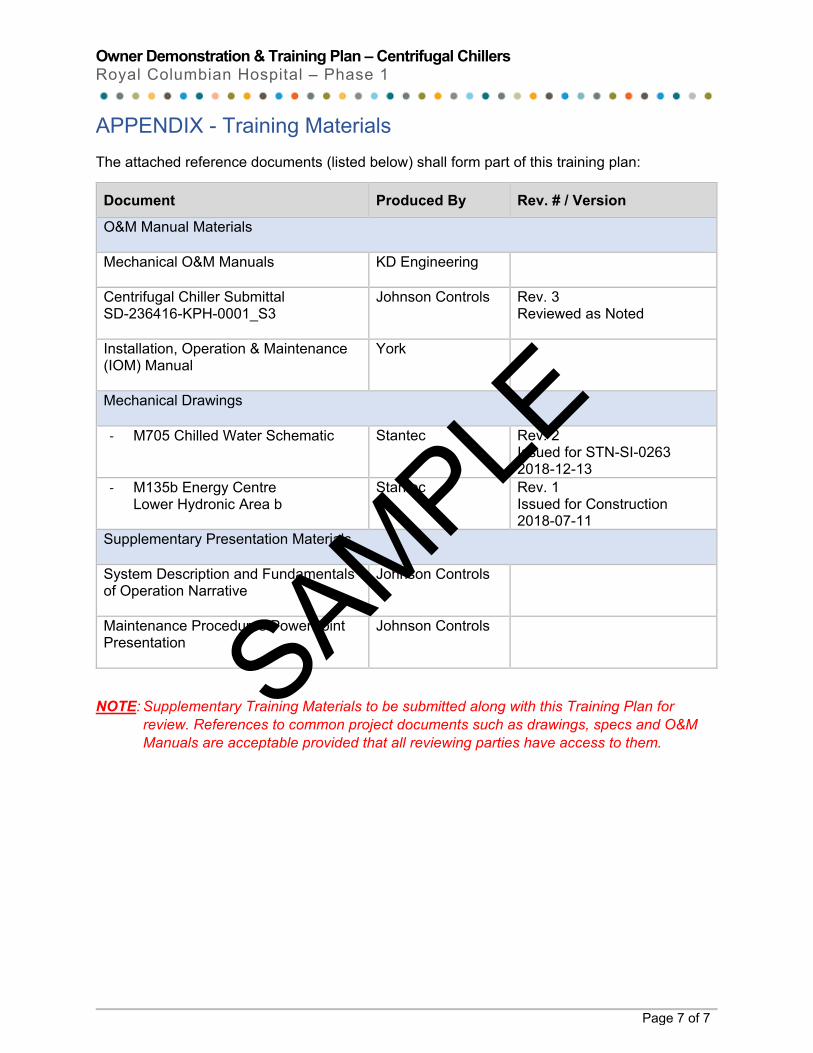
Owner Demonstration & Training Plan – Centrifugal Chillers Royal Columbian Hospital – Phase 1
Page 7 of 7
APPENDIX - Training Materials The attached reference documents (listed below) shall form part of this training plan:
Document Produced By Rev. # / Version
O&M Manual Materials Mechanical O&M Manuals
KD Engineering
Centrifugal Chiller Submittal SD-236416-KPH-0001_S3
Johnson Controls Rev. 3 Reviewed as Noted
Installation, Operation & Maintenance (IOM) Manual
York
Mechanical Drawings - M705 Chilled Water Schematic Stantec Rev. 2
Issued for STN-SI-0263 2018-12-13
- M135b Energy Centre Lower Hydronic Area b
Stantec Rev. 1 Issued for Construction 2018-07-11
Supplementary Presentation Materials System Description and Fundamentals of Operation Narrative
Johnson Controls
Maintenance Procedures PowerPoint Presentation
Johnson Controls
NOTE: Supplementary Training Materials to be submitted along with this Training Plan for review. References to common project documents such as drawings, specs and O&M Manuals are acceptable provided that all reviewing parties have access to them.
SAMPLE
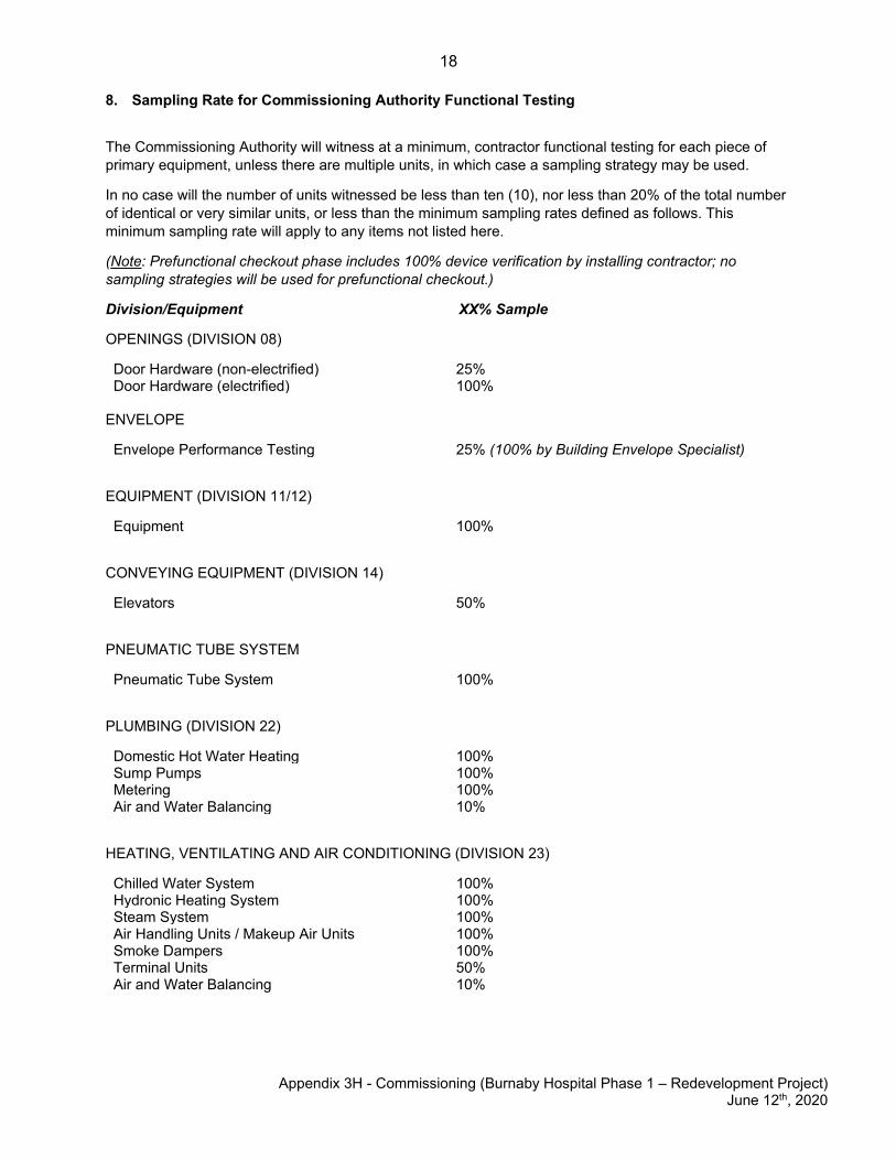
18
Appendix 3H - Commissioning (Burnaby Hospital Phase 1 – Redevelopment Project)
June 12th, 2020
8. Sampling Rate for Commissioning Authority Functional Testing
The Commissioning Authority will witness at a minimum, contractor functional testing for each piece of primary equipment, unless there are multiple units, in which case a sampling strategy may be used.
In no case will the number of units witnessed be less than ten (10), nor less than 20% of the total number of identical or very similar units, or less than the minimum sampling rates defined as follows. This minimum sampling rate will apply to any items not listed here.
(Note: Prefunctional checkout phase includes 100% device verification by installing contractor; no sampling strategies will be used for prefunctional checkout.)
Division/Equipment XX% Sample
OPENINGS (DIVISION 08)
Door Hardware (non-electrified) 25% Door Hardware (electrified) 100%
ENVELOPE
Envelope Performance Testing 25% (100% by Building Envelope Specialist)
EQUIPMENT (DIVISION 11/12)
Equipment 100%
CONVEYING EQUIPMENT (DIVISION 14)
Elevators 50%
PNEUMATIC TUBE SYSTEM
Pneumatic Tube System 100%
PLUMBING (DIVISION 22)
Domestic Hot Water Heating 100% Sump Pumps 100% Metering 100% Air and Water Balancing 10%
HEATING, VENTILATING AND AIR CONDITIONING (DIVISION 23)
Chilled Water System 100% Hydronic Heating System 100% Steam System 100% Air Handling Units / Makeup Air Units 100% Smoke Dampers 100% Terminal Units 50% Air and Water Balancing 10%
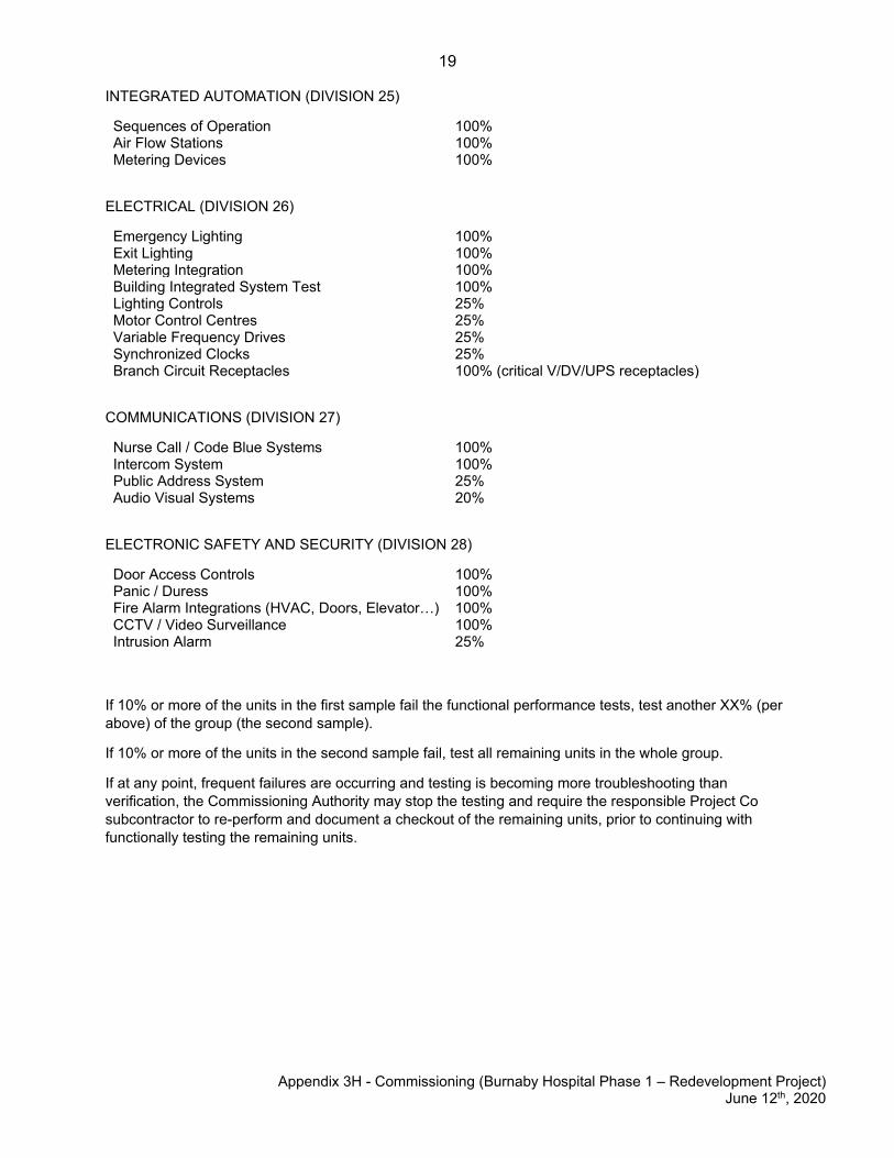
19
Appendix 3H - Commissioning (Burnaby Hospital Phase 1 – Redevelopment Project)
June 12th, 2020
INTEGRATED AUTOMATION (DIVISION 25)
Sequences of Operation 100% Air Flow Stations 100% Metering Devices 100%
ELECTRICAL (DIVISION 26)
Emergency Lighting 100% Exit Lighting 100% Metering Integration 100% Building Integrated System Test 100% Lighting Controls 25% Motor Control Centres 25% Variable Frequency Drives 25% Synchronized Clocks 25% Branch Circuit Receptacles 100% (critical V/DV/UPS receptacles)
COMMUNICATIONS (DIVISION 27)
Nurse Call / Code Blue Systems 100% Intercom System 100% Public Address System 25% Audio Visual Systems 20%
ELECTRONIC SAFETY AND SECURITY (DIVISION 28)
Door Access Controls 100% Panic / Duress 100% Fire Alarm Integrations (HVAC, Doors, Elevator…) 100% CCTV / Video Surveillance 100% Intrusion Alarm 25%
If 10% or more of the units in the first sample fail the functional performance tests, test another XX% (per above) of the group (the second sample).
If 10% or more of the units in the second sample fail, test all remaining units in the whole group.
If at any point, frequent failures are occurring and testing is becoming more troubleshooting than verification, the Commissioning Authority may stop the testing and require the responsible Project Co subcontractor to re-perform and document a checkout of the remaining units, prior to continuing with functionally testing the remaining units.
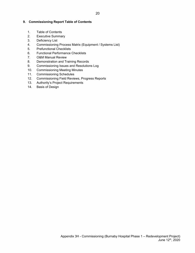
20
Appendix 3H - Commissioning (Burnaby Hospital Phase 1 – Redevelopment Project) June 12th, 2020
9. Commissioning Report Table of Contents
1. Table of Contents2. Executive Summary3. Deficiency List4. Commissioning Process Matrix (Equipment / Systems List)5. Prefunctional Checklists6. Functional Performance Checklists7. O&M Manual Review8. Demonstration and Training Records9. Commissioning Issues and Resolutions Log10. Commissioning Meeting Minutes11. Commissioning Schedules12. Commissioning Field Reviews, Progress Reports13. Authority’s Project Requirements14. Basis of Design
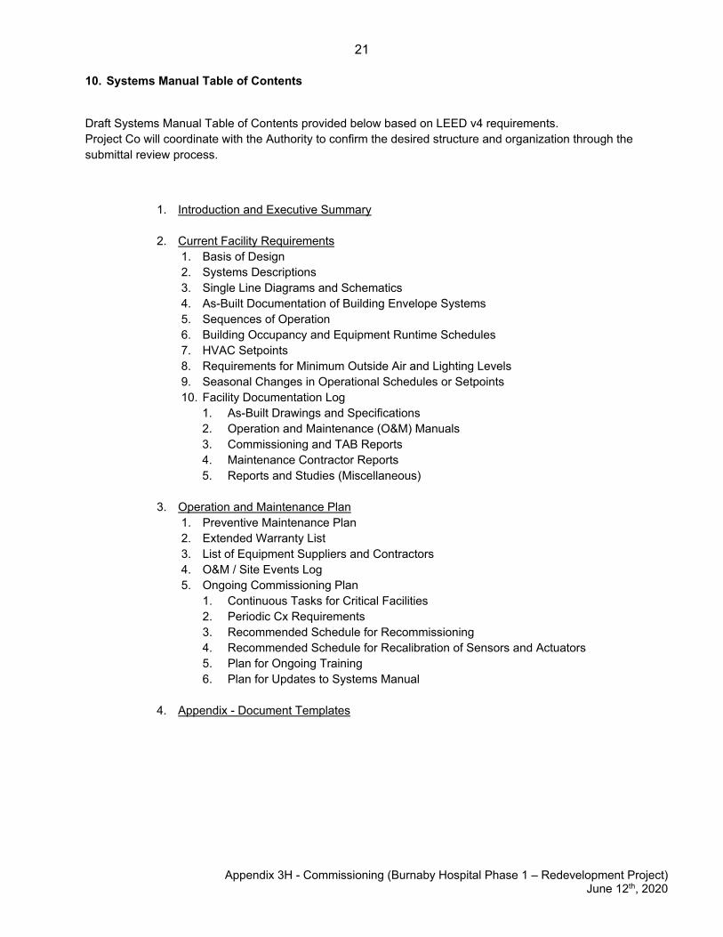
21
Appendix 3H - Commissioning (Burnaby Hospital Phase 1 – Redevelopment Project)
June 12th, 2020
10. Systems Manual Table of Contents
Draft Systems Manual Table of Contents provided below based on LEED v4 requirements. Project Co will coordinate with the Authority to confirm the desired structure and organization through the submittal review process.
1. Introduction and Executive Summary
2. Current Facility Requirements 1. Basis of Design 2. Systems Descriptions 3. Single Line Diagrams and Schematics 4. As-Built Documentation of Building Envelope Systems 5. Sequences of Operation 6. Building Occupancy and Equipment Runtime Schedules 7. HVAC Setpoints 8. Requirements for Minimum Outside Air and Lighting Levels 9. Seasonal Changes in Operational Schedules or Setpoints 10. Facility Documentation Log
1. As-Built Drawings and Specifications 2. Operation and Maintenance (O&M) Manuals 3. Commissioning and TAB Reports 4. Maintenance Contractor Reports 5. Reports and Studies (Miscellaneous)
3. Operation and Maintenance Plan
1. Preventive Maintenance Plan 2. Extended Warranty List 3. List of Equipment Suppliers and Contractors 4. O&M / Site Events Log 5. Ongoing Commissioning Plan
1. Continuous Tasks for Critical Facilities 2. Periodic Cx Requirements 3. Recommended Schedule for Recommissioning 4. Recommended Schedule for Recalibration of Sensors and Actuators 5. Plan for Ongoing Training 6. Plan for Updates to Systems Manual
4. Appendix - Document Templates
Related Documents