ABC Ltd. Water Management System Lagos Port, Nigeria Technical Proposal‐ Water Management System Rev‐0 Page 24 of 27 Water supply pumps

Welcome message from author
This document is posted to help you gain knowledge. Please leave a comment to let me know what you think about it! Share it to your friends and learn new things together.
Transcript
ABC Ltd. Water Management System
Lagos Port, Nigeria
Technical Proposal‐ Water Management System Rev‐0 Page 24 of 27
Water supply pumps

GRUNDFOS HS HORIZONTAL SPLIT CASE tHE GRUNDFOS GIANt MAxIMUM FlOw FOR MUltIplE ApplIcAtION AREAS
GRUNDFOSHORIZONTAL SPLIT CASE
The Grundfos Horizontal Split Case is the giant in the Grundfos product range. It combines double suction ports with high flow and in-line pipe connection. The Horizontal Split Case virtually eliminates radial loads by hydraulically balancing the liquid within its casing and it offers benefits like improved efficiency, minimised vibration, extended seal and bearing life and low noise levels.
Grundfos application areas:• Industrialplants•Publicwatersupply•Districtcooling/heatingplants•Air-con/heatingsystems•Fireprotection•Coolingsystems• Irrigation
GRUNDFOS Management A/SPoul Due Jensens Vej 7 DK-8850 BjerringbroTel: +45 87 50 14 00
www.grundfos.com
9690
5270
110
8
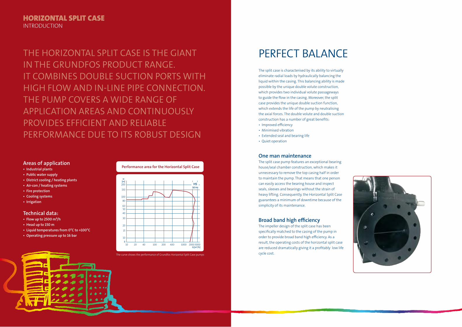
The hORizONTal SpliT caSe iS The GiaNT iN The GRUNDFOS pRODUcT RaNGe. iT cOmbiNeS DOUble SUcTiON pORTS wiTh hiGh FlOw aND iN-liNe pipe cONNecTiON. The pUmp cOveRS a wiDe RaNGe OF applicaTiON aReaS aND cONTiNUOUSly pROviDeS eFFicieNT aND Reliable peRFORmaNce DUe TO iTS RObUST DeSiGN
HORIZONTAL SPLIT CASEINtRODUctION
The split case is characterised by its ability to virtually eliminate radial loads by hydraulically balancing the liquid within the casing. This balancing ability is made possible by the unique double volute construction, which provides two individual volute passageways to guide the flow in the casing. Moreover, the split case provides the unique double suction function, which extends the life of the pump by neutralising the axial forces. The double volute and double suction construction has a number of great benefits:• Improvedefficiency• Minimisedvibration• Extendedsealandbearinglife• Quietoperation
One man maintenanceThe split case pump features an exceptional bearing house/sealchamberconstruction,whichmakesitunnecessary to remove the top casing half in order to maintain the pump. That means that one person can easily access the bearing house and inspect seals, sleeves and bearings without the strain of heavy lifting. Consequently, the Horizontal Split Case guarantees a minimum of downtime because of the simplicity of its maintenance.
Broad band high efficiencyThe impeller design of the split case has been specifically matched to the casing of the pump in ordertoprovidebroadbandhighefficiency.Asaresult, the operating costs of the horizontal split case are reduced dramatically giving it a profitably low life cycle cost.
Performance area for the Horizontal Split Case
10 20 40 100 200 400 1000 20003000Q [m³/h]
810
15
20
30
405060
80100
150
200[m]H
HS50 Hz
Areas of application• Industrialplants• Publicwatersupply• Districtcooling/heatingplants• Air-con/heatingsystems• Fireprotection• Coolingsystems• Irrigation
Technical data:• Flowupto2500m³/h• Headupto150m• Liquidtemperaturesfrom0°Cto+100°C• Operatingpressureupto16bar
peRFecT balaNce
The curve shows the performance of Grundfos Horizontal Split Case pumps

HORIZONTAL SPLIT CASEtHE DEtAIlS
FlexiblegridcouplingThe flexible grid coupling is called the Rolls-Royce of couplings because it is able to compensate for misalignments to a certain degree. The flexible grid coupling comes as a standard feature in the Horizontal Split Case.
RenewableneckringsAllHorizontalSplitCasepumpsareequippedwithrenewable neck rings as a standard feature, which means that there is only wear on the bronze neck ring in the area between impeller and pump casing. This way the renewable neck rings help protect the costly casing.
DoublesuctionThe unique double suction function extends the life of the pump and motor by neutralising the axial forces.
DoublevoluteThe double volute function eliminates radial loads by hydraulically balancing the liquid within the casing. Three major advantages are improved efficiency, minimised vibration and extended seal and bearing life.
Easy replacementThe bearings and shaft seals can be replaced without dismantling the upper casing, which makes maintenance simple and reduces downtime.
Clockwiseandcounter-clockwiseoperationThe motor can be connected to split case pumps at both shaft ends, which provides you with the flexibility to place the motor where it is most convenient in the installation.

Life Cycle Cost (LCC) analysis is an objective standard that allows you to benchmark different pump solutions and suppliers, based on initial investment and the costs of installation, maintenance and energy.
By considering LCC when choosing your pumps, you can help reduce CO2 dramatically and thereby make an important contribution to the well-being of our planet.
Save mONey while SaviNG The plaNeT
HowtocalculateLifeCycleCost(LCC)
LCC = Cic + Cin + Ce + Co + Cm + Cs + Cenv + CdCic = initialcosts,purchasepriceCin = installation and commissioningCe = energy costsCo = operation cost (labour cost)Cm = maintenance and repair costsCs = downtime costs (loss of production)Cenv = environmental costsCd =decommissioning/disposalcosts
HORIZONTAL SPLIT CASESUStAINABIlItY
Energycostsaccountforupto90%oftheoverallcostof a pump during its lifetime. In other words, thinking about energy efficiency can save you a lot of money.
ThiNkiNG bUilDiNGSAtGrundfosCBS,wearealwaysthinkingbuildings,andour products contribute to making buildings that can almost think for themselves. We do not just consider our products as stand-alone devices – we consider them an integral part of a living building whose purpose is to function in the best way possible for its inhabitants.
Grundfos CBS offers products across the full range of applications, including heating, air conditioning, waste water, booster systems, fire protection systems and district energy.
Our expertise is founded in decades of global experience and we are proud to share our knowledge with our clients. We are also determined to take the lead on new technologies and innovation opportunities.
To learn more about Grundfos CBS and to find out how we can be of assistance, contact Grundfos or visit us at www.grundfos.com/commercialbuilding.
Make the most of Grundfos CBS – visit the Thinking Buildings Universe at www.grundfos.com/commercialbuilding. Our website contains a range of services that function as your online Grundfos CBS expert:
• QuickPumpSelectionwithanextensive productdatabaseanddimensioningtoolthathelpsyouchoosetherightpumpforyourneeds
• E-learningprogrammethatletsyouimproveyourspecialistknowledge
• AccesstoThinkingBuildingsE-News,whichkeepsyouuptodateonthelatesttechnology,productinformationandbackgroundmaterial
• Lexiconwhereyoucanlookupdefinitions ofrelevantprofessionalterms
Welcome to the Grundfos CBS Thinking Buildings Universe!
explORe OUR ONliNe UNiveRSe
AnLCCprocesswillshowthemostcosteffectivesolution within the limits of available data.
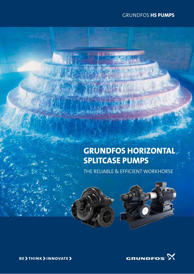
GRUNDFOS HORIZONTAL SPLITCASE PUMPSThe Reliable & efficienT WoRkhoRse
GRUnDfos HS PUMPS
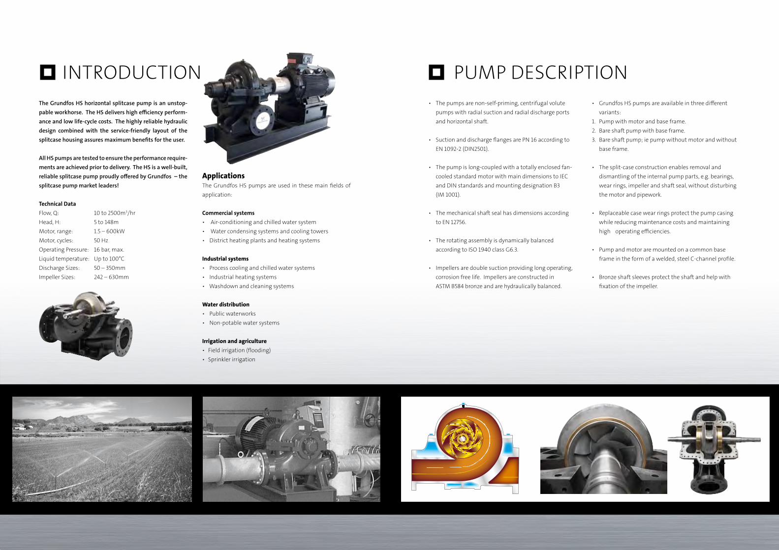
IntroductIon The Grundfos HS horizontal splitcase pump is an unstop-pable workhorse. The HS delivers high efficiency perform-ance and low life-cycle costs. The highly reliable hydraulic design combined with the service-friendly layout of the splitcase housing assures maximum benefits for the user. All HS pumps are tested to ensure the performance require-ments are achieved prior to delivery. The HS is a well-built, reliable splitcase pump proudly offered by Grundfos – the splitcase pump market leaders!
Technical DataFlow, Q: 10 to 2500m3/hrHead, H: 5 to 148mMotor, range: 1.5 – 600kWMotor, cycles: 50 Hzoperating Pressure: 16 bar, max.Liquid temperature: up to 100°cdischarge Sizes: 50 – 350mmImpeller Sizes: 242 – 630mm
Applicationsthe Grundfos HS pumps are used in these main fields of application:
Commercial systems• Air-conditioningandchilledwatersystem• Watercondensingsystemsandcoolingtowers• Districtheatingplantsandheatingsystems
Industrial systems• Processcoolingandchilledwatersystems• Industrialheatingsystems• Washdownandcleaningsystems
Water distribution• Publicwaterworks• Non-potablewatersystems
Irrigation and agriculture• Fieldirrigation(flooding)• Sprinklerirrigation
PuMP dEScrIPtIon• Thepumpsarenon-self-priming,centrifugalvolute pumps with radial suction and radial discharge ports and horizontal shaft.
• SuctionanddischargeflangesarePN16accordingto EN1092-2(DIN2501).
• Thepumpislong-coupledwithatotallyenclosedfan- cooled standard motor with main dimensions to IEc and dIn standards and mounting designation B3 (IM1001).
• Themechanicalshaftsealhasdimensionsaccording to En 12756.
• Therotatingassemblyisdynamicallybalanced according to ISo 1940 class G6.3.
• Impellersaredoublesuctionprovidinglongoperating, corrosion free life. Impellers are constructed in ASTMB584bronzeandarehydraulicallybalanced.
• GrundfosHSpumpsareavailableinthreedifferent variants:1. Pump with motor and base frame.2. Bare shaft pump with base frame.3. Bare shaft pump; ie pump without motor and without base frame.
• Thesplit-caseconstructionenablesremovaland dismantling of the internal pump parts, e.g. bearings, wear rings, impeller and shaft seal, without disturbing the motor and pipework.
• Replaceablecasewearringsprotectthepumpcasing while reducing maintenance costs and maintaining high operating efficiencies.
• Pumpandmotoraremountedonacommonbase frameintheformofawelded,steelC-channelprofile.
• Bronzeshaftsleevesprotecttheshaftandhelpwith fixation of the impeller.
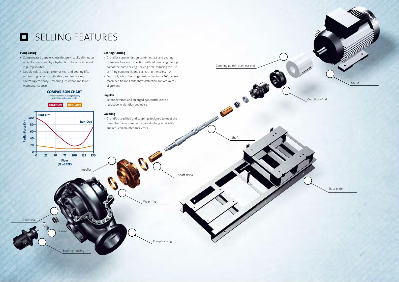
SELLINGFEATURES Pump casing• Compensateddoublevolutedesignvirtuallyeliminates radial forces caused by a hydraulic imbalance inherent inpumpvolutes• Doublevolutedesignextendssealandbearinglife, minimizingnoiseandvibration,andimproving operating efficiency – meaning less wear and lower maintenance costs
Bearing Housing• Grundfos superior design combines seal and bearing chamberstoallowinspectionwithoutremovingthetop halfofthepumpcasing–savingtime,reducingtheuse of lifting equipment, and decreasing the safety risk• Compact,robusthousingconstructionhasa360-degree machinedfitandlimitsshaftdeflectionandoptimizes alignment
Impeller• Extendedvanesandenlargedeyecontributetoa reductioninvibrationandnoise
Coupling• Grundfosspecifiedgridcouplingdesignedtomeetthe pumptorquerequirementsprovideslongservicelife and reduced maintenance costs
Motor
Base plate
Impeller
Pump housing
Couplingguard-stainlesssteel
Coupling-Grid
Shaft
Wear ring
Bearing housing
Shaftsleeve
Shaft seal
Bearing

20 25 30 40 50 60 80 100 150 200 250 300 400 500Q [m�/h]
10
14
20
30
40
50
60
80
100
120
140
[m]H
HS
2-pole, 50 HzVers ion 5
125- 100-305
125- 100-280100-80-24265-50-242
20 30 40 50 60 80 100 150 200 300 400 500 600 800 1000 1500 2000 3000Q [m�/h]
4
56
8
10
15
20
2530
40
5060
80
100
150
200
[m]H
HS
4-pole, 50 HzVers ion 5
400-350-397
350-250-630
350-250-498
300-250-381
300-250-305
300-200-489
250-200-381
250-200-305
200-150-508200-150-483
200-150-381
200-150-305C
200-150-305A
1 50-1 25-381
150-125-305
125-100-381
125-100-305
125-100-280
100-80-356
100-80-242
65-50-331
65-50-242
60 80 100 150 200 300 400 500 600 800 1000 1500 2000 2500Q [m�/h]
4
5
6
7
8
10
15
20
30
40
50
60
70[m]H
HS
6-pole, 50 HzVers ion 5
400-350-397
350-300-508
350-250-630
350-250-498
300-250-381
300-250-305
300-200-489
250-200-381
200-150-508
200-150-483
HSRANGEovERvIEW 2/4/6 PoLE MotorS DoCUMENTATIoN Data Booklet• Technicalproductdescriptions• Productapplications• Performancecurves• Accessories• AvailableinWebCAPS
I&O• Installationandoperation• Warningsandsafetyrequirements• Targetedforinstallers,servicers,andend-users• Shippedwiththepump
Service Instructions• Descriptionofserviceprocedures• Intendedforservicetechnicians• AvailableinWebCAPS
WebCAPS/WinCAPS• Pumpselectionprogram• PDFliteraturefilesavailable• Servicevideos• Replacementpumpinformation• PumpCADdrawings
10 Ways to Kill Your HS Pump
1. Overwork itWorkthepumpcontinuouslyathighercapacities,flows,heads,or speeds than originally specified.
2. Starve itNevergreaseoroilthepump.
3. Choke it• Lowerthewaterlevelinthesump.• Letthesuctionstrainerclogandnevercleanit.• Letthetemperatureoffluidrisewithoutraising the suction pressure.
4. Fry itoperateatshutofffora longtimewiththebypass lineclosedtightwillconvertyourpowertoheat.
5. Poison itChangethepumpedfluidwithoutcheckingwiththemanufac-turer(forexampleaddingchemicals).
6. Stab itRemovethesuctionstrainerswhichwillintroducegrit,sand,andscaleintothefluid.
7. Break its limbsImposeheavypipingloadsonthesuctionanddischarge nozzle, either through initial misalignment or through thermal expansion.
8. Shake itDon’talignatinstallationorinstallonaflimsyfoundation.
9. Drown itFor a packed pump with a drain for the gland leakage: • Plugthedrainwithacigarettebutt,gumorpaper.• Removethewatershield.• Lineupthesplitsonthepackingrings.
10. Neglect check-ups• Ignorethemanufacturer’srecommendationsfor “check-ups”• Don’tcheckpacking,gaskets,o-rings,or other small parts. • Don’teverrepaintit,orlubricatethecoupling, if required. • Don’tcheckvibration.
IMPoRTANTSERvICE&INSTALLATIoNINFoRMATIoN

Being responsible is our foundationThinking ahead makes it possible
Innovation is the essence
FOr PrODuCT requeSTS, PleASe CONTACT:[email protected]
GruNDFOS A/SPoul Due Jensens Vej 7DK-8850 BjerringbroTel: +45 87 50 14 00
www.grundfos.com/industryThe name Grundfos, the Grundfos logo, and the payoff Be–Think–Innovate are registrated trademarks owned by Grundfos Management A/S or Grundfos A/S, Denmark. All rights reserved worldwide.
PN 9
7718
637

ABC Ltd. Water Management System
Lagos Port, Nigeria
Technical Proposal‐ Water Management System Rev‐0 Page 24 of 27
Dosing pumps
DIGITAL DOSING
GRUNDFOS DME/DMS

No more complicated calculations
In the past, traditional dosing equipment forced you to resort
to complicated calculations to find the right setting. The exact
dosage required to ensure that your dosing system was econo-
mical and safe had to be found by trial and error. And you
would have to do it all over again whenever you needed to
make adjustments. That all changed when Grundfos brought
you Digital Dosing. Now, you simply specify the dosage you
want and let the pump do the rest – with perfect confidence
that you will get what you want.
Digital Dosing represents innovation in its purest form. This
patented Grundfos solution uses new principles and methods
to set an entirely new standard for dosing technology. It makes
your job a lot easier and your results a lot better.
Focus on user-friendliness
Digital Dosing is about complete precision combined with
complete user-friendliness. It is made possible through the
use of an innovative drive principle in a diaphragm dosing
pump. More technical information can be found elsewhere in
this brochure, but all you really need to concern yourself with
is the easy-to-use control panel. Just push the buttons a few
times to specify the dose you want, and the pump will take care
Digital Dosing represents innovation in its purest form!
of the rest. Quite simply, Digital Dosing means that what you
set is what you get.
Proven technology
Ever since Digital Dosing was introduced, enthusiastic custo-
mer responses have shown that there was a real demand for
better dosing technology. Aside from the obvious advantages
of precise, trouble-free dosing, many customers point to the
remarkable reliability of Grundfos Digital Dosing as a key
benefit. This is technology you can trust.
We have always been confident that Digital Dosing was the
way to go, and satisfied users worldwide now support this
conviction. In effect, Grundfos has set the agenda for the
future of dosing. And you can trust us to remain ahead of
the game.
To give even more enterprises the chance to benefit from
Digital Dosing, we have expanded the product family to cover
the full range from 2,5 ml/hour to 150 l/hour – all handled
by just a few highly versatile and efficient models. So if you
haven’t gone digital yet, we urge you to try it out. You will
never want to go back.
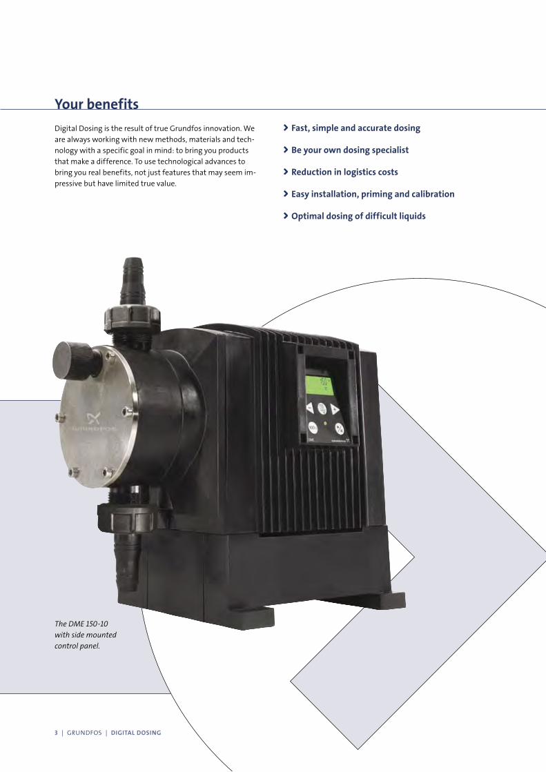
The DME 150-10
with side mounted
control panel.
Your benefits
Digital Dosing is the result of true Grundfos innovation. We
are always working with new methods, materials and tech-
nology with a specific goal in mind: to bring you products
that make a difference. To use technological advances to
bring you real benefits, not just features that may seem im-
pressive but have limited true value.
Fast, simple and accurate dosing
Be your own dosing specialist
Reduction in logistics costs
Easy installation, priming and calibration
Optimal dosing of difficult liquids
3 | GRUNDFOS | DIGITAL DOSING

Accurate dosing -
cutt
ing
line
only

The large Digital Dosing range
comprises two pump models
housed in the same size cabinet.
Both are equipped with brushless
DC motors.
The smaller Digital Dosing range comprises five pump models housed in two cabinet sizes.
These use a stepper motor to ensure precise dosing.
Grundfos Digital
5 | GRUNDFOS | DIGITAL DOSING
cutt
ing
line
only
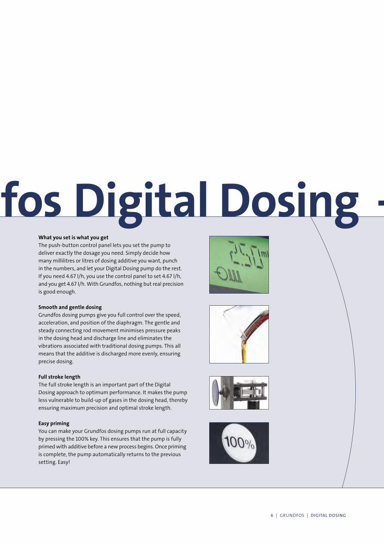
What you set is what you get
The push-button control panel lets you set the pump to
deliver exactly the dosage you need. Simply decide how
many millilitres or litres of dosing additive you want, punch
in the numbers, and let your Digital Dosing pump do the rest.
If you need 4.67 l/h, you use the control panel to set 4.67 l/h,
and you get 4.67 l/h. With Grundfos, nothing but real precision
is good enough.
Smooth and gentle dosing
Grundfos dosing pumps give you full control over the speed,
acceleration, and position of the diaphragm. The gentle and
steady connecting rod movement minimises pressure peaks
in the dosing head and discharge line and eliminates the
vibrations associated with traditional dosing pumps. This all
means that the additive is discharged more evenly, ensuring
precise dosing.
Full stroke length
The full stroke length is an important part of the Digital
Dosing approach to optimum performance. It makes the pump
less vulnerable to build-up of gases in the dosing head, thereby
ensuring maximum precision and optimal stroke length.
Easy priming
You can make your Grundfos dosing pumps run at full capacity
by pressing the 100% key. This ensures that the pump is fully
primed with additive before a new process begins. Once priming
is complete, the pump automatically returns to the previous
setting. Easy!
- Grundfos Digital Dosing
6 | GRUNDFOS | DIGITAL DOSING
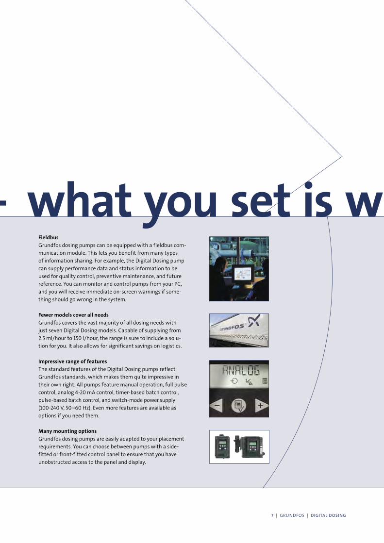
Fieldbus
Grundfos dosing pumps can be equipped with a fieldbus com-
munication module. This lets you benefit from many types
of information sharing. For example, the Digital Dosing pump
can supply performance data and status information to be
used for quality control, preventive maintenance, and future
reference. You can monitor and control pumps from your PC,
and you will receive immediate on-screen warnings if some-
thing should go wrong in the system.
Fewer models cover all needs
Grundfos covers the vast majority of all dosing needs with
just seven Digital Dosing models. Capable of supplying from
2.5 ml/hour to 150 l/hour, the range is sure to include a solu-
tion for you. It also allows for significant savings on logistics.
Impressive range of features
The standard features of the Digital Dosing pumps reflect
Grundfos standards, which makes them quite impressive in
their own right. All pumps feature manual operation, full pulse
control, analog 4-20 mA control, timer-based batch control,
pulse-based batch control, and switch-mode power supply
(100-240 V, 50–60 Hz). Even more features are available as
options if you need them.
Many mounting options
Grundfos dosing pumps are easily adapted to your placement
requirements. You can choose between pumps with a side-
fitted or front-fitted control panel to ensure that you have
unobstructed access to the panel and display.
- what you set is what you get
7 | GRUNDFOS | DIGITAL DOSING
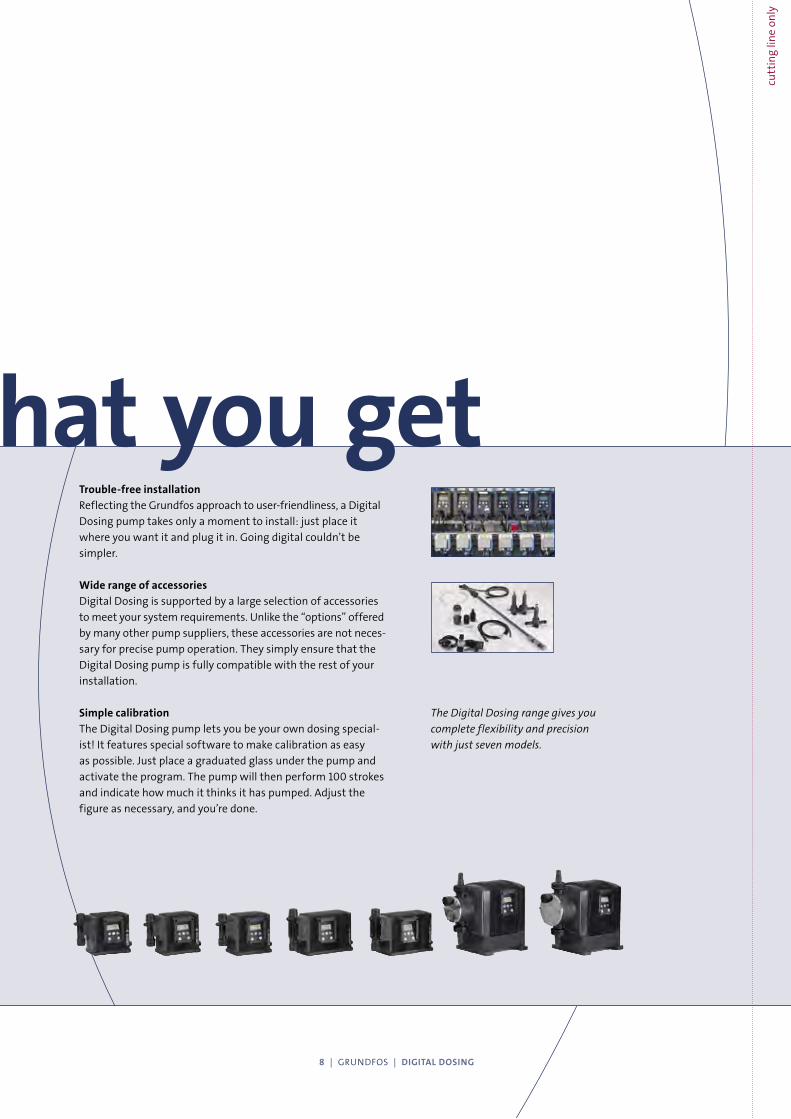
Trouble-free installation
Reflecting the Grundfos approach to user-friendliness, a Digital
Dosing pump takes only a moment to install: just place it
where you want it and plug it in. Going digital couldn’t be
simpler.
Wide range of accessories
Digital Dosing is supported by a large selection of accessories
to meet your system requirements. Unlike the “options” offered
by many other pump suppliers, these accessories are not neces-
sary for precise pump operation. They simply ensure that the
Digital Dosing pump is fully compatible with the rest of your
installation.
Simple calibration
The Digital Dosing pump lets you be your own dosing special-
ist! It features special software to make calibration as easy
as possible. Just place a graduated glass under the pump and
activate the program. The pump will then perform 100 strokes
and indicate how much it thinks it has pumped. Adjust the
figure as necessary, and you’re done.
The Digital Dosing range gives you
complete flexibility and precision
with just seven models.
what you set is what you get
8 | GRUNDFOS | DIGITAL DOSING
cutt
ing
line
only
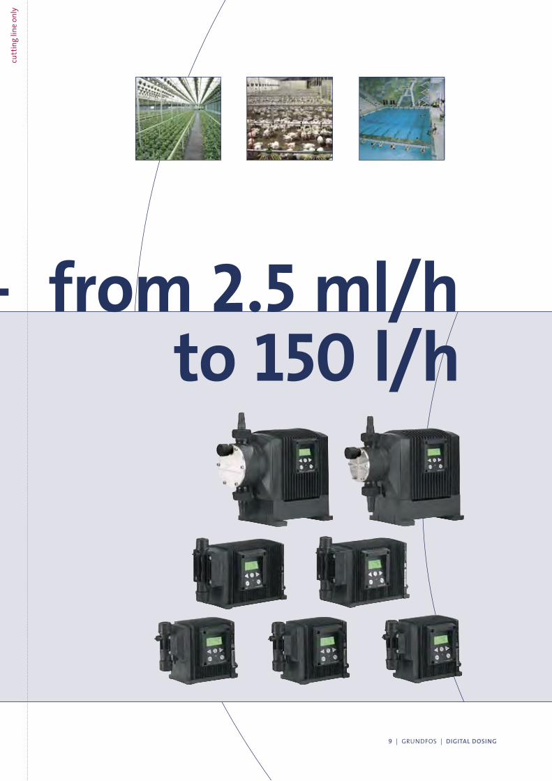
Accurate dosing from 2.5 ml/h- to 150 l/h
9 | GRUNDFOS | DIGITAL DOSING
cutt
ing
line
only
*
*
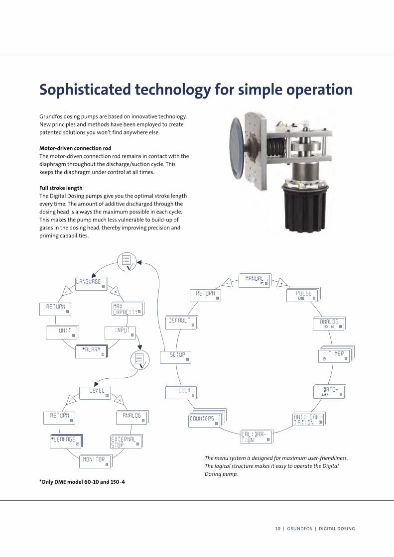
Sophisticated technology for simple operation
Grundfos dosing pumps are based on innovative technology.
New principles and methods have been employed to create
patented solutions you won’t find anywhere else.
Motor-driven connection rod
The motor-driven connection rod remains in contact with the
diaphragm throughout the discharge/suction cycle. This
keeps the diaphragm under control at all times.
Full stroke length
The Digital Dosing pumps give you the optimal stroke length
every time. The amount of additive discharged through the
dosing head is always the maximum possible in each cycle.
This makes the pump much less vulnerable to build-up of
gases in the dosing head, thereby improving precision and
priming capabilities.
The menu system is designed for maximum user-friendliness.
The logical structure makes it easy to operate the Digital
Dosing pump.
*Only DME model 60-10 and 150-4
10 | GRUNDFOS | DIGITAL DOSING
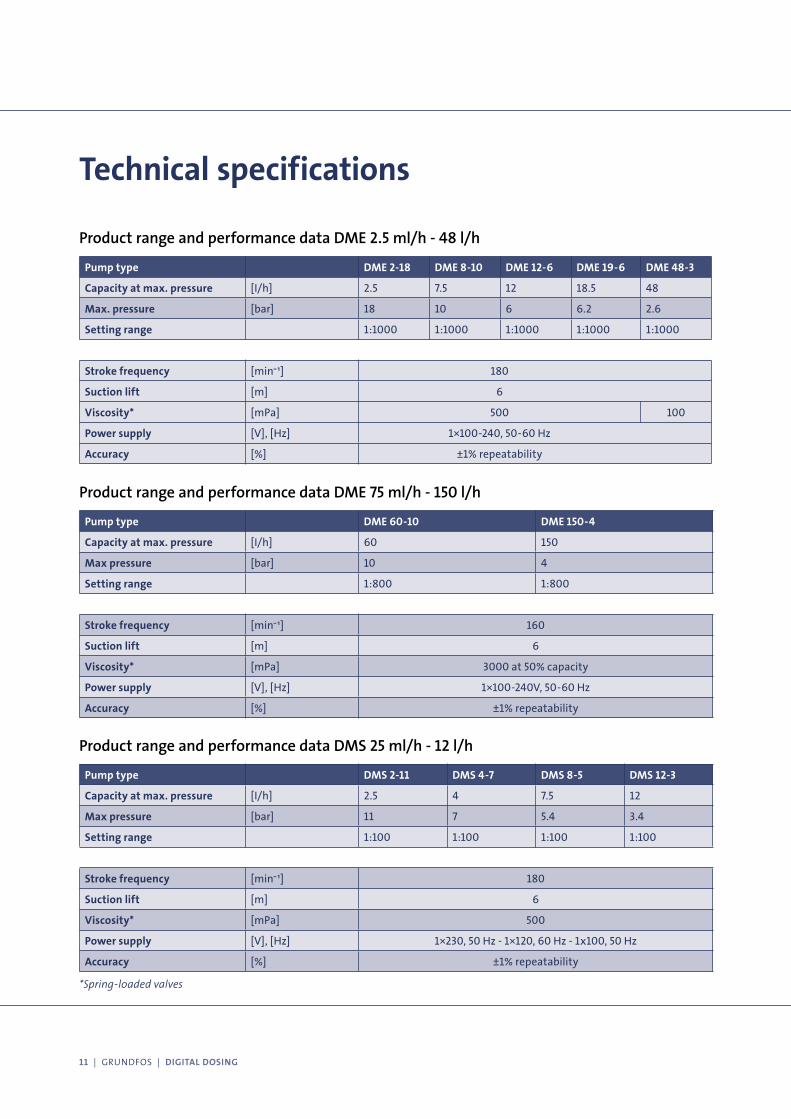
Technical specifications
Pump type DME 2-18 DME 8-10 DME 12-6 DME 19-6 DME 48-3
Capacity at max. pressure [I/h] 2.5 7.5 12 18.5 48
Max. pressure [bar] 18 10 6 6.2 2.6
Setting range 1:1000 1:1000 1:1000 1:1000 1:1000
Stroke frequency [min¯¹] 180
Suction lift [m] 6
Viscosity* [mPa] 500 100
Power supply [V], [Hz] 1×100-240, 50-60 Hz
Accuracy [%] ±1% repeatability
Product range and performance data DME 2.5 ml/h - 48 l/h
Pump type DME 60-10 DME 150-4
Capacity at max. pressure [I/h] 60 150
Max pressure [bar] 10 4
Setting range 1:800 1:800
Stroke frequency [min¯¹] 160
Suction lift [m] 6
Viscosity* [mPa] 3000 at 50% capacity
Power supply [V], [Hz] 1×100-240V, 50-60 Hz
Accuracy [%] ±1% repeatability
Product range and performance data DME 75 ml/h - 150 l/h
Pump type DMS 2-11 DMS 4-7 DMS 8-5 DMS 12-3
Capacity at max. pressure [I/h] 2.5 4 7.5 12
Max pressure [bar] 11 7 5.4 3.4
Setting range 1:100 1:100 1:100 1:100
Stroke frequency [min¯¹] 180
Suction lift [m] 6
Viscosity* [mPa] 500
Power supply [V], [Hz] 1×230, 50 Hz - 1×120, 60 Hz - 1x100, 50 Hz
Accuracy [%] ±1% repeatability
Product range and performance data DMS 25 ml/h - 12 l/h
*Spring-loaded valves
11 | GRUNDFOS | DIGITAL DOSING

The Grundfos Digital Dosing range
0
0 2 4 6 8 10 20 40 60 80 100 200Q [l/h]
2
4
6
8
10
12
14
16
18P [bar]
DME 2 -18
DME 60 - 10DME 8 - 10
DME 19 - 6DME 12 - 6
DME 150 - 4
DME 48 - 3
DME 2.5 ml/h to 12 l/h
Cabinet size 1, consisting of 3 stepper motor driven models. Max. pressure rate: 18, 10 and 6 bar
DME 19.5 ml/h to 48 l/h
Cabinet size 2, consisting of 2 stepper motor driven models. Max. pressure rate: 6.2 and 2.6 bar
DME 75 ml/h to 150 l/h
Cabinet size 3, consisting of 2 brushless DC motor driven models. Max. pressure rate: 10 and 4 bar
DMS 25 ml/h to 12 l/h
An excellent alternative to the Digital Dosing DME range consisting of 4 synchronous motor
driven models. Max. pressure rate: 11, 7, 5.4 and 3.4 bar
Grundfos covers the vast majority of all
dosing needs with just seven Digital Dosing
models. Capable of supplying from
2.5 ml/hour to 150 l/hour.
12 | GRUNDFOS | DIGITAL DOSING
cutt
ing
line
only
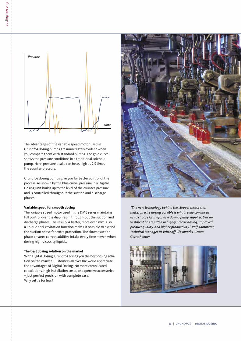
Pressure
Time
The advantages of the variable speed motor used in
Grundfos dosing pumps are immediately evident when
you compare them with standard pumps. The gold curve
shows the pressure conditions in a traditional solenoid
pump. Here, pressure peaks can be as high as 2.5 times
the counter-pressure.
Grundfos dosing pumps give you far better control of the
process. As shown by the blue curve, pressure in a Digital
Dosing unit builds up to the level of the counter-pressure
and is controlled throughout the suction and discharge
phases.
Variable speed for smooth dosing
The variable speed motor used in the DME series maintains
full control over the diaphragm through-out the suction and
discharge phases. The result? A better, more even mix. Also,
a unique anti-cavitation function makes it possible to extend
the suction phase for extra protection. The slower suction
phase ensures correct additive intake every time – even when
dosing high-viscosity liquids.
The best dosing solution on the market
With Digital Dosing, Grundfos brings you the best dosing solu-
tion on the market. Customers all over the world appreciate
the advantages of Digital Dosing: No more complicated
calculations, high installation costs, or expensive accessories
– just perfect precision with complete ease.
Why settle for less?
“The new technology behind the stepper motor that
makes precise dosing possible is what really convinced
us to choose Grundfos as a dosing pump supplier. Our in-
vestment has resulted in highly precise dosing, improved
product quality, and higher productivity.” Ralf Kammerer,
Technical Manager at Wisthoff Glassworks, Group
Gerresheimer
13 | GRUNDFOS | DIGITAL DOSING
cutt
ing
line
only

www.grundfos.com
VEN
TUR
E I/
S
Being responsible is our foundationThinking ahead makes it possible
Innovation is the essence
Innovation in its purest form
Grundfos created digital dosing – both as a concept and
by developing the world’s first ever digital dosing pump
range. Our digital dosing pumps represent innovation in
its purest form, and this patented new method sets an
entirely new standard for dosing technology. It enables
our customers to achieve extreme accuracy literally at
the touch of a button.
Ongoing research and development
The digital dosing pump range is only one example of
how Grundfos remains at the forefront of pumping
technology. At Grundfos, research and development is
an ongoing process, and a very large proportion of our
annual earnings is channelled straight back to develop-
ing new innovative pump solutions.
Committed to our customers
Grundfos offers a full range of pumps and pumping solu-
tions with more than 170,000 product variants to choose
from. With Grundfos as your partner you can be sure of
100% commitment, before and after the sale, backed by
an efficient global service network, 24 hours a day. 96
530
572
09
05
ABC Ltd. Water Management System
Lagos Port, Nigeria
Technical Proposal‐ Water Management System Rev‐0 Page 24 of 27
Waste water pumps
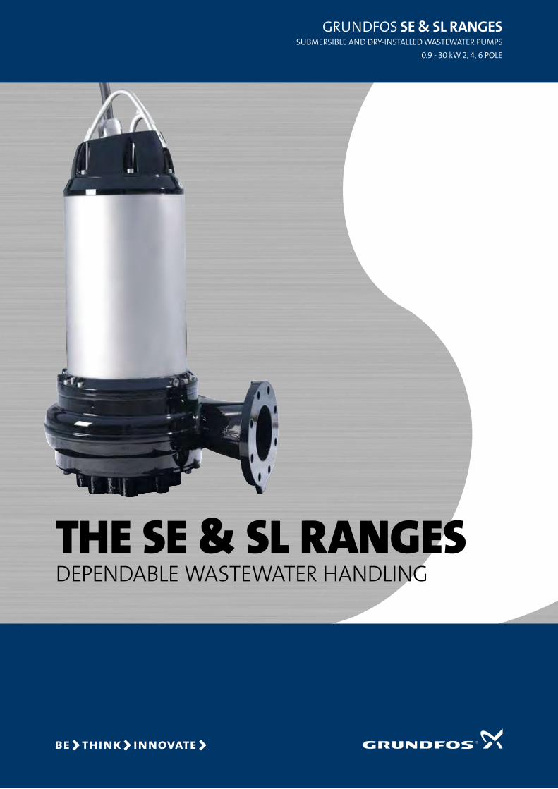
The Se & SL rangeS DepenDable wastewater hanDling
GRUNDFOS SE & SL rangES SUbmeRSible aND DRy-iNStalleD waStewateR pUmpS
0.9 - 30 kw 2, 4, 6 pOle
2
GRUNDFOS SE & SL rangES
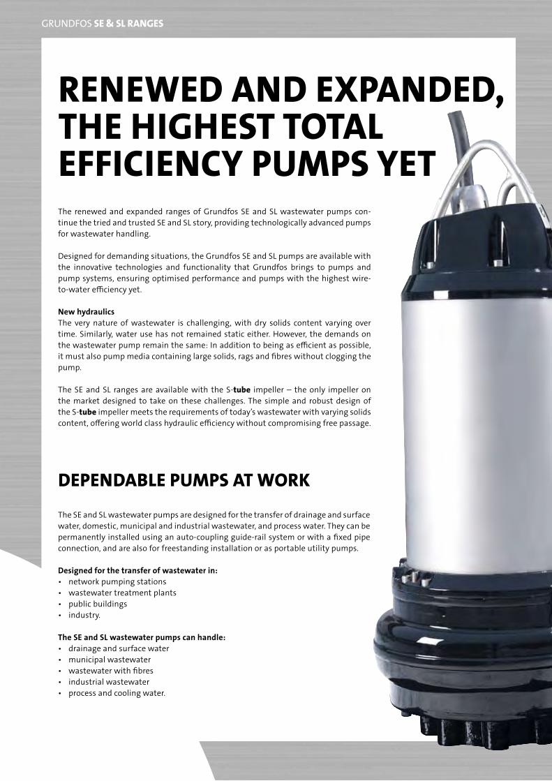
rEnEwEd and ExpandEd, thE highESt totaL EfficiEncy pumpS yEtthe renewed and expanded ranges of Grundfos Se and Sl wastewater pumps con-tinue the tried and trusted Se and Sl story, providing technologically advanced pumps for wastewater handling.
Designed for demanding situations, the Grundfos Se and Sl pumps are available with the innovative technologies and functionality that Grundfos brings to pumps and pump systems, ensuring optimised performance and pumps with the highest wire-to-water efficiency yet.
new hydraulicsthe very nature of wastewater is challenging, with dry solids content varying over time. Similarly, water use has not remained static either. However, the demands on the wastewater pump remain the same: in addition to being as efficient as possible, it must also pump media containing large solids, rags and fibres without clogging the pump.
the Se and Sl ranges are available with the S-tube impeller – the only impeller on the market designed to take on these challenges. the simple and robust design of the S-tube impeller meets the requirements of today’s wastewater with varying solids content, offering world class hydraulic efficiency without compromising free passage.
dEpEndabLE pumpS at work
the Se and Sl wastewater pumps are designed for the transfer of drainage and surface water, domestic, municipal and industrial wastewater, and process water. they can be permanently installed using an auto-coupling guide-rail system or with a fixed pipe connection, and are also for freestanding installation or as portable utility pumps.
Designed for the transfer of wastewater in:• networkpumpingstations• wastewatertreatmentplants• publicbuildings• industry.
The SE and SL wastewater pumps can handle:• drainageandsurfacewater• municipalwastewater• wastewaterwithfibres• industrialwastewater• processandcoolingwater.
3
GRUNDFOS SE & SL rangES
tEchnoLogiES for thE SE & SL rangES, by grundfoS
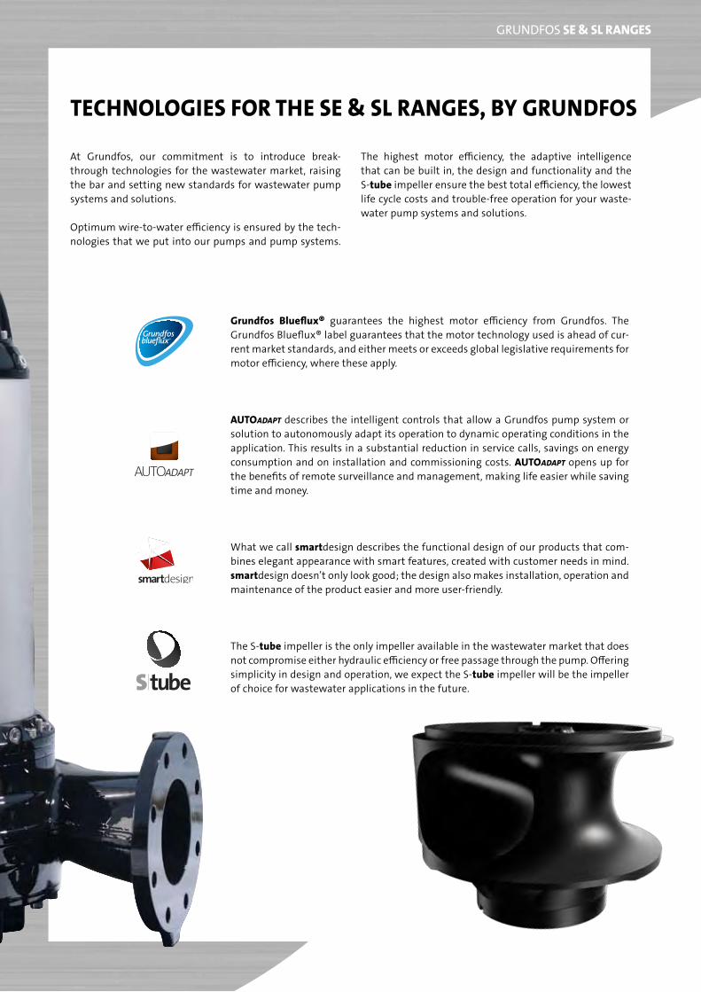
at Grundfos, our commitment is to introduce break-through technologies for the wastewater market, raising the bar and setting new standards for wastewater pump systems and solutions.
Optimum wire-to-water efficiency is ensured by the tech-nologies that we put into our pumps and pump systems.
the highest motor efficiency, the adaptive intelligence that can be built in, the design and functionality and the S-tube impeller ensure the best total efficiency, the lowest life cycle costs and trouble-free operation for your waste-water pump systems and solutions.
grundfos blueflux® guarantees the highest motor efficiency from Grundfos. the Grundfos blueflux® label guarantees that the motor technology used is ahead of cur-rent market standards, and either meets or exceeds global legislative requirements for motor efficiency, where these apply.
autoADAPT describes the intelligent controls that allow a Grundfos pump system or solution to autonomously adapt its operation to dynamic operating conditions in the application. this results in a substantial reduction in service calls, savings on energy consumption and on installation and commissioning costs. autoADAPT opens up for the benefits of remote surveillance and management, making life easier while saving time and money.
what we call smartdesign describes the functional design of our products that com-bines elegant appearance with smart features, created with customer needs in mind. smartdesign doesn’t only look good; the design also makes installation, operation and maintenance of the product easier and more user-friendly.
the S-tube impeller is the only impeller available in the wastewater market that does not compromise either hydraulic efficiency or free passage through the pump. Offering simplicity in design and operation, we expect the S-tube impeller will be the impeller of choice for wastewater applications in the future.
4
GRUNDFOS SE & SL rangES
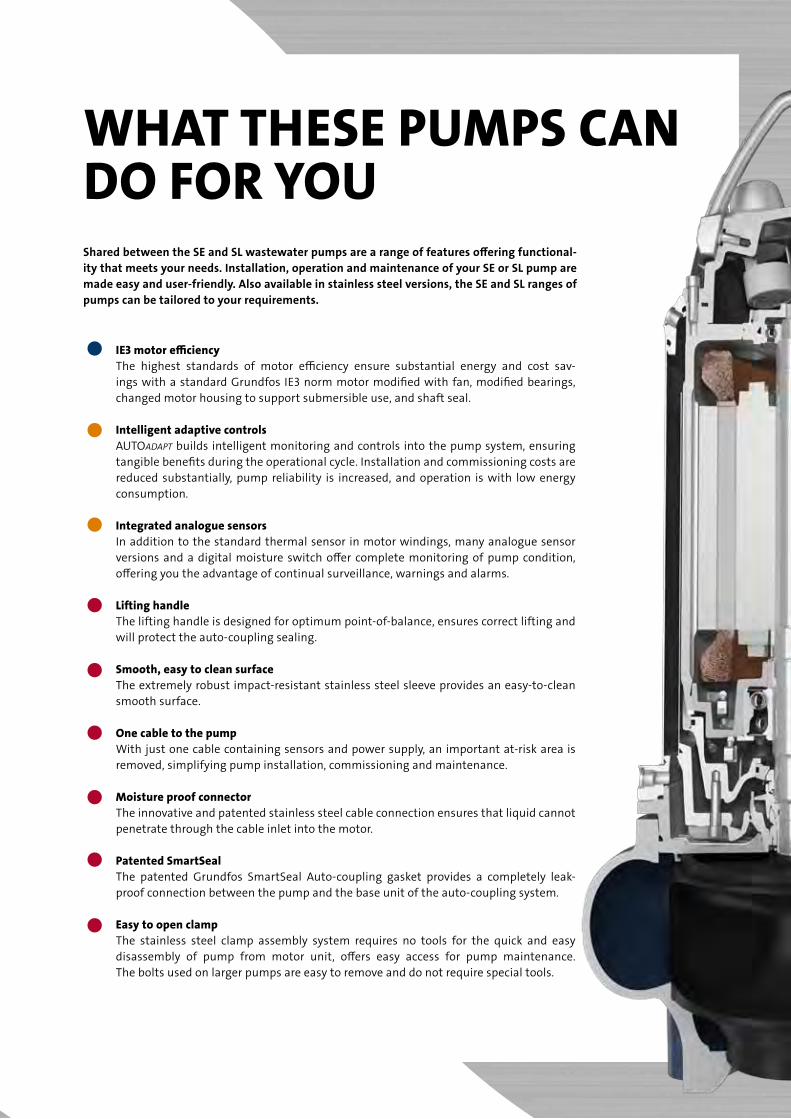
what thESE pumpS can do for youShared between the SE and SL wastewater pumps are a range of features offering functional-ity that meets your needs. Installation, operation and maintenance of your SE or SL pump are made easy and user-friendly. also available in stainless steel versions, the SE and SL ranges of pumps can be tailored to your requirements.
iE3 motor efficiency the highest standards of motor efficiency ensure substantial energy and cost sav-
ings with a standard Grundfos ie3 norm motor modified with fan, modified bearings, changed motor housing to support submersible use, and shaft seal.
intelligent adaptive controls aUtOADAPT builds intelligent monitoring and controls into the pump system, ensuring
tangible benefits during the operational cycle. installation and commissioning costs are reduced substantially, pump reliability is increased, and operation is with low energy consumption.
integrated analogue sensors in addition to the standard thermal sensor in motor windings, many analogue sensor
versions and a digital moisture switch offer complete monitoring of pump condition, offering you the advantage of continual surveillance, warnings and alarms.
Lifting handle the lifting handle is designed for optimum point-of-balance, ensures correct lifting and
will protect the auto-coupling sealing.
Smooth, easy to clean surface the extremely robust impact-resistant stainless steel sleeve provides an easy-to-clean
smooth surface.
one cable to the pump with just one cable containing sensors and power supply, an important at-risk area is
removed, simplifying pump installation, commissioning and maintenance.
moisture proof connector the innovative and patented stainless steel cable connection ensures that liquid cannot
penetrate through the cable inlet into the motor.
patented SmartSeal the patented Grundfos SmartSeal auto-coupling gasket provides a completely leak-
proof connection between the pump and the base unit of the auto-coupling system.
Easy to open clamp the stainless steel clamp assembly system requires no tools for the quick and easy
disassembly of pump from motor unit, offers easy access for pump maintenance. the bolts used on larger pumps are easy to remove and do not require special tools.
5
GRUNDFOS SE & SL rangES
optimaL impELLEr choicE:
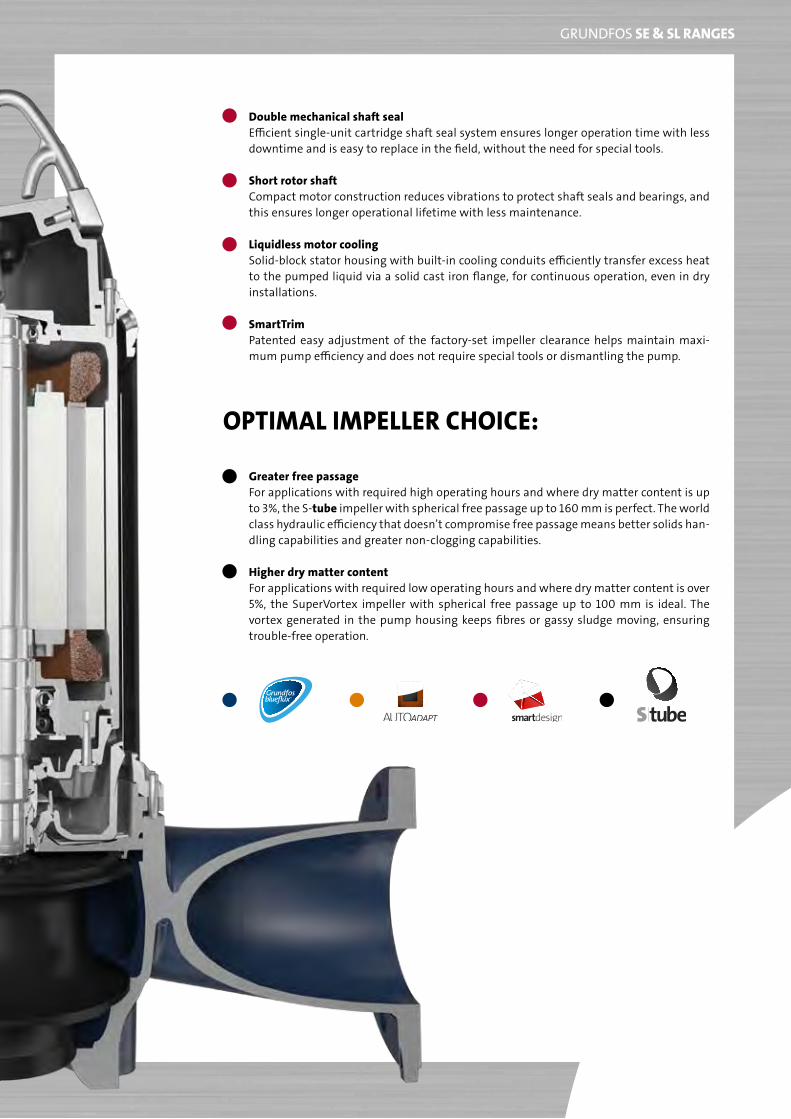
double mechanical shaft seal efficient single-unit cartridge shaft seal system ensures longer operation time with less
downtime and is easy to replace in the field, without the need for special tools.
Short rotor shaft Compact motor construction reduces vibrations to protect shaft seals and bearings, and
this ensures longer operational lifetime with less maintenance.
Liquidless motor cooling Solid-block stator housing with built-in cooling conduits efficiently transfer excess heat
to the pumped liquid via a solid cast iron flange, for continuous operation, even in dry installations.
Smarttrim patented easy adjustment of the factory-set impeller clearance helps maintain maxi-
mum pump efficiency and does not require special tools or dismantling the pump.
greater free passage For applications with required high operating hours and where dry matter content is up
to 3%, the S-tube impeller with spherical free passage up to 160 mm is perfect. the world class hydraulic efficiency that doesn’t compromise free passage means better solids han-dling capabilities and greater non-clogging capabilities.
higher dry matter content For applications with required low operating hours and where dry matter content is over
5%, the SuperVortex impeller with spherical free passage up to 100 mm is ideal. the vortex generated in the pump housing keeps fibres or gassy sludge moving, ensuring trouble-free operation.

6
GRUNDFOS SE & SL rangES
no compromiSEthe Se and Sl ranges of submersible and dry-installed wastewater pumps are available in the following versions:
SE1/SEV 1.1 - 30 kw 2, 4, 6 poleSL1/SLV 0.9 - 30 kw 2, 4, 6 pole
these heavy duty wastewater pumps offer the best total, wire-to-water efficiency yet seen with ie3 motor effi-ciency and new hydraulics, including the S-tube impeller, which offers outstanding hydraulic efficiency and excel-lent non-clogging capabilities, without compromising free passage.
the S-tube impeller developed by Grundfos includes a tube-shaped channel impeller and a pump housing around it that matches the tube shape through the entire pump.
in particular, we have succeeded in reducing vibration and resolving sealing issues. Vibration is reduced by means of a unique method for statically and dynamically balancing the impeller, and a unique and patented sealing system designed to ensure the highest reliability over time.
these pumps come with a replaceable wear ring or Smarttrim system. both systems ensure optimum impel-ler clearance and will return the pump to full efficiency when applied.
the Se and Sl wastewater pumps are designed for the transfer of drainage and surface water, domestic, munici-pal and industrial wastewater, and process water. they can be permanently installed using an auto-coupling guide-rail system or with a fixed pipe connection, and are also for freestanding installation or as portable utility pumps.
pErformancE curVES
5 7 10 15 20 30 40 50 70 100 150 200 300Q [l/s]
5
678
10
12
20
30
40
50
6070
H[m]
20 40 60 80 100 200 400 600 Q [m³/h]
50 Hz
SE&SL 1.1 - 11 kW SE&SL 9 - 30 kWTM
05 3
576
1312
7
GRUNDFOS SE & SL rangES
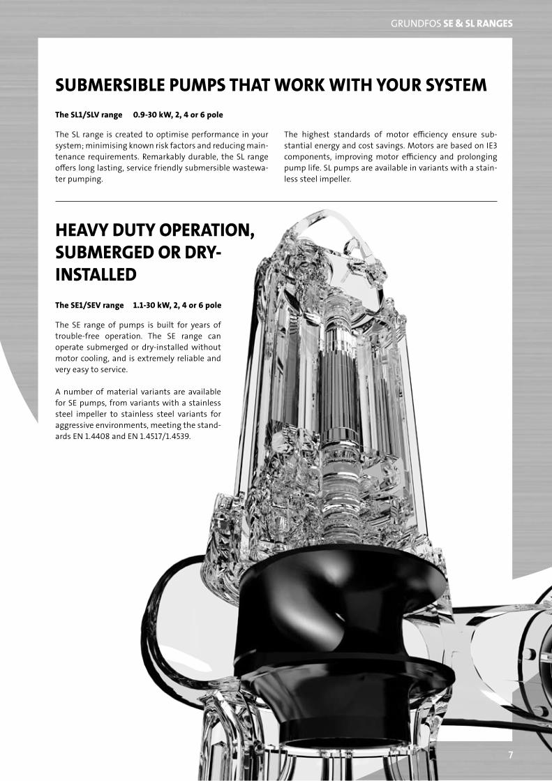
SubmErSibLE pumpS that work with your SyStEm
the Sl range is created to optimise performance in your system; minimising known risk factors and reducing main-tenance requirements. Remarkably durable, the Sl range offers long lasting, service friendly submersible wastewa-ter pumping.
the highest standards of motor efficiency ensure sub-stantial energy and cost savings. motors are based on ie3 components, improving motor efficiency and prolonging pump life. Sl pumps are available in variants with a stain-less steel impeller.
the SL1/SLV range 0.9-30 kw, 2, 4 or 6 pole
hEaVy duty opEration, SubmErgEd or dry-inStaLLEd
the Se range of pumps is built for years of trouble-free operation. the Se range can operate submerged or dry-installed without motor cooling, and is extremely reliable and very easy to service.
a number of material variants are available for Se pumps, from variants with a stainless steel impeller to stainless steel variants for aggressive environments, meeting the stand-ards eN 1.4408 and eN 1.4517/1.4539.
the SE1/SEV range 1.1-30 kw, 2, 4 or 6 pole

Being responsible is our foundationThinking ahead makes it possible
Innovation is the essence
9816
4501
/051
2/W
ATER
UTI
LITY
/106
99-D
&I
grunDfoS Holding a/SPoul Due Jensens Vej 7DK-8850 BjerringbroTel: +45 87 50 14 00
www.grundfos.comThe name Grundfos, the Grundfos logo, and the payoff Be–Think–Innovate are registrated trademarks owned by Grundfos Management A/S or Grundfos A/S, Denmark. All rights reserved worldwide.
ABC Ltd. Water Management System
Lagos Port, Nigeria
Technical Proposal‐ Water Management System Rev‐0 Page 24 of 27
Storage tanks
ABC Ltd. Water Management System
Lagos Port, Nigeria
Technical Proposal‐ Water Management System Rev‐0 Page 24 of 27
Storm Water Drainage
FOR SURFACE WATER AND
SEWERAGE APPLICATIONS
Wavin X-Stream®Foul and Stormwater Drainage System
Product Guide
Intelligent Solutions for Below Ground Projects
EPICJ344 X721
Juli 2007
TELEPHONE:+31(0)523 624 911
FAX+31(0)523 624 600
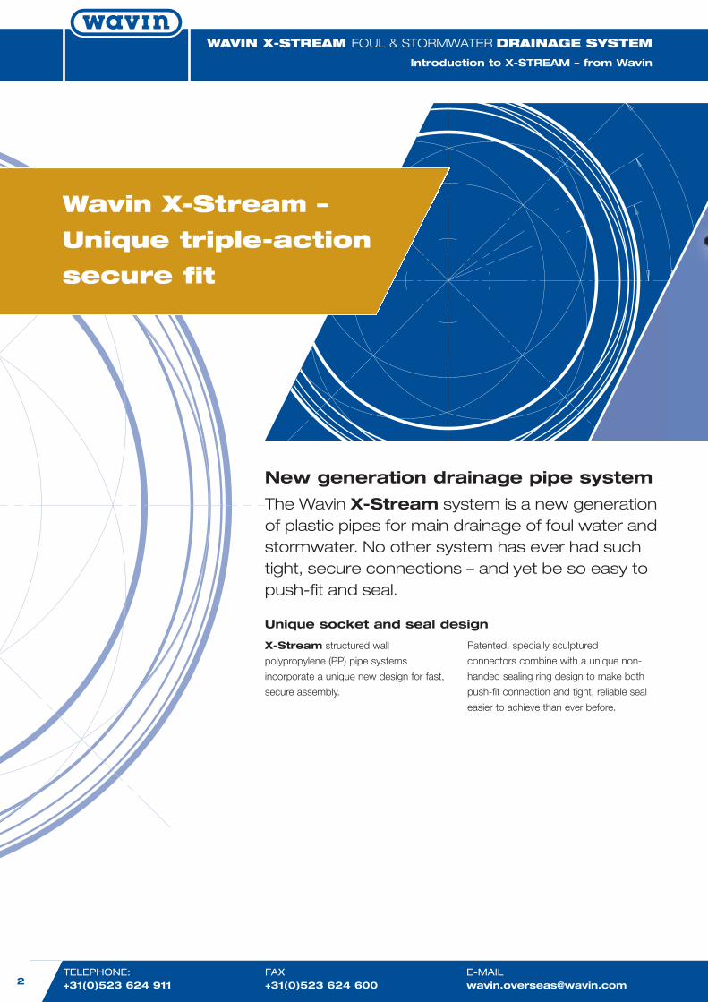
Wavin X-Stream –
Unique triple-action
secure fit
New generation drainage pipe system
The Wavin X-Stream system is a new generationof plastic pipes for main drainage of foul water andstormwater. No other system has ever had suchtight, secure connections – and yet be so easy topush-fit and seal.
X-Stream structured wall
polypropylene (PP) pipe systems
incorporate a unique new design for fast,
secure assembly.
Unique socket and seal design
Patented, specially sculptured
connectors combine with a unique non-
handed sealing ring design to make both
push-fit connection and tight, reliable seal
easier to achieve than ever before.
WAVIN X-STREAM FOUL & STORMWATERDRAINAGE SYSTEM
Introduction to X-STREAM – from Wavin
www.wavinoverseas.com 3
WAVIN X-STREAM FOUL & STORMWATERDRAINAGE SYSTEM
Product Guide: Contents
WAVIN X-Stream DRAINAGE SYSTEMIntroduction to X-STREAM from Wavin � Contents
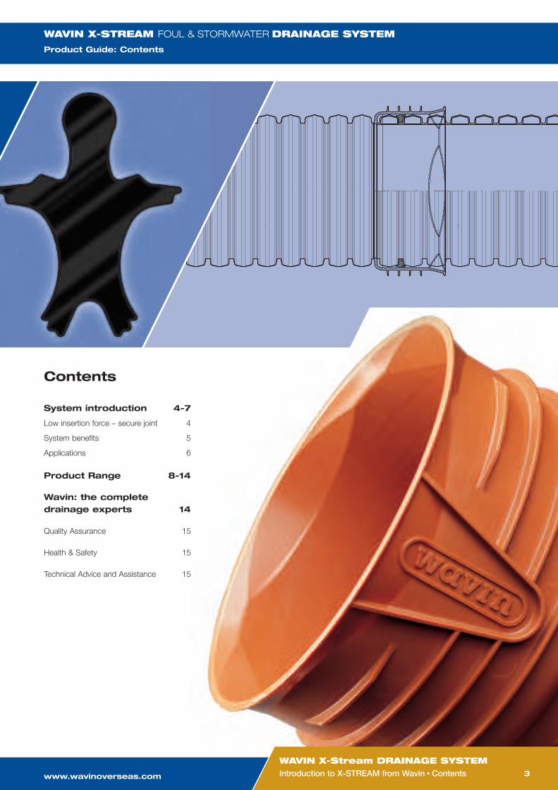
System introduction 4-7
Low insertion force – secure joint 4
System benefits 5
Applications 6
Product Range 8-14
Wavin: the completedrainage experts 14
Quality Assurance 15
Health & Safety 15
Technical Advice and Assistance 15
Contents
WAVIN X-STREAM FOUL & STORMWATERDRAINAGE SYSTEM
Product Guide: Contents
TELEPHONE:+31(0)523 624 911
FAX+31(0)523 624 600
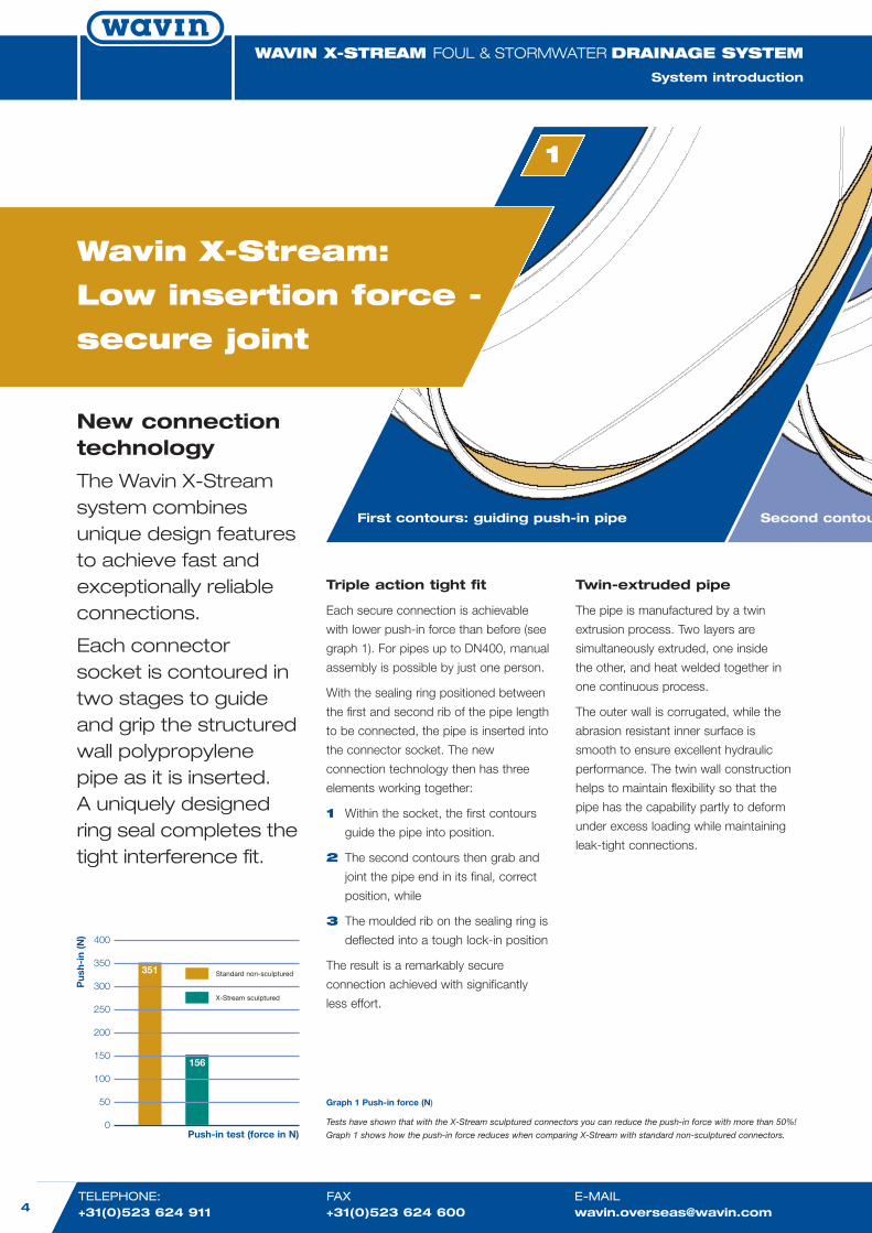
New connectiontechnology
The Wavin X-Streamsystem combinesunique design featuresto achieve fast andexceptionally reliableconnections.
Each connectorsocket is contoured intwo stages to guideand grip the structuredwall polypropylenepipe as it is inserted.A uniquely designedring seal completes thetight interference fit.
Wavin X-Stream:
Low insertion force -
secure joint
Triple action tight fit
Each secure connection is achievable
with lower push-in force than before (see
graph 1). For pipes up to DN400, manual
assembly is possible by just one person.
With the sealing ring positioned between
the first and second rib of the pipe length
to be connected, the pipe is inserted into
the connector socket. The new
connection technology then has three
elements working together:
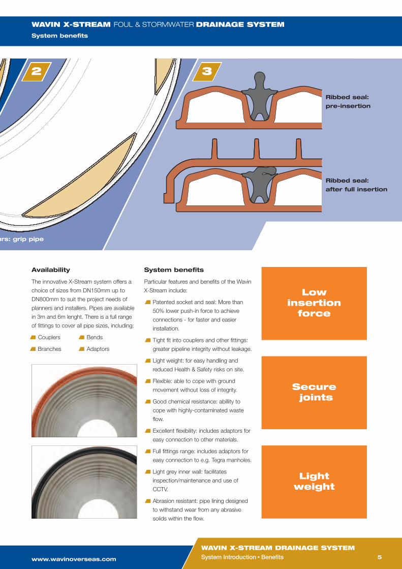
1 Within the socket, the first contours
guide the pipe into position.
2 The second contours then grab and
joint the pipe end in its final, correct
position, while
3 The moulded rib on the sealing ring is
deflected into a tough lock-in position
The result is a remarkably secure
connection achieved with significantly
less effort.
Twin-extruded pipe
The pipe is manufactured by a twin
extrusion process. Two layers are
simultaneously extruded, one inside
the other, and heat welded together in
one continuous process.
The outer wall is corrugated, while the
abrasion resistant inner surface is
smooth to ensure excellent hydraulic
performance. The twin wall construction
helps to maintain flexibility so that the
pipe has the capability partly to deform
under excess loading while maintaining
leak-tight connections.
First contours: guiding push-in pipe Second contou
1
WAVIN X-STREAM FOUL & STORMWATERDRAINAGE SYSTEM
System introduction
Graph 1 Push-in force (N)
Tests have shown that with the X-Stream sculptured connectors you can reduce the push-in force with more than 50%!
Graph 1 shows how the push-in force reduces when comparing X-Stream with standard non-sculptured connectors.
400
350
300
250
200
150
100
50
0Push-in test (force in N)
Standard non-sculptured
Pus
h-in
(N)
X-Stream sculptured
351
156
www.wavinoverseas.com 5
WAVIN X-STREAM DRAINAGE SYSTEMSystem Introduction � Benefits
Availability
The innovative X-Stream system offers a
choice of sizes from DN150mm up to
DN800mm to suit the project needs of
planners and installers. Pipes are available
in 3m and 6m lenght. There is a full range
of fittings to cover all pipe sizes, including:
Couplers Bends
Branches Adaptors
System benefits
Particular features and benefits of the Wavin
X-Stream include:
Patented socket and seal: More than
50% lower push-in force to achieve
connections - for faster and easier
installation.
Tight fit into couplers and other fittings:
greater pipeline integrity without leakage.
Light weight: for easy handling and
reduced Health & Safety risks on site.
Flexible: able to cope with ground
movement without loss of integrity.
Good chemical resistance: abillity to
cope with highly-contaminated waste
flow.
Excellent flexibility: includes adaptors for
easy connection to other materials.
Full fittings range: includes adaptors for
easy connection to e.g. Tegra manholes.
Light grey inner wall: facilitates
inspection/maintenance and use of
CCTV.
Abrasion resistant: pipe lining designed
to withstand wear from any abrasive
solids within the flow.
urs: grip pipe
Ribbed seal:
pre-insertion
Ribbed seal:
after full insertion
32
Lowinsertionforce
Lightweight
Securejoints
WAVIN X-STREAM FOUL & STORMWATERDRAINAGE SYSTEM
System benefits
TELEPHONE:+31(0)523 624 911
FAX+31(0)523 624 600
Wavin X-Stream:
For combined or
separate drainage
Applications
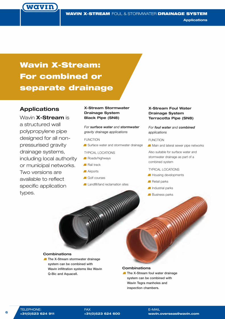
Wavin X-Stream isa structured wallpolypropylene pipedesigned for all non-pressurised gravitydrainage systems,including local authorityor municipal networks.Two versions areavailable to reflectspecific applicationtypes.
X-Stream StormwaterDrainage SystemBlack Pipe (SN8)
For surface water and stormwatergravity drainage applications
FUNCTION
Surface water and stormwater drainage
TYPICAL LOCATIONS
Roads/highways
Rail track
Airports
Golf courses
Landfill/land reclamation sites
X-Stream Foul WaterDrainage SystemTerracotta Pipe (SN8)
For foul water and combinedapplications
FUNCTION
Main and lateral sewer pipe networks
Also suitable for surface water and
stormwater drainage as part of a
combined system
TYPICAL LOCATIONS
Housing developments
Retail parks
Industrial parks
Business parks
CombinationsThe X-Stream stormwater drainage
system can be combined with
Wavin infiltration systems like Wavin
Q-Bic and Aquacell.
CombinationsThe X-Stream foul water drainage
system can be combined with
Wavin Tegra manholes and
inspection chambers.
WAVIN X-STREAM FOUL & STORMWATERDRAINAGE SYSTEM
Applications
www.wavinoverseas.com 7
WAVIN X-STREAM DRAINAGE SYSTEMApplications
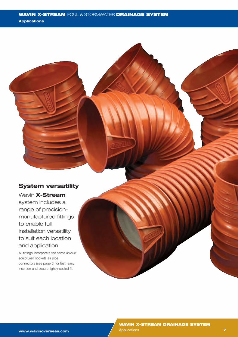
System versatility
Wavin X-Streamsystem includes arange of precision-manufactured fittingsto enable fullinstallation versatilityto suit each locationand application.All fittings incorporate the same unique
sculptured sockets as pipe
connectors (see page 5) for fast, easy
insertion and secure tightly-sealed fit.
WAVIN X-STREAM FOUL & STORMWATERDRAINAGE SYSTEM
Applications
TELEPHONE:+31(0)523 624 911
FAX+31(0)523 624 700
TELEPHONE:+31(0)523 624 911
FAX+31(0)523 624 600
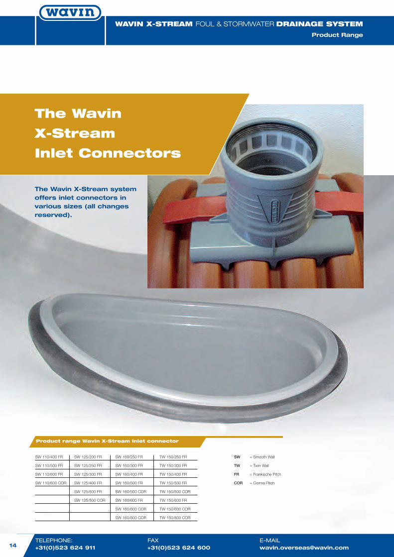
The Wavin X-Stream systemoffers inlet connectors invarious sizes (all changesreserved).
The Wavin
X-Stream
Inlet Connectors
14
WAVIN X-STREAM FOUL & STORMWATERDRAINAGE SYSTEM
Product Range
Product range Wavin X-Stream inlet connector
SW 110/400 FR SW 125/200 FR SW 160/250 FR TW 150/250 FR
SW 110/500 FR SW 125/250 FR SW 160/300 FR TW 150/300 FR
SW 110/600 FR SW 125/300 FR SW 160/400 FR TW 150/400 FR
SW 110/600 COR SW 125/400 FR SW 160/500 FR TW 150/500 FR
SW 125/500 FR SW 160/500 COR TW 150/500 COR
SW 125/500 COR SW 160/600 FR TW 150/600 FR
SW 160/600 COR TW 150/600 COR
SW 160/800 COR TW 150/800 COR
SW = Smooth Wall
TW = Twin Wall
FR = Frankische Pitch
COR = Corma Pitch
www.wavinoverseas.comwww.wavinoverseas.com
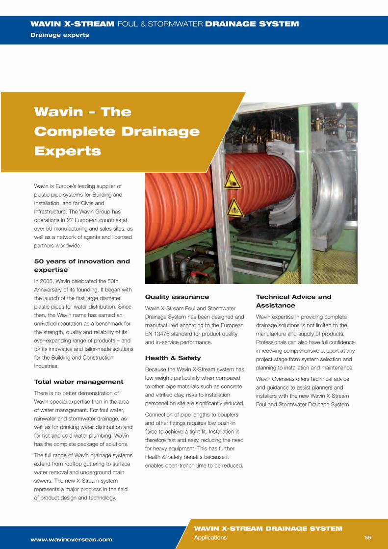
Wavin is Europe’s leading supplier of
plastic pipe systems for Building and
Installation, and for Civils and
Infrastructure. The Wavin Group has
operations in 27 European countries at
over 50 manufacturing and sales sites, as
well as a network of agents and licensed
partners worldwide.
50 years of innovation andexpertise
In 2005, Wavin celebrated the 50th
Anniversary of its founding. It began with
the launch of the first large diameter
plastic pipes for water distribution. Since
then, the Wavin name has earned an
unrivalled reputation as a benchmark for
the strength, quality and reliability of its
ever-expanding range of products – and
for its innovative and tailor-made solutions
for the Building and Construction
Industries.
Total water management
There is no better demonstration of
Wavin special expertise than in the area
of water management. For foul water,
rainwater and stormwater drainage, as
well as for drinking water distribution and
for hot and cold water plumbing, Wavin
has the complete package of solutions.
The full range of Wavin drainage systems
extend from rooftop guttering to surface
water removal and underground main
sewers. The new X-Stream system
represents a major progress in the field
of product design and technology.
Wavin – The
Complete Drainage
Experts
Quality assurance
Wavin X-Stream Foul and Stormwater
Drainage System has been designed and
manufactured according to the European
EN 13476 standard for product quality
and in-service performance.
Health & Safety
Because the Wavin X-Stream system has
low weight, particularly when compared
to other pipe materials such as concrete
and vitrified clay, risks to installation
personnel on site are significantly reduced.
Connection of pipe lengths to couplers
and other fittings requires low push-in
force to achieve a tight fit. Installation is
therefore fast and easy, reducing the need
for heavy equipment. This has further
Health & Safety benefits because it
enables open-trench time to be reduced.
Technical Advice andAssistance
Wavin expertise in providing complete
drainage solutions is not limited to the
manufacture and supply of products.
Professionals can also have full confidence
in receiving comprehensive support at any
project stage from system selection and
planning to installation and maintenance.
Wavin Overseas offers technical advice
and guidance to assist planners and
installers with the new Wavin X-Stream
Foul and Stormwater Drainage System.
15
WAVIN X-STREAM DRAINAGE SYSTEMApplications
WAVIN X-STREAM FOUL & STORMWATERDRAINAGE SYSTEMDrainage experts

Wavin Overseas B.V.Rollepaal 19, 7701 BRP.O. Box 159, 7700 ADDedemsvaart, The NetherlandsPhone: +31/523-624911Fax: +31/523-624600E-mail: [email protected]
Wavin X-Stream®Foul and Stormwater Drainage System
Product Guide
All information in contained in this literature is given in good faith. The user should, however check that the productis suitable for purpose, in the application for which it shall be used. Please ensure compliance with all health andsafety requirements. Whilst continuing its programme of continuous development, Wavin Overseas B.V. reserves theright to modify or extend any published information without any prior notification. No responsibility can be acceptedfor any error, omissions or incorrect assumptions.
The complete drainage expertsWavin provides complete solutions for drainage fromrooftop to main sewers below ground, including:
Above Ground ProjectsRainwater guttering and drainage
Soil and waste drainage
Below Ground ProjectsSurface water drainage
Foul water drainage: gravity and pumped sewers
Stormwater attenuation and infiltration
www.wavinoverseas.com

ABC Ltd. Water Management System
Lagos Port, Nigeria
Technical Proposal‐ Water Management System Rev‐0 Page 24 of 27
Inspection Chambers
September 2008
System Data SheetWavin Tegra 315 WAJ
INSPECTION CHAMBER
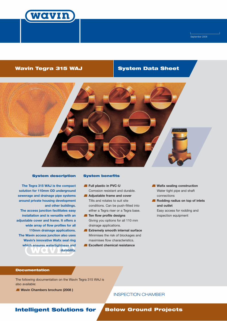
System description
The Tegra 315 WAJ is the compact
solution for 110mm OD underground
sewerage and drainage pipe systems
around private housing development
and other buildings.
The access junction facilitates easy
installation and is versatile with an
adjustable cover and frame. It offers a
wide array of flow profiles for all
110mm drainage applications.
The Wavin access junction also uses
Wavin’s innovative Wafix seal ring
which ensures watertightness and
durability.
System benefits
Full plastic in PVC-U
Corrosion resistant and durable.
Adjustable frame and cover
Tilts and rotates to suit site
conditions. Can be push-fitted into
either a Tegra riser or a Tegra base.
Ten flow profile designs
Giving you options for all 110 mm
drainage applications.
Extremely smooth internal surface
Minimises the risk of blockages and
maximises flow characteristics.
Excellent chemical resistance
Wafix sealing construction
Water tight pipe and shaft
connections
Rodding radius on top of inlets
and outlet
Easy access for rodding and
inspection equipment
Intelligent Solutions for Below Ground Projects
Documentation
The following documentation on the Wavin Tegra 315 WAJ isalso available:
Wavin Chambers brochure (2008 )
WAvin ED Leaflet Tegra 315.qxd:A4 26-02-2009 16:00 Pagina 1
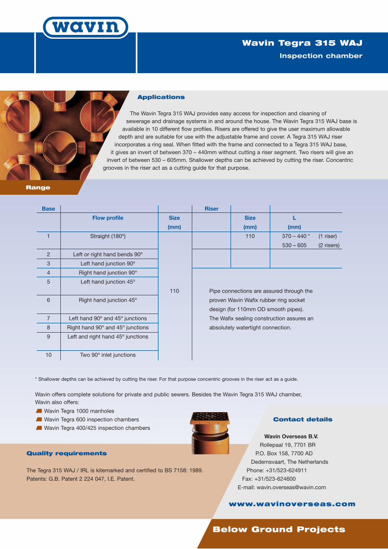
Applications
The Wavin Tegra 315 WAJ provides easy access for inspection and cleaning ofsewerage and drainage systems in and around the house. The Wavin Tegra 315 WAJ base isavailable in 10 different flow profiles. Risers are offered to give the user maximum allowabledepth and are suitable for use with the adjustable frame and cover. A Tegra 315 WAJ riserincorporates a ring seal. When fitted with the frame and connected to a Tegra 315 WAJ base,it gives an invert of between 370 – 440mm without cutting a riser segment. Two risers will give aninvert of between 530 – 605mm. Shallower depths can be achieved by cutting the riser. Concentricgrooves in the riser act as a cutting guide for that purpose.
Below Ground Projects
Wavin Tegra 315 WAJ
Inspection chamber
Quality requirements
The Tegra 315 WAJ / IRL is kitemarked and certified to BS 7158: 1989.
Patents: G.B. Patent 2 224 047, I.E. Patent.
Contact details
Wavin Overseas B.V.
Rollepaal 19, 7701 BR
P.O. Box 158, 7700 AD
Dedemsvaart, The Netherlands
Phone: +31/523-624911
Fax: +31/523-624600
E-mail: [email protected]
www.wavinoverseas.com
Range
* Shallower depths can be achieved by cutting the riser. For that purpose concentric grooves in the riser act as a guide.
Wavin offers complete solutions for private and public sewers. Besides the Wavin Tegra 315 WAJ chamber,Wavin also offers:
Wavin Tegra 1000 manholes
Wavin Tegra 600 inspection chambers
Wavin Tegra 400/425 inspection chambers
Base Riser
Flow profile Size Size L
(mm) (mm) (mm)
1 Straight (180º) 110 370 – 440 * (1 riser)
530 – 605 (2 risers)
2 Left or right hand bends 90º
3 Left hand junction 90º
4 Right hand junction 90º
5 Left hand junction 45º
110
6 Right hand junction 45º
7 Left hand 90º and 45º junctions
8 Right hand 90º and 45º junctions
9 Left and right hand 45º junctions
10 Two 90º inlet junctions
S
Pipe connections are assured through the
proven Wavin Wafix rubber ring socket
design (for 110mm OD smooth pipes).
The Wafix sealing construction assures an
absolutely watertight connection.
WAvin ED Leaflet Tegra 315.qxd:A4 26-02-2009 16:00 Pagina 2

ABC Ltd. Water Management System
Lagos Port, Nigeria
Technical Proposal‐ Water Management System Rev‐0 Page 24 of 27
Manholes

September 2008
System Data SheetWavin Tegra 600
INSPECTION CHAMBER
System description
The Wavin Tegra 600 is a 600mmpolypropylene (PP) inspection
chamber for use in public sewers asaccess for inspection, cleaning and
maintenance. This revolutionarychamber offers advantages such as
tight fitting, easy handling, shorterinstallation time, less maintenanceresulting in cost effectiveness that
plastic provides in contrast totraditional materials. The flexible
connections at the base allow a 15ºvariance in angle of the connected
pipe. Wavin Tegra 600 is a uniquechamber and one of the most robust
types when used with a corrugatedshaft. Its performance is unaffected by
the quality of the installation.
System benefits
Adjustable pipe connectors
Allowing a 15º free angular deflection
of the connected pipe.
Corrugated single wall shaft
Provides excellent resistance to
heavy traffic loads and ground
movement.
Low weight
Easy to install, no cranes needed.
Base connections in 6 different
flow profiles
The base is available in 6 different
flow profiles. All profiles have
adjustable base connections.
Adjustable cover
Easy to install and adjust grating and
cover to street surface level.
Simple and reliable in-situ
connection possible in the shaft
Additional pipe connections can be
made.
Excellent chemical and corrosion
resistance
Non-porous, smooth internal
surface
The excellent design of the flow
profile prevents building up of
deposits and blockages. The
chamber is easy to clean, low
maintenance is required.
Intelligent Solutions for Below Ground Projects
Documentation
The following documentation on the Wavin Tegra 600 is alsoavailable:
Wavin Tegra 1000 and Tegra 600,
Product and Technical Guide (2005)
WAvin ED Leaflet Tegra 600.qxd:A4 26-02-2009 16:01 Pagina 1
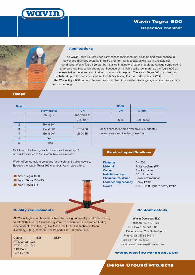
Applications
The Wavin Tegra 600 provides easy access for inspection, cleaning and maintenance insewer and drainage systems in traffic and non-traffic areas, as well as in unstable soil
conditions. Wavin Tegra 600 can be installed in narrow situations, a big advantage compared tolarge concrete inspection chambers. Because of its high quality raw material, the Tegra 600 can
be installed in the street, also in direct contact with asphalt. The Wavin Tegra 600 chamber canwithstand up to 25 metric tons wheel load (2.5 x testing load for traffic class SLW60).
The Wavin Tegra 600 can also be used as a sandtrap in rainwater discharge systems and as a cham-ber for metering.
Below Ground Projects
Wavin Tegra 600
Inspection chamber
Base Shaft
Flow profile DN DN L (mm)
1 Straight 160/200/250
315/400* 600 700 - 6000
2 Bend 30º
3 Bend 60º 160/200
4 Bend 90º 250/315
5 Tee
6 Cross
Many accessories area available, e.g. adapter,
covers, seals and in-situ connectors.
Contact details
Wavin Overseas B.V.
Rollepaal 19, 7701 BR
P.O. Box 158, 7700 AD
Dedemsvaart, The Netherlands
Phone: +31/523-624911
Fax: +31/523-624600
E-mail: [email protected]
www.wavinoverseas.com
Range
Each flow profile has adjustable pipe connections (except *).
An angular variance of 7.5º in each direction is possible.
Wavin offers complete solutions for private and public sewers.Besides the Wavin Tegra 600 chamber, Wavin also offers:
Wavin Tegra 1000
Wavin Tegra 400/425
Wavin Tegra 315
Product specifications
Diameter DN 600Material Polypropylene (PP)Colour Black/coral redInstallation depth 0.8 – 5 metersChemical resistance Sewer environmentLoad bearing capacity Heavy trafficCovers A15 – F900, light to heavy traffic
Quality requirements
All Wavin Tegra chambers are subject to testing and quality control accordingto ISO 9002 Quality Assurance system. The chambers are also certified byindependent institutes, e.g. Deutsche Institut für Bautechnik in Bonn(Germany), DTI (Denmark), TIN (Poland), CSTB (France), etc.
CoBRT 7 Inital IBDiMAT/2000-02-1025AT/2001-04-1049DIBT Berlinz-42.1 - 338
WAvin ED Leaflet Tegra 600.qxd:A4 26-02-2009 16:01 Pagina 2

January 2009 version 1
System Data SheetWavin Tegra 1000
MANHOLE
System description
The Wavin Tegra 1000 manhole is areal breakthrough in sewer technology,presenting the “missing link” to a total
plastic sewer system: the full size1000mm manhole.
The advanced design of the ribstructure and shape of the cone gives
the required strength and stabilityagainst heavy traffic load.
System benefits
Complete plastic in HDPE
Corrosion resistant, durable.
90% lighter than concrete
manholes
Easy to handle and install.
Resistant to heavy traffic load
Simple and reliable in-situ
connections
Additional pipe connections can be
made in the shaft
Adjustable height
The shaft can easily be cut every
12.5 cm to adapt the manhole to the
required installation depth.
Lower installation costs
Due to the adjustable height and the
easy connection of extra pipes.
Completely tight
Due to the rubber ring sealing.
Variety of installation depths
By joining shafts, installation depths
can range from 1 to 6 meters, with a
maximum groundwater level of 5m.
Excellent chemical resistance
Tegra 1000 is made from PE, which is
resistant to a great number of
chemical agents.
Intelligent Solutions for Below Ground Projects
Documentation
The following documentation on the Wavin Tegra 1000 is alsoavailable:
Wavin Tegra 1000 and Tegra 600,
Product and Technical Guide (2005)
WAvin ED Leaflet Tegra 1000.qxd:A4 26-02-2009 16:02 Pagina 1
Applications
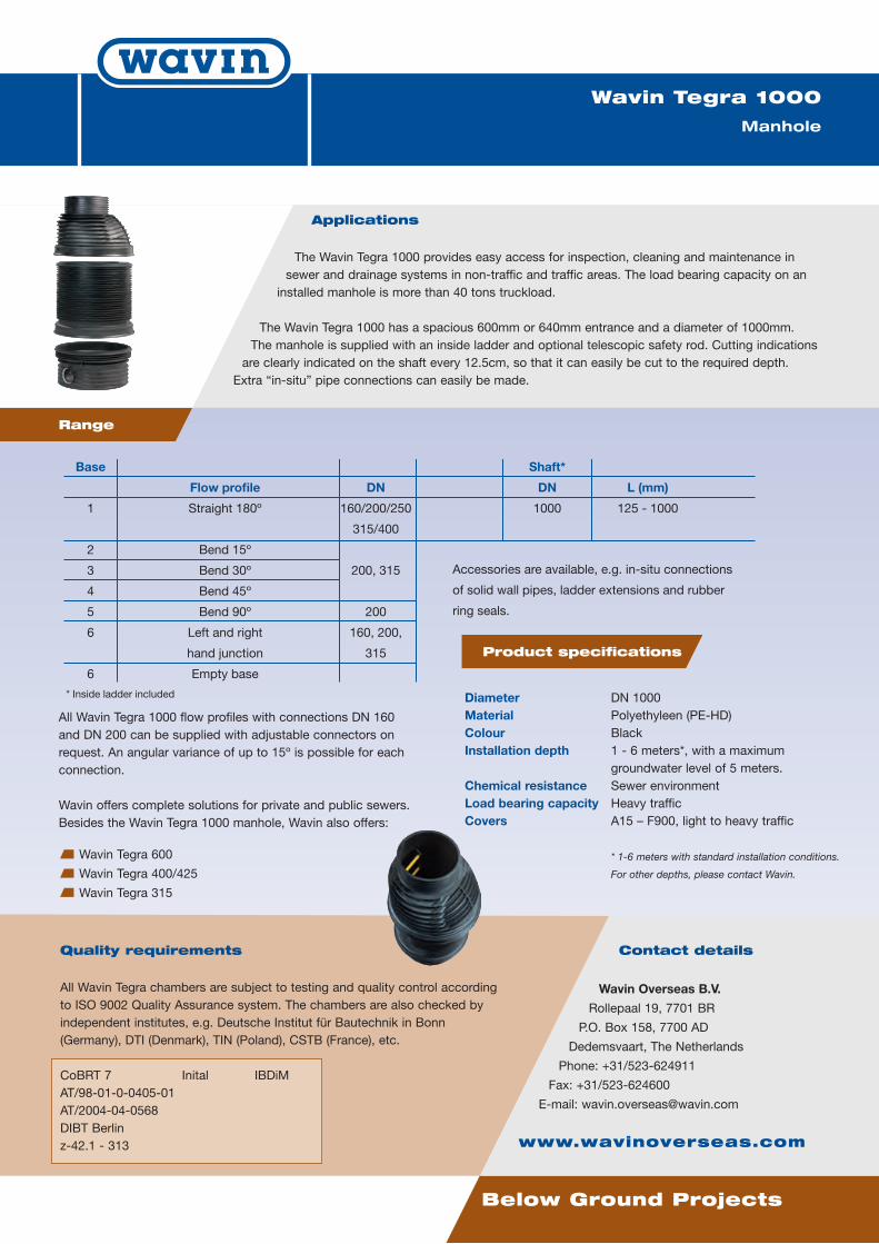
The Wavin Tegra 1000 provides easy access for inspection, cleaning and maintenance insewer and drainage systems in non-traffic and traffic areas. The load bearing capacity on aninstalled manhole is more than 40 tons truckload.
The Wavin Tegra 1000 has a spacious 600mm or 640mm entrance and a diameter of 1000mm.The manhole is supplied with an inside ladder and optional telescopic safety rod. Cutting indicationsare clearly indicated on the shaft every 12.5cm, so that it can easily be cut to the required depth.Extra “in-situ” pipe connections can easily be made.
Wavin Tegra 1000
Manhole
Range
Base Shaft*
Flow profile DN DN L (mm)
1 Straight 180º 160/200/250 1000 125 - 1000
315/400
2 Bend 15º
3 Bend 30º 200, 315
4 Bend 45º
5 Bend 90º 200
6 Left and right 160, 200,
hand junction 315
6 Empty base
Accessories are available, e.g. in-situ connections
of solid wall pipes, ladder extensions and rubber
ring seals.
* Inside ladder included
All Wavin Tegra 1000 flow profiles with connections DN 160and DN 200 can be supplied with adjustable connectors onrequest. An angular variance of up to 15º is possible for eachconnection.
Wavin offers complete solutions for private and public sewers.Besides the Wavin Tegra 1000 manhole, Wavin also offers:
Wavin Tegra 600
Wavin Tegra 400/425
Wavin Tegra 315
Product specifications
Diameter DN 1000Material Polyethyleen (PE-HD)Colour BlackInstallation depth 1 - 6 meters*, with a maximum
groundwater level of 5 meters.Chemical resistance Sewer environmentLoad bearing capacity Heavy trafficCovers A15 – F900, light to heavy traffic
* 1-6 meters with standard installation conditions.
For other depths, please contact Wavin.
Below Ground Projects
Contact details
Wavin Overseas B.V.
Rollepaal 19, 7701 BR
P.O. Box 158, 7700 AD
Dedemsvaart, The Netherlands
Phone: +31/523-624911
Fax: +31/523-624600
E-mail: [email protected]
www.wavinoverseas.com
Quality requirements
All Wavin Tegra chambers are subject to testing and quality control accordingto ISO 9002 Quality Assurance system. The chambers are also checked byindependent institutes, e.g. Deutsche Institut für Bautechnik in Bonn(Germany), DTI (Denmark), TIN (Poland), CSTB (France), etc.
CoBRT 7 Inital IBDiMAT/98-01-0-0405-01AT/2004-04-0568DIBT Berlinz-42.1 - 313
WAvin ED Leaflet Tegra 1000.qxd:A4 26-02-2009 16:02 Pagina 2
ABC Ltd. Water Management System
Lagos Port, Nigeria
Technical Proposal‐ Water Management System Rev‐0 Page 24 of 27
Sewer Pipes
September 2008
System Data SheetWavin PVC Sewer Systems
PVC SEWER SYSTEMS
System description
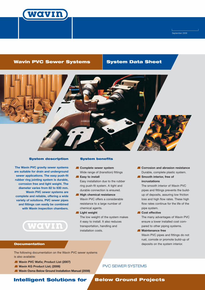
The Wavin PVC gravity sewer systemsare suitable for drain and undergroundsewer applications. The easy push-fitrubber ring jointing system is durable,corrosion free and light weight. Thediameter varies from 82 to 630 mm.
Wavin PVC sewer systems arecomplete and reliable, offering a widevariety of solutions. PVC sewer pipesand fittings can easily be combinedwith Wavin inspection chambers.
System benefits
Complete sewer system
Wide range of (transition) fittings
Easy to install
Easy installation due to the rubber
ring push-fit system. A tight and
durable connection is ensured.
High chemical resistance
Wavin PVC offers a considerable
resistance to a large number of
chemical agents.
Light weight
The low weight of the system makes
it easy to install. It also reduces
transportation, handling and
installation costs.
Corrosion and abrasion resistance
Durable, complete plastic system.
Smooth interior, free of
incrustations
The smooth interior of Wavin PVC
pipes and fittings prevents the build-
up of deposits, assuring low friction
loss and high flow rates. These high
flow rates continue for the life of the
pipe system.
Cost effective
The many advantages of Wavin PVC
ensure a lower installed cost com-
pared to other piping systems.
Maintenance free
Wavin PVC pipes and fittings do not
rust, corrode or promote build-up of
deposits on the system interior.
Intelligent Solutions for Below Ground Projects
Documentation
The following documentation on the Wavin PVC sewer systemsis also available:
Wavin PVC Wafix; Product List (2007)
Wavin KG Product List; (2006)
Wavin Osma Below Ground Installation Manual (2008)
Applications
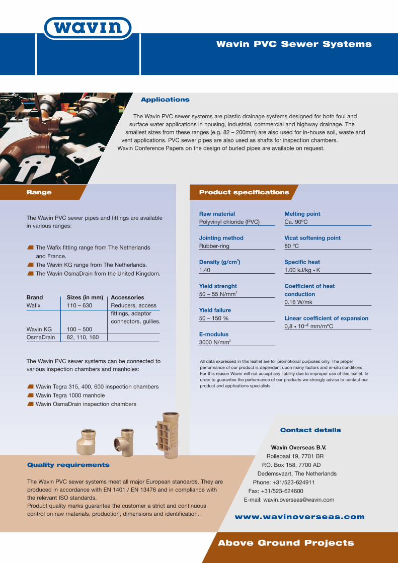
The Wavin PVC sewer systems are plastic drainage systems designed for both foul andsurface water applications in housing, industrial, commercial and highway drainage. The
smallest sizes from these ranges (e.g. 82 – 200mm) are also used for in-house soil, waste andvent applications. PVC sewer pipes are also used as shafts for inspection chambers.
Wavin Conference Papers on the design of buried pipes are available on request.
Above Ground Projects
Wavin PVC Sewer Systems
Raw materialPolyvinyl chloride (PVC)
Jointing methodRubber-ring
Density (g/cm3)1.40
Yield strenght50 – 55 N/mm2
Yield failure50 – 150 %
E-modulus3000 N/mm2
Melting pointCa. 90ºC
Vicat softening point80 ºC
Specific heat1.00 kJ/kg • K
Coefficient of heatconduction0.16 W/mk
Linear coefficient of expansion0,8 • 10-4 mm/mºC
Quality requirements
The Wavin PVC sewer systems meet all major European standards. They areproduced in accordance with EN 1401 / EN 13476 and in compliance withthe relevant ISO standards.Product quality marks guarantee the customer a strict and continuouscontrol on raw materials, production, dimensions and identification.
Contact details
Wavin Overseas B.V.
Rollepaal 19, 7701 BR
P.O. Box 158, 7700 AD
Dedemsvaart, The Netherlands
Phone: +31/523-624911
Fax: +31/523-624600
E-mail: [email protected]
www.wavinoverseas.com
Product specificationsRange
The Wavin PVC sewer pipes and fittings are availablein various ranges:
The Wafix fitting range from The Netherlands
and France.
The Wavin KG range from The Netherlands.
The Wavin OsmaDrain from the United Kingdom.
Brand Sizes (in mm) AccessoriesWafix 110 – 630 Reducers, access
fittings, adaptorconnectors, gullies.
Wavin KG 100 – 500OsmaDrain 82, 110, 160
The Wavin PVC sewer systems can be connected tovarious inspection chambers and manholes:
Wavin Tegra 315, 400, 600 inspection chambers
Wavin Tegra 1000 manhole
Wavin OsmaDrain inspection chambers
All data expressed in this leaflet are for promotional purposes only. The properperformance of our product is dependent upon many factors and in-situ conditions.For this reason Wavin will not accept any liability due to improper use of this leaflet. Inorder to guarantee the performance of our products we strongly advise to contact ourproduct and applications specialists.

ABC Ltd. Water Management System
Lagos Port, Nigeria
Technical Proposal‐ Water Management System Rev‐0 Page 24 of 27
Pressure Pipes

January 2009 version 1
System Data SheetWavin PE pressure pipes
PE PRESSURE PIPES
System description
Wavin offers a comprehensive rangeof PE pressure pipe systems designedfor potable water, gas and industrialapplications and rising mains. WavinPE pressure pipes are manufactured
from high-density polyethylene, PE100.PE is especially suitable for pressureapplications due to the high flexibility
level. PE also guarantees impactresistance even at low temperatures.
System benefits
High reliability and proven service
performance
PE is the preferred choice,
particularly in buried pipe systems
like gas distribution systems.
High impact resistance
Wavin PE shows an enormous resist-
ance against surge and fatigue.
Resistance to low temperatures
Due to its high ductility, toughness
and elasticity, Wavin PE gives no
problems during installation and
operation at low temperatures.
Excellent chemical resistance
Wavin PE is resistant to a large
number of chemical agents.
Smoothness of bore
Optimal flow through smooth
interiors.
Ease of assembly
Because of the good fuse-ability and
flexibility of PE, long lengths can be
assembled outside the (narrow)
trench. The fused joints are strong
and highly reliable. number of
chemical agents
Intelligent Solutions for Pressure Pipe Projects
Documentation
The following documentation on the Wavn PE pressure pipes is
available:
Wavin PE pressure pipe - Product and Technical
Guide (2006)
Wavin PE pipe fittings – System Data Sheet (2008)
WAvin ED Leaflet PE Pressure Pipes.qxd:A4 26-02-2009 15:40 Pagina 1
Applications
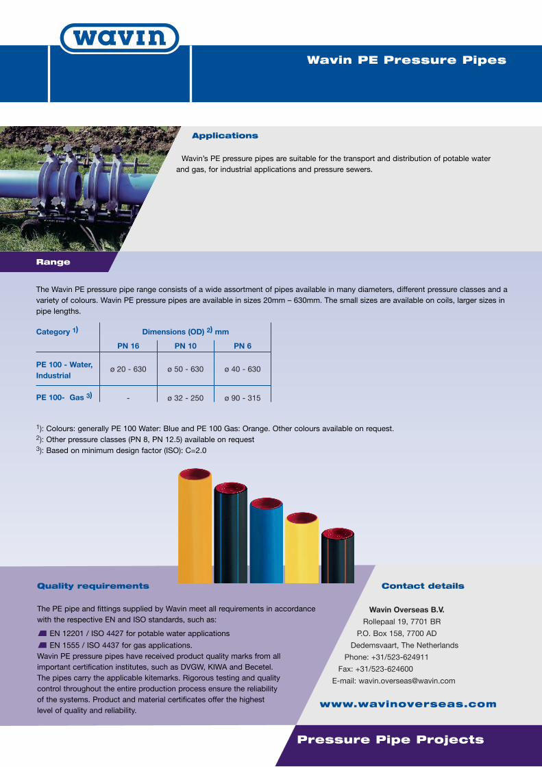
Wavin’s PE pressure pipes are suitable for the transport and distribution of potable waterand gas, for industrial applications and pressure sewers.
Pressure Pipe Projects
Wavin PE Pressure Pipes
Quality requirements
The PE pipe and fittings supplied by Wavin meet all requirements in accordancewith the respective EN and ISO standards, such as:
EN 12201 / ISO 4427 for potable water applications
EN 1555 / ISO 4437 for gas applications.Wavin PE pressure pipes have received product quality marks from allimportant certification institutes, such as DVGW, KIWA and Becetel.The pipes carry the applicable kitemarks. Rigorous testing and qualitycontrol throughout the entire production process ensure the reliabilityof the systems. Product and material certificates offer the highestlevel of quality and reliability.
Contact details
Wavin Overseas B.V.
Rollepaal 19, 7701 BR
P.O. Box 158, 7700 AD
Dedemsvaart, The Netherlands
Phone: +31/523-624911
Fax: +31/523-624600
E-mail: [email protected]
www.wavinoverseas.com
The Wavin PE pressure pipe range consists of a wide assortment of pipes available in many diameters, different pressure classes and avariety of colours. Wavin PE pressure pipes are available in sizes 20mm – 630mm. The small sizes are available on coils, larger sizes inpipe lengths.
Range
Category 1)
PE 100 - Water,Industrial
PE 100- Gas 3)
Dimensions (OD) 2) mm
PN 16
1): Colours: generally PE 100 Water: Blue and PE 100 Gas: Orange. Other colours available on request.2): Other pressure classes (PN 8, PN 12.5) available on request3): Based on minimum design factor (ISO): C=2.0
PN 10 PN 6
ø 20 - 630 ø 50 - 630 ø 40 - 630
- ø 32 - 250 ø 90 - 315
WAvin ED Leaflet PE Pressure Pipes.qxd:A4 26-02-2009 15:40 Pagina 2
September 2008
System Data SheetWavin PE pipe fittings
PE PIPE FITTINGS
System description
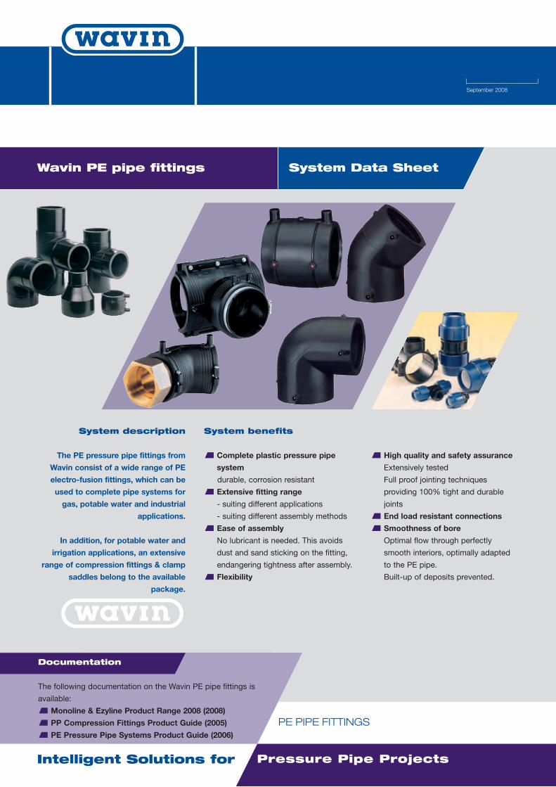
The PE pressure pipe fittings from
Wavin consist of a wide range of PE
electro-fusion fittings, which can be
used to complete pipe systems for
gas, potable water and industrial
applications.
In addition, for potable water and
irrigation applications, an extensive
range of compression fittings & clamp
saddles belong to the available
package.
System benefits
Complete plastic pressure pipe
system
durable, corrosion resistant
Extensive fitting range
- suiting different applications
- suiting different assembly methods
Ease of assembly
No lubricant is needed. This avoids
dust and sand sticking on the fitting,
endangering tightness after assembly.
Flexibility
High quality and safety assurance
Extensively tested
Full proof jointing techniques
providing 100% tight and durable
joints
End load resistant connections
Smoothness of bore
Optimal flow through perfectly
smooth interiors, optimally adapted
to the PE pipe.
Built-up of deposits prevented.
Intelligent Solutions for Pressure Pipe Projects
Documentation
The following documentation on the Wavin PE pipe fittings is
available:
Monoline & Ezyline Product Range 2008 (2008)
PP Compression Fittings Product Guide (2005)
PE Pressure Pipe Systems Product Guide (2006)
WAvin ED Leaflet PE Pipe Fittings.qxd:A4 26-02-2009 15:38 Pagina 1

Applications
The PE electrofusion fitting range is suitable for all sorts of applications in combination with
PE pressure pipelines. Distinction can be made between two ranges of fittings:
Monoline fittings (40V): all-round compatible with the majority of fusion machines in the market.
Ezyline fittings (10A): typically suited for working in narrow (industrial and civils) conditions.
The compression fitting range is a quick assembly system typically for potable water use.
Pressure Pipe Projects
Wavin PE pipe fittings
PE pipe fittings
Quality requirements
The PE pressure pipe fittings supplied by Wavin meet all requirements in
accordance with the respective EN and ISO standards for water and gas
applications, respectively: EN 12201-3/ ISO 4427 and EN1555-3/ISO 4437.
Rigorous testing and quality control throughout the entire production
process ensure the reliability of the fittings.
Contact details
Wavin Overseas B.V.
Rollepaal 19, 7701 BR
P.O. Box 158, 7700 AD
Dedemsvaart, The Netherlands
Phone: +31/523-624911
Fax: +31/523-624600
E-mail: [email protected]
www.wavinoverseas.com
Range
Category
Monolinefitting
Ezylinefitting1)
Compressionfitting
Jointing methods
Butt fusionElectro fusion
Electro fusion
Push fit version
Clamp version
Fitting type
couplers tees, transitions elbows, end caps clamp saddles
PN 16 PN 10
ø 20 - ø 500
ø 20 - ø 225 ø 250 - ø 315
ø 16 - ø 63 ø 75 - ø 110
ø 20 - ø 500
ø 20 - ø 63
ø 16 - ø 63 ø 75 - ø 110
ø 110 - ø 500
ø 40 - ø 225
PN 16 PN 10 PN 16 PN 10
ø 160 2)
1): available in short (“I”) and long (“Ll”) version2): ø 200 in PN 6; ø 225- 315 in PN 4
Wavin Overseas B.V. offers all tools, fusion machines and accessoriesfor a smooth installation of a complete system.
WAvin ED Leaflet PE Pipe Fittings.qxd:A4 26-02-2009 15:39 Pagina 2
ABC Ltd. Water Management System
Lagos Port, Nigeria
Technical Proposal‐ Water Management System Rev‐0 Page 24 of 27
Valves
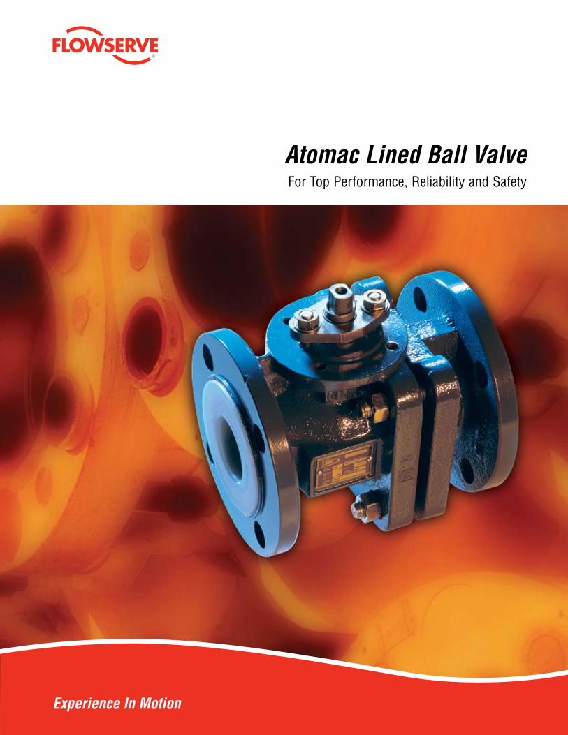
Experience In Motion
Atomac Lined Ball ValveFor Top Performance, Reliability and Safety
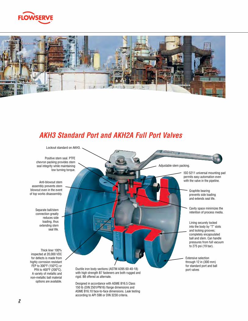
�
Ductile iron body sections (ASTM A395 60-40-18) with high strength B7 fasteners are both rugged and rigid. B8 offered as alternate.
Designed in accordance with ASME B16.5 Class 150 lb (DIN 2501⁄PN16) flange dimensions and ASME B16.10 face-to-face dimensions. Leak testing according to API 598 or DIN 3230 criteria.
Anti-blowout stem assembly prevents stem
blowout even in the event of top works disassembly.
Positive stem seal. PTFE chevron packing provides stem seal integrity while maintaining
low turning torque.
Separate ball/stem connection greatly
reduces side loading, thus
extending stem seal life.
Lockout standard on AKH3.
Adjustable stem packing.
Graphite bearing prevents side loading and extends seal life.
ISO 5211 universal mounting pad permits easy automation even with the valve in the pipeline.
Lining securely locked into the body by “T” slots and locking grooves; completely encapsulated ball and stem. Can handle pressures from full vacuum to 275 psi (19 bar).
Cavity space minimizes the retention of process media.
Extensive selection through 12 in (300 mm) for standard port and ball port valves
Thick liner 100% inspected at 20,000 VDC for defects is made from
highly corrosion resistant FEP to 300°F (150°C) or
PFA to 400°F (200°C). A variety of metallic and
non-metallic ball material options are available.
AKH3 Standard Port and AKH�A Full Port Valves
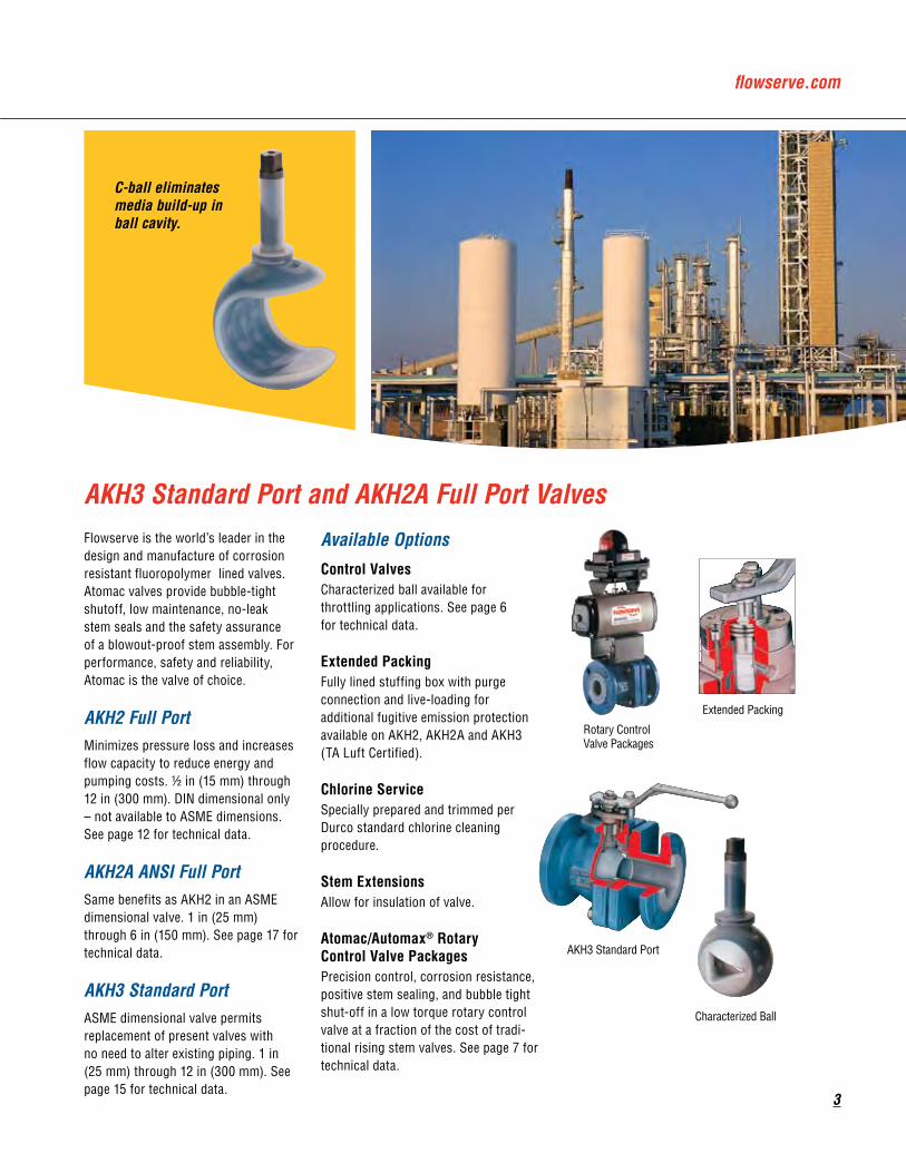
flowserve.com
3
AKH3 Standard Port and AKH�A Full Port ValvesFlowserve is the world’s leader in the design and manufacture of corrosion resistant fluoropolymer lined valves. Atomac valves provide bubble-tight shutoff, low maintenance, no-leak stem seals and the safety assurance of a blowout-proof stem assembly. For performance, safety and reliability, Atomac is the valve of choice.
AKH� Full PortMinimizes pressure loss and increases flow capacity to reduce energy and pumping costs. 1⁄2 in (15 mm) through 12 in (300 mm). DIN dimensional only – not available to ASME dimensions. See page 12 for technical data.
AKH�A ANSI Full PortSame benefits as AKH2 in an ASME dimensional valve. 1 in (25 mm) through 6 in (150 mm). See page 17 for technical data.
AKH3 Standard PortASME dimensional valve permits replacement of present valves with no need to alter existing piping. 1 in (25 mm) through 12 in (300 mm). See page 15 for technical data.
Available Options
Control ValvesCharacterized ball available for throttling applications. See page 6 for technical data.
Extended PackingFully lined stuffing box with purge connection and live-loading for additional fugitive emission protection available on AKH2, AKH2A and AKH3 (TA Luft Certified).
Chlorine ServiceSpecially prepared and trimmed per Durco standard chlorine cleaning procedure.
Stem ExtensionsAllow for insulation of valve.
Atomac/Automax® Rotary Control Valve PackagesPrecision control, corrosion resistance, positive stem sealing, and bubble tight shut-off in a low torque rotary control valve at a fraction of the cost of tradi-tional rising stem valves. See page 7 for technical data.
C-ball eliminates media build-up inball cavity.
Extended Packing
AKH3 Standard Port
Characterized Ball
Rotary Control Valve Packages
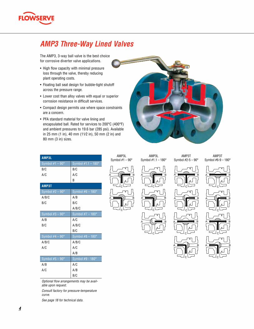
�
The AMP3, 3-way ball valve is the best choice for corrosive diverter valve applications.
• High flow capacity with minimal pressure loss through the valve, thereby reducing plant operating costs.
• Floating ball seat design for bubble-tight shutoff across the pressure range.
• Lower cost than alloy valves with equal or superior corrosion resistance in difficult services.
• Compact design permits use where space constraints are a concern.
• PFA standard material for valve lining and encapsulated ball. Rated for services to 200°C (400°F) and ambient pressures to 19.6 bar (285 psi). Available in 25 mm (1 in), 40 mm (11⁄2 in), 50 mm (2 in) and 80 mm (3 in) sizes.
AMP3 Three-Way Lined Valves
AMP3L
Symbol #1 – 90° Symbol #1.1 – 180°
B/C
A/C
B/C
A/C
B
AMP3T
Symbol #2 – 90° Symbol #6 – 180°
A/B/C
B/C
A/B
B/C
A/B/C
Symbol #3 – 90° Symbol #7 – 180°
A/B
B/C
A/C
A/B/C
B/C
Symbol #4 – 90° Symbol #8 – 180°
A/B/C
A/C
A/B/C
A/C
A/B
Symbol #5 – 90° Symbol #9 - 180°
A/B
A/C
A/C
A/B
B/C
Optional flow arrangements may be avail-able upon request.
Consult factory for pressure-temperature curve.
See page 18 for technical data.
A B
C
A B
C
A B
C
A B
C
A B
C
A B
C
A B
C
A B
C
A B
C
A B
C
A B
C
A B
C
A B
C
AMP 3L symbolNr.1-90ϒ
AMP 3L symbolNr.1.1-180ϒ
AMP 3T symbolNr.2/5-90ϒ
AMP 3T symbolNr.6/9-180ϒ
AMP3LSymbol #1 – 90°
AMP3LSymbol #1.1 – 180°
AMP3TSymbol #2-5 – 90°
AMP3TSymbol #6-9 – 180°

flowserve.com
�
AKH� Ceramic Lined ValvesRecommended when nothing else will work in abrasive slurries, high temperature corrosives and services with large temperature fluctuations. Available in 25 mm (1 in), 40 mm (11⁄2 in), 50 mm (2 in), 80 mm (3 in) and 100 mm (4 in) sizes.
Minimum cavity space minimizes the retention of line media within the body cavity so product contamination problems are significantly reduced.
Optional V-port ball provides equal percentage control for throttling abrasive/corrosive media.
For complete information, request Bulletin VA-50.
See pages 22 and 23 for technical data.
All interior body surfaces and the ball are made of solid Mg-PSZ for superior erosion/corrosion resistance. Excellent strength and thermal shock resistance.
Ball seals against machined seat areas for shutoff to ANSI B16.104 Class IV, or DIN 3230, part 3, BN leakrate 3.
Full port minimizes pressure loss and increases flow capacity to reduce energy and pumping costs.
Stem sealing requires virtually no maintenance and provides low stem torque. Adjuster and packing gland feature a ball and socket fit for certain and even stem sealing reliability.
ISO 5211 mounting pad makes actuator mounting quick and easy.
A wide selection of stem material options available … 316 stainless steel, Hastelloy® C-276 or Mg-PSZ (Partially Stabilized Zirconia) ceramic.
PTFE chevron or graphite packing rings in the deep stuffing box protects against external leakage to the atmosphere.

�
V-Port Control ValvesIn addition to the features and benefits that have made it the process industry’s most preferred lined ball valve worldwide, Atomac offers the V-port ball valve for precise modulating control services. Atomac V-port valves are avail-able in 1 in (25 mm), 11⁄2 in (40 mm), 2 in (50 mm), 3 in (80 mm) and 4 in (100 mm) sizes and in models AKH3, AKH2A, AKH2.
Maximum CV (KV) Values for V-Port AKH3 Valves
in (mm) CV KV
1 (25) 6 ⁄14 5⁄12
11⁄2 (40) 15 13
2 (50) 40 36
3 (80) 65 56
4 (100) 141 122
6 (150) 189 163
00
10
20
30
40
50
60
70
80
90
100
10 20 30 40 50
% of Opening – Live Zero
% o
f Max
imum
CV
60 70 80 90 100
A Typical Characteristic Curve for V-Port AKH3 Valves
CV = US gal/min at 1 psi ∆ p (KV = m3/hr at 1 bar ∆ p)
Refer to Sections II and IV of the Durco Technical Manual for valve and actuator sizing.
Consult factory for AKH2A data.
ISO 5211 mounting pad facilitates actuation.
flowserve.com
To find your local Flowserve representative:
For more information about Flowserve Corporation, visit www.flowserve.com or call USA 1 800 225 6989
Flowserve Corporation has established industry leadership in the design and manufacture of its products. When properly selected, this Flowserve product is designed to perform its intended function safely during its useful life. However, the purchaser or user of Flowserve products should be aware that Flowserve products might be used in numerous applications under a wide variety of industrial service conditions. Although Flowserve can (and often does) provide general guidelines, it cannot provide specific data and warnings for all possible applications. The purchaseruser must therefore assume the ultimate responsibility for the proper sizing and selection, installation, operation, and maintenance of Flowserve products. The purchaser/user should read and understand the Installation Operation Maintenance (IOM) instructions included with the product, and train its employees and contractors in the safe use of Flowserve products in connection with the specific application.
While the information and specifications contained in this literature are believed to be accurate, they are supplied for informative purposes only and should not be considered certified or as a guarantee of satisfactory results by reliance thereon. Nothing contained herein is to be construed as a warranty or guarantee, express or implied, regarding any matter with respect to this product. Because Flowserve is continually improving and upgrading its product design, the specifications, dimensions and information contained herein are subject to change without notice. Should any question arise concerning these provisions, the purchaser/user should contact Flowserve Corporation at any one of its worldwide operations or offices.
© 2005 Flowserve Corporation, Irving, Texas, USA. Flowserve is a registered trademark of Flowserve Corporation.
United StatesFlowserve CorporationFlow Control Division 1978 Foreman DriveCookeville, Tennessee 38501Phone: 931 432 4021Fax: 931 432 3105
EuropeFlowserve Ahaus GmbHVon Braun Strasse 19aD-48683 AhausGermanyPhone: + 49.2561.686.0Fax: + 49.2561.68639
Asia PacificFlowserve Pte. Ltd.12 Tuas Avenue 20Republic of Singapore 638824Phone: 65 862 3332Fax: 65 862 2800FCD ATENTB0010-00 (Part VA-10) Printed in USA.

Series 41Technical Drawing FL41-001
Date: April 30, 2009
Size 2 2.5 3 4 5 6 8 10 12L 7.02 7.48 7.99 9.02 10 10.51 11.5 12.99 14.02d 2.01 2.52 2.99 4.02 5 5.98 7.99 10 12.01D 5.98 7.01 7.48 9.02 10 10.98 13.5 15.98 19.02C 4.74 5.49 6 7.5 8.5 9.51 11.75 14.25 17.01P 3.62 4.13 5 6.18 7.32 8.5 10.63 12.76 15b 0.63 0.71 0.75 0.94 0.94 1.02 1.14 1.22 1.26H 15.39 16.06 17.99 21.18 24.02 27.28 33.98 40.79 44.49W 7.87 7.87 9.84 11.02 11.02 11.81 13.78 15.75 17.72
n-Ød 4-.75 4-.75 4-.75 8-.75 8-.87 8-.87 8-.87 12-.98 12-.98
VALVE SIZE FLANGE DRILLING
PRESSURE RATING
CUSTOMER/PROJECT
INQ/PO NO.
ORDER NO.
CERTIFIED BY DATE
DIMENSIONAL DATA SHEET
NON-RISING STEM GATE VALVE
SERIES 41
SIZES 2”-12”
PART NO.
DRAWING NO.
DATE
REV
FL41-001
4/30/09
A
Flow Line Valve and Controls, Inc.PO Box 677, 110 Main Project Rd • Schriever, LA 70395 • Phone (985) 414-6004 • Fax (985) 414-6072
www.flowlinevalves.com
1 Body A216WBC2 Seat A105+13Cr3 StemNuts A182F6a4 Disc A216WCB+13Cr5 Stem-Nuts C952006 Cap A216WCB7 Washer 304SS8 Bolts A193B79 Nuts A19421110 Washer 304SS
11 Nuts A193B712 Packing 304SS13 Gland A126WCB14 PackingGland A27641015 PackingGland A216WCB16 Bolts A193B717 Nuts A19421118 Wheel A19719 Washer AISI103520 Nuts A194211
Components / Materials
Testing API 598
Components/Materials1 Body A216 WCB
2 Seat A105 + 13Cr Flange ANSI B16.53 Stem-Nuts A182 F6a Face to Face ANSI B16.104 Disc A216WCB+13Cr Test to API 5985 Stem-Nuts C95200 Marking MSS-SP-256 Cap A216WCB
7 Washer 304SS
8 Bolts A193 B7 Testing API 5989 Nuts A194 211 Shell Hydro 450psi10 Washer 304SS Seat Air 80psi11 Nuts A193 B7 Back Seat Hydro 315psi12 Packing 304SS
13 Gland A126 WCB
14 Packing Gland A276 410
15 Packing Gland A216 WCB
16 Bolts A193 B7
17 Nuts A194 211
18 Wheel A197
19 Washer AISI 1035
20 Nuts A194 211
Pressure / Temperature RatingsPressure / Temperature RatingsTemp °F WCB Temp °F WCB
-20 to 100 285 700 110200 260 750 95300 230 800 80400 200 850 65500 170 900 50600 140 950 35650 125 1000 20
FacetoFace ANSIB16.10FlangeDimension ANSIB16.5Test API598Pressure ANSIB16.34Marking MSS-SP-25
Size Weight/lb
2" 382.5" 583" 664" 975" 1216" 1598" 24210" 39212" 594
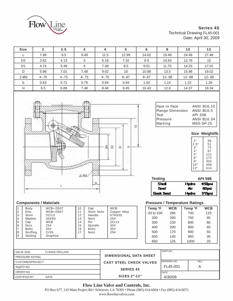
Series 45Technical Drawing FL45-001
Date: April 30, 2009
Size 2 2.5 3 4 5 6 8 10 12L 7.99 8.5 9.49 11.5 12.99 14.02 19.49 24.49 27.48
D2 3.62 4.13 5 6.18 7.32 8.5 10.63 12.76 15D1 4.74 5.49 6 7.48 8.5 9.51 11.75 14.25 17.01D 5.98 7.01 7.48 9.02 10 10.98 13.5 15.98 19.02
Z-Ød 4-.75 4-.75 4-.75 4-.75 8-.87 8-.87 12-.98 12-.98 12-.98b 0.63 0.71 0.75 0.94 0.94 1.02 1.14 1.22 1.26H 6.5 6.89 7.48 8.46 9.45 10.43 12.6 14.37 16.34
VALVE SIZE FLANGE DRILLING
PRESSURE RATING
CUSTOMER/PROJECT
INQ/PO NO.
ORDER NO.
CERTIFIED BY DATE
DIMENSIONAL DATA SHEET
CAST STEEL CHECK VALVES
SERIES 45
SIZES 2”-12”
PART NO.
DRAWING NO.
DATE
REV
FL45-001
4/30/09
A
Flow Line Valve and Controls, Inc.PO Box 677, 110 Main Project Rd • Schriever, LA 70395 • Phone (985) 414-6004 • Fax (985) 414-6072
www.flowlinevalves.com
1 Body WCB+D5072 Disc WCB+D5073 Stem 2Cr134 Washer 304SS5 Cap WCB6 Nuts 25#7 Bolts 35#8 Stuffing CrSS9 Sealing Graphite
10 Cap WCB11 StemNuts CopperAlloy12 Handle KTH33013 Nuts 25#14 Pin 2Cr1315 Spindle 35#16 Bolts 35#17 Nuts 25#
Components / Materials
FacetoFace ANSIB16.10FlangeDimension ANSIB16.5Test API598Pressure ANSIB16.34Marking MSS-SP-25
Testing API 598
Pressure / Temperature RatingsPressure / Temperature RatingsTemp °F WCB Temp °F WCB
-20 to 100 285 700 110200 260 750 95300 230 800 80400 200 850 65500 170 900 50600 140 950 35650 125 1000 20
Size Weight/lb
2" 382.5" 513" 734" 975" 1216" 1728" 30210" 45612" 614

ABC Ltd. Water Management System
Lagos Port, Nigeria
Technical Proposal‐ Water Management System Rev‐0 Page 24 of 27
Fire Fighting Equipments

extended coveragesprinklers general
care, installation, and maintenance guide
tecHnical data
August 19, 2011
the viking corporation, 210 n industrial park drive, Hastings mi 49058telephone: 269-945-9501 technical services: 877-384-5464 Fax: 269-818-1680 email: [email protected]
1. descriptionViking extended coverage sprinklers are thermosensitive spray sprinklers consisting of a small frame and either a glass bulb or a fusible operating element. Available styles include pendent, flush pendent, concealed pendent, concealed sidewall, upright, hori-zontal sidewall, flush horizontal sidewall, vertical sidewall, or conventional (old style). Extended coverage sprinklers are available with various finishes, temperature ratings, and K-Factors to meet design require-ments†. Equipped with a special deflector, the sprinklers are designed to meet density requirements for specific extended areas of coverage when the required minimum water supply is provided at the sprinkler. †Refer to the sprinkler technical data page for available styles, finishes, temperature ratings, and nominal K-Factors for specific sprinkler models.
2. listings and approvalsRefer to the Approval Charts on the appropriate sprinkler technical data page(s) and/or approval agency listings.
3. tecHnical dataSpecifications:Refer to the appropriate sprinkler technical data sheet.material standards:Refer to the appropriate sprinkler technical data sheet.
4. installationa. care and Handling (also refer to Bulletin - care and Handling of sprinklers, Form no. F_091699.)Sprinklers must be handled with care. They must be stored in a cool, dry place in their original shipping container. Never install
sprinklers that have been dropped, damaged, or exposed to temperatures exceeding the maximum ambient temperature al-lowed (refer to the temperature chart on the sprinkler technical data page). Never install any glass-bulb sprinkler if the bulb is cracked or if there is a loss of liquid from the bulb. A small air bubble should be present in the glass bulb. Any sprinkler with a loss of liquid from the glass bulb or damage to the fusible element should be destroyed immediately. (Note: Installing glass bulb sprinklers in direct sunlight (ultraviolet light) may affect the color of the dye used to color code the bulb. This color change does not affect the integrity of the bulb.)
Sprinklers must be protected from mechanical damage during storage, transport, handling, and after installation. Sprinklers subject to mechanical damage must be protected with an approved sprinkler guard.
Use only sprinklers listed as corrosion resistant when subject to corrosive environments. When installing corrosion-resistant sprin-klers, take care not to damage the corrosion-resistant coating. Use only the special wrench designed for installing coated or recessed Viking sprinklers (any other wrench may damage the unit).
concealed sprinklers must be installed in neutral or negative pressure plenums only! Use care when locating sprinklers near fixtures that can generate heat. Do not install sprinklers where they could be exposed to
temperatures exceeding the maximum recommended ambient temperature for the temperature rating used.Wet pipe systems must be provided with adequate heat. Sprinklers supplied from dry systems in areas subject to freezing must be
listed dry sprinklers, or upright or horizontal sidewall sprinklers installed so that water is not trapped. For dry systems, pendent sprinklers and sidewall sprinklers installed on return bends are permitted, where the sprinklers, return bend, and branch line piping are in an area maintained at or above 40 °F (4 °C).
B. installation instructionsViking sprinklers are manufactured and tested to meet the rigid requirements of approving agencies. They are designed to be installed in accordance with recognized installation standards. Deviation from the standards or any alteration to sprinklers or cover plate assemblies after they leave the factory including, but not limited to: painting, plating, coating, or modification, may render them inoperative and will automatically nullify the approvals and any guarantee made by The Viking Corporation.Before installation, be sure to have the appropriate sprinkler model and style, with the correct K-Factor, temperature rating, and response characteristics. Sprinklers must be installed after the piping is in place to prevent mechanical damage. Keep sprinklers with protective caps or bulb shields contained within the caps or shields during installation and testing, and any time the sprinkler is shipped or handled.
Form No. F_010400 Replaces page EC1-3, dated January 21, 2011. (Updated for sprinkler VK680.)
viking technical data may be found on the viking corporation’s Web site at
http://www.vikinggroupinc.com.the Web site may include a more recent
edition of this technical data page.
Sprinkler EC1
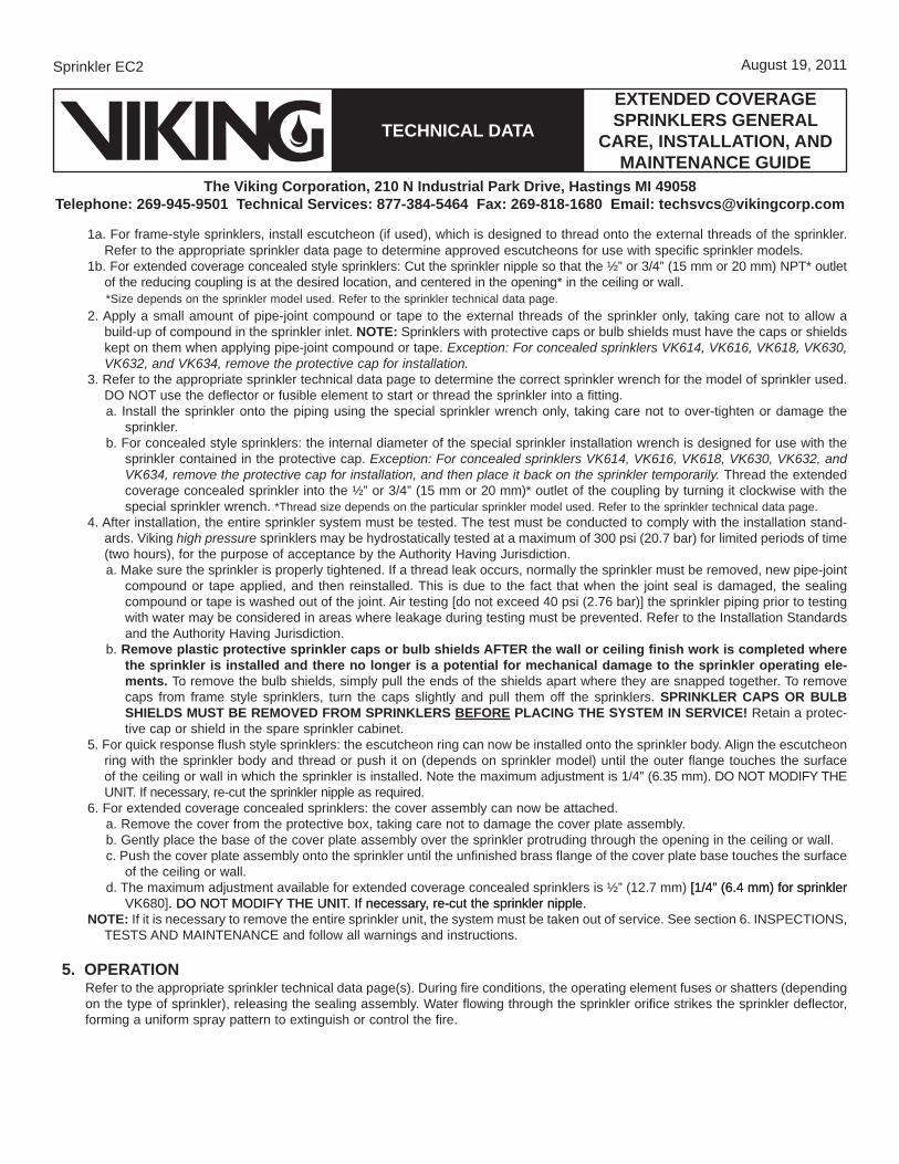
tecHnical data
August 19, 2011
the viking corporation, 210 n industrial park drive, Hastings mi 49058telephone: 269-945-9501 technical services: 877-384-5464 Fax: 269-818-1680 email: [email protected]
extended coveragesprinklers general
care, installation, and maintenance guide
1a. For frame-style sprinklers, install escutcheon (if used), which is designed to thread onto the external threads of the sprinkler. Refer to the appropriate sprinkler data page to determine approved escutcheons for use with specific sprinkler models.
1b. For extended coverage concealed style sprinklers: Cut the sprinkler nipple so that the ½” or 3/4” (15 mm or 20 mm) NPT* outlet of the reducing coupling is at the desired location, and centered in the opening* in the ceiling or wall.
*Size depends on the sprinkler model used. Refer to the sprinkler technical data page.2. Apply a small amount of pipe-joint compound or tape to the external threads of the sprinkler only, taking care not to allow a
build-up of compound in the sprinkler inlet. note: Sprinklers with protective caps or bulb shields must have the caps or shields kept on them when applying pipe-joint compound or tape. Exception: For concealed sprinklers VK614, VK616, VK618, VK630, VK632, and VK634, remove the protective cap for installation.
3. Refer to the appropriate sprinkler technical data page to determine the correct sprinkler wrench for the model of sprinkler used. DO NOT use the deflector or fusible element to start or thread the sprinkler into a fitting. a. Install the sprinkler onto the piping using the special sprinkler wrench only, taking care not to over-tighten or damage the
sprinkler.b. For concealed style sprinklers: the internal diameter of the special sprinkler installation wrench is designed for use with the
sprinkler contained in the protective cap. Exception: For concealed sprinklers VK614, VK616, VK618, VK630, VK632, and VK634, remove the protective cap for installation, and then place it back on the sprinkler temporarily. Thread the extended coverage concealed sprinkler into the ½” or 3/4” (15 mm or 20 mm)* outlet of the coupling by turning it clockwise with the special sprinkler wrench. *Thread size depends on the particular sprinkler model used. Refer to the sprinkler technical data page.
4. After installation, the entire sprinkler system must be tested. The test must be conducted to comply with the installation stand-ards. Viking high pressure sprinklers may be hydrostatically tested at a maximum of 300 psi (20.7 bar) for limited periods of time (two hours), for the purpose of acceptance by the Authority Having Jurisdiction.a. Make sure the sprinkler is properly tightened. If a thread leak occurs, normally the sprinkler must be removed, new pipe-joint
compound or tape applied, and then reinstalled. This is due to the fact that when the joint seal is damaged, the sealing compound or tape is washed out of the joint. Air testing [do not exceed 40 psi (2.76 bar)] the sprinkler piping prior to testing with water may be considered in areas where leakage during testing must be prevented. Refer to the Installation Standards and the Authority Having Jurisdiction.
b. remove plastic protective sprinkler caps or bulb shields aFter the wall or ceiling finish work is completed where the sprinkler is installed and there no longer is a potential for mechanical damage to the sprinkler operating ele-ments. To remove the bulb shields, simply pull the ends of the shields apart where they are snapped together. To remove caps from frame style sprinklers, turn the caps slightly and pull them off the sprinklers. sprinkler caps or BulB sHields must Be removed From sprinklers BeFore placing tHe sYstem in service! Retain a protec-tive cap or shield in the spare sprinkler cabinet.
5. For quick response flush style sprinklers: the escutcheon ring can now be installed onto the sprinkler body. Align the escutcheon ring with the sprinkler body and thread or push it on (depends on sprinkler model) until the outer flange touches the surface of the ceiling or wall in which the sprinkler is installed. Note the maximum adjustment is 1/4” (6.35 mm). DO NOT MODIFY THE UNIT. If necessary, re-cut the sprinkler nipple as required.
6. For extended coverage concealed sprinklers: the cover assembly can now be attached.a. Remove the cover from the protective box, taking care not to damage the cover plate assembly.b. Gently place the base of the cover plate assembly over the sprinkler protruding through the opening in the ceiling or wall.c. Push the cover plate assembly onto the sprinkler until the unfinished brass flange of the cover plate base touches the surface
of the ceiling or wall.d. The maximum adjustment available for extended coverage concealed sprinklers is ½” (12.7 mm) [1/4” (6.4 mm) for sprinkler[1/4” (6.4 mm) for sprinkler
VK680]. DO NOT MODIFY THE UNIT. If necessary, re-cut the sprinkler nipple.. DO NOT MODIFY THE UNIT. If necessary, re-cut the sprinkler nipple.note: If it is necessary to remove the entire sprinkler unit, the system must be taken out of service. See section 6. INSPECTIONS,
TESTS AND MAINTENANCE and follow all warnings and instructions.
5. operationRefer to the appropriate sprinkler technical data page(s). During fire conditions, the operating element fuses or shatters (depending on the type of sprinkler), releasing the sealing assembly. Water flowing through the sprinkler orifice strikes the sprinkler deflector, forming a uniform spray pattern to extinguish or control the fire.
Sprinkler EC2
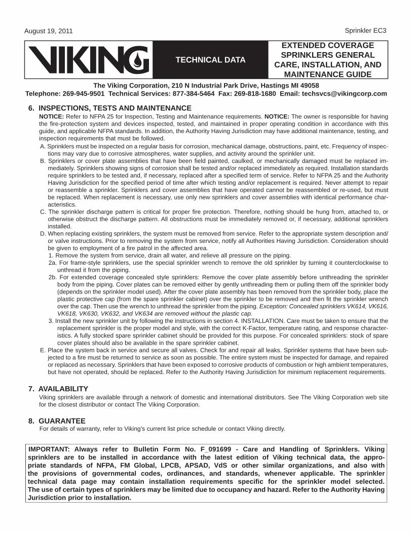
extended coveragesprinklers general
care, installation, and maintenance guide
tecHnical data
August 19, 2011
the viking corporation, 210 n industrial park drive, Hastings mi 49058telephone: 269-945-9501 technical services: 877-384-5464 Fax: 269-818-1680 email: [email protected]
6. inspections, tests and maintenancenotice: Refer to NFPA 25 for Inspection, Testing and Maintenance requirements. notice: The owner is responsible for having the fire-protection system and devices inspected, tested, and maintained in proper operating condition in accordance with this guide, and applicable NFPA standards. In addition, the Authority Having Jurisdiction may have additional maintenance, testing, and inspection requirements that must be followed.A. Sprinklers must be inspected on a regular basis for corrosion, mechanical damage, obstructions, paint, etc. Frequency of inspec-
tions may vary due to corrosive atmospheres, water supplies, and activity around the sprinkler unit.B. Sprinklers or cover plate assemblies that have been field painted, caulked, or mechanically damaged must be replaced im-
mediately. Sprinklers showing signs of corrosion shall be tested and/or replaced immediately as required. Installation standards require sprinklers to be tested and, if necessary, replaced after a specified term of service. Refer to NFPA 25 and the Authority Having Jurisdiction for the specified period of time after which testing and/or replacement is required. Never attempt to repair or reassemble a sprinkler. Sprinklers and cover assemblies that have operated cannot be reassembled or re-used, but must be replaced. When replacement is necessary, use only new sprinklers and cover assemblies with identical performance char-acteristics.
C. The sprinkler discharge pattern is critical for proper fire protection. Therefore, nothing should be hung from, attached to, or otherwise obstruct the discharge pattern. All obstructions must be immediately removed or, if necessary, additional sprinklers installed.
D. When replacing existing sprinklers, the system must be removed from service. Refer to the appropriate system description and/or valve instructions. Prior to removing the system from service, notify all Authorities Having Jurisdiction. Consideration should be given to employment of a fire patrol in the affected area.1. Remove the system from service, drain all water, and relieve all pressure on the piping.2a. For frame-style sprinklers, use the special sprinkler wrench to remove the old sprinkler by turning it counterclockwise to
unthread it from the piping.2b. For extended coverage concealed style sprinklers: Remove the cover plate assembly before unthreading the sprinkler
body from the piping. Cover plates can be removed either by gently unthreading them or pulling them off the sprinkler body (depends on the sprinkler model used). After the cover plate assembly has been removed from the sprinkler body, place the plastic protective cap (from the spare sprinkler cabinet) over the sprinkler to be removed and then fit the sprinkler wrench over the cap. Then use the wrench to unthread the sprinkler from the piping. Exception: Concealed sprinklers VK614, VK616, VK618, VK630, VK632, and VK634 are removed without the plastic cap.
3. Install the new sprinkler unit by following the instructions in section 4. INSTALLATION. Care must be taken to ensure that the replacement sprinkler is the proper model and style, with the correct K-Factor, temperature rating, and response character-istics. A fully stocked spare sprinkler cabinet should be provided for this purpose. For concealed sprinklers: stock of spare cover plates should also be available in the spare sprinkler cabinet.
E. Place the system back in service and secure all valves. Check for and repair all leaks. Sprinkler systems that have been sub-jected to a fire must be returned to service as soon as possible. The entire system must be inspected for damage, and repaired or replaced as necessary. Sprinklers that have been exposed to corrosive products of combustion or high ambient temperatures, but have not operated, should be replaced. Refer to the Authority Having Jurisdiction for minimum replacement requirements.
7. availaBilitYViking sprinklers are available through a network of domestic and international distributors. See The Viking Corporation web site for the closest distributor or contact The Viking Corporation.
8. guaranteeFor details of warranty, refer to Viking’s current list price schedule or contact Viking directly.
Sprinkler EC3
important: always refer to Bulletin Form no. F_091699 - care and Handling of sprinklers. viking sprinklers are to be installed in accordance with the latest edition of viking technical data, the appro-priate standards of nFpa, Fm global, lpcB, apsad, vds or other similar organizations, and also with the provisions of governmental codes, ordinances, and standards, whenever applicable. the sprinkler technical data page may contain installation requirements specific for the sprinkler model selected. the use of certain types of sprinklers may be limited due to occupancy and hazard. refer to the authority Having Jurisdiction prior to installation.
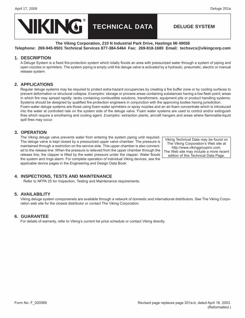
TECHNICAL DATA
April 17, 2009
DELUGE SYSTEM
The Viking Corporation, 210 N Industrial Park Drive, Hastings MI 49058Telephone: 269-945-9501 Technical Services 877-384-5464 Fax: 269-818-1680 Email: [email protected]
Deluge 201a
1. DESCRIPTIONA Deluge System is a fixed fire-protection system which totally floods an area with pressurized water through a system of piping and open nozzles or sprinklers. The system piping is empty until the deluge valve is activated by a hydraulic, pneumatic, electric or manual release system.
2. APPLICATIONSRegular deluge systems may be required to protect extra-hazard occupancies by creating a fire buffer zone or by cooling surfaces to prevent deformation or structural collapse. Examples: storage or process areas containing substances having a low flash point; areas in which fire may spread rapidly; tanks containing combustible solutions, transformers, equipment pits or product handling systems. Systems should be designed by qualified fire-protection engineers in conjunction with the approving bodies having jurisdiction.Foam-water deluge systems are those using foam-water sprinklers or spray nozzles and an air-foam concentrate which is introduced into the water at controlled rate on the system side of the deluge valve. Foam water systems are used to control and/or extinguish fires which require a smothering and cooling agent. Examples: extraction plants, aircraft hangars and areas where flammable-liquid spill fires may occur.
3. OPERATIONThe Viking deluge valve prevents water from entering the system piping until required. The deluge valve is kept closed by a pressurized upper valve chamber. The pressure is maintained through a restriction on the service side. This upper chamber is also connect-ed to the release line. When the pressure is relieved from the upper chamber through the release line, the clapper is lifted by the water pressure under the clapper. Water floods the system and rings alarm. For complete operation of individual Viking devices, see the applicable device pages in the Engineering and Design Data Book.
4. INSPECTIONS, TESTS AND MAINTENANCERefer to NFPA 25 for Inspection, Testing and Maintenance requirements.
5. AVAILAbILITYViking deluge system componenets are available through a network of domestic and international distributors. See The Viking Corpo-ration web site for the closest distributor or contact The Viking Corporation.
6. GUARANTEEFor details of warranty, refer to Viking’s current list price schedule or contact Viking directly.
Revised page replaces page 201a-b, dated April 18, 2003. (Reformatted.)
Form No. F_020589
Viking Technical Data may be found on The Viking Corporation’s Web site at
http://www.vikinggroupinc.com.The Web site may include a more recent
edition of this Technical Data Page.
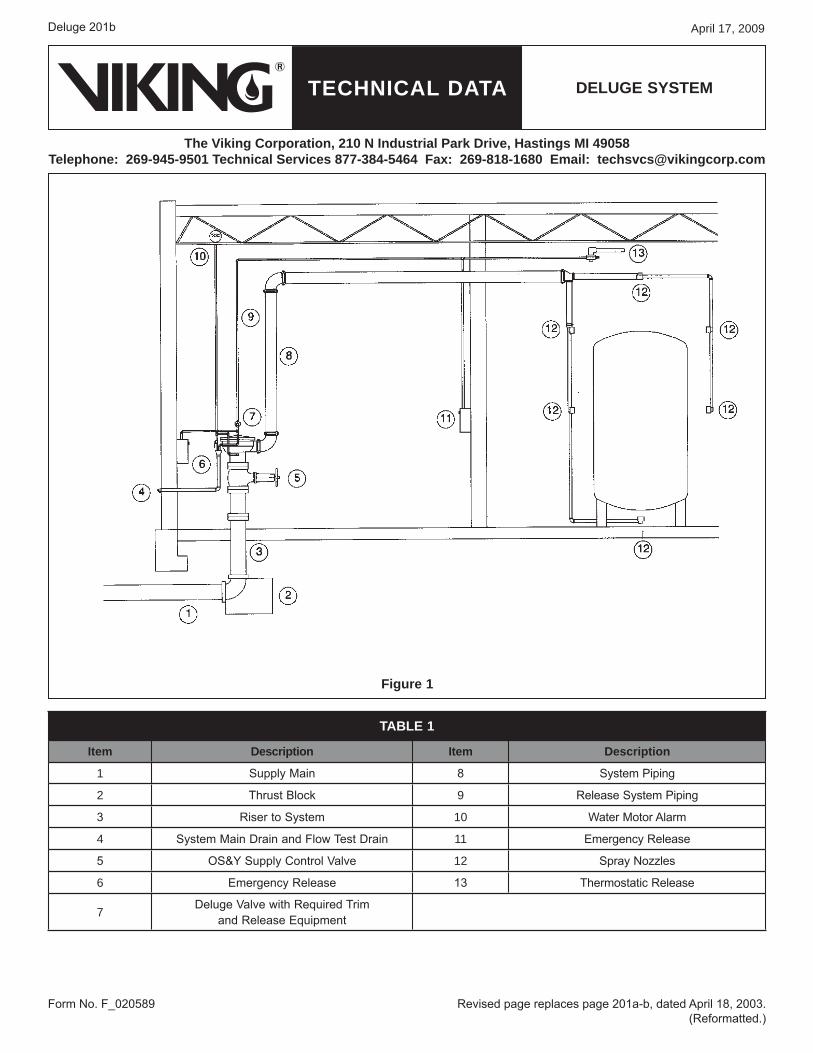
TECHNICAL DATA
April 17, 2009
DELUGE SYSTEM
The Viking Corporation, 210 N Industrial Park Drive, Hastings MI 49058Telephone: 269-945-9501 Technical Services 877-384-5464 Fax: 269-818-1680 Email: [email protected]
Deluge 201b
Form No. F_020589 Revised page replaces page 201a-b, dated April 18, 2003. (Reformatted.)
TAbLE 1
Item Description Item Description
1 Supply Main 8 System Piping
2 Thrust Block 9 Release System Piping
3 Riser to System 10 Water Motor Alarm
4 System Main Drain and Flow Test Drain 11 Emergency Release
5 OS&Y Supply Control Valve 12 Spray Nozzles
6 Emergency Release 13 Thermostatic Release
7 Deluge Valve with Required Trim and Release Equipment
Figure 1

ADVANCED DETECTION

NOTIFIER’s ONYX Series intelligent fire alarm systems respond rapidly to incipient fire signatures with unmatched precision. At thesame time, they significantly reduce the occurrence of nuisance alarms. It’s all made possible by NOTIFIER’s ONYX AdvancedDetection technology, which maximizes speed, stability, and reliability. ONYX Advanced Detection is comprised of two key elements:a set of complex software algorithms found in all ONYX Series fire alarm panels and a suite of advanced, specialty detectors. Whenused together, these elements extend ONYX Intelligent Sensing capabilities far beyond that of typical spot-type smoke or gas detec-tion. From mission-critical applications where even a trace amount of undetected smoke is unacceptable, to environments wherethe presence of dust, moisture, or theater smoke is the norm, ONYX Intelligent Sensing is the answer.
IntelliQuadTM PLUS – Combination Smoke and Carbon Monoxide (CO) DetectorNOTIFIER’s IntelliQuad PLUS detector is a plug-in, addressable device that provides both fire and Carbon Monoxide (CO) detection. For fire, the detectorcombines four separate sensing elements in one unit (smoke, CO, infrared,and heat) to sense multiple components of a fire. This approach has enhancedsensitivity to real fire with heightened immunity to nuisance particulate. For CO, the detector’s electrochemical sensing cell creates a separate signalfor life safety CO detection. When used together with our addressable sounderbase you can replace as many as four separate devices for a cleaner and moreefficient installation.
SPEED, STABILITY, & RELIABILITY
N E W !

ONYX Advanced Detection offers nine levels of detector pre-alarm and alarm sensitivity settings. This allows users to opti-mize each detector’s sensitivity specifically to its individualenvironment. Sensitivity levels are programmable to alternateautomatically between day and night as occupancy changes.
HIGH SENSITIVITY
FOR EARLY WARNING
VIEWTM Laser Detector – Super Sensitive Spot-type Detection
The VIEW laser smoke sensor is programmable to be up to 100 times more sensitive thanstandard photoelectric smoke detection technology. VIEW is ideal for critical applicationswhere even a trace of undetected smoke is unacceptable or where high air flows canmake traditional smoke detectors ineffective.
Customize Detector Sensitivity tothe Environment, Day and Night
NOTIFIER’s Cooperative Sensing Technology evaluates sensor readings from up to three adjacent smoke sensors to verify uniformsmoke spread, a strong indication of a true fire condition. Based on the sensor data, the panel can quickly determine the differencebetween a real fire emergency and a nuisance condition.
Cooperative Sensing Analyzes Readings from Multiple Devices
AcclimateTM – Self-optimizes, Senses Heat and Smoke
The Acclimate Plus detector combines thermal and photoelectric tech-nologies into a single device. It constantly monitors ambient heat and par-ticulate conditions, adjusting sensitivity parameters and alarm thresholdsautomatically to maximize detection across a broad range of fire types.
MINIMIZE NUISANCE ALARMS
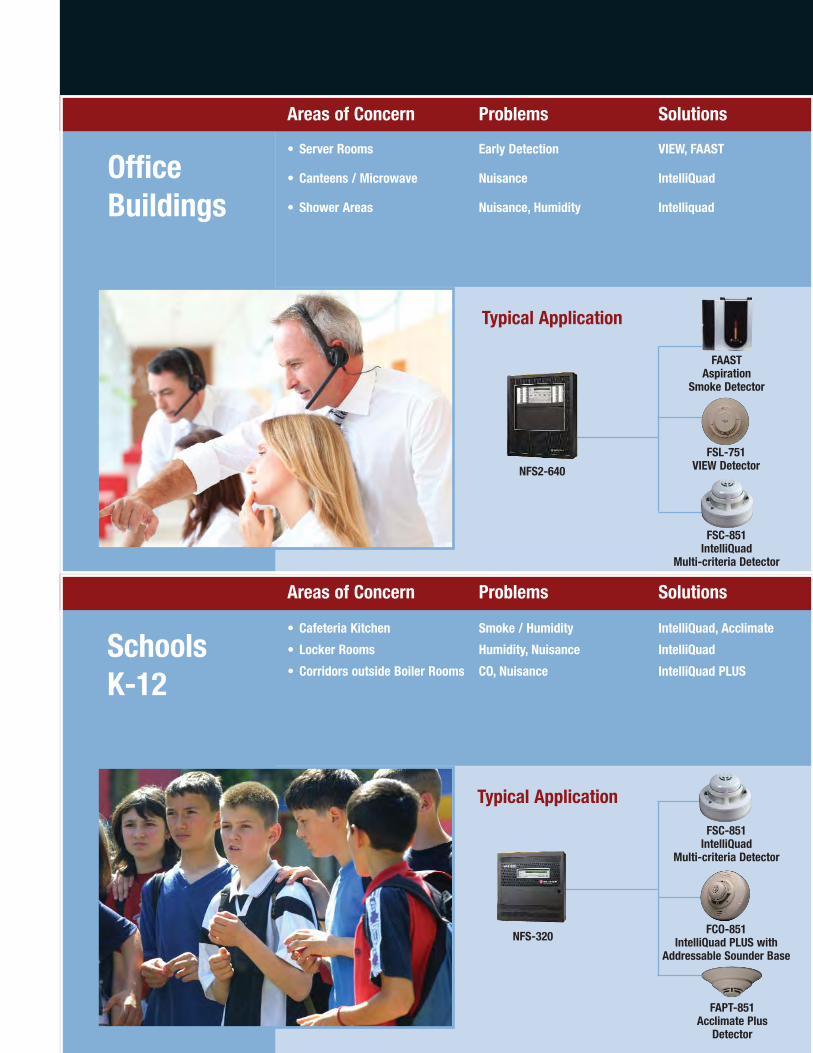
SchoolsK-12
OfficeBuildings
NFS2-640
FAASTAspiration
Smoke Detector
FSC-851IntelliQuad
Multi-criteria Detector
Typical Application
Typical Application
Areas of Concern Problems Solutions
• Server Rooms Early Detection VIEW, FAAST
• Canteens / Microwave Nuisance IntelliQuad
• Shower Areas Nuisance, Humidity Intelliquad
FSL-751VIEW Detector
FAPT-851Acclimate Plus
Detector
NFS-320
FSC-851IntelliQuad
Multi-criteria Detector
FCO-851IntelliQuad PLUS with
Addressable Sounder Base
Areas of Concern Problems Solutions
• Cafeteria Kitchen Smoke / Humidity IntelliQuad, Acclimate
• Locker Rooms Humidity, Nuisance IntelliQuad
• Corridors outside Boiler Rooms CO, Nuisance IntelliQuad PLUS

Hospitals andNursing Homes
COMMON HAZARDS AND SOLUTIONS
Colleges andUniversities
NFS2-640
Typical Application
Typical Application
FSC-851IntelliQuad
Multi-criteria Detector
NFS2-3030
FAASTAspiration
Smoke Detector
FCO-851IntelliQuad PLUS with
Addressable Sounder Base
FSL-751VIEW Detector
FCO-851IntelliQuad PLUS with
Addressable Sounder Base
FAASTAspiration Smoke Detector
Areas of Concern Problems Solutions
• Operating Rooms Very Early Warning VIEW, FAAST
• Patient Rooms Very Early Warning, IntelliQuad PLUSMulti-Criteria, CO Detection
• Server Rooms Very Early Warning VIEW, FAAST
Areas of Concern Problems Solutions
• Dormitories Smoking, CO Detection IntelliQuad PLUS
• Kitchens Nuisance IntelliQuad
• Telecommunications / Servers Very Early Detection VIEW, FAAST
• Science Labs Nuisance IntelliQuad
• Swimming Pools Humidity IntelliQuad

Hotels and Motels
Retail
NFS2-640
Typical Application
Typical Application
FSC-851IntelliQuad
Multi-criteria Detector
FSL-751VIEW Detector
FCO-851IntelliQuad PLUS with
Addressable Sounder Base
NFS-320
FAASTAspiration
Smoke Detector
FSC-851IntelliQuad
Multi-criteria Detector
Areas of Concern Problems Solutions
• Sleeping Rooms Smoking, CO Detection IntelliQuad PLUS
• Kitchens Nuisance IntelliQuad
• Rest Rooms Nuisance IntelliQuad
• Server / Electrical Early Warning VIEW, FAAST
• Laundry Rooms Nuisance, Early Warning, IntelliQuad PLUSCO Detection
Areas of Concern Problems Solutions
• Stock Rooms Dust / Lint FAAST
• Shopping Floor Dust, Area of Coverage FAAST
• Server/Computer Rooms Nuisance, Early Detection VIEW, FAAST, IntelliQuad

Aspirating Smoke Detection – EarlyWarning in Challenging Environments
Aspirating Smoke Detection (ASD) solutions provide early warning of an impending fire hazard. ASD can buy time to investigate an alarm and initiate an appropriate response to prevent injury, property damage, or business disruption. With a wide sensitivity range and multi-level warnings,even minute levels of smoke can be detected before a fire has time to escalate.It is also possible to connect the unit to the building's Ethernet connection inorder to provide access and monitoring from anywhere in the world.
A WIDE RANGE OF SENSITIVITY
IntelliQuadTM – The Ultimate Multi-criteria DetectorIntelliQuad senses smoke particulates, carbon monoxide (CO), heat, andinfrared signatures simultaneously to determine the presence of a firecondition. Sensor readings are continually evaluated against one another,allowing the detector to operate normally with high immunity to nuisanceconditions, while quickly responding to true alarm events.

M-B-AD1 8/11
For over 60 years, NOTIFIER has been a leader in the fire alarm industry. Today, we arethe largest manufacturer of engineered fire alarm systems with over 400 distributorsworldwide, and regional support operations on every continent for the flexibility andoptions your business needs.
NOTIFIER - Leaders in Life. Safety. Technology.
NOTIFIER WORLD HEADQUARTERS12 Clintonville RoadNorthford, CT 06472United States of AmericaTel: 203-484-7161Fax: 203-484-7118www.notifier.com
For information on regional office locations throughout the world, please visit www.notifier.com.
Fire AlarmControl Panels
EmergencyCommunicationsSystems
Fire AlarmNetworks
Advanced Fire &Smoke Detection
Fire, Security,CCTV Integration
Gas Detection
Hose reels and cabinetsFire hose reels and cabinetsRiser and extinguisher cabinetsGeneral purpose hose reels and cabinetsWheeled hose reels
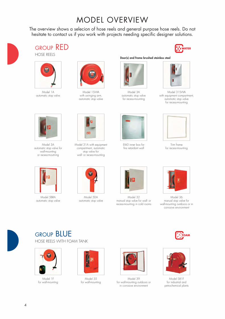
4
GROUP REDHOSE REELS
WATER
MODEL OVERVIEWThe overview shows a selecion of hose reels and general purpose hose reels. Do not hesitate to contact us if you work with projects needing specific designer solutions.
Model 1Aautomatic stop valve
Model 1SWAwith swinging arm,automatic stop valve
Model 3Aautomatic stop valve for recess-mounting
Model 31SWAwith equipment compartment,
automatic stop valve for recess-mounting
GROUP BLUEHOSE REELS WITH FOAM TANK
FOAM
Model 1Ffor wall-mounting
Model 35for wall-mounting
Model 39for wall-mounting outdoors or
in corrosive environment
Model S81Ffor industrial and
petrochemical plants
Model 3Aautomatic stop valve for
wall-mountingor recess-moutning
Door(s) and frame brushed stainless steel
Model 31A with equipment compartment, automatic
stop valve forwall- or recess-mounting
EI60 inner box for fire retardant wall
Trim framefor recess-mounting
Model 5BRA automatic stop valve
Model 5DAautomatic stop valve
Model 32manual stop valve for wall- or recess-mounting in cold rooms
Model 36manual stop valve for
wall-mounting outdoors or in corrosive environment

5
GROUP RED/GREENCOMBINED FIRE AND GENERAL PURPOSE HOSE REELS
WATER
Model S50L Model S56 Duo-L with extension hose
Model 100SWwith swinging arm, manual stop valve
Model 136cabinet for general purpose hose
reels model 100–110
GROUP GREENGENERAL PURPOSE HOSE REELS
WATER
Model 100 manual stop valve
Model 110SW with swinging arm for corrosive enviroment, manual stop valve
Model 120for hot water up to 80°C,
manual stop valve
Model 150for compressed air 8 bar
GROUP YELLOWFIRE EXTINGUISHERS
Model 3/EXT for wall- or recess-mounting
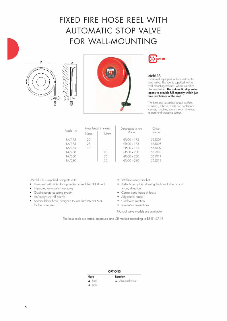
6
WATER
Model 1AHose reel equipped with an automatic stop valve. The reel is supplied with a wall-mounting bracket, which simplifies the installation. The automatic stop valveopens to provide full capacity within justtwo revolutions of the reel.
The hose reel is suitable for use in office buildings, schools, hotels and conference centres, hospitals, sports arenas, cinemas, airports and shopping centres.
FIXED FIRE HOSE REEL WITH AUTOMATIC STOP VALVEFOR WALL-MOUNTING
Model 1A is supplied complete with:• Hose reel with side discs powder coated RAL 3001 red • Integrated automatic stop valve• Quick-change coupling system• Jet/spray/shut-off nozzle• Special black hose, designed to standard BS EN 694
for fire hose reels
• Wall-mounting bracket• Roller hose guide allowing the hose to be run out
in any direction• Centre parts made of brass• Adjustable brake• Clockwise rotation• Installation instructions
Manual valve models are available
The hose reels are tested, approved and CE marked according to BS EN671-1
OPTIONS
Hose❏ Red❏ Light
Rotation❏ Anti-clockwise
1A/175 20 Ø600 x 175 5550071A/175 25 Ø600 x 175 5550081A/175 30 Ø600 x 175 5550091A/230 20 Ø600 x 230 5550101A/230 25 Ø600 x 230 5550111A/230 30 Ø600 x 230 555012
Model 1AHose length in metres
19mm 25mm
Dimensions in mmØ x A
Ordernumber
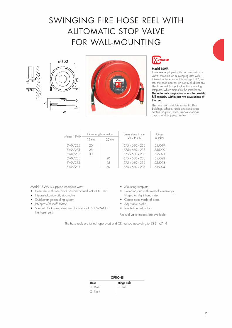
WATER
7
Model 1SWAHose reel equipped with an automatic stopvalve, mounted on a swinging arm with internal waterways which swings 180°, sothat the hose can be run out in all directions.The hose reel is supplied with a mountingtemplate, which simplifies the installation. The automatic stop valve opens to providefull capacity within just two revolutions ofthe reel.
The hose reel is suitable for use in office buildings, schools, hotels and conference centres, hospitals, sports arenas, cinemas, airports and shopping centres.
SWINGING FIRE HOSE REEL WITH AUTOMATIC STOP VALVEFOR WALL-MOUNTING
Model 1SWA is supplied complete with:• Hose reel with side discs powder coated RAL 3001 red • Integrated automatic stop valve• Quick-change coupling system• Jet/spray/shut-off nozzle• Special black hose, designed to standard BS EN694 for
fire hose reels
• Mounting template• Swinging arm with internal waterways,
hinged on right hand side• Centre parts made of brass• Adjustable brake• Installation instructions
Manual valve models are available
The hose reels are tested, approved and CE marked according to BS EN671-1
OPTIONS
Hose❏ Red❏ Light
Hinge side❏ Left
1SWA/235 20 675 x 630 x 235 5550191SWA/235 25 675 x 630 x 235 5550201SWA/235 30 675 x 630 x 235 5550211SWA/235 20 675 x 630 x 235 5550221SWA/235 25 675 x 630 x 235 5550231SWA/235 30 675 x 630 x 235 555024
Model 1SWAHose length in metres
19mm 25mm
Dimensions in mmW x H x D
Ordernumber

9
Model 3AThe hose reel, equipped with an automatic stop valve, is mounted on the door which opens180°. The reel can easily be removed from the cabinet during installation, so that one man alone can install the cabinet. The automaticstop valve opens to provide full capacitywithin just two revolutions of the reel.
The hose reel is suitable for use in office buildings, schools, hotels and conference centres, hospitals, sports arenas, cinemas, airports and shopping centres.
FIRE HOSE REEL WITH AUTOMATIC STOP VALVE AND CABINET FOR
WALL-MOUNTING OR RECESS-MOUNTING
3A/135 20 795 x 795 x 135 5550503A/135 25 795 x 795 x 135 5550513A/135 30 795 x 795 x 135 5550523A/200 20 795 x 795 x 200 5550533A/200 25 795 x 795 x 200 5550543A/200 30 795 x 795 x 200 5550553A/200 20 695 x 695 x 200 5550563A/200 25 695 x 695 x 200 5550573A/200 30 695 x 695 x 200 555058
Trim frame for recess-mounting 795 x 795 555204695 x 695 555203
The hose reels are tested, approved and CE marked according to BS EN671-1
Model 3AHose length in metres
19mm 25mm
Dimensions in mmW x H x D
Ordernumber
Model 3A is supplied complete with:• Hose reel with side discs powder coated RAL 3001 red• Integrated automatic stop valve• Quick-change coupling system• Jet/spray/shut-off nozzle• Special black hose, designed to standard
BS EN694 for hose reels• Special supply hose• Centre parts made of brass• Hinges on right hand side
• Adjustable brake• Door catch/release handle• Ø35mm knockouts for inlet pipework on 3 sides• Removable back wall, made of galvanized steel;
can be used as a mounting template• Cabinet, except back wall, powder coated
RAL 9010, white • Door sign in accordance with Council Directive
92/58/EEC• Installation instructions
Manual valve models are available
The same cabinet is used forwall-mounting and recess-mounting. The trim frame
for recess-mounting is ordered separately.
WATER
OPTIONS
Colour cabinet❏ RAL 3001 Red❏ RAL_(Smooth surface)
Door for manual call point❏ 90x90❏ 130x130
Hinge side❏ LeftTrim frame for recess-mounting ❏
Hose❏ Red❏ Light

11
Model 31AThe hose reel, equipped with an automatic stop valve, is mounted on the door which opens180°. The reel can easily be removed from thecabinet during fitting, which simplifies the install-ation. The cabinet is supplied with a separate equipment compartment for housing either fire extinguishers, a hydrant landing valve or otherequipment. The automatic stop valve opens to provide full capacity within just two revolutions of the reel.
Model 31A is suitable for use in office buildings, schools, hotels and conference centres, hospitals, sports arenas, cinemas, airports and shopping centres.
31A/230 20 695 x 1400 x 230 55531231A/230 25 695 x 1400 x 230 55531331A/230 30 695 x 1400 x 230 55531431A/285 20 695 x 1400 x 285 55531531A/285 25 695 x 1400 x 285 55531631A/285 30 695 x 1400 x 285 555317
Trim frame for recess-mounting 695 x 1400 555318
The hose reels are tested, approved and CE marked according to BS EN671-1
Model 31AHose length in metres
19mm 25mm
Dimensions in mmW x H x D
Ordernumber
Model 31A vertical combined cabinet is supplied complete with:• Hose reel with side discs powder coated RAL 3001 red• Integrated automatic stop valve• Quick-change coupling system• Spray/jet/shut-off nozzle• Special black hose, designed to standard BS EN694
for hose reels • Special supply hose• Centre parts made of brass• Adjustable brake
• Hinges on right hand side• Door catches/release handles• Ø35mm knockouts for inlet pipework on 3 sides• Removable back wall, made of galvanized steel; can be
used as a mounting template• Cabinet, except back wall, powder coated RAL 9010 white• Door sign in accordance with Council Directive 92/58/EEC• Installation instructions
Manual valve models are available
The same cabinet is used forwall-mounting and recess-mounting. The trim frame for
recess-mounting is ordered separately.
WATER
FIRE HOSE REEL WITH AUTOMATIC STOP VALVE AND VERTICAL COMBINED CABINET
WITH EQUIPMENT COMPARTMENT FOR WALL-MOUNTING OR RECESS-MOUNTING
OPTIONS
Colour cabinet❏ RAL 3001 Red❏ RAL_(Smooth surface)
Hose reel door for manualcall point❏ 90x90❏ 130x130
Hinge side❏ LeftTrim frame for recess-mounting ❏
Hose❏ Red❏ Light
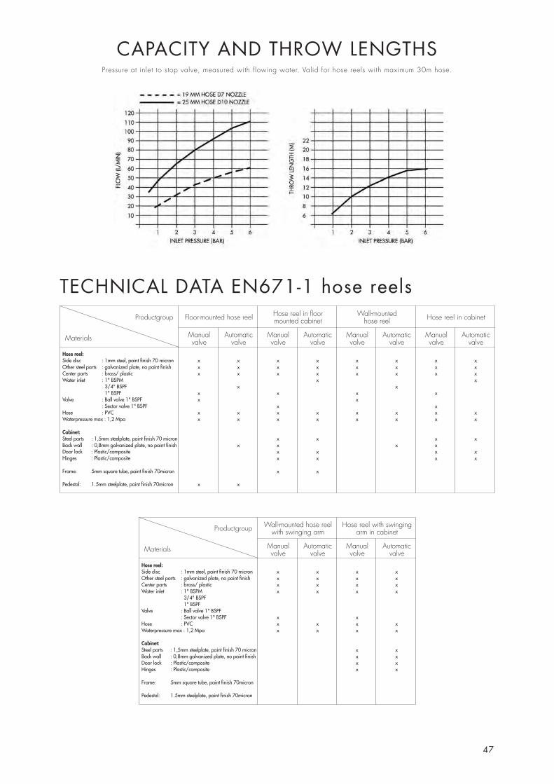
47
CAPACITY AND THROW LENGTHSPressure at inlet to stop valve, measured with flowing water. Valid for hose reels with maximum 30m hose.
Hose reel:Side disc : 1mm steel, paint finish 70 micronOther steel parts : galvanized plate, no paint finishCenter parts : brass/ plasticWater inlet : 1" BSPM
3/4" BSPF1" BSPF
Valve : Ball valve 1" BSPF: Sector valve 1" BSPF
Hose : PVCWaterpressure max : 1,2 Mpa
Cabinet:Steel parts : 1,5mm steelplate, paint finish 70 micronBack wall : 0,8mm galvanized plate, no paint finishDoor lock : Plastic/compositeHinges : Plastic/composite
Frame: 5mm square tube, paint finish 70micron
Pedestal: 1.5mm steelplate, paint finish 70micron
x x x x x x x xx x x x x x x xx x x x x x x x
x xx x
x x x xx x
x xx x x x x x x xx x x x x x x x
x x x xx x x x
x x x xx x x x
x x
x x
Hose reel:Side disc : 1mm steel, paint finish 70 micronOther steel parts : galvanized plate, no paint finishCenter parts : brass/ plasticWater inlet : 1" BSPM
3/4" BSPF1" BSPF
Valve : Ball valve 1" BSPF: Sector valve 1" BSPF
Hose : PVCWaterpressure max : 1,2 Mpa
Cabinet:Steel parts : 1,5mm steelplate, paint finish 70 micronBack wall : 0,8mm galvanized plate, no paint finishDoor lock : Plastic/compositeHinges : Plastic/composite
Frame: 5mm square tube, paint finish 70micron
Pedestal: 1.5mm steelplate, paint finish 70micron
x x x xx x x xx x x xx x x x
x xx x x xx x x x
x xx xx xx x
Manual Automaticvalve valve
Floor-mounted hose reel
Materials
Productgroup
Manual Automaticvalve valve
Hose reel in floor mounted cabinet
Manual Automaticvalve valve
Wall-mountedhose reel
Manual Automaticvalve valve
Hose reel in cabinet
Manual Automaticvalve valve
Wall-mounted hose reelwith swinging arm
Materials
Productgroup
Manual Automaticvalve valve
Hose reel with swingingarm in cabinet
TECHNICAL DATA EN671-1 hose reels
Kidde Products - Building Protection DivisionStation RoadHigh BenthamLancasterLA2 7NATel 01524 264000 Fax 01524 261580 e mail: [email protected]
THE WORLD’S LEADING MANUFACTURER OFHOSE REELS AND CABINETS
Kidde Products Ltd is a part of UTC Fire & Security, a division of the worldwide UnitedTechnologies Corporation, which includes Sikorsky Helicopters, Pratt & Whitney, OtisElevators and Carrier Air Conditioning.
Kidde Products has grown to become a major force in the worldwide safety business,with around 50 operating units in 20 countries and a 6,600-strong workforce.
The name Kidde came from Walter Kidde, the founding father of the US business. The name was adopted for the group because it was a brand name with a world widereputation.
Kidde group companies have been manufacturing hose reels since 1950. Kidde has builtup an unrivalled knowledge base in these products. A focus on the quality aspect and theability to introduce new ideas has made Kidde the preferred supplier of hose reels andcabinets all over Europe, the Middle East and the rest of the developed world. A modernfactory with the latest computer technology enables Kidde to make a range of productsto the appropriate European Standards in an environmentally friendly and quality con-scious environment. The combined efforts of highly qualified and experienced staff andoperatives give the Kidde product a unique quality that is well known and respectedworldwide.
The Kidde manufacturing facility is certified to ISO9001: 2000. All hose reels carry the CE mark confirming their compliance to the EU and many other standards.
Kidde hose reels are tested, approved, certified and CE-marked through an approved ac-creditation organization to EN671-1 for hose reels with semi-rigid hose.
WHAT ABOUT THE FUTURE?
Kidde has a programme of continuous development work to be able to serve you witheven better products. Regarding quality, there is no compromise. Kidde products will al-ways be at the forefront of design and performance giving a total cabability in anysituation.
GUARANTEE – SERVICE AND MAINTENANCE
Kidde offers a 5 year guarantee provided that the building owner or user fulfils the installation requirements and carries out documented annual service as specified in the Kidde service specifications and in EN671-3, the service part of the hose reel standard.
RO
CO
N 3033 07-04
Related Documents


