APOLLO LUNAR SAMPLE'RETURN CONTAINER - SUMMARY REPORT OAK RIDGE Y-12 PLANT OAK RIDGE, TENNESSEE prepared for the U.S. ATOMIC ENERGY COMMISSION under U.S. GOVERNMENT Contract W-7405 eng

Welcome message from author
This document is posted to help you gain knowledge. Please leave a comment to let me know what you think about it! Share it to your friends and learn new things together.
Transcript
APOLLO LUNAR SAMPLE'RETURN CONTAINER - SUMMARY REPORT
OAK RIDGE Y-12 PLANT O A K RIDGE, TENNESSEE
prepared for the U.S. ATOMIC ENERGY COMMISSION under U.S. GOVERNMENT Contract W-7405 eng

DISCLAIMER
This report was prepared as an account of work sponsored by an agency of the United States Government. Neither the United States Government nor any agency Thereof, nor any of their employees, makes any warranty, express or implied, or assumes any legal liability or responsibility for the accuracy, completeness, or usefulness of any information, apparatus, product, or process disclosed, or represents that its use would not infringe privately owned rights. Reference herein to any specific commercial product, process, or service by trade name, trademark, manufacturer, or otherwise does not necessarily constitute or imply its endorsement, recommendation, or favoring by the United States Government or any agency thereof. The views and opinions of authors expressed herein do not necessarily state or reflect those of the United States Government or any agency thereof.

DISCLAIMER
Portions of this document may be illegible in electronic image products. Images are produced from the best available original document.
APOLLO LUNAR SAMPLE RETURN CONTAINER - SUMMARY REPORT
Compiled by
F. D. Mundt J. M. Schreyer W. E. Wampler
N O T I C E This report was prepared as an account of work sponsored by the United States Government. Neither the United States nor the United States Atomic Energy Commission. nor any of their employees, nor any of their contractors, subcontractors, or their employees; makva anj* Ivarranty, exprase or implied, nr .?rrllmes any legal liability or responsibility for the accuracy, com- pleteness o r usefulness of any information, apparatus, product or process disclosed, or represents that its use would not infringe privately owned rights.
Oak Ridge Y-12 Plant P.O. Box Y, Oak Ridge, Tennessee 37830
This report is based on work performed at the Oak Ridge Y-12 Plant under NASA-MSC Inter- agency Order T-61024G with the US Atomic Energy Commission. Additional information may be obtained from Mr. G. W. Mitchel, Oak Ridge Y-12 Plant.
Du1.e Issued - FeS~uu~y 16, 1973
Prepared for the U.S. Atomic Energy Commission Under U.S. Government Contract W-7405enq-26

ABSTRACT
Personnel at the Oak Ridge Y-12 Plant designed, developed, and fabricated Apollo Lunar Sample Return Containers (ALSRC)for the National Aeronautics and Space Administration.
Thissummary report describes the work that was done in manufacturing the ALSRCs and their associated sample collection devices. The containers were successful in providing adequate storage and protection for lunar samples and maintained these samples in a near-lunar environment during.their travel to the earth.
CONTENTS
. . . . . . . . . . . . . . . . . . . . . . . . . . . . . . . . . . . . . . . SUMMARY 4
. . . . . . . . . . . . . . . . . . . . . . . . . . . . . . . . . . . . INTRODUCTION 5
. . . . . . . . . . . . . . . . . APOLLO LUNAR SAMPLE RETURN CONTAINERS 7
Apollo Lunar Sample Return Container . Outer . . . . . . . . . . . . . . . . . . . . . . 7 . . . . . . . . . . . . . . . . . . . . . . . . . . . . . . . . . . Overall Design 7
Stress Analysis . . . . . . . . . . . . . . . . . . . . . . . . . . . . . . . . . . 8 . . . . . . . . . . . . . . . . . . . . . . . . . . . . . Thermal Considerations 9 . . . . . . . . . . . . . . . . . . . . . . . . . . . . . Lid-Latching Mechanism 11
. . . . . . . . . . . . . . . . . . . . . . . . . . . . . . Pin-Latching Hardware 12 Seal Mechanism . . . . . . . . . . . . . . . . . . . . . . . . . . . . . . . . . 12
. . . . . . . . . . . . . . . . . . . . . . . . . . . . . . Seal Cover and Spacer 15 . . . . . . . . . . . . . . . . . . . . . . . . . . . . Sealing Surface Protector 17
. . . . . . . . . . . . . . . . . . . . . . . . . . . . . Temperatl~re Indicators 17 . . . . . . . . . . . . . . . . . . . . . . . . . . Wall Protector : . . . . . . . 20
. . . . . . . . . . . . . . . . . . . . . . . . . . . . Forging the ALSRC Blank 21 Heat Treatment of the ALSRC . . . . . . . . . . . . . . . . . . . . . . . . . . 21 Machining the ALSRC . . . . . . . . . . . . . . . . . . . . . . . . . . . . . . 23 Fabricating and Heat Treating the Straps for the ALSRC . . . . . . . ; . . . . 24
. . . . . . . . . . . . . . . . . . . . . . . . . . . . . . . . . Special Welding 27 Apollo Lunar Sample Return Container . Inner . . . . . . . . . . . . . . . . . . . . . 28
Special Experimental Lunar Sample Return Containers . . . . . . . . . . . . . 28 . . . . . . . . . . . . . . . . . . . . . . Fluoroplastics in the Apollo Program 36 .
. . . . . . . . . . . . . . . . . . . . . Bags for Containment of Lunar Samples 39 . . . . . . . . . . . . . . . . . . . . . . . . . . Apollo Lunar Aseptic Sampler 46
Apollo Lunar Sample Return Container Qualification Testing . . . . . . . . . . . . . 47 . . . . . . . . . . . . . . . . . . . . . . . . . . . . . . . . Cleaning and Certification 50
Clean Rooms, Cleaning Hardware. and Performance Tests . . . . . . . . . . . . 50 Certification of the Particulate Count in the Final Cleaning Area . . . . . . . . 58
. . . . . . . . . . . . . . . . . Cleaning the ALSRC and Associated Hardware 58 . . . . . . . . . . . . . . . . . . Special Cleaning of Laminated Teflon Fabric 62
Chemical Certification . . . . . . . . . . . . . . . . . . . . . . . . . . . . . . . 64 Physical Certification . . . . . . . . . . . . . . . . . . . . . . . . . . . . . . 65
Detection of Radioactive Nuclides on the ALSRC and Associated Hardware . . . . . . 65 Principal Purpose . . . . . . . . . . . . . . . . . . . . . . . . . . . . . . . . . 65 Measurement Technique . . . . . . . . . . . . . . . . . . . . . . . . . . . . . 66 Data Analysis . . . . . . . . . . . . . . . . . . . . . . . . . . . . . . . . . . 66 Analysis of the ALSRC for i t s Radioactivity Content . . . . . . . . . . . . . . 67
. . . . . . . . . . . . . . . . . . . . . . . . . . . . . . . Use of the ALSRC Hardware 68 Preparation Prior to a Mission . . . . . . . . . . . . . . . . . . . . . . . . . . 68 Use on the Apollo Missions . . . . . . . . . . . . . . . . . . . . . . . . . . . 74 Performance Analysis of the ALSRC Hardware . . . . . . . . . . . . . . . . . . 81
ACKNOWLEDGEMENTS . . . . . . . . . . . . . . . . . . . . . . . . . . . . . . . . 82
. . . . . . . . . . . . . . . . . . . . . . . . . . . . . . . . . . . . . . . APPENDIX 83
. . . . . . . . . . . . . . . . . . . . . . . . . . . . . . . . . . . . . List of Acroriyrr~s 83
SUMMARY
The Lunar Surface Experiments Program of the National Aeronautics and Space Administration for the exploration of the moon's surface required Lunar Geological Equipment in gathering lunar surface materials for return to the earth.
The Oak Ridge Y-12 ~lant(a) was responsible for the design, development, and fabrication of a portion of the Lunar Geological Equipment which. included the Apollo Lunar Sample Return Container (ALSRC) for the storage and protection of the lunar samples and the special sampling hardware that was used on the mission, and a variety of sample containers including special experimental hardware and several types of -sample containment bags. Overall performance of the hardware furnished by UCC-ND for the Apollo program was considered excellent.
(a) Operated by the Union Carbide Corporation's Nuclear Division for the US Atomic Energy Commission.

INTRODUCTION
In the late 1950's and early 19601s, plans were formulated to achieve the goal of a manned lunar exploration. The chosen program designation was Apollo, and it had as i t s prime objective the landing of American astronauts on the lunar surface and their safe return to earth with samples of lunar materials. These samples were to be carefully chosen from each landing site so that earth-based scientists would be able to characterize the moon and hopefully answer some questions regarding the genesis of the universe.
A; Lunar Surface Experiments Program (LSEP) was established to fulfill these exploration experiments. This program consisted of two parts: (1) the Apollo Lunar Surface Experiments Package (ALSEP) which was a self-contained group of experimental instruments and supporting subsystems that allowed lunar geophysical data to be returned to earth by radio frequency (RF) transmission, and (2) the Lunar Geological Equipment (LGE) which included those tools used by the astronauts in gathering lunar surface materials for return to earth in the spacecraft.
Since only a small volume of samples could be returned . to earth by each mission, the samples not only had to be carefully selected but also carefully protected from anything which might affect their scientific content. Such detrimental agents as the earth's atmosphere, contamination from the collection hardware, and breakage due to vibration of the spacecraft were of prime concern to the scientists awaiting the samples. These reasons, along with the fear of the unknown (namely, biological contamination of the earth), led to the requirement for Apollo Lunar Sample Return Containers (ALSRCs) which would maintain structural and vacuum integrity throughout an Apollo mission.
Major considerations in the design of the LGE were: (1) the work-capability restraints imposed on the astronauts by their spacesuits, and (2) lunar gravity. Human-factor testing and astronaut training caused many changes to be made and guided the designers in much of the development of the hand tools and the ALSRC, especially the latching and sealing hardware design. In addition to the design requirements, there was also a requirement that all of the hardware be cleaned to such a degree that residual organic contamination from earth could not intertere w ~ t h the parts-per-billion analysis of the lunar samples.
The contractural agreements implementing the development, design, test, and manufacture of the ALSRC were entirely based on interagency agreements between the National Aeronautics and Space Administration (NASA) and the United States Atomic Energy Commission (USAEC). Union Carbide Corporation's Nuclear Division (UCC-ND), as a prime contractor to the USAEC, accepted the work defined in the interagency agreement under the related-services clause of their prime contract with no change in the contractural fee. All work was performed in facilities owned by the USAEC.
In accordance with the terms and conditions of the interagency agreement and UCC-ND's prime contract, initial and subsequent incremental funding of the program was accomplished by NASA's obligating funds to the USAEC. The USAEC would then obtain from UCC-ND acceptance of the funding and related effort without a change in fee. Efforts by UCC-ND were, therefore, limited to those for which funds had been obligated by NASA.

Choice of the Oak Ridge Y-12 Plant to perform the design, development, testing, and manufacturing functions of the ALSRC and associated hardware programs resulted from the consideration of several factors, including the following:
1. Complete capabilities were available a t the Oak Ridge Y-12 Plant. These capabilities included development in the requisite disciplines, available engineering, applicable testing facilities and experience, extensive manufacturing facilities, and extensive quality control and quality assurance organizations a t both the contractor and government level.
2. Extensive experience and expertise had been acquired in the design, development, testing, and manufacture of unusual components for other USAEC facilities.
3. Scientific support in a large number of fields was readily available from the Oak Ridge Natinnal I ahnratnry.
4. There was a ready integration of the ALSRC and associated hardware with the vacuum system in the Lunar Receiving Laboratory (LRL) since that system was also designed and built by the Oak Ridge Y-12 Plant.
A Quality Assurance Program was implemented and carried out for the duration of the contract. This program, based on specified NASA quality requirements and in accordance with UCC-ND Y-12 Plant quality doctrine, involved all phases of the design, material procurement, fabrication, inspection, testing, cleaning, and certification work through final preparation of the individual data package with the respective hardware for shipment. Where required, the inspections, tests, cleaning, and final acceptance of hardware and the data package were coordinated with the AEC-OR0 representative appointed by NASA.
A total of 223 individual documents were written and issued that covered the requirements for the ALSRCs and the hardware items that were furnished to NASA during this contract.
This document is in the form of a completion report that covers a l l phases of Y-12 participation in the NASA Apollo program.
A l ist of acronyms and their meanings is given as appendix material to this report.
APOLLO LUNAR SAMPLE RETURN CONTAINERS
APOLLO LUNAR SAMPLE RETURN CONTAINER -OUTER
Overall Design
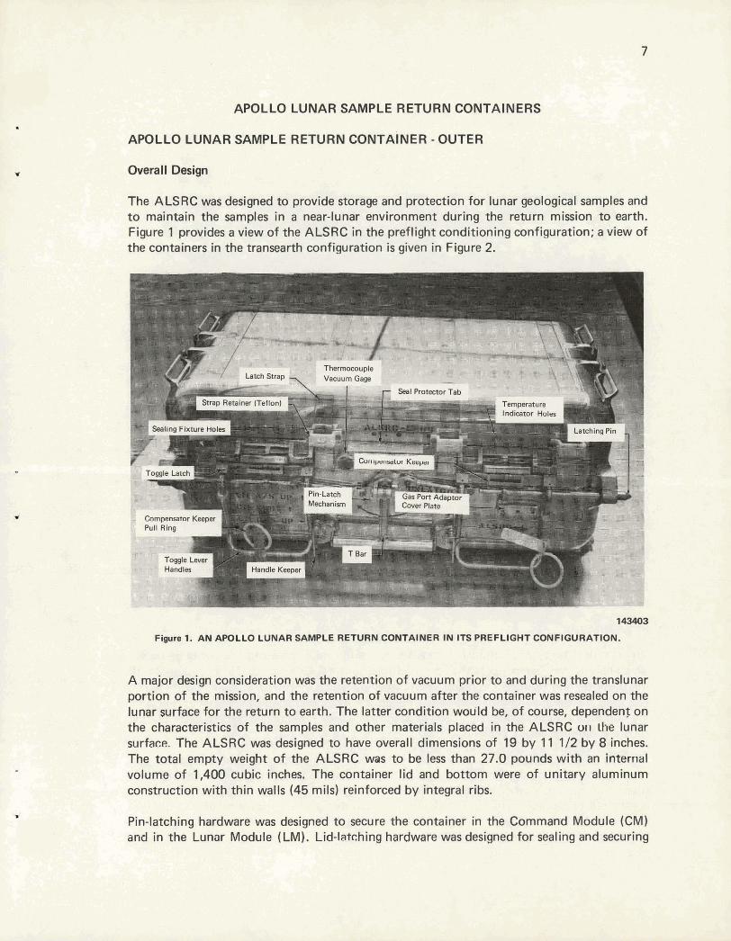
The ALSRC was designed to provide storage and protection for lunar geological samples and to maintain the samples in a near-lunar environment during the return mission to earth. Figure 1 provides a view of the ALSRC in the preflight conditioning configuration; a view of the containers in the transearth configuration is given in Figure 2.
I C o r n ~ o r K e e p e r Pull Ring
=as ron Aclaptor h e r Plate
figam s. AM &PDLLO LUNAR W@t6 &'Fu$M GMVTA~NBR INlITS PREFLI0)I'F QbNFi~RfitlCbN.
A major design consideration was the retention of vacuum prior to and during the translunar portion of the mission, and the retention of vacuum after the container was resealed on the lunar surface for the return to earth. The latter condition would be, of course, dependenf on the characteristics of the samples and other materials placed in the ALSRC o11 the lunar surface?. The ALSRC was designed to have overall dimensions of 19 by 11 112 by 8 inches. The total empty weight of the ALSRC was to be less than 27.0 pounds with an Internal volume of 1,400 cubic inches. The container lid and bottom were of unitary aluminum construction with thin walls (45 mils) reinforced by integral ribs.
hardware was designed to secure the container in the Command Module (CM) was designed for sealing and securing
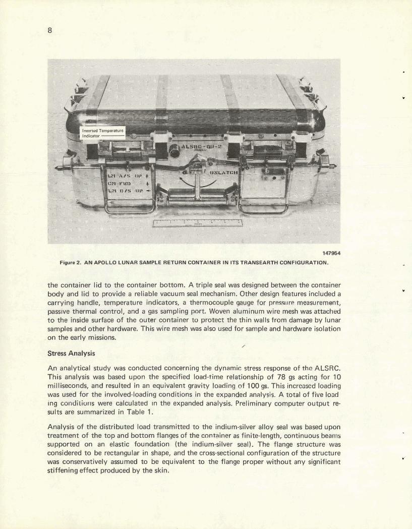
the container lid t o the container bottom. A triple seal was designed between the container body and lid t o provide a reliable vacuum seal mechanism. Other design features included a carrying handle, temperature indicators, a thermocouple gauge for presslire measurement, passive thermal control, and a gas sampling port. Woven aluminum wire mesh was attached to the inside surfam o f the outer container to p~oTeCt the thin walls f rom damage by lunar samples and othsr hardware. This wire mesh was also used for sample and hardware isolation
. on the early missions. /
Stress Analysis
A n analytical study was conducted concerning the dynamic stress response of the ALSRC. This analysis was based upon the specified load-time relationship o f 78 gs acting for 10 milliseconds, and resulted in an equivalent gravity loading o f 100 gs. This increased loading was used for the involved-loading conditions in the expanded analysis. A total sf five load ing condiliuris were calculated In the expanded analysis. Preliminary computer output re- sults are summarized i n Table 1.
Analysis o f the distributed load transmitted t o the indium-silver alloy seal was based upon treatment of the top and bottom flanges of the cnntainer as finite-length, continuous b a r n s supported on an elastic foundation (the indium-silver seal). The flange structure was considered t o be rectangular in shape, and the cross-sectional configuration of the structure was conservatively assumed t o be equivalent to the flange proper without any significant stiffening effect produced by the skin.
Table I Applied loading to the flange
SUMMARY OF PRELIMINARY STRUCTURAL AND structure was considered to be STRESS ANALYSIS RESULTS FOR concentrated a t those points that THE ALSRC OUTER CONTAINER correspond to the location of the
Member Load Unity Safety Maximum ribs which are underneath the TV ~ondition(1) Check Factor stress latch straps. The foundation mod-
ulus (ratio of the distributed load Support Brackets required to produce a given
Left Front 6 0.895 1.12 ! Left Rear 5 0.885 1.12 !
deformation of-the seal) used was
Right Front 6 0.905 1.10 ! determined experimentally by uti- Right Rear 5 0.831 1.20 49.8 lizing a seal-flange configuration
based upon the present design. Support Ribs
Left Front Left Rear Riaht Front
6 0.598 1.67 5 0.602 1.66
35'9 Programs for the computer were 36.1 6 0.692 1.44 41.5 written to calculate the load -
Right Rear 5 0.713 1.40
Solid Ribs
0.115 Web 1 0.635 2.36 6 0.792 1.26 4 1 .lo3 0.91
0.230 Web 1 0.620 2-42 6 0.426 . 2.35
0.420 Web 1 0.723 2.08 6 0.520 1.92
42.8 distribution produced in the indi- um-silver seal by selected latch forces. Bending and torsional
25.4 47.5 stresses, deflect~ons O f the flanyt!~, 66.2 and corresponding deformation of 24.8 the seal were also determined. 25.6 28.9 31.2 Thermal Considerations
Wide Flange Ribs In designing the ALSRC it was 0.040 Web 1 0.879 1.71
5 0.898 1 .11 35.2 necessary to consider the lunar 53.9
0.1 00 Web 1 0.694 2.16 278 environmental conditions; namely, 5 0.431 2.32 25.9 the extreme cold of the shaded
Skin surface and the heating ability of the unattenuated solar rays. The
1 0.740 2.02 29.6 6 0.545 1.93 32.7 location of the ALSRC on the
lunar surface during the mission (1 Load Conditions: 1 - 1 112 atmospheres, 2 - 1 atmosphere, 3 - 1 at- became of utmost importance,
mosphere plus 100 gs on the bottom, 4 - 1 atmosphere plus 40 gs on the right end, b - 1 atmosphere PIUS 100 gs on the back, and since this determined the degree 6 - I atmosphere PIUS 100 gs on the front. of i t s environmental exposure.
There were two major design areas of the ALSRC that were affected
by the aforementioned environmental conditions: (1) it was necessary to be sure that the sun's rays would not melt the indium-silver alloy used in the metallic portion of the seal and that the extreme cold would not harden the elastomer 0 rings; (2) it was necessary to know that the difference in the coefficients of expansion of the steel straps and the aluminum ALSRC lid would not cause an unacceptable variation in the closing force i f a large temperature shift occurred. These problems had to be resolved by using some method of passive thermal control.
The first step in dealing with the problem was to determine the lunar exposure that would be experienced by the ALSRC during i t s stay on the lunar surface. Initial information

received from NASA indicated that the ALSRC would be placed in the sun during the mission. Therefore, steps had to be taken to protect the ALSRC from overheating. The absorptivity and emissivity of the ALSRC surfaces had to be the controlling thermal factors, since only passive thermal control was permitted. It was determined that i f the mean ratio of absorptivity to emissivity was 0.9, the ALSRC temperature would not exceed 680 C for the projected time of exposure. This equilibrium temperature was acceptable, and the proper ratio could be achieved by coating the ALSRC external surfaces with aluminum oxide. The initial training hardware was plasma sprayed with aluminum oxide, as seen in Figure 3. However, before the first mission, NASA decided that the ALSRC would remain in the shade during its stay on the lunar surface since it would remain on the Modular Equipment Stowage Area (MESA) rather than be transported on the tool carrier. Therefore, it was necessary to take steps to prevent the ALSRC from getting too cold rather than too hot.
125716
F i r e 3. AN ALUMINACOATEU AWLLO LUNAR SAMPLE RETURN CONTAINER.
It was determined that highly polished external surfaces would afford the best protection from the cold. It was further determined that the strap latch system would function, but that Viton A 0 rings in the seal would harden to such a degree that it would be impossible tc close the ALSRC. It was therefore necessary to find a substitute for the Viton A, Compressibility-versus-temperature tests were conducted, and fluorosilicone 0 rings were found to function satisfactorily at temperatures as low as -460 C. This information was transmitted to NASA and they approved the use of the fluorosilicone material for the 0
rings. The aluminum oxide coating requirement was deleted for production items, and al l subsequent flight hardware was produced with highly polished surfaces.
Lid-Latching Mechanism
The lid was designed to be held in place by four toggle latches, as can be seen in Figure 1. The two strap latches consisted of four high-strength straps connected to toggle lever handles. The four straps were anchored on the rear side of the container (Figure 4), spanned across the lid, and toggled down on the front side of the container. There were two straps connected to each handle; thus, each of the two strap-latch assemblies applied a clamping force a t four points on the seal. The straps and anchor pins were constructed of Type 17-4 PH stainless steel that was heat treated to a 160,000-psi tensile strength. The toggle handles consisted of a threepiece brazed construction of Type 17-4 PH and Type 304L stainless steel and were designed for easy manipulation by an --+ronaut in a space .-lit.
F i ~ r e 4 . REAR VIEW OF THE APOLLO LUNAR SAMPLE RETURN CONTAINER SHOWING THE STRAP CONNECTIONS.
The latch was designed to exert a clamping force of 1,000 pounds per strap; however, laboratory tests indicated that the most reliable seals were obtained with a 270-pound force per strap on the outbound seal and a 665-pound force per strap on the inbound seal. These loads required applying a force 10 the toggle handle of 4.5 pounds to unlatch on the lurlar
surface and 11.0 pounds to relatch. Final strap tension was set using shims at the point of attachment on the rear of the ALSRC.
When fully engaged, the handles were locked against the ALSRC by a spring handle keeper which had to be pushed aside to release the handle.
Pin-Latching Hardware
The pin-latching hardware was the system that was required to secure the ALSRC in the space capsule stowage compartments. The system had to be compatible with both the LM and CM. The extreme conditions to which the system was to be subjected were: (1) a random vibration simulating the launch and boost phases of the atmospheric flight while the container was packed in the outbound configuration; (2) a simulated reentry acceleration test of 20 gs on each of three orrhogonal axes for a durat~on of 30 seconds will1 Llre container packed with samples, and (3) a maximum shock luad uf 78 gs for a duration of 10 milliseconds on the loaded container.
The pin-latch mechanism was designed as an integral part of the T-bar carrying handle. The handle was connected through a linkage system to the latch pins so that rotation of the handle extended or retracted the pins. Stops a t the extremes of handle rotation, combined with a hard linkage system, provided positive indication of the latched or unlatched condition of the pins. The pin-latch mechanism and T-bar handle can also be seen in Figure
The T-bar handle was adaptable for operation with either hand. A clockwise rotation of the handle retracted the latching pins and allowed the container to be inserted into or removed from the stowage compartment; a counterclockwise rotation extended the latching pins into the mating holes in the stowage compartment, thus locking it securely in place.
Locking the pins in position was a~mplished by folding the handle downward against the box and forcing the handle into its latched position. The handle was retained in this position by two springloaded ball detents in the handle. A force of 1.5 pounds was required to unlatch the handle. This force, combined with the low mass of the handle, was sufficient to insure that the imposed shock and vibration conditions would mot disldge the handle. The pin linkage was designed to take an end-force column loading of 500 pounds, and the handle would withstand a rotation torque of 60 inch pounds. The latch pins were designed to withstand 100 gs in shear with a safety factor of 4.
Materials of construction were Type 6061-T6 aluminum tor the handle and lir~kage and Type 17-4 PH stainless steel for the latch plns. The larch pins were t e a t treated tn n Rockwell-C hardness of 40 (Rc - 40).
Seal Mechanism
The ALSRC seal had one main function-to keep outside contamination from reaching the lunar samples. To accomplish this task, it was necessary for the seal to be vacuum tight, as the atmosphere on the lunar surface is equivalent to a high vacuum on earth. Two important seal-design considerations were essential: (1) that the seal must not introduce any

contaminants into the system, and (2) that a satisfactory seal must be made that utilized only a small force. The force limitation was due to the fact that the astronaut's limited agility prevented him from exerting excessive force in closing the ALSRC.
Molten-Metal Seal - Taking the two considerations into account, it appeared that a molten-metal seal would be the most satisfactory. In view of this conclusion, development activities were directed toward three main areas: (1) heater design, (2) thermal studies, and (3) tinning experiments. The entire seal concept included the need for an electric heater that would melt the sealing metal (contained in a trough) which, when molten, would adhere to the tinned mating surface and, when solidified, would form a seal. Details pertaining to the technical endeavors associated with the sealing effort are beyond the scope of this report. However, after several months of work, the conclusion was reached that this method of sealing the ALSRC was impractical for several reasons: (1) more electrical power would be required to melt the seal than was available from the spacecraft; (2) an excessive amount of time would be required for the seal to solidify in the lunar vacuum, and (3) the problem of tinning an aluminum surface to adhere to a suitable sealing metal proved to be too formidable. Therefore, the concept of a molten seal for the ALSRC was abandoned.
Metallic Seals- In the vacuum industry, all-metal sealsare in common usage. Gold 0 rings, steel K rings, and soft aluminum gaskets are examples of these metallic devices that provide satisfactory vacuum seals. However, they all have one thing in common that made them unsatisfactory for use with the ALSRC; namely, they require too large a sealing force.
ALSRC seal development work, therefore, concentrated on designing an all-metal seal with a knife edge that w w Id cut into a soft metal to form a seal. As with the molten-seal concept, the soft metal would be placed in a trough in the body of the ALSRC. Then, a mating knife edge would be machined into the lid that would cut into the soft metal to make the seal. Since it was desirable to have a sealed ALSRC on the outbound journey as well as inbound, it would be necessary to effect two seals with the same surfaces. This double sealing would be possible with a proper design of the knife edge and by applying additional sealing force for the inbound seal. However, alignment for the second seal proved to be extremely critical and beyond the capabilities of the ALSRC hinge system. Therefore, the all-metallic seal concept was also considered to be unacceptable.
Composite Seal - NASA personnel were then advised of the problem and they agreed to using a fluorosilicone 0 ring for the outbound seal, provided a metallic seal was used inbound and that the lunar samples could be isolated from the fluorosilicone 0 ring.
Concurrent with the main seal development work, a project was undertaken to determine the effect of lunar dust on the ALSRC. The results indicated that it would be necessary to protect the sealing surface from being contaminated with lunar dust while the ALSRC was being packed. Therefore, it would be necessary to include a dust shield as an integral part of the ALSRC seal design.
The final composite seal design concept, as formulated, included a knife edge in the ALSRC lid, a trough of soft metal in the body, 0 rings in the lid and body, and a throwaway seal protector to cover the lid and body sealing surfaces during translunar flight and when the ALSRC was open on the lunar surface. A cross section of the final seal design for the
translunar configuration is presented in Figure 5, and for the transearth configuration in Figure 6.
Fluorwilicone
Outboun
Elastomer Seals
d Seal Protector -
Knife Edge
Seal Alloy (90% In, 10% Ag)
Fiwra 5. T R M L U N A R SEAL CQNFlGURATlnN
An indiumsilver alloy (90% In-10% Ag) was chosen as the material for the metallic seal and was purchased as wire with a 105mil-square cross section. The alloy was carefully rolled into the trough in the ALSRC body. This rolling operation worked the alloy against the walls of the groove, thereby effecting a seal. It was also very important that the alloy wire be flush with the top of the trough, as the initial knife-edge penetration into the soft metal was only 7 to 9 mils.

Fluorosilicone 0 Rings
- Knife Edge
-Seal Alloy (90% In, 10% Ag)
Fipre 6. TRANSEARTH SEAL CONFIGURATION.
Placing the 0 rings in their respective groove also required care. Since the 0 rings were long and easily stretched, care was taken not to stretch the 0 ring in part of the groove and squeeze it in other sections. This squeezing resulted in "hardr*.areas which prevented enough movement of the lid to permit a seal to be made at the "soft" or stretched areas.
The final ALSRC vacuum seal system was capable of making a seal with an integrated leak rate of less than 1 x 10⁻⁷ std cclsec.
Seal Cover and Spacer
For the outbound journey, the two fluorosilicone 0 rings were sealed against a tetraf luoroethylene-hexaf luoropropylene i F EP) copolymer Teflon seal protector that was 60

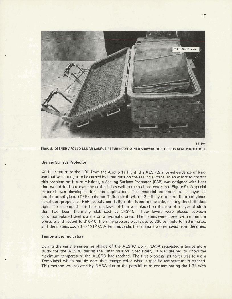
mils thick. This Teflon seal protector is shown separately in Figure 7, and fitted on the ALSRC in Figure 8. The seal protector was removed just before closing the container on the lunar surface to permit the knife edge on the lid to penetrate the indium-silver gasket in the trough of the container. This design provided the all-metal seal on the innermost edge of the flange, with the two fluorosilicone 0 rings providing secondary sealing.
147252 Figure 7. SEAL AND DUST PROTECTORS.
Because of the probability of lunar dust collecting on the indium-silver sealing surface, the Teflon seal protector was equipped with a thermally formed dust protector made of Smil-thick F EP Teflon film. The protector was welded to the inner edge of the Teflon seal protector (Figure 7). This dust protector was formed to f i t the irregular contour of the container flanges by using a compression-type aluminum mold. The film was stretched over the female part ot the mold and held in place with a glass-silicone electrical tape. The other half of the mold was installed and the assembly placed between the heated platens of a hydraulic press. The platens were closed until the top surface of the mold was touching the platen. The assembly was held in this position until the mold temperature reached 1770 C, at which point sufficient pressure was applied to close the mold. The temperature was raised to 2040 C and held for one hour, then the piece was thermally stabilized by placing it in an oven on a flat plate at 790 C for three hours. Finally, it was cooled at 100 C per hour to room temperature, trimmed to size, and welded to the spacer with an electrical soldering iron with a special tip.
The surface finish of the Teflon seal protector was critical. Considerable difficulty was encountered in obtaining a seal between the Teflon and 0 rings. In most cases it was necessary to hand polish the Teflon to effect a seal. All seal protectors were installed in a test ALSRC and leak checked before being accepted as flight hardware.
I Protector
131904
Figure 8. OPENED APOLLO LUNAR SAMPLE RETURN CONTAINER SHOWING THE TEFLON SEAL PROTECTOR.
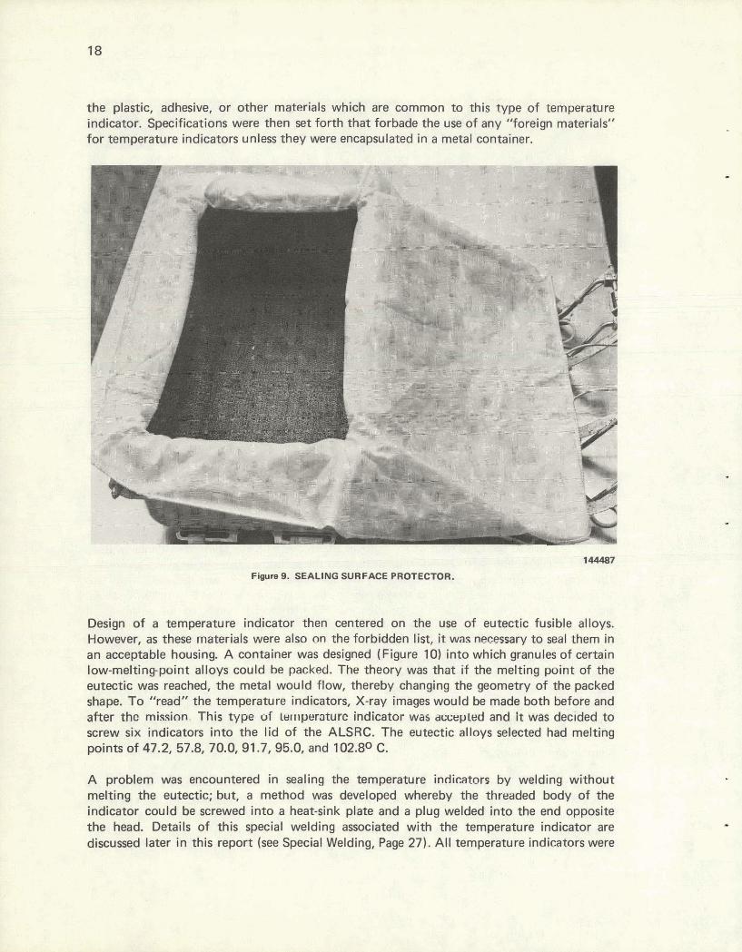
Sealing Surface Protector
On their return to the LRL from the Apollo 11 flight, the ALSRCs showed evidence of leak- age that was thought to be caused by lunar dust on the sealing surface. In an effort to correct this problem on future missions, a Sealing Surface Protector (SSP) was designed with flaps that would fold out over the entire lid as well as the seal protector (see Figure 9). A special material was developed for this application. The material consisted of a layer of tetrafluoroethylene (TFE) polymer Teflon cloth with a 2-mil layer of tetrafluoroethylene- hexafluoropropylene (F EP) copolymer Teflon film fused to one side, making the cloth dust tight. To accomplish this fusion, a layer of film was placed on the top of a layer of cloth that had been thermally stabilized at 2430C. These layers were placed between chromium-plated steel platens on a hydraulic press. The platens were closed with minimum pressure and heated to 3100 C, then the pressure was raised to 335 psi, held for 30 minutes, and the platens cooled to 171 C. After this cycle, the laminate was removed from the press.
Temperature Indicators
During the early engineering phases of the ALSRC work, NASA requested a temperature study for the ALSRC during the lunar mission. Specifically, it was desired to know the maximum temperature the ALSRC had reached. The first proposal set forth was to use a Ternpilabel which has six dots that change color when a specific temperature is reached. This method was rejected by NASA duc to the possibility of contaminating the LR L with
the plastic, adhesive, or other materials which are common to this type of temperature indicator. Specifications were then set forth that forbade the use of any "foreign materials" for temperature indicators unless they were encapsulated in a metal container.
144487
Figure 9. SEALING SURFACE PROTECTOR.
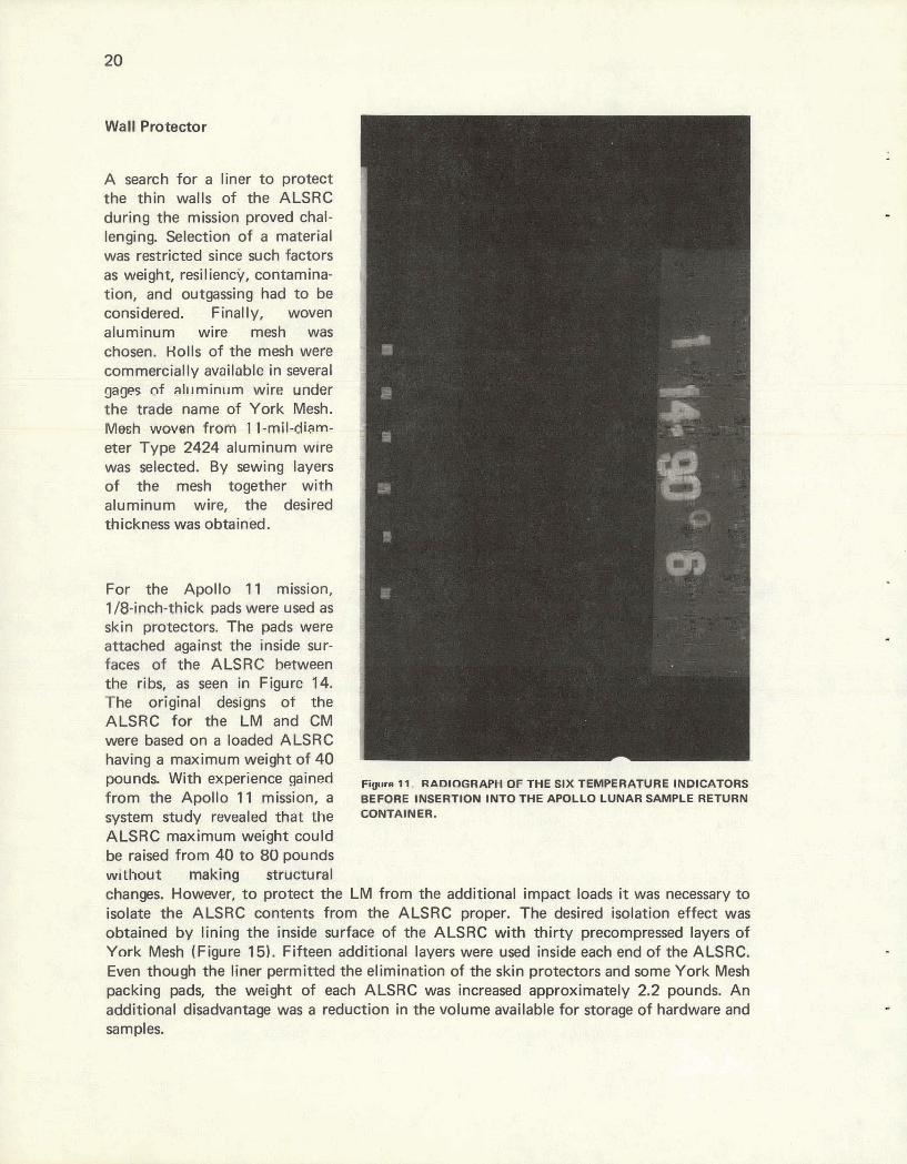
Design of a temperature indicator then centered on the use of eutectic fusible alloys. However, as these materials were also on the forbidden list, it was necessary to seal them in an acceptable housing. A container was designed (Figure 10) into which granules of certain low-meltingpoint alloys could be packed. The theory was that if the melting point of the eutectic was reached, the metal would flow, thereby changing the geometry of the packed shape. To "read" the temperature indicators, X-ray images would be made both before and after thc m i ~ i n n . This type of Lwr~peraturc indicator was awepled and it was decided to screw six indicators into the lid of the ALSRC. The eutectic alloys selected had melting points of 47.2,57.8, 70.0,91.7,95.0, and 102.8O C.
A problem was encountered in sealing the temperature indicators by welding without melting the eutectic; but, a method was developed whereby the threaded body of the indicator could be screwed into a heat-sink plate and a plug welded into the end opposite the head. Details of this special welding associated with the temperature indicator are discussed later in this report (see Special Welding, Page 27). All temperature indicators were

0.05- 1- wide Slot I I / Engrave Temperature
Indicator Number on this Surface
- I D 3 2 UNF-2A Thread
0.01 " x 450 Chamfer
Laser Beam Weld
I
Weld Plug After Inserting Eutectic, Before Machining Threads
Figure 10. TEMPERATURE INDICATOR.
radiographed after fabrication to insure that the eutectic had not melted during welding arid to give a "before" shot of the packed material prior to i t s insertion into the respective temperature indicator holes in the ALSRC body (see Figure 11). The temperature indicators for each A LSRC were shipped to the NASA-MSC in a separate package with the A LSRC and were installed after the preflight temperature conditioning of the ALSRC.
After the lunar mission, the temperature indicators were returned to the Y-12 Plant for evaluation. At that time they were radiographed and the film was compared to the "before" shots to determine if the eutectic configuration had undergone a change due to melting. Some difficulty was encountered in determining if some of the temperature indicators had melted. In order to verify that melting had occurred, all of the questionable indicators were carefully cut open and a visual inspection made. Experimentation and inspection revealed that surface tension prevented the metal from flowing freely in some cases. However, i f the melting point of the eutectic was reached, and no flow occurred, it was st i l l possible to detect melting, since the surface of the eutectic changed completely. The original as-packed granular texture was replaced by a glossy surface containing small globules, as noted in Figure 12, In some cases, only limited flow occurred, as Figure 13 indicates.
Although "reading" the temperature indicators proved to present more of a problem than was originally expected, the indicators did give a satisfactory indication of the maximum temperature range experienced by the ALSRC during the lunar mission.
Wall Protector r A search for a liner to protect the thin walls of the ALSRC during the mission proved chal- lenging. Selection of a material was restricted since such factors as weight, resiliency, contamina- tion, and outgassing had to be considered. Finally, woven aluminum wire mesh was chosen. Holls of the mesh were commercially available in several gages of pl~~rninurn wire. under the trade name of York Mesh. Mesh woven from 'I 1-mil-diam- eter Type 2424 aluminum wire was selected. By sewing layers of the mesh together with aluminum wire, the desired thickness was obtain'd.
For the Apollo 11 mission, 1 /0-inch-thick pads were used as skin protectors. The pads were attached against the inside sur- faces of the ALSRC &ween the ribs, as seen in Figure 14, The original designs of the ALSRC for the LM and CM were based on a loaded ALSRC having a maximum weight of 40
from the Apollo 1 1 mission, a BEFORE INSERTION ~NTO THE APOLLO LUNAR SAMPLE RETURN
system study revealed that the ~NTAINER.
ALSRC maximum weight could .be raised from 40 to 80 pounds without making srrumnl changes. However, to protect the LM from the additional impact loads it was necessary to isolate the ALSRC contents from the ALSRC proper. The desired isolation effect was obtained by lining the inside surface of the ALSRC with thirty precompressed layers of York Mesh (Figure 15). Fifteen additional layers were used inside each end of the ALSRC. Even though the liner permitted the elimination of the skin protectors and some York Mesh packing pads, the weight of each ALSRC was increased approximately 2.2 pounds. An additional disadvantage was a reduction in the volume available for storage of hardware and samples.

Design of the LMs used after the Apollo 14 mission was such that isolation liners were not required for protection. However, to provide contin- ued protection for the ALSRCs and the lunar sam- ples, quarter-inch-thick liners were used for the balance of the Apollo program.
Forging the ALSRC Blank
Ingots of Type 7075 alumi- num (12" D and 12" L, Figure 16) were heated to 3710 C
Fimn 12. TEMPERATURE INDICATOR CONTAINING A SMOOTH and then side forged (Figure SPHERE. 17) to about four inches thick,
producing a blank (roughly 19" x 19") with roundrkl sides. These flattened blanks were then cut to a size which would f i t into the ALSRC body blank forging die cavity (roughly 19 112" x 12").
The prepared aluminum blank was then heated to 3710 C, the dies were heated wit@ torches, and then the ALSRC body was forged in one step. A view of the resulting ALSRC body blank is present- ed in Figure 18. To allow stock for the handle attach- ments and other bosses to be
Fiwa 13. TEMPERATURE INDICATOR SHOWING A LIMITED FLOW machined from the blank, it
DURING MELTING. was necessary to forge the front wall to a thickness of about 1 112 inches. In order to
keep the die forces equalized, the rear wall was also forged to thesame thickness.,A similar forged blank of Type 7075 aluminum was madc for thc ALSRC lid.
Heat Treatment of the ALSRC
The forged blanks were semimachined before heat treatment to remove the bulk of the excess stock and to leave, as nearly as possible, a uniform amount of stock for final removal.
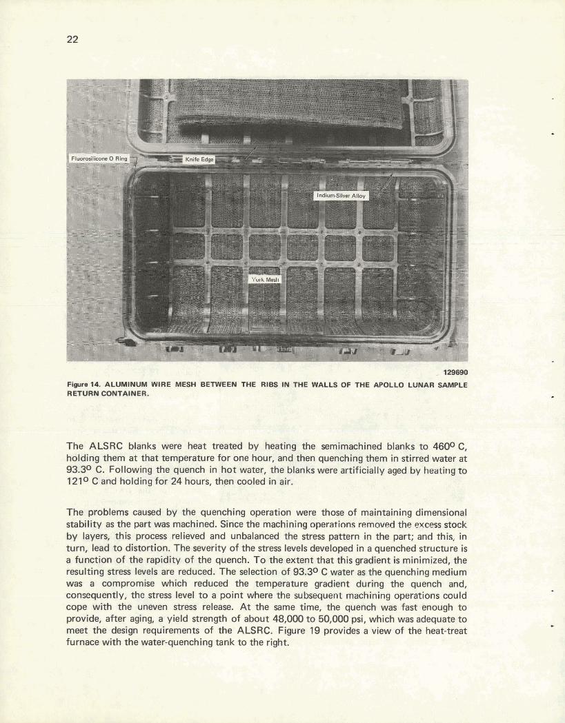
1- Figure 14. ALUMINUM WlRE MESH BETWEEN THE RIBS IN THE WALLS OF THE APOLLO LUNAR SAMPLE RETURN CONTAINER.
The ALSRC blanks were heat treated by heating the semimachined blanks to 4600C, holding them at that temperature for one hour, and then quenching them in stirred water at 93.30 C. Following the quench in hot water, the blanks were artificially aged by heating to 1210 C and holding for 24 hours, thpn cooled in air.
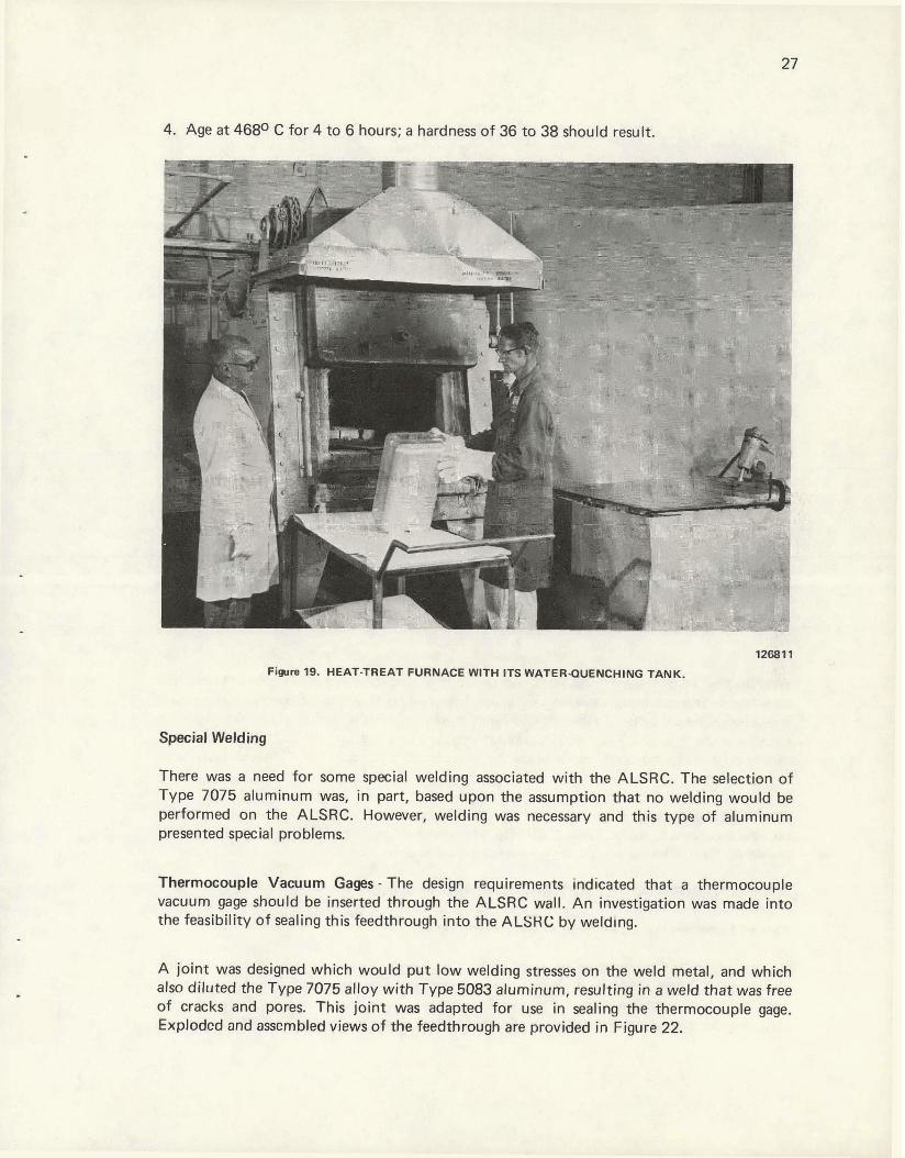
The problems caused by the quenching operation were those of maintaining dimensional stability as the part was machined. Since the machining operatinns removecl the excess stock by layers, this process relieved and unbalanced the stress pattern in the part; and this, in turn, lead to distortion. The severity of the stress levels developed in a quenched structure is a function of the rapidity of the quench. To the extent that this gradient is minimized, the resulting stress levels are reduced. The selection of 93.30 C water as the quenching medium was a compromise which reduced the temperature gradient during the quench and, consequently, the stress level to a point where the subsequent machining operations could cope with the uneven stress release. At the same time, the quench was fast enough to provide, after aging, a yield strength of about 48,000 to 50,000 psi, which was adequate to meet the design requirements of the ALSRC. Figure 19 provides a view of the heat-treat furnace with the water-quenching tank to the right.
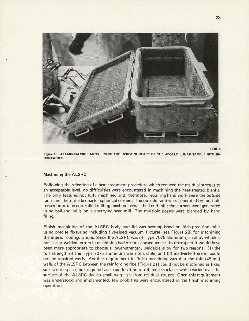
131915
Figure 15. ALUMINUM WIRE MESH LINING THE INSIDE SURFACE OF THE APOLLO LUNAR SAMPLE RETURN CONTAINER.
Machining the ALSRC
Following the selection of a heat-treatment procedure which reduced the residual stresses to an acceptable level, no difficulties were encountered in machining the heat-treated blanks. The only features not fully machined and, therefore, requiring hand work were the outside radii and the outside quarter spherical corners. The outside radii were generated by multiple passes on a tapecontrolled milling machine using a ball-end mill; the corners were generated using ball-end mills on a cherrying-head mill. The multiple passes were blended by hand filing.
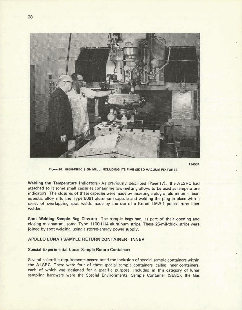
Finish machining of the ALSRC body and lid was accomplished on high-precision mills using precise fixturing including five-sided vacuum fixtures (see Figure 20) for machining the interior configurations. Since the ALSRC was of Type 7075 aluminum, an alloy which is not easily welded, errors in machining had serious consequences. In retrospect it would have been more appropriate to choose a lower-strength, weldable alloy for two reasons: (1) the full strength of the Type 7075 aluminum was not usable, and (2) inadvertent errors could not be repaired easily. Another requirement in finish machining was that the thin (45-mil) walls of the ALSRC between the reinforcing ribs (Figure 21) could not be machined as fixed surfaces in space, but required an exact location of reference surfaces which varied over the surface of the ALSRC due to small warpages from residual stresses. Once this requirement was understood and implemented, few problems were encountered in the finish machining operation.
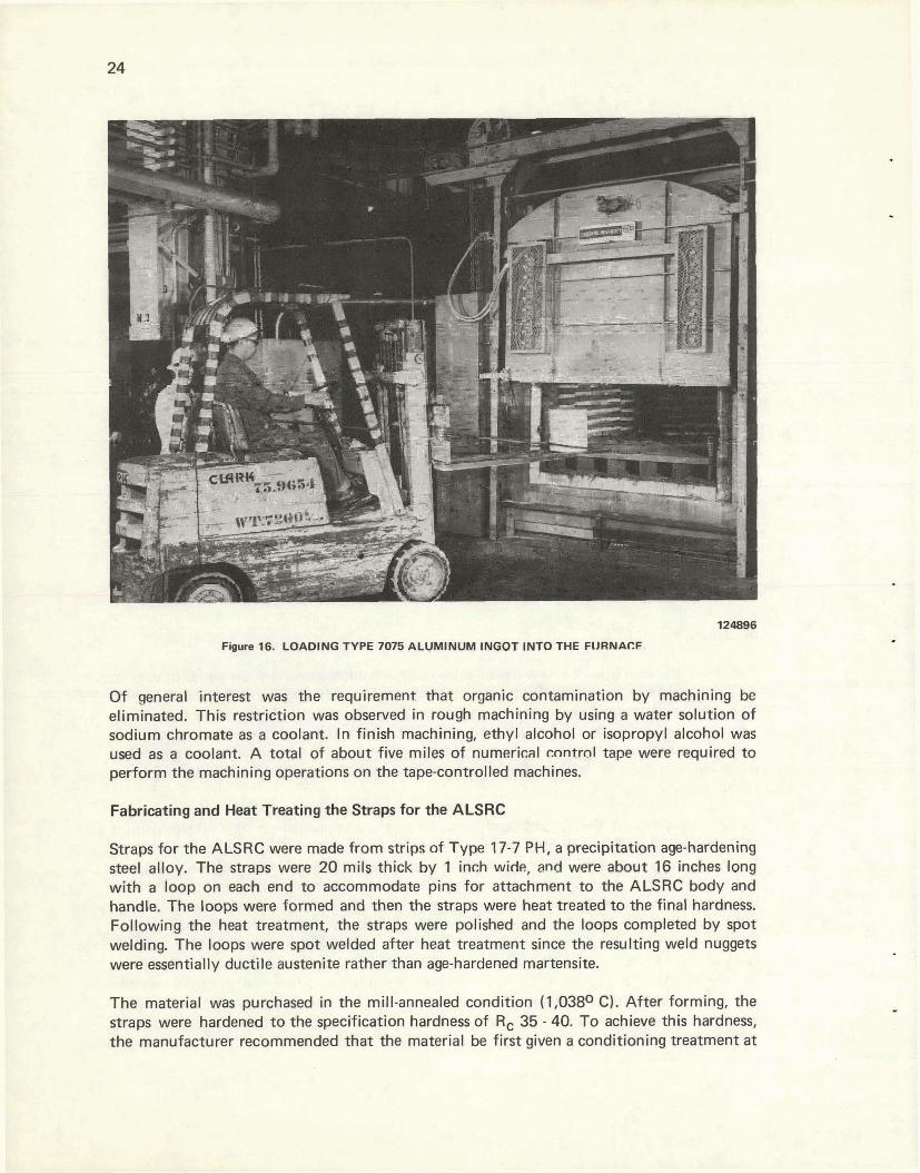
Fig- 16. LOADING TYPE 7075 ALUMINUM INGOT INTO THE FURNACF
Of general interest was the requirement that organic contamination by machining be eliminated. This restriction was observed in rough machining by using a water solution of sodium chromate as a coolant. In finish machining, ethyl alcohol or isopropyl alcohol was used as a coolant. A total of about five miles of numerical cnntrol tape were required to perform the machining operations on the tapecontrolled machines.
Fabricating and Heat Treating the Straps for the ALSRC
Straps for the ALSRC were made from strips of Type 17-7 PHI a precipitation age-hardening steel alloy. The straps were 20 mils thick by 1 inch wide, and were about 16 inches long with a loop on each end to accommodate pins for attachment to the ALSRC body and handle. The loops were formed and then the straps were heat treated to the final hardness. Following the heat treatment, the straps were polished and the loops completed by spot welding. The loops were spot welded after heat treatment since the resulting weld nuggets were essentially ductile austenite rather than age-hardened martensite.
The material was purchased in the mill-annealed condition (1,0380 C). After forming, the straps were hardened to the specification hardness of Rc 35 - 40. To achieve this hardness, the manufacturer recommended that the material be first given a conditioning treatment at
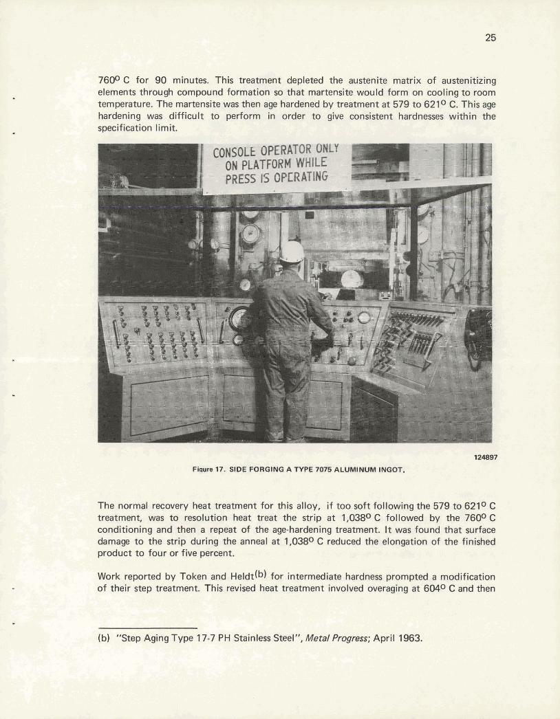
7600 C for 90 minutes. This treatment depleted the austenite matrix of austenitizing elements through compound formation so that martensite would form on cooling to room temperature. The martensite was then age hardened by treatment a t 579 to 6210 C. This age hardening was difficult to perform in order to give consistent hardnesses within the specification limit.
124897
Fieuw 17, SIDE FORGING A TYPE 7075 ALUMINUM INGOT.
The normal recovery heat treatment for this alloy, i f too soft following the 579 to 6210 C treatment, was to resolution heat treat the strip at 1,0380 C followed by the 7600 C conditioning and then a repeat of the age-hardening treatment. It was found that surface damage to the strip during the anneal at 1,0380 C reduced the elongation of the finished product to four or five percent.
Work reported by Token and ~eldt (b) for intermediate hardness prompted a modification of their step treatment. This revised heat treatment involved overaging a t 6040 C and then
(b) "Step Aging Type 1 7-7 PH Stainless Steel", Metal Progress; April 1963.
>
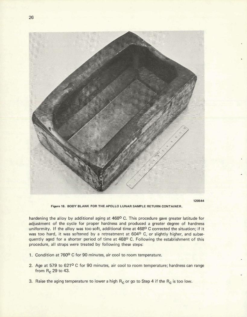
Fwre 18. BODY BLANK FOR THE APOLLO LUNAR SAMPLE RETURN CONTAINER.
hardening the alloy by additional aging a t 468O C. This procedure gave greater latitude for adjustment of the cycle for proper hardness and produced a greater degree of hardness uniformity. If the alloy was too soft, additional time a t 4680 C corrected the situation; if it was too hard, it was softened by a retreatment a t 604O C, or slightly higher, and subse- quently aged for a shorter period of time a t 4680 C. Following the establishment of this procedure, al l straps were treated by following these steps:
1. Condition at 760° C for 90 minutes, air cool to room temperature.
2. Age a t 579 to 621° C for 90 minutes, air cool to room temperature; hardness can range from Rc 29 to 43.
3. Raise the aging temperature to lower a high Rc or go to Step 4 i f the Rc is too low.
4. Age at 468O C for 4 to 6 hours; a hardness of 36 to 38 should result.
:.1i" ,-.i r * .
- ..W --- ;.y - ..i
1-1
Figtre 19. HEAT-TREAT FURNACE WITH ITS WATERQUENCHING TANK.
Special Welding
There was a need for some special welding associated with the ALSRC. The selection of Type 7075 aluminum was, in part, based upon the assumption that no welding would be performed on the ALSRC. However, welding was necessary and this type of aluminum presented special problems.
Thermocouple Vacuum Gages - The design requirements indicated that a thermocouple vacuum gage should be inserted through the ALSRC wall. An investigation was made into the feasibility of sealing this feedthrough into the ALSHC by welding.
A joint was designed which would put low welding stresses on the weld metal, and which also diluted the Type 7075 alloy with Type 5083 aluminum, resulting in a weld that was free of cracks and pores. This joint was adapted for use in sealing the thermocouple gage. Explodcd and osmmbled views of the feedthrough are provided in Figure 22.
Welding the Temperature Indicators - As previously described (Page 17). the ALSRC had attached t o it some small capsules containing low-melting alloys t o be used as temperature indicators. The closures o f these capsules were made by inserting a plug o f aluminum-silicon eutectic alloy into the Type 6061 aluminum capsule and welding the plug in place with a series o f overlapping spot welds made by the use o t a Korad LMW-1 pulsed ruby laser welder.
Spot Welding Sample Bag Closures - The sample bags had, as part o f their opening and closing mechanism, some Type 1100-HI4 aluminum strips. These 25-mil-thick strips were joined by spot welding, using a stored-energy power supply.
APOLLO LlJNAR SAMPLE RETURN CONTAINER - INNER
Special Experimental Lunar Sample Return Containers
Several scientific requirements necessitated the inclusion o f special sample containers within the ALSRC. There were four of 'these special sample containers, called inner containers, each o f which was designed for a specific purpose. Included in this category o f lunar sampling hardware were the Special Environmental Sample Container (SESC), the Gas
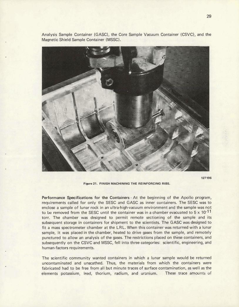
Analysis Sample Container (GASC), the Core Sample Vacuum Container (CSVC), and the Magnetic Shield Sample Container (MSSC).
127196
Figure 21. FINISH MACHINING THE REINFORCING RIBS.
Performance Specifications for the Containers - At the beginning of the Apollo program, requirements called for only the SESC and GASC as inner containers. The SESC was to enclose a sample of lunar rock in an ultra-high-vacuum environment and the sample was not to be removed from the SESC until the container was in a chamber evacuated to 5 x 10⁻¹ torr. The chamber was designed to permit remote sectioning of the sample and i t s subsequent storage in containers for shipment to the scientists. The GASC was designed to f i t a mass spectrometer chamber a t the LR L. When this container was returned with a lunar sample, it was placed in the chamber, heated to drive gases from the sample, and remotely punctured to allow an analysis of the gases. The restrictions placed on these containers, and subsequently on the CSVC and MSSC, fell into three categories: scientific, engineering, and human-factors requirements.
The scientific community wanted containers in which a lunar sample would be returned and unscathed. Thus, the materials from which the containers were
abricated had to be free from al l but minute traces of surface contamination, as well as the lements ~otassium lead. thorium. radium. and' uranium. These trace amounts ul

material had t o be quantitatively evaluated. The containers had t o be capable of withstanding a high-temperature (163O C) bake in a v k u u m environment for outgassing the material, and they had t o be capable of being cleaned t o the same degree as the ALSRC. I n addition, the SESC, GASC, and CSVC were required t o maintain a vacuum as close t o that of the environment in which the samples were collected as possible; ie, they were t o have minimum leak rates past the seals and minimum outgassing rates from the containers
Aluminum End of Transition
Sleeve (Type W36 All
vacuum Gauge HItlRter
(a) Exploded View Laser Subassembly Weld 1
Container and Intcgral Boss Mschined from a Type 7075 Alumtirum Forglng
(b) Assembled View
Figure22. VIEWS OF THE COMPONENTS USED TO ATTACH A THERMOCOUPLE VACUUM GAUGE TO AN APOLLO LUNAR SAMPLE RETURN CONTAINER.
themselves. (The MSSC was not designed as a vacuum container.) Finally, all of the hardware had to withstand sterilization a t 121° C for 96 hours in a vacuum chamber with a pressure of 10-8 torr.
The engineering restrictions were dictated primarily by the spacecraft In which the containers were to fly and the conceivable mission events. In general, the containers had to maintain maximum structural integrity while contributing minimum weight to the spacecraft. The containers had to withstand random vibration, such as that generated by the spacecraft, without a significant increase in the leak rate, and they had to withstand a 78-9 peak shock without losing their structural integrity. The maximum allowable weights for the inner containers were as follows: SESC - 0.83 Ib, GASC - 0.6 Ib, CSVC - 1.2 Ibs, and MSSC - 1.2 I bs.
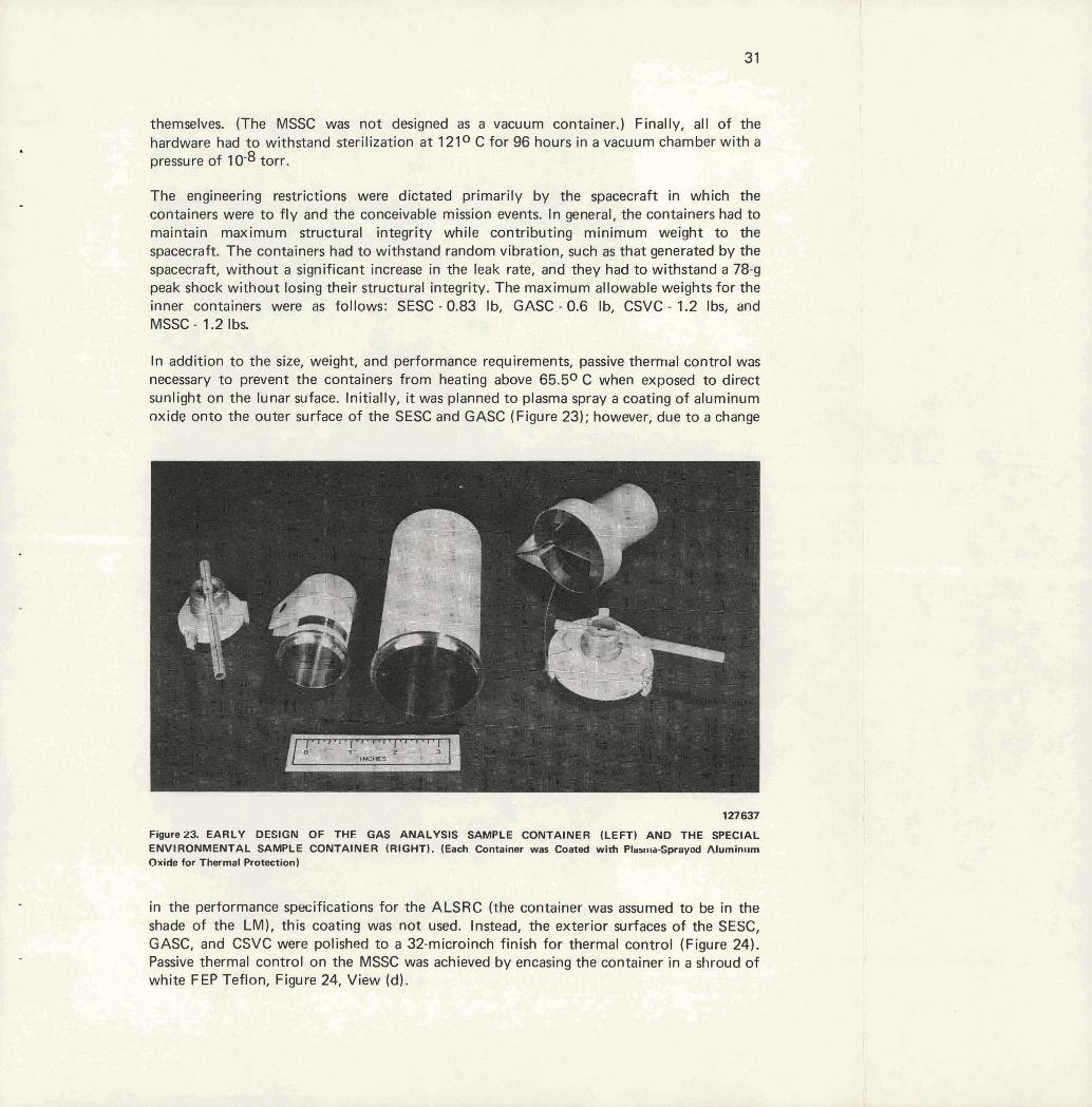
In addition to the size, weight, and performance requirements, passive thermal control was necessary to prevent the containers from heating above 65.50 C when exposed to direct sunlight on the lunar suface. Initially, it was planned to plasma spray a coating of aluminum oxide onto the outer surface of the SESC and GASC (Figure 23); however, due to a change
1 27 637
Figure23. EARLY DESIGN OF THE GAS ANALYSIS SAMPLE CONTAINER (LEFT) AND THE SPECIAL ENVIRONMENTAL SAMPLE CONTAINER (RIGHT). (Each Container was Coated with Plas~~~a-Sprayod Aluminllm Oxide far Thermal Protection)
in the performance specifications for the ALSRC (the container was assumea to De In the shade of the LM), this coating was not used. Instead, the exterior surfaces of the SESC, GASC, and CSVC were polished to a 32-microinch finish for thermal control (Figure 24). Passive thermal control on the MSSC was achieved by encasing the container in a shroud of white FEP Teflon, Figure 24, View (d).

"F . G .
suaiipk- 1 - (c) Cora ampto Vwuum Cottmtner (CSVC) 1
The third set of important design criteria were restrictions due to human-factors considerations; ie, the operability of the containers by an astronaut in lunar gravity. The containers had to be easily carried, readily opened and filled, rapidly sealed, and conveniently stowed within the ALSRC. Since twisting motions were required to close all the inner containers, a major problem was the gripping of the container body by the astronaut during the closing operation. Initially, the plasma-sprayed aluminum oxide coating was rough enough to prevent the SESC and GASC from turning in the astronaut's hand, but when the exteriors were polished, some other mechanism was required. A knurled surface was tried first, but the ultimate solution was a molded aluminum grip assist which clamped in place. The CSVC did not require a grip assist in spite of the polished surface since the diameter was less than that of the SESC, and its length was sufficient to enable the astronaut to grip it securely. The exterior surface of the Teflon shroud on the MSSC was completely covered with vertical saw-tooth ridges as a grip-assist mechanism.
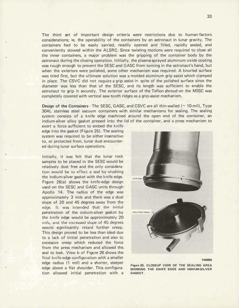
Design of the Containers - The SESC, GASC, and CSVC are al l thin-walled (- 10-mil), Type 304L stainless steel vacuum containers with similar mechanisms for sealing. The sealing system consists of a knife edge machined around the open end of the container, an indium-silver alloy gasket pressed into the lid of the container, and a press mechanism to exert a force sufficient to embed the knife edge into the gasket (Figure 25). The sealing system was required to be either insensitive to, or protected from, lunar dust encounter- ed during lunar surface operations.
Initially, it was felt that the lunar rock samples to be placed in the SESC would be relatively dust free and the only considera- tion would be to effect a seal by crushing the indium-silver gasket with the knife edge. Figure 26(a) shows the knife-edge design used on the SESC and GASC units through Apollo 14. The radius of the edge was approximately 3 mils and there was a dual slope of 20 and 45 degrees away from the edge. II was intended that the initial penetration of the indium-silver gasket by the knife edge would be approximately 20 IIII~S, a11d Ll~e increased slope of 45 degrees would slgnrf~cantly retard further cl'eep. This design proved to be less than ideal due to a lack of initial penetration and also to excessive creep which reduced the force from the press mechanism and allowed the. seal to leak. View b of Figure 26 shows the final knife-edge configuration with a smaller 146689. edge radius (1 mil) and a shorter, steeper
Fi wre2S. CLOgE"p OF THE SEALING AREA edge above a flat shoulder. This configura- SHOWING THE KNIFE EDGE AND INDIUMSILVER tion allowed initial penetration with a GASKET.

L cutting action to expose fresh indium-silver material as the knife edge indented to the
""t" shoulder. The subsequent creep was so slow that the containers could be returned to earth before the press force was completely relieved. This latter design was utilized for the SESC and CSVC units on Apollo Missions 15 through 17.
The indium-silver gasket material used was the same as that used in the ALSRC seal. Since it was to be used as a seal gasket for an ultra-high-vacuum container, the alloy
k) (b) material was vacuum cast into small billets
Figure26. CROSS-SECTION VIEW OF THE KNIFE- and then vacuum extruded into l/&inch-
EDOE CONFIGURATIONS. (Vm a - Ud diameter wire. These vacuum operations A~OIIO 14; ~ k w b - 1 ~ r u d for A~IDIIO 1s through 17) sewed to eliminate most of the entrapped
gas from the gasket material prior to its use. The extruded wire material was then
pressed in a die and formed into a rinpshaped gasket with a rectangular cross section. These gaskets were cleaned with their respective container and then pressed into the groove in the container lid.
In order to embed the knife edge into the gasket and effect a leak-tight seal, the astronaut had to twist the press mechanism with the handle that was provided. Due to the limitations imposed by the space suits and lunar gravity, the maximum torque that could be reliably generated was approximately 32 inch pounds. Thus, the seal had to be made with less than this amount of torque. The torque generated by the astronaut was utilized as efficiently as possible by incorporating a thrust bearing-thrust washer set into the press mechanism, as illustrated in Figure 27. A Bellville washer (ie, a conical spring washer) was also included above the thrust washer. The Bellville washer was completely compressed when a torque of 18 inch pounds was exerted on the handle of the press mechanism. The potential energy stored in the washer was then utilized to keep a slight loading on the seal to prevent leaks from developing.
Early tests showed that leak-tight seals could not be made with simulated lunar dust sprinkled on either the knife edge or the surface of the gasket Thus, some mechanism to prevent dust from coming in contact with these surfaces during the filling operation was required. The seal protectors (Figure 24, View c) were made from Teflon. These protectors remained in place during the filling operation and were removed immediately prior to sealing.
The MSSC, unlike the other inner containers, was not a vacuum container. Its prime purpose was to provide containment for a lunar sample in an environment of a low magnetic field. The MSSC was constructed from Hipernom, an alloy which has a high attenuation factor for magnetic fields. The container had a double-wall construction (Figure 24, View d) in order to maximize its shielding capability, and it had a ribbed Teflon sheath for thermal protection and ease of handling, as discussed earlier. The MSSC can attenuate the earth's
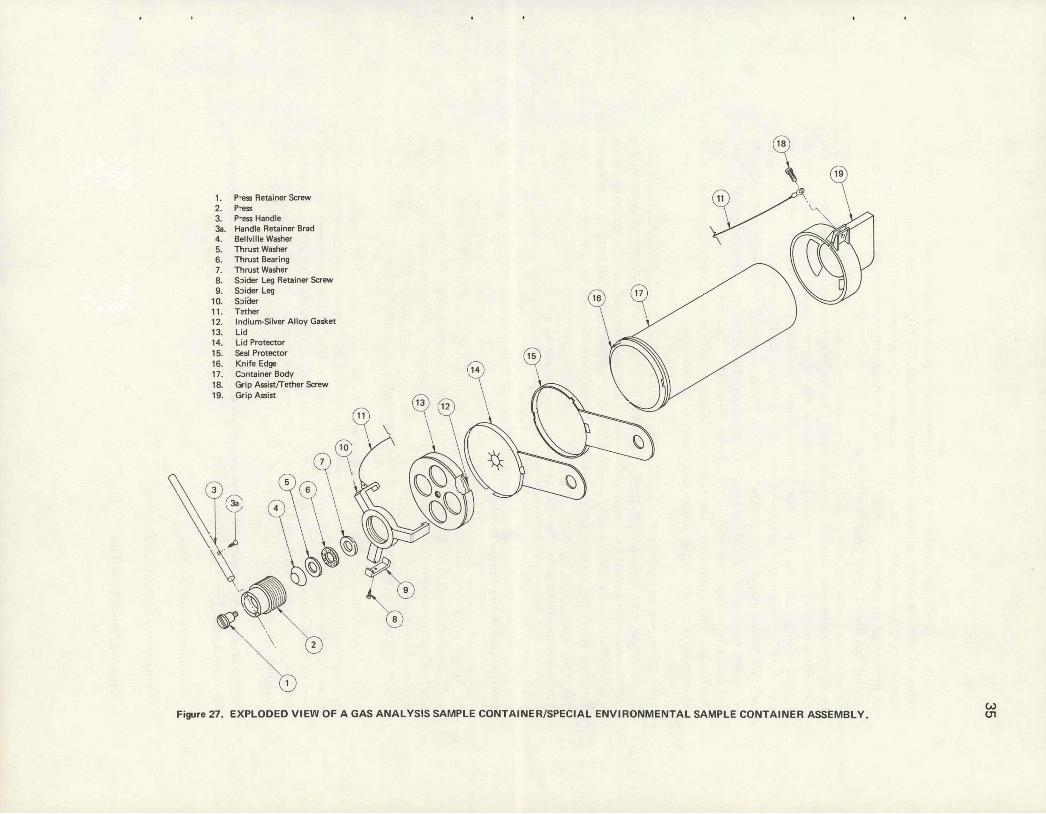
1. Rer Retainer Sfflmr 2. Pna 8 h M l o 3a. Handle Retainer Brad 4. Bellvilla Wsher 5. Thnmw* 8. Thnrst Bearirrg 7. ThrurtWaher a Saidar Leg RatalnerSasw 9. Soi* Le!3 la WIJW 11. T* 12. IndiumSilw Alloy Gasket 13. Lid 14. Lid 16. Sael Protsctor
Fiare 27. EXPLODED VIEW OF A OAS ANALYSIS SAMPLE CONTAINER/SPECIAL'ENV~RONM~NTAL SAMPLE CONTAINER ASSEMBLY.
magnetic field of approximately 50,000 gamma by a factor of approximately 250, well in excess of the required minimum attenuation factor of 50, but less than the desired attenuation factor of 500. There was no exotic sealing mechanism on this container; the lid was merely set in place and twisted until the Teflon locking knurls engaged. This operation required less than 32 inch pounds of torque.
Use of the Containers - Various combinations of the inner containers have been taken to the moon for sample collection activities. Generally, the inner containers were packed inside an ALSRC during both the translunar and transearth portions of the mission, although one extra container was taken outside of the ALSRC. Those packed within the ALSRC had to meet the cleanliness requirements of less than 10 nanograms of nonvolatile contaminants per square centimeter of surface area. The procedure for achieving and certifying this level of cleanliness is described later in this report (Page 50). The container carried outside the ALSRC was only required to be "spacecraft clean", or approximately one microgram of nonvolatile contaminants per square centimeter of surface area.
Figure 28 shows an SSSC and a GASC packed in one of the two ALSRCs for Apollo 13. The aluminum wire mesh around the containers protected them from being damaged by the other hardware in the ALSRC during the mission. On the lunar surface, the containers were slipbd out of the discardable wire mesh shrouds and the samples placed in them. The sealed containers were then repacked in the ALSRC with the other samples for the return to earth. Once they were back on earth in the LRL, the inner containers were held in special chambers prior to the scientific investigation of their contents.
Fluoroplastics in the Apollo Progam
The Apollo program requirement that plastic materials used in the lunar sampling program be of the highest purity, dictated that tetrafluoroethylene (TFE) polymer Teflon and tetrafluoroethylenehexafluoropropylene (I- t P ) copolymer Teflon be employed wherever possible. This requirement was especially true for those parts that would contact the lunar samples or that were enclosed in the ALSRC during the outbound andlor inbound flights.
TF EIFEP fluoropolymer was uniquely qualified for this service because of i t s good thermal and mechanical properties; and, more especially, because the polymer chains were composed of only carbon and fluorine atoms. Film and shapes molded of the polymer are extremely inert to both organic and inorganic chemicals; and, in addition, have low absorption coefficients for other elements and chemical compounds. Because of these latter properties, the danger of contaminating lunar samples with terrestrial products cou Id be minimized.
The following l ist presents the more important developments and items to be discussed later, which used TFEIFEP film and cloth:
1. Contingency Sample Bags
2. Contingency Sample Bag Pouches
3. Documented Sample Bags

PACKED I N THEIR TRANSLUNAR CONFIGURATION.
Aluminum Wire Mesh 1

:-, ill arl,t*>- %-$-&!:*= VyFJqpJ - ,1 Y V --I ' - . - 4. Solar Wind Composition Experiment and Organic Sample Bags
5. Apollo Lunar Sample Return Container Seal Covers and Spacers
6. Apollo Lunar Sample Return Container Sealing Surface Protectors
7. Sample Containment Bags
8. Aseptic Sample Holders and Cord
9. Method for Bleaching Teflon Materials
The fluorofilm selected for this program was a cast type of TFE Teflon with both surfaces made heat bondable by coating them with FEP Teflon. Film of this type was being produced commercialty with only one side bondable at the start of the program; hence, i t s usefulness was seriously limited. However, upon recognizing the potential requirement far a film with both faces heat bondable, industry proceeded to develop the techniques and equipment to apply the FEP coating to both surfaces. The improved film became available in time to meet the schedule for the first Apollo mission.
Material Selection and Evaluation - Weight restrictions dictated that the several types of sample bags be of light-weight construction, yet rugged enough to contain lunar soil and rocks having sharp edges and protrusions. Also, temperatures on the lunar surface might range from -45.50 C in the shade to 65.50 C in the sun. To meet these requirements, 2-mil-thick film was selected for the documented sample bags, while 5-mil-thick film was selected for the contingency sample bags and pouches, and for the solar wind and organic sample bags. The 2-mil-thick film was given a flexure test in liquid nitrogen (-195.50 C) by bending one-inch-wide by four-inch-long strips 180 degrees and straightening them 50 times. This test produced no cracking or other deleterious effects in the film.
Tensile tests were run at room temperature, and tear tests were run at 93.30 C on the 2-mil-thick film. The results indicated that the TFE film would be satisfactory at the anticipated lunar temperatures.
Thermal Stabilization and Bonding- Tetrafluoroethylene Teflon cast films, like molded heavy cross-section pieces, have varying degrees of locked-in stress. Unless corrective action is taken, these stresses usually produce out-of-tolerance and/or warped parts. The NASA specification that all sample bags and related equipment be outgassed at 1630 C under high vacuum for a minimum of 33 hours, required that all Teflon items be thermally stabilized well above this temperature. A stabilizing temperature of 1990 C was selected. For this procedure, all TFE/FEP film and shapes were rough cut or rough machined, heated in a hot- air oven to 199 * 3O C, held at that temperature for a minimum of one hour, then cooled at the rate of 10° C per hour to 93.3O C. At this point they were removed from the oven and allowed to cool to room temperature. All flat mock and film (up to 30 layers) were placed between flat metal plates with sufficient weight to maintain flatness. This treatment allowed the material to be stress relieved. In the case of parts machined from heavy sections with very close tolerances, the treatment was repeated after semimachining.
Bonding of the FEP-coated TFE film to itself was effected at temperatures above 3020 C, using impulse-type sealers or electric soldering irons. A 2-mil-thick polyimide film inserted between the heating element and film prevented fusion to the element.
Bags for Containment of Lunar Samples
A variety of bags were required by Apollo astronauts in order to execute the sample collection activities efficiently and precisely. Large bags were required to hold the various samples as they were collected, and smaller bags were required to enclose individual samples and separate them from other samples. In addition to the samples, certain experiments were also enclosed in bags for the return to earth; specifically, the Solar Wind Composition Experiment and the Organic Control Monitor had special bags. The bags were of two types: (I) those taken individually, such as the Sample Containment Bags (SCB), Solar Wind Composition Container Bags (SWCCB), Organic Sample Bags (OSB), and Protective Sample Bags (PSB); (2) those taken in sets to be dispensed and used individually, such as the Fifteen Documented Sample Bag Dispenser (15-DSBD), Twenty Documented Sample Bag Dispenser (20-DSBD), and Thirty-five Documented Sample Bag Dispenser (35-DSBD). Each of these type uf sa~~~plt! bags Is desct~bed In detail in the topics to follow, the material from which they are fabricated is described in the previous section, Page 36.
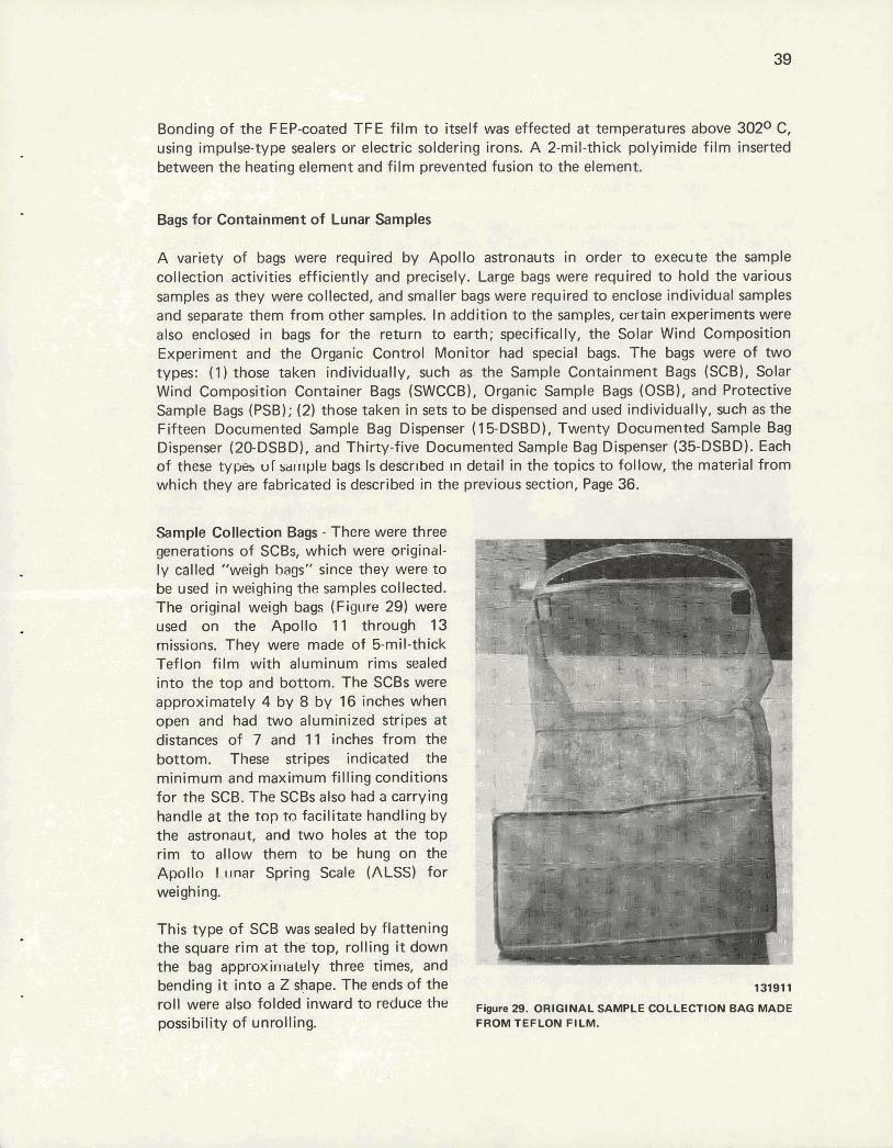
Sample Collection Bags - There were three generations of SCBs, which were original- ly called "weigh bags" since they were to be used in weighing the samples collected. The original weigh bags (Figure 29) were used on the Apollo 11 through 13 missions. They were made of 5-mil-thick Teflon film with aluminum rims sealed into the top and bottom. The SCBs were approximately 4 by 8 by 16 inches when open and had two aluminized stripes at distances of 7 and 11 inches from the bottom. These stripes indicated the minimum and maximum filling conditions for the SCB. The SCBs also had a carrying handle at the top to facilitate handling by the astronaut, and two holes at the top rim to allow them to be hung on the Apolln I-mar Spring Scale (ALSS) for weighing.
This type of SCB was sealed by flattening the square rim a t the top, rolling it down the bag approxiillalely three times, and bending it into a Z shape. The ends of the roll were also folded inward to reduce the possibility of unrolling.
13191 1
Figure 29. ORlGlNAL SAMPLE COLLECTION BAG MADE FROM TEFLON FILM.
Several deficiencies in this design were noted after their use on the early Apollo missions. The Teflon film was found to be quite susceptible to puncture by the sharp lunar rocks and the edges of other sampling equipment. In addition, these SCBs failed to retain their shape adequately when loaded with samples and thus were difficult to pack in the ALSRC.
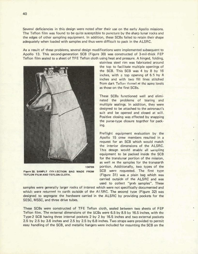
As a result of these problems, several design modifications were implemented subsequent to Apollo 13. This second-generation SCB (Figure 30) was constructed of 3-mil-thick FEP Teflon film sealed to a sheet of TFE Teflon cloth using heat and pressure. A hinged, folding,
stainless steel rim was fabricated around the top to facilitate multiple openings of the SCB. This SCB was 4 by 8 by 16 inches, with a top opening of 6.5 hy 8 inches and with two fill lines stitched tram dark TW~~CIII Ilrrefirl fit the sama Iwds as those on the first SCBs.
These SCBs functioned well and elimi- nated the problems of tearing and multiple sealings. In addition, they were designed to be attached to the astronaut's suit and be opened and closed a t will. Positive closing was effected by snapping the purse-type closure together far pack- ing.
Preflight equipment evaluation by the Apollo 15 crew members resulted in a request for an SCB which would match the interior dimensions of the ALSRC. This deslgn would enable al l ~ ~ i i p l i n g equipment to be packed inside the SCB for the translunar portion of the mission, as well as the samples for the transearth
134789 portion, Additionally, two types of the Fimre3I). SAMPLE CflLLECTlON MAC$ MADE FROM SCB were requested. The first h/pe TEFLON FILM AND TEFLON CLOTH. (Figure 31) Was a plain bag which was
carried outside of the ALSRC and was used to collect "yah samples", These
samples were generally larger rocks of interest which were not specifically documented and which were returned to carth outside of the AISRC. The second type (Figure 32) was designed to segregate the hardware carried in the ALSRC by providing pockets for the SESC, MSSC, and three drive tubes.
These SCBs were constructed of TFE Teflon cloth, sealed between two sheets of F EP Teflon film. The external dimensions of the SCBs wen 6.5 by 8.5 by 16.5 inches, with thc Type-2 SCB having three internal pockets 2 by 2 by 16.5 inches and two external pockets 2.5 by 2.5 by 3.6 inches and 2.5 by 2.5 by 6.8 inches. Two straps were provided to permit easy handling of the SCB, and metallic hangers were included for mounting the SCB on the

Fipure 31. SAMPLE COLLECTION BAG WITH NO POCKETS - TYPE 1.
137219
Figure 32. SAMPLE COLLECTION BAG CONTAINING POCKETS FOR HARDWARE -TYPE 2.
Lunar Roving Vehicle (LRV) and the Apollo Lunar Hand Tool Carrier (ALHTC). The inside surfaces of the Type-2 SCB lid and bottom were covered with a 125-mil pad of aluminum wire mesh to prevent puncturing of the SCB by sharp objects. The lid of the SCB was latched with a mechanism which would engage when the lid was pushed shut. In order to open the lid, the astronaut had to pull away from the SCB with the Teflon loop and lift up. This action released the latch and allowed the lid to be raised.
Contingency Lunar Sample Return Container - During the Apollo missions, sample collection activities did not start immediately after landing on the lunar surface. To ensure that a lunar sample was obtained from each landing site, the astronauts were provided with a sampler to obtain approximately one liter of lunar soil immediately upon reaching the lunar surface. A view of the Contingency Lunar Sample Return Container (CLSRC) used for this activity is given in Figure 33. The CLSRC consisted of an accordian-pleated Teflon bag mounted on a stainless steel scoop ring at the end of an aluminum handle. During the trans- lunar portion of the mission, the handle was folded up, as can be seen in Figure 34, and the CLSRC was stowed in the LM. Upon reaching the lunar surface, the astronaut grasped the end of the CLSRC handle, pulled the nylon cord through it until taut, and secured it in the notch that was provided. This action provided a stiff handle with which to scoop the soil.
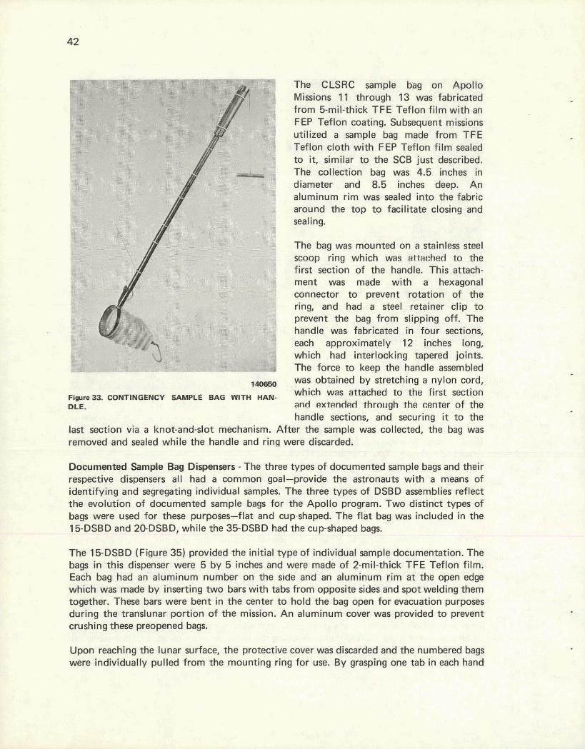
The- ; Q ~ W bagj Apdh Mi@w@. 31, ~ r H @ h - 23 was f&wiim3d from Shil-ttthk TFE Tefian Fi1H w@h am FEa Pur%lon m&m Su-mt nn-9 iu;liL;e$ a bag ma& horn T@L
to it, Qnn39't. @ the SC8 Sua l b wlktion bag was 4.8 i n & ~ ih diemew and 8.6 inches h. .' 4n aSuen'hwrn rim d e d iate @gr@brL soand %he top to fmilMe ~Eosiryl and sealing.
The bag was m w n a on a-s@iidess mmp d q *lct;r -was M to a flmt =@on of ths hrdf'e* Xhjs f'atWi- me^ was m a wifh' s )Isxml;o~ ~~w za PE*WF~C;I.T=*-F- ring, and had -a gee1 rewifter clfp to prevent the bag, f rm &ip&ng off, 'The hatxije ws f&rkltd in fa^ setioniia each a p p r o x ~ m ~ 12 &dms long, which had intetbcklrrg hgered joim. The farce to kwp ttwi hmdls tmemMd
&tainedl by m h i n g a nylon cord,
@wm th center of tb h d e smths, and secur*hg it to toha
18s-t mion Y ~ B a kno~ad~!rvt mmhamism. After dm mp1e w& telle~recC~ the bag was t h m M and m4ed while th@ handle and ring were dbtxM&lr - - - - - - - - - - - - - --
D m m W Sample Bsrg E)€spemrs - The three lypes of documenwd sample bags and their rm@eMhw dm- all had a Wmmrr; goal-.gWi& ?he astrmau@ witit a mmggm 09 iwmIq and -egatiq in&wiWal d m p l e ~ ~ The thm &, IWBD ammMes tefYect W ~ s M r o d ckxwrnm- sample titags for the ApaEllpy pmgmm8 P w didnct 'tym a&
hags were used for tRBSB purpmtss-flat and mrp&wpeEE. The flat wais hcludeelin tits JSDSD and 2&DwS8D, whit0 the WD8BD had the W J & ~ bap - - -- - -- -.- -- -"- - - - - - -- - - -- - -
The 1&0SBQ (Figure 33) providtd -the initial type Of irldi&l sampteduwmehration. The h %h:his dispenser were 5 by 5 kehe and were made 04 2-mif+ahick TFE Teflon film
EBM b a ~ had I&; aiwnimm n~tdbar m the s k m abmln2cm rim at rk t#jen ailgp wK&: w s by Immttng bm7vullih tab fram.opposim d& md qmt welding them toge4br. These bars were bent in the! center tothdcl the bag apen W macumion put- cWhg th6wur l la~ portion of Ehe mission. An f enainram ootlsr was pwwided to pmmt mahirug &%em p ~ u bags.
Upm naohing the lunar surface. OH pmtxdve mver was &mrW and the numbered bag$ were dirtdiddualby pull& from the mounting ring fot uw. By grasp8ng one tab in &<hand
140649 Figure 34. CONTINGENCY LUNAR SAMPLE RETURN CONTAINER WITH THE ALUMINUM HANDLE FOLDED.
and pushing toward the center, the bags could be readily opened. When the sample was safely inside, the aluminum rim was flattened, rolled downward, and bent into a Z shape. The sample was then placed into one of the SCBs and collection activities proceeded.
The bags in the 20-DSBD (Figure 36) were fabricated from the same material ,and in the same style as the bags in the 15-DSBD. They had, however, outside dimensions of 7 by 7 inches. The primary differences in this dispenser were: (1) the means by which the bags were fastened to the dispenser, and (2) the way that the dispenser was mounted onto the other hardware. The mounting bracket was designed to allow the 20DSBD to be mounted on the astronaut's camera, his Portable Life Support System (PLSS), or the ALHTC, whichever was more convenient. The dispenser pocket which contained the sample bags was made from Teflon cloth/film laminate similar to the SCB previously described.
The bags of the 20-DSBD were not preopened; but, rather, had tabs on each side. One tab was attached to the hanger ring and the other was free to be pulled by the astronaut. Upon pulling the tab, the astronaut would both open the bag and tear it free of the mounting ring. The filling, closure, and stowage procedure for these bags was identical to the 15-DSBD.
The 35-DSBD (Figure 37) provided a different type of bag for collecting and identifying individual lunar samples. The cup-shaped bags in these dispensers were held in a stack with

the tabs offset to form a helical shape. These tabs, which served as handles, were guided along a slot in the dispenser so that only one bag at a time could.be removed. The dispenser was designed to mount on the ALHTC; and, when mounted, the two bag support rings were extended horizontallv.
131917
Figjulvt 36. FIFTEEN-BAG DOCUMENTED SAMPLE BAG DISPENSER.
During sample collection activities, the bags were removed one a t a time and placed into the rings, as indicated in Figure 38, The samples were placed into the bags and the-bags closed, sealed, and stowed similar to the other documented sample bags. The bags in the 35-DSBD were made of 3-mil-thick Teflon film with an alurninum rim a t the top and alurninum identification numerals/letters on the side.
Solar Wind Composition Container Bag and Organic Sample Bag - The SWCCB (Figure 39) and OSB (Figure 40) were very similar in their construction and appearance. Both types of bags were fabricated from 5-mil-thick TFE Teflon film with an FEP Teflon coating similar to that used for the early SCBs. The bags had alurninum strips with tabs a t the open end, and sealing was effected just as it was with the flat documented sample bags.
The SWCCB originally was 3 inches in diameter and 20.5 inches long. It was designed to receive and protect the rolled-up Solar Wind Composition experiment durina the transearth
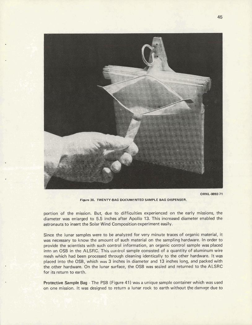
Figura 36. TWENTY-BAG DOCUMENTED SAMPLE BAO DISPENSER.
portion of the mission. But, due to difficulties experienced on the early missions, the diameter was enlarged to 5.5 inches after Apollo 13. This increased diameter enabled the astronauts to insert the Solar Wind Composition experiment easily.
Since the lunar samples were to be analyzed for very minute traces of organic material, it was necessary to know the amount of such material on the sampling hardware. In order to provide the scientists with such control information, an organic control sample was placed intn an OSB in the ALSRC. This cu~llrol sample consisted of a quantity of aluminum wire mesh which had been processed through cleaning identically to the other hardware. It was placed into the OSB, which was 3 inches in diameter and 13 inches long, and packed with the other hardware. On the lunar surface, the OSB was sesied and returned to the ALSRC for its return to earth.
Protective Sample Bag - The PSB (Figure 41) was a unique sample container which was used on one mission. It was designed to return a lunar rock to earth without the damage due to
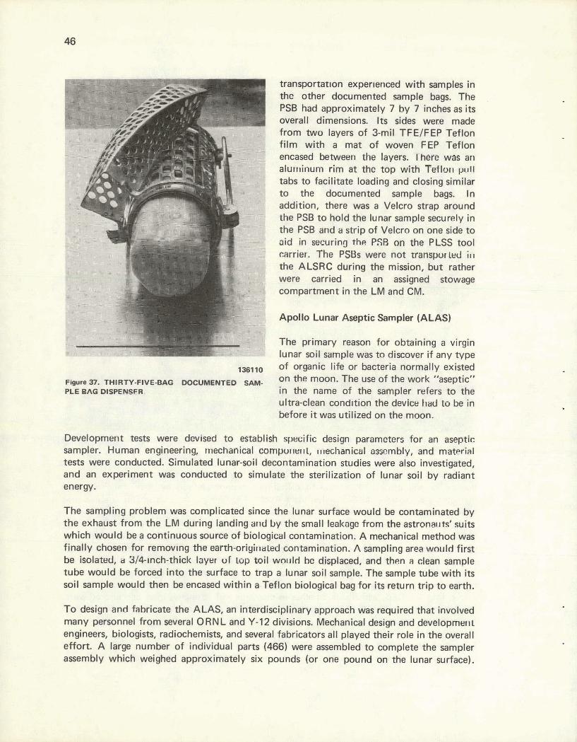
transportation exper~enced with samples in the other documented sample bag^. The PSB had approximately 7 by 7 inches overall dimensions. I t s sides wce
; as i ts made
from two layen of 3-mil TFE/FEP Teflon film with a mat of woven FEP Teflon encased between the layers. Them was an alun~inum rim at We top with Teflolri ~ ~ 1 i l
tabs to facilitate loading and closing similar to the documented sample bags. In addition, there was a Velcro strap around the PSB to hold the lunar stmple securely in the PSB and a strip of Velcro an one side to aid in =curing the ?.FB an the PLSS tool rarrier. The PSBs were not uarrspurbd in the ALSRC during the mission, but rather were carried in an assigned stowage compartment in the LM and CM.
Apollo Lunar Aseptic Sampler (ALAS)
I The primary reason for obtaining a virgin lunar soil sample was to discover if any type
,,,,, of organic life or bacteria normally existed
DOGUllYIEIYtED on the m n . The use of the work "aseptic" in the name of the sampler refers to the ultra-dean conditiari the dwiw hd to be in before it was utilized on the moon.
Development tests were devised to esmbllsh specific design parameters for an aseptic sampler. Human engineering, mechankal cornpur~e~~l, ~l.lechenical aswmbly, and material tests were conducted. Simulated lunar-soil decontamination studies were also investigated, and an experiment was conducted to simulate the sterilization of lunar soil by radiant energy.
The sampling problem was complicated since the lunar surface would be contaminated by the exhaust from the LM during landing and by the small leakage from the astrona~ts' suits which would be a continuous source of biological contamination. A mechanical method was finally chosen for removlng the earrh-oriyirrated contamination. A sampling area wcruld first be isolated, u B/+rnch-thick layer of top mil wolllrl bc displamd, and then a clean sample tube would be forced into the surface to trap a lunar soil sample. The sample tube with i t s soil sample would then be encased within a Teflon biological bag for i t s return trip to earth.
To design and fabricate the ALAS, an interdisciplinary approach was required that involved many personnel from several ORNL and Y-12 divisions. Mechanical design and developmw~l engineers, biologists, radiochemists, and several fabricators al l played their role in the overall effort. A large number of individual parts (466) were assembled to complete the sampler assembly which weighed approximately six pounds (or one pound on the lunar surface).
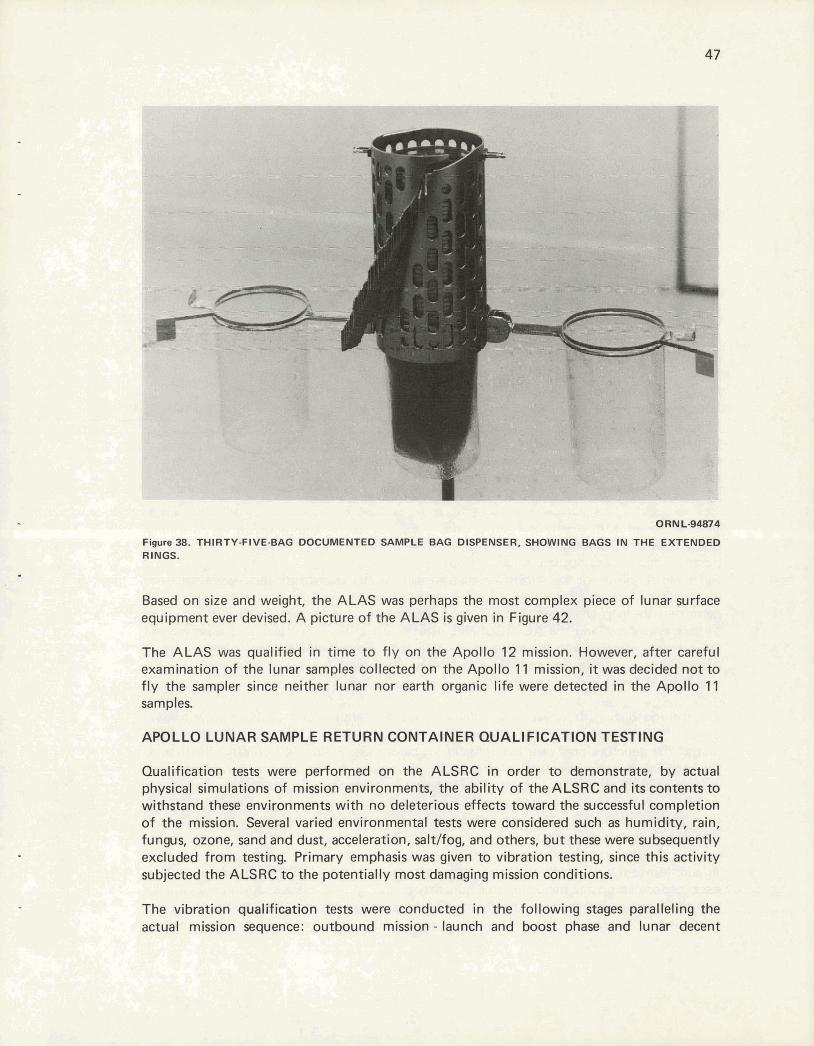
8 , ' ,-' 7; - < .... ,.4*.... , ... : a,, .,, . - .. , . ..
-. . - IN, ., . , . . , . -. . . . . . - - , . ' . . . . ; > . - 7 . - 6 . . n . , . . ,. : ;. i . -.. . , . . , ,:.;+ ., -,: - ( . . # , . . ~ ,,., ~ ~ . - - I-, ' . .: . - . .. .. 8 - 1. .>,y' -
8 ' , , ' . Based on size and weight, the ALAS was perhaps the most complex piece of lunar surface equipment ever devised. A picture of the ALAS is given in Figure 42.
The ALAS was qualified in time to fly on the Apollo 12 mission. However, after careful examination of the lunar samples collected on the Apollo 11 mission, it was decided not to fly the sampler since neither lunar nor earth organic life were detected in the Apollo 11 samples.
APOLLO LUNAR SAMPLE RETURN CONTAINER QUALIFICATION TESTING
Qualification tests were performed on the ALSRC in order to demonstrate, by actual physical simulations of mission environments, the ability of the ALSRC and its contents to withstand these environments with no deleterious effects toward the successful completion of the mission. Several varied environmental tests were considered such as humidity, rain, fungus, ozone, sand and dust, acceleration, saltlfog, and others, but these were subsequently excluded from testing. Primary emphasis was given to vibration testing, since this activity subjected the ALSRC to the potentially most damaging mission conditions.
The vibration qualification tests were conducted in the following stages paralteling the actual mission sequence: outbound mission - launch and boost phase and lunar decent

phase; inbound mission - lunar asent phase. Ead, segment of the vibration tests req,uir& that the ALSRC, mounted in a rnanmr simulat1~il:g the four-point SL~-spendon of the specwaft, $e su bjmed on emh of 'm three axes m zhe msptive Im&s of vibra$m plus a safety factor for bo* sinusoidal and randam spectra anticipated during the mission.
A Earge arnoom of the earty prqwlif itxition vihPSon and shock testing, a8 exemplified in Fikre 43, was-performed at th@ UCC-MD fd4$l$m: es W & p w * h ~ i ~ n d - m-m reZilu -mme
be%er defined, it hame elear that the limited Vibration equtpmt available vvas not adequate to s u d y all of the axial a&# "gvector" @quiremen@, The @sting wlrs then waMwmc4 to h N M d M S C vibra. tian faioilhy vrRSkh had. the needm4 dip rabk and real-time t'ahcbm gipea@urrt analysis equipment
lS?ll h order to simuk* c1-l~ the launch and filewe a. SOLAR H I I ~ ~WJOS~TIOI CONTAINER 8xmr sttuaWral I d m , o n the AESRC, an Bm.
inknal uaauum was m e d , since this was to be the cortclEtion of the ALSRC during actual missions. Designs for 4he ALSRC included m pmvlsion for wmrnal ewcwtion. A dosing fixture was designed and bail9 which pemWed the part-ially spen AQRE to be p l e d in o Iarw vacuum furnace, the vacuum furt- ~~~~, md the ALSRC sealed. ' F h w ~ ~ i, ALSRC wa_s sealed at rhe -re of the furnace, which as in the ran* of 1 x 10⁸ ton. Thir scheme for obtainingr internal w u r n was w r y e f i dve and was usuaUy combjrsed with a heating eyde similar to that which an ALSRC wowEd under* prior to mght
for routine testing, however, a quicker and eas'w methoel for ALSgC emquation was desired. To: amompltsh this easiel' rnestld, an muation tube was added to the qualif i ~ i o n unit at the puncture port nsar the right dbsjnq handle (see Figure 44). This modifiition to the A G R @ had no sXrw:ctura1 affect on the contabr, yet it allwed quick and easy ewge.wign wkh the added benefit of povUEgg a measure for helium leak &skins of the AGRC mcwm seals Continuous monitoring of the interm1 pressure of the ALSRC was thus fmsi$ZtrI men during the vilbrrr-Eion tests, by the comeaion of a thwmmuple vaewrn gap ta .&ie pumpdown port.
In UStion to the strwtural and vacuumtjntegri'ty tests an the ALSRC, many vibration tests were ~ r n r n s d on the m j c w internal contents of the ALSRC system. A primary concern uuw wawum, integrity of the inbound wnfigur9tion of the S E E and GASC inner mtainers. Numerous vibratian tests wee made with various oredible pwing

configurations of the inner containers with simulated lunar rocks. Again, it proved desirable to be able to effect a vacuum and measure the leak rate on the inner containers. One each of the GASC and SESC were modified with a 114-inch hole in the base of each of the containers to provide a helium-leak-check sample port. Large amounts of quantitative leak-rate data were thus obtained after subjecting the containers to lunar-ascent-phase vibration tests.
134105
F i r e 40. ORGANIC SAMPLE BAGS.
Another area of concern centered around the possibility that the ALSRC might leak to atmospheric pressure during earth lift off and remain in this condition until opened on the lunar surface. Tests were conducted to define the possible dangers, i f any, to the astronaut upon opening the ALSRC which had an approximate 16-psia internal pressure. It was determined that, upon the release of one of the two strap latches, the internal pressure would rapidly reduce to about 2 psia and the release of the second latch would harmlessly release the residual pressure.
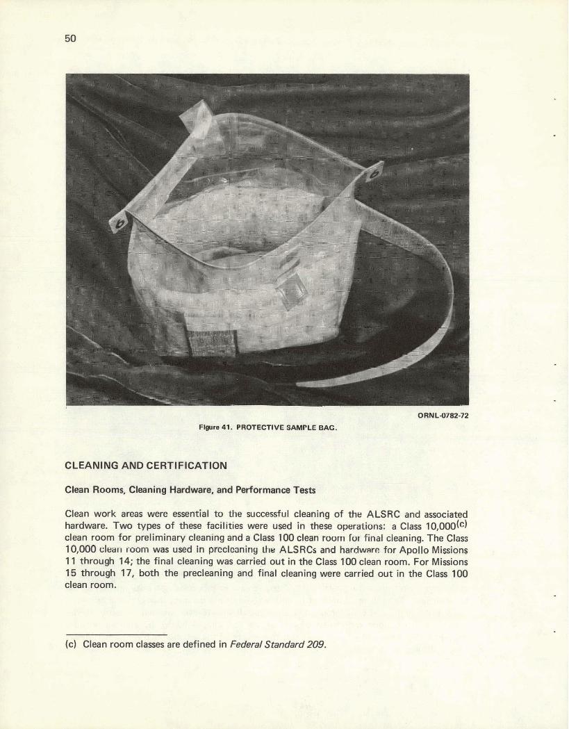
ORNL-82-72
Figure 41. PROTECTIVE SAMPLE BAG.
CLEANING AND CERTIFICATION
Clean Rooms, Cleaning Hardware, and Performance Tests
Clean work areas were essential t o the successful cleaning of the ALSRC and associated hardware. Two types of these facilities were used in these operations: a Class 10,000(~) clean room for preliminary cleaning and a Clam 100 clean room for final cleaning. The Class 10,000 clein room was used in prcolmniny Lhe ALSRCs and hardware for Apollo Missions 11 through 14; the final cleaning was carried out in the Class 100 clean room. For Missions 15 through 17, both the precleaning and final cleaning were carried out in the Class 100 clean room.
(c) Clean room classes are defined in Federal Standard 209.

The Class 10,000 horizontal-air-flow clean room, illustrated in Figure 45, was constructed from wood framing covered with sheet plastic. A high-efficiency particulate air (HEPA) filter system provided the air supply and recirculation. Two inner areas (a cleaning area and a bag fabrication area) constructed similar to the outer room were also supplied with HEPA filtered air. The entire area was operated at a slight positive pressure, but no precise control of temperature or humidity was attempted.
129950
Figure 42. AWLLO LUNAR ASEPTIC SAMPLER.
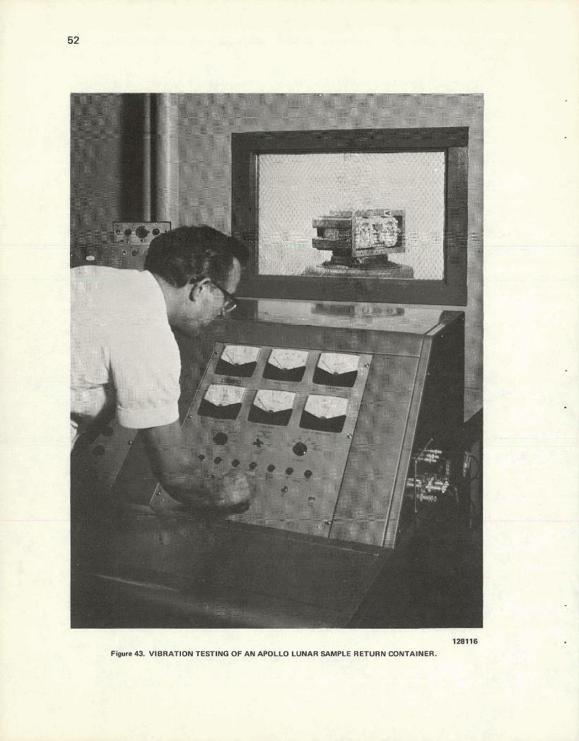
Figure 43. VIBRATION TESTING OF AN APOLLO LUNAR SAMPLE RETURN CONTAINER.

Figure 44. FRONT VtEW OF AN APOLLO LUNAR SAMPLE RETURN CONTAINER SHOWING THE PUMPDOWN TUBE.
Two of the major equipment items in the Class 10,000 inner cleaning area were: (1) cleaning tanks equipped with ultrasonic agitation, and (2) an inspection table provided with an ultraviolet light. Filtered air was swept across the three cleaning tanks and inspection table before exiting through the opposite wall. The cleaning tanks contained deionized water, specially purified trichlorotrifluoroethane, and nanograde isopropyl alcohol.
All the clconing tanks were constructed af stainless steel and the associated plumbing of aluminum or Teflon. The general operation of this facility and the hardware handling procedures were very important for attaining the microgram-per-square-centimeter cleaning required to obtain the ultimate degree of hardware cleanliness.
A Class 100, vertical laminar flow (VLF) clean room, illustrated in Figure 46, was used for the final cleaning.
Supply air, filtered through two prefilters and two banks of HEPA filters, was supplied through the room ceiling, discharged through a metal-grated floor (containing roughing filters), and returned through cavity walls on two sides of the room. The HEPA filters were specially selected because of their 99.99 percent efficiency. As indicated in Figure 47, solvent vapor adsorption (benzene and isopropyl alcohol) was accomplished in the recirculated air by activated charcoal filters installed between the recirculating fan and the initial bank of HFPA filters.
Table u
I Table
Cleaning Tanks A - Deionized Water B - Trichlomtrifluatmthane C - loopropyl Alcohol
i?
1 Air Samplers
- Mernbnne Fllter
a\ - Membrane Filter
- Membrane Filter
LEGEND
Receiving and Shipping Area
A Vacuum Drying Chamber
Level 11 Cleaning ,,
(41 - Automatic Particle Counter
onditjoning K j
Elgure 46. A CLASS 10P00 CLEANING AREA.
' 1
Air velocity in the room was approximately 93 feet per minute and resulted in a total supply of 35,000 cubic feet per minute, of which 2,300 cubic feet per minute escaped through the air lock. There were over 600 air changes in the room per hour. Both tempratilre and humidity r~n t ro l were mair~taincd at 21 f. U.60 C and 50 percent relative humidity.
The equipment in this particular clean room consisted of six cleaning tanks (30" x 30" x 24" with a working capacity of 20 gats), a bagsealing apparatus, and an inspection and packaging table. All cleaning tanks, the hoist and monorail, and associated piping were constructed of stainless steel. The tanks contained deionized water, pure trichlorotrifluoroethane, and nanograde isopropyl alcohol-benzene solutions. A photograph of the Class 100 VLF clean room with cleaning tanks is provided in Figure 48.
Transfer
Sealing Apparatus
Cleaning Tanks
21' 3" F - Certification Tank - IPA-Benzene
S 0 l ~ t l t D a m s 1 - Clem PCA 2 - Clean Deionized Water 3 - Uasd PCA 4 - Used IPA-Benzene
Parts Pas Through
F i r r e 46. A CLASS 100 CLEANING LABORATORY.
31,100 c fm
I - -
I Charcoal Filter
hilled Water Coil
Filter
'Floor Grating
Figure 47. A CLASS 100 CLEANING LABORATORY ARRANGEMENT OF MECHANICAL EQUIPMENT AND AIR DISTRIBUTION.
a. A CLASS 180 VERTICAL-FLOVII GLEAN ROOM, SHQWlNO W E ClEAMlNQ TANKS.
The ALSRC presented two major problems during cleaning. First, its size and delicacy demanded a special method of handling within the cleaning tanks and during transfer between tanks. A special fixture was developed which held the ALSRC will1 the lid partially opened and allowed rotation of the box within the tank at one revolution per minute. This fixture also allowed the ALSRC to be hoisted and moved between tanks on a rr~onorail, Second, the thermocouple gauge on the ALSRC also presented a problem in cleaning. The gauge, being constructed from 3-mil wire, was susceptible to oscillation by the ultrasonic agitation. To remove this problem, the power level of the ultrasonic agitation was adjusted to obtain the desired cleaning level without harming the thermocouple gauge.
Air-How Tests - In order to determine the air-flow characteristics over and in rhe vicinity of the cleaning tanks, Dry Ice was placed in one of the tanks along with warm water. The dense fog that was produced overflowed the tank and was swept by the laminar-flow air stream directly to the floor return alr system. A photograph rnade during this 1-1 is presented in Figure 49. -
_ ' I ;, .g :, l$,.;,:t+-~)h4 - ,? .-<A Benzene Concentration Tests - The use of benzene as one of the solvents in the cleaning operation introduced both a fire and health hazard. To determine the actual benzene concentrations in the room, routine tests were conducted at the breathing-zone level, and special tests were made of the solvent concentration levels in the area above and below the benzene-isopropyl alcohol tanks. Routine tests conducted under normal working conditions have indicated benzene concentrations in the breathing zone of three parts per million or
133840
Figure 49. AIR-FLOW CHARACTERISTICS IN A CLASS 100 LAMINAR-FLOW CLEAN ROOM.
less which are well below the threshold level value (TLV) of 25 parts per million.(d)
Special benzene determinations were made by a survey of the air in the room from east to west at three different elevations. Air samples were taken by the use of evacuated bottles at the following elevations: (1) six inches above the floor, (2) Wo inches above the top of the benzeneisopropyl alcohol cleaning tanks, and (3) six feet above the floor. The samples were analyzed by the uee of a gas chromatograph. Benzene concentration levels for the three elevations and extending from the east-to-west walls are shown by the graph of Figure 50. The curves indicate excellent control of solvent fumes in this particular clean room. The high concentration of benzene in the vicinity of the tanks, compared with the low concentration in the breathing zone, demonstrates the efficiency of the solvent removal system.
Certification of the Particulate Count in the Final Cleaning Area
Initial checkout ot the Class 100 clean room ~ndlcated a cleanltness level of one particle (0.3 micrometer in size or larger) for each three cubic feet of air sampled in a test extending for over 400 hours.
Particulate counts were continuously monitored by the use of an automatic particle counter. These test results showed no degradation of the room's cleanliness from the initial startup of the facility through the ALSRC program, a period of over seven years. Particle counts made at four locations in the room showed zero particulate count in the 0.5 micrometer site and larger.
Cleaning the ALSRC and Associated Hardware
In order to obtain maximum knowledge from lunar samples taken on the Apollo missions, it was necessary to develop special cleaning procedures for the ALSRC and associated hardware. It was mandatory that surface contamination be removed from all surfaces of the ALSRC and equipment, with specific emphasis placed on the removal of organic contaminants. Since the post-flight analysis could detect one part per billion of organic material in a lunar sample, it was necessary to clean the ALSRC and equipment to a cleanliness of 10 nanograms (10-8 gram) or less per square centimeter of surface area.
A very stringent cleaning operation was developed, as outlined in Figure 51. Polishing compounds, machining and dust contamination, and contamination from personnel handling required precleaning in order not to overload the final cleaning operation. In addition, it was necessary that the precleaning and final cleaning operations not contribute to corrosion of the components which might change the properties of the hardware and cause operational failure.
- (d) Contamination Control Handbook, NASA SP-5076, pp 11 1-1 77.
(el Little, J. C. and Choat, E. E.; "Significant Parameters of Clean Room Design", 1965 Proceedings; 45th Annual Technical Meeting of the AACC.
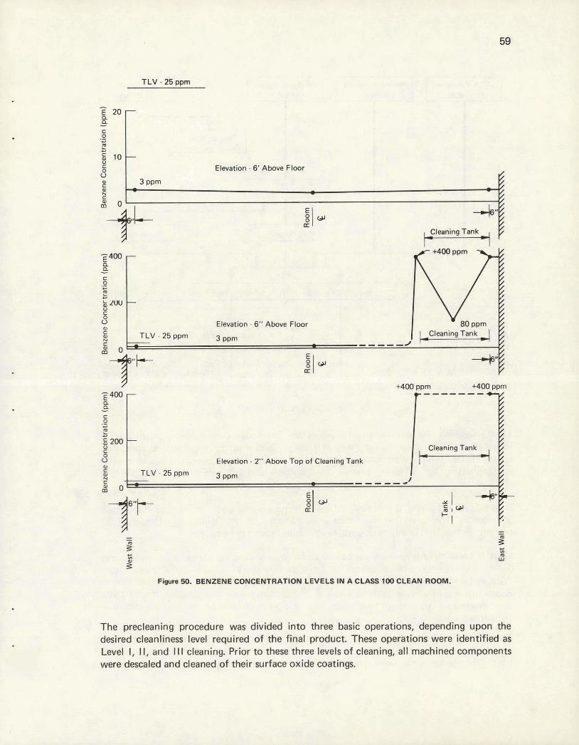
TLV - 25 wrn
L. C
g 1 0 -
8 U P) C
A
The precleaning procedure was divided into three basic operations, depending upon the desired cleanliness level required o f the final product. These operations were identified as Level I, II, and Ill cleaning. Prior t o these three levels o f cleaning, all machined components were descaled and cleaned of their surface oxide coatings.
Elevation - 6' Above Floor
3 PPm - - - -
p 4 0 0 P P - C 0 .- C
2 C
$ Z W 0 C
8 0) c A
a
-
-
Elevation - 6" Above Floor TLV - 25 ppm 3 PPm - -
+4w PPrn +400 Ppm 400 -------
P P - C 0 .- C
E C
g200 8 U 0 C
A c
-
Elevat~on - 2" Above Top of Cleaning Tank TLV - 25 ppm 3 PPm
i2 0 -
- - - - P s 5 P
LU 3
Figure 50. BENZENE CONCENTRATION LEVELS IN A CLASS 100 CLEAN ROOM.
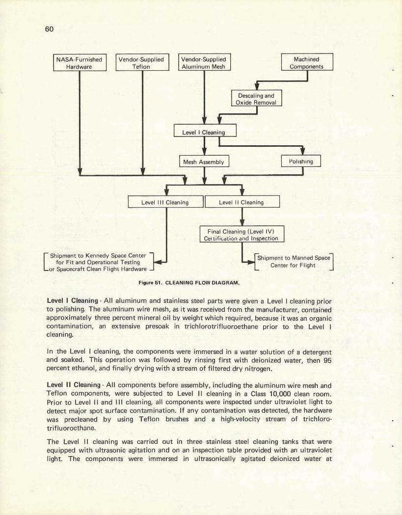
Figure 61. CLEANING FLOW DIAGRAM.
Level I Cleaning - All aluminum and stainless steel parts were given a Level I cleaning prior to polishing. The aluminum wire mesh, as it was received from the manufacturer, contained approximately three percent mineral oil by weight which required, because it was an organic contamination, an extensive presoak in trichlorotrifluoroethane prior to the Level I cleaning.
Machined Components
In the Level I cleaning, the components were immersed in a water solution of a detergent and soaked. This operation was followed by rinsing first with deionized water, then 95 percent ethanol, and finally drying with a stream of filtered dry nitrogen.
* I Descaling and
Oxide Removal
I t
Level I Cleaning
I t
Mesh Assembly Pollsh~ng
I v 9 t
I J. I
- Level I I I Cleaning I I Level 1 1 Cleaning I -
Final Cleaning (Level IV) GI ~ificcrtion and Inspection
Shipment to Kennedy Space Center - Shipment to Manned Space
for Fit and Operational Testing or Spaamaft Clean Flight Hardware
Center for Flight I
Vendor-Supplied Aluminum Mesh
NASA-Furnished Hardware A
Level I 1 Cleaning - All components before assembly, including the aluminum wire mesh and Teflon components, were subjected to Level 11 cleaning in a Class 10,000 clean room. Prior to Level II and I II cleaning, all components were inspected under ultraviolet light to detect major spot surface contamination. If any contarnbation was detected, the hardware was precleaned by using Teflon brushes and a high-velocity stream of trichloro- trif luorocthane.
I Vendor-Supplied Teflon
The Level II cleaning was carried out in three stainless steel cleaning tanks that were equipped with ultrasonic agitation and on an inspection table provided with an ultraviolet light. The components were immersed in ultrasonically agitated deionized water a t
43 - 490 C for 20 minutes, rinsed with fresh deionized water, and drained. The components were then immersed in ultrasonically agitated nanograde isopropyl alcohol for 20 minutes, followed by immersion in precision cleaning agent (PCA)-grade ultrasonically agitated trichlorotrifluoroethane at room temperature for 20 minutes. They were then dried with filtered dry nitrogen.
Following the solvent cleaning, the parts were inspected using ultraviolet light to detect any dirt particles or lint. If any uncleaned spots or lint were found, the components were returned to Level II cleaning. The components were placed in prefabricated Teflon bags which were also cleaned by the Level I I procedure.
Solvents used for precleaning were discarded after the surface area-to-solvent ratio of 25,000 cm2 per garlon for each bath had been reached.
Level Ill Cleaning - Items cleaned to Level I I I were cleaned using deionized water, but were immersed in the ultrasonically agitated trichlorotrifluoroethane for only 10 minutes and then dried.
All components which were sent to the Kennedy Space Center (NASA-KSC) for a f i t check to the spacecraft, crew familiarization, or stowage in the spacecraft for flight were given Level I I I cleaning. Those components returned from the NASA-KSC were subjected to Level I II cleaning before final cleaning for stowage in the ALSRC.
Final Cleaning - Level IV - Level IV cleaning was carried out in the Class 100 VLF clean room. Hardware cleaned to Level I I was handled in the final cleaning area with Teflon gloves and stainless steel tools. Personnel in the final cleaning area wore surgical face masks and monofilament nylon suits, as noted in Figure 52. Ear protection from ultrasonic noise and eye protection against ultraviolet light were provided for each employee. The operators wore surgical gloves underneath the Teflon gloves in order to retain body oils. Hardware that had been Level I I cleaned and packaged was moved into the clean room area through a special pass-through window, unpacked, weighed, and given an additional ultraviolet inspection (Figure 53).
In the first tank, the hardware was immersed in ultrasonically agitated deionized water (1.5 pmho at 240 C) at 43 - 490 C for 20 minutes. The hardware was then transferred to the second tank containing an ultrasonically agitated 3:1 benzene-isopropyl alcohol mixture (nanogram purity) for 20 minutes. After this bath, the hardware was immersed in the third tank containing ultrasonically agitated PCA-grade trichlorotrifluoroethane for 20 minutes. It was then immersed in a fourth tank containing a fresh 3:1 benzene-isopropyl alcohol mixture and ultrasonically agitated tor 20 minutes. Finally, the hardware was immersed in the certification tank containing a 3:1 benzene-isopropyl alcohol mixture, where it was ultrasonically agitated for 10 minutes. The hardware from the certification tank was transferred to a clean, stainless steel table using clean, stainless steel tools and allowed to dry in air.
Solvents used for final cleaning and certification were discarded after enough components were cleaned to equal a surface area-to-solvent ratio of 25,000 cm2 per gallon for each bath,

and after a sample had been removed for certification. After each solvent change, the tanks were rinsed w i th fresh solvent.
f- m. PIE-lWDNHEL 119 THE FIMAL CCEANlRtQ AREA. (Lml IY) -.-- -- - - - - -. - - --- -
Special Cleaning of Laminated Teflon Fabric
The woven Teflon cloth used in the fabrication of the new sample collection bags was available f rom the manufacturer in two forms: "natural" and "bleached". The natural t ab r~c was brown and was the direct producr of their manufactuririy proms; 111e bleaclrecl fabric was white, resulting f rom a bleaching step with 95 percent sulfuric acid and 5 percent nitr ic acid a t approximately 316O C. The Teflon thread used in sewing the bags WZIS available only i n the natural form. Attempts t o certify the required cleanliness level after the cleaning sequences just outlined either failed o r were much too close t o the allowable maximum. For this reason, steps were taken t o isolate the inherent contamination i n the Teflon fabric and thread used.
Gravimetric analyses of "natural" Teflon fabric and thread by leaching wi th a 95 percent sulfuric acid-5 percent nitr ic acid mixture at 3160 C for one hour showed a total o f 3.8 percent materials other than Teflon. Infrared spectrophotometric analyses of the material leached f rom samples of fabric and thread samples with water, trichlorotrifluoroethane,
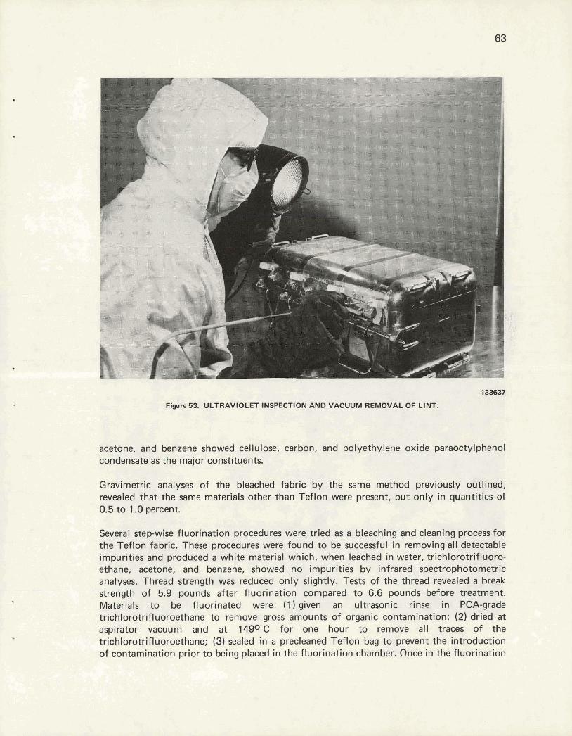
1smm
Fwre 5% UULTRAWIOLETI#gPEC7ION AlWD VACUUM REMbVAC OF LINT.
acetone, and benzene showed cellulose, carbon, and polyethylene oxide paraoctylphenol condensate as the major constituents.
Gravimetric analyses of the bleached fabric by the same method previously outlined, revealed that the same materials other than Teflon were present, but only in quantities of 0.5 to 1.0 percent.
Several stepwise fluorination procedures were tried as a bleaching and cleaning process for the Teflon fabric. These procedures were found to be successful in removing all detectable impurities and produced a white material which, when leached in water, trichloratrifluoro- ethane, acetone, and benzene, showed no impurities by infrared spectrophotometric analyses. Thread strength was reduced only slightly. Tests of the thread revealed a break strength of 5.9 pounds after fluorination compared to 6.6 pounds before treatment. Materials to be fluorinated were: (1)given an ultrasonic rinse in PCA-grade trichlorotrifluoroethane to remove gross amounts of organic contamination; (2) dried a t aspirator vacuum and a t 14g0 C for one hour to remove all traces of the trichlorotrifluoroethane; (3) sealed in a precleaned Teflon bag to prevent the introduction of contamination prior to being placed in the fluorination chamber. Once in the fluorination
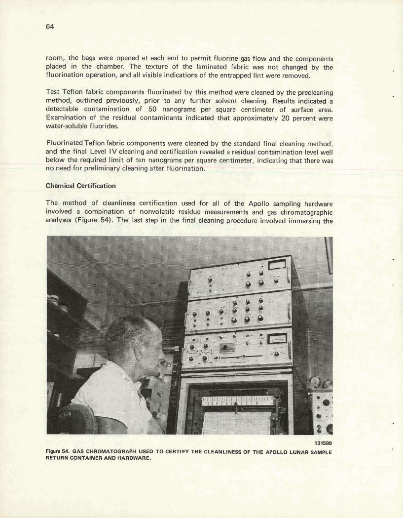
room, the bags were opened a t each end t o permit fluorine gas f low and the components placed in the chamber. The texture of the laminated fabric was not changed by the fluorination operation, and all visible indications of the entrapped l int were removed.
Test Teflon fabric components fluorinated b y this method were cleaned by the precleaning method, outlined previously, prior t o any further solvent cleaning. Results indicated a detectable contamination of 50 nanograms per square centimeter o f surface area. Examination of the residual c0ntaminan.t~ indicated that approximately 20 percent were water-soluble fluorides.
Fluorinated Teflon fabric components were cleaned by the standard final cleaning method, and the final Level I V cleaning and certification revealed a residual contamination level well below the required l imi t o f ten nanograms per square centimeter, indicating that there was no need for preliminary cleaning after tluor~nation.
Chemical Certification
The method o f cleanliness certification used for all o f the Apollo sampling hardware involved a combination o f nonvolatile residue measurements and gas chromatographic analyses (Figure 54). The last step in the final cleaning procedure involved immersing the
Fiym 64. GAS CHROMATOGRAPH USED TO CERTIFY THE CLEANLINESS OF THE APOLLO LUNAR SAMPLE RETURN CONTAINER AND HARDWARE.
hardware in a certification bath and subsequent agitation. A one-gallon sample of the certification mixture was collected both before and after immersion of the hardware. These samples were then evaporated at 38O C under a reduced pressure until the residue weights were constant The residue from each sample was then weighed to an accuracy of k 0.05 milligram. Knowing the solvent-to-surface area ratio of the certification bath, and assuming that the change in the nonvolatile residue weight after immersion of the hardware was due to hardware contamination, it was possible to calculate the residual contamination on the hardware surface from the difference between the two residue weights. These residues were then redissolved in two cubic centimeters of nanograde benzene, and a ten-microliter sample of these solutions was injected into a gas chromatograph programmed between 100 and 2500 C. Using a blank of decane treated in the same manner and the assumption used before, the areas under the two sample curves could be used to calculate the residual contamination. It should be noted that these methods of certification are used primarily because of their similarity to the methods used for the analyses of the lunar material for organics.
Using this sampling procedure and analyses, all the Level IV-cleaned ALSRCs and hardware for Missions 12 through 17 were c ~ r t i f i ~ d tea c~ntain less than ten nanograms of residue per square centimeter of surface area. The cleanliness specification of less than ten nanograms of residue per square centimeter of surface area was required only after the Apollo 1 1 mission.
Physical Certification
After final cleaning of the ALSRC and associated hardware, it was necessary to certify the operation of the many moving parts and perform certain physical tests to be assured of meeting the required specifications.
It became apparent that excessive force was necessary to operate the strap-latch mechanism on the ALSRC. In order to reduce the force for this operation, contact surfaces of the mechanism between the toggle latch handle and the ALSRC body were burnished with molybdenum disulfide (MoS2) powder. These surfaces were burnished until the strap latches closed with a force not exceeding 20 inch pounds in the inbound configuration.
After the ALSRC was packed with a l l flight hardware and strap latches closed, the thermocouple wire was checked for continuity. The ALSRC was inspected under ultraviolet light for visible contamination, placed into two clean Teflon bags, and moved to the radiation monitor station.
DETECTION OF RADIOACTIVE NUCLIDES ON THE ALSRC AND ASSOCIATED HARDWARE
Principal Purpose
One of the major interests in the lunar material was to determine the levels of radium, thorium, and potassium, the most common naturally occurring radioactive nuclides in the earth's soil. To aid in this, it was required that all components of the hardware which could come in contact with the lunar material be fabricated from essentially radioactively free material. Additionally, care was to be taken to prevent contamination during fabrication, since the ALSRC was to be manufactured in a uranium processing plant.

To assure that the ALSRC contained a minimum of the elements of interest, most stock materials and all finished components were measured for radioactivity, sometimes separately, and always as a complete package just prior to shipment.
Measurement Technique
Low-level radioactivity measurements required three components: (1) a shield to reduce the background radioactivity, (2) a detector to collect the radiation emitted from the samples being monitored, and (3) the necessary electronics to receive the pulses of energy from the detector, then sort, count, and store them by energy.
Shield - In order to reduce the background radiation to acceptable levels, several inches of lead and/or steel were required. Figure 55 shows a shielded room constructed of 114-inch sheets of steel laminated to a wall thickness of eight inches, with a partial liner of tungsten powder-loaded epoxy tile. This system will accommodate samples as large as a threefoot cube. In order to increase the sensitivity and to reduce background radia- tion further, a second system consisting of a two-inch shield of lead was constructed in- side the steel room (Figure 56). Additional- ly, the detector surfaces not incident on the sample being measured were shielded with 112 inch of tungsten (Figure 57).
Detectors - Detectors of thallium-activated sodium iodide were used for these measure- ments. The detectors were nine inches in diameter by four inches thick. These large detectors assured good geometry and counting efficiency, which reduced the minimum level of detectable radioactivity. 148347
Fiwre 55. SHIELDED ROOM CONSTRUCTION. SHOW-
Electronics - Two pulse-height multichannel ~ N : ~ I ~ ~ ~ o ~ WLE REmRN am-
analyzers (Figure 58) were used to analyze the pulses of electrons. At the end of a preset time, the number of pulses of each energy ran@ were displayed ill the form of a histograni. Such a histogram is presented in Figure 59 and shows the number of events occurring for each 7.75-Kev energy band from 0 to 3.2 Mev. This histogram (spectrum) is an 800-minute count of background radiation inside the shielded room.
Data Analysis
After a spectrum was collected, some type of analysis had to be performed. This operation could be as simple as examining the spectrum and noting the concentration of counts
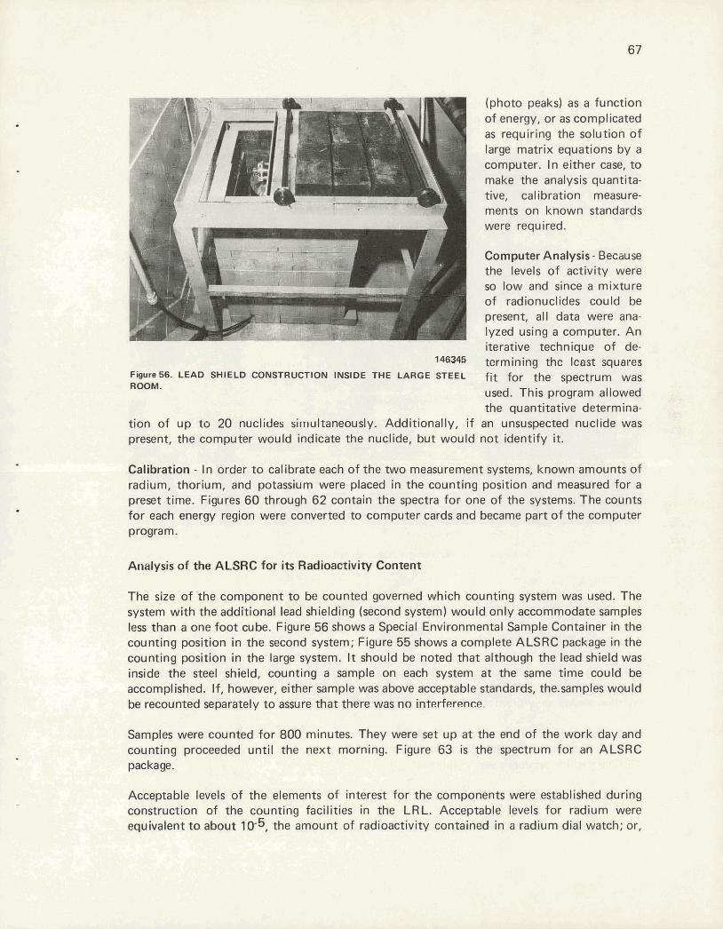
of energy, or as complicated as requiring the solution of large matrix equations by a computer. In either cast to make the analysis quantita- tive, cal ilaration measure- ments on known standards were required.
Computer Analysis - Because the levels of activity were so low and since a mixture of radionuclides could be present, all data were ana- lyzed using a computer. An iterative technique of de-
. termining tke least wuares Figure 56. LEAD SHIELD CONSTRUCTION INSIDE THE LARGE STEEL fit .for the spmtrum was ROOM. used, This program allowed
the quantitative determina- tion of up to 20 nuclides simultaneawsl~y. Additionally, if an unsuspected nuclide was present, the computer would indicate the nuclide, but would not identify it.
Calibration - In order to calibrate each of the Wo measurement systemsi known amounts of radium, thorium, and potassium were placed in the counting position and measured for a preset time. Figures 60 through 62 contain the spectra for one of the systems. The counts for each energy region were converted to computer cards and became part of the computer program.
Analysis of the ALSRC for i ts Radioactivity Content
The size of the component to be counted governed which counting system was used. The system with the additional lead shielding (second system) would only zw5ommodate samples less than a one foot cube. Figure 56 shows a Special Environmental Sample Container in the counting position in the second system; Figure 55 shows a camplete ALSiRG package in the counting position in the large system. It should be noted that although the lead shidd was inside the steel shield, counting a sample on each system at the same time could be accomplished. If, however, eiffier sample was above acceptable standards, the.samples wwou Id be recounted separately to assure that there was no interfw~nce.
Samples were counted for 800 minutes. They were set up at the end of the work day and counting proceeded until the next morning. Figure 63 is the spectrum for an ALSRC package.
Acceptable levels of the elements of interest for the components were established during construction of the counting facilities in the LRL. Acceptable levels for radium were equivalent to about 10-5, the amount of radioactivity contained in a radium dial watch; or,

on a weight basis, about one part per quarIrillion (1015). Acceptable activity leveis for thorium and potassium were equally small.
146348
F i r e 57. TUNGSTEN SHIELD AROUND THE DETECTOR.
USE OF THE ALSRC HARDWARE
Pmftp~ration Prior to a Mission
Following the fabrication, testing, cleaning, and certification of the ALSRC hardware, the appropriate items for each mission were prepared for flight. This preflight preparation entailed several activities both at the Y-12 Plant and at the LRL.
At Y-12, activities ~onsisted primarily of packing the required hardware into the appropriate ALSRC. Figures 64 through 75 illustrate the sequential packing of one ALSRC for Apollo 16. The packing sequence was as follows:
1. ALSRC with the OCS (Figure 64).
2. Add SCB with two drive tubes and the CSVC (Figure 65).
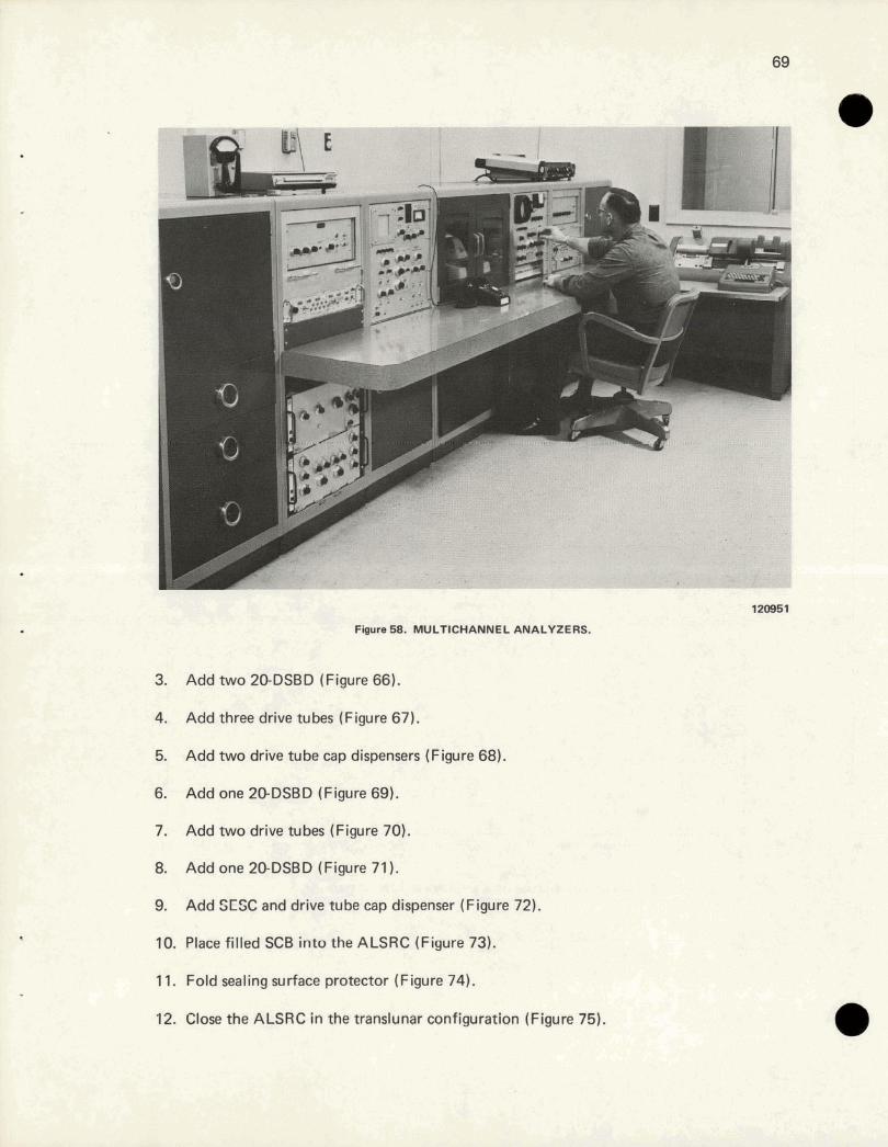
3. Add two 20-DSBD (Figure 66).
4. Add three drive tubes (Figure 67).
5. Add two drive tube cap dispensers (Figure 68).
6. Addone20-DSBD (Figure69).
7. Add two drive tubes (Figure 70).
8. Add one 20-DSBD (Figure 71 ).
9. Add SESC and drive tube cap dispenser (Figure 72).
10. Place filled SCB into the ALSRC (Figure 73).
11. Fold sealing surface protector (Figure 74).
12. Close the ALSRC in the translunar configuration (Figure 75).
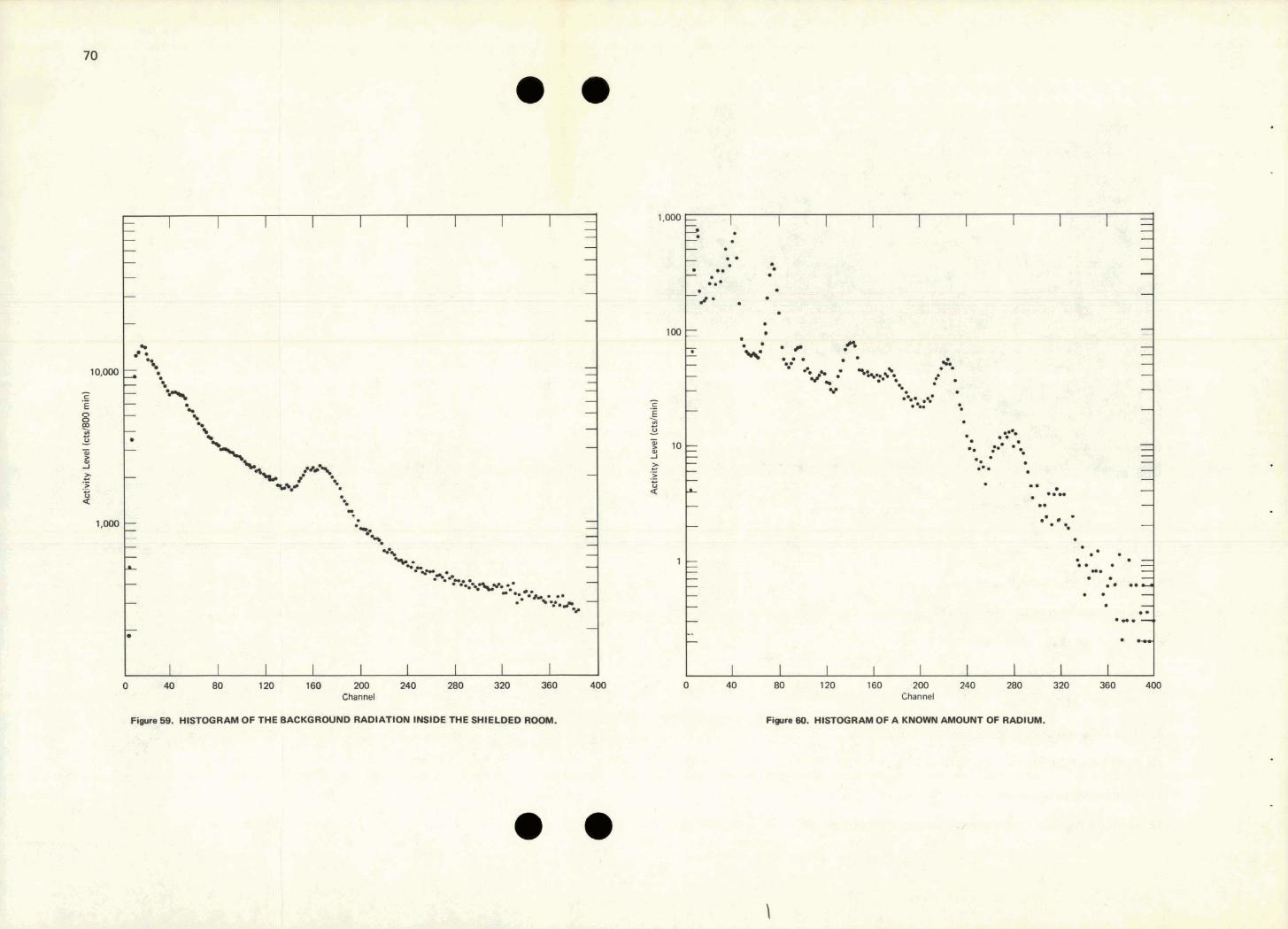
0 40 80 120 160 200 240 280 320 360 400 Channel
I I 1 I 1 I I I I 0 40 80 120 1 60 200 240 280 320 360 400
Channel
Fi- 80. HISTOGRAM OF A KNOWN AMOUNT OF RADIW, ,z tl*?
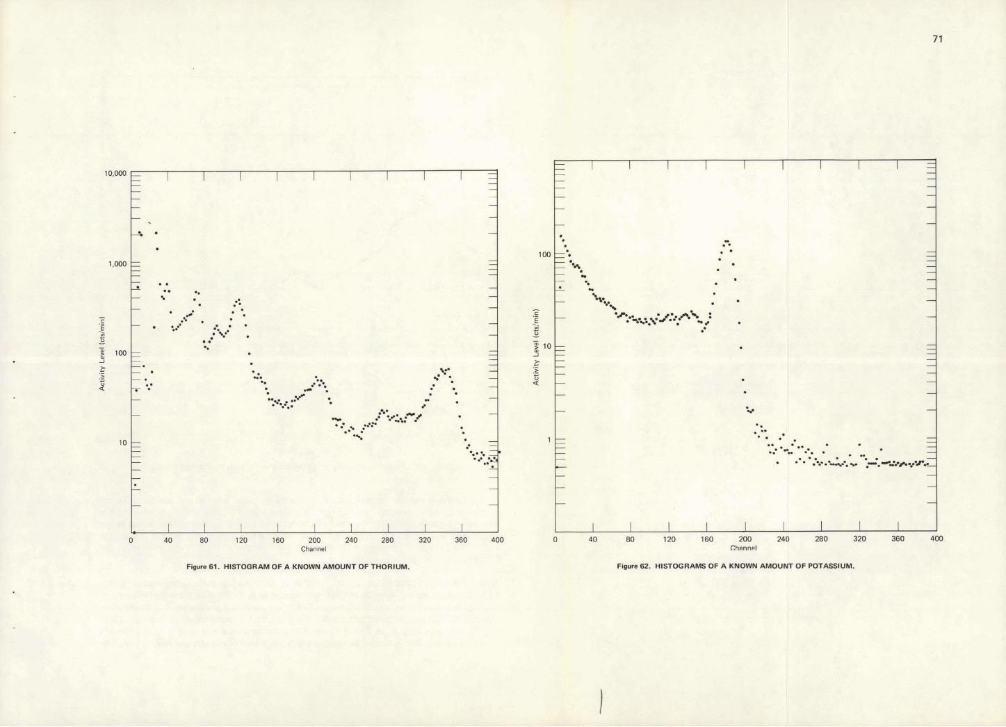
Act
ivity
Lev
el Ic
tslm
in)
Act
ivity
Lev
el (c
tslm
in)
- 4
A
o
8
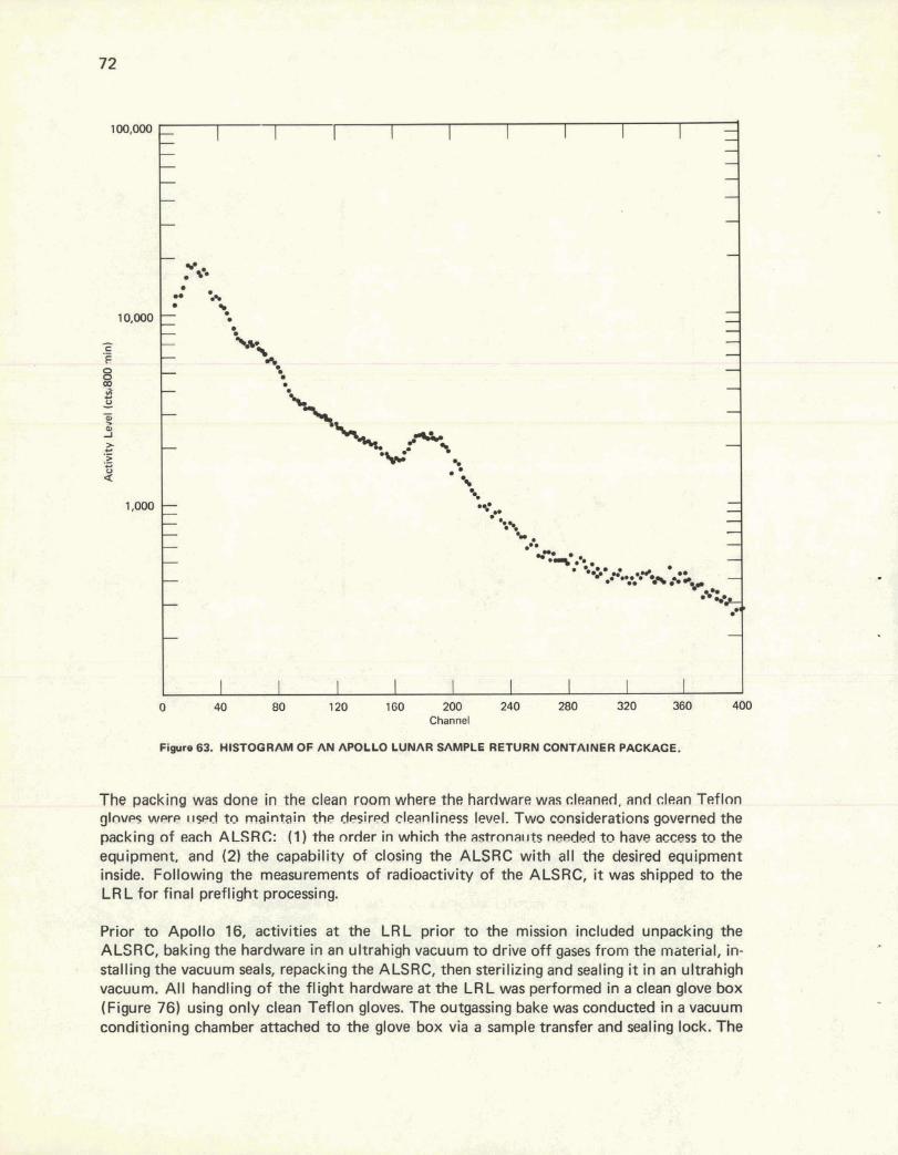
Figura 63. HISTOGRAM OF AN APOLLO LUNAR SAMPLE RETURN CQNTAINER PACKAGE.
The packing was done in the cban room where the hardware was clsansd, and clean Teflon gloves were ~.rslzd t o maintain the desired cleanliness level. Two considerations ~ v e m e d the packing o f e ~ c h ALSRC: (1) the order in which the astronauts needed to have access to the equipment. and (2) the capability of closing the ALSRC with all the desired equipment inside. Following the measurements of radioactivity of the ALSRC, it was shipped to the LR L for final preflight processing.
Prior to Apollo 16, activities at the LRL prior to the mission included unpacking the ALSRC, baking the hardware in an ultrahigh vacuum to drive off gases from the material, in- stalling the vacuum seals, repacking the ALSRC, then sterilizing and sealing it in an ultrahigh vacuum. Al l handling o f the flight hardware at the LRL was performed in a clean glove box (Figure 76) using only clean Teflon gloves. The outgassing bake was conducted in a vacuum conditioning chamber attached t o the glove box via a sample transfer and sealing lock. The
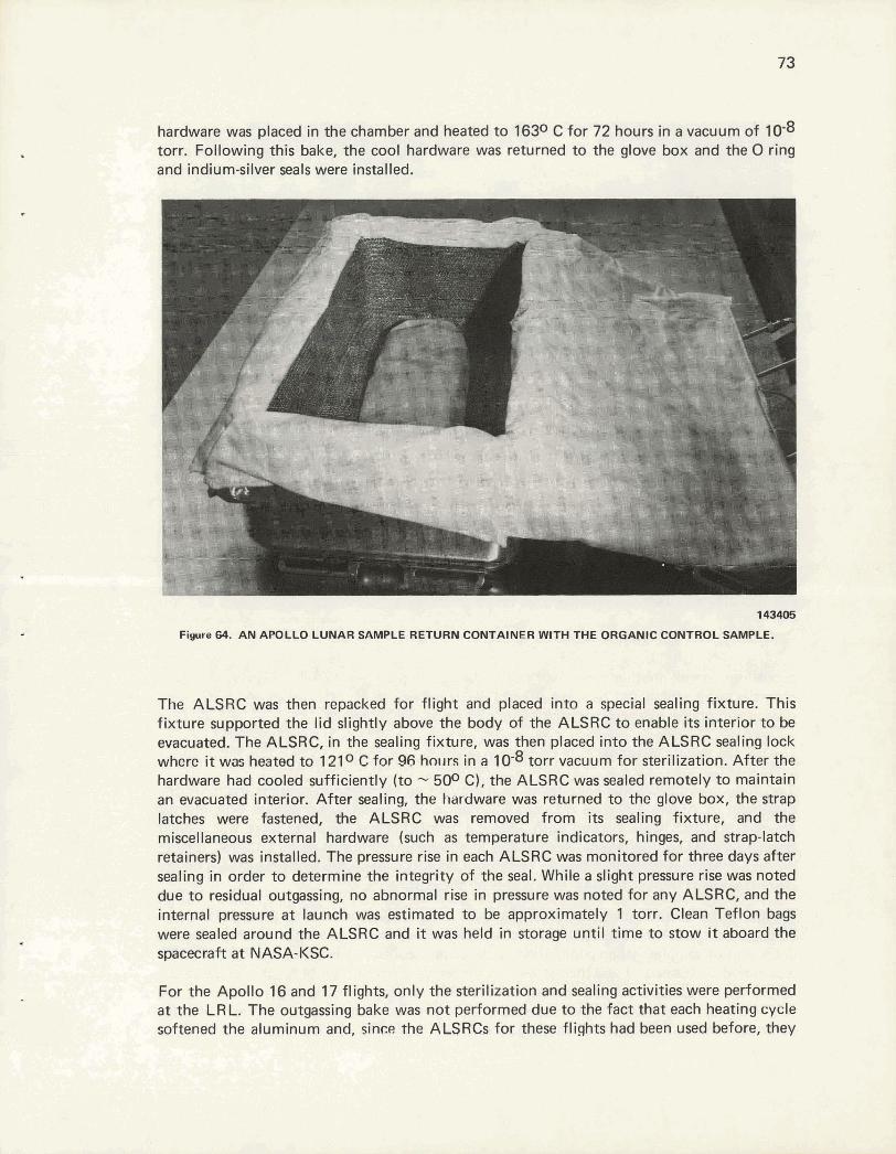
hardware was placed in the chamber and heated to 1630 C for 72 hours in a vacuum of 10-8 torr. Following this bake, the cool hardware was returned to the glove box and the 0 ring and indium-silver seals were installed.
143405
F i r e 64. AN APOLLO LUNAR SAMPLE RETURN CONTAINER WITH THE ORGANIC CONTROL SAMPLE.
The ALSRC was then repacked for flight and placed into a special sealing fixture. This fixture supported the lid slightly above the body of the ALSRC to enable i t s interior to be evacuated. The ALSRC, in the sealing fixture, was then placed into the ALSRC sealing lock whcrc it was heated to 1210 C for 96 hcr~rrs in a 10-8 tarr vacuum for sterilization. After the hardware had cooled sufficiently (to - 500 C), the ALSRC was sealed remotely to maintain an evacuated interior. After sealing, the hardware was returned to the glove box, the strap latches were fastened, the ALSRC was removed from its sealing fixture, and the miscellaneous external hardware (such as temperature indicators, hinges, and strap-latch retainers) was installed. The pressure rise in each ALSRC was monitored for three days after sealing in order to determine the integrity of the seal. While a slight pressure rise was noted due to residual outgassing, no abnormal rise in pressure was noted for any ALSRC, and the internal pressure at launch was estimated to be approximately 1 torr. Clean Teflon bags were sealed around the ALSRC and it was held in storage until time to stow it aboard the spacecraft a t NASA-KSC.
For the Apollo 16 and 17 flights, only the sterilization and sealing activities were performed at the LRL. The outgassing bake was not performed due to the fact that each heating cycle softened the aluminum and, since the ALSRCs for these flights had been used before, they
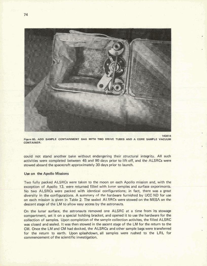
143414 Fiwre 65. ADD SAMPLE CONTAINMENT BAG WITH TWO DRIVE TUBES AND A CORE SAMPLE VACUUM CONTAINER.
could not sand another bake without endangering their structural integrity. All such activities were completed between 45 and 90 days prior to lift off, and the ALSRCs were stowed aboard the spacecraft approximately 30 days prior to launch.
Use on the Apollo Missions
Two fully packed ALSRCs were taken to the moon on each Apollo mission and, with the exception of Apollo 13, were returned filled with l ~ ~ n a r samples and surface exparimcmts. No two ALSRCs were packed with identical configurations; in fact, there was a great diversity in the configurations. A sllmmary nf the hardware furnighed by UCC ND for use on each mission is qiven in Table 2. The sealed ALSRCs were stowed an ths MESA on the descent stage of the LM to allow easy access by the astronauts.
On the lunar surface, the astronauts removed one ALSRC at a time from i t s stowage compartment, set it on a special holding bracket, and opened it to use the hardware for the collection of samples. Upon completion of the sample collection activites, the filled ALSRC was closed and sealed. It was then stowed in the ascent stage of the LM for the return to the CM. Once the LM and CM had docked, the ALSRCs and other sample bags were transferred for the return to earth. Upon splashdown, a l l samples were rushed to the LRL for commencement of the scientific investigation-
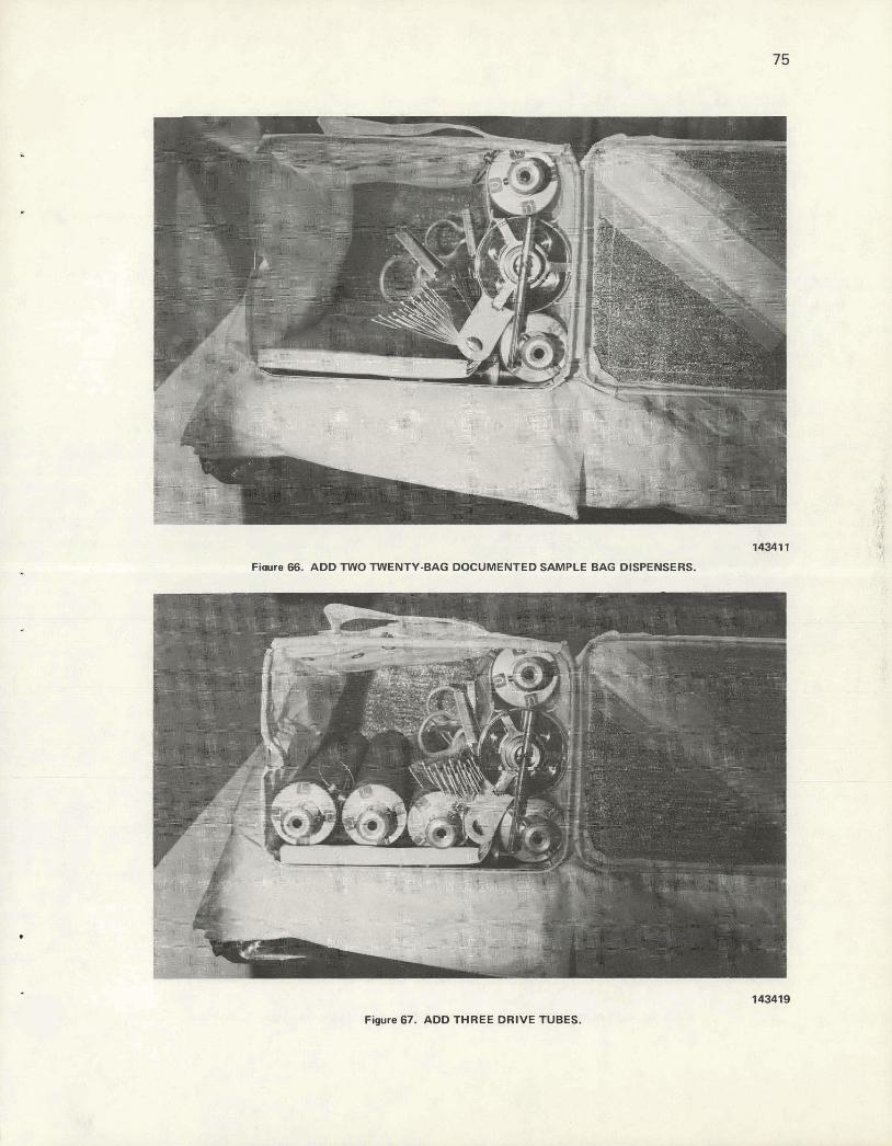
lWl'l Fimre 66. ADD TWO TWENTY-BAG DOCUMENTED SAMPLE BAG DISPENSERS.
143419
Figure 67. ADD THREE DRIVE TUBES.
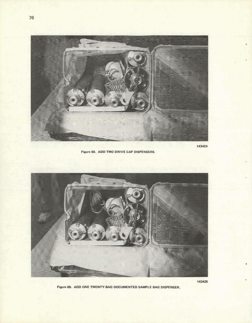
143424
Figure 68. ADD TWO DRIVE CAP DISPENSERS.
14mm F4pm BB* ADD W E mEI;AIW- DcmdmWIED -E BAG D ~ ~ W 1 .

A , , , 22
143426
Figure 70. ADO TWO DRlVE TUBES.
143427
Figure 71. ADD ONE TWENTY BAG DOCUMENTED SAMPLE BAG DISPENSER
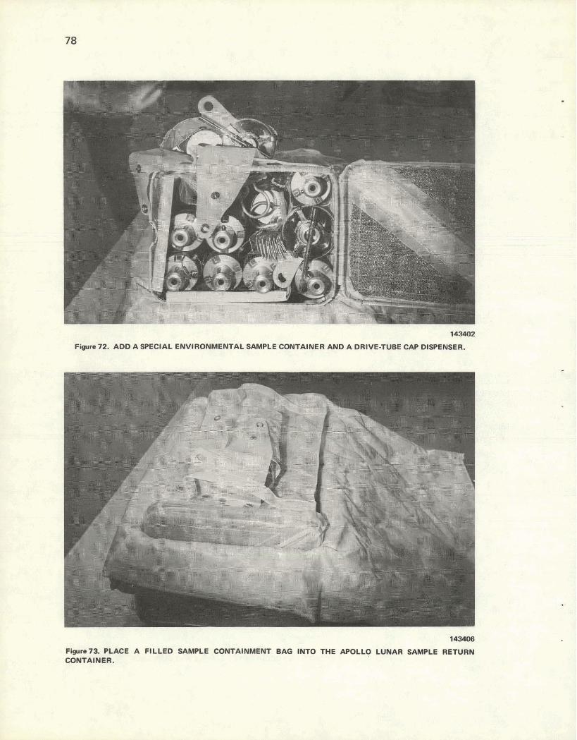
lauu! Figure 72. ADD A SPECIAL ENVIRONMENTAL SAMPLE CONTAINER AND A DRIVE-TUBE CAP DISPENSER.
143406
Fiire73. PLACE A FILLED SAMPLE CONTAINMENT BAG INTO THE APOLLO LUNAR SAMPLE RETURN CONTAINER.
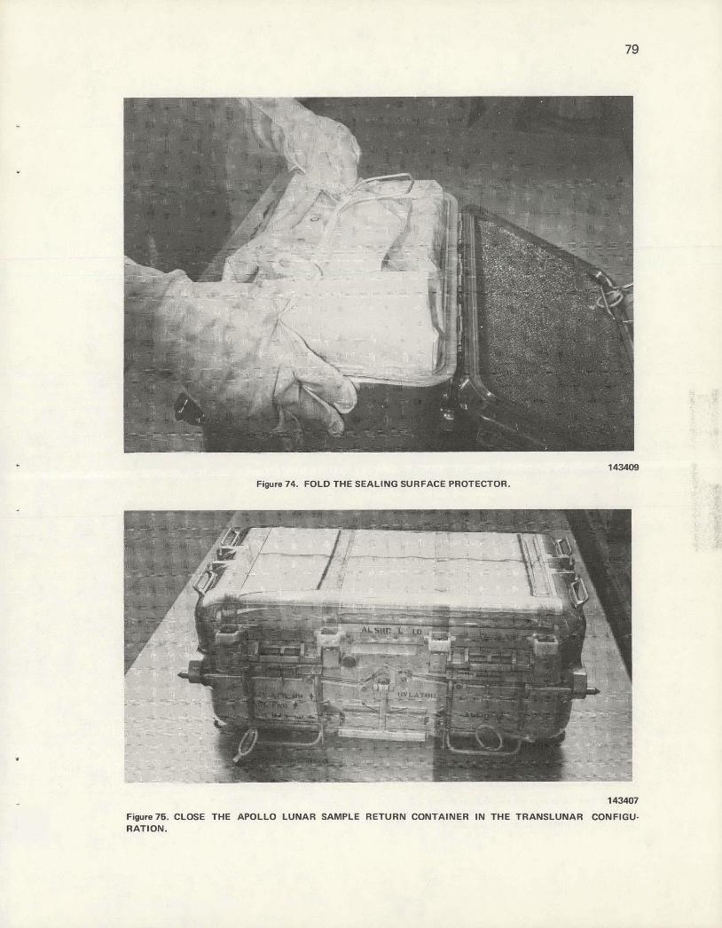
-- I- 143409
Figure 74. FOLD THE SEALING SURFACE PROTECTOR.
Figure76. CLOSE THE APOLLO LUNAR SAMPLE RETURN CONTAINER IN THE TRANSLWNAR CONFIGU- RATION.
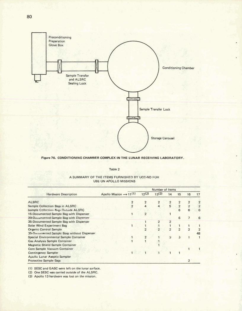
Conditioning
Sample Transfer Lock
Storage Carousel
Chamber
Figure 76. CONDlTlONlNG CHAMBER COMPLEX IN THE LUNAR RECEIVING LABORATORY.
Table 2
A SUMMARY OF THE ITEMS FURNISHED BY UCC-ND FOH USE ON APULLO MISSIONS
Number of Items
Hardware Description ApolloMirion-+11(1) 12(2) 13(3) 14 15 16 17
ALSRC 2 2 2 2 2 2 2 Sample Collection Bags in ALSRC 2 4 4 5 2 2 2 %;ample C~lHizmr Ralp O~rtaide ALERC 6 6 6 15Documented Sample Bag with Dispenser 1 2 'I P D k u m t o d &le Boa with Dinpencr 6 7 6 35Documented Sample Bag with Dispenser 1 2 2 Solar Wind Experiment Bag 1 1 1 1 1 1 1 Organic Control Sample 2 2 2 2 2 2 3 f F . D D u ~ ~ i t e d Campl~ Baa without Dispenser 48 Special Environmental Sample Container 1 2 1 3 3 1 1 Gas Analysis Semple Container 1 1 1 Magnetic Shield Sample Container 1 Core Sample Vacuum Container 1 1 Contingency Sampler 1 1 1 1 1 Alx,llu Lunar Aseptic hmpler Protective Sample Bags 2
(1 ) SESC and GASC -re left on the lunar surface. (2) One SESC WBS carried outside of the ALSRC. 13) Apollo 13 hardware was lost on the mission.

performance Analysis of the ALSRC Hardware
All items of hardware functioned reasonably well during their usage on the various missions. All ALSRCs were structurally sound when they returned to earth, and several were even used again on later flights after being refurbished. This reuse necessitated a slight modification of the gas analysis port, but it did not compromise the integrity of the vacuum container.
Several of the ALSRCs did not maintain a vacuum through the transearth portion of the mission, but these failures were not due to structural defects. Each time an ALSRC failed it was found that a foreign object (eg, fabric from the SCB, dust, or even an aluminum bag tab) had managed to get into the seal area. The ALSRCs that did maintain a vacuum had a pressure between 50 and 100 millitorr when they were received a t the LRL.
The only failure of an inner container was one GASC which was damaged when an attempt was made to place too large a sample into it. This action damaged the delicate knife edge and prevented the container from sealing.
Several problems were encountered with the various sample collection bags. The originally designed SCBs, made of Teflon film, were found to lose their integrity after being packed in the ALSRC for several weeks and cooled during the flight to the moon. They tore and deformed as they were loaded with sharp lunar rock samples. This type of failure led to the bags being made of the Teflon fabric which worked extremely well. A shortcoming of the documented sample bays in the 15 and 20-bag dispensers was the ease with which these bags tore away from their retainer rings. No attempt was made to modify the dispensers, but cautions were communicated to the astronauts on this subject. The most serious structural failure of any hardware was when a Velcro fastening strap came loose from the protective sample bags on Apollo 16. The problem was traced to the type of adhesive used to attach the Velcro straps to the Teflon bags. But, since this item of hardware was not scheduled for another mission, no design change was made. The sample was, however, returned in the protective sample bag in spite of the failure.
Overall performance of the hardware furnished by UCC-ND for the Apollo program was considered excellent. With only a few minor exceptions, there were no failures due tn faulty design or fabrication ot the hardware. The mission of the Apollo program, as stated in the Introduction, was successfully achieved, in part, by the performance and reliability of this hardware. And, since the design remained dynamic, this reliability improved with each mission.

ACKNOWLEDGEMENTS
We wish to acknowledge the valuable scientific and technical contributions made to this project hy personnel from the Oak Ridge National Laboratory, the Oak Ridge Gaseous Diffusion Plant, and the Oak Ridge Y-12 Plant.
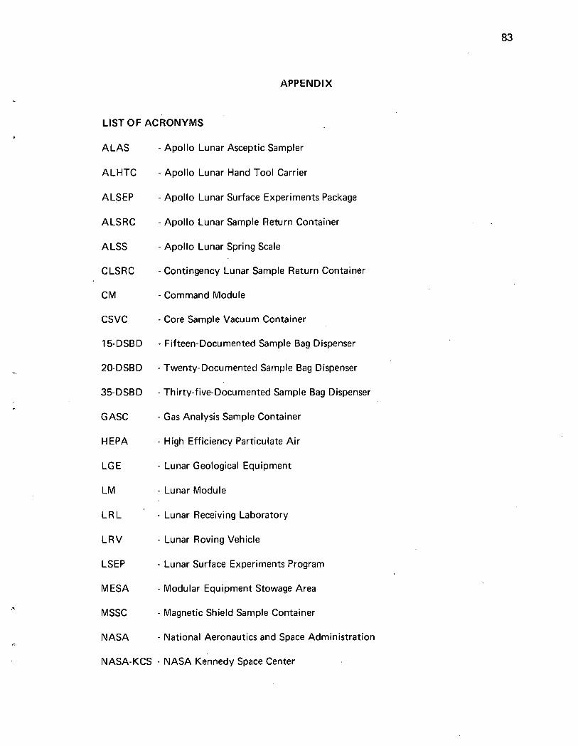
APPENDIX
LIST OF ACRONYMS
ALAS - Apollo Lunar Asceptic Sampler
ALHTC - Apollo Lunar Hand Tool Carrier
ALSEP - Apollo Lunar Surface Experiments Package
ALSRC - Apollo Lunar Sample Return Container
A LSS - Apollo Lunar Spring Scale
CLSRC - Contingency Lunar Sample Return Container
CM - Command Module
CSVC - Core Sample Vacuum Container
15-DSBD - Fifteen-Documented Sample Bag Dispenser
20-DSBD - Twenty- Documented Sainple Bag Dispenser
35-DSBD - Thirty-five-Documented Sample Bag Dispenser
G ASC - Gas Analysis Sample Container
H EPA - High Efficiency Particulate Air
LG E - Lunar Geological Equipment
LM - Lunar Module
LRL - Lunar Receiving Laboratory
LRV - Lunar Roving Vehicle
LSEP - Lunar Surface Experiments Program
MESA - Modular Equipment Stowage Area
MSSC - Magnetic Shield Sample Container
NASA - National Aeronautics and Space Administration
NASA-KCS - NASA Kennedy Space Center
NASA-MSC - NASA Manned Spaceflight Center
ORO-AEC - Oak Ridge Operations of the USAEC
OSB - Organic Sample Bag
PC A - Precision Cleaning Age,nt
P LSS - Portable Life Support System
PSB - Protective Sample Bag
RF - Radio Frequency
SC R - Sample Containment Bag
SESC - Special Environmental Sample Container
SSP - Sealing Surface Protector
SWCCB - Solar Wind Composition Containment Bag
TLV - Threshold Level Value
UCC-ND - Union Carbide Corporation-Nuclear Division
USAEC - United States Atomic Energy Commission
VLF - Vertical Laminar Flow

DISTRIBUTION
Atamic Energy Commission - OR0
Hickman, H. D. (6)
NASA-MSC - Houston
Gerke, P. D. (100)
Oak Ridge Gaseous Diffusion Plant
Wilcox, W. J., Jr Winkel, R. A.
Oak Ridge Y-12 Plant
Denny, A. (2) Keith, Alvin Mitchel, G. W. Y-12 Central Files (10) Y-12 Central Files (master copy) Y-12 Central Files (route) Y-12 Central Files (Y-12RC) Y-12 Development Division (25) Y-12 NASA Project Office (1 00)
Paducah Gaseous Diffusion Plant
Levin, R. W.
In addition, this report is distributed in accordance with the category UC-38, Engineering and Equipment, as given in the USAEC Standard Distribution Lists for Unclassified Scientific and Technical Reports, TID-4500.
Related Documents