15ME0212-20180509-trh-BS-Apollo Bay Development Revised Report 01 .docx TH 9/05/18 | Page 1 of 14 Melbourne Office L3 289 Wellington Parade South EAST MELBOURNE VIC 3002 t +613 9622 9700 [email protected] Bendigo Office L1 133 McCrae Street BENDIGO VIC 3550 t +613 5442 6333 [email protected] Darwin Office 82 Smith Street DARWIN NT 0800 t +618 8980 5900 [email protected] www.irwinconsult.com.au Directors Joe Bruno Neil Clarke Phil Gardiner Peter Hale Barry Roben Member Green Building Council Australia ABN 89 050 214 894 Apollo Bay Resort Town Planning Submission Report 10 TH May 2018 Revision 01 Job no: 15ME0212

Welcome message from author
This document is posted to help you gain knowledge. Please leave a comment to let me know what you think about it! Share it to your friends and learn new things together.
Transcript

15ME0212-20180509-trh-BS-Apollo Bay Development Revised Report 01 .docx TH 9/05/18 | Page 1 of 14
Melbourne Office L3 289 Wellington Parade South EAST MELBOURNE VIC 3002 t +613 9622 9700 [email protected]
Bendigo Office L1 133 McCrae Street BENDIGO VIC 3550 t +613 5442 6333 [email protected]
Darwin Office 82 Smith Street DARWIN NT 0800 t +618 8980 5900 [email protected] www.irwinconsult.com.au
Directors Joe Bruno Neil Clarke Phil Gardiner Peter Hale Barry Roben
Member Green Building Council Australia
ABN 89 050 214 894
Apollo Bay Resort Town Planning Submission Report
10TH May 2018 Revision 01
Job no: 15ME0212

Apollo Bay Resort | Town Planning Submission Report Apollo Bay Resort 9/05/2018 | Page 2 of 14

Apollo Bay Resort Town Planning Submission Report
15ME0212-20180509-trh-BS-Apollo Bay Development Revised Report 01 .docx TH 9/05/18 Page 3 of 14
Page 3 of 14
Document Control
Project Title: Apollo Bay Resort
Project No: 15ME0212
Irwinconsult has prepared this report with the following conditions:
The report may only be used by the client for the purpose for which it was commissioned.
The report may only be reproduced in full.
The report shall not be considered as relieving any other party of their responsibilities, liabilities or contractual obligations.
The report addresses the engineering disciplines noted within only.
The report does not address the presence of asbestos or other contaminative materials.
Contents
1 Executive Summary ........................................................................................ 5
General ........................................................................................................................................ 5
Panel Directions Responses ..................................................................................................... 5
2 Introduction ..................................................................................................... 6
General ........................................................................................................................................ 6
Title & Subdivision ..................................................................................................................... 6
Site Infrastructure....................................................................................................................... 6
Clarifications ............................................................................................................................... 6
3 Hydraulic Services .......................................................................................... 7
Authority infrastructure ............................................................................................................. 7
Site Sewer Infrastructure ........................................................................................................... 7
Water Supply .......................................................................................................................................... 7 Sewer Drainage .......................................................................................... Error! Bookmark not defined.
Site Gas Infrastructure ............................................................................................................... 7
Proposed Hotel - Hydraulic Services ........................................................................................ 7
Sewer Drainage ...................................................................................................................................... 7 Trade Waste ............................................................................................................................................ 7 Water Service Connections ................................................................................................................... 7 Hot Water Service .................................................................................................................................. 7 Rainwater Harvesting and Reuse ......................................................................................................... 7
4 Electrical Services .......................................................................................... 9
General ........................................................................................................................................ 9
Authority infrastructure (existing) ............................................................................................. 9
Site Electrical Infrastructure (proposed) .................................................................................. 9
Site Communications Infrastructure ......................................................................................... 9
Proposed Hotel - Electrical Services......................................................................................... 9
Internal infrastructure ............................................................................................................................ 9 Lighting ................................................................................................................................................... 9 Lighting Control System ....................................................................................................................... 9 Emergency & Exit Lighting ................................................................................................................... 9 General Power ........................................................................................................................................ 9 Communications Systems .................................................................................................................... 9 Security & CCTV ..................................................................................................................................... 9
Proposed Hotel Villas – Electrical Services ............................................................................ 10
Proposed Resort Villas – Electrical Services ......................................................................... 10
On-Site power Generation ....................................................................................................... 10
PV Generation....................................................................................................................................... 10 Requirements for on-site generation ................................................................................................. 10 Panel/ Array Sizes ................................................................................................................................ 10 Electrical Works ................................................................................................................................... 10
5 Mechanical Services ..................................................................................... 11
General ...................................................................................................................................... 11
Revision Date File name 15ME0212-20170628-LRB-BS-Apollo Bay Development Report - P3.docx
P3 28.06.2017
Description 40% SD
Prepared Checked Approved
Initial LRB TH1 PGH
Date 28.06.2017 28.06.2017 29.06.2017
A 10/10/2017
File name 15ME0212-20171010-LRB-BS-Apollo Bay Development Report - A
Description Concept Design
Prepared Checked Approved
Initial LRB PGH PGH
Date 10/10/2017 10/10/2017 10/10/2017
01 10/05/2018
File name 15ME0212-20180509-trh BS-Apollo Bay Development Revised Report 01.docx
Description Town Planning Submission
Prepared Checked Approved
Initial TH1, LRB, MK1, SM1
LRB PH1
Date 10.05.18 10.05.18 10.05.18
File name
Description
Prepared Checked Approved
Initial
Date
File name
Description
Prepared Checked Approved
Initial
Date

Apollo Bay Resort Town Planning Submission Report
15ME0212-20180509-trh-BS-Apollo Bay Development Revised Report 01 .docx TH 9/05/18 Page 4 of 14
Page 4 of 14
Proposed Hotel - Mechanical Services .................................................................................... 11
Proposed Resort Villas – Mechanical Services ...................................................................... 11
Heat Rejection System ............................................................................................................. 11
6 Fire Services .................................................................................................. 12
General ...................................................................................................................................... 12
Building Surveyor ..................................................................................................................... 12
Fire Authority ............................................................................................................................ 12
Fire Engineer ............................................................................................................................. 12
Authority infrastructure ............................................................................................................ 12
Site Wet Fire Infrastructure ...................................................................................................... 12
Site Dry Fire Infrastructure ....................................................................................................... 13
7 Appendix ........................................................................................................ 14

Apollo Bay Resort Town Planning Submission Report
15ME0212-20180509-trh-BS-Apollo Bay Development Revised Report 01 .docx TH 9/05/18 Page 5 of 14
Page 5 of 14
1 Executive Summary
General
The following updated report outlines the availability of authority infrastructure services to the site and provide concept design for the proposed resort development. The previous report was based on the original planning application. This revision of the report reflects the changes made to the proposed development as follows;
Removal of any works associated with the proposed Stage 2 development.
Relocation of all buildings and the associated services to outside of the “very high” risk zone defined in the Golder Report November 2017.
Panel Directions Responses
This report has been issued for the revised Town Planning application. Planning Panels Victoria has provided panel directions in their letter dated 28 March 2018 which require a response. The responses in relation to the services items are as follows;
Direction 1(h) - “An updated report that details how mobile phone / internet access will be managed and potentially augmented on site in response to objections raised.”
Response: According to the NBN website the NBN roll out proposed for the Barham River Road area is for Fixed Wireless connection which required wireless transmission between a tower base station to a roof top mounted antenna for the facility. This is proposed between July to December 2019. NBN Co. has verbally advised that a direct fibre connection could be provided instead at an earlier date given that there are other FTTP and FTTN connections nearby. Telstra and Optus mobile phone coverage maps indicate 4G capability with speeds 2-75MBPS.
Direction 1(i) - “ Details of how lighting can be managed to minimise visual impact and light pollution.” Response: Minimal external light for path/roadways will be provided for the purpose of amenity and security. The external lighting design will be undertaken to minimising upward components and light spill to adjacent areas in accordance with AS 4282 – Control of the obtrusive effects of outdoor lighting.

Apollo Bay Resort Town Planning Submission Report
15ME0212-20180509-trh-BS-Apollo Bay Development Revised Report 01 .docx TH 9/05/18 Page 6 of 14
Page 6 of 14
2 Introduction
General
Irwinconsult have been engaged to investigate the availability of authority infrastructure services to the site and provide advice for the revised Town Planning Scope. This report considers the disciplines of:
Hydraulic services
Electrical services
Mechanical Service
Fire Protection Services
This report refers to the revised master site plan as issued by Spowers Architecture.
Title & Subdivision
The following report details our servicing infrastructure assessment on the basis of the proposed facilities as shown on the architectural concept drawings. We understand the site titles will be will be maintained as is. No further subdivision is proposed or title arrangement changed from our current understanding.
Site Infrastructure
The report details our current knowledge of the existing authority services on or near the proposed site, and the status of our negotiations with the services’ authorities in respect to bringing these services into the site to support the proposed development.
Clarifications
Irwinconsult releases this report subject to the following conditions and qualifications.
This report shall only be used for the purpose for which it was commissioned and in accordance with the corresponding Irwinconsult Conditions of Engagement.
This report shall only be reproduced in full.
This report shall not be considered as relieving any other party of their responsibilities, liabilities nor contractual obligations.
No testing of existing services and structure has been carried out.

Apollo Bay Resort Town Planning Submission Report
15ME0212-20180509-trh-BS-Apollo Bay Development Revised Report 01 .docx TH 9/05/18 Page 7 of 14
Page 7 of 14
3 Hydraulic Services
Authority infrastructure
Irwinconsult have lodged an application with Barwon Water (Local Water Authority) to obtain preliminary servicing advice for water and sewer provisions for the site. Barwon Water have provided a formal response via Technical memo dated 21st April 2017 and further advice via emails dated 13th December 2018 and 1st May 2018.
Site Sewer Infrastructure
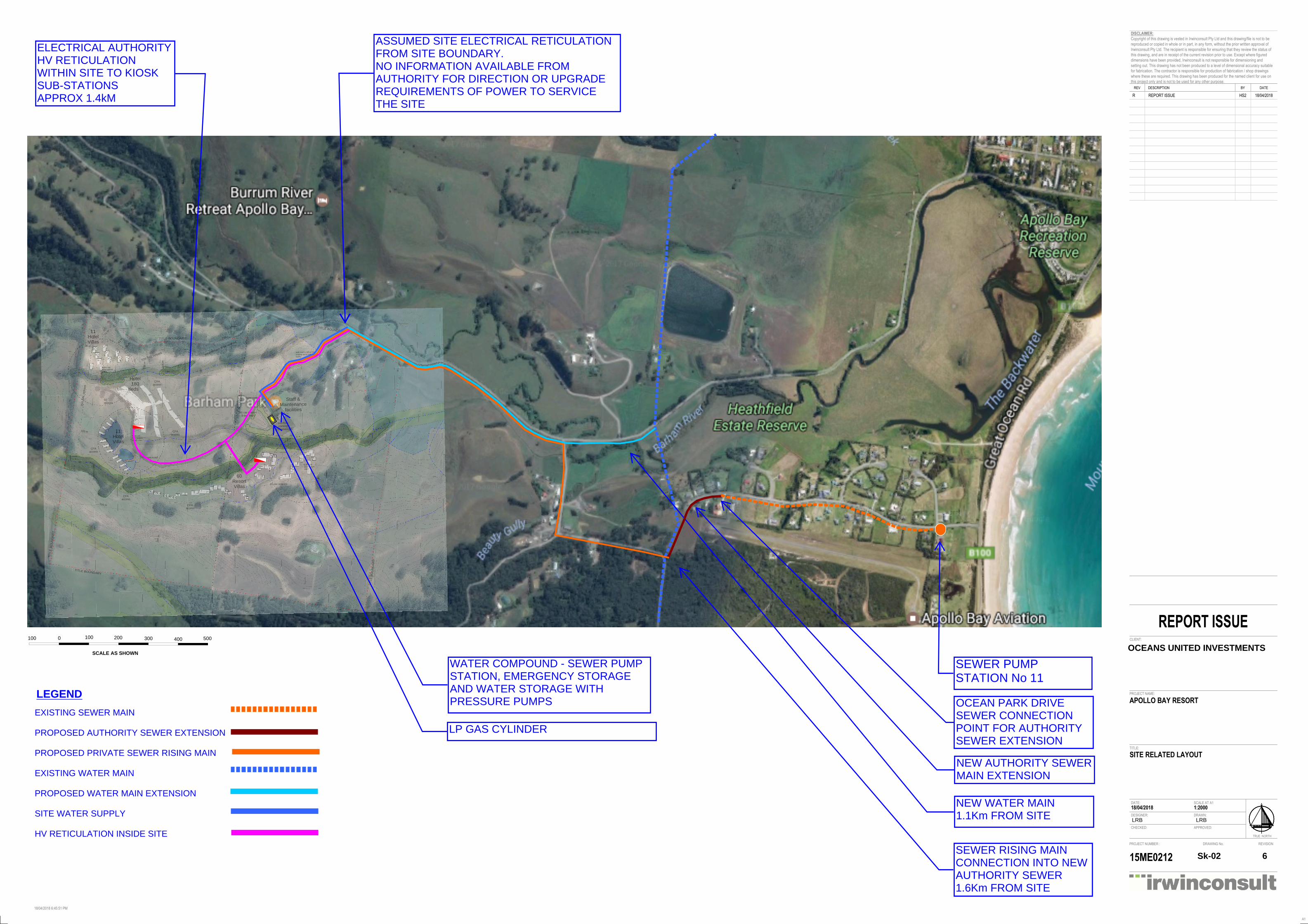
The development site is remote from the Barwon Water sewer and water supply networks. Barwon Water have advised that the site will require modifications to the Barwon Water infrastructure as described below. This will include the following: Privately owned sewer infrastructure within the site Privately owned sewer pump station and emergency storage Private sewer rising main toward the Barwon Water designated connection point Barwon Water sewer main extension from No.43B Ocean Park Drive across to Telfords Acc Road where the
sewer rising main will connect.
Water Supply
The property at 305 Barham River Road is not directly fronted by a Barwon Water reticulation potable water main. The existing water main fronting the site carries raw water and is unsuitable for supplying customers directly. The nearest main that is available for supply of this property is the DN250 AC main which crosses Barham River Road approximately 1.1km to the east of the site. Barwon Water have advised that the site will require modifications to the Barwon Water infrastructure as described below. This will include the following: Barwon Water owned and operated water main from the pipeline offtake along Barham River Road to the site
water supply compound. Water meter will be located at the end of the Barwon Water main outside the water supply compound. Privately owned and operated tank and booster pump station in accordance with the development requirements
to transfer the water supply to the Hotel Building for site storage and pressure pump site reticulation. The site water supply and sewer infrastructure described above will be located in a services compound adjacent to the Maintenance Shed.
Site Gas Infrastructure
The gas authority mapping system indicates that Apollo Bay area is not serviced by natural gas. Local gas supply is provided by LPG. For this facility onsite bulk LPG gas storage vessels will be provided to service the site for cooking, hotel domestic hot water, gas log fires and pool heating requirements. The gas cylinder is sized by the LPG supplier based volume of gas used on site and regularity of service distribution by LPG tankers in the area. Normally LPG cylinder filling is done on a 3-4-week basis. The gas reticulation around the site would be by in ground piping at high pressure (70Kpa-100Kpa) to each of the buildings that require gas. Gas regulators are provided to regulate the gas down to consumer levels (2.85Kpa) for connection to the appliance. The LPG cylinder will be located near the combined services/maintenance sheds to allow off cylinder filling without restricting access to the facility. Tanks will be located with a compound and will maintain required distances from buildings and other infrastructure assets in accordance with gas authority requirements. This includes access for filling and protection from accidental vehicle impact.
Proposed Hotel - Hydraulic Services
Sewer Drainage
It is proposed to install a gravity drainage system for all hydraulic fixtures and items of equipment, reticulating to the onsite sewer pump station Where contouring does not allow a gravity connection into the main drainage system, additional pump stations will be provided to lift the sewer to a gravity point of the main system. Internal sanitary plumbing and sewer drainage is to be installed in accordance with the requirements of AS3500 Part 2. Sewer maintenance holes will be provided at major changes in junctions to provide suitable access for maintenance purposes.
Trade Waste
A complete greasy waste drainage system is to be installed to collect waste from fixtures and items of equipment located within the commercial kitchen(s). Grease interceptor traps (GIT) will be provided in accordance with Barwon Water Trade Waste requirements. Exact sizing of GITs is to be further assessed during detailed design. Straining & Cooling Pits are to be provided for waste from the commercial laundry. Exact sizing of pits is to be further assessed during detailed design.
Water Service Connections
The site water supply will be extended from the Barwon Water meter assembly and discharge into a break tank in the water compound near the maintenance sheds. A transfer pump will carry the water supply to the hotel plantroom at the top of the site where it will discharge into a storage tank. Pressure pumps will reticulate the water supply throughout the hotel building and to each individual building on site. Isolation valves and pressure control valves will be provided for pressure control and maintenance purposes.
Hot Water Service
For the major facilities a centralised solar pre-heated, instantaneous gas boost hot water plant will be provided within the plant room of the hotel building. Hot water circulating loops will reticulate hot water to fixtures and items of equipment throughout the facility so that hot water is readily available at all outlets. Localised thermostatic/tempering valves will be installed to provide tempered water to fixtures used for personal hygiene, ie: basin, showers etc. Temperature control valves will be installed at low level in readily accessible location to allow for required maintenance. The remote buildings will be provided with instantaneous LPG hot water units.
Rainwater Harvesting and Reuse
It is proposed to provide the facility with a rainwater harvesting and reuse system for toilet flushing. Assessment of rainwater harvesting for the site has been undertaken utilising MUSIC modelling software. After assessing multiple demand and catchment options, the most feasible and effective solution is to provide a 150KL underground concrete rainwater tank, collecting water from the main hotel building, to meet the toilet flushing demand for the site. The results and assumptions are as follows:
Annual average of 90% occupancy (from a possible total of 420 persons per day)
Roof area from main hotel building: 6000m2
20L/person/day toilet flushing demand
Daily demand 7.56kL
Annual rainwater runoff available 4750kL
Apollo Bay Resort Town Planning Submission Report
15ME0212-20180509-trh-BS-Apollo Bay Development Revised Report 01 .docx TH 9/05/18 Page 8 of 14
Page 8 of 14
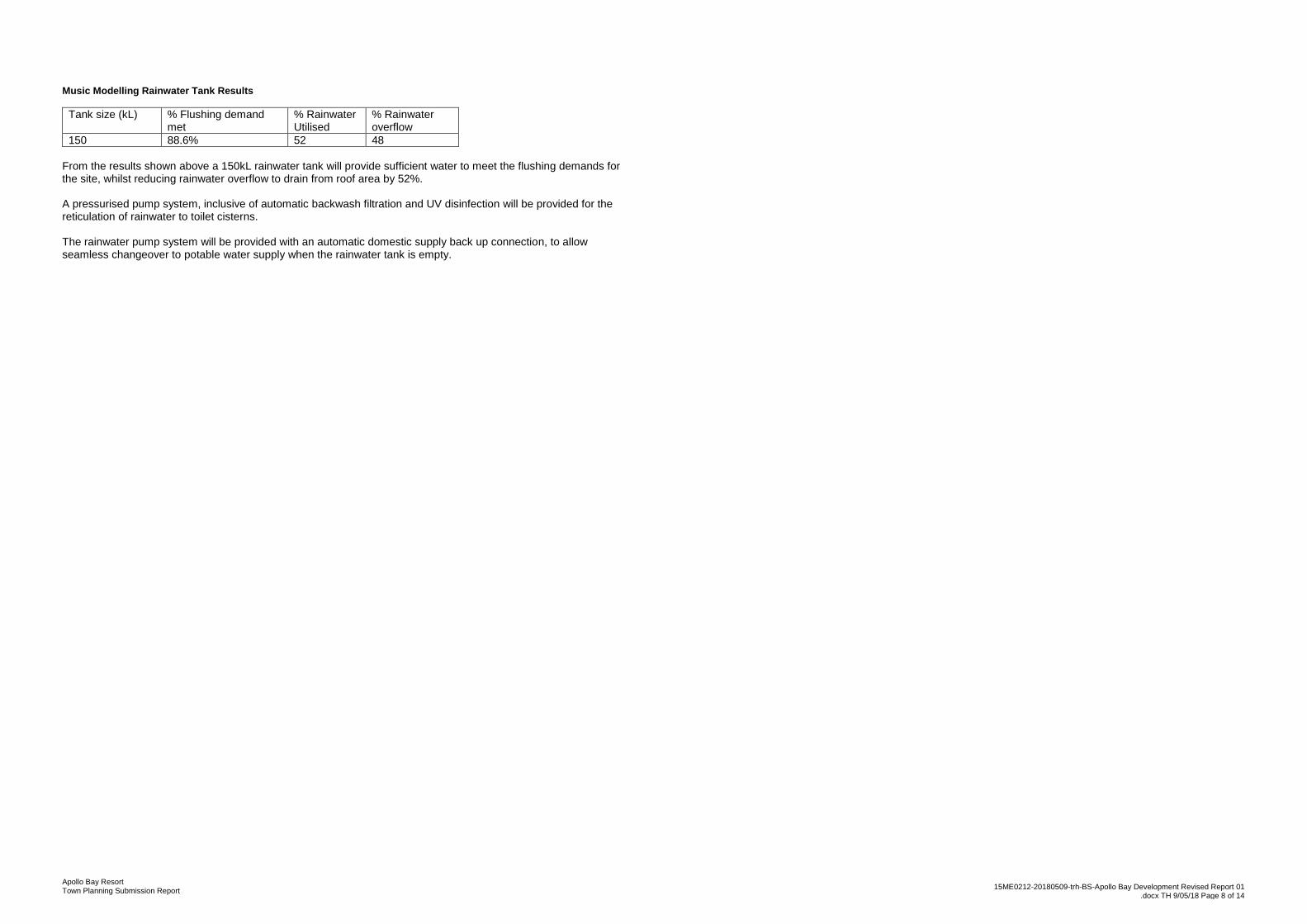
Music Modelling Rainwater Tank Results
Tank size (kL) % Flushing demand met
% Rainwater Utilised
% Rainwater overflow
150 88.6% 52 48
From the results shown above a 150kL rainwater tank will provide sufficient water to meet the flushing demands for the site, whilst reducing rainwater overflow to drain from roof area by 52%. A pressurised pump system, inclusive of automatic backwash filtration and UV disinfection will be provided for the reticulation of rainwater to toilet cisterns. The rainwater pump system will be provided with an automatic domestic supply back up connection, to allow seamless changeover to potable water supply when the rainwater tank is empty.

Apollo Bay Resort Town Planning Submission Report
15ME0212-20180509-trh-BS-Apollo Bay Development Revised Report 01 .docx TH 9/05/18 Page 9 of 14
Page 9 of 14
4 Electrical Services
General
The electrical services installations will be designed in accordance with the relevant requirements of the BCA, the Australian Standards referred to therein and all relevant authorities having jurisdiction over the works.
Authority infrastructure (existing)
The authority has verbally advised that the electrical supply in the vicinity of the site will need to be upgraded to support the proposed development. Preliminary advice from the Electrical Supply Authority indicates that they will need to complete detailed electrical investigation prior to issuing a formal supply offer and advice regarding this new H.V. supply. It has been proposed that aerial power lines observed throughout the site shall be relocated underground (by Supply Authority) while Powercor undergoes their required infrastructure upgrade works throughout the vicinity.
Site Electrical Infrastructure (proposed)
Based on preliminary Electrical demand calculations, we have assessed that the site will require 2no. substations to provide electrical supply:
1. 1500kVA kiosk substation – feeds Hotel and Hotel Villas 2. 1000kVA kiosk substation – feeds Resort Villas and Staff & Maintenance Facilities.
Powercor has been contacted regarding the preliminary electrical demand for the site and initial liaison has commenced. As stated previously, as there are not adequate Supply Authority assets nearby, Powercor has submitted an SDSC Offer to undergo detailed investigation prior to issuing a formal supply offer. They have stated that they are unable to provide any further information until they have received the signed and accepted offer. The dimensions and access requirements of the kiosk substations are as follows: Kiosk 1000kVA and 1500kVA substations:
Easement Requirements: 7.2m(W) x 7.2m(L) – Typical dimensions for substation of size 500kVA to 2000kVA.
Kiosk size (above ground): 2.6m(W) x 2.115m(L).
Carriageway clear access in front of substation: 4m(L).
Clear access head height in front of substation for truck access: 5m(H).
HV cable easement: 2m(W) x Length of cable run.
The substation can be fenced/ screened off (clients decision) at easement boundaries.
Site Communications Infrastructure
Internet
Standard NBN installation is estimated for Jul-Dec 2019 used fixed wireless, requiring a roof-top antenna. Alternatively, NBN Co has verbally advised that a fibre connection to the site could be provided at an earlier timeframe given the proximity to FTTP and FTTN connections nearby. A communications room of dimensions 4m x 3m is located within the Hotel building to allow for distribution of NBN to the hotel, villas and staff & maintenance facilities.
Mobile phone coverage
Optus and Telstra coverage maps both indicate that 4G services are available to the entirety of the site.
Proposed Hotel - Electrical Services
Internal infrastructure
Supply for the hotel will be achieved via the kiosk/ indoor substation and terminated into a new Main Switchboard/ Meter panel located within the main switchroom. This main switchboard will then feed a number of distribution boards on each level to feed power to the separate hotel rooms.
Lighting
Lighting throughout the Hotel will be designed in accordance with AS/NZS 1680 and for maximum flexibility to suit the various intended uses of the different areas/ rooms. Lighting will generally be comprised of energy efficient LED luminaires. LED drivers will typically be of the high frequency electronic type while luminaires will also be selected which are easily maintainable. External lighting will be provided to the Hotel entrance areas and perimeter for safety, security and landscape features. Minimal external light for path/roadways will be provided for the purpose of amenity and security. This lighting will be tested to comply with AS 4282 – Control of the obtrusive effects of outdoor lighting. It is understood that there will be no architectural uplighting (eg, onto building facades or landscaping elements).
Lighting Control System
A lighting control and energy management system (LCS) will be provided to meet the requirements of the BCA and minimise energy consumption and unnecessary artificial lighting. The LCS will be provided with the following basic features proposed:
Motion detector control of lighting;
Timer and sunset switch controls for external lighting;
Daylight sensors to control interior lighting adjacent to windows receiving daylight
Interface to security system for master controls of lighting (i.e. all off when building armed, all lights on when intruder detected, etc.);
At this stage, it is not proposed to use a networked lighting control system. Instead, a standalone system comprising of motion sensors will be provided to meet the requirements of the BCA.
Emergency & Exit Lighting
A centrally monitored emergency and exit lighting will be provided throughout the Hotel in accordance with AS/NZS 2293, the BCA and the building surveyor’s requirements. The exit signs will be of the pictograph (“walking man”) type.
General Power
Power outlets will be provided throughout the building as per room data sheets and equipment details, also to suit audio visual requirements and supply to other services equipment and motorised architectural elements.
Three phase power outlets in public areas to be key lockable.
Floorboxes will be provided around the building as required, complete with power outlets.
Communications Systems
The communications cabling installation will be provided in accordance with the relevant requirements detailed in the appropriate Australian Standards and good design practice.
A CAT6A structured cabling solution will be provided for data and voice connectivity throughout the building, consisting of patch panels, RJ45/ 4 pair outlets, fixed horizontal cabling, patch and fly leads from a single manufacturer. Reference will be made to the preferred cabling vendors, eg TE, Commscope, Panduit, Siemon or Molex. We note that the active data network design and configuration and the provision of the associated equipment (ie. servers, switches, routers, wireless access, UPS’s, PC’s printers, etc.), etc., will be implemented by the Hotel as appropriate. Floorboxes will be provided as required in conference facilities, complete with CAT 6A communications outlets. The following systems will also be provided (all new) :
MATV
Hearing augmentation Technical requirements for these systems will be provided as the design develops.
Security & CCTV
Access Control and Intruder Detection
The Hotel’s preferred security services provider will be engaged to install a security system throughout the area.

Apollo Bay Resort Town Planning Submission Report
15ME0212-20180509-trh-BS-Apollo Bay Development Revised Report 01 .docx TH 9/05/18 Page 10 of 14
Page 10 of 14
Proposed Hotel Villas – Electrical Services
Supply for the 22 off hotel villas will be via the Main Switchboard located within the hotel main switchroom. Two distribution boards will subsequently feed the separate villa areas (North of the hotel vs. West of the hotel). Separate load centres will be provided within the entrance hall of each hotel villa to provide local switching and protection.
Proposed Resort Villas – Electrical Services
Supply for the 60 off resort villas will be via a new Main Switchboard located near the resort villa substation. Each villa area will be separated into a number of zones (up to 10 - 20no. villas per zone) with a dedicated distribution board for each zone. Separate load centres will be provided within the entrance of each resort villa to provide local switching and protection.
On-Site power Generation
We have reviewed the following on-site power generation strategies which could be implemented to supplement the mains supply:
PV Generation
As an option, an indicative cost for PV generation is $1.70per watt (not including on site battery storage). This price is for standard non-adjustable mounting brackets and based on optimal weather conditions.
Requirements for on-site generation
It is recommended that the system capacity should not exceed 100 kW as this is the threshold that deems a system to be “large scale”, which means that the RET subsidies are not paid at the time of installation but are paid over the lifetime of the system. Also a large system has to be formally registered as a power station with the Clean Energy Regulator.
Panel/ Array Sizes
Solar PV panels are available in a number of different sizes and capacities. For a system such as this, a typical solar PV panel is rated at 330W output and is approx. 1.56m x 1.05m in size and weighs approximately 18.6kg. There are more efficient panels on the market that can achieve a higher output for the same size but generally these are more expensive per kW and only recommended if space is limited. Care should also be taken to offer the best options in locating the PV cells and maintaining safe access. It is proposed to locate the panels on ground in an array adjacent to the overflow carpark. A 99kW installation would require approximately 300 panels equating to a PV panel area of 491m2. This installation would also require space between rows of panels to allow for access and maintenance purposes. The panels will be installed on frames (tilted up) with the rows of panels spaced appropriately to prevent overshadowing between panels. As an example, a tilt angle of 10° would require spacing between rows of 600mm. Using an array of 20 rows with 15 panels per row would hence result in a panel installation covering 42.6m x 15m, or 639m2.
Electrical Works
A new distribution board, PV inverter and associated accessories will be required for the complete installation.
Apollo Bay Resort Town Planning Submission Report
15ME0212-20180509-trh-BS-Apollo Bay Development Revised Report 01 .docx TH 9/05/18 Page 11 of 14
Page 11 of 14
5 Mechanical Services
General
Based on current information, the following section provides a brief outline of the proposed Mechanical Services systems associated with The Apollo Bay Resort. The Mechanical Services installation will be designed in accordance with the relevant requirements of BCA, the relevant Australian Standards, and the requirements of all authorities with jurisdiction over the works. The various mechanical options that could be considered have been assessed against the following briefed building features and/or design requirements:
Mechanical Ventilation for common areas;
Natural Ventilation for Hotel rooms;
Each individual room requires independent temperature control;
Occupancy times of the hotel areas varies significantly with periods of high occupancy and periods with low occupancy;
Any mechanical system is required to be energy efficient; There are no existing services on site.
Proposed Hotel - Mechanical Services
Option 1
Reverse Cycle Heat Recovery VRV/VRF system comprising of external outdoor air condensers located within a plant either on the roof or hotel BOH at ground level.
Option 2
Centralised High-efficiency Ground Source water-to-air ground source heat pump (GSHP) cooling system (see below).
Proposed Resort Villas – Mechanical Services
Option 1
Reverse Cycle Heat Recovery VRV/VRF system comprising of external outdoor condensers either air-cooled or geo-exchange (see below) located at each villa either on the roof or beside each building.
Option 2
High-efficiency Ground Source water-to-air ground source heat pump (GSHP) cooling system (see below) for each individual villa unit.
Heat Rejection System
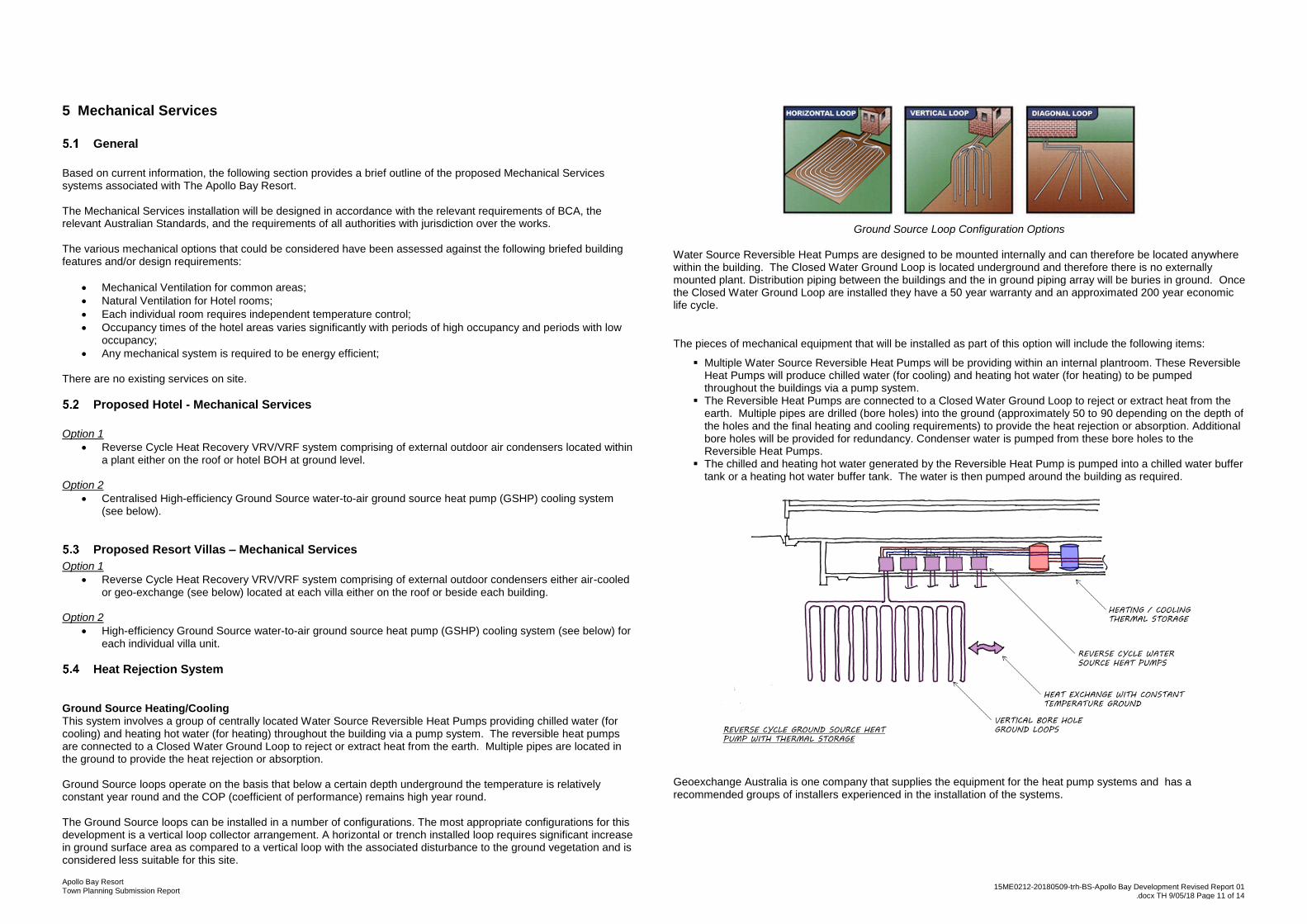
Ground Source Heating/Cooling This system involves a group of centrally located Water Source Reversible Heat Pumps providing chilled water (for cooling) and heating hot water (for heating) throughout the building via a pump system. The reversible heat pumps are connected to a Closed Water Ground Loop to reject or extract heat from the earth. Multiple pipes are located in the ground to provide the heat rejection or absorption. Ground Source loops operate on the basis that below a certain depth underground the temperature is relatively constant year round and the COP (coefficient of performance) remains high year round. The Ground Source loops can be installed in a number of configurations. The most appropriate configurations for this development is a vertical loop collector arrangement. A horizontal or trench installed loop requires significant increase in ground surface area as compared to a vertical loop with the associated disturbance to the ground vegetation and is considered less suitable for this site.
Ground Source Loop Configuration Options
Water Source Reversible Heat Pumps are designed to be mounted internally and can therefore be located anywhere within the building. The Closed Water Ground Loop is located underground and therefore there is no externally mounted plant. Distribution piping between the buildings and the in ground piping array will be buries in ground. Once the Closed Water Ground Loop are installed they have a 50 year warranty and an approximated 200 year economic life cycle.
The pieces of mechanical equipment that will be installed as part of this option will include the following items:
Multiple Water Source Reversible Heat Pumps will be providing within an internal plantroom. These Reversible Heat Pumps will produce chilled water (for cooling) and heating hot water (for heating) to be pumped throughout the buildings via a pump system.
The Reversible Heat Pumps are connected to a Closed Water Ground Loop to reject or extract heat from the earth. Multiple pipes are drilled (bore holes) into the ground (approximately 50 to 90 depending on the depth of the holes and the final heating and cooling requirements) to provide the heat rejection or absorption. Additional bore holes will be provided for redundancy. Condenser water is pumped from these bore holes to the Reversible Heat Pumps.
The chilled and heating hot water generated by the Reversible Heat Pump is pumped into a chilled water buffer tank or a heating hot water buffer tank. The water is then pumped around the building as required.
Geoexchange Australia is one company that supplies the equipment for the heat pump systems and has a recommended groups of installers experienced in the installation of the systems.

Apollo Bay Resort Town Planning Submission Report
15ME0212-20180509-trh-BS-Apollo Bay Development Revised Report 01 .docx TH 9/05/18 Page 12 of 14
Page 12 of 14
6 Fire Services
General
The report covers the following services:
Water Supply.
Fire Service Booster.
Fire Hydrant System.
Fire Hose Reel System.
Fire Pumps.
Fire Tanks.
Automatic Fire Sprinklers.
Fire Panels and Fire Alarm Connection.
Smoke Detection and Smoke Alarms.
Emergency Warning and Intercommunication System (EWIS)
Portable Fire Extinguisher / Fire Blankets
This report is based on the deemed to satisfy (DTS) provisions of the building code of Australia (BCA), Victoria building regulations.
This report is based on the development being built on one consolidated title and all major fire equipment (i.e. FIP / EWIS / Fire Pumps / Fire Tanks / Sprinkler Control Valve Room) is proposed to be provided.
Building Surveyor
Any alternative solutions will be for fire protection will need to be establish by the building surveyor in conjunction with the fire engineer when appointed for the design.
Fire Authority
The fire authority is Country Fire Authority (CFA). We met with Fire Safety Officer Mr Peter Hamilton on 27th June 2017 as a courtesy meeting to discuss in broad principals the proposed fire protection for the site. Items discussed were the water supply issues, fire tank location, fire pump house and booster location and other general firefighting proposals. At this stage there were no objections to the proposals put forward however a formal application will be made as the project detail develops further. Once a fire engineer is engaged and prepared Fire Engineering Brief (FEB), we will organise a further meeting with the CFA. The following Regulation 309 (not limited to) are:
Location of Fire Brigade Booster.
Location of Fire Pumps and Tanks.
Location of Fire Hydrant and distances from a hardstand.
Location of Fire Indicator / Emergency Warning and Intercommunication System (EWIS) Panel.
Providing a fire extinguisher in lieu of a fire hose reel within ‘small’ fire/smoke zones (i.e. plant rooms, smoke lobbies etc.)
Providing a combined hydrant/sprinkler system. Subject to sprinkler requirements.
The use of Magflow.
Fire Engineer
The fire engineer is not yet engaged. Any performance based solutions will need to be provided with an FER which the fire service design will need to comply with. Any bushfire requirements will need to be assessed through a separate bushfire report. The following performance solutions (not limited to) are:
Omit sprinklers at the top of lift shafts and provide a heat detector in lieu.
Omit sprinklers from showers.
Provide a fire test drain within a fire stair.
Omitting sprinklers/fire detection from above the pool area.
Authority infrastructure
Refer to Hydraulics Section. Grade III water supply is required for fire services.
Site Wet Fire Infrastructure
The following site wet fire infrastructure are proposed:
Fire Brigade Booster.
Combined fire hydrant / fire hose reel and automatic sprinkler system fire pumps.
2 x 252,000 effective litre fire tanks located adjacent to the fire pump enclosure.
Automatic sprinkler valves located at each required building feed off the fire service ring main.
Automatic sprinkler system throughout expect areas where not required by code. (Building Surveyor to confirm).
Fire Hydrant System throughout.
Fire Hose Reel throughout the non-accommodation areas.
150mm diameter fire service ring main.
Fire Bridge Booster
To be provided in accordance to AS2419. Location proposed is North-West of the main building adjacent to the fire pump house as shown on the sketches. Final location to be approved by the fire authority.
Fire Pumps
It is proposed to provide two (2) fire pumps (diesel and electric) in accordance to AS2941 to serve the Fire Hydrant / Fire Hose Reel and Automatic Sprinkler System. Fire pump room / shed is also provided.
Location proposed adjacent to the carpark to the east of the hotel as shown on the sketches. Final location to be approved by the fire authority.
Fire Tanks
Propose to provide 2 x 252,000 effective litre tanks and located adjacent to the fire pump room and fire booster assembly. Final location to be approved by the fire authority. Final size of the tanks will be determined once fire engineer is engaged and after the fire authority meeting.
It is proposed to partially bury the tanks to reduce the visual impact, however the levelling of the tanks and booster suction point will need to be considered to avoid affecting the suction. The level at which the tanks can be buried will need to assessed through detailed design referencing RL differentiation between the tanks and booster.
Automatic Sprinkler System
Automatic Fire Sprinklers will be proposed throughout in accordance to AS2118.1 – 1999. Building surveyor / fire engineer to confirm areas that will not be required. Sprinkler valves will be fed off the site wide fire services ring main. Sprinkler valves will be located externally or internally provided they have direct access to open road or space. Final location approved by fire authority.

Apollo Bay Resort Town Planning Submission Report
15ME0212-20180509-trh-BS-Apollo Bay Development Revised Report 01 .docx TH 9/05/18 Page 13 of 14
Page 13 of 14
Fire Hydrants
It is proposed to provide Fire Hydrants throughout in accordance to AS2419. There will be combination of external and internal fire hydrants. In accordance with the National Construction Code (NCC), hydrant protection will need to be provided to buildings which are equal or in excess of 500 sqm floor area. Building which are less than 6m apart will require to be considered as one fire compartment. Therefore, the total floor area will need to be determined and if they are in excess of 500 sqm they will be required to be served by a hydrant system. External fire hydrants are to be located more than 10m from building outline or if next to the building within Fire Resistant Level (FRL) of not less than 90/90/90 2m each side and 3m above the fire hydrant. Any openings within 10m horizontally and vertically to be protected with internal sprinklers within 500mm of the opening. To be located not more than 50m from a hardstand. To be located not closer than 10m from high voltage. Internal fire hydrant is to be located within 4m from a non-fire isolated stair and / or within fire isolated stairs. Fire Hose Reels Fire Hose Reels to be in accordance to AS2441 Requires 100mm clearance around drum to door jam. Required to be located no more than 4m from building exits, fire escapes and shall provide coverage via 36m hose throughout building. Site wide fire service ring main The site will be provided with a 150mm diameter fire service ring main.
Site Dry Fire Infrastructure
The following site dry fire infrastructure are proposed:
Fire Detection System
Emergency Warning and Intercommunication System (EWIS)
Smoke / Heat Alarms
Portable fire extinguishers / fire blankets
Fire Detection System
A Fire Indicator Panel (FIP) will be provided and will require two cabinets of same size to install required associated equipment. To be located within the Main entry of the hotel or as requested by the fire authority. Clearance of 600mm each side and 1000mm in front (in addition of egress path) of the panel is required at all times for maintenance. The FIP has the fire brigade call-out equipment. Sub FIP’s are proposed for the Hotel expansion, Conference Centre and Staff accommodation complexes. The site will be networked using in ground communications networks. Additional fire detection cabling will be provided from the water meters, fire pump room and fire tanks to the main FIP. AS1670 fire detection system will be provided throughout including all class 3 (serviced apartments and the like). Other accommodation areas not class 3 (or as instructed by the building surveyor / fire engineer) may be provided with AS3786 smoke / heat alarm. Emergency Warning and Intercommunication System (EWIS) It is proposed to provide a EWIS complying with AS1670.4 throughout unless specified otherwise. The Emergency Warning System (EWS) will require two cabinets of same size to install required associated equipment. Total of two cabinets. To be located within the Main entry of the hotel or as requested by the fire authority. Clearance of 600mm each side and 1000mm in front (in addition of egress path) of the panel is required at all times for maintenance. Sub EWIS panels are proposed for the Hotel expansion, Conference Centre and Staff accommodation complexes. The site will be networked using in ground communication networks.
Portable fire extinguishers / fire blankets
Portable fire extinguishers / fire blankets are to be provided throughout in accordance to Building Code of Australia (BCA) and AS2444.

Apollo Bay Resort Town Planning Submission Report
15ME0212-20180509-trh-BS-Apollo Bay Development Revised Report 01 .docx TH 9/05/18 Page 14 of 14
Page 14 of 14
7 Appendix
REPORT ISSUE
A1
TITLE:
CLIENT:
PROJECT NAME:
DISCLAIMER:
Copyright of this drawing is vested in Irwinconsult Pty Ltd and this drawing/file is not to be
reproduced or copied in whole or in part, in any form, without the prior written approval of
Irwinconsult Pty Ltd. The recipient is responsible for ensuring that they review the status of
this drawing, and are in receipt of the current revision prior to use. Except where figured
dimensions have been provided, Irwinconsult is not responsible for dimensioning and
setting out. This drawing has not been produced to a level of dimensional accuracy suitable
for fabrication. The contractor is responsible for production of fabrication / shop drawings
where these are required. This drawing has been produced for the named client for use on
this project only and is not to be used for any other purpose.
DESCRIPTIONREV BY DATE
DRAWING No.PROJECT NUMBER :
DESIGNER:
REVISION
APPROVED:CHECKED:
TRUE NORTH
SCALE AT A1DATE:
DRAWN:
18/04/2018 6:45:51 PM
APOLLO BAY RESORT
SITE RELATED LAYOUT
15ME0212
18/04/2018 1:2000
R 18/04/2018HS2REPORT ISSUE
11HotelVillas
Hotel180
beds
11Hotel Villas
50m BAL setback
35
m B
AL
se
tback
CFA access
CFA access
CFA access
overflow parking
137 spaces
Staff &
Maintenance
facilities
60ResortVillas
CFA access
existing track to be retained
new road to follow line of
existing up to staff & mtce
facility
new road
50 spaces
73 m
CFA access
55 m
61 m
38 m
new road
120m rad.
CFA hydrant
reach
103 m
297 m
253 m
45 car spaces
8 bus bays
45 car spaces
316 m
166 m
138 m
120m rad.
CFA hydrant
reach
120m rad.
CFA hydrant
reach
TITLE BOUNDARY
TIT
LE
BO
UN
DA
RY
TIT
LE
BO
UN
DA
RY
TIT
LE
BO
UN
DA
RY
TITLE BOUNDARY
TITLE BOUNDARY
0100 200 300
SCALE AS SHOWN
100 400 500
SEWER PUMPSTATION No 11
OCEAN PARK DRIVESEWER CONNECTIONPOINT FOR AUTHORITYSEWER EXTENSION
NEW WATER MAIN1.1Km FROM SITE
SEWER RISING MAINCONNECTION INTO NEWAUTHORITY SEWER1.6Km FROM SITE
ELECTRICAL AUTHORITYHV RETICULATIONWITHIN SITE TO KIOSKSUB-STATIONSAPPROX 1.4kM
WATER COMPOUND - SEWER PUMPSTATION, EMERGENCY STORAGEAND WATER STORAGE WITHPRESSURE PUMPS
ASSUMED SITE ELECTRICAL RETICULATIONFROM SITE BOUNDARY.NO INFORMATION AVAILABLE FROMAUTHORITY FOR DIRECTION OR UPGRADEREQUIREMENTS OF POWER TO SERVICETHE SITE
OCEANS UNITED INVESTMENTS
LRB LRB
Sk-02 6
NEW AUTHORITY SEWERMAIN EXTENSION
LP GAS CYLINDER
EXISTING SEWER MAIN
PROPOSED AUTHORITY SEWER EXTENSION
PROPOSED PRIVATE SEWER RISING MAIN
EXISTING WATER MAIN
PROPOSED WATER MAIN EXTENSION
SITE WATER SUPPLY
HV RETICULATION INSIDE SITE
LEGEND

REPORT ISSUE
A1
TITLE:
CLIENT:
PROJECT NAME:
DISCLAIMER:
Copyright of this drawing is vested in Irwinconsult Pty Ltd and this drawing/file is not to be
reproduced or copied in whole or in part, in any form, without the prior written approval of
Irwinconsult Pty Ltd. The recipient is responsible for ensuring that they review the status of
this drawing, and are in receipt of the current revision prior to use. Except where figured
dimensions have been provided, Irwinconsult is not responsible for dimensioning and
setting out. This drawing has not been produced to a level of dimensional accuracy suitable
for fabrication. The contractor is responsible for production of fabrication / shop drawings
where these are required. This drawing has been produced for the named client for use on
this project only and is not to be used for any other purpose.
DESCRIPTIONREV BY DATE
DRAWING No.PROJECT NUMBER :
DESIGNER:
REVISION
APPROVED:CHECKED:
TRUE NORTH
SCALE AT A1DATE:
DRAWN:
18/04/2018 6:45:51 PM
APOLLO BAY RESORT
SITE RELATED LAYOUT
15ME0212
1:2000
R 18/04/2018HS2REPORT ISSUE
SCALE: 1 : 2000
SITE PLAN LAYOUT
R 18/04/2018HS2REPORT ISSUE
11HotelVillas
Hotel180
beds
11Hotel Villas
50m BAL setback
35m
BA
L s
etb
ack
CFA access
CFA access
CFA access
overflow parking
137 spaces
Staff & Maintenance
facilities
60ResortVillas
CFA access
existing track to be retained
new road to follow line of existing up to staff & mtce facility
new road
50 spaces
73 m
CFA access
55 m
61 m
38 m
new road
120m rad. CFA hydrant reach
103 m
297 m
253 m
45 car spaces8 bus bays
45 car spaces
316 m
166 m
138 m
120m rad. CFA hydrant reach
120m rad. CFA hydrant reach
TITLE BOUNDARY
TIT
LE
BO
UN
DA
RY
TIT
LE
BO
UN
DA
RY
TIT
LE
BO
UN
DA
RY
TITLE BOUNDARY
TITLE BOUNDARY
LEGENDBARWON WATER WATER MAININCOMING DOMESTIC WATERPUMPED COLD WATERFIRE MAINRAINWATER HARVESTINGLP GASDOMESTIC COLD WATER TANKSFIRE WATER SORAGE TANKSLP GAS CYLINDERPUMP ROOM
FLOOD ZONE
BARWON WATER CATCHMENT ZONE
LEGENDSEWER DRAINAGESEWER PUMPLINESEWER PUMP STATIONSEWER INSPECTION PIT
GROUND SOURCE HEAT EXHAUST
PL
PL
PL
SEWER PUMP STATIONWITH EMERGENCYSTORAGE
2 No 252,000 FIRETANKS
FIRE PUMPROOMWITH FIREBOOSTERS
BARWON WATERCATCHMENT ZONEBOUNDARY
RAINWATER TANK150,000 LITRES
WATER COMPOUNDSEWER PUMP STATION,EMERGENCY STORAGEAND WATER STORAGEWITH TRANSFER PUMPS
PRIVATE SEWER RISINGMAIN
BARWON WATERCATCHMENT ZONEBOUNDARY
LP GAS CYLINDER
PL
PL PL
P
L
PL
PL
P
L
P
L
GAS, DOMESTIC WATER& RAINWATERRETICULATION
GAS, DOMESTIC WATER& RAINWATERRETICULATION TO VILLAS
SEWER, DOMESTICWATER & RAINWATERRETICULATION
AUTHORITY WATERMETER ASSEMBLY
2 No 60,000DOMESTIC WATERTANKS
HYDRAULIC SERVICES
24/04/2018
OCEANS UNITED INVESTMENTS
LRB LRB
Sk-01 8
GROUND SOURCEHEAT EXHAUSTFIELD
Related Documents