API AUTHORIZED PIPING API AUTHORIZED PIPING INSPECTOR INSPECTOR PREPARATION COURSE FOR PREPARATION COURSE FOR CERTIFICATION CERTIFICATION EXAMINATION EXAMINATION 2003 2003 SCHINDLER & SCHINDLER & ASSOCIATES/CODEWEST LA ASSOCIATES/CODEWEST LA GRANGE/ HOUSTON, TEXAS GRANGE/ HOUSTON, TEXAS

Welcome message from author
This document is posted to help you gain knowledge. Please leave a comment to let me know what you think about it! Share it to your friends and learn new things together.
Transcript
API AUTHORIZED PIPING API AUTHORIZED PIPING INSPECTORINSPECTOR
PREPARATION COURSE FOR CERTIFICATIONPREPARATION COURSE FOR CERTIFICATIONEXAMINATIONEXAMINATION
20032003
SCHINDLER & SCHINDLER & ASSOCIATES/CODEWEST LA ASSOCIATES/CODEWEST LA GRANGE/ HOUSTON, TEXASGRANGE/ HOUSTON, TEXAS
REVIEW OF BASIC PIPING INSPECTION, TERMINOLOGY AND RP 574-IRCCOPYRIGHT 2003-IRCT.SCHINDLER AND CODEWEST –ALL RIGHTS RESERVED –DO NOT OR DISTRIBUTE
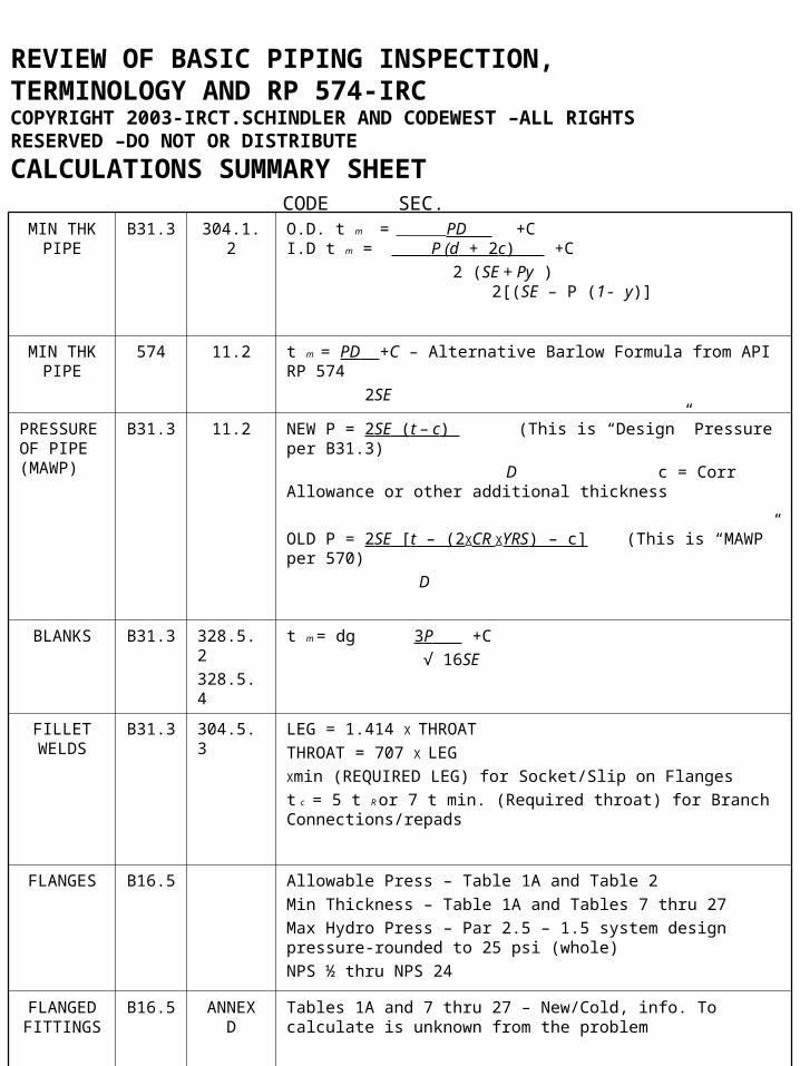
CALCULATIONS SUMMARY SHEET CODE SEC.
MIN THK PIPE
B31.3 304.1.2 O.D. t m = PD +C I.D t m = P (d + 2c) +C
2 (SE + Py ) 2[(SE – P (1- y)]
MIN THK PIPE
574 11.2 t m = PD +C – Alternative Barlow Formula from API RP 574
2SE
PRESSURE OF PIPE (MAWP)
B31.3 11.2 NEW P = 2SE (t – c) (This is “Design” Pressure per B31.3)
D c = Corr Allowance or other additional thickness
OLD P = 2SE [t – (2XCR XYRS) – c] (This is “MAWP” per 570)
D
BLANKS B31.3 328.5.2
328.5.4
t m = dg 3P +C
√ 16SE
FILLET WELDS
B31.3 304.5.3 LEG = 1.414 X THROAT
THROAT = 707 X LEG
Xmin (REQUIRED LEG) for Socket/Slip on Flanges
t c = 5 t R or 7 t min. (Required throat) for Branch Connections/repads
FLANGES B16.5 Allowable Press – Table 1A and Table 2
Min Thickness – Table 1A and Tables 7 thru 27
Max Hydro Press – Par 2.5 – 1.5 system design pressure-rounded to 25 psi (whole)
NPS ½ thru NPS 24
FLANGED FITTINGS
B16.5 ANNEX D
Tables 1A and 7 thru 27 – New/Cold, info. To calculate is unknown from the problem

FLANGED FITTINGS
B31.3
574
304.1.2
11.2
Old/corroded:
t m = 1.5 PD +C
2SE
FLANGED FITTINGS
B16.5 ANNEX D
New/Cold t = 1.5Pcd
(2S – 1.2 Pc)
Use 7000 for Stress if uknown (Calculate)
VALVES MIN THK
B31.3 345.4.2
t m = 1.5PST +C if uknown materials, us 7000 for S (Calculated)
2SE
HYDRO PRESS PIPE
B31.3 345.4.2
Min Press P T = 1.5 PST ST = Stress Value /Test Temp
S S = Stress Value / Design Temp
HYDRO PRESS FITTINGS
B16.5 Max Press = 1.5 x 100° Flange Raiting (Round to next 25 PSI)
1 min for NPS 2 and↓ and 2 min for NPS 2 ½ - 8 3 min 10↑
AIR PRESS PIPE B31.3 Castings Tables 302.33C
Piping Table A-1A THROUGH A – 1B (Add NDE See Table 302.34)
JOINT EFF/QUALITY FACTOR
B16.5 6.1.1 Castings Table 302.3.3C
Piping Table A – 1A through A – 1B (Add NDE See Table 302.34)
FLANGED FITTINGS
AREAS BELOW MINt
B 16.5 6.1.1 Diameter = 35 √dtm d = ID
Meas Thk = 75tm Area = πR ²
Dist Appart = 1.75 √dtm t = Min Wall From Charts
Tables 13 - 28
CORROSION RATES
570 7.1.1 RL = t actual – t required (LT)CR = t initial – t actual or (ST)CR = t previous – t actual
C R years
years
TENSION TESTS
SEC. IX
QW. 152
Turn Spec. Area = πR² or 7854 D²
Reduce Spec. Area = width x thickness
Tensile Strength = load/Area
Load = Area x Tensile Strength
PWHT (BRACH CONNECTIONS)
B31.3 331.1.3
MUST BE 2X THICKNESS FOR GIVEN MATERIAL IN table 331.1.1
Sketch 1 – branch thickness + fillet throat
Sketch 2 – header thickness + fillet throat
Sketch 3 – greater of branch + fillet throat or repad + fillet throat
Sketch 4 – Header thickness + repad thickness + fillet throat
Sketch 5 – same as Sketch 1
REVIEW OF BASIC PIPING INSPECTION, TERMINOLOGY AND RP 574-IRC
I. INTRODUCTION
The inspection of piping systems is a combination of many efforts. Piping system are
custom designed, with particular emphasis on the pressure, temperature and
applications in the presence of corrosive and erosive products.
This training module will discuss piping systems, components, materials, use of
drawings, codes and specifications and inspection and testing activities. This information,
in conjunction with knowledge and training such as welding inspection and NDE will
assist in preparing personnel for the API 570 examination and, hopefully for the actual
inspection of piping systems, either new or after placing in service.
The inspection of piping systems requires Inspectors who have experience and training.
These inspectors must read and interpret drawings; be able to distinguish various
components contained in a pipe system and have knowledge of procedures, codes and
document these tests when applicable to their duties. API 574 is provided to give
guidance to Inspectors on these and other subjects.
The duties of the Piping Inspector will vary depending on the requirements of the plant or
installation. All Inspectors must be trained, tested and certified in the appropriate
methods prior to performing such inspections.
1. SCOPE
The Scope of API RP 574 covers recommended inspection practices for piping, tubing,
valves, (not control valves) and fittings. Specialty items can also be inspected to RP 574.

2. REFERENCED CODES
Explanation (Not in RP 574) :
In the design and planning stages of a system or assembly, engineering assigns a
code/class designation to components based on the medium, pressure, temperature and
intended service, e.g. safety, primary cooling or heat removal, etc.
A code consists of a set of rules of procedure and standards of materials designed to
secure uniformity and to protect the public interest in matters such as building
construction, established usually by a public agency. A standard is something that is
established by a recognized authority, custom or general consent as a model or
example to be followed. These two terms have become almost interchangeable.
Both codes and standards are documents that have been established and are published
methods for designing, manufacturing, installing and testing. Each may refer to or
incorporate portions of the other in order to present a concise, understanding of what is
to be accomplished.
With the great amount of research and testing that is currently underway in the chemical
industry, many advances are being made to insure safe plant operations. These
advances will sometimes necessitate a revision or addition to a published code or
standard. These changes are reviewed and approved by committees who have members
from the industry, professional societies, government, trade associations, and
universities. Therefore, it will be necessary for you to know which codes or standards
apply to the work in which you are involved.
The issuance of codes and standards have evolved from proven engineering practices
over many years of experience. On this basis, these codes and standards have been
written to include minimum requirements for selection of material s, dimensions, design,
erection, testing and inspection to assure the safety of the plant, of its employees and
the general public.
Some of the wording contained in these codes and standards is explained as follows :
shall denotes a requirement of obligation; a recommendation implies and advisable
practice and should implies a recommendation.
Some of the standards and codes commonly encountered are issued by the American
Petroleum Institute (API), American Standards Institute (ANSI), the American Society of
Mechanical Engineers (ASME), the Instrument Society of America (ISA), the American
Society for testing and Materials (ASTM), and the American Welding Society (AWS).
These are all nationally recognized standards and codes that may apply to any piping
project. This list does not include all the different organizations issuing standards and
codes only the major ones you are likely to see.
There are three main reasons why we accept why we accept and follow codes and
standards. These are as follows :
1. Items of hardware that are made according to a standard or code are interchangeable
and are of known dimensions and characteristics.
2. Compliance with a relevant code or standard often assures performance, reliability,
quality, and provides a basis for obtaining insurance.
3. Codes are often the basis for federal, state and municipal safety regulations. Sometimes the federal government may at this own discretion publish its own regulations in the form of a code.
The use of codes and standards persists from the planning and design stage into the purchasing (procurement) of materials.
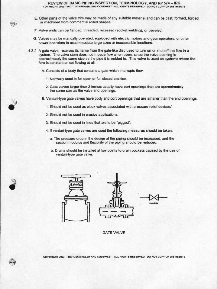
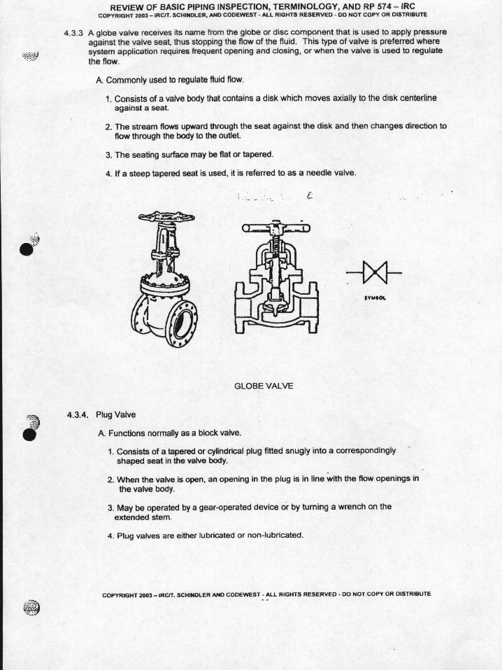
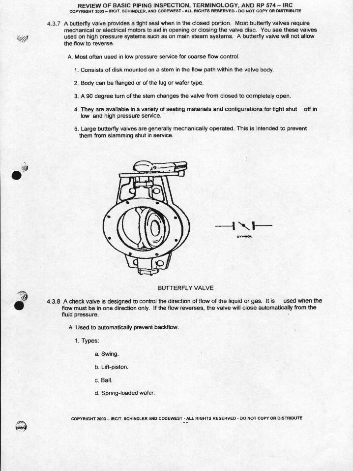
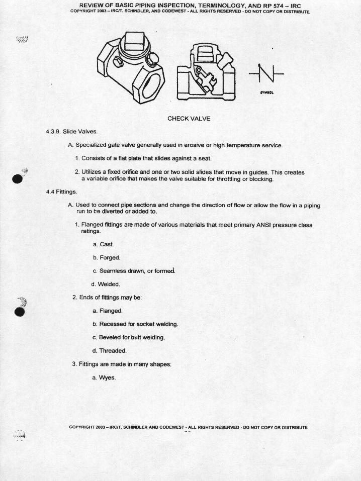
3. DEFINITIONS :
The API 570 candidate should review and be familiar with all terms and definitions shown. Some of these are redundantly identified in API 570.
4. PIPE MATERIALS AND COMPONENTS :
4.1.1 Piping – General
Carbon steel pipe is specified for in many applications because it is strong, ductile, easily
welded and machined. Also; the production costs are low. Most grades of steel pipe for code construction are procedure in accordance with ASTM or ASME specifications. The most common are ASTM A53 Grade B or ASTM A 106 Grade B Due to its tensile strength, temperature factors and lower cost.
The pipe used in plant piping systems is normally procedure in accordance with the American Society for Testing and Materials (ASTM) standards and the American Society of Mechanical Engineers (ASME) Boiler and Pressure Vessel Code. The American Society for Testing and Materials has established specifications for both ferrous and non-ferrous materials used by industry. These specifications delineate the mechanical and chemical characteristics of various grades of metal.
The ASTM/ASME specifications for some grades of carbon steel and stainless steel pipe
are shown on the following pages and are shown in RP 574. As you can see, the
specifications give a description and application, the minimum tensile strength properties
and chemical compositions of each grade listed. The ASME Code has incorporated
portions of ASTM specifications within the scope its jurisdiction.
In the United States, carbon steel piping is made to ASME B36.10M standards. Of
course, custom piping can be procedure that does not follow these rules, exactly.
Piping under 16” is normally extruded (or hot formed), reamed (or “pierced”) or drilled.
Piping larger than 16” is usually made by rolling plate (“skelp”) to size and welding the
seams. Piping thicknesses are designated as “schedules” up to 36 NPS.
For NPS 12 and smaller, the size is the nominal i.d. of the pipe for standard wall. For
NPS 14 and over, size is the actual o.d. of the pipe.
Tolerances for piping depend on the type of material, and size and method of
manufacture. For example :
Seamless carbon steel piping - 12.5% under tolerance on published thickness
Welded carbon steel piping – 0.1” under tolerance on published thickness
Cast piping - + 1/16”, -0” under tolerance on published thickness.
Other tolerances for weight, length, etc. are given in the pipe charts provided on the
following pages :


4.5.5 Cast Iron pipe joints – can be flanged, packed sleeve, hub-and spigot-end, or hub-
and –plain-end, or bell-and –spigot, or bell-and-plain –end type. Push-on joints
with rubber or synthetic ring gasket are available. Clamped joints are also used.
Threaded joints are seldom used for cast iron.
4.5.6 Tubing Joints – can be joined by welding, soldering, brazing or using flared or
compression fittings
4.5.7 Special Joints – Proprietary joints area available that incorporate unique gaskets,
clamps and bolting arrangements. These designs offer advantages over
conventional joints in certain services but usually have lower pressure and
temperature movements.
Section 5 – Reasons for Inspection
5.1 General
A. The primary purpose of inspection :
1. Ensure safety
2. Achieve the desired quality assurance
3. Ensure reliability
B. Achieving the above requires information about the physical condition of
equipment and the rate and causes of its deterioration.
1. With the above information the user may :
a. Recommend necessary repairs
b. Predict future repairs and replacements
c. Act to prevent or retard further deterioration
2. This will result in reduced maintenance costs and more reliable and efficient
operations

5.2 Safety
A. Leaks or failures in a piping system may be minor or major
1. Leaks and minor inconvenience
2. Source or fire or explosion
3. Materials carried in piping systems – acids, alkali’s, hydrocarbons, chemicals,
toxic by-products.
4. Adequate inspection is a prerequisite for maintaining piping in a safe,
operable condition
B. In general leakage normally occurs at flanged joints in a piping system.
1. Controlled bolt-up procedures
a. Bolt-tensioning devices.
b. Ultrasonic tightening methods
2. Use of hardened washers or Beeville washers
5.3 Reliability and Efficient Operation
A. Thorough inspection, analysis and use of detailed historical records
B. Attain reliability, efficient operation and optimum on-stream service.
5.4 Regulatory Requirements
A. Check requirements of Federal, State and Local statutes and regulations.
B. Regulatory requirements usually cover only those conditions that affect safety.
Section 6 – Inspecting for Deterioration in Piping
6.1 General : Piping can deteriorate by several means :
• Internal or external corrosion• Internal erosion
6.2 Most frequent reason for replacing piping is thinning due to corrosion. This necessitates that an effective corrosion monitoring program be developed and implemented.
• Piping must be risk prioritized per API 570• TML’s (Thickness Measurement Locations) designated and recorded• Factors to consider for a corrosion monitoring program :
1. risk classification
2. categorize pipe into circuits for similar corrosion
3. identify susceptible locations for corrosion
4. accessibility to monitor TML’s
6.2.1 When determining what (or how far) a piping circuit should extend, the following should be considered:
• Metallurgy• Contents• Velocity• Temperature• Pressure• Injection points• Mixing of steams• External conditions• Areas of no/low flow
Dividing piping into circuits is primarily done to allow management of the enormous
amounts of data that are generated.

6.2.2 Additional TML’s should be assigned at areas of accelerated corrosion such as
mixing tees, elbow reducers, control valves and restrictor orifices or metering
orifices.
6.2.3 Piping risk classifications are based on :• Toxicity• Volatility• Combustibility• Location in the plant• Experience and history
All piping within the scope of 570 must be risk-classified
6.2.4 The Inspector should always taken into account accessibility when selecting
areas for TML’s.
6.3 This entire section is, essentially a verbatim repeat of what is currently located in
Section 3 of API 570. Eventually, it is thought that Section 3 in API 570 will be
deleted and this is the reason why put this in RP 574 at this time. This section will
be thoroughly reviewed in the API 570 module.
EDITORS NOTE : This section has really never belonged in API 570, and as such, this
will be a good “clean-up” of 570 when, and if, this change occurs.
Section 7 – Frequency and Time of Inspection.
7.1 General
A. Frequency and thoroughness
1. Often and complete where deterioration is extreme
2. Seldom and cursory in non-corrosive service.
B. Frequency determined by:
1. The consequence of failure. (piping classifications)
2. The degree of risk. (like hood and consequence of failure – RBI)

3. The amount of corrosion allowance remaining.
4. The historical data available
5. Regulatory requirements
C. Some inspections can and should be made while the equipment is operating.
D. Other inspections must be made while the equipment is not operating
7.2 Inspection While Equipment is Operating
A. On-stream UT inspections and Radiographs to monitor wall thickness
B. Review historical records – determine pipe sections that may be approaching
minimum and may have to be replaced at a scheduled shutdowns.
C. Reduce downtime by :
1. Extending process runs and preventing some unscheduled shutdowns
2. Permitting fabrication of replacement piping before a shutdown.
3. Eliminating unnecessary work and reducing personnel requirements
4. Aiding maintenance planning to reduce surges in work load.
D. Look for leaks – determine seriousness and take corrective action
E. Inspect pipe supports and pipe anchors
F. Inspect for external corrosion – Piping, supports and spring hangers.
7.3 Safety Precautions and Preparatory Work
Section 8 – Safety precautions and Preparatory Work
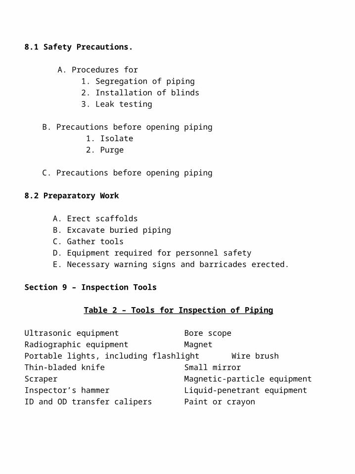
8.1 Safety Precautions.
A. Procedures for
1. Segregation of piping
2. Installation of blinds
3. Leak testing
B. Precautions before opening piping
1. Isolate
2. Purge
C. Precautions before opening piping
8.2 Preparatory Work
A. Erect scaffolds
B. Excavate buried piping
C. Gather tools
D. Equipment required for personnel safety
E. Necessary warning signs and barricades erected.
Section 9 – Inspection Tools
Table 2 – Tools for Inspection of Piping
Ultrasonic equipment Bore scope
Radiographic equipment Magnet
Portable lights, including flashlight Wire brush
Thin-bladed knife Small mirror
Scraper Magnetic-particle equipment
Inspector’s hammer Liquid-penetrant equipment
ID and OD transfer calipers Paint or crayon
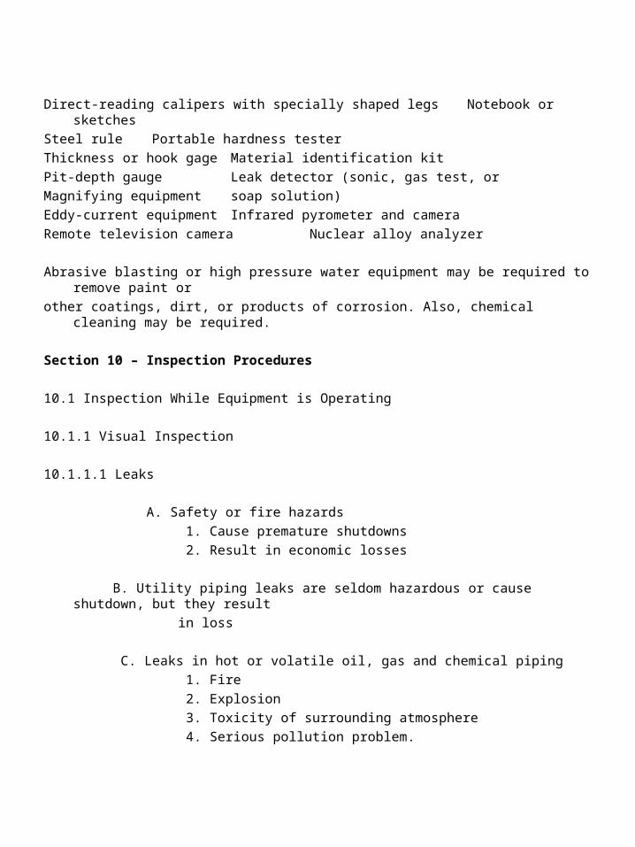
Direct-reading calipers with specially shaped legs Notebook or sketches
Steel rule Portable hardness tester
Thickness or hook gage Material identification kit
Pit-depth gauge Leak detector (sonic, gas test, or
Magnifying equipment soap solution)
Eddy-current equipment Infrared pyrometer and camera
Remote television camera Nuclear alloy analyzer
Abrasive blasting or high pressure water equipment may be required to remove paint or
other coatings, dirt, or products of corrosion. Also, chemical cleaning may be required.
Section 10 – Inspection Procedures
10.1 Inspection While Equipment is Operating
10.1.1 Visual Inspection
10.1.1.1 Leaks
A. Safety or fire hazards
1. Cause premature shutdowns
2. Result in economic losses
B. Utility piping leaks are seldom hazardous or cause shutdown, but they result
in loss
C. Leaks in hot or volatile oil, gas and chemical piping
1. Fire
2. Explosion
3. Toxicity of surrounding atmosphere
4. Serious pollution problem.

D. Frequent visual inspections should be made for leaks. 1. Flanged joints 2. Packing glands 3. Bonnets of valves 4. Expansion joints
E. Stop leaks 1. Tighten flange bolts 2. Tighten packing glands 3. Temporary repairs while in service. a. Box in. b. Stop leak (pump in material that acts as a gasket, etc.) c. Full circumference wrap.
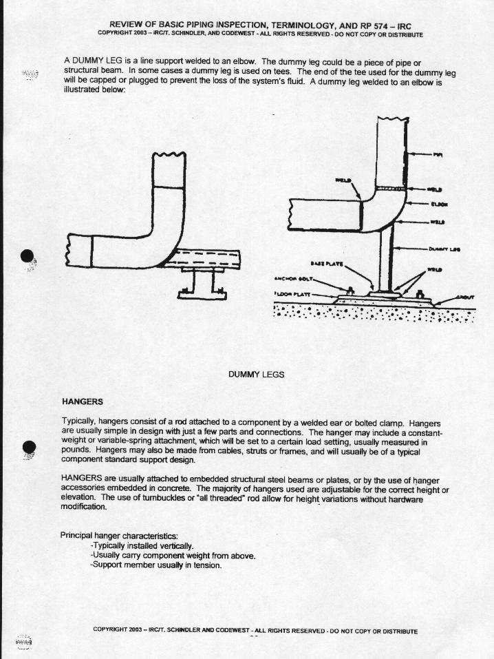
10.1.1.2 Misalignment. A. Pipe off its support B. Deformation of a vessel wall at a pipe attachment C. Pipe supports out of plumb D. Excessive replacement or repair of pump and compressor bearings E. Shifting of base plates or foundation breaking F. Cracks in connecting flanges or the cases of pumps or turbines where pipe attached. G. Expansion joints that are not performing properly.
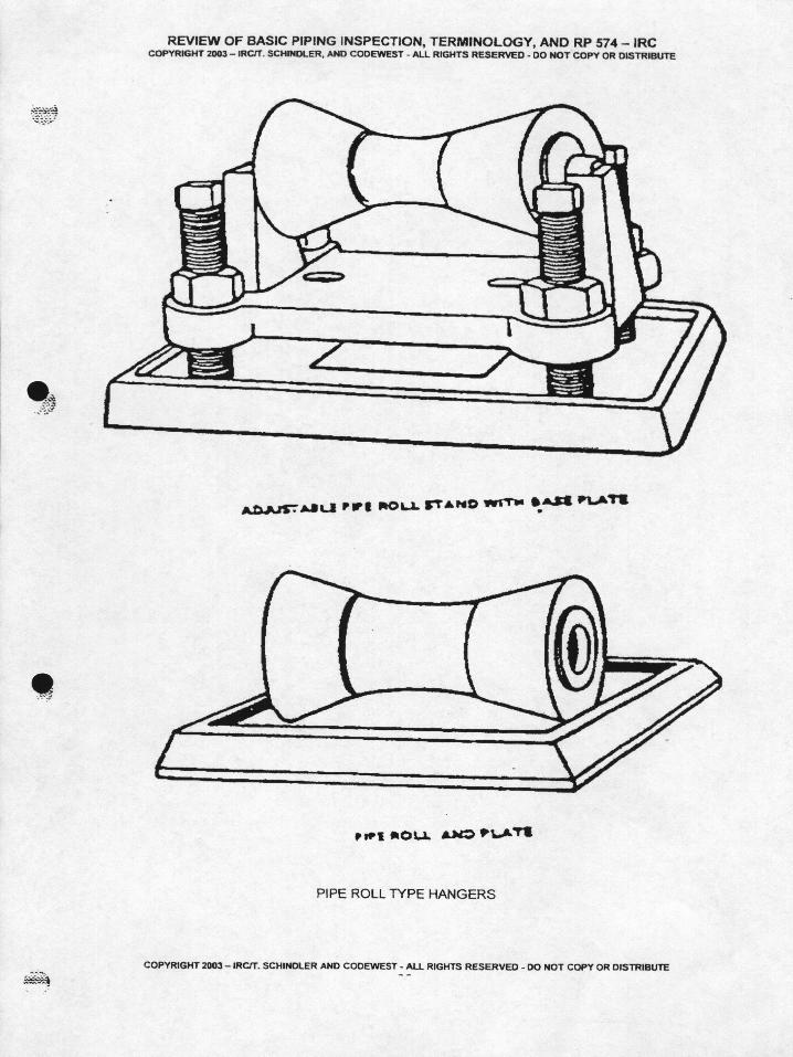
10.1.1.3 Supports A. Shoes, Hangers 9chains or springs), and braces. Inspect visually: 1. Deterioration of protective coatings or fireproofing 2. Evidence of corrosion 3. Distortion 4. General physical damage 5. Movement or deterioration of concrete footings 6. Failure or loosening of foundation bolts 7. Insecure attachment of brackets and beams to the support.
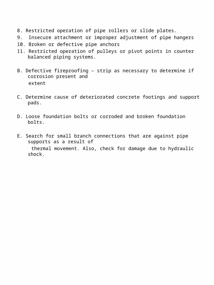
8. Restricted operation of pipe rollers or slide plates.
9. Insecure attachment or improper adjustment of pipe hangers
10. Broken or defective pipe anchors
11. Restricted operation of pulleys or pivot points in counter balanced piping systems.
B. Defective fireproofing – strip as necessary to determine if corrosion present and
extent
C. Determine cause of deteriorated concrete footings and support pads.
D. Loose foundation bolts or corroded and broken foundation bolts.
E. Search for small branch connections that are against pipe supports as a result of
thermal movement. Also, check for damage due to hydraulic shock.


10.1.1.4 Vibration
A. Inspect for cracks where vibration or swaying has been observed. 1. Problems at small connections with heavy valves attached 2. Problems at small lines that are tied down to a larger line and forced to move with
the larger line. 10.1.1.5 External Corrosion. A. Moisture getting through at defects in protective coatings. 1. Check small connections, such as bleed lines and gauge connections – difficult to
obtain a good seal in the insulation. 2. Remove enough insulation to get a good check
B. Sweating linesC. Losses in thickness can be determined by comparing the pipe diameter at the corroded area with the original pipe diameter. Pits diameter. Pits can be checked with a pit gage.D. Check bolting
10.1.1.6 Accumulations of Corrosive Liquids – Spilled liquid onto the ground may involve chemical analysis
10.1.1.7 Hot Spots – May cause bulging and may be used by failed internal insulation, which should be reported. Can be detected by a red glow, or measured using thermograph, pyrometer, or temp stik may be temporarily cooled by water or steam, or air until the hot spot can be repaired, if reviewed by a qualified Piping Engineer.
10.1.2 Thickness Measurements
10.1.2.1 Ultrasonic Inspection.
A. Used widely for thickness measurements and is “standard equipment”.
Advantages :
a. portability
b. low cost
c. minimum training
Disadvantages :
a. Not explosion proof
b. Temperatures affect transducers (approx. 1,000°F max. )
c. Isolated pits are difficult are difficult to find – Dual transducers can detect pits
as small as 1/8”. “A” scan meters should be used on highly corroded
surfaces.
d. Above 200°F readings are normally higher. Usually 1% at 300°F to 5% at
700°F. Thickness corrections should be tabulated and established for heated
and unheated samples.
EXAMPLE : 1” thick at 70°F will be approximately 1.05” thick at 700°F
B. Good for flaw detection in welds (cracks, weld porosity, LP, etc.) – special
training of operators required.
10.1.2.2 Radiographic Inspection
A. Advantages 1. Pipe insulation can remain intact 2. The metal temperature of the line has little bearing on the quality of the radiograph
– moving liquid in a line can prevent quality pictures. 3. Radiographs of small pipe connections, such as nipples and couplings, can be
examined for thread contact, corrosion and weld quality. 4. film negatives provide a permanent visual record of the condition of the piping at the
time of the radiograph. 5. The position of internal parts of valves can be observed. 6. Radiographic equipment is easily maneuverable in a plant. 7. Isotope radiography is not an ignition source in the presence of hydrocarbons.
B. Disadvantages 1. Special precautions must be taken because of radioactivity 2. Higher cost 3. Jurisdictions involved because of radioactivity 4. Must guard against interference with existing process-unit control systems.
10.1.3 Other on-stream Inspections• Halogen Leak Detectors• Neutron RT• VT for CUI• Neutron Backscatter• Magnetic Induction• Thermograph• Real Time RT Note: Visual inspection of TML’s will usually not provide a good evaluation of CUI.
10.2 Inspection While Equipment is Shut Down
10.2.1 Visual Inspection
10.2.1.1 Corrosion, Erosion and fouling
A. Open pipe at various places by removing a valve, or fitting or by springing the
pipe apart at flanges – check internally with :
1. Flashlight
2. Extension or light
3. Bore scope or flexi scope
4. Mirror
5. TV camera
6. Supplement with radiographs
B. Note fouling observed to determine if cleaning required.
10.2.1.2 Cracks
A. Welds are most susceptible
1. Tack welds
2. Heat affected zones.
3. arc strikers (especially true in Amine equipment)
B. Areas of restraint or excessive strain
C. Clean surfaces to be inspected.
D. Use MT, PT, UT, VT
10.2.1.3 Gasket Faces of Flanges.
A. Visually inspect for corrosion and defects such as scratches, cuts and gouges.
B. Use straight edge for check for warping
C. Check grooves of ring joint flanges for defects and cracks.
10.2.1.4 Valves
A. Dismantle at intervals and check internals and body thickness.
B. Check gate valves for thickness between the seats – turbulence. Check wedge guides
for corrosion and erosions.
C. Stem and threads on the stem and in the bonnet of all valves should be examined for
corrosion that might cause failure.
D. Check shaft and hinges and all other parts of check valves.
E. Quarter turn valves should be inspected for ease of operation and the ability to open
and close complete. Check seating surfaces.
F. Hydro test or pneumatically test valves for tightness after re-assembly.
10.2.1.5 Joints
10.2.1.5.1 Flanged Joints
A. When opened, they should be visually inspected for cracks and metal loss caused by
corrosion and erosion.
B. Check flange bolts.
1. Stretching and corrosion
2. Check for cracks in thread area.3. Check for bent bolts4. Check for proper specifications of bolt5. Check for proper specifications of gasket material
6. Replace deformed flanges.
10.2.1.2 Welded Joints
A. Cracks and corrosion/erosion 1. Check for hardness where environment cracking service may occur.
B. Pitting corrosion
C. Welded joints in carbon steel and carbon-Molly steel operating at temperatures of 800 degrees F. or over may be subject to graphitization. A sample should be taken from a welded joint, and examined metallurgic ally for evidence of graphitization.
10.2.1.5.3 Threaded joints.
A. Leaks may be caused by : 1. Improper assembly 2. loose threads 3. Corrosion 4. Poor fabrication 5. Cross threading 6. dirty threads 7. Lack of thread lubricant or the use of the wrong lubricant. CAUTION : A leaking threaded joint should not be tightened while the system is in
services under pressure. An undetected crack in a thread root might fail and cause a release of product with serious consequences.
10.2.1.5.4 Clamped Joints
A. Depends on machined surface for tightness (Gray loc flanges)
1. Depends on machined surface for tightness (Gray loc flanges)
B. If leak occurs, tighten clamp. If leak cannot be stopped by tightening clamp, shut
system down and dismantle the joint to determine cause of leak.
10.2.1.6 Misalignment
A. Causes of misalignment
1. Inadequate provision for expansion
2. broken or defective anchors or guides
3. Excessive friction on sliding saddles, indicating a lack of lubrication
4. Broken rollers or rollers that cannot turn because of corrosion or lack of
lubrication.
5. Broken or improperly adjusted hangers
6. Hangers that are too short and thus limit movement or cause lifting of the
piping
7. Excessive operating temperature
B. Consequences of misalignment can be serious
1. Pumps thrown out of alignment
2. Compressors thrown out of alignment
10.2.1.7 Vibration
A. Check points of abrasion
B. Check for external wear
C. Check for cracks
D. Supplement visual inspection with : RT, UT, MT, PT
E. Correct excess vibration
10.2.1.8 Hot Spots
A. Inspect internal insulation
B. Check cause of hot spot
C. Check metal in area of hot spot
1. Oxidation
2. Scaling
3. Check for creep by measuring pipe OD for increase.
10.2.2 Thickness Measurements.
A. Measurement methods
1. Caliper at open flanges
2. UT
3. RT
B. Measure piping that was not available during on-stream.
C. Check small connections (such as nipples)
1. Radiograph
2. Hammer test.
10.2.3 Pressure Tests.
A. Can function as a leakage or tightness test before a unit is place back on stream
1. A pressure test in most cases is a leak test
2. Reveal gross errors in design or fabrication
3. Test should be in accordance with API 570, which references B31.3
B. Piping systems subject to pressure testing include the following :
1. Underground lines and other inaccessible piping
2. Water and other non- hazardous utility lines
3. long oil-transfer lines in areas where a leak or spill would not be hazardous to
personnel or harmful to the environment.
4. Complicated manifold systems
5. Small piping and tubing systems
6. All systems, after a chemical cleaning operation.
C. The rules for pressure testing equipment are generally the same as those for piping.
When vessels of process units are pressure tested, the main lines connected to the
vessels are often tested at the same time.
D. Completely isolate any systems being tested – Use blinds rated same as flanges
1. Be sure to isolate or remove or make sure the test will not damage : Gauge glasses, pressure gauges, control valves, pressure relief valves, instrument lines and similar connecting lines.
2. Expansion joints must be protected against excessive pressure or isolated during testing .
E. Follow jurisdictional rules.
F. During liquid testing, air must be expelled from the piping through vents provided at
high points – remove compressible medium.
G. Do not over pressure system. Use calibrated pressure gages properly located. Avoid
sudden rises in pressure.
H. Pressure supply :
1. Pump
2. Bottled inert gas – keep quantity small
I. Always use a relief valve when testing
J. Mediums used for testing
1. water with or without an inhibitor, freezing – point depressant , or wetting agent.
2. Liquid products normally carried in the system , if they of not toxic or likely to cause a fire in the event of a leak or failure.
3. Steam
4. Air, carbon dioxide, nitrogen, helium or another inert gas
K. Water
1. Considered best because it is inert and will not harm environment unless it is contaminated by product present in the lines. (if this occurs, the system must be drained to an environmentally safe system for treatment.)
2. Corrosion caused by salt in water
3. Stress corrosion cracking because of high chloride content

4. Problems because of freezing
5. Requires warming in cold weather – may be done with steam.
L. Steam
1. Should not exceed operating pressure
2. Follow pneumatic testing precautions noted in B31.3
M. Pneumatic tests.
1. Preferred medium is inert gas
2. Follow pneumatic testing precautions noted in B31.3
N. Use “drop test” on underground systems – use pressure recorders
10.2.4 Hammer Testing.
A. Do not use :
1. On lines under pressure
2. Cast iron.
3. Stress relieved lines in caustic and corrosive service
4. On copper tubing, brass piping , or other piping made from soft materials
5. On glass lined piping
6. On cement, refractory, or other internally coated piping
7. Alloy piping where stress corrosion cracking can occur.
B. Used to extend the scope of inspection to detect the presence of unexpected
thin sections
10.2.5 Inspection of Piping Welds – Inspect for weld quality according to the
recommendations given in ASME B31.3.
10.3 Inspection of Buried Piping
10.3.1 Types and Methods of Inspection and Testing
10.3.1.1 Above ground Surveillance – for softening, discoloration, puddles, etc.
10.3.1.2 Close – Internal Potential Survey – used to locate corrosion cells, anodes, stray
currents, coating problems. Typically performed at 2.5, 5, 10 or 20 feet.
10.3.1.3 Holiday Pipe Coating Survey locates defects in coating or exposed pipe
10.3.1.4 Soil Resistively Testing – Classifies soil corrosivity. Lower resistively equals
more corrosion, higher resistively, usually means less corrosion. 3 methods
normally used, which used, which measures voltage drop across a known
amount of soil
1. Wenner 4-pin method (resistivity = 191.5 x d x R) Where 191.5 is a constant.
d = distance in feet between pins, and R = resistance factor of the voltage
drop across the two inner pins, divided by the current flow between the
two outer pins.
2. Soil bar (a – c bridge)
3. Soil box
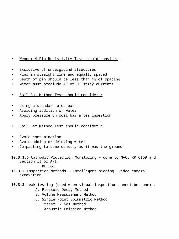
• Wenner 4 Pin Resistivity Test should consider :
• Exclusive of underground structures• Pins in straight line and equally spaced • Depth of pin should be less than 4% of spacing• Meter must preclude AC or DC stray currents
• Soil Bar Method Test should consider :
• Using a standard prod bar• Avoiding addition of water• Apply pressure on soil bar after insertion
• Soil Bar Method Test should consider :
• Avoid contamination• Avoid adding or deleting water• Compacting to same density as it was the ground
10.3.1.5 Cathodic Protection Monitoring – done to NACE RP 0169 and Section II or API RP 65110.3.2 Inspection Methods – Intelligent pigging, video camera, excavation
10.3.3 Leak testing (used when visual inspection cannot be done) : A. Pressure Decay Method B. Volume Measurement Method C. Single Point Volumetric Method D. Tracer - Gas Method E. Acoustic Emission Method
10.4 Inspection of New Construction
10.4.1 General A. Must meet Requirements of B31.3 as a minimum B. Procedures used to inspect piping systems while equipment is shut down are adaptable to the inspection of new construction. 1. Thickness measurements 2. Inspection for cracks 3. Inspection of gasket faces 4. Inspection of valves, and joints.
5. Inspection of welds 6. Inspection of welds 7. Pressure testing
B. Extent of inspection during fabrication and installation depends largely on the severity of the service & the quality of the workmanship, and it should be part
of the design the design.
10.4.2 Inspection of Materials A. Check for conformance with codes and specifications B. Radiograph of welds is especially important during new construction C. PT and MT may also be required on welds.
10.4.3 Deviations A. Special reviews may be required to determine whether piping deviates enough from standards or specifications to cause rejection B. Any deviations accepted should be thoroughly and properly documented for future

Section 11 – Determination of Retirement Thickness.
11.1 Piping
A. Refer to B31.3
B. Take into account :
1. Corrosion.
2. Threads – crevice corrosion
3. Stresses caused by mechanical loading, hydraulic surges, thermal expansion
and other conditions.
C. Additional thickness is usually required when the items in “B” is taken into
account
D. Additional thickness according to ASME B31.3
E. Manufacturing tolerance must also be taken into account
F. May use Barlow Equation if thickness is less than D/6 and P/SE is not greater
than 0.385.
t = PD t = pressure design thickness for internal pressure in inches
2SE P = internal design gage pressure of the pipe in psi.
D = outside diameter of pipe in inches.
S = allowable unit stress at the design temperature in psi.
E = longitudinal joint efficiency.
The manufacturing tolerance and any applicable thread or groove depth plus corrosion or
erosion must be considered. Additional thickness must be added as necessary when
taking into account the previous.

G. The Barlow Equation gives results that are practically equivalent to those obtained by
the more elaborate formula except in cases involving high pressures where thick-
walled tubing is required. Metallic pipe for which t>D/6 or P/SE>0.385.
H. ASME B31.3 contains the allowable unit stresses to be used in the formulas.
I. At low pressures and temperatures, the thickness determined by the Barlow Equation
may be so small that the pipe would have insufficient structural strength. For this
reason, an absolute minimum thickness to prevent sag, buckling and collapse at
supports should be determined for each size of pipe. The pipe wall should not be
permitted to deteriorate below this minimum thickness regardless of the results
obtained by the formula.
11.2 Valves and Flanged Fittings.
A. ASME B16.34 establishes the minimum valve wall thickness at 1.5 times the
thickness (1.35 times for Class 4500) of a simple cylinder designed for 7000 psi
and subject to an internal pressure equal to the pressure rating class for valve
Classes 150 to 2500. The actual valve wall thickness requirements given in Table
3 of ASME B16.34 are approximately 0.1 inch thicker than the calculated values.
Valves furnished in accordance with API Standard 600 have thickness
requirements for corrosion and erosion in addition to those given in ASME
B16.34.
B. If corrosion or erosion is expected, reference thicknesses should be taken when
the valves are installed so that the corrosion rate and metal loss can be
determined.
C. The formula for calculating the retirement thickness of pipe can be adapted for valves
and flanged fittings by using the factor of 1.5 and the allowable stress for material
specified in ASME B31.3. In some cases, the calculated thickness will be impractical
from a structural standpoint; therefore minimum thicknesses should be established.
t = 1.5PD + Corrosion Allowance
2SE
D. Above calculations do not apply to welded fittings. The calculations for pipe can be
applied to welded fittings using appropriate corrections for shape.
Section 12 – Records.
12.1 General
A. Accurate records make possible an evaluation of service life on any piping,
valve, or fitting.
B. When properly organized, records form a permanent record form which corrosion
rates and probable replacement or repair intervals can be determined.
C. A computer program can be used for complete evaluation
1. Determine next inspection date
2. Determine piping replacement date
D. Records should contain :
1. Original thickness measurements
2. The specifications and strength levels of the materials used
3. Original thickness measurements
4. Locations and dates of all subsequent thickness measurements
5. The calculated retirement thickness

E. Suitable forms must be developed and used that will furnish a chronological picture of
the piping.
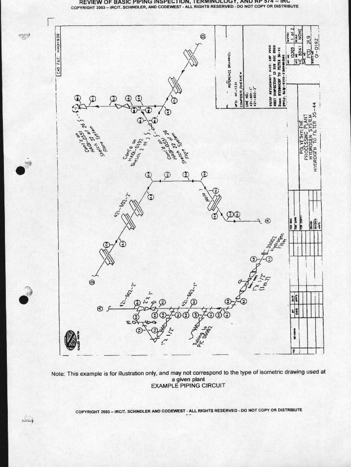
12.2 Sketches.
A. Isometric or oblique drawings provide a means of recording the size of piping
lines and locations at which thickness measurements are taken. They may be
original construction drawings or separate sketches made by Inspectors.
B. Sketches have the following important functions :
1. Identify particular piping systems in terms of location, size, material
specification, general process flow and service condition.
2. Inform the mechanical department of points to be opened for visual inspection
and parts that require replacement or repair.
3. Serve as field data sheets on which can be recorded the locations of
thickness measurements, serious corrosion and sections requiring immediate
replacement.
4. Assist at future inspections in determining locations that urgently require
examination.
12.3 Numbering Systems – The use of a coding system that identifies the process unit, the piping system, and the individual items composing the system may be advisable

12.4 thickness Data – A record of thickness readings obtained during inspections provides a means of arriving at corrosion or erosion rates and expected material life. Some use computerized record systems for this purpose. Data may be shown on isometric sketches or presented in tabulated from.
12.5 Review of Records – Records should be reviewed after inspections to schedule the next I inspection. High corrosion rate areas, retirement thickness areas and suspect areas should be considered. Predicting repairs/replacements at the next down should be documented and submitted to maintenance for planning purposes.
BASIC PIPING INSPECTION, TERMINOLOGY AND RP 574 PRACTICE
QUESTIONSQUESTIONS 1-95 ARE CLOSED BOOK
1. API Recommended Practice 574, Inspection of Piping, Tubing Valves and Fittings,
does not cover :
a. control valves
b. piping smaller than 2” NPS
c. tubing smaller than 1.5” diameter
d. fitting smaller than 2” NPS
2. The refining industry generally uses what type piping for severe service?
a. brass
b. cast
c. seamless
d. longitudinal seam welded
3. Piping made by rolling plates to size and welding the seams is larger than
inches outside diameter.
a. 10
b. 16
c. 14
d. 12
4. Steel and alloy piping are manufactured to standard dimensions in nominal pipe sizes
up to inches.
a. 24
b. 36
c. 48
d. 50

5. Steel and alloy piping are also manufactured to standard thicknesses designated as
schedules in nominal pipe sizes up to inches.
a. 24
b. 36
c. 48
d. 50
6. The actual thickness of wrought piping may vary from its nominal thickness by a
manufacturing under tolerance of as much as percent.
a. 12.5
b. 12.0
c. 10.0
d. 10.5
7. Cast piping has thickness tolerance of + inch and - inch.
a. 1/16, 0
b. 1/16, 1/16
c. 1/32, 1/32
d. 3/64, 0
8. For all nominal pipe sizes of inches and smaller, the refers to the nominal
inside diameter.
a. 10
b. 12
c. 14
d. 16
9. Under tolerance of welded pipe often used in refinery service is inch.
a. 0.125
b. 0.050
c. 0.010
d. 0.005
10. For what service is cast iron piping normally used
a. No hazardous service, such as lube oils
b. No hazardous service, such as lube as water
c. Corrosive service, such as acids
d. No corrosive service, such as low temperature caustic.
11. Tubing is generally seamlessly drawn, but it may be welded. Its stated size is its
actual :
a. outside radius
b. inside diameter
c. outside diameter
d. inside radius
12. There are many type valves. Which is the incorrect valve type listed below?
a. style valve
b. gate valve
c. check valve
d. globe valve
13. What type valve is normally used in a fully open or fully closed position?
a. gate
b. globe
c. slide
d. plug
14. What type valves have body and port openings that are smaller than the valves’ end
opening.
a. Borda tube gate valves
b. Reduced-port gate valves
c. Weir gate valves
d. Sluice gate valves
15. What type of gate valve should not be used as block valves associated with pressure
relief devices?
a. Sluice gate valves
b. Weir gate valves
c. Weir tube gate valves
d. reduced-port gate valves
16. What is a globe valve used for?
a. It is normally used as block valve
b. It is commonly used to regulate fluid flow
c. It is ordinarily used to measure pressure drop
d. It is frequently used in place of a slide valve.
17. A plug valve consists ;
a. of a slide or slides that operate perpendicularly to the flow and move on rail guides
to interrupt flow.
b. of a ball with a hole in it that fits into the valve body and interrupts the flow of
material
c. of a circular gate that operates in and out in the body to interrupt flow.
d. of a tapered or cylindrical truncated cone with a slot that is fitted into a
correspondingly shaped seat.
18. What type of valve depends upon a spherical type gate has a hole in it rotated to
open or close it?
a.diaphram valve
b. plug valve
c. globe valve
d. ball valve
19. What are check valves normally used for?
a. They are generally used in erosive or high-temperature services
b. They are used to automatically prevent backflow
c. They are commonly used to regulate fluid flow
d. They are used for conditions that require quick on/off or bubble tight service.
20. What are slide valves generally used for?
a. They are used to automatically prevent backflow.
b. They are used for conditions that require quick on/off or bubble tight service
c. They are generally used in erosive or high
d. They are commonly used to regulate fluid flow.

21. What type of joint listed below would you NOT use in a 300 psi pipe system?
a. lap-joint flanged
b. welded
c. bell-and-spigot
d. weld-neck flanged
22. What type of pipe joint is generally limited to piping in non-critical service and has a
nominal size of 2 inches or smaller.
a. flanged joint
b. threaded joint
c. socket-weld joint
d. butt-welded joint
23. Socket-welded joints are usually used in nominal pipe sizes of or
smaller.
a. 4”
b. 3”
c. 2.5”
d. 2”
24. Which of the joints listed is the most common found in the petroleum industry?
a. compression joints
b. butt-welded joints
c. bell-and-spigot joints
d. sleeve joints
25. The primary purpose of piping inspection is to :
a. satisfy the requirements of jurisdictional regulations
b. achieve at the lowest cost, piping that is reliable and has the desired quality
c. ensure plant safety and reliability; also achieve desired quality assurance
d. produce a piping system that meets minimum design and serviceability
requirements
26. Adequate inspection is a prerequisite for maintaining piping :
a. in a leak free condition
b. satisfactory to the owner-user
c. in a satisfactory operating condition
d. in a safe, operable condition.
27. OSHA 1910.119 mandates that :
a. piping be inspected to a code or standard such as API 570
b. owner/users adopt API 570
c. water piping be inspected the same as chemical piping
d. the owner/ user immediately shut down corroded piping systems.
28. Regulatory requirements usually cover only those conditions that affect :
a. pollution
b. operations
c. safety
d. maintenance

29. The single most frequent reason for replacing piping is : a. an over-zealous Inspector b. in-service cracking c. H2S deterioration and erosion d. thinning due to corrosion
30. On piping that is operating, they key to effective monitoring of piping corrosion is identifying and establishing . a. L.O.L. ’s b. J.L.G. ’s c. T.M.L. ’s d. C.U.I. ‘s
31. You are asked to recommend a method for determining the thickness of a pipe that has 1.5” of insulation, with a vapor barrier and aluminum jacketing on it. What is one of the best ways to get the wall thickness without stripping the jacketing and insulation? a. UT b. RT c. ET d. AE
32. Leaks in piping systems are most easily detected : a. by the inspector when the system is down for inspection and test b. by acoustic instruments that can pick up high frequency sounds produced by leaks. c. while the piping is being tested d. while the equipment is operating and should be looked for continuously

33. Three problems can occur when tightening bolts to correct leaking flanges in-service.
Which of the below is not one of these problems?
a. bolt interactions
b. yielding due to overload
c. flange deflection
d. none of the above
34. Which one of the following is not a factor for consideration when establishing
corrosion monitoring programs?
a. accessibility
b. circuitization
c. transducer diameter
d. risk classification
35. A greater loss in metal thickness will usually be observed near a restriction or change
in direction in a pipe line. What usually causes this?
a. The effects of turbulence or velocity
b. The effects of stagnation or fretting
c. The effects of corrosion or declination
d. The effects of oxidation or waning.
36. What type of problem would you expect to find in catalyst, flue-gas, and slurry piping
on a Fluid Catalytic Unit.
a. embitterment
b. cracking
c. corrosion
d. erosion
37. Stainless steel such as type 304 18 Chr. -8 Ni in the presence of temperature above 100 degrees F. may crack because of the presence of : a. nitrates b. sulfides c. chlorides d. dissolved oxygen
38. A 2” diameter line is injecting a product into an eight inch diameter pipe. What type of deterioration would you except to take place? a. accelerated corrosion or erosion b. long term corrosion. c. chloride cracking d. dissolved oxygen pitting
39. An inspector is checking a piping system that has had problems with isolated corrosion at or near the welds of piping shoes. Without knowing what knowing what product is in the, what would be the best answer below for the problem? a. The shoes are at high stress points and thus leaks occur. b. The welds of the shoes to the pipe were too large c. The welds of the shoes to the pipe burned nearly through the pipe. d. The shoes are acting as cooling fins and causing localized temperature differences.
40. What type of problem of problem would you except in piping containing Amine? a. dissolved oxygen cracking b. stress corrosion cracking c. galvanic corrosion d. crevice corrosion

41. What area do you consider to be of most concern when inspecting a piping system?
a. Underneath insulation on lines operating at temperatures above 200 degrees F.
b. In a straight run pipe containing motor oil
c. At and/or downstream of a chemical injection point
d. Underneath insulation on lines operating below 25 degrees F.
42. Leaks in utility piping (water, steam, etc.) are :
a. only of minor concern and may be disregarded
b. always dangerous but losses are negligible
c. seldom hazardous but they do result in losses
d. usually hazardous and losses result
43. Where do many (maybe the majority) of leaks occur in pipelines?
a. straight runs of piping
b. flanges or packing glands
c. changes of direction of piping
d. downstream of injection points.
44. The prompt repair of will often prevent serious corrosion or erosion
of gasket surfaces or packing glands.
a. supports
b. leaks
c. guides
d. welds

45. The deformation of a vessel wall in the vicinity of a pipe attachment; expansion joints
that are not performing properly; a pipe dislodged from its support; etc. are evidence
of :
a. misalignment
b. leaks
c. weld problems
d. drips
46. Spring hanger loadings should be checked under :
a. elevated temperature conditions
b. both cold and hot conditions
c. sub-zero temperature conditions
d. ambient temperature conditions
47. An inspector finds concrete fireproofing around a structural steel column with
openings (cracks). The inspector suspects that water may be entering. What should
the inspector do?
a. The inspector should ask his supervisor what he should do.
b. All the fireproofing should be stripped from the column
c. Enough fireproofing should be removed to determine the next of the problem
d. No action should be taken.
48. If a steel column in a pipe support rack is corroded. What should the inspector do?
a. Have the corrosion products cleaned off and have the column painted
b. No action is required
c. Thickness measurements should be taken to determine the extent of the problem
d. No action should be taken.
49. How do you inspect non-destructively for loose or broken foundation bolts?
a. Break out the concrete around the foundation bolt.
b. Hammer the bolts vertically with a hammer
c. Lightly rap the bolts sideways with a hammer while holding a finger against the
opposite side.
d. Radiograph the foundation
50. If you find a slotted hole in a base plate, what would this indicate to you?
a. It indicates that the craftsman making the hole was not sure of it exact location.
b. It indicates that the base plate may have been designed to accommodate
expansion.
c. It indicates that the base plate was possibly made to be used in multiple locations
d. It indicates that the base plate had two holes side by side punched in it by mistake.
51. As an inspector, you find a 6” diameter pipe line that is vibrating and swaying. What
is one of the most important things you would you check for and where would you
check?
a. Fireproofing on the supports should be checked for spalling and breaking
b. Welds should be inspected for cracks, particularly at points of restraint
c. Base plates of the pipe supports should be checked to see if the bolts are tight.
d. Valves in the system should be checked to insure they are not vibrating
open/closed.
52. A insulated pipe shows evidence of defects in the jacketing covering the insulation.
You suspect that water may be getting in through the defects. What would you do?
a. Strip the pipe line complete to allow 100% inspection and renewal of the
insulation. You suspect that water may be getting in through the defects. What
would you do?
a. Strip the pipe line complete to allow 100% inspection and renewal of the
insulation
b. If no discoloration is present to indicate corrosion (rust), no action is required
c. Strip enough insulation to determine the extent and severity of possible corrosion
d. Strip at least 50% of the insulation from the pipe to allow examination
53. While inspecting an underground pipe line right-of-way, you find a discolored spot on
the ground near a road that crosses the right-of-way. Which of the items below would
be the course you would follow?
a. The inspector should make a note for the records and have the area checked at
some future time for possible leakage.
b. It is not unusual to have discoloration on pipe line right-of-ways. If the discoloration
is not wet and there is no evidence of leakage, no action is required.
c. The inspector pick up material from the discolored area. If it smells okay and no
there is no reaction on the skin, the area should pose no problem.
d. The discoloration should be investigated as a possible spill. Soil or liquid samples
should be checked to see if it corrosive to the underground
54. An increase in pump pressure at the pump accompanied by a decrease in flow in a
pipe line downstream is an indication of .
a. leakage
b. a broken line
c. effluence
d. fouling
55. Ultrasonic instruments are widely used for thickness measurements and are used extensively by inspection organizations. If a transducer is not equipped with ‘‘high temperature” delay-line material, it can be damaged by temperatures over
degrees F.
a. 150
b. 1000
c. 250
d. 300
56. What would you expect to happen if you were taking UT readings on piping that
was operating higher than 200 degrees F.?
a. The thickness readings could be at least 10% higher or lower
b. The thickness readings would not be influenced
c. The thickness readings could be about 1% to 5% higher depending on the
temperature
d. The thickness readings would be 15% higher or lower.
57. An insulated piping system needs to have its pipe wall thicknesses checked. The
owner-user does not want holes cut in the insulation for UT measurements and they
do not want to shut down. What would you do to obtain thickness readings.
a. AE
b. MT
c. ET
d. RT
58. Reduction of strength of the metal in a pipe, scaling, bulging, metal deterioration or
complete failure are all symptoms of :
a. excessive pressure
b. low temperature
c. excessive temperature
d. blocked effluent
59. Points of probable external corrosion of underground piping can be located by a
series of measurements of the :
a. electrical resistance of surrounding soil or by measurement of pipe-to-soil
electrical potential
b. wattage of the surrounding piping or by measurement of pipe-to-soil electrical
resistance
c. potential of the cathodic protection or by wattage of the pipe-to-soil electrical
resistance
d. volt-amps readings of the surroundings soil or by measurement of pipe-to-soil
electrical potential

60. One of the most important things that an inspector must do before he actually goes
out to make an inspection is :
a. make sure all electrical potentials have been checked and shut off where
necessary to prevent contact.
b. Check all lines to just before the point they enter the unit limits to make sure only
the unit lines are inspected.
c. review the condition of transportation (cars, trucks, scooters, bicycles, etc.) to
make sure transportation is not interrupted.
d. review the records of previous inspections and of inspections conducted during
the current operating period.
61. When making a visual internal inspection of a pipe and fouling is found, what should
the inspector do?
a. Make a note to include in the records; another at the next period may want to
investigate further.
b. Check with the operators to see if it causing problems, if no problems no further
action is necessary.
c. Cleaning should be considered, also, the deposits should be checked to find their
origin.
d. Have the line cleaned completely immediately ; make a complete write up for
records.
62. The locations on piping most susceptible to cracking are :
a. changes of directions
b. welds
c. straight runs
d. flange bolts.

63. When checking austenitic materials for cracks using PT methods only liquid penetrates : a. with low or no nitrides should be used b. with low or no carbides should be used c. with high or medium chlorides should be used d. with low or no chlorides should be used.
64. What type of defect would you expect to find at the bottom of a groove of a ring joint flange made from ASTM A-347 Stainless Steel? a. pits b. cracks c. hydrogen blisters d. fouling
65. Valves should be dismantled at specified intervals to permit examination of all internal parts. Body thickness should be measured at locations that were inaccessible before dismantling, particularly at :
a. the disk seating surfaces b. flange where the bonnet is attached c. locations that show evidence of corrosion or erosion d. random locations throughout the valve
66. Bodies of valves should be measured for thickness between the seats, since serious deterioration may have occurred because of : a. erosion b. fouling c. cracks d. pitting
67. Gate valves should be measured for thickness between the seats, since serious deterioration may have occurred because of : a. cracks b. turbulence c. fouling d. corrosion
68. Why is the area between the seats of a gate valve a weak location? a. Pitting can occur at this location while the valve is operating open b. Fouling can occur at this location where there is a possibility of high velocity. c. The body of the valve is thinner in this location d. The welding action of the disk when is seats causes strain in this area.
69. After a valve has been inspected, repaired as necessary and reassembled, what should be done next? a. It should be palsied inside to prevent corrosion and returned for reinstallation b. It should be returned to the job for reinstallation c. It should be painted and the inlet and outlet capped d. It should be tested to API 598 requirements
70. In addition to checking the gasket surfaces of flanges for defects, and checking for corrosion and erosion, which of the following additional checks : a. In rating of the flanges must be checked to make sure they are both class 150 and they both have the same number of bolt holes. b. The bolts should be checked for proper specification, stretching and corrosion. The gasket must be of the proper type and material. c. The flange bolt holes must and at least one flange must be a class 15 or 30. d. The bolts should be machine grade and brand new. The gasket must be a minimum of a spiral wound Graf oil filled.
71. A weld is being made in carbon steel piping carrying Amine (MEA). What should the
inspector check in addition to insuring that the weld is proper and meets
specifications.
a. The class of the piping, i.e., 150, 300, 600, etc. should be verified
b. Amine can cause environmental cracking; the weld should be checked for
hardness
c. Welds on the weld hangers should be made checked and the results recorded.
d. Check the seating surface and tightness of the joint by WFMT.
72. Welded joints in carbon steel and carbon-molybdenum steel exposed to elevated
temperature of 800 degrees F or over may be subject to:
a. hydrogen attack
b. graphitization
c. environmental cracking
d. graphitic cracking
73. Which one of the listed is NOT a cause for a threaded joint leak?
a. use of the proper lubricant
b. improper assembly or loose threads
c. corrosion or poor fabrication
d. cross threading or dirty threads at assembly.
74. Why should a leaking threaded joint NOT be tightened while the system is in service
under pressure?
a. an undetected crack in a thread root might fail and cause a release of product
b. Tightening may exacerbate the hardness of the threads and cause leaks
c. The pressure on the gasket may be so great that it causes a failure and thus leaks
d. Supports may fail if the threaded joint is tightened-tension on the supports.
75. Where type of pipe joint must not be used without adequate axial restraint on the
piping?
a. threaded joints
b. flanged joints
c. clamped joints
d. welded joints
76. Which of the following is NOT a cause of misalignment?
a. Inadequate provision for expansion or broken and/or defective anchors or guides.
b. Too many bolts in the flanges or bolts with the wrong material
c. Excessive friction on sliding saddles or broken or corroded rollers
d. Excessive operating temperatures or broken or improperly adjusted hangers.
77. Where excessive vibration or swaying was noted in a piping system during operation,
an inspection should be made for points of and and
for cracks in welds at locations that could not be inspected during operation.
a. graphitization, graphitic corrosion
b. scaling internal oxidation
c. abrasion, external wear
d. rusting, hydrogen blisters
78. Piping that has been in service or had hot spots of 800 degrees F and above should
be checked for creep or deformation with time under stress by :
a. using a transit to establish correct alignment and elevation or plumb ness
b. measuring the outside diameter of the pipe and comparing established data for
life.
c. examining the piping with acoustic emission equipment.
d. examining the piping with acoustic emission equipment .

79. Special attention should be given to small connections such as vents, bleeders, any type of small nipple. One method for successfully checking the condition and the thickness of nipples is the use of : a. RT b. AE c. MT d. PT
80. A pressure test of piping, in most cases is a : a. Leak test b. stress test c. ebullition test d. strength test
81. Any system being tested needs to be completely isolated to : a. prevent the testing medium from entering connecting lines b. insure only the system in question is tested c. minimize the amount of work by limiting the lines in the test d. stop the testing medium from being contaminated with material from other lines.
82. If a pressure test is conducted with air or if excess air is trapped in a system that is being hydrostatically tested, a failure of the system will be : a. less violent than in a totally liquid filled system because it does not expand as rapidly as a hydraulic medium. b. easy to manage because the air will prevent liquid from being spread of the area and possibly causing an environmental incident. c. more violent than in a totally liquid filled system because of the expansion of the compressible medium. d. of little consequence since it the failure will be similar to air leaking from a nail hole in a motor car tire tube.
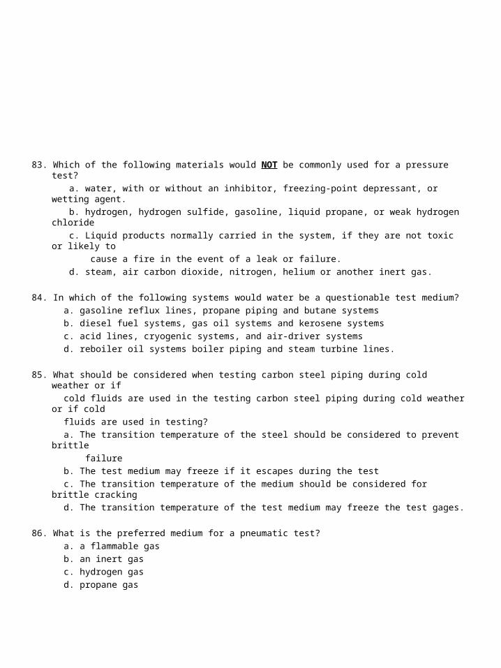
83. Which of the following materials would NOT be commonly used for a pressure test?
a. water, with or without an inhibitor, freezing-point depressant, or wetting agent.
b. hydrogen, hydrogen sulfide, gasoline, liquid propane, or weak hydrogen chloride
c. Liquid products normally carried in the system, if they are not toxic or likely to
cause a fire in the event of a leak or failure.
d. steam, air carbon dioxide, nitrogen, helium or another inert gas.
84. In which of the following systems would water be a questionable test medium?
a. gasoline reflux lines, propane piping and butane systems
b. diesel fuel systems, gas oil systems and kerosene systems
c. acid lines, cryogenic systems, and air-driver systems
d. reboiler oil systems boiler piping and steam turbine lines.
85. What should be considered when testing carbon steel piping during cold weather or if
cold fluids are used in the testing carbon steel piping during cold weather or if cold
fluids are used in testing?
a. The transition temperature of the steel should be considered to prevent brittle
failure
b. The test medium may freeze if it escapes during the test
c. The transition temperature of the medium should be considered for brittle cracking
d. The transition temperature of the test medium may freeze the test gages.
86. What is the preferred medium for a pneumatic test?
a. a flammable gas
b. an inert gas
c. hydrogen gas
d. propane gas

87. What type of piping usually has a pressure recorder attached in which a permanent
record of the test is made.
a. Boiler piping
b. underground piping
c. light hydrocarbon unit piping
d. operating unit piping
88. Which of the following piping should NOT be hammer tested?
a. pipe made from steel on a Fluid Catalytic Cracking Unit
b. steel pipe and lines off a crude tower on a crude still
c. cast iron and stress-relieved lines in caustic and corrosive service
d. ASTM A-106 Grade A pipe on a Catalytic Reforming Unit.
89. New construction piping should meet the requirements of as a minimum.
a. API 571
b. ASTM A-53
c. ASME B-31.3
d. ASME Std 607
90. When ASME B31.3 cannot be followed because of its new construction orientation,
which document should guide the Engineer/ Inspector?
a. API 574
b. API 575
c. ASME VIII
d. none of the above

91. A Piping Engineer must be: a. a degreed Mechanical Engineer b. acceptable to the owner/ user c. qualified as an API 570 Inspector d. a single entity (i.e., cannot be more than one person)
92. Which of the following is not a re-rating? a. a “scab” patch causing a decrease in design pressure b. a de-rating for corrosion c. a change in materials to a lower stress value d. an increase in the MAWP of the system.
93. A “piping system” does not include which of the following items? a. piping supports b. fittings c. bents d. valves
94. The boundary of a piping circuit should be sized : a. by the Inspector b. too provide for accurate record-keeping and field inspection c. to minimize TML’s d. to minimize the threat of CUI
95. When using statistical methods to assess corrosion in piping, it is very important to . a. properly select components to b. hydro test all piping c. ensure an adequate number of TML’s are placed. d. both a & c, above.

OPEN BOOK QUESTIONS
96. In the Barlow formula for determining pipe thickness, the term S stands for :
a. internal design gage pressure of the pipe in psi.
b. pressure design strength for internal pressure, in inches.
c. allowable unit stress at the design temperature, in psi
d. maximum strain at the average at the design operating temperature, in psi
97. At low pressures and temperatures, the thickness determined by the Barlow formula
may be so small that the pipe would have structural strength.
a. adequate
b. insufficient
c. ample
d. good
98. A seamless NPS 12, A-106 Grade A pipe operates at 300 degrees F and 941 psi.
The allowable stress is 16000 psi. Using the Barlow Equation, determine the
thickness required for the these conditions.
a. 0.375”
b. 0.750”
c. 0.353”
d. 0.706”
99. A seamless NPS 6, A-106 Grade A pipe operates at 300 degrees F and 941 psi. The
allowable stress is 16000 psi. The owner-user specified that the pipe must have 0.1”
allowed for corrosion allowance. Using the Barlow Equation, determine the thickness
required for these conditions.
a. 0.295”
b. 0.195”
c. 0.277’’
d. 0.352”
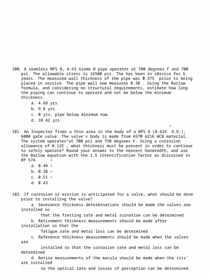
100. A seamless NPS 8, A-53 Grade B pipe operates at 700 degrees F and 700 psi. The allowable stress is 16500 psi. The has been in service for 6 years. The measured wall thickness of the pipe was 0.375” prior to being placed in service. The pipe wall now measures 0.30”. Using the Barlow formula, and considering no structural requirements, estimate how long the piping can continue to operate and not be below the minimum thickness.
a. 4.68 yrs
b. 9.8 yrs
c. 0 yrs, pipe below minimum now.
d. 10.42 yrs
101. An Inspector finds a thin area in the body of a NPS 8 (8.625” O.D.), 600# gate valve. The valve’s body is made from ASTM A216 WCB material. The system operates at 700 psi and 750 degrees F. Using a corrosion allowance of 0.125”, what thickness must be present in order to continue to safely operate? Round your answer to the nearest hundredth, and use the Barlow equation with the 1.5 intensification factor as discussed in RP 574.
a. 0.48”
b. 0.38”
c. 0.51”
d. 0.43”
102. If corrosion or erosion is anticipated for a valve, what should be done prior to installing the valve?
a. Severance thickness determinations should be made the valves are installed so
that the fretting rate and metal ruination can be determined
b. Retirement thickness measurements should be made after installation so that the
fatigue rate and metal loss can be determined
c. Reference thickness measurements should be made when the valves are
installed so that the corrosion rate and metal loss can be determined
d. Retina measurements of the macula should be made when the iris’ are installed
so the optical rate and losses of perception can be determined.
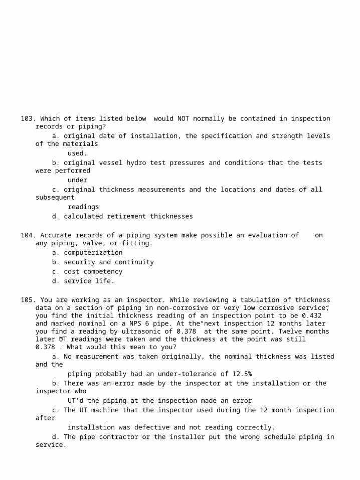
103. Which of items listed below would NOT normally be contained in inspection records or piping?
a. original date of installation, the specification and strength levels of the materials
used.
b. original vessel hydro test pressures and conditions that the tests were performed
under
c. original thickness measurements and the locations and dates of all subsequent
readings
d. calculated retirement thicknesses
104. Accurate records of a piping system make possible an evaluation of on any piping, valve, or fitting.
a. computerization
b. security and continuity
c. cost competency
d. service life.
105. You are working as an inspector. While reviewing a tabulation of thickness data on a section of piping in non-corrosive or very low corrosive service, you find the initial thickness reading of an inspection point to be 0.432” and marked nominal on a NPS 6 pipe. At the next inspection 12 months later you find a reading by ultrasonic of 0.378” at the same point. Twelve months later UT readings were taken and the thickness at the point was still 0.378”. What would this mean to you?
a. No measurement was taken originally, the nominal thickness was listed and the
piping probably had an under-tolerance of 12.5%
b. There was an error made by the inspector at the installation or the inspector who
UT’d the piping at the inspection made an error
c. The UT machine that the inspector used during the 12 month inspection after
installation was defective and not reading correctly.
d. The pipe contractor or the installer put the wrong schedule piping in service.
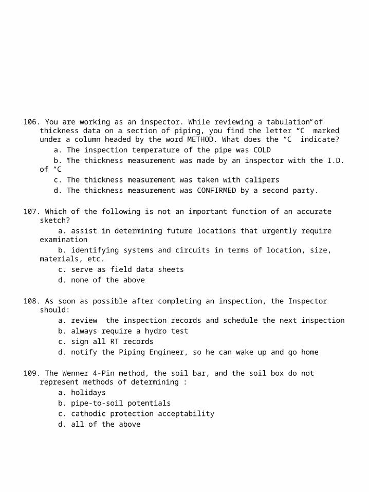
106. You are working as an inspector. While reviewing a tabulation of thickness data on a section of piping, you find the letter “C” marked under a column headed by the word METHOD. What does the “C” indicate?
a. The inspection temperature of the pipe was COLD
b. The thickness measurement was made by an inspector with the I.D. of “C”
c. The thickness measurement was taken with calipers
d. The thickness measurement was CONFIRMED by a second party.
107. Which of the following is not an important function of an accurate sketch?
a. assist in determining future locations that urgently require examination
b. identifying systems and circuits in terms of location, size, materials, etc.
c. serve as field data sheets
d. none of the above
108. As soon as possible after completing an inspection, the Inspector should:
a. review the inspection records and schedule the next inspection
b. always require a hydro test
c. sign all RT records
d. notify the Piping Engineer, so he can wake up and go home
109. The Wenner 4-Pin method, the soil bar, and the soil box do not represent methods of determining :
a. holidays
b. pipe-to-soil potentials
c. cathodic protection acceptability
d. all of the above

110. The total resistivity for a Wenner 4-Pin test that utilizes pins spaced 2 feet apart and
a “6” factor is :
a. 2298 ohm/cm
b. 3500 ohm/cm
c. 6000 ohm/cm
d. 8000 ohm/cm
111. Which of the following is not a consideration when using a soil bar?
a. using a standard
b. avoiding the addition of water
c. applying pressure on the soil bar after injection
d. none of the above
112. Which of the following is a consideration when using a soil box :
a. depth of Pins less than 4% of spacing
b. ensuring the soil has dried out before testing
c. avoiding contamination of the sample during handling storage
d. all of the above
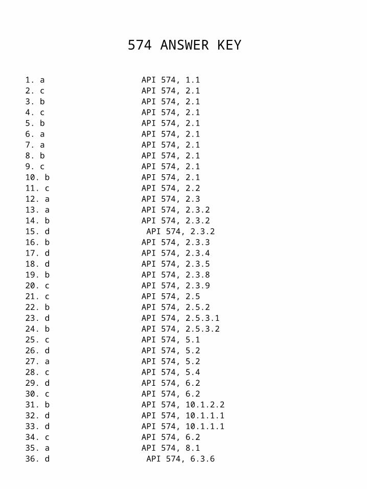
574 ANSWER KEY
1. a API 574, 1.12. c API 574, 2.13. b API 574, 2.14. c API 574, 2.15. b API 574, 2.16. a API 574, 2.17. a API 574, 2.18. b API 574, 2.19. c API 574, 2.110. b API 574, 2.111. c API 574, 2.212. a API 574, 2.313. a API 574, 2.3.214. b API 574, 2.3.215. d API 574, 2.3.216. b API 574, 2.3.317. d API 574, 2.3.418. d API 574, 2.3.519. b API 574, 2.3.820. c API 574, 2.3.921. c API 574, 2.522. b API 574, 2.5.223. d API 574, 2.5.3.124. b API 574, 2.5.3.225. c API 574, 5.126. d API 574, 5.227. a API 574, 5.228. c API 574, 5.429. d API 574, 6.230. c API 574, 6.231. b API 574, 10.1.2.232. d API 574, 10.1.1.133. d API 574, 10.1.1.134. c API 574, 6.235. a API 574, 8.136. d API 574, 6.3.6

37. c API 574, 6.3.738. a API 574, 6.3.139. d API 574, 6.3.540. b API 574, 6.3.741. c API 574, 6.3.142. c API 574, 10.1.1.143. b API 574, 10.1.1.144. b API 574, 10.1.1.145. a API 574, 10.1.1.246. b API 574, 10.1.1.347. c API 574, 10.1.1.348. c API 574, 10.1.1.349. c API 574, 10.1.1.350. b API 574, 10.1.1.351. b API 574, 10.1.1.452. c API 574, 10.1.1.553. d API 574, 10.1.1.154. d API 574, 10.2.1.155. b API 574, 10.1.2.156. c API 574, 10.1.2.157. d API 574, 10.1.2.258. c API 574, 10.1.1.759. a API 574, 10.3.1.460. d API 574, 12.561. c API 574, 10.2.1.162. b API 574, 10.2.1.263. d API 574, 10.2.1.264. b API 574, 10.2.1.365. c API 574, 10.2.1.466. c API 574, 10.2.1.467. b API 574, 10.2.1.468. d API 574, 10.2.1.469. d API 574, 10.2.1.470. b API 574, 10.2.1.5.171. b API 574, 10.2.1.5.272. b API 574, 10.2.1.5.273. a API 574, 10.2.1.5.374. a API 574, 10.2.1.5.375. C API 574, 10.2.1.5.476. b API 574, 10.2.1.6
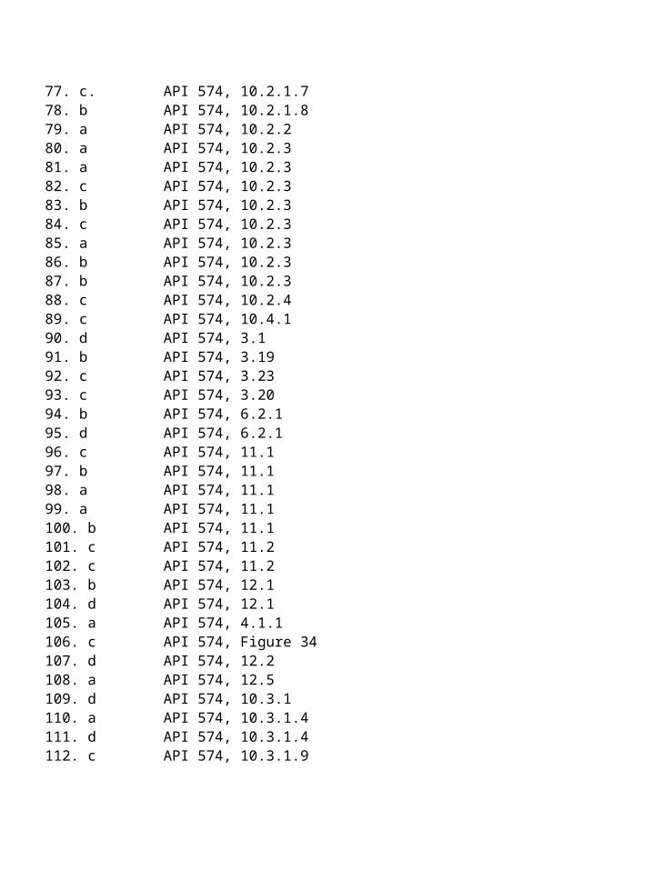
77. c. API 574, 10.2.1.778. b API 574, 10.2.1.879. a API 574, 10.2.280. a API 574, 10.2.381. a API 574, 10.2.382. c API 574, 10.2.383. b API 574, 10.2.384. c API 574, 10.2.385. a API 574, 10.2.386. b API 574, 10.2.387. b API 574, 10.2.388. c API 574, 10.2.489. c API 574, 10.4.190. d API 574, 3.191. b API 574, 3.1992. c API 574, 3.2393. c API 574, 3.2094. b API 574, 6.2.195. d API 574, 6.2.196. c API 574, 11.197. b API 574, 11.198. a API 574, 11.199. a API 574, 11.1100. b API 574, 11.1101. c API 574, 11.2102. c API 574, 11.2103. b API 574, 12.1104. d API 574, 12.1105. a API 574, 4.1.1106. c API 574, Figure 34107. d API 574, 12.2108. a API 574, 12.5109. d API 574, 10.3.1110. a API 574, 10.3.1.4111. d API 574, 10.3.1.4112. c API 574, 10.3.1.9
Related Documents