By Authority Of THE UNITED STATES OF AMERICA Legally Binding Document By the Authority Vested By Part 5 of the United States Code § 552(a) and Part 1 of the Code of Regulations § 51 the attached document has been duly INCORPORATED BY REFERENCE and shall be considered legally binding upon all citizens and residents of the United States of America. HEED THIS NOTICE : Criminal penalties may apply for noncompliance. Official Incorporator : THE EXECUTIVE DIRECTOR OFFICE OF THE FEDERAL REGISTER WASHINGTON, D.C. Document Name: CFR Section(s): Standards Body: e

Welcome message from author
This document is posted to help you gain knowledge. Please leave a comment to let me know what you think about it! Share it to your friends and learn new things together.
Transcript

By Authority OfTHE UNITED STATES OF AMERICA
Legally Binding Document
By the Authority Vested By Part 5 of the United States Code § 552(a) and Part 1 of the Code of Regulations § 51 the attached document has been duly INCORPORATED BY REFERENCE and shall be considered legally binding upon all citizens and residents of the United States of America. HEED THIS NOTICE: Criminal penalties may apply for noncompliance.
Official Incorporator:THE EXECUTIVE DIRECTOROFFICE OF THE FEDERAL REGISTERWASHINGTON, D.C.
Document Name:
CFR Section(s):
Standards Body:
e
carl
Typewritten Text
American Petroleum Institute
carl
Typewritten Text
30 CFR 250.803(b)(1)
carl
Typewritten Text
API 510: Pressure Vessel Inspection Code

Pressure Vessel Inspection Code: In-Service Inspection, Rating, Repair, and Alteration
Downstream Segment
API 510 NINTH EDITION, JUNE 2006
1) Reproduced By IHS
Wrth The Permission Of API
Under Royalty Agreement
®
SPECIAL NOTES
API publications necessarily address problems of a general nature. With respect to particular circumstances, local, state, and federal laws and regulations should be reviewed.
Neither API nor any of API's employees, subcontractors, consultants, committees, or other assignees make any warranty or representation, either express or implied, with respect to the accuracy, completeness, or usefulness of the information contained herein, or assume any liability or responsibility for any use, or the results of such use, of any information or process disclosed in this publication. Neither API nor any of API's employees, subcontractors, consultants, or other assignees represent that use ofthis publication would not infringe upon privately owned rights.
API publications may be used by anyone desiring to do so. Every effort has been made by the Institute to assure the accuracy and reliability of the data contained in them; however, the Institute makes no representation, warranty, or guarantee in connection with this publication and hereby expressly disclaims any liability or responsibility for loss or damage resulting from its use or for the violation of any authorities having jurisdiction with which this publication may conflict.
API publications are published to facilitate the broad availability of proven, sound engineering and operating practices. These publications are not intended to obviate the need for applying sound engineering judgment regarding when and where these publications should be utilized. The formulation and publication of API publications is not intended in any way to inhibit anyone from using any other practices.
Any manufacturer marking equipment or materials in conformance with the marking requirements of an API standard is solely responsible for complying with all the applicable requirements of that standard. API does not represent, warrant, or guarantee that such products do in fact conform to the applicable API standard.
All rights reserved. No part o/this work may be reproduced, stored in a retrieval system, or transmitted by any means, electronic, mechanical, photocopying, recording, or otherwise,
without prior written permission from the publisher. Contact the Publisher, API Publishing Services, I220 L Street, N W, Washington, D. C. 20005.
Copyright © 2006 American Petroleum Institute
FOREWORD
In December 1931, API and the American Society of Mechanical Engineers (ASME) created the Joint APIIASME Committee on Unfired Pressure Vessels. This committee was created to formulate and prepare for publication a code for safe practices in the design, construction, inspection, and repair of pressure vessels to be used in the petroleum industry. Entitled APIIASME Code for Unfired Pressure Vessels for Petroleum Liquids and Gases (commonly called the API/ASME Code for Unfired Pressure Vessels or API/ASME Code), the first edition of the code was approved for publication in 1934.
From its inception, the APIIASME Code contained Section I, which covered recommended practices for vessel inspection and repair and for establishing allowable working pressures for vessels in service. Section I recognized and afforded well-founded bases for handling various problems associated with the inspection and rating of vessels subject to corrosion. Although the provisions of Section I (like other parts of the API! ASME Code) were originally intended for pressure vessels installed in the plants of the petroleum industry, especially those vessels containing petroleum gases and liquids, these provisions were actually considered to be applicable to pressure vessels in most services. ASME's Boiler and Pressure Vessel Committee adopted substantially identical provisions and published them as a nonmandatory appendix in the 1950, 1952, 1956, and 1959 editions of Section VIII of the ASME Boiler and Pressure Vessel Code.
After the APII ASME Code was discontinued in 1956, a demand arose for the issuance of Section I as a separate publication, applicable not only to vessels built in accordance with any edition of the APIIASME Code but also to vessels built in accordance with any edition of Section VIII of the ASME Code. Such a publication appeared to be necessary to assure industry that the trend toward uniform maintenance and inspection practices afforded by Section] of the API! ASME Code would be preserved. API 510, first published in 1958, is intended to satisfY this need.
The procedures in Section] of the 1951 edition of the APIIASME Code, as amended by the March 16, 1954 addenda, have been updated and revised in API 510. Section I of the API! ASME Code contained references to certain design or construction provisions, so these references have been changed to refer to provisions in the AS ME Code. Since the release of the 1960 edition of the National Board Inspection Code, elements of the APlIASME Code have also been carried by the National Board Inspection Code.
It is the intent of API to keep this publication up to date. All pressure vessel owners and operators are invited to report their experiences in the inspection and repair of pressure vessels whenever such experiences may suggest a need for revising or expanding the practices set forth in API 510.
This edition of API 510 supersedes all previous editions of API 510. Each edition, revision, or addenda to this API standard may be used beginning with the date of issuance shown on the cover page for that edition, revision, or addenda. Each edition, revision, or addenda to this API standard becomes effective 6 months after the date of issuance for equipment that is rerated, reconstructed, relocated, repaired, modified (altered), inspected, and tested per this standard. During the 6-month time between the date of issuance of the edition, revision, or addenda and the effective date, the user shall specifY to which edition, revision, or addenda, and the equipment is to be rerated, reconstructed, relocated, repaired, modified (altered), inspected and tested.
Nothing contained in any API publication is to be construed as granting any right, by implication or otherwise, for the manufacture, sale, or use of any method, apparatus, or product covered by letters patent. Neither should anything contained in the publication be construed as insuring anyone against liability for infringement of letters patent.
iii

This document was produced under API standardization procedures that ensure appropriate notification and participation in the developmental process and is designated as an API standard. Questions concerning the interpretation of the content of this publication or comments and questions concerning the procedures under which this publication was developed should be directed in writing to the Director of Standards, American Petroleum Institute, 1220 L Street, N.W., Washington, D.C. 20005. Requests for permission to reproduce or translate all or any part of the material published herein should also be addressed to the director.
Generally, API standards are reviewed and revised, reaffirmed, or withdrawn at least every five years. A one-time extension of up to two years may be added to this review cycle. Status of the publication can be ascertained from the API Standards Department, telephone (202) 682-8000. A catalog of API publications and materials is published annually and updated quarterly by API, 1220 L Street, N.W., Washington, D.C. 20005.
Suggested revisions are invited and should be submitted to the Standards and Publications Department, API, 1220 L Street, NW, Washington, DC 20005, [email protected].
INSTRUCTIONS FOR SUBMITTING A PROPOSED REVISION TO THIS STANDARD UNDER CONTINUOUS MAINTENANCE
This standard is maintained under APT's continuous maintenance procedures. These procedures establish a documented program for regular publication of addenda or revisions, including timely and documented consensus action requests for revisions to any part of the standard. Proposed revisions shall be submitted to the Director, Standards Department, API, 1220 L Street, NW, Washington, D.C. 20005-4070, [email protected].

CONTENTS
Page
SCOPE .............................................................. 1-1 1.1 General Application ............................................... 1-1 I .2 Specific Applications .............................................. I-I 1.3 Recognized Technical Concepts ..................................... 1-2
2 REFERENCES ....................................................... 2-1
3 DEFINITIONS ........................................................ 3-1
4 OWNERIUSER INSPECTION ORGANIZATION .......................... 4-1 4.1 General. ....................................................... .4-1 4.2 Owner/user Organization Responsibilities ............................. 4-1
5 INSPECTION, EXAMINATION AND PRESSURE TESTING PRACTICES ..... 5-1 5.1 Inspection Plans .................................................. 5-1 5.2 Risk-based Inspection (Rbi) ........................................ 5-1 5.3 Preparation For Inspection .......................................... 5-2 5.4 Inspection For Types Of Damage Modes Of Deterioration And Failure ...... 5-3 5.5 General Types Oflnspection And Surveillance ......................... 5-4 5.6 Condition Monitoring Locations ..................................... 5-7 5.7 Condition Monitoring Methods ...................................... 5-7 5.8 Pressure Testing .................................................. 5-9 5.9 Material Verification And Traceability ............................... 5-10 5.10 Inspection Ofln-service Welds And Joints ........................... 5-11 5.11 Inspection Of Flanged Joints ...................................... 5-11
6 INTERV ALiFREQUENCY AND EXTENT OF INSPECTION . . . . . . . . . . . . . .. 6-1 6.1 General ......................................................... 6-1 6.2 Inspection During Installation And Service Changes ..................... 6-1 6.3 Risk-based Inspection ............................................. 6-1 6.4 External Inspection ............................................... 6-1 6.5 Internal And On-stream Inspection ................................... 6-2 6.6 Pressure-relieving Devices ......................................... 6-3
7 INSPECTION DATA EVALUATION, ANALYSIS, AND RECORDING ....... 7-1 7.1 Corrosion Rate Determination ....................................... 7-1 7.2 Remaining Life Calculations ........................................ 7-1 7.3 Maximum Allowable Working Pressure Determination .................. 7-2 7.4 Fitness For Service Analysis Of Corroded Regions ...................... 7-2 7.5 API RP 579 Fitness For Service Evaluations ........................... 7-3 7.6 Required Thickness Determination ................................... 7-4 7.7 Evaluation Of Existing Equipment With Minimal Documentation .......... 7-4 7.8 Reports And Records .............................................. 7-5
8 REPAIRS, ALTERATIONS, AND RERATING OF PRESSURE VESSELS .... 8-1 8.1 Repairs And Alterations ........................................... 8-1 8.2 Rerating ........................................................ 8-7
v

CONTENTS
Page
9 ALTERNATIVE RULES FOR EXPLORATION AND PRODUCTION PRESSURE VESSELS. . . . . . . . . . . . . . . . . . . . . . . . . . . . . . . . . . . . . . . . . . . . . . . . . . . . . . . . . .. 9-1 9.1 Scope And Specific Exemptions ..................................... 9-1 9.2 Definitions ...................................................... 9-1 9.3 Inspection Program ............................................... 9-1 9.4 Pressure Test. .................................................... 9-4 9.5 Safety Relief Devices .............................................. 9-4 9.6 Records ......................................................... 9-4
APPENDIX A ASME CODE EXEMPTIONS ................................ A-I APPENDIX B INSPECTOR CERTIFICATION .............................. B-1 APPENDIX C SAMPLE PRESSURE VESSEL INSPECTION RECORD .......... C-I APPENDIX D SAMPLE REPAIR, ALTERATION, OR RERATING OF
PRESSURE VESSEL FORM ................................. D-l APPENDIX E TECHNICAL INQUIRIES .................................... E-I
Tables 7-1 Values of Spherical Radius FactorK] ................................. 7-4 8-1 Welding Methods as Alternatives to Postweld Heat Treatment Qualification
Thickness for Test Plates and Repair Grooves. . . . . . . . . . . . . . . . . . . . . . . . . .. 8-7 Figures
8-1 Rerating Vessels Using the Latest Edition or Addendum of the ASME Code Allowable Stresses ................................................. 8-9


Pressure Vessel Inspection Code: In-Service Inspection, Rating, Repair, and Alteration
1 Scope 1.1 General Application
1.1.1 Coverage
This inspection code covers the in-service inspection, repair, alteration, and rerating activities for pressure vessels and the pressure-relieving devices protecting these vessels. This inspection code applies to all refining and chemical process vessels that have been placed in service unless specifically excluded per 1.2.2. This includes:
a. vessels constructed in accordance with an applicable construction code b. vessels constructed without a construction code (non-code)-A vessel not fabricated to a recognized construction code and meeting no known recognized standard c. vessels constructed and approved as jurisdictional special based upon jurisdiction acceptance of particular design, fabrication, inspection, testing, and installation d. non-standard vessels-A vessel fabricated to a recognized construction code but has lost it's nameplate or stamping.
The ASME Code and other construction codes are written for new construction; however, most of the technical requirements for design, welding, NDE, and materials can be applied to the inspection, rerating, repair, and alteration of in-service pressure vessels. If an item cannot follow the ASME Code because of its new construction orientation, requirements for design, material, fabrication, and inspection shall conform to API 510 rather than to the ASME Code. If in-service vessels are covered by requirements in the ASME Code and API 510 or if there is a conflict between the two codes, the requirements of API 510 shall take precedence. As an example of the intent of API 510, the phrase "applicable requirements of the ASME Code" has been used in API 510 instead of the phrase "in accordance with the ASME Code."
1.1.2 Intent
The application of this inspection code is restricted to owner/users that employ or have access to the following technically qualified individuals and organizations:
a. An authorized inspection agency; b. A repair organization; c. An engineer; d. An inspector; and, e. Examiners.
Inspectors are to be certified as stated in this inspection code (see Appendix B). Since other codes covering specific industries and general service applications already exist (e.g. NB-23), the refining and petrochemical industry has developed this inspection code to fulfill their own specific requirements for vessels and pressure-relieving devices that fit within the restrictions listed in the scope.
1.1.3 limitations
Adoption and use of this inspection code does not permit its use in conflict with any prevailing regulatory requirements. However, if the requirements of this code are more stringent than the requirements of the regulation, then the requirements of this code shall govern.
1.2 SpeCific Applications
1.2.1 Exploration and Production Vessels
All pressure vessels used for Exploration and Production (E&P) service [for example, drilling, producing, gathering, transporting, lease processing, and treating liquid petroleum, natural gas, and associated salt water (brine)] may be inspected under the alternative rules set forth in Section 9. Except for Section 6, all of the sections in this inspection code are applicable to pressure vessels in E&P service. The alternative rules in Section 9 are intended for services that may be regulated under safety, spill, emission, or transportation controls by the U.S. Coast Guard; the Office of Hazardous Materials Transportation of the U.S. Department of
1-1

1-2 API510
Transportation (DOT) and other units of DOT; the Minerals Management Service of the U.S. Department of the Interior; state and local oil and gas agencies; or any other regulatory commission.
1.2.2 Excluded and Optional Services
The following are excluded from the specific requirements of this inspection code:
a. Pressure vessels on movable structures covered by other jurisdictional regulations (see Appendix A (a)). b. All classes of containers listed for exemption in the scope of the applicable construction code (see Appendix A (b)). c. Pressure vessels that do not exceed the volumes and pressures listed in Appendix A (c).
1.3 Recognized Technical Concepts
This inspection code recognizes fitness-for-service concepts for evaluating in-service damage of pressure-containing components. API 579 provides detailed assessment procedures for specific types of damage that are referenced in this code.
This inspection code recognizes risk-based inspection (RBI) concepts for determining inspection intervals. API 580 provides guidelines for conducting a risk-based assessment.
SECTION 2-REFERENCES
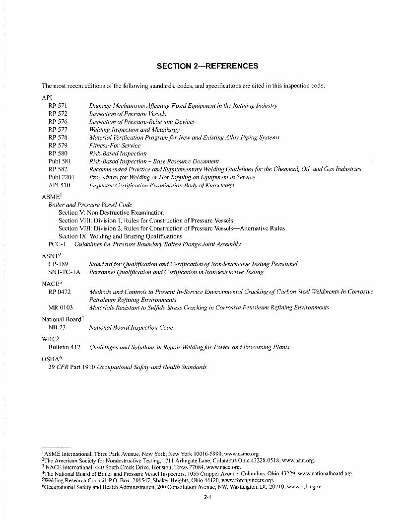
The most recent editions of the following standards, codes, and specifications are cited in this inspection code.
API RP 571 RP 572 RP 576 RP 577 RP 578 RP 579 RP 580 Pub I 581 RP 582 Pub I 2201 API510
ASMEI
Damage Mechanisms Affecting Fixed Equipment in the Refining Industry Inspection of Pressure Vessels Inspection of Pressure-Relieving Devices Welding Inspection and Metallurgy Material Verification Programjor New and Existing Alloy Piping Systems Fitness-For-Service Risk-Based Inspection Risk-Based Inspection - Base Resource Document Recommended Practice and Supplementary Welding Guidelinesfor the Chemical, Oil, and Gas Industries Procedures for Welding or Hot Tapping on Equipment in Service Inspector Certification Examination Body of Knowledge
Boiler and Pressure Vessel Code Section V: Non Destructive Examination Section VIII: Division I, Rules for Construction of Pressure Vessels Section VIII: Division 2, Rules for Construction of Pressure Vessels-Alternative Rules Section IX: Welding and Brazing Qualifications
PCC-I Guidelines for Pressure Boundary Bolted Flange Joint Assembly
ASNT2 CP-189 SNT-TC-IA
NACE3
Standardfor Qualification and Certification of Nondestructive Testing Personnel Personnel Qualification and Certification in Nondestructive Testing
RP 0472 Methods and Controls to Prevent In-Service Environmental Cracking of Carbon Steel Weldments In Corrosive Petroleum Rejining Environments
MR 0103 Materials Resistant to Sulfide Stress Cracking in Corrosive Petroleum Refining Environments
National Board4
NB-23 National Board Inspection Code
WRC5 Bulletin 412 Challenges and Solutions in Repair Weldingfor Power and Processing Plants
OSHA6 29 CFR Part 1910 Occupational Safety and Health Standards
1 ASME International, Three Park Avenue, New York, New York 10016-5990, www.asme.org 2The American Society for Nondestructive Testing, 1711 Arlingate Lane, Columbus Ohio 43228-0518, www.asnt.org. 3 NACE International, 440 South Creek Drive, Houston, Texas 77084, www.nace.org. 4The National Board of Boiler and Pressure Vessel Inspectors, 1055 Crupper Avenue, Columbus, Ohio 43229, www.nationalboard.org. 5Welding Research Council, P.O. Box 201547, Shaker Heights, Ohio 44120, www.forengineers.org. 60ccupational Safety and Health Administration, 200 Constitution Avenue, NW, Washington, DC 20210, www.osha.gov.
2-1


SECTION 3-DEFINITIONS
For the purposes ofthis code, the following definitions apply.
3.1 ACFM: Alternating current field measurement.
3.2 alteration: A physical change in any component that has design implications that affect the pressure-containing capability of a pressure vessel beyond the scope described in existing data reports. The following should not be considered alterations: any comparable or duplicate replacement, the addition of any reinforced nozzle less than or equal to the size of existing reinforced nozzles, and the addition of nozzles not requiring reinforcement.
3.3 applicable construction code: The code, code section, or other recognized and generally accepted engineering standard or practice to which the pressure vessel was built or which is deemed by the owner/user or the engineer to be most appropriate for the situation.
3.4 ASME code: refers to the ASME Boiler and Pressure Vessel Code including its addenda and code cases.
3.5 authorization: Approval/agreement to perform a specific activity (e.g. repair) prior to the activity being performed.
3.6 authorized inspection agency: Anyone of the following:
a. The inspection organization of the jurisdiction in which the pressure vessel is used. b. The inspection organization of an insurance company that is licensed or registered to write and does write pressure vessel insurance; c. The inspection organization of an owner or user of pressure vessels who maintains an inspection organization for his equipment only and not for vessels intended for sale or resale; or d. An independent organization or individual that is under contract to and under the direction of an owner/user and that is recognized or otherwise not prohibited by the jurisdiction in which the pressure vessel is used. The owner/user's inspection program shall provide the controls that are necessary when contract inspectors are used.
3.7 authorized pressure vessel inspector: An employee of an authorized inspection agency who is qualified and certified to perform inspections under this inspection code. A non-destructive (NDE) examiner is not required to be an authorized pressure vessel inspector. Whenever the term inspector is used in API 510, it refers to an authorized pressure vessel inspector.
3.8 class of vessels: Pressure vessels used in a common circumstance of service, pressure and risk.
3.9 condition monitoring locations (CMLs): Designated areas on pressure vessels where periodic examinations are conducted. Previously, they were normally referred to as "thickness monitoring locations (TMLs)".
3.10 construction code: The code or standard a vessel was originally built to, such as API! AS ME, API, or State Special! non-ASME.
3.11 controlled-deposition welding: Any welding technique used to obtain controlled grain refinement and tempering of the underlying heat affected zone (HAZ) in the base metal. Various controlled-deposition techniques, such as temper-bead (tempering of the layer below the current bead being deposited) and half-bead (requiring removal of one-half of the first layer), are included.
3.12 corrosion rate: The rate of metal loss due to the reaction(s) with its environment.
3.13 corrosion specialist: A person, acceptable to the owner/user, who has knowledge and experience in corrosion damage mechanisms, metallurgy, materials selection, and corrosion monitoring techniques.
3.14 corrosion under insulation (CUI): Refers to all forms of corrosion under insulation including stress corrosion cracking.
3.15 defect: An imperfection, whose type or size, exceeds the applicable acceptance criteria.
3.16 design temperature: The temperature used in the design of the pressure vessel per the applicable construction code.
3.17 documentation: Records containing descriptions of specific training, inspection, NDE, and pressure testing activities, or procedures for undertaking these activities.
3.18 ET: Eddy current examination technique.
3-1

3-2 API510
3.19 engineer: Pressure vessel engineer.
3.20 examiner: A person who assists the inspector by perfonning specific nondestructive examination (NDE) on pressure vessel components but does not evaluate the results of those examinations in accordance with API 510, unless specifically trained and authorized to do so by the owner/user.
3.21 external inspection: A visual inspection perfonned from the outside of a pressure vessel to find conditions that could impact the vessel's ability to maintain pressure integrity or conditions that compromise the integrity of the supporting structures, e.g. ladders, platfonns. This inspection may be done either while the vessel is operating or while the vessel is out-of-service.
3.22 fitness-for-service evaluation: A methodology whereby flaws and conditions contained within an equipment item are assessed in order to detennine the integrity of the equipment for continued service.
3.23 general corrosion: Corrosion that is distributed more or less unifonnly over the surface ofthe metal.
3.24 hold point: A point in the repair or alteration process beyond which work may not proceed until the required inspection or NDE has been perfonned and documented.
3.25 imperfections: Flaws or other discontinuities noted during inspection that mayor may not exceed the applicable acceptance criteria.
3.26 indications: A response or evidence resulting from the application of a nondestructive examination.
3.27 industry-qualified UT shear wave examiner: A person who possesses an ultrasonic shear wave qualification from API (e.g. API-QUTE) or an equivalent qualification approved by the owner/user.
3.28 in-service: Designates a pressure vessel that has been placed in operation as opposed to new construction prior to being placed in service or retired vessels. A pressure vessel not in operation due to an outage is still considered an in-service pressure vessel.
3.29 in-service inspection: All inspection activities associated with a pressure vessel once it has been placed in service.
3.30 inspection: The external, internal, or on-stream evaluation (or any combination of the three) of a pressure vessel's condition.
3.31 inspection code: Shortened title for API 510.
3.32 inspection plan: A strategy defining how and when a pressure vessel or pressure-relieving device will be inspected, repaired, and/or maintained.
3.33 inspector: A shortened title for an authorized pressure vessel inspector.
3.34 internal inspection: An inspection perfonned from the inside of a pressure vessel using visual and lor NDE techniques.
3.35 jurisdiction: A legally constituted government administration that may adopt rules relating to pressure vessels.
3.36 localized corrosion: Corrosion that is confined to a limited area of the metal surface.
3.37 maximum allowable working pressure (MAWP): The maximum gauge pressure pennitted at the top of a pressure vessel in its operating position for a designated temperature. This pressure is based on calculations using the minimum (or average pitted) thickness for all critical vessel elements, (exclusive of thickness designated for corrosion) and adjusted for applicable static head pressure and non-pressure loads, e.g. wind, earthquake, etc.
3.38 minimum design metal temperature (MDMT): The lowest temperature at which a significant load can be applied to a pressure vessel as defined in the applicable construction code (e.g. ASME Code, Section VIII: Division I, Paragraph UG-20(b)).
3.39 MT: Magnetic particle examination technique.
3.40 NDE: Nondestructive examination.
3.41 non-pressure boundary: The portion of the vessel that does not contain the process pressure, e.g. trays, baffles, nonstiffening insulation support rings, etc.
3.42 on-stream: A condition where a pressure vessel has not been prepared for an internal inspection.
PRESSURE VESSEL INSPECTION CODE: IN-SERVICE INSPECTION, RATING, REPAIR, AND ALTERATION 3-3
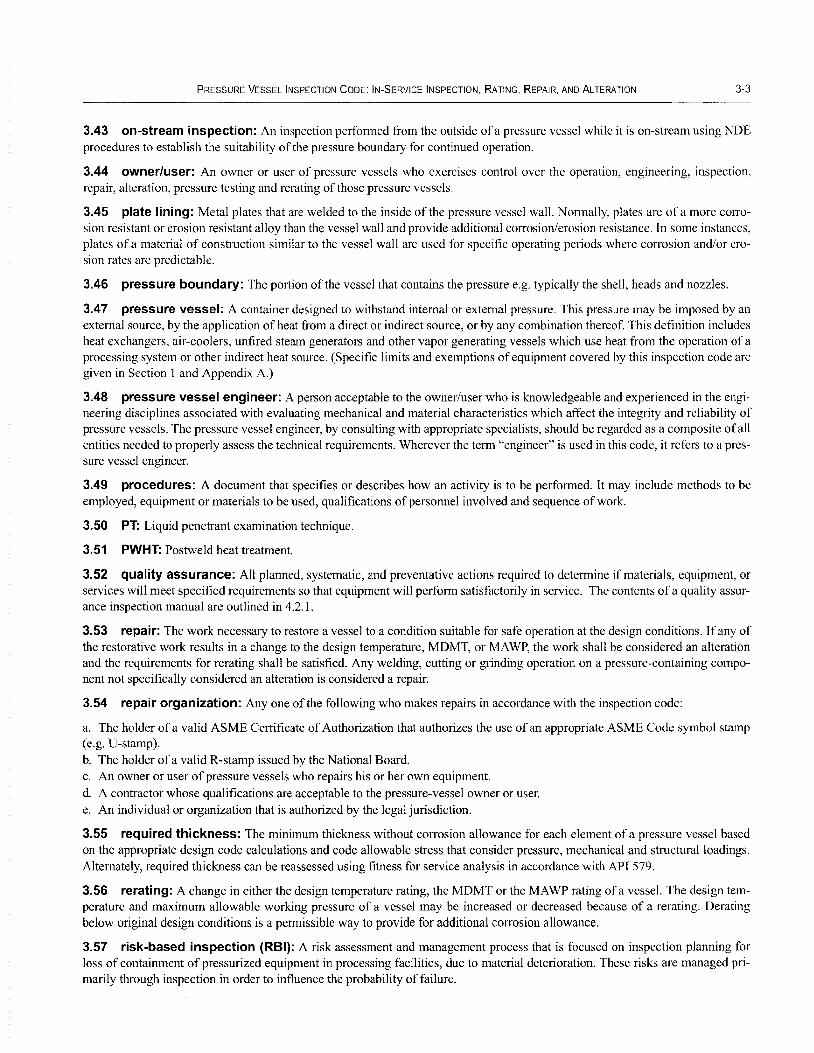
3.43 on-stream inspection: An inspection performed from the outside ofa pressure vessel while it is on-stream using NDE procedures to establish the suitability of the pressure boundary for continued operation.
3.44 owner/user: An owner or user of pressure vessels who exercises control over the operation, engineering, inspection, repair, alteration, pressure testing and rerating of those pressure vessels.
3.45 plate lining: Metal plates that are welded to the inside of the pressure vessel wall. Normally, plates are of a more COITOsion resistant or erosion resistant alloy than the vessel wall and provide additional cOITosionlerosion resistance. In some instances, plates of a material of construction similar to the vessel wall are used for specific operating periods where corrosion and/or erosion rates are predictable.
3.46 pressure boundary: The portion of the vessel that contains the pressure e.g. typically the shell, heads and nozzles.
3.47 pressure vessel: A container designed to withstand internal or external pressure. This pressure may be imposed by an external source, by the application of heat from a direct or indirect source, or by any combination thereof. This definition includes heat exchangers, air-coolers, unfired steam generators and other vapor generating vessels which use heat from the operation of a processing system or other indirect heat source. (Specific limits and exemptions of equipment covered by this inspection code are given in Section 1 and Appendix A.)
3.48 pressure vessel engineer: A person acceptable to the owner/user who is knowledgeable and experienced in the engineering disciplines associated with evaluating mechanical and material characteristics which affect the integrity and reliability of pressure vessels. The pressure vessel engineer, by consulting with appropriate specialists, should be regarded as a composite of all entities needed to properly assess the technical requirements. Wherever the term "engineer" is used in this code, it refers to a pressure vessel engineer.
3.49 procedures: A document that specifies or describes how an activity is to be performed. It may include methods to be employed, equipment or materials to be used, qualifications of personnel involved and sequence of work.
3.50 PT: Liquid penetrant examination technique.
3.51 PWHT: Postweld heat treatment.
3.52 quality assurance: All planned, systematic, and preventative actions required to determine if materials, equipment, or services will meet specified requirements so that equipment will perform satisfactorily in service. The contents of a quality assurance inspection manual are outlined in 4.2.1.
3.53 repair: The work necessary to restore a vessel to a condition suitable for safe operation at the design conditions. If any of the restorative work results in a change to the design temperature, MDMT, or MA WP, the work shall be considered an alteration and the requirements for rerating shall be satisfied. Any welding, cutting or grinding operation on a pressure-containing component not specifically considered an alteration is considered a repair.
3.54 repair organization: Anyone of the following who makes repairs in accordance with the inspection code:
a. The holder of a valid ASME Certificate of Authorization that authorizes the use of an appropriate ASME Code symbol stamp (e.g. U-stamp). b. The holder of a valid R-stamp issued by the National Board. c. An owner or user of pressure vessels who repairs his or her own equipment. d. A contractor whose qualifications are acceptable to the pressure-vessel owner or user. e. An individual or organization that is authorized by the legal jurisdiction.
3.55 required thickness: The minimum thickness without cOITosion allowance for each element of a pressure vessel based on the appropriate design code calculations and code allowable stress that consider pressure, mechanical and structural loadings. Alternately, required thickness can be reassessed using fitness for service analysis in accordance with API 579.
3.56 rerating: A change in either the design temperature rating, the MDMT or the MA WP rating of a vessel. The design temperature and maximum allowable working pressure of a vessel may be increased or decreased because of a rerating. Derating below original design conditions is a permissible way to provide for additional cOITosion allowance.
3.57 risk-based inspection (RBI): A risk assessment and management process that is focused on inspection planning for loss of containment of pressurized equipment in processing facilities, due to material deterioration. These risks are managed primarily through inspection in order to influence the probability of failure.
3-4 API510
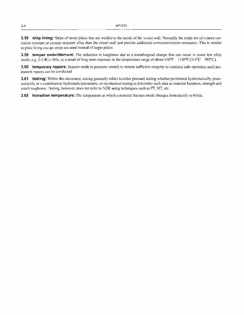
3.58 strip lining: Strips of metal plates that are welded to the inside of the vessel wall. Normally the strips are ofa more corrosion resistant or erosion resistant alloy than the vessel wall and provide additional corrosion/erosion resistance. This is similar to plate lining except strips are used instead of larger plates.
3.59 temper embrittlement: The reduction in toughness due to a metallurgical change that can occur in some low alloy steels, e.g. 2- I /4Cr-l Mo, as a result of long term exposure in the temperature range of about 650°F - 11 OO°F (345°C - 595°C).
3.60 temporary repairs: Repairs made to pressure vessels to restore sufficient integrity to continue safe operation until permanent repairs can be conducted
3.61 testing: Within this document, testing generally refers to either pressure testing whether performed hydrostatically, pneumatically or a combination hydrostatic/pneumatic, or mechanical testing to determine such data as material hardness, strength and notch toughness. Testing, however, does not refer to NDE using techniques such as PT, MT, etc.
3.62 transition temperature: The temperature at which a material fracture mode changes from ductile to brittle.
SECTION 4-0WNERIUSER INSPECTION ORGANIZATION
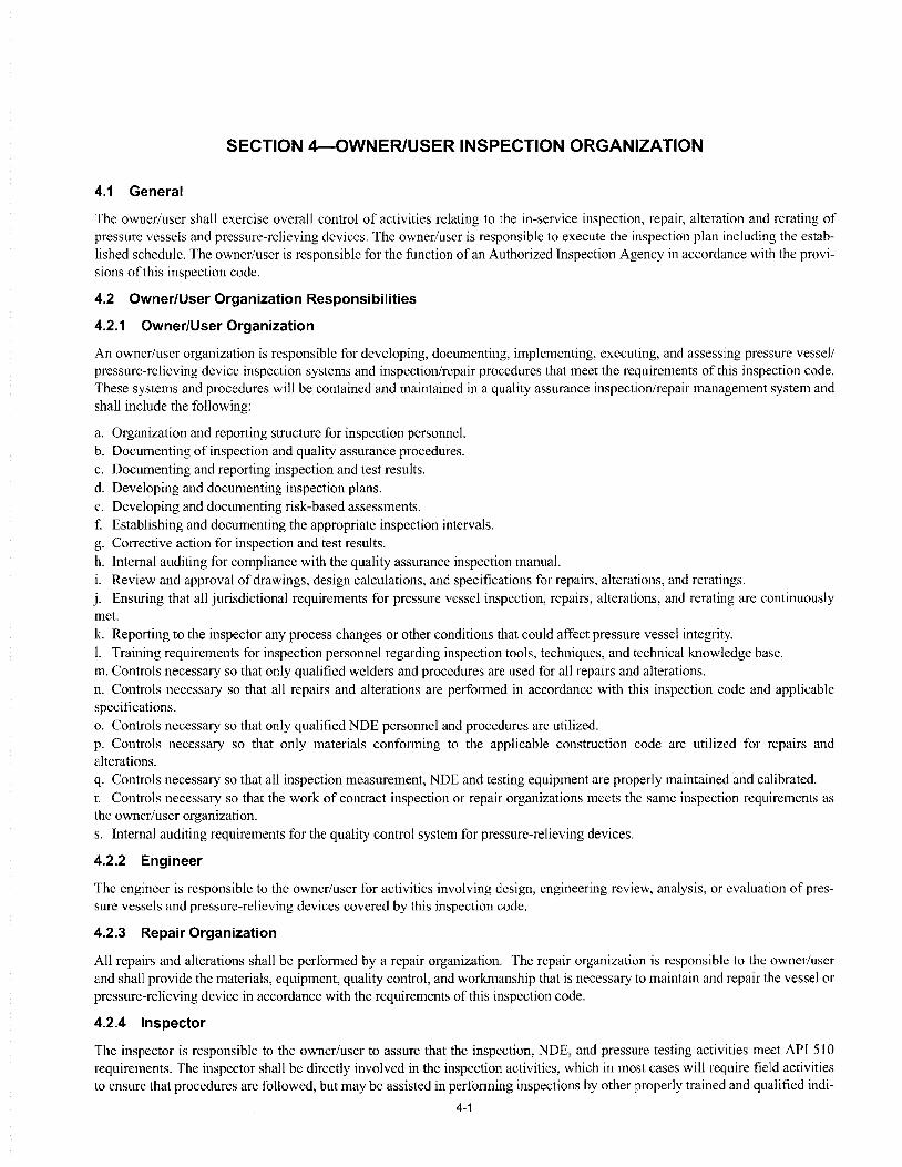
4.1 General
The owner/user shall exercise overall control of activities relating to the in-service inspection, repair, alteration and rerating of pressure vessels and pressure-relieving devices. The owner/user is responsible to execute the inspection plan including the established schedule. The owner/user is responsible for the function of an Authorized Inspection Agency in accordance with the provisions of this inspection code.
4.2 Owner/User Organization Responsibilities
4.2.1 Owner/User Organization
An owner/user organization is responsible for developing, documenting, implementing, executing, and assessing pressure vessell pressure-relieving device inspection systems and inspection/repair procedures that meet the requirements of this inspection code. These systems and procedures will be contained and maintained in a quality assurance inspection/repair management system and shall include the following:
a. Organization and reporting structure for inspection personnel. b. Documenting of inspection and quality assurance procedures. c. Documenting and reporting inspection and test results. d. Developing and documenting inspection plans. e. Developing and documenting risk-based assessments. f. Establishing and documenting the appropriate inspection intervals. g. Corrective action for inspection and test results. h. Internal auditing for compliance with the quality assurance inspection manual. i. Review and approval of drawings, design calculations, and specifications for repairs, alterations, and reratings. j. Ensuring that all jurisdictional requirements for pressure vessel inspection, repairs, alterations, and rerating are continuously met. k. Reporting to the inspector any process changes or other conditions that could affect pressure vessel integrity. 1. Training requirements for inspection personnel regarding inspection tools, techniques, and technical knowledge base. m. Controls necessary so that only qualified welders and procedures are used for all repairs and alterations. n. Controls necessary so that all repairs and alterations are performed in accordance with this inspection code and applicable specifications. o. Controls necessary so that only qualified NDE personnel and procedures are utilized. p. Controls necessary so that only materials conforming to the applicable construction code are utilized for repairs and alterations. q. Controls necessary so that all inspection measurement, NDE and testing equipment are properly maintained and calibrated. r. Controls necessary so that the work of contract inspection or repair organizations meets the same inspection requirements as the owner/user organization. s. Internal auditing requirements for the quality control system for pressure-relieving devices.
4.2.2 Engineer
The engineer is responsible to the owner/user for activities involving design, engineering review, analysis, or evaluation of prcssure vessels and pressure-relieving devices covered by this inspection code.
4.2.3 Repair Organization
All repairs and alterations shall be performed by a repair organization. The repair organization is responsible to the owner/user and shall provide the materials, equipment, quality control, and workmanship that is necessary to maintain and repair the vesscJ or pressure-relieving device in accordance with the requirements of this inspection code.
4.2.4 Inspector
The inspector is responsible to the owner/user to assure that the inspection, NDE, and pressure testing activities meet API 510 requirements. The inspector shall be directly involved in the inspection activities, which in most cases will require field activities to ensure that procedures are followed, but may be assisted in performing inspections by other properly trained and qualified indi-
4-1

4-2 API 510
viduals, who are not inspectors e.g. examiners and operating personnel. However, all NDE results must be evaluated and accepted by the inspector.
Inspectors shall be certified in accordance with the provisions of Appendix B.
4.2.5 Examiners
4.2.5.1 The examiner shall perform the NDE in accordance with job requirements.
4.2.5.2 The examiner does not need API 510 inspector certification and does not need to be an employee of the owner/user. The examiner does need to be trained and competent in the NDE procedures being used and may be required by the owner/user to prove competency by holding certifications in those procedures. Examples of certifications that may be required include ASNT SNT-TC-IA, CP-189, and AWS Welding Inspector Certification.
4.2.5.3 The inspector's employer shall maintain certification records of the examiners employed, including dates and results of personnel qualifications. These records shall be available to the inspector.
4.2.6 Other Personnel
Operating, maintenance, or other personnel who have special knowledge related to particular pressure vessels shall be responsible for promptly making the inspector or engineer aware of any unusual conditions that may develop.

SECTION 5-INSPECTION, EXAMINATION AND PRESSURE TESTING PRACTICES
5.1 Inspection Plans
An inspection plan shall be established for all pressure vessels and pressure-relieving devices within the scope of this code.
5.1.1 Development of an Inspection Plan
5.1.1.1 The inspection plan should be developed by the inspector or engineer. A corrosion specialist shall be consulted when needed to clarifY potential damage mechanisms and specific locations where they may occur. A corrosion specialist shall be consulted when developing the inspection plan for vessels that operate at elevated temperatures (above 750 0 P (400°C)).
5.1.1.2 The inspection plan is developed from the analysis of several sources of data. Equipment shall be evaluated based on present or possible types of damage mechanisms. The methods and the extent ofNDE shall be evaluated to assure they can adequately identifY the damage mechanism and the severity of damage. Examinations must be scheduled at intervals that consider the:
a. Type of damage; b. Rate of damage progression; c. Tolerance of the equipment to the type of damage; d. Probability of the NDE method to identifY the damage; and e. Maximum intervals as defined in codes and standards.
5.1.1.3 The inspection plan should be developed using the most appropriate sources of information including those listed in Section 2 of this inspection code. Inspection plans shall be reviewed and amended as needed when variables that may impact damage mechanisms and/or deterioration rates are identified.
5.1.2 Minimum Contents of an Inspection Plan
The inspection plan shall contain the inspection tasks and schedule required to monitor damage mechanisms and assure the mechanical integrity of the equipment (pressure vessel or pressure-relieving device). The plan should:
a. Define the type(s) of inspection needed, e.g. internal, external; b. IdentifY the next inspection date for each inspection type; c. Describe the inspection and NDE techniques; d. Describe the extent and locations of inspection and NDE; e. Describe the surface cleaning requirements needed for inspection and examinations; f. Describe the requirements of any needed pressure test, e.g. type oftest, test pressure, and duration; and g. Describe any required repairs.
Generic inspection plans based on industry standards and practices may be used. The inspection plan mayor may not exist in a single document however the contents ofthe plan should be readily accessible from inspection data systems.
5.1.3 Additional Contents of an Inspection Plan
Inspection plans may also contain other details to assist in understanding the rationale for the plan and in executing the plan. Some of these details may include:
a. Describing the types of damage anticipated or experienced in the equipment; b. Defining the location of the damage; and c. Defining any special access requirements.
5.2 Risk-based Inspection (RBI)
RBI can be used to determine inspection intervals and the type and extent of future inspection/examinations. A RBI assessment determines risk by combining the probability and the consequence of equipment failure.
When an owner/user chooses to conduct a RBI assessment, it must include a systematic evaluation of both the probability of failure and the consequence of failure in accordance with API 580. API 581 details an RBI methodology that has all of the key elements defined in API 580, section 1.1.l.
5-1

5-2 API 510
Identifying and evaluating potential damage mechanisms, current equipment condition and the effectiveness of the past inspections are important steps in assessing the probability of a pressure vessel failure. IdentifYing and evaluating the process fluid(s), potential injuries, environmental damage, equipment damage, and equipment downtime are important steps in assessing the consequence of a pressure vessel failure.
5.2.1 Probability Assessment
The probability assessment should be in accordance with API 580, Section 9, and must be based on all forms of damage that could reasonably be expected to affect a vessel in any particular service. Examples ofthose damage mechanisms include: internal or external metal loss from localized or general corrosion, all forms of cracking, and any other forms of metallurgical, corrosion, or mechanical damage, (e.g. fatigue, embrittlement, creep, etc.) Additionally, the effectiveness of the inspection practices, tools, and techniques used for finding the potential damage mechanisms must be evaluated.
Other factors that should be considered in a probability assessment include:
a. Appropriateness of the materials of construction.
b. Vessel design conditions, relative to operating conditions.
c. Appropriateness of the design codes and standards utilized.
d. Effectiveness of corrosion monitoring programs.
e. The quality of maintenance and inspection quality assurance/quality control programs.
Equipment failure data will also be important information for this assessment.
5.2.2 Consequence Assessment
The consequence of a release is dependent on type and amount of process fluid contained in the equipment. The consequence assessment should be in accordance with API 580, Section 10 and must consider the potential incidents that may occur as a result of fluid release, the size of a potential release, and the type of a potential release, (includes explosion, fire, or toxic exposure.) The assessment should also determine the potential incidents that may occur as a result of fluid release, which may include: health effects, environmental damage, equipment damage, and equipment downtime.
5.2.3 Documentation
It is essential that all RBI assessments be thoroughly documented in accordance with API 580, Section 16, clearly defining all the factors contributing to both the probability and consequence of a failure of the vessel.
After an RBI assessment is conducted, the results can be used to establish the vessel inspection plan and better define the following:
a. The most appropriate inspection and NDE methods, tools, and techniques;
b. The extent ofNDE (e.g. percentage of vessel to examine);
c. The interval for internal, external, and on-stream inspections;
d. The need for pressure testing after damage has occurred or after repairs/alterations have been completed; and
e. The prevention and mitigation steps to reduce the probability and consequence of a vessel failure. (e.g. repairs, process changes, inhibitors, etc.)
5.2.4 Frequency of RBI Assessments
When RBI assessments are used to set vessel inspection intervals, the assessment shall be updated after each vessel inspection as defined in API 580, Section 14. The RBI assessment shall also be updated each time process or hardware changes are made that could significantly affect damage rates or damage mechanisms.
5.3 Preparation for Inspection
Safety precautions are important in pressure vessel inspection and maintenance activities because some process fluids are harmful to human health. Also, pressure vessels are enclosed spaces, and internal activities involve exposure to all of the hazards of confined space entry. Regulations (e.g. those administered by Occupational Safety and Health Administration-OSHA) govern many aspects of vessel entry and must be followed. In addition, the owner/user's safety procedures must be reviewed and followed.
PRESSURE VESSEL INSPECTION CODE: IN-SERVICE INSPECTION, RATING, REPAIR, AND ALTERATION 5-3
5.3.1 Equipment
All tools, equipment, and personal protective equipment used during vessel work (inspection, NDE, pressure testing, repairs, and alterations) should be checked prior to use. Nondestructive examination equipment and the repair organization's equipment is subject to the owner/user's safety requirements for electrical equipment. Other equipment that might be needed for the vessel work, such as planking, scaffolding, and portable ladders, should be checked before being used. Personal protective equipment shall be worn when required either by regulations, the owner/user, or the repair organization.
5.3.2 Communication
Before starting any vessel inspection and maintenance activities (NDE, pressure testing, repair, or alteration) personnel should obtain permission to work in the vicinity from operating personnel responsible for the pressure vessel. When individuals are inside a vessel, all persons working around the vessel should be informed that people are working inside the vessel. Individuals working inside the vessel should be informed when any work is going to be done on the vessel's exterior.
5.3.3 Vessel Entry
Prior to entering a vessel, the vessel shall be isolated from all sources of liquids, gases, vapors, radiation, and electricity. The vessel should be drained, purged, cleaned, ventilated, and gas tested before it is entered. Procedures to ensure continuous safe ventilation and precautions to ensure safe egress/emergency evacuation of personnel from the vessel should be clear. Documentation of these precautions is required prior to any vessel entry. Before entering a vessel, individuals must obtain permission from the responsible operating personnel. Where required, personnel protective equipment shall be worn that will protect the eyes, lungs, and other parts of the body from specific hazards that may exist in the vessel.
5.3.4 Records Review
Before performing any of the required API 510 inspections, inspectors shall familiarize themselves with prior history of the vessels for which they are responsible. In particular, they should review the vessel's prior inspection results, prior repairs, current inspection plan, andlor other similar service inspections. A general overview of the types of damage and failure modes experienced by pressure equipment is provided in API 571 and API 579, Appendix G.
5.4 Inspection for Types of Damage Modes of Deterioration and Failure
5.4.1 Pressure vessels are susceptible to various types of damage by several mechanisms. Typical damage types and mechanisms are as follows.
a. General and local metal loss: 1. Sulfidation; 2. Oxidation; 3. Microbiologically induced corrosion; 4. Naphthenic acid corrosion; 5. Erosion/erosion-corrosion; 6. Galvanic.
b. Surface connected cracking: 1. Fatigue; 2. Caustic stress corrosion cracking; 3. Sulfide stress corrosion cracking.
c. Subsurface cracking: Hydrogen induced cracking.
d. Microfissuring/microvoid formation: I. High temperature hydrogen attack; 2. Creep.
e. Metallurgical changes: I. Graphitization; 2. Temper embrittlement.
f. Blistering: Hydrogen blistering.
5-4
g. Dimensional changes:
I. Creep and stress rupture;
2. Thermal.
h. Material Properties Changes:
Brittle fracturc.
API510
5.4.2 The presence or potential of damage in a vessel is dependent upon its material of construction, design, construction, and operating conditions. The inspector should be familiar with these conditions and with the causes and characteristics of potential defects and damage mechanisms.
5.4.3 Detailed information concerning common damage mechanisms (critical factors, appearance, and typical inspection and monitoring techniques) is found in API 571. Additional recommended inspection practices are described in API 572.
5.5 General Types of Inspection and Surveillance
5.5.1 General
Different types of inspections and examinations are appropriate depending on the circumstances and the pressure vessel. These include the following:
a. Internal inspection. b. On-stream inspection.
c. External inspection.
d. Thickness inspection.
e. Corrosion under insulation (CUI) inspection.
Inspections should be conducted in accordance with the inspection plan. Refer to Section 6 for the interval/frequency and extent of inspection.
Imperfections identified during inspections and examinations should be characterized, sized, and evaluated per Section 7.
5.5.2 Internal Inspection
5.5.2.1 General
The internal inspection shall be performed by an inspector in accordance with the inspection plan. An internal inspection is conducted inside the vessel and shall provide a thorough check of internal pressure boundary surfaces for damage. A primary goal of the internal inspection is to find damage that cannot be found by regular monitoring of external CMLs. Specific NDE techniques, e.g. WFMT, ACFM, ET, PT, etc., may be required by the owner/user to find damage specific to the vessel or service conditions.
API 572, provides more information on pressure vessel inspection and should be used when performing this inspection.
For equipment not designed for entrance by personnel, inspection ports shall be opened for examination of surfaces. Remote visual inspection techniques may aid the check of these equipment internal surfaces.
5.5.2.2 Vessel Internals
When vessels are equipped with removable internals, internals may need to be removed, to the extent necessary, to allow inspection of pressure boundary surfaces. The internals need not be removed completely as long as reasonable assurance exists that damage in regions rendered inaccessible by the internals is not occurring to an extent beyond that found in more accessible parts of the vessel.
Inspectors may inspect the non-pressure internals, if requested by other operations personnel, and report current condition to the appropriate operation personnel.
5.5.2.3 DepOSits and Linings
The inspector, in consultation with the corrosion specialist, should determine when it is necessary to remove deposits or linings to perform adequate inspections.

PRESSURE VESSEL INSPECTION CODE: IN-SERVICE INSPECTION, RATING, REPAIR, AND ALTERATION 5-5
Whenever operating deposits, such as coke, are normally permitted to remain on a vessel surface, it is important to determine whether these deposits adequately protect the vessel or do not cause deterioration of the surface. Spot examinations at selected areas, with the deposit thoroughly removed, may be required to determine the vessel surface condition.
Internal linings (e.g. refractory, strip linings, plate linings, coatings) should be thoroughly examined. If internal linings are in good condition and there is no reason to suspect that damage is occurring behind them, it is not necessary to remove linings during the internal inspection. If the lining appears damaged, bulged or cracked, it may be advisable to remove small portions of the linings to investigate the condition of the lining and the vessel surface beneath. External NDE techniques may bc advisable to explore for damage beneath linings.
5.5.3 On-stream Inspection
5.5.3.1 The on-stream inspection may be required by the inspection plan. All on-stream inspections should be conducted by either an inspector or examiner. All on-stream inspection work performed by an examiner shall be authorized and approved by the inspector. When on-stream inspections of the pressure boundary are specified, they shall be designed to detect the damage mechanisms identified in the inspection plan.
5.5.3.2 The inspection may include several NDE techniques to check for various types of damage. Techniques used in onstream inspections are chosen for their ability to identify particular internal damage mechanisms from the exterior and their capabilities to perform at the on-stream conditions of the pressure vessel (e.g. metal temperatures). The external thickness inspection described in 5.5.4 may be a part of an on-stream inspection.
5.5.3.3 On-stream inspection may be acceptable in lieu of internal inspection for vessels under the specific circumstances defined in 6.5.2. In situations where on-stream inspection is acceptable, such inspection may be conducted either while the vessel is depressurized or pressured.
5.5.4 External Inspection
5.5.4.1 General
5.5.4.1.1 External inspections are normally performed by an inspector; however, other qualified personnel may conduct the external inspection when acceptable to the inspector. In such cases, the persons performing the external inspection in accordance with API 510 shall be qualified with appropriate training.
5.5.4.1.2 External inspections are performed to check the condition of the outside surface of the vessel, insulation systems, painting and coating systems, supports, associated structure; and to check for leakage, hot spots, vibration, the allowance for expansion and the general alignment of the vessel on its supports. During the external inspection, particular attention should be given to welds used to attach components (e.g. reinforcement plates, and clips) for cracking or other defects.
Any signs of leakage should be investigated so that the sources can be established. Normally, weep holes in reinforcing plates should remain open to provide visual evidence ofleakage as well as to prevent pressure build-up behind the reinforcing plate.
5.5.4.1.3 Vessels shall be examined for visual indications of bulging, out-of-roundness, sagging, and distortion. If any distortion of a vessel is suspected or observed, the overall dimensions of the vessel shall be checked to determine the extent of the distortion.
API 572 provides more information on pressure vessel inspection and should be used when performing this inspection.
Any personnel who observe vessel deterioration should report the condition to the inspector.
5.5.4.2 Buried Vessels
Buried vessels shall be inspected to determine their external surface condition. The inspection interval shall be based on corrosion rate information obtained from one or more ofthe following methods:
a. During maintenance activity on connecting piping of similar material;
b. From the interval examination of similarly buried corrosion test coupons of like material;
c. From representative portions of the actual vessel; or
d. From a vessel in similar circumstances.

5-6 API510
5.5.5 Thickness Inspection
5.5.5.1 Thickness measurements are taken to verity the thickness of vessel components. This data is used to determine the corrosion rates and remaining life of the vessel. Thickness measurements shall be obtained by the inspector or examiner.
5.5.5.2 Although thickness measurements are not required to be obtained while the pressure vessel is on-stream, on-stream thickness monitoring is a good tool for monitoring corrosion and assessing potential damage due to process or operational changes.
5.5.5.3 The inspector should consult with a corrosion specialist when the short term corrosion rate changes significantly from the previous identified rate to determine the cause. Appropriate responses to accelerated corrosion rates may include, additional thickness readings, UT scans in suspect areas, corrosion/process monitoring, and revisions to the vessel's inspection plan.
5.5.5.4 The owner/user is responsible to assure that all individuals taking thickness readings are trained and qualified in accordance with the applicable procedure used during the examination.
5.5.6 CUI Inspection
5.5.6.1 Susceptible Temperature Range
Inspection for CUI shall be considered for externally-insulated vessels and those that are in intermittent service or operate between:
a. 10°F (-12°C) and 3S0°F (l7S°C) for carbon and low alloy steels
b. 140°F (60°C) and 400°F (20S°C) for austenitic stainless steels.
5.5.6.2 Susceptible Locations
With carbon and low alloy steels, CUI usually causes localized corrosion. With austenitic stainless steel materials, CUI usually is in the form of stress corrosion cracking. When developing the inspection plan for CUI inspection, the inspector should consider areas that are most susceptible to CUI. On vessels, these areas include:
a. Insulation or stiffening rings.
b. Nozzles and manways.
c. Other penetrations, e.g. Ladder clips, pipe supports.
d. Damaged insulation.
e. Insulation with failed caulking.
f. Top and bottom heads.
g. Other areas that tend to trap water.
If CUI damage is found, the inspector should inspect other susceptible areas on the vessel.
5.5.6.3 Insulation Removal
Although external insulation may appear to be in good condition, CUI damage may still be occurring. CUI inspection may require removal of some or all insulation. If external coverings are in good condition and there is no reason to suspect damage behind them, it is not necessary to remove them for inspection of the vessel.
Considerations for insulation removal are not limited to but include:
a. History of COl for the vessel or comparable equipment.
b. Visual condition of the external covering and insulation.
c. Evidence offluid leakage, e.g. stains.
d. Equipment in intermittent service.
e. Condition/age of the external coating, if applicable.
Alternatively, shell thickness measurements done internally at typical CUI problem areas may be performed during internal inspections.

PRESSURE VESSEL INSPECTION CODE: IN-SERVICE INSPECTION, RATING, REPAIR, AND ALTERATION
5.6 Condition Monitoring Locations
5.6.1 General
5-7
Condition monitoring locations (CMLs) are designated areas on pressure vessels where periodic examinations are conducted to monitor the presence and rate of damage. The type of CML selected and placement of CMLs shall consider the potential for localized corrosion and service-specific damage as described in 5.4. Examples ofCMLs include locations for thickness measurement, locations for stress cracking examinations, and locations for high temperature hydrogen attack examinations.
5.6.2 CML Monitoring
5.6.2.1 Each pressure vessel shall be monitored by performing a representative number of examinations at CMLs to satisfy the requirements for an internal or on-stream inspection. For example, the thickness for all major components (shells, heads, cone sections) and a representative sample of vessel nozzles should be measured and recorded. Corrosion rates, the remaining life and next inspection intervals should be calculated to determine the limiting component.
5.6.2.2 Pressure vessels with high potential consequences if failure should occur, and those subject to higher corrosion rates, localized corrosion, and high rates of damage from other mechanisms, will normally have more CMLs and be monitored more frequently. The rate of corrosion/damage shall be determined from successive measurements and the next inspection interval appropriately established.
5.6.2.3 Where thickness measurements are obtained at CMLs, the minimum thickness at a CML can be located by ultrasonic measurements or radiography. Electromagnetic techniques also can be used to identifY thin areas that may then be measured by ultrasonic techniques or radiography. Additionally, for localized corrosion, it is important that examinations are conducted using scanning methods such as profile radiography, scanning ultrasonic techniques, and/or other suitable NDE techniques that will reveal the scope and extent of localized corrosion. When scanning with ultrasonics, scanning consists of taking several thickness measurements at the CML searching for localized thinning.
5.6.2.4 The thinnest reading or an average of several measurement readings taken within the area of an examination point shall be recorded and used to calculate the corrosion rates.
5.6.2.5 CMLs and examination points should be permanently recorded, (e.g. marked on inspection drawings and/or on the equipment) to allow repetitive measurements at the same CMLs. Repeating measurements at the same location improves accuracy of the calculated damage rate.
5.6.3 CML Selection
5.6.3.1 A decision on the type, number, and location of the CMLs should consider results from previous inspections, the patterns of corrosion and damage that are expected and the potential consequence of loss of containment. CMLs should be distributed appropriately over the vessel to provide adequate monitoring coverage of major components and nozzles. Thickness measurements at CMLs are intended to establish general and localized corrosion rates in different sections of the vessel. A minimal number of CMLs are acceptable when the established corrosion rate is low and the corrosion is not localized. For pressure vessels susceptible to localized corrosion, corrosion specialists should be consulted about the appropriate placement and number ofCMLs.
5.6.3.2 CMLs may be eliminated or the number significantly reduced when the probability of failure is low, e.g. clean noncorrosive hydrocarbon service, or the consequence of failure is low. In circumstances where CMLs will be substantially reduced or eliminated, a corrosion specialist should be consulted.
5.7 Condition Monitoring Methods
5.7.1 Examination Technique Selection
In selecting the technique(s) to use during a pressure vessel inspection, the possible types of damage for that vessel should be taken into consideration. The inspector should consult with a corrosion specialist or an engineer to help define the type of damage,

5-8 API510
the NDE technique and extent of examination. Other examination techniques may be appropriate to identify or monitor the specific type of damage. Examples of such techniques include:
a. Magnetic particle examination for cracks and other elongated discontinuities that extend to the surface of the material in ferromagnetic materials. ASME Section V, Article 7, provides guidance on performing MT examination. b. Fluorescent or dye-penetrant examination for disclosing cracks, porosity, or pin holes that extend to the surface ofthe material and for outlining other surface imperfections, especially in nonmagnetic materials. ASME Section V, Article 6, provides guidance on performing PI examination. c. Radiographic examination for detecting internal imperfections such as porosity, weld slag inclusions, cracks, and thickness of components. ASME Section V, Article 2, provides guidance on performing radiographic examination. d. Ultrasonic thickness measurement and flaw detection for detecting the thickness of components and for detecting internal and surface breaking cracks and other elongated discontinuities. ASME Section V, Articles 4, 5, and 23 provide guidance on performing ultrasonic examination. e. Alternating current flux leakage examination technique for detecting surface-breaking cracks and elongated discontinuities. f. Eddy current examination for detecting localized metal loss, cracks, and elongated discontinuities. ASME Section V, Article 8, provides guidance on performing ET. g. Field metallographic replication for identifying metallurgical changes. h. Acoustic emission examination for detecting structurally significant defects. ASME Section V, Article 12, provides guidance on performing acoustic emission examination. i. Thermography for determining temperature of components. j. Pressure testing for detecting through-thickness defects. ASME Section V, Article 10, provides guidance on performing leak testing.
5.7.1.1 Surface Preparation
Adequate surface preparation is important for proper visual examination and for the satisfactory application of any examination procedures, such as those mentioned above. The type of surface preparation required depends on the individual circumstances and NDE technique, but surface preparations such as wire brushing, blasting, chipping, grinding, or a combination of these preparations may be required.
5.7.1.2 UT Shear Wave Examiners
The owner/user shall specify industry-qualified UT shear wave examiners when the owner/user requires the following:
a. Detection of interior surface (ID) breaking flaws when inspecting from the external surface (00); or, b. Where detection, characterization, and/or through-wall sizing is required of defects.
Application examples for the use of industry-qualified UT shear wave examiners include monitoring known interior flaws from the external surface and collecting data for fitness for service evaluations.
5.7.2 Thickness Measurement Methods
5.7.2.1 Corrosion may cause a uniform loss (a general, relatively even metal loss of a surface area) or may cause a pitted appearance (an obvious, irregular surface metal loss). Uniform corrosion may be difficult to detect visually, and thickness measurements may be necessary to determine its extent. Pitted surfaces may be thinner than they appear visually, and when there is uncertainty about the original surface location, thickness determinations may also be necessary. Measurements may be obtained as follows:
a. Any suitable NDE, such as ultrasonic or profile radiographic examination, may be used as long as it will provide minimum thickness determinations. When a measurement method produces considerable uncertainty, other nondestructive thickness measurement techniques, such as ultrasonic A-scan, B-scan, or C-scan, may be employed. b. The depth of corrosion may be determined by gauging from the uncorroded surfaces within the vessel when such surfaces are in the vicinity of the corroded area. c. Ultrasonic thickness measuring instruments usually are the most accurate means for obtaining thickness measurements. Proper repair of insulation and insulation weather coating following ultrasonic readings at CMLs is recommended to reduce potential for CUI. Where practical, radiographic profile techniques, which do not require removing insulation, may be considered as an alternative.

PRESSURE VESSEL INSPECTION CODE: IN-SERVICE INSPECTION, RATING, REPAIR, AND ALTERATION 5-9
5.7.2.2 Ultrasonic scanning or radiographic profile techniques are preferred where corrosion is localized or the remaining thickness is approaching the required thickness.
5.7.2.3 Corrective procedures should be utilized when metal temperatures (typically above 150°F [65°C]) impact the accuracy of the thickness measurements obtained. Instruments, couplants, and procedures should be used that will result in accurate measurements at the higher temperatures. Typically, procedures will involve calibrating with hot test plates or adjusting measurements by the appropriate temperature correction factor.
5.7.2.4 Inspectors and examiners should be aware of possible sources of measurement inaccuracies and make every effort to eliminate their occurrence. As a general rule, each of the NDE techniques will have practical limits with respect to accuracy. Factors that can contribute to reduced accuracy of ultrasonic measurements include the following:
a. Improper instrument calibration. b. External coatings or scale. c. Excessive surface roughness. d. Excessive "rocking" of the probe (on curved surfaces). e. Subsurface material flaws, such as laminations. f. Temperature effects [at temperatures above 150°F (65°C)]. g. Small flaw detector screens. h. Doubling of the thickness response on thinner materials.
5.8 Pressure Testing
5.8.1 When to Perform a Pressure Test
5.8.1.1 Pressure tests are not normally conducted as part of routine inspection. A pressure test is normally required after an alteration. After repairs are completed, a pressure test shall be applied if the inspector believes that one is necessary. Alternatives to pressure tests are outlined in 5.8.7.
5.8.1.2 Pressure tests are typically performed on an entire vessel. However, where practical, pressure tests of vessel components/sections can be performed in lieu of entire vessels (e.g. a new nozzle). An engineer should be consulted when a pressure test of vessel components/sections is to be performed to ensure it is suitable for the intended purpose.
5.8.2 Test Pressure
5.8.2.1 When a code hydrostatic pressure test is required, the minimum test pressure should be in accordance with the rules of the rating code (construction code used to determine the MAWP). For this purpose, the minimum test pressure for vessels that have been rerated using the design allowable stress published in the 1999 addendum or later of ASME Section VIIl: Division I, Code Case 2290, or Code Case 2278, is 130% ofMAWP and corrected for temperature. The minimum test pressure for vessels rerated using the design allowable stress of ASME Section VIII: Division 1, published prior to the 1999 addendum, is 150% of MAWP and corrected for temperature. The minimum test pressure for vessels designed using ASME Section VIII: Division I, is as follows:
where
Test Pressure in psi (MPa) = 1.5 MAWP X (StesttempfSdesign temp), prior to 1999 addendum
Test Pressure in psi (MPa) = 1.3 MAWP x (Stest tempfSdesign temp), 1999 addendum and later
Stest temp = allowable stress at test temperature in ksi (MPa)
Sdesign temp = allowable stress at design temperature in ksi (MPa)
5.8.2.2 When a non-code related pressure test is performed after repairs, the test pressure may be conducted at pressures determined by the owner/user.
5.8.3 Pressure Test Preparation
5.8.3.1 Before applying a pressure test, appropriate precautions and procedures should be taken to assure the safety of personnel involved with the pressure test. A close visual inspection of pressure vessel components should not be performed until the vessel pressure is at or below the MAWP. This review is especially important for in-service pressure vessels.
5-10 API510
5.8.3.2 When a pressure test is to be conducted in which the test pressure will exceed the set pressure of the pressure-relieving device(s), the pressure-relieving device(s) should be removed. An alternative to removing the pressure-relieving device (s) is to use test clamps to hold down the valve disks. Applying an additional load to the valve spring by turning the compression screw is prohibited. Other appurtenances, such as gauge glasses, pressure gauges, and rupture disks, that may be incapable of withstanding the test pressure should be removed or blanked off. When the pressure test has been completed, pressure-relieving devices and appurtenances removed or made inoperable during the pressure test shall be reinstalled or reactivated.
5.8.4 Hydrostatic Pressure Tests
5.8.4.1 Before applying a hydrostatic test, the supporting structures and foundation design should be reviewed to assure they are suitable for the hydrostatic load.
5.8.4.2 Hydrostatic pressure tests of equipment having components of Type 300 series stainless steel should be conducted with potable water or stcam condensate having a chloride concentration of less than 50 ppm. After the test, the vessel should be completely drained and dried. The inspector should verify the specified water quality is used and that the vessel has been drained and dried.
5.8.5 Pneumatic Pressure Tests
Pneumatic testing (including combined hydro-pneumatic) may be used when hydrostatic testing is impracticable because of limited supporting structure or foundation, refractory linings, or process reasons. When used, the potential personnel and property risks of pneumatic testing shall be considered by an inspector or engineer before conducting the test. As a minimum, the inspection precautions contained in the ASME Code shall be applied when performing any pneumatic test.
5.8.6 Test Temperature and Brittle Fracture Considerations
5.8.6.1 At ambient temperatures, carbon, low-alloy, and other ferritic steels may be susceptible to brittle failure. A number of failures have been attributed to brittle fracture of steels that were exposed to temperatures below their transition temperature and to pressures greater than 20% of the required hydrostatic test pressure. Most brittle fractures, however, have occurred on the first application of a high stress level (the first hydrostatic or overload). The potential for a brittle failure shall be evaluated prior to hydrostatic or especially prior to pneumatic testing because or the higher potential energy involved. Special attention should be given when testing low-alloy steels, especially 2-' /4 Cr-I Mo, because they may be prone to temper embrittlement.
5.8.6.2 To minimize the risk of brittle fracture during a pressure test, the metal temperature should be maintained at least 30°F (l7°C) above the MDMT for vessels that are more than 2 in. (5 cm) thick, and 10°F (6°C) above the MDMT for vessels that have a thickness of 2 in. (5 cm) or less. The test temperature need not exceed 120°F (50°C) unless there is information on the brittle characteristics of the vessel material indicating a higher test temperature is needed.
5.8.7 Pressure Testing Alternatives
5.8.7.1 Appropriate NDE shall be specified and conducted when a pressure test is not performed after a major repair or alteration. Substituting NDE procedures for a pressure test after an alteration may be done only after the engineer and inspector have approved.
5.8.7.2 For cases where UT is substituted for radiographic inspection, the owner/user shall specify industry-qualified UT shear wave examiners or the application of Code Case 2235, as applicable, for closure welds that have not been pressure tested and for welding repairs identified by the engineer or inspector.
5.9 Material Verification And Traceability
5.9.1 During repairs or alterations of pressure vessels, the inspector shall verify that all new materials (including carbon steel) are consistent with the specifications. At the discretion of the owner/user or the inspector, this assessment can be made by 100% verification checking or by sampling a percentage of the materials in critical situations. Material testing can be done by the inspector or the examiner using suitable methods such as optical spectrographic analyzers, or x-ray fluorescence analyzers. API 578 has additional guidance on material verification programs.
5.9.2 If a pressure vessel component experiences accelerated corrosion or should fail because an incorrect material was inadvertently substituted for the specified material, the inspector shall consider the need for further verification of existing materials. The extent of further verification will depend upon various factors including the consequences of failure and the probability of further material errors.

PRESSURE VESSEL INSPECTION CODE: IN-SERVICE INSPECTION, RATING, REPAIR, AND ALTERATION 5-11
5.10 Inspection Of In-service Welds And Joints
5.10.1 Inspection for weld quality is normally accomplished as a part of the requirements for new construction, repairs, or alterations. However, welds and weld heat-affected zones are often inspected for corrosion and/or service-induced cracking as part of the in-service inspections. When preferential weld corrosion or cracking is noted, additional welds of the pressure vessel should be examined. API 577 provides additional guidance on weld inspection.
5.10.2 On occasion, radiographic profile and ultrasonic examinations may reveal what appears to be a flaw in an existing weld. If crack-like flaws are detected while the pressure vessel is in operation, further inspection may be used to assess the magnitude of the flaw. Additionally, an effort should be made to determine whether the crack-like flaws are from original weld fabrication or caused by a service-related cracking mechanism.
5.10.3 Crack-like flaws and environmental cracking shall be assessed by an engineer (refer to API 579, Part 9) and/or corrosion specialist. Preferential weld corrosion shall be assessed by the inspector.
5.11 Inspection Of Flanged Joints
5.11.1 Flanged joints should be examined for evidence of leakage, such as stains, deposits, or drips. Process leaks onto flange fasteners may result in corrosion or environmental cracking. This examination should include those flanges enclosed with f1ange or splash-and-spray guards. Flanged joints that have been clamped and pumped with sealant should be checked for leakage at the bolts. Fasteners subjected to such leakage may corrode or crack (e.g. caustic cracking). If re-pumping is contemplated, affected fasteners should be renewed first.
5.11.2 Accessible flange faces should be examined for distortion and to determine the condition of gasket-seating surfaces. If flanges are excessively bent or distorted, their markings and thicknesses should be checked against engineering requirements before taking corrective action.
5.11.3 Flange fasteners should be examined visually for corrosion and thread engagement. Fasteners should be fully engaged. Any fastener failing to do so is considered acceptably engaged if the lack of complete engagement is not more than one thread.
5.11.4 The markings on a representative sample of newly installed fasteners and gaskets should be examined to determine whether they meet the material specification. The markings are identified in the applicable ASME and ASTM standards. Questionable fasteners should be verified or renewed.
5.11.5 Additional guidance on the inspection of flanged joints can be found in ASME PCC-I.

SECTION 6-INTERVALIFREQUENCY AND EXTENT OF INSPECTION
6.1 General
6.1.1 To ensure vessel integrity, all pressure vessels and pressure-relieving devices shall be inspected at the intervals/frequencies provided in this section.
6.1.2 The appropriate inspection must provide the information necessary to determine that all of the essential sections or components of the equipment are safe to operate until the next scheduled inspection. The risks associated with operational shutdown and start-up and the possibility of increased corrosion due to exposure of vessel surfaces to air and moisture should be evaluated when an internal inspection is being planned.
6.2 Inspection During Installation and Service Changes
6.2.1 Vessel Installations
6.2.1.1 Pressure vessels shall be inspected by an inspector at the time of installation. The purpose of this inspection is to verify the equipment is safe for operation, and to initiate plant inspection records for the equipment. The minimum installation inspection should include the following:
a. Verify the nameplate information is correct per the manufacturer's data reports and design requirements;
b. Verify equipment is installed correctly; supports are adequate and secured, exterior equipment such as ladders and platforms are secured, insulation is properly installed, flanged and other mechanical connections are properly assembled and the vessel is clean and dry; and
c. Verify pressure-relieving devices satisfy design requirements (correct device and correct set pressure) and are properly installed.
This inspection also provides an opportunity to collect desired base line information and to obtain the initial thickness readings at designated CMLs.
6.2.1.2 Internal field inspection of new vessels is not required provided appropriate documentation, e.g. manufacturer's data reports, assures that the vessels comply with the specified designs.
6.2.2 Vessel Service Change
6.2.2.1 If the service conditions of a vessel are changed (e.g. process contents, maximum operating pressure, and the maximum and minimum operating temperature), the inspection intervals shall be established for the new service conditions.
6.2.2.2 If both the ownership and the location of a vessel are changed, the vessel shall be internally and externally inspected before it is reused. Also, the allowable service conditions and the inspection interval shall be established for the new service.
6.3 Risk-based Inspection
6.3.1 A RBI assessment may be used to establish the appropriate inspection intervals for internal, on-stream, and external inspections. The RBI assessment may allow previously established inspection intervals to be exceeded from limits specified in 6.4 and 6.S including the 1 a-year inspection and one-half remaining life limits for internal and on-stream inspections, and the five-year inspection limit for the external inspections.
6.3.2 When a RBI interval for the internal or on-stream inspection exceeds the I a-year limit, the RBI assessment shall be reviewed and approved by the engineer and inspector at intervals not to exceed 1 a years or more often if warranted by process, equipment, or consequence changes.
6.3.3 When a RBI assessment is used to extend the internal or on-stream inspection interval, the assessment should include a review of the inspection history and potential fouling of the vessel's pressure-relieving device(s).
6.4 External Inspection
6.4.1 Unless justified by an RBI assessment, each aboveground vessel shall be given a visual external inspection at an interval that does not exceed the lesser of five years or the required internal/on-stream inspection. It is preferred to perform this inspection
6-1
6-2 API 510
while the vessel is in operation. The interval is established by the inspector or engineer in accordance with the owner/user's quality assurance system.
6.4.2 External inspection intervals for vessels in non-continuous service are the same as for vessels in continuous service.
6.5 Internal and On-stream Inspection
6.5.1 Inspection Interval
6.5.1.1 Unless justified by a RBI assessment, the period between internal or on-stream inspections shall not exceed one halfthe remaining life of the vessel or 10 years, whichever is less. Whenever the remaining life is less than four years, the inspection interval may be the full remaining life up to a maximum of two years. The interval is established by the inspector or engineer in accordance with the owner/user's quality assurance system.
6.5.1.2 For pressure vessels that are in non-continuous service, the interval is based on the number of years of actual service (vessel in operation) instead of calendar years, provided that when idled, the vessel is:
a. Isolated from the process fluids; and, b. Not exposed to corrosive internal environments (e.g. inert gas purged or filled with non-corrosive hydrocarbons).
Vessels that are in non-continuous service and not adequately protected from corrosive environments may experience increased internal corrosion while idle. The corrosion rates should be carefully reviewed before setting the internal or on-stream intervals.
6.5.1.3 An alternative method to establish the required inspection interval is by calculating the projected MAWP of each vessel component as described in 7.3. This procedure may be iterative involving selection of an inspection interval, determination of the corrosion loss expected over the interval, and calculation of the projected MA WP. The inspection interval is within the maximum permitted as long as the projected MA WP of the limiting component is not less than the lower of the nameplate or rerated MAWP plus applicable static head pressure. Unless an RBI assessment is performed, the maximum inspection interval using this method is also 10 years.
6.5.2 On-stream Inspection
6.5.2.1 At the discretion of the inspector, an on-stream inspection may be substituted for the internal inspection in the following situations:
a. When size or configuration makes vessel entry for internal inspection physically impossible. b. When vessel entry for internal inspection is physically possible and all ofthe following conditions are met:
1. The general corrosion rate of a vessel is known to be less than 0.005 in. (0.125 mm) per year. 2. The vessel remaining life is greater than 10 years. 3. The corrosive character of the contents, including the effect of trace components, has been established by at least five years of the same or similar service. 4. No questionable condition is discovered during the External inspection. 5. The operating temperature of the steel vessel shell does not exceed the lower temperature limits for the creep-rupture range of the vessel material. 6. The vessel is not subject to environmental cracking or hydrogen damage from the fluid being handled. 7. The vessel does not have a non-integrally bonded liner such as strip lining or plate lining.
6.5.2.2 If the requirements of 6.5.2.1 b are not met, the next inspection shall be an internal inspection. As an alternate to the above limits, an on-stream inspection can be performed if an RBI assessment (per 6.3) determines that risk associated with the vessel is acceptably low and the effectiveness of the external NDE technique(s) is adequate for the expected damage mechanism. This assessment should include a review of past process conditions and likely future process conditions.
6.5.2.3 When a vessel has been internally inspected, the results of that inspection can be used to determine whether an onstream inspection can be substituted for an internal inspection on a similar pressure vessel operating within the same or similar service and conditions.
6.5.2.4 When an on-stream inspection is conducted, the type of extent ofNDE should be specified in the inspection plan. This could include ultrasonic thickness measurements, radiography, or other appropriate means ofNDE to measure metal thicknesses andlor assess the integrity of the pressure boundary (e.g. vessel wall and welds). When an on-stream inspection is conducted, the

PRESSURE VESSEL INSPECTION CODE: IN-SERVICE INSPECTION, RATING, REPAIR, AND ALTERATION 6-3
inspector shall be given sufficient access to all parts of the vessel (heads, shell, and nozzles) so that an accurate assessment of the vessel condition can be made.
6.5.3 Multi-Zone Vessels
For a large vessel with two or more zones of differing corrosion rates, each zone may be treated indepcndently when determining the inspection intervals or for substituting the internal inspection with an on-stream inspection. Each zone shall be inspected based on the interval for that zone.
6.6 Pressure-relieving Devices
Pressure-relieving devices shall be tested and repaired by a repair organization experienced in valve maintenance. Pressure-relieving devices should be inspected, tested, and maintained in accordance with API 576.
6.6.1 Quality Control System
6.6.1.1 Each repair organization shall have a fully documented quality control system. As a minimum, the following shall be included in the quality control manual:
a. Title page.
b. Revision log.
c. Contents page.
d. Statement of authority and responsibility.
e. Organizational chart.
f. Scope of work.
g. Drawings and specification controls.
h. Requirements for material and part control.
i. Repair and inspection program.
j. Requirements for welding, NDE, and heat treatment.
k. Requirements for valve testing, setting, leak testing, and sealing.
I. General example of the valve repair nameplate.
m. Requirements for calibrating measurement and test gauges.
n. Requirements for updating and controlling copies of the quality control manual.
o. Sample forms.
p. Training and qualifications required for repair personnel.
q. Requirements for handling of non-conformances.
6.6.1.2 Each repair organization shall also have a fully documented training program that shall ensure that repair personnel are qualified within the scope of the repairs.
6.6.2 Testing and Inspection Intervals
6.6.2.1 Pressure-relieving devices shall be tested and inspected at intervals that are frequent enough to verify that the valves perform reliably in the particular service conditions. Other pressure-relieving devices, (e.g. rupture disks and vacuum-breaker valves) shall be inspected at intervals based on service conditions. The inspection interval for all pressure-relieving devices is determined by either the inspector, engineer, or other qualified individual per thc OwnerlUser's quality assurance system.
6.6.2.2 Unless documented experience and/or a RBI assessment indicates that a longer interval is acceptable, test and inspection intervals for pressure-relieving devices in typical process services should not exceed:
a. Five years for typical process services; and,
b. Ten years for clean (nonfouling) and noncorrosive services.
6.6.2.3 When a pressure-relieving device is found to be heavily fouled or stuck, the inspection and testing interval shall be reduced unless a review shows that the device will perform reliably at the current interval. The review should try to determine the cause of the fouling or the reasons for the pressure-relieving device not operating properly.

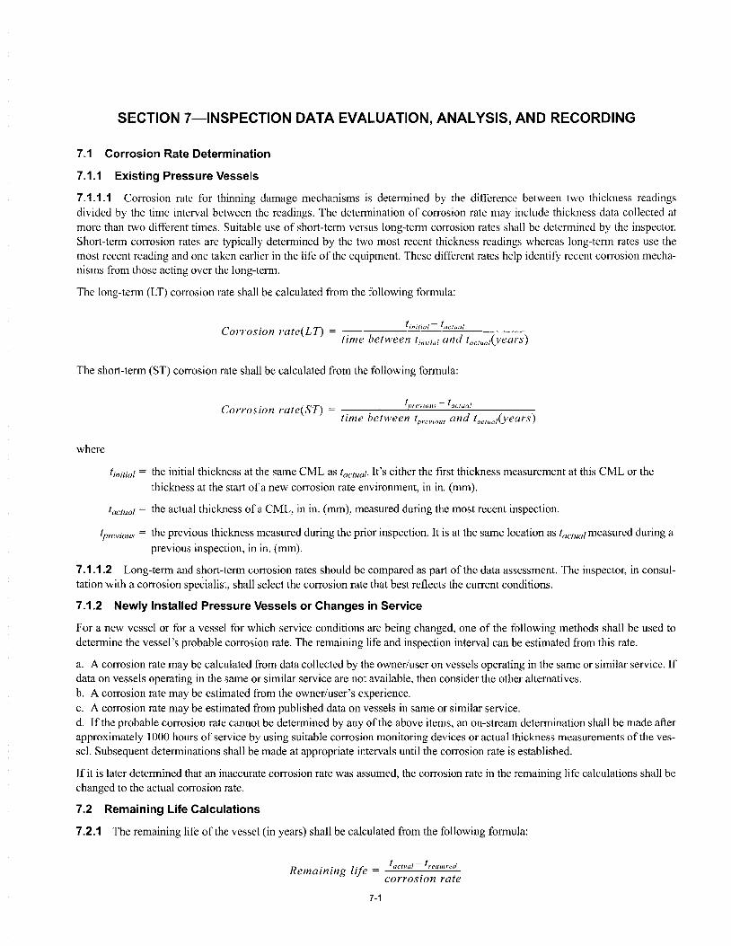
SECTION 7-INSPECTION DATA EVALUATION, ANALYSIS, AND RECORDING
7.1 Corrosion Rate Determination
7.1.1 Existing Pressure Vessels
7.1.1.1 Corrosion rate for thinning damage mechanisms is determined by the difference between two thickness readings divided by the time interval between the readings. The determination of corrosion rate may include thickness data collected at more than two different times. Suitable use of short-term versus long-term corrosion rates shall be determined by the inspector. Short-term corrosion rates are typically determined by the two most recent thickness readings whereas long-term rates usc the most recent reading and one taken earlier in the life of the equipment. These different rates hclp identifY recent corrosion mechanisms from those acting over the long-term.
The long-term (LT) corrosion rate shall be calculated from the following formula:
Corrosion rate(LT) = time between tinitial and taelual(yearS)
tinitial- factual
The short-term (ST) corrosion rate shall be calculated from the following formula:
where
Corrosion rate(ST) = [previous - toe/uol time between [previous and lae,ua,(years)
tinitial = the initial thickness at the same CML as tactual. It's either the fIrst thickness measurement at this CML or the thickness at the start ofa new corrosion rate environment, in in. (mm).
tactual = the actual thickness of a CML, in in. (mm), measured during the most recent inspection.
tprevious = the previous thickness measured during the prior inspection. It is at the same location as tactual measured during a previous inspection, in in. (mm).
7.1.1.2 Long-term and short-term corrosion rates should be compared as part of the data assessment. The inspector, in consultation with a corrosion spe~ialist, shall select the corrosion rate that best reflects the current conditions.
7.1.2 Newly Installed Pressure Vessels or Changes in Service
For a new vessel or for a vessel for which service conditions are being changed, one of the following methods shall be used to determine the vessel's probable corrosion rate. The remaining life and inspection interval can be estimated from this rate.
a. A corrosion rate may be calculated from data collected by the owner/user on vessels operating in the same or similar service. If data on vessels operating in the same or similar service are not available, then consider the other alternatives. b. A corrosion rate may be estimated from the owner/user's experience. c. A corrosion rate may be estimated from published data on vessels in same or similar service. d. If the probable corrosion rate cannot be determined by any of the above items, an on-stream determination shall be made after approximately 1000 hours of service by using suitable corrosion monitoring devices or actual thickness measurements of the vessel. Subsequent determinations shall be made at appropriate intervals until the corrosion rate is established.
If it is later determined that an inaccurate corrosion rate was assumed, the corrosion rate in the remaining Ii fe calculations shall be changed to the actual corrosion rate.
7.2 Remaining Life Calculations
7.2.1 The remaining life of the vessel (in years) shall be calculated from the following formula:
R .. 1;'1' t oclual - t required emaznzng IJe = . corrosIOn rate
7-1
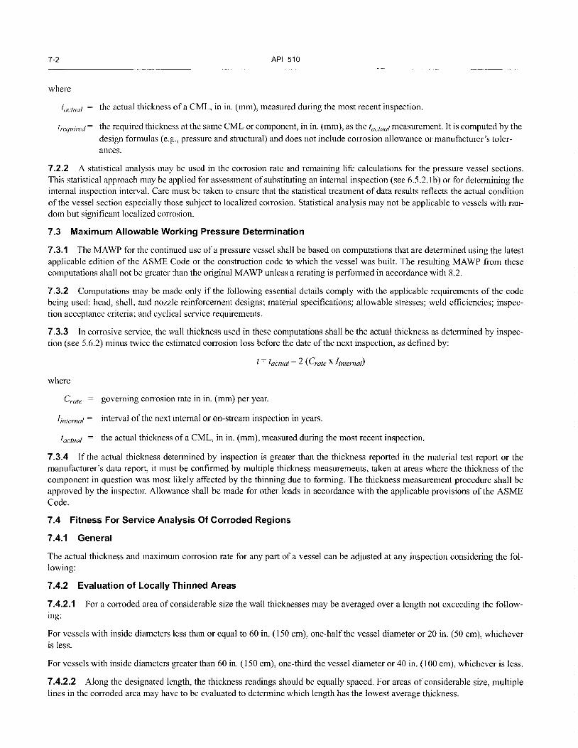
7-2 API 510
where
taclual the actual thickness of a CML, in in. (mm), measured during the most recent inspection.
trequired = the required thickness at the same CML or component, in in. (mm), as the taclual measurement. It is computed by the design formulas (e.g., pressure and structural) and does not include corrosion allowance or manufacturer's tolerances.
7.2.2 A statistical analysis may be used in the corrosion rate and remaining life calculations for the pressure vessel sections. This statistical approach may be applied for assessment of substituting an intemal inspection (see 6.5.2.1b) or for determining the internal inspection interval. Care must be taken to ensure that the statistical treatment of data results reflects the actual condition of the vessel section especially those subject to localized corrosion. Statistical analysis may not be applicable to vessels with random but significant localized corrosion.
7.3 Maximum Allowable Working Pressure Determination
7.3.1 The MA WP for the continued use of a pressure vessel shall be based on computations that are determined using the latest applicable edition of the ASME Code or the construction code to which the vessel was built. The resulting MA WP from these computations shall not be greater than the original MAWP unless a rerating is performed in accordance with 8.2.
7.3.2 Computations may be made only if the following essential details comply with the applicable requirements of the code being used: head, shell, and nozzle reinforcement designs; material specifications; allowable stresses; weld efficiencies; inspection acceptance criteria; and cyclical service requirements.
7.3.3 In corrosive service, the wall thickness used in these computations shall be the actual thickness as determined by inspection (see 5.6.2) minus twice the estimated corrosion loss before the date of the next inspection, as defined by:
t = tactual- 2 (Crate X linternaD
where
Crate governing corrosion rate in in. (mm) per year.
linternal = interval of the next internal or on-stream inspection in years.
tactual = the actual thickness of a CML, in in. (mm), measured during the most recent inspection.
7.3.4 If the actual thickness determined by inspection is greater than the thickness reported in the material test report or the manufacturer's data report, it must be confirmed by multiple thickness measurements, taken at areas where the thickness of the component in question was most likely affected by the thinning due to forming. The thickness measurement procedure shall be approved by the inspector. Allowance shall be made for other loads in accordance with the applicable provisions of the ASME Code.
7.4 Fitness For Service Analysis Of Corroded Regions
7.4.1 General
The actual thickness and maximum corrosion rate for any part of a vessel can be adjusted at any inspection considering the following:
7.4.2 Evaluation of Locally Thinned Areas
7.4.2.1 For a corroded area of considerable size the wall thicknesses may be averaged over a length not exceeding the following:
For vessels with inside diameters less than or equal to 60 in. (150 cm), one-half the vessel diameter or 20 in. (50 cm), whichever is less.
For vessels with inside diameters greater than 60 in. (150 cm), one-third the vessel diameter or 40 in. (100 cm), whichever is less.
7.4.2.2 Along the designated length, the thickness readings should be equally spaced. For areas of considerable size, multiple lines in the corroded area may have to be evaluated to determine which length has the lowest average thickness.

PRESSURE VESSEL INSPECTION CODE: IN-SERVICE INSPECTION, RATING, REPAIR, AND ALTERATION 7-3
7.4.2.3 If circumferential stresses govern, (typical for most vessels) the thickness readings are taken along a longitudinal length. Iflongitudinal stresses govern (because of wind loads or other factors), the thickness readings are taken along a circumferentiallength (an arc).
7.4.2.4 When performing corrosion averaging near a nozzle, the designated length shall not extend within the limits of the reinforcement as defined in the construction code.
7.4.2.5 When performing remaining life calculations in 7.2, the lowest average of any length in the corroded area is substituted
for tactual.
7.4.3 Evaluation of Pitting
During the current inspection, widely scattered pits may be ignored as long as all of the following are true:
a. The remaining thickness below the pit is greater than one-half the required thickness (' /2 (required).
b. The total area of the pitting that is deeper than the corrosion allowance does not exceed 7 in.2 (45 cm2) within any 8-in. (20-cm) diameter circle.
c. The sum of the pit dimensions that is deeper than the corrosion allowance along any straight 8-in. (20-cm) line does not exceed 2 in. (5 cm).
7.4.4 Alternative Evaluation Methods for Thinning
7.4.4.1 An alternative to the procedures in 7.4.2 and 7.4.3, components with thinning below the required thickness may be evaluated by employing the design by analysis methods of either ASME Section VIII, Division 2, Appendix 4, or APT 579 Appendix B. These methods may also be used to evaluate blend ground areas where defects have been removed. It is important to ensure that there are no sharp comers in blend ground areas to minimize stress concentration effects.
7.4.4.2 When using ASME Section VIII, Division 2, Appendix 4, the stress value used in the original pressure vessel design shall be substituted for the Sm value of Division 2 ifthe design stress is less than or equal to 2/3-specified minimum yield strength (SMYS) at temperature. If the original design stress is greater than 2/3-specified minimum yield strength at temperature, then 2/3-
specified minimum yield strength shall be substituted for Sm. When this approach is to be used, an engineer shall perform this analysis.
7.4.5 Joint Efficiency Adjustments
When the vessel surface away from a weld is corroded and the joint efficiency is less than 1.0, an independent calculation using the appropriate weld joint factor (typically 1.0) can be made. For this calculation, the surface at a weld includes 1 in. (2.5 cm) on either side of the weld (measured from the toe) or twice the required thickness on either side of the weld, whichever is greater.
7.4.6 Corroded Areas in Vessel Heads
7.4.6.1 The required thickness at corroded areas of ellipsoidal and tori spherical heads can be determined as follows:
a. In the knuckle region of the head, use the appropriate head formula in the construction code.
b. In the central portion of the head, use the hemi-spherical head formula in the construction code. The central portion of the head is defined as the center of the head with a diameter equal to 80% of the shell diameter.
7.4.6.2 For torispherical heads, the radius to use in the hemi-spherical head formula is the crown radius (equal to the outside diameter of the shell for standard torispherical heads, though other radii have been permitted).
7.4.6.3 For ellipsoidal heads, the radius to use in the hemi-spherical head formula shall be the equivalent spherical radius KID, where D is the shell diameter (equal to the inside diameter) and K1 is given in Table 7-1. In Table 7-1, h is one-half the length of the minor axis [equal to the inside depth of the ellipsoidal head measured from the tangent line. For many ellipsoidal heads, Dl2h equals 2.0.
7.5 API 579 Fitness-for-Service Evaluations
Pressure containing components found to have damage that could affect their load carrying capability (pressure loads and other applicable loads, e.g., weight, wind, etc., per API 579) shall be evaluated for continued service. Fitness-for-service evaluations,

7-4 API 510
Table 7-1-Values of Spherical Radius Factor K,
D/2h
3.0
2.8
2.6
2.4 2.2
2.0
1.8
1.6
1.4 1.2 1.0
1.36 1.27
1.18 1.08
0.99
0.90
0.81
0.73
0.65
0.57 0.50
Note: The equivalent spherical radius equals K1 D; the axis ratio equals D/2h. Interpolation is pennitted for intennediate values.
such as those documented in API 579, may be used for this evaluation and must be applicable to the specific damage observed. The following techniques may be used as an alternative to the evaluation techniques in 7.4.
a. To evaluate metal loss in excess of the corrosion allowance, a fitness-for-service assessment may be performed in accordance with API 579, Parts 4 or 5, as applicable. This assessment requires the use of a future corrosion allowance, which shall be established based on Section 6 of this inspection code. b. To evaluate blisters and laminations, a fitness-for-service assessment should be performed in accordance with API 579, Part 7. In some cases, this evaluation will require the use of a future corrosion allowance, which shall be established based on Section 6 of this inspection code. c. To evaluate weld misalignment and shell distortions, a fitness-for-service assessment should be performed in accordance with API 579, Part 8. d. To evaluate crack-like flaws, a fitness-for-service assessment should be performed in accordance with API 579, Part 9. When manual shear wave ultrasonic techniques are employed to size flaws, an industry-qualified UT shear wave examiner shall be used. e. To evaluate the effects of fire damage, a fitness-for-service assessment should be performed in accordance with API 579, Part 11.
7.6 Required Thickness Determination
The required thickness shall be based on pressure, mechanical, and structural considerations using the appropriate design formulae and code allowable stress. For services with high potential consequences if failure were to occur, the engineer should consider increasing the required thickness above the calculated minimum thickness to provide for unanticipated or unknown loadings, undiscovered metal loss, or resistance to normal abuse.
7.7 Evaluation Of Existing Equipment With Minimal Documentation
For pressure vessels that have no nameplate and minimal or no design and construction documentation, the following steps may be used to verify operating integrity:
I. Perfonn inspection to determine condition of the vessel. 2. Define design parameters and prepare drawings. 3. Perfonn design calculations based on applicable codes and standards. Do not use allowable stress values of the current ASME Code (based on design factor of3.5) for vessels designed to an edition or addendum of the AS ME Code earlier than the 1999 Addenda and was not designed to Code Case 2290 or 2278.
See ASME Code Section VIII, Division I, Paragraph UG-10(c) for guidance on evaluation of unidentified materials. IfUG-10 (c) is not followed, then for carbon steels, use allowable stresses for SA-283 Grade C; and for alloy and nonferrous materials, use x-ray fluorescence analysis to determine material type on which to base allowable stress values.
When extent of radiography originally performed is not known, use joint factor of 0.7 for butt welds, or consider performing radiography if a higher joint factor is required. (Recognize that performing radiography on welds in a vessel with minimal or no design and construction documentation may result in the need for a fitness-for-service evaluation and significant repairs.)

PRESSURE VESSEL INSPECTION CODE: IN-SERVICE INSPECTION, RATING, REPAIR, AND ALTERATION 7-5
4. Attach a nameplate or stamping showing the maximum allowable working pressure and temperature, minimum allowable temperature, and date. 5. Perform pressure test as soon as practical, as required by code of construction used for design calculations.
7.8 Reports And Records
7.8.1 Pressure vessel owners and users shall maintain permanent and progressive records of their pressure vessels and pressurerclieving devices. Permanent records will be maintained throughout the service life of each equipment item; progressive records will be regularly updated to include new information pertinent to the operation, inspection, and maintenance history of the equipment.
7.8.2 Pressure vessel and pressure-relieving device records shall contain four types of information pertinent to mechanical integrity as follows:
a. Construction and design information. For example, equipment serial number or other identifier, manufacturer's data reports (MDRs), design specification data, vessel design calculations, pressure-relieving device sizing calculations and construction drawings. b. Inspection history. For example, inspection reports, and data for each type of inspection conducted (for example, internal, external, thickness measurements), and inspection recommendations for repair Inspection reports shall document the date of each inspection and/or examination, the date of the next scheduled inspection, the name of the person who performed the inspection and/or examination, the serial number or other identifier of the equipment inspected, a description of the inspection and/or examination performed, and the results of the inspection and/or examination. Pressure vessel RBI records should be in accordance with API 580, Section 16. c. Repair, alteration, and rerating information. For example, (1) repair and alteration forms like that shown in Appendix 0; (2) reports indicating that equipment still in-service with either identified deficiencies, temporary repairs or recommendations for repair, are suitable for continued service until repairs can be completed; and (3) rerating documentation (including rerating calculations, new design conditions, and evidence of stamping). d. Fitness-for-service assessment documentation requirements are described in API 579, Part 2.8. Specific documentation requirements for the type of flaw being assessed are provided in the appropriate part of API 579.
7.8.3 Site operating and maintenance records, such as operating conditions, including process upsets that may affect mechanical integrity, mechanical damage from maintenance should also be available to the inspector.


SECTION 8-REPAIRS, ALTERATIONS, AND RERATING OF PRESSURE VESSELS
8.1 Repairs and Alterations
All repairs and alterations shall be performed by a repair organization in accordance with the applicable principles of the ASME Code, or the applicable construction or repair code. Repairs to pressure-relieving devices should follow API 576. The repair organization must follow all applicable safety requirements as designated in 5.3.
8.1.1 Authorization
All repair and alteration work must be authorized by the inspector before the work is started by a repair organization. Authorization for alterations to pressure vessels that comply with ASME Section VIII, Divisions I and 2, and for repairs to pressure vessels that comply with ASME Section VIII, Division 2, may not be given until an engineer has also authorized the work. The inspector will designate the hold points that are required. The inspector may give prior general authorization for limited or routine repairs on a specific vessel provided the inspector is satisfied with the competency of the repair organization and the repairs are the kind that will not require a pressure test (e.g. weld overlay of pitting on a vessel that does not require post-weld heat treatment).
8.1.2 Approval
8.1.2.1 Before any repairs or alterations are performed, all proposed methods of design, execution, materials, welding procedures, NDE, and testing must be approved by the inspector and, if an alteration, by an engineer. The inspector may establish hold points to be implemented during the work execution.
8.1.2.2 The inspector shall approve all specified repair and alteration work at designated hold points and after completion of the work in accordance with the repair plan.
8.1.3 Design
New vessel nozzles, connections, or replacement parts must meet the design requirements of the applicable construction code. The design of replacement parts and new nozzles shall employ the same allowable stress criteria as used for the vessel design. Design, location, and method of attachment must comply with applicable requirements of the applicable construction code. When damage to parts of a vessel is so great that repairs cannot restore them to design requirements, the parts shall be replaced. An engineer shall approve all nozzle installations.
8.1.4 Material
The material used in making repairs or alterations shall conform to the applicable construction code. Material markings, material control practices and material test reports (MTRs) provided to owner/user must comply with the applicable construction code. Materials used for welded repairs and alterations shall be of known weldable quality and be compatible with the original material. Carbon or alloy steel with carbon content over 0.35% shall not be welded.
8.1.5 Defect Repairs
Repairs to defects found in pressure vessel components may be made by several techniques often dependent upon the size and nature of the defect, the materials of construction, and the design requirements of the pressure vessel. Repair techniques can be classified as permanent or temporary depending upon their design and conformance to the applicable construction code.
8.1.5.1 Temporary Repairs
8.1.5.1.1 General
Temporary repairs should be removed and replaced with suitable permanent repairs at the next available maintenance opportunity. Temporary repairs may remain in place for a longer period of time only if evaluated, approved, and documented by the engineer and inspector. Documentation oftemporary repairs should include:
a. Location of the temporary repair, b. Specific details about the repair, e.g. material of construction, thickness, size of welds, NDE performed. c. Details of analyses performed, d. Requirements for future inspections, and e. Due date for installing permanent repair.
8-1
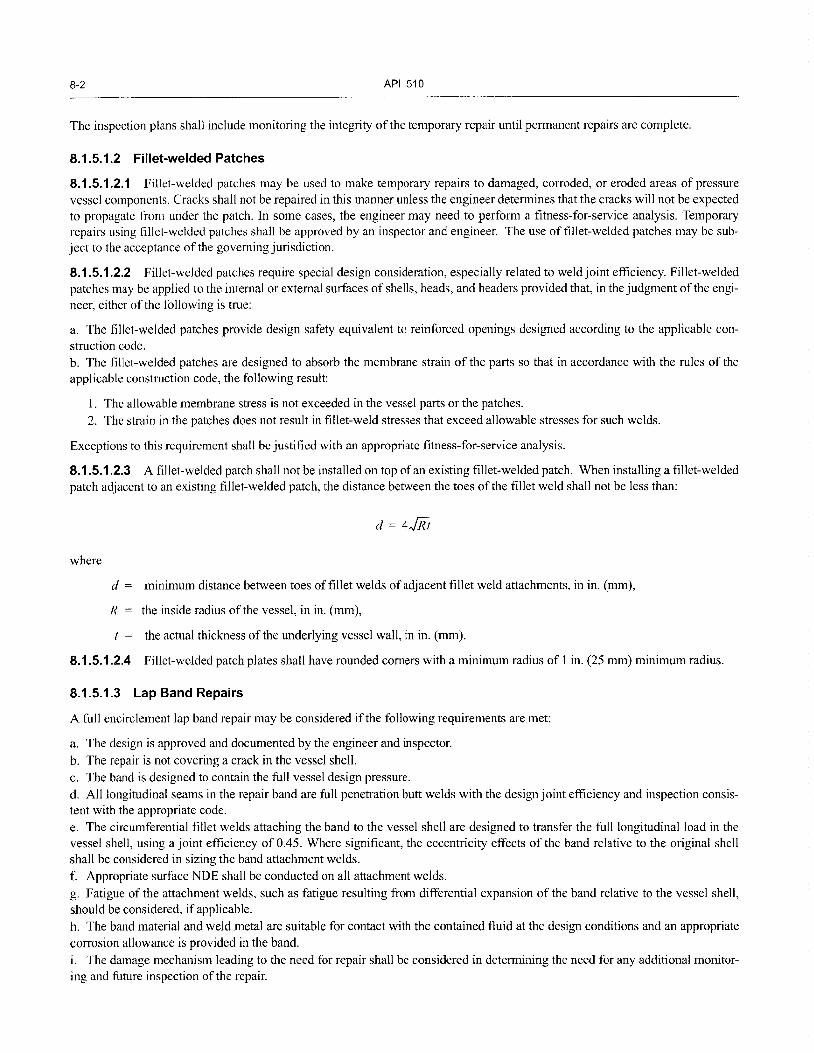
8-2 API 510
The inspection plans shall include monitoring the integrity of the temporary repair until permanent repairs are complete.
8.1.5.1.2 Fillet-welded Patches
8.1.5.1.2.1 Fillet-welded patches may be used to make temporary repairs to damaged, corroded, or eroded areas of pressure vessel components. Cracks shall not be repaired in this manner unless the engineer determines that the cracks will not be expected to propagate from under the patch. In some cases, the engineer may need to perform a fitness-for-service analysis. Temporary repairs using fillet-welded patches shall be approved by an inspector and engineer. The use of fillet-welded patches may be subject to the acceptance of the governing jurisdiction.
8.1.5.1.2.2 Fillet-welded patches require special design consideration, especially related to weld joint efficiency. Fillet-welded patches may be applied to the internal or external surfaces of shells, heads, and headers provided that, in the judgment of the engineer, either of the following is true:
a. The fillet-welded patches provide design safety equivalent to reinforced openings designed according to the applicable construction code. b. The fillet -welded patches are designed to absorb the membrane strain of the parts so that in accordance with the rules of the applicable construction code, the following result:
1. The allowable membrane stress is not exceeded in the vessel parts or the patches.
2. The strain in the patches does not result in fillet-weld stresses that exceed allowable stresses for such welds.
Exceptions to this requirement shall be justified with an appropriate fitness-for-service analysis.
8.1.5.1.2.3 A fillet-welded patch shall not be installed on top of an existing fillet-welded patch. When installing a fillet-welded patch adjacent to an existing fillet-welded patch, the distance between the toes ofthe fillet weld shall not be less than:
where
d = minimum distance between toes of fillet welds of adjacent fillet weld attachments, in in. (mm),
R the inside radius of the vessel, in in. (mm),
the actual thickness of the underlying vessel wall, in in. (mm).
8.1.5.1.2.4 Fillet-welded patch plates shall have rounded comers with a minimum radius of 1 in. (25 rom) minimum radius.
8.1.5.1.3 Lap Band Repairs
A full encirclement lap band repair may be considered if the following requirements are met:
a. The design is approved and documented by the engineer and inspector.
b. The repair is not covering a crack in the vessel shell. c. The band is designed to contain the full vessel design pressure. d. All longitudinal seams in the repair band are full penetration butt welds with the design joint efficiency and inspection consistent with the appropriate code. e. The circumferential fillet welds attaching the band to the vessel shell are designed to transfer the full longitudinal load in the vessel shell, using a joint efficiency of 0.45. Where significant, the eccentricity effects of the band relative to the original shell shall be considered in sizing the band attachment welds. f. Appropriate surface NDE shall be conducted on all attachment welds.
g. Fatigue of the attachment welds, such as fatigue resulting from differential expansion of the band relative to the vessel shell, should be considered, if applicable. h. The band material and weld metal are suitable for contact with the contained fluid at the design conditions and an appropriate corrosion allowance is provided in the band. i. The damage mechanism leading to the need for repair shall be considered in determining the need for any additional monitoring and future inspection of the repair.

PRESSURE VESSEL INSPECTION CODE: IN-SERVICE INSPECTION, RATING, REPAIR, AND ALTERATION 8-3
8.1.5.1.4 Non-penetrating Nozzles
Non-penetrating nozzles (including pipe caps attached as nozzles) may be used as permanent repairs for other than cracks when the design and method of attachment comply with the applicable requirements of the appropriate code. The design and reinforcement of such nozzles shall consider the loss ofthe original shell material enclosed by the nozzle. The nozzle material shall be suitable for contact with the contained fluid at the design conditions and an appropriate corrosion allowance shall be provided. The damage mechanism leading to the need for repair shall be considered in determining the need for any additional monitoring and future inspection of the repair.
8.1.5.2 Permanent Repair
8.1.5.2.1 Typical permanent repair techniques include:
a. Excavating the defect, and blend-grinding to contour in accordance with API 579, Part 5. b. Excavating a defect and repair welding of the excavation. c. Replacing a section or the component containing the defect. d. Weld overlay of corroded area. e. Adding strip or plate lining to the interior surface.
Repairing a crack at a discontinuity, where stress concentrations are high, (e.g. crack in a nozzle-to-shell weld) should not be attempted without prior consultation with an engineer.
8.1.5.2.2 Insert Plates
Damaged or corroded shell plates may be repaired by removing a section and replacing it with an insert patch (flush patch) that meets the applicable code. Insert patches may be used if the following requirements are met:
a. Full-penetration groove welds are provided. b. The welds are radiographed in accordance with the applicable construction code. Ultrasonic examination, by an industry-qualified UT shear wave examiner, may be substituted for the radiography if the NDE procedures are approved by the inspector. c. All insert plate comers that do not extend to an existing longitudinal or horizontal weld shall be rounded having a I in. (25 mm) minimum radius. Weld proximity to existing welds shall be reviewed by the engineer.
8.1.5.3 Filler Metal Strength for Overlay and Repairs to Existing Welds
8.1.5.3.1 The filler metal used for weld repairs should have minimum specified tensile strength equal to or greater than the minimum specified tensile strength of the base metal.
8.1.5.3.2 If a filler metal is used that has a minimum specified tensile strength lower than the minimum specified tensile strength of the base metal, the compatibility of the filler metal chemistry with the base metal chemistry shall be considered regarding weldability and service damage. In addition, all of the following shall be met:
a. The repair thickness shall not be more than 50% of the required thickness of the base metal (this excludes corrosIOn allowance). b. The thickness of the repair weld shall be increased by a ratio of minimum specified tensile strength of the base metal and minimum specified tensile of the filler metal used for the repair.
where
Ttill thickness of repair weld metal, in in. (mm),
d depth of base metal lost by corrosion and weld preparation, in in. (mm),
Sbase base metal tensile strength, in ksi (MPa),
Still filler metal tensile strength, in ksi (MPa).
8-4 API 510
c. Thc increased thickness of the repair shall have rounded comers and shall be blended into the base metal using a 3-to-l taper. d. The repair shall be made with a minimum of two passes.
8.1.5.4 Repairs to Stainless Steel Weld Overlay and Cladding
8.1.5.4.1 The repair procedure(s) to restore removed, corroded, or missing clad or overlay areas shall be reviewed and approved by the engineer and inspector before implementation.
8.1.5.4.2 Consideration shall be given to important factors that may affect the repair plan. These factors include stress level, P number of base material, service environment, possible previously dissolved hydrogen, type of lining, deterioration of base metal properties (by temper embrittlement of chromium-molybdenum alloys), minimum pressurization temperatures, and a need for future periodic examination.
8.1.5.4.3 For equipment exposed to atomic hydrogen migration in the base metal (operates in hydrogen service at an elevated temperature or has exposed base metal areas open to corrosion) these additional factors must be considered by the engineer when developing the repair plan:
a. Outgassing base metal. b. Hardening of base metal due to welding, grinding, or arc gouging. c. Preheat and interpass temperature control. d. Postweld heat treatment to reduce hardness and restore mechanical properties.
These repairs shall be monitored by an inspector to assure compliance to repair requirements. After cooling to ambient temperatures, the repair shall be inspected by the PT method, according to ASME Code, Section VIII: Division I, Pressure Vessels, Appendix 8.
8.1.5.4.4 For vessels constructed with P-3, P-4, or P-5 base materials, the base metal in the area of repair should also be examined for cracking by the ultrasonic examination in accordance with ASME Code, Section V, Article 4, Paragraph T-473. This inspection is most appropriately accomplished following a delay of at least 24 hours after completed repairs for alloys that could be affected by delayed cracking.
8.1.6 Welding and Hot Tapping
8.1.6.1 General
All repair and alteration welding shall be in accordance with the applicable requirements of the AS ME Code or the applicable construction or repair code, except as permitted in 8.1.5.3. Refer to API 582 for additional welding considerations.
Refer to API 220 I when making on-stream welds.
8.1.6.2 Procedures, Qualifications and Records
8.1.6.2.1 The repair organization shall use welders and welding procedures that are qualified in accordance with the applicable requirements of the construction code e.g. Section IX. Welders must weld within their ranges qualified on the WPQ(s).
8.1.6.2.2 The repair organization shall maintain records of its qualified welding procedures and its welding performance qualifications. These records shall be available to the inspector before the start of welding.
8.1.6.2.3 API 577 provides guidance on how to review of weld procedures and welding performance qualifications and how to respond to welding non-conformances.
8.1.6.3 Preheating
Preheat temperature used in making welding repairs shall be in accordance with the applicable code and qualified welding procedure. Exceptions must be approved by the engineer. The inspector should assure that the minimum preheat temperature is measured and maintained.
8.1.6.4 Postweld Heat Treatment
PWHT of pressure vessel repairs or alterations should be made using the relevant requirements of the ASME code, the applicable construction code, or an approved alternative PWHT procedure defined in 8.1.6.4.2.

PRESSURE VESSEL INSPECTION CODE: IN-SERVICE INSPECTION, RATING, REPAIR, AND ALTERATION 8-5
8.1.6.4.1 Local Postweld Heat Treatment
Local PWHT may be substituted for 360-degree banding on local repairs on all materials, provided that the following precautions are taken and requirements are met:
a. The application is reviewed, and a procedure is developed by an engineer experienced in the appropriate engineering specialties. b. The suitability of the procedure shall be evaluated considering the following factors:
1. Base metal thickness. 2. Decay thermal gradients. 3. Material properties (hardness, constituents, strength, etc.). 4. Changes due to local postweld heat treatment. 5. The need for full penetration welds. 6. Surface and volumetric examinations after local postweld heat treatment. 7. The overall and local strains and distortions resulting from the heating of a local restrained area of the pressure vessel shell.
c. A preheat of300°F (I 50°C) or higher, as specified by specific welding procedures, is maintained during welding. d. The required local postweld heat treatment temperature shall be maintained for a distance of not less than two times the base metal thickness measured from the toe of the weld. The local postweld heat treatment temperature shall be monitored by a suitable number of thermocouples (at least two). When determining the number of thermocouples necessary, the size and shape ofthe area being heat treated should be considered. e. Controlled heat shall be applied to any nozzle or any attachment within the local postweld heat treatment area. f. When PWHT is performed for environmental-assisted cracking resistance, a metallurgical review shall be conducted to assess whether the procedure is acceptable.
8.1.6.4.2 Preheat or Controlled Deposition Welding Methods as Alternatives to Postweld Heat Treatment
8.1.6.4.2.1 General
8.1.6.4.2.1.1 Preheat and controlled deposition welding, as described in 8.1.6.4.2.2 and 8.1.6.4.2.3, may be used in lieu of PWHT where PWHT is inadvisable or mechanically unnecessary. Prior to using any alternative method, a metallurgical review conducted by an engineer shall be performed to assure the proposed alternative is suitable for the application. The review should consider factors such as the reason for the original PWHT of the equipment, susceptibility to stress corrosion cracking, stresses in the location of the weld, susceptibility to high temperature hydrogen attack, susceptibility to creep, etc.
8.1.6.4.2.1.2 Selection of the welding method used shall be based on the rules of the construction code applicable to the work planned along with technical consideration of the adequacy of the weld in the as-welded condition at operating and pressure test conditions.
8.1.6.4.2.1.3 When reference is made in this section to materials by the AS ME designation, P-Number and Group Number, the requirements of this section apply to the applicable materials of the original code of construction, either ASME or other, which conform by chemical composition and mechanical properties to the ASME P-Number and Group Number designations.
8.1.6.4.2.1.4 Vessels constructed of steels other than those listed in 8.1.6.4.2.2 and 8.1.6.4.2.3, that initially required PWHT, shall be postweld heat treated if alterations or repairs involving pressure boundary welding are performed. When one of the following methods is used as an alternative to PWHT, the PWHT joint efficiency factor may be continued if the factor has been used in the currently rated design.
8.1.6.4.2.2 Preheating Method (Notch Toughness Testing Not Required)
8.1.6.4.2.2.1 The preheating method, when performed in lieu of PWHT, is limited to the following materials and weld processes:
a. The materials shall be limited to P-No. 1, Group 1,2, and 3, and to P-No. 3, Group I and 2 (excluding Mn-Mo steels in Group 2). b. The welding shall be limited to the shielded-metal-arc welding (SMAW), gas-metal-arc welding (GMAW), and gas-tungstenarc welding (GfAW) processes.
8.1.6.4.2.2.2 The preheat method shall be performed as follows:
8-6 API 510
The weld area shall be preheated and maintained at a minimum temperature of 300DF (lSO°C) during welding. The 300DF (ISO°C) temperature should be checked to assure that 4 in. (100 mm) of the material or four times the material thickness (whichever is greater) on each side of the groove is maintained at the minimum temperature during welding. The maximum interpass temperature shall not exceed 600DF (3IS0C). When the weld does not penetrate through the full thickness of the material, the minimum preheat and maximum interpass temperatures need only be maintained at a distance of 4 in. (100 mm) or four times the depth of the repair weld, whichever is greater on each side of the joint.
Note: Notch toughness testing is not required when using this preheat method in lieu ofPWHT.
8.1.6.4.2.3 Controlled-deposition Welding Method (Notch Toughness Testing Required)
The controlled-deposition welding method may be used in lieu ofPWHT in accordance with the following:
a. Notch toughness testing, such as that established by ASME Code Section VIII: Division I, parts UG-84 and UCS-66, is necessary when impact tests are required by the original code of construction or the construction code applicable to the work planned. b. The materials shall be limited to P-No. I, P-No. 3, and P-No. 4 steels. c. The welding shall be limited to the shielded-metal-arc welding (SMA W), gas-metal-arc welding (GMA W), and gas-tungstenarc welding (GTAW) processes. d. A weld procedure specification shall be developed and qualified for each application. The welding procedure shall define the preheat temperature and interpass temperature and include the post heating temperature requirement in f(S). The qualification thickness for the test plates and repair grooves shall be in accordance with Table 8-1.
The test material for the welding procedure qualification shall be of the same material specification (including specification type, grade, class and condition of heat treatment) as the original material specification for the repair. If the original material specification is obsolete, the test material used should conform as much as possible to the material used for construction, but in no case shall the material be lower in strength or have a carbon content of more than 0.3S%.
e. When impact tests are required by the construction code applicable to the work planned, the PQR shall include sufficient tests to determine if the toughness of the weld metal and the heat-affected zone ofthe base metal in the as-welded condition is adequate at the minimum design metal temperature (such as the criteria used in ASME Code Section VIII: Division I, parts UG-S4 and DCS 66). If special hardness limits are necessary (for example, as set forth in NACE RP 0472 and MR 0103) for corrosion resistance, the PQR shall include hardness tests as well. f. The WPS shall include the following additional requirements:
I. The supplementary essential variables of ASME Code, Section IX, Paragraph QW-2S0, shall apply. 2. The maximum weld heat input for each layer shall not exceed that used in the procedure qualification test. 3. The minimum preheat temperature for welding shall not be less than that used in the procedure qualification test. 4. The maximum interpass temperature for welding shall not be greater than that used in the procedure qualification test. S. The preheat temperature shall be checked to assure that 4 in. (100 mm) of the material or four times the material thickness (whichever is greater) on each side of the weld joint will be maintained at the minimum temperature during welding. When the weld does not penetrate through the full thickness of the material, the minimum preheat temperature need only be maintained at a distance of 4 in. (100 mm) or four times the depth of the repair weld, whichever is greater on each side of the joint. 6. For the welding processes in 8.1.6.4.2.3c, use only electrodes and filler metals that are classified by the filler metal specification with an optional supplemental diffusible-hydrogen designator of H8 or lower. When shielding gases are used with a process, the gas shall exhibit a dew point that is no higher than -60°F (-SO°C). Surfaces on which welding will be done shall be maintained in a dry condition during welding and free of rust, mill scale and hydrogen producing contaminants such as oil, grease and other organic materials. 7. The welding technique shall be a controlled-deposition, temper-bead or half-bead technique. The specific technique shall be used in the procedure qualification test. 8. For welds made by SMAW, after completion of welding and without allowing the weldment to cool below the minimum preheat temperature, the temperature of the weldment shall be raised to a temperature of SOO°F ± SO°F (260°C ± 30DC) for a minimum period of two hours to assist out-gassing diffusion of any weld metal hydrogen picked up during welding. This hydrogen bake-out treatment may be omitted provided the electrode used is classified by the filler metal specification with an optional supplemental diffusible-hydrogen designator of H4 (such as E701S-H4).
9. After the finished repair weld has cooled to ambient temperature, the final temper bead reinforcement layer shall be removed substantially flush with the surface of the base material.

PRESSURE VESSEL INSPECTION CODE: IN-SERVICE INSPECTION, RATING, REPAIR, AND ALTERATION 8-7
Refer to WRC Bulletin 412 for additional supporting technical information regarding controlled deposition welding.
Table 8-1-Welding Methods as Alternatives to Postweld Heat Treatment Qualification Thickness for Test Plates and Repair Grooves
Thickness T of Depth 1 of Test Repair Groove Test Coupon Groove Welded Depth Qualified Welded
<I <2 in. (50 mm) < 1 > 2 in. (50 mm)
Thickness of Base Metal Qualified
<T 2 in. (50 mm) to unlimited
a The depth of the groove used for procedure qualification must be deep enough to allow removal of the required test specimens.
8.1.7 NDE of Welds
8.1.7.1 API 577 Welding provides guidance on NDE of weld joints and weldments. Prior to welding, usually the area prepared for welding is examined using either the MT or PT examination technique to determine that no defects exist. This examination is especially important after removing cracks and other defects.
8.1.7.2 After the weld is completed, it shall be examined again by the appropriate NDE technique specified in the repair specification to determine that no defects exist using acceptance standards acceptable to the Inspector or the applicable construction code.
8.1.7.3 New welds, as part ofa repair or alteration in a pressure vessel that were originally required to be radiographed (e.g. circumferential and longitudinal welds) by the construction code, shall be radiographically examined in accordance with the construction code. In situations where it is not practical to perform radiography the accessible surfaces of each non-radiographed new weld shall be fully examined using the most appropriate NDE technique to determine that no defects exist. Where use of NDE techniques specified by the construction code is not possible or practical, alternative NDE techniques may be used provided they are approved by the engineer and inspector.
8.1.7.4 Acceptance criteria for welded repairs or alterations should be in accordance with the applicable sections of the ASME Code or another applicable vessel rating code.
8.1.8 Weld Inspection for Vessels Subject to Brittle Fracture
For vessels constructed of materials that may be subject to brittle fracture (per API RP 579, or other analysis) from either normal or abnormal service (including startup, shutdown, and pressure testing), appropriate inspection should be considered after welded repairs or alterations. Flaws, notches, or other stress risers could initiate a brittle fracture in subsequent pressure testing or service. MT and other effective surface NDE methods should be considered. Inspection techniques should be selected to detect critical flaws as determined by a fitness-for-service assessment.
8.2 Rerating
8.2.1 Rerating a pressure vessel by changing its design temperature, minimum metal design temperature, or its maximum allowable working pressure may be done only after all ofthe following requirements have been met:
a. Calculations performed by either the manufacturer or an owner/user engineer (or his designated representative) experienced in pressure vessel design, fabrication, or inspection shall justify rerating. b. A rerating shall be performed in accordance with the requirements of the vessel's construction code. Alternately, calculations can be made using the appropriate formulas in the latest edition of the applicable construction Code provided all of the vessel's essential details comply with the applicable requirements of the AS ME code. If the vessel was designed to an edition or addendum of the ASME Code earlier than the 1999 Addenda and was not designed to Code Case 2290 or 2278, it may be rerated to the latest edition/addendum of the ASME Code if permitted by Figure 8-l. c. Current inspection records verify that the pressure vessel is satisfactory for the proposed service conditions and that the corrosion allowance provided is appropriate. An increase in allowable working pressure or design temperature shall be based on thickness data obtained from a recent internal or on-stream inspection. d. The vessel shall be pressure tested using the applicable testing formula from the code used to perform the rerating calculations unless either of the following is true:
8-8 API 510
I. The pressure vessel has at some time been pressure tested to a test pressure equal to or higher than the test pressure required by the rerate code; and, 2. The vessel integrity is confirmed by special nondestructive evaluation inspection techniques in lieu of testing.
e. The rerating is acceptable to the engineer.
8.2.2 The pressure vessel rerating will be considered complete when the inspector witnesses the attachment of an additional nameplatc or additional stamping that carries the information in Figure 8-1.
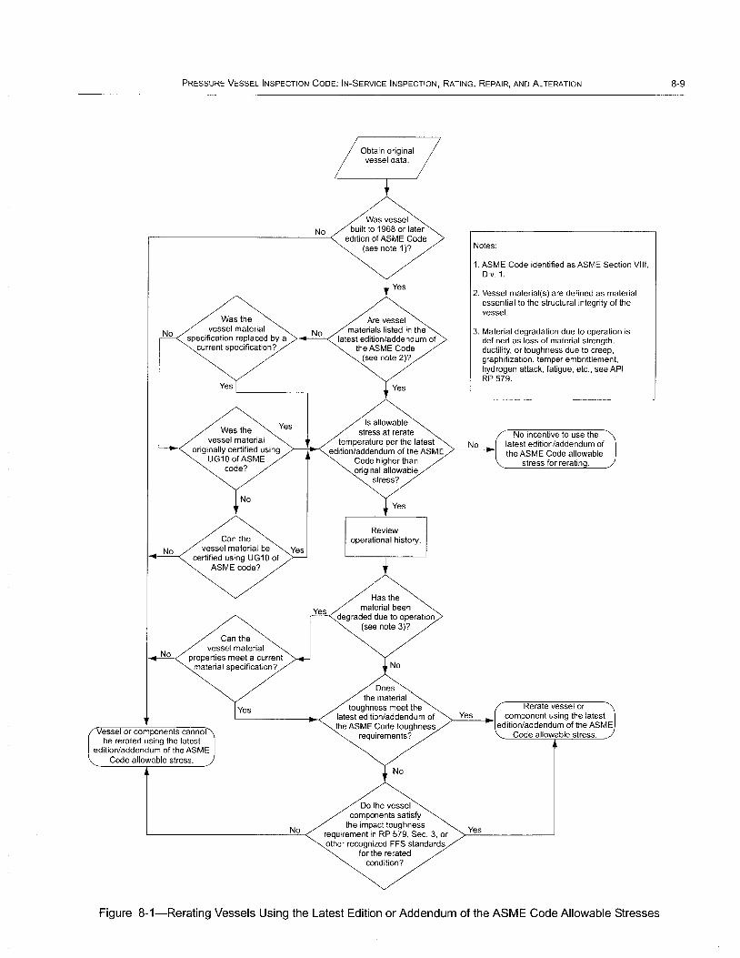
PRESSURE VESSEL INSPECTION CODE: IN-SERVICE INSPECTION, RATING, REPAIR, AND ALTERATION
No
Was the
Obtain original vessel data.
Was vessel built to 1968 or later
edition of ASME Code (see note 1)?
Yes
Notes:
1. ASME Code identified as ASME Section VIII, Div.1.
2. Vessel material(s) are defined as material essential to the structural integrity of the vessel.
No vessel material No specification replaced by a '>-_=-<'
current specification?
Are vessel materials listed in the
latest edition/addendum of the ASME Code
3. Material degradation due to operation is defined as loss of material strength, ductility, or toughness due to creep, graphitization, temper embrittlement, hydrogen attack, fatigue, etc., see API RP 579.
Yes "--------,
Was the Yes
vessel material originally certified using
UG100fASME code?
Can the
No vessel material be Yes certified using UG 1 0 of
ASME code?
Can the vessel material
properties meet a current material specification?
esse I or components cannot be rerated using the latest
edition/addendum of the ASME Code allowable stress.
Yes
No
(see note 2)?
Yes
Is allowable stress at rerate
temperature per the latest No edition/addendum of the ASME ~--'=-J~
Code higher than
Yes
original allowable stress?
Yes
Review operational history.
Has the material been
degraded due to operation (see note 3)7
No
Does the material
toughness meet the latest edition/addendum of the ASME Code toughness
requirements?
No
Do the vessel components satisfy
the impact toughness requirement in RP 579, Sec. 3, or other recognized FFS standards
for the rerated condition?
Yes
Yes
No incentive to use the latest edition/addendum of the ASME Code allowable
stress for rerating.
Rerate vessel or component using the latest
edition/addendum of the ASME Code allowable stress.
Figure 8-1-Rerating Vessels Using the Latest Edition or Addendum of the ASME Code Allowable Stresses
8-9

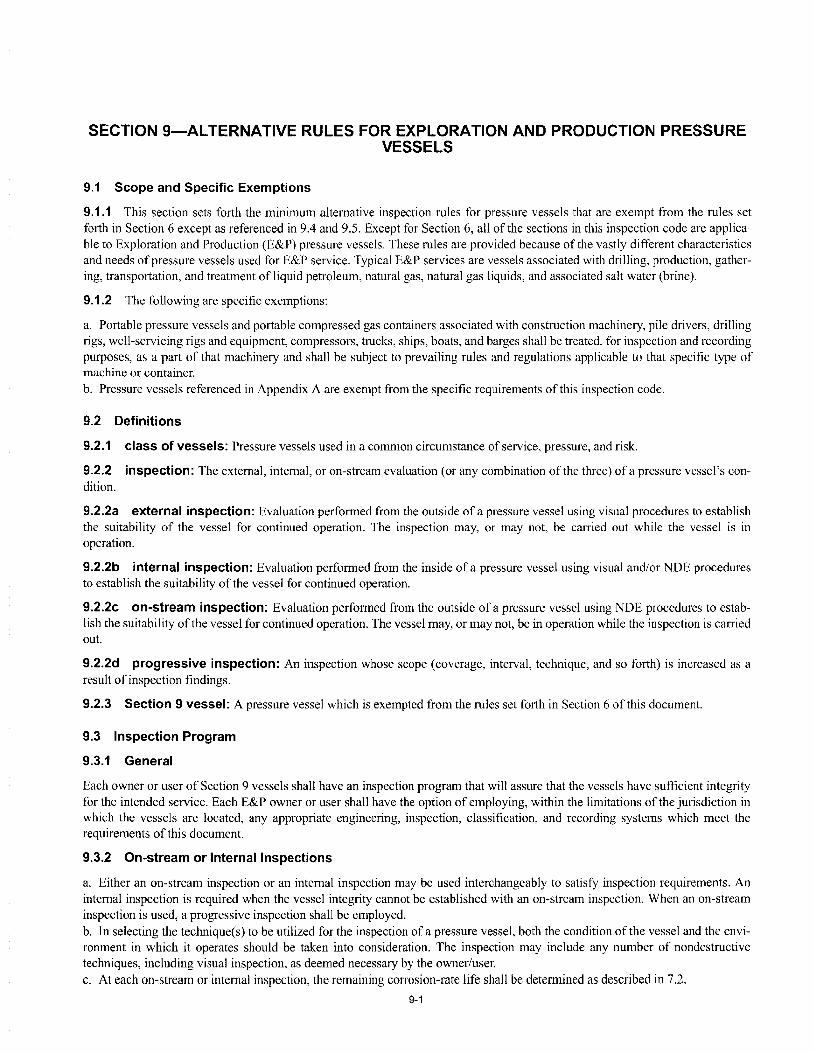
SECTION 9-AL TERNATIVE RULES FOR EXPLORATION AND PRODUCTION PRESSURE VESSELS
9.1 Scope and Specific Exemptions
9.1.1 This section sets forth the minimum alternative inspection rules for pressure vessels that are exempt from the rules set forth in Section 6 except as referenced in 9.4 and 9.5. Except for Section 6, all of the sections in this inspection code are applicable to Exploration and Production (E&P) pressure vessels. These rules are provided because of the vastly different characteristics and needs of pressure vessels used for E&P service. Typical E&P services are vessels associated with drilling, production, gathering, transportation, and treatment of liquid petroleum, natural gas, natural gas liquids, and associated salt water (brine).
9.1.2 The following are specific exemptions:
a. Portable pressure vessels and portable compressed gas containers associated with construction machinery, pile drivers, drilling rigs, well-servicing rigs and equipment, compressors, trucks, ships, boats, and barges shall be treated, for inspection and recording purposes, as a part of that machinery and shall be subject to prevailing rules and regulations applicable to that specific type of machine or container. b. Pressure vessels referenced in Appendix A are exempt from the specific requirements of this inspection code.
9.2 Definitions
9.2.1 class of vessels: Pressure vessels used in a common circumstance of service, pressure, and risk.
9.2.2 inspection: The external, internal, or on-stream evaluation (or any combination of the three) of a pressure vessel's condition.
9.2.2a external inspection: Evaluation performed from the outside of a pressure vessel using visual procedures to establish the suitability of the vessel for continued operation. The inspection may, or may not, be carried out while the vessel is in operation.
9.2.2b internal inspection: Evaluation performed from the inside of a pressure vessel using visual and/or NDE procedures to establish the suitability ofthe vessel for continued operation.
9.2.2c on-stream inspection: Evaluation performed from the outside ofa pressure vessel using NDE procedures to establish the suitability of the vessel for continued operation. The vessel may, or may not, be in operation while the inspection is carried out.
9.2.2d progressive inspection: An inspection whose scope (coverage, interval, technique, and so forth) is increased as a result of inspection findings.
9.2.3 Section 9 vessel: A pressure vessel which is exempted from the rules set forth in Section 6 of this document.
9.3 Inspection Program
9.3.1 General
Each owner or user of Section 9 vessels shall have an inspection program that will assure that the vessels have sufficient integrity for the intended service. Each E&P owner or user shall have the option of employing, within the limitations of the jurisdiction in which the vessels are located, any appropriate engineering, inspection, classification, and recording systems which meet the requirements of this document.
9.3.2 On-stream or Internal Inspections
a. Either an on-stream inspection or an internal inspection may be used interchangeably to satisfy inspection requirements. An internal inspection is required when the vessel integrity cannot be established with an on-stream inspection. When an on-stream inspection is used, a progressive inspection shall be employed. b. In selecting the technique(s) to be utilized for the inspection of a pressure vessel, both the condition of the vessel and the environment in which it operates should be taken into consideration. The inspection may include any number of nondestructive techniques, including visual inspection, as deemed necessary by the owner/user. c. At each on-stream or internal inspection, the remaining corrosion-rate life shall be determined as described in 7.2.
9-1

9-2 API 510
9.3.3 Remaining Corrosion Rate Life Determination
9.3.3.1 For a new vessel, a vessel for which service conditions are being changed, or existing vessels, the remaining corrosion rate life shall be determined for each vessel or estimated for a class of vessels based on the following formula:
where
Remaining life = tacluul- trequired
corrosion rate
fac/ual the actual thickness, in in. (mm), measured at the time of inspection for a given location or component.
trequired = the required thickness, in in. (mm), at the same location or component as the tactual measurement, obtained by one of the following methods:
a. The nominal thickness in the uncorroded condition, less the specified corrosion allowance. b. The original measured thickness, if documented, in the uncorroded condition, less the specified corrosion allowance. c. Calculations in accordance with the requirements of the construction code to which the pressure vessel was built, or by computations that are determined using the appropriate formulas in the latest edition of the ASME Code, if all of the essential details comply with the applicable requirements of the code being used.
corrosionrate= loss of metal thickness, in in. (mm), per year. For vessels in which the corrosion rate is unknown, the corrosion ratc shall be determined by one of the following methods:
I. A corrosion rate may be calculated from data collected by the owner or user on vessels in the same or similar service. 2. If data on vessels providing the same or similar service is not available, a corrosion rate may be estimated from the owner's or user's experience or from published data on vessels providing comparable service. 3. If the probable corrosion rate cannot be determined by either item a or b, on-stream determination shall be made after approximately 1000 hours of service by using suitable corrosion monitoring devices or actual nondestructive thickness measurements of the vessel or system. Subsequent determinations shall be made after appropriate intervals until the corrosion rate is established.
9.3.3.2 The remaining life shall be determined by an individual experienced in pressure vessel design and/or inspection. If it is determined that an inaccurate assumption has been made for either corrosion rate or thickness, the remaining life shall be increased or decreased to agree with the actual rate or thickness.
9.3.3.3 Other failure mechanisms (stress corrosion, brittle fracture, blistering, and so forth,) shall be taken into account when determining the remaining life of the vessel.
9.3.4 External Inspections
The following apply to external inspections:
a. The external visual inspection shall, at least, determine the condition of the shell, heads, nozzles, exterior insulation, supports and structural parts, pressure-relieving devices, allowance for expansion, and general alignment of the vessel on its supports. Any signs of leakage should be investigated so that the sources can be established. It is not necessary to remove insulation if the entire vessel shell is maintained at a temperature sufficiently low or sutnciently high to prevent the condensation of moisture. Refer to API 572 for guidelines on external vessel inspections. b. Buried sections of vessels shall be monitored to determine their external environmental condition. This monitoring shall be done at intervals that shall be established based on corrosion-rate information obtained during maintenance activity on adjacent connected piping of similar material, information from the interval examination of similarly buried corrosion test coupons of similar material, information from representative portions of the actual vessel, or information from a sample vessel in similar circumstances. c. Vessels that are known to have a remaining life of over 10 years or that are protected against external corrosion-for example, (1) vessels insulated effectively to preclude the entrance of moisture, (2) jacketed cryogenic vessels, (3) vessels installed in a cold box in which the atmosphere is purged with an inert gas, and (4) vessels in which the temperature being maintained is sufficiently low or sufficiently high to preclude the presence of water-do not need to have insulation removed for the external inspection; however, the condition of their insulating system or their outer jacketing, such as the cold box shell, shall be observed at least every five years and repaired if necessary.
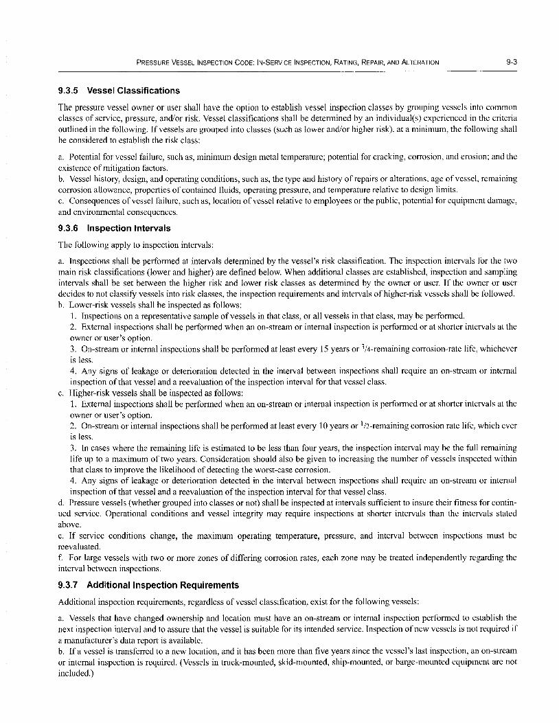
PRESSURE VESSEL INSPECTION CODE: IN-SERVICE INSPECTION, RATING, REPAIR, AND ALTERATION 9-3
9.3.5 Vessel Classifications
The pressure vessel owner or user shall have the option to establish vessel inspection classes by grouping vessels into common classes of service, pressure, and/or risk. Vessel classifications shall be determined by an individual(s) experienced in the criteria outlined in the following. Ifvessels are grouped into classes (such as lower and/or higher risk), at a minimum, the following shall be considered to establish the risk class:
a. Potential for vessel failure, such as, minimum design metal temperature; potential for cracking, corrosion, and erosion; and the existence of mitigation factors. b. Vessel history, design, and operating conditions, such as, the type and history of repairs or alterations, age of vessel, remaining corrosion allowance, properties of contained fluids, operating pressure, and temperature relative to design limits. c. Consequences of vessel failure, such as, location of vessel relative to employees or the public, potential for equipment damage, and environmental consequences.
9.3.6 Inspection Intervals
The following apply to inspection intervals:
a. Inspections shall be performed at intervals determined by the vessel's risk classification. The inspection intervals for the two main risk classifications (lower and higher) are defined below. When additional classes are established, inspection and sampling intervals shall be set between the higher risk and lower risk classes as determined by the owner or user. If the owner or user decides to not classifY vessels into risk classes, the inspection requirements and intervals of higher-risk vessels shall be followed. b. Lower-risk vessels shall be inspected as follows:
1. Inspections on a representative sample of vessels in that class, or all vessels in that class, may be performed. 2. External inspections shall be performed when an on-stream or internal inspection is performed or at shorter intervals at the owner or user's option. 3. On-stream or internal inspections shall be performed at least every 15 years or 3/4-remaining corrosion-rate life, whichever is less. 4. Any signs of leakage or deterioration detected in the interval between inspections shall require an on-stream or internal inspection of that vessel and a reevaluation of the inspection interval for that vessel class.
c. Higher-risk vessels shall be inspected as follows: I. External inspections shall be performed when an on-stream or internal inspection is performed or at shorter intervals at the owner or user's option. 2. On-stream or internal inspections shall be performed at least every 10 years or 1/2-remaining corrosion rate life, which ever is less. 3. In cases where the remaining life is estimated to be less than four years, the inspection interval may be the full remaining life up to a maximum of two years. Consideration should also be given to increasing the number of vessels inspected within that class to improve the likelihood of detecting the worst-case corrosion. 4. Any signs of leakage or deterioration detected in the interval between inspections shall require an on-stream or internal inspection of that vessel and a reevaluation of the inspection interval for that vessel class.
d. Pressure vessels (whether grouped into classes or not) shall be inspected at intervals sufficient to insure their fitness for continued service. Operational conditions and vessel integrity may require inspections at shorter intervals than the intervals stated above. e. If service conditions change, the maximum operating temperature, pressure, and interval between inspections must be reevaluated. f. For large vessels with two or more zones of differing corrosion rates, each zone may be treated independently regarding the interval between inspections.
9.3.7 Additional Inspection Requirements
Additional inspection requirements, regardless of vessel classification, exist for the following vessels:
a. Vessels that have changed ownership and location must have an on-stream or internal inspection performed to establish the next inspection interval and to assure that the vessel is suitable for its intended service. Inspection of new vessels is not required if a manufacturer's data report is available. b. If a vessel is transferred to a new location, and it has been more than five years since the vessel's last inspection, an on-stream or internal inspection is required. (Vessels in truck-mounted, skid-mounted, ship-mounted, or barge-mounted equipment are not included.)

9-4 API 510
c. Air receivers (other than portable equipment) shall be inspected at least every 5 years. d. Portable or temporary pressure vessels that are employed for the purpose of testing oil and gas wells during completion or recompletion shall be inspected at least once during each 3-year period of use. More frequent inspections shall be conducted if vessels havc been in severe corrosive environments.
9.4 Pressure Test
When a pressure test is conducted, the test shall be in accordance with the procedures in 5.8.
9,5 Safety Relief Devices
Safety relief devices shall be inspected, tested, and repaired in accordance with 6.6.
9,6 Records
The following records requirements apply:
a. Pressure vessel owners and users shall maintain pressure vessel records. The preferred method of record keeping is to maintain data by individual vessel. Where vessels are grouped into classes, data may be maintained by vessel class. When inspections, repairs, or alterations are made on an individual vessel, specific data shall be recorded for that vessel. b. Examples of information that may be maintained are vessel identification numbers; safety relief device information; and the forms on which results of inspections, repairs, alterations, or reratings are to be recorded. Any appropriate forms may be used to record these results. A sample pressure vessel inspection record is shown in Appendix C. A sample alteration or rerating of pressure vessel form is shown in Appendix D. Information on maintenance activities and events that affect vessel integrity should be included in the vessel records.

APPENDIX A-ASME CODE EXEMPTIONS
The following classes of containers and pressure vessels are excluded from the specific requirements of this inspection code:
a. Pressure vessels on movable structures covered by jurisdictional regulations: 1. Cargo or volume tanks for trucks, ships, and barges. 2. Air receivers associated with braking systems of mobile equipment. 3. Pressure vessels installed in ocean-going ships, barges, and floating craft.
b. All classes of containers listed for exemption from the scope of ASME Section VIII: Division I: 1. Those classes of containers within the scope of other sections of the ASME Code other than Section VIII: Division 1. 2. Fired process tubular heaters. 3. Pressure containers that are integral parts or components of rotating or reciprocating mechanical devices, such as pumps, compressors, turbines, generators, engines, and hydraulic or pneumatic cylinders where the primary design considerations or stresses are derived from the functional requirements of the device. 4. Any structure whose primary function is transporting fluids from one location to another within a system of which it is an integral part (that is, piping systems). 5. Piping components such as pipe, flanges, bolting, gaskets, valves, expansion joints, fittings, and the pressure-containing parts of other components such as strainers and devices which serve such purposes as mixing, separating, snubbing, distributing, and metering or controlling flow as long as the pressure-containing parts ofthese components are generally recognized as piping components or accessories. 6. A vessel for containing water under pressure, including vessels containing air, the compression of which serves only as a cushion, when the following limitations are not exceeded: a. A design pressure of300 Ibflin.2 (2067.7 KPa). b. A design temperature of2lO°F (99°C). 7. A hot water supply storage tank heated by steam or any other indirect means when the following limitations are not exceeded: a. A heat input of 200,000 Btu/hr (211 x 108 J/hr). b. A water temperature of2lO°F (99°C). c. A nominal water-containing capacity of 120 gal (455 L). 8. Vessels with an internal or external operating pressure not exceeding 15 Ibf/in.2 (103.4 KPa) but with no limitation on size. 9. Vessels with an inside diameter, width, height, or cross-section diagonal not exceeding 6 in. (15 em) but with no limitation on their length or pressure. 10. Pressure vessels for human occupancy. d. Pressure vessels that do not exceed the following volumes and pressures:
1. Five ft3 (0.141 m3) in volume and 250 Ibf/in.2 (1723.1 KPa) design pressure.
2. Three ft3 (0.08 m3) in volume and 350 Ibf/in.2 (2410 KPa) design pressure.
3. One-and-one-halfcubic feet (0.042 m3) in volume and 600 Ibflin.2 (4136.9 KPa) design pressure.
A-1


APPENDIX B-INSPECTOR CERTIFICATION
B.1 Examination A written examination to certify inspectors within the scope of APr 510 shall be based on the current API 510 Inspector Certification Body ojKnowledge as published by API.
B.2 Certification B.2.1 To qualify for the certification examination, the applicant's education and experience, when combined, shall be equal to at least one of the following:
a. A Bachelor of Science degree in engineering or technology, plus one year of experience in supervision of inspection activities or performance of inspection activities as described in API 510. b. A two-year degree or certificate in engineering or technology, plus two years of experience in the design, construction, repair, inspection, or operation of pressure vessels, of which one year must be in supervision of inspection activities or performance of inspection activities as described in API 510. c. A high school diploma or equivalent, plus three years of experience in the design, construction, repair, inspection, or operation of pressure vessels, of which one year must be in supervision of inspection activities or performance of inspection activities as described in API 510. d. A minimum of five years of experience in the design, construction, repair, inspection, or operation of pressure vessels, of which one year must be in supervision of inspection activities or performance of inspection activities as describe in API 510.
B.2.2 An API 510 authorized pressure vessel inspector certificate may be issued when an applicant provides documented evidence of passing the National Board of Boiler and Pressure Vessel Inspectors examination and meets all requirements for education and experience of API 510.
B.3 Recertification B.3.1 Recertification is required three years from the date of issuance of the API 510 authorized pressure vessel inspector certificate. Recertification by written examination will be required for inspectors who have not been actively engaged as inspectors within the most recent three-year certification period. Exams will be in accordance with all provisions contained in API 510.
B.3.2 "Actively engaged as an inspector" shall be defined by one ofthe following provisions:
a. A minimum of 20% of time spent performing inspection activities or supervision inspection activities as described in the API 510 inspection code over the most recent three-year certification period. b. Performance of inspection activities or supervision of inspection activities on 75 pressure vessels as described in API 510 over the most recent three-year certification period.
Note: Inspection activities common to other API inspection documents (NDE, record-keeping, review of welding documents, etc.) may be considered here.
B.3.3 Once every other recertification period, (every six years) inspectors actively engaged as an inspector shall demonstrate knowledge of revisions to API 510 that were instituted during the previous six years. This requirement shall be effective six years from the inspector's initial certification date. Inspectors who have not been actively engaged as an authorized pressure vessel inspector within the most recent three-year certification period shall recertify as required in B.3.1.
B-1

APPENDIX C-SAMPLE PRESSURE VESSEL INSPECTION RECORD
C-1

C-2
SAMPLE PRESSURE VESSEL INSPECTION RECORD API 510, 9th EDITION
Name of Process
Location
Internal Diameter
Tangent Length/Height
Shell Material Speci cation
Head Material Speci cation
Internal Materials
Nominal Shell Thickness
Nominal Head Thickness
Design Temperature
Maximum Allowable Working
Pressure
Maximum Tested Pressure
Design Pressure
Relief Valve Set Pressure
Contents
Special Conditions
API 510
Form Date ______________________________________ __
Form No. ______________________________________ ___
OwnerorUser __________________________________ ___
Vessel Name ________________________________ __
Description
Owner or User Number
Jurisdiction/National Board Number
Manufacturer
Manufacturer's Serial No.
Date of Manufacture
Contractor
Drawing Numbers
Construction Code
Joint Efficiency
Type Heads
Type Joint
Flange Class
Coupling Class
Number of Manways
Weight
Thickness Measurements
Sketch or Location Location Original Required Minimum
Description Number Thickness Thickness Date
Comments (See Note 2)
Method
Authorized Inspector
Notes: 1. Use additional sheets, as necessary. 2. The location that each comment relates to must be described.

APPENDIX D-SAMPLE REPAIR, ALTERATION, OR RERATING OF PRESSURE VESSEL FORM
D-1
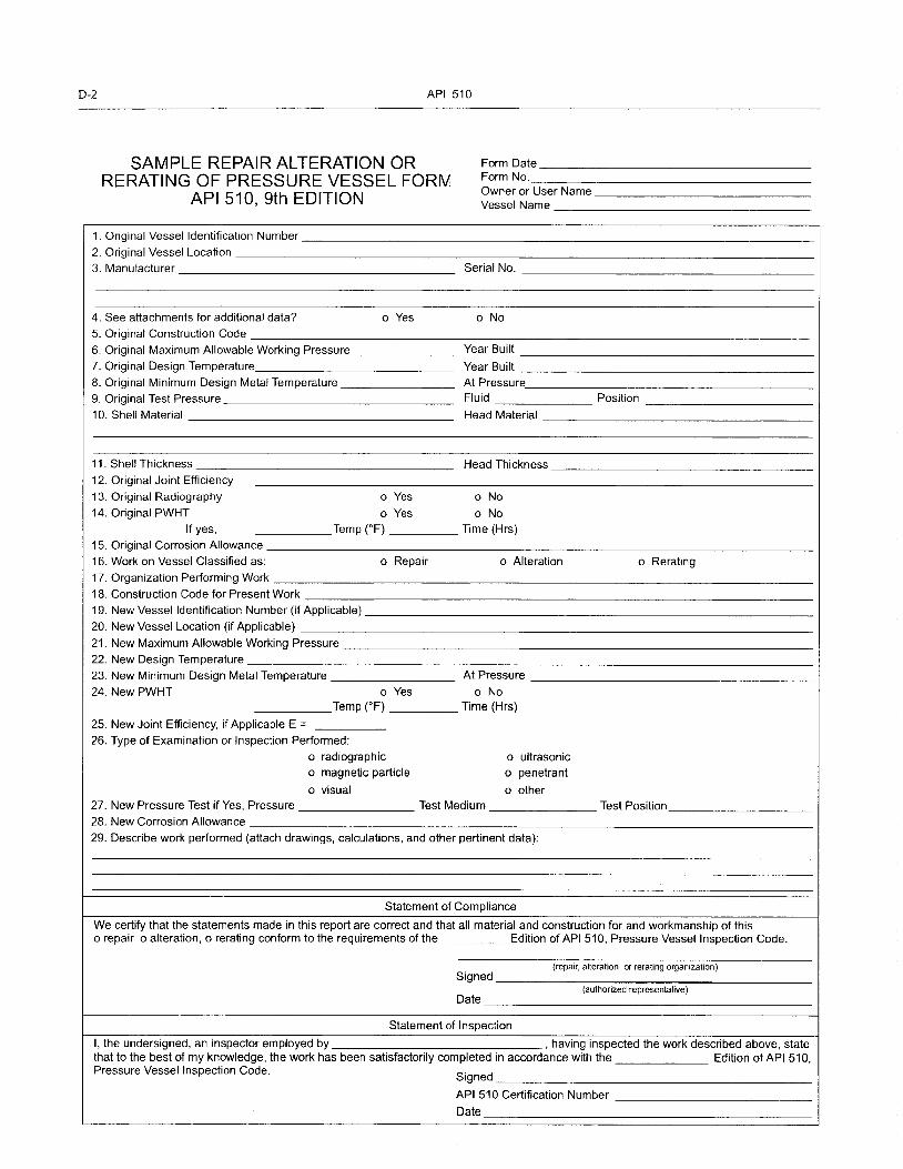
0-2 API 510
SAMPLE REPAIR ALTERATION OR RERATING OF PRESSURE VESSEL FORM
API 510, 9th EDITION
1. Original Vessel Identification Number
2. Original Vessel Location 3. Manufacturer
4. See attachments for additional data? o Yes 5. Original Construction Code
6. Original Maximum Allowable Working Pressure 7. Original Design Temperature 8. Original Minimum Design Metal Temperature 9. Original Test Pressure 10. Shell Material
11. Shell Thickness
12. Original Joint Efficiency 13. Original Radiography o Yes 14. Original PWHT 0 Yes
If yes, Temp (OF)
15. Original Corrosion Allowance 16. Work on Vessel Classified as: o Repair
17. Organization Performing Work
18. Construction Code for Present Work 19. New Vessel Identification Number (if Applicable)
20. New Vessel Location (if Applicable)
21. New Maximum Allowable Working Pressure 22. New Design Temperature 23. New Minimum Design Metal Temperature 24. NewPWHT 0 Yes
Temp rF)
25. New Joint Efficiency, if Applicable E =
26. Type of Examination or Inspection Performed: o radiographic o magnetic particle
o visual
Form Date __________________ _ Form No. ___________________ __ Owner or User Name ________________ _ Vessel Name _________________ _
Serial No.
o No
Year Built
Year Built At Pressure Fluid Position
Head Material
Head Thickness
o No
o No Time (Hrs)
o Alteration o Rerating
At Pressure
o No Time (Hrs)
o ultrasonic o penetrant
o other 27. New Pressure Test if Yes, Pressure Test Medium Test Position 28. New Corrosion Allowance 29. Describe work performed (attach drawings, calculations, and other pertinent data):
Statement of Compliance
We certify that the statements made in this report are correct and that all material and construction for and workmanship of this o repair 0 alteration, 0 rerating conform to the requirements of the Edition of API 510, Pressure Vessel Inspection Code.
Signed (repair, alteration, or rerating organization)
Date (authorized representative)
Statement of Inspection
I, the undersigned, an inspector employed by , having inspected the work described above, state that to the best of my knowledge, the work has been satisfactorily completed in accordance with the Edition of API 510, Pressure Vessel Inspection Code.
Signed
API 510 Certification Number
Date
APPENDIX E-TECHNICAL INQUIRIES
E.1 Introduction API will consider written requests for interpretations of API 510. API staff will make such interpretations in writing after consultation, if necessary, with the appropriate committee officers and the committee membership. The API committee responsible for maintaining API 510 meets regularly to consider written requests for interpretations and revisions and to develop new criteria as dictated by technological development. The committee's activities in this regard are limited strictly to interpretations of the standard or to the consideration of revisions to the present standard on the basis of new data or technology. As a matter of policy, API does not approve, certify, rate, or endorse any item, construction, proprietary device, or activity; thus, accordingly, inquiries requiring such consideration will be returned. Moreover, API does not act as a consultant on specific engineering problems or on the general understanding or application of the rules. If, based on the inquiry information submitted, it is the opinion of the committee that the inquirer should seek assistance, the inquiry will be returned with the recommendation that such assistance be obtained.
All inquiries that cannot be understood because they lack information will be returned.
E.2 Inquiry Format Inquiries shall be limited strictly to requests for interpretation of the standard or to the consideration of revisions to the standard on the basis of new data or technology. Inquiries shall be submitted in the following format:
a. Scope. The inquiry shall involve a single subject or closely related subjects. An inquiry letter concerning unrelated subjects will be returned. b. Background. The inquiry letter shall state the purpose of the inquiry, which shall be either to obtain an interpretation of the standard or to propose consideration of a revision to the standard. The letter shall provide concisely the information needed for complete understanding of the inquiry (with sketches, as necessary). This information shall include reference to the applicable edition, revision, paragraphs, figures, and tables. c. Inquiry. The inquiry shall be stated in a condensed and precise question format. Superfluous background information shall be omitted from the inquiry, and where appropriate, the inquiry shall be composed so that "yes" or "no" (perhaps with provisos) would be a suitable reply. This inquiry statement should be technically and editorially correct. The inquirer shall state what he believes the standard requires. If in his opinion a revision to the standard is needed, he shall provide recommended wording.
The inquiry should be typed; however, legible handwritten inquiries will be considered. The name and the mailing address of the inquirer must be included with the proposal. The proposal shall be submitted to the following address: director of the Standards Department, American Petroleum Institute, 1220 L Street, N.W., Washington, D.C. 20005-4070, [email protected].
E.3 Technical Inquiry Responses
Responses to previous technical inquiries can be found on the API website at http://committees.api.org/standards/techlindex.html.
E-1


Effective January 1, 2006. API Members receive a 30% discount where applicable.
American Petroleum Institute The member discount does not apply to purchases made for the purpose of resale or for incorporation into commercial products, training courses, workshops, or other commercial enterprises.
2006 Publications Order Form
Available through Global Engineering Documents:
Date:
Phone Orders: 1-800-854-7179 (Toll-free in the U.S. and Canada)
Fax Orders:
Online Orders:
303-397-7956 (Local and International)
303-397-2740 www.globaLihs.com
o API Member (Check if Yes)
Invoice To (0 Check here if sarne as "Ship To")
Narne:
Ship To (UPS will not deliver to a P.O. Box)
Name:
Title: Title:
Company: Company:
Depa rtrnent: Department:
Address: Address:
City: State/Province: City: State/Province:
Zip/Postal Code: Country: Zip/Postal Code: Country:
Telephone: Telephone:
Fax: Fax:
E-Mail: E-Mail:
Quantity Product Number Title 50* Unit Price Total
C57003 API 570, Piping Inspection Code: Inspection, Repair, Alteration, and Rerating of $98.00 In-service Piping Systems
C57101 RP 571, Damage Mechanisms Affecting Fixed Equipment in the Refining Industry $184.00
C57202 RP 572, Inspection of Pressure Vessels $90.00
C57402 RP 574, Inspection Practices for Piping System Componets $98.00
C57602 RP 576, Inspection of Pressure Relieving Devices $98.00
C57801 RP 578. Material Verification Program for New and Existing Alloy Piping Systems $98.00
C57901 RP 579, Fitness-far-Service $613.00
C65303 STD 653. Tank Inspection, Repair. Alteration, and Reconstruction $176.00
o Payment Enclosed o P.O. No. (Enclose Copy) Subtotal
o Charge My Global Account No. Applicable Sales Tax (see be/ow)
Rush Shipping Fee (see be/ow)
o VISA o MasterCard o American Express o Diners Club o Discover Shipping and Handling (see be/ow)
Credit Card No.: Total (in U.S. Dollars)
Pnnt Name (As It Appears on Card).
Expiration Date:
* To be placed on Standing Order for future editions of this publication, place a check mark in the SO column and sign here:
Signature: Pricing and availability subject to change without notice.
Mail Orders - Payment by check or money order in U.S. dollars is required except for established accounts. State and local taxes, $10 processing fee', and 5% shipping must be added. Send mail orders to: API Publications, Global Engineering Documents, 15 Inverness Way East, MIS C303B, Englewood, CO 80112-5776, USA. Purchase Orders - Purchase orders are accepted from established accounts. Invoice will include actual freight cost, a $10 processing fee', plus state and local taxes. Telephone Orders - If ordering by telephone, a $10 processing fee' and actual freight costs will be added to the order. Sales Tax - All U.S. purchases must include applicable state and local sales tax. Customers claiming tax-exempt status must provide Global with a copy of their exemption certificate. Shipping (U.S. Orders) - Orders shipped within the U.S. are sent via traceable means. Most orders are shipped the same day. Subscription updates are sent by First-Class Mail. Other options, including next-day service, air service, and fax transmission are available at additional cost. Call 1-800-854-7179 for more information. Shipping (International Orders) - Standard international shipping is by air express courier service. Subscription updates are sent by World Mail. Normal delivery is 3-4 days from shipping date. Rush Shipping Fee - Next Day Delivery orders charge is $20 in addition to the carrier charges. Next Day Delivery orders must be placed by 2:00 p.m. MST to ensure overnight delivery. Returns - All returns must be pre-approved by calling Global's Customer Service Department at 1-800-624-3974 for information and assistance. There may be a 15% restocking fee. Special order items. electronic documents. and age-dated materials are non-returnable. *Minimum Order - There is a $50 minimum for all orders containing hardcopy documents. The $50 minimum applies to the order subtotal including the $10 processing fee, excluding any applicable taxes and freight charges. If the total cost of the documents on the order plus the $10 processing fee is less than $50, the processing fee will be increased to bring the order amount up to the $50 minimum. This processing fee will be applied before any applicable deposit account. quantity or member discounts have been applied. There is no minimum for orders containing only electronically delivered documents.

• r I III
The American Petroleum Institute provides additional resources and programs to the oil and natural gas industry which are based on API@ Standards. For more information, contact:
• API Monogram@ Licensing Program
• American Petroleum Institute Quality Registrar (APIQR@)
• API Spec Q1@ Registration
• API Perforator Design Registration
• APllSOjTS 29001 Registration
• API Training Provider Certification Program
• Individual Certification Programs
• Engine Oil Licensing and Certification System (EOlCS)
• API PetroTEAMTM (Training, Education and Meetings)
Check out the API Publications, Programs, and Services Catalog online at www.api.org.
Phone: 202-962-4791 Fax: 202-682-8070
Phone: 202-962-4791 Fax: 202-682-8070
Phone: 202-962-4791 Fax: 202-682-8070
Phone: 202-962-4791 Fax: 202-682-8070
Phone: 202-962-4791 Fax: 202-682-8070
Phone: 202-682-8490 Fax: 202-682-8070
Phone: 202-682-8064 Fax: 202-682-8348
Phone: 202-682-8516 Fax: 202-962-4739
Phone: 202-682-8195 Fax: 202-682-8222
I American Petroleum Institute
Helping You Get The Job Done RightBl
Related Documents