API RP*LLPGT 92 m 0732290 0503459 bLL m Recommended Practice for Packaged Combustion Gas Turbines API RECOMMENDED PRACTICE 11 PGT (RP 11 PGT) FIRST EDITION, MAY 1, 1992 American Petroleum Institute 1220 L Street, Northwest Washington, DC 20005 ! P Copyright American Petroleum Institute Document provided by IHS Licensee=KVAERNER E & C (S) PTE LTD /5945820001, 10/28/2004 18:26:10 MDT Questions or comments about this message: please call the Document Policy Group at 303-397-2295. --``,,,,,,``,`,,`,````,`,,,,-`-`,,`,,`,`,,`---

API 11 RP PGT Packaged Combustion Gas Turbines
Oct 28, 2014
Welcome message from author
This document is posted to help you gain knowledge. Please leave a comment to let me know what you think about it! Share it to your friends and learn new things together.
Transcript

API RP*LLPGT 92 m 0732290 0503459 b L L m
Recommended Practice for Packaged Combustion Gas Turbines
API RECOMMENDED PRACTICE 11 PGT (RP 11 PGT) FIRST EDITION, MAY 1, 1992
American Petroleum Institute 1220 L Street, Northwest Washington, DC 20005 !P
Copyright American Petroleum Institute Reproduced by IHS under license with API
Document provided by IHS Licensee=KVAERNER E & C (S) PTE LTD /5945820001, 10/28/2004 18:26:10 MDT Questions or comments about this message: please callthe Document Policy Group at 303-397-2295.
--``,,,,,,``,`,,`,````,`,,,,-`-`,,`,,`,`,,`---

A P I RP*I,I,PGT 92 0732270 0503460 333
Issued by AMEMCANPETROLEXJMINS~
Production Department
FOR INFORMATION CONCERNING TECHNICAL CONTENT OF THIS PUBLICATION CONTACT THE API PRODUCTION DEPARTMENT,
SEE BACK COVER FOR INFORMATION CONCERNING HOW TO OBTAIN ADDITIONAL COPIES OF THIS PUBLICATION.
1201 MAIN STREET, SUITE 2535, DALLAS, TX 75202-39O4 - (214) 748-3841.
Users of this publication should become familiar with its scope and content, including any provisions it may have regarding marking of manufactured products. This document is intended to supplement rather
than replace individual engineering judgment.
OFFICIAL PUBLICATION
REG. U.S. PATENT OFFICE
Copyright Q 1992 American Petroleum Institute
Copyright American Petroleum Institute Reproduced by IHS under license with API
Document provided by IHS Licensee=KVAERNER E & C (S) PTE LTD /5945820001, 10/28/2004 18:26:10 MDT Questions or comments about this message: please callthe Document Policy Group at 303-397-2295.
--``,,,,,,``,`,,`,````,`,,,,-`-`,,`,,`,`,,`---
... . -~
A P I R P i l l P G T 92 0732290 0503463 27T = 2 American Petroleum Institute
CONTENTS Page POLICY .......................................................................................................................................... 5 FOREWORD ................................................................................................................................... 6 SECTION 1 - GENERAL
1.1 Scope .................................................................................................................................... 7 1.2 Alternative Designs .............................................................................................................. 7 1.3 Conflicting Requirements ..................................................................................................... 7
1.5 Referenced Publications ....................................................................................................... 8
2.1 Site Specific Requirements ................................................................................................... 11
2.1.2 Unit Responsibility., .................................................................................................. 11 2.1.3 Site Rating Condition ................................................................................................ 11
2.1.5 Transient Requirements ........................................................................................... 11
2.1.7 MaintenanceAnspection ............................................................................................ 11
2.1.9 Site Condition/Environment ...................................................................................... 11
2.1.11 Emission ................................................................................................................... 11
2.2 Package Design .................................................................................................................... 11 2.2.1 Packaged Equipment ................................................................................................ 11 2.2.2 Shipped Loose Equipment ......................................................................................... 12 2.2.3 Other Equipment ...................................................................................................... 12 2.2.4 Preliminary Review .................................................................................................. 12 2.2.5 Motors and Electrical Components ............................................................................ 12
2.2.7 Rating Condition ....................................................................................................... 12 2.2.8 Operating Criteria .................................................................................................... 12 2.2.9 Starting Requirements .............................................................................................. 12
2.2.11 Package Arrangement .............................................................................................. 12 2.2.12 Maintenance Requirements ...................................................................................... 12 2.2.13 Oil Reservoirs and Housings ..................................................................................... 12 2.2.14 Steam or Water Injection .......................................................................................... 13 2.2.15 Control Requirements ............................................................................................... 13 2.2.16 Special Tools and Fixtures ........................................................................................ 13
2.3 Gas Turbine Drive Train Mechanical Equipment Componen ts ............................................ 13 2.3.1 Gas Turbine Drivers ................................................................................................. 13 2.3.2 Couplings and Guards ............................................................................................... 13
2.3.4 Load Gears ................................................................................................................ 13
2.3.6 Vibration and Balance ............................................................................................... 14
2.4.1 General ..................................................................................................................... 15 2.4.2 Packager Responsibility ............................................................................................ 15 2.4.3 Critical Speeds .......................................................................................................... 15
1.4 DefinitionofTerms .............................................................................................................. 7
SECTION 2 - BASIC PACKAGE DESIGN
2.1.1 Service Life ............................................................................................................... 11
2.1.4 Starting Requirements .............................................................................................. 11
2.1.6 Instnunentation/Comcation .............................................................................. 11
2.1.8 Spare Pa& ............................................................................................................... 11
2.1.10 Sound Level .............................................................................................................. 11
2.1.12 Fuels ......................................................................................................................... 11
2.2.6 Operating SpeedRange ............................................................................................. 12
2.2.10 Temperaturdspeed Li mits ........................................................................................ 12
2.2.17 Compartment Enclosure(s) ....................................................................................... 13
2.3.3 Auxiliary Gears ......................................................................................................... 13
2.3.5 DrivenEquipment .................................................................................................... 13
2.4 Critical Lateral and Torsional Speeds - ConsiderationdResponsibilities ............................ 15
Copyright American Petroleum Institute Reproduced by IHS under license with API
Document provided by IHS Licensee=KVAERNER E & C (S) PTE LTD /5945820001, 10/28/2004 18:26:10 MDT Questions or comments about this message: please callthe Document Policy Group at 303-397-2295.
--``,,,,,,``,`,,`,````,`,,,,-`-`,,`,,`,`,,`---
A P I RPwLLPGT 92 0732290 0503462 Lob
.
a
. ....... RP 1lPGT Packaged Cornbustion-GasTurbines _. ~ 3 ~ .. .... ..... ._
TABLE OF CONTENTS (Continued) Page 2.5 Dynamics ............................................................................................................................. 16
2.5.1 General ....................................................................................................................... 16 2.5.2 Lateral Analysis ......................................................................................................... 17 2.5.3 Shop Verification of Unbalance Response Analysis ..................................................... 18 2.5.4 Torsional Analysis ...................................................................................................... 19
2.6 Materials of Package Construction ...................................................................................... 19 2.6.1 General ....................................................................................................................... 19 2.6.2 Welding ...................................................................................................................... 19 2.6.3 Piping and Tubing ...................................................................................................... 19 2.6.4 Structural ................................................................................................................... 20 2.6.5 Galvanized Steel ......................................................................................................... 20 2.6.6 Nonmetallic Materials ................................................................................................ 20 2.6.7 Bolting ........................................................................................................................ 20
2.7 Nameplate ........................................................................................................................... 20 SECTION 3 -ACCESSORY SYSTEMS 3.1 Starting Systems ................................................................................................................. 21 3.2 Mounting Systems ............................................................................................................... 21
3.2.1 General ....................................................................................................................... 21 3.2.2 Anchor Systems .......................................................................................................... 21 3.2.3 Baseplate Design ........................................................................................................ 21 3.2.4 Equipment Mounting ................................................................................................. 22
3.3 Enclosure and Fire Protection ............................................................................................. 22 3.3.1 General ....................................................................................................................... 22 3.3.2 Construction ............................................................................................................... 22 3.3.3 Fire Protection ............................................................................................................ 22 3.3.4 Ventilation and Purging ............................................................................................. 22
3.4 Air Inlet Systems ................................................................................................................. 23 3.4.1 General ....................................................................................................................... 23 3.4.2 Inlet Filters ................................................................................................................ 23 3.4.3 Inlet Silencers ............................................................................................................. 23 3.4.4 Inlet Ducting .............................................................................................................. 24 3.4.5 Evaporative Cooling System ....................................................................................... 24 3.4.6 Water Wash System ................................................................................................... 24 3.4.7 Anti-icing System ....................................................................................................... 25
3.5 Exhaust System ................................................................................................................... 25 3.6 Piping .................................................................................................................................. 25
3.6.1 General ....................................................................................................................... 25 3.6.2 Oil Piping ................................................................................................................... 27 3.6.3 Instrument Piping ...................................................................................................... 27 3.6.4 Water Injection Piping System ................................................................................... 28 3.6.5 Process piping ............................................................................................................ 28
3.7 Oil System ........................................................................................................................... 28 3.8 Fuel System ......................................................................................................................... 28
3.8.1 General ....................................................................................................................... 28 3.8.2 Gaseous Fuel .............................................................................................................. 29 3.8.3 LiquidFuel ................................................................................................................. 29 3.8.4 Dual Fuel Operation ................................................................................................... 29 3.8.5 WaterISteam Injection Operation ............................................................................... 29
3.9 Controls and Instrumentation ............................................................................................. 29 3.9.1 General ....................................................................................................................... 29 3.9.2 Starting Control ......................................................................................................... 30
Copyright American Petroleum Institute Reproduced by IHS under license with API
Document provided by IHS Licensee=KVAERNER E & C (S) PTE LTD /5945820001, 10/28/2004 18:26:10 MDT Questions or comments about this message: please callthe Document Policy Group at 303-397-2295.
--``,,,,,,``,`,,`,````,`,,,,-`-`,,`,,`,`,,`---
.
A P I R P * L l P G T 92 W 0732290 0503463 042 W
4 American Petroleum Institute
TABLE OF CONTENTS (Continued) Page 3.9.3 Instrument and Control Panel .................................................................................... 30 3.9.4 Instrumentation ......................................................................................................... 30
3.10 Electrical System ............................................................................................................... 31
4.1 General ................................................................................................................................ 32 4.2 Inspection ............................................................................................................................ 32
4.2.1 General ....................................................................................................................... 32 4.2.2 Material Inspection .................................................................................................... 32 4.2.3 Mechanical Inspection ................................................................................................ 33
4.3 Testing ................................................................................................................................. 33 4.3.1 General ....................................................................................................................... 33 4.3.2 HydrostaticTest ......................................................................................................... 33 4.3.3 Gas Generator Test .................................................................................................... 33 4.3.4 Complete Unit No-load Mechanical Running Test ...................................................... 35 4.3.5 OptionalTests ............................................................................................................ 36
4.4 Preparation for Shipment .................................................................................................... 36
5.1 Proposals ............................................................................................................................. 38 5.2 ContractData ...................................................................................................................... 38
5.2.1 General ....................................................................................................................... 38 5.2.2 Drawings .................................................................................................................... 39 5.2.3 Technical Data ........................................................................................................... 39 5.2.4 RecommendedSpare .................................................................................................. 39 5.2.5 Installation. Operation. and Maintenance Manuals ................................................... 39 5.2.6 Technical Data Manual .............................................................................................. 39
SECTION 4 - INSPECTION, TESTING. AND PREPARATION FOR SHIPMENT
SECTION 5 - PACKAGER'S DATA
APPENDMA-TYPICALDATASHEETS .................................................................................. 40 APPENDIX B - PACKAGER DRAWING AND DATA REQUIREMENTS ................................... 53 APPENDM C - PROCEDURE FOR DETERMINATION OF RESIDUAL UNBALANCE ........... 60 APPENDIX D - PURCHASER'S CHECKLIST ............................................................................. 63 APPENDIX E - INSPECTION AND TESTING OF LARGE ELECTRIC AC GENERATORS ...... 68 FIGURES
1 - Rotor Response Plot ............................................................................................................ 16 2 - Testing Logic Diagram ........................................................................................................ 34 C-1 - Sample Plot and Calculation of Residual Unbalance ....................................................... 61 E-1 - Shaft Displacement Limits Relative to Bearing Housing ................................................. 71
1-Minimum Requirements for Piping and Tubing Systems .................................................... 26 2 - Minimum Tubing Wall Thicknesses .................................................................................... 28 3 - Maximum Severity of Defects in Castings ........................................................................... 32 E.l- Generator Vibration Amplitudes ..................................................................................... 70
TABLES
Copyright American Petroleum Institute Reproduced by IHS under license with API
Document provided by IHS Licensee=KVAERNER E & C (S) PTE LTD /5945820001, 10/28/2004 18:26:10 MDT Questions or comments about this message: please callthe Document Policy Group at 303-397-2295.
--``,,,,,,``,`,,`,````,`,,,,-`-`,,`,,`,`,,`---
A P I RP*KLLPGT 92 0732290 0503464 Ti39
_ _ ~ .- -~ -. .-i -. _ s ~ -. - RP 11PGT Packaged Combustion Gas Turbines - ~ . _ _ _ ____ ~..____. ~-
5
POLICY API PUBLICATIONS NECESSARILY ADDRESS PROBLEMS OF A GENERAL NATURE. WITH RESPECT TO PARTICULAR CIRCUMSTANCES,
ULATIONS SHOULD BE REVIEWED.
API IS NOT UNDERTAKING TO MEET DUTIES
PLIERS TO WARN AND PROPERLY TRAIN AND
POSED, CONCERNING HEALTH AND SAFETY RISKS AXD PRECAUTIONS, NOR UNDERTAKING THEIR OBLIGATIONS UNDER LOCAL. STATE. OR
LOCAL, STATE AND FEDERAL LAWS AND REG-
OF EMPLOYERS, MANUFACTURERS OR SUP-
EQUIP THEIR EMPLOYEES, AND OTHER EX-
FEDERAL LAWS. NOTHING CONTAINED IN ANY API PUBLICA- TION IS TO BE CONSTRUED AS GRANTING ANY RIGHT, BY IMPLICATION OR OTHERWISE, FOR THE MANUFACTURE, SALE, OR USE OF ANY METHOD, APPARATUS, OR PRODUCT COVERED BY LETTERS PATENT. NEITHER SHOULD AhT-
THING CONTAINED IN THE PUBLICATION BE CONSTRUED AS INSURING ANYONE AGAINST LIABILITY FOR INFRINGEMENT OF LETTERS PATENT. GENERALLY. API STANDARDS ARE REVIEWED AND REVISED, REAFFIRMED, OR WITHDRAWN AT LEAST EVERY FIVE YEARS. SOMETIMES A ONE-TIME EXTENSION OF UP TO TWO YEARS WILL BE ADDED TO THIS REVIEW CYCLEYpeIS PUBLICATION WILL NO LONGER BE IN EFFECT FIVE YEARS AFTER ITS PUBLICATION DATE AS AN OPERATIVE API STANDARD-OR,-WIIERE AN EXTENSION HAS BEEN GRANTED, UPON REPUBLICATION. STATUS OF THE PUBLICATION CAN BE ASCERTAINED FROM THE APIAfi-HOR- OF API PUBLICATIONS AND MATERIALS IS
TERLY BY API. 1220 L ST., N.W., WASHINGTON, D.C. 20005.
ING DEPARTMENT (TEL. 214-748-3841). A CATALOG
PUBLISHED ANNUALLY AND UPDATED QUAR-
Copyright American Petroleum Institute Reproduced by IHS under license with API
Document provided by IHS Licensee=KVAERNER E & C (S) PTE LTD /5945820001, 10/28/2004 18:26:10 MDT Questions or comments about this message: please callthe Document Policy Group at 303-397-2295.
--``,,,,,,``,`,,`,````,`,,,,-`-`,,`,,`,`,,`---

A P I R P * I I P G T 92 m 0732290 0503465 915 m
6 American Petroleum Institute
FOREWORD (a) This publication is under the jurisdiction of the API Committee on Standardization of Production Equipment. (b) American Petroleum Institute (API) Recommended Practices are published to facilitate the broad availabil- ity of proven, sound engineering and operating prac- tices. These Recommended Practices are not intended to obviate the need for applying sound judgment as to when and where these Recommended Practices should be uti- lized. (c) The formulation and publication of API Recom- mended Practices is not intended to, in any way, inhibit anyone from using any other practices. (d) Any Recommended Practice may be used by anyone desiring to do so, and a diligent effort has been made by API to assure the accuracy and reliability of the data contained herein. However, the Institute makes no rep- resentation, warranty or guarantee in connection with the publication of any Recommended Practice and hereby expressly disclaims any liability or responsibility for loss or damage resulting from its use, for any violation of any federal, state or municipal regulation with which an API recommendation may conflict, or for the infringement of any patent resulting from the use of this publication. This recommended practice is based on the accumulated knowledge and experience of turbine manufacturers, turbine equipment packagers, and users. The objective is to provide a primary procurement document for the design, manufacture, and testing of a complete gas tur- bine package including the driven equipment. This pack- aged equipment is intended for use in oil and gas produc- tion service.
Note:
This is the first edition of this specification and was approved by Letter Ballet as Practices taken at the 1991 Standardization Conference Circ PS 1952.
Historically, API Standard 616 "Gas Turbines for Re- finery Service" has been the industry standard for gas turbine equipment procurement, API RP 11 PGT "Rec- ommended Practice for Packaged Combustion Gas Tur- bines" allows the purchaser the option of requiring com- pliance with Section 2 of API 616, the turbine manufacturer's standard, or the purchaser's own speci- fication. The purchaser must decide which option best suits the application.
1) API Standard 616 generally addresses industrial, heavy frame type gas turbines. It considers aircraft- derivative designs but not extensively. API Standard 616 was written specifically for refinery services. It should not be used with this packaging specification in its entirety.
2) Specifying a turbine manufacturer's standard de- sign recognizes that most gas turbines are highly standardized machines. This specification provides general requirements and limitations in applying these standard turbine designs.
3) Purchasers may prefer to prepare their own speci- fication to supplement this document.
This packaging recommended practice also accommo- dates options for driven equipment. The purchaser must evaluate the component specifications available and de- termine which is most appropriate for the service. This recommended practice is not intended to inhibit techni- cal innovations, energy conservation, or cost reductions.
or any part of the material published herein should be Requests for permission to reproduce or translate all
addressed to the Director, American Petroleum Institute, Production Department, 1201 Main Street, Suite 2535, Dallas, Texas 75202-3904.
Copyright American Petroleum Institute Reproduced by IHS under license with API
Document provided by IHS Licensee=KVAERNER E & C (S) PTE LTD /5945820001, 10/28/2004 18:26:10 MDT Questions or comments about this message: please callthe Document Policy Group at 303-397-2295.
--``,,,,,,``,`,,`,````,`,,,,-`-`,,`,,`,`,,`---
RP 1lPGT: P a c s C o m b u s t i o n GasTurbines ~ ___ 7 .- I_.-_ . ~ .~ ___ ~ . ~. ~____
~~ ~- -.
SECTION 1 GENERAL
1.1 Scope. This recommended practice is intended to cover the minimum requirements for a complete self- sufficient packaged combustion gas turbine prime mover with or without driven equipment for onshoreloffshore oil and gas production services. The package shall be factory assembled to the maximum extent possible as limited by the mode of transportation. All auxiliary equipment required for operating, starting, controlling, and protecting the turbineldriven equipment is included directly or by reference in this recommended practice. Specifically intended to be covered are gas turbine pack- ages capable of continuous service firing gas fuel, liquid fuel, or both. NOTE: A bullet ( 0 ) in the margin indicates that a deci- sion by the purchaser is required. These decisions should be indicated directly on the data sheets when provisions are made for them; otherwise, they should be stated in the quotation request or in the order. 1.2 Alternative Designs. The packager may offer al- ternative designs [5.1.11. Equivalent metric dimensions, fasteners, and flanges may be substituted as mutually agreed upon by the purchaser and the packager. 1.3 Conflicting Requirements. In case of conflict be- tween this recommended practice and the inquiry or order, the information included in the order shall gov- ern. The packager and purchaser should jointly deter- mine and quickly resolve any conflicts before placement of the order. 1.4 Definition of Terms. The terms used in this rec- ommended practice are defined as follows: 1.4.1 Alarm point is a preset value of a parameter at which an alarm is actuated to warn of a condition requiring corrective action. 1.4.2 Axially split refers to casing joints that are parallel to the shaft centerline. 1.4.3 Critical speed corresponds to resonant frequen- cies of the system and of the forcing phenomena. If the frequency of any harmonic component of a periodic forcing phenomenon is equal to, or approximates the frequency of any mode of rotor vibration, a condition of resonance may exist; if resonance exists at a finite speed, that speed is called a critical speed. 1.4.4 Use of the word Design in any terms such as design power, design pressure, design temperature, or design speed should be avoided in the purchaser's specifications. This terminology should be used only by the equipment designer and manufacturer. 1.4.5 A Filter Stage is a section of a filter system which is designed to remove specific site contaminants at a prescribed efficiency and pressure drop. A stage may be a specific media, an inertial separator, a mist eliminator, or a self-cleaning section. Multistage fil- ters are combinations of the various filter stages. 1.4.6 Gas generators are devices in which only that energy required to drive the compressor stages and auxiliaries is extracted from the discharging gas by its turbine stages. 1.4.7 Heat rate is the gas turbine's energy consump- tion per unit of output work. Heat rate is expressed in British Thermal Units (BTU) per horsepower-hour at
the output shaft for mechanical drives or in BTU per kilowatt-hour at the generator terminals for electric generator sets. Both are based on the lower heating value of the fuel.
1.4.8 Inlet cubic feet per minute (ICFM) refers to the flow rate determined at the conditions of pressure, temperature, compressibility, and gas composition, in- cluding moisture at the compressor inlet flange. Ac- tual cubic feet per minute (ACFM) may be used to refer to flow at a number of locations and should, therefore, not be used interchangeably with inlet cubic feet per minute.
1.4.9 Local means mounted on, attached to, or adja- cent to the package or equipment skids.
1.4.10 Maximum allowable speed (in revolutions per minute) is the highest speed at which the manufacturer's design will permit continuous opera- tion.
1.4.11 Maximum allowable temperature is the maximum continuous temperature for which the manu- facturer has designed the equipment (or any part to which the term is referred) when handling the speci- fied fluid at the specified pressure.
1.4.12 Maximum allowable working pressure is the maximum continuous pressure for which the manu- facturer has designed the equipment (or any part to which the term is referred) when handling the speci- fied fluid at the specified temperature [Appendix A].
1.4.13 Maximum continuous speed (in revolutions per minute) is the speed at least equal to 105 percent of the highest speed required by any of the specified operating conditions.
1.4.14 Minimum allowable speed (in revolutions per minute) is the lowest speed at which the manu- facturer's design will permit continuous operation.
1.4.15 Normally open and normally closed refer to "on-the-shelf' positions and designate the de-energized positions of devices such as automatically controlled electric switches and valves. It is emphasized that the position of such a device during operation of the equip- ment is not necessarily the same as the device's "on- the-shelf' position.
1.4.16 Normal operating point is the point at which usual operation is expected and optimum efficiency is desired. This point is usually the point at which the packager certifies that performance is within the tol- erances stated in this practice. "his includes power, speed, and heat rate at specified site conditions and fuel composition.
1.4.17 The packager is the vendor having responsi- bility for coordinating the technical aspects of the equipment, and all auxiliary systems included in the scope of the order L2.2.1, 2.2.2, 2.2.31. Responsibility for such factors as the power requirements, speed, rotation, general arrangement, couplings, dynamics, noise, lubrication, sealing system, material test re- ports, instrumentation, piping, and testing of compo- nents is included.
Copyright American Petroleum Institute Reproduced by IHS under license with API
Document provided by IHS Licensee=KVAERNER E & C (S) PTE LTD /5945820001, 10/28/2004 18:26:10 MDT Questions or comments about this message: please callthe Document Policy Group at 303-397-2295.
--``,,,,,,``,`,,`,````,`,,,,-`-`,,`,,`,`,,`---
API RPaLLPGT 92 07321fqO 0503Yb-7 79e -... . .
8 . American Petroleum Institute
1.4.18 Panel is an enclosure used to mount, display, and protect gages, switches, and other instruments. 1.4.19 Potential maximum power is the expected power capability when the gas turbine is operated at maximum allowable firing temperature, rated speed, or other limiting conditions as defined by the manufac- turer and within the range of specified site values. 1.4.20 Power turbine is a mechanical prime mover specifically designed for recovery of energy from hot gases produced by the gas generator. 1.4.21 The pressure casing is the composite of all stationary pressure containing parts of the unit, in- cluding all nozzles and other attached parts. 1.4.22 Radially split refers to casing joints that are transverse to the shaft centerline. 1.4.23 Rated cycle temperature at IS0 conditions is the vendor's stated (calculated) turbine inlet total temperature, immediately upstream of the first stage turbine rotor blades for continuous service at IS0 rated power output. 1.4.24 Rated firing temperature at IS0 conditions is the vendor's stated (calculated) turbine inlet tem- perature, immediately upstream of the first-stage tur- bine nozzles, for continuous service at IS0 rated power output. 1.4.25 Rated power at IS0 conditions is the con- tinuous power developed by the gas turbine when it is operated at rated firing temperature and speed under the following standard operating conditions (IS0 2314).
Inlet temperature 59 F (15 C) Inlet (total) pressure 14.696 psia
(1.0133 bar) Inlet Relative Humidity 60% Exhaust pressure 14.696 psia
(1.0133 bar) This power and speed is measured at the output shaft of the gas turbine ahead of any separate gears .or driven equipment except in the case of electric genera- tors where power output is measured at the generator terminals. The inlet conditions shall be measured at the gas generator inlet flange and exhaust conditions at the exhaust flange. These measuring points shall be utilized for all power and gas flow measurements. The IS0 rating provides only general sizing information and should not be confused with the site rated power. 1.4.26 Rated speed (in revolutions per minute) is the speed of the gas turbine output shaft at which site rated power is developed. 1.4.27 Remote means located away from the package or equipment skids, typically in a control room or data transmission facility.
1.4.28 Site rated conditions are the specified values of the inlet air temperature, inlet air pressure, and exhaust gas pressure at which site rated power is required. Inlet and exhaust ducting and other facili- ties, barometric variations, and ambient temperature ranges shall be considered when specifying the site rated conditions.
1.4.29 Site rated cycle temperature is the turbine inlet total temperature immediately upstream of the first stage turbine rotor blades, required t o meet site rated power. 1.4.30 Site rated firing temperature is the turbine inlet temperature, immediately upstream of the first stage turbine nozzles, required to meet site rated power. 1.4.31 Site rated power is the power developed by the gas turbine at the output shaft when it is operated at site rated firing temperature, rated speed, and rated site conditions, rated fuel composition, and with or without steam or water injection. (External auxiliaries are not included in parasitic losses.) 1.4.32 Shutdown point is a preset value of a param- eter requiring automatic or manual shutdown of the system. 1.4.33 Standard cubic feet per minute (SCFM) refers to capacity at a pressure of 14.7 pounds per square inch absolute (1.01 bar) and a temperature of 60°F (15.56"C). 1.4.34 Standby service refers to a normally idle or idling piece of equipment that is capable of immediate automatic or manual start-up and continuous opera- tion. 1.4.35 Thermal efficiency (9) is the ratio of the energy output at the power turbine shaft to the energy input (based on lower heating value of the fuel) ex- pressed in the same units. (External auxiliaries are not included in parasitic losses.) q = Outuut BHP X 2545 (Mechanical Drive)
Input BTU/HR (LHV)
q = gutput KW X 3413 (Generator Drive) Input BTU/HR (LHV)
1.4.36 Trip speed (in revolutions per minute) is the speed at which the independent emergency overspeed device operates to shut down the gas turbine.
1.5 Referenced Publications. 1.5.1 The purchaser and the packager shall mutually determine the measures that must be taken to comply with any federal, state, or local codes, regulations, ordinances, or rules that are applicable to the equip- ment (O.S.H.A., UBC, etc.). Purchaser will be respon- sible for providing applicable state and local codes, regulations, ordinances, and rules. 1.5.2 The current editions of the following standards, codes, and specifications shall, to the extent specified herein, form a part of this recommended practice. The applicability of changes in standards, codes, and speci- fications that occur after the inquiry shall be mutually agreed upon by the purchaser and the packager: AGMA'
Std 420 Practice for Helical and Herringbone Gear
Std 421 Practice for High Speed Helical and Her- Speed Reducers and Increasers
ringbone Gear Units AISC2 - Manual of Steel Construction AIS13 - Standard Type 300 Stainless Steel
- Standard Type 1020 Plain Carbon Steel
Copyright American Petroleum Institute Reproduced by IHS under license with API
Document provided by IHS Licensee=KVAERNER E & C (S) PTE LTD /5945820001, 10/28/2004 18:26:10 MDT Questions or comments about this message: please callthe Document Policy Group at 303-397-2295.
--``,,,,,,``,`,,`,````,`,,,,-`-`,,`,,`,`,,`---
A P I RP*I,LPGT 92 0732290 0503468 624 W
~= ~ . RP 11PGT Packaged Combustion Gas Turbines 9 _ _ . _ _ .
ANSI' B16.11 Forged Steel Fittings, Socket-Welding and
Threaded B16.5 Steel Pipe Flanges and Flanged Valves and
Fittings B31.3 Chemical Plant and Petroleum Refinery Pip-
ing C50.10 General Requirements for Synchronous Ma-
chines C50.12 Requirements for Salient-Pole
Synchronous Generators C50.13 Requirements for Cylindrical-Rotor
Synchronous Generators C50.14 Requirements for Combustion Gas Turbine
Driven Cylindrical Rotor Synchronous Gen- erators
S5.1 Test Code for the Measurement of Sound from Pneumatic Equipment
Y14.2M Line Conventions and Lettering API6
RP-541 Form Wound Squirrel-Cage Induction Motors, 250HP and Larger
RP-546 Form Wound Brushless Synchronous Motors - 500 hp and larger
RP-550 Manual on Installation of Refinery Instru- ments and Control Systems
Std 610 Centrifugal Pumps for General Refinery Ser- vices
Std 611 General Purpose Steam Turbines for Refin- ery Services
Std 613 Special Purpose Gear Units for Refinery Services
Std 614 Lubrication, Shaft-Sealing, and Control Oil Systems for Special Purpose Applications
Std 616 Gas Turbines for Refinery Services Std 617 Centrifugal Compressors for General Re-
Std 618 Reciprocating Compressors for General Re-
Std 660 Shell and Tube Heat Exchangers for Gen-
Std 661 Air Cooled Heat Exchangers for General
Std 670 Vibration, Axial-Position, and Bearing-Tem-
Std 671 Special Purpose Couplings for Refinery
SM 678 Accelerometer-Based Vibration Monitoring
finery Services
finery Services
eral Refinery Services
Refinery Services
perature Monitoring Systems
Services
System
Boiler and Pressure Vessel Code: ASME6
Section V, Nondestructive Examinations Section VIII, Unfired Pressure Vessels Section E, Welding and Brazing Qualifica- tions
ASTM' A36 A53
A105
A106
A120
A123
A153
A193
A194
A197 A202
A269
A307
A312
A338
A358
A500
A515
A524
A525
B1.20.1, General Purpose (inch) Pipe Threads B31.3, Chemical Plant and Petroleum Re- finery Piping
PTC-1, General Instructions. PTC-22, Gas Turbine Power Plants.
Power Test Code:
Structural Steel Zinc-Coated Welded and Seamless Black and Hot-Dipped Steel Pipe Carbon Steel Forgings for Piping Compo- nente Seamless Carbon Steel Pipe for High-Tem- perature Service Black and Hot-Dipped Zinc-Coated (Galva- nized) Welded and Seamless Steel Pipe for Ordinary Use Zinc (Hot Galvanized) Coatings on Products Fabricated from Rolled, Pressed, and Forged Steel Shapes, Plated. Bars, and Strip Zinc Coating (Hot Dipped) on Iron and Steel Hardware Alloy Steel and Stainless Steel Bolting Ma- terials for High Temperature Carbon and Alloy Steel Nuts for Bolts for High Pressure and High Temperature Serv- ice Cupola Malleable Iron Specification for Pressure Vessel Plates, Alloy Steel, Chromium-Manganese-Silicon Seamless and Welded Austenitic Stainless Steel Tubing for General Service Carbon Steel Externally Threaded Standard Fasteners Seamless and Welded Austenitic Stainless Steel Pipe Malleable Iron Flanges, Pipe Fittings, and Valve Parta for Railroad, Marine, and other Heavy Duty Service at Temperatures up to 650F (345C) Electric Fusion Welded Austenitic Cr-Ni Alloy Steels Pipes for High Temperature Service Cold Formed Welded and Seamless Carbon Steel Structural Tubing on Rounds and Shapes Pressure Vessel Plates, Carbon Steel, for Intermediate and Higher Temperature Serv- ice Seamless Carbon Steel Pipe for Atmospheric and Lower Temperatures General Requirements for Steel Sheet, Zinc Coated (Galvanized) by the Hot Dip Process
Copyright American Petroleum Institute Reproduced by IHS under license with API
Document provided by IHS Licensee=KVAERNER E & C (S) PTE LTD /5945820001, 10/28/2004 18:26:10 MDT Questions or comments about this message: please callthe Document Policy Group at 303-397-2295.
--``,,,,,,``,`,,`,````,`,,,,-`-`,,`,,`,`,,`---

A P I RP*LLPGT 92 E 0732290 0503469 560
10 American Petroleum Institute
A569
A591
A606
A662
E94 E125
E 142
E709 AWS8
D1.l IEEEg
45
115 522
IS010
Steel, Carbon (0.15 max), Hot Rolled Sheet and Strip, Commercial Quality Steel Sheet, Cold Rolled, Electrolytic Zinc Coated Steel Sheet and Strip, Hot Rolled and Cold Rolled, High Strength, Low Alloy, with Im- proved Atmospheric, Corrosion Resistance Specification for Pressure Vessel Plates, Car- bon, Manganese for Moderate and Lower Temperature Service. Guides for Radiographic Testing Reference Photographs for Magnetic Par- ticle Indications on Ferrous Castings Method for Controlling Quality of Radio- graphic Testing Practice for Magnetic Particle Examination
Structural Welding Code - Steel
Recommended Practice for Electrical Instal- lation on Shipboards Test Procedures for Synchronous Machines Guide for Testing Turn-to-Turn Insulation on Form-Wound Stator Coils for AC Rotat- ing Electric Machines, 1977 Edition (Reaf- firmed 1981)
ISO-2314 - Gas Turbines - Acceptance Tests 150-3448 - Standard Industrial Liquid Lubricants - IS0 Viscosity Classification
MIL" Mil-E-5007 Engines, Aircraft, Turbojet, and Tur-
Mil-STD-1534 Engines, Aircraft, Gas Turbines bofan, General Specifications for
Technical Design Requirements NACE12
MR-01
N E M A 1 3
MG1-20 MG1-21
MG1-22
SM-23
NFPA" 37
70
Sulfide Stress Corrosion Cracking Resis- tant Metallic Material for Oilfield Equip- ment
Motors and Generators (Induction Motors) Motors and Generators (Synchronous Mo- tors) Motors and Generators (Synchronous Gen- erators) Steam Turbines for Mechanical Drive Serv- ices
Stationam Combustion Engines and Gas Turbines - National Electrical Code 500 Laboratorv Classified Locations
-
501 Class I Lo-cations 502 Class I1 Locations
72E Automatic Fire Detectors OSHA16
Code of Federal Regulations (CFR) 29 CFR 1910 - Occupational Safety and Health Standards
SAE'G TEMA17 Standards, Codes, and Specification
UBC18 Uniform Building Code
Reference standards may be obtained from the follow- ing organizations. 'American Gear Manufacturer's Association, 1901 Fort Myer Dr., Arlington, VA 22209
%merican Institute of Steel Construction, Inc. 400 North Michigan Avenue, Chicago, IL 60611
3American Iron and Steel Institute, 1000 16th Street, N.W., Washington, DC 20036
4American National Standards Institute, 1430 Broad- way, New York, NY 10018
SAmerican Petroleum Institute, 1220 L Street North West, Washington, D.C. 20005
6American Society of Mechanical Engineers, 345 East 47th Street, New York, NY 10017
'American Society for Testing and Materials, 1916 Race Street, Philadelphia, PA 19103
8American Welding Society, 550 NW LeJeune Rd., Miami, FL 33135
sInstitute of Electrical and Electronic Engineers, 345 East 47th Street, New York, NY 10017-2394
'OInternational Organization for Standardization. IS0 publications are available from ANSI (4)
"Department of Defense - obtain from: Commanding Officer, Naval Publications Forms Center, A?TN: NPFC 105, 5801 Tabor Ave., Philadelphia, PA 19120
I2National Association of Corrosion Engineers, P.O. Box 218340, Houston, TX 77218
I3National Electrical Manufacturer's Association, 2101L Street, N W , Washington, DC 20037
"National Fire Protection Association, Batterymarch Park, Quincy, MA 02269
160ccupational Safety and Health Administration, U.S. Department of Labor. The Code of Federal Regula- tions is available from the U.S. Government Printing Office, Washington, DC 20402
'%ociety of Automotive Engineers, Inc., Aerospace Materials Division, 400 Commonwealth Drive, Warrendale, PA 15096
I7Tubular Exchanger Manufacturer's Association, 25 North Broadway, Tenytown, NY 10591
'*International Conference ofBuilding Officials (UBC), 5360 South Workman Mill Road, Whitter, CA 90601.
Copyright American Petroleum Institute Reproduced by IHS under license with API
Document provided by IHS Licensee=KVAERNER E & C (S) PTE LTD /5945820001, 10/28/2004 18:26:10 MDT Questions or comments about this message: please callthe Document Policy Group at 303-397-2295.
--``,,,,,,``,`,,`,````,`,,,,-`-`,,`,,`,`,,`---

A P I RP*:LLPGT 92 m 0732290 0503470 282 m
. =~ ~ . ~
- . . - _ . - RP 1lPGT PackagedCombustion Gas- Turbines ~. -. 11 ~. . ~ -~
SECTION 2 BASIC PACKAGE DESIGN
2.1 Site Specific Requirements. 2.1.1 Service Life. The complete package covered by this recommended practice shall be designed and con- structed for a minimum service life of 20 years and minimum uninterrupted continuous service interval of 3 years. The hot gas path inspection interval shall be a minimum of 8000 hours. It is recognized that these are design criteria. It is recognized that applications with marginal fuels and/or water or steam injection may require a more frequent inspection interval. It is the purchaser’s responsibility to provide the packager pertinent site information. It is the packager’s respon- sibility to identify in his proposal any special equip- ment and maintenance procedures necessary to achieve the aforesaid life and service intervals. 2.1.2 Unit Responsibility. The packager shall be responsible for complete train performance and the mechanical integrity of the entire package to meet specified performance. 2.1.3 Site Rating Condition. The purchaser will specify the package site specific operating point(s) on the data sheets [Appendix AI. Unless otherwise speci- fied, the gas turbine shall be designed to provide site rated power with no negative tolerance at the heat rate quoted. 2.1.4 Starting Requirements. The purchaser will define any operating requirements which impact start cycle sequence or duration r2.2.91. 2.1.5 Transient Requirements. Operational stabil- ity under load transients shall meet the requirement as specified by the purchaser. These requirements should be clearly defined by a relationship of load, speed, and time parameters. 2.1.6 InstrumentatiodCommunication. Minimum controls requirements are defined by 2.2.15. The pur- chaser will specify any additional requirements for instrumentation, data acquisition, data transmission, and system interface with total facility. 2.1.7 Maintenance/Inspection. Recommended in- spections, normal maintenance, and major overhaul intervals shall be stated in the packager’s proposal. The package shall be designed for ease in servicing and to provide adequate clearances necessary to perform all normal maintenance, and changeout of components on the package. Special tools and procedures shall be stated in the packager’s proposal. All tool lists, parts list, and maintenance procedures shall be included in the packager’s maintenance manual. 2.1.8 Spare Parts. 2.1.8.1 The packager shall consider the specific site conditions and include in his proposal a list of spares needed to complete package commissioning and field acceptance of initial operations. A second list of spares for three years operation shall also be included. 2.1.8.2 Spare parts for the package components shall be identical to originally installed parts.
2.1.9 Site ConditiodEnvironment. 2.1.9.1 The purchaser will furnish accurate site con- ditions to the packager that include but are not
limited to: location, climatic conditions (tempera- ture, humidity, wind, barometer, precipitation), air- borne atmospheric conditions (any unusual dust or corrosive environment, airborne pollutants, agricul- tural chemicals, etc.), site elevation, geological and seismic conditions. 2.1.9.2 The purchaser will advise the packager of the area classification(s) requirements.
B 2.1.9.3 The purchaser will specify whether the in- stallation is indoors (heated or unheated) or outdoors (with or without a roof) in which the equipment must operate.
B 2.1.9.4 Purchaser will state the degree of operator attendance. 2.1.9.5 The package and auxiliaries shall be suitable for operation under the specified conditions. For the purchaser’s guidance, the packager shall define in the proposal any special protection that the pur- chaser is required to supply.
B 2.1.10 Sound Level. Control of the sound pressure level (SPL) of all equipment furnished shall be a joint effort of the purchaser and the packager. The equip- ment furnished by the packager shall conform to the maximum allowable sound pressure level specified by the purchaser. 2.1.11 Emission. Control of exhaust emission levels of the package shall be a joint effort of the purchaser and the packager. The purchaser will specify the maxi- mum allowable emission levels at the package bound- aries. The packager shall state in his proposal ex- pected emission levels consistent with purchaser’s specified fuel properties and site operating conditions. The packager shall supply the turbine combustion emission suppression system to meet the specified levels of NOx, CO, and unburned hydrocarbons in the turbine’s exhaust gas.
@ 2.1.12 Fuels. The fuel system shall be operable with the normal fuel or any alternate or starting fuel speci- fied. Purchaser will provide the composition, range of heating values, temperatures, dew point temperature, pressure, contaminants, and other properties of the fuel supply. The packager shall advise the purchaser of the effects of the fuel(s) on turbine package operation and equipment life. When specified, the packager shall provide any fuel treatment equipment required [3.8].
2.2 Package Design. 2.2.1 Packaged Equipment. The packager shall pro- vide, as a minimum, the equipment listed below (re- ferred to herein as a “package”) packaged to meet the specified operating conditions. This equipment shall be assembled (packaged) to the maximum extent pos- sible. a. Baseplate(s1. b. Combustion gas generator. c. Controls and instrumentation. d. Couplings and guards. e. Exhaust collector. f. Fuel system(s1.
Copyright American Petroleum Institute Reproduced by IHS under license with API
Document provided by IHS Licensee=KVAERNER E & C (S) PTE LTD /5945820001, 10/28/2004 18:26:10 MDT Questions or comments about this message: please callthe Document Policy Group at 303-397-2295.
--``,,,,,,``,`,,`,````,`,,,,-`-`,,`,,`,`,,`---

12 American Petroleum Institute - g. Lube oil system(s). h. Power turbine (if separate from gas generator). i. Starting system. j, Gas Turbine washing or cleaning system. k. Vibration monitoring system. 2,2.2 Shipped Loose Equipment. The packager shall provide the accessory equipment listed below to meet the specified operating conditions. This equipment shall be either packaged or shipped loose. a. Control panel. b. Inlet ducting. c. Inlet filtration system. d. Inlet silencer. 2.2.3 Other Equipment. Any other equipment re- quired will be specified by the purchaser and shall be included in the packager’s proposal. Such equipment may include: a. Combustion emission control system. b. Driven equipment in accordance with applicable
specifications. c. Enclosure(s) for acoustical, weather, and/or fire
protection. d. Exhaust system (including expansion joints, silenc-
ers, structures). e. Fuel conditioning. f. Inlet evaporative air cooler. g. Inlet anti-icing system. h. Lifting equipment for maintenance. i. Lifting equipment for shipping and handling. j. Motor control center. k. Recuperator or regenerator for turbine performance
1. Starting system auxiliaries. m. Steam or water injection fluid conditioning system. n. Turbine load train condition monitoring equipment. 0. Uninterrupted power supply for controls, instru-
mentation, and operation. p. Waste heat recovery systems. 2.2.4 Preliminary Review. Many factors (such as piping and ducting loads, alignment at operating con- ditions, supporting structure, and assembly at the site) may adversely affect site performance. To minimize the influence of these factors, the packager shall re- view and comment on the purchaser’s piping, ducting, and foundation drawings. 2.2.5 Motors and Electrical Components. Motors, electrical components, and electrical installations shall be suitable for the area classification(s) (class, group, and division) specified by the purchaser on the data sheets and shall meet the requirements of NFPA 70, Articles 500 and 501, as well as local, state, and federal codes specified and furnished by the purchaser.
0 2.2.6 Operating Speed Range. The output shaft operating speed range of gas-turbine units for me-
enhancement.
chanical drive applications shall be suitable to meet all operating conditions specified by the purchaser on the data sheets. Where only one operating condition is specified for an application, the minimum speed range for single shaft machines shall be 25 percent (from 80 to 105 percent of rated speed) and the minimum speed range for two or more shaft machines shall be 55 percent (from 50 to 105 percent of rated speed). The turbine shall have satisfactory mechanical performance at all operating conditions specified on the data sheets and within the range among those conditions. The unit shall be capable of operation, without damage, to the trip speed setting at all operating conditions. 2.2.7 Rating Condition. The gas turbine package shall be mechanically designed and satisfactory for continuous service at potential maximum power l1.4.191. 2.2.8 Operating Criteria. 2.2.8.1 The package shall operate on the test stand and on its permanent foundation within the specified acceptance criteria r4.31. After installation, the ac- ceptance of mechanical and operating performance of the package shall be the joint responsibility of the purchaser and the packager. 2.2.8.2 The purchaser will specify the available util- ity supplies on the data sheets; the packager shall provide the required utility loads on the data sheets (Appendix A).
2.2.9 Starting Requirements. The package design shall permit immediate starting from any nonrotating condition. Any restrictions shall be defined in the pro- posal. 2.2.10 TemperatureBpeed Limits. Equipment shall be designed to run without damage at any speed up to the highest trip speed in combination with any of the packager’s allowable temperatures. 2.2.11 Package Arrangement. The arrangement of the package, including piping, coolers, pumps, and controls shall provide adequate clearance areas and safe access for operation and maintenance. 2.2.12 Maintenance Requirements. 2.2.12.1 All major equipment shall be designed to permit rapid and economical maintenance. Parts such as casing components and bearing housings shall be designed (shouldered or cylindrically doweled) and manufactured to ensure accurate alignment during reassembly. Stationary vanes, nozzles, seals, bear- ings, diaphragms, gas turbine modules, and the ro- tating elements shall be replaceable at site. The packager’s proposal shall describe the special tooling needed for the above purposes. If the equipment designs do not permit such replacement, the pack- ager shall state in his proposal the procedures re- quired for such repairs. 2.2.12.2 All equipment shall be suitable for periods of idleness up to 3 weeks, under specified site condi- tions, without requiring any special maintenance pro- cedures.
2.2.13 Oil Reservoirs and Housings. Oil reservoirs and housings that enclose moving lubricated parts (such as bearings, shaft seals, highly polished parts, instruments, and control elements) shall be designed to minimize contamination by moisture, dust, and other foreign matter during periods of operation and idle- ness.
Copyright American Petroleum Institute Reproduced by IHS under license with API
Document provided by IHS Licensee=KVAERNER E & C (S) PTE LTD /5945820001, 10/28/2004 18:26:10 MDT Questions or comments about this message: please callthe Document Policy Group at 303-397-2295.
--``,,,,,,``,`,,`,````,`,,,,-`-`,,`,,`,`,,`---

A P I R P * l l P G T 92 M 0732290 0503472 055 W ~~
~ .___ . . ~ _ _ - --I
R P 11PGT Packaged Co_m_bustion Gas Turbines -.
13
2.2.14 Steam or Water Injection. When specified, the gas turbine shall be designed to permit steam or water injection for either increasing the power capabil- ity of the unit or for emission control. The packager shall specify the required quality and quantity of the injection fluid [3.8.5]. 2.2.15 Control Requirements. The package control system shall provide for sequenced startup, stable op- eration, warning of abnormal conditions, monitoring of operation, and shutdowns of the package in the event of impending damage to the unit r3.91. 2.2.16 Special Tools and Fixtures. 2.2.16.1 When special tools and fixtures are required to disassemble, assemble, or maintain the package, they shall be included in the quotation and, when specified, furnished as part of the initial supply of the package. For multiple unit installations, the require- ments for quantities of special tools and fixtures shall be mutually agreed upon by the purchaser and the packager. These or similar special tools shall be used during shop assembly and post-test disassembly of the equipment. 2.2.16.2 When special tools are provided, they shall be packaged in separate permanent tool boxes and marked "special tools for (taditem number)." Each tool shall be stamped or metal tagged to indicate its intended use.
2.2.17 Compartment Enclosure(s1. When specified, suitable enclosure(s) shall be provided to meet pur- chaser's acoustical, weatherproofing, and/or fire pro- tection requirements. Enclosure(s) shall be designed to ensure the package can meet the maintenance, op- eration, and service life requirements i3.31.
2.3 Combustion Gas Turbine Drive Train Mechani- cal Equipment Components. 2.3.1 Combustion Gas Turbine Drivers. 2.3.1.1 The combustion gas turbine driver shall be a current production model suitable for installations in production facilities.
0 2.3.1.2 The Purchaser will specify whether the pack- ager shall supply a combustion gas turbine driver in accordance with API Standard 616 Section 2 or the Manufacturer's Standard. When conflict between API Standard 616 Section 2 and this specification exists, this practice shall apply. 2.3.1.3 The data sheets from Appendix A shall be completed and become a part of the package data sheets.
2.3.2 Couplings and Guards. 2.3.2.1 The packager shall furnish all couplings and guards, including adaptor plates, between the tur- bine, starting driver, auxiliary gears, and if appli- cable, load gear and the load equipment.
0 2.3.2.2 When specified, main load couplings, cou- pling mountings, and guards shall conform to API Standard 671. The coupling make, type, and mount- ing arrangement shall be agreed upon by the pack- ager and by the purchaser. A spacer coupling shall be used, unless otherwise specified.
0 2.3.2.3 When specified, the packager shall supply a special, equivalent moment type, idling adapter as required for the mechanical running test [4.3.4].
2.3.2.4 Couplings shall be sized for maximum con- tinuous torque based on the potential maximum power capability that can be delivered to a specific coupling. 2.3.2.5 For power generation service, the generator load coupling shall be sized to withstand the worst case of generator fault conditions unless a shear type coupling is provided. 2.3.2.6 Couplings shall be dynamically balanced on an individual component basis and then assembled into a completed coupling which is also dynamically balanced as an assembly as per API Standard 671, paragraph 2.5.3.1, procedure 3. 2.3.2.7 Coupling-to-shaft connections shall be de- signed and manufactured to be capable of transmit- ting power at least equal to the maximum continuous torque rating of the coupling. 2.3.2.8 Coupling spacer length shall allow removal and replacement of bearings and seals without dis- turbing main equipment casings.
2.3.3 Auxiliary Gears. 2.3.3.1 The gas turbine driver may utilize auxiliary gears for starting functions, lubrication drive, liquid fuel pumps, and bearing sump scavenging pumps. Main load gears may utilize auxiliary gearing for main load train lubrication pump drives and starting functions. 2.3.3.2 Auxiliary gears shall comply with AGMA 420 or 421 as applicable, and shall be rated for at least 110 percent of the power transmitted. Tooth surface finish shall be to AGMA quality level 10 or better.
2.3.4 Load Gears. 1 2.3.4.1 Unless otherwise specified, load gears de-
sign, testing, and application shall comply with API Standard 613 and the purchaser's specifications. Pertinent desigdgear loading data shall be desig- nated by the purchaser on the applicable data sheets shown in Appendix A. Epicyclidplanetary type gear designs and applications shall comply with the appli- cable paragraphs of API Standard 613, AGMA 420, and AGMA 421. 2.3.4.2 The minimum horsepower ratings of load gears shall be at least equal to the maximum poten- tial power output of the gas turbine per purchaser's stated ambient temperature range. If this results in an excessively large gearhorsepower ratings, pack- ager and purchaser may mutually agree on a lessor size gearfactual gear rating.
B 2.3.4.3 The minimum generator load must also be considered in the design of load gear for turbine- generator sets. The purchaser will specify the mini- mum generator load.
2.3.5.1 Packager supplied packaged combustion gas turbine driven equipment load-trains typically will be turbo-machinery type with driven equipment such as centrifugal compressors, centrifugal pumps, AC power generators, or combinations thereof. 2.3.5.2 Centrifugal Compressors.
2.3.5 Driven Equipment.
2.3.5.2.1 Unless otherwise specified, centrifugal compressor design, testing, and installation shall be in accordance with API Standard 617 and the purchaser's specifications.
Copyright American Petroleum Institute Reproduced by IHS under license with API
Document provided by IHS Licensee=KVAERNER E & C (S) PTE LTD /5945820001, 10/28/2004 18:26:10 MDT Questions or comments about this message: please callthe Document Policy Group at 303-397-2295.
--``,,,,,,``,`,,`,````,`,,,,-`-`,,`,,`,`,,`---
A P I R P * 1 1 P G T 92 0732290 0503473 T 9 1
14 American Petroleum Institute
2.3.5.2.2 Compressor equipment shall include seal oil or seal gas arrangements. Where seal oil sys- tems are utilized, a combined seal oiVlubrication oil system shall be utilized only with purchaser’s ap- proval. The purchaser will specify on the data sheets whether the seal-oil and lube-oil systems are to be separate or combined. If separate systems are speci- fied, the means of preventing interchange of oil between the two systems shall be described in the vendor’s proposal. 2.3.5.2.3 Compressor performance requirements in including gas flow rates, operating pressure, tem- perature ranges, and gas composition will be pro- vided by purchaser on the applicable data sheets.
2.3.5.3 Centrifugal Pumps. 2.3.5.3.1 Unless otherwise specified, centrifugal pump design, testing, and installation shall be in accordance with API Standard 610 and the pur- chaser‘s specifications. 2.3.5.3.2 Centrifugal pump performance require- ments in regard to liquid flow rates, operating pres- sure and temperature ranges, and liquid fluid prop- erties will be provided by purchaser on the applicable data sheet shown in Appendix A.
2.3.5.4 Generators. 2.3.5.4.1 Generators shall be designed and installed per the purchaser’s requirements and specifica- tions. Unless otherwise specified, generators shall be a two-bearing, air cooled, AC synchronous de- sign. 2.3.5.4.2 Generator rating and electrical hardware and instrumentation requirements to be provided by packager will be specified by purchaser on the applicable data sheet shown in Appendix A. 2.3.5.4.3 Generators shall be designed to meet the applicable requirements of NEMA MG1-22 and ANSI C50.10, C50.12, (350.13, and C50.14 Stan- dards. The generator mechanical design qualities shall be equivalent to those required in API RP 546. Generator rotor dynamics design, assembly, and testing shall be in accordance with this specification’s
RP 546. section 2.5 and the Dynamics Section 2.4.7 of API
2.3.5.4.4 As specified in Appendix A, the packager shall provide equipment as indicated on The Gen- erator Power System one line diagram. The pur- chaser and packager will agree on the scope of supply and location of the required equipment. 2.3.5.4.5 When specified, inspection and testing shall be in accordance with Appendix E
2.3.5.6 Reciprocating Compressors. Gas turbine driven reciprocating compressor packages are not addressed by this specification. The purchaser and packager shall mutually agree upon the unique de- sign issues of torsional pulsation and specific packag- ing provisions associated with reciprocating com- pressors.
2.3.6 Vibration and Balance. 2.3.6.1 When shaft displacement type vibration moni- toring is used, the following applies: During the shop test of the machine, assembled with the balanced
rotor, operating at its maximum continuous speed or at any other speed within the specified operating speed range, the peak-to-peak amplitude of unfiltered vibration in any plane, measured on the shaft adja- cent and relative to each radial bearing, shall not exceed the following value or 2.0 mils (50 microme- ters), whichever is less:
A = [12,000/1y1°~6 Equation 1 In SI units, this converts to:
A = 25.4[12,000/K1°.6 lYhW2: A = amplitude of unfiltered vibration, in mils (mi-
3: maximum continuous speed, in revolutions per
At any speed greater than the maximum continuous speed, up to and including the trip speed of the driver, the vibration shall not exceed 150 percent of the maximum value recorded at the maximum con- tinuous speed.
Note: These limits are not to be confused with the limits specified in 2.3.6.6 for shop verification of unbalanced response.
2.3.6.2 Electrical and mechanical runout shall be determined and recorded by rolling the rotor in V blocks while measuring runout with a noncontacting vibration probe and a dial indicator at the same shaft location.
2.3.6.3 Accurate records of electrical and mechani- cal runout, for the full 360 degrees at each probe location, shall be included in the mechanical test report.
2.3.6.4 If the vendor can demonstrate that electrical or mechanical runout is present, a maximum of 25 percent of the test level calculated from Equation 1 or 0.25 mil (6.4 micrometers), whichever is greater, may be vectorially subtracted from the vibration sig- nal measured during the factory test.
2.3.6.Sa Where case mounted (Seismic) vibration systems are standard on packaged equipment, the manufactureds) shall provide purchaser with the criteria used to define the manufacturer’s accept- able vibration limits. These criteria shall include, but not be limited to, the following:
- Locations and types of transducers - Filtration and signal conditioning - Operational conditions - Quoted limits - Shoplfield experience factors from previoudsimi-
2.3.6.5b During the factory test of the assembled aircraft-derivative gas generatorlgas turbine, at any steady state speed within the specified operating range, the amplitude of vibration (measured at the manufacturer’s standard sensor locations) shall not exceed 50 percent of the manufacturer’s published alarm set point value. This limit may be based on filtered or unfiltered data as published by the manu-
crometers) peak to peak
minute
lar units.
Copyright American Petroleum Institute Reproduced by IHS under license with API
Document provided by IHS Licensee=KVAERNER E & C (S) PTE LTD /5945820001, 10/28/2004 18:26:10 MDT Questions or comments about this message: please callthe Document Policy Group at 303-397-2295.
--``,,,,,,``,`,,`,````,`,,,,-`-`,,`,,`,`,,`---

-
A P I R P ~ I I I J P G T 92 H 0732290 050347q 928 W
.~ . ~ . . . RP 11PGT-Packaged CombKstion Gas Turbines
-~ . 15
facturer and shall be verified during the factory test. Summary data from previously tested units shall be included to document vibration levels.
2.3.6.6 The rotating element shall be multiplane dy- namically balanced during assembly. This shall be accomplished after the addition of no more than two major components. Balancing correction shall only be applied to the elements added. Minor correction of other components may be required during the final trim balancing of the completely assembled element. On rotors with single keyways, the keyway shall be filled with a fully crowned half-key. The weight of all half-keys used during final balancing of the assembled element shall be recorded on the residual unbalance work sheet [Appendix C]. The maximum allowable residual unbalance per plane (iournal) shall be calcu- lated as follows:
v. m u = 4lYm In SI units, this converts to:
y,,, = 635Ogm lYhew
v. max = residual unbalance, in ounce-inches (gram-
JY = journal static weight load, in pounds (kilo-
= maximum continuous speed, in revolutions
2.3.6.7 The method of balancing a stacked rotor as- sembly where the rotor is progressively assembled and cannot be removed as a unit, and when para- graph 2.3.6.6 cannot be followed because of rotor design, the following shall apply: a. All rotating parts shall be component balanced. b. The assembled rotor shall be check balanced to
the limits specified in 2.3.6.6. No correction to the assembled rotor is permitted. If correction is re- quired, the entire rotating element shall be disas- sembled and the dynamic balancing of the indi- vidual components, repeated t o achieve the allowable residual unbalance limits.
2.3.6.8 Generator rotor balance shall be done with all rotor armature pieces in place, including the ex- citer assembly. 2.3.6.9 When spare rotors are supplied, they shall be dynamically balanced to the same tolerances as the main rotor. 2.3.6.10 Final residual unbalance levels (inch- ounces/ gram-millimeters) shall be recorded with the rota- tional speed of balance noted and unbalance angle locations indicated for each rotor assembly. 2.3.6.11 Residual magnetism shall not exceed 3 gauss in the rotating and stationary interface areas such as the shaft journals or the bearing sleeve. Residual magnetism in the shaft extension and coupling areas shall not exceed 3 to 5 gauss. Magnetic fields exceed- ing these values will require demagnetizing to within acceptable levels prior to shipment.
millimeters)
grams)
per minute
2.4 Critical Lateral and Torsional Speeds Consid- erationdResponsibilities. 2.4.1 General. 2.4.1.1 This section is concerned with the rotor dy- namics of the combustion gas turbine driver as well as the associated driven load-train equipment. Each load-train equipment component manufacturer should be responsible for the acceptable rotor dynamics de- sign of the equipment as an isolated, singular compo- nent in accordance with this Section 2.4 and Section 2.5 as well as the requirements of the applicable component standards. 2.4.1.2 When all combustion gas turbine driven equip ment components are assembled as a load-train of equipment, individual equipment component rotor dynamic response characteristics can be expected to change from that of the isolated, singular component signature basis. A total load-train rotor dynamics analysis shall be performed to ensure that these changes will not be detrimental to the satisfactory long-term operation of any equipment component. 2.4.2 Packager Responsibility. 2.4.2.1 The packager shall be responsible to insure that the drive-train critical speeds (rotor lateral, system torsional, and blading modes) are compatible with the critical speeds of the machinery being sup- plied, and that the combination is suitable for the specified operating speed range, including any start- ing speed detent (hold-point) requirements of the train. A list of all undesirable speeds from zero to trip shall be submitted to the purchaser for his review, included in the technical manual for his guidance [5.2.61, and programmed into the control system to avoid these critical speeds. 2.4.2.2 The packager shall be responsible for the lateral and torsional critical speed analysis of the entire equipment system. This speed analysis shall be performed on a total load-train assembly basis. All shaft critical speeds, pertinent modes of exciting frequencies of the driver and driven equipment throughout the start-up and operating speed range, and any external exciting forces, as defined by the purchaser, shall provide specified separation mar- gins to prevent excitation of one by another, and shall provide for an ample range of frequencies within which the supporting foundation’s natural frequen- cies may be designed. This analysis shall be per- formed in time to permit coordination of the package installation design. Report requirements are speci- fied in 5.2.6. 2.4.3 Critical Speeds. 2.4.3.1 Critical lateral and torsional speeds for driven equipment components shall be at least 10 percent above or below their operating speed range. 2.4.3.2 The dynamics criteria of Section 2.5 shall apply for all hydrodynamic radial type bearing de- signs. 2.4.3.3 Aircraft derivative type combustion gas tur- bines generally use antifriction ball and roller type bearings. Rotor dynamic response functions and as- sociated amplitude factors will be different from those
Copyright American Petroleum Institute Reproduced by IHS under license with API
Document provided by IHS Licensee=KVAERNER E & C (S) PTE LTD /5945820001, 10/28/2004 18:26:10 MDT Questions or comments about this message: please callthe Document Policy Group at 303-397-2295.
--``,,,,,,``,`,,`,````,`,,,,-`-`,,`,,`,`,,`---
API R P v l l P G T 72 W 0732270 0503475 864 W - - - -~
16 American Petroleum Institute
of hydrodynamic bearing design turbines. The dy- namic criteria of paragraphs 2.5.1,2.5.2, and 2.5.3 do not apply.
2.6 Dynamics. 2.6.1 General.
2.6.1.1 When the frequency of a periodic forcing phe- nomenon (exciting frequency) applied to a rotor-bear- ing support system corresponds to a natural fre- quency of that system, the system may be in a state of resonance. 2.6.1.2 A rotor-bearing support system in resonance will have its normal vibration displacement ampli- fied. The magnitude of amplification and the rate of phase-angle change are related to the amount of damping in the system and the mode shape taken by the rotor. Note: The mode shapes are commonly referred to as the first rigid (translatory or bouncing) mode, the second rigid (conical or rocking) mode, and the first, second, third, .... nth) bending mode. 2.5.1.3 When the rotor amplification factor [Figure 11, as measured at the vibration probe, is greater than or equal to 2.5, that frequency is called critical and the corresponding shaft rotational frequency is called a critical speed. For the purposes of this prac- tice, a critically damped system is one in which the amplification factor is less than 2.5.
2.6.1.4 An exciting frequency may be less than, equal to, or greater than the rotational speed of the rotor. Potential exciting frequencies considered in system design shall include, but are not limited to, the fol- lowing sources. a. Mechanical unbalance in the rotor system. b. Oil-film instabilities (whirl). c. Internal rubs. d. Blade, vane, nozzle, and diffuser passing frequen-
e. Gear-tooth meshing and side bands. f. Coupling misalignment. g. Loose rotor-system components. h. Hysteretic and friction whirl. i. Boundary-layer flow separation. j. Acoustic and aerodynamic cross-coupling forces. k. Asynchronous whirl. 1. AC power generator electrical unbalance and/or
2.5.1.6 Resonances of rotor bearing support systems within the packager’s scope of supply shall not occur within the specified operating speed range or the specified separation margins, unless the resonances are critically damped.
cies.
cycle speeds.
NCl Nmc Ncn Revolutions per minute
N,, = Rotor first critical, center frequency, cycles per minute. N,, = Critical speed, nth. N,, = Maximum continuous speed, 105 percent.
N2 = Final (greater) speed at 0.707 x peak amplitude (critical). N2 - N1 = Peak width at the half-power point. AF = Amplification factor
Nl = initial (lesser) speed at 0.707 x peak amplitude (critical).
NC1
N2 - N, = -
SM = Separation margin. CRE = Critical response envelope. Act = Amplitude at Ncl. Acn = Amplitude at No,,.
Note: The shape of the curve is for illustration only and does not necessarily represent any actual rotor response plot.
FIGURE 1 ROTOR RESPONSE PLOT
Copyright American Petroleum Institute Reproduced by IHS under license with API
Document provided by IHS Licensee=KVAERNER E & C (S) PTE LTD /5945820001, 10/28/2004 18:26:10 MDT Questions or comments about this message: please callthe Document Policy Group at 303-397-2295.
--``,,,,,,``,`,,`,````,`,,,,-`-`,,`,,`,`,,`---
2.5.2 Lateral Analysis. 2.5.2.1 The packager shall provide a damped unbal- anced response analysis for each machine to assure acceptable amplitudes of vibration at any speed from zero to trip. 2.5.2.2 The damped unbalanced response analysis shall include but shall not be limited to the following considerations. a. Support (base, frame, and bearing-housing) stiff-
ness, mass, and damping characteristics, includ- ing effects of rotational speed variation. The pack- ager shall state the assumed support system values or shall use those as provided by the pur- chaser.
b. Bearing lubricant-film stiffness and damping changes due to speed, load, preload, oil tempera- tures, accumulatedassemblytolerances, and maxi- mum to minimum clearances.
c. Rotational speed, including the various starting- speed detents, operating speed, and load ranges (including agreed upon test conditions if different from those specified), trip speed, and coast down conditions.
d. Rotor masses, including the mass moment of cou- pling halves, stiffness, and damping effects (for example, accumulated fit tolerances, fluid stiff- ening and damping, and frame and casing ef- fects).
e. Asymmetrical loading (for example, partial arc admission, gear forces, side streams, and eccen- tric clearances).
2.5.2.3 The effects of other equipment in the train shall be included in the damped unbalanced response analysis (that is, a train lateral analysis shall be performed). 2.5.2.4 As a minimum, the damped unbalanced re- sponse analysis shall include the following: a. A plot and identification of the mode shape at
each resonant speed (critically damped or not) from zero to trip, as well as the next mode occur- ring above the trip speed.
b. Frequency, phase, and response amplitude data at the vibration probe locations through the ranges of each critical speed, using-the following arrangement of unbalance for the particular mode. This unbalance shall be sufficient to raise the displacement of the rotor at the probe locations to the vibration limit defined by 2.3.6.1. The unbalanced weight or weights shall be placed at the location or locations within the bearing span that have been analytically determined to affect the particular mode most adversely (for example, at mid span for translatory modes, or near both ends and 180 degrees out of phase for conical modes). For bending modes with maxi- mum deflections at the shaft’s ends, the amount of unbalance shall be based on the overhung mass rather than the static bearing loading.
e. Modal diagrams for each response in item b, above, indicating the phase and major-axis amplitude at each coupling engagement plane, the centerlines of the bearings, the locations of the vibration
probes, and each seal area throughout the ma- chine. The minimum design diametral running clearance of the seals shall also be indicated.
d. For the purpose of the verification test [2.5.3], in an attempt to raise the amplitude at the probes to the API vibration limit, an additional plot of a test unbalance, not less than two times or more than eight times API unbalance limits as speci- fied in item b. above (based on static bearing loading for rigid modes or based on overhung mass for bending modes), with maximum deflec- tion at the shaft end, which shall be placed at a location determined by the packager L2.5.3.2.11.
e. When specified, a stiffness map of the undamped rotor response from which the damped unbal- anced response analysis specified in item c. above was derived. This plot shall show frequency ver- sus support system stiffness, with the calculated support system stiffness curves superimposed.
2.5.2.5 The damped unbalanced response analysis shall indicate that the machine in the unbalanced condition described in 2.5.2.4, item b., will meet the following acceptance criteria [Figure 11. a. If the amplification factor is less than 2.5, the
response is considered critically damped and no separation margin is required.
b. If the amplification factor is 2.5-3.55, a separa- tion margin of fifteen percent above the maxi- mum continuous speed and five percent below the minimum operating speed is required.
c. If the amplification factor is greater than 3.55 and the critical response peak is below the mini- mum operating speed, the required separation margin (a percentage of minimum speed) is equal to the following: SM = 100 - [ 8 4 + “-311 (2)
d. If the amplification factor is greater than 3.55 and the critical response peak is above the trip speed, the required separation margin (a per- centage of maximum continuous speed) is equal to the following: SM = [126 - 6/[AF-3]] - 100 (3)
e. The above specified margins of separation are intended to prevent the overlapping of the criti- cal response envelopes into the operating speed range. The margins of separation shall be in- creased to prevent any actual overlaps.
2.5.2.6 Amplification Factor, for lateral critical speeds, shall not exceed 8 while going through criticals. Values of Amplification Factors less than 5 are preferred. This measurement shall be recorded on deceleration (coast down) with the slowroll (300- 600 RPM) total run-out (electrical and mechanical) subtracted by vectoral run-out compensation. This recorded shaft relative data shall include speed, peak- to-peak displacement, and phase angle. 2.5.2.7 The calculated unbalanced peak-to-peak ro- tor amplitudes [2.5.2.4, item b.] at any speed from zero to trip shall not exceed 75 percent of the mini- mum design diametral running clearances through- out the machine (with the exception of floating-ring seal locations).
Copyright American Petroleum Institute Reproduced by IHS under license with API
Document provided by IHS Licensee=KVAERNER E & C (S) PTE LTD /5945820001, 10/28/2004 18:26:10 MDT Questions or comments about this message: please callthe Document Policy Group at 303-397-2295.
--``,,,,,,``,`,,`,````,`,,,,-`-`,,`,,`,`,,`---

API R P * l L P G T 92 0732290 0503477 b 3 7 - - 1
18 American Petroleum Institute
2.5.2.8 If, after the purchaser and the packager have agreed that all practical design efforts have been exhausted, the analysis indicates that the separation margins still cannot be met, or that a critical re- sponse peak falls within the operating speed range, acceptable amplitudes shall be mutually agreed upon by the purchaser and the packager, subject to the requirements of 2.5.2.7.
2.5.3 Shop Verification of Unbalance Response Analysis. 2.5.3.1 Shop test verification procedures for rotor design unbalance response analysis for the gas tur- bine, centrifugal compressor, and centrifugal pump rotors shall be in accordance with the applicable sections of API Standards 616,617, and 610 respec- tively. 2.5.3.2 Shop test verification procedures for rotor design unbalance response analysis for generator and flexible shaft main load gear elements shall be in accordance with the following: 2.5.3.2.1 The actual critical speed responses, as revealed on the test stand with a rotor unbalance vectorially additive in phase to the residual unbal- ance of a magnitude in accordance with 2.5.2.4, item d., placed at a location determined by the packager (usually the coupling), shall be the crite- ria for confirming the validity of the damped unbal- anced response analysis. Note: It is recognized that the dynamic response of the machine on the test stand will be a function of the agreed-upon test conditions. Unless test-stand conditions duplicate the fields foundation charac- teristics and the same pressure, temperature, speed and load, the results obtained on the test-stand will not correlate with those obtained duringfield opera- tions. 2.5.3.2.2 The parameters to be measured during the test shall be speed and shaft vibration ampli- tudes with corresponding phase angle. The vibra- tion amplitudes and phase angle from each pair of x-y vibration probes shall be vectorially summed at each response peak to determine the maximum amplitude of vibration. The major-axis amplitude of each response peak at the probe location shall not allow the vibration limits specified in 2.3.6 to be exceeded. The gain of the recording instrumenta- tion used shall be predetermined and preset before the test so that the highest response peak is within 60-100 percent of the recorder's full scale on the test-unit coast-down (deceleration). Note 1: It is recognized that vectorial subtraction of slow-roll (300-600 revolutionsper minute) total elec- trical and mechanical runout is normally required for this verification and that vectorial addition of bearing-housing motion may be required, Nota 2: The phase on each vibration signal, x or y, is the angular measure, in degrees, of the phase difference nag) between a phase reference signal (from aphase transducer sensing a once-per-revolu- tion mark on the rotor, as described in A P Z Stand- ard 670) and the next positive peak, in time, of the synchronous ( l x ) vibration signal. (When proximity probes are used, this is the lag angle between the vibration probe and the high spot on the rotor.)
Note 3: The major-axis amplitude is properly deter- mined from a lissajous (orbit) display on an oscil- loscope, oscillograph, or equivalent. When the phase angle between the x and y signals is not 90 degrees, the major-axis amplitude can be approximated by (x" + y Y Z . When the phase angle between the x and y signals is 90 degrees, the major-axis value is the greater of the two vibration signals.
2.5.3.2.3 Additional testing per 2.5.3.2.4 will be required if, from the test data described above and/ or a phase or amplitude indication in the damped unbalanced response analysis (based on the unbal- ance conditions described in 2.5.2.4, item b,), it appears that either of the following conditions ex- ists:
a. Any critical response will fail to meet the sepa- ration margin requirements [2.5.2.5] or will fall within the operating speed range,
b. The requirements of 2.5.2.7 have not been met,
2.5.3.2.4 Rotors which fail to meet the criteria speci- fied in 2.5.3.2.2 shall require additional testing as follows.
a. Unbalance weights shall be placed as described in 2.5.2.4, item b. Unbalance magnitudes shall be achieved by adjusting the residual unbalance that exists in the rotor from the initial run to raise the displacement of the rotor at the probe locations to the vibration limit defined by 2.5.2.4, item b at the maximum continuous speed; how- ever, the unbalance shall be no less than twice the unbalance limit specified in 2.3.6.6. The mea- surements from this test, taken in accordance with 2.5.3.2.2, shall indicate the following accept- ance criteria for the machine.
1. Shaft deflections shall not exceed 55 percent of the minimum design running clearances (exclusive of abradable seals) or 150 percent of the allowable vibration limit at the probes, at any speed within the operating speed range (0 to trip), including separation margins i2.5.2.4, item bl.
2. Shaft deflections shall not exceed 90 percent of the minimum design running clearance at any speed outside the operating speed range, including the separation margins.
b. The internal deflection limits specified in Items 1. and 2. above shall be based on the calculated displacement ratios between the probe locations and the areas of concern identified in 2.5.2.4, item c. Actual internal displacements for these tests shall be calculated by multiplying these ratios by the peak readings from the probes, Acceptance will be based on these calculated displacements, not on inspection of seals after testing; however, damage to any portion of the machine, as a result of this testing, shall consti- tute failure of the test. Minor internal seal rubs that do not cause clearance changes outside the component manufacturer's new-part tolerance do not constitute damage.
Copyright American Petroleum Institute Reproduced by IHS under license with API
Document provided by IHS Licensee=KVAERNER E & C (S) PTE LTD /5945820001, 10/28/2004 18:26:10 MDT Questions or comments about this message: please callthe Document Policy Group at 303-397-2295.
--``,,,,,,``,`,,`,````,`,,,,-`-`,,`,,`,`,,`---

a
a
a
RP 1lPGT Packaged Combustion Gas Turbines 19
2.6.4 Torsional Analysis. 2.5.4.1 Excitations of torsional resonances may come from many sources, which should be considered in the analysis. These sources may include but are not limited to the following: a. Gear problems such as unbalance and pitch line
runout. b. Startup conditions such as speed detents (under
inertial impedances) and other torsional oscilla- tions.
6. Hydraulic-governor control-loop resonances. 2.5.4.2 The torsional resonances of the complete train shall be at least ten percent above or ten percent below any possible excitation frequency within the specified operating speed range (from minimum to maximum continuous speed). 2.5.4.3 Torsional criticals at two or more times run- ning speeds shall preferably be avoided, or in sys- tems in which corresponding excitation frequencies occur shall be shown to have no adverse effect [2.5.4.4]. In addition to multiples of running speeds, torsional excitations that are not a function of operating speeds or that are nonsynchronous in nature shall be consid- ered in the torsional analysis when applicable. Iden- tification of these frequencies shall be the mutual responsibility of the purchaser and the packager. 2.5.4.4 When torsional resonances are calculated to fall within the margin specified above (and the pur- chaser and the packager have agreed that all efforts to remove the critical from within the limiting fre- quency range have been exhausted), a stress analysis shall be performed to demonstrate that the reso- nances have no adverse effect on the complete train.
2.6 Materials of Package Construction. 0 2.6.1 General.
2.6.1.1 Materials of package construction shall be manufacturer's standard for the specified operating conditions. See 3.6.1 for auxiliary piping material requirements. Specific attention shall be given to the need for and extent of corrosion-resistant materials and components as well as the type of protective coating systems for the particular site conditions. 2.6.1.2 Materials shall be identified in the proposal with their applicable ASTM, AISI, ASME, or SAE numbers, including the material grade. When no such designation is available, the packager's mate- rial specification, giving physical properties, chemi- cal composition, and test requirements, shall be in- cluded in the proposal. 2.6.1.3 Minor parts that are not identified (such as nuts, springs, washers, gaskets, and keys) shall have corrosion resistance at least equal to that of specified parts in the same environment.
0 2.6.1.4 The purchaser will specify any corrosive agents present in the motive and process fluids and in the environment, including constituents that may cause stress corrosion cracking. Note: When dissimilar materials with significantly different electrical potentials are placed in contact in the presence of an electrolytic solution, galvanic couples that can result in serious corrosion of the less noble material may be created. I f such conditions
exist, the purchaser and the packager should select materials in accorcknce with the NACE Corrosion Engineer's Reference Books. 2.6.1.5 Where mating parts such as studs and nuts of AISI Standard Type 300 stainless steel or materi- als with similar galling tendencies are used, they shall be lubricated with an antiseizure compound of the proper temperature specification. Note: Torque loading values will be considerably different with and without antiseizure compound. 2.6.1.6 Low carbon steels can be notch sensitive and susceptible to brittle fracture at ambient or low tem- peratures. Therefore, only fully killed, normalized
The w e of ASTM A-515 steel is prohibited. steels made to fine grain practices are acceptable.
2.6.1.7 For the selection of pressure containing ma- terials other than austenitic stainless steel for serv- ice below -20°F (-29"C), the packager shall require a Charpy V-notch impact test of the base metal and of the weld joint. Note: To avoid brittle failure during operation, main- tenance, transportation, erection, and testing, good design practices shall be followed in the selection of fabrication methods, welding procedures, and mate- rials for vendor-furnished carbon steel piping and appurtenances that may be subject to temperatures below the ductile-brittle transition point. The pub- lished design-allowable stresses for many materials in the ASME Code and ANSI standards are based on minimum tensile properties and CEO not differentiate between rimmed, semikilled, fully killed, hot-rolled, and normalized material, nor do they take into ac- count whether materials were produced under fine or coarse-grain practices. The packager shall exercise caution in the selection of materials intended for service between -20°F (-29°C) and 100°F (38°C). 2.6.2 Welding. 2.6.2.1 Welding of pressure-containing parts, as well as any dissimilar-metal welds and weld repairs, shall be performed and inspected by operators and proce- dures qualified in accordance with Section VIII, Divi- sion 1, and Section M of the ASME Code. 2.6.2.2 Welding of piping shall be in accordance with ANSI B31.3. 2.6.2.3 Welding on baseplates, nonpressure ducting, lagging, and control panels, shall be performed in accordance with AWS D1.l. 2.6.2.4 The packager shall be responsible for the review of all repairs and repair welds to ensure that they are properly heat treated and nondestructively examined for soundness and compliance with the applicable qualified procedure. 2.6.2.5 Repair welds shall be nondestructive tested by the same method used to detect the original flaw. 2.6.3 Piping and Tubing. 2.6.3.1 Piping and tubing materials shall comply with Table 1 f3.6.11, Minimum Requirements for Piping and Tubing Systems. 2.6.3.2 Piping and tubing materials for sour gas serv- ice shall comply with the recommendations of NACE MRo1.
Copyright American Petroleum Institute Reproduced by IHS under license with API
Document provided by IHS Licensee=KVAERNER E & C (S) PTE LTD /5945820001, 10/28/2004 18:26:10 MDT Questions or comments about this message: please callthe Document Policy Group at 303-397-2295.
--``,,,,,,``,`,,`,````,`,,,,-`-`,,`,,`,`,,`---
- . . -
API RP*ltLPGT 92 a 0732290 0503479 40T a ~- .
20 American Pet
2.6.4 Structural. Carbon steel for structural applica- tions such as baseplates, modules, etc., shall comply with ASTM A-36 as a minimum for plate and struc- tural shapes. Structural steel tubing shall be to ASTM A-500, Grade B, minimum. Structural steel members shall be limited to standard sizes, shapes, and weights per AISC Manual of Steel Construction. 2.6.5 Galvanized Steel. Galvanized material which is to remain unpainted shall be of the hot-dipped type to ASTM A-525 to a minimum of 3 ounces per square foot. Galvanized material which will be subject to a finish coating of paint or similar material shall be of the electro-galvanized type in accordance with ASTM
2.6.6 Nonmetallic materials such as elastomers shall be compatible with the process or motive fluids with which they come into contact during normal operation or maintenance functions. 2.6.7 Bolting.
A-591.
2.6.7.1 The quality of bolting for pressure joints in- cluding piping shall be determined from the actual bolting temperature as defined by ANSI B31.3 and shall be at least equal to that shown in Table 1, [3.6.11.
leum Institute
2.6.7.2 Nuts shall conform to ASTM A-194, Grade 2 or 2H, for A-193 bolting, and ASTM A-307, Grade B case hardened, for A-307 bolting.
2.7 Nameplates.
2.7.1 A nameplate shall be securely attached at a readily accessible point on the package and on other major pieces of equipment within the package.
2.7.2 Rotation arrows shall be cast in or attached to each major item of rotating equipment. Nameplates and rotation arrows (if attached) shall be ofAISI Stand- ard Type 300 stainless steel or of nickel-copper alloy (Monel or its equivalent). Attachment pins shall be of the same material. Welding is not permitted.
2.7.3 The purchaser's item number, the vendor's name,. the machine's serial number, and the machine's size and type, as well as ita minimum and maximum allow- able design limits and rating data (including pres- sures, temperatures, speeds, and power), maximum allowable working pressures and temperatures, hydro- static test pressures, and critical speeds, shall appear on the machine's nameplate. The purchaser will specify on the data sheets whether customary or SI units are to be shown.
Copyright American Petroleum Institute Reproduced by IHS under license with API
Document provided by IHS Licensee=KVAERNER E & C (S) PTE LTD /5945820001, 10/28/2004 18:26:10 MDT Questions or comments about this message: please callthe Document Policy Group at 303-397-2295.
--``,,,,,,``,`,,`,````,`,,,,-`-`,,`,,`,`,,`---

A P I RPaLLPGT 92 0732290 0503480 121 = . . _ _ - RP 1lPGT. Pzkaged Combustion Gas Turbines 21
~ . . _~I-_~ . .-
SECTION 3 ACCESSORY SYSTEMS
3.1 Starting Systems. 0 3.1.1 The packager shall furnish the type of starter
system specified by the purchaser. Typical starters include electric motors, gas expansion turbines, steam turbines, hydraulic motors, internal combustion en- gines, aidgas motors, and small gas turbines. All starter units shall be suitable for satisfactory operation with the specified electrical power characteristics, inlet and exhaust steam pressure and temperatures, aidgas or fuel. 3.1.2 Starting units and associated power transmis- sion equipment shall be suitable for the acceleration of the combustion gas turbine univdriven load equip- ment train, and for extended operation during purge and compressor cleaning cycles. The packager shall determine the ratings which shall be at least 110 per- cent of the starting and acceleration torque required by the gas turbine (and the driven equipment train for single shaft machines) from standstill to self-sustain- ing speed throughout the specified ambient tempera- ture range. Utilities required for the starting system shall be defined by the packager in his proposal. 3.1.3 For single shaft machines, anticipated process variations which may affect the sizing of the starter, (such as changes in pressure, temperature or proper- ties of the fluid handled, and special plant start-up conditions) will be specified by the purchaser. For single shaft turbines, the packager shall prepare a speed torque curve for the turbine and driven equip- ment with the starting driver torque superimposed. 3.1.4 Steam turbines used as starting gas expanders shall be general purpose turbines per API Standard 611. Electric motor starters larger than NEMA frame size shall be in accordance with API RP 541. 3.1.5 Gas expansion starters using flammable gas as motive power shall be designed for zero leakage at the seals. 3.1.6 Packager shall supply any clutches, speed chang- ing gears, torque converters, or other power transmis- sion equipment and controls required for the starting units. 3.1.7 Any starting driver shall disengage automati- cally and shut down before reaching its maximum allowable speed. The starters normally are disengaged at turbine governing speed and idle, or are at rest during operation. Failure of the starting driver to disengage shall automatically abort the starting se- quence.
3.2 Mounting Systems. 3.2.1 General. 3.2.1.1 The package support base shall be of struc- tural steel design and shall be of sufficient strength for shipment and installation, and to transmit equip- ment generated forces and couples to Purchaser's foundation. The Purchaser will specify the type of foundation on the data sheets. The system shall be designed as a complete package to support all equip- ment. 3.2.1.2 The packager shall furnish drawings which contains the requirements for mounting all equip- ment on the foundation.
3.2.1.3 Baseplates refer to the fabricated structures on which equipment is mounted. Baseplates may either be mounted direct to the foundation or on soleplates. Soleplates refer to separable plates which are leveled and fastened to the foundation, then the package is fastened to the soleplates.
3.2.2 Anchoring Systems. 3.2.2.1 When a baseplate is installed directly on a concrete foundation, accessibility shall be provided for grouting under all load-carrying structural mem- bers. The mounting surfaces on the bottom of the baseplate shall be in one plane to permit use of a single-level foundation.
B 3.2.2.2 When epoxy grout is specified on the data sheets, the vendor shall urecoat all the moutinp: surfaces with a catalyzed epoxy primer applied degreased near-white metal. The purchaser will specify the primer and the method of application. 3.2.2.3 Mounting surfaces that are not to be grouted shall be coated with a rust preventive immediately after machining. 3.2.2.4 As a minimum, mounting surfaces that are to be grouted shall have 2-inch radiused (50 millimeter) outside comers in the plan view. 3.2.2.5 Anchor bolts will be furnished by the Pur- chaser. Packager shall specify the size, number, and location of anchor bolts required for the specified method of fastening the package to the foundation.
3.2.3 Baseplate Design. 3.2.3.1 A baseplate shall be a single fabricated steel unit, unless the purchaser and the packager mutu- ally agree that it may be fabricated in multiple 8ec- tions. Note: A baseplate with a nominal length of more than 40 feet (12 meters) or a nominal width of more than 12 feet (3.6 meters) may have to be fabricated in multiple sections because of shipping restrictions. Gross weight shipping restrictions from point of manufacturing to point of destination must also be considered in determining if sectioned baseplates are required. 3.2.3.2 When specified, the baseplate shall be pro- vided with leveling pads or targets protected with removable covers. The pads or targets shall be acces- sible for field leveling after installation, with the equipment mounted and the baseplate on the founda- tion. 3.2.3.3 When specified, the baseplate shall be suit- able for column mounting, with sufficient rigidity to be supported at specified points, without continuous grouting under structural members. The baseplate design shall be mutually agreed upon by the pur- chaser and the packager. 3.2.3.4 The baseplate shall be provided with lifting lugs for at least a four-point liR. Lifting lug weld joints shall be full penetration, full length continuous weld, and nondestructive tested. LiRing the baseplate complete with mounted equipment shall not perma- nently distort or otherwise damage the baseplate or the machinery mounted on it. Purchaser and Pack-
Copyright American Petroleum Institute Reproduced by IHS under license with API
Document provided by IHS Licensee=KVAERNER E & C (S) PTE LTD /5945820001, 10/28/2004 18:26:10 MDT Questions or comments about this message: please callthe Document Policy Group at 303-397-2295.
--``,,,,,,``,`,,`,````,`,,,,-`-`,,`,,`,`,,`---

.~ ~ ~ ~ ~~.
A P I RPrlLPGT 72 W 0732270 0503481 Ob8 i- ~. ~
22 American Petroleum Institute
ager shall mutually agree on lifting arrangements based upon available facilities at Purchaser's site or other limiting factors. 3.2.3.5 When specified by the Purchaser, lifting frame(s) and/or spreader bar(s) shall be supplied by the packager to permit single or multipoint lift capa- bility.
0 3.2.3.6 When specified, nonskid decking or grating covering all walk and work areas shall be provided on the top of the baseplate. All deckplate shall be posi- tively attached to each crossing structural member. 3.2.3.7 Baseplate shall be furnished with vertical jack screws adjacent to each anchor bolt. 3.2.3.8 Baseplate(s) shall be provided with drip con- tainment and low point drains.
3.2.4 Equipment Mounting. 3.2.4.1 Axial, lateral, and vertical jackscrews shall be provided for all equipment in the package train. Vertical jackscrews shall be arranged to prevent marring of shimming surfaces. 3.2.4.2 Package train component supports shall be provided with AIS1 Standard Type 300 Stainless Steel Shim packs, 1/4-1/2 inch (6.3-12.7 millimeters) thick,
All shims shall straddle hold-down bolts and jack- with jackscrews for easy removal or addition of shims.
screws. Laminated shims are prohibited. 3.3 Enclosure and Fire Protection. 3.3.1 General. 3.3.1.1 When specified, an enclosure system shall be supplied consisting of the following: a. An enclosure surrounding the gas turbine and/or
b. An enclosure ventilation and purging system. c. A fire protection system. 3.3.1.2 If sound control is specified, the requirements of paragraph 2.1.10 shall apply. Any special "far field" or neighborhood sound restrictions that are applicable will be specified by the purchaser.
driven equipment.
3.3.2 Construction. 3.3.2.1 Enclosures shall be weather proof and dust tight. Water and/or dust leakage through the enclo- sure wall and roof seams is unacceptable. Panels shall be designed to minimize panel internal mois- ture buildup and corrosion. Panels shall be moisture resistant; fire resistant; insect, and vermin resistant [2.1.91. 3.3.2.2 Enclosures shall be designed to permit easy on-site maintenance. 3.3.2.2.1 Removable roof sections, side panels, or hinged bulkhead walls shall be provided for heavy maintenance. Construction of maintenance accessways shall permit easy return to the original condition. Caulking is not acceptable. 3.3.2.2.2 Access doors and/or manways shall be provided for routine maintenance and inspection. Double acoustic self adjusting seals shall be used around the perimeter of the accessway. Accessways shall be lockable.
3.3.2.2.3 Conduits, fire prevention systems, gas de- tection, etc., shall not be attached to the underside of the roof or any other panels that must be re- moved for maintenance.
3.3.2.3 At least one window shall be supplied on each side of the enclosure; preferably located on an access door and opposite each other. Each window shall be double pane wire reinforced glass with a dead air space between panes.
3.3.2.4 Adequate lighting for general observation is to be provided within the enclosure. Lights are to be operated by three-way switches located at the accessway on each side of the enclosure.
3.3.3 Fire Protection. 3.3.3.1 A fire protection system shall be furnished when an enclosure is specified, unless specifically deleted from packager's scope of supply by the pur- chaser. The system shall consist as a minimum of the following: a. A fire suppression system. b. A fire detection system. e. A gas detection system for gas fueled units only.
3.3.3.2 The fire suppression system shall be designed in accordance with the applicable NFPA standard. The purchaser will specify any special design consid- erations to be included in the suppression system, including the specific fire suppression medium. 3.3.3.3 The primary method of actuation of the sup- pression system shall be automatic. A manual actua- tion system is also required. A manual release sta- tion shall be located externally on each side of the enclosure. 3.3.3.4 The fire detection system shall be designed in accordance with NFPA-72E. Rate compensated thermal detection shall be considered the minimum level of detection. Additional levels of detection, such as optical, will be specified by the purchaser, if re- quired. 3.3.3.5 The gas detection system shall be designed in accordance with NFPA-72E. 3.3.3.6 All fire suppression and detection devices utilized within the enclosure shall be designed to operate throughout the entire range of operational service conditions encountered within the enclosure.
3.3.4 Ventilation and Purging. 3.3.4.1 The enclosure shall be provided with a fan driven forced ventilation and purging air system de- signed to provide 100 percent of the ventilation and purging load in the most severe climatidoad condi- tions. Purchaser will specify on the data sheets fan system redundancy requirements and whether posi- tive or negative pressure is required. 3.3.4.2 Ventilation system shall include air filtra- tion and silencing equipment if required. 3.3.4.3 Fan motors shall be single speed for warm environments. Where climatic conditions exist, which can cause abnormal cooling of the enclosure, two speed fan motors may be used.
Copyright American Petroleum Institute Reproduced by IHS under license with API
Document provided by IHS Licensee=KVAERNER E & C (S) PTE LTD /5945820001, 10/28/2004 18:26:10 MDT Questions or comments about this message: please callthe Document Policy Group at 303-397-2295.
--``,,,,,,``,`,,`,````,`,,,,-`-`,,`,,`,`,,`---
A P I R P * l l P G T 72 0732270 0503482 T T 4
- ~~ ~~ - ~ .____ ..____ RP 11PGT Packaged Combustion Gas Turbines 23 ~ ___. _I .____~ -
0 3.3.4.4 Ventilation and purging flow shall leave the enclosure via a flanged exhaust port(s). Each port shall be equipped with a back draft damper and a fire suppression medium damper. Purchaser will specify if additional ventilation ducting is required. 3.3.4.5 If cool down ventilation is required to pre- vent damage to the gas turbine, auxiliary systems, or instrumentation within the enclosure, a separate D.C. backup fan shall be provided.
3.4 Air Inlet Systems. 3.4.1 General.
3.4.1.1 The air inlet system shall consist of the fol- lowing: a. Inlet filter with an entrance debris screen and
weather louver or cowling which minimizes the entrance of driving rain, sleet, or snow.
b. Silencer. c. Ducting. d. Expansion joints (as required). e. Pressure drop test connections at the gas turbine
inlet. f. Differential pressure indicator to indicate differ-
ential pressure between ambient and the turbine inlet flange, including two high differential pres- sure alarm switches (alarm and shutdown).
g. Off-line washing system. 3.4.1.2 Optional features, when specified, shall in-
a. Anti-icing system. b. Evaporative cooler with downstream moisture
separation. c. Insect screens. d. On-line washing system. e. Walkways, handrails, platforms, and ladders re-
3.4.1.3 Unless otherwise specified, the inlet system shall be designed for a maximum total pressure drop of 4 inches (102 mm) water with a clean air filter and not less than 110 percent of the air flow at site rated power. 3.4.1.4 Unless otherwise specified, provision shall be made to permit maintenance of inlet filter media during operation of the turbine. 3.4.1.5 Bolts, rivets, or other connectors that can become loose and be carried in the air stream shall not be used in the inlet system downstream of the. final filter media. 3.4.1.6 Unless otherwise specified, reinforced coarse mesh, 1/4 to 1/2 inch (6.4 to 12.7 millimeter) stainless steel screen shall be provided upstream of the gas turbine air inlet. The actual location shall be mutu- ally agreed upon by the packager and the purchaser, considering cleaning systems, access plates, vaned elbows, and aerodynamic disturbance at the bellmouth entrance. 3.4.1.7 When specified, all metallic air path compo- nents shall be 304 stainless steel.
clude:
quired for access and maintenance.
1 3.4.1.8 When carbon steel air path components are provided, corrosion protection of the filter, ducting, and silencer is required. When specified, all carbon steel shall be hot dipped galvanized per ASTM A-123. Painting of hot dipped galvanized is not permitted. Protective material or coating and details of the surface preparation proposed shall be submitted by the packager for approval with proposal. Galvanized carbon steel components are not recommended in marine or coastal environments. 3.4.1.9 The purchaser will specify whether the filter house is to be at grade level or elevated. If elevated, the packager shall provide all structural support to grade. 3.4.1.10 All components of the inlet air system, in- cluding external structural supports, walkway plat- forms, etc, which require field assembly and welding shall be prefitted and marked for ease of reassembly at site.
3.4.2 Inlet Filters. 3.4.2.1 The purchaser will specify the type of inlet filtration, such as inertial type separator, media fil- ters, self cleaning filter, pad type prefilters, or com- binations thereof. If single stage filtration only is specified, the purchaser will specify if provisions are to be made for hture addition of extra stages. Debris screens and weather louvers shall not be considered stages. 3.4.2.2 Packager shall provide in his proposal the filter system performance data as required on data sheets. 3.4.2.3 Unless otherwise specified, a high efficiency mist eliminator shall be furnished as the first stage for marine environments. Non absorbent type filter elements such as glass or polypropylene fiber shall be provided. 3.4.2.4 All filter systems require the following de- sign features: a All wiring and conduit located downstream of the
air filter elements shall be outside of the airpath. b. All supporting structural steel shall be of bolted
and welded design. c. Modular construction with each module fully fac-
tory assembled, wired, and plumbed. Each mod- ule shall have lifting provisions to be used for loading and unloading and for lifting into the final assembled position.
d. All seams and joints on the clean air side of each filter system shall be airtight. All joints shall be continuously seal welded.
3.4.3 Inlet Silencers. D 3.4.3.1 Silencer attenuation shall provide the ability
to meet the system noise limitations specified by the purchaser. L2.1.101. 3.4.3.2 Silencers shall be flanged and sufficiently rigid to be supported only by the end flanges when mounted in a horizontal or vertical duct system. 3.4.3.3 The construction of the silencer baffles shall prevent the entry of the baffle packing material into the air stream.
Copyright American Petroleum Institute Reproduced by IHS under license with API
Document provided by IHS Licensee=KVAERNER E & C (S) PTE LTD /5945820001, 10/28/2004 18:26:10 MDT Questions or comments about this message: please callthe Document Policy Group at 303-397-2295.
--``,,,,,,``,`,,`,````,`,,,,-`-`,,`,,`,`,,`---

A P I R P ~ I J L P G T 72 = 0732270 0503483 730
24 American Petroleum Institute
3.4.3.4 Perforated plate elements shall be constructed of stainless steel. 3.4.3.5 The silencer shall be designed to prevent damage resulting from acoustical or mechanical reso- nances. 3.4.3.6 Lifting provisions shall be incorporated on the silencer for handling.
3.4.4 Inlet Ducting. 3.4.4.1 The duct system shall be arranged for the smallest number of changes in direction. Turning vanes shall be provided at changes in direction when required to ensure uniform flow distribution at the gas turbine flange. The leading and trailing edge of each vane shall be tapered and smooth. Vanes shall be attached to the duct by a continuous weld and shall be designed to avoid resonance conditions. 3.4.4.2 For transition sections between duct compo- nents of different cross sectional areas, the angle between the sides and the axis of the duct should be minimal to reduce pressure drop. In general, the angle should not exceed 15 degrees (0.26 radian). 3.4.4.3 The ducts shall be supported to allow lateral as well as axial growth due to temperature changes. The ducting and supports shall be designed to remain stationary when sections near the gas turbine are removed to provide access for unit maintenance. Ducts shall be sufficiently rigid to avoid vibration. Note: Carbon Steel Plate of 3 / 1 6 inch (4.8 millime- ters) to 318 inch (9.5 millimeters) thickness i s gener- ally used for this purpose. 3.4.4.4 Access shall be provided in each duct adja- cent to the gas turbine inlet flange to allow final cleaning and inspection of the entire duct system before operation. Covers, if required, shall be de- signed to permit their removal at any time without risk of fasteners or other objects being ingested by the gas turbine. They shall be gasketed and secured to ensure positive leakproof closure. 3.4.4.5 Gas tight expansion joints shall be provided to remove all loads between the ducting and gas turbine inlet flanges. These joints shall accommodate the relative movement of the ducting, regenerator (if any), and gas turbine in vertical and horizontal direc- tions.
3.4.5 Evaporative Cooling System. 3.4.5.1 When specified, an evaporative cooling sys- tem shall consist of the cooler media, pump, if re- quired, sump, drains, wiring and all necessary con- trols for water circulation and cooler control. 3.4.5.2 Evaporative cooler performance shall be based on the maximum possible airflow and the most se- vere site environmental conditions. The cooler sys- tem shall be designed to prevent liquid carryover. Cooler percent efficiency as stated on the data sheet is defined as:
Td - To Efficiency = 100 -
m m *d 'w
Where: To = Exit dry bulb temperature Td = Entering dry bulb temperature T, = Entering wet bulb temperature
3.4.5.3 A corrosion resistant inertial mist eliminator or coalescing element shall be provided in the duct- ing downstream of the evaporative cooler. The mist eliminator or coalescer shall be selected to minimize moisture carryover from the inlet air stream. 3.4.5.4 Cooler water circulation shutdown shall oc- cur on air temperature control. A temperature probe shall be provided to automatically shutdown water circulation when ambient temperatures are less than 50°F (lO°C). 3.4.5.5 All evaporative cooler metallic housing and internal structural support shall be stainless steel. All downstream air path components shall be 304 stainless steel. 3.4.5.6 The evaporative cooler, mist eliminator or coalescer, and exit ducting shall be designed for com- plete drainage. The bottom of each shall slope to- wards a flush drain. Protrusions or standpipes at the drain nozzles are not permitted. Each drain nozzle shall be arranged to prevent unfiltered air from be- ing drawn into the ducting. Emergency overflow ca- pability is required in addition to the primary drain system. 3.4.5.7 When required or specified, walkways, hand- rails, access ladders, and manways shall be provided to service both upstream and downstream of the evaporative cooler media, mist eliminator or coalescer, and ducting downstream of the cooler. 3.4.5.8 The packager shall specify the quality and quantity of the evaporative cooler water that is nec- essary to minimize cooler and water system operat- ing problems.
3.4.6.1 The packager shall provide a water wash system for offline water washing of the gas turbine compressor section. The packager shall provide fluid quality and quantity and utility requirements with the proposal. Valved drains shall be provided in the inlet plenum and exhaust plenum. The packager shall provide access to the inlet plenum for compressor inlet bell mouth area inspection. The control system shall provide for necessary instrument and control overrides for the wash cycle to prevent its use while the turbine is in service. 3.4.6.2 When specified, the packager shall also pro- vide a complete online washing system. The pack- ager shall provide adequate window(s) and flush mounted lighting if required in the inlet plenum to allow visual observation of the online spray pattern as it enters the inlet bell mouth area of the compres- sor section of the gas turbine. Walkways or access ladders when specified shall extend to window loca- tions, and the window shall be positioned to allow viewing from such walkways or ladders. When the online system is permanently installed in the pack- age or when it uses the same equipment as the offline system, the packager shall provide fail-safe control logic which will not allow either operation to be improperly performed. 3.4.6.3 The water wash system(s) shall be fully de- scribed in the proposal including the system sche- matic [Appendix Bl. 3.4.6.4 The packager shall provide water wash sys- tem operational procedures with the proposal 15.2.33.
3.4.6 Water Wash System.
Copyright American Petroleum Institute Reproduced by IHS under license with API
Document provided by IHS Licensee=KVAERNER E & C (S) PTE LTD /5945820001, 10/28/2004 18:26:10 MDT Questions or comments about this message: please callthe Document Policy Group at 303-397-2295.
--``,,,,,,``,`,,`,````,`,,,,-`-`,,`,,`,`,,`---
API RP*IIPGT 92 m 0732290 0503484 877 m
.~ - . ~
RP 11PGT: PackageLCombustion Gas Turbines _ _ _ _ 25 - -~
3.4.7 Anti-icing System. 0 3.4.7.1 When specified by purchaser, the packager
shall provide an automatic anti-icing system at the face of the inlet air filter. Purchaser will indicate the preferred heating medium on data sheets. If gas generator bleed air is to be used, the packager shall indicate its effect on package performance [Appendix Bl. 3.4.7.2 When anti-icing system is not specified by the purchaser the packager shall evaluate the atmos- pheric conditions stated on the data sheets to deter- mine the need for an anti-icing system.
3.5 Exhaust System. 3.5.1 When specified by the purchaser as a simple cycle application, a complete exhaust system shall be furnished consisting of the following: a. Turbine-to-exhaust duct expansion joint. b. Exhaust silencer. c. Exhaust ducting. d. Exhaust system structural supports. e. Exhaust drains. 3.5.2 The purchaser will specify special design consid- erations such as: a. Insulation requirements for areas where personnel
b. Exhaust system discharge flange orientation, loca-
c. Pressure drop associated with purchaser supplied
d. Emission sampling port(s1. 3.5.3 For regenerative cycle gas turbines, the pack- ager shall supply and prefit the regenerator, the nec- essary air piping and exhaust ducting between the turbine and regenerator, including all required expan- sion joints, supports, structures and necessary insula- tion and controls. 3.5.4 The basic material for construction of the ex- haust system shall be hot rolled carbon steel AIS1 1020 or equal for metal service temperatures of -15°F to 850°F. If metal temperatures fall below this range for
carbon steel such as ASTM A662 may be used. If metal extended periods of time, the use of low temperature
temperatures exceed 850°F for extended periods of time, use of a more corrosion resistant steel shall be provided. 3.5.5 Perforated plate shall be constructed of 400 se- ries stainless steel except where corrosive environ- ment may produce stress corrosion cracking. 3.5.6 Components of the exhaust system shall be flanged for ease of installation and maintenance. All components shall be furnished with suitable lifting provisions. 3.5.7 Acoustic and/or thermal insulation, whether ex- ternally or internally applied, shall be suitably cap- tured to prevent its deterioration over time when sub- jected to normal exhaust system environment. 3.5.8 The exhaust joints shall be constructed of metal or high temperature fabric. If fabric is utilized, it shall be multi-layer reinforced with nickel-alloy wires. Ex- pansion joints shall have an internal liner to prevent
protection is required.
tion, and installed configuration.
connected equipment.
undue flutter, joint deterioration, or pressure drop. "he fabric shall be replaceable without removal of major components. 3.5.9 Access shall be provided in the exhaust system to allow for cleaning and inspection of the exhaust system. 3.5.10 Structural supports shall be furnished for the portion of the exhaust system provided by the pack- ager. These supports shall be designed to allow for thermal growth and to reduce duct loads at the gas turbine flanges to within manufacturers specified lim- its. The ducting and supports shall be designed to remain stationary when duct sections near the gas turbine are removed to provide access for gas turbine maintenance.
3.6 Piping. 3.6.1 General. 3.6.1.1 Aircraft derivative power turbines and gas generators shall be provided with connections that are compatible with the requirements of MILE-5007 and MIGSTD-1534. These machines use flexible con- nections with stainless steel wire overbraid. Brazed end fittings are prohibited. Design of all piping systems shall achieve the follow- ing: a. Proper support and protection to prevent damage
from vibration or from shipment, operation, and maintenance.
b. Proper flexibility and normal accessibility for operation, maintenance, and thorough cleaning.
c. Installation in a neat and orderly arrangement adapted to the contour of the machine and not obstructing access openings.
d. Elimination of air pockets. e. Complete drainage through low-points without
3.6.1.2 Piping design and joint fabrication, examina- tion, and inspection for packaged equipment shall be in accordance with ANSI B31.3. 3.6.1.3 Piping systems are classified as the following services and shall comply with the requirementa of Table 1. a. Group I:
piping disassembly.
1. Sealing fluid. 2. Gland and flushing fluid. 3. Recirculation fluid. 4. Balance gas. 5. Buffer gas. 6. Fuel gas or oil. 7. Drains and vents. 8. Primary process streams.
1. Sealing steam. 2. Drains and vents.
b. Group XI:
c. Group 111: 1. Cooling water. 2. Drains and vents.
Copyright American Petroleum Institute Reproduced by IHS under license with API
Document provided by IHS Licensee=KVAERNER E & C (S) PTE LTD /5945820001, 10/28/2004 18:26:10 MDT Questions or comments about this message: please callthe Document Policy Group at 303-397-2295.
--``,,,,,,``,`,,`,````,`,,,,-`-`,,`,,`,`,,`---
TABLE 1 MINIMUM REQUIREMENTS FOR PIPING AND TUBING SYSTEMS
GROUP I GROUP I1 GROUF'III NON-FLAMMABLE/ FLAMMABLE/
GROUP TV
SYSTEM NON-TOXIC TOXIC 575 PSIG >75 PSIG
Pipe Seamlessa
Tubing' Seamless ASTM A269 Stainless Steel
All Valves Carbon Steel Class 800 S.S. Trim
Valvesd and Gland Gate and Globe Bolted Bonnet
Pipe Fittings Forged, and Unions Class 3000
Tube Fittings 300 Series
Fabricated Joints Threaded Stainless Steel
51-l/2 Inches
22 Inches Fabricated Joints Butt Welded
Gaskets Type 304 or 316 Stainless Steel Spiral Wound
Flange Bolts - ASTM A193
ASTM A194 Grade 2H
Studs - Nuts Grade B7
Seamlessasb
Seamless ASTM A269 Stainless Steel Carbon Steel Class 800 S.S. Trim Bolted Bonnet and Gland Forged, Class 3000
300 Series Stainless Steel Threaded"
Butt Welded
Type 304 or 316 Stainless Steel Spiral Wound ASTM A193 Grade B7 ASTM A194 Grade 2H
Seamless'
Seamless ASTM A269 Stainless Steel Carbon Steel Class 800 S.S. Trim Bolted Bonnet and Gland Forged, Class 3000
300 Series Stainless Steel Threaded
Butt Welded
Type 304 or 316 Stainless Steel Spiral Wound ASTM A193 Grade B7 ASTM A194 Grade 2H
Seamless"
Seamless ASTM A269 Stainless Steel Carbon Steel Class 800 S.S. Trim Bolted Bonnet And Gland Forged, Class 3000
300 Series Stainless Steel Threaded"
Butt Welded
Type304or316 Stainless Steel Spiril Wound ASTM A193 Grade B7 ASTM A194 Grade 2H
ASTM A120
to ASTM A153 SCH. 40, Galvanized
ASTM A269 Seamless
Stainless Steel Bronze Class 200
-
ASTM A338 and A197, Class 150 Malleable Iron, Galvanized to ASTM A153 300 Series Stainless Steel Threaded
Purchaser to Specify Type 304 or 316 Stainless Steel Spiral Wound ASTM A193 Grade B7 ASTM A194 Grade 2H
ASTM A312, Type 304 or 316 Stainless Steelb Seamless ASTM A269 Stainless Steel Carbon Steel Class 800 S.S. Trim Bolted Bonnet and Gland Stainless Steel (see 3.6.2.2)
300 Series Stainless Steel Butt Welded or Slip-ofllanged Butt Welded Flanged Type 304 or 316 Stainless Steel Spiral Wound ASTM A193 Grade B ASTM A193 Grade 2H
NOTE Carbon Steel piping shall conform to ASTMA53, Grade B; ASTM A106, Grade B; ASTM A524; or API Specifxation 5L Grade A or B. Carbon Steel fittings, valves and flanged components shall conform to ASTMA105 and A181. Stainless Steel piping shull be seamless in accordance with ASTM 312 or electric-fusion welakd in accordance with ASTMA358.
a Sehedule 160 Carbon Steel for diameters of 3/4-inch and smaller; Schedule 80 for diameters from 1-inch to 1-1/2 inches; Schedule 40 for diameters of 2-inch and larger.
Schedule 40s Stainless Steel for all diameters.
lf4inch diameter X 0.035inch wall, 3/8-inch diameter X 0.049-inch wall, m-inch diameter X 0.065-inch wall, 3/4-inch X 0.095-inch wall, or 1-inch diameter X 0.109-inch wall. See Table 2, Minimum Tubing Wall Thicknesses (ControMnstrument Air).
For primary ANSI service pressure ratings above 900 pounds per square inch gage (62 bar gage), block valves may be of welded bonnet or no-bonnet construction with a bolted gland. These valves shall be suitable for repacking under pressure.
Threaded joints require seal welding; however, seal weldingis not permitted on cast iron equipment, on instruments, or where disassembly is required for maintenance. Seal-welded joints shall be made in aceordance with ASME B31.3.
Copyright American Petroleum Institute Reproduced by IHS under license with API
Document provided by IHS Licensee=KVAERNER E & C (S) PTE LTD /5945820001, 10/28/2004 18:26:10 MDT Questions or comments about this message: please callthe Document Policy Group at 303-397-2295.
--``,,,,,,``,`,,`,````,`,,,,-`-`,,`,,`,`,,`---

d. Group W 1. Lubricating oil. 2. Control oil. 3. Drains and vents. 4. Steam and/or water injection.
3.6.1.4 Piping systems shall include piping, isolating valves, control valves, relief valves, pressure reduc- ers, orifices, thermowells, sight flow indicators, and all related vents and drains. 3.6.1.4.1 The packager shall furnish all piping sys- tems, including mounted appurtenances, located within the confines of the main unit's base area, any oil console base area, or any auxiliary base area. The piping shall terminate with flanged con- nections at the edge of the base. Unless otherwise specified, the purchaser will furnish only intercon- necting piping between equipment groupings and off-base facilities.
3.6.1.5 The design of piping systems shall achieve the following: a. Proper support and protection to prevent damage
from vibration or from shipment, operation, and maintenance.
b. Proper flexibility and normal accessibility for operation, maintenance, and thorough cleaning.
c. Installation in a neat and orderly arrangement adapted to the contour of the machine without obstructing access openings.
d. Elimination of air pockets by the use of valved vents or nonaccumulating piping arrangements.
e. Complete drainage through low points without disassembly of piping.
3.6.1.6 Pipe threads shall be taper threads in accord- ance with ASME B1.20.1. Flanges shall be in accord- ance with ANSI B16.5. Slip-on flanges are permitted only with the purchaser's specific approval. Socket- welded construction is not permitted. 3.6.1.7 Connections, piping, valves, and fittings that are l-ll4,2-Y2,3-112,5,7, or 9 inches in size shall not be used. 3.6.1.8 Where space does not permit the use of Y2, 314, or 1-inch pipe, seamless stainless steel tubing may be furnished in accordance with Table 1. 3.6.1.9 The minimum size of any pipe connection shall be Y2-inch nominal pipe size. 3.6.1.10 Piping systems furnished by the packager shall be fabricated, installed in the shop, and prop- erly supported. Bolt holes for flanged connections shall straddle lines parallel to the main horizontal or vertical centerline of the equipment. 3.6.1.11 Welding shall be performed by operators and procedures qualified in accordance with Section IX of the ASME Code. 3.6.1.12 Pipe plugs shall be solid, steel plugs fur- nished in accordance with ANSI B16.11. As a mini- mum, these plugs shall meet the material require-
ments of the adjoining fitting. Plugs that may later require removal shall be of corrosion- resistant ma- terial.
3.6.2 Oil Piping. 3.6.2.1 Gravity oil return piping shall be sized to run no more than half full when flowing and shall be arranged to ensure good drainage (recognizing the possibility of foaming conditions). Horizontal runs shall slope continuously toward the reservoir. If pos- sible, laterals, not more than one in any transverse plane should enter drain headers at 45- degree angles in the direction of the flow. 3.6.2.2 Nonconsumable backup rings and sleeve-type joints shall not be used. Pressure piping downstream of oil filters shall be free from internal obstructions that could accumulate dirt. 3.6.3 Instrument Piping. 3.6.3.1 The packager shall supply all necessary pip- ing, valves, and fittings for instruments and instru- ment panels. 3.6.3.2 Beyond the initial isolating valve, U2-inch piping, tubingvalves, and fittings may be used. Sepa- rate secondary block and bleed type isolating valves are required for each instrument on a common con- nection. Where a pressure gauge is to be used for testing pressure alarm or shutdown switches, com- mon connections are required for the pressure gauge and switches. 3.6.3.3 Control-air and instrument tubing shall be ASTM A269 stainless steel. Tubing thicknesses shall meet the requirements of Table 2.
Table 2 Minimum Tubing Wall Thicknesses
(Control and Instrument Air) Wall Thickness
Nominal Tubing Size (inches) Inches Millimeters If4 0.035 0.89 3/8 0.049 1.25 112 0.065 1.65 3/4 0.095 2.41 1 0.109 2.77
3.6.4 Water Injection Piping System. 3.6.4.1 Piping, fittings, valves, and tubing materials for steadwater injection into combustion systems shall be 300 series stainless steel.
3.6.5 Process Piping. 3.6.5.1 The extent of process piping to be supplied by the packager will be specified by the purchaser. 3.6.5.2 When specified, the packager shall review all piping, appurtenances (intercoolers, aftercoolers, separators, knockouts, air intake filters, and expan- sion joints), and vessels connected immediately up- stream and downstream of the equipment compo- nents and their supports. The purchaser and the packager shall mutually agree on the scope of this review.
Copyright American Petroleum Institute Reproduced by IHS under license with API
Document provided by IHS Licensee=KVAERNER E & C (S) PTE LTD /5945820001, 10/28/2004 18:26:10 MDT Questions or comments about this message: please callthe Document Policy Group at 303-397-2295.
--``,,,,,,``,`,,`,````,`,,,,-`-`,,`,,`,`,,`---
.-
A P I R P * l l P G T 92 rn 0732290 0503487 5 A b rn
28. ._ American Petroleum Institute
~.
3.7 Oil Systems. 3.7.1 In general, oil systems shall comply with the intent of API 614 "Lubrication, Shaft-Sealing, and Control Oil Systems for Special Purpose Applications". However, in keeping with the package concept, strict compliance with the lubrication systems requirements of API 614 may not be practical. Deviations from this specification may be applicable and acceptable in the following areas: reservoir retention time, synthetic oil supply temperature, reservoir material, drain system slopes, twin oil coolers, and instrumentation require- ments. All deviations from API 614 proposed by the packager require purchaser approval. 3.7.2 The lubrication system providing oil to the drive train components (gas turbine, main load drive gear, and driven equipment) may be a single common sys- tem or two separate systems. One of the two systems may be dedicated to an aircraft derivative gas turbine which uses a synthetic lubricant. The other system which serves the remainder of the drive train compo- nents shall use a mineral oil based lubricant. Synthetic and mineral oil systems, including vents and drains, shall be segregated. 3.7.3 The mineral oil based system may be used to supply the compressor sealing requirements (if appli- cable) with approval of the purchaser. Otherwise a separate seal oil system will be provided for compres- sor applications in compliance with API 614 and API 617. [2.3.5.21 3.7.4 The packager shall provide a complete descrip- tion of the lubrication systems (and seal oil system, if required) in the proposal including schematic diagrams and material lists. [5.U 3.7.6 Unless otherwise specified, a pressurized oil system(s) shall be furnished to supply oil at a suitable pressure or pressures, as applicable, to the following: a. The bearings of the driver and of the driven equip-
b. The continuously lubricated couplings. c. The governing and control-oil system. d. The seal-oil system. e. The hydraulic oil system for hydraulic starter(s1
3.7.6 Where oil is supplied from a common system to two or more machines (such as a compressor, a gear, and a turbine), the oil's characteristics will be specified on the data sheets by the packager on the basis of mutual agreement with all vendors supplying equip- ment served by the common oil system. Note: The usual lubricant employed in a common oil system is a hydrocarbon oil that corresponds to I S 0 Grade 32 or 46, as specified in I S 0 3448. 3.7.7 Pressure lubrication systems other than those described in API Standard 614 shall consist of the following as a minimum: a. Supply and return system. b. Oil cooler (when required). c. Full flow 10 micron (nominal) filter. d. Low lube-oil pressure switch-shutdown,
ment (including any gear).
when required.
e. Steel oil-containing pressure components. f. Main oil pump, full capacity, separately driven, and
automatically controlled when the package main oil pump is not shaft driven.
g. Standby (spare) pumps that are enclosed in reser- voir may have cast irodnodular iron pump cases.
h. Prelube/postlube/coast dowdcool down lubrication system capability shall be provided by packager when required.
3.8 Fuel System. 3.8.1 General. 3.8.1.1 The packager shall supply a complete system for receiving fuel from the purchaser. The fuel sys- tem shall be operable with the normal fuel or any specified alternative or starting fuels. 3.8.1.2 The purchaser will include the grade, type, composition, range of heating values, temperature(s1, delivery pressure(s) and contaminants of the pro- posed fuel in the inquiry specification. 3.8.1.2.1 The contaminants likely to be found in fuel gas depend on the kind of gas involved, such as pipeline natural gas and produced gas. Some of the contaminants that are likely to be found include: a. Water and Gas Hydrates. b. Sand, iron oxides, and other solids. c. Naphthalene. 3.8.1.2.2 Concentrations of hydrogen sulfide, sul- fur dioxide, sulfur trioxide, total sulfur, alkali met- als, chlorides, carbon monoxide, and carbon dioxide are corrosive agents that will cause elevated tem- perature corrosion of turbine nozzles and blading materials and ambient temperature corrosion of fuel control valves and systems. 3.8.1.2.3 Total sulfur content must also be consid- ered to protect any equipment downstream of ex- haust from corrosion.
3.8.1.3 The ignition system shall include an ignition transformer and igniter plugs. Ignition shall be auto- matically de-energized and fuel flow stopped if the turbine fails to establish combustion. 3.8.1.4 Fuel distribution piping and tubing shall be stainless steel, Use of flexible hoses shall be mini- mized, and when used, limited to locations where relative movements must be accommodated. All fuel hoses must be made from stainless steel and covered with abrasion resistant braiding.
3.8.2 Gaseous Fuel. 3.8.2.1 The packager shall advise the purchaser of maximudminimum fuel temperature and pressure required at the packager's inlet fuel gas connection. Note: Gas must be fiee of liquids and solids at the purchaser's connection to the package. Special provi- sions, such as separators or knockout drums by the purchaser, may be required to eliminate condensate in situations where condensation could occur. 3.8.2.2 Heating Value. The range of heating values of each gas will be specified by the purchaser. For
Copyright American Petroleum Institute Reproduced by IHS under license with API
Document provided by IHS Licensee=KVAERNER E & C (S) PTE LTD /5945820001, 10/28/2004 18:26:10 MDT Questions or comments about this message: please callthe Document Policy Group at 303-397-2295.
--``,,,,,,``,`,,`,````,`,,,,-`-`,,`,,`,`,,`---

API Rp*11PGT 92 w 0732290 0503488 412
. =~
RP 1lPGT: Packaged Combustion Gas Turbines __ 29
variations in heating value of more than ten percent, the rate of change will be specified by the purchaser as special equipment may be required. 3.8.2.3 Fuel Gas System. 3.8.2.3.1 A gaseous fuel system shall include: a. “Y” type fuel strainer(s). b. Necessary instrumentation. c. A manifold and nozzles. d. Two fuel shutoff valves with an intermediate
vent valve for automatic operation and system purging prior to starting.
e. A fuel control valve. f. A fuel gas pressure regulator if required. h. Necessary additional instrumentation.
0 3.8.2.3.2 If the fuel gas pressure required by the packager is higher than that available, a fuel gas compression system will be furnished by the pack- ager when specified by purchaser. Packager shall state the maximum allowable fuel gas temperature supplied by the Purchaser.
3.8.3 Liquid Fuel. 3.8.3.1 A liquid fuel system shall include: a. Duplex fuel filters with a continuous flow trans-
b. Fuel charge pump. c. Atomizing air compressor (if required by pack-
d. Two fuel shutoff valves for automatic operation. e. Necessary instrumentation. f. Fuel control valve. g. Fuel flow dividers if required. h. Fuel nozzles and manifold. 3.8.3.2 To prevent coking and plugging, the packager’s design shall include facilities to purge or drain liquid fuel from the fuel manifold system. 3.8.3.3 Duplex fuel filters shall be accessible and capable of being cleaned while in operation. The transfer valve shall have a carbon steel or stainless steel body with stainless steel plugs and plug jacking devices.
fer valve.
ager).
3.8.4 Dual Fuel Operation. 3.8.4.1 When specified, the gas turbine shall be pro- vided with the necessary equipment to permit nor- mal (starting and continuous) operation on either of the fuels; ie., liquidlgas, 1iquiMiquid or gadgas. The dual fuel system shall provide the capability of auto- matic transfer from either fuel source to the other fuel source while under full or part load operation. Initiation of the transfer will be a dry contact closure provided by the Purchaser. 3.8.4.2 The dual fuel system shall provide smooth, bidirectional fuel transfer with a maximum of 10% speed andlor load variation. 3.8.4.3 When operating on gas fuel, the liquid fuel lines, nozzles, manifolds, etc., shall be automatically purged continuously to prevent plugging and coking.
3.8.4.4 Unless otherwide specified, the liquid fuel charge pump shall be motor driven and located out- side the turbine enclosure. 3.8.4.5 The Packager shall provide a project specific flow diagram, complete with a bill of material and a written technical description of the dual fuel system, with the proposal. WaterISteam injection require- ments during fuel transfer shall be stated in the technical description [Appendix B].
3.8.5 WaterISteam Injection Operation. 3.8.5.1 When specified, the gas turbine shall be pro- vided with the necessaly equipment to permit water or steam injection for NOX suppression and or power augmentation. 3.8.5.2 The waterlsteam injection system shall be capable of providing the specified level of NOX sup- pression at all levels of power output from minimum load to full load. 3.8.5.3 The Packager shall provide a project specific flow diagram, complete with a bill of material and a written technical description of the waterkteam in- jection system, with the proposal [Appendix B]. 3.8.5.4 WaterISteam quality and supply requirements shall be stated in the proposal [Appendix B].
3.9 Controls and Instrumentation. 3.9.1 General. 3.9.1.1 All controls and instrumentations shall be suitable for the specified electrical area classification [Appendix AI. 3.9.1.2 The control system shall provide for startup, stable operation, warning of abnormal conditions, monitoring of operation, and safe shutdown of the package. 3.9.1.2.1 When specified, the control system shall be capable of receiving an isolated signal to control the turbine speed to match process requirements (signal from purchaser’s controller). 3.9.1.2.2 For constant speed operation, the control system shall be capable of holding a constant speed +/-0.25% at any load (0 - 100%) during steady state operation.
3.9.1.3 When specified, the control system shall be designed to maintain operation and unit protection for a purchaser specified time period in the event of interruption of utility AC power. 3.9.1.4 When specified, the control system shall have fault tolerant features to maximize unit availability. Note: Fault tolerant systems may incorporate redun- dant or triplicated hardware and sofrware depending upon the critical nature of the application. Hot backup (redundant) controllers, coincident (error checking) software, and voting logic (triplex) systems may be specified in order to provide uninterrupted opemtion with the presence and acknowledgement of system faults. These systems are to be employed without degradation of monitoring or protective functions. 3.9.1.5 The packager shall fully describe the control system in the proposal [Appendix Bl.
Copyright American Petroleum Institute Reproduced by IHS under license with API
Document provided by IHS Licensee=KVAERNER E & C (S) PTE LTD /5945820001, 10/28/2004 18:26:10 MDT Questions or comments about this message: please callthe Document Policy Group at 303-397-2295.
--``,,,,,,``,`,,`,````,`,,,,-`-`,,`,,`,`,,`---

30 American Petroleum Institute -.
3.9.2 Starting Control. 3.9.2.1 Unless otherwise specified, the starting se- quence of the package will be automatic from opera- tion initiation to idle conditions. 3.9.2.2 The starting sequence will provide for safe and reliable starts and will be designed by mutual agreement of the purchaser and packager f2.1.4, 2.2.91. 3.9.2.3 When specified, the packager shall provide the capability to start the package without the avail- ability of utility AC power (black start). 3.9.2.4 The packager will provide details of the start- ing control logic in the proposal [Appendix Bl.
3.9.3 Instrument and Control Panel. 3.9.3.1 Local andlor remote instrumen: and control panels shall be provided as specified -n the data sheets [Appendix AI. 3.9.3.2 Panels supplied with the package shall not interfere with removal of major pieces of equipment from the package skid. 3.9.3.3 Intrinsically safe wiring shall be run in sepa- rate conduits and terminated in separate terminal boxes, from non-intrinsically safe wiring. 3.9.3.4 The packager shall include 20% spare termi- nals and conductors in each terminal box. 3.9.3.5 The packager shall include 20% spare alarm and shutdown capacity in the control panel. These shutdowns or alarms are intended for the purchaser. To use these alarms and shutdowns, the purchaser will provide a contact opening or closure to activate the circuit. 3.9.3.6 The shutdown circuits shall be fail-safe. In the event of a loss of signal from a transmitter, transducer or circuit continuity (a circuit with a switch) the unit shall shutdown safely and annunci- ate the cause. 3.9.3.7 The annunciation of alarms and shutdowns shall be sequential so that the causes of shutdowns show in the same sequence as the actual event. 3.9.3.8 Circuits for A.C. and D.C. shall be separated, installed in separate conduit, and terminated in sepa- rate terminal boxes. Terminal boxes and circuits shall be labeled A.C. or D.C. 3.9.3.9 Wiring to switches and instruments on the unit shall be from terminal box(s) mounted on the unit. Wiring shall be installed in conduit. All leads and posts on terminal strips, switches, and instru- ments shall be tagged for identification. All non- explosion proof control cabinets for outdoor locations containing electrical contacts, relays, or instruments shall have provisions for dry air purge to prevent contamination and corrosion. Dry air will be fur- nished by the purchaser.
3.9.4 Instrumentation. 3.9.4.1 A means of measuring and displaying each shaft speed shall be provided for turbine/compressor or turbine/pump packages. Measuring and display- ing may be a part of the turbine control and monitor- ing system or by separate tachometer mounting.
3.9.4.2 Each overspeed trip system shall have a mini- mum of two sensing elements. An overspeed detec- tion from any sensor shall cause gas turbine to shut down. 3.9.4.3 Temperature Gauges.
3.9.4.3.1 Dial type temperature gauges shall be heavy duty and corrosion resistant. The face shall be at least 5 inches (127 millimeters) in diameter and bimetallic or gas filled with black printing on a white background. 3.9.4.3.2 The sensing elements of temperature gauges shall be immersed in the flowing fluid. This is particularly important for lines that may run partially full.
3.9.4.4 Thermowells. Temperature gauges that are in contact with flammable or toxic fluids or that are located in pressurized or flooded lines of 1-1/2 inch and larger shall be furnished with 3/4-inch NPT AISI Standard “ype 300 Series stainless steel separable solid-bar thermowells. 3.9.4.5 Thermocouples and Resistance Tempera- ture Detectors (RTD). Where practical, the design and location of thermocouples and RTD shall permit replacement while the unit is operating. The lead wires of thermocouples and RTD shall be installed as continuous leads between the thermowell or detector and the terminal box. Conduit runs from thermo- couple and RTD heads to a pull box or boxes located on the baseplate shall be provided. 3.9.4.6 Pressure Gauges. Pressure gauges (not in- cluding built-in instrument air gauges) shall be fur- nished with AISI Standard Type 316 stainless steel bourdon tubes and stainless steel movements, 4-1/2 inch (114 millimeter) dials and 1/2-inch National Pipe Thread (NPT) male alloy steel connections. Black printing on a white background is standard for gauges. Fluid-filled gauges shall be furnished in all locations except for differential pressure indications. Gauge ranges shall preferably be selected so that the nor- mal operating pressure is at the middle of the gauge’s range. In no case, however, shall the maximum read- ing on the dial be less than the applicable relief valve setting plus 10 percent. Each pressure gauge shall be provided with a device such as a disk insert or blow- out back designed to relieve excess case pressure. 3.9.4.7 Solenoid Valves. Direct acting solenoid op- erated valves, when used in clean, dry instrument air service, shall have Class F insulation or better, and shall have a continuous service rating. When re- quired for other services, the solenoid shall act as a pilot valve to pneumatic valves, hydraulic valves, and the like. Direct acting Solenoid valves may be used when redundancy is provided.
3.10 Electrical Systems. 3.10.1 The characteristics of electrical power supplies, such as those used for motors, heaters, and instrumen- tation, will be specified by the purchaser. A pilot light shall be provided on the incoming side of each supply circuit to indicate that the circuit is energized. It is recommended that pilot lights be installed on appro- priate control panels. 3.10.2 Electrical controls may be either AC or DC and shall be described in packager’s proposal. When DC
Copyright American Petroleum Institute Reproduced by IHS under license with API
Document provided by IHS Licensee=KVAERNER E & C (S) PTE LTD /5945820001, 10/28/2004 18:26:10 MDT Questions or comments about this message: please callthe Document Policy Group at 303-397-2295.
--``,,,,,,``,`,,`,````,`,,,,-`-`,,`,,`,`,,`---
API R P a l l P G T 92 = 0732290 0503490 070 __ . _ _ ~ RP 1lP.GT Pack-Combustion Gas Turbines 31 -~ __ - - ___-_--- _-
power is specified for controls, a DC power supply must be provided by the packager. The DC power supply shall include a battery charger and batteries (nickel-cadmimum or lead-calcium recommended) sized to provide power to the system for the highest electri- cal load and duration of load requirement E3.9.1.31. When AC power is specified, an uninterruptable power supply (UPS) system shall be provided to meet the requirement of 3.9.1.3.
3.10.3 Power and control wiring within the confines of the baseplate shall be resistant to oil, heat, moisture, and abrasion. Stranded conductors shall be used within the confines of the baseplate and in other areas subject to vibration. Thermocouple and control panel ribbon cable wiring may be solid conductor. Wiring system shall be suitable for environmental condition specified E2.1.9.11.
3.10.4 Unless otherwise specified, all leads on termi- nal strips, switches, and instruments shall be perma- nently tagged for identification. All terminal boards in junction boxes and control panels shall have at least 20 percent spare terminal points.
3.10.5 To facilitate maintenance, clearance shall be providedfor all energized parts (such as terminal blocks and relays) on turbine and auxiliary equipment. 3.10.6 Electrical materials, including insulation, shall be as corrosion resistant and non-hygroscopic as pos- sible [2.1.11. When a tropical location is specified, ma- terials shall be given the treatments specified below: 3.10.6.1 Parts (such as coils and windings) shall he protected from fungus attack. 3.10.6.2 Unpainted surfaces shall be protected from corrosion by plating or other suitable coating.
3.10.7 Control, instrumentation, and power wiring (in- cluding temperature element leads) within the limits of the baseplate shall be installed in rigid metallic conduits and boxes, properly bracketed to minimize vibration and isolated or shielded to prevent electro- magnetic interference. Conduits may terminate (and in the case of temperature element heads, shall termi- nate) with a liquid tight flexible metallic conduit or explosion proof flexible fittings (as applicable to the area classification). Flexible conduit shall be long enough to permit access to the unit for maintenance without removal of the conduit.
Copyright American Petroleum Institute Reproduced by IHS under license with API
Document provided by IHS Licensee=KVAERNER E & C (S) PTE LTD /5945820001, 10/28/2004 18:26:10 MDT Questions or comments about this message: please callthe Document Policy Group at 303-397-2295.
--``,,,,,,``,`,,`,````,`,,,,-`-`,,`,,`,`,,`---

32 American Petroleum Institute
SECTION 4 INSPECTION, TESTING, AND PREPARATION FOR SHIPMENT
4.1 General. 4.1.1 After advance notification of the packager by the purchaser, the purchaser’s representative shall have entry to all packager and subvendor plants where manufacturing, testing, or inspection of the equipment is in progress. 4.1.2 The packager shall notify subvendors of the purchaser’s inspection and testing requirements. 4.1.3 The packager shall provide sufficient advance notice to the purchaser before conducting any inspec- tion or test that the purchaser has specified to be witnessed or observed. 4.1.4 The purchaser will specify the extent of his par- ticipation in the inspection and testing.
4.1.4.1 When shop inspection and testing have been specified by the purchaser, the purchaser and the packager shall coordinate manufacturing hold points and inspectors’ visits. 4.1.4.2 Witnessed means that a hold shall be ap- plied to the production schedule and that the inspec- tion or test shall be carried out with the purchaser or his representative in attendance. 4.1.4.3 Observed means that the purchaser shall be notified of the timing of the inspection or test; how- ever, the inspection or test shall be performed as scheduled, and if the purchaser or his representative is not present, the packager shall proceed to the next step.
4.1.6 Equipment for the specified inspection and tests shall be provided by the packager. 4.1.6 The purchaser’s representative shall have ac- cess to the packager’s quality control program for re- view. 4.1.7 At least six weeks before the first scheduled test, the packager shall submit to the purchaser, for his review and comment, detailed procedures for all run- ning tests, including acceptance criteria for all moni- tored parameters. 4.1.8 The packager shall notify the purchaser not less than five working days before the date the equipment will be ready for testing. If the testing is rescheduled, the packager shall notify the purchaser not less than five working days before the new test date.
4.2 Inspection. 4.2.1 General.
4.2.1.1 The packager shall keep the following data available for at least 5 years for examination by the purchaser or his representative upon request.
0 a. Specified certification of materials, such as mill test reports.
0
b.
C.
d.
e.
Purchase specifications for all items on bills of materials. Test data to verify that the requirements of the specification have been met. Results of documented tests and inspections, including fully identified records of all heat treat- ment and radiography. When specified, final-assembly maintenance and running clearances.
4.2.1.2 Pressure-containing parts shall not be painted until the specified inspection of the parts is com- pleted. 4.2.1.3 In addition to the requirements of 2.6.2.1 the purchaser may specify the following: a. Parts that shall be subjected to surface and sub-
surface examination. b. The type of examination required, such as mag-
netic particle, liquid penetrant, radiographic, and ultrasonic examination.
4.2.2 Material Inspection. 4.2.2.1 General. When radiographic, ultrasonic, mag- netic particle, or liquid penetrant inspection of welds or materials is required or specified, the criteria in 4.2.2.2 through 4.2.2.5 shall apply unless other crite- ria are specified by the purchaser. Cast iron may be inspected in accordance with 4.2.2.4 and 4.2.2.5. Welded cast steel, and wrought material may be inspected in accordance with 4.2.2.2 through 4.2.2.5. Purchaser will specify and identify the castings or forgings that will be inspected. 4.2.2.2 Radiography.
ASTM E-94 and ASTM E-142. 4.2.2.2.1 Radiography shall be in accordance with
4.2.2.2.2 The acceptance standard used for welded fabrications shall be Section VIII., Division 1, UW- 52 of the ASME Code. The acceptance standard used for castings shall be Section VIII., Division 1, Appendix 7 of the ASME Code.
4.2.2.3 Ultrasonic Inspection. 4.2.2.3.1 Ultrasonic inspection shall be in accord- ance with Section V., Article 5 of the ASME Code. 4.2.2.3.2 The acceptance standard used for welded fabrications shall be Section VIII., Division 1, Ap- pendix 12 of the ASME Code. The acceptance stand- ard used for castings shall be Section VIII., Division 1, Appendix 7 of the ASME Code.
4.2.2.4.1 Both wet and dry methods of magnetic particle inspection shall be in accordance with ASTM
4.2.2.4.2 The acceptance standard used for welded fabrications shall be Section VIII., Division 1, Ap- pendix 6 of the ASME Code. The acceptability of defects in castings shall be based on a comparison with the photographs in ASTM E-125. For each type of defect, the degree of severity shall not exceed the limits specified in Table 3.
Table 3 Maximum Severity of Defects in Castings
4.2.2.4 Magnetic Particle Inspection.
E-709.
Maximum 5 P e Defect Severity Level
I Linear discontinuities 1 I1 Shrinkage 2 I11 Inclusions 2 Iv Chills and chaplets 1 V Porosity 1 VI Welds 1
Copyright American Petroleum Institute Reproduced by IHS under license with API
Document provided by IHS Licensee=KVAERNER E & C (S) PTE LTD /5945820001, 10/28/2004 18:26:10 MDT Questions or comments about this message: please callthe Document Policy Group at 303-397-2295.
--``,,,,,,``,`,,`,````,`,,,,-`-`,,`,,`,`,,`---

4.2.2.5 Liquid Penetrant Inspection. 4.2.2.5.1 Liquid penetrant inspection shall be in accordance with Section V., Article 6 of the ASME Code. 4.2.2.5.2 The acceptance standard used for welded fabrications shall be Sect.ion VIII., Division 1, Ap- pendix 8 of the ASME Code. The acceptance stand- ard used for castings shall be Section VIII., Division 1, Appendix 7 of the ASME Code. h’ote: Regardless of the generalized limits in 4.2.2, it shall be the packager’s responsibility to review the design limits of the equipment in the event that more stringent requirements are necessary. Defects that exceed the limits imposed in 4.2.2 shall be removed to meet the quality standards cited, as determined by the inspection method specified.
4.2.3 Mechanical Inspection. 4.2.3.1 During assembly of the system and before testing, each component (including cast-in passages of these components) and all piping and appurte- nances shall be cleaned chemically or by another appropriate method to remove foreign materials, corrosion products, and mill scale. 4.2.3.2 Any portion of the oil system furnished shall meet the cleanliness requirements of API Standard 614. 4.2.3.3 When specified, the purchaser may inspect for cleanliness the equipment and all piping and appurtenances furnished by or through the packager before heads are welded to vessels, openings in ves- sels or exchangers are closed, or piping is finally assembled. 4.2.3.4 When specified, the hardness of parts, welds, and heat affected zones shall be verified as being within the allowable values by testing of the parts, welds, or zones. The method, extent, documentation, and witnessing of the testing shall be mutually agreed upon by the purchaser and the packager.
4.3 Testing. 4.3.1 General.
4.3.1.1 Equipment shall be testedin accordance with
4.3.2 - Hydrostatic Test 4.3.3 - Gas Generator Test
4.3.4 - Complete Unit h’o-Load Mechanical
4.3.1.2 Optional tests may be specified by the pur- chaser as described in 4.3.5. 4.3.1.3 Refer to Figure 2, Testing Logic Diagram which shows the desired sequence of mandatory and optional operation testing.
Running Test
4.3.2 Hydrostatic Test. 4.3.2.1 Pressure-containing parts, exclusive of gas turbine casing, shall be tested hydrostatically with liquid a t a minimum of 1-1/2 times the maximum allowable working pressure but not less than 20 pounds per square inch gauge (1.4 bar gaugej. The test liquid shall be at a higher temperature than the nil-ductility transition temperature of the material being tested.
4.3.2.2 When specified, the gas turbine casing(s) shall be tested to the criteria in 4.3.2.1. 4.3.2.3 If the part tested is to operate at a tempera- ture at which the strength of a material is below the strength of that material a t room temperature, the hydrostatic test pressure shall be multiplied by a factor obtained by dividing the allowable working stress for the material a t room temperature by that at operating temperature. The stress values used shall conform to those given in ASME B31.3 for piping or in Section VIII, Division 1 of the ASME Code for vessels. The pressure thus obtained shall then be the minimum pressure at which the hydro- static test shall be performed. The data sheets shall list actual hydrostatic test pressures and tempera- tures. 4.3.2.4 Where applicable, tests shall be in accord- ance with the ASME Code. In the event that a dis- crepancy exists between the code test pressure and the test pressure in this standard, the higher pres- sure shall govern. 4.3.2.5 The chloride content of liquids used to test austenitic stainless steel materials shall not exceed 50 parts per million. To prevent deposition of chlo- rides as a result of evaporative drying, all residual liquid shall be removed from tested parts at the conclusion of the test. 4.3.2.6 Tests shall be maintained for a sufficient period of time to permit complete examination of parts under pressure. The hydrostatic test shall be considered satisfactory when neither leaks nor seep- age through the casing or casing joint is observed for a minimum of 30 minutes. Large, heavy castings may require a longer testing period to be agreed upon by the purchaser and the packager. Seepage past inter- nal closures required for testing of segmented cases and operation of a test pump to maintain pressure are acceptable.
4.3.3 Gas Generator Test. The gas generator as a component or as a part of the assembled turbine shall be subjected to a mechanical running and performance test in accordance with the manufacturers standard and shall include as a minimum:
4.3.3.1 Each gas generator shall be subjected to a mechanical running and performance test conducted in the following sequence. a. Operate gas generator from zero to idle speed
and allow unit to stabilize. b. Operate gas generator at speeds from idle to
maximum continuous speed in speed increments allowing the unit to stabilize at each point and necessary mechanical and performance data be recorded. Increase speed to trip speed if achiev- able under ambient test conditions.
c. Reduce speed to idle, retracing the points in item 2 in descending order.
d. Caution should be exercised when operating at or near critical speeds.
4.3.3.2 The following basic requirements shall be met for the gas generator mechanical running and performance test. a. A normal engine start. b. Full range operation of variable inlet guide vanes
and/or stator stages.
Copyright American Petroleum Institute Reproduced by IHS under license with API
Document provided by IHS Licensee=KVAERNER E & C (S) PTE LTD /5945820001, 10/28/2004 18:26:10 MDT Questions or comments about this message: please callthe Document Policy Group at 303-397-2295.
--``,,,,,,``,`,,`,````,`,,,,-`-`,,`,,`,`,,`---
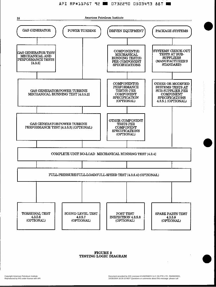
A P I RPSLLPGT 92 rn 0732290 0503493 B B T rn
34 American Petroleum Institute (7) (7) 7 I GAS GENERATOR TEST
MECHANICAL AND PERFORMANCE TESTS
L4.3.31
I COMPONErnS) I
I SPECIFICATIONS I
GAS GENERATOWPOWER TURBINE MECHANICAL RUNNING TEST [4.3.5.2]
COMPONENT(S) PERFORMANCE
TEST(S) PER COMPONENT
SPECIFICATION (OPTIONAL)
GAS GENERATOWPOWER TURBINE PERFORMANCE TEST [4.3.5.3](OPTIONAL)
I
I I
OTHER COMPONENT I TESTS PER
SPECIFICATIONS COMPONENT I (OPTIONAL) I
SYSTEMS' CHECK-OUT TESTS AT SUB-
SUPPLIERS (MANUFACTURER'S
STANDARD)
I OTHER OR MODIFIED SYSTEMS TESTS AT SUB-SUPPLIER PER
COMPONENT SPECIFICATIONS
4.3.5.1 (OPTIONAL)
I I
COMPLETE UNIT NO-LOAD MECHANICAL RUNNING TEST K4.3.41
I I
F U L L - P R E S S U S P E E D TEST E4.3.5.41 (OPTIONAL)
117 TOWIONAL TEST
(OPTIONAL) (OPTIONAL) (OPTIONAL)
POST TEST SOUND LEVEL TEST 4.3.5.6 INSPECTION 4.3.5.8 4.3.5.7
I I I I
1
SPARE PARTS TEST
(OPTIONAL) 4.3.5.9
FIGURE 2 TESTING LOGIC DIAGRAM
Copyright American Petroleum Institute Reproduced by IHS under license with API
Document provided by IHS Licensee=KVAERNER E & C (S) PTE LTD /5945820001, 10/28/2004 18:26:10 MDT Questions or comments about this message: please callthe Document Policy Group at 303-397-2295.
--``,,,,,,``,`,,`,````,`,,,,-`-`,,`,,`,`,,`---
API RP*l,LPGT 72 M 0732270 0503474 716 ~~ ~
___I RP 1lPGT Packaged Combustion Gas Turbines ~ .- 35 . _.____ ~ ~ _ _
c. Operation of bleed valves. d. Operation of anti-icing systems (when they are
furnished). e. All oil pressures, viscosities and temperatures
shall be at the same operating values recom- mended in the manufacturer’s operating instruc- tions for the specific unit under test. Lubricant consumption shall be determined. Filters and any chip detectors shall be examined at the comple- tion of testing.
f. The casings, lube oil system, fuel system and hydraulic system shall be checked for joint and connection tightness. All oil and fuel leaks shall be corrected. Air leaks adversely affecting perform- ance and posing a safety hazard in the judgement of the purchaser shall be corrected.
g. All warning, protective and control devices shall be adjusted prior to the test and employed during the test when possible.
4.3.3.3 During the gas generator mechanical run- ning and performance test, the mechanical operation of all equipment shall be satisfactory. Vibration read- ings shall not exceed the limit of paragraph 2.3.6 and/ or 2.3.6.1. The performance of the machine shall meet the criteria specified.
4.3.4 Complete Unit No-load Mechanical Running Test.
4.3.4.1 Test preparation shall be in accordance with paragraphs 4.3.4.1.1 through 4.3.4.1.11 shall be per- formed before the Complete Unit No-Load Mechani- cal Running Test is performed.
4.3.4.1.1 The contract bearings and, where practi- cal, the contract shaft seals shall be used in the package for the mechanical running test. 4.3.4.1.2 All lubricating oil pressures, viscosities, and temperatures shall be within the range of op- erating values recommended in the packager’s op- erating instructions for the specific unit being tested. For pressure lubrication systems, oil flow rates to each oil film sleeve type bearing housing shall be determined. 4.3.4.1.3 Test-stand oil filtration shall be 10 mi- crons nominal or better. Oil system components downstream of the filters shall meet the cleanliness requirements of API Standard 614 before any test is started. 4.3.4.1.4 All joints and connections shall be checked for tightness, and any leaks shall be corrected. 4.3.4.1.5 All warning, protective, and control de- vices shall be checked, and adjustments made as required. 4.3.4.1.6 For compressor applications, facilities shall be installed to prevent the entrance of oil or other debris into the compressor during the me- chanical running test. These facilities shall be in operation throughout the test. 4.3.4.1.7 Testing with the contract coupling(s) is required. After the running tests, the shrink fit of hydraulically mounted couplings shall be inspected by comparing hubhhaft match marks to ensure that the coupling hub(s) have not moved on the shaft during the tests.
4.3.4.1.8 All contract vibration probes, cables, os- cillator-demodulators, and accelerometers shall be in use during the test. 4.3.4.1.9 Shop test facilities shall include instru- mentation with the capability of continuously moni- toring, plotting and recording revolutions per minute, peak-to-peak displacement, peak accelera- tion, rms velocity, and phase angle k-y- y’). Presen- tation of vibration displacement and phase marker shall also be by oscilloscope. 4.3.4.1.10 The vibration characteristics determined by the use of the instrumentation specified in 4.3.4.1.8 and 4.3.4.1.9 shall serve as the basis for acceptance or rejection of the package L2.3.61. 4.3.4.1.11 When seismic test values are specified, vibration data (minimum and maximum values) shall be recorded and located (clock angle) in a radial plane transverse to each bearing centerline (if possible), using contract instrumentation during the test.
4.3.4.2 Speed Control. 4.3.4.2.1 The equipment shall be operated at speed increments of approximately 10 percent from mini- mum governor setting to the maximum continuous speed and run at the maximum continuous speed until bearings, lube-oil temperatures, and shaft vibrations have stabilized. 4.3.4.2.2 The output speed shall be increased to one percent below trip speed and the equipment shall be run at this speed for a maximum of 15 minutes. 4.3.4.2.3 Overspeed trip devices shall be checked and adjusted until three consecutive trip values within 1 percent of the nominal trip setting are attained. 4.3.4.2.4 The speed governor and any other speed- regulating devices shall be tested for smooth per- formance over the operating speed range. No-load stability and response to the control signal shall be checked. 4.3.4.2.5 The speed shall be reduced to the maxi- mum continuous speed, and the equipment shall be run for 4 hours. NOTE: Caution should be exercised when operating at or near critical speeds.
4.3.4.3 Test Operation. 4.3.4.3.1 During the mechanical running test, the mechanical operation of all equipment being tested and the operation of the-test instrumentation shall be satisfactory. The measured vibration levels of each component shall not exceed the specified lim- its and shall be recorded throughout the operating speed range. 4.3.4.3.2 While the equipment is operating at maxi- mum continuous speed and at other speeds that may have been specified in the test agenda, sweeps shall be made for vibration amplitudes at frequen- cies other than synchronous. As a minimum, these sweeps shall cover a frequency range from 0.25 to 8 times the maximum continuous speed but not more than 90,000 cycles per minute (1500 hertz). If
Copyright American Petroleum Institute Reproduced by IHS under license with API
Document provided by IHS Licensee=KVAERNER E & C (S) PTE LTD /5945820001, 10/28/2004 18:26:10 MDT Questions or comments about this message: please callthe Document Policy Group at 303-397-2295.
--``,,,,,,``,`,,`,````,`,,,,-`-`,,`,,`,`,,`---
L
A P I RP*lLPGT 72 m 0732290 0503475 652 W
36 I__
American Petroleum Institute
the amplitude of any discrete, nonsynchronous vi- bration exceeds 20 percent of the specified vibra- tion levels the purchaser and the packager shall mutually agree on requirements for any additional testing and on the equipment’s suitability for ship- ment. 4.3.4.3.3 The mechanical running test shall verify that lateral critical speeds conform to the require- ments of 2.4 and 2.5. For flexible-shaft machines, the first lateral critical speeds shall be determined during the mechanical running test and stamped on the nameplate followed by the word “test.” When the first critical speed cannot be determined due to damping, the calculated critical speed shall be stamped on the nameplate followed by the word “calculated” r2.71. 4.3.4.3.4 When specified, tape recordings shall be made of all real-time vibration data.
4.3.4.4 Post Test Inspection. 4.3.4.4.1 Hydrodynamic bearings shall be removed, inspected, and reassembled after the mechanical running test is completed. 4.3.4.4.2 If replacement or modification of bear- ings or seals or dismantling of the case to replace or modify other parts is required to correct mechani- cal or performance deficiencies, the initial test will not be acceptable, and the final shop tests shall be run after these replacements or corrections are made.
4.3.6 Optional Tests. When specified, the optional shop tests described in 4.3.4.1 through 4.3.4.9 shall be performed.
4.3.6.1 Auxiliary Equipment Tests. When speci- fied, auxiliary equipment such as oil systems and control system shall be tested prior to the No-load Complete Unit Mechanical Running Test. Details of the auxiliary equipment tests shall be developed jointly by the purchaser and the packager. 4.3.5.2 Gas Generatormower Turbine Mechani- cal Running Test. When specified, a separable gas generator and power turbine shall be mechanically run tested together. Testing shall be in accordance with paragraph 4.3.3. The mechanical condition of power turbines with hydrodynamic bearings shall comply with the vibration and balancing require- ments of paragraph 2.3.6. 4.3.5.3 Gas GeneratorPower Turbine Perform- ance Running Test. When specified, the gas tur- bine (gas generator and power turbine) shall be tested in accordance with ASME Power Test Codes 1 and 22 and as mutually developed by the purchaser and the packager. 4.3.5.4 Full-Pressure/Full-LadlFull-SpeedTest. When specified, the details of the full-pressure/full- loadfull-speed test shall be developed jointly by the purchaser and the packager. This test may be substi- tuted for the mechanical running test, 4.3.5.6 Electrical Generator Test.
4.3.6.5.1 When specified, the electrical generator shall be tested at the generator Vendor’s manu- facturing facility in accordance with Appendix E, Inspections and Testing of Large Electric AC Gen- erators.
0 4.3.5.5.2 When specified, the generator shall be load performance tested with the package coinci- dental with the turbineAoad equipment train me- chanical run test at packager’s facility.
B 4.3.5.6 Torsional Test. When specified, torsional brati ion measurements shall be made to verify the package analysis.
0 4.3.5.7 Sound-Level Test. The sound-level test shall be performed in accordance with ANSI 55.1, as speci- fied by the purchaser.
B 4.3.6.8 Post-Test Inspection. Dismantling, inspec- tion and reassembly of the major driven equipment, gear and the driver shall be made after satisfactory completion of the mechanical running test. Packager and purchaser shall agree to what extent the pack- age equipment shall be dismantled. Some aircraft- derivative turbine designs are impracticable for dis- mantling type inspections.
B 4.3.6.9 Spare-Parts Test. Spare parts such as ro- tors and gears shall be tested as specified by the purchaser.
4.4. Preparation for Shipment. 4.4.1 Equipment shall be suitably prepared for the type of shipment specified, including blocking of rotors when necessaxy. The preparation shall make the equip- ment suitable for 6 months of outdoor storage from the time of shipment, with no disassembly required before operation, except for inspection of bearings and seals. If storage for a longer period is specified, the pur- chaser will consult with the packager regarding the recommended procedures to be followed. 4.4.2 The packager shall provide the purchaser with the instructions necessary to preserve the integrity of the storage preparation after the equipment arrives at the job site and before start-up. 4.4.3 The equipment shall be prepared for shipment after all testing and inspection have been completed and the equipment has been approved by the pur- chaser. Preparation shall be in accordance with para- graphs 4.4.3.1 through 4.4.3.11.
4.4.3.1 Unless otherwise specified, exterior surfaces, except for machined surfaces, shall be painted with a prime coat and at least one finish coat. 4.4.3.2 Exterior machined surfaces shall be coated with a suitable rust preventative. 4.4.3.3 The interior of the rotating equipment shall be clean; free from scale, welding spatter, and for- eign objects; and sprayed or flushed with a suitable rust preventative that can be removed with solvent. 4.4.3.4 Internal steel areas of bearing housings and carbon steel oil systems’ auxiliary equipment such as reservoirs, vessels, and piping shall be coated with a suitable oil-soluble rust preventative. 4.4.3.5 Flanged openings shall be provided with metal closures at least 3/16 inch (4.8 millimeters) thick, with rubber gaskets and at least four full-diameter bolts. For studded openings, all nuts needed for the intended service shall be used to secure closures. 4.4.3.6 Threaded openings shall be provided with steel caps or round-head steel plugs in accordance with ANSI B16.11. The caps or plugs shall be of
Copyright American Petroleum Institute Reproduced by IHS under license with API
Document provided by IHS Licensee=KVAERNER E & C (S) PTE LTD /5945820001, 10/28/2004 18:26:10 MDT Questions or comments about this message: please callthe Document Policy Group at 303-397-2295.
--``,,,,,,``,`,,`,````,`,,,,-`-`,,`,,`,`,,`---
API RP*LLPGT 92 0732290 0503496 599 W
~~ ~ . ~ ~. RP AlPGT Packaged Combustion Gas Turbines 37 _ _ - ~ ~
--__
material equal to or better than that of the pressure casing. In no case shall nonmetallic (such as plastic) caps or plugs be used. 4.4.3.7 Openings that have been beveled for welding shall be provided with closures designed to prevent entrance of foreign materials and damage to the bevel. 4.4.3.8 Lifting points and lifting lugs shall be clearly identified. 4.4.3.9 The equipment shall be identified with item and serial numbers. Material shipped separately shall be identified with securely affixed, corrosion-rews- tant metal tags indicating the item and serial num- ber of the equipment for which it is intended. In addition, crated equipment shall be shipped with duplicate packing lists, one inside and one on the outside of the shipping container. 4.4.3.10 When a spare rotor is purchased, the rotor shall be prepared for unheated indoor storage for a period of a t least 3 years. The rotor shall be treated with a rust preventative and shall be housed in a vapor-barrier envelope with a slow-release vapor- phase inhibitor. The rotor shall be suitably crated for domestic or export shipment, as specified. Suitable sheeting, at least 1/8 inch (3.2 millimeters) thick,
shall be used between the rotor and the cradle at the support areas. The rotor shall not be supported at journals.
4.4.3.11 Exposed shafts and shaft couplings shall be wrapped with waterproof, moldable waxed cloth or vapor-phase-inhibitor paper. The seams shall be sealed with oilproof adhesive tape.
4.4.4 Auxiliary piping connections furnished on the purchased equipment shall be impression stamped or permanently tagged to agree with the packagers con- nection table or general arrangement drawing, service and connection designations shall be indicated.
4.4.5 Bearing assemblies shall be fully protected from the entry of moisture and dirt. If vapor-phase-inhibitor crystals in bags are installed in large cavities to absorb moisture, the bags must be attached in an accessible area for ease of removal. Where applicable, bags shall be installed in wire cages attached t o flanged covers, and bag locations shall be indicated by corrosion-resis- tant tags attached with stainless steel wire.
4.4.6 One copy of the packager’s standard installation instructions shall be packed and shipped with the equipment.
Copyright American Petroleum Institute Reproduced by IHS under license with API
Document provided by IHS Licensee=KVAERNER E & C (S) PTE LTD /5945820001, 10/28/2004 18:26:10 MDT Questions or comments about this message: please callthe Document Policy Group at 303-397-2295.
--``,,,,,,``,`,,`,````,`,,,,-`-`,,`,,`,`,,`---

38 American Petroleum Institute
SECTION 5 PACKAGER’S DATA
6.1 Proposals. 5.1.1 General. The packager shall forward the origi- nal and the specified number of copies of the proposal to the addressee stated on the inquiry documents. This proposal shall contain, as a minimum, the data speci- fied in 5.1.2 through 5.1.4, and a specific statement of compliance with the purchaser‘s inquiry specifications, and a detailed list of any exceptions specifically iden- tified as such. The packager shall provide details to evaluate any alternative designs proposed. All corre- spondence shall be clearly identified. 5.1.2 The packager shall complete and forward the Packager Drawing and Data Requirements form [Ap- pendix B] to the address(s) noted on the inquiry or order. This form shall detail the schedule for transmis- sion of drawings, curves, and data as agreed to at the time of the proposal or order as well as the number and type of copies required by the purchaser. 5.1.3 Coordination Meeting. A coordination meet- ing shall be held, preferably at the packager’s plant, within 4-6 weeks after the purchase commitment. The purchaser will propose an agenda prior to this meeting which, typically includes: a. The purchase order, scope of supply, and subvendor
b. The preliminary data sheets. c. Applicable specifications and previously agreed upon
exceptions. d. Schedules. e. Testing program. f. Main component general arrangement. g. Project administration requirements. h. Any startup, shutdown, or operating restrictions
required to protect the integrity of the equipment shall be stated [2.1.9.5].
5.1.4 Curves. The proposal shall contain a power out- put versus speed curve for rated site conditions. It should follow the format shown in Appendix B. Addi- tional curves shall be presented for conditions of speci- fied maximum and minimum site ambient tempera- ture. Curves should also show any limit condition of driven load, such as the compressor surge line. All curves shall include power deductions (or fuel increases) for inlet and exhaust pressure losses to reflect inlet/ exhaust equipment specified or proposed. When speci- fied, the curves described below shall also be fur- nished.
6.1.4.1 Speedltorque curve for power output shaft. For single shaft designs, the required starting torque; and the combined torque to load, produced by the starting device plus the turbine after light off, shall be indicated. 5.1.4.2 Incremental power output for increments of steam or water injection. The purchaser shall state the quantity and condition of injection steam avail- able. 6.1.4.3 For turbine/generator units, performance curves shall also include kilowatt output versus gas
items.
turbine ambient inlet temperature and generator power (KW) capability versus ambient or cooling fluid temperatures. 5.1.4.4 Gas turbine exhaust emissions.
5.1.5 Technical Requirement. As a minimum, the packager shall provide the following additional items in the proposal: - Maintenance and inspection requirements (2.1.7). - Spare parts listings (2.1.8). - Expected emission levels (2.1.11). - Packaged equipment (2.2.1 and 2.2.2). - Other equipment (2.2.3). - Starting restrictions (2.2.9). - Special tools and fixtures (2.2.16.1). - Lube oil and seal oil systems (2.3.5.2.2). - Materials identification (2.6.1.2). - Filter performance (3.4.2.2). - Water wash requirements (3.7.1 and 3.7.4).
B - Deviations from API 614 requirements (3.7.1 and 3.7.4).
- Fuel gas requirements (3.8.2.1 and 3.8.2.3.2). - Dual fuel system (3.8.4.5). - Waterhteam injection system (3.8.5.3). - Control system (3.9.1.5 and 3.9.2.4).
5.2 Contract Data. 5.2.1 General.
5.2.1.1 The contract information to be furnished by the packager is specified in Appendix B. Each draw- ing, bill of material, or data sheet shall have a title block in the lower right hand corner with date of certification, revision number, date, and title. 5.2.1.2 The Packager Drawing and Data Require- ment sheet shall indicate which, if any, data must be reviewed before components on that drawing can be released for purchase or manufacture. 5.2.1.3 The purchaser will return data submitted for review within two weeks after receipt, with any com- ments identified in the two categories listed below. a. Information on accessory items that are included
in the order specifications, but not on the data issued.
b. Items which are not included in the order speci- fications in effect at the time of drawing issue, but which the purchaser has requested via amended specifications.
Within two weeks of receipt of the marked up data, the packager shall issue revised data incorporating all comments and any other specified details not included in the first issue. The purchaser will review data and return with any further comments. This cycle will be repeated until the Packager receives a review issue with no comments, at which time a certified issue shall be made and stamped “final”.
Copyright American Petroleum Institute Reproduced by IHS under license with API
Document provided by IHS Licensee=KVAERNER E & C (S) PTE LTD /5945820001, 10/28/2004 18:26:10 MDT Questions or comments about this message: please callthe Document Policy Group at 303-397-2295.
--``,,,,,,``,`,,`,````,`,,,,-`-`,,`,,`,`,,`---

5.2.1.4 Return without comment does not constitute permission from purchaser for the packager to devi- ate from any requirements of the order, unless spe- cifically agreed to in writing by a change of the purchase specifications. 5.2.1.5 A complete list of all packager data shall be included with the first issue of major drawings. This list will contain titles, drawing numbers, and a sched- ule for transmission of all data the packager will furnish.
5.2.2 Drawings. The drawing(s1 furnished shall con- tain sufficient information so that when combined with the manuals covered in 5.2.5, the purchaser may prop- erly install, operate, and maintain the ordered equip- ment. Drawings shall be clearly legible, and be in accordance with ANSI Y14.2M. Details listed in Ap- pendix B shall be provided as a minimum. 5.2.3 Technical Data. Data shall be submitted, per Appendix B. Any drawing comments or specification revisions necessitating a change in the data shall be noted by the packager and will result in reissue of the completed, corrected data sheets by the purchaser as part of the order specifications. 5.2.4 Recommended Spares. The packager shall sub- mit a supplementary list of spare parts other than those included in his original proposal. This supple- mentary list shall include recommended spare parts for all equipment supplied, with cross-sectional or as- sembly type drawings, part numbers, and delivery times. Part numbers shall identify each part for inter- changeability purposes. Standard purchased items shall be identified by the original manufacturer's numbers. The packager shall forward this supplementary list to the purchaser promptly after receipt of the reviewed drawings and in time to permit order and delivery of the parts before field startup. 5.2.5 Installation, Operation, and Maintenance Manuals.
5.2.5.1 The packager shall provide sufficient written instructipns and a cross-referenced list of all draw- ings to enable the purchaser to correctly install, operate, and maintain the complete equipment or- dered. This information shall be compiled in a manual (or manuals) with an index sheet containing section titles, and a complete list of referenced and enclosed drawings by title and drawing number. The manual shall be prepared specifically for this installation and shall not by "typical." 5.2.5.2 Installation Manual. Any special informa- tion required for proper installation design that is not on the drawings shall be compiled in a manual
that is separate from operating and maintenance instructions. This manual shall be forwarded at a time mutually agreed upon in the order, but not later than the final issue of prints. The manual shall con- tain information such as special alignment or grout- ing procedures, utility specifications (including quan- tity), and all installation design data including any pertinent drawingddata specified in 5.2.2 and 5.2.3. Unless otherwise included, sketches showing the lo- cation of center of gravity and rigging provisions to permit removal of the top half of the casing, the rotor, and any subassemblies that weigh more than 300 pounds (136 kilograms) shall be furnished. 5.2.5.3 Operating and Maintenance Manual. The manual containing operating and maintenance data shall be forwarded no later than six weeks aRer the successful completion of all specified tests. The manual shall include a section to cover special in- structions for operations at specified extreme envi- ronmental conditions, such as temperatures. In addi- tion, as a minimum, it shall include:
a. As built data sheets. b. Certified site performance curves. c. All contract drawings. d. As built assembly clearances. e. An itemized parts list for all equipment supplied.
The list shall completely identify each part so that the purchaser may determine the part's in- terchangeability with other equipment furnished by the same packager. Standard purchased items shall be identified by the original manufacturer's numbers.
5.2.6 Technical Data Manual. The packager shall make the following information available for review by the purchaser within thirty days of package shipment. Reports shall be identified with a title page and shall contain copies of raw shop data (with specified witness signature) along with sample calculations (if appli- cable) and tabulation of the final test results.
a. The packager's physical and chemical data from mill reports (or certification) of critical alloy or steel pressure parts and forgings [2.6.1.2].
b. Certified shop logs of all tests r4.31. c. When specified, tape recordings of real-time vibra-
d. Technical analyses datdateral , torsional, and
tion data.
Campbell diagrams as required [2.4, 2.51.
Copyright American Petroleum Institute Reproduced by IHS under license with API
Document provided by IHS Licensee=KVAERNER E & C (S) PTE LTD /5945820001, 10/28/2004 18:26:10 MDT Questions or comments about this message: please callthe Document Policy Group at 303-397-2295.
--``,,,,,,``,`,,`,````,`,,,,-`-`,,`,,`,`,,`---

40 American Petroleum Institute
APPENDMA TYPICAL DATA SHEETS
APPLICABLE SPECIFICATIONS AND DATA SHEETS
THE LATEST REVISION OF THE FOLLOWING DOCUMENTS SHALL BECOME A PART OF "HIS RECOMMENDED PRACTICE
REFERENCE DATA
SPECIFICATION SHEET
API 11P - Packaged Reciprocating Compressors 0 API 610 - Centrifugal Pumps 0 API 611 - General Purpose Steam Turbines 0 API 613 - Special Purpose Gear Units 0 API 614 - Oil Systems 0 API 616 - Gas Turbines (Section 2 only) 0 A P I 617 - Centrifugal Compressors 0 API 618 - Reciprocating Compressors 0 API 660 - Shell & Tube Heat Exchangers 0 API 661 - Air Cooled Heat Exchangers 0 API 670 - Vibration, Bearing, & Temperature Monitors 0 API 671 - Couplings 0 API 678 - Accelerometer Based Vibration Monitors 0 ANSI C50.12 - Salient Pole Generator 0 Manufacturer Standard 0
0 0
Purchaser Specification 12.2.51 0 Noise Specifications 12.1.101 0 Emission Specifications 12.1.111 0 Third Party Certification 0 Other 0
OTHER APPLICABLE REFERENCE DRAWINGS: EQUIPMENT PLOT/GENERAL ARRANGEMENT PLAN, DRAWING NUMBER PROCESS SYSTEM DIAGRAM, DRAWING NUMBER GENERATOR POWER SYSTEM ONE LINE DIAGRAM, DRAWING NUMBER OTHER, DRAWING NUMBER
Copyright American Petroleum Institute Reproduced by IHS under license with API
Document provided by IHS Licensee=KVAERNER E & C (S) PTE LTD /5945820001, 10/28/2004 18:26:10 MDT Questions or comments about this message: please callthe Document Policy Group at 303-397-2295.
--``,,,,,,``,`,,`,````,`,,,,-`-`,,`,,`,`,,`---

A P I R P * l l P G T 92 W 0732290 0503500 8 4 T W
\PPLICABLE TO: 0 PROPOSAL 0 PURCHASE 0 AS BUILT
3FOR . 0 UNIT 3 SITE c] SERIAL NO. 3 SERVICE 0 NO. REQUIRED
3 GEOGRAPHIC LOCATiON 0 UBC SEISMIC ZONE (2.1.9.1)-
3 PACKAGER MODEL SHOP ORDER 3 DRIVER MANUFACTURER MODEL SERIAL NO. 3 GRIVEN EQUIPMENT TYPE MANUFACTURER MODEL SERIAL NO. Ii ADDITIONAL DRIVEN EQUIPMENT TYPE- MANUFACTURER c] MODEL SERIAL NO.
TYPE MANUFACTURER MODEL SERIAL NO.
3 OUTPUT REQUIRED 3OPERATlNG SPEED RANGE REQUIRED CYCLE: OREGEN 0 3MPLE 0 EXHAUST HEAT RECOVERY TYPE OF GAS TURBINE: SINGLE SHAFT MULTI SHAFT
IUTY: 0 CONTINUOUS 0 tNTERMlTTENT 0 STANDBY OPERATION (2.1.9.4) 0 ATTENDED 0 UNATTENDED
IOTE: INFORMATION TO BE COMPLETED: 0 BY PURCHASER BY PACKAGER BY PACKAGER IF NOT BY PURCHASER
LOSSES .GAS TURBINE. INCLUDING ALL ENGINE DRIVEN PARASITIC
SITE NORMAL SITE SITE RATED D U N MAX MIN
TEMP TEMP 0 DRY BULB TEMP. 'F
0 RELATIVE HUMIDLTY $5
G BAROVETER PS!A a OUTPUT, KVf (HP) ( I )
a HEAT RATE,
OUTPUT SHAFT SPEED, RPM c] INLET AIR FLOW LBSiSEC
INLET AIR SYSTEM AP,
- - -- - - -- - - -- - - --
LHV BTU!iGV(HP)-HR - - --
IN. H20 FIRING TEMP. OF
0 EXHAUST FLOW LBSiSEC (1) c] EXHAUST SYSTEM A?,
(1) INCLUDING EFFECTS FOR OSTEAM 0 WATER INJECTION
0 DRIVEN EQUIPMENT, SEE SEPARATE DATA SHEETS (XXXX)
EMISSION CONTROL AUGMENTATION
STEAM FLOW, LWHR
0 WElGHTlDlMENSlONAL LIMITATIONS
0 SPECIAL CONSIDERATIONS 0 DOMESTIC 0 EXPORT 0 EXPORT BOXING REQUIRED 0 OUTDOOil STOPAGE MORE THAN 6 MONTHS
0 OCEAN TRANSPORT PREPARATION TYPE 0 LIFT SLINGSSPREADERS BY PACKAGER
3 GEOGRAPHIC LOCATION
0 U.B.C. SEISMIC ZONE
0 INDOOR 0 OUTDOOR
0 HEATED 0 UNDER ROOF
0 UNHEATED 0 PARTIAL SiDES
0 ELEC. AREA CLASSIFICATION (2.1.9.2. 2.2.5)
GAS TURBINE AREA 0 I I
GAS TURBINE ENCLOSURE 0 I /
CONTROL PANEL 0 I I
NON-HAZARDOUS CL'GRPiDIV
0 MARINIZATION REQUIRED WINTERIZATION REQUIRED 0 TROPlCALlZATlON REQUIRED (3.10.6)
UNUSUAL CONDITIONS: 0 DUST 0 FUMES OOTHER (2.1.9.1)
0 OTHER
Copyright American Petroleum Institute Reproduced by IHS under license with API
Document provided by IHS Licensee=KVAERNER E & C (S) PTE LTD /5945820001, 10/28/2004 18:26:10 MDT Questions or comments about this message: please callthe Document Policy Group at 303-397-2295.
--``,,,,,,``,`,,`,````,`,,,,-`-`,,`,,`,`,,`---

~ __ . - . ~ -.
A P I RP*33PGT 72 0732270 0503503 786 ~-
42 American Petroleum Institute
0 UTILITY CONDITIONS
STEAM: AUX DRIVERS HEATING INLET MIN PSlG OF PSlG OF NORM PSI0 OF PSlG OF MAX PSlG OF PSlG "F EXHAUST MIN PSlG OF PSlG "F NORM PSlG OF PSlG "F MAX PSlG OF PSlG 'F
INLET MIN PSlG OF PSlG OF NORM PSlG "F PSlG OF MAX PSI0 "F PSI0 "F EXHAUST MIN PSI0 OF NORM PSlG "F MAX PSlG OF
STARTING INJECTION
ELECTRICITY (3.10.1):
MOTORS HEATING CONTROL SHUTDOWN
VOLTAGE
HERTZ
PHASE
0 TOTAL UTILITY CONSUMPTION:
COOLING WATER GPM STEAM LEVEL PSlG PSlG PSlG STEAM, NORMAL PSlG STEAM, MAX PSlG INSTRUMENT AIR ~ ~~ . SCFM . _. . .
~~
IARIES) KW K w
HEATERS Kw PURGE (AIR OR N,) SCFM
I...
TURBINE AIR EXTRACTION REQUIRED:
0 SCFM @ 0 MAXIMUM PRESSURE AVAILABLE PSlG @ 0 DISCHARGE TEMP OF 0 COMPRESSOR STAGE EXTRACTED
COOLING WATER: I TEMP. INLET OF MAX RETURN PRESS NORM PSlG DESIGN MIN RETURN PSlG MAX ALLOW A P PSlD DESIGN WATER SOURCE
INSTRUMENT AIR PRESSURE, PSIG: ~~ ~
Copyright American Petroleum Institute Reproduced by IHS under license with API
Document provided by IHS Licensee=KVAERNER E & C (S) PTE LTD /5945820001, 10/28/2004 18:26:10 MDT Questions or comments about this message: please callthe Document Policy Group at 303-397-2295.
--``,,,,,,``,`,,`,````,`,,,,-`-`,,`,,`,`,,`---
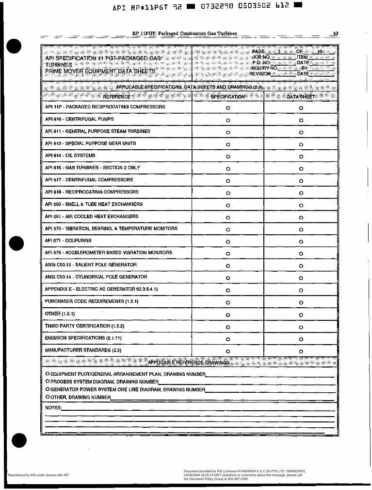
API RP*hlPGT 92 0732290 0503502 bL2
API 11P - PACKAGED RECIPROCATING COMPRESSORS 0 0
API 610 - CENTRIFUGAL PUMPS 0 0
API 611 - GENERAL PURPOSE STEAM TURBINES 0 0
API 613 - SPECIAL PURPOSE GEAR UNITS I 0 I 0
API 614 - OIL SYSTEMS 0 0
API 616 - GAS TURBINES - SECTION 2 ONLY 0 0
API 617 - CENTRIFUGAL COMPRESSORS 0 0
API 618 - RECIPROCATING COMPRESSORS 0
API 660 - SHELL & TUBE HEAT EXCHANGERS I 0 I 0
API 661 - AIR COOLED HEAT EXCHANGERS 0 0
API 670 - VIBRATION, BEARING, & TEMPERATURE MONITORS 0 0
API 671 - COUPLINGS 0 0
API 678 - ACCELEROMETER BASED VIBRATION MONITORS 0 0
ANSI C50.12 - SALIENT POLE GENERATOR 0 0
ANSI (250.14 - CYLINDRICAL POLE GENERATOR 0 0
APPENDIX E - ELECTRIC AC GENERATOR 92.3.5.4.1) 0 0
PURCHASER CODE REQUIREMENTS (1.5.1) 0 0
OTHER (1.51) 0
0 0 THIRD PARTY CERTIFICATION (1.5.2)
0
~~ ~~~ ~~
~ ~ ~
EMISSION SPECIFICATIONS (2.1 .11) 0
0 0 MANUFACTURER STANDARDS (2.3)
0
0 EQUIPMENT PLOTIGENERAL ARRANGEMENT PIAN, DRAWING NUMBER
0 PROCESS SYSTEM DIAGRAM. DRAWING NUMBER 0 GENERATOR POWER SYSTEM ONE LINE DIAGRAM, DRAWING NUMBER
0 OTHER, DRAWING NUMBER
NOTES:
Copyright American Petroleum Institute Reproduced by IHS under license with API
Document provided by IHS Licensee=KVAERNER E & C (S) PTE LTD /5945820001, 10/28/2004 18:26:10 MDT Questions or comments about this message: please callthe Document Policy Group at 303-397-2295.
--``,,,,,,``,`,,`,````,`,,,,-`-`,,`,,`,`,,`---

A P I RPaLLPGT 92 0732290 0503503 559 W
44 _- ~
American Petroleum Institute
TYPE (3.1.1) 0 MOTOR OTURBINE 0 GAS EXPANDER 0 ICE ENGINE 0 HYDRAULIC
OGAS TURBINE e! STARTER IS CLUTCHED (3.1.6)
0 STARTER RATING (3.1.2) HP 0 SHAFT TURNING DEVICE REQUIRED
0 MOTOR (3.1.4):
TYPE RATING HP MFR. MODEL HP
0 STEAM TURBINE (3.1.4):
MFR. MODEL
HP MAX STEAM FLOW LBS/HR TOTAUSTART LBS
0 GAS EXPANDER (3.1.5)
APPLICABLE SPEC.
MFR. MODEL
HP MAX GAS FLOW LBSlHR TOTAUSTART LBS
0 GAS FOR EXPANSION TURBINE:
INLET PRESSURE, PSI EXHAUST PRESS, PSI GAS TEMP., OF INLET GAS TEMP., OF EXHAUST MOLECULAR WEIGHT
SPEED CONTROL 0 GOVERNOR 0 PRESSURE REGULATOR
YES NO
MIN MAX NORMAL
INLET CONTROL VALVE FURNISHED STAINLESS STEEL PIPING MANIFOLD CARBON STEEL FLANGES
LOW SPEED CAPABILITY (FOR COMPRESSOR CLEANING)
RELIEF VALVE PRESSURE SET POINT CASING MATERIAL SEAL TYPE
-- -- Y-STRAINER WBREAKOUT FLANGES
-- -- --
PSI
IC ENGINE
TYPE 0 SPARK IGNITED 0 DIESEL APPLICABLE SPEC
MFR MODEL HP RPM 0 GAS TURBINE
APPLICABLE SPEC MFR MODEL HP RPM
OTYPE OF FOUNDATION (3.2.1.1)
0 SUITABLE FOR EPOXY GROUT (3.2.2.2)
0 BASEPLATE (3.2.3.1), SINGLE MULTIPLE
0 LEVELING PADWARGETS (3.2.3.2)
0 COLUMN MOUNTING (3.2.3.3) 0 THERMAL ISOLATION 0 EXTERNAL EXCITING FORCES (2.4.2.2)
OSUPPORT SYSTEM VALUE (2.5.2.2.A)
0 DECKING/GRATING, TYPE (3.2.3.6)
0 ENCLOSURE TYPE 0 FIRE SUPPRESSION BY CO, OFIRE SUPPRESSION BY HALON 1301
OSPECIAL DESIGN CONSIDERATIONS
0 VENTILATION FAN REDUNDANCY (3.3.4.1)
0 POSITIVE PRESSURE VENTILATION (3.3.4.1)
0 EXTERNAL DUCTING BY PURCHASER (3.3.4.4)
0 D.C. FAN REQUIRED HP
0 SEE ATTACHED API-671 DATA SHEETS
0 MANUFACTURER 0 TYPE 0 MODEL 0 GUARD SUPPLIED BY
0 MAX O.D. IN
0 HUB WEIGHT LBS
0 SPACER LENGTH IN 0 SPACER WEIGHT LBS
0 IDLING ADAPTER REQUIRED
LUBRICATION REQUIREMENTS
0 NON-LUBE 0 GREASE 0 CONT. OIL LUBE QUANTITY PER HUB LBS OR GPM
Copyright American Petroleum Institute Reproduced by IHS under license with API
Document provided by IHS Licensee=KVAERNER E & C (S) PTE LTD /5945820001, 10/28/2004 18:26:10 MDT Questions or comments about this message: please callthe Document Policy Group at 303-397-2295.
--``,,,,,,``,`,,`,````,`,,,,-`-`,,`,,`,`,,`---
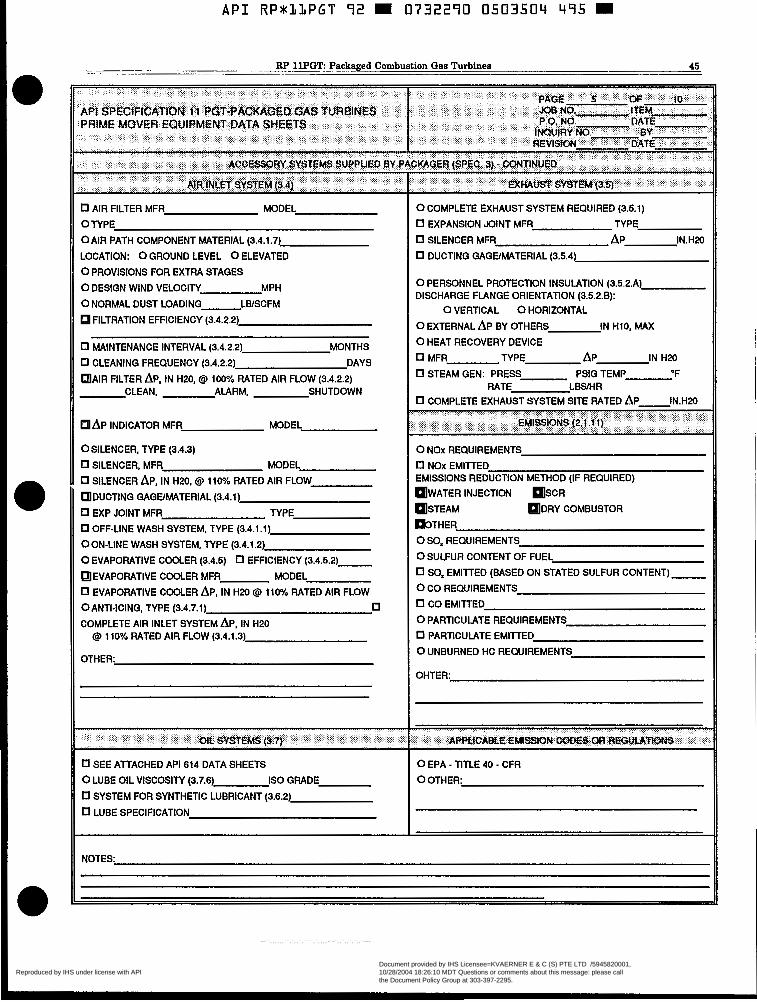
A P I RPSIJLPGT 92 0732290 0503504 495 W
~~ ~ .~ . RP 11PGTLPackFged Combustion Gas Turbines
~ ~. 45
0 AIR FILTER MFR MODEL
0 TYPE OAlR PATH COMPONENT MATERIAL (3.4.1.7)
LOCATION: 0 GROUND LEVEL 0 ELEVATED
0 PROVISIONS FOR EXTRA STAGES
0 DESIGN WIND VELOCITY MPH
0 NORMAL DUST LOADING LBlSCFM
FILTRATION EFFICIENCY (3.4.2.2)
0 MAINTENANCE INTERVAL (3.4.2.2) MONTHS
0 CLEANING FREQUENCY (3.4.2.2) DAYS
AIR FILTER AP, IN H20. @ 100% RATED AIR FLOW (3.4.2.2) CLEAN, ALARM, SHUTDOWN
A P INDICATOR MFR MODEL
OSILENCER. TYPE (3.4.3)
0 SILENCER, MFR MODEL 0 SILENCER AP, IN H20. @I 110% RATED AIR FLOW
DUCTING GAGEMATERIAL (3.4.1)
0 EXP JOINT MFR TYPE 0 OFF-LINE WASH SYSTEM, TYPE (3.4.1.1) OON-LINE WASH SYSTEM, TYPE (3.4.1.2)
0 EVAPORATIVE COOLER (3.4.5) 0 EFFICIENCY (3.4.5.2)
EVAPORATIVE COOLER MFR MODEL 0 EVAPORATIVE COOLER AP. IN H20 @ 110% RATED AIR FLOW OANTI-ICING, TYPE (3.4.7.1) 0 COMPLETE AIR INLET SYSTEM AP, IN H20
@ 110% RATED AIR FLOW (3.4.1.3)
0 SEE ATTACHED API 614 DATA SHEETS
0 LUBE OIL VISCOSITY (3.7.6) IS0 GRADE 0 SYSTEM FOR SYNTHETIC LUBRICANT (3.6.2)
0 LUBE SPECIFICATION
0 COMPLETE EXHAUST SYSTEM REQUIRED (3.5.1)
0 EXPANSION JOINT MFR TYPE
0 SILENCER MFR AP IN.H20
0 DUCTING GAGEMITERIAL (3.5.4)
0 PERSONNEL PROTECTION INSULATION (3.5.2.A) DISCHARGE FLANGE ORIENTATION (352.8):
0 EXTERNAL A P BY OTHERS IN H10, MAX
0 HEAT RECOVERY DEVICE 0 MFR TYPE AP IN H20
0 VERTICAL 0 HORIZONTAL
0 STEAM GEN: PRESS PSlG TEMP 'F RATE LBSMR
0 COMPLETE EXHAUST SYSTEM SITE RATED A P IN.H20
0 NOx REQUIREMENTS 0 NOx EMITTED EMISSIONS REDUCTION METHOD (IF REQUIRED)
WATER INJECTION SCR
STEAM DRY COMBUSTOR ~ ~ T H E R 0 SO, REQUIREMENTS
0 SULFUR CONTENT OF FUEL 0 S O x EMllTED (BASED ON STATED SULFUR CONTENT)
0 CO REQUIREMENTS 0 CO EMITTED
0 PARTICULATE REQUIREMENTS
0 PARTICULATE EMITTED 0 UNBURNED HC REQUIREMENTS
OHTER:
Copyright American Petroleum Institute Reproduced by IHS under license with API
Document provided by IHS Licensee=KVAERNER E & C (S) PTE LTD /5945820001, 10/28/2004 18:26:10 MDT Questions or comments about this message: please callthe Document Policy Group at 303-397-2295.
--``,,,,,,``,`,,`,````,`,,,,-`-`,,`,,`,`,,`---
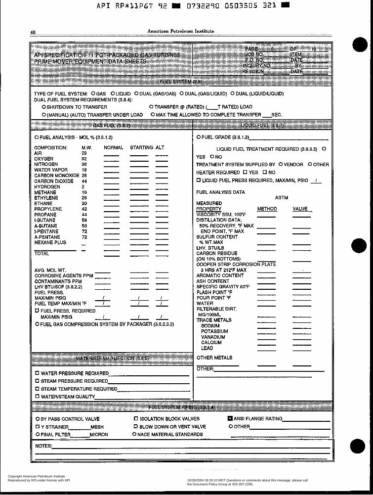
A P I RP*llPGT 92 = 0732290 0503505 321 = 46 American Petroleum Institute
TYPE OF FUEL SYSTEM: 0 GAS 0 LIQUID 0 DUAL (GASIGAS) 0 DUAL (GASILIQUID) 0 DUAL (LIQUID/LIQUID) DUAL FUEL SYSTEM REQUIREMENTS (3.8.4):
0 SHUTDOWN TO TRANSFER OTRANSFER @ (RATED) T RATED) LOAD 0 (MANUAL) (AUTO) TRANSFER UNDER LOAD 0 MAX TIME ALLOWED TO COMPLETE TRANSFER SEC.
0 FUEL ANALYSIS - MOL % (3.8.1.2)
COMPOSITION: M.W. NORMAL AIR 29 OXYGEN 32 NITROGEN 38
CARBON MONOXIDE 28 CARBON DIOXIDE 44 HYDROGEN 2 METHANE 16 ETHYLENE 26 ETHANE 30 PROPYLENE 42 PROPANE 44
WATER VAPOR l a
I-BUTANE 58 A-BUTANE 58 I-PENTANE 72 A-PENTANE HEXANE PLUS - 72
TOTAL - - -
AVO. MOL WT. CORROSIVE AGENTS PPM CONTAMINANTS PPM - LHV BTUISCF (3.8.2.2) - FUEL PRESS. MAWMIN PSI0 FUEL TEMP MAXIMIN OF - I
I -
0 FUEL PRESS. REQUIRED MAWMIN PSlG - I
0 FUEL GAS COMPRESSION SYSTEM BY PACKAGER (3.8.2.3.2)
0 WATER PRESSURE REQUIRED 0 STEAM PRESSURE REQUIRED 0 STEAM TEMPERATURE REQUIRED
0 FUEL GRADE (3.8.1.2)
LIQUID FUEL TREATMENT REQUIRED (3.8.3.2) 0 YES O N 0 TREATMENT SYSTEM SUPPLIED BY 0 VENDOR 0 OTHER
HEATER REQUIRED 0 YES 0 NO
0 LIQUID FUEL PRESS REQUIRED, MAXIMIN, PSlG
FUEL ANALYSIS DATA
MEASURED ASTM
PROPERTY METHOD VISCOSITY SSU, 100°F DISTILLATION DATA: 50% RECOVERY, OF MAX END POINT, OF M4X
SULFUR CONTENT % WT.MAX
LHV. BTUILB CARBON RESIDUE (ON 10% BOTTOMS) COOPER STRIP CORROSIOFK~~E
3 HRS AT 212F MAX AROMATIC CONTENT ASH CONTENT SPECIFIC GRAVITY 6OoF FLASH POINT "F
WATER POUR POINT 'F
FILTERABLE DIRT.
TRACE METALS MW100ML
SODIUM POTASSIUM VANADIUM CALCIUM LEAD -
OTHER METALS
nTUFR.
VALUE
0 BY PASS CONTROL VALVE 0 ISOLATION BLOCK VALVES 0 ANSI FLANGE RATING
0 Y STRAINER MESH 0 BLOW DOWN OR VENT VALVE 0 OTHER
0 FINAL FILTER MICRON 0 NACE MATERIAL STANDARDS . -
NOTES
Copyright American Petroleum Institute Reproduced by IHS under license with API
Document provided by IHS Licensee=KVAERNER E & C (S) PTE LTD /5945820001, 10/28/2004 18:26:10 MDT Questions or comments about this message: please callthe Document Policy Group at 303-397-2295.
--``,,,,,,``,`,,`,````,`,,,,-`-`,,`,,`,`,,`---

A P I RP*LLPGT 92 0732290 0503506 268
~ .. - .- ~ RP ~ 11PGT Packaged Combustion Gas Turbines 41 . ~
_ _
UNIT CONTROL PANEL POWER (3.1.0.2) OAC 0 DC UNIT CONTROL PANEL LOCATION (3.9.3.1)
0 PROCESS CONTROL SIGNAL INPUT (3.9.1.2.1) 0 LOCAL 0 REMOTE OTlME FOR AC POWER OUTAGE RIDE THROUGH (3.9.1.3)
0 FAULT TOLERANT DESIGN (3.9.1.4) VIBRATION MONITOR (3.9.4.3) 0 API 670 0 API 670 0 BLACKSTART CAPABILITY (3.9.2.3)
1. START SELECTOR, LOC/REM 0 0 0 0 0 0
2. START SEQUENCE, ENABLE 0 0 0 0 0 0
3. STOP SEQUENCE, ENABLE 0 0 0 0 0 0
4. EMERGENCY SHUTDOWN 0 0 0 0 0 0 ~~ ~
5. FAIL TO CRANK
6. FAIL TO START 0 0 0 0 0 0
7. FAIL TO IGNITE 0 0 0 0 0 0
8. READY TO LOAD 0 0 0 0 0 0
9. HOUR METER 0 0 0 0 0 0
10. FIRED START COUNTER
11. START AlTEMPT COUNTER 0 0 0 0 0 0
12. SPEED SELECTOR, AUTO/MANUAL Q 0 0 0 0 0
13. SPEED, 0.0. 0 0 0 0 0 0 ~ ~~
14. SPEED, P.T.
15. SPEED, RAISELOWER 0 0 0 0 0 0
16. SPEED, SET POINT Q 0 0 0 0 0
17. UNDERSPEED, G.G. 0 0 0 0 0 0
NOTES: II
H
Copyright American Petroleum Institute Reproduced by IHS under license with API
Document provided by IHS Licensee=KVAERNER E & C (S) PTE LTD /5945820001, 10/28/2004 18:26:10 MDT Questions or comments about this message: please callthe Document Policy Group at 303-397-2295.
--``,,,,,,``,`,,`,````,`,,,,-`-`,,`,,`,`,,`---
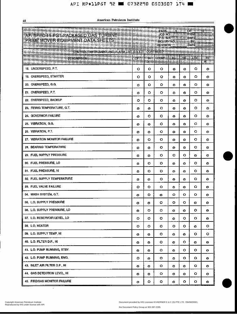
48 American Petroleum Institute
18. UNDERSPEED, P.T. 0
19. OVERSPEED, STARTER 0
20. OVERSPEED, G.G. 0
21. OVERSPEED, P.T. 0
22. OVERSPEED, BACKUP 0
23. FIRING TEMPERATURE, G.T. 0
24. GOVERNOR FAILURE 0
25. VIBRATION, G.G. 0
26. VIBRATION, P.T. 0
27. VIBRATION MONITOR FAILURE 0
28. BEARING TEMPERATURE 0
29. FUEL SUPPLY PRESSURE 0
30. FUEL PRESSURE, LO 0
0
0 0 0 0 0 0
0 0 0 0 0 0
0 0 0 0 0 0
0 0 0 0 0 0
0 0 0 0 0 0
31. FUEL PRESSURE, HI
32. FUEL SUPPLY TEMPERATURE
33. FUEL VALVE FAILURE
34. WASH SYSTEM, G.T.
35. L.O. SUPPLY PRESSURE
0 - 0
0
-
0
0 0 0 0
36. L.O. SUPPLY PRESSURE, LO 0 0 0
37. L.O. RESERVOIR LEVEL, LO 0 0 0
38. L.O. HEATER 0 0 0
39. L.0. SUPPLY TEMP, HI 0 0 0
40. L.O. FILTER D.P., HI 0 0 0
41. L.O. PUMP RUNNING, STBY. 0 0 0
42. L.O. PUMP RUNNING, EMG. 0 0 0
43. INLET AIR FILTER D.P., HI 0 0 0
~~
0
0 0
0 0 0
0 0 0
0 0 0
0 0 0
0 0 0
0 0 0
0 0 0
0 1 0 1 0 ~~~ ~ ~
44. GAS DETECTION LEVEL, HI
45. FIRE/GAS MONITOR FAILURE l o l o l o I 0 l o l o l 0
Copyright American Petroleum Institute Reproduced by IHS under license with API
Document provided by IHS Licensee=KVAERNER E & C (S) PTE LTD /5945820001, 10/28/2004 18:26:10 MDT Questions or comments about this message: please callthe Document Policy Group at 303-397-2295.
--``,,,,,,``,`,,`,````,`,,,,-`-`,,`,,`,`,,`---

A P I R P M l L P G T 92 m 0732290 0503508 030 m
~ ~ ~ . ~~ R P l E G T Packaged Combustion Gas Turbines 49
46. Enclosure Temperature, Hi 0
47. Fire System Disabled 0 01 o I 0 l o l o l 0 40. Fire I 0 49. Fire/Gas System D i s d w g d 0
50. Control Voltage, Lo 0
51. f3attm-y Voltage. Lo 0
52. Battery Charger Failure 0
53. Reset/Lamp Test 0
54. Horn Silence 0
0
0
0
0
0
- - - -
0
0
0 0 0
AL = ALARM GG = GAS GENERATOR MAN = MANUAL SD = SHUTDOWN AUTO =AUTOMATIC GT = GAS TURBINE OPT = OPTIONAL STBY = STANDBY CON = CONTROL IND = INDICATOR PRESS = PRESSURE TEMP = TEMPERATURE D.P. = DIFFERENTIAL PRESSURE L.O. = LUBE OIL PT = POWER TURBINE EMG = EMERGENCY LOC = LOCAL REM = REMOTE
NOTES
Copyright American Petroleum Institute Reproduced by IHS under license with API
Document provided by IHS Licensee=KVAERNER E & C (S) PTE LTD /5945820001, 10/28/2004 18:26:10 MDT Questions or comments about this message: please callthe Document Policy Group at 303-397-2295.
--``,,,,,,``,`,,`,````,`,,,,-`-`,,`,,`,`,,`---

60 American Petroleum Institute
SHOP INSPECTION AND TESTS: (4.1) I 0 MATERIALS INSPECTION REQUIREMENTS (4.2.2)
SHOP INSPECTION (4.1.4) I 0 I 0 I 0 I ORADIOGRAPHY REQUIRED FOR
HYDROSTATIC (4.3.2) I I 0 I 0 I OMAGNETIC PARTICLE REQUIRED FOR
GAS GENERATOR (4.3.3) I 0 I 0 I 0 I OLlQUlD PENETRANT REQUIRED FOR
COMPLETE UNIT - NO LOAD 0 0 0 0 UNITRASONIC REQUIRED FOR (4.3.4)
AUXILIARY EQUIPMENT (4.3.5.1) 0 0 0 0 OTHER:
GAS TURBINE MECH. RUN 0 0 0 (4.3.5.2)
GAS TURBINE PERFORM (4.3.5.3) 0 0 0 NOTES:
---
--- COMPLETE UNIT - PERF. (4.3.5.4) 0 0 0 --- ELECTRIC GENERATOR (4.3.5.5) 0 0 0
TORSIOGRAPH (4.3.5.6) 0 0 0
SOUND LEVEL (4.3.5.7) 0 0 0
--- ---
POST TEST INSPECTION (4.3.5.7)
SPARE PARTS (4.3.5.0)
0 0 0
l o 1 0 I o I 0 0 0
0 0 0 ---
Copyright American Petroleum Institute Reproduced by IHS under license with API
Document provided by IHS Licensee=KVAERNER E & C (S) PTE LTD /5945820001, 10/28/2004 18:26:10 MDT Questions or comments about this message: please callthe Document Policy Group at 303-397-2295.
--``,,,,,,``,`,,`,````,`,,,,-`-`,,`,,`,`,,`---

API RP*LLPGT 92 m 0732290 05035~0 799 m
. ~- -. RP 1lPGT Packaged Combustion Gas Turbines 51 ~ __I I_- -__~
.
Copyright American Petroleum Institute Reproduced by IHS under license with API
Document provided by IHS Licensee=KVAERNER E & C (S) PTE LTD /5945820001, 10/28/2004 18:26:10 MDT Questions or comments about this message: please callthe Document Policy Group at 303-397-2295.
--``,,,,,,``,`,,`,````,`,,,,-`-`,,`,,`,`,,`---
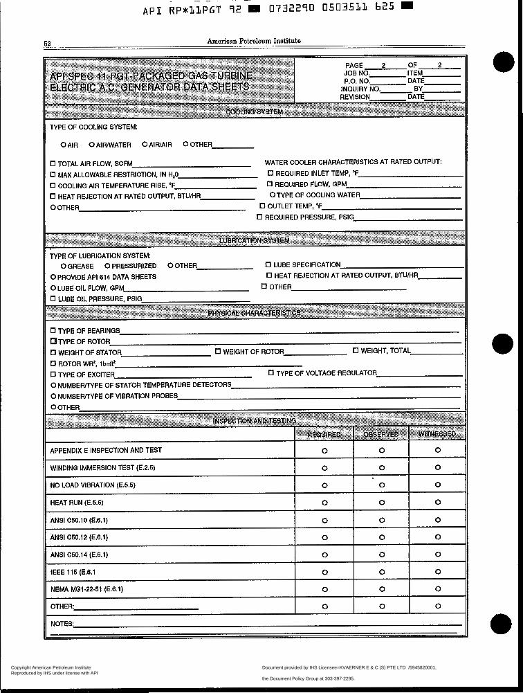
-- 62 American Petroleum Institute
TYPE OF COOLING SYSTEM:
0 AIR 0 AIFUWATER 0 AlWAlR 0 OTHER
0 TOTAL AIR FLOW, SCFM WATER COOLER CHARACTERISTICS AT RATED OUTPUT
0 MAX ALLOWABLE RESTRICTION, IN H,O 0 REQUIRED INLET TEMP, OF
0 COOLING AIR TEMPERATURE RISE, OF 0 REQUIRED FLOW, GPM
0 HEAT REJECTION AT RATED OUTPUT, BTUlHR OTYPE OF COOLING WATER
0 OTHER 0 OUTLET TEMP, OF
0 REQUIRED PRESSURE, PSlG
TYPE OF LUBRICATION SYSTEM: 0 GREASE 0 PRESSURIZED 0 OTHER (7 LUBE SPECIFICATION
0 PROVIDE API 614 DATA SHEETS 0 HEAT REJECTION AT RATED OUTPUT, BTU/HR
0 LUBE OIL FLOW, GPM 0 OTHER
0 TYPE OF BEARINGS TYPE OF ROTOR
0 WEIGHT OF STATOR 0 WEIGHT OF ROTOR 0 WEIGHT, TOTAL
0 ROTOR WR', Ib=@ 0 TYPE OF EXCITER 0 TYPE OF VOLTAGE REGULATOR 0 NUMBERIPIPE OF STATOR TEMPERATURE DETECTORS-
0 NUMBEWYPE OF VIBRATION PROBES
APPENDIX E INSPECTION AND TEST 0 0 0
WINDING IMMERSION TEST (E.2.5) 0 0 0
NO LOAD VIBRATION (E.5.5) 0 0 0
HEAT RUN (E.5.6) 0 0 0
ANSI C50.10 (E.6.1) 0 0 0
ANSI (250.12 (E.6.1) 0 0 0
ANSI C50.14 (E.6.1) 0 0 0
IEEE 115 (E.6.1 0 0 0
NEMA MGI-22-51 (E.6.1) 0 0 0
OTHER 0 0 0
NOTES:
L
Copyright American Petroleum Institute Reproduced by IHS under license with API
Document provided by IHS Licensee=KVAERNER E & C (S) PTE LTD /5945820001, 10/28/2004 18:26:10 MDT Questions or comments about this message: please callthe Document Policy Group at 303-397-2295.
--``,,,,,,``,`,,`,````,`,,,,-`-`,,`,,`,`,,`---

A P I RP*LLPGT 92 W 0732290 0503512 561 W
_ I _ I _ ~
RP LlPGT Packaged Combustion-Gas Turbines ~ ~ .____~ -___ -_ 53 . .. -~ - ~ ~~ . . -
APPENDMB TYPICAL JOB NO. ITEM NO.
PACKAGER DRAWING AND PURCHASE ORDER NO. DATE
DATA REQUIREMENTS REQUISITION NO. DATE INQUIRY NO. DATE
PAGE 1 OF 3 BY
FOR REVISION
SITE UNIT
SERVICE NO. REQUIRED
Pmpcsal. Bidder shall furnish - copies of data for all items indicated by an X.
Reviewb Packager shall furnish - copies and - transparencies of drawings and data indicated.
Finalb Packager shall furnish - cap* and - transparencies of drawings and data indicated. Packager shall furnish -operating and maintenance manuals.
Final-Received from packager Final-Due from packagep
DISTRIBUTION Review-Returned to packager RECORD Review-Received from packager
Review-Oue from packagef
r I I I I I I ' f ' w o s a l drawilyls and data do not have to be certified or as built. Typical data &an be doarty IdenMW as such. Vurchasor w i H indicate In lhlt column Me time frame for submisrh of matetiah using nomendalure @van a1 the end of the form. eBkJd@r shall complete these two columns to reflect his actual distribution scheduk and I n c l u d e thls form w#h hir proporPI. Copyright American Petroleum Institute
Reproduced by IHS under license with API Document provided by IHS Licensee=KVAERNER E & C (S) PTE LTD /5945820001, 10/28/2004 18:26:10 MDT Questions or comments about this message: please callthe Document Policy Group at 303-397-2295.
--``,,,,,,``,`,,`,````,`,,,,-`-`,,`,,`,`,,`---

54 American Petroleum Institute
TYPICAL JOB No. ITEM NO.
PACKAGER DRAWING AND PURCHASE ORDER NO. DATE
DATA REQUIREMENTS REQUISITION NO. DATE INQUIRY NO. DATE PAGE OF BY
FOR REVISION
SERVICE NO. REQUIRED
B i e r shall furnish - copies of data for all items ind i ted by an X.
I R e v i d Packager shall furnish - copies and - transparencies of drawings and data indicated.
Packager shall furnish - copies and - transparencies of drawings and data indi ted. Packager shall fumlsh - operating and maintenance manuals.
FinaCRecelved from packager FinaCDue from packagef
DISTRIBUTION Revlew-Returned to packager RECORD Review-Received from packager
Revlew-Oue from packagef
DESCRIPTION
28. Inlet Pressure Drop Versus Site Rated Power Loss. 29. Exhaust Pressure Drop Versus Site Rated Power Loss.
30. Power Turbine Output Shaft Speed Versus Torque Curve. 31. Heat Rate Correction Factors.
I I 1 I 32. Anti-icing Derate (bleed alr operation). I I I I I I 33. Generator Output Performance Curve.
34. Centrifugal Compressor Performance - Allowing Minimum 4% Site Power Reserve.
35. Centrifugal Pump Performance - Allowing Mlnlmum 3% Site Power Reserve.
36. Lateral Critical Analysis Report. I I I I 37. Torslonal Critical Analvsls Report. I I I I I I
38. Stiffness Map. 39. Transient Torsional Analysis.
40. Allowable Flange Loading(s). 41. Alignment Diagram.
43. Test Procedures. 44. Hydrostatic Test Logs.
45. Mechankal Run Test Logs. 46. Test Logs.
I 1 I I I I I I I 1
Copyright American Petroleum Institute Reproduced by IHS under license with API
Document provided by IHS Licensee=KVAERNER E & C (S) PTE LTD /5945820001, 10/28/2004 18:26:10 MDT Questions or comments about this message: please callthe Document Policy Group at 303-397-2295.
--``,,,,,,``,`,,`,````,`,,,,-`-`,,`,,`,`,,`---

API RP*KLLPGT 92 0732290 0503534 334 W
.I_- - ~ .~ RP 11PGT Packaged Combugion3s Turbines - -. a ~
55 .- .- -
TYPICAL PACKAGER DRAWING AND
DATA REQUIREMENTS
JOB NO. ITEM NO.
PAGE OF BY DATE REV. NO.
r ! Proposal. Bidder shall furnish - copies of data for all items indicated by an X.
Reviewb Packager shall furnish - copies and - transparencies of drawings and data indicated.
FinaP Packager shall furnish -copies and - transparencies of drawings and data indicated. Packager shall furnish - operating and maintenance manuals.
FinaCReceived from packager
DlSTRlBUTlON RECORD
Review-Due from packagef
I
1 55. Spare Parts Recommendation. I I I 56. Fabrication and Delivew Schedule. 1 I I
.- I I
I 58. List of Special Tools for Maintenance. ! I 57. Packing List. !
59. Foundation Plan/Anchor Bolt Layout.
1 60. Lift Drawinas. r i I 61. User’s List. I I I I I I
1
1 62. Operational Restrictions. ! I
I I I I
Proposal dram’ngs and data do not have lo be certilled or as built. Typical data shalt be clearly identifii as such. .Purchaser will indicate in thls column the time frame for submisslon of materials using the nomenclature gken at Me end of the form. Wdder shall complete these two columns lo rellsct his actual distribution schedule and Include this form with his proposal.
Notes: 1. Send all drawings and data to
2. Ail drawings and data must show project, appropriation, purchase order, and item numbers in addition to the plant location and unit. In addition to the copies specified above, one set of the drawingsfinstructions necessary for field installa- tion must be forwarded with the shipment.
3. See expanded description of specified items below.
Nomenclature: %number of weeks prior to shipment. F-number of weeks after firm order. D-number of weeks after receipt of approved drawings.
Packager Date Packager Reference Signature
(Signature acknowledges receipt of all instructions)
Copyright American Petroleum Institute Reproduced by IHS under license with API
Document provided by IHS Licensee=KVAERNER E & C (S) PTE LTD /5945820001, 10/28/2004 18:26:10 MDT Questions or comments about this message: please callthe Document Policy Group at 303-397-2295.
--``,,,,,,``,`,,`,````,`,,,,-`-`,,`,,`,`,,`---
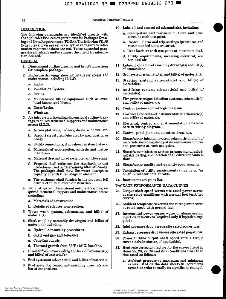
66 American Petroleum Institute
nESCRIPTION The following paragraphs are identified directly with the applicable line item requirements for Packager Draw- ing and Data Requirements (PDDR). The following PDDR Schedules shown are self-descriptive in regard to infor- mation required; others are not. These expanded para- graphs will clarify and/or suggest the intent for informa- tion desired. GENERAL 1. Dimensional outline drawing and list of connections
2. Enclosure drawings showing details for access and for complete package.
maintenance including r2.2.31: a. Lights. b. Ventilation System. c. Drains. d. Maintenance lifting equipment such as over-
e. DoorsLocks. F. Windows.
3. Air inlet system including dimensional outline draw- ings, required structural supports and maintenance access E2.2.21. a. Access platforms, ladders, doors, windows, etc. b. Support structure, if elevated by specification or
c. Utility connections, if not shown in item 1 above. d. Materials of construction, controls and instru-
e. Material description of each inlet air filter stage. f. Proposal shall reference the standards or test
procedures used in determining filter efficiency. The packager shall state the water absorption capacity of each filter stage or element.
g. The packager shall furnish in his proposal full details of inlet silencer construction.
4. Exhaust system dimensional outline drawings, re- quired structural support and maintenance access including: a. Materials of construction. b. Details of silencer construction.
material(s).
material(s) including: a. Hydraulic mounting procedures. b. Shaft end gap and tolerance. c. Coupling guards. d. Thermal growth from 59°F (15°C) baseline.
7. Bleed air/cooling air sealing and leak-off schematic(s) and bill(s) of material(s).
8. Fuel system(s) schematic(s) and bill(s) of materials. 9. Fuel system(s) component assembly drawings and
head beams and blocks.
design.
mentation.
6. Water wash system, schematics, and bill(s) of
6. Shaft coupling assembly drawing(s) and bill(s) of
list of connections.
10. Lube-oil and control-oil schematic(s), including: a. Steady-state and transient oil flows and pres-
b. Control, alarm and trip settings (pressures and
c. Heat loads at each use point at maximum load. d. Utility requirements, including electrical, wa-
11. Lube-oil and control assembly drawinds) and list(s)
12. Seal system schematic(s), and bill(s) of material(s). 13. Starting system, schematids) and bill(s) of
14. Anti-Icing system, schematic(s) and bill(s) of
16. Fire protectiodgas detection systems, schematic(s)
16. Control system control logic diagram. 17. Electrical, control and instrumentation schematic(s)
18. Electrical, control and instrumentation intercon-
19. Control panel plan and elevation drawings. 20. Steadwater injection system schematic and bill of
materials, including steady-state and transient flows and pressures at each use point.
21. Steadwater injection system arrangement, includ- ing size, rating, and location of all customer connec- tions.
sures at each use point.
recommended temperatures).
ter, and air.
of connections.
material(s1.
material(s1.
and bill(s) of materials.
and bill(s) of materials.
nection wiring diagram.
22. Steadwater quality and quantity requirements. 23. Tabulation of utility requirements (may be on "as
24. Instrument set point list.
BCKAGE PWFOR- 26. Output shaft speed versus site rated power curves
at site rated conditions with normal fuel (certified curves).
26. Ambient temperature versus site rated power curve at rated speed with normal fuel.
27. Incremental power versus water or steam system injection rate curves (required only if injection sup- plied).
built" purchaser data sheets).
28. Inlet pressure drop versus site rated power loss. 29. Exhaust pressure drop versus site rated power loss. 30. Power turbine output shaft speed versus torque
curve (include starter, if applicable). 31. Heat rate correction factors for the curves listed in
Items 25,26,27,28 and 29 at conditions other than size rated as follows: a. Ambient pressure to maximum and minimum
values listed on the data sheets in increments agreed at order (usually no significant change).
Copyright American Petroleum Institute Reproduced by IHS under license with API
Document provided by IHS Licensee=KVAERNER E & C (S) PTE LTD /5945820001, 10/28/2004 18:26:10 MDT Questions or comments about this message: please callthe Document Policy Group at 303-397-2295.
--``,,,,,,``,`,,`,````,`,,,,-`-`,,`,,`,`,,`---
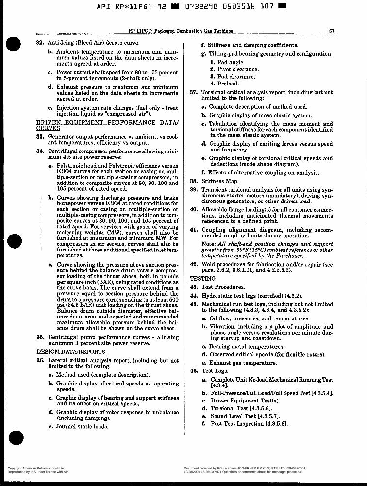
A P I R P * L l P G T 92 M 0732290 0503536 307 W
__- ~
~~
RP 1lPGT PackagedCom>uation Gas Turbines 57 . - . -. . ~~ ~ ~ . _ _ _
32. Anti-Icing (Bleed Air) derate curve. b. Ambient temperature to maximum and mini-
mum values listed on the data sheets in incre- ments agreed a t order.
c. Power output shaft speed from 80 to 105 percent in 5-percent increments (2-shaft only).
d. Exhaust pressure to maximum and minimum values listed on the data sheets in increments agreed at order.
e. Injection system rate changes (fuel only - treat injection liquid as "compressed air").
DRIVEN E Q U I P l l l E N T O R P I i A N C E D m :URVES 33. Generator output performance vs ambient, vs cool-
ant temperatures, efficiency vs output. 34. Centrifugal compressor performance allowing mini-
mum 4% site power reserve: a. Polytropic head and Polytropic efficiency versus
ICFM curves for each section or casing on mul- tiple-section or multiple-casing compressors, in addition to composite curves a t 80,90,100 and 105 percent of rated speed.
b. Curves showing discharge pressure and brake horsepower versus ICFM at rated conditions for each section or casing on multiple-section or multiple-casing compressors, in addition to com- posite curves at 80,90, 100, and 105 percent of rated speed. For services with gases of varying molecular weights (MW), curves shall also be furnished at maximum and minimum MW. For compressors in air service, curves shall also be furnished at three additional specified inlet tem- peratures.
c. Curve showing the pressure above suction pres- sure behind the balance drum versus compres- sor loading of the thrust shoes, both in pounds per square inch (BAR), using rated conditions as the curve basis. The curve shall extend from a pressure equal to section pressure behind the drum to a pressure corresponding to at least 500 psi (34.5 BAR) unit loading on the thrust shoes. Balance drum outside diameter, effective bal- ance drum area, and expected and recommended maximum allowable pressure behind the bal- ance drum shall be shown on the curve sheet.
35. Centrifugal pump performance curves - allowing - 36. Lateral critical analysis report, including but not
minimum 3 percent site power reserve.
limited to the following: a. Method used (complete description). b. Graphic display of critical speeds vs. operating
c. Graphic display of bearing and support stiffness
d. Graphic display of rotor response to unbalance
e. Journal static loads.
speeds.
and its effect on critical speeds.
(including damping).
f. Stiffness and damping coefficients. g. Tilting-pad bearing geometry and configuration:
1. Pad angle. 2. Pivot clearance. 3. Pad clearance. 4. Preload.
37. Torsional critical analysis report, including but not limited to the following: a Complete description of method used. b. Graphic display of mass elastic system. c. Tabulation identifying the mass moment and
torsional stiffness for each component identified in the mass elastic system.
d. Graphic display of exciting forces versus speed and frequency.
e. Graphic display of torsional critical speeds and deflections (mode shape diagram).
f. Effects of alternative coupling on analysis. 38. Stiffness Map. 39. Transient torsional analysis for all units using syn-
chronous starter motors (mandatory), driving syn- chronous generators, or other driven load.
40. Allowable flange loading(s1 for all customer connec- tions, including anticipated thermal movements referenced to a defined point.
41. Coupling alignment diagram, including recom- mended coupling limits during operation. Note: All shaft-end position changes and support growths from 59OF (15OC) ambient reference or other temperature specified by the Purchaser.
42. Weld procedures for fabrication andfor repair (see para. 2.6.2, 3.6.1.11, and 4.2.2.5.2).
TESTING 43. Test Procedures. 44. Hydrostatic test logs (certified) (4.3.2). 45. Mechanical run test logs, including but not limited
to the following (4.3.3, 4.3.4, and 4.3.5.2): a Oil flow, pressures, and temperatures. b. Vibration, including x-y plot of amplitude and
phase angle versus revolutions per minute dur- ing startup and coastdown.
c. Bearing metal temperatures. d Observed critical speeds (for flexible rotors). e. Exhaust gas temperature.
46. Test Logs.
14.3.41. a Complete Unit No-load Mechanical Running Test
b. Ful l -Pressdul l Load/Full Speed Test 14.3.5.41. c. Driven Equipment Tesffs). d. Torsional Test 14.3.5.61. e. Sound Level Test 14.3.5.71. f. Post Test Inspection [4.3.5.8].
Copyright American Petroleum Institute Reproduced by IHS under license with API
Document provided by IHS Licensee=KVAERNER E & C (S) PTE LTD /5945820001, 10/28/2004 18:26:10 MDT Questions or comments about this message: please callthe Document Policy Group at 303-397-2295.
--``,,,,,,``,`,,`,````,`,,,,-`-`,,`,,`,`,,`---

A P I RP833PGT 72 0732270 0503537 f ly3
68 American Petroleum Institute
g. Spare Parts Test [4.3.5.91. 47. Performance test logs and report in accordance with
ASME PTC-22, Section 6 (1985) as supplemented by ASME PTC-1 (1986) subpart K, para. 3.30 and 3.31 14.3.5.3 and 4.3.5.41.
48. Non-destructive test procedures as itemized on P.O. data sheets or PDDR form.
49. Procedures for any special or optional test (see para 2.6.1.7, 4.2, and 4.3.4).
60. Mill test reports (certified) of items as agreed in the pre-commitment or pre-inspection meetingts).
DATAlMANUALS 61. As-built data sheets. 62. As-built dimensions (including nominal dimensions
with design tolerances) and data for the following listed parts: a. Shaft or sleeve diameters at:
1. Thrust collar (for separate collars). 2. Each seal component. 3. Each wheel (for “stacked” rotors) or bladed
4. Each interstage labyrinth. 6. Each journal bearing.
and O.D.
disc.
b. Each wheel or disc bore (for “stacked” rotors)
c. Each labyrinth or seal-ring bore. d. Thrust-collar bore (for separate collars). e. Each journal-bearing ID. f. Thrust-bearing concentricity (axial runout). g. Metallurgy and heat treatment for:
1. Shaft. 2. Impellers or bladed discs. 3. Thrust collar. 4. Blades, vanes, and nozzles.
63. Installation manual describing the following (see 5.2.5.2): Section 1 - Installation. a. Storage. b. Foundation. c. Grouting. d. Setting equipment, rigging procedures, compo-
e. Alignment. f. Piping recommendations, including allowable
flange loads. g. Composite outline drawings for driveddriven-
equipment train, including anchor-bolt locations. h. Dismantling clearances.
following (see 5.2.5.3):
nent weights, and listing diagram.
64. Operating and maintenance manuals describing the
Section 2 - Operation. a. Startup. b. Normal shutdown. c. Emergency shutdown. d. Operating limits. e. Lube-oil recommendations. f. Routine operational procedures. Section 3 - Disassembly and Reassembly Instruc- tions: a. Rotor in casing. b. Rotor unstacking and restacking procedures. c. Journal bearings (for tilting-pad bearings, pro-
vide “go/no-gon dimensions with tolerances for three-step plug gauges).
d. Thrust bearing. e. Seals (maximum and minimum clearances). f. Thrust collar. g. Wheel reblading procedures. h. Boring procedures and torque values. Section 4 - Performance Curves: (Data) a. Shaft speed versus site rated power. b. Ambient temperature versus site rated power. c. Output power shaft speedltorque curve. d. Incremental power outputlsystem injection rate
e. Heat correction factors. f. First-stage pressure versus thrust. Section 5 - Vibration Analysis Data; per item 28, 29,30, 33 above. Section 6 - As-Built Data. a. As-built data sheets. b. As-built dimensions or data (see 47 above). c. Hydrostatic test logs (see 44 above). d. Mechanical run test logs (see 45 above). Section 7 - Drawing and Data. a. Certified dimensional outline drawing and list
b. Cross-sectional drawing and bill of materials. c. Rotor drawingts) and bill of materials. d. Thrust-bearing assembly drawing and bill of ma-
e. Journal-bearing assembly drawing and bill of
f. Seal-component drawing and bill of materials. g. Lube-oil schematic and bill of materials. h. Lube-oil arrangement drawing and bill of mate-
i. Lube-oil component drawings and data.
curve (optional).
of connections.
terials.
materials.
rials.
Copyright American Petroleum Institute Reproduced by IHS under license with API
Document provided by IHS Licensee=KVAERNER E & C (S) PTE LTD /5945820001, 10/28/2004 18:26:10 MDT Questions or comments about this message: please callthe Document Policy Group at 303-397-2295.
--``,,,,,,``,`,,`,````,`,,,,-`-`,,`,,`,`,,`---
A P I RP*11PGT 92 0732290 0503518 T8T W
~~ ~ . - -_.___~ RP 11PGT Packaged Combustion Gas Turbines 59 .-
j. Electrical and instrumentation schematics and
k. Electrical and instrumentation arrangement bill of materials.
drawing and list of connections.
1. Control- and trip-system drawings and data.
m. Trip- and throttle-valve construction drawing.
55. Spare parts lists with stocking level recommenda- tion for commissioningktartup, and operational requirements.
dor buyouts and milestones. 66. Fabrication and delivery schedule, including ven-
57. Shipping list, including all major components that will ship separately.
58. List of special tools furnished for maintenance. Iden- tify any metric items included in the offering.
59. Foundation plan, including data per 51. Section 1.e above, and information per para 3.2.
60. Instrument set-point list. 61. Lift drawings: Sketches indicating methods of lift-
ing the assembled machineb) and major compo- nents. If "typical" drawings, schematics, and bill of materials are used, they shall be marked up to show correct weight and dimension data, and to reflect the actual equipment and scope proposed.
62. User list: A list of similar machines installed and operating under analogous conditions to that pro- posed.
63. Operational restrictions.
Copyright American Petroleum Institute Reproduced by IHS under license with API
Document provided by IHS Licensee=KVAERNER E & C (S) PTE LTD /5945820001, 10/28/2004 18:26:10 MDT Questions or comments about this message: please callthe Document Policy Group at 303-397-2295.
--``,,,,,,``,`,,`,````,`,,,,-`-`,,`,,`,`,,`---

A P I RP833PGT 92 m 0732290 0503539 93b m
60 American Petroleum Institute
APPENDIX C PROCEDURE FOR DETERNIINATION OF RESIDUAL UNBALANCE
C.1 Scope. This appendix describes the procedure to be used to determine residual unbalance in machine rotors. Although some balancing machines may be set up to read out the exact amount of unbalance, the calibra- tion can be in error. The only sure method of determin- ing residual unbalance is to test the rotor with a known amount of unbalance. (3.2 Definition. Residual unbalance is the amount of unbalance remaining in a rotor after balancing. Unless otherwise specified, it shall be expressed in ounce-inches. C.3 Maximum Allowable Residual Unbalance.
C.3.1 The maximum allowable residual unbalance per plane shall be calculated using the equation in 2.3.6.6 of this procedure. C.3.2 If the actual static weight load on each journal is not known, assume that the total rotor weight is equally supported by the bearings. For example, a two- bearing rotor weighing 6000 pounds would be assumed to impose a static weight load of 3000 pounds on each journal.
C.4 Residual Unbalance Check. C.4.1 General.
C.4.1.1 When the balancing-machine readings indi- cate that the rotor has been balanced to within the specified tolerance, a residual unbalance check shall be performed before the rotor is removed from the balancing machine. C.4.1.2 To check residual unbalance, a known trial weight is attached to the rotor sequentially in six equally spaced radial positions, each at the same radius. The check is run in each correction plane, and the readings in each plane are plotted on a graph, using the procedure specified in (3.4.2.
(2.4.2 Procedure. C.4.2.1 Select a trial weight and radius that will be equivalent to between one and two times the maxi- mum allowable residual unbalance (that is, if Urn is 2 ounce-inches, the trial weight should cause 9-4 ounce-inches of unbalance). (3.4.2.2 Starting at the last known heavy spot in each correction plane, mark off the specified number of radial positions (six or twelve) in equal (60- or 30- degree) increments around the rotor. Add the trial weight to the last known heavy spot in one place. If the rotor has been balanced very precisely and the final heavy spot cannot be determined, add the trial weight to any one of the marked radial positions. C.4.2.3 To verify that an appropriate trial weight has been selected, operate the balancing machine and note the units of unbalance indicated on the meter. If the meter pegs, a smaller trial weight should be used. If little or no meter reading results, a larger trial weight should be used. (Little or no meter reading also generally indicates that the rotor was not balanced precisely enough. ), If the trial weight was added to the heavy spot the first meter reading should be at least twice as much as the last
reading taken before the trial weight was added. All checks must be run using one sensitivity range on the balancing machine.
C.4.2.4 Locate the weight at each of the equally spaced positions in turn, and record the amount of unbalance indicated on the meter for each position. C.4.2.6 Plot the readings on the residual unbalance work sheet and calculate the amount of residual unbal- ance. The maximum meter reading occurs when the trial weight is added at the rotor's heavy spot; the minimum reading occurs when the trial weight is op- posite the heavy spot. Thus, the plotted readings should form an approximately sinusoidal curve. An average of the maximum and minimum meter readings repre- sents the effect of the trial weight. One-half the sinu- soidal variation represents the effect of the residual unbalance. C.4.2.6 Repeat the steps described in C.4.2.1 through C.4.2.5 for each balance plane. This procedure shall not be considered complete until the readings have been plotted and the residual unbalance has been cal- culated for each balancing plane. If the specified maxi- mum allowable residual unbalance has been exceeded in any balance plane, the rotor shall be balanced more precisely and checked again. If a correction is made in any balance plane, the residual unbalance check shall be repeated in all planes.
C.6 Example. Using twelve trial weight positions, run a residual unbalance check on a centrifugal pump that operates at 3600 revolutions per minute. The two-bear- ing rotor is symmetrical and weighs 1800 pounds. The journal static weight load W is approximately one- half the total weight of the rotor, or 900 pounds. There- fore, the maximum allowable residual unbalance in each plane is calculated as follows:
4 w (4)(900) urn= =- - - ___ N 3600
= 1 ounce-inch
The trial weight should be between 1 and 2 ounce- inches. In this case, 1 ounce-inch is selected. The results of the trial weight runs are plotted in Figure C-1. The trial weight's effect (z) on the meter readings can be calculated as the average of the maximum and minimum readings. The maximum reading shown in Figure C-1 is 9 and the minimum reading is 7; therefore, z = 8. The average meter reading is equivalent to the trial unbalance. A trial unbalance of 1 ounce-inch was se- lected, so a meter reading of 8 represents 1 ounce-inch. The residual unbalance's effect (y) on the meter reading is represented on the graph by one-half the sinusoidal variation, or one-half the difference between the maxi- mum and minimum readings. Therefore, y = (9-7)/2 = 1. The one unit of residual unbalance indicated in the meter readings can now be converted to residual unbal- ance in ounce-inches as follows:
y X Trial unbalance weight U = z
Copyright American Petroleum Institute Reproduced by IHS under license with API
Document provided by IHS Licensee=KVAERNER E & C (S) PTE LTD /5945820001, 10/28/2004 18:26:10 MDT Questions or comments about this message: please callthe Document Policy Group at 303-397-2295.
--``,,,,,,``,`,,`,````,`,,,,-`-`,,`,,`,`,,`---

API RP*LLPGT 92 = 0732290 0503520 638
. ~ s- ~~
- . RP 1lPGT: Packaged Combustion Gas Turbines 61 - ~ I _ ~ -
Where: U Y
z
= residual unbalance, in ounce-inches. = effect of residual unbalance on the meter read-
ing (one-half the difference between the maxi- mum and minimum meter readings).
= effect of the trial unbalance weight on the meter reading (one-half the sum of the maxi- mum and minimum meter readings).
In the example,
1 X 1 ounce-inch
8 u = = 0.125 ounce-inch
This is less than the maximum allowable residual unbal- ance of 1 ounce-inch calculated at the beginning of the procedure.
..- 0 Y)
c zl c .- - CI
P 10 .- e 8 c s
10
9
RESIDUAL UNBALANCE WORK SHEET Rotor speed (N)3600rpm
Journal stalk weight of rotor (W)=Ib.(kg)
Balance toierance-l&-oz.-in. (0-mm) (See note.)
Trial weight 0 1.0 oz..in. (g.mm)
,
Max. reading - Mln. reading =@ 1.0 2
Max. readlng + Mln. reading =@)a 2
Resldual unbalance = @-LC x @ 1 . 0 = 0 . o z . . i n . (g-mm)
@) 8.0
1 2 3 4 5 8 7 8 9 1 0 1 1 1 2 1
Angular positlon of trlal weight Note: If not specified. balance tolerance is 4WIN 02.-in. (6350WIN gmm).
Wllnessed
Rlght Plane
FIGURE C-1 SAMPLE PLOT AND CALCULATION OF RESIDUAL UNBALANCE
Copyright American Petroleum Institute Reproduced by IHS under license with API
Document provided by IHS Licensee=KVAERNER E & C (S) PTE LTD /5945820001, 10/28/2004 18:26:10 MDT Questions or comments about this message: please callthe Document Policy Group at 303-397-2295.
--``,,,,,,``,`,,`,````,`,,,,-`-`,,`,,`,`,,`---
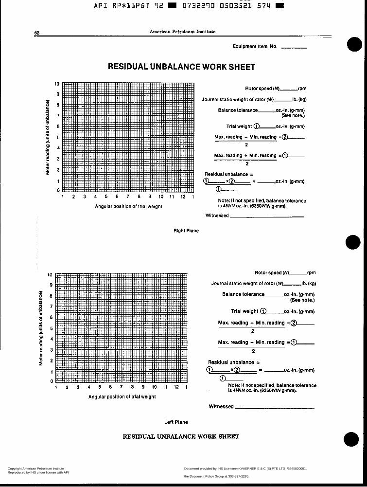
62 American Petroleum Institute
Equipment item No.
RESIDUAL UNBALANCE WORK SHEET
Rotor speed (N)-rprn
Journal static weight of rotor (Wj-lb. (kg)
Balance tolerance-02.-In. (gmm) (See note.)
Trial weight @ 02.-In. (grnrn)
Max. reading - Min. reading =@ 2
Max. reading + Mln. reading -0- 2
Residual unbalance =
1 2 3 4 5 6 7 0 9 1 0 1 1 1 2 1 Note: i f not specified, balance tolerance
Angular position of trial weight is 4 WIN 02.-in. (6350WIN grnrn).
Witnessed
10
9
0
7
6
5
4
3
2
1
0 1 2 3 4 5 6 7 0 9 1 0 1 1 1 2 1
w Note: If not specified, balance tolerance Is 4 WIN 02.-in. (6350WIN g-rnrn).
Angular position of trial weight
Witnessed
Left Plane
RESIDUAL UNBALANCE WORK SHEET
Right Plane
Rotor speed (N)-rprn
Journal static weight of rotor (Wj-ib. (kg)
Balance tolerance 02.-in. (g-mm) (See note.)
Trial weight @ 02.-in. (g-mm)
Max. readlng - Min. reading =@ 2
Max. reading + Mln. reading -0 2
Residual unbalance = @ x@- - - -oz.-in. (gmm)
/i\
Copyright American Petroleum Institute Reproduced by IHS under license with API
Document provided by IHS Licensee=KVAERNER E & C (S) PTE LTD /5945820001, 10/28/2004 18:26:10 MDT Questions or comments about this message: please callthe Document Policy Group at 303-397-2295.
--``,,,,,,``,`,,`,````,`,,,,-`-`,,`,,`,`,,`---
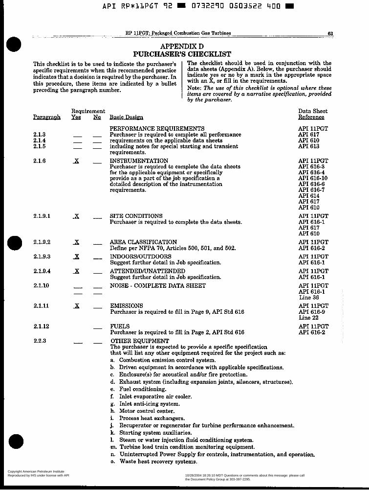
A P I RPsLLPGT 92 W 0732290 0503522 400
~ . . ~. ..- RP 1lPGT Packaged Combustion-Gas Turbines 63 __ __ ~ ~ . _ -
APPENDIX D PURCHASER’S CHECKLIST
This checklist is to be used to indicate the purchaser’s specific requirements when this recommended practice
The checklist should be used in conjunction with the
this procedure, these items are indicated by a bullet indicate yes Or no by a mark in the appropriate space indicates that a decision is required by the purchaser. In data sheets (Appendix A). Below, the Purchaser should
with an X, or fill in the requirements.
preceding the paragraph number. Note: The use of this checklist is optional where these items are covered by a narrative specification, provided
Paragl.aDh
2.1.3 2.1.4 2.1.5
2.1.6
2.1.9.1
2.1.9.2
2.1.9.3
2.1.9.4
2.1.10
2.1.11
2.1.12
2.2.3
Reauirement
x
x
x x x - -
x
-
’ by the purchaser.
Basic Design
PERFORMANCE REQUIREMENTS Purchaser is required to complete all performance requirements on the applicable data sheets including notes for special starting and transient requirements. INSTRUMENTATION Purchaser is required to complete the data sheets for the applicable equipment or specifically provide as a part of the job specification a detailed description of the instrumentation requirements.
SITE CONDITIONS Purchaser is required to complete the data sheets.
AREA CLASSIFICATION Define per NFPA 70, Articles 500, 501, and 502. INDOORS/OUTDOORS Suggest further detail in Job specification. ATTENDEDLJNATTENDED Suggest further detail in Job specification. NOISE - COMPLETE DATA SHEET
EMISSIONS Purchaser is required to fill in Page 9, API Std 616
FUELS Purchaser is required to fill in Page 2, A P I Std 616 OTHER EQUIPMENT The purchaser is expected to provide a specific specification that will list any other equipment required for the project such as: a. Combustion emission control system. b. Driven equipment in accordance with applicable specifications. c. Enclosure(s) for acoustical andlor fire protection. d. Exhaust system (including expansion joints, silencers, structures). e. Fuel conditioning. f. Inlet evaporative air cooler. g. Inlet anti-icing system. h. Motor control center. i. Process heat exchangers.
Data Sheet Reference API llPGT API 617 API 610 API 613
API llPGT API 616-3 API 616-4 API 616-10 API 616-6 API 616-7 API 614 API 617 API 610 API llPGT
API 617 API 610 A P I llPGT
API llPGT
API llPGT
API llPGT
Line 36 A P I llPGT
Line 22 API llPGT
API 616-1
API 616-2
API 616-1
API 616-1
API 616-1
API 616-9
API 616-2
- j. Recuperator or regenerator for turbine performance enhancement. k. Starting system auxiliaries. 1. Steam or water injection fluid conditioning system. .m. Turbine load train condition monitoring equipment. n. Uninterrupted Power Supply for controls, instrumentation, and operation. 0. Waste heat recovery systems.
Copyright American Petroleum Institute Reproduced by IHS under license with API
Document provided by IHS Licensee=KVAERNER E & C (S) PTE LTD /5945820001, 10/28/2004 18:26:10 MDT Questions or comments about this message: please callthe Document Policy Group at 303-397-2295.
--``,,,,,,``,`,,`,````,`,,,,-`-`,,`,,`,`,,`---

A P I R P * I I P G T 92 m 0732290 0503523 347
64 American Petroleum Institute
ParaeraDh
2.2.5
2.2.6
2.2.14
2.2.16.1
2.2.17
2.3.1.2
2.3.2.2
2.3.2.3
2.3.4.1
2.3.4.3
2.3.5.2.2
2.3.5.2.3
2.3.5.3.2
2.3.5.4.2
2.3.5.4.4
2.3.5.4.5 2.4.2.2
Requirement yes&
MOTORS AND ELECTRICAL COMPONENTS The purchaser is required to fill in electrical requirements on data sheet area requirement and utilities available. OPERATING SPEED RANGE Speed Range, if known, is to be filled in. If not known, the process requirement limits should be explained in the Job Specification. STEAM AND/OR WATER INJECTION The purchaser is to fill in injection requirements and include in the job specification any special requirements for power or emissions. SPECIAL TOOLS AND FIXTURES Purchaser is to specify when vendor is to quote special tools as a part of the initial supply of the package. COMPARTMENT ENCLOSURE It is important for the purchaser to inform the packager of the enclosure requirements including noise (Par 2.1.10), and site conditions (Par 2.1.9). GAS TURBINE DESIGN The job specification should explain to the purchaser the order of importance of governing specifications (Par 1.3). COUPLINGS Specify coupling requirements. IDLING ADAPTER Specify if idling adapter is required for running mechanical test. LOAD GEAR DESIGN Purchaser is to specify what specifications apply to the main load gear. GENERATOR MINIMUM LOAD For applications where long term operation at low power levels are expected, this requirement should be shown on data sheet and explained in job specification. COMBINED LUBE AND SEAL OIL SYSTEMS Separate or combined lube oiVseal systems are to be stated. Note: where seal systems are required (or preferred) that do not require oil,-the purchaser should detail requirements in the job specification. COMPRESSOR PERFORMANCE Performance/operating conditions are to be detailed on the compressor data sheets. PUMP PERFORMANCE Performance/operating conditions are to be detailed on the pump data sheets. RATING REQUIREMENTS Show ratings on data sheets.
GENERATOR POWER SYSTEM Purchaser will provide a Generator Power System one line diagram. GENERATOR TESTING PER APPENDIX E EXCITING FORCES The purchaser should advise the packager of any external natural frequencies or exciting frequencies that may be excited by or may excite the natural frequency of the rotating equipment. These external forces and frequencies should be explained in the job specification.
Data Sheet Reference
API 616-5 API llPGT
API 616-1 616-3
API 616-1
API llPGT
API 616-1
API llPGT
API 616 API 671 API 616 API 671 API 616 API 613 API llPGT API llPGT
API 617 API 614
API 617
API 610
ANSI 50.13 ANSI 50.14 API llPGT API llPGT
API llPGT
Copyright American Petroleum Institute Reproduced by IHS under license with API
Document provided by IHS Licensee=KVAERNER E & C (S) PTE LTD /5945820001, 10/28/2004 18:26:10 MDT Questions or comments about this message: please callthe Document Policy Group at 303-397-2295.
--``,,,,,,``,`,,`,````,`,,,,-`-`,,`,,`,`,,`---
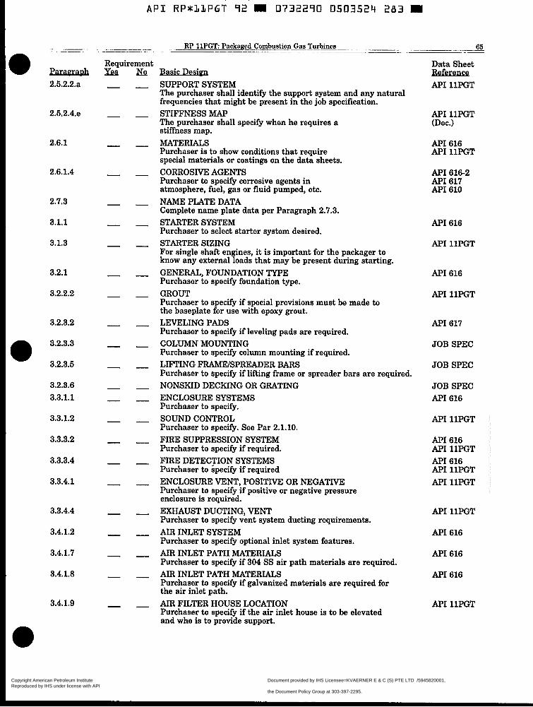
A P I R P * l L P G T 92 0732290 0503524 283
.~ ~- . ~-
ParaeraDh 2.5.2.2.a
2.5.2.4.e
2.6.1
2.6.1.4
2.7.3
3.1.1
3.1.3
3.2.1
3.2.2.2
3.2.3.2
3.2.3.3
3.2.3.5
3.2.3.6 3.3.1.1
3.3.1.2
3.3.3.2
3.3.3.4
3.3.4.1
3.3.4.4
3.4.1.2
3.4.1.7
3.4.1.8
3.4.1.9
RP 11PGT Packaged Combustion Gas Turbines ~~ 65 - ~ - ..
SUPPORT SYSTEM The purchaser shall identify the support system and any natural frequencies that might be present in the job specification. STIFFNESS MAP The purchaser shall specify when he requires a stiffness map. MATERIALS Purchaser is to show conditions that require special materials or coatings on the data sheets. CORROSIVE AGENTS Purchaser to specify corrosive agents in atmosphere, fuel, gas or fluid pumped, etc. NAME PLATE DATA Complete name plate data per Paragraph 2.7.3. STARTER SYSTEM Purchaser to select starter system desired. STARTER SIZING For single shaft engines, it is important for the packager to know any external loads that may be present during starting. GENERAL, FOUNDATION TYPE Purchaser to specify foundation type. GROUT Purchaser to specify if special provisions must be made to the baseplate for use with epoxy grout. LEVELING PADS Purchaser to specify if leveling pads are required. COLUMN MOUNTING Purchaser to specify column mounting if required. LIFTING FRAhlEISPREADER BARS Purchaser to specify if lifting frame or spreader bars are required. NONSKID DECKING OR GRATING ENCLOSURE SYSTEMS Purchaser to specify. SOUND CONTROL Purchaser to specify. See Par 2.1.10. FIRE SUPPRESSION SYSTEM Purchaser to specify if required. FIRE DETECTION SYSTEMS Purchaser to specify if required ENCLOSURE VENT, POSITNE OR hiGATIVE Purchaser to specify if positive or negative pressure enclosure is required. EXHAUST DUCTING, VENT Purchaser to specify vent system ducting requirements. AIR INLET SYSTEM Purchaser to specify optional inlet system features. AIR INLET PATH MATERIALS Purchaser to specify if 304 SS air path materials are required. AIR INLET PATH MATERIALS Purchaser to specify if galvanized materials are required for the air inlet path. AIR FILTER HOUSE LOCATION Purchaser to specify if the air inlet house is to be elevated and who is to provide support.
Data Sheet Reference API llPGT
API llPGT (Doc.)
API 616 API llPGT
API 616-2 API 617 API 610
AF'I 616
API llPGT
API 616
API llPGT
API 617
JOB SPEC
JOB SPEC
JOB SPEC API 616
API llPGT
API 616 API llPGT API 616 API llPGT API llPGT
API llPGT
API 616
API 616
API 616
API llPGT
Copyright American Petroleum Institute Reproduced by IHS under license with API
Document provided by IHS Licensee=KVAERNER E & C (S) PTE LTD /5945820001, 10/28/2004 18:26:10 MDT Questions or comments about this message: please callthe Document Policy Group at 303-397-2295.
--``,,,,,,``,`,,`,````,`,,,,-`-`,,`,,`,`,,`---

A P I RP*LLPGT 92 W 0732290 0503525 L I T M
66 American Petroleum Institute
ParaeraDh 3.4.2.1
3.4.3.1
3.4.5.1
3.4.5.7
3.4.6.2
3.4.7.1
3.5.1
3.5.2
3.6.5.1
3.6.5.2
3.7.6
3.8.1.2
3.8.2.2
3.8.2.3.2
3.8.4.1
3.8.5.1
3.8.5.2
3.9.1.1
3.9.1.2.1
3.9.1.3
3.9.1.4
3.9.2.3
3.9.3.1
3.10.1
Requirement yea& D e b
TYPE OF AIR INLET FILTER Purchaser to specify. SILENCER Purchaser to specify. See Par. 2.1.10. EVAPORATIVE COOLING Purchaser to specify. ACCESS REQUIREMENTS Purchaser to specify if walkways, hand rails, and ladders are required to provide access to coolers. WATER WASH SYSTEM Purchaser to specify if water wash system is required.
Purchaser to specify if anti-icing system is required. CYCLE APPLICATION Purchaser to indicate turbine cycle (simple or recuperated) EXHAUST SYSTEM SPECIAL REQUIREMENTS Purchaser to specify. PROCESS PIPING Purchaser is to specify the extent of process piping required. PIPING REVIEW Purchaser to specify amount of piping/ducting and auxiliary hardware that is to be reviewed by the packager. OIL CHARACTERISTICS Purchaser to show lube oil preferred in job spec. FUEL COMPOSITION Purchaser to show fuel analysis. RANGE OF HEATING VALVES Purchaser to show fuel analysis. FUEL GAS COMPRESSION Purchaser to state fuel gas pressure available and if compression is required, who provides the compression system. DUAL FUEL Purchaser to specify. NOX SUPPRESSION Purchaser to specify requirements. WATEWSTEAM INJECTION The purchaser will specify the level of NOX suppression desired. ELECTRICAL AREA CLASSIFICATION Purchaser to specify the electrical area classification for controls and instrumentation. CONTROL SIGNAL Purchaser to specify. A. C. POWER INTERRUPTION TIME PERIOD Purchaser to specify length of time of operation during loss of A.C. power. CONTROL SYSTEM REDUNDANCY Purchaser to specify if redundant control is required. STARTING WITHOUT A.C. UTILITY Purchaser to specify if black start capability is required. INSTRUMENT AND CONTROL PANEL Purchaser to specify in job specifications the control panel(s) and instrument requirements. ELECTRICAL (UTILITY) Purchaser to specify electrical utilities available.
ANTI-ICING SYSTEM
Data Sheet Reference API 616
API 616-1
API 616-9
API llPGT
API llPGT
API 616-9
API 616-1
API 616-9
JOB SPEC
JOB SPEC
JOB SPEC API 616-10 API 616-2
API 616-2
API 616-2 JOB SPEC
API 616-2
API 616-1 API 616-9 API llPGT
API llPGT
API 616-3
API 616
API 616
API llPGT
API llPGT
API 616-5
Copyright American Petroleum Institute Reproduced by IHS under license with API
Document provided by IHS Licensee=KVAERNER E & C (S) PTE LTD /5945820001, 10/28/2004 18:26:10 MDT Questions or comments about this message: please callthe Document Policy Group at 303-397-2295.
--``,,,,,,``,`,,`,````,`,,,,-`-`,,`,,`,`,,`---

API RP*LLPGT 92 H 0732290 050352b 05b W
RP 11PGT Packaged Combustion Gas Turbines 67
ParamaDh 3.10.2
3.10.6
4.1.4
4.2.1.1.a
4.2.1.1.e
4.2.1.3
4.2.2.1
4.2.3.3
4.2.3.4
4.3.2.2 4.3.4.3.4
4.3.5
4.3.5.5.1
4.3.5.5.2
4.4.1
4.4.3.10
5.1.4 5.2.6
E.5.6 E.6.1
E.6.3.1
Requirement Data Sheet Reference
DC POWER API 616-5 Purchaser to specify requirements. TROPICAL LOCATION API 616-5 Purchaser to specify when tropical treatment is required. INSPECTI0NI"ESTING API 616-10 Purchaser to specify extent of participation in testing and inspections. MATERIAL, CERTIFICATION API llPGT Purchaser to specify. APPDX B. CLEARANCES API llPGT Purchaser to specify if required. APPDX B. SURFACE/SUBSURFACE EXAMINATION API 616-10 Purchaser to specify. INSPECTION CRITERIA API 616-10 Purchaser to specify. CLEANLINESS INSPECTION API 616-10 Purchaser to specify. HARDNESS VERIFICATION API 616-10 Purchaser to specify. GAS TURBINE CASING HYDROTESTING API- 1 lPGT
Purchaser to specify. OPTIONAL TEST API llPGT Purchaser to specify.
TAPE RECORDINGS * REAL TIME API 616-10
4.3.5.1 Auxiliary Equipment Test 4.3.5.2 Gas GeneratorPower Turbine Mechanical Running Test 4.3.5.3 Gas GeneratorPower Turbine Performance Running Test 4.3.5.4 Full-Pressure/Eull-Load/Full Speed Test 4.3.5.5 Electrical Generator Teat 4.3.5.6 Torsional Test 4.3.5.7 Sound-Level Test 4.3.5.8 Post Test Inspection 4.3.5.9 Spare Parts Test
ELECTRICAL GENERATOR TESTING The purchaser is to specify that the generator shall be tested in accordance with Appendix E. LOAD PERFORMANCE TESTED The purchaser is to specify when the generator is to be load performance tested with turbine driver. LONG TIME STORAGE Purchaser to specify storage. SPARE ROTOR STORAGE Purchaser to specify storage. CURVES TECHNICAL DATA MANUAL Purchaser to specify if tape recordings of real time vibration data and optional test reports are and when required [Appendix B]. TEST RUN AT RATED TEMPERATURE TESTING GENERATORS Purchaser to specify which specification the generator will be tested in accordance with. GENERATOR TO BE WARMED UP Purchaser to specify if generator is to be warmed up to rated stator and rotor temperatures.
ANSI 50.14
ANSI 55.1
API llPGT
API llPGT
API 616-1
A P I 616-1
API llPGT
API llPGT API llPGT
API llPGT
Copyright American Petroleum Institute Reproduced by IHS under license with API
Document provided by IHS Licensee=KVAERNER E & C (S) PTE LTD /5945820001, 10/28/2004 18:26:10 MDT Questions or comments about this message: please callthe Document Policy Group at 303-397-2295.
--``,,,,,,``,`,,`,````,`,,,,-`-`,,`,,`,`,,`---

A P I RP*lLPGT 92 0732290 0503527 T92 W
68 American Petroleum Institute
APPENDIX E INSPECTION AND TESTING OF ELECTRIC AC GENERATORS
E.1 Scope and Conditions. E.l.l This Appendix covers minimum requirements for inspection and shop testing of AC generators in production services. E.1.2 The inspection and testing requirements stated herein are those that shall be performed at the gen- erator manufacturing facility prior to final assembly of the completed generator unit. The basic electrical design of the generator shall be in accordance with the applicable requirements of NEMA MG1-22 and the ANSI C50.10, C50.12, C50.13, and C50.14 Standards. Mechanical design qualities shall be equivalent to those required in the A P I RP 546.
E.1.3 Acceptance by purchaser of shop tests shall not constitute a waiver of requirements to meet field tests, if any, as specified in Purchaser’s Quotation Request or Data Sheets. E.1.4 The generator manufacturer/supplier shall be identified as the VENDOR throughout this Appendix.
E.2 Inspection. E.2.1 Purchaser shall have access to all VENDOR quality control (QC) data and records pertaining to the purchase order, and may inspect or observe any manu- facturing operation at any time during the manufac- ture. [4.1] E.2.2 VENDOR shall record the following data or dimensions during manufacture, and make the records available for review by purchaser’s inspector:
E.2.2.1 Diameter of shaft journals at center and both ends of the bearing (three readings per journal). E.2.2.2 Bore diameter of bearings, vertical and hori- zontal, at both ends of the bearing (at least four readings per bearing). E.2.2.3 Runouts of coupling face, outside diameter, and hub when specified to be mounted by VENDOR. E.2.2.4 Runout (magnitude and position of the high point) of the rotor journals, and at a location on the shaft aqjacent to the rotor core, before and after the core or poles are mounted on the shaft. E.2.2.6 Air gap at a minimum of three locations (90 degrees apart) on both ends. Repeat with rotor ro- tated a half-revolution. E.2.2.6 Residual unbalance values and location of balance weights placement on each shaft component during the rotor balance (weight, radial distance, and angular position oriented with respect to angu- lar reference, such as a keyway). E.2.2.7 All test and nondestructive examination re- sults. E.2.2.8 All nonconformances (corrected or uncorrected). This includes repair of: (1) rotor, stator or exciter insulation (2) interturn insulation (3) rotor or stator cores (4) castings or forgings (5) bearing babbitt or insulation
Uncorrected nonconformances must be documented and approved by VENDOR Engineering and Quality Control.
E.2.3 Purchaser shall have the opportunity to exam- ine parts (for dimensions and runout) on an observed basis to ensure compliance with the drawings in the following areas (where applicable) as a minimum [4.2.1.3al:
E.2.3.1 Rotor bearing journals, shaft-fan and shaft- coupling fits, and mounting fits for rotor laminations andor pole pieces. E.2.3.2 Exciter-to-rotor mounting flange, centering rabbet, and bolt circle spacing. E.2.3.3 Pole piece-to-rotor attachment and locking means, where applicable. E.2.3.4 Bearing clearance, fit of bearing outside di- ameter to bearing housing, and bearing bracket fit. On radial or axial registered fits check roundness, concentricity, and runout. On insulated bearings check roundness, contact area, and electrical resis- tance of the insulation. E.2.3.5 On totally enclosed machines, check that all frame fits are sealed or gasketed and have no gaps which would allow entrance of dust or water. E.2.3.6 Stator bore length and diameter, rotor core length and maximum pole diameter, and air gap. E.2.3.7 Retaining ring fit-up tolerance.
E.2.4 The purchaser shall have the opportunity to observe the complete stator core iron and winding before the insulation sealinghoating process is begun. E.2.5 When specified, form-wound stators shall be given a winding immersion test in accordance with NEMA MG 1-20.48. Dielectric absorption and insula- tion resistance tests shall be made a t 1000 VDC. The minimum acceptable insulation resistance shall be 50 megohms. E.2.6 During manufacturing, VENDOR shall perform the following electrical tests and record all pertinent data.
E.2.6.1 Surge comparison tests in accordance with IEEE 522 shall be made on coils to check turn-to- turn insulation after assembly into stator core, wedg- ing, and bracing of end turns, but before making up coil-to-coil connections. Peak test voltage shall be a t least rated stator voltage: 1.414 X VLL, where Vu is the rated line-to-line voltage. VENDOR standard test voltage is acceptable if it exceeds the value given. E.2.6.2 Prior to assembly of synchronous genera- tors, resistance to field pole windings shall be tested to prove equal resistance. Maximum variation in pole resistance shall not exceed 2 percent. E.2.6.3 After field poles are connected, 120 volt, AC power shall be applied to the field winding to check for shorted turns. Voltages across poles shall not vary by more than 10 percent. On units which will not be run-tested in the factory, a polarity test shall be made on the field poles.
Copyright American Petroleum Institute Reproduced by IHS under license with API
Document provided by IHS Licensee=KVAERNER E & C (S) PTE LTD /5945820001, 10/28/2004 18:26:10 MDT Questions or comments about this message: please callthe Document Policy Group at 303-397-2295.
--``,,,,,,``,`,,`,````,`,,,,-`-`,,`,,`,`,,`---

A P I RP*:LLPGT 92 m 0732290 0503528 929 m
E.2.7 VENDOR shall make available the records of all items listed in E.2.2 and E.2.3, balance data, residual unbalance records, all tests, and verification of compli- ance with E.3. These will be reviewed by the PUR- CHASER prior to release for shipment [4.2.1.1].
E.3 Balance Requirements. E.3.1 Rotors shall be dynamically balanced. The use of solder or similar deposits is not acceptable. Parent metal removed to achieve balance shall be drilled out in a way that does not affect the structural strength of the rotor; chiseling or sawing is not permitted. Rotor balance shall be done with rotor supported on its shaft journals. Rotors in generators rated 1500 rpm syn- chronous speed and higher shall be balanced after protective coating of all parts. E.3.2 Rotors with keyed couplings shall be balanced with half key(s1 in place. A half key used for balancing shall be dynamically equivalent to a half key which completely fills the keyway.
E.3.2.1 The balancing machine shall have a resolu- tion of half, or less of the maximum allowable re- sidual unbalance defined in E.3.2.4. All rotor balanc- ing shall be done on the same balancing machine at 800 to 1000 rpm unless specifically approved other- wise by the Purchaser. E.3.2.2 All components to be added, such as fans or an exciter, shall be pre-balanced separately (to lim- its consistent with the equation given in E.3.2.4, for that component) before mounting on the rotor. E.3.2.3 Balance corrections shall be made with fans removed unless otherwise specifically approved by Purchaser. Fans shall then be installed and correc- tions made to fans only. The actual balance correc- tion weight, radius, and angular location, and the balance machine reading, shall be recorded during each balance iteration. E.3.2.4 After balancing, the maximum allowable re- sidual unbalance per correction plane shall be deter- mined as follows:
U,*X = 4WN (Equation E.l) In SI units, this converts to:
U,, = 6350 WN Where
Unmax = residual unbalance, in 02.-in (gram- millimeters) per plane
revolutions per minute W = journal static weight load, in pounds
(kilograms) E.3.3 The rotor's actual residual unbalance in each plane shall be documented. At least six points shall be plotted. Plots from this procedure shall accompany the test report and shall be furnished to purchaser prior to release for shipment [Appendix C]. E.3.4 Trim-balancing is not acceptable during the ma- chine running tests. Balance weights shall not be changed or added after the dynamic balance effort has been completed. Any subsequent rebalancing requires a repeat of the rotor shaft balance effort.
N = equipment synchronous speed, in
E.3.5 Coupling hub(s) specified to be mounted by the VENDOR shall be rechecked for balance on the rotor at completion of the final rotor-fan balance C2.3.2.61. If the rotor unbalance exceeds the allowable unbalance (4Wm per plane) after the coupling hub is mounted, the VENDOR and Purchaser shall mutually agree on the cause of the excess unbalance and the corrective action to be taken. In no case shall unbalance, due to the addition of the coupling, be corrected in the main body of the rotor, fan assemblies, etc. If coupling solo (idler) plates (allowing the machine to run uncoupled) are required, they shall be mounted with the coupling after final rotor-fan balance.
E.4 Test Preparation and Setup.
E.4.1 All tests shall be made with the shaft axis in the normal running position. The generator unit shall be mounted on a massive foundation having a natural frequency at least 25 percent removed from the gen- erator rotational-speeafrequency. A massive founda- tion is one whose vibration is limited to 0.02 inch per second (peak, unfiltered) on test (in the vertical, hori- zontal, and axial planes) above any background vibra- tions. The generator feet shall be firmly clamped and properly shimmed. When a hold-down bolt is loosened, foot movement shall not exceed 0.001 inch.
E.4.2 When pressure or flood lubricated bearings are used, an adequately filtered lube oil system with 10- micron (nominal) filters or better shall be provided to supply clean oil at rated flow, pressure and tempera- ture. The test-stand oil shall have a viscosity equiva- lent to that specified for field operation. If orifices are specified for the final installation, they shall be in place. Oil flow rate to each bearing shall be verified.
E.4.3 Automatic low lube-oil pressure shutdowns shall be used when testing pressure lubricatedunits. Backup pumps shall be used when testing non-ring lubricated bearings.
E.4.4 For each radial bearing: clearances, bearing-to- bearing-housing fit, and alignment shall be checked and recorded using assembled measurements. Bear- ing-to-journal contact pattern shall be checked. Axial line contact between shaft journal and the bearing bore shall be 80 percent minimum.
E.4.5 Noncontact, displacement probe calibration curves and slow-roll electrical and mechanical runout measurements shall be completed [E.5.1].
E.5 Vibration Requirements.
D E.5.1 Where noncontact displacement type probes or provisions for probes are specified, electrical and me- chanical runout of each probe area shall comply with the requirements ofAPI Standard 670. Slow-roll runout magnitude and phase angle of the probe-track surface shall be recorded for each probe with the rotor at its magnetic center and rotating at 200-300 rpm. (This may be accomplished by either driving the generator unit with an adjustable speed drive or by letting the generator "coast" through this speed range.) Each probe, extension cable, and oscillator demodulator shall be calibrated (with curves plotted) prior to shop tests by the VENDOR. Calibration data shall be available for Purchaser's review.
Copyright American Petroleum Institute Reproduced by IHS under license with API
Document provided by IHS Licensee=KVAERNER E & C (S) PTE LTD /5945820001, 10/28/2004 18:26:10 MDT Questions or comments about this message: please callthe Document Policy Group at 303-397-2295.
--``,,,,,,``,`,,`,````,`,,,,-`-`,,`,,`,`,,`---

70 American Petroleum Institute
E.6.2 During both no-load and load heat run tests, vibration measurements shall be made in each of the following locations using transducers indicated below:
Location v Bearing Housing Seismic transducer or accelerometer (both ends) (readings in vertical, horizontal or,
preferably, in same direction as noncontact probes if supplied - and axial directions).
Shaft (both ends) Noncontacting displacement type (readings in vertical and horizontal directions, and 90 degrees apart).
E.6.3 The radial vibration level measured on a bear- ing housing, in any plane, with generator operating at rated voltage and frequency and at any load, shall not exceed the following limits:
Synchronous Amplitude. Frequency** Velocity Speed Peak-to-Peak Zero-to-Peak (rpm) (mils) (ips)
< 1200 2.0 0.1 1201 to 1800 1.6 0.1 1801 t o 3600 0.8 0.1
'The maximum unfiltered axial direction displacement level shall not exceed 1.5 times the radial unfiltered displacement limits shown above.
"1X and 2X running speed frequency, 1X and 2X line frequency. The instrument filter bandwidth shall not be less t.han two hertz
Unfiltered Maximum Discrete-
(-3dB).
E.6.4 The maximum allowable unfiltered and filtered shaft vibration amplitude with the generator operat- ing at rated voltage and frequency and at shall not exceed the limits shown in Figure E l and Table El.
TABLE E l GENERATOR VIBRATION AMPLITUDES
Synchro- nous Speed (rpm)
2 1200 1800 3600
Unfiltered Filtered Radial Radial Shaft Shaft
Displacement Displacement Peak-to-Peak (mils) Peak-to-Peak (mils)
See note 1 See notes 2, 3, 4
3.0 2.5 2.8 2.5 2.0 1.8
Notes: 1. Includes allowances for maximum permissible probe-
2. Vectorially corrected for probe-track runout. 3. Vibration displacement at any filtered frequency
below running-speed frequency shall not exceed 20% of the measured unfiltered vibration displace- ment.
4. Filtered (kl Hz) vibration displacement at twice- line frequency (120 Hz for a 60 Hz system) or twice-
track runout (25% of the filtered limit).
running-speed frequency shall not exceed 0.5 mil peak-to-peak. This applies only to two-pole ma- chines [E.5.7.21.
E.5.S When specified, -vibration measurements shall be taken with rated voltage applied and recorded after the machine has run for at least 30 minutes and the bearing temperatures have stabilized to less than 1°C change between two successive readings 15 min- utes apart. When noncontact probes or provisions for probes are specified, measurements shall include fd- tered amplitude (at l/2X, lX, and 2X running speed), filtered phase angle at 1X running speed, and unfiltered amplitude readings. Noncontact probe gap voltages (to within .01 VDC accuracy) shall be recorded every 15 minutes.
D E.S.6 When a test run at rated temperature is speci- fied, all vibration measurements shall be recorded every 30 minutes, along with minimum and maximum stator temperatures. If the rated-temperature vibration displacement change from the no-load vibration exceeds 50% of the vibration limits of Paragraphs 5.3 and 5.4, while re- maining under these vibration limits, the vibration test shall be repeated. This shall be done by letting the generator cool down and then be reloaded to achieve stable temperature with vibration being recorded. Succeeding "cold" machine and "hot" machine vibra- tion displacement amplitudes shall reproduce the ini- tial "cold" and "hot" values to within 15%. This test is intended to demonstrate the structural stability of the rotor. E.S.7 Rotor response shall be determined by a plot of vibration amplitude and phase angle vs. speed, with the machine coasting down from 115 percent rated speed. The rotor shall be at magnetic center during the coastdown tests. These plots shall be taken of all shaft vibration probes following completion of the rated temperature run tests. Rotor resonances below oper- ating speed shall be demonstrated. This test shall verify compliance with separation margin require- ments of Section 2.5.2 of this specification. Rotor reso- nances shall not occur within the separation margin limits.
E.5.7.1 Rotor resonances within the separation margin limits (generators not meeting the separa- tion margin requirements) shall be subjected to the tests described in E.5.7.1.1 and E.5.7.1.3 below to demonstrate a well-damped response. The specified separation margin or well-damped response shall be verified by attaching the assembled machine to a massive foundation IE.4.11 support and subjecting the generator to the following unbalance response test:
E.6.7.1.1 Apply a deliberate unbalance of four times the maximum allowable residual unbalance [E.3.2.4] per plane to the rotor. Place the weights at the location(s) which have the greatest affect on the vibrational mode. For translatory (static unbal- ance) modes, the appropriate weight placement is at both ends (e.g., on the fans) of the rotor and in phase. For conical (couple unbalance) modes, the weights are placed at both ends and 180 degrees out of phase. In cases where there is an overhung mass resulting in a bending mode with maximum deflections at the shaft end, the amount of unbal-
Copyright American Petroleum Institute Reproduced by IHS under license with API
Document provided by IHS Licensee=KVAERNER E & C (S) PTE LTD /5945820001, 10/28/2004 18:26:10 MDT Questions or comments about this message: please callthe Document Policy Group at 303-397-2295.
--``,,,,,,``,`,,`,````,`,,,,-`-`,,`,,`,`,,`---

A P I R P * I L P G T 92 m 0732290 0503530 587 m
INSPECTION AND TESTING OF LARGE GENERATORS
FIGURE E.1 SHAFT DISPLACEMENT LIMITS RELATIVE TO BEARING HOUSING
Copyright American Petroleum Institute Reproduced by IHS under license with API
Document provided by IHS Licensee=KVAERNER E & C (S) PTE LTD /5945820001, 10/28/2004 18:26:10 MDT Questions or comments about this message: please callthe Document Policy Group at 303-397-2295.
--``,,,,,,``,`,,`,````,`,,,,-`-`,,`,,`,`,,`---

A P I RP833PGT 92 m 0732290 0503533 413 m
12 American Petroleum Institute
ance to be added to the exciter rotor or coupling is based on the overhung weight when applying the equation E.l rather than journal static loading. E.5.7.1.2 Run the generator to 115% of rated speed (with unbalance weights attached) and let it coast to rest. Observe the shaft vibration relative to the bearing housing. The following limits shall not be exceeded for generators with defined separation margins: a. The shaft displacement relative to the bearing
housing at any rated speed shall not exceed 150% of (12,00O/rpm) In (mils, peak- to-peak) or 55% of the minimum design shaft-to-bearing and seal diametral running clearance.
b. The shaft displacement relative to the bearing housing at any test speed shall not exceed 90% of minimum available design shaft-to-bearing diametral running clearance.
E.5.7.1.3 For a generator with no defined separa- tion margin and for which a well-damped response is to be demonstrated, the generator shall be run to 115% of rated speed and let coast to rest with the deliberate unbalance described in E.5.7.1.2a. Shaft displacement relative to the bearing housing shall not exceed 150% of (12,00O/rpm) y2 (mils, peak-to- peak), where rpm is the rated speed. This limit applies to the entire speed range, zero to 115%.
E.6.7.2 For synchronous generators with excitation applied, the shaft vibration level filtered at twice-line frequency (120 Hz for 60 Hz power system), plus or minus two hertz, shall not rise more than 0.25 mil above the levels without power or excitation. For two pole synchronous generators, the maximum shaft vi- bration filtered at twice line frequency, k2 Hz, shall not exceed 0.5 mil peak-to-peak.
E.6 Tests. 0 E.6.1 Electrical Tests. When specified, all synchro-
nous generators shall be tested in accordance with the applicable portions ofNEMA MG 1.22.51, ANSI C50.10, (30.12, C50.13, C50.14 and IEEE 115. In addition, the following tests shall be made and results recorded:
E.6.1.1 Determination of open circuit saturation and core loss curve. E.6.1.2 Determination of short circuit saturation and loss curve. E.6.1.3 Measurement of main armature and field, and exciter armature and field insulation resistance per E.6.2.
E.6.1.4 Determination of efficiency at Y2, 3/4, and full load using the segregated loss method of ANSI C50.10, 7.3, and NEMA MG 1.22.44. Losses shall be determined in accordance with IEEE 115, Separate- Drive Method (4.2), Electric-Input Method (4.3), or Retardation Method (4.4). Points for saturation curves shall also be recorded. E.6.1.6 Determination of temperature rise of main armature and field at full-load or equivalent full- load conditions. The method of loading and readings taken shall be in accordance with IEEE 115, para- graphs 6.2.1, 6.2.2, or 6.2.3. An exciter heat run, or certified test data from a duplicate design, is also required.
E.6.1.6 Determination of telephone influence factor (TIF) per IEEE 115,3.9,3.10, and 3.11. TIF shall not exceed the limits of NEMA MG 1-22.43 and ANSI C50.10, 8.2, as applicable. E.6.1.7 If two or more identical synchronous genera- tors are purchased at the same time, items E.6.1.4, E.6.1.5 and E.6.1.6 of this section shall be deter- mined for the first generator only. These tests are not required for the remaining identical units. E.6.1.8 Generators shall be run at 25 percent overspeed for one minute, in accordance with IEEE 115 and NEMA MG 1-22.47. Cylindrical-rotor tur- bine driven generators shall be run at 20 percent overspeed for one minute in accordance with ANSI C50.12, C50.13, and C50.14. There shall be no per- manent mechanical deformation.
E.6.2 Insulation Tests. After all running tests have been completed, the insulation of all generator wind- ings, including the exciter and field windings shall be tested in accordance with the following:
E.6.2.1 All windings shall be given a high-potential test in accordance with NEMA MG1-22.52. E.6.2.2 Following the high-potential test, insulation resistance of all windings shall be tested with a DC megohm tester. Test voltage shall be 1000 V for windings rated up to 600 V and 2500 V for windings rated over 600 V. The megohm test shall be main- tained for ten minutes, with readings made at one- minute intervals, and the polarization index com- puted. The winding temperature shall be recorded. E.6.2.3 Both the high-potential and insulation re- sistance test shall be conducted on one phase at a time, with the other two phases and all winding temperature detectors grounded, except where phase interconnections are permanently made within the stator. E.6.2.4 Where insulated bearings are supplied, the insulation shall be tested using a high-range ohm- meter (applying approximately 20-30 VDC), with the ohmmeter test leads applied between the shaft and the frame.
E.6.3 Mechanical Running Tests. D E.6.3.1 When specified, the machine shall be warmed
up to rated stator and rotor temperature rise by driving another machine as a generator (back to back or synchronous feedback), or by zero power factor loading in accordance with IEEE 115,6.2.3 for synchronous machines. E.6.3.2 For synchronous generators of a design where a rated-rotor current (i.e., generator "nameplate con- ditions" rotor current), short-circuited armature test can be run without exceeding the armature insula- tion class temperature rating, such a test shall be permitted to satisfy the rated-temperature test re- quirements of this section. E.6.3.3 No-load (ambient temperature) running tests, when specified, shall be conducted for a minimum of one hour. Rated-temperature tests shall be conducted for a minimum of four hours and shall continue until there is not more than a 1°C change in stator tem- perature rise between two successive readings taken 30 minutes apart. Warming up machines by blocking ventilation openings is not acceptable.
Copyright American Petroleum Institute Reproduced by IHS under license with API
Document provided by IHS Licensee=KVAERNER E & C (S) PTE LTD /5945820001, 10/28/2004 18:26:10 MDT Questions or comments about this message: please callthe Document Policy Group at 303-397-2295.
--``,,,,,,``,`,,`,````,`,,,,-`-`,,`,,`,`,,`---

API RPSLLPGT 92 m 0732290 0503532 35T m ~ ~~
E.6.3.4 Measurements shall be made a t rated volt- age, frequency, and temperature rise except where otherwise approved by the Purchaser in writing. The following tests and inspections shall be made during the no-load and load heat tests:
E.6.3.4.1 Vibration tests as specified in E.5.0. The vibration measurement procedure outlined in API 546, 2.4.7.3.3 shall be permitted, but peak vibra- tion levels (as measured during a vibration modu- lation peak) shall not exceed the limits of E.5.0. If the generator must be stopped for temperature test resistance measurements, the generator shall be run again (full load) for at least 30 minutes after the resistance measurements have been made, and then the final vibration measurements shall be completed. E.6.3.4.2 Bearing temperatures shall be recorded: a. Bearing babbitt !white metal) temperatures shall
not exceed the VENDOR specified normal tem- perature.
b. The temperature difference between bearings shall not exceed 10°C.
E.6.3.4.3 Inspect for internal and external oil leak- age. E.6.3.4.4 If any deviation from the specification or abnormal condition (such as oil leakage, or unusual noises) is noted during testing, the VENDOR shall correct the problem(s). and then retest the genera- tor. E.6.3.4.5 After all running tests have been com- pleted, the shaft journals and bearings shall be inspected by completely removing both the top and bottom halves of each bearing. There shall be no measurable bearing-bore dimensional change or metal transfer between the shaft and bearing.
E.6.4 Electrical and Temperature Measurements. The following requirements shall apply to all tests on generators:
E.6.4.1 Current, voltage, and power in all three phases shall be measured and recorded for all run- ning load tests. E.6.4.2 All windings and bearing temperature mea- surements shall be made using permanently installed detectors, when purchased. E.6.4.3 Unless specified otherwise, measurements of E.6.4.1 and E.6.4.2 shall be recorded every 30 minutes. E.6.4.4 For machines with uninsulated bearings, a measurement of end-bend shaft voltage shall be made with the generator operating a t no load and rated voltage. Shaft voltage shall not exceed 0.2 volt r m S .
E.6.5 Residual Magnetism. E.6.5.1 After all testing has been completed, a set of residual magnetic field readings shall be made and recorded at the shaft end, journal, and seal areas. Readings shall be made with a flat transverse type "Hall" effect probe and gaussmeter.
E.6.5.2 Residual magnetism shall not exceed 3 gauss in the rotating and stationary interface areas such as the shaft journals and the bearing sleeves. Re- sidual magnetism in the shaft extension and cou- pling areas shall not exceed 5 gauss. Magnetic fields exceeding these values will require demagnetizing to within acceptable levels prior to shipment.
E.6.5.3 Readings taken at abrupt geometric changes, such as shaft steps or shoulders, comers, holes, or keyways, are permitted to attain peak magnetic flux densities of twice the limits in E.6.5.2.
E.6.6 Miscellaneous Tests. E.6.6.1 Where differential pressure switches are pro- vided on enclosures with air filters, the switches shall be functionly tested and the set point shall be indicated on generator nameplate.
Copyright American Petroleum Institute Reproduced by IHS under license with API
Document provided by IHS Licensee=KVAERNER E & C (S) PTE LTD /5945820001, 10/28/2004 18:26:10 MDT Questions or comments about this message: please callthe Document Policy Group at 303-397-2295.
--``,,,,,,``,`,,`,````,`,,,,-`-`,,`,,`,`,,`---

A P I R P * l l P G T 92 0732290 0503533 296
Order No. 811-05925
Additional copies available from AMERICAN PETROLEUM INSTITUTE Publications and Distribution Section 1220 L Street, NW Washington, DC 20005 (202) 682-8375
Copyright American Petroleum Institute Reproduced by IHS under license with API
Document provided by IHS Licensee=KVAERNER E & C (S) PTE LTD /5945820001, 10/28/2004 18:26:10 MDT Questions or comments about this message: please callthe Document Policy Group at 303-397-2295.
--``,,,,,,``,`,,`,````,`,,,,-`-`,,`,,`,`,,`---
Related Documents


