1 ●This wiring diagram booklet is designed for use with the REV SPEED METER 405-A912. Please be sure to read the instruction manual for the REV SPEED METER before performing installation. ●The REV SPEED METER requires both the Instruction Manual and the Wiring Diagram for proper ●Even though a vehicle is listed in this manual, there is a possibility that the unit will not operate properly due to modifications on the vehicle, special model differences, model changes, or other factors. This manual is accurate up until Jan. 2005. Please contact an Apex dealer for newer applications. REV/SPEED METER Vehicle Specific Wiring Diagram

Welcome message from author
This document is posted to help you gain knowledge. Please leave a comment to let me know what you think about it! Share it to your friends and learn new things together.
Transcript

1
●This wiring diagram booklet is designed for use with the REV SPEED METER 405-A912. Please be sure to read the instruction manual for the
REV SPEED METER before performing installation. ●The REV SPEED METER requires both the Instruction
Manual and the Wiring Diagram for proper ●Even though a vehicle is listed in this manual, there is a
possibility that the unit will not operate properly due to modifications on the vehicle, special model differences, model changes, or other factors. This manual is accurate up until Jan. 2005. Please contact an Apex dealer for newer applications.
REV/SPEED METER Vehicle Specific Wiring Diagram

2

3
■To Begin Please read the safety precautions in the Instruction Manual before proceeding with
installation.
Glossary of Safety Terms are outlined in the Instruction Manual
In this manual, the Electronic Control Unit is called the ECU.
●Installation of this unit should ONLY be performed by a trained professional.
Please hand this Wiring Manual and Instruction Manual to the Installer. ●Never pull hard on any vehicle or product harnesses.
Failure to do so may lead to electrical shorts and faulty connections. ●Be sure that all connectors have been securely locked into place. Also, be sure to loosen any bolts that secure the connector when removing.
Failure to do so may cause damage to the connector. ●Keep the vehicle and product harnesses away from high temperatures and moving parts. Also, keep the harness away from water.
Failure to do so may result in electrical shorts and faulty operation. ●Keep all harnesses away from sharp objects. Do not put excessive strain on the harness. Failure to do so may lead to electrical shorts.
Caution !

4
■Table of Contents ■To begin 4 ■Installation Precautions 5 ■ECU Location Diagram 6 ■How to View the ECU Diagrams 7 ■Installation Diagram Selection Tak 8 ■Connection Diagram (1)(2) 10 ■Connection Diagram (3)(4) 11 ■Connection Diagram (5)(6) 12 ■TOYOTA ●Application Chart 13 ●ECU Diagram 20 ■NISSAN ●Application Chart 24 ●ECU Diagram 28 ■HONDA ●Application Chart 30 ●ECU Diagram 33 ■MITSUBISHI ●Application Chart 35 ●ECU Diagram 37 ■MAZDA ●Application Chart 38 ●ECU Diagram 40 ■SUBARU ●Application Chart 42 ●ECU Diagram 44 ■SUZUKI ●Application Chart 46 ●ECU Diagram 47 ■DAIHATSU, ISUZU ●Application Chart 48 ●ECU Diagram 49
■Manual Information Contact Information
5
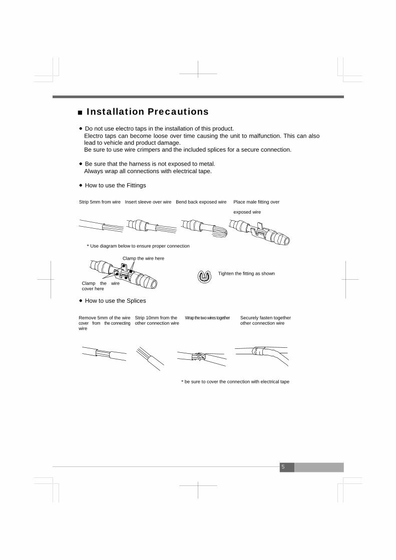
■Installation Precautions ●Do not use electro taps in the installation of this product. Electro taps can become loose over time causing the unit to malfunction. This can also
lead to vehicle and product damage. Be sure to use wire crimpers and the included splices for a secure connection. ●Be sure that the harness is not exposed to metal. Always wrap all connections with electrical tape. ●How to use the Fittings
Strip 5mm from wire Insert sleeve over wire Bend back exposed wire Place male fitting over
exposed wire * Use diagram below to ensure proper connection Tighten the fitting as shown ●How to use the Splices
* be sure to cover the connection with electrical tape
Clamp the wire cover here
Clamp the wire here
Remove 5mm of the wire cover from the connecting wire
Strip 10mm from the other connection wire
Wrap the two wires together Securely fasten together other connection wire

6
■ECU Arrangement Diagram
●Perform installation by referring to the symbols in the corresponding
columns of the tables of applicable models on and after page 13
A
B
C
D
E F
G
H
I
J K
P L
M N
O
A : Lower part of the passenger seat dash side B : Right side of the glove box C : Foot position of the passenger seat D : Inner part of the glove box E : Inner part of the center console F : Under the driver’s seat G : Under the passenger seat H : Near the steering column I : Left side of the meter panel J : Lower part of the driver’s seat dash side K : Left side of the center console L : Engine room M : Before the rear trunk N : Behind after the driver’s seat O : Behind the passenger seat P : Upper inner part of the center console

7
■How to Refer to the ECU Terminal
Arrangement Diagram
This ECU terminal arrangement diagram is viewed from the direction of
the arrow.
The direction of the ECU varies depending upon the vehicle. Perform
the installation work after confirming the connector shape and the
number of pins.
●If any abnormal noise or abnormal smell is sensed during the installation work
of this product, stop the work immediately and contact the distributor or your
nearest A’PEX business office
Continuing the installation under such conditions may cause an electric shock or fire causing damage to electric devices.
Warning !

8
■Installation Diagram Selection Table
●Vehicles not listed below will use Connection Diagram (1) or (2).
TOYOTA Speed Limiter
Name Type Engine Year Notes CUT RETAIN
Celsior UCF2#
1UZ-FE ‘94.10~‘97.6 4 4
UCF1# ‘92.9~‘94.9 3 3
Crown JZS155 2JZ-GE ‘95.8~‘97.6 Excluding
5AT cars 4 4
JZS15# 1JZ-GE ‘96.9~‘99.8 2WD 3 3
Crown Majesta UZS15#
1UZ-FE
‘95.8~‘97.6 2WD 4 4
UZS141 ‘91.10~‘95.7 3 3
Crown Athlete JZS171W 1JZ-GTE ‘99.9~‘01.7 3 3
Crown Estate JZS17#W 1JZ-GTE ‘99.9~‘01.7 3 3
Aristo JZS161 2JZ-GTE ‘97.8~※
3 JZS160 2JZ-GE ‘97.8~‘00.6
Soarer JZZ30 1JZ-GTE ‘96.8~‘01.3 A/T
3 3 UZZ3# 1UZ-FE ‘91.5~‘93.12
MarkII/Chaser/ Cresta Cresta
JZX100
(※1)
1JZ-GTE ‘96.9~‘01.7 A/T 3 3
1JZ-GE
3
For the vehicles above (except Altezza:GXE10 no TRC), turn the SLC OFF when speed limiter is not being cut and not in use. Refer to instruction manual for information.
※1: JZX100: Incompatible for 1JZ-GE, NA, installed after ‘98.8 For MarkⅡ, incompatible up to model year ‘00.9
9
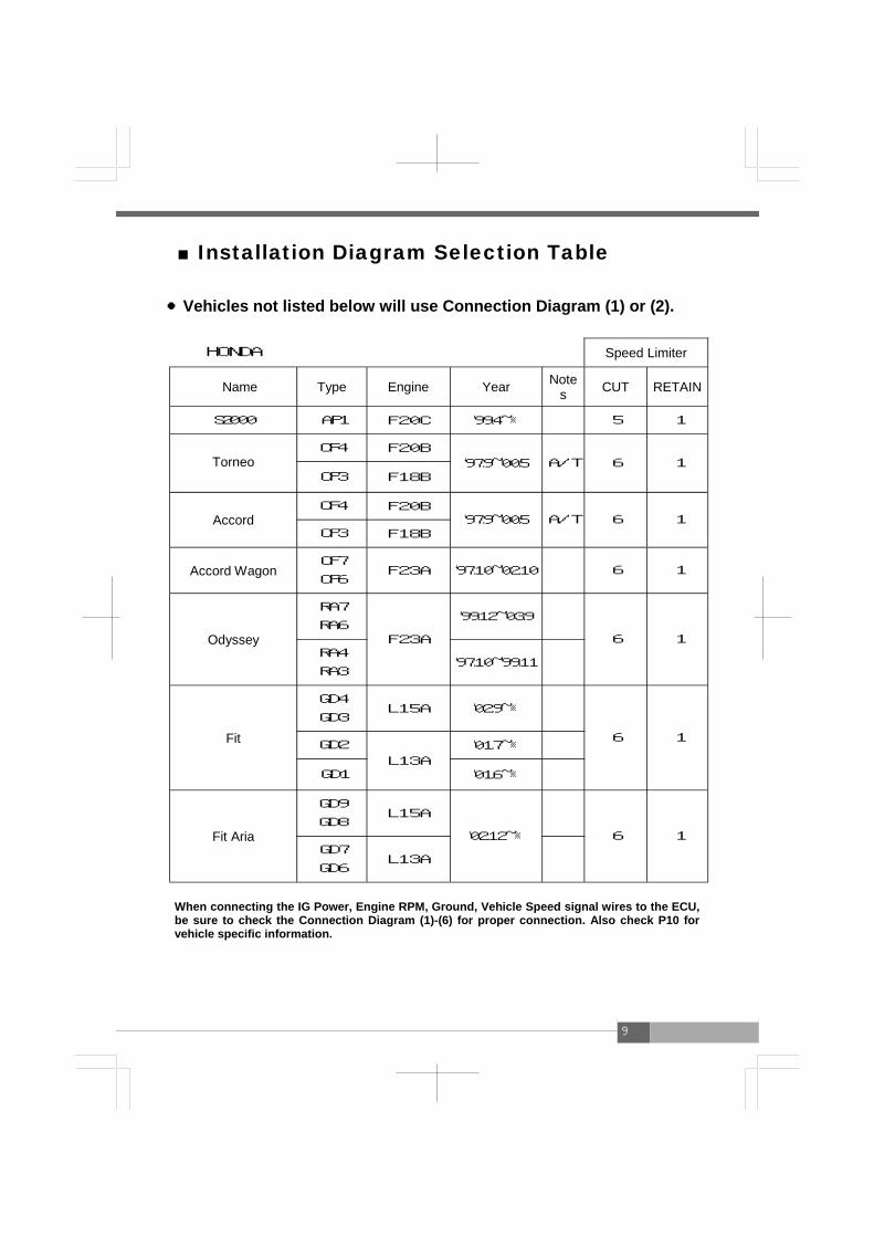
■Installation Diagram Selection Table
●Vehicles not listed below will use Connection Diagram (1) or (2).
HONDA Speed Limiter
Name Type Engine Year Notes CUT RETAIN
S2000 AP1 F20C ‘99.4~※ 5 1
Torneo
CF4 F20B ‘97.9~‘00.5 A/T 6 1
CF3 F18B
Accord CF4 F20B
‘97.9~‘00.5 A/T 6 1 CF3 F18B
Accord Wagon CF7
CF6 F23A ‘97.10~‘02.10 6 1
Odyssey
RA7
RA6 F23A
‘99.12~‘03.9
6 1 RA4
RA3 ‘97.10~‘99.11
Fit
GD4
GD3 L15A ‘02.9~※
6 1 GD2
L13A ‘01.7~※
GD1 ‘01.6~※
Fit Aria
GD9
GD8 L15A
‘02.12~※
6 GD7
GD6 L13A
1
When connecting the IG Power, Engine RPM, Ground, Vehicle Speed signal wires to the ECU, be sure to check the Connection Diagram (1)-(6) for proper connection. Also check P10 for vehicle specific information.
10
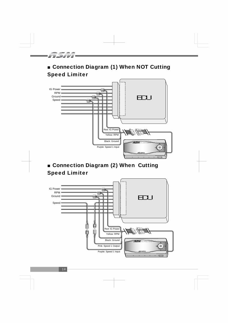
■Connection Diagram (1) When NOT Cutting Speed Limiter
■Connection Diagram (2) When Cutting Speed Limiter
ECU
ECU
Red: IG Power
Yellow: RPM
Black: Ground
Purple: Speed 1 Input
Red: IG Power
Yellow: RPM
Black: Ground
Purple: Speed 1 Input
Pink: Speed 1 Output
IG Power RPM
Ground Speed
IG Power RPM
Ground
Speed

11
■Connection Diagram (3)
■Connection Diagram (4)
ECU
ECU
Red: IG Power
Yellow: RPM
Black: Ground
Blue: Speed 2 Input
Brown: Speed 2 Output
Open
Brown: Speed 2 Output
Blue: Speed 2 Input
Speed 2 Speed 2 GND
Ground RPM
IG Power
Speed 2 Speed 2 GND
Ground RPM
IG Power
Open
Red: IG Power
Yellow: RPM
Black: Ground
Pink: Speed 1 Output
Meter Signal

12
■Connection Diagram (5)
■Connection Diagram (6)
ECU
ECU
RPM Ground Speed
IG Power
Red: IG Power
Yellow: RPM
Black: Ground
Brown: Speed 2 Output
Purple: Speed 1 Input
RPM Ground Speed
IG Power
Meter Signal
Red: IG Power
Yellow: RPM
Black: Ground
Brown: Speed 2 Output
Purple: Speed 1 Input
Open
Pink: Speed 1 Output
13
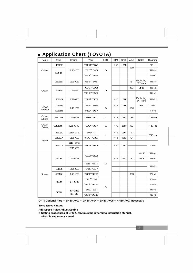
■Application Chart (TOYOTA) Name Type Engine Year ECU OPT SPO ADJ Notes Diagram
Celsior
UCF2#
1UZ-FE
‘94.10~‘97.6
D
※2 174 108
T8-f
UCF1# ‘92.9~‘94.9 T8-a
‘89.11~‘92.8 T5-c
Crown
JZS155 2JZ-GE ‘95.8~‘97.6
D
34 Excluding 5AT cars T8-h
JZS15# 1JZ-GE ‘96.9~‘99.8 30 2WD T8-a
‘95.11~‘96.8 T6-a
JZS143 2JZ-GE ‘91.10~‘95.7 ※2 174 Excluding 5AT cars
T8-b
Crown Majesta
UZS15# 1UZ-FE
‘95.8~‘97.6 D
※2 174 106
2WD T8-f
UZS141 ‘91.10~‘95.7 T7-a
Crown Athlete JZS171W 1JZ-GTE ‘99.9~‘01.7 L ※3 210 36 T10-a
Crown Estate JZS17#W 1JZ-GTE ‘99.9~‘01.7 L ※3 210 36 T10-a
Aristo
JZS161 2JZ-GTE ‘97.8~※ L
※3 190 37 T10-a
JZS160 2JZ-GE ‘97.8~‘00.6 ※1 172
JZS147 2JZ-GTE
‘91.10~‘97.7 C ※4 150
T7-c 2JZ-GE
Soarer
JZZ30 1JZ-GTE ‘96.8~‘01.3
C
M/T T8-g
※2 204 34 A/T T8-c
‘91.5~‘96.7 T8-b
JZZ31 2JZ-GE ‘94.1~‘96.7
UZZ3# 1UZ-FE ‘91.5~‘93.12 108 T7-a
MZ20 7M-GTE ‘89.1~‘91.4
D
T5-a
‘86.1~‘88.12 T2-a
GZ20 1G-GTE
1G-GE
‘89.1~‘91.4 T5-a
‘86.1~‘88.12 T2-a
34
OPT: Optional Part ※1:430-A003 ※2:430-A004 ※3:430-A005 ※4:430-A007 necessary
SPO: Speed Output Adj: Speed Pulse Adjust Setting ※Setting procedures of SPO & ADJ must be reffered to Instruction Munual, which is separately issued

14
Name Type Engine Year ECU OPT SPO ADJ Notes Diagram
Mark II/Chaser/ Cresta
JZX100
(※5)
1JZ-GTE
‘96.9~‘01.7
E
M/T T8-g
※2 197 34 A/T T8-c
1JZ-GE 33 4AT
2WD T8-a
JZX90 1JZ-GTE
‘94.9~‘96.8 M/T
T8-d ※2 186 A/T
‘92.10~‘94.8
1JZ-GE ‘92.10~‘96.8
T6-a JZX81
1JZ-GTE
1JZ-GE ‘90.8~‘92.9
D
GX81 1G-GTE
1G-GE ‘88.8~‘92.9 T5-a
Celica ZZT231 2ZZ-GE ‘99.9~※ L ※2 174 A/T T9-a
OPT: Optional Part ※1:430-A003 ※2:430-A004 ※3:430-A005 ※4:430-A007 necessary
SPO: Speed Output Adj: Speed Pulse Adjust Setting ※Setting procedures of SPO & ADJ must be reffered to Instruction Munual, which is separately issued
※5: JZX 100 : Incompatible for 1JZ-GE,NA, installed after ‘98.7 For Mark Ⅱ,incompatible up to model year ‘00.9

15
Name Type Engine Year ECU Notes Diagram
Supra
JZA80 2JZ-GTE
‘97.8~‘02.8
C
M/T T10-b
‘93.5~‘97.7 T7-b
2JZ-GE ‘93.5~‘97.7
JZA70 1JZ-GTE ‘90.8~‘93.4
D
T6-a
MA70 7M-GTE
‘88.9~‘90.7 T5-a
‘86.2~‘88.8 T2-a
‘88.8 Turbo A T5-a
GA70 1G-GTE
1G-GE
‘88.9~‘93.4
‘86.2~‘88.8 T2-a
Altezza SXE10 3S-GE ‘98.10~※ L M/T T9-b
MR-S ZZW30 1ZZ-FE ‘99.10~※ O Includes Sequential T9-a
MR2
SW20
3S-GTE ‘93.10~‘99.10
M
T5-a
3S-GE ‘97.12~‘99.10 M/T T9-a
‘93.10~‘97.11 T6-a
3S-GTE T5-a
3S-GE
AW11 4A-GZE ‘86.8~‘89.9 T2-a
4A-GE ‘84.6~‘89.9 T1-a
Celica
ZZT231 2ZZ-GE ‘99.9~※
L M/T T9-a
ZZT230 1ZZ-FE
ST205 3S-GTE ‘94.2~‘99.8 T5-a
ST203
ST202
3S-GE ‘97.12~‘99.8 T9-a
‘93.10~‘97.11 T6-a
3S-FE
‘96.6~‘99.8 M/T T4-b
A/T T5-d
‘95.8~‘96.5 M/T T4-a
A/T
T5-a ‘93.10~‘95.7
ST185 3S-GTE ‘89.10~‘93.9
ST182 3S-GE
ST165 3S-GTE ‘85.8~‘89.9
T2-a
ST162 3S-GE
‘89.10~‘93.9
16
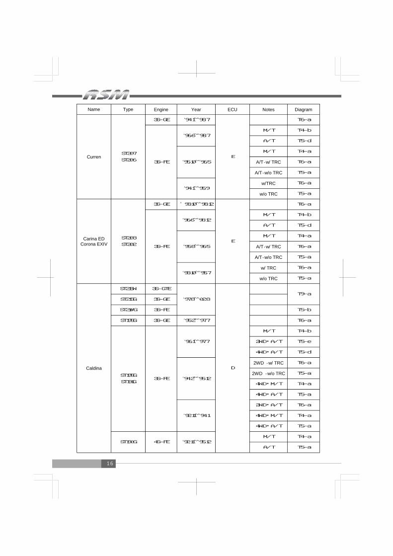
Name Type Engine Year ECU Notes Diagram
Curren ST207
ST206
3S-GE ‘94.1~‘98.7
E
T6-a
3S-FE
‘96.6~‘98.7 M/T T4-b
A/T T5-d
‘95.10~‘96.5
M/T T4-a
A/T・w/ TRC T6-a
A/T・w/o TRC T5-a
‘94.1~‘95.9 w/TRC T6-a
w/o TRC T5-a
Carina ED Corona EXIV
ST203
ST202
3S-GE ‘93.10~‘98.12
E
T6-a
3S-FE
‘96.6~‘98.12 M/T T4-b
A/T T5-d
‘95.8~‘96.5
M/T T4-a
A/T・w/ TRC T6-a
A/T・w/o TRC T5-a
‘93.10~‘95.7 w/ TRC T6-a
w/o TRC T5-a
Caldina
ST215W 3S-GTE
‘97.8~‘02.8
D
ST215G 3S-GE
ST21#G 3S-FE T5-b
ST195G 3S-GE ‘95.2~‘97.7 T6-a
ST195G
ST191G 3S-FE
‘96.1~‘97.7
M/T T4-b
2WD・A/T T5-e
4WD・A/T T5-d
‘94.2~‘95.12
2WD ・w/ TRC T6-a
2WD ・w/o TRC T5-a
4WD・M/T T4-a
4WD・A/T T5-a
‘92.11~‘94.1
2WD・A/T T6-a
4WD・M/T T4-a
4WD・A/T T5-a
ST190G 4S-FE ‘92.11~‘95.12 M/T T4-a
A/T T5-a
T9-a

17
Name Type Engine Year ECU Notes Diagram
Corolla FX
AE101 4A-GE
4A-FE ‘92.5~‘95.4
E
M/T T4-a
A/T T5-a
AE92 4A-GE ‘89.5~‘92.4 T4-a
‘87.5~‘89.4 T1-a
Corolla Sprinter
AE111 4A-GE ‘97.4~‘00.9
E
T5-a
4A-FE ‘95.5~‘97.3
T4-a AE110 5A-FE ‘95.5~‘00.9
AE101 4A-GE
4A-FE ‘91.6~‘95.4
M/T
A/T T5-a
AE92 4A-GE
‘89.5~‘91.5 T4-a
‘87.5~‘89.4 T1-a
Corolla Levin Sprinter Trueno
AE111 4A-GE
E
T5-a
4A-FE T4-a
AE110 5A-FE T4-a
AE101
4A-GZE
‘91.6~‘95.4
T5-a
4A-GE
4A-FE
M/T T4-a
A/T T5-a
AE92
4A-GZE ‘89.5~‘91.5
‘87.5~‘89.4 T2-a
4A-GE ‘89.5~‘91.5 T4-a
‘87.5~‘89.4 T1-a
AE86 4A-GEU ‘83.5~‘87.4 A
Corolla Celes Sprinter Marino AE101
4A-GE
4A-FE ‘92.5~‘95.4 E
M/T T4-a
A/T T5-a
Starlet
EP91 4E-FTE ‘96.1~‘99.7
D T4-a
4E-FE ‘96.1~‘97.12 T3-a
EP82 4E-FTE
‘89.12~‘95.12
E
M/T
‘92.1~‘95.12 A/T T4-a
4E-FE ‘89.12~‘95.12 T3-a
EP71 2E-TE
2E-E ‘86.1~‘89.11 T1-a
‘95.5~‘00.9
18
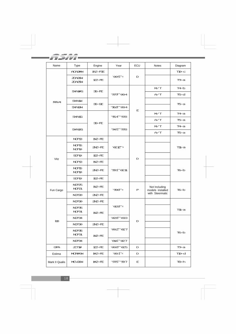
Name Type Engine Year ECU Notes Diagram
RAV4
ACA2#W 1AZ-FSE
‘00.5~※ D
T10-c
ZCA26W
ZCA25W 1ZZ-FE T9-a
SXA1#G 3S-FE ‘97.9~‘00.4
E
M/T T4-b
A/T T5-d
SXA11W 3S-GE
T5-a
SXA10W ‘96.8~‘00.4
SXA11G
3S-FE
‘95.4~‘97.8 M/T T4-a
A/T T5-a
SXA10G ‘94.5~‘97.8 M/T T4-a
A/T T5-a
Vitz
NCP13 1NZ-FE
‘02.12~※
D
T11-a NCP15
NCP10 2NZ-FE
SCP10 1SZ-FE
NCP13 1NZ-FE
‘99.1~‘02.11
T6-b NCP15
NCP10 2NZ-FE
SCP10 1SZ-FE
Fun Cargo NCP25
NCP21 1NZ-FE
‘99.8~※ P Not Including
models installed with Steermatic
T6-b
NCP20 2NZ-FE
bB
NCP30 2NZ-FE
‘02.8~※
D
T11-a NCP35
NCP31 1NZ-FE
NCP34 ‘02.8~‘03.3
NCP30 2NZ-FE
T6-b NCP35
NCP31 1NZ-FE
NCP34 ‘01.6~‘02.7
OPA ZCT1# 1ZZ-FE ‘00.8~‘02.5 D T9-a
Estima MCR#0W 1MZ-FE ‘00.1~※ D T10-d
Mark II Qualis MCV20W 1MZ-FE ‘97.5~‘99.7 E T8-h
‘00.2~‘02.7
19
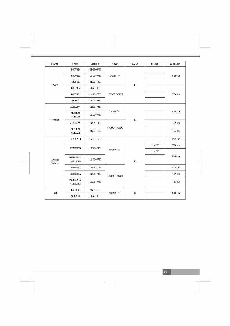
Name Type Engine Year ECU Notes Diagram
Platz
NCP16 2NZ-FE
‘02.8~※
E
T11-a NCP12 1NZ-FE
SCP11 1SZ-FE
NCP16 2NZ-FE
‘99.8~‘02.7
T6-b NCP12 1NZ-FE
SCP11 1SZ-FE
Corolla
ZZE12# 1ZZ-FE
‘02.9~※
D
T11-a NZE124
NZE121 1NZ-FE
ZZE12# 1ZZ-FE
‘00.8~‘02.8
T9-a
NZE124
NZE121 1NZ-FE T6-b
Corolla Fielder
ZZE123G 2ZZ-GE
‘02.9~※
T10-e
ZZE122G 1ZZ-FE M/T T9-a
A/T
T11-a NZE124G
NZE121G 1NZ-FE
ZZE123G 2ZZ-GE
‘00.8~‘02.8
T10-e
ZZE122G 1ZZ-FE T9-a
NZE124G
NZE121G 1NZ-FE T6-b
Ist NCP61 1NZ-FE
‘02.5~※ D
T11-a NCP60 2NZ-FE
D

20
■ECU Diagram (TOYOTA)
10p 18p 14pT1-a T2-a
T3-a
10p 18p 24p
26p 16pT4-a
26p 16p 12p
T4-b 26p 16p 12p T5-a26p 16p 22p
T5-b26p 16p 22p
T5-c26p 16p 22p
T5-d26p 16p 22p
T5-e26p 16p 22p
RPM
Ground Speed IG Power
RPM Speed
Ground IG Power
IG Power Speed Ground
RPM RPM
Ground Speed IG Power
IG Power Speed Ground RPM
RPM
Ground
Speed
IG Power
IG Power
Speed
Ground RPM
RPM
Ground Speed IG Power
IG Power
Speed
RPM Ground Ground
RPM Speed
IG Power

21
T6-a26p 16p 12p 22p
T6-b26p 16p 12p 22p
T7-a T7-b
T8-a34p 22p 16p 28p
T8-b34p 22p 16p 28p
T8-c 34p 22p 16p 28p T8-d34p 22p 16p 28p
T8-e34p 22p 16p 28p
T8-f 34p 22p 16p 28p
IG Power
Speed
RPM Ground Ground RPM
Speed
IG Power
IG Power
RPM
Ground Speed2
Speed2GND RPM
Ground
Speed
IG Power
IG Power Ground Speed2
Speed2GND RPM RPM
Ground
Speed
IG Power
IG Power Ground
RPM Speed2GND
Speed2 IG Power
Speed RPM
Ground
Ground Speed2
Speed2GND RPM Meter Signal
IG Power IG Power Ground Speed2
Speed2GND Meter Signal RPM

22
T8-g34p 22p 16p 28p
T8-h34p 22p 16p 28p
31p 24p 28p 22pT9-a
31p 24p 28p 22pT9-b
T10-a31p 24p 17p 28p 22p
T10-b31p 24p 17p 28p 22p
RPM
IG Power
Speed
Ground Ground
Speed
IG Power
RPM
RPM Ground
Speed IG Power
IG Power
Speed
RPM Ground
Ground Speed2GND
Speed2
RPM IG Power
IG Power Speed Ground RPM

23
T10-d31p 24p 17p 28p 22p
T10-c31p 24p 17p 28p 22p
T10-e31p 24p 17p 28p 22p
34p 35p 31p35pT11-a
RPM
Ground Speed
IG Power
IG Power Speed Ground RPM
Ground IG Power RPM Speed
Ground IG Power
RPM
Speed

24
■Application Chart (NISSAN) Name Type Engine Year ECU Notes Diagram
President G50 VH45DE ‘90.10~‘02.12 A N4-a
Infiniti Q45 G50 VH45DE ‘89.11~‘97.9 A N4-a
Cima Ⅲ FGY33 VH41DE
‘96.6~‘98.9 A N6-a
FHY33 VQ30DET N5-a
Cima Ⅱ FGY32 VH41DE ‘91.8~‘96.5
A
N4-a FPY32 VG30DET ‘93.9~‘96.5
Cima Ⅰ FPY31 VG30DET
VG30DE
‘89.8~‘91.7 A
N4-a
‘88.1~‘89.7 N2-a
Fairlady Z
Z32 VG30DETT
VG30DE ‘89.7~‘00.8 C N4-a
Z31
VG30DET
VG30DE
RB20DET
‘86.10~‘89.6 A N1-a
Leopard
Y33 VQ30DET
VQ30DE ‘96.3~‘99.6
A
N5-a
UF31 VG30DET
VG30DE ‘88.8~‘92.5 N4-a
GF31 VG20DET N2-a
Leopard J Feri JGBY32 VH41DE
‘92.6~‘96.2 A
N4-a JPY32 VG30DE
Cedric/Gloria
Y34
VQ30DET ‘99.6~‘04.10
D
N8-d
VQ30DD
VQ25DD N9-a
Y33 VQ30DET
VQ30DE ‘95.6~‘99.5
A
N5-a
Y32 VG30DET
VG30DE ‘91.6~‘95.5
N4-a
Y31 VG20DET
VG20E ‘89.6~‘91.5
Cefiro Wagon W#A32
VQ30DE ‘97.1~‘99.7
E
N6-a VQ25DE
VQ20DE ‘97.1~‘00.8
Teranno YD21 VG30E ‘89.10~‘95.8 F N3-a

25
Name Type Engine Year ECU Notes Diagram
Cefiro
A33 VQ25DD
‘98.12~‘00.12
E
N9-a
VQ20DE N8-a
A32
VQ30DE
VQ25DE
‘97.1~‘98.11
N6-a
VQ20DE M/T N4-a
A/T N6-a
VQ30DE
VQ25DE
VQ20DE
‘94.8~‘96.12
N4-a
A31
RB20DET
RB20DE
RB25DE
‘88.9~‘94.7 A Excluding 5AT cars
Laurel
C35
RB25DET
RB25DE
RB20DE
‘97.6~‘02.12
A
N6-a
C34
RB25DET ‘94.1~‘97.5
N4-a
RB25DE
RB20DE ‘93.1~‘97.5
C33 RB20DET
RB20DE ‘89.1~‘92.12
Skyline
R34 RB26DETT ‘99.1~‘02.8
A
N4-a
RB25DET ‘98.5~‘01.5 N6-a
R33
RB26DETT ‘95.1~‘98.12
N4-a
RB25DET
RB25DE ‘93.8~‘98.4 Excluding
5AT cars
R32
RB26DETT ‘89.8~‘94.12
RB25DE ‘91.8~‘93.7 Excluding 5AT cars
RB20DET
RB20DE ‘89.5~‘93.7
R31 RB20ET
RB20E ‘87.8~‘89.4 N1-a
Stagia W#C34 RB25DET
RB25DE ‘96.8~‘01.9 A N6-a
Stagia Autech Ver.260RS WGNC34 RB26DETT ‘97.10~‘01.9 A N4-a
Excluding 5AT cars
26
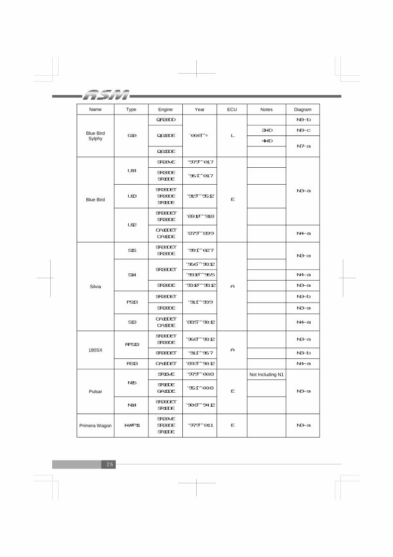
Name Type Engine Year ECU Notes Diagram
Blue Bird Sylphy G10
QR20DD
‘00.8~※ L
N8-b
QG18DE 2WD N8-c
4WD N7-a
QG15DE
Blue Bird
U14
SR20VE ‘97.9~‘01.7
E
N3-a
SR20DE
SR18DE ‘96.1~‘01.7
U13
SR20DET
SR20DE
SR18DE
‘91.9~‘95.12
U12
SR20DET
SR20DE ‘89.10~‘91.8
CA18DET
CA18DE ‘87.9~‘89.9 N4-a
Silvia
S15 SR20DET
SR20DE ‘99.1~‘02.7
A
N3-a
S14 SR20DET
‘96.6~‘98.12
‘93.10~‘96.5 N4-a
SR20DE ‘93.10~‘98.12 N3-a
PS13 SR20DET
‘91.1~‘93.9 N3-b
SR20DE N3-a
S13 CA18DET
CA18DE ‘88.5~‘90.12 N4-a
180SX RPS13
SR20DET
SR20DE ‘96.8~‘98.12
A
N3-a
SR20DET ‘91.1~‘96.7 N3-b
RS13 CA18DET ‘89.3~‘90.12 N4-a
Pulsar N15
SR16VE ‘97.9~‘00.8
E
Not Including N1
N3-a
SR18DE
GA16DE ‘95.1~‘00.8
N14 SR20DET
SR18DE ‘90.8~‘94.12
Primera Wagon W#P11
SR20VE
SR20DE
SR18DE
‘97.9~‘01.1 E N3-a

27
Name Type Engine Year ECU Notes Diagram
Primera
P11
SR20VE ‘97.9~‘01.1
E
N3-a
SR20DE
SR18DE ‘95.9~‘01.1
P10 SR20DE ‘90.2~‘95.8
SR18DE ‘92.9~‘95.8
Wing Road Y11
SR20VE ‘99.5~‘01.9
E
N3-a
QG18DE
QG15DE ‘99.5~※ N7-a
Avenier
W11 SR20DET
SR20DE ‘98.8~‘00.4
E
N3-a
W10
SR20DET ‘95.8~‘98.7
SR20DE ‘90.5~‘98.7
SR18DE ‘93.1~‘98.7
Sunny
B15 SR16VE ‘98.10~‘99.8
E
N3-a B14 SR18DE
‘94.1~‘98.9
B13 ‘90.1~‘93.12
NX Coupe B13 SR18DE ‘90.1~‘93.12 E N3-a
March K11 CG13DE
‘92.1~‘02.2 E
Including CGA3DE N3-a
CG10DE
Cube Z10 CG13DE ‘98.2~‘02.9 C Including CGA3DE N3-a

28
■ECU Diagram (NISSAN) N1-a
15p 12p 20p 16p
N3-a16p 14p 16p 18p
N3-b16p 14p 16p 18p
N4-a16p 20p 20p 20p
N2-a16p 12p 20p 16p
N5-a9p 19p 33p9p 18p�
N6-a12p 12p 19p 24p 37p
N7-a6p 25p22p 6p22p
N8-a8p 38p 19p 38p 8p
N8-b8p 38p 19p 38p 8p
RPM
Speed
Ground
IG Power
RPM
Speed IG Power
Ground
Ground
IG Power
Speed RPM RPM Speed
IG Power
Ground
Ground
IG Power
Speed RPM RPM Speed Ground
IG Power
IG Power Ground Speed RPM RPM Ground IG Power
Speed
Speed
IG Power Ground
RPM RPM
Ground Speed IG Power

29
N8-c8p 38p 19p 38p 8p
N9-a
12p 42p 42p 42p 12p
N8-d8p 38p 19p 38p 8p
IG Power Speed Ground
RPM RPM
Ground Speed IG Power
IG Power Ground Speed
RPM
30
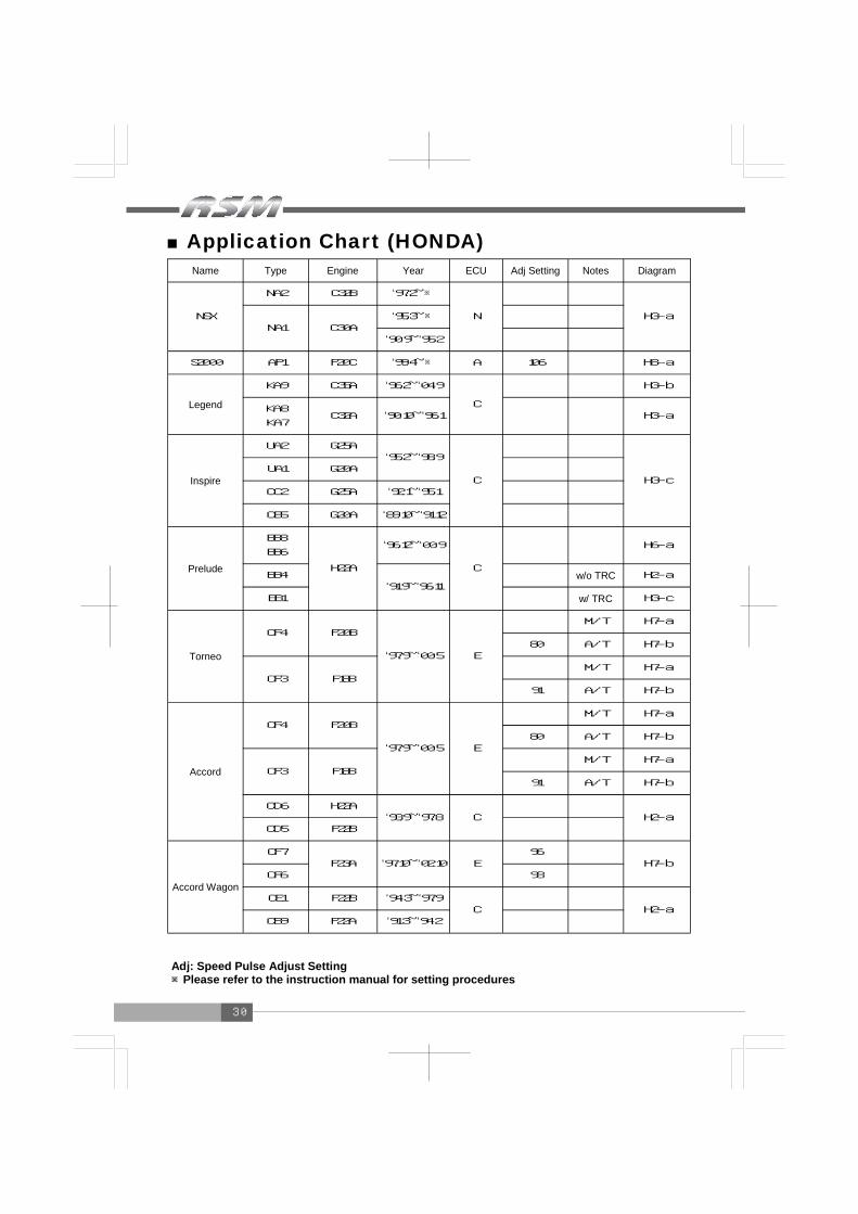
■Application Chart (HONDA) Name Type Engine Year ECU Adj Setting Notes Diagram
NSX
NA2 C32B ‘97.2~※
N
H3-a NA1 C30A
‘95.3~※
‘90.9~‘95.2
S2000 AP1 F20C ‘99.4~※ A 106 H8-a
Legend
KA9 C35A ‘96.2~‘04.9
C
H3-b
KA8
KA7 C32A ‘90.10~‘96.1 H3-a
Inspire
UA2 G25A ‘95.2~‘98.9
C
H3-c UA1 G20A
CC2 G25A ‘92.1~‘95.1
CB5 G20A ‘89.10~‘91.12
Prelude
BB8
BB6
H22A
‘96.12~‘00.9
C
H6-a
BB4 ‘91.9~‘96.11
w/o TRC H2-a
BB1 w/ TRC H3-c
Torneo
CF4 F20B
‘97.9~‘00.5 E
M/T H7-a
80 A/T H7-b
CF3 F18B M/T H7-a
91 A/T H7-b
Accord
CF4 F20B
‘97.9~‘00.5 E
M/T H7-a
80 A/T H7-b
CF3 F18B M/T H7-a
91 A/T H7-b
CD6 H22A ‘93.9~‘97.8 C
H2-a
CD5 F22B
Accord Wagon
CF7 F23A ‘97.10~‘02.10 E
96 H7-b
CF6 93
CE1 F22B ‘94.3~‘97.9 C
CB9 F22A ‘91.3~‘94.2 H2-a
Adj: Speed Pulse Adjust Setting ※Please refer to the instruction manual for setting procedures

31
Name Type Engine Year ECU Adj Setting Notes Diagram
Integra (including the
’98 specification)
DC5 K20A ‘01.7~※ D M/T H9-a
DC2
DB8 B18C
‘95.9~‘01.6
A
M/T H6-a
A/T H3-c
‘93.5~‘95.8 M/T H2-a
A/T H3-a
DA6 B16A ‘89.4~‘93.5 C H1-a
Civic
EP3 K20A ‘01.12~※ D H9-a
EK9 B16B
‘00.8~‘00.9
A
H8-b
‘98.9~‘00.7 H7-a
‘97.6~‘98.8 H6-a
EK4 B16A ‘98.9~‘00.7 H7-a
‘95.9~‘98.8 H6-a
EK3 D15B ‘98.9~‘00.7 w/ VTEC H7-a
‘95.9~‘98.8 H6-a
EG6 B16A
‘91.9~‘95.8
H2-a EG4 D15B Excluding
carburetor cars
EF9 B16A ‘89.9~‘91.8 C H1-a
Odyssey
RA7
F23A
‘99.12~‘03.9 E 86
RA6 89
RA4
RA3 ‘97.10~‘99.11
C
87
RA2
RA1 F22B ‘94.10~‘97.9 H2-a
H7-b
Adj: Speed Pulse Adjust Setting ※Please refer to the instruction manual for setting procedures
32
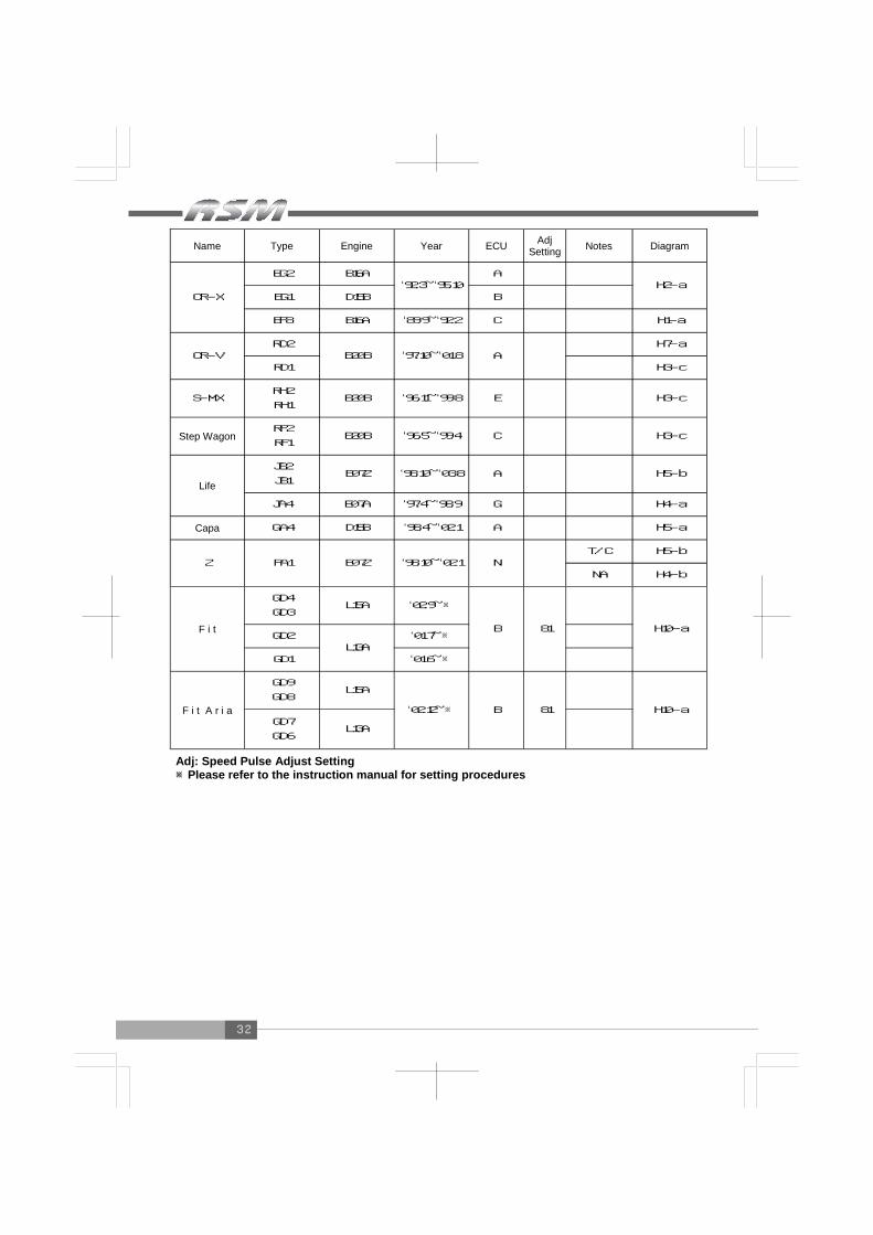
Name Type Engine Year ECU Notes Diagram
CR-X
EG2 B16A ‘92.3~‘95.10
A H2-a
EG1 D15B B
EF8 B16A ‘89.9~‘92.2 C H1-a
CR-V RD2
B20B ‘97.10~‘01.8 A H7-a
RD1 H3-c
S-MX RH2
RH1 B20B ‘96.11~‘99.8 E H3-c
Step Wagon RF2
RF1 B20B ‘96.5~‘99.4 C H3-c
Life
JB2
JB1 E07Z ‘98.10~‘03.8 A H5-b
JA4 E07A ‘97.4~‘98.9 G H4-a
Capa GA4 D15B ‘98.4~‘02.1 A H5-a
Z PA1 E07Z ‘98.10~‘02.1 N T/C H5-b
NA H4-b
F i t
GD4
GD3 L15A ‘02.9~※
B
H10-a GD2
L13A ‘01.7~※
GD1 ‘01.6~※
F i t A r i a
GD9
GD8 L15A
‘02.12~※ B
GD7
GD6 L13A
H10-a
Adj Setting
81
81
Adj: Speed Pulse Adjust Setting ※Please refer to the instruction manual for setting procedures
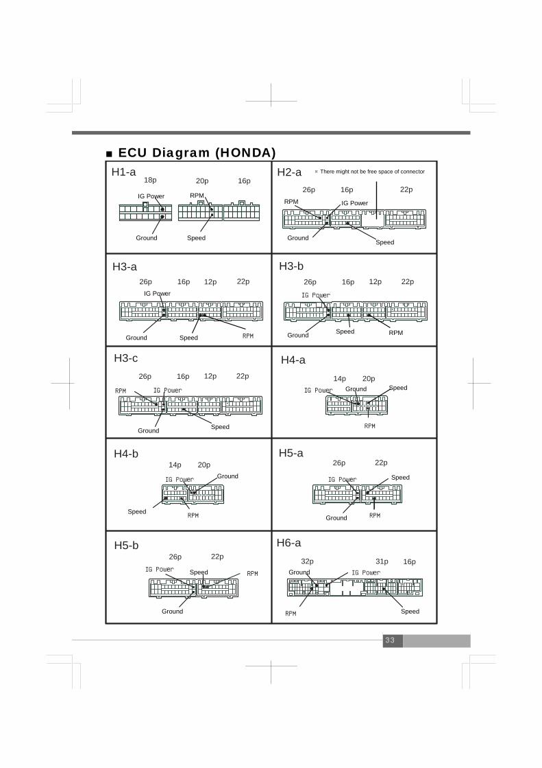
33
H1-a18p 20p 16p
H3-b
26p 16p 22p
H3-c
26p 16p 22p 26p 16p 12p 22p
H4-b
20p14p
H4-a
12p
26p 16p 12p 22p
H3-a
20p14p
H2-a
H5-a26p 22p
H5-b26p 22p
H6-a31p 16p32p
■ECU Diagram (HONDA)
RPM
Speed Ground
IG Power IG Power
Ground Speed
Ground
IG Power
Speed RPM RPM Ground Speed
IG Power
IG Power RPM
Ground Speed
Speed
RPM
IG Power Ground
Ground IG Power
Speed RPM RPM Ground
IG Power Speed
Speed RPM IG Power
Ground
Ground IG Power
RPM Speed
RPM
※There might not be free space of connector

34
H7-a32p 25p 31p 16p
H7-b32p 25p 31p 16p
H8-a32p 25p 31p 16p
H8-b32p 25p 31p 16p
H9-a31p 24p 31p
H10-a 22p31p 31p24p
IG Power
Ground
RPM
Speed Speed Ground
IG Power
RPM
Meter Signal
RPM
Speed IG Power
Ground
IG Power
Ground
RPM
Speed
IG Power Ground Speed
RPM
IG Power Ground
RPM Meter Signal Speed
35
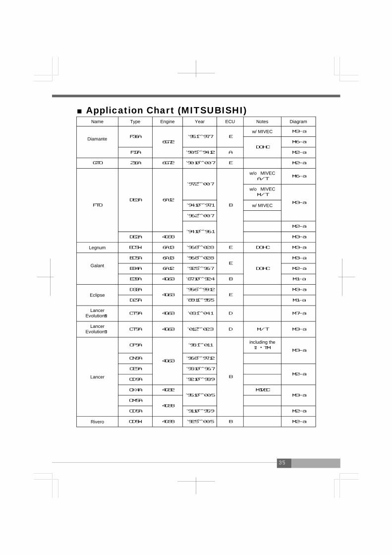
■Application Chart (MITSUBISHI) Name Type Engine Year ECU Notes Diagram
Diamante
F36A 6G72
‘95.1~‘97.7 E w/ MIVEC M3-a
DOHC M6-a
F17A ‘90.5~‘94.12 A M2-a
GTO Z16A 6G72 ‘90.10~‘00.7 E M2-a
FTO DE3A 6A12
‘97.2~‘00.7
B
w/o MIVEC A/T
M6-a
w/o MIVECM/T
M3-a ‘94.10~‘97.1 w/ MIVEC
‘96.2~‘00.7
‘94.10~‘96.1 M2-a
DE2A 4G93 M3-a
Legnum EC5W 6A13 ‘96.8~‘02.8 E DOHC M3-a
Galant
EC5A 6A13 ‘96.8~‘02.8 E
DOHC
M3-a
E84A 6A12 ‘92.5~‘96.7 M2-a
E39A 4G63 ‘87.10~‘92.4 B M1-a
Eclipse D32A
4G63 ‘95.6~‘99.12
E M3-a
D27A ‘89.11~‘95.5 M1-a
Lancer EvolutionⅧ CT9A 4G63 ‘03.1~‘04.1 D M7-a
Lancer EvolutionⅦ CT9A 4G63 ‘01.2~‘02.3 D M/T M3-a
Lancer
CP9A
4G63
‘98.1~‘01.1
B
including the Ⅵ・TM
M3-a
CN9A ‘96.8~‘97.12
CE9A ‘93.10~‘96.7 M2-a
CD9A ‘92.10~‘93.9
CK4A 4G92 ‘95.10~‘00.5
MIVEC M3-a
CM5A 4G93
CD5A ‘91.10~‘95.9 M2-a
Rivero CD5W 4G93 ‘92.5~‘00.5 B M2-a
36
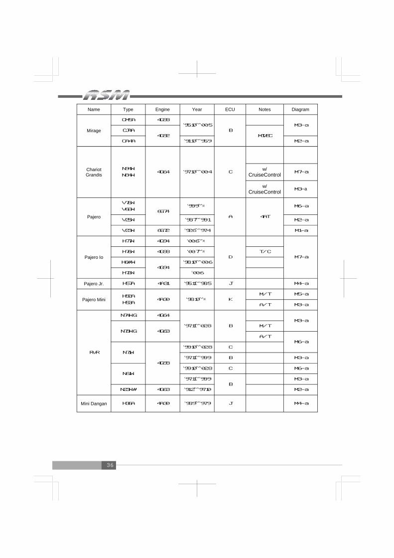
Name Type Engine Year ECU Notes Diagram
Mirage
CM5A 4G93 ‘95.10~‘00.5
B
CJ4A 4G92 MIVEC
CA4A ‘91.10~‘95.9 M2-a
Chariot Grandis
N94W
N84W 4G64 ‘97.10~‘00.4 C
w/ CruiseControl M7-a
w/ CruiseControl M3-a
Pajero
V78W
V68W 6G74 ‘99.9~※
A 4AT
M6-a
V25W ‘93.7~‘99.1 M2-a
V23W 6G72 ‘92.6~‘97.4 M1-a
Pajero Io
H77W 4G94 ‘00.6~※
D
M7-a H76W 4G93 ‘00.7~※ T/C
H6#W 4G94
‘98.10~‘00.6
H72W ‘00.6
Pajero Jr. H57A 4A31 ‘95.11~‘98.5 J M4-a
Pajero Mini H58A
H53A 4A30 ‘98.10~※ K
M/T M5-a
A/T M3-a
RVR
N74WG 4G64
‘97.11~‘02.8 B
M3-a
N73WG 4G63 M/T
A/T M6-a
N71W
4G93
‘99.10~‘02.8 C
‘97.11~‘99.9 B M3-a
N61W ‘99.10~‘02.8 C M6-a
‘97.11~‘99.9 B
M3-a
N23W# 4G63 ‘91.2~‘97.10 M2-a
Mini Dangan H36A 4A30 ‘93.9~‘97.9 J M4-a
M3-a

37
■ECU Diagram (MITSUBISHI)
M2-a26p 16p 22p
M3-a26p 16p 12p 22p
M4-a26p 16p
M1-a10p 18p 24p
M6-a35p 26p 28p 30p
M7-a35p 28p 30p
M5-a26p 22p
Ground IG Power
RPM
Speed Speed
RPM
IG Power Ground
Ground IG Power RPM Speed Speed
RPM IG Power Ground
IG Power
Ground RPM
Speed Speed Ground IG Power RPM
RPM Ground IG Power Speed

38
■Application Chart (MAZDA) Name Type Engine Year ECU Notes Diagram
Eunos Cosmo
JC3S 13B-REW
‘94.3~‘95.8
C
B◎
Z3-a JC3SE ‘90.3~‘94.2
JCES ‘94.3~‘95.8
JCESE ‘90.3~‘94.2
RX-7
FD3S 13B-REW ‘95.12~‘02.8
A Z4-a
‘91.12~‘95.11 Z3-b
FC3S 13B ‘88.9~‘91.11 C
H◎ Only w/Cruise Control
Z2-a
‘85.9~‘88.8 Z1-a
Roadster
NB8C
BP-VE(RS) ‘00.7~※
C
Z9-a
BP-ZE(RS)
‘98.1~‘00.6 Z2-c
NB6C B6-ZE(RS) ‘02.6~※ Z9-a
‘98.1~‘02.5 Z2-c
NA8C BP-ZE ‘95.8~‘97.12 Z6-a
‘93.8~‘95.7 Z5-a
Familia
BJ5P
ZL-DE ‘98.6~‘03.6
D
4WD・M/T Z2-d
4WD・A/T Z3-d
2WD Z8-a
ZL-VE ‘98.6~‘99.7 M/T Z2-c
‘98.6~‘01.11 A/T Z3-c
BJ3P B3-ME ‘98.6~‘02.8 M/T Z2-c
A/T Z3-c
BG8Z BP-ZET ‘89.8~‘94.3 E Z5-b
Familia S Wagon
BJFW FS-ZE ‘99.8~‘03.9 D
4WD・M/T Z2-d
4WD・A/T Z3-d
2WD Z3-e
20B-REW
◎Cruise Control Unit Location

39
Name Type Engine Year ECU Notes Diagram
Demio
DW5W B5E ‘99.12~‘02.7
I
Z8-a
B5-ME ‘96.8~‘99.11 Z2-b
DW3W B3E ‘99.12~‘02.7 Z8-a
B3-ME ‘96.8~‘99.11 Z2-b
AZ Wagon MD21S K6A T/C
‘98.10~‘00.11 L
Z7-a MD11S F6A T/C
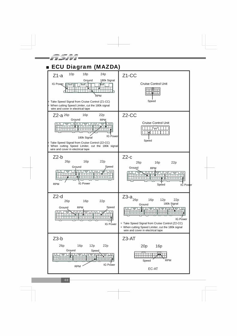
40
■ECU Diagram (MAZDA) Z1-CC
Z2-CC
16p20p
EC-AT
Z3-AT
Z3-a26p 16p 12p 22p
10p 18p 24pZ1-a
Z2-a 26p 16p 22p
Z3-b26p 16p 12p 22p
Z2-b26p 16p 22p
Z2-c26p 16p 22p
Z2-d26p 16p 22p
IG Power Ground 180k Signal
RPM
※Take Speed Signal from Cruise Control (Z1-CC) ※When cutting Speed Limiter, cut the 180k signal wire and cover in electrical tape
Speed
Cruise Control Unit
Ground RPM
180k Signal IG Power
※Take Speed Signal from Cruise Control (Z2-CC) ※When cutting Speed Limiter, cut the 180k signal
wire and cover in electrical tape
Cruise Control Unit
Speed
Ground
RPM IG Power
Speed Ground RPM
Speed IG Power
IG Power
Speed RPM Ground Ground 180k Signal
IG Power ※Take Speed Signal from Cruise Control (Z2-CC) ※When cutting Speed Limiter, cut the 180k signal wire and cover in electrical tape
Ground
RPM
Speed
IG Power Speed RPM
41
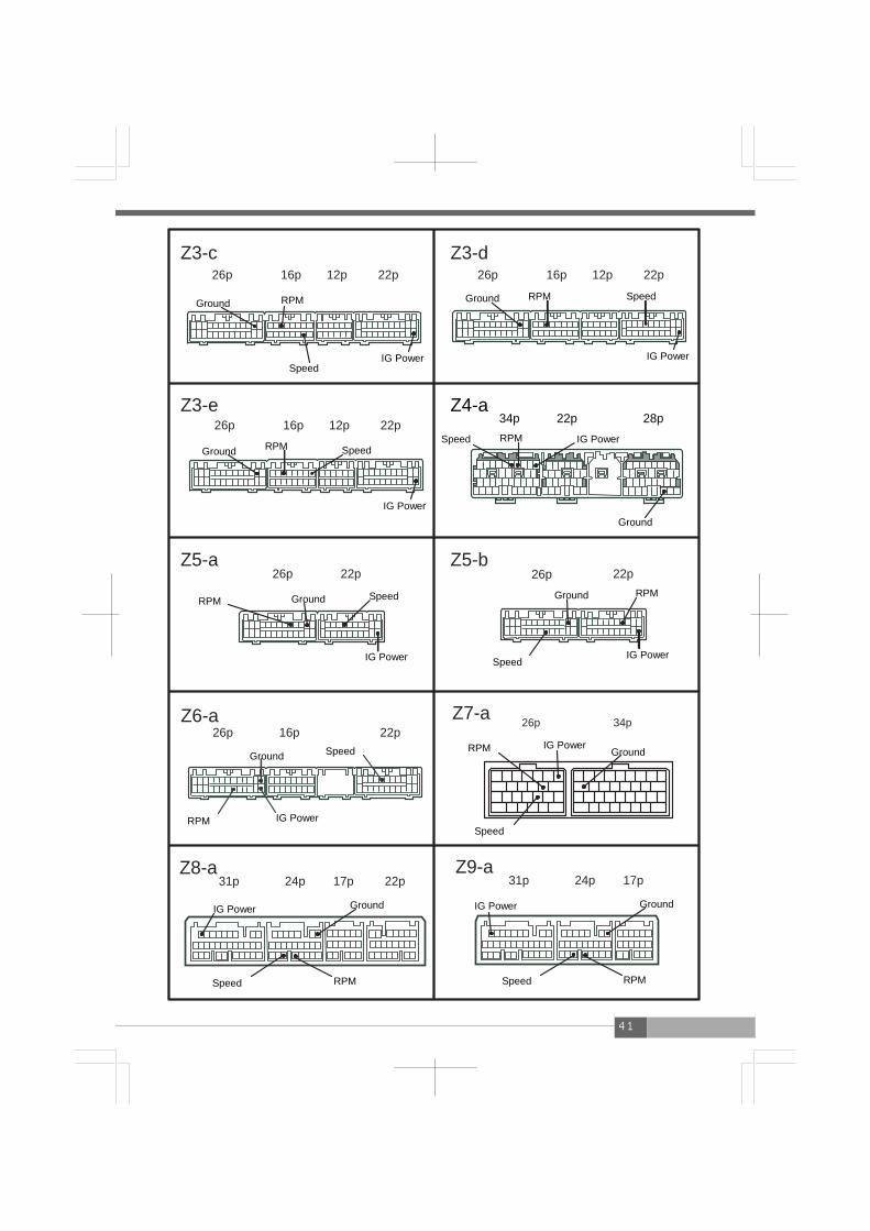
Z7-a 26p 34pZ6-a26p 16p 22p
Z4-a34p 22p 28p
Z5-b22p
Z5-a26p 22p
Z3-e26p 16p 12p 22p
Z3-d26p 16p 12p 22p
Z3-c26p 16p 12p 22p
26p
Z8-a31p 24p 17p 22p
Z9-a31p 24p 17p
RPM Ground
Speed IG Power IG Power
Speed RPM Ground
Ground RPM Speed
IG Power
IG Power RPM Speed
Ground
Ground RPM Speed
IG Power IG Power Speed
Ground RPM
RPM IG Power
Ground Speed
Speed
RPM IG Power Ground
IG Power Ground
Speed RPM RPM Speed
IG Power Ground
42
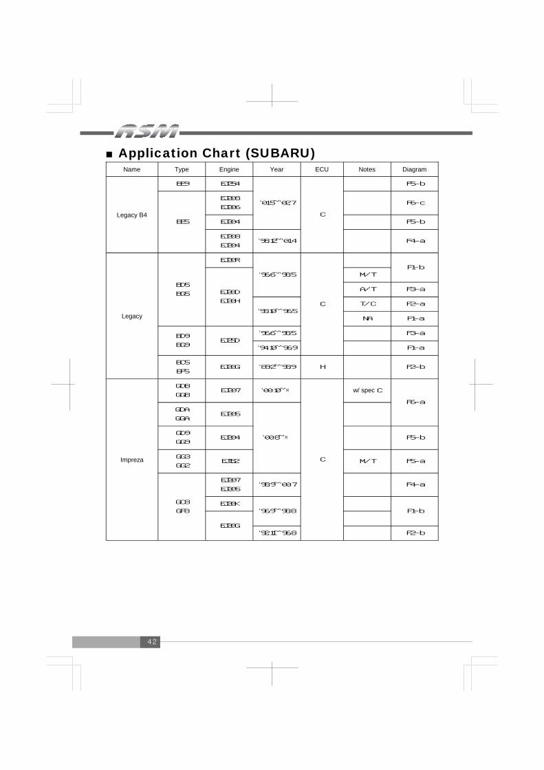
■Application Chart (SUBARU) Name Type Engine Year ECU Notes Diagram
Legacy B4
BE9 EJ254
‘01.5~‘02.7
C
F5-b
BE5
EJ208
EJ206 F6-c
EJ204 F5-b
EJ208
EJ204 ‘98.12~‘01.4 F4-a
Legacy
BD5
BG5
EJ20R
‘96.6~‘98.5
C
F1-b
EJ20D
EJ20H
M/T
A/T F3-a
‘93.10~‘96.5 T/C F2-a
NA F1-a
BD9
BG9 EJ25D
‘96.6~‘98.5 F3-a
‘94.10~‘96.9 F1-a
BC5
BF5 EJ20G ‘89.2~‘93.9 H F2-b
Impreza
GDB
GGB EJ207 ‘00.10~※
C
w/ spec C
F6-a GDA
GGA EJ205
‘00.8~※
GD9
GG9 EJ204 F5-b
GG3
GG2 EJ152 M/T F5-a
GC8
GF8
EJ207
EJ205 ‘98.9~‘00.7 F4-a
EJ20K ‘96.9~‘98.8
F1-b
EJ20G
‘92.11~‘96.8 F2-b
43
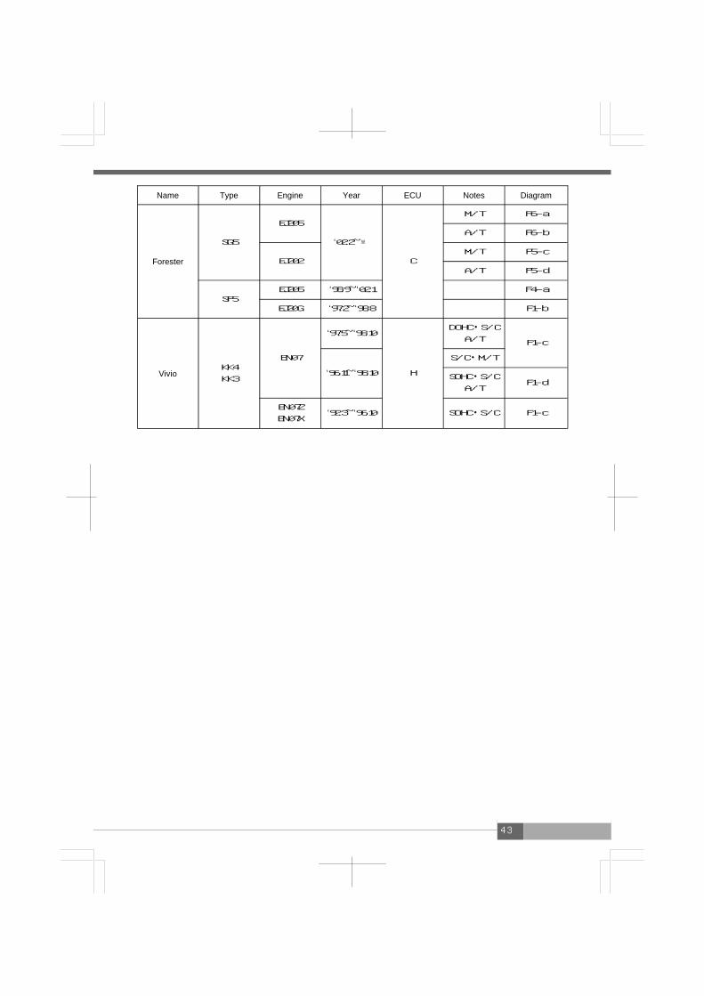
Name Type Engine Year ECU Notes Diagram
Forester
SG5
EJ205
‘02.2~※
C
M/T F6-a
A/T F6-b
EJ202 M/T F5-c
A/T F5-d
SF5 EJ205 ‘98.9~‘02.1 F4-a
EJ20G ‘97.2~‘98.8 F1-b
Vivio KK4
KK3
EN07
‘97.5~‘98.10
H
DOHC・S/C
A/T F1-c
‘96.11~‘98.10
S/C・M/T
SOHC・S/C
A/T F1-d
EN07Z
EN07X ‘92.3~‘96.10 SOHC・S/C F1-c

44
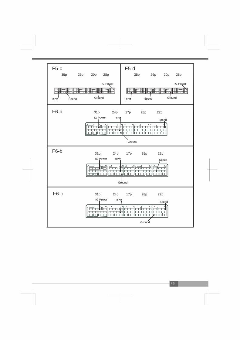
■ECU Diagram (SUBARU)
F3-a9p 19p 33p9p 18p�
F1-b26p 16p 22p
F2-a26p 16p 12p 22p
F1-a26p 16p 22p
F2-b26p 16p 12p 22p
F1-c26p 16p 22p
F1-d26p 16p 22p
F5-a26p 28p20p35p
F5-b26p 28p20p35p
32p 32p 32p
F4-a
IG Power
Ground
RPM
Speed Speed
RPM Ground
IG Power
IG Power Ground
RPM
Speed
Speed
Ground
IG Power RPM
RPM
Speed
Ground IG Power RPM Speed Ground IG Power
IG Power
Ground Speed RPM
RPM Ground
Speed
IG Power
IG Power RPM Speed
Ground Ground Speed
RPM
IG Power
45
F5-c26p 28p20p35p
F6-a 31p 24p 17p 28p 22p
31p 24p 17p 28p 22pF6-b
F5-d26p 28p20p35p
F6-c 31p 24p 17p 28p 22p
IG Power
Ground RPM Speed Speed RPM Ground
IG Power
IG Power RPM
Ground
Speed
Speed RPM
Ground
IG Power
IG Power RPM
Ground
Speed

46
■Application Chart (SUZUKI) Name Type Engine Year ECU Notes Diagram
Alto Works
HA22S K6A T/C ‘98.10~‘00.12 L
w/ VVT S8-a
S6-a
HA12S F6A T/C
HA21S
HB21S K6A T/C
‘94.11~‘98.9 B
S3-a
HA11S
HB11S F6A T/C M/T S2-a
Cappucino EA21R K6A ‘95.5~‘98.6 K M/T S5-a
EA11R F6A ‘91.11~‘95.10 B S1-a
Wagon R
MC21S K6A T/C ‘98.10~‘00.11 L
S6-a
MC11S F6A T/C
CT51S
CV51S K6A T/C ‘97.4~‘98.9
B
S5-a
CT21S
CV21S F6A T/C
‘95.10~‘98.5 A/T S4-a
‘95.10~‘97.10 M/T
S2-a
‘93.9~‘95.9 S1-a
Wagon R Plus MA63S K10A T/C ‘99.5~‘00.11 B S7-a
Wagon R Wide
MA61S
MB61S K10A ‘97.2~‘99.12 B S5-a
Kei HN21S K6A T/C
‘98.10~‘01.3 L
S6-a HN11S F6A T/C
Jimmy
JB23W K6A T/C
‘98.10~※ L S6-a
JA22W ‘95.11~‘98.9 B M/T
S3-a
JA12W F6A T/C S2-a

47
■ECU Diagram (SUZUKI) S1-a
12p 22pS2-a 26p 16p
S6-a26p 34p
S3-a26p 22p
S4-a 26p 16p 12p
S5-a26p 16p 22p
S7-a31p 24p 17p
S8-a26p35p 20p 28p
RPM IG Power Ground
Speed Speed
Ground IG Power RPM
RPM Ground IG
Speed
Speed RPM Ground IG Power
IG Power
Speed
Ground RPM RPM
Speed
IG Power Ground
Ground IG Power Speed
RPM
RPM Speed
IG Power
Ground

48
■Application Chart (DAIHATSU) Name Type Engine Year ECU Notes Diagram
Mira Gino
L710S
L700S EF-DET ‘99.3~※ D D2-a
Mira L710S
L700S EF-DET ‘98.10~‘00.9 D D2-a
Mira TR-XX
L512S
L502S JB-JL ‘94.9~‘98.9
D
D1-a
L500S EF-JL ‘94.9~‘95.9
Move
L900S EF-DET
‘01.10~‘02.9
D
D3-a L910S
L902S JB-DET
L900S EF-DET
‘00.10~‘01.9
D2-a L910S ‘98.10~‘01.9
L902S JB-DET
L602S JB-JL ‘95.8~‘98.9 D1-a
YRV M211G
M201G
K3-VET
K3-VE ‘00.8~※ D D3-a
Name Type Engine Year ECU Notes Diagram
Big Horn UBS25 6VD1 ‘91.12~‘98.1 E I1-a
■Application Chart (ISUZU)
49
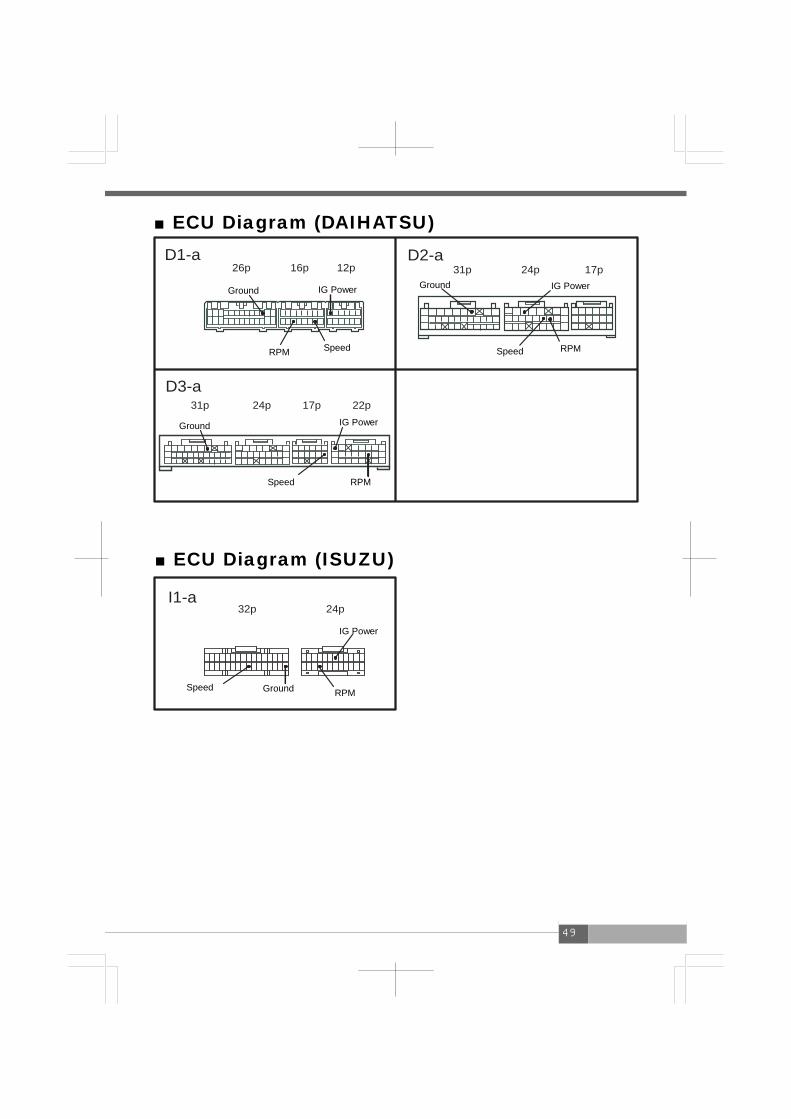
■ECU Diagram (DAIHATSU)
I1-a32p 24p
D2-a31p 24p 17p
D1-a26p 16p 12p
31p 24p 17p 22pD3-a
■ECU Diagram (ISUZU)
Ground
RPM Speed
IG Power IG Power Ground
Speed RPM
RPM Speed
IG Power Ground
Ground Speed RPM
IG Power

50
●Memo

51
●Memo

52
Notes 1. The contents of this document are subject to change without prior notice
2. The contents of this document have been prepared with extreme care. However, if you find, error, or other fault, please inform us of it
3. A part or all of this document may not be reproduced in any form without prior written permission, and also may not used without the prior written permission of
APEXERA CO., LTD. under the copyright except for private use.
・The company names and product names described in this document are the registered
trademarks or brands of the respective companies
・The names, addresses and telephone numbers mentioned as where to contact
are as of Feb. 1, 2005. Note that this information is subject to change
No, Date of issue Part No. of instruction manual Edition Change of description
1 Feb 7,2001 7407ー0210ー00 First Edition
2 Apr 9,2001 7407-0210ー01 Ver.2
3 Aug 19,2002 7407-0250-00 Ver.3
4 Dec 1,2003 7407-0250-01 Ver.4
5 Jun 10,2004 7407-0250-02 Ver.5
6 Feb 1,2005 7407-0250-03 Ver.6
Revision record
APEXERA Co.,Ltd. http://www.apexera.co.jp
Head office : 1-17-14 Tanashioda,Sagamihara-city Kanagawa,229-1125 JAPAN ph+81-42-778-3991 fx+81-42-778-4495 USA office A’pex Integration,Inc.: 330W.Taft Orange,CA.92865,USA ph : (714)685-5700 fx : (714)685-5701
Related Documents