COPYRIGHT & TRADEMARKS Specifications are subject to change without notice. Copyright © 2015 Pepwave Ltd. All Rights Reserved. Pepwave and the Pepwave logo are trademarks of Pepwave Ltd. Other brands or products mentioned may be trademarks or registered trademarks of their respective owners. AP One AC mini January 2015

Welcome message from author
This document is posted to help you gain knowledge. Please leave a comment to let me know what you think about it! Share it to your friends and learn new things together.
Transcript

COPYRIGHT & TRADEMARKS
Specifications are subject to change without notice. Copyright © 2015 Pepwave Ltd. All Rights Reserved. Pepwave and the Pepwave logo are trademarks of Pepwave Ltd. Other brands or products mentioned may be trademarks or registered trademarks of their respective owners.
AP One AC mini
January 2015
User Manual
http://www.pepwave.com 2 Copyright © 2015 Pepwave
Table of Contents
1 Introduction and Scope.......................................................................................................... 4
2 Product Features and Benefits ............................................................................................ 5
3 Package Contents..................................................................................................................... 6
3.1 AP One AC mini .................................................................................................................... 6
4 Hardware Overview ............................................................................................................... 7
4.1 AP One AC mini .................................................................................................................... 7
5 Installation ................................................................................................................................ 8
5.1 Installation Procedures ..................................................................................................... 9
6 Using the Dashboard ............................................................................................................ 10
6.1 General ................................................................................................................................. 10
6.2 AP ........................................................................................................................................... 12
7 Configuration .......................................................................................................................... 14
7.1 System .................................................................................................................................. 14
7.1.1 Admin Security .............................................................................................................. 14
7.1.2 Firmware ......................................................................................................................... 16
7.1.3 Time .................................................................................................................................. 16
7.1.4 Event Log ......................................................................................................................... 17
7.1.5 SNMP ................................................................................................................................. 18
7.1.6 Controller ........................................................................................................................ 20
7.1.7 Configuration ................................................................................................................. 21
7.1.8 Reboot .............................................................................................................................. 22
7.2 AP ........................................................................................................................................... 22
7.2.1 Wireless SSID.................................................................................................................. 22
7.2.2 Settings............................................................................................................................. 32
7.2.3 WDS ................................................................................................................................... 35
7.3 Network ............................................................................................................................... 36
7.3.1 WAN .................................................................................................................................. 36
7.3.2 LAN .................................................................................................................................... 38
7.3.3 PepVPN ............................................................................................................................. 41
8 Tools .......................................................................................................................................... 44
8.1 Ping ....................................................................................................................................... 44
User Manual
http://www.pepwave.com 3 Copyright © 2015 Pepwave
8.2 Traceroute........................................................................................................................... 44
8.3 Nslookup .............................................................................................................................. 45
9 Monitoring Device Status .................................................................................................... 46
9.1 Device ................................................................................................................................... 46
9.2 Client List ............................................................................................................................. 46
9.3 WDS Info .............................................................................................................................. 47
9.4 Portal .................................................................................................................................... 47
9.5 Rogue AP .............................................................................................................................. 48
9.6 Event Log ............................................................................................................................. 48
10 Restoring Factory Defaults ............................................................................................. 49
10.1 AP One AC mini .............................................................................................................. 49
11 Appendix .............................................................................................................................. 50
User Manual
http://www.pepwave.com 4 Copyright © 2015 Pepwave
1 Introduction and Scope
Our AP Series of enterprise-grade 802.11b/g/n Wi-Fi access points is engineered to provide fast, dependable, and flexible operation in a variety of environments, all controlled by an easy-to-use centralized management system. From the small but
powerful AP One AC mini to the top-of-the-line AP One 300M our AP Series offers wireless networking solutions to suit any business need, and every access point is loaded with essential features such as multiple SSIDs, VLAN, WDS, and Guest Protect.
A single access point provides as many as 32 virtual access points (16 on single-radio models), each with its own security policy (WPA, WPA2, etc.) and authentication mechanism (802.1x, open, captive portal, etc.), allowing faster, easier, and more cost-
effective network builds. Each member of the AP Series family also features a high-powered Wi-Fi transmitter that greatly enhances coverage and performance while reducing equipment costs and maintenance.
User Manual
http://www.pepwave.com 5 Copyright © 2015 Pepwave
2 Product Features and Benefits
Key features and benefits of AP Series access points:
High-powered Wi-Fi transmitter enhances coverage and lowers cost of ownership.
Independent security policies and encryption mechanisms for each virtual access
point allow fast, flexible, cost-effective network builds.
Centralized management via InControl reduces maintenance expense and time.
WDS support allows secure and fast network expansion.
Guest Protect support guards sensitive business data and subnetworks.
WMM (Wi-Fi Multimedia) and QoS (Quality of Service) support keeps video and other bandwidth-intensive data flowing fast and lag-free.

User Manual
http://www.pepwave.com 6 Copyright © 2015 Pepwave
3 Package Contents
3.1 AP One AC mini
1 x AP One AC mini
1 x Power supply
1 x Instruction sheet
1 x Wall mount
User Manual
http://www.pepwave.com 7 Copyright © 2015 Pepwave
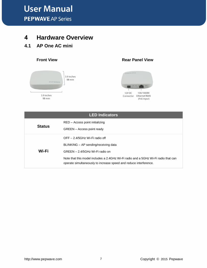
4 Hardware Overview
4.1 AP One AC mini
Front View Rear Panel View
LED Indicators
Status RED – Access point initializing
GREEN – Access point ready
Wi-Fi
OFF – 2.4/5GHz Wi-Fi radio off
BLINKING – AP sending/receiving data
GREEN – 2.4/5GHz Wi-Fi radio on
Note that this model includes a 2.4GHz Wi-Fi radio and a 5GHz Wi-Fi radio that can
operate simultaneously to increase speed and reduce interference.
User Manual
http://www.pepwave.com 8 Copyright © 2015 Pepwave
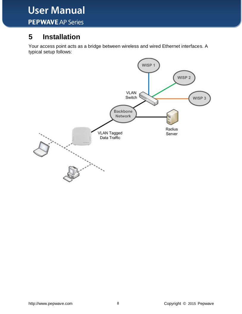
5 Installation
Your access point acts as a bridge between wireless and wired Ethernet interfaces. A
typical setup follows:
User Manual
http://www.pepwave.com 9 Copyright © 2015 Pepwave
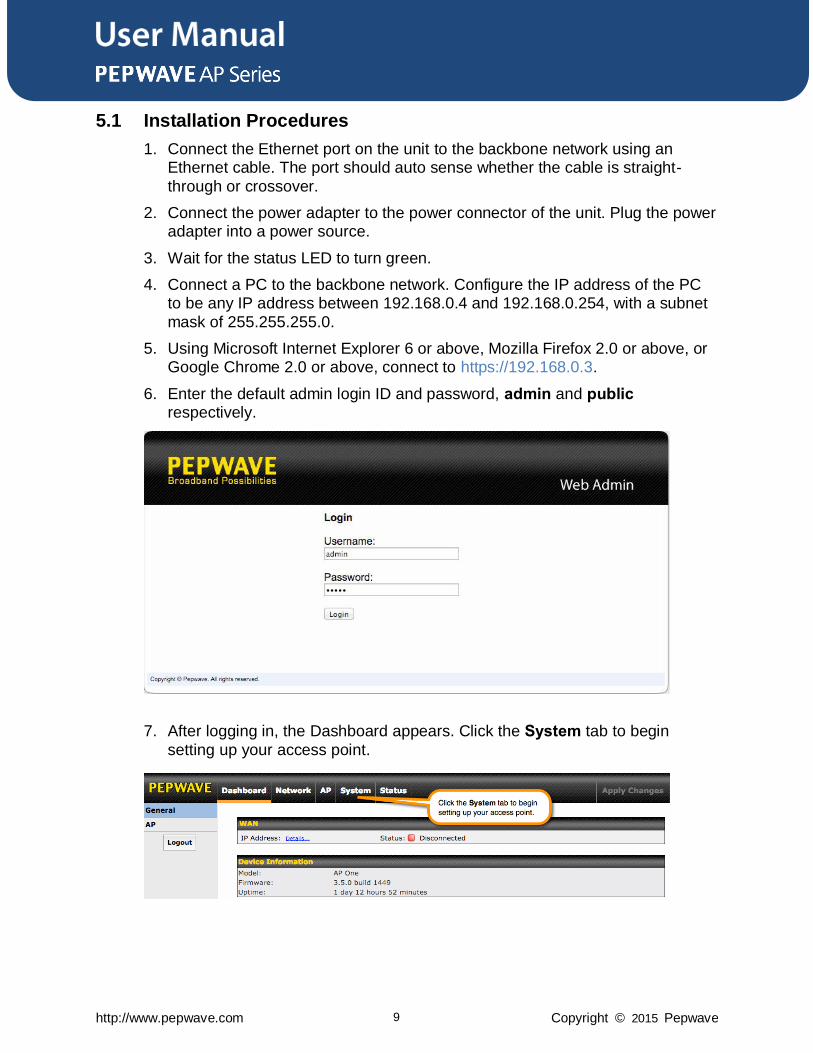
5.1 Installation Procedures
1. Connect the Ethernet port on the unit to the backbone network using an Ethernet cable. The port should auto sense whether the cable is straight-
through or crossover.
2. Connect the power adapter to the power connector of the unit. Plug the power adapter into a power source.
3. Wait for the status LED to turn green.
4. Connect a PC to the backbone network. Configure the IP address of the PC to be any IP address between 192.168.0.4 and 192.168.0.254, with a subnet
mask of 255.255.255.0.
5. Using Microsoft Internet Explorer 6 or above, Mozilla Firefox 2.0 or above, or Google Chrome 2.0 or above, connect to https://192.168.0.3.
6. Enter the default admin login ID and password, admin and public respectively.
7. After logging in, the Dashboard appears. Click the System tab to begin
setting up your access point.
User Manual
http://www.pepwave.com 10 Copyright © 2015 Pepwave
6 Using the Dashboard
The Dashboard section contains a number of displays to keep you up-to-date on your
access point’s status and operation.
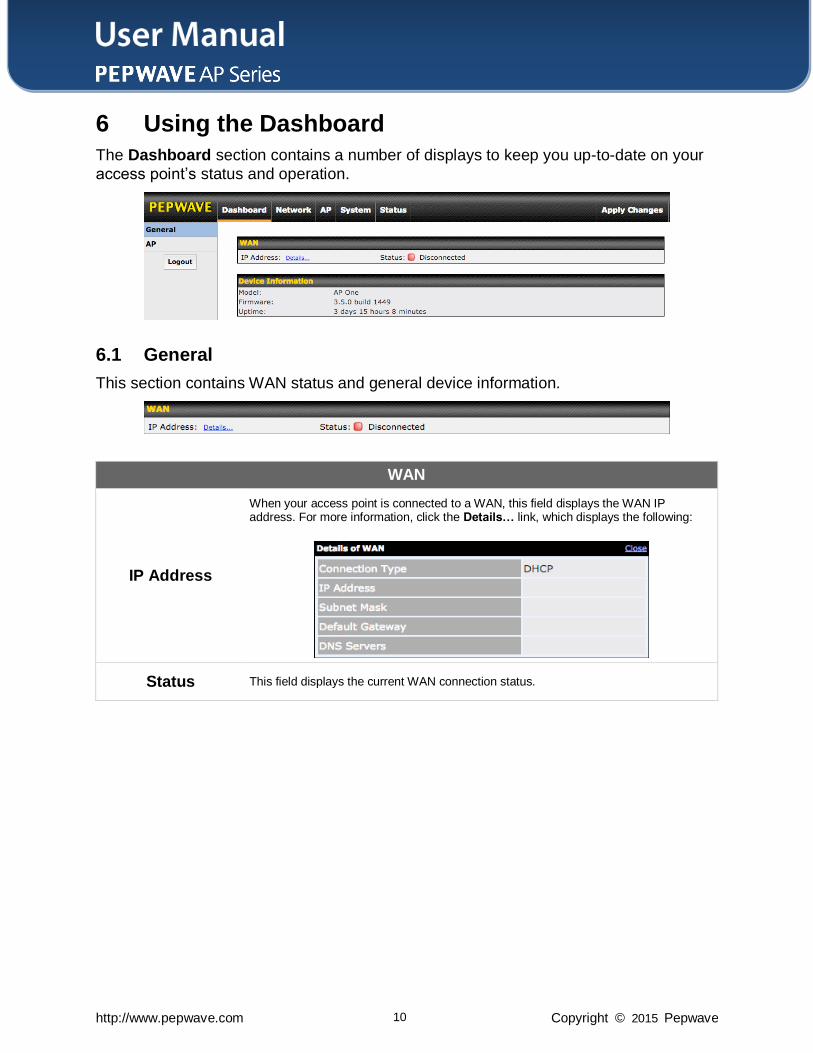
6.1 General
This section contains WAN status and general device information.
WAN
IP Address
When your access point is connected to a WAN, this field displays the WAN IP address. For more information, click the Details… link, which displays the following:
Status This field displays the current WAN connection status.
User Manual
http://www.pepwave.com 11 Copyright © 2015 Pepwave
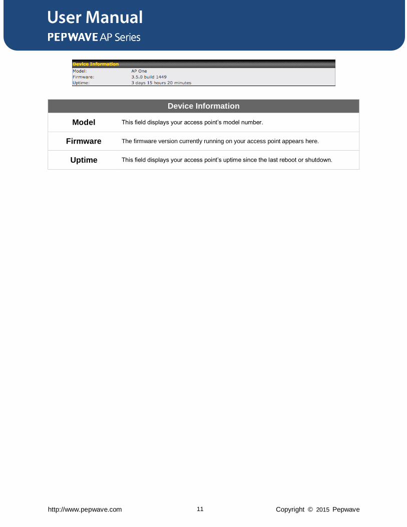
Device Information
Model This field displays your access point’s model number.
Firmware The firmware version currently running on your access point appears here.
Uptime This field displays your access point’s uptime since the last reboot or shutdown.
User Manual
http://www.pepwave.com 12 Copyright © 2015 Pepwave
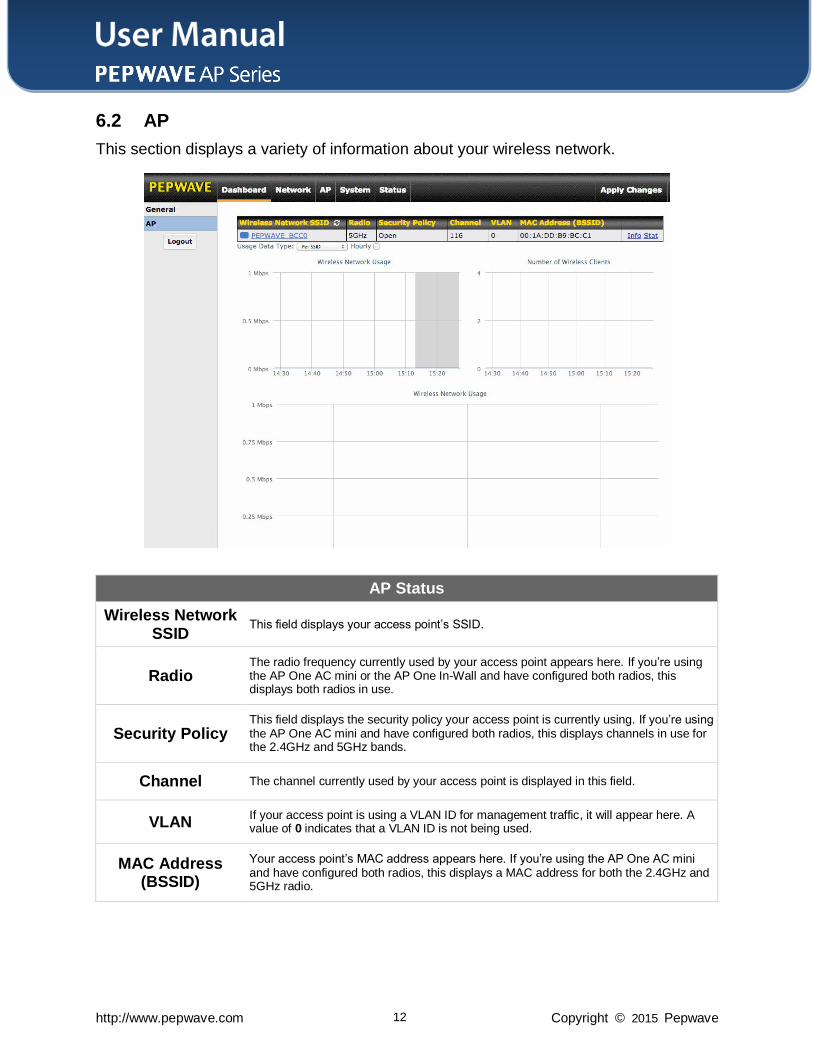
6.2 AP
This section displays a variety of information about your wireless network.
AP Status
Wireless Network SSID
This field displays your access point’s SSID.
Radio The radio frequency currently used by your access point appears here. If you’re using the AP One AC mini or the AP One In-Wall and have configured both radios, this displays both radios in use.
Security Policy This field displays the security policy your access point is currently using. If you’re using the AP One AC mini and have configured both radios, this displays channels in use for the 2.4GHz and 5GHz bands.
Channel The channel currently used by your access point is displayed in this field.
VLAN If your access point is using a VLAN ID for management traffic, it will appear here. A value of 0 indicates that a VLAN ID is not being used.
MAC Address (BSSID)
Your access point’s MAC address appears here. If you’re using the AP One AC mini and have configured both radios, this displays a MAC address for both the 2.4GHz and 5GHz radio.
User Manual
http://www.pepwave.com 13 Copyright © 2015 Pepwave
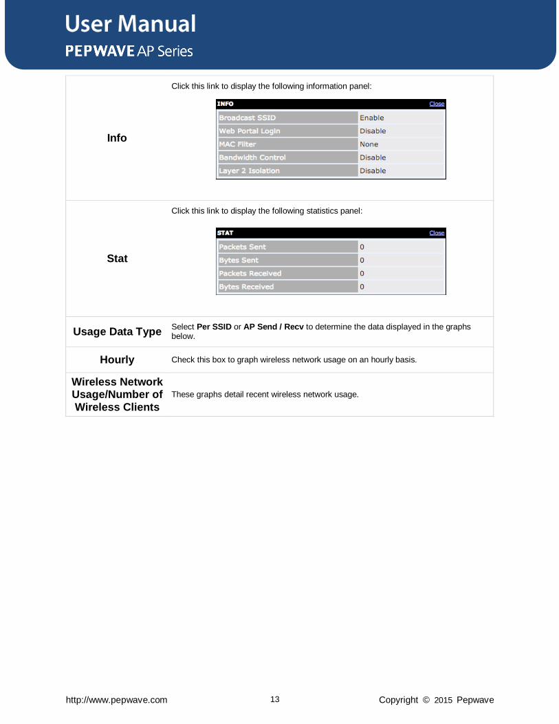
Info
Click this link to display the following information panel:
Stat
Click this link to display the following statistics panel:
Usage Data Type Select Per SSID or AP Send / Recv to determine the data displayed in the graphs below.
Hourly Check this box to graph wireless network usage on an hourly basis.
Wireless Network Usage/Number of Wireless Clients
These graphs detail recent wireless network usage.
User Manual
http://www.pepwave.com 14 Copyright © 2015 Pepwave
7 Configuration
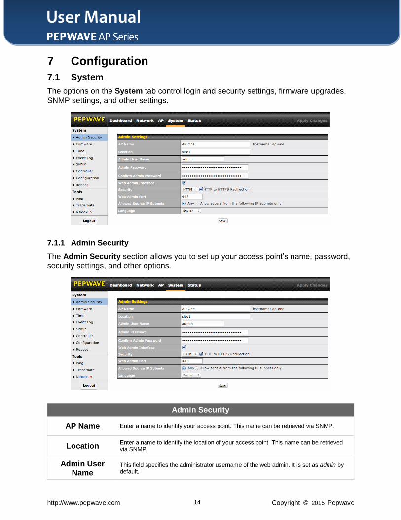
7.1 System
The options on the System tab control login and security settings, firmware upgrades,
SNMP settings, and other settings.
7.1.1 Admin Security
The Admin Security section allows you to set up your access point’s name, password, security settings, and other options.
Admin Security
AP Name Enter a name to identify your access point. This name can be retrieved via SNMP.
Location Enter a name to identify the location of your access point. This name can be retrieved via SNMP.
Admin User Name
This field specifies the administrator username of the web admin. It is set as admin by default.
User Manual
http://www.pepwave.com 15 Copyright © 2015 Pepwave
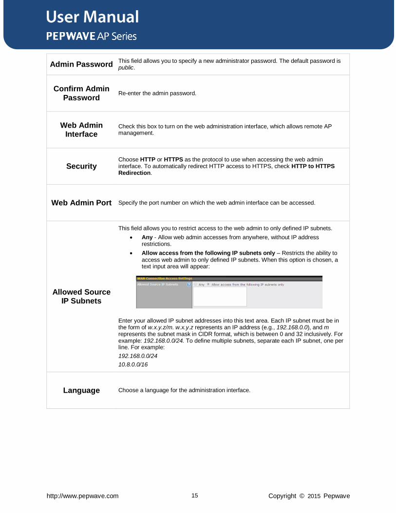
Admin Password This field allows you to specify a new administrator password. The default password is public.
Confirm Admin Password
Re-enter the admin password.
Web Admin Interface
Check this box to turn on the web administration interface, which allows remote AP management.
Security Choose HTTP or HTTPS as the protocol to use when accessing the web admin interface. To automatically redirect HTTP access to HTTPS, check HTTP to HTTPS Redirection.
Web Admin Port Specify the port number on which the web admin interface can be accessed.
Allowed Source IP Subnets
This field allows you to restrict access to the web admin to only defined IP subnets.
Any - Allow web admin accesses from anywhere, without IP address restrictions.
Allow access from the following IP subnets only – Restricts the ability to access web admin to only defined IP subnets. When this option is chosen, a text input area will appear:
Enter your allowed IP subnet addresses into this text area. Each IP subnet must be in the form of w.x.y.z/m. w.x.y.z represents an IP address (e.g., 192.168.0.0), and m represents the subnet mask in CIDR format, which is between 0 and 32 inclusively. For example: 192.168.0.0/24. To define multiple subnets, separate each IP subnet, one per line. For example:
192.168.0.0/24
10.8.0.0/16
Language Choose a language for the administration interface.
User Manual
http://www.pepwave.com 16 Copyright © 2015 Pepwave
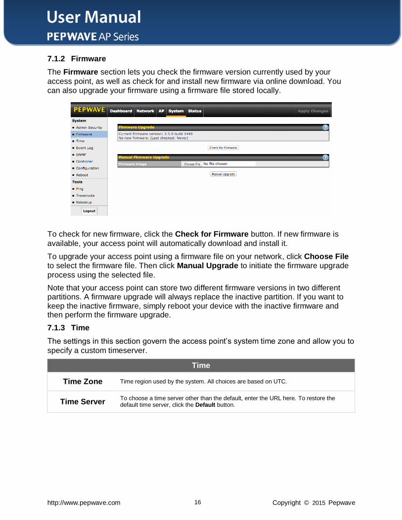
7.1.2 Firmware
The Firmware section lets you check the firmware version currently used by your
access point, as well as check for and install new firmware via online download. You can also upgrade your firmware using a firmware file stored locally.
To check for new firmware, click the Check for Firmware button. If new firmware is
available, your access point will automatically download and install it.
To upgrade your access point using a firmware file on your network, click Choose File to select the firmware file. Then click Manual Upgrade to initiate the firmware upgrade
process using the selected file.
Note that your access point can store two different firmware versions in two different partitions. A firmware upgrade will always replace the inactive partition. If you want to keep the inactive firmware, simply reboot your device with the inactive firmware and then perform the firmware upgrade.
7.1.3 Time
The settings in this section govern the access point’s system time zone and allow you to
specify a custom timeserver.
Time
Time Zone Time region used by the system. All choices are based on UTC.
Time Server To choose a time server other than the default, enter the URL here. To restore the default time server, click the Default button.
User Manual
http://www.pepwave.com 17 Copyright © 2015 Pepwave
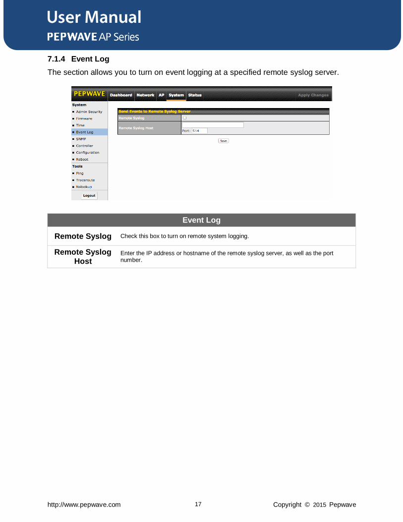
7.1.4 Event Log
The section allows you to turn on event logging at a specified remote syslog server.
Event Log
Remote Syslog Check this box to turn on remote system logging.
Remote Syslog Host
Enter the IP address or hostname of the remote syslog server, as well as the port number.
User Manual
http://www.pepwave.com 18 Copyright © 2015 Pepwave
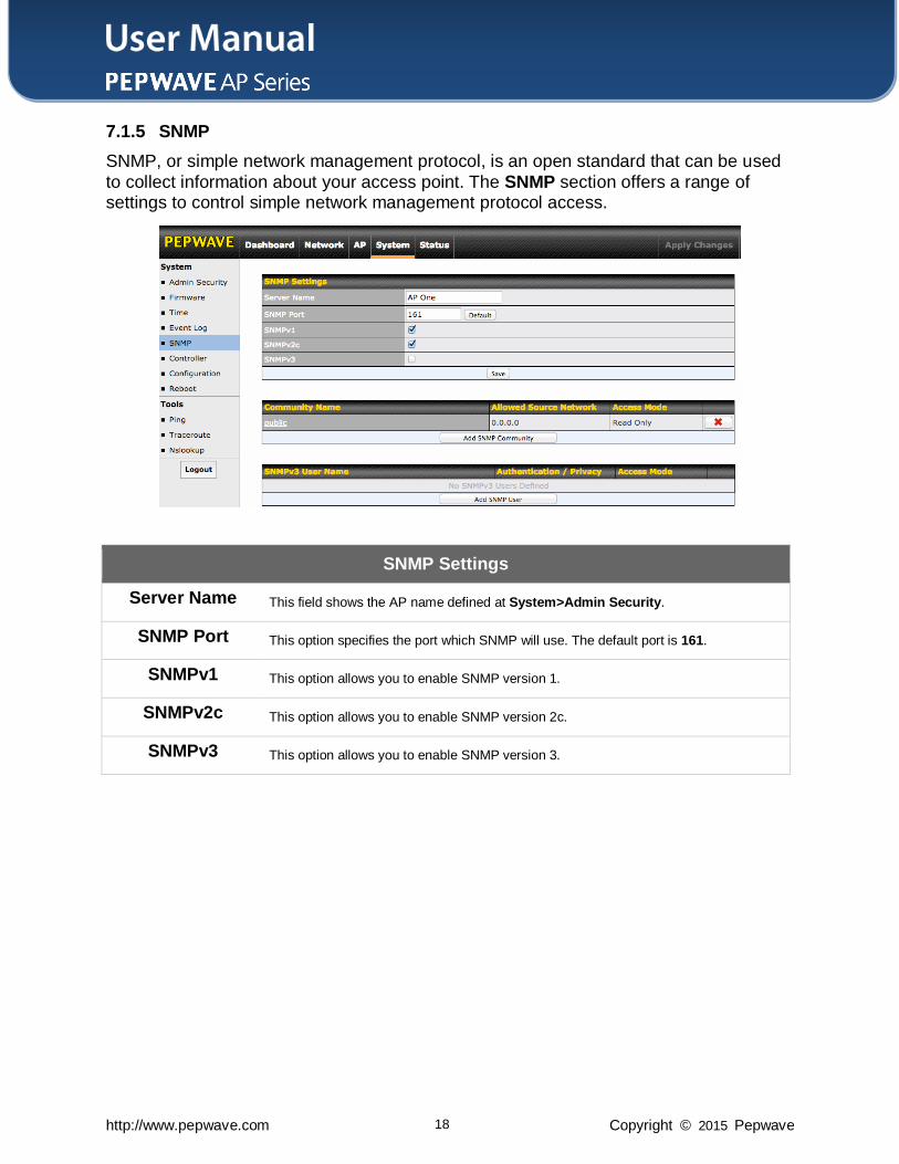
7.1.5 SNMP
SNMP, or simple network management protocol, is an open standard that can be used
to collect information about your access point. The SNMP section offers a range of settings to control simple network management protocol access.
SNMP Settings
Server Name This field shows the AP name defined at System>Admin Security.
SNMP Port This option specifies the port which SNMP will use. The default port is 161.
SNMPv1 This option allows you to enable SNMP version 1.
SNMPv2c This option allows you to enable SNMP version 2c.
SNMPv3 This option allows you to enable SNMP version 3.
User Manual
http://www.pepwave.com 19 Copyright © 2015 Pepwave
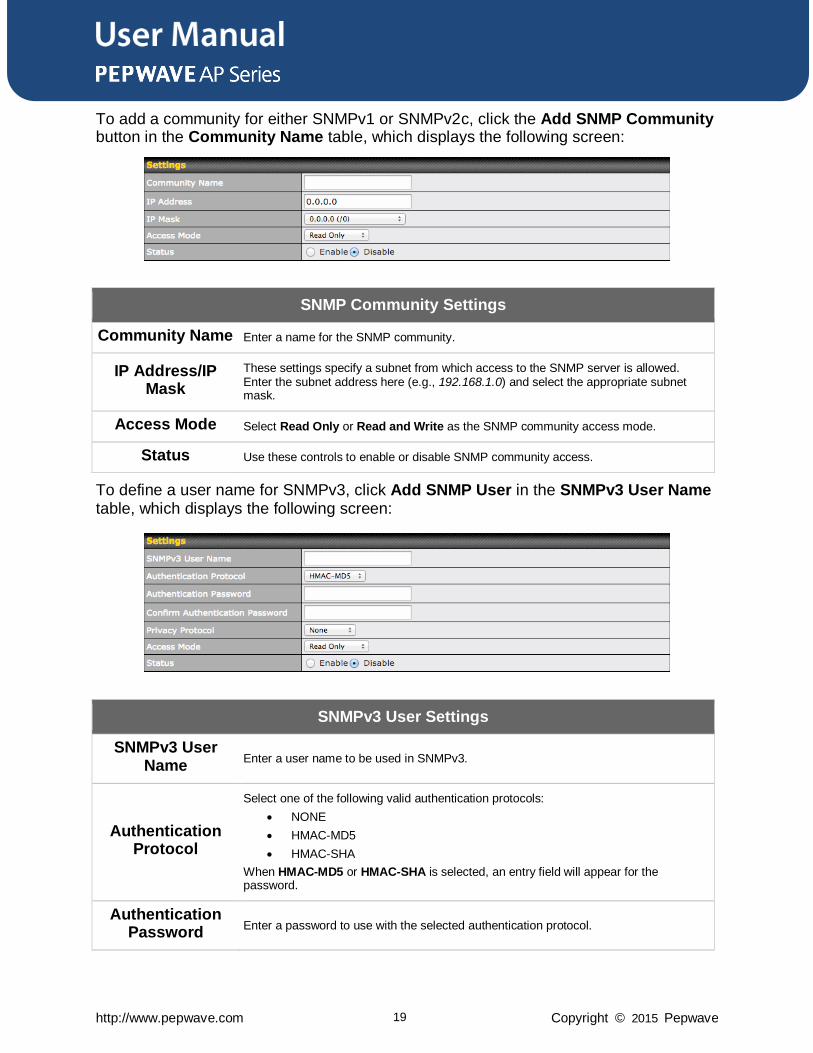
To add a community for either SNMPv1 or SNMPv2c, click the Add SNMP Community button in the Community Name table, which displays the following screen:
SNMP Community Settings
Community Name Enter a name for the SNMP community.
IP Address/IP Mask
These settings specify a subnet from which access to the SNMP server is allowed. Enter the subnet address here (e.g., 192.168.1.0) and select the appropriate subnet mask.
Access Mode Select Read Only or Read and Write as the SNMP community access mode.
Status Use these controls to enable or disable SNMP community access.
To define a user name for SNMPv3, click Add SNMP User in the SNMPv3 User Name table, which displays the following screen:
SNMPv3 User Settings
SNMPv3 User Name
Enter a user name to be used in SNMPv3.
Authentication Protocol
Select one of the following valid authentication protocols:
NONE
HMAC-MD5
HMAC-SHA
When HMAC-MD5 or HMAC-SHA is selected, an entry field will appear for the password.
Authentication Password
Enter a password to use with the selected authentication protocol.
User Manual
http://www.pepwave.com 20 Copyright © 2015 Pepwave
Confirm Authentication
Password Re-enter the authentication password.
Privacy Protocol Select None or CBC-DES as the SNMPv3 privacy protocol. When CBC-DES is selected, an entry field will appear for the password.
Access Mode Select Read Only or Read and Write as the SNMPv3 access mode.
Status Use these controls to enable or disable SNMPv3 access.
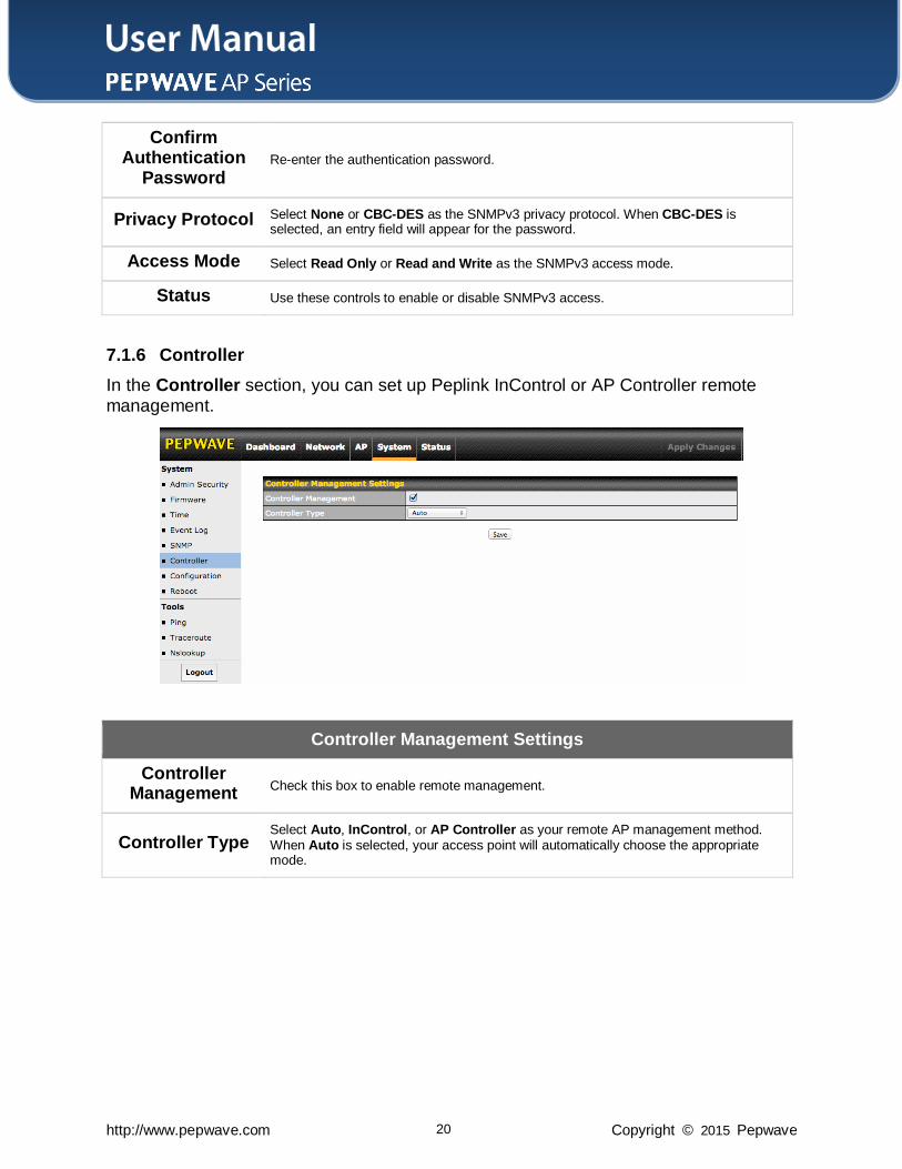
7.1.6 Controller
In the Controller section, you can set up Peplink InControl or AP Controller remote management.
Controller Management Settings
Controller Management
Check this box to enable remote management.
Controller Type Select Auto, InControl, or AP Controller as your remote AP management method. When Auto is selected, your access point will automatically choose the appropriate mode.
User Manual
http://www.pepwave.com 21 Copyright © 2015 Pepwave
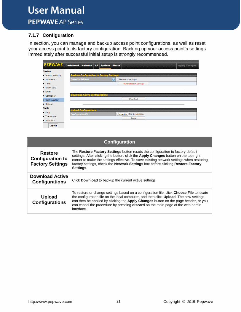
7.1.7 Configuration
In section, you can manage and backup access point configurations, as well as reset
your access point to its factory configuration. Backing up your access point’s settings immediately after successful initial setup is strongly recommended.
Configuration
Restore Configuration to Factory Settings
The Restore Factory Settings button resets the configuration to factory default settings. After clicking the button, click the Apply Changes button on the top right corner to make the settings effective. To save existing network settings when restoring factory settings, check the Network Settings box before clicking Restore Factory Settings.
Download Active Configurations Click Download to backup the current active settings.
Upload Configurations
To restore or change settings based on a configuration file, click Choose File to locate the configuration file on the local computer, and then click Upload. The new settings can then be applied by clicking the Apply Changes button on the page header, or you can cancel the procedure by pressing discard on the main page of the web admin interface.
User Manual
http://www.pepwave.com 22 Copyright © 2015 Pepwave
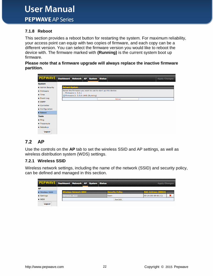
7.1.8 Reboot
This section provides a reboot button for restarting the system. For maximum reliability, your access point can equip with two copies of firmware, and each copy can be a different version. You can select the firmware version you would like to reboot the device with. The firmware marked with (Running) is the current system boot up firmware.
Please note that a firmware upgrade will always replace the inactive firmware partition.
7.2 AP
Use the controls on the AP tab to set the wireless SSID and AP settings, as well as wireless distribution system (WDS) settings.
7.2.1 Wireless SSID
Wireless network settings, including the name of the network (SSID) and security policy, can be defined and managed in this section.
User Manual
http://www.pepwave.com 23 Copyright © 2015 Pepwave
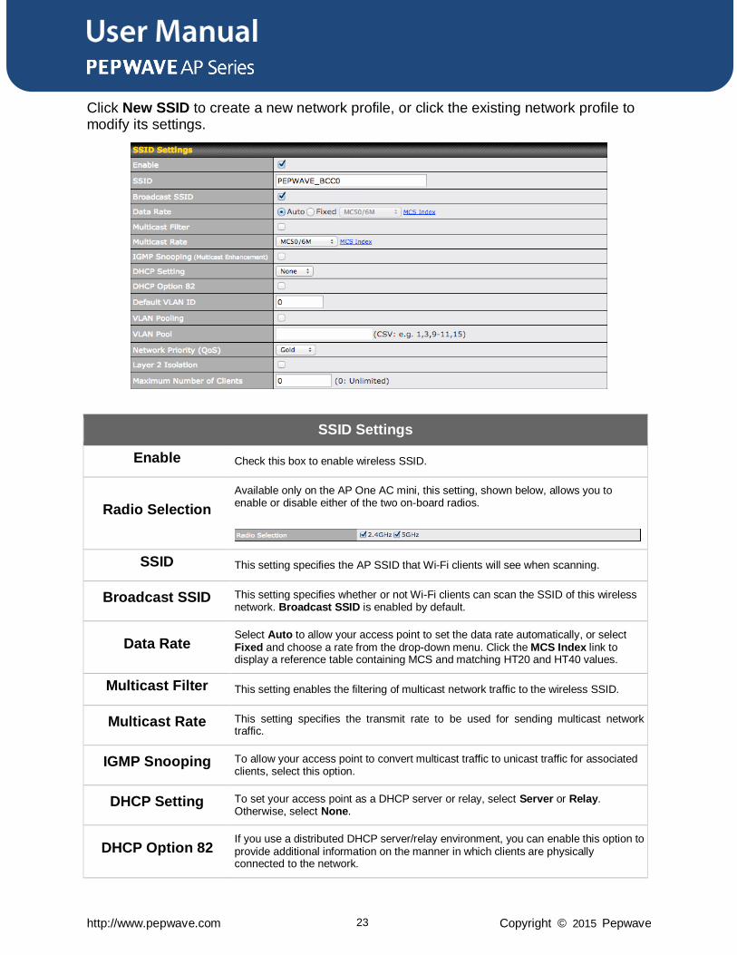
Click New SSID to create a new network profile, or click the existing network profile to modify its settings.
SSID Settings
Enable Check this box to enable wireless SSID.
Radio Selection
Available only on the AP One AC mini, this setting, shown below, allows you to enable or disable either of the two on-board radios.
SSID This setting specifies the AP SSID that Wi-Fi clients will see when scanning.
Broadcast SSID This setting specifies whether or not Wi-Fi clients can scan the SSID of this wireless network. Broadcast SSID is enabled by default.
Data Rate Select Auto to allow your access point to set the data rate automatically, or select Fixed and choose a rate from the drop-down menu. Click the MCS Index link to display a reference table containing MCS and matching HT20 and HT40 values.
Multicast Filter This setting enables the filtering of multicast network traffic to the wireless SSID.
Multicast Rate This setting specifies the transmit rate to be used for sending multicast network traffic.
IGMP Snooping To allow your access point to convert multicast traffic to unicast traffic for associated clients, select this option.
DHCP Setting To set your access point as a DHCP server or relay, select Server or Relay. Otherwise, select None.
DHCP Option 82 If you use a distributed DHCP server/relay environment, you can enable this option to provide additional information on the manner in which clients are physically connected to the network.
User Manual
http://www.pepwave.com 24 Copyright © 2015 Pepwave
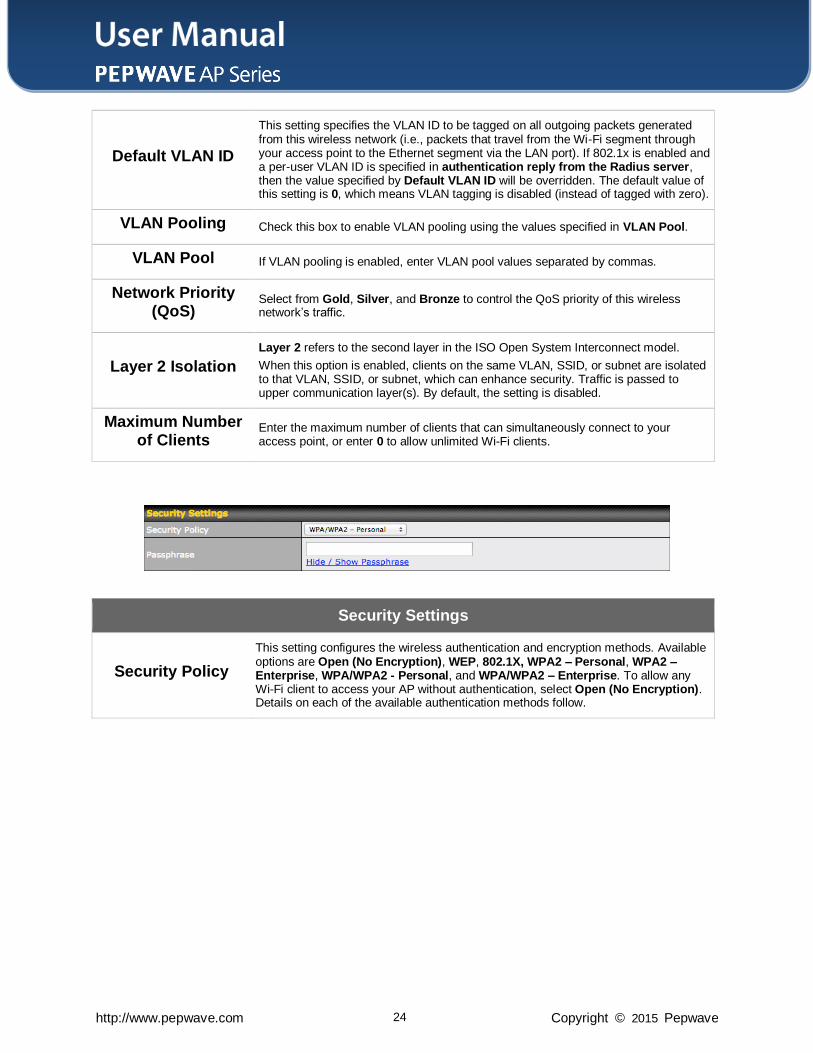
Default VLAN ID
This setting specifies the VLAN ID to be tagged on all outgoing packets generated from this wireless network (i.e., packets that travel from the Wi-Fi segment through your access point to the Ethernet segment via the LAN port). If 802.1x is enabled and a per-user VLAN ID is specified in authentication reply from the Radius server, then the value specified by Default VLAN ID will be overridden. The default value of this setting is 0, which means VLAN tagging is disabled (instead of tagged with zero).
VLAN Pooling Check this box to enable VLAN pooling using the values specified in VLAN Pool.
VLAN Pool If VLAN pooling is enabled, enter VLAN pool values separated by commas.
Network Priority (QoS)
Select from Gold, Silver, and Bronze to control the QoS priority of this wireless network’s traffic.
Layer 2 Isolation
Layer 2 refers to the second layer in the ISO Open System Interconnect model.
When this option is enabled, clients on the same VLAN, SSID, or subnet are isolated to that VLAN, SSID, or subnet, which can enhance security. Traffic is passed to upper communication layer(s). By default, the setting is disabled.
Maximum Number of Clients
Enter the maximum number of clients that can simultaneously connect to your access point, or enter 0 to allow unlimited Wi-Fi clients.
Security Settings
Security Policy
This setting configures the wireless authentication and encryption methods. Available options are Open (No Encryption), WEP, 802.1X, WPA2 – Personal, WPA2 – Enterprise, WPA/WPA2 - Personal, and WPA/WPA2 – Enterprise. To allow any Wi-Fi client to access your AP without authentication, select Open (No Encryption). Details on each of the available authentication methods follow.
User Manual
http://www.pepwave.com 25 Copyright © 2015 Pepwave
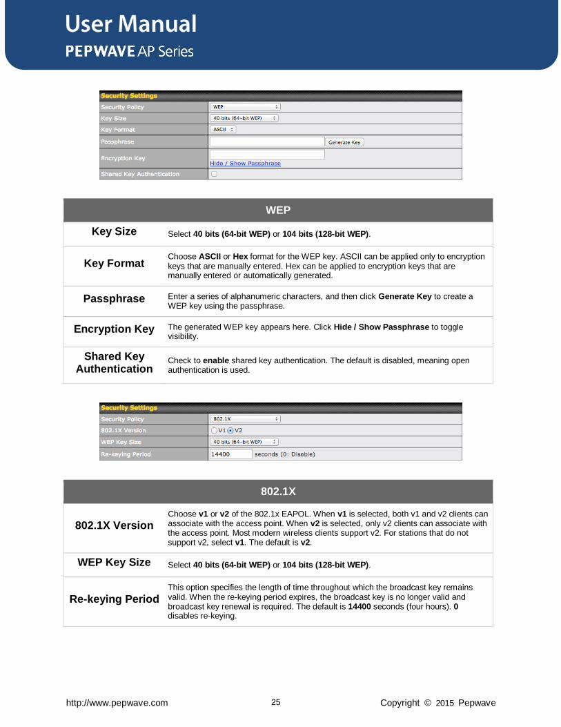
WEP
Key Size Select 40 bits (64-bit WEP) or 104 bits (128-bit WEP).
Key Format Choose ASCII or Hex format for the WEP key. ASCII can be applied only to encryption keys that are manually entered. Hex can be applied to encryption keys that are manually entered or automatically generated.
Passphrase Enter a series of alphanumeric characters, and then click Generate Key to create a WEP key using the passphrase.
Encryption Key The generated WEP key appears here. Click Hide / Show Passphrase to toggle visibility.
Shared Key Authentication
Check to enable shared key authentication. The default is disabled, meaning open authentication is used.
802.1X
802.1X Version Choose v1 or v2 of the 802.1x EAPOL. When v1 is selected, both v1 and v2 clients can associate with the access point. When v2 is selected, only v2 clients can associate with the access point. Most modern wireless clients support v2. For stations that do not support v2, select v1. The default is v2.
WEP Key Size Select 40 bits (64-bit WEP) or 104 bits (128-bit WEP).
Re-keying Period This option specifies the length of time throughout which the broadcast key remains valid. When the re-keying period expires, the broadcast key is no longer valid and broadcast key renewal is required. The default is 14400 seconds (four hours). 0 disables re-keying.
User Manual
http://www.pepwave.com 26 Copyright © 2015 Pepwave
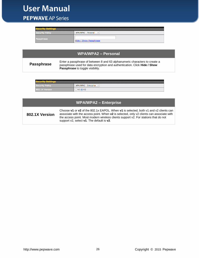
WPA/WPA2 – Personal
Passphrase Enter a passphrase of between 8 and 63 alphanumeric characters to create a passphrase used for data encryption and authentication. Click Hide / Show Passphrase to toggle visibility.
WPA/WPA2 – Enterprise
802.1X Version Choose v1 or v2 of the 802.1x EAPOL. When v1 is selected, both v1 and v2 clients can associate with the access point. When v2 is selected, only v2 clients can associate with the access point. Most modern wireless clients support v2. For stations that do not support v2, select v1. The default is v2.
User Manual
http://www.pepwave.com 27 Copyright © 2015 Pepwave
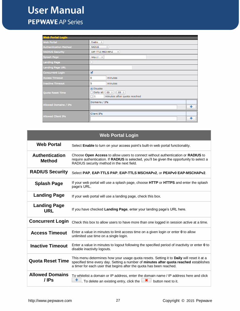
Web Portal Login
Web Portal Select Enable to turn on your access point’s built-in web portal functionality.
Authentication Method
Choose Open Access to allow users to connect without authentication or RADIUS to require authentication. If RADIUS is selected, you’ll be given the opportunity to select a RADIUS security method in the next field.
RADIUS Security Select PAP, EAP-TTLS PAP, EAP-TTLS MSCHAPv2, or PEAPv0 EAP-MSCHAPv2.
Splash Page If your web portal will use a splash page, choose HTTP or HTTPS and enter the splash page’s URL.
Landing Page If your web portal will use a landing page, check this box.
Landing Page URL If you have checked Landing Page, enter your landing page’s URL here.
Concurrent Login Check this box to allow users to have more than one logged in session active at a time.
Access Timeout Enter a value in minutes to limit access time on a given login or enter 0 to allow unlimited use time on a single login.
Inactive Timeout Enter a value in minutes to logout following the specified period of inactivity or enter 0 to disable inactivity logouts.
Quota Reset Time This menu determines how your usage quota resets. Setting it to Daily will reset it at a specified time every day. Setting a number of minutes after quota reached establishes a timer for each user that begins after the quota has been reached.
Allowed Domains / IPs
To whitelist a domain or IP address, enter the domain name / IP address here and click
. To delete an existing entry, click the button next to it.
User Manual
http://www.pepwave.com 28 Copyright © 2015 Pepwave
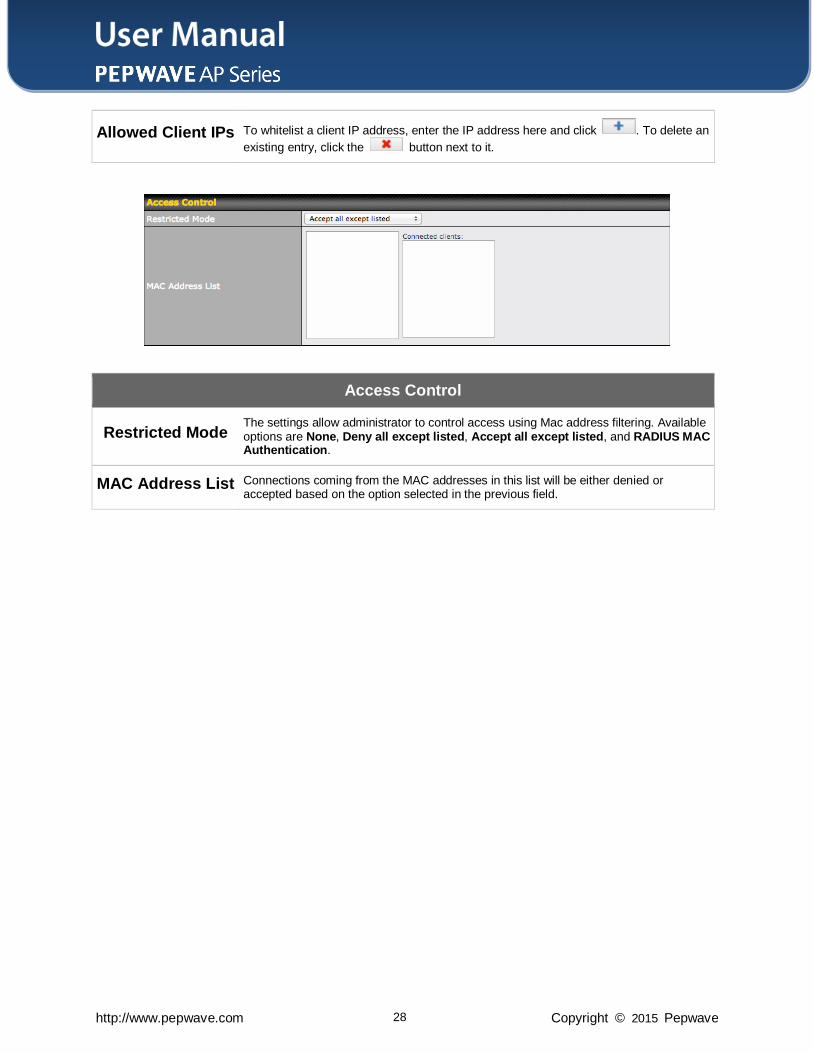
Allowed Client IPs To whitelist a client IP address, enter the IP address here and click . To delete an
existing entry, click the button next to it.
Access Control
Restricted Mode The settings allow administrator to control access using Mac address filtering. Available options are None, Deny all except listed, Accept all except listed, and RADIUS MAC Authentication.
MAC Address List Connections coming from the MAC addresses in this list will be either denied or accepted based on the option selected in the previous field.
User Manual
http://www.pepwave.com 29 Copyright © 2015 Pepwave
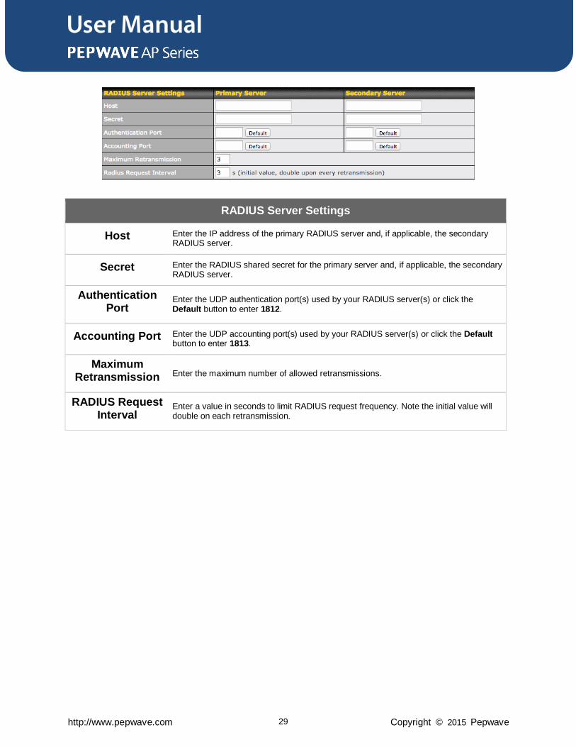
RADIUS Server Settings
Host Enter the IP address of the primary RADIUS server and, if applicable, the secondary RADIUS server.
Secret Enter the RADIUS shared secret for the primary server and, if applicable, the secondary RADIUS server.
Authentication Port
Enter the UDP authentication port(s) used by your RADIUS server(s) or click the Default button to enter 1812.
Accounting Port Enter the UDP accounting port(s) used by your RADIUS server(s) or click the Default button to enter 1813.
Maximum Retransmission Enter the maximum number of allowed retransmissions.
RADIUS Request Interval
Enter a value in seconds to limit RADIUS request frequency. Note the initial value will double on each retransmission.
User Manual
http://www.pepwave.com 30 Copyright © 2015 Pepwave
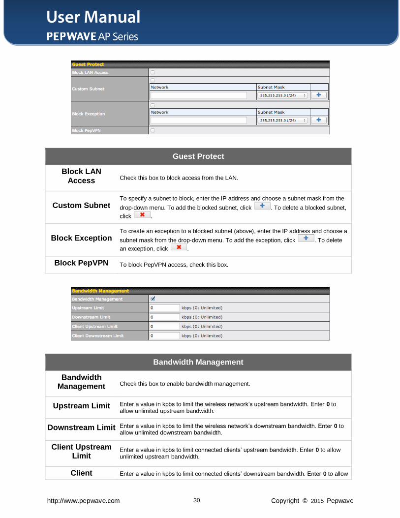
Guest Protect
Block LAN Access Check this box to block access from the LAN.
Custom Subnet To specify a subnet to block, enter the IP address and choose a subnet mask from the
drop-down menu. To add the blocked subnet, click . To delete a blocked subnet,
click .
Block Exception To create an exception to a blocked subnet (above), enter the IP address and choose a
subnet mask from the drop-down menu. To add the exception, click . To delete
an exception, click .
Block PepVPN To block PepVPN access, check this box.
Bandwidth Management
Bandwidth Management Check this box to enable bandwidth management.
Upstream Limit Enter a value in kpbs to limit the wireless network’s upstream bandwidth. Enter 0 to allow unlimited upstream bandwidth.
Downstream Limit Enter a value in kpbs to limit the wireless network’s downstream bandwidth. Enter 0 to allow unlimited downstream bandwidth.
Client Upstream Limit
Enter a value in kpbs to limit connected clients’ upstream bandwidth. Enter 0 to allow unlimited upstream bandwidth.
Client Enter a value in kpbs to limit connected clients’ downstream bandwidth. Enter 0 to allow
User Manual
http://www.pepwave.com 31 Copyright © 2015 Pepwave
Downstream Limit unlimited downstream bandwidth.
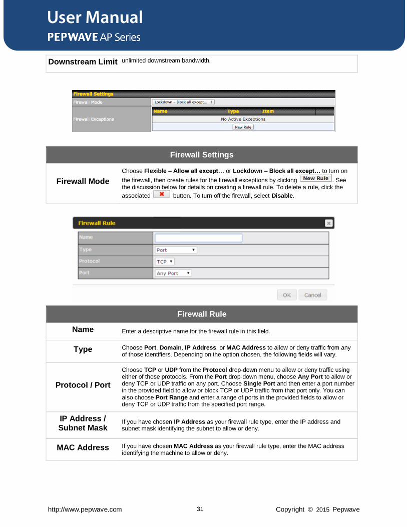
Firewall Settings
Firewall Mode
Choose Flexible – Allow all except… or Lockdown – Block all except… to turn on
the firewall, then create rules for the firewall exceptions by clicking . See the discussion below for details on creating a firewall rule. To delete a rule, click the
associated button. To turn off the firewall, select Disable.
Firewall Rule
Name Enter a descriptive name for the firewall rule in this field.
Type Choose Port, Domain, IP Address, or MAC Address to allow or deny traffic from any of those identifiers. Depending on the option chosen, the following fields will vary.
Protocol / Port
Choose TCP or UDP from the Protocol drop-down menu to allow or deny traffic using either of those protocols. From the Port drop-down menu, choose Any Port to allow or deny TCP or UDP traffic on any port. Choose Single Port and then enter a port number in the provided field to allow or block TCP or UDP traffic from that port only. You can also choose Port Range and enter a range of ports in the provided fields to allow or deny TCP or UDP traffic from the specified port range.
IP Address / Subnet Mask
If you have chosen IP Address as your firewall rule type, enter the IP address and subnet mask identifying the subnet to allow or deny.
MAC Address If you have chosen MAC Address as your firewall rule type, enter the MAC address identifying the machine to allow or deny.
User Manual
http://www.pepwave.com 32 Copyright © 2015 Pepwave
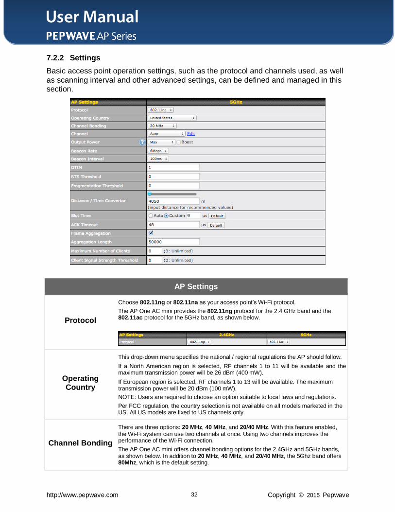
7.2.2 Settings
Basic access point operation settings, such as the protocol and channels used, as well
as scanning interval and other advanced settings, can be defined and managed in this section.
AP Settings
Protocol
Choose 802.11ng or 802.11na as your access point’s Wi-Fi protocol.
The AP One AC mini provides the 802.11ng protocol for the 2.4 GHz band and the 802.11ac protocol for the 5GHz band, as shown below.
Operating Country
This drop-down menu specifies the national / regional regulations the AP should follow.
If a North American region is selected, RF channels 1 to 11 will be available and the maximum transmission power will be 26 dBm (400 mW).
If European region is selected, RF channels 1 to 13 will be available. The maximum transmission power will be 20 dBm (100 mW).
NOTE: Users are required to choose an option suitable to local laws and regulations.
Per FCC regulation, the country selection is not available on all models marketed in the US. All US models are fixed to US channels only.
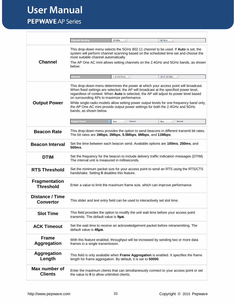
Channel Bonding
There are three options: 20 MHz, 40 MHz, and 20/40 MHz. With this feature enabled, the Wi-Fi system can use two channels at once. Using two channels improves the performance of the Wi-Fi connection.
The AP One AC mini offers channel bonding options for the 2.4GHz and 5GHz bands, as shown below. In addition to 20 MHz, 40 MHz, and 20/40 MHz, the 5Ghz band offers 80Mhz, which is the default setting.
User Manual
http://www.pepwave.com 33 Copyright © 2015 Pepwave
Channel
This drop-down menu selects the 5GHz 802.11 channel to be used. If Auto is set, the system will perform channel scanning based on the scheduled time set and choose the most suitable channel automatically.
The AP One AC mini allows setting channels on the 2.4GHz and 5GHz bands, as shown below.
Output Power
This drop-down menu determines the power at which your access point will broadcast. When fixed settings are selected, the AP will broadcast at the specified power level, regardless of context. When Auto is selected, the AP will adjust its power level based on surrounding APs to maximize performance.
While single-radio models allow setting power output levels for one frequency band only, the AP One AC mini provide output power settings for both the 2.4GHz and 5GHz bands, as shown below.
Beacon Rate This drop-down menu provides the option to send beacons in different transmit bit rates. The bit rates are 1Mbps, 2Mbps, 5.5Mbps, 6Mbps, and 11Mbps.
Beacon Interval Set the time between each beacon send. Available options are 100ms, 250ms, and 500ms.
DTIM Set the frequency for the beacon to include delivery traffic indication messages (DTIM). The interval unit is measured in milliseconds.
RTS Threshold Set the minimum packet size for your access point to send an RTS using the RTS/CTS handshake. Setting 0 disables this feature.
Fragmentation Threshold Enter a value to limit the maximum frame size, which can improve performance.
Distance / Time Convertor This slider and text entry field can be used to interactively set slot time.
Slot Time This field provides the option to modify the unit wait time before your access point
transmits. The default value is 9μs.
ACK Timeout Set the wait time to receive an acknowledgement packet before retransmitting. The
default value is 48μs.
Frame Aggregation
With this feature enabled, throughput will be increased by sending two or more data frames in a single transmission.
Aggregation Length
This field is only available when Frame Aggregation is enabled. It specifies the frame length for frame aggregation. By default, it is set to 50000.
Max number of Clients
Enter the maximum clients that can simultaneously connect to your access point or set the value to 0 to allow unlimited clients.
User Manual
http://www.pepwave.com 34 Copyright © 2015 Pepwave
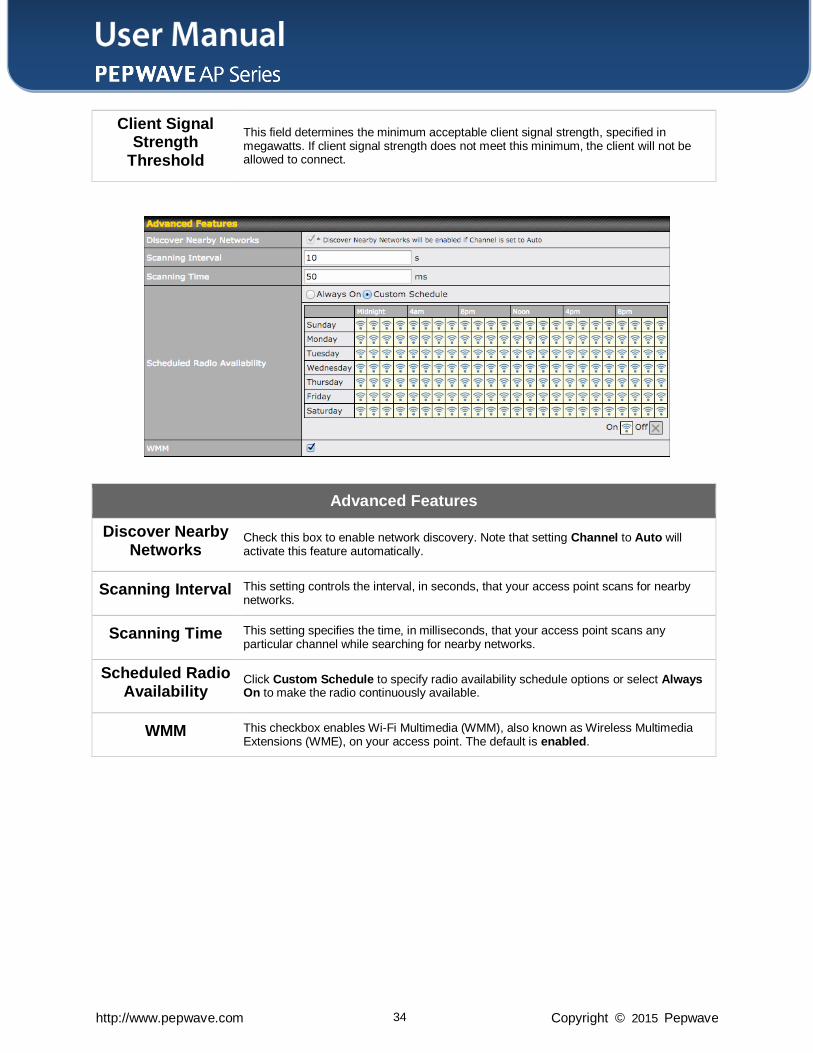
Client Signal Strength
Threshold
This field determines the minimum acceptable client signal strength, specified in megawatts. If client signal strength does not meet this minimum, the client will not be allowed to connect.
Advanced Features
Discover Nearby Networks
Check this box to enable network discovery. Note that setting Channel to Auto will activate this feature automatically.
Scanning Interval This setting controls the interval, in seconds, that your access point scans for nearby networks.
Scanning Time This setting specifies the time, in milliseconds, that your access point scans any particular channel while searching for nearby networks.
Scheduled Radio Availability
Click Custom Schedule to specify radio availability schedule options or select Always On to make the radio continuously available.
WMM This checkbox enables Wi-Fi Multimedia (WMM), also known as Wireless Multimedia Extensions (WME), on your access point. The default is enabled.
User Manual
http://www.pepwave.com 35 Copyright © 2015 Pepwave
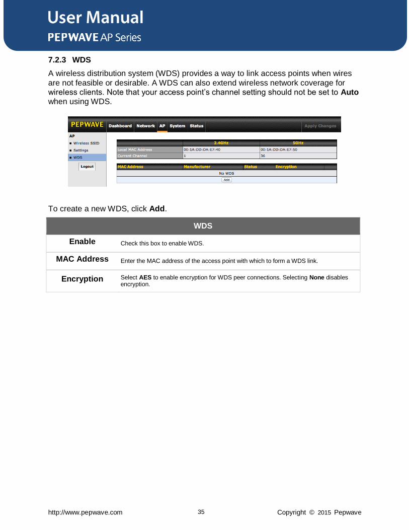
7.2.3 WDS
A wireless distribution system (WDS) provides a way to link access points when wires
are not feasible or desirable. A WDS can also extend wireless network coverage for wireless clients. Note that your access point’s channel setting should not be set to Auto when using WDS.
To create a new WDS, click Add.
WDS
Enable Check this box to enable WDS.
MAC Address Enter the MAC address of the access point with which to form a WDS link.
Encryption Select AES to enable encryption for WDS peer connections. Selecting None disables encryption.
User Manual
http://www.pepwave.com 36 Copyright © 2015 Pepwave
7.3 Network
The settings on the AP tab control WAN and LAN settings, as well as allow you to set
up PepVPN profiles.
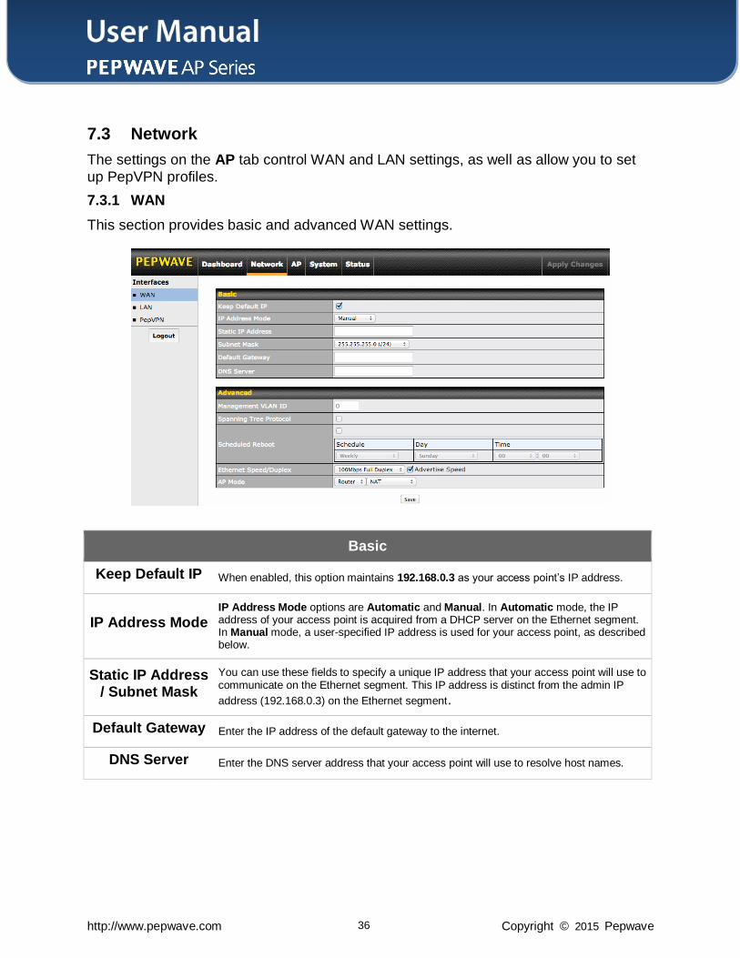
7.3.1 WAN
This section provides basic and advanced WAN settings.
Basic
Keep Default IP When enabled, this option maintains 192.168.0.3 as your access point’s IP address.
IP Address Mode IP Address Mode options are Automatic and Manual. In Automatic mode, the IP address of your access point is acquired from a DHCP server on the Ethernet segment. In Manual mode, a user-specified IP address is used for your access point, as described below.
Static IP Address / Subnet Mask
You can use these fields to specify a unique IP address that your access point will use to communicate on the Ethernet segment. This IP address is distinct from the admin IP
address (192.168.0.3) on the Ethernet segment.
Default Gateway Enter the IP address of the default gateway to the internet.
DNS Server Enter the DNS server address that your access point will use to resolve host names.
User Manual
http://www.pepwave.com 37 Copyright © 2015 Pepwave
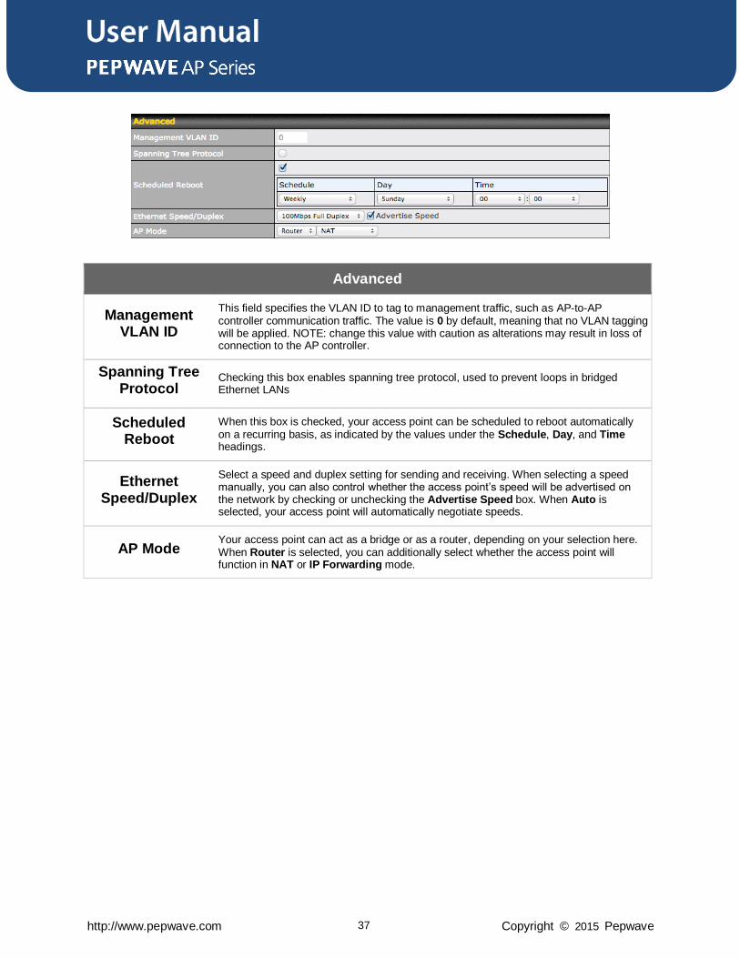
Advanced
Management VLAN ID
This field specifies the VLAN ID to tag to management traffic, such as AP-to-AP controller communication traffic. The value is 0 by default, meaning that no VLAN tagging will be applied. NOTE: change this value with caution as alterations may result in loss of connection to the AP controller.
Spanning Tree Protocol
Checking this box enables spanning tree protocol, used to prevent loops in bridged Ethernet LANs
Scheduled Reboot
When this box is checked, your access point can be scheduled to reboot automatically on a recurring basis, as indicated by the values under the Schedule, Day, and Time headings.
Ethernet Speed/Duplex
Select a speed and duplex setting for sending and receiving. When selecting a speed manually, you can also control whether the access point’s speed will be advertised on the network by checking or unchecking the Advertise Speed box. When Auto is selected, your access point will automatically negotiate speeds.
AP Mode Your access point can act as a bridge or as a router, depending on your selection here. When Router is selected, you can additionally select whether the access point will function in NAT or IP Forwarding mode.
User Manual
http://www.pepwave.com 38 Copyright © 2015 Pepwave
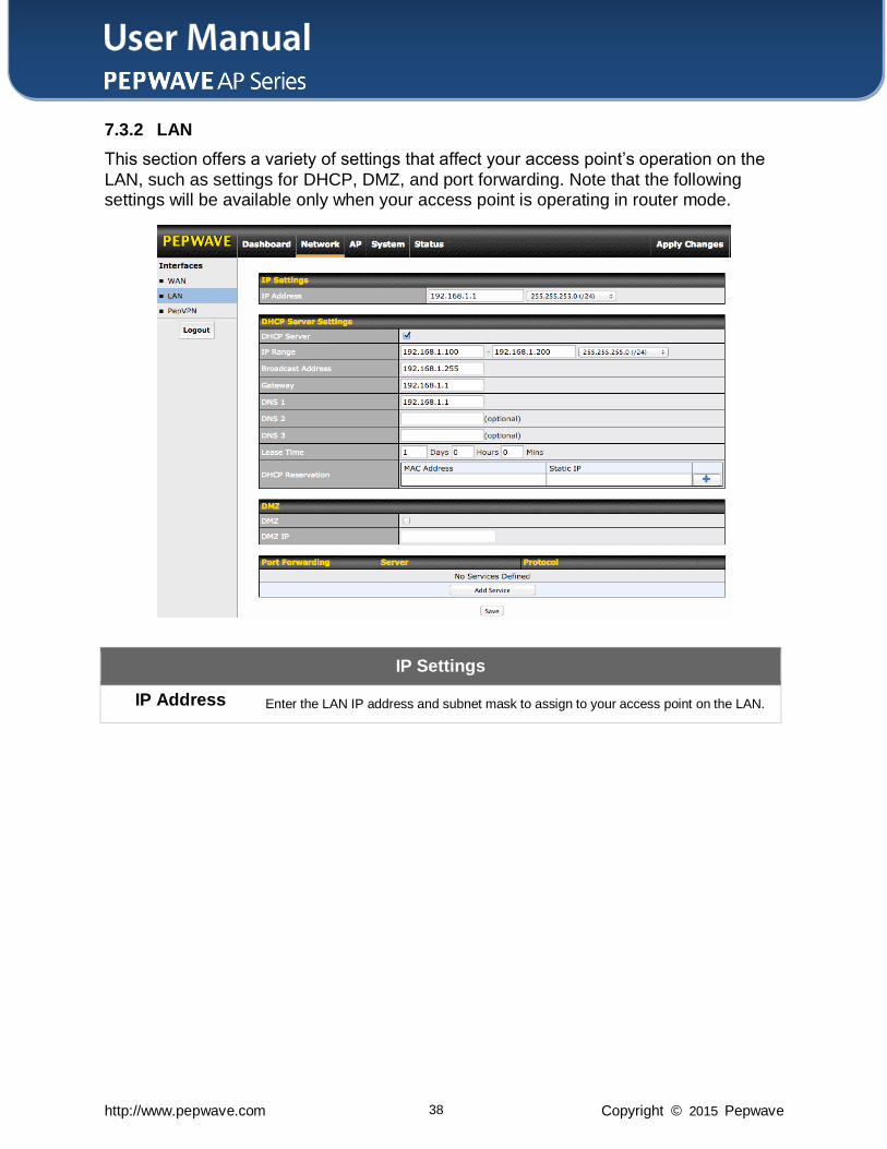
7.3.2 LAN
This section offers a variety of settings that affect your access point’s operation on the
LAN, such as settings for DHCP, DMZ, and port forwarding. Note that the following settings will be available only when your access point is operating in router mode.
IP Settings
IP Address Enter the LAN IP address and subnet mask to assign to your access point on the LAN.
User Manual
http://www.pepwave.com 39 Copyright © 2015 Pepwave
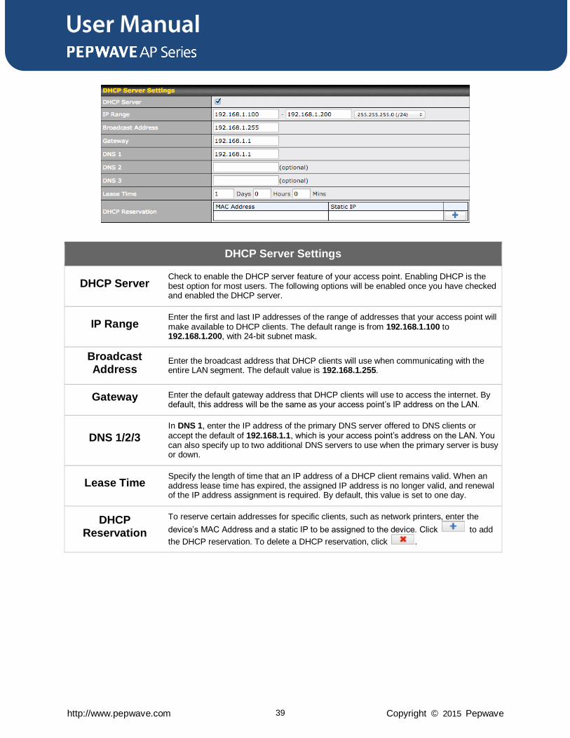
DHCP Server Settings
DHCP Server Check to enable the DHCP server feature of your access point. Enabling DHCP is the best option for most users. The following options will be enabled once you have checked and enabled the DHCP server.
IP Range Enter the first and last IP addresses of the range of addresses that your access point will make available to DHCP clients. The default range is from 192.168.1.100 to 192.168.1.200, with 24-bit subnet mask.
Broadcast Address
Enter the broadcast address that DHCP clients will use when communicating with the entire LAN segment. The default value is 192.168.1.255.
Gateway Enter the default gateway address that DHCP clients will use to access the internet. By default, this address will be the same as your access point’s IP address on the LAN.
DNS 1/2/3 In DNS 1, enter the IP address of the primary DNS server offered to DNS clients or accept the default of 192.168.1.1, which is your access point’s address on the LAN. You can also specify up to two additional DNS servers to use when the primary server is busy or down.
Lease Time Specify the length of time that an IP address of a DHCP client remains valid. When an address lease time has expired, the assigned IP address is no longer valid, and renewal of the IP address assignment is required. By default, this value is set to one day.
DHCP Reservation
To reserve certain addresses for specific clients, such as network printers, enter the
device’s MAC Address and a static IP to be assigned to the device. Click to add
the DHCP reservation. To delete a DHCP reservation, click .
User Manual
http://www.pepwave.com 40 Copyright © 2015 Pepwave
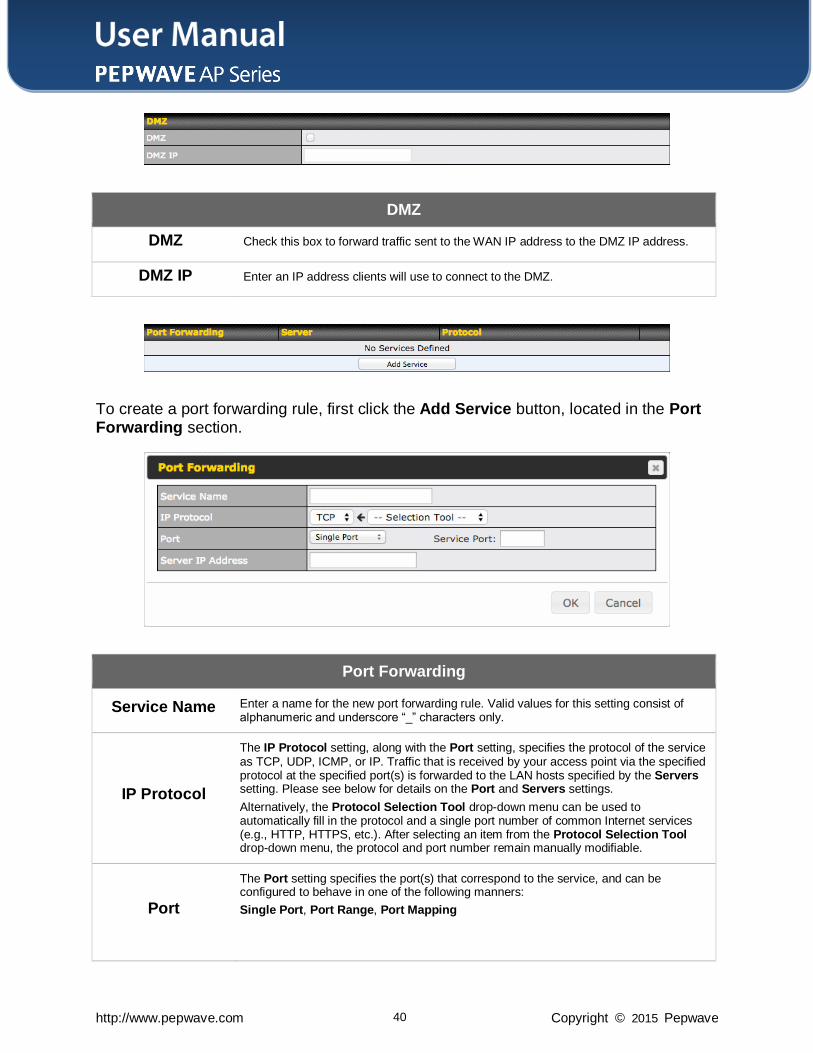
DMZ
DMZ Check this box to forward traffic sent to the WAN IP address to the DMZ IP address.
DMZ IP Enter an IP address clients will use to connect to the DMZ.
To create a port forwarding rule, first click the Add Service button, located in the Port Forwarding section.
Port Forwarding
Service Name Enter a name for the new port forwarding rule. Valid values for this setting consist of alphanumeric and underscore “_” characters only.
IP Protocol
The IP Protocol setting, along with the Port setting, specifies the protocol of the service as TCP, UDP, ICMP, or IP. Traffic that is received by your access point via the specified protocol at the specified port(s) is forwarded to the LAN hosts specified by the Servers setting. Please see below for details on the Port and Servers settings.
Alternatively, the Protocol Selection Tool drop-down menu can be used to automatically fill in the protocol and a single port number of common Internet services (e.g., HTTP, HTTPS, etc.). After selecting an item from the Protocol Selection Tool drop-down menu, the protocol and port number remain manually modifiable.
Port
The Port setting specifies the port(s) that correspond to the service, and can be configured to behave in one of the following manners:
Single Port, Port Range, Port Mapping
User Manual
http://www.pepwave.com 41 Copyright © 2015 Pepwave
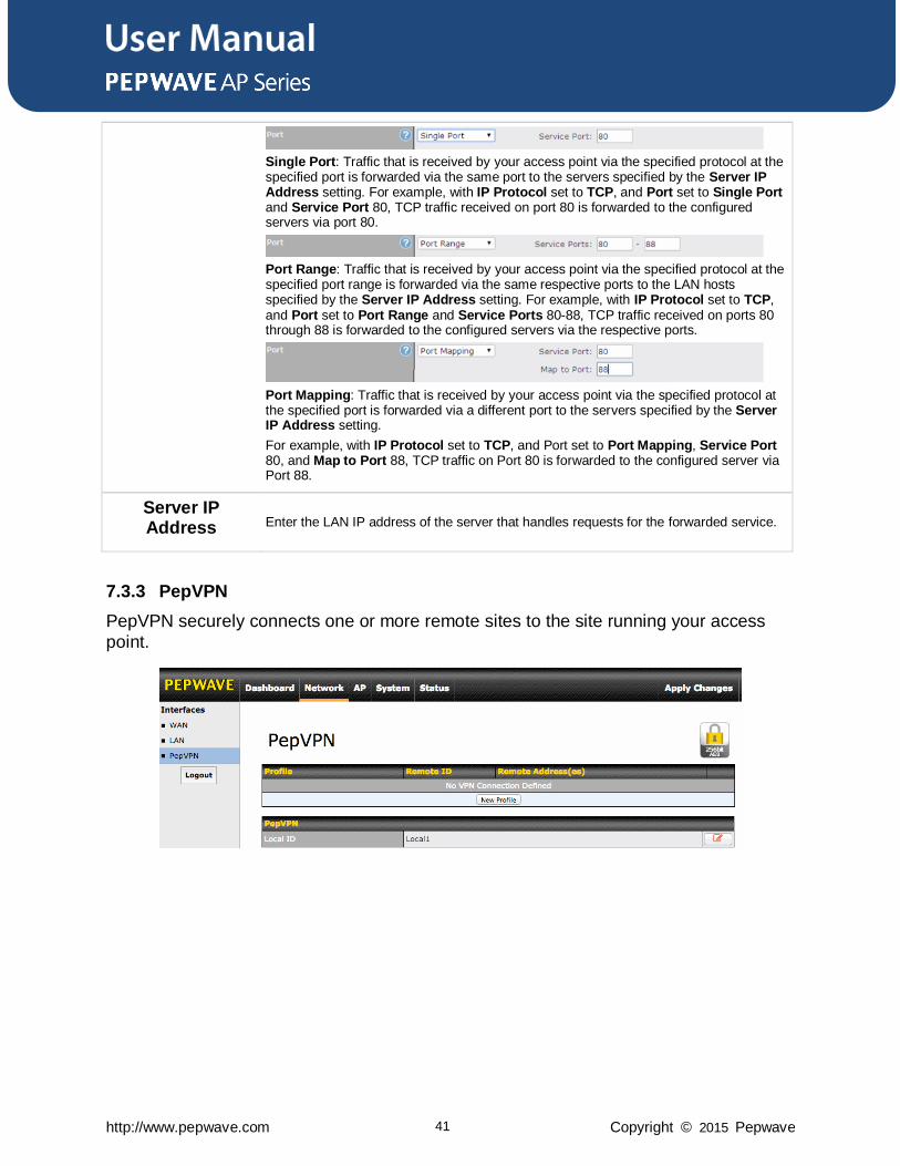
Single Port: Traffic that is received by your access point via the specified protocol at the specified port is forwarded via the same port to the servers specified by the Server IP Address setting. For example, with IP Protocol set to TCP, and Port set to Single Port and Service Port 80, TCP traffic received on port 80 is forwarded to the configured servers via port 80.
Port Range: Traffic that is received by your access point via the specified protocol at the specified port range is forwarded via the same respective ports to the LAN hosts specified by the Server IP Address setting. For example, with IP Protocol set to TCP, and Port set to Port Range and Service Ports 80-88, TCP traffic received on ports 80 through 88 is forwarded to the configured servers via the respective ports.
Port Mapping: Traffic that is received by your access point via the specified protocol at the specified port is forwarded via a different port to the servers specified by the Server IP Address setting.
For example, with IP Protocol set to TCP, and Port set to Port Mapping, Service Port 80, and Map to Port 88, TCP traffic on Port 80 is forwarded to the configured server via Port 88.
Server IP Address Enter the LAN IP address of the server that handles requests for the forwarded service.
7.3.3 PepVPN
PepVPN securely connects one or more remote sites to the site running your access
point.
User Manual
http://www.pepwave.com 42 Copyright © 2015 Pepwave
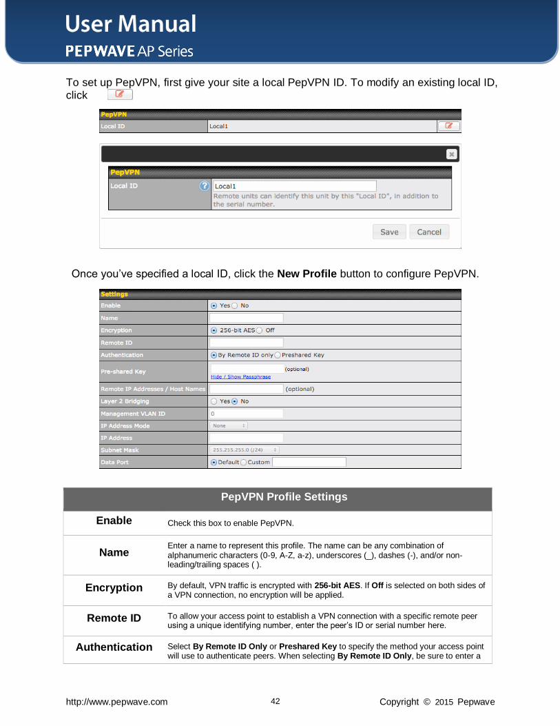
To set up PepVPN, first give your site a local PepVPN ID. To modify an existing local ID, click .
Once you’ve specified a local ID, click the New Profile button to configure PepVPN.
PepVPN Profile Settings
Enable Check this box to enable PepVPN.
Name Enter a name to represent this profile. The name can be any combination of alphanumeric characters (0-9, A-Z, a-z), underscores (_), dashes (-), and/or non-leading/trailing spaces ( ).
Encryption By default, VPN traffic is encrypted with 256-bit AES. If Off is selected on both sides of a VPN connection, no encryption will be applied.
Remote ID To allow your access point to establish a VPN connection with a specific remote peer using a unique identifying number, enter the peer’s ID or serial number here.
Authentication Select By Remote ID Only or Preshared Key to specify the method your access point will use to authenticate peers. When selecting By Remote ID Only, be sure to enter a
User Manual
http://www.pepwave.com 43 Copyright © 2015 Pepwave
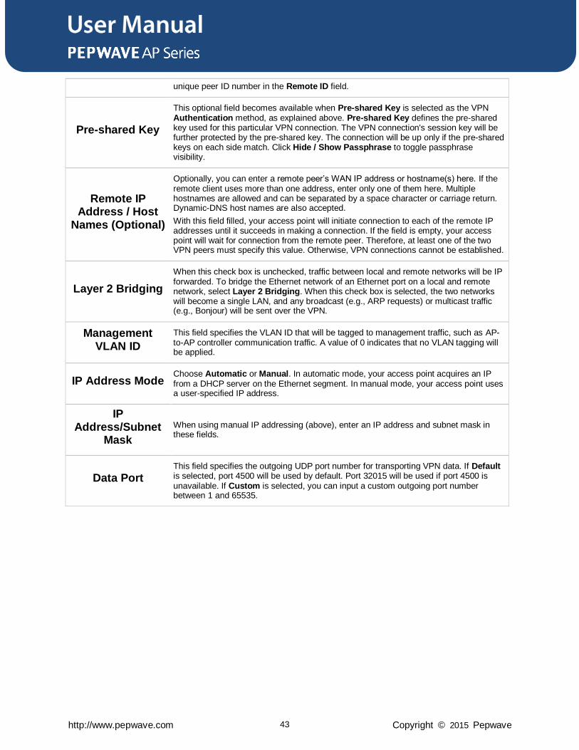
unique peer ID number in the Remote ID field.
Pre-shared Key
This optional field becomes available when Pre-shared Key is selected as the VPN Authentication method, as explained above. Pre-shared Key defines the pre-shared key used for this particular VPN connection. The VPN connection's session key will be further protected by the pre-shared key. The connection will be up only if the pre-shared keys on each side match. Click Hide / Show Passphrase to toggle passphrase visibility.
Remote IP Address / Host
Names (Optional)
Optionally, you can enter a remote peer’s WAN IP address or hostname(s) here. If the remote client uses more than one address, enter only one of them here. Multiple hostnames are allowed and can be separated by a space character or carriage return. Dynamic-DNS host names are also accepted.
With this field filled, your access point will initiate connection to each of the remote IP addresses until it succeeds in making a connection. If the field is empty, your access point will wait for connection from the remote peer. Therefore, at least one of the two VPN peers must specify this value. Otherwise, VPN connections cannot be established.
Layer 2 Bridging
When this check box is unchecked, traffic between local and remote networks will be IP forwarded. To bridge the Ethernet network of an Ethernet port on a local and remote network, select Layer 2 Bridging. When this check box is selected, the two networks will become a single LAN, and any broadcast (e.g., ARP requests) or multicast traffic (e.g., Bonjour) will be sent over the VPN.
Management VLAN ID
This field specifies the VLAN ID that will be tagged to management traffic, such as AP-to-AP controller communication traffic. A value of 0 indicates that no VLAN tagging will be applied.
IP Address Mode Choose Automatic or Manual. In automatic mode, your access point acquires an IP from a DHCP server on the Ethernet segment. In manual mode, your access point uses a user-specified IP address.
IP Address/Subnet
Mask
When using manual IP addressing (above), enter an IP address and subnet mask in these fields.
Data Port This field specifies the outgoing UDP port number for transporting VPN data. If Default is selected, port 4500 will be used by default. Port 32015 will be used if port 4500 is unavailable. If Custom is selected, you can input a custom outgoing port number between 1 and 65535.
User Manual
http://www.pepwave.com 44 Copyright © 2015 Pepwave
8 Tools
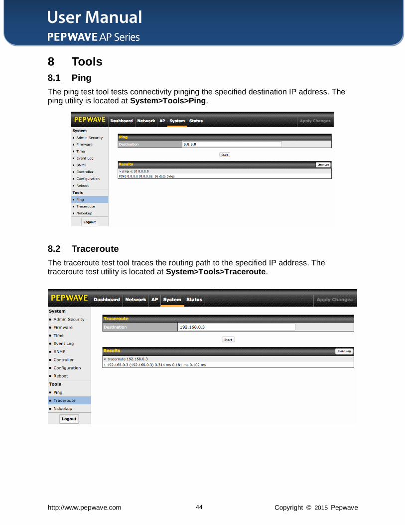
8.1 Ping
The ping test tool tests connectivity pinging the specified destination IP address. The ping utility is located at System>Tools>Ping.
8.2 Traceroute
The traceroute test tool traces the routing path to the specified IP address. The traceroute test utility is located at System>Tools>Traceroute.
User Manual
http://www.pepwave.com 45 Copyright © 2015 Pepwave
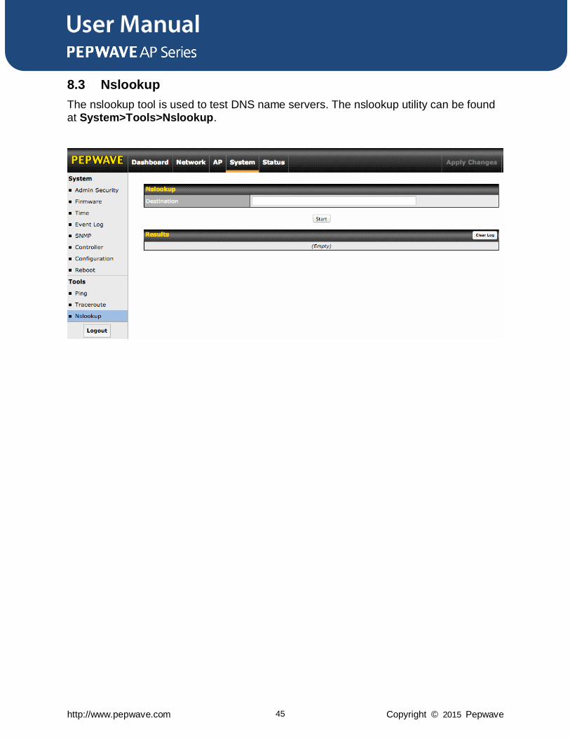
8.3 Nslookup
The nslookup tool is used to test DNS name servers. The nslookup utility can be found at System>Tools>Nslookup.
User Manual
http://www.pepwave.com 46 Copyright © 2015 Pepwave
9 Monitoring Device Status
The displays available on the Status tab help you monitor device data, client activity,
rogue device access, and more.
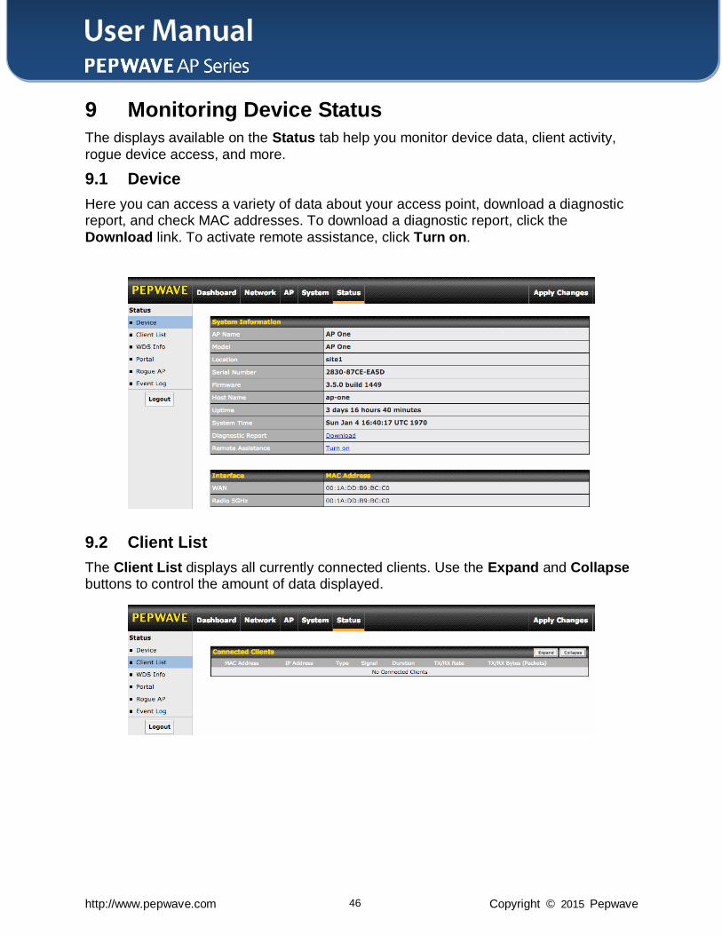
9.1 Device
Here you can access a variety of data about your access point, download a diagnostic report, and check MAC addresses. To download a diagnostic report, click the
Download link. To activate remote assistance, click Turn on.
9.2 Client List
The Client List displays all currently connected clients. Use the Expand and Collapse buttons to control the amount of data displayed.
User Manual
http://www.pepwave.com 47 Copyright © 2015 Pepwave
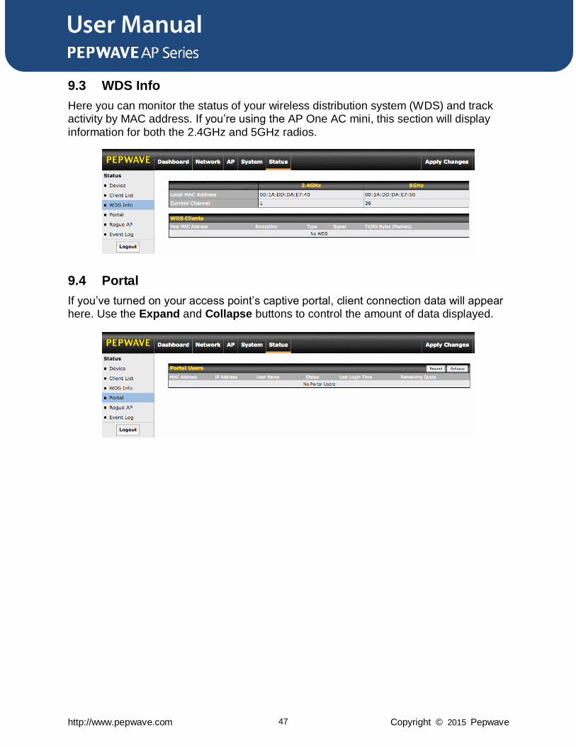
9.3 WDS Info
Here you can monitor the status of your wireless distribution system (WDS) and track activity by MAC address. If you’re using the AP One AC mini, this section will display
information for both the 2.4GHz and 5GHz radios.
9.4 Portal
If you’ve turned on your access point’s captive portal, client connection data will appear here. Use the Expand and Collapse buttons to control the amount of data displayed.
User Manual
http://www.pepwave.com 48 Copyright © 2015 Pepwave
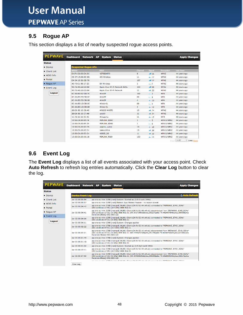
9.5 Rogue AP
This section displays a list of nearby suspected rogue access points.
9.6 Event Log
The Event Log displays a list of all events associated with your access point. Check Auto Refresh to refresh log entries automatically. Click the Clear Log button to clear
the log.
User Manual
http://www.pepwave.com 49 Copyright © 2015 Pepwave
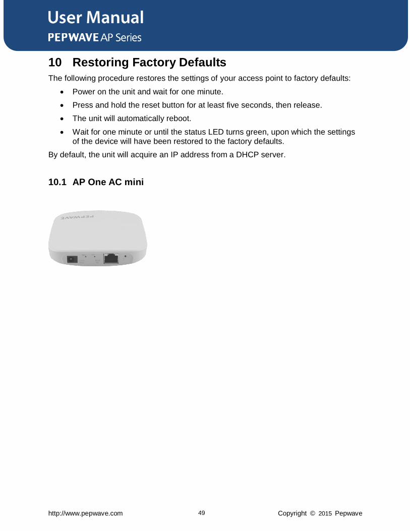
10 Restoring Factory Defaults
The following procedure restores the settings of your access point to factory defaults:
Power on the unit and wait for one minute.
Press and hold the reset button for at least five seconds, then release.
The unit will automatically reboot.
Wait for one minute or until the status LED turns green, upon which the settings of the device will have been restored to the factory defaults.
By default, the unit will acquire an IP address from a DHCP server.
10.1 AP One AC mini
User Manual
http://www.pepwave.com 50 Copyright © 2015 Pepwave
11 Appendix
Federal Communication Commission Interference Statement
This equipment has been tested and found to comply with the limits for a Class A digital device, pursuant to Part 15 of the FCC Rules. These limits are designed to provide reasonable protection against harmful interference in a residential installation. This
equipment generates, uses and can radiate radio frequency energy and, if not installed and used in accordance with the instructions, may cause harmful interference to radio communications. However, there is no guarantee that interference will not occur in a
particular installation. If this equipment does cause harmful interference to radio or television reception, which can be determined by turning the equipment off and on, the user is encouraged to try to correct the interference by one of the following measures:
1) Increase the separation between the equipment and receiver.
2) Connect the equipment into an outlet on a circuit different from that to which the receiver is connected.
3) Consult the dealer or an experienced radio/TV technician for help.
This device complies with Part 15 of the FCC Rules. Operation is subject to the following two conditions: (1) This device may not cause harmful interference, and (2)
this device must accept any interference received, including interference that may cause undesired operation.
FCC Caution: Any changes or modifications not expressly approved by the party
responsible for compliance could void the user's authority to operate this equipment.
IEEE 802.11b or 802.11g operation of this product in the U.S.A. is firmware-limited to channels 1 through 11.
IMPORTANT NOTE
FCC Radiation Exposure Statement
This equipment complies with FCC radiation exposure limits set forth for an uncontrolled environment. This equipment should be installed and operated with minimum distance
20cm between the radiator & your body.
This transmitter must not be co-located or operating in conjunction with any other antenna or transmitter.
The availability of some specific channels and/or operational frequency bands is country dependent and is firmware programmed at the factory to match the intended destination.

Contact Us:
Sales http://www.pepwave.com/contact/sales/
Support http://www.pepwave.com/contact/
Business Development and
Partnerships
http://www.pepwave.com/partners/channel-
partner-program/
Address:
Hong Kong Office
A5, 5/F, HKSIB Phase 6, 481 Castle Peak Road Cheung Sha Wan
Hong Kong Tel: +852 2990 7600
Fax: +852 3007 0588
www.pepwave.com
Related Documents