AnyMedia ® Access System (24 Channel) Optical Network Unit Installation Manual for Outdoor Applications Issue 1 June 2002 363-211-520

Welcome message from author
This document is posted to help you gain knowledge. Please leave a comment to let me know what you think about it! Share it to your friends and learn new things together.
Transcript

AnyMedia® Access System(24 Channel)Optical Network UnitInstallation Manual for Outdoor Applications
Issue 1June 2002
363-211-520
Copyright ©1998, 1999, 2000, 2001, 2002 Lucent Technologies All Rights Reserved
This material is protected by the copyright laws of the United States and other countries. It may not be reproduced, distributed or altered in any fashion by any entity, including other Lucent Technologies Inc. Business Units or Divisions, without the permission of Lucent Technologies Inc. For permission to reproduce or distribute, contact your local Lucent Technologies Inc. Account Executive.
NoticeEvery effort was made to ensure that the information in this document was complete and accurate at the time of printing. However, information is subject to change.
Federal Communications Commission (FCC)Notification and Repair Information1
NOTE: This equipment has been tested to comply with the limits for a Class A digital device, pursuant to Part 15 of the FCC Rules. These limits are designed to provide reasonable protection against harmful interference when the equipment is operated in a commercial environment. This equipment generates, uses, and can radiate radio frequency energy and, if not installed and used in accordance with the instructions manual, may cause interference to radio communications. Operation of this equipment in a residence is likely to cause harmful interference in which case the user will be required to correct the interference at his own expense.
SecurityIn rare instances, unauthorized individuals make connections to the telecommunications network. In such event, applicable tariffs require that the customer pay all network charges for traffic. Lucent Technologies Inc. cannot be responsible for such charges and will not make any allowance or give any credit for charges that result from unauthorized access.
Document Ordering InformationThe ordering number for this document is 363-211-520. To order this document call 1-888-LUCENT8. RBOC/BOC customers should process document orders or standing document orders through their Company Documentation Coordinator. For more ordering information, refer to “How to Order Documents” in the section “About This Document.”
How to Comment on This DocumentA feedback form is located immediately after the trademarks page of this document. Please send or fax your comments and suggestions to:
ATTENTION: Lucent TechnologiesAttn: Customer Documentation CoordinatorRoom 14D-311PO Box 90367 Whippany RoadWhippany, NJ 07981-0903
Fax (973) 581-6646
1. Language of Statute

Trademarks4TEL is a registered trademark of Teradyne, Inc.
5ESS is a registered trademark of Lucent Technologies
ACCUNET is a service mark of AT&T
Acrobat is a registered trademark of Adobe Systems Incorporated
Adobe is a registered trademark of Adobe Systems Incorporated
ANSI is a registered trademark of American National Standards Institute, Inc.
AnyMedia is a registered trademark of Lucent Technologies
Business OfficeXchange and BOX are trademarks of VINA Technologies, Inc.
CLASS is a service mark of Telcordia Technologies, Inc.
ClearReach is a trademark of Lucent Technologies
Common Language is a registered trademark and CLEI, CLLI, CLCI, and CLFI are trademarks of Telcordia Technologies, Inc.
ConnectReach and ConnectReach Plus are trademarks of Lucent Technologies
Datapath is a trademark of CAE Electronics
DMS is a trademark of Nortel Networks
EWSD is a registered trademark of Siemens
FAST is a trademark of Lucent Technologies
ForeRunner is a registered trademark of Fore Systems, Inc.
HiGain is a registered trademark of PairGain Technologies, Inc.
Internet Explorer is a copyright of Microsoft Corporation
LGX is a registered trademark of Lucent Technologies
LINEAGE is a registered trademark of Lucent Technologies
Local Call Routing and LCR are trademarks of VINA Technologies, Inc.
LoopCare is a trademark of Tollgrade Communications, Inc.
MainStreetXpress is a trademark of Newbridge Networks Corporation
MCU is a registered trademark of Tollgrade Communications, Inc.
Micro-Bank is a registered trademark of Tollgrade Communications, Inc.
Navis is a trademark of Lucent Technologies
Netscape Navigator is a trademark of Netscape Communications Corporation
NGRTH is a trademark of General Signal Corporation
NMA is a registered trademark of Telcordia Technologies, Inc.
PacketStar is a trademark of Lucent Technologies
PairGain is a registered trademark of PairGain Technologies, Inc.
SLC is a registered trademark of Lucent Technologies
Solitare is a trademark of PairGain Technologies, Inc.
SPOTS is a registered trademark of Lucent Technologies
SPQ is a registered trademark of Lucent Technologies

SWITCH is a registered trademark of Telcordia Technologies, Inc.
Tau-Tron is a registered trademark of General Signal Corporation
Telcordia is a trademark of Telcordia Technologies, Inc.
TIRKS is a registered trademark of Telcordia Technologies, Inc.
Tollgrade is a registered trademark of Tollgrade Communications, Inc.
Total Reach is a registered trademark of ADTRAN, Inc.
UL is a registered trademark of Underwriters Laboratories, Inc.
UNIX is a registered trademark in the United States and other countries, licensed exclusively through X/Open Company Limited
US Sprint is a registered trademark of US Sprint Communications Company Limited
Windows is a trademark of Microsoft Corporation
Windows 95, Windows 98, and Windows 2000 are copyrights of Microsoft Corporation
Windows NT is a registered trademark of Microsoft Corporation
WordPad is a copyright of Microsoft Corporation
Quality Management SystemThe Quality Management System (QMS) for Lucent Technologies’ AnyMedia® Access Systems R&D organizations has been registered to IS0 9001 under the Norwegian Scheme by Det Norske Veritas (DNV) since June 1993. ISO 9001 is an international quality standard recognized by more than 90 countries worldwide. It is a model for quality assurance in design, development, production, installation, and servicing.
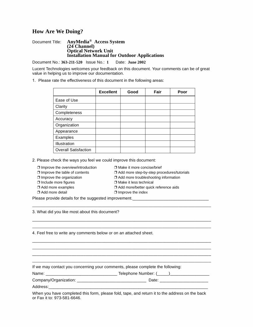
How Are We Doing?
Document Title: AnyMedia® Access System(24 Channel)Optical Network UnitInstallation Manual for Outdoor Applications
Document No.: 363-211-520 Issue No.: 1 Date: June 2002Lucent Technologies welcomes your feedback on this document. Your comments can be of great value in helping us to improve our documentation.
Please rate the effectiveness of this document in the following areas:
Please check the ways you feel we could improve this document:
Improve the overview/introduction Make it more concise/brief Improve the table of contents Add more step-by-step procedures/tutorials Improve the organization Add more troubleshooting information Include more figures Make it less technical Add more examples Add more/better quick reference aids Add more detail Improve the index
Please provide details for the suggested improvement._________________________________
What did you like most about this document?
Feel free to write any comments below or on an attached sheet.
If we may contact you concerning your comments, please complete the following:Name: _______________________________ Telephone Number: (_____)_________________Company/Organization: ______________________________ Date: _____________________Address:_____________________________________________________________________When you have completed this form, please fold, tape, and return it to the address on the backor Fax it to: 973-581-6646.
Excellent Good Fair Poor
Ease of UseClarityCompletenessAccuracyOrganizationAppearanceExamplesIllustrationOverall Satisfaction

BUSINESS REPLY MAILFIRST CLASS PERMIT NO. 5, NEW PROVIDENCE, NJ
POSTAGE WILL BE PAID BY ADDRESSEE
------------------------------------------------------------------- Do Not Cut — Fold Here And Tape --------------------------------------------------------------
!"
#$$ %&'"
()*##+
*##+,-')&.!'&'"
363-211-520Table of Contents
Table of Contents
About This Manual Introduction xvii Conventions Used in This Document xx Related Documentation xxii How to Order this Document xxiv How to comment on this document xxv
1 Safety Overview 1-1 Electrostatic Discharge 1-3 Battery Safety 1-6 Special Considerations for the Tyco IR-40EC Batteries 1-8 General Safety Admonishments 1-9 Electrical Wiring Admonishments 1-11
2 ONU Product Description Overview 2-1 Principal ONU Components 2-2
3 Overview of the Installation Process Overview 3-1 Installation Sequence 3-2 Tools and Measurement /Testing Instruments 3-4
4 Site Ground for Pedestal Mounted ONUs Overview 4-1 Site Ground Requirements 4-2 Recommended Connections 4-3
AnyMedia ONU Installation Manual: Outdoor, Issue 1 June 2002 vii

363-211-520Table of Contents
5 Mounting the ONU Overview 5-1 Mounting and Installing the Optional Cross-Connect 5-3 Pedestal Mount 5-17 Wall Mount 5-20 Pole Mount 5-24
6 Installing and Grounding External Cables Overview 6-1 Cabling Overview 6-3 Routing Cables for Pedestal-Mounted ONUs 6-4 Routing Cables for Wall- and Pole-Mounted ONU 6-8 Connecting to the Site Ground 6-10 Grounding Subscriber Line Connections 6-13 Grounding the AC Power Cable 6-17 Checking the Ground Connections 6-18 Sealing and Caulking the ONU Cables 6-19
7 Connecting the Signal Lines Overview 7-1 Signal Cabling and Wiring Overview 7-3 ONU Cable Reference 7-5 Cable Installation and Wiring Procedures 7-13 Wiring of Connectors and Connecting Points of the ONU shelf 7-23 Installing the Fiber 7-25
8 Connecting AC Power Overview 8-1 AC Power Supply Service 8-2 Connecting to the AC Utility 8-4
viii June 2002 AnyMedia ONU Installation Manual: Outdoor, Issue 1
363-211-520Table of Contents
9 Installing the Batteries Overview 9-1 Battery Option 9-3 Battery Safety 9-5 Battery Handling and Preparation 9-7 Installing the Batteries 9-13
10 System Power Up Overview 10-1 Installing the Power and Ringing Modules 10-3 Installing the PRU 10-5 Installing the LVD 10-7 Installing the Optional RGU 10-9 Applying AC Power 10-11 Checking the Rectifier and Batteries 10-13 Connecting and Charging the Batteries 10-16
11 Fan Unit and Battery Maintenance Overview 11-1 Maintenance Intervals 11-3 Maintenance of the Fan Units 11-4 Battery Maintenance Practice 11-14 Battery Maintenance Procedures 11-16 Battery String Float Voltage 11-18 Battery Compartment Maintenance 11-23 Battery Replacement 11-25
AnyMedia ONU Installation Manual: Outdoor, Issue 1 June 2002 ix
363-211-520Table of Contents
A Installation and Maintenance Record Installation and Maintenance Record A-1
List of Acronyms
Glossary
Index
x June 2002 AnyMedia ONU Installation Manual: Outdoor, Issue 1
363-211-520List of Figures
List of Figures
1 Safety Figure 1-1 ESD Strap 1-4
2 ONU Product Description Figure 2-1 Equipped outdoor ONU (front view) 2-3 Figure 2-2 Side views of an equipped outdoor ONU (door open/cover
removed) 2-4
4 Site Ground for Pedestal Mounted ONUs Figure 4-1 Grounding requirements for the ONU for outdoor installation 4-3 Figure 4-2 Grounding requirements for a multiple ONU installation 4-4
5 Mounting the ONU Figure 5-1 Mounting points for the cross-connect configurations 5-4 Figure 5-2 Cross-connect, cable routing/wiring for xDSL-only
installations or the feeder side of combined POTS/xDSL installations 5-5 Figure 5-3 Krone cross-connect ED7C851-56 Gr.1 for POTS/xDSL
applications, feeder side 5-6 Figure 5-4 Krone cross-connect ED7C851-56 Gr.2 for POTS/xDSL
applications; distribution (right-hand) side 5-7 Figure 5-5 Cross-connect for xDSL-only applications 5-9 Figure 5-6 Cable routing inside the outdoor termination compartment 5-13 Figure 5-7 ONU shelf cabling arrangement 5-14 Figure 5-8 Cabling inside the electronics compartment 5-15 Figure 5-9 Typical cable arrangement in the pad cable entrance area 5-17 Figure 5-10 ONU Pedestal 5-18 Figure 5-11 Wall-mount bracket 5-21 Figure 5-12 Placing the ONU housing on the wall-mount bracket 5-22 Figure 5-13 Pole-mount brackets mounted 5-25 Figure 5-14 Reference dimensions for the ONU housing mounted to
the pole 5-26 Figure 5-15 Bolt and pole-mount bracket position for different poles 5-27 Figure 5-16 Placing the ONU housing onto the pole 5-28
ONU Installation Manual: Outdoor, Issue 1 June 2002 xi
363-211-520List of Figures
6 Installing and Grounding External Cables Figure 6-1 Termination compartment with cables installed
(pedestal-mounting shown) 6-3 Figure 6-2 Cable entrance area in the termination compartment 6-5 Figure 6-3 Installing the rubber cable seals 6-6 Figure 6-4 Set of parts for grounding the ONU 6-12 Figure 6-5 Bonding the cable sheath 6-13 Figure 6-6 Grounding kit with cable shield connectors for fiber cables 6-14 Figure 6-7 Removal of the sheath and placing the pair protector 6-15 Figure 6-8 Mounting the fiber in the split bolt 6-15 Figure 6-9 Cables inserted and grounded 6-19 Figure 6-10 Cable entrance ports (shown with seals and grommets
installed) 6-20
7 Connecting the Signal Lines Figure 7-1 Cable routing inside the termination compartment
(cross-connect for POTS and xDSL shown) 7-6 Figure 7-2 ONU shelf cabling arrangement 7-7 Figure 7-3 Internal ONU cabling inside the electronics compartment 7-8 Figure 7-4 Connector and cable positions of the pre-installed cabling
inside the electronics compartment 7-9 Figure 7-5 Cable positions of the pre-installed (except as noted) cabling
inside the termination compartment 7-10 Figure 7-6 ONU backplane arrangement as viewed from the front
(no pack inserted) 7-14 Figure 7-7 DIP switch for ONU addressing 7-15 Figure 7-8 Cabling for integrated testing with TAP100 inserted in slot
position AP-8 as an example 7-17 Figure 7-9 Principle for rerouting POTS over ADSL 7-22 Figure 7-10 Pack Arrangement and Connector Arrangement of the
ONU shelf 7-23 Figure 7-11 Connector Arrangement of the ONU Shelf Connection
Panel (SCP) 7-24
8 Connecting AC Power Figure 8-1 AC routing from AC utility and grounding 8-2 Figure 8-2 AC connection variants 8-6
xii June 2002 ONU Installation Manual: Outdoor, Issue 1
363-211-520List of Figures
9 Installing the Batteries Figure 9-1 IR-40EC battery 9-4 Figure 9-2 Example for a cardboard box with “charge no later than” date 9-8 Figure 9-3 Copy of the initial charging recommendation of IR-40EC
batteries 9-9 Figure 9-4 Battery labels showing the battery serial number and
installation date 9-11 Figure 9-5 Empty battery compartment (battery hold down bracket
removed) 9-13 Figure 9-6 Outdoor application battery arrangement (only the 14 AWG
lead assembly shown) 9-14 Figure 9-7 Position of the ring-type thermal probe 9-16 Figure 9-8 Mounted batteries (Batteries 1 and 2 already inserted; Batteries
No. 4 and No. 5 to be inserted) 9-16
10 System Power Up Figure 10-1 ONU with LVD, PRU, and RGU 10-3 Figure 10-2 Position of the Margin switch 10-5 Figure 10-3 LVD Faceplate 10-7 Figure 10-4 Location and settings of the jumpers MP1/MP2 on the RGU 10-10 Figure 10-5 Temperature compensation of charging voltage (typical) 10-13 Figure 10-6 Rectifier voltage operation characteristic (typical) 10-14 Figure 10-7 Wiring of connector J3 for the LVD and wiring of battery
cable connector J3 10-15
11 Fan Unit and Battery Maintenance Figure 11-1 Heat exchanger side of the ONU 11-4 Figure 11-2 Ambient fan mounting points 11-5 Figure 11-3 Ambient fan removed 11-7 Figure 11-4 Cabinet fan unit 11-8 Figure 11-5 Battery fan unit and battery compartment 11-10 Figure 11-6 Battery arrangement 11-11 Figure 11-7 Position of the ring-type thermal probe 11-11 Figure 11-8 Mounted batteries (batteries No. 1 and No. 2 already
inserted, batteries No. 4 and No. 5 have to be inserted) 11-12 Figure 11-9 Wiring of battery cable connector J3 11-19 Figure 11-10 Wiring of the 14 AWG lead battery assembly connectors 11-21
ONU Installation Manual: Outdoor, Issue 1 June 2002 xiii
363-211-520List of Figures
xiv June 2002 ONU Installation Manual: Outdoor, Issue 1
363-211-520 !"
List of Tables
3 Overview of the Installation Process Table 3-1. List of tools and equipment 3-4
5 Mounting the ONU Table 5-1. Connections to the MDF (example), external cable 848569257
from ONU shelf, TAP-B connector to the cross-connect 5-12
7 Connecting the Signal Lines Table 7-1. ONU Cable connections 7-11 Table 7-2. Cross-connections for TAP-B cable 848569257 and the
TAP100 (example for TAP100 inserted in AP8) 7-18 Table 7-3. Optical link parameters 7-26 Table 7-4. Delivered fiber cable for the ONU Shelf 7-28
9 Installing the Batteries Table 9-1. Delivered battery set 9-3
10 System Power Up Table 10-1. Module Codes 10-4 Table 10-2. Margin switch charging adjustments 10-6 Table 10-3. Input operating specification of the PRU 10-16 Table 10-4. Output specification of the PRU 10-17
11 Fan Unit and Battery Maintenance Table 11-1. Required maintenance intervals for IR-40EC batteries 11-16 Table 11-2. Suggested maintenance routines (additional) 11-17
AnyMedia ONU Installation Manual: Outdoor, Issue 1 June 2002 xv

363-211-520List of Tables
xvi June 2002 AnyMedia ONU Installation Manual: Outdoor, Issue 1
AnyMedia ONU Installation Manual: Outdoor, Issue 1
About This Manual 0
Introduction 0
Purpose This Installation Manual (IM) provides installation instructions for Lucent Technologies’ AnyMedia Optical Network Unit (ONU) for outdoor applications. The system is available in three configurations:
Wall-mounted,
Pole-mounted,
Pedestal-mounted.
Another model of the ONU is available for indoor applications, but is not discussed in this manual. If you are interested in obtaining more information on the ONU for indoor applications, contact your Lucent Technologies representative.
Scope The ONU IM is intended to enable installation personnel to install the AnyMedia ONU. In principal, the ONU will be delivered with all passive system components and with all internal cabling pre-installed, including the cabling from the APs of the ONU shelf to the feeder side of the internal MDF. The installer has mainly to perform the connections from and to the ONU (AC, fiber, and distribution side of the MDF). Installation of the application packs and turn-up are performed after the installation procedures described in this manual are complete.
Intended audience This installation manual is for technical support personnel and for customers who maintain their own installation organizations.
June 2002 xvii
Introduction363-211-520
About This Manual
Reason for issue This is Issue 1 of the Installation Manual.
How to use this manual
This manual is organized as follows:
How are we doing
A comment form so readers can give feedback to improve the next revision of the document.
Table of contents, list of figures, list of tables.
About This Manual
This chapter defines the purpose of the document and the intended audience. Also included are topics about the conventions used in the document, related documentation, how to order documents, and how to comment on this document.
Safety
This chapter defines the types of safety labels and precautions associated with the AnyMedia Access System. Also included are general circuit pack handling precautions and specific warnings relating to lightwave safety, ESD considerations, handling batteries, connecting to AC utility, and other built-in equipment.
ONU Product Description
This chapter describes principal components that comprise the outdoor AnyMedia ONU.
Overview of the Installation Process
This chapter summarizes the ONU installation and cabling process and lists the tools and test instruments you will need to accomplish the installation.
Site Ground for Pedestal Mounted ONUs
This chapter addresses the site grounding requirements and recommended connections for a pedestal-mounted ONU. This chapter does not apply to pole-mounted or wall-mounted ONUs.
Mounting the ONU
This chapter describes the procedures for mounting the cross-connects in the ONU termination compartment; for mounting/installing the ONU; and for connecting it to the site ground. These mounting procedures must be performed before you connect any external cables to the ONU or power-up the system.
Installing and Grounding External Cables
This section describes the procedures for installing and grounding the signal and power cables required by the ONU.
xviii June 2002 AnyMedia ONU Installation Manual: Outdoor, Issue 1
363-211-520IntroductionAbout This Manual
Connecting the Signal Lines
This chapter provides the procedures for installing the ONU copper and fiber signal cables.
Connecting AC Power
This chapter describes the requirements and procedures for connecting the ONU to the local electric utility.
Installing the Batteries
This section provides the procedures for unpacking, inspecting, and mounting the batteries in the ONU battery compartment.
System Power Up
This chapter provides the procedures for installing power-related modules, applying AC power and activating the batteries.
Fan Unit and Battery Maintenance
This chapter covers the recommended maintenance procedures for the AnyMedia ONU fan units and batteries.
Appendix A: Installation and Maintenance Record
This appendix contains a copy of the installation and maintenance record.
List of Acronyms
Lists the abbreviations and acronyms used to replace longer expressions.
Glossary
Defines terms that may be unfamiliar to the user.
Index
Lists in alphabetical order the specific subject information in the document.
AnyMedia ONU Installation Manual: Outdoor, Issue 1 June 2002 xix
Conventions Used in This Document363-211-520
About This Manual
Conventions Used in This Document 0
Terms used The following terms used in this manual may have different meanings than the general or common usages of the term.
The term AnyMedia Access System is used here for both the AnyMedia FAST shelf and for the AnyMedia ONU subshelf.
The term system configuration when used here refers to an AnyMedia Access System system equipped with certain packs or units for a certain application.
Mixed configuration means a configuration of the AnyMedia Access System that includes packs for narrowband and AFM xDSL services.
The term AnyMedia FAST shelf is used when the text refers to the shelf which houses the COMDAC, CTU, OAP, and AFM pack.
The term ONU shelf is used when the text refers to the shelf in the ONU (housing the OCP) that provides the interface for the optical link to the AnyMedia FAST shelf.
The term AnyMedia shelves is used whenever the text does not need to distinguish between both types of shelves.
Narrowband services typically include POTS services, coin, special services such as foreign exchange and PBX support. In the current release of the AnyMedia Access System, narrowband services comprise POTS, COIN, PBX support, ISDN services, and high bit-rate digital subscriber lines (HDSL).
ATM xDSL services are supported in the AnyMedia Access System using ATM cell transfer. In the current release of the AnyMedia Access System, ATM xDSL services include ADSL, SDSL, and SHDSL.
The term pack is generally used for circuit packs in the AnyMedia FAST shelf (COMDAC and AFM) or in the ONU shelf (OCP, RGU, PRU, PFU and LVD), and also for all application packs.
The term application pack is generally used for the packs in the AnyMedia FAST shelf and also in the ONU shelf that are located in any of the AP slots of the AnyMedia Access System (APs for POTS, ISDN, and ATM xDSL).
In this manual the subscriber interface for analog POTS is tip/ring (T/R) interface.
DS1 interface refers to the 1.544-kbps digital feeder interfaces of the narrowband system on the network side of the AnyMedia FAST shelf.
DS3 interface refers to the digital feeder interface of the broadband system that carries the ATM payload cells. The DS3 interface is provided by the ATM feeder multiplexer AFMDS3.
DS3 interface refers to a bit rate of 44.736 MBps and a framing according to ITU-T recommendations G.804, I.432 and ANSI T1.107, without specifying the physical interface.
xx June 2002 AnyMedia ONU Installation Manual: Outdoor, Issue 1
363-211-520Conventions Used in This DocumentAbout This Manual
The term DSX-3 interface refers in the AnyMedia FAST shelf only to everything that DS3 refers to with the addition of a specific physical interface according to Telcordia standard GR-499.
ADSL line refers to the twisted copper pair carrying ATM xDSL services.
xDSL service means any broadband service transmitted over twisted pairs. Examples are ADSL, SDSL, and SHDSL.
ADSL modem means the ADSL data circuit-terminating equipment at the customer’s site.
The AnyMedia graphical system interface software (GSI) provides one graphical user interface for narrowband and ATM xDSL services to one AnyMedia Access System.
TL1 system interface (TL1SI) means any interface for operations using TL1 commands.
A trademark is not treated as an acronym (it is not spelled out or expanded).
Acronyms and abbreviations
In the text, acronyms are expanded the first time they are used in the main text of a chapter (e.g., permanent leased line [PLL]). (See List of Acronyms at the end of this document.) Trademarked acronyms are not spelled out.
Trademarks The trademarks used in this document are identified after the title page. Trademarks are in italics and modify a noun. Lucent Technologies trademarks are identified with the registered mark (®) or trademark symbol (™) the first time they are used in a chapter (e.g., Lucent Technologies AnyMedia® Access System). The trademarks of other companies are in italics.
AnyMedia ONU Installation Manual: Outdoor, Issue 1 June 2002 xxi
Related Documentation363-211-520
About This Manual
Related Documentation 0
Document list, packaging, and formats
The following documentation is available for the AnyMedia Access System:
Available on the Web 0 AnyMedia Access System Documents
— 363-211-125, AnyMedia® Access System, Ordering Guidehttp://www.lucent8.com/library/AnyMediaOrderingGuide.pdf.
— Other AnyMedia Access System documents, including System Release Descriptions (SRDs) and the Navis™ AnyMedia Element Management System (EMS), can be found by going to http://www.lucent8.com, selecting “Documents”, then selecting “Product Line: AnyMedia” (under “Enter 1 or more search items below”) and “Search Now”.
#$"%&"''"!""#%%"(' ")"$#(#!*)"*+
",)","'"!""
Available on CD-ROM 0
363-211-103, AnyMedia® Access System, Documentation. This is a CD-ROM that contains the following documents in various formats:
AnyMedia Access System Documents
— 363-211-101, AnyMedia® Access System, Applications, Planning, and Ordering Guide (APOG) (in PDF format)
— 363-211-125, AnyMedia® Access System, Ordering Guide (in PDF format)
— 363-211-106, AnyMedia® Access System, Feature Supplement—MDS2 Shelf Configurations (in PDF format)
— 363-211-127, AnyMedia® Access System, Feature Supplement—Integrated Access Terminal (in PDF format)
— 363-211-128, AnyMedia® Access System, Feature Supplement—Central Office Terminal (in PDF format)
— 363-211-102, AnyMedia® Access System, Installation Manual (in PDF format)
— 363-211-100, AnyMedia® Access System, Commands and Procedures (in HTML format, also includes PDFs of selected procedures)
— 363-211-129, AnyMedia® Access System, ConnectReach™ Terminal User’s Guide (in PDF format)
— 363-211-130, AnyMedia® Access System, ConnectReach Plus™ Terminal User’s Guide (in PDF format)
— 363-211-521, AnyMedia® Access System, Optical Network Unit Installation Manual for Indoor Application (in PDF format)
— 363-211-520, AnyMedia® Access System, Optical Network Unit Installation Manual for Outdoor Application (in PDF format)
xxii June 2002 AnyMedia ONU Installation Manual: Outdoor, Issue 1
363-211-520Related DocumentationAbout This Manual
SLC® Documents
— 363-205-121, SLC Series 5 Carrier System J1C182BC-1 Remote Terminal Ring Shelf, User Manual (in PDF format)
NOTE:An Adobe Acrobat Reader is provided to view all PDF files.For documents in HTML format, users need and must supply their own Web browser to view them. The documentation has been verified using the following Web browsers: Netscape Navigator 4.0 and Internet Explorer 5.0 or later.
The AnyMedia Access System Management Interface, which includes the graphical system interface (GSI) and the Network Maintenance Manager, is available on CD-ROM. To order, see the AnyMedia Access System Ordering Guide, 363-211-125.
AnyMedia ONU Installation Manual: Outdoor, Issue 1 June 2002 xxiii
How to Order this Document363-211-520
About This Manual
How to Order this Document 0
Order number The ordering number for the AnyMedia ONU Installation Manual for Outdoor Applications, Release 1, is 363-211-520.
Order procedure To order additional hard copies of this document and/or to request placement on the standing order list, send or call in an order as follows:
One time order One-time orders include the contents for the current document issue in effect at the time of order.
Standing order You may request an update on the standing order list for all later reissues of any document. The standing order list for each document provides automatic distribution for all reissues of the document.
Mail ordera Telephone order(Monday through Friday)
Lucent TechnologiesCustomer Information Center2855 N. Franklin Road P.O. Box 19901Indianapolis, IN 46219
Within USA: 1-888-LUCENT8b 7:30 a.m. to 6:30 p.m. EST FAX from USA:+1-800-566-9568FAX worldwide:+1-317-322-6699
a. For ordering, a purchase order number or charge card number is required with all orders.Make checks payable to Lucent Technologies.
b. Letter-dialling (LUCENT = 582368)
xxiv June 2002 AnyMedia ONU Installation Manual: Outdoor, Issue 1
363-211-520How to comment on this documentAbout This Manual
How to comment on this document 0
Document comment procedure
The first sheet in this manual (after the title page) is the feedback form How Are We Doing?
Please use this form to fax your comments and suggestions concerning the of the AnyMedia ONU Installation Manual for Outdoor Applications, Release R1, 363-211-520 to:
Lucent Technologies Fax no.: 973-581-6646
AnyMedia ONU Installation Manual: Outdoor, Issue 1 June 2002 xxv
How to comment on this document363-211-520
About This Manual
xxvi June 2002 AnyMedia ONU Installation Manual: Outdoor, Issue 1
AnyMedia ONU Installation Manual: Outdoor, Issue 1
Safety 1Overview 1
The AnyMedia® Optical Network Unit (ONU) for outdoor applications is based on state of the art technology and fulfills current national and international safety requirements. It supports a high degree of operational safety resulting from many years of development experience and continuous stringent quality control.
This chapter lists the safety information applicable to the installation and cabling of the ONU for outdoor applications.
Contents
Page Electrostatic Discharge 1-3
Electrostatic Discharge (ESD) Consequences 1-3Electrostatic Discharge Protection Requirements 1-3
Battery Safety 1-6General precautions 1-6Hydrogen gas 1-6Battery terminals 1-7Taking voltage readings 1-7Acid spill 1-7
Special Considerations for the Tyco IR-40EC Batteries 1-8GMT-type fuse 1-8Boost charging IR-40EC batteries 1-8Sulfuric acid 1-8
June 2002 1-1
Overview363-211-520
Safety
General Safety Admonishments 1-9Important General Safety Instructions 1-9Lightwave Safety 1-9Product Safety 1-10
Electrical Wiring Admonishments 1-11Important Installation Safety Instructions 1-11
1-2 June 2002 AnyMedia ONU Installation Manual: Outdoor, Issue 1
363-211-520Electrostatic DischargeSafety
Electrostatic Discharge 1
Electrostatic Discharge (ESD) Consequences
Semiconductor devices, and circuit packs in general, are sensitive to static charges. Most circuit pack integrated circuit (IC) damage can be attributed to a discharge of static electricity. Tests have shown that ICs can be damaged by discharges of less than 100 volts. For a person to feel the discharge of static electricity, a minimum level of 3500 volts must exist. A person walking across a floor can generate electrostatic voltages in excess of 5000 volts.
NOTE:Since ESDs contain little or no current, there is no employee safety hazard.
In addition to ESD resulting from an ungrounded person touching a circuit pack, static discharges may result from other sources. If a piece of plastic is placed near one end of a circuit pack lying on an insulated table top, the plastic can direct its charge into the circuit pack.
Identifying ESD damage can be difficult because in most cases, physical damage cannot be seen. A circuit pack which has been exposed to an ESD may:
Not be affected, i.e., work perfectly with normal life expectancy
Function normally, but with reduced life expectancy
Function erratically at times
Stop functioning altogether.
Electrostatic Discharge Protection Requirements
To reduce the possibility of ESD damage, use the following guidelines. Assemblies are usually equipped with grounding jacks to enable personnel to ground themselves using wrist straps while handling circuit packs or working on an assembly. The jacks for connection of wrist straps are located at each assembly and are labeled. When grounding jacks are not provided, an alligator clip adapter enables connection to bay frame ground.
Inspect the antistatic wrist strap once a day for damage or when it is suspected that the wrist strap has been stressed. See Figure 1-1 on page 1-4 for a typical antistatic wrist strap.
Before using the antistatic wrist strap, verify with a volt-ohmmeter that approximately 1 megohm resistance is present between the wrist strap frame connector and the wrist harness.
The clip or plug connector of the wrist strap must be connected to a ground which is common with the circuit pack ground. Use the equipment bay or shelf ESD ground jack.
AnyMedia ONU Installation Manual: Outdoor, Issue 1 June 2002 1-3

Electrostatic Discharge363-211-520
Safety
In an emergency, when a properly functioning wrist strap is not available at the job site, use the following “touch-ground” procedure for handling circuit packs containing electronic components.
Always touch ground (exposed or bare) metal before handling a circuit pack in any way (i.e., inserting, removing, or storing). This must be done just prior to touching the circuit pack. Moving around will necessitate repeating this procedure. Note that painted surfaces are not good ground points.
Handle circuit packs only by the faceplate or latch and by the top and bottom outermost edges. Never touch the components, leads, or connector pins.
Put the circuit pack into an antistatic bag or carton immediately upon removing it from a frame.
Figure 1-1 ESD Strap
CAUTION:A grounded person must never hand an unprotected circuit pack to a person who is ungrounded. A static discharge from the ungrounded person through the circuit pack to the grounded person could cause an ESD induced failure. All persons and equipment at a work location must be at common ground potential to be static-safe.
1-4 June 2002 AnyMedia ONU Installation Manual: Outdoor, Issue 1
363-211-520Electrostatic DischargeSafety
Do not rub or wipe circuit packs containing ICs to clean them or their gold fingers unless both the individual and the circuit pack are the same ground potential.
Work areas must be kept clear of common plastics, a major source of static electricity. When rubbed or handled, these plastics produce a static charge that will not readily dissipate when grounded. These plastics must not make direct contact with ICs or circuit packs. Common plastic materials in this classification include polystyrene packing containers, clear plastic bags, plastic drinking cups, food wrappers, notebooks, and nonconductive plastic solder suckers. (The plastic insulation on small hand tools does not represent a static hazard.)
All circuit packs should be stored and transported in original factory packing materials whenever possible. Storage in frames or approved antistatic packaging is acceptable when factory packaging is unavailable.
An antistatic wrist strap must be used whenever a circuit pack with ICs is removed from, or inserted into, the frame or from its container.
Put the circuit pack into an antistatic bag or carton immediately after removing it from a frame. Keep adhesive tape (i.e., transparent or masking) away from the circuit packs.
Never place circuit packs on ungrounded metal shelving or on ungrounded portable carts without insulated surfaces.
AnyMedia ONU Installation Manual: Outdoor, Issue 1 June 2002 1-5
Battery Safety363-211-520
Safety
Battery Safety 1
General precautions Use the following basic precautions when handling batteries:
Use only properly insulated tools and test equipment.
Remove all metallic objects (key chains, glasses, rings, watches, or any other jewelry).
Wear safety glasses, acid-resistant gloves, rubber overshoes and apron.
Test circuits before touching.
Lock out and tag any circuit breakers/fuses when possible to prevent accidental turn-on. For the ONU these are the battery circuit breaker, the GMT-type fuse and the battery string cable connector on the low voltage disconnect unit (LVD) inside the rectifier shelf.
Be aware of potential hazards before servicing equipment. A tool or other metallic object causing a short of the battery terminals may be thrown or vaporized due to the battery energy.
Identify exposed hazardous electrical potentials on connectors, wiring, etc. (Note the condition of these circuits, especially any wiring).
Always verify the polarity before connecting cables to the batteries.
Use care when removing or replacing any covers; avoid contacting any circuits.
While unpacking and/or installing the batteries, never:
place metal objects (including tools) on top of a battery.
short out the battery's terminals.
tamper with or block the battery vent caps, if equipped.
use an open flame near batteries.
smoke near batteries.
stack batteries (in or out of their shipping cartons).
Hydrogen gas All lead-acid batteries generate hydrogen gas, even under open circuit conditions. If not permitted to escape, this gas can build up to explosive concentrations. An explosion could occur when sparks are created near the battery string. Therefore do not install batteries in totally sealed enclosures. During maintenance actions check the battery fan and that the ventilation opening in the battery compartment are free.
1-6 June 2002 AnyMedia ONU Installation Manual: Outdoor, Issue 1
363-211-520Battery SafetySafety
Battery terminals Overtightening of the inter-battery connectors could strip the bolt and/or nut threads resulting in loose connections. Always consider the maximum torque specified by the battery manufacturer.
Taking voltage readings
Be very careful when taking voltage readings to prevent accidental grounding or shorting of leads during measuring operations. Connections at the meter must be secure and free of any possibility of touching or becoming grounded. Never remove connections at the meter end without first disconnecting the test leads from the battery. Remove test lead connections at the battery immediately after each reading is taken. Review the safety precautions.
Acid spill If a large acid spill occurs, use agricultural or industrial lime instead of soda for neutralization before clean-up. If lime is not available, you may use baking soda. Wear eye protection devices and rubber gloves when using lime on electrolyte spills. Sprinkle the lime on the spillage; allow it to absorb the electrolyte, and then sweep it up and dispose of it in the proper manner. Wash hands and face thoroughly after clean-up.
AnyMedia ONU Installation Manual: Outdoor, Issue 1 June 2002 1-7
Special Considerations for the Tyco IR-40EC Batteries363-211-520
Safety
Special Considerations for the Tyco IR-40EC Batteries 1
Tyco IR batteries are valve regulated rechargeable stationary lead-acid batteries which are conditioned at delivery. The IR-40EC battery has recessed bolt type terminals and a hinged lifting handle which aids the battery installation and prevents shorting terminals when the lifting handle is not used for lifting.
GMT-type fuse The GMT-type fuse in the low voltage disconnect unit (LVD) can produce sparks during interruption or clearing of a fault on a high energy circuit. Use only GMT-type fuses delivered by Lucent Technologies.
The IR-40EC batteries are provided with a 14AWG assembly terminating with 2 position AMP polarized connector. The standard cable assembly mounted to the IR-40EC batteries is designed for charging currents below 15 A. Charging currents exceeding 18 A will destroy the cable.
If the battery is charged externally the charging current of the external charger must not exceed 18 A under any circumstances if the delivered cable assembly is used.
Boost charging IR-40EC batteries
During boost charging water loss is increased and can result in premature failures caused by cell dry-out.
Boost charging the IR-40EC batteries is not recommended without the concurrence of Tyco. Refer to the Product Manual for IR-30EC and IR-40EC Batteries, Section Operations.
Sulfuric acid The batteries contain sulfuric acid gel which may cause corrosion to skin. In the event of electrolytic contact with the skin, remove the electrolyte immediately by rinsing the affected area with large amounts of plain tap water.
In the event of electrolyte in the eye, pour water into the eye and allow at least one liter of water to run over the eye and under the eyelid. Eye injuries should be treated by a physician immediately.
1-8 June 2002 AnyMedia ONU Installation Manual: Outdoor, Issue 1
363-211-520General Safety AdmonishmentsSafety
General Safety Admonishments 1
Important General Safety Instructions
Read and understand all instructions.
Follow all warnings and instructions marked on the product.
Do not place the shelves on an unstable cart, a stand, or a table. The product may fall causing serious damage to the equipment.
Slots and openings in these shelves are provided for ventilation. To protect the shelves from overheating, these openings must not be blocked or covered. This equipment should not be placed in a built-in installation unless proper ventilation is provided.
Never push objects of any kind into this product through cabinet slots as they may touch dangerous voltage points or short out parts that could result in a risk of fire or electrical shock. Never spill liquid of any kind on the product.
For information on proper mounting instructions consult the appropriate section in this installation manual.
Remove the desiccant from the shelf before inserting circuit packs.
Lightwave Safety A Lucent Technologies lightwave digital transmission system and associated optical test sets use semiconductor laser transmitters. The lasers emit lightwaves, at or near infrared wavelengths, into lightguide cables. This light is at the red end of the visible spectrum.
Although, at present, the transmitter power levels are below those known to cause injury to the eye (for example, from a direct inadvertent exposure to the end of an energized fiber), direct exposure at close distances should be avoided.
CAUTION:Never view any unterminated optical connector with optical instruments other than indirect image-converting devices such as the FIND-R-SCOPE*, since viewing optics tend to collimate the energy from an optical connector and, hence, increase the potential risk for injury. Personnel performing these procedures must be trained in laser safety.
* Registered trademark of FJW Optical Systems, Inc.
AnyMedia ONU Installation Manual: Outdoor, Issue 1 June 2002 1-9
General Safety Admonishments363-211-520
Safety
Product Safety
CAUTION:Only trained service personnel should perform the procedures in this document. These procedures involve exposure to high electrical energy and/or current that may result in electric shock and/or injury to untrained personnel during servicing, maintenance and installation of this system.
1-10 June 2002 AnyMedia ONU Installation Manual: Outdoor, Issue 1
363-211-520Electrical Wiring AdmonishmentsSafety
Electrical Wiring Admonishments 1
Important Installation Safety Instructions
Read and understand all instructions and warning labels.
Installation and maintenance procedures must be followed and performed by trained personnel only. Do not allow non-service personnel to access electrical wiring.
Voice frequency connections should be connected to telecommunication devices providing primary or secondary protection, as applicable.
Never install telecommunication wiring during a lightning storm.
Never install telecommunication connections in wet locations.
Never touch uninsulated telecommunication wires or terminals unless the telecommunication line has been disconnected at the VF, DS1, DS3, test, or alarm interface.
Never touch uninsulated wiring or terminals carrying direct current or ringing current or leave this wiring exposed. Protect and tape those wires and terminals to avoid risk of fire, electrical shock, and injury to service personnel.
Use caution when installing or modifying telecommunication lines.
This product should be operated only from the type of power source indicated on the marking label. For information on proper electrical distribution and power requirements, refer to the Application Schematic drawings that are mentioned in the Appendix A of this manual.
To reduce the risk of electrical shock, do not reach into, touch anything inside, or disassemble this product. Service should be performed by trained personnel only. Opening or removing covers and/or circuit packs may expose you to dangerous voltages or other risks. Incorrect reassembly can cause electrical shock when the unit is subsequently used.
Use only Lucent Technologies manufactured UL† recognized circuit packs in this system.
† Registered trademark of Underwriters Laboratories, Inc.
AnyMedia ONU Installation Manual: Outdoor, Issue 1 June 2002 1-11
Electrical Wiring Admonishments363-211-520
Safety
1-12 June 2002 AnyMedia ONU Installation Manual: Outdoor, Issue 1
AnyMedia ONU Installation Manual: Outdoor, Issue 1
ONU Product Description 2Overview 2
The outdoor ONU is an extension of the AnyMedia FAST shelf. It enables telephony and ATM xDSL applications to be provided efficiently to remote business and residential communities. The ONU can be mounted on an outside wall, a pedestal, or a pole. It can be equipped with the same type of application packs (APs) as the AnyMedia FAST shelf and can provide the same narrowband and broadband services. This chapter briefly describes the principal ONU components.
Contents
Page
Principal ONU Components 2-2Component descriptions 2-2Component illustrations 2-2
June 2002 2-1
Principal ONU Components363-211-520
ONU Product Description
Principal ONU Components 2
Component descriptions
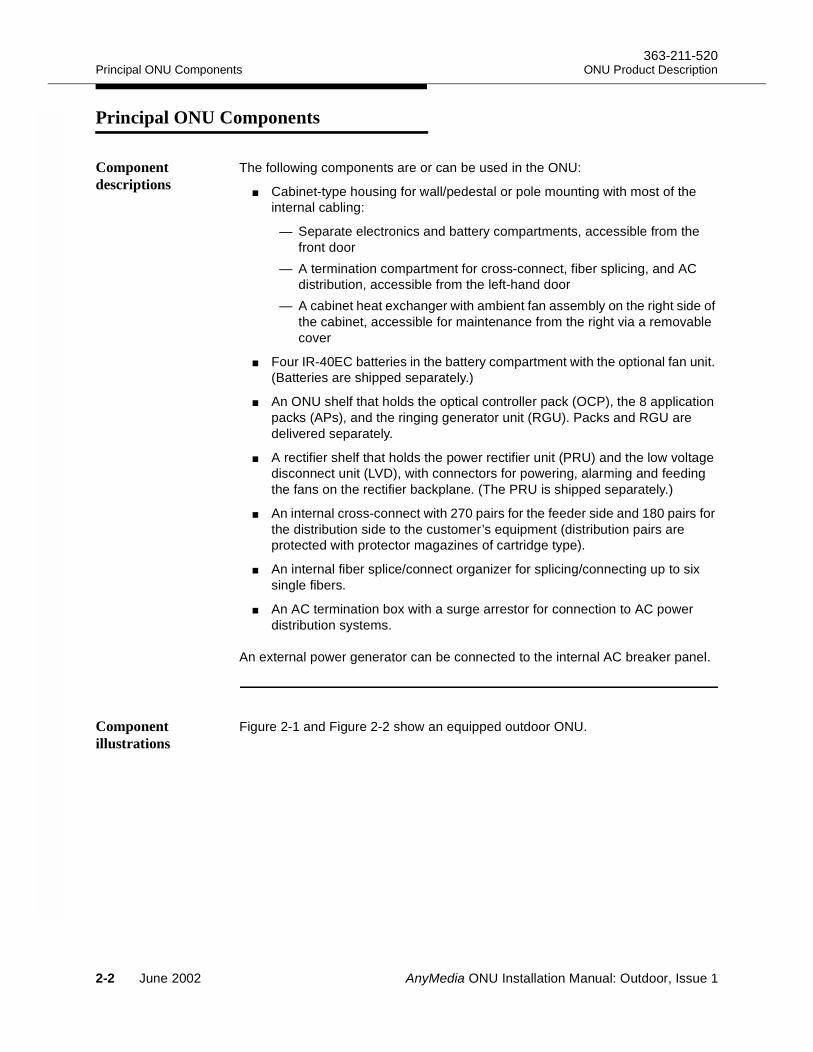
The following components are or can be used in the ONU:
Cabinet-type housing for wall/pedestal or pole mounting with most of the internal cabling:
— Separate electronics and battery compartments, accessible from the front door
— A termination compartment for cross-connect, fiber splicing, and AC distribution, accessible from the left-hand door
— A cabinet heat exchanger with ambient fan assembly on the right side of the cabinet, accessible for maintenance from the right via a removable cover
Four IR-40EC batteries in the battery compartment with the optional fan unit. (Batteries are shipped separately.)
An ONU shelf that holds the optical controller pack (OCP), the 8 application packs (APs), and the ringing generator unit (RGU). Packs and RGU are delivered separately.
A rectifier shelf that holds the power rectifier unit (PRU) and the low voltage disconnect unit (LVD), with connectors for powering, alarming and feeding the fans on the rectifier backplane. (The PRU is shipped separately.)
An internal cross-connect with 270 pairs for the feeder side and 180 pairs for the distribution side to the customer’s equipment (distribution pairs are protected with protector magazines of cartridge type).
An internal fiber splice/connect organizer for splicing/connecting up to six single fibers.
An AC termination box with a surge arrestor for connection to AC power distribution systems.
An external power generator can be connected to the internal AC breaker panel.
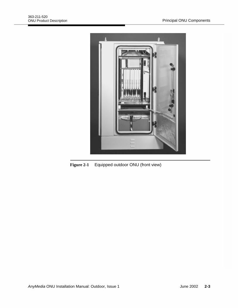
Component illustrations
Figure 2-1 and Figure 2-2 show an equipped outdoor ONU.
2-2 June 2002 AnyMedia ONU Installation Manual: Outdoor, Issue 1
363-211-520Principal ONU ComponentsONU Product Description
Figure 2-1 Equipped outdoor ONU (front view)
AnyMedia ONU Installation Manual: Outdoor, Issue 1 June 2002 2-3
Principal ONU Components363-211-520
ONU Product Description
Figure 2-2 Side views of an equipped outdoor ONU (door open/cover removed)
2-4 June 2002 AnyMedia ONU Installation Manual: Outdoor, Issue 1
AnyMedia ONU Installation Manual: Outdoor, Issue 1
Overview of the Installation Process3Overview 3
This chapter summarizes the ONU installation and cabling process and lists the tools and test instruments you will need to accomplish the installation.
Contents
Page
Installation Sequence 3-2 Tools and Measurement /Testing Instruments 3-4
June 2002 3-1
Installation Sequence363-211-520
Overview of the Installation Process
Installation Sequence 3
This manual covers the outdoor ONU installation process that starts with the preparation of the site ground. It is assumed that the any civil works (foundation construction) and cable runs to the ONU mounting area are complete.
The recommended installation sequence is as follows:
1. For pedestal mounted ONUs, install the site ground and pedestal and fasten the pedestal to the foundation pad.
2. Pull the cables for AC power, subscriber lines, and fibers through this pedestal.
3. Mount the Krone cross-connect inside the ONU termination compartment and cable it.
4. Mount and secure the ONU.
5. Immediately after mounting, ground the ONU to the site ground. Measure the ground resistance and ensure that it is less than the specified tolerance.
6. Route the cables through the termination compartment, ground them and seal them. Verify all cable grounds.
7. Route the fibers to the fiber splice box
8. Set the ONU number, mark the TAP100 test cable (if applicable), and interconnect the test application paths in the internal Krone cross-connect.
9. Connect the subscriber pairs to the distribution side of the Krone cross-connect. For POTS and ATM xDSL applications, make the cross-connections from the distribution side to the feeder side of the cross-connect.
NOTE:For ATM xDSL-only applications, no cross-connections are required.
10. If ADSL APs are used for POTS and ATM xDSL applications, reroute POTS subscriber lines on the feeder side of the cross-connect.
NOTE:For ATM xDSL-only applications, no rerouting is required.
11. Test the cross-connect cabling and equip all termination blocks on the distribution side of the cross-connect with protector blocks for primary protection.
12. Dress and splice the fiber at the ONU (and at the AnyMedia FAST shelf, if required).
3-2 June 2002 AnyMedia ONU Installation Manual: Outdoor, Issue 1
363-211-520Installation SequenceOverview of the Installation Process
13. Connect the AC cable from the utility side in the AC termination box (with the AC circuit breaker switched off).
14. Install the IR-40EC or IR-30EC batteries and connect them to the internal battery cable. Check all batteries and the battery and string voltages before installation.
15. Equip the rectifier shelf with the power rectifier unit (PRU) and with the low voltage disconnect unit (LVD).
16. If the ONU is expected to support POTS applications, install the PRU in the rectifier shelf.
17. Apply AC power and check the rectifier voltage.
18. Switch off the low voltage disconnect unit, connect the battery cable and the thermal probe cable to the PRU and turn on the LVD.
19. Charge the batteries for at least for 48 hours.
20. Equip the ONU shelf with the OCP and with APs, as instructed in AnyMedia Access System Commands and Procedures on-line documentation (363-211-103).
AnyMedia ONU Installation Manual: Outdoor, Issue 1 June 2002 3-3
Tools and Measurement /Testing Instruments363-211-520
Overview of the Installation Process
Tools and Measurement /Testing Instruments 3
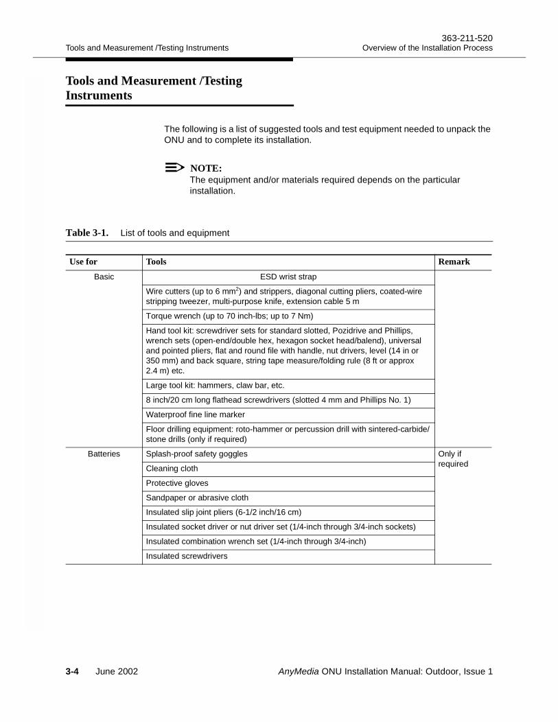
The following is a list of suggested tools and test equipment needed to unpack the ONU and to complete its installation.
NOTE:The equipment and/or materials required depends on the particular installation.
Table 3-1. List of tools and equipment
Use for Tools RemarkBasic ESD wrist strap
Wire cutters (up to 6 mm2) and strippers, diagonal cutting pliers, coated-wire stripping tweezer, multi-purpose knife, extension cable 5 m
Torque wrench (up to 70 inch-lbs; up to 7 Nm)
Hand tool kit: screwdriver sets for standard slotted, Pozidrive and Phillips, wrench sets (open-end/double hex, hexagon socket head/balend), universal and pointed pliers, flat and round file with handle, nut drivers, level (14 in or 350 mm) and back square, string tape measure/folding rule (8 ft or approx 2.4 m) etc.
Large tool kit: hammers, claw bar, etc.
8 inch/20 cm long flathead screwdrivers (slotted 4 mm and Phillips No. 1)
Waterproof fine line marker
Floor drilling equipment: roto-hammer or percussion drill with sintered-carbide/stone drills (only if required)
Batteries Splash-proof safety goggles Only if requiredCleaning cloth
Protective gloves
Sandpaper or abrasive cloth
Insulated slip joint pliers (6-1/2 inch/16 cm)
Insulated socket driver or nut driver set (1/4-inch through 3/4-inch sockets)
Insulated combination wrench set (1/4-inch through 3/4-inch)
Insulated screwdrivers
3-4 June 2002 AnyMedia ONU Installation Manual: Outdoor, Issue 1
363-211-520Tools and Measurement /Testing InstrumentsOverview of the Installation Process
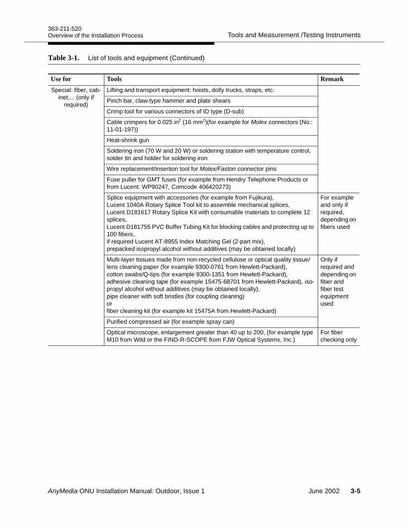
Special: fiber, cab-inet,... (only if
required)
Lifting and transport equipment: hoists, dolly trucks, straps, etc.
Pinch bar, claw-type hammer and plate shears
Crimp tool for various connectors of ID type (D-sub)
Cable crimpers for 0.025 in2 (16 mm2)(for example for Molex connectors (No.: 11-01-197))
Heat-shrink gun
Soldering iron (70 W and 20 W) or soldering station with temperature control, solder tin and holder for soldering iron
Wire replacement/insertion tool for Molex/Faston connector pins
Fuse puller for GMT fuses (for example from Hendry Telephone Products or from Lucent: WP90247, Comcode 406420273)
Splice equipment with accessories (for example from Fujikura),Lucent 1040A Rotary Splice Tool kit to assemble mechanical splices,Lucent D181617 Rotary Splice Kit with consumable materials to complete 12 splices,Lucent D181755 PVC Buffer Tubing Kit for blocking cables and protecting up to 100 fibers,if required Lucent AT-8955 Index Matching Gel (2-part mix),prepacked isopropyl alcohol without additives (may be obtained locally)
For example and only if required, depending on fibers used
Multi-layer tissues made from non-recycled cellulose or optical quality tissue/lens cleaning paper (for example 9300-0761 from Hewlett-Packard), cotton swabs/Q-tips (for example 9300-1351 from Hewlett-Packard), adhesive cleaning tape (for example 15475-68701 from Hewlett-Packard), iso-propyl alcohol without additives (may be obtained locally),pipe cleaner with soft bristles (for coupling cleaning)orfiber cleaning kit (for example kit 15475A from Hewlett-Packard)
Only if required and depending on fiber and fiber test equipment used
Purified compressed air (for example spray can)
Optical microscope, enlargement greater than 40 up to 200, (for example type M10 from Wild or the FIND-R-SCOPE from FJW Optical Systems, Inc.)
For fiber checking only
Table 3-1. List of tools and equipment (Continued)
Use for Tools Remark
AnyMedia ONU Installation Manual: Outdoor, Issue 1 June 2002 3-5
Tools and Measurement /Testing Instruments363-211-520
Overview of the Installation Process
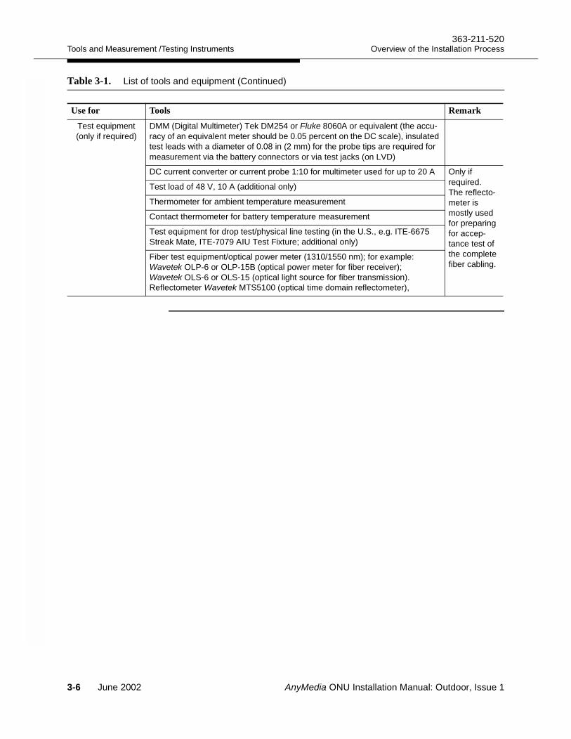
Test equipment (only if required)
DMM (Digital Multimeter) Tek DM254 or Fluke 8060A or equivalent (the accu-racy of an equivalent meter should be 0.05 percent on the DC scale), insulated test leads with a diameter of 0.08 in (2 mm) for the probe tips are required for measurement via the battery connectors or via test jacks (on LVD)
DC current converter or current probe 1:10 for multimeter used for up to 20 A Only if required.The reflecto-meter is mostly used for preparing for accep-tance test of the complete fiber cabling.
Test load of 48 V, 10 A (additional only)
Thermometer for ambient temperature measurement
Contact thermometer for battery temperature measurement
Test equipment for drop test/physical line testing (in the U.S., e.g. ITE-6675 Streak Mate, ITE-7079 AIU Test Fixture; additional only)
Fiber test equipment/optical power meter (1310/1550 nm); for example: Wavetek OLP-6 or OLP-15B (optical power meter for fiber receiver);Wavetek OLS-6 or OLS-15 (optical light source for fiber transmission).Reflectometer Wavetek MTS5100 (optical time domain reflectometer),
Table 3-1. List of tools and equipment (Continued)
Use for Tools Remark
3-6 June 2002 AnyMedia ONU Installation Manual: Outdoor, Issue 1
AnyMedia ONU Installation Manual: Outdoor, Issue 1
Site Ground for Pedestal Mounted ONUs 4Overview 4
This chapter addresses the site grounding requirements and recommended connections for a pedestal-mounted ONU. This chapter does not apply to pole-mounted or wall-mounted ONUs.
Contents
Page
Site Ground Requirements 4-2 Recommended Connections 4-3
June 2002 4-1
Site Ground Requirements363-211-520
Site Ground for Pedestal Mounted ONUs
Site Ground Requirements 4
In order for the ONU to operate reliably and safely, it must be connected to an appropriate site ground. The design of the site ground should conform to local practice and be based on the following principles:
The ONU should never be operated with a disconnected ground.
The installation must have an independent ground connection to an approved ground electrode for outdoor applications. The minimum size of the independent ground connection should be ≥ 0.025 in2 (16 mm)2 or ≤ 6 AWG. Adhere to the ITU recommendation ITU-K.35.
A minimum of two ground rods driven into the ground are required, one at each end of the ONU housing. When driven, the rods should be flush with or slightly below ground level to enable inspection of the attached conductor.
Grounding wires connected to the approved ground terminal should be available before you begin the installation of the ONU.
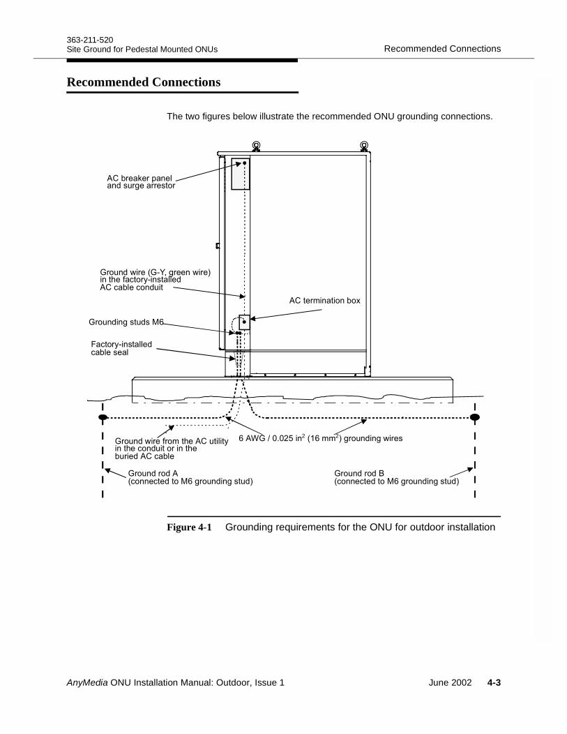
The ground wire from the left side of the ONU (termination side) should be terminated at one of the grounding studs. This wire should be run as directly as possible and terminated, unspliced, to the ground rod (see Figure 4-1). The lug should be crimped; soldering is not allowed. The use of a double-hole lug is mandatory.
The ground wire from the right side of the ONU should also be terminated at one of the grounding studs.
The ground wire from the AC termination box of the ONU housing should be connected to one of the cabinet grounding studs located at the bottom of the side compartment.
All cable sheaths of the external outdoor cables must be correctly connected to the cabinet grounding studs immediately after the housing is installed.
When installing ground wires in a conduit, you must use non-metallic conduit.
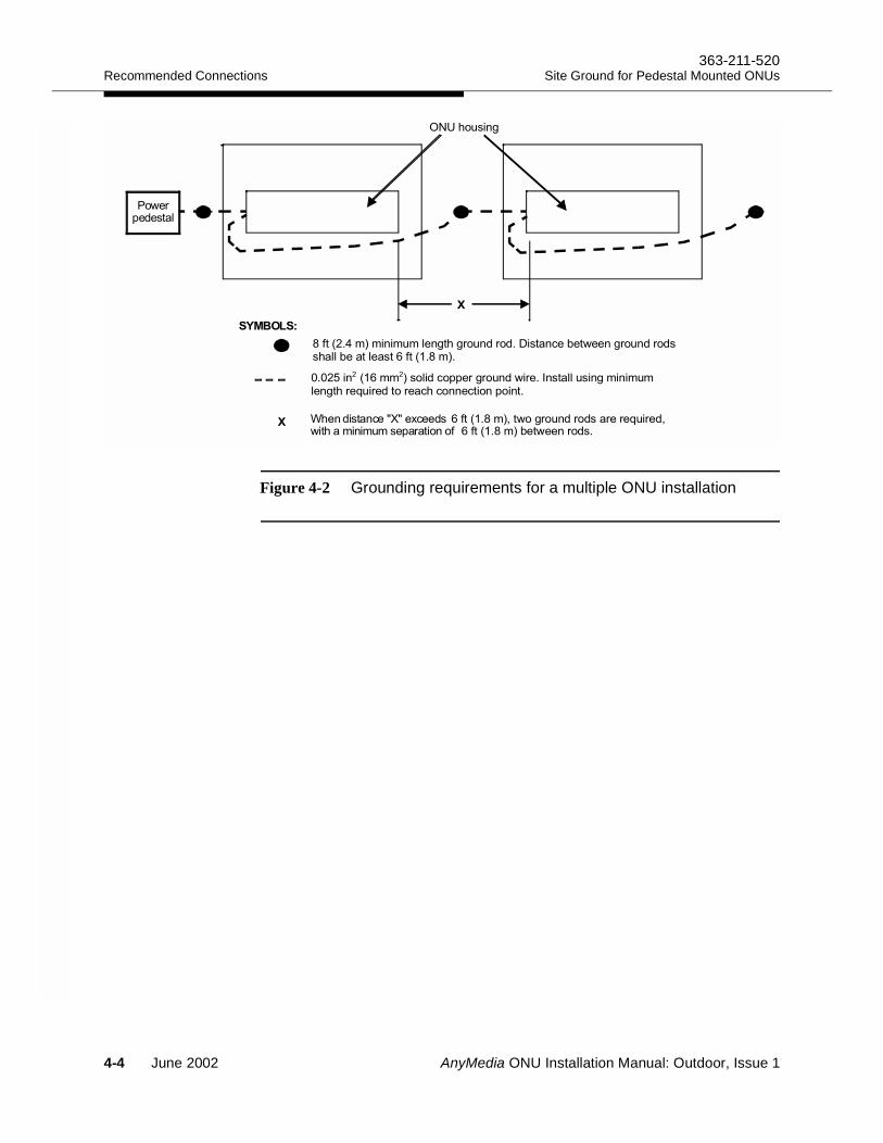
For installations involving multiple cabinets, the cabinets should be interconnected by 16 mm2 solid copper ground wires of minimum length. Where cabinets or pedestals are separated by less than 6 ft (1.8 m), they can share a common centrally located ground rod. See Figure 4-2 for a typical grounding arrangement.
4-2 June 2002 AnyMedia ONU Installation Manual: Outdoor, Issue 1
363-211-520Recommended ConnectionsSite Ground for Pedestal Mounted ONUs
Recommended Connections 4
The two figures below illustrate the recommended ONU grounding connections.
Figure 4-1 Grounding requirements for the ONU for outdoor installation
'$#%-'"',)" $!*#)"(#%$'#)" $'"% ( !"
'"."'&#"!#%$'/"''"'
'$#%-'"0+1/'""#-'"2#)"('*+#!!"% ( !"(#%$
'$#%#/$%3
('*+#!!"%( !""!
'$#%'% 0(##"("%3/'$#%#/$%2
3 45667#03,,2/'$#%#/-'"
'$#%'%80(##"("%3/'$#%#/$%2
"',## 9
AnyMedia ONU Installation Manual: Outdoor, Issue 1 June 2002 4-3
Recommended Connections363-211-520
Site Ground for Pedestal Mounted ONUs
Figure 4-2 Grounding requirements for a multiple ONU installation
!"#$%
" !&#'%'" !&#(
& )#*((" !&#
4-4 June 2002 AnyMedia ONU Installation Manual: Outdoor, Issue 1
AnyMedia ONU Installation Manual: Outdoor, Issue 1
Mounting the ONU 5Overview 5
This chapter describes the procedures for mounting the cross-connects in the ONU termination compartment; for mounting/installing the ONU; and for connecting it to the site ground. These mounting procedures must be performed before you connect any external cables to the ONU or power-up the system.
ontents
Page
Mounting and Installing the Optional Cross-Connect 5-3Cross-connect alternatives 5-3Connecting T/R-cables for the base housing configuration 5-9Installing the TAP-B cable (option) 5-11TAP-B cable installation procedure 5-13
Pedestal Mount 5-17Foundation pad cabling arrangement 5-17Positioning the pedestal 5-18Positioning and securing the ONU 5-18
Wall Mount 5-20Preparing for wall-mounting 5-20Installing the wall-mounting plate on the wall 5-20Installing the ONU on the wall-mount plate 5-21
June 2002 5-1
Overview363-211-520
Mounting the ONU
Pole Mount 5-24Preparation for pole-mounting 5-24Securing the pole-mount bracket to the pole 5-25Installing the ONU on the pole 5-27
Page
5-2 June 2002 AnyMedia ONU Installation Manual: Outdoor, Issue 1
363-211-520 Mounting and Installing the Optional Cross-ConnectMounting the ONU
Mounting and Installing the Optional Cross-Connect 5
This section provides requirements and procedures for mounting and installing a Krone cross-connect (two types are available) in the ED7C851-50 Grx ONU base housing.
NOTE:When mounting the ONU on a wall or pole it is advisable to pre-install the Krone cross-connect and all optional delivered parts while the ONU housing is still on the ground to simplify installation.
Cross-connect alternatives
The Krone cross-connect is available in either of two configurations:
For xDSL-only applications:
— Krone cross-connect kit ED7C851-56 Gr.3 with a combined feeder/distribution side having 27 disconnection modules (type 2/10; top/bottom access)
For combined POTS and xDSL applications:
— Feeder side. Krone cross-connect kit ED7C851-56 Gr.1 with 27 high density connection modules (type 10/10; front/rear access)
— Distribution side. Krone cross-connect kit ED7C851-56 Gr.2 with disconnection modules (type 2/10; top/bottom access)
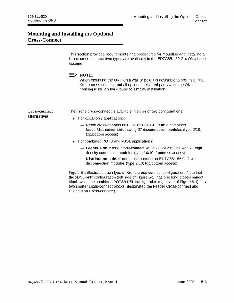
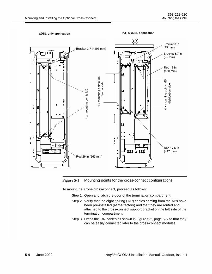
Figure 5-1 illustrates each type of Krone cross-connect configuration. Note that the xDSL-only configuration (left side of Figure 5-1) has one long cross-connect block, while the combined POTS/xDSL configuration (right side of Figure 5-1) has two shorter cross-connect blocks (designated the Feeder Cross-connect and Distribution Cross-connect).
AnyMedia ONU Installation Manual: Outdoor, Issue 1 June 2002 5-3
Mounting and Installing the Optional Cross-Connect363-211-520
Mounting the ONU
Figure 5-1 Mounting points for the cross-connect configurations
To mount the Krone cross-connect, proceed as follows:
Step 1. Open and latch the door of the termination compartment.Step 2. Verify that the eight tip/ring (T/R) cables coming from the APs have
been pre-installed (at the factory) and that they are routed and attached to the cross-connect support bracket on the left side of the termination compartment.
Step 3. Dress the T/R-cables as shown in Figure 5-2, page 5-5 so that they can be easily connected later to the cross-connect modules.
9,
$##/&#
7
9,
$##/&#
7""%"'%"
9,
$##/&#
7
%' $#%"
8'(.":#
8'(."#
%;#
%:3#
8'(.":#0<7,,2
%3#033,,2
0:,,2
036,,2
0<7,,2
0:7,,2
5-4 June 2002 AnyMedia ONU Installation Manual: Outdoor, Issue 1
363-211-520 Mounting and Installing the Optional Cross-ConnectMounting the ONU
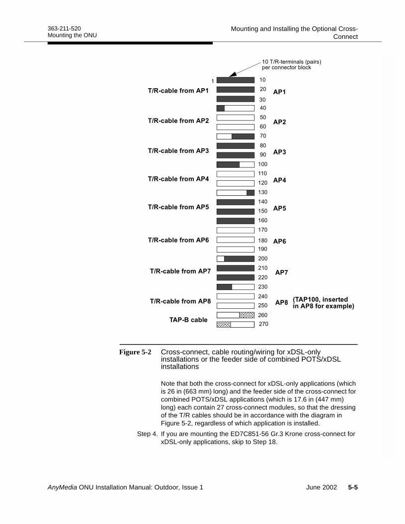
Figure 5-2 Cross-connect, cable routing/wiring for xDSL-only installations or the feeder side of combined POTS/xDSL installations
Note that both the cross-connect for xDSL-only applications (which is 26 in (663 mm) long) and the feeder side of the cross-connect for combined POTS/xDSL applications (which is 17.6 in (447 mm) long) each contain 27 cross-connect modules, so that the dressing of the T/R cables should be in accordance with the diagram in Figure 5-2, regardless of which application is installed.
Step 4. If you are mounting the ED7C851-56 Gr.3 Krone cross-connect for xDSL-only applications, skip to Step 18.
6
6
6
;6
6
76
36
:6
;6
<6
66
6
6
6
6
76
36
:6
!
65+"',#!0&'2&"'(##"(' !(.
6
66
6
6
6
!
AnyMedia ONU Installation Manual: Outdoor, Issue 1 June 2002 5-5
Mounting and Installing the Optional Cross-Connect363-211-520
Mounting the ONU
Step 5. For combined POTS/xDSL applications locate the ED7C851-56 Gr.1/Gr.2 Krone cross-connect kit with the brackets and rods as follows:
a. For the feeder side: two 3 in (75 mm) rod brackets and two 17.6 in (447 mm) rods
b. For the distribution side: two 3.7 in (95 mm) rod brackets and two 18 in (460 mm) rods
Step 6. Refer to the equipment configuration illustrated on the right-hand side of Figure 5-1, page 5-4. Using four M5 screws, install the rods and brackets on the cross-connect support bracket located on the left-hand side of the termination compartment.
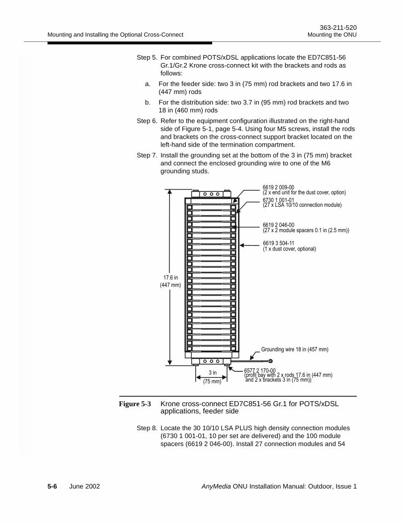
Step 7. Install the grounding set at the bottom of the 3 in (75 mm) bracket and connect the enclosed grounding wire to one of the M6 grounding studs.
Figure 5-3 Krone cross-connect ED7C851-56 Gr.1 for POTS/xDSL applications, feeder side
Step 8. Locate the 30 10/10 LSA PLUS high density connection modules (6730 1 001-01, 10 per set are delivered) and the 100 module spacers (6619 2 046-00). Install 27 connection modules and 54
!
" #$ %
! "&'(# & )!
! $ %
* +( ,!
!
5-6 June 2002 AnyMedia ONU Installation Manual: Outdoor, Issue 1
363-211-520 Mounting and Installing the Optional Cross-ConnectMounting the ONU
spacers on the feeder side (the side with the 3 in (75 mm) wide bracket), as shown in Figure 5-3, page 5-6. Mount each module with Terminal 1 on the left and the white-colored side of the module faces front.
Step 9. If you have an optional dust cover (6619 3 504-11), install the two end units (6619 2 009-00) and attach the cover.
Step 10.Using four M5 screws, install the 3.7 in (95 mm) brackets and the two 18 in (460 mm) rods on the right side of the back panel, as shown in Figure 5-1, page 5-4, right-hand illustration.
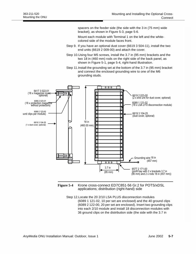
Step 11.Install the grounding set at the bottom of the 3.7 in (95 mm) bracket and connect the enclosed grounding wire to one of the M6 grounding studs.
Figure 5-4 Krone cross-connect ED7C851-56 Gr.2 for POTS/xDSL applications; distribution (right-hand) side
Step 12.Locate the 20 2/10 LSA PLUS disconnection modules (6089 1 121-02, 10 per set are enclosed) and the 40 ground clips (6089 2 122-00, 20 per set are enclosed). Insert two grounding clips into each 2/10 module and install 18 disconnection modules with 36 ground clips on the distribution side (the side with the 3.7 in
!
! "&'(# & )! ,!
" $ %
,,
!$ %
, +-$ %
, +-
* +( !
(#
,
,
AnyMedia ONU Installation Manual: Outdoor, Issue 1 June 2002 5-7
Mounting and Installing the Optional Cross-Connect363-211-520
Mounting the ONU
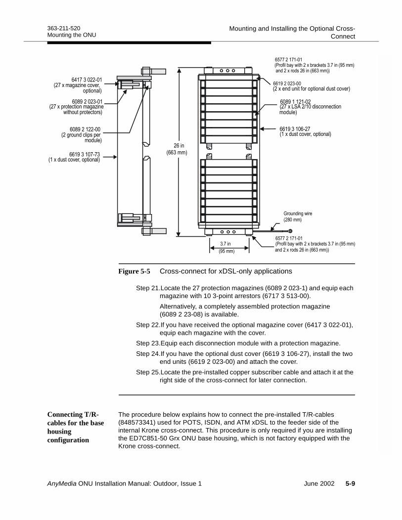
(95 mm) bracket)) as shown in Figure 5-4, page 5-7. (Two of the disconnection modules are spares.)
Step 13.Locate the 18 protection magazines (6089 2 023-1) and equip each magazine with 10 3-point arrestors (6717 3 513-00). Alternatively, a completely assembled protection magazine (6089 2 23-08) is available.
Step 14.If you have received the optional magazine cover (6417 3 022-01), equip each magazine with the cover.
Step 15.Equip each disconnection module with a protection magazine.Step 16.If you have received the optional dust cover (6619 3 104-25), install
the two end units (6619 2 023-00) and attach the cover.Step 17.This completes the installation of the cross-connects for
POTS/xDSL applications. Proceed to Step 25.Step 18.For xDSL-only applications, locate the ED7C851-56 Gr.3 Krone
cross-connect kit with the brackets and rods to be mounted on the left side. The kit contains:
a. two 3.7 in (95 mm) rod brackets b. two 26 in (663 mm) rods
Step 19.Using four M5 screws, install the two 3.7 in (95 mm) brackets and the two 26 in (663 mm) rods on the cross-connect support bracket located on the left side of the termination compartment, as shown in Figure 5-1, page 5-4.
Step 20.Locate the 30 2/10 LSA PLUS disconnection modules (6089 1 121-02, 10 per set are enclosed) and the 60 ground clips (6089 2 122-00, 20 per set are enclosed). Insert two grounding clips into each 2/10 module and install 27 disconnection modules with the 56 ground clips on the distribution side (the side with the 3.7 in (95 mm) bracket) as shown in Figure 5-5, page 5-9. (Three of the disconnection modules are spares.)
5-8 June 2002 AnyMedia ONU Installation Manual: Outdoor, Issue 1
363-211-520 Mounting and Installing the Optional Cross-ConnectMounting the ONU
Figure 5-5 Cross-connect for xDSL-only applications
Step 21.Locate the 27 protection magazines (6089 2 023-1) and equip each magazine with 10 3-point arrestors (6717 3 513-00). Alternatively, a completely assembled protection magazine (6089 2 23-08) is available.
Step 22.If you have received the optional magazine cover (6417 3 022-01), equip each magazine with the cover.
Step 23.Equip each disconnection module with a protection magazine.Step 24.If you have the optional dust cover (6619 3 106-27), install the two
end units (6619 2 023-00) and attach the cover.Step 25.Locate the pre-installed copper subscriber cable and attach it at the
right side of the cross-connect for later connection.
Connecting T/R-cables for the base housing configuration
The procedure below explains how to connect the pre-installed T/R-cables (848573341) used for POTS, ISDN, and ATM xDSL to the feeder side of the internal Krone cross-connect. This procedure is only required if you are installing the ED7C851-50 Grx ONU base housing, which is not factory equipped with the Krone cross-connect.
!!
!"#$
"# ! $
%&
!!
" $
%
AnyMedia ONU Installation Manual: Outdoor, Issue 1 June 2002 5-9
Mounting and Installing the Optional Cross-Connect363-211-520
Mounting the ONU
The T/R-cables are approximately 10 ft (≈ 3 m) long. At one end, they are connected to the blank faceplates (C 847773389) on the ONU shelf; at the other end, they are attached to the cross-connect support bracket on the left side of the termination compartment.
Preparation 5
If not factory prepared, all T/R-cable connectors should be manually marked by the installer in accordance with the route/system numbering scheme. The MDF circuit labeling should follow this numbering pattern.
Assignment 5
Figure 5-2 on page 5-5 provides an example of the cross-connect assignments for a Krone cross-connect with 10 T/R-terminals per connector block. Note that this connector block is also used to connect the TAP-B cable (see “Installing the TAP-B cable (option)” on page 5-11). In this illustration, seven pairs of terminals 257 to 270 (shown cross-hatched) on the feeder side of the internal cross-connect are used.
Procedures for installing and attaching the T/R-cables 5
Install the T/R-cables as follows.
Step 1. Dress the T/R-cables as indicated in Figure 5-2 so that they can easily connected to cross-connect modules.
Step 2. Locate the T/R-cable (should be labeled AP1) attached to the blank faceplate of the AP-1 slot.
Step 3. Remove the cable sheath to allow pairs 1 to 10 to dress above module 1, pairs 11 to 20 above module 2, pairs 21 to 30 above module 3 and pairs 31 and 32 above module 4.
Step 4. Using the Krone insertion tool (6417 2 055-01), press the first 10 pairs into the connecting slots of module 1 and trim any access wire. It is recommended that the modules are wired with the a-wire (Tip) terminated on the left position of each connecting pair of the module when viewed from the front.
References: See the AnyMedia Access System Installation Manual, 363-211-102, for connector wiring diagrams.
NOTE:If you connect to the LSA PLUS 10/10 high density modules, the backward cabling from the APs connects to the white side of this module.
If you connect to the LSA 2/10 modules (for xDSL-only cross-connect), the T/R cable from the APs connects to the top (black-marked) connection row of the module.
5-10 June 2002 AnyMedia ONU Installation Manual: Outdoor, Issue 1
363-211-520 Mounting and Installing the Optional Cross-ConnectMounting the ONU
NOTE:After installation there should be only enough slack wire to enable the cross-connect module to pivot enough to provide access to the rear of the modules. If required, remove modules below the module you are working on to avoid interference.
Step 5. Continue connecting pairs 11 through 20, pairs 21 through 30 and pairs 31 and 32 to modules 2, 3 and 4.
Step 6. Repeat steps 3 through 5 for the other seven T/R cables from the APs, using the appropriate modules.
Step 7. Test the T/R-cabling according to local regulations and practices.
Requirement: There should be no open or shorted wires or tip/ring reversals.
Step 8. For the feeder side of the ED7C851-56 Gr.1 cross-connect (for POTS/xDSL) pivot each LSA PLUS 10/10 high density connection module so that the gray unconnected side shows to the front and the connection slots for pair 1 (marked by a “1”) are on the left side.
Installing the TAP-B cable (option)
This procedure consists of connecting the prefabricated TAP-B cable to the cross-connect.
Cable Description 5
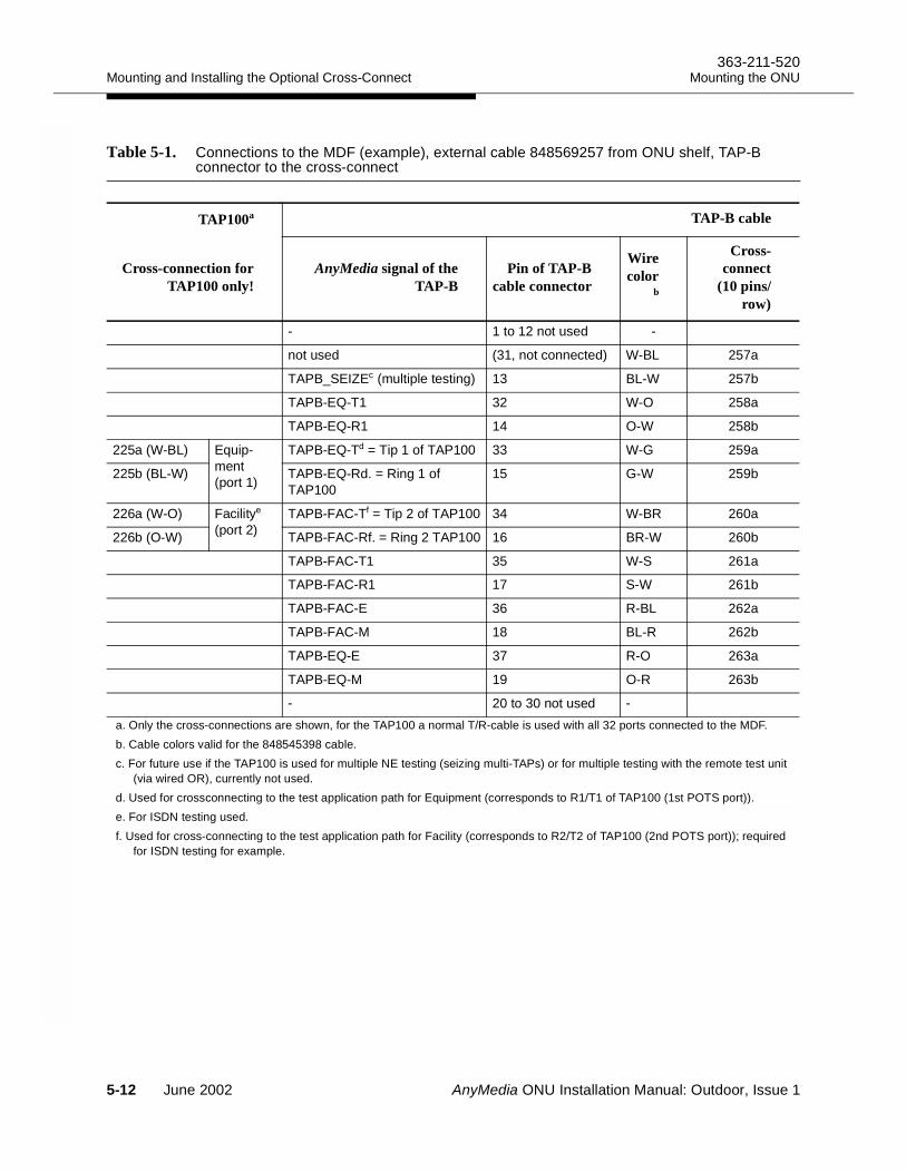
The TAP-B cable (848569257) is used in for drop testing. It has 12 wires and is 10 ft (≈ 3 m) long. One end is attached to the cross-connect support bracket on the left side of the termination compartment. The other end is connected to the 37-pin D-sub connector C1 (marked TAP) on the ONU shelf. Not all pins on this 37-pin connector are connected; only 4 wires are required for integrated drop testing and monitoring. These wires must be connected at the cross-connect to the 4 wires (circuits 1 and 2) of the TAP100 cable. The fifth wire is reserved for future use (seizing).
If not factory prepared, the TAP-B cable should be marked manually by the installer in accordance with the route/system numbering scheme.
The wiring of the TAP connector for the TAP-B cable is shown in Table 5-1. This table illustrates the MDF connections for the TAP-B cable, as an example.
AnyMedia ONU Installation Manual: Outdoor, Issue 1 June 2002 5-11
Mounting and Installing the Optional Cross-Connect363-211-520
Mounting the ONU
Table 5-1. Connections to the MDF (example), external cable 848569257 from ONU shelf, TAP-B connector to the cross-connect
TAP100a TAP-B cable
Cross-connection forTAP100 only!
AnyMedia signal of theTAP-B
Pin of TAP-Bcable connector
Wirecolor
b
Cross-connect
(10 pins/row)
- 1 to 12 not used -
not used (31, not connected) W-BL 257a
TAPB_SEIZEc (multiple testing) 13 BL-W 257b
TAPB-EQ-T1 32 W-O 258a
TAPB-EQ-R1 14 O-W 258b
225a (W-BL) Equip-ment(port 1)
TAPB-EQ-Td = Tip 1 of TAP100 33 W-G 259a
225b (BL-W) TAPB-EQ-Rd. = Ring 1 of TAP100
15 G-W 259b
226a (W-O) Facilitye
(port 2)TAPB-FAC-Tf = Tip 2 of TAP100 34 W-BR 260a
226b (O-W) TAPB-FAC-Rf. = Ring 2 TAP100 16 BR-W 260b
TAPB-FAC-T1 35 W-S 261a
TAPB-FAC-R1 17 S-W 261b
TAPB-FAC-E 36 R-BL 262a
TAPB-FAC-M 18 BL-R 262b
TAPB-EQ-E 37 R-O 263a
TAPB-EQ-M 19 O-R 263b
+ 20 to 30 not used +
a. Only the cross-connections are shown, for the TAP100 a normal T/R-cable is used with all 32 ports connected to the MDF.b. Cable colors valid for the 848545398 cable.c. For future use if the TAP100 is used for multiple NE testing (seizing multi-TAPs) or for multiple testing with the remote test unit
(via wired OR), currently not used.d. Used for crossconnecting to the test application path for Equipment (corresponds to R1/T1 of TAP100 (1st POTS port)).e. For ISDN testing used.f. Used for cross-connecting to the test application path for Facility (corresponds to R2/T2 of TAP100 (2nd POTS port)); required
for ISDN testing for example.
5-12 June 2002 AnyMedia ONU Installation Manual: Outdoor, Issue 1
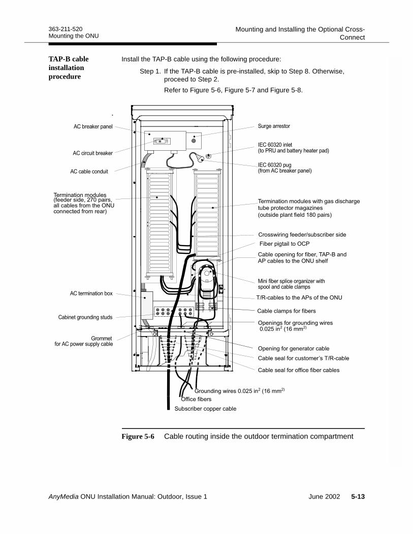
363-211-520 Mounting and Installing the Optional Cross-ConnectMounting the ONU
TAP-B cable installation procedure
Install the TAP-B cable using the following procedure:
Step 1. If the TAP-B cable is pre-installed, skip to Step 8. Otherwise, proceed to Step 2.Refer to Figure 5-6, Figure 5-7 and Figure 5-8.
Figure 5-6 Cable routing inside the outdoor termination compartment
!" #"$
!%"%
!
"#$%&%!
" %&' ( &')*+
%
'
%%
)"
"
)"
)*+ $
( &
, - !
)
.""
&')*+
/")'
%
- !
"0
AnyMedia ONU Installation Manual: Outdoor, Issue 1 June 2002 5-13
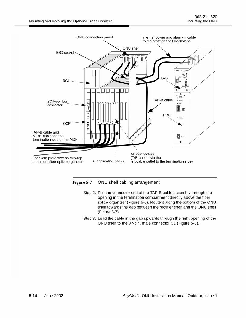
Mounting and Installing the Optional Cross-Connect363-211-520
Mounting the ONU
Figure 5-7 ONU shelf cabling arrangement
Step 2. Pull the connector end of the TAP-B cable assembly through the opening in the termination compartment directly above the fiber splice organizer (Figure 5-6). Route it along the bottom of the ONU shelf towards the gap between the rectifier shelf and the ONU shelf (Figure 5-7).
Step 3. Lead the cable in the gap upwards through the right opening of the ONU shelf to the 37-pin, male connector C1 (Figure 5-82
(##"(#&#"! #"'#!&-"'#%!',+#( !"
;&&!(#&(.
(##"('05+( !"=)"!"( !"$!")""',##%"2
)"'"("')"! (.&!#"
)'
./0
0123.4*
4.56
,+
. 1"
2.34)"!
, 7 863 ./ .92*, 7 , 7
563
'+
5-14 June 2002 AnyMedia ONU Installation Manual: Outdoor, Issue 1
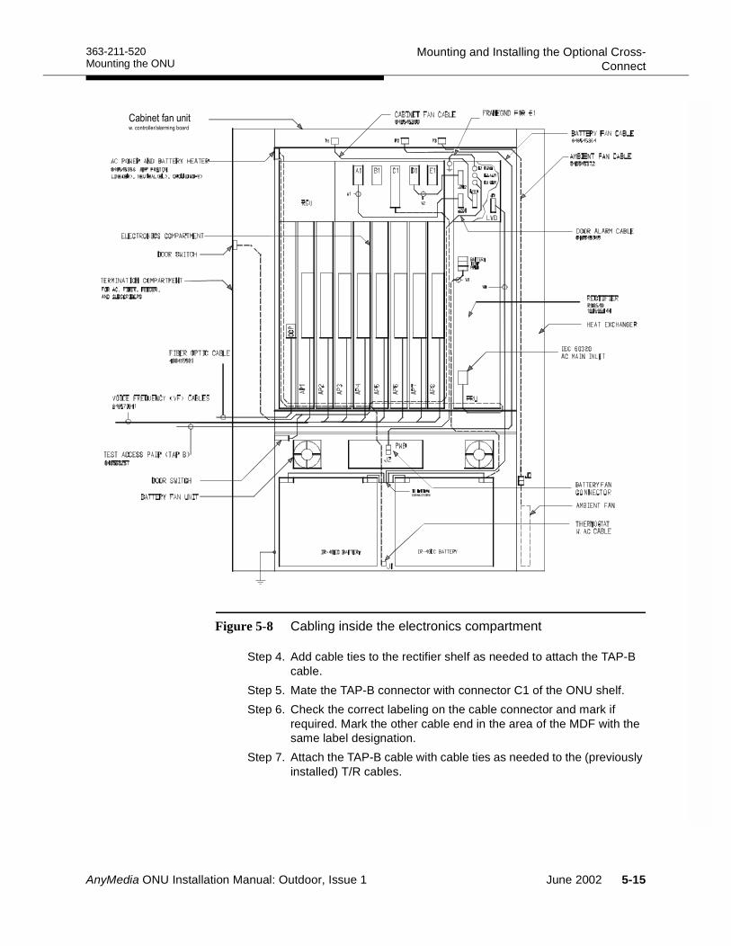
363-211-520 Mounting and Installing the Optional Cross-ConnectMounting the ONU
Figure 5-8 Cabling inside the electronics compartment
Step 4. Add cable ties to the rectifier shelf as needed to attach the TAP-B cable.
Step 5. Mate the TAP-B connector with connector C1 of the ONU shelf.Step 6. Check the correct labeling on the cable connector and mark if
required. Mark the other cable end in the area of the MDF with the same label designation.
Step 7. Attach the TAP-B cable with cable ties as needed to the (previously installed) T/R cables.
0&"( +&
AnyMedia ONU Installation Manual: Outdoor, Issue 1 June 2002 5-15
Mounting and Installing the Optional Cross-Connect363-211-520
Mounting the ONU
Step 8. Dress the TAP-B cable so that it can be connected to the lowest module of the feeder side of the cross-connect. Remove the cable sheath for about 8 in (20 cm).
Step 9. Connect the TAP-B cable to the cross-connect according to Figure 5-2, page 5-5 and Table 5-1., page 5-12.
NOTE:The TAP-B cable is a 13-wire cable of which only 5 wires are used. Four of them are for the circuit pair and the drop pair of the metallic test path. The fifth is for future use. For the cabling/interconnections of the metallic test path, see Interconnecting the test application paths (option),page 7-16.
Step 10.Terminate the tip/ring pairs at the cross-connect and check the labeling. Note the wire color-coding sequence of the factory-prepared cable assemblies to facilitate the terminations.
Step 11.Test the TAP-B wiring according to local regulations and practices. There should be no open or shorted wires or tip/ring reversals.
5-16 June 2002 AnyMedia ONU Installation Manual: Outdoor, Issue 1
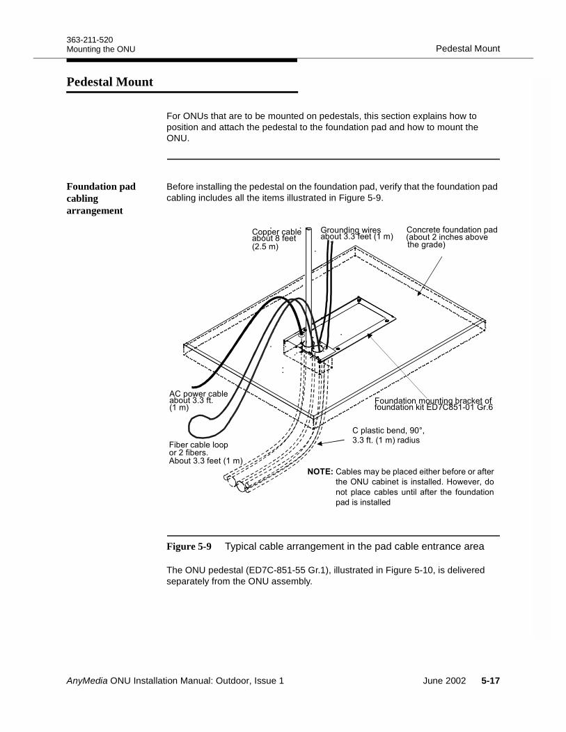
363-211-520Pedestal MountMounting the ONU
Pedestal Mount 5
For ONUs that are to be mounted on pedestals, this section explains how to position and attach the pedestal to the foundation pad and how to mount the ONU.
Foundation pad cabling arrangement
Before installing the pedestal on the foundation pad, verify that the foundation pad cabling includes all the items illustrated in Figure 5-9.
Figure 5-9 Typical cable arrangement in the pad cable entrance area
The ONU pedestal (ED7C-851-55 Gr.1), illustrated in Figure 5-10, is delivered separately from the ONU assembly.
&-"'( !" $
'$#%#/-'" $""0,2
&&"'( !" $;""
$#%#,$##/ '(."$#%#.:;7+6'3
#('""$#%#&%0 $#()" =")"/'%"207,2
&!( "#%1<6>10,2'%$
!",* "&!("%")"' "'"'"'
)"( #" #!!"%-"="'1%
# &!(" ( !"$#! "' )" $#%#
&%#!!"%
"#$
"'( !"!&' "' $""0,2
0,2
AnyMedia ONU Installation Manual: Outdoor, Issue 1 June 2002 5-17
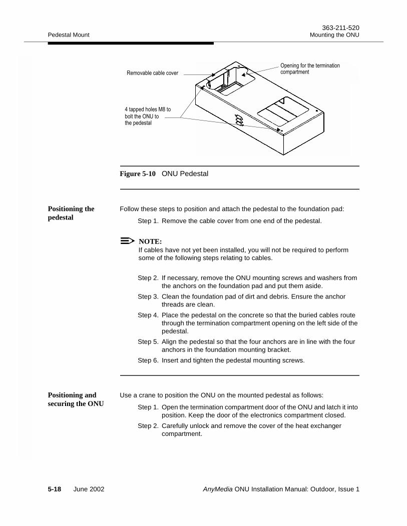
Pedestal Mount363-211-520
Mounting the ONU
Figure 5-10 ONU Pedestal
Positioning the pedestal
Follow these steps to position and attach the pedestal to the foundation pad:
Step 1. Remove the cable cover from one end of the pedestal.
NOTE:If cables have not yet been installed, you will not be required to perform some of the following steps relating to cables.
Step 2. If necessary, remove the ONU mounting screws and washers from the anchors on the foundation pad and put them aside.
Step 3. Clean the foundation pad of dirt and debris. Ensure the anchor threads are clean.
Step 4. Place the pedestal on the concrete so that the buried cables route through the termination compartment opening on the left side of the pedestal.
Step 5. Align the pedestal so that the four anchors are in line with the four anchors in the foundation mounting bracket.
Step 6. Insert and tighten the pedestal mounting screws.
Positioning and securing the ONU
Use a crane to position the ONU on the mounted pedestal as follows:
Step 1. Open the termination compartment door of the ONU and latch it into position. Keep the door of the electronics compartment closed.
Step 2. Carefully unlock and remove the cover of the heat exchanger compartment.
5+" #
#/,
4:#
.$&&$
5-18 June 2002 AnyMedia ONU Installation Manual: Outdoor, Issue 1
363-211-520Pedestal MountMounting the ONU
WARNING:
Step 3. Refer to Figure 6-2, page 6-5. Using appropriate tools, remove two bolts in the termination compartment and two bolts in the heat exchanger compartment that are securing the ONU to the pallet.
Step 4. Remove the cable entrance cover of the ONU cabinet to enable the ONU housing to slide over the cables.
Step 5. Raise the ONU housing approximately 11¾ in (300 mm), guide it over to the mounted pedestal, and slide it over the cables allowing the cables to be dressed through the cable entrance.
Step 6. Slowly lower the ONU housing and align its mounting holes over the upper mounting holes in the pedestal.
NOTE:The ONU housing weighs about 156 lbs (71 kg) and can also be moved into position by at least two people.
Step 7. Secure the ONU using the four M8 bolts and washers supplied with the pedestal. Use the same mounting holes that were used to secure the ONU to the pallet.
Step 8. Verify that all doors open and close freely.Step 9. Remove the B connecting link or clevis from each lifting eye of the
ONU. Move slings and boom line away from the ONU.Step 10.Replace the two cable covers and proceed to Chapter 6 to continue
the ONU installation.
AnyMedia ONU Installation Manual: Outdoor, Issue 1 June 2002 5-19
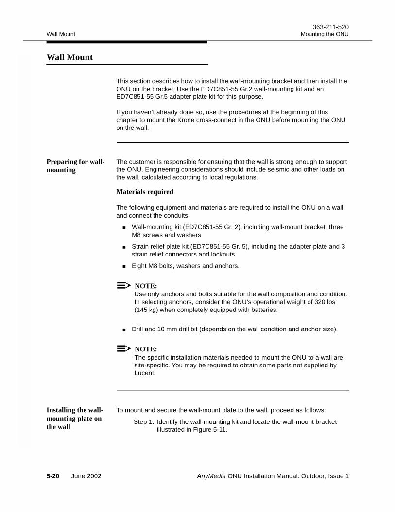
Wall Mount363-211-520
Mounting the ONU
Wall Mount 5
This section describes how to install the wall-mounting bracket and then install the ONU on the bracket. Use the ED7C851-55 Gr.2 wall-mounting kit and an ED7C851-55 Gr.5 adapter plate kit for this purpose.
If you haven’t already done so, use the procedures at the beginning of this chapter to mount the Krone cross-connect in the ONU before mounting the ONU on the wall.
Preparing for wall-mounting
The customer is responsible for ensuring that the wall is strong enough to support the ONU. Engineering considerations should include seismic and other loads on the wall, calculated according to local regulations.
Materials required 5
The following equipment and materials are required to install the ONU on a wall and connect the conduits:
Wall-mounting kit (ED7C851-55 Gr. 2), including wall-mount bracket, three M8 screws and washers
Strain relief plate kit (ED7C851-55 Gr. 5), including the adapter plate and 3 strain relief connectors and locknuts
Eight M8 bolts, washers and anchors.
NOTE:Use only anchors and bolts suitable for the wall composition and condition. In selecting anchors, consider the ONU’s operational weight of 320 lbs (145 kg) when completely equipped with batteries.
Drill and 10 mm drill bit (depends on the wall condition and anchor size).
NOTE:The specific installation materials needed to mount the ONU to a wall are site-specific. You may be required to obtain some parts not supplied by Lucent.
Installing the wall-mounting plate on the wall
To mount and secure the wall-mount plate to the wall, proceed as follows:
Step 1. Identify the wall-mounting kit and locate the wall-mount bracket illustrated in Figure 5-11.
5-20 June 2002 AnyMedia ONU Installation Manual: Outdoor, Issue 1
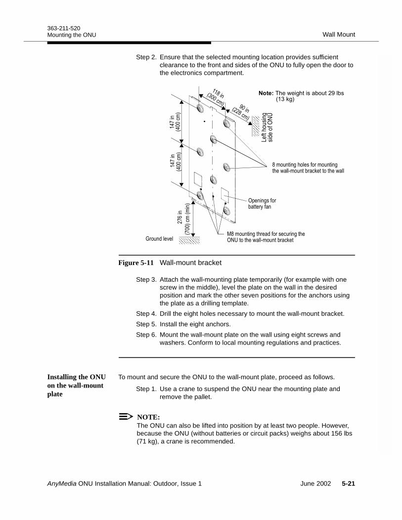
363-211-520Wall MountMounting the ONU
Step 2. Ensure that the selected mounting location provides sufficient clearance to the front and sides of the ONU to fully open the door to the electronics compartment.
Figure 5-11 Wall-mount bracket
Step 3. Attach the wall-mounting plate temporarily (for example with one screw in the middle), level the plate on the wall in the desired position and mark the other seven positions for the anchors using the plate as a drilling template.
Step 4. Drill the eight holes necessary to mount the wall-mount bracket.Step 5. Install the eight anchors. Step 6. Mount the wall-mount plate on the wall using eight screws and
washers. Conform to local mounting regulations and practices.
Installing the ONU on the wall-mount plate
To mount and secure the ONU to the wall-mount plate, proceed as follows.
Step 1. Use a crane to suspend the ONU near the mounting plate and remove the pallet.
NOTE:The ONU can also be lifted into position by at least two people. However, because the ONU (without batteries or circuit packs) weighs about 156 lbs (71 kg), a crane is recommended.
,+#" +#(& )#(
/,+# " +#52:#(& )
5+" & '"
,
* $
"
#
+
"5
2:
"$)"-"/) $<! 0./2
,
AnyMedia ONU Installation Manual: Outdoor, Issue 1 June 2002 5-21
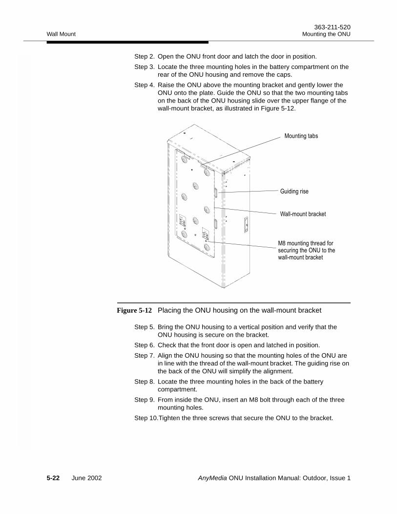
Wall Mount363-211-520
Mounting the ONU
Step 2. Open the ONU front door and latch the door in position.Step 3. Locate the three mounting holes in the battery compartment on the
rear of the ONU housing and remove the caps. Step 4. Raise the ONU above the mounting bracket and gently lower the
ONU onto the plate. Guide the ONU so that the two mounting tabs on the back of the ONU housing slide over the upper flange of the wall-mount bracket, as illustrated in Figure 5-12.
Figure 5-12 Placing the ONU housing on the wall-mount bracket
Step 5. Bring the ONU housing to a vertical position and verify that the ONU housing is secure on the bracket.
Step 6. Check that the front door is open and latched in position.Step 7. Align the ONU housing so that the mounting holes of the ONU are
in line with the thread of the wall-mount bracket. The guiding rise on the back of the ONU will simplify the alignment.
Step 8. Locate the three mounting holes in the back of the battery compartment.
Step 9. From inside the ONU, insert an M8 bolt through each of the three mounting holes.
Step 10.Tighten the three screws that secure the ONU to the bracket.
/,+# "
/+&
+#52:#(& )
;& )
*+
5-22 June 2002 AnyMedia ONU Installation Manual: Outdoor, Issue 1
363-211-520Wall MountMounting the ONU
Step 11.Remove the B connecting link or clevis from each lifting eye of the cabinet. Move slings and boom line away from the cabinet.
Step 12.Proceed to Chapter 6 to continue the installation.
AnyMedia ONU Installation Manual: Outdoor, Issue 1 June 2002 5-23
Pole Mount363-211-520
Mounting the ONU
Pole Mount 5
This section presents one version of how to install a pole-mounting ONU using the pole-mounting kit (ED7C851-55 Gr.3) and strain relief plate kit (ED7C851-55 Gr.5).
NOTE:The material required for the pole mount is site-specific and depends on the the conditions at the site. You may be required to obtain some parts not supplied by Lucent
NOTE:Depending on local site and pole configurations, you may be required to use other methods for mounting the ONU on the pole. Also, country-specific regulations may exist for other ways of pole-mounting. In all cases follow local regulations and use appropriate tools and hardware to mount on a pole.
Preparation for pole-mounting
If you haven’t already done so, use the procedures at the beginning of this chapter to mount the Krone cross-connect in the ONU before you start mounting the ONU on the pole
The customer is responsible for ensuring that the pole is sufficiently strong to support the ONU. Engineering considerations should include seismic and wind forces and other loads on the pole.
Required Materials 5
The following equipment and materials are required to install a cabinet on a pole and to connect conduits:
Pole-mounting kit (ED7C851-55 Gr. 3) with two pole-mount brackets and six M8 screws, nuts and washers
Wall-mounting kit (ED7C851-55 Gr. 2) with wall-mount bracket, three M8 screws and washers
Adapter plate kit (ED7C851-55 Gr. 5) with the strain relief plate and three strain relief connectors and locknuts
Ten long M8 bolts, nuts and washers appropriate to the pole onto which the ONU is to be mounted (bolt length depends on the pole characteristic)
5-24 June 2002 AnyMedia ONU Installation Manual: Outdoor, Issue 1
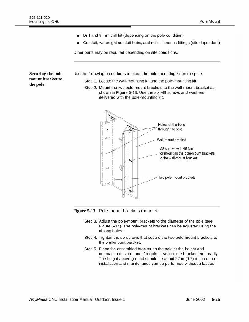
363-211-520Pole MountMounting the ONU
Drill and 9 mm drill bit (depending on the pole condition)
Conduit, watertight conduit hubs, and miscellaneous fittings (site dependent)
Other parts may be required depending on site conditions.
Securing the pole-mount bracket to the pole
Use the following procedures to mount he pole-mounting kit on the pole:
Step 1. Locate the wall-mounting kit and the pole-mounting kit.Step 2. Mount the two pole-mount brackets to the wall-mount bracket as
shown in Figure 5-13. Use the six M8 screws and washers delivered with the pole-mounting kit.
Figure 5-13 Pole-mount brackets mounted
Step 3. Adjust the pole-mount brackets to the diameter of the pole (see Figure 5-14). The pole-mount brackets can be adjusted using the oblong holes.
Step 4. Tighten the six screws that secure the two pole-mount brackets to the wall-mount bracket.
Step 5. Place the assembled bracket on the pole at the height and orientation desired, and if required, secure the bracket temporarily. The height above ground should be about 27 in (0.7) m to ensure installation and maintenance can be performed without a ladder.
;& )
8(& )
1" #&# +##
/, ((#!2" +#& )
#(& )
AnyMedia ONU Installation Manual: Outdoor, Issue 1 June 2002 5-25
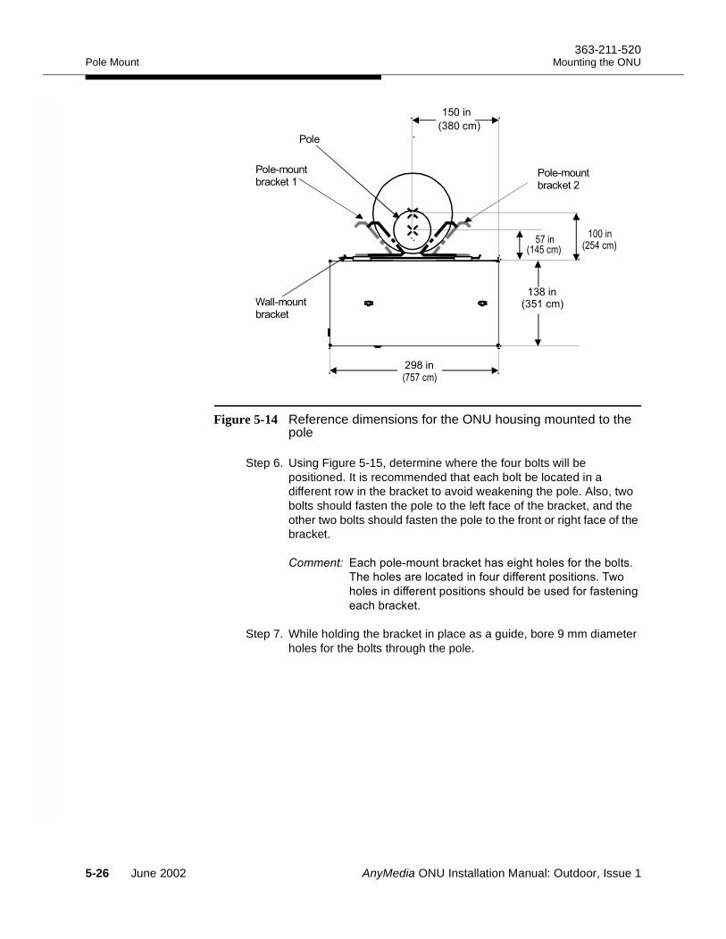
Pole Mount363-211-520
Mounting the ONU
Figure 5-14 Reference dimensions for the ONU housing mounted to the pole
Step 6. Using Figure 5-15, determine where the four bolts will be positioned. It is recommended that each bolt be located in a different row in the bracket to avoid weakening the pole. Also, two bolts should fasten the pole to the left face of the bracket, and the other two bolts should fasten the pole to the front or right face of the bracket.
()&!"+,$# '(.")"/))!"')" !
)")!"'"!("%#$'%"'"#&#-
)!"#%"'"#&#)$!% "$"%'"##/
"() '(."
Step 7. While holding the bracket in place as a guide, bore 9 mm diameter holes for the bolts through the pole.
0;6(,2
!!
!
'
' 4
' 4
7 4
07(,2
76#
!
;#
<;#
5-26 June 2002 AnyMedia ONU Installation Manual: Outdoor, Issue 1
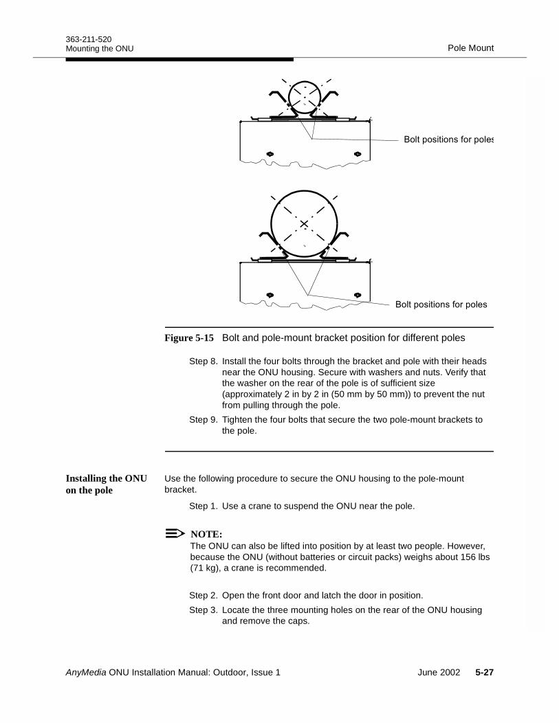
363-211-520Pole MountMounting the ONU
Figure 5-15 Bolt and pole-mount bracket position for different poles
Step 8. Install the four bolts through the bracket and pole with their heads near the ONU housing. Secure with washers and nuts. Verify that the washer on the rear of the pole is of sufficient size (approximately 2 in by 2 in (50 mm by 50 mm)) to prevent the nut from pulling through the pole.
Step 9. Tighten the four bolts that secure the two pole-mount brackets to the pole.
Installing the ONU on the pole
Use the following procedure to secure the ONU housing to the pole-mount bracket.
Step 1. Use a crane to suspend the ONU near the pole.
NOTE:The ONU can also be lifted into position by at least two people. However, because the ONU (without batteries or circuit packs) weighs about 156 lbs (71 kg), a crane is recommended.
Step 2. Open the front door and latch the door in position.Step 3. Locate the three mounting holes on the rear of the ONU housing
and remove the caps.
8!&#'&!"
8!&#'&!"
AnyMedia ONU Installation Manual: Outdoor, Issue 1 June 2002 5-27
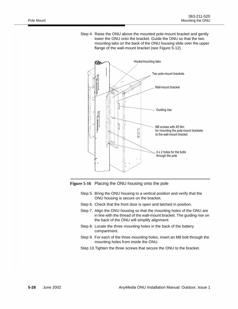
Pole Mount363-211-520
Mounting the ONU
Step 4. Raise the ONU above the mounted pole-mount bracket and gently lower the ONU onto the bracket. Guide the ONU so that the two mounting tabs on the back of the ONU housing slide over the upper flange of the wall-mount bracket (see Figure 5-12).
Figure 5-16 Placing the ONU housing onto the pole
Step 5. Bring the ONU housing to a vertical position and verify that the ONU housing is secure on the bracket.
Step 6. Check that the front door is open and latched in position.Step 7. Align the ONU housing so that the mounting holes of the ONU are
in line with the thread of the wall-mount bracket. The guiding rise on the back of the ONU will simplify alignment.
Step 8. Locate the three mounting holes in the back of the battery compartment.
Step 9. For each of the three mounting holes, insert an M8 bolt through the mounting holes from inside the ONU.
Step 10.Tighten the three screws that secure the ONU to the bracket.
8(& )
#" #&# +##
/, ((#!2" +#& )#(& )
1)+&
;& )
*+
5-28 June 2002 AnyMedia ONU Installation Manual: Outdoor, Issue 1

363-211-520Pole MountMounting the ONU
Step 11.Remove the B connecting link or clevis from each lifting eye of the cabinet. Move slings and boom line away from the cabinet.
Step 12.Proceed to Chapter 6 to continue the installation.
AnyMedia ONU Installation Manual: Outdoor, Issue 1 June 2002 5-29
Pole Mount363-211-520
Mounting the ONU
5-30 June 2002 AnyMedia ONU Installation Manual: Outdoor, Issue 1
AnyMedia ONU Installation Manual: Outdoor, Issue 1
Installing and Grounding External Cables 6Overview 6
This section describes the procedures for installing and grounding the signal and power cables required by the ONU
Contents
Page
Cabling Overview 6-3 Routing Cables for Pedestal-Mounted ONUs 6-4
Required materials 6-4Procedure 6-4
Routing Cables for Wall- and Pole-Mounted ONU 6-8Required materials 6-8Procedure 6-8
Connecting to the Site Ground 6-10Required materials 6-10Procedures 6-10
Grounding Subscriber Line Connections 6-13Copper cable 6-13Fiber Cable 6-14
June 2002 6-1

Overview363-211-520
Installing and Grounding External Cables
Grounding the AC Power Cable 6-17 Checking the Ground Connections 6-18 Sealing and Caulking the ONU Cables 6-19
Page
6-2 June 2002 AnyMedia ONU Installation Manual: Outdoor, Issue 1
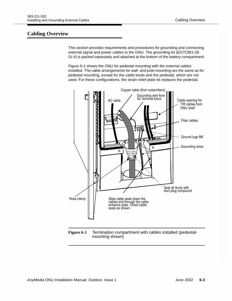
363-211-520Cabling OverviewInstalling and Grounding External Cables
Cabling Overview 6
This section provides requirements and procedures for grounding and connecting external signal and power cables to the ONU. The grounding kit (ED7C851-55 Gr.4) is packed separately and attached at the bottom of the battery compartment.
Figure 6-1 shows the ONU for pedestal mounting with the external cables installed. The cable arrangements for wall- and pole-mounting are the same as for pedestal mounting, except for the cable boots and the pedestal, which are not used. For these configurations, the strain relief plate kit replaces the pedestal.
Figure 6-1 Termination compartment with cables installed (pedestal-mounting shown)
1
* +( " 0 &)
* +(
* +/
<& &
0&+" 8.&" 52:#"
(#+
&(#&# +##& 5 &#(
0 &" & &
0&
AnyMedia ONU Installation Manual: Outdoor, Issue 1 June 2002 6-3
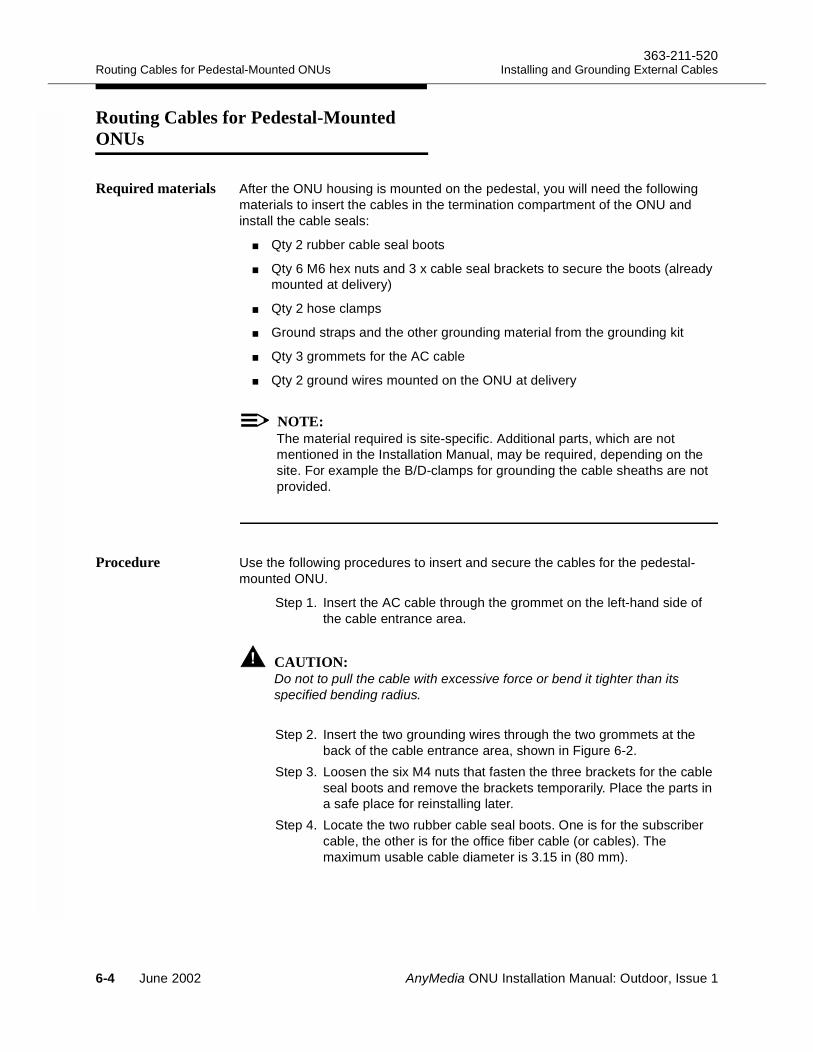
Routing Cables for Pedestal-Mounted ONUs363-211-520
Installing and Grounding External Cables
Routing Cables for Pedestal-Mounted ONUs 6
Required materials After the ONU housing is mounted on the pedestal, you will need the following materials to insert the cables in the termination compartment of the ONU and install the cable seals:
Qty2 rubber cable seal boots
Qty 6 M6 hex nuts and 3 x cable seal brackets to secure the boots (already mounted at delivery)
Qty 2 hose clamps
Ground straps and the other grounding material from the grounding kit
Qty 3 grommets for the AC cable
Qty 2 ground wires mounted on the ONU at delivery
NOTE:The material required is site-specific. Additional parts, which are not mentioned in the Installation Manual, may be required, depending on the site. For example the B/D-clamps for grounding the cable sheaths are not provided.
Procedure Use the following procedures to insert and secure the cables for the pedestal-mounted ONU.
Step 1. Insert the AC cable through the grommet on the left-hand side of the cable entrance area.
CAUTION:Do not to pull the cable with excessive force or bend it tighter than its specified bending radius.
Step 2. Insert the two grounding wires through the two grommets at the back of the cable entrance area, shown in Figure 6-2.
Step 3. Loosen the six M4 nuts that fasten the three brackets for the cable seal boots and remove the brackets temporarily. Place the parts in a safe place for reinstalling later.
Step 4. Locate the two rubber cable seal boots. One is for the subscriber cable, the other is for the office fiber cable (or cables). The maximum usable cable diameter is 3.15 in (80 mm).
6-4 June 2002 AnyMedia ONU Installation Manual: Outdoor, Issue 1
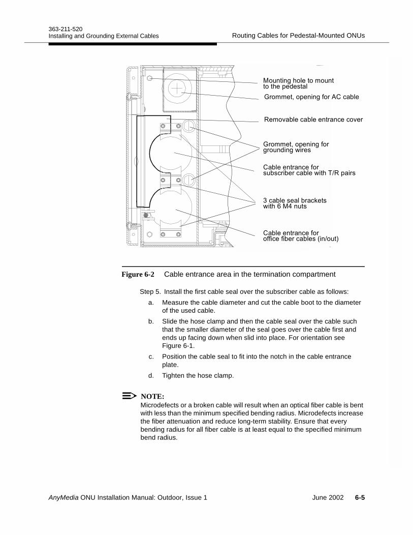
363-211-520Routing Cables for Pedestal-Mounted ONUsInstalling and Grounding External Cables
Figure 6-2 Cable entrance area in the termination compartment
Step 5. Install the first cable seal over the subscriber cable as follows:a. Measure the cable diameter and cut the cable boot to the diameter
of the used cable.b. Slide the hose clamp and then the cable seal over the cable such
that the smaller diameter of the seal goes over the cable first and ends up facing down when slid into place. For orientation see Figure 6-1.
c. Position the cable seal to fit into the notch in the cable entrance plate.
d. Tighten the hose clamp.
NOTE:Microdefects or a broken cable will result when an optical fiber cable is bent with less than the minimum specified bending radius. Microdefects increase the fiber attenuation and reduce long-term stability. Ensure that every bending radius for all fiber cable is at least equal to the specified minimum bend radius.
",= !"( !""#'#("(="'
',,"1&"##/'
!""#'#("'
/'$#%#/-'"
$ (' "'( !"-)5&'
!""#'#("'(" "'( !"0#5$2
$##/)!",$#)"&"%"!
',,"1&"##/' ( !"
( !""! '(."-)3#$
AnyMedia ONU Installation Manual: Outdoor, Issue 1 June 2002 6-5
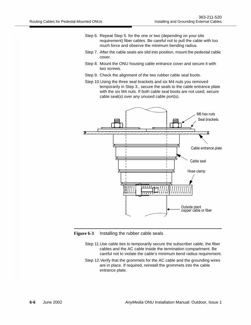
Routing Cables for Pedestal-Mounted ONUs363-211-520
Installing and Grounding External Cables
Step 6. Repeat Step 5. for the one or two (depending on your site requirement) fiber cables. Be careful not to pull the cable with too much force and observe the minimum bending radius.
Step 7. After the cable seals are slid into position, mount the pedestal cable cover.
Step 8. Mount the ONU housing cable entrance cover and secure it with two screws.
Step 9. Check the alignment of the two rubber cable seal boots. Step 10.Using the three seal brackets and six M4 nuts you removed
temporarily in Step 3., secure the seals to the cable entrance plate with the six M4 nuts. If both cable seal boots are not used, secure cable seal(s) over any unused cable port(s).
Figure 6-3 Installing the rubber cable seals
Step 11.Use cable ties to temporarily secure the subscriber cable, the fiber cables and the AC cable inside the termination compartment. Be careful not to violate the cable’s minimum bend radius requirement.
Step 12.Verify that the grommets for the AC cable and the grounding wires are in place. If required, reinstall the grommets into the cable entrance plate.
1
0&
0&
& )
/#
5 & "&
6-6 June 2002 AnyMedia ONU Installation Manual: Outdoor, Issue 1
363-211-520Routing Cables for Pedestal-Mounted ONUsInstalling and Grounding External Cables
NOTE:Sealing and caulking procedures are provided in Sealing and Caulking the ONU Cables. on page 6-19.
AnyMedia ONU Installation Manual: Outdoor, Issue 1 June 2002 6-7
Routing Cables for Wall- and Pole-Mounted ONU363-211-520
Installing and Grounding External Cables
Routing Cables for Wall- and Pole-Mounted ONU 6
Required materials After the ONU housing is mounted on a wall or pole, use the strain relief plate kit (ED7C851-55 Gr. 5) to install the cables in the termination compartment of the ONU and seal the cables:
NOTE:The material required is site-specific depending on the cables used on site. Additional parts not supplied by Lucent Technologies may be required.
Procedure When you have mounted the ONU and secured it to the wall or the pole, proceed as follows to mount the strain relief plate kit:
Step 1. Open the left door of the termination compartment and latch the door in position.
Step 2. Loosen the six M4 nuts that fasten the three seal brackets for the cable seal boots and remove the brackets. Place the six M4 nuts in a safe place for reinstallation later. The removed brackets are no longer needed for the pole- or wall-mounted ONU.
Step 3. Verify that the grommets for the AC cable and for the grounding wires are in place. Refer to Figure 6-2 for the positions of the grommets and cable entrance holes.
Step 4. Insert the AC power cable through the grommet on the left side of the cable entrance area.
Step 5. Insert the grounding wires through the two grommets at the back of the cable entrance area.
Step 6. Insert the copper subscriber T/R cable through the cable entrance hole in the center subscriber cable.
NOTE:Microdefects or a broken cable will result when an optical fiber cable is bent with less than the minimum specified bending radius. Microdefects increase the fiber attenuation and reduce long-term stability. Ensure that every bending radius for all fiber cable is at least equal to the specified minimum bend radius.
Step 7. Insert the fiber(s) and carefully pull the fibers, avoiding excessive force. Do not bend the fiber so that the bending radius is less than the minimum specified bending radius.
Step 8. Install the strain relief connectors on the AC cable, the copper cable and the fiber(s).
Step 9. Install the strain relief plate. You must route the AC cable, the copper cable and the fiber(s) through the openings in the plate.
6-8 June 2002 AnyMedia ONU Installation Manual: Outdoor, Issue 1
363-211-520Routing Cables for Wall- and Pole-Mounted ONUInstalling and Grounding External Cables
Step 10.Using the six M4 nuts removed in Step 2., fasten the strain relief plate on the six bolts that were used for the seal brackets.
Step 11.Install the sealing fittings on the AC cable, the copper cable and the fiber(s) and fasten to secure the cables.
Step 12.Use cable ties to temporarily secure the subscriber cable, the fiber cables and the AC cable. Be careful not to violate the cable’s minimum bending radius requirement.
Step 13.Check that the grommets for the AC cable and the grounding wires are in place. If required reinstall the grommets into the cable entrance plate.
NOTE:The complete sealing/caulking is described in Sealing and Caulking the ONU Cables on page 6-19.
AnyMedia ONU Installation Manual: Outdoor, Issue 1 June 2002 6-9
Connecting to the Site Ground363-211-520
Installing and Grounding External Cables
Connecting to the Site Ground 6
For pedestal-mounted ONUs, the site grounding system is normally installed beneath the foundation pad before the concrete is poured, as described in Pedestal Mount on page 5-17. At least 1 m of ground wire is required above the pad for both rods A and B (refer to Figure 4 on page 4-2) so that the wires reach the M6 grounding studs inside the ONU. After the pad is constructed and the pedestal and the ONU are mounted on the pad, use the procedures in this section to connect the ONU housing to the site ground wires.
Pole-, and wall-mounted ONUs are grounded in a similar manner, but the above-ground portion of the ground wires must be longer than 1 m to reach the M6 grounding studs. A non-metallic conduit may be required to protect the ground wires when the cabinet is mounted above the ground level.
Required materials The following materials will be needed to connect the grounding studs inside the ONU to the site grounding wires:
2 double-hole lugs (for 16 mm2/6 AWG wire), which are either part of the grounding kit ED7C851-55 Gr.4 or are already mounted on the grounding studs
12 washers and nuts, which are already mounted on the grounding studs
NOTE:The material required is site-specific and depend on the cables used. Additional parts not supplied by Lucent Technologies may be required.
WARNING:The installation must have an independent ground connection to an approved ground electrode for outdoor applications. Grounding circuit continuity is vital for safe operation of the ONU.
The independent ground connection should be at least 16 mm2) or ≤ 6 AWG.
If rod-based grounding is required two rods should be used.
Never operate the ONU with a disconnected ground.
Procedures To ground the ONU housing proceed, as follows.
Step 1. Locate the two customer-provided 16 mm2/6 AWG solid copper ground wires from ground rod A and B (routed through the rear grommets in the cable entrance area).
6-10 June 2002 AnyMedia ONU Installation Manual: Outdoor, Issue 1
363-211-520Connecting to the Site GroundInstalling and Grounding External Cables
NOTE:Two mechanical double-hole lugs are delivered for connecting a 0.025 in2 (16 mm2 ) round conductor, as typically used with a driven ground rod. If your installation includes a ground conductor with a larger cross section, substitute a suitable lug. For example, if your site ground is a ground ring, the ground conductor is typically 0.054 in2 (35 mm2).
Step 2. Cut the ground wires to an appropriate length to reach the M6 grounding studs. Remove the sheath, as required, and crimp the double-hole lugs.
Step 3. Connect the ground wires to the M6 grounding studs on the ONU ground bus. Fasten the M6 double-hole cable lugs at the grounding studs with the external toothed lock washer and the M6 hexagonal nut; see Figure 6-4, page 6-12 for mounting.
Step 4. Connect a ground wire 16 mm2/6 AWG).Step 5. from the M6 grounding stud to the ground terminal in the AC
termination box.Step 6. If the Krone cross-connect is already installed, connect the two
grounding wires coming from the cross-connect rods to an M6 ground stud.
NOTE:The conductive members of the cabinet structure are made of aluminum which has been chemically oxidized to provide a conductive finish. Installer ground connections should be made using only copper or aluminum lugs that are silver- or tin-plated. Unplated copper lugs are not recommended.
AnyMedia ONU Installation Manual: Outdoor, Issue 1 June 2002 6-11
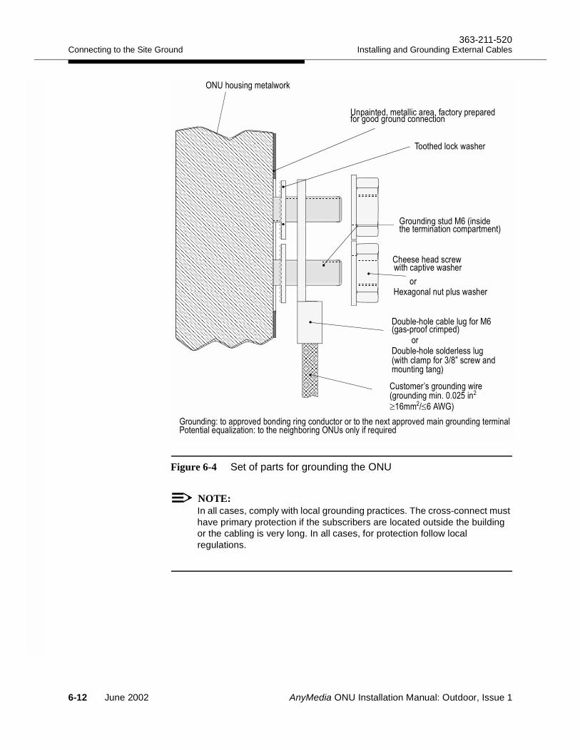
Connecting to the Site Ground363-211-520
Installing and Grounding External Cables
Figure 6-4 Set of parts for grounding the ONU
NOTE:In all cases, comply with local grounding practices. The cross-connect must have primary protection if the subscribers are located outside the building or the cabling is very long. In all cases, for protection follow local regulations.
0 =+ +(
* +/
0## (
:% %" '
* +> $&+ + # $+ +
+ +!
6?->#+#& +52:'" ?
52:#+( )
#
" ++
8#)(#
1 +(#
4&#&+" /+ "
++
(#$(#
(#" ,@ (4&# +
≥≤ ;*
6-12 June 2002 AnyMedia ONU Installation Manual: Outdoor, Issue 1
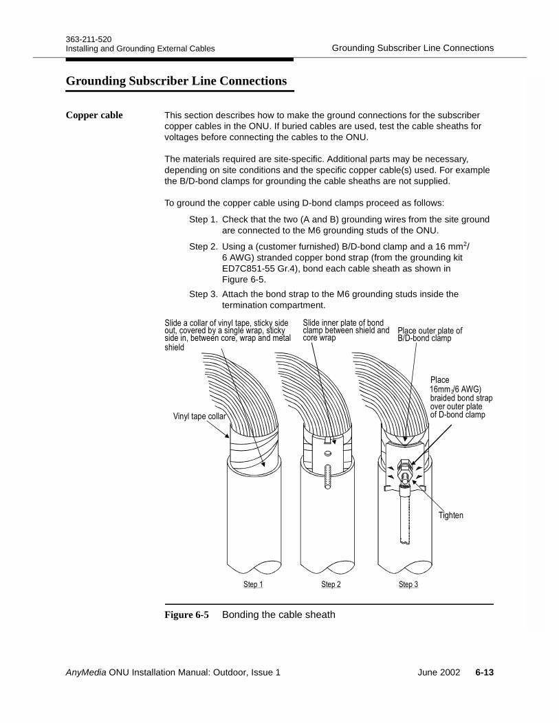
363-211-520Grounding Subscriber Line ConnectionsInstalling and Grounding External Cables
Grounding Subscriber Line Connections6
Copper cable This section describes how to make the ground connections for the subscriber copper cables in the ONU. If buried cables are used, test the cable sheaths for voltages before connecting the cables to the ONU.
The materials required are site-specific. Additional parts may be necessary, depending on site conditions and the specific copper cable(s) used. For example the B/D-bond clamps for grounding the cable sheaths are not supplied.
To ground the copper cable using D-bond clamps proceed as follows:
Step 1. Check that the two (A and B) grounding wires from the site ground are connected to the M6 grounding studs of the ONU.
Step 2. Using a (customer furnished) B/D-bond clamp and a 16 mm2/6 AWG) stranded copper bond strap (from the grounding kit ED7C851-55 Gr.4), bond each cable sheath as shown in Figure 6-5.
Step 3. Attach the bond strap to the M6 grounding studs inside the termination compartment.
Figure 6-5 Bonding the cable sheath
7'
6 "34&
& & $ "4&
8+#
"&&(# (
"$'%)'%$ &'+( %)'%&( %(
6;*
#
AnyMedia ONU Installation Manual: Outdoor, Issue 1 June 2002 6-13
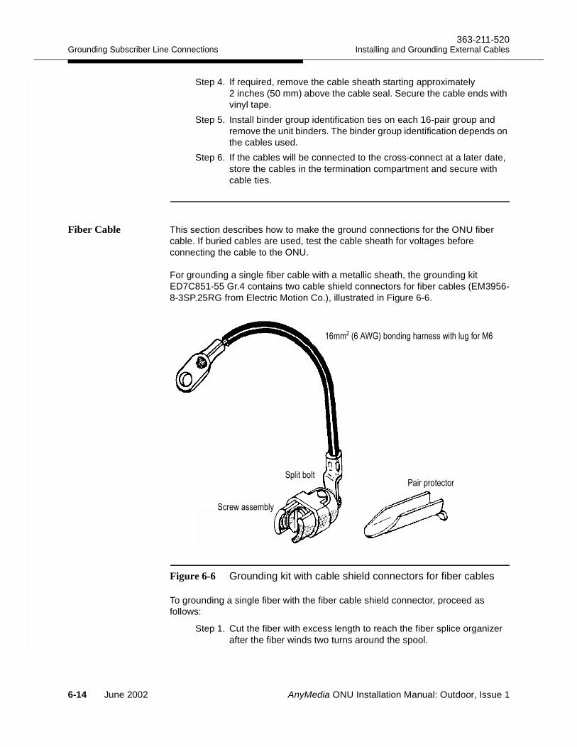
Grounding Subscriber Line Connections363-211-520
Installing and Grounding External Cables
Step 4. If required, remove the cable sheath starting approximately 2 inches (50 mm) above the cable seal. Secure the cable ends with vinyl tape.
Step 5. Install binder group identification ties on each 16-pair group and remove the unit binders. The binder group identification depends on the cables used.
Step 6. If the cables will be connected to the cross-connect at a later date, store the cables in the termination compartment and secure with cable ties.
Fiber Cable This section describes how to make the ground connections for the ONU fiber cable. If buried cables are used, test the cable sheath for voltages before connecting the cable to the ONU.
For grounding a single fiber cable with a metallic sheath, the grounding kit ED7C851-55 Gr.4 contains two cable shield connectors for fiber cables (EM3956-8-3SP.25RG from Electric Motion Co.), illustrated in Figure 6-6.
Figure 6-6 Grounding kit with cable shield connectors for fiber cables
To grounding a single fiber with the fiber cable shield connector, proceed as follows:
Step 1. Cut the fiber with excess length to reach the fiber splice organizer after the fiber winds two turns around the spool.
;*&+# (#+" /
6
(&'
&
6-14 June 2002 AnyMedia ONU Installation Manual: Outdoor, Issue 1
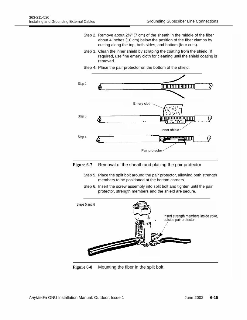
363-211-520Grounding Subscriber Line ConnectionsInstalling and Grounding External Cables
Step 2. Remove about 2¾” (7 cm) of the sheath in the middle of the fiber about 4 inches (10 cm) below the position of the fiber clamps by cutting along the top, both sides, and bottom (four cuts).
Step 3. Clean the inner shield by scraping the coating from the shield. If required, use fine emery cloth for cleaning until the shield coating is removed.
Step 4. Place the pair protector on the bottom of the shield.
Figure 6-7 Removal of the sheath and placing the pair protector
Step 5. Place the split bolt around the pair protector, allowing both strength members to be positioned at the bottom corners.
Step 6. Insert the screw assembly into split bolt and tighten until the pair protector, strength members and the shield are secure.
Figure 6-8 Mounting the fiber in the split bolt
,"'*(!)
'&'"('
##"')"!%
!
9 +#& ')%
AnyMedia ONU Installation Manual: Outdoor, Issue 1 June 2002 6-15

Grounding Subscriber Line Connections363-211-520
Installing and Grounding External Cables
Step 7. Fix the fibers into the fiber clamps directly below the fiber splice organizer.
Step 8. Connect the bonding harness to one of the M6 grounding studs.
6-16 June 2002 AnyMedia ONU Installation Manual: Outdoor, Issue 1
363-211-520Grounding the AC Power CableInstalling and Grounding External Cables
Grounding the AC Power Cable 6
If the AC power cable is shielded, connect the sheath to one of the M6 grounding studs.
If buried cables are used, test the cable sheaths for voltages before connecting the AC power cable to the ONU.
NOTE:The material required is site-specific and depend on site conditions and the AC cable used. Always use the appropriate grounding material designated for the AC cable used. Follow local practices.
AnyMedia ONU Installation Manual: Outdoor, Issue 1 June 2002 6-17
Checking the Ground Connections363-211-520
Installing and Grounding External Cables
Checking the Ground Connections 6
After grounding, the connection from the framework to the bonding ring conductor must be checked/measured according to local regulations.
Proceed as follows:
Step 1. Verify that no AnyMedia packs are inserted in the ONU shelf. Step 2. The connection from the framework to the bonding ring conductor
must be measured according to local regulations.Step 3. Ensure the electrical continuity of the connections between:
a. FRMGND (framework)b. approved ground electrode/terminal c. framework of adjacent ONU housingsd. cable sheaths.
NOTE:Under normal operational conditions, voltages above about 1 V are not allowed between the ground wire and the grounding points mentioned above.
Step 4. If required measure the grounding resistance according to local regulations.
6-18 June 2002 AnyMedia ONU Installation Manual: Outdoor, Issue 1
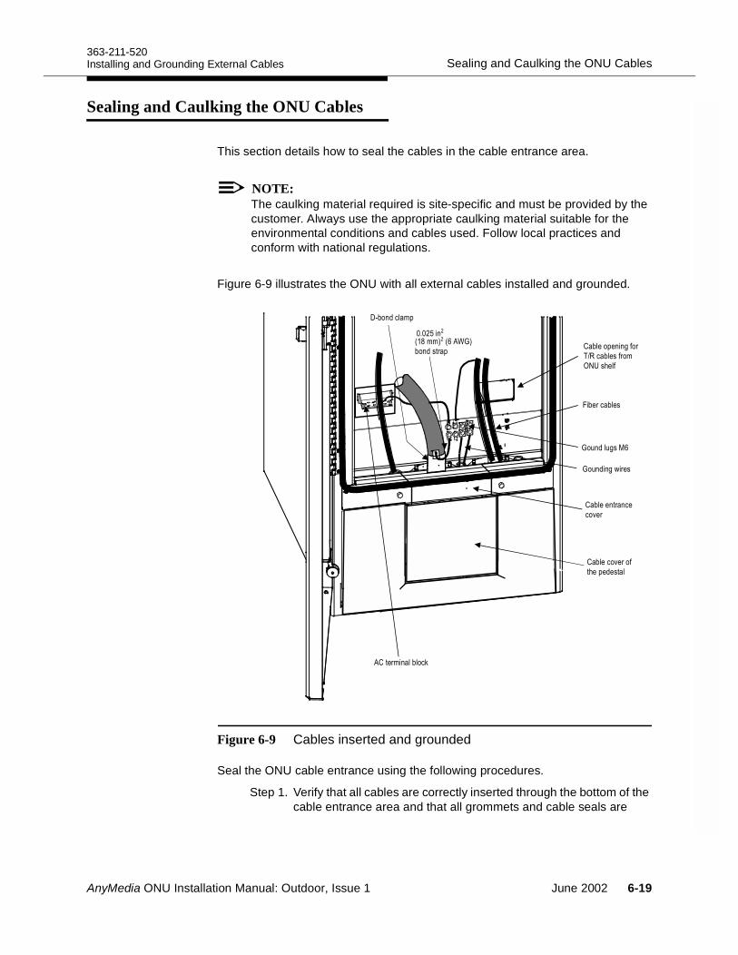
363-211-520Sealing and Caulking the ONU CablesInstalling and Grounding External Cables
Sealing and Caulking the ONU Cables 6
This section details how to seal the cables in the cable entrance area.
NOTE:The caulking material required is site-specific and must be provided by the customer. Always use the appropriate caulking material suitable for the environmental conditions and cables used. Follow local practices and conform with national regulations.
Figure 6-9 illustrates the ONU with all external cables installed and grounded.
Figure 6-9 Cables inserted and grounded
Seal the ONU cable entrance using the following procedures.
Step 1. Verify that all cables are correctly inserted through the bottom of the cable entrance area and that all grommets and cable seals are
0&$ "
#
0&
$
0 &)
*+(
*+/
<& &
0&+"
8.&"
52:#"
4&
,;*
&
!
AnyMedia ONU Installation Manual: Outdoor, Issue 1 June 2002 6-19
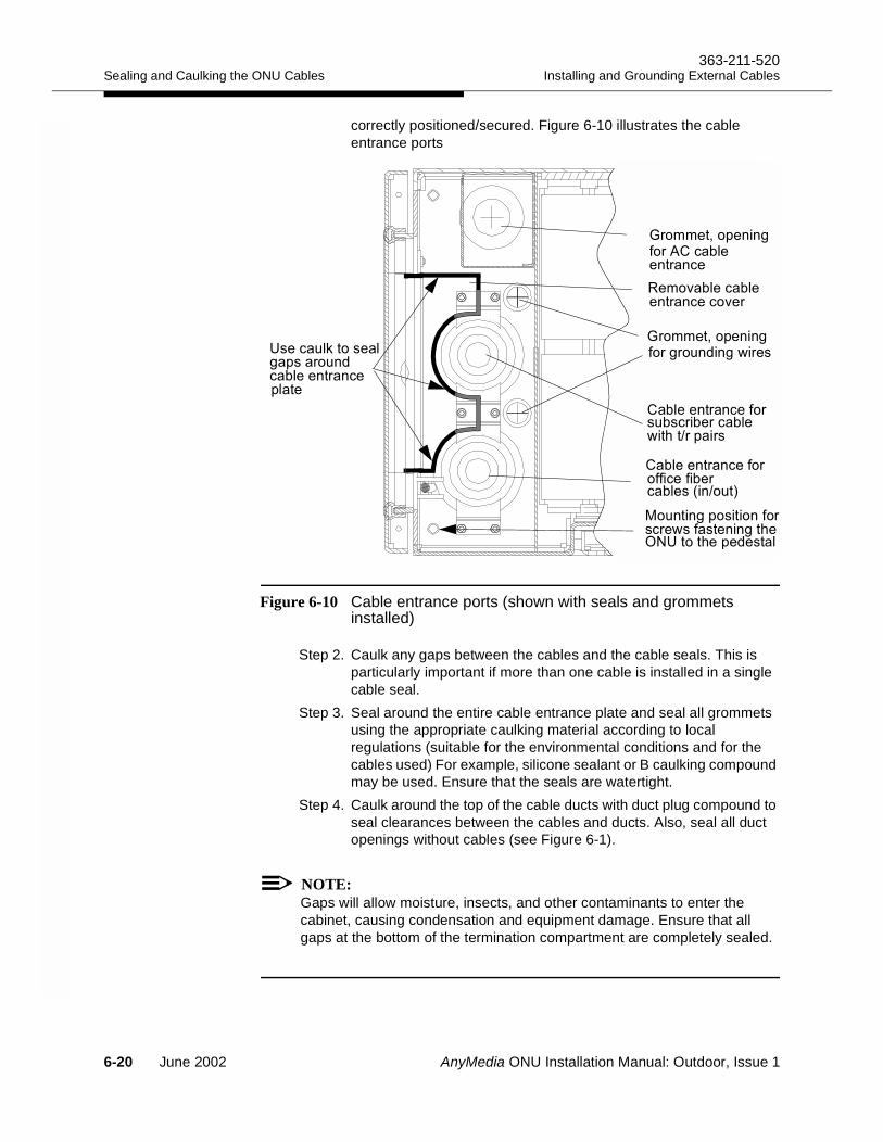
Sealing and Caulking the ONU Cables363-211-520
Installing and Grounding External Cables
correctly positioned/secured. Figure 6-10 illustrates the cable entrance ports
Figure 6-10 Cable entrance ports (shown with seals and grommets installed)
Step 2. Caulk any gaps between the cables and the cable seals. This is particularly important if more than one cable is installed in a single cable seal.
Step 3. Seal around the entire cable entrance plate and seal all grommets using the appropriate caulking material according to local regulations (suitable for the environmental conditions and for the cables used) For example, silicone sealant or B caulking compound may be used. Ensure that the seals are watertight.
Step 4. Caulk around the top of the cable ducts with duct plug compound to seal clearances between the cables and ducts. Also, seal all duct openings without cables (see Figure 6-1).
NOTE:Gaps will allow moisture, insects, and other contaminants to enter the cabinet, causing condensation and equipment damage. Ensure that all gaps at the bottom of the termination compartment are completely sealed.
",= !"( !"
',,"1&"##/
!""#'#("'$ (' "'( !"
!""#'#("'(" "'
',,"1&"##/
"#'#("
"#'#("(="'
-)5'&'
"($!."!/&'$#%( !""#'#("&!"
$##/&#'('"-"##/)"
'/'$#%#/-'"
' ( !"
( !"0#5$2
)"&"%"!
6-20 June 2002 AnyMedia ONU Installation Manual: Outdoor, Issue 1
AnyMedia ONU Installation Manual: Outdoor, Issue 1
Connecting the Signal Lines 7Overview 7
This chapter provides the procedures for installing the ONU copper and fiber signal cables. Personnel experienced with the ONU may skip to 7-13.
Contents
Page
Signal Cabling and Wiring Overview 7-3Internal cables 7-3External cable(s) from the subscribers 7-3Cross connecting the feeder and distribution sides 7-4Primary protection 7-4
ONU Cable Reference 7-5Cable routing 7-6Cable diagrams 7-7Cable connection table 7-11
Cable Installation and Wiring Procedures 7-13Checking the grounding 7-13Checking the delivered cabling 7-13Setting the ONU shelf identifier 7-14Installing the Krone cross-connect 7-15Marking the TAP100 cable (option) 7-16Interconnecting the test application paths (option) 7-16Installing the customer copper cables 7-18
June 2002 7-1
Overview363-211-520
Connecting the Signal Lines
Installing the cross-connect jumper wires 7-20Rerouting cross-connections for the ADSL service 7-21
Wiring of Connectors and Connecting Points of the ONU shelf
7-23
Connectors of the ONU shelf connection panel (SCP) 7-23 Installing the Fiber 7-25
Fiber installation overview 7-25Fiber link configuration 7-25Optical link interface 7-25Installing the fiber at the remote AnyMedia FAST shelf 7-26Cleaning optical connectors and couplings 7-27Fiber cabling at the ONU 7-27
Page
7-2 June 2002 AnyMedia ONU Installation Manual: Outdoor, Issue 1
363-211-520Signal Cabling and Wiring OverviewConnecting the Signal Lines
Signal Cabling and Wiring Overview 7
ONU cables are classified as:
Internal cables/wiring that connect the assemblies within the ONU
External cables that connect to facilities outside the ONU housing, such as the customer’s equipment and the AC power supply.
Internal cables The ONU is delivered with all internal cables in place, many of which are pre-connected. You will be required, however, to complete the connections for the:
Base Housing Configuration 7
The ONU is delivered in the base housing configuration (ED7C851-50 Gr.x) without the pre-installed Krone cross-connect, and you must mount the cross-connect. Mounting instructions are provided in Mounting and Installing the Optional Cross-Connect on page 5-3. Figure 5-2, page 5-5 shows you how to route the T/R cables and the optional TAP-B and TAP100 cables to the Krone cross-connect for combined POTS and xDSL applications.
Normally the eight T/R-cables and the TAP-B cable from the ONU shelf are pre-installed at delivery and are fixed in the cross-connect area. Instructions for connecting the T/R cables to the feeder side of the internal Krone cross-connect are provided in “Connecting T/R-cables for the base housing configuration” on page 5-9.
TAP cross wiring 7
If the metallic test feature is supported, make the following connections for the metallic test feature:
TAP-B
TAP100 AP
See 'Interconnecting the test application paths (option)” on page 7-16. The cross-connect assignment for these interconnections is provided in Table 7-2., page 7-18.
External cable(s) from the subscribers
Connect the customer’s equipment to the distribution side of the internal cross-connect according to the work order or the instructions of the network provider. See “Installing the customer copper cables” on page 7-18.
AnyMedia ONU Installation Manual: Outdoor, Issue 1 June 2002 7-3
Signal Cabling and Wiring Overview363-211-520
Connecting the Signal Lines
NOTE:On the distribution side, normal 10-pair LSA PLUS 2/10 disconnection blocks are used, which must be cabled from the top connecting points to the customer’s copper cabling so that the lower connecting points of the block can be used for the crosswiring to the feeder side.
Cross connecting the feeder and distribution sides
The feeder side and the distribution side of the cross-connect must be crosswired with jumper wires according to the work order or the instructions of the network provider. Procedures for crosswiring are provided in “Installing the cross-connect jumper wires” on page 7-20.
Primary protection The distribution side must be primary protected with protection magazines such as those equipped with 3-point gas-filled arrestors, for example. For the position of the protector magazines, see Figure 7-1 on page 7-6.
7-4 June 2002 AnyMedia ONU Installation Manual: Outdoor, Issue 1
363-211-520ONU Cable ReferenceConnecting the Signal Lines
ONU Cable Reference 7
The following drawings of the ONU internal and external cables illustrate the cabling and wiring procedures described in this chapter:
Figure 7-1 illustrates the cables in the ONU termination compartment. The external cables shown entering the ONU termination compartment through the cable entrance at the bottom are the cables that you connect to the ONU during the installation process.
Figure 7-2 illustrates the cable arrangement for the ONU shelf.
Figure 7-3 is a schematic diagram of the cabling located inside the ONU electronics compartment.
Figure 7-4 illustrates the physical connections of the cables inside the electronics compartment.
Figure 7-5 illustrates the physical connections of the cables inside the termination compartment.
Table 7-1 summarizes all the ONU cable connections.
AnyMedia ONU Installation Manual: Outdoor, Issue 1 June 2002 7-5
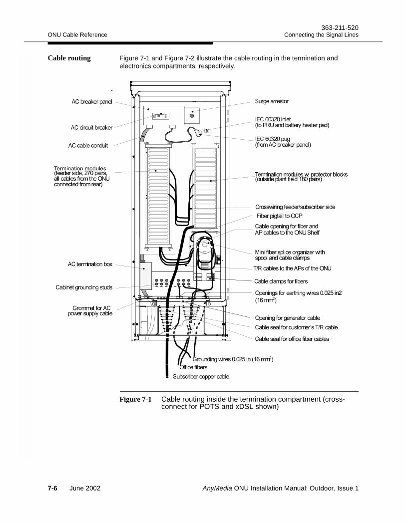
ONU Cable Reference363-211-520
Connecting the Signal Lines
Cable routing Figure 7-1 and Figure 7-2 illustrate the cable routing in the termination and electronics compartments, respectively.
Figure 7-1 Cable routing inside the termination compartment (cross-connect for POTS and xDSL shown)
+(,
-(.+/0(
1(2
!&#
"',##,%$!" '3'
4-(, 5
$6- "7 4-(,#
$6- "7 0(8#
-((4( 5
4-(,
4-(
4-(
-(
(
-((
-(((
( #
94-8(
9 !"2
(
5(((
+/0(4
-/((
:(-
(
!"2
7-6 June 2002 AnyMedia ONU Installation Manual: Outdoor, Issue 1
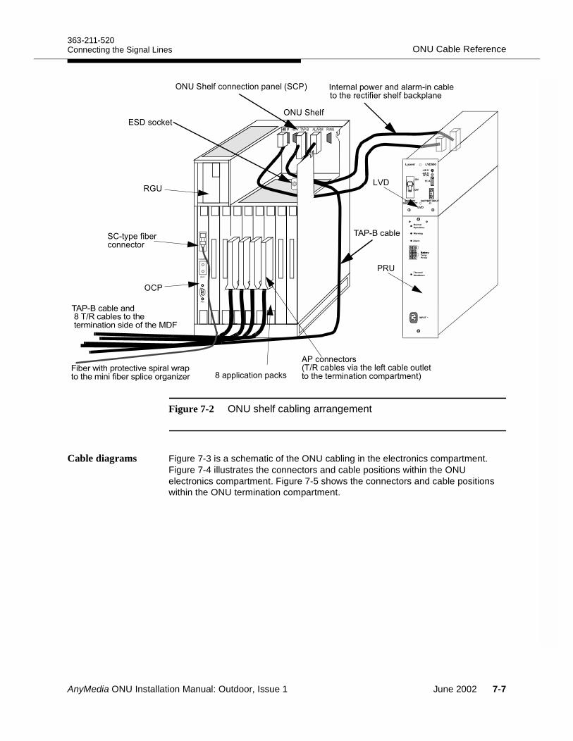
363-211-520ONU Cable ReferenceConnecting the Signal Lines
Figure 7-2 ONU shelf cabling arrangement
Cable diagrams Figure 7-3 is a schematic of the ONU cabling in the electronics compartment. Figure 7-4 illustrates the connectors and cable positions within the ONU electronics compartment. Figure 7-5 shows the connectors and cable positions within the ONU termination compartment.
)"!(##"(#&#"!02 #"'#!&-"'#%!',+#( !"
;&&!(#&(.
(##"('05( !"=)"!"( !"$!")""',##(,&',"#2
)"'"("')"! (.&!#"
./0
0123.4*
4.56
+*&" "'(##"('
(.")"!
, 7 863 ./ .92*, 7 , 7
?
AnyMedia ONU Installation Manual: Outdoor, Issue 1 June 2002 7-7
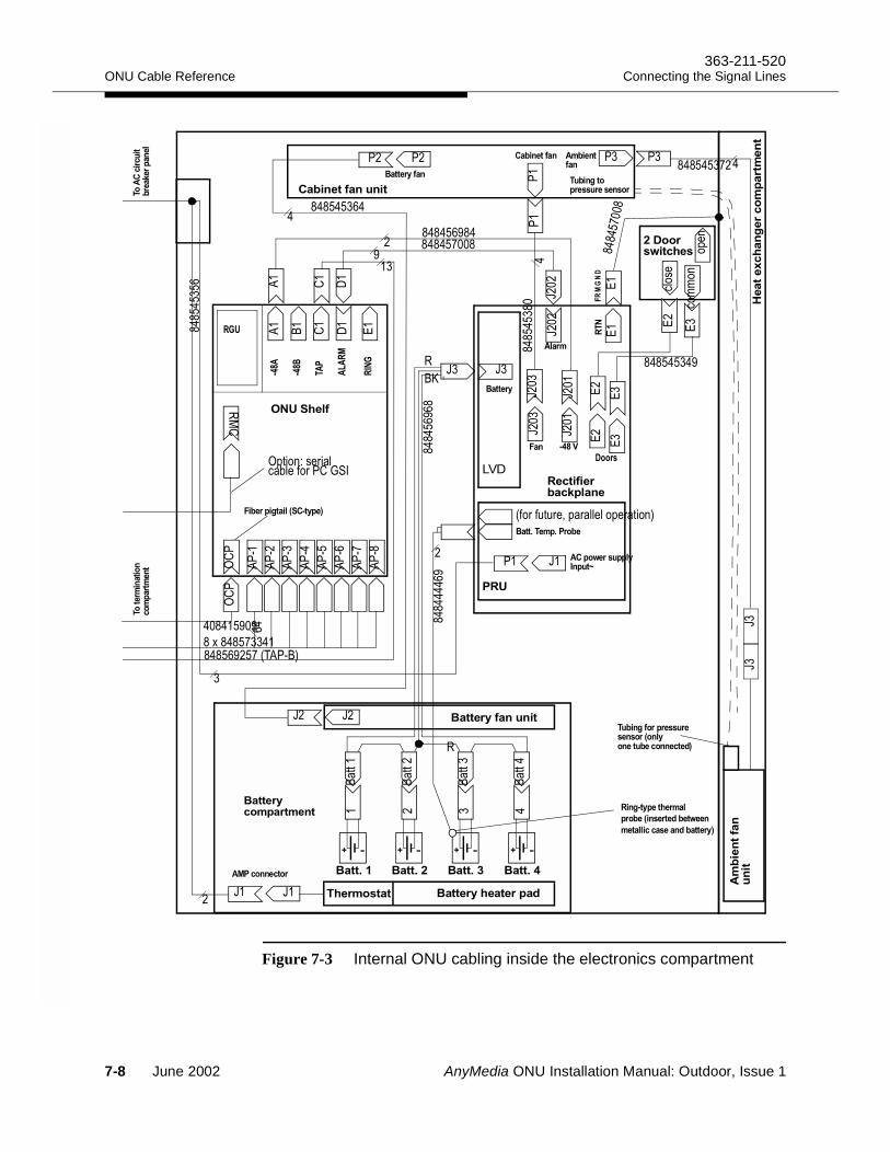
ONU Cable Reference363-211-520
Connecting the Signal Lines
Figure 7-3 Internal ONU cabling inside the electronics compartment
3
0
A
B
B
B
B
A
A
A
A
A
A
B
B
B B
50
65
06
3
3
3
3
B
6
,
6
6
6
!
6
6
6
6
!
A
,,!!
,,!!
./
0
, ,,!
5>
!"#
,,
!
,,
,
,,!,,,!,
"
#
$$#!
,,
!
,
0
,,!!863
" " %
A
3C
.
.
6
BB
BB $#%#
$"&
6
6
6 6
' ##%#
66
%&
BB
() ##
%#
*+#,)")#
4
4
'
$$#!
,,!!
,,!
!,
($$
,!
&" 60*9
,,!
!!
$
$$
)
-)
'
' '
7-8 June 2002 AnyMedia ONU Installation Manual: Outdoor, Issue 1
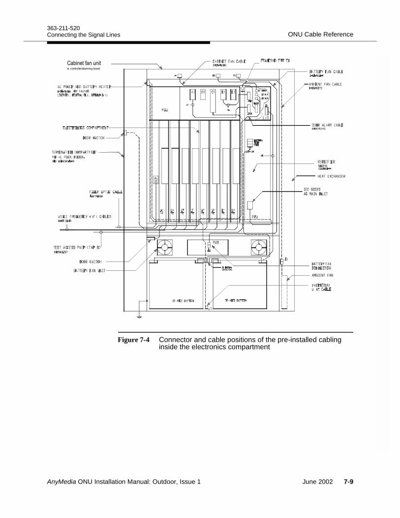
363-211-520ONU Cable ReferenceConnecting the Signal Lines
Figure 7-4 Connector and cable positions of the pre-installed cabling inside the electronics compartment
0&"( +&
AnyMedia ONU Installation Manual: Outdoor, Issue 1 June 2002 7-9
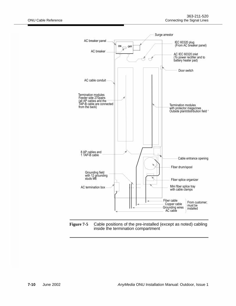
ONU Cable Reference363-211-520
Connecting the Signal Lines
Figure 7-5 Cable positions of the pre-installed (except as noted) cabling inside the termination compartment
0& )
0& )
0&
+
* * < 0& )
8( " & '#
9A0+
09A0
4 (#
5 &"
8 (# +-
0& +
/"& '(#&
8
* +"(#+ +
0 &
<& &0 &
* +( 0&
< D&
< 6͟&
,6&863&
" #&)
/
<&
<& +-
7-10 June 2002 AnyMedia ONU Installation Manual: Outdoor, Issue 1
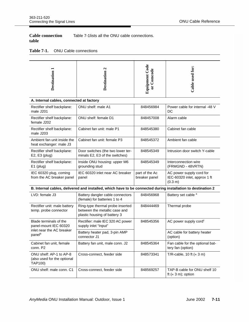
363-211-520ONU Cable ReferenceConnecting the Signal Lines
Cable connection table
Table 7-1lists all the ONU cable connections.
Table 7-1. ONU Cable connectionsD
estin
atio
n 1
Des
tinat
ion
2
Equ
ipm
ent C
ode
or C
omco
de
Cab
le u
sed
for:
A. Internal cables, connected at factory
Rectifier shelf backplane: male J201
ONU shelf: male A1 848456984 Power cable for internal -48 V DC
Rectifier shelf backplane: female J202
ONU shelf: female D1 848457008 Alarm cable
Rectifier shelf backplane: male J203
Cabinet fan unit: male P1 848545380 Cabinet fan cable
Ambient fan unit inside the heat exchanger: male J3
Cabinet fan unit: female P3 848545372 Ambient fan cable
Rectifier shelf backplane: E2, E3 (plug)
Door switches (the two lower ter-minals E2, E3 of the switches)
848545349 Intrusion door switch Y-cable
Rectifier shelf backplane: E1 (plug)
Inside ONU housing: upper M6 grounding stud
848545349 Interconnection wire (FRMGND - 48VRTN)
IEC 60320 plug, coming from the AC breaker panel
IEC 60320 inlet near AC breaker panel
part of the Ac breaker panel
AC power supply cord for IEC-60320 inlet, approx 1 ft (0.3 m)
B. Internal cables, delivered and installed, which have to be connected during installation to destination 2LVD: female J3 Battery dangler cable connectors
(female) for batteries 1 to 4 848456968 Battery set cable a
Rectifier unit: male battery temp. probe connector
Ring-type thermal probe inserted between the metallic case and plastic housing of battery 3
848444469 Thermal probe
Blade terminals of the panel-mount IEC 60320 inlet near the AC breaker panelb
Rectifier: male IEC 320 AC power supply inlet “Input”
848545356 AC power supply cordc
Battery heater pad, 3-pin AMP connector J1
AC cable for battery heater(option)
Cabinet fan unit, female conn. P2
Battery fan unit, male conn. J2 848545364 Fan cable for the optional bat-tery fan (option)
ONU shelf: AP-1 to AP-8 (also used for the optional TAP100)
Cross-connect, feeder side 848573341 T/R-cable, 10 ft (≈ 3 m)
ONU shelf: male conn. C1 Cross-connect, feeder side 848569257 TAP-B cable for ONU shelf 10 ft (≈ 3 m); option
AnyMedia ONU Installation Manual: Outdoor, Issue 1 June 2002 7-11
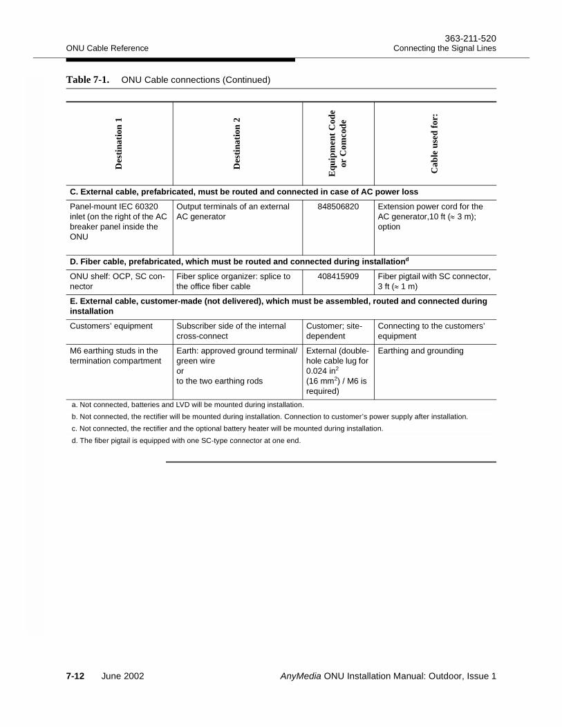
ONU Cable Reference363-211-520
Connecting the Signal Lines
C. External cable, prefabricated, must be routed and connected in case of AC power loss
Panel-mount IEC 60320 inlet (on the right of the AC breaker panel inside the ONU
Output terminals of an external AC generator
848506820 Extension power cord for the AC generator,10 ft (≈ 3 m); option
D. Fiber cable, prefabricated, which must be routed and connected during installationd
ONU shelf: OCP, SC con-nector
Fiber splice organizer: splice to the office fiber cable
408415909 Fiber pigtail with SC connector, 3 ft (≈ 1 m)
E. External cable, customer-made (not delivered), which must be assembled, routed and connected during installationCustomers’ equipment Subscriber side of the internal
cross-connectCustomer; site-dependent
Connecting to the customers’ equipment
M6 earthing studs in the termination compartment
Earth: approved ground terminal/green wireorto the two earthing rods
External (double-hole cable lug for 0.024 in2 (16 mm2) / M6 is required)
Earthing and grounding
a. Not connected, batteries and LVD will be mounted during installation.b. Not connected, the rectifier will be mounted during installation. Connection to customer’s power supply after installation.c. Not connected, the rectifier and the optional battery heater will be mounted during installation.d. The fiber pigtail is equipped with one SC-type connector at one end.
Table 7-1. ONU Cable connections (Continued)
Des
tinat
ion
1
Des
tinat
ion
2
Equ
ipm
ent C
ode
or C
omco
de
Cab
le u
sed
for:
7-12 June 2002 AnyMedia ONU Installation Manual: Outdoor, Issue 1
363-211-520Cable Installation and Wiring ProceduresConnecting the Signal Lines
Cable Installation and Wiring Procedures7
This section describes each of the ONU cable installation procedures.
Checking the grounding
If you have not already done so, before beginning the cable installation, verify the ONU grounding integrity as follows:
Step 1. Open the door of the termination compartment of the ONU.Step 2. Measure the connection from the framework to the approved
earthing terminal according to local regulations.Step 3. Ensure the electrical continuity of the connections among the
following:a. FRMGND (framework)b. Approved ground conductor/terminal to which the grounding wire is
connectedc. Framework of adjacent ONU housings if mountedd. All cable sheaths
NOTE:Voltages on ground circuits should be less than 1 V.
Step 4. If required measure the grounding resistance according to local regulations.
Checking the delivered cabling
Check the delivered cabling as follows:
Step 1. Verify that the visible factory wiring is free of broken, bent or misaligned connectors.
Step 2. Verify that all factory wiring is secure and tied into form.Step 3. Verify that all cables are mountedStep 4. Verify that all connectors are connected and secured. Fasten loose
cables, as required.
NOTE:Refer to label information attached to the ONU door of the electronics compartment to determine where cables should be connected.
AnyMedia ONU Installation Manual: Outdoor, Issue 1 June 2002 7-13
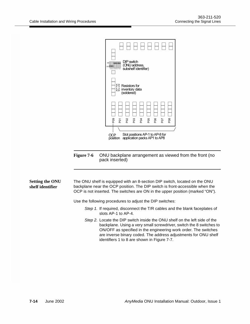
Cable Installation and Wiring Procedures363-211-520
Connecting the Signal Lines
Figure 7-6 ONU backplane arrangement as viewed from the front (no pack inserted)
Setting the ONU shelf identifier
The ONU shelf is equipped with an 8-section DIP switch, located on the ONU backplane near the OCP position. The DIP switch is front-accessible when the OCP is not inserted. The switches are ON in the upper position (marked “ON”).
Use the following procedures to adjust the DIP switches:
Step 1. If required, disconnect the T/R cables and the blank faceplates of slots AP-1 to AP-4.
Step 2. Locate the DIP switch inside the ONU shelf on the left side of the backplane. Using a very small screwdriver, switch the 8 switches to ON/OFF as specified in the engineering work order. The switches are inverse binary coded. The address adjustments for ONU shelf identifiers 1 to 8 are shown in Figure 7-7.
- 54;!4;&
6
6
6
6
67
63
6:
6;
6<
*$5<<
52
! ,
'(#
,4!4&
0<8
#
7-14 June 2002 AnyMedia ONU Installation Manual: Outdoor, Issue 1
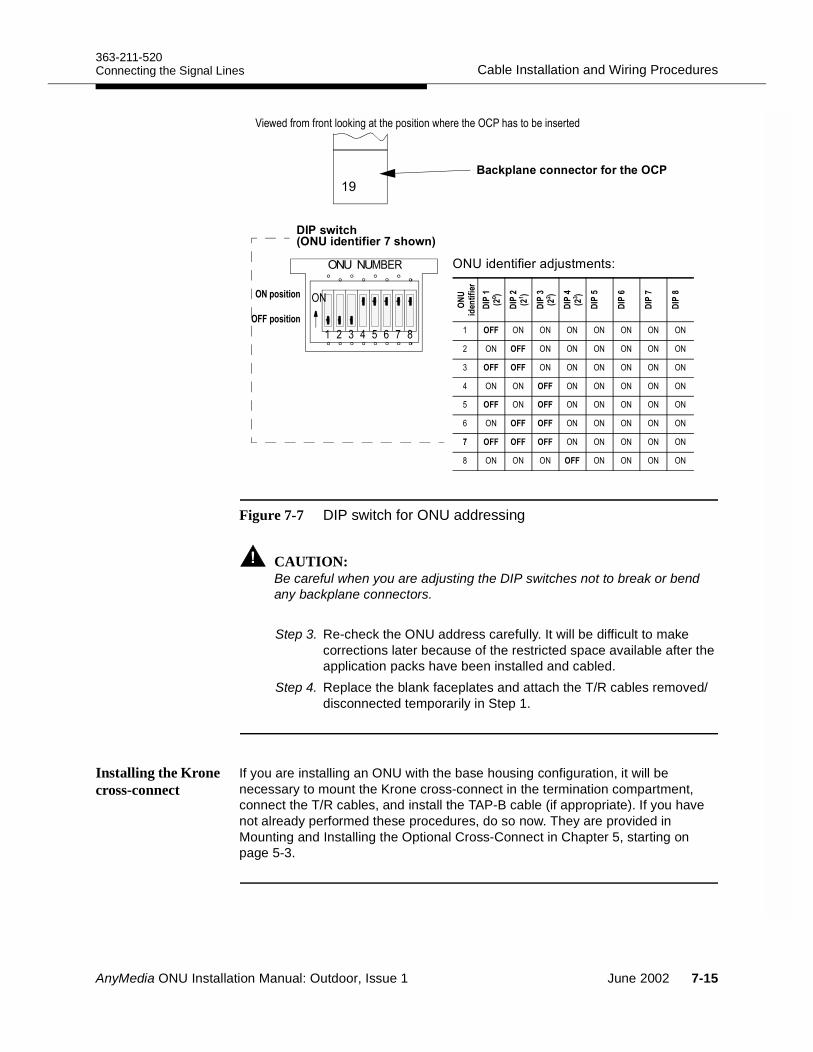
363-211-520Cable Installation and Wiring ProceduresConnecting the Signal Lines
Figure 7-7 DIP switch for ONU addressing
CAUTION:Be careful when you are adjusting the DIP switches not to break or bend any backplane connectors.
Step 3. Re-check the ONU address carefully. It will be difficult to make corrections later because of the restricted space available after the application packs have been installed and cabled.
Step 4. Replace the blank faceplates and attach the T/R cables removed/disconnected temporarily in Step 1.
Installing the Krone cross-connect
If you are installing an ONU with the base housing configuration, it will be necessary to mount the Krone cross-connect in the termination compartment, connect the T/R cables, and install the TAP-B cable (if appropriate). If you have not already performed these procedures, do so now. They are provided in Mounting and Installing the Optional Cross-Connect in Chapter 5, starting on page 5-3.
%&'(
<
)"*+,&('-
! ,
52
1=60 %"#"'%@$,"#A
52 52 52 52 52 52 52
52 52 52 52 52 52 52
52 52 52 52 52 52
52 52 52 52 52 52 52
! 52 52 52 52 52 52
52 52 52 52 52 52
52 52 52 52 52
, 52 52 52 52 52 52 52
7(" " )+#(# #506#&
./ (0
AnyMedia ONU Installation Manual: Outdoor, Issue 1 June 2002 7-15
Cable Installation and Wiring Procedures363-211-520
Connecting the Signal Lines
Marking the TAP100 cable (option)
Use one of the pre-installed T/R cables for the TAP100 cable.
The marking for the TAP100 cable and the connections to the TAP-B cable are only required if the optional test application pack TAP100 is installed. If no TAP100 is installed and the work order does not specify installing the TAP100-to-TAP-B cabling, proceed to “Installing the customer copper cables” on page 7-18 to continue the installation.
Use the following procedure to mark the TAP100 cable:
Step 1. If the slot for the TAP100 plug-in is known mark the appropriate T/R cable on the cross-connect side with the slot position and with “TAP100”.
Step 2. Locate the 4 wires for POTS port numbers 1 and 2 (tip and ring wire of subscribers 1 and 2) and mark them.
NOTE:Only these 2 ports are used by the TAP100 for the test application path B. These 4 terminals must be connected to the TAP-B cable, which runs from the ONU, connector C1 (TAP), to the MDF. Five wires on the TAP-B cable are used for the test application path B; the fifth wire is reserved for future use (seizing). Figure 7-8 illustrates the cross-connect arrangement.
Interconnecting the test application paths (option)
The optional Test Application Pack (TAP100) is the internal test head that performs the measurements required for the drop.
Each AP can switch any of its subscribers to the General Purpose Bus (GPB). The subscriber can be switched either bridged (connection between port and subscriber line is kept) or split (connection between port and subscriber line is opened) to the GPB.
The TAP-B cable is a 13-wire cable of which only 5 wires are used. Four of them are for the circuit pair and the drop pair. The fifth one is for future use. The TAP100 cable is a normal 64-wire T/R cable of which only 4 wires are used (circuit numbers 1 and 2).
Figure 7-8 illustrates the cabling of the test bus, Table 7-2. lists the internal connections between the 4 active wires.
7-16 June 2002 AnyMedia ONU Installation Manual: Outdoor, Issue 1
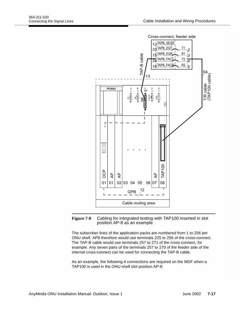
363-211-520Cable Installation and Wiring ProceduresConnecting the Signal Lines
Figure 7-8 Cabling for integrated testing with TAP100 inserted in slot position AP-8 as an example
The subscriber lines of the application packs are numbered from 1 to 256 per ONU shelf. AP8 therefore would use terminals 225 to 256 of the cross-connect. The TAP-B cable would use terminals 257 to 271 of the cross-connect, for example. Any seven pairs of the terminals 257 to 270 of the feeder side of the internal cross-connect can be used for connecting the TAP-B cable.
As an example, the following 4 connections are required on the MDF when a TAP100 is used in the ONU shelf slot position AP-8:
6 6 6
6 6 67 63 6: 6;
66
!"'$#/'"
A43
3 0 4 A
./
92
,
.92
*
,3
4.56
'+(##"(1""%"'%"
3
5( !"
0 66( !"2
863EAF8 8
863EAF. .
863E<08 8
863E<0. .
!
"
#
!!
$#
!"
$%
863EA9GA$!
+8( !"
8
AnyMedia ONU Installation Manual: Outdoor, Issue 1 June 2002 7-17
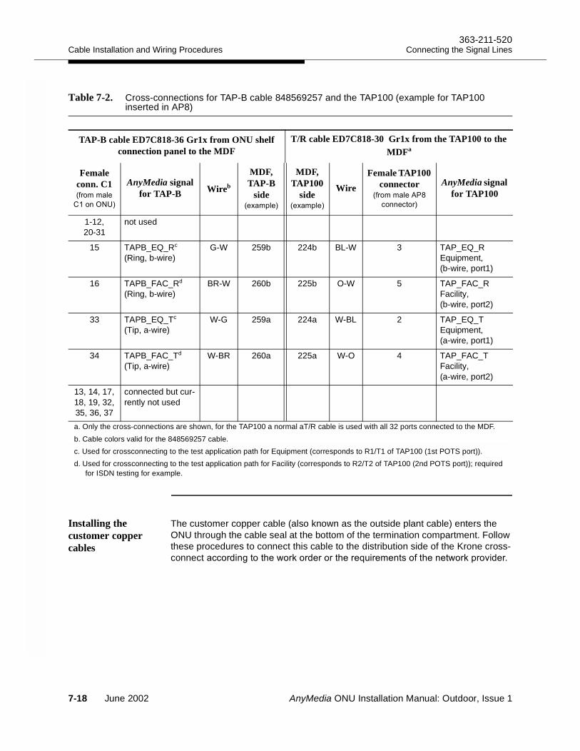
Cable Installation and Wiring Procedures363-211-520
Connecting the Signal Lines
Installing the customer copper cables
The customer copper cable (also known as the outside plant cable) enters the ONU through the cable seal at the bottom of the termination compartment. Follow these procedures to connect this cable to the distribution side of the Krone cross-connect(('%#/)"-'.'%"'')"'"B$'","#)"#"-'.&'=%"'
Table 7-2. Cross-connections for TAP-B cable 848569257 and the TAP100 (example for TAP100 inserted in AP8)
TAP-B cable ED7C818-36 Gr1x from ONU shelf connection panel to the MDF
T/R cable ED7C818-30 Gr1x from the TAP100 to the MDFa
Female conn. C1 0',,!"
#2
AnyMedia signal for TAP-B Wireb
MDF, TAP-B
side 0"9,&!"2
MDF, TAP100
side0"9,&!"2
WireFemale TAP100
connector0',,!" ;
(##"('2
AnyMedia signal for TAP100
1-12, 20-31
not used
15 TAPB_EQ_Rc
(Ring, b-wire)G-W 259b 224b BL-W 3 TAP_EQ_R
Equipment, (b-wire, port1)
16 TAPB_FAC_Rd (Ring, b-wire)
BR-W 260b 225b O-W 5 TAP_FAC_RFacility, (b-wire, port2)
33 TAPB_EQ_Tc (Tip, a-wire)
W-G 259a 224a W-BL 2 TAP_EQ_TEquipment, (a-wire, port1)
34 TAPB_FAC_Td
(Tip, a-wire)W-BR 260a 225a W-O 4 TAP_FAC_T
Facility, (a-wire, port2)
13, 14, 17, 18, 19, 32, 35, 36, 37
connected but cur-rently not used
a. Only the cross-connections are shown, for the TAP100 a normal aT/R cable is used with all 32 ports connected to the MDF.b. Cable colors valid for the 848569257 cable.c. Used for crossconnecting to the test application path for Equipment (corresponds to R1/T1 of TAP100 (1st POTS port)).d. Used for crossconnecting to the test application path for Facility (corresponds to R2/T2 of TAP100 (2nd POTS port)); required
for ISDN testing for example.
7-18 June 2002 AnyMedia ONU Installation Manual: Outdoor, Issue 1
363-211-520Cable Installation and Wiring ProceduresConnecting the Signal Lines
WARNING:Never install telecommunication wiring during a lightning storm or in a wet location.
Use a commercial tent to protect the cables and connectors during inclement weather.
Always equip the distribution side of the internal cross-connect with protector blocks/protector magazines.
Step 1. Verify that the copper cable is sealed and that the cable sheath is correctly grounded.
Step 2. Dress the copper cable so that the T/R pairs reach each module on the distribution side of the cross-connect. Note that the dressing is different for POTS/xDSL and xDSL-only applications: the POTS/xDSL cross-connect is 17.6 in (447 mm) long; the xDSL-only cross-connect is 26 in (663 mm) long.
Step 3. Remove the cable sheath so that the T/R pairs can be easily connected to each module on the distribution side of the cross-connect. Add cable ties as needed to dress the wire bundles, working from the end of the cable sheath to the bottom of the cross-connect mounting bracket.
Step 4. On the work order or the instruction sheet provided by the network provider, identify the connecting sequence and the color coding of the pairs to be connected.
Step 5. Remove the protector magazines on the distribution side, if required.
Step 6. Using the Krone insertion tool (Krone part No. 6417 2 055-01), press the first 10 pairs into the top row of connecting slots of the LSA PLUS disconnection module 1 and trim any access wire.It is recommended that the modules be wired with the a-wire (Tip) terminated on the left position of each connecting pair when viewed from the front.
Comment: If you connect to the LSA 2/10 disconnection modules of the xDSL-only cross-connect, the T/R cabling con-nects to the bottom connection row of the disconnection module (marked with “1” to “10”).
Step 7. Record the copper cable termination assignments in the factory documentation.
Step 8. Repeat Step 6. and Step 7. for each remaining T/R pair. Step 9. Insert all protection magazines removed in Step 5..Step 10.Fold and secure any extra or unterminated wires.
AnyMedia ONU Installation Manual: Outdoor, Issue 1 June 2002 7-19
Cable Installation and Wiring Procedures363-211-520
Connecting the Signal Lines
Installing the cross-connect jumper wires
This section describes the procedure for crosswiring the feeder and distribution side of the Krone cross-connect for ONUs equipped with the ED7C851-56 Gr.1/2 cross-connect kits for POTS/xDSL applications.
NOTE:If your ONU is equipped with the ED7C851-56 Gr.3 cross-connect kit for xDSL-only applications, the top connection row of each LSA 2/10 disconnection module is used for the feeder side, and the bottom connection row is used for the distribution side. There is no crosswiring required, and you may proceed to “Rerouting cross-connections for the ADSL service” on page 7-21.
Materials Required 7
A spool of 0.5 mm (24 AWG), single pair, solid cross-connect wire is recommended for cross-wiring; 0.4 mm wire is not recommended because of its limited strength and electrical fusing characteristic.The single-pair wire must have different colors representing the a-wire (tip) and the b-wire (ring).
Procedure 7
Install the cross-connect jumper wires as follows.
Step 1. From the work order or the instruction sheet provided from the network provider, identify pairs on the feeder side and the distribution side that must be connected.
Step 2. Remove the protector magazines on the distribution side, if required.
Step 3. Unwind about 3 to 6.5 ft (1 to 2 m) of the single-pair wire from the spool. Do not cut the wire from the spool.
Step 4. Using the Krone insertion tool (Krone part No. 6417 2 055-01) press the a- and the b-wire into the appropriate position of the LSA PLUS high-density connection module (gray side) on the feeder side and remove the trimmed wire.
Step 5. Dress the single-pair wire through the wire retainers located on both cross-connect parts to the connecting position on the distribution side. Ensure that about 4 in (100 mm) slack is left near each module.
Step 6. Using the insertion tool, press the a- and the b-wire into the appropriate position on the bottom connection row of the LSA PLUS disconnection module on the distribution side. The insertion tool should cut the wire from the spool.
Step 7. Record the cross-connection in the cable records.Step 8. Repeat Step 1. through Step 7., as required.Step 9. After all jumpers have been connected, wind the unused portion of
the single-pair wire around the spool and tie to ensure it does not uncoil.
7-20 June 2002 AnyMedia ONU Installation Manual: Outdoor, Issue 1
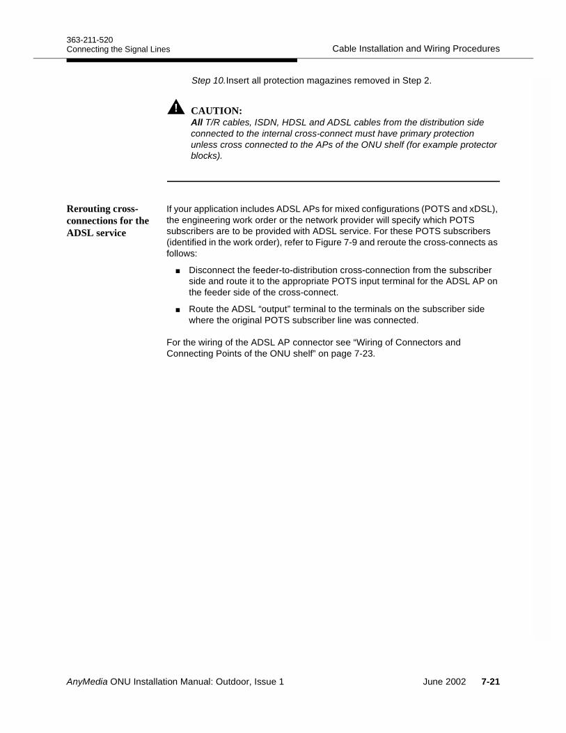
363-211-520Cable Installation and Wiring ProceduresConnecting the Signal Lines
Step 10.Insert all protection magazines removed in Step 2.
CAUTION:All T/R cables, ISDN, HDSL and ADSL cables from the distribution side connected to the internal cross-connect must have primary protection unless cross connected to the APs of the ONU shelf (for example protector blocks).
Rerouting cross-connections for the ADSL service
If your application includes ADSL APs for mixed configurations (POTS and xDSL), the engineering work order or the network provider will specify which POTS subscribers are to be provided with ADSL service. For these POTS subscribers (identified in the work order), refer to Figure 7-9 and reroute the cross-connects as follows:
Disconnect the feeder-to-distribution cross-connection from the subscriber side and route it to the appropriate POTS input terminal for the ADSL AP on the feeder side of the cross-connect.
Route the ADSL “output” terminal to the terminals on the subscriber side where the original POTS subscriber line was connected.
For the wiring of the ADSL AP connector see “Wiring of Connectors and Connecting Points of the ONU shelf” on page 7-23.
AnyMedia ONU Installation Manual: Outdoor, Issue 1 June 2002 7-21
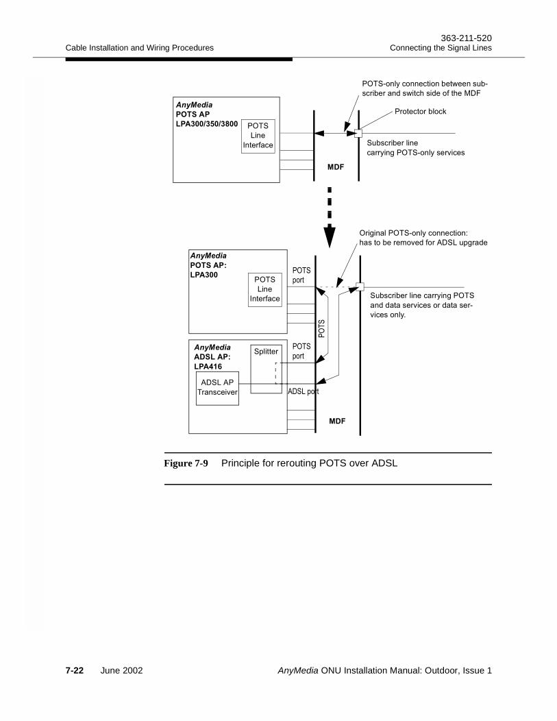
Cable Installation and Wiring Procedures363-211-520
Connecting the Signal Lines
Figure 7-9 Principle for rerouting POTS over ADSL
658
11 1211
34
$ (' "'!#"
(''*#/+#!*"'=("
#"
#"'("
'#("="'
&!"'
$
!
34
'/#!+#!*(##"(#A
) "'",="%' $&/'%"
$ (' "'!#"(''*#/
#%%"'=("'%"'+
=("#!*65
8
4
#"
#"'("
+#!*(##"(# "-""#$ +
(' "'#%-()%")"
$
11
'"(' !(.
658
7-22 June 2002 AnyMedia ONU Installation Manual: Outdoor, Issue 1
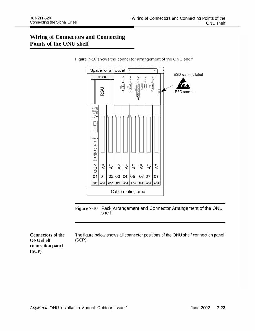
363-211-520 Wiring of Connectors and Connecting Points of theONU shelfConnecting the Signal Lines
Wiring of Connectors and Connecting Points of the ONU shelf 7
Figure 7-10 shows the connector arrangement of the ONU shelf.
Figure 7-10 Pack Arrangement and Connector Arrangement of the ONU shelf
Connectors of the ONU shelf connection panel (SCP)
The figure below shows all connector positions of the ONU shelf connection panel (SCP).
6 6 6
6 6 67 63 6: 6;
!"'$#/'"
A403
3 0 4 A
./
92
,
86
.92
*
,
3
&("''$!"
<:880
/900<
A4
(."
-'##/! "!
AnyMedia ONU Installation Manual: Outdoor, Issue 1 June 2002 7-23
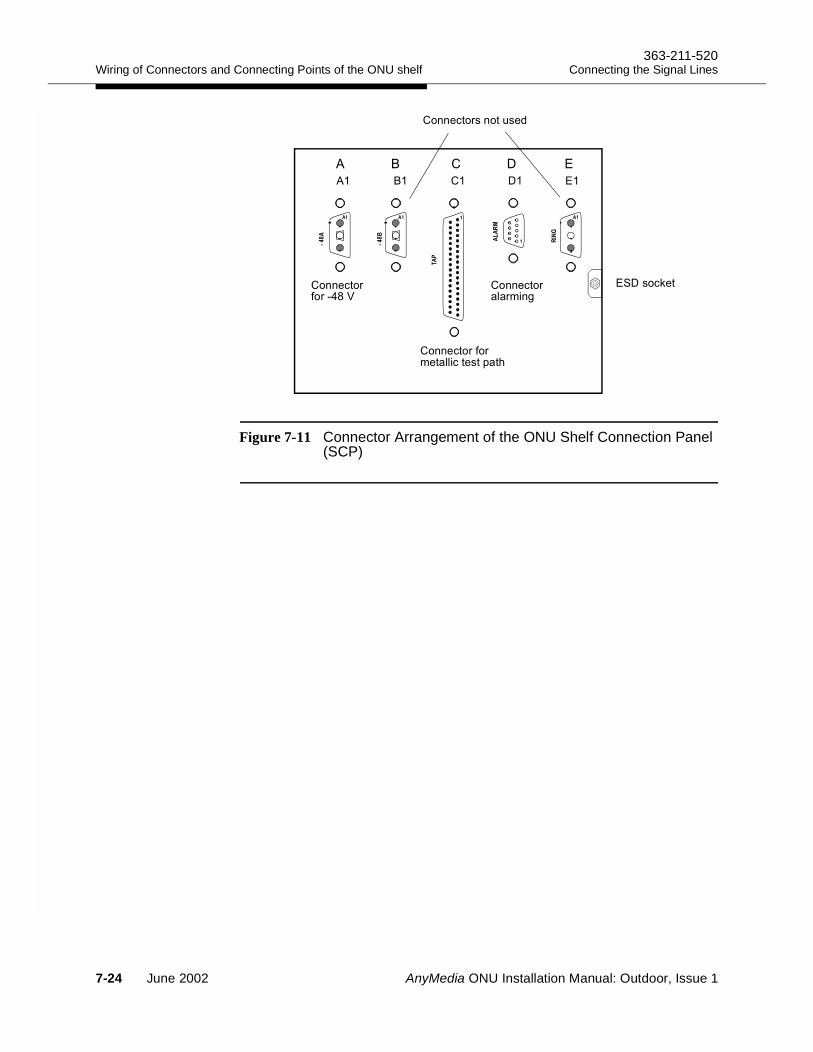
Wiring of Connectors and Connecting Points of the ONU shelf363-211-520
Connecting the Signal Lines
Figure 7-11 Connector Arrangement of the ONUShelf Connection Panel (SCP)
8
8
!
"#
(."
##"('',"!!("&)
##"(''+; ?
##"('!',#/
##"('#$"%
7-24 June 2002 AnyMedia ONU Installation Manual: Outdoor, Issue 1
363-211-520Installing the FiberConnecting the Signal Lines
Installing the Fiber 7
Fiber installation overview
The optical link between the ONU and the remote AnyMedia FAST shelf is through a single fiber connection between the optical controller pack (OCP) in the ONU shelf and the optical application pack (OAP) in the AnyMedia FAST shelf. The term “fiber installation” refers to the process of splicing, routing and connecting that single fiber at both ends. These procedures should be performed after the multifiber that contains that single fiber has been installed and tested.
The fiber installation process includes:
At the remote AnyMedia FAST shelf: Splicing the single fiber with the AnyMedia FAST shelf fiber jumper and routing the fiber from the fiber termination box to the OAP.
At the ONU site: Splicing the single fiber with the pigtail and routing the fiber from the fiber splice organizer to the ONU shelf (see Fiber cabling at the ONU on page 7-27).
Fiber link configuration
In most cases, the fiber routing between the AnyMedia FAST shelf and the ONU is as follows:
From the OAP in the AnyMedia FAST shelf, an SC/SC fiber is routed to a fiber termination box containing two fiber connectors.
From this fiber termination box, a pigtail runs to a fiber splice box where the fiber is spliced to the main multifiber. The multifiber is routed to the remote site where the ONUs are located.
At the remote site, there is also a fiber termination box where the single fibers of the multifiber cable are routed to the ONUs.
Each of these single fibers are spliced to a fiber pigtail which connects to the OCP via an SC-type connector.
At the ONU, a fiber splice organizer is located in the termination compartment.
Optical link interface
The OAP and the OCP are equipped with SC-type fiber connectors.
Two wavelengths are used in the fiber link, one each for transmit and receive. The optical link parameters are listed in Table 7-3.
AnyMedia ONU Installation Manual: Outdoor, Issue 1 June 2002 7-25
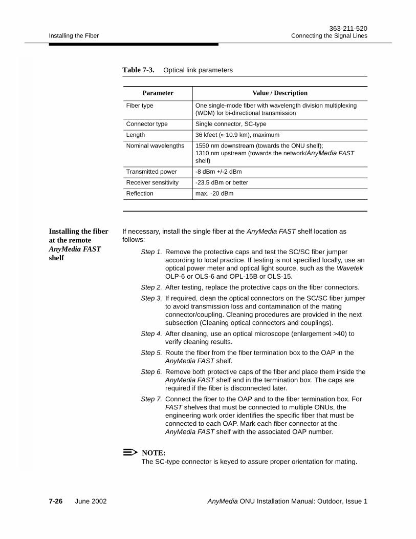
Installing the Fiber363-211-520
Connecting the Signal Lines
Installing the fiber at the remote AnyMedia FAST shelf
If necessary, install the single fiber at the AnyMedia FAST shelf location as follows:
Step 1. Remove the protective caps and test the SC/SC fiber jumper according to local practice. If testing is not specified locally, use an optical power meter and optical light source, such as the Wavetek OLP-6 or OLS-6 and OPL-15B or OLS-15.
Step 2. After testing, replace the protective caps on the fiber connectors. Step 3. If required, clean the optical connectors on the SC/SC fiber jumper
to avoid transmission loss and contamination of the mating connector/coupling. Cleaning procedures are provided in the next subsection (Cleaning optical connectors and couplings).
Step 4. After cleaning, use an optical microscope (enlargement >40) to verify cleaning results.
Step 5. Route the fiber from the fiber termination box to the OAP in the AnyMedia FAST shelf.
Step 6. Remove both protective caps of the fiber and place them inside the AnyMedia FAST shelf and in the termination box. The caps are required if the fiber is disconnected later.
Step 7. Connect the fiber to the OAP and to the fiber termination box. For FAST shelves that must be connected to multiple ONUs, the engineering work order identifies the specific fiber that must be connected to each OAP. Mark each fiber connector at the AnyMedia FAST shelf with the associated OAP number.
NOTE:The SC-type connector is keyed to assure proper orientation for mating.
Table 7-3. Optical link parameters
Parameter Value / Description
Fiber type One single-mode fiber with wavelength division multiplexing (WDM) for bi-directional transmission
Connector type Single connector, SC-type
Length 36 kfeet (≈ 10.9 km), maximum
Nominal wavelengths 1550 nm downstream (towards the ONU shelf);1310 nm upstream (towards the network/ FAST shelf)
Transmitted power -8 dBm +/-2 dBm
Receiver sensitivity -23.5 dBm or better
Reflection max. -20 dBm
7-26 June 2002 AnyMedia ONU Installation Manual: Outdoor, Issue 1
363-211-520Installing the FiberConnecting the Signal Lines
Step 8. Mark the fiber in the termination box. The marking should be specified in the engineering work order. If not, follow local regulations to mark the fibers. If a fiber marking procedures is not specified, it is recommended that you mark each fiber with the AnyMedia FAST shelf/OAP number and mark the leaving fiber (towards the multifiber) with the ONU shelf identifier (ONU addressing), and with the ONU destination location.
NOTE:Be sure that the main multifiber cable has been tested successfully from termination box to termination box using an optical time domain reflectometer (for example: Wavetek MTS5100) to test each fiber.
Cleaning optical connectors and couplings
For outdoor installations, fibers should always be checked for impurities and cleaned, if necessary, before they are connected. When it is necessary to clean any of the optical connectors or couplings at the AnyMedia FAST shelf or ONU sites, proceed as follows:
Step 1. Before cleaning the optical connectors, ensure that the optical source is switched off.
CAUTION:Never look into the end of an exposed fiber or optical connector of a pack while the optical source is switched on. Always observe the laser warning instructions.
Step 2. For connectors, inspect the connector face for impurities (for example lint, dust particles, etc) using a microscope with an magnification factor of 200.
Step 3. For couplers, visually inspect the coupling for residual impurities by holding it to the light (the geometry of the coupling does not allow the coupling to be checked under the microscope).
Step 4. Use isopropanol for cleaning connectors or couplers. Step 5. Let the connector/coupling face air-dry or use purified compressed
air (the isopropanol must evaporate completely).
Fiber cabling at the ONU
Install the fiber cabling at the ONU as follows:
Step 1. Locate the separately delivered fiber pigtail per ONU with an SC-type fiber connector: Use Table 7-4 to identify the fiber pigtail.
AnyMedia ONU Installation Manual: Outdoor, Issue 1 June 2002 7-27
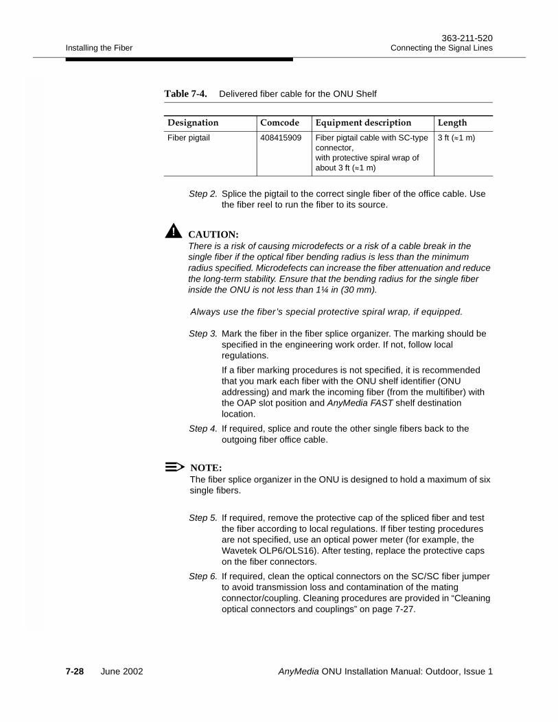
Installing the Fiber363-211-520
Connecting the Signal Lines
Step 2. Splice the pigtail to the correct single fiber of the office cable. Use the fiber reel to run the fiber to its source.
CAUTION:There is a risk of causing microdefects or a risk of a cable break in the single fiber if the optical fiber bending radius is less than the minimum radius specified. Microdefects can increase the fiber attenuation and reduce the long-term stability. Ensure that the bending radius for the single fiber inside the ONU is not less than 1¼ in (30 mm).
Always use the fiber’s special protective spiral wrap, if equipped.
Step 3. Mark the fiber in the fiber splice organizer. The marking should be specified in the engineering work order. If not, follow local regulations. If a fiber marking procedures is not specified, it is recommended that you mark each fiber with the ONU shelf identifier (ONU addressing) and mark the incoming fiber (from the multifiber) with the OAP slot position and AnyMedia FAST shelf destination location.
Step 4. If required, splice and route the other single fibers back to the outgoing fiber office cable.
NOTE:The fiber splice organizer in the ONU is designed to hold a maximum of six single fibers.
Step 5. If required, remove the protective cap of the spliced fiber and test the fiber according to local regulations. If fiber testing procedures are not specified, use an optical power meter (for example, the Wavetek OLP6/OLS16). After testing, replace the protective caps on the fiber connectors.
Step 6. If required, clean the optical connectors on the SC/SC fiber jumper to avoid transmission loss and contamination of the mating connector/coupling. Cleaning procedures are provided in “Cleaning optical connectors and couplings” on page 7-27.
Table 7-4. Delivered fiber cable for the ONU Shelf
Fiber pigtail 408415909 Fiber pigtail cable with SC-type connector, with protective spiral wrap of about 3 ft (≈1 m)
3 ft (≈1 m)
7-28 June 2002 AnyMedia ONU Installation Manual: Outdoor, Issue 1
363-211-520Installing the FiberConnecting the Signal Lines
Step 7. Insert the fiber pigtail through the opening behind the organizer to the electronic compartment of the ONU.
Step 8. If you haven’t already done so, open the door of the electronic compartment of the ONU and latch the door in position.
Step 9. Locate the fiber pigtail just inserted on the left side and route the fiber with the protective spiral wrap side to the OCP position of the ONU shelf.
Step 10.Arrange the fiber with the previously installed T/R cables on the left side of the ONU housing and dress them horizontally. Add cable ties as needed.
Step 11.Mark the fiber connector with the ONU shelf identifier (ONU addressing) if more than one ONU is located on the site.
Step 12.If no OCP is inserted, replace the protective cap on the fiber connector. Put the fiber connector between the left ONU housing side and the ONU shelf where the fiber will be protected.
Step 13.If the OCP is in place, remove the protective cap from the SC-type fiber connector of the OCP and place it inside the ONU shelf.
Step 14.Orient the mating fiber connector so that the fiber routes upward toward the OCP. For the cabling arrangement inside the ONU shelf see Figure 7-2, Figure 7-3, and Figure 7-4.
Step 15.Affix the fiber with care to the grounding bracket fingers of the ONU shelf directly below the OCP. Do not over-tighten the tie.
AnyMedia ONU Installation Manual: Outdoor, Issue 1 June 2002 7-29

Installing the Fiber363-211-520
Connecting the Signal Lines
7-30 June 2002 AnyMedia ONU Installation Manual: Outdoor, Issue 1
AnyMedia ONU Installation Manual: Outdoor, Issue 1
Connecting AC Power 8Overview 8
This chapter describes the requirements and procedures for connecting the ONU to the local electric utility.
Contents
Page
AC Power Supply Service 8-2Utility power arrangements 8-2
AC cable routing 8-3
Grounding the ground wire 8-3
Connecting to the AC Utility 8-4
Precautions 8-4
Checking the AC power supply 8-4
Connecting the AC power supply 8-4
Connecting to the auxiliary power generator 8-7
June 2002 8-1
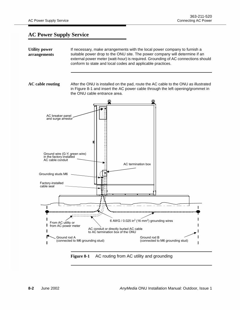
AC Power Supply Service363-211-520
Connecting AC Power
AC Power Supply Service 8
Utility power arrangements
If necessary, make arrangements with the local power company to furnish a suitable power drop to the ONU site. The power company will determine if an external power meter (watt-hour) is required. Grounding of AC connections should conform to state and local codes and applicable practices.
AC cable routing After the ONU is installed on the pad, route the AC cable to the ONU as illustrated in Figure 8-1 and insert the AC power cable through the left opening/grommet in the ONU cable entrance area.
Figure 8-1 AC routing from AC utility and grounding
&4"
, !, 8% $ 1 &
, 9
/1
& :
, &! 9 $
, (! 9 $
&7,- !$ /&1&"
& 1&& :)*+
8-2 June 2002 AnyMedia ONU Installation Manual: Outdoor, Issue 1
363-211-520AC Power Supply ServiceConnecting AC Power
Grounding the ground wire
Connect the ground wire to the M6 ONU housing grounding stud.
When connecting to TN-C systems, an additional N-pole to ground pole connection is required inside the ONU between the ONU AC distribution .
AnyMedia ONU Installation Manual: Outdoor, Issue 1 June 2002 8-3
Connecting to the AC Utility363-211-520
Connecting AC Power
Connecting to the AC Utility 8
Precautions Ensure that the ground green wire of the AC cable is connected to the central approved grounding point according to local regulations.
NOTE:Check the ONU grounding connections before you connect the AC power supply. Procedures for verifying the grounding connections are provided in Checking the Ground Connections on page 6-18.
WARNING:Hazardous voltages are present on the AC cable. Follow all safety warnings and practices when installing and servicing this equipment.
Checking the AC power supply
Before connecting the ONU to the AC power supply for the first time check the following items:
Step 1. Measure the voltage on the utility power supply and verify that it is in the range as stated in the engineering work order.
Step 2. Verify that the utility power supply is switched to “OFF” and cannot be turned on accidently. Mark the OFF state if required. Follow local regulations for securing and marking the power supply.
Step 3. Verify that the cable is de-energized. If required, short the deactivated power supply to ground. Follow local regulations.
Step 4. Verify that the AC circuit breaker of the ONU is switched to OFF.Step 5. If you have not already done so, remove the cover of the AC
termination box in the termination compartment.Step 6. Verify that the AC power supply cable from the ONU AC termination
block is routed to the utility side. Do not connect.
Connecting the AC power supply
If the AC cable is not connected, connect the AC cable as follows:
NOTE:The diameter and the length of AC cable used for connecting to the AC utility must be consistent with the cut-off conditions of the primary fuse/breaker.
Step 1. Strip the AC power supply cable long enough so that the cable can be connected securely on the AC utility side. Strip each of the three
8-4 June 2002 AnyMedia ONU Installation Manual: Outdoor, Issue 1
363-211-520Connecting to the AC UtilityConnecting AC Power
wires to a length according to the terminals used in the AC utility side.
Step 2. Insert the ground wire into the ground terminal and screw tight or connect/fix. Connect the L1 and L2/N wire as prescribed by the local power company.
Step 3. Cut the AC cable so that it reaches the termination clamp of the AC termination box.
Step 4. Strip the wires so that they can be connected to the terminals of the termination box.
Step 5. Connect the wires as shown on the decal of the termination box.
NOTE:The terminals inside the AC termination box are designed for solid wires, 6 to18 AWG.
Step 6. Insert the brown and the blue wire into the correct terminals for L1 and L2/N and screw tight or connect/fix. Follow local regulations for these connections.
Step 7. Check that the wires are dressed.Step 8. Replace the cover of the AC termination box in the ONU
termination compartment.Step 9. If you previously shorted the deactivated power supply on the utility
side, remove the short. Follow local regulations.Step 10.Verify that the AC breaker of the ONU is switched to OFF and that
all covers of the AC termination box and the AC breaker panel are mounted. Bear in mind that the AC cable is energized. If required, mark on the AC breaker panel that the ONU is energized.
Step 11.If you are continuing with the ONU installation, switch the AC utility to “ON.”
Step 12.It is recommended that the connection to the AC utility be documented. Also a label should be attached inside the ONU indicating the type of AC distribution, the installation date and the installation point to which the AC is connected. If the AC utility connection point is not freely accessible by service personnel, the telephone number of the local power company should be included in the documentation.
Step 13.Verify that all cable seals, grommets and the other gaps at the bottom of the cable entrance in the termination compartment are still properly sealed, see Sealing and Caulking the ONU Cables on page 6-19.
Step 14.Latch the termination compartment door in position.
AnyMedia ONU Installation Manual: Outdoor, Issue 1 June 2002 8-5
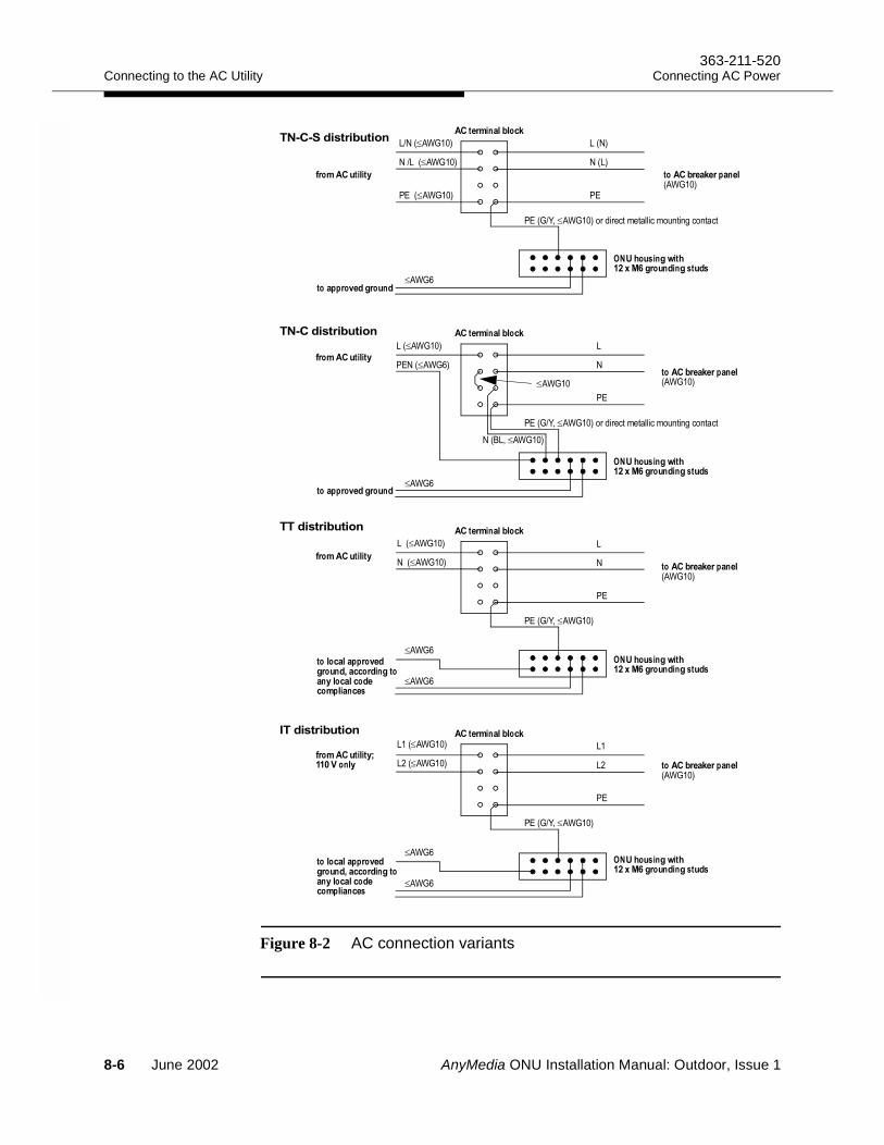
Connecting to the AC Utility363-211-520
Connecting AC Power
Figure 8-2 AC connection variants
≤
≤
≤
≤
≤
≤
≤
≤
≤
≤
≤
≤
≤
≤
≤
≤
≤
≤
!!"#
≤
≤
!$%&'
!$%&'
!$%&'
!$%&'
≤
8-6 June 2002 AnyMedia ONU Installation Manual: Outdoor, Issue 1
363-211-520Connecting to the AC UtilityConnecting AC Power
Connecting to the auxiliary power generator
An external power generator can be connected to protect against permanent loss of AC power. A special raw ended power cord with an IEC 60320 plug is provided (Comcode 848506820) for this purpose. This plug must be inserted into the IEC 60320 inlet of the ONU instead of the power cord coming from the AC breaker panel.
AnyMedia ONU Installation Manual: Outdoor, Issue 1 June 2002 8-7

Connecting to the AC Utility363-211-520
Connecting AC Power
8-8 June 2002 AnyMedia ONU Installation Manual: Outdoor, Issue 1
AnyMedia ONU Installation Manual: Outdoor, Issue 1
Installing the Batteries 9Overview 9
This section provides the procedures for unpacking, inspecting, and mounting the batteries in the ONU battery compartment.
NOTE:If you are familiar with the battery installation and with the storage/charging procedures and warranty considerations, you can skip to page 9-9 and begin by unpacking the batteries.
Contents
Page
Battery Option 9-3Ordering Batteries 9-3Battery description 9-3
Battery Safety 9-5General safety precautions 9-5Gas discharge 9-5Sparks 9-6Short circuits 9-6Conductive surface 9-6Contact with electrolyte 9-6Acid spills 9-6
June 2002 9-1
Overview363-211-520
Installing the Batteries
Battery Handling and Preparation 9-7Required tools, supplies and equipment 9-7Battery handling 9-7Shipping and storing IR-40EC batteries 9-8Unpacking and completeness check 9-9
Battery inspection and initial charging 9-10
Installing the Batteries 9-13
Battery arrangement 9-13
Installation procedure 9-14
Page
9-2 June 2002 AnyMedia ONU Installation Manual: Outdoor, Issue 1
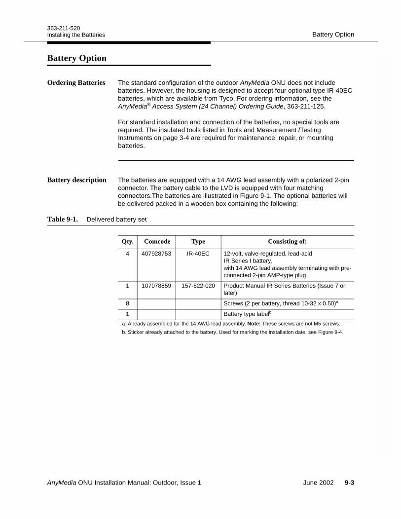
363-211-520Battery OptionInstalling the Batteries
Battery Option 9
Ordering Batteries The standard configuration of the outdoor AnyMedia ONU does not include batteries. However, the housing is designed to accept four optional type IR-40EC batteries, which are available from Tyco. For ordering information, see the AnyMedia® Access System (24 Channel) Ordering Guide, 363-211-125.
For standard installation and connection of the batteries, no special tools are required. The insulated tools listed in Tools and Measurement /Testing Instruments on page 3-4 are required for maintenance, repair, or mounting batteries.
Battery description The batteries are equipped with a 14 AWG lead assembly with a polarized 2-pin connector. The battery cable to the LVD is equipped with four matching connectors.The batteries are illustrated in Figure 9-1. The optional batteries will be delivered packed in a wooden box containing the following:
Table 9-1. Delivered battery set
Qty. Comcode Type Consisting of:
4 407928753 IR-40EC 12-volt, valve-regulated, lead-acid IR Series I battery, with 14 AWG lead assembly terminating with pre-connected 2-pin AMP-type plug
1 107078859 157-622-020 Product Manual IR Series Batteries (Issue 7 or later)
8 Screws (2 per battery, thread 10-32 x 0.50)a
1 Battery type labelb a. Already assembled for the 14 AWG lead assembly. Note: These screws are not M5 screws.b. Sticker already attached to the battery. Used for marking the installation date, see Figure 9-4.
AnyMedia ONU Installation Manual: Outdoor, Issue 1 June 2002 9-3
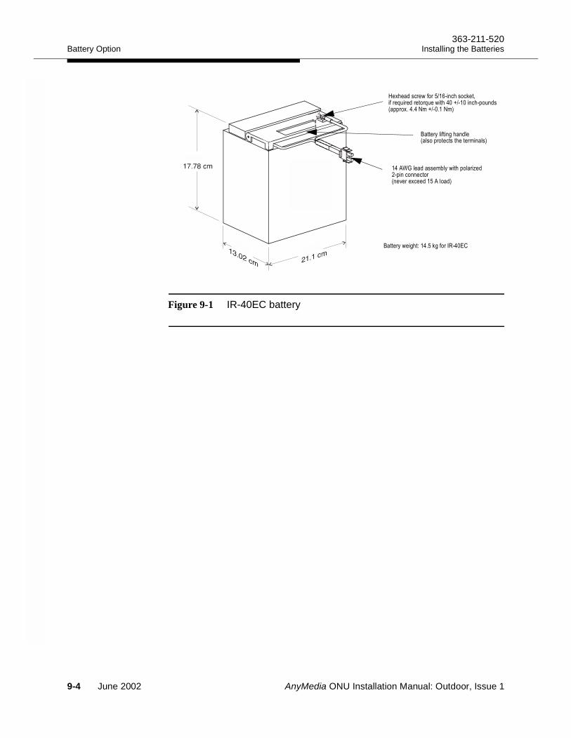
Battery Option363-211-520
Installing the Batteries
Figure 9-1 IR-40EC battery
3 '(+#>!)+" 9.A0
1 # (" !#)%" ? ?(#H# 2H2
;*&'(# - $ !
3 '"+# #
9-4 June 2002 AnyMedia ONU Installation Manual: Outdoor, Issue 1
363-211-520Battery SafetyInstalling the Batteries
Battery Safety 9
General safety precautions
For safe battery handling, always observe the following basic precautions:
Use only properly insulated tools and test equipment.
Remove all metallic objects (key chains, glasses, rings, watches, or any other jewelry).
Wear safety glasses, acid-resistant gloves, rubber overshoes and apron.
Test circuits before touching.
Lock out and tag any circuit breakers or fuses whenever possible to prevent accidental turn-on.
Be aware of potential hazards before servicing equipment.
Do not short the battery.
Identify exposed hazardous electrical potentials on connectors, wiring, etc. (Note the condition of these circuits, especially any wiring).
Take care when removing or replacing any covers or brackets. Avoid contacting terminals.
Always verify the polarity before connecting cables to the batteries.
Use a damp soft cloth for cleaning batteries. Do not use solvents, paraffin, abrasive or proprietary cleaning fluids.
While unpacking and/or installing the batteries:
Never place metal objects (including tools) on top of a battery.
Never short out the battery terminals.
Never use an open flame near batteries.
Never stack batteries (in or out of their shipping cardboard boxes).
Never transport or move batteries so that their weight is supported by the terminal connections.
Never charge batteries that are visibly damaged or frozen (typically at temperatures below -40°C if the battery is fully charged).
Gas discharge All lead-acid batteries generate hydrogen gas, even under open circuit conditions. If not permitted to escape, this gas can build up to explosive concentrations. An explosion could occur when sparks are created near the battery string. Do not place batteries in a sealed enclosure. Freshly charged batteries are especially prone to discharging explosive gases for about 24 hours after charging.
AnyMedia ONU Installation Manual: Outdoor, Issue 1 June 2002 9-5
Battery Safety363-211-520
Installing the Batteries
Sparks To avoid sparks, ensure that batteries are not charging or discharging before loosening or removing battery connections. Sparks can trigger an explosion and short circuit other battery modules, causing a fire. The GMT-type fuse in the LVD can produce sparks during interruption or clearing of a fault on a high energy circuit. Any mechanical power switches and also static electricity are sources of spark gaps.
Short circuits Be very careful when taking voltage readings to prevent accidental grounding or shorting of leads during measurements. Connections at the meter must be secure and free of any possibility of touching or becoming grounded. Never remove connections at the meter end without first disconnecting the test leads from the battery. Remove test lead connections at the battery immediately after each reading is taken.
WARNING:Exercise extreme care to avoid any short circuit across the battery terminals. Even a single battery poses a potentially high energy hazard if shorted. Shorting a battery may result in explosion of the battery, injury to the installer, and damage to equipment. A tool or other metallic object causing the short may be thrown or vaporized due to the battery energy.
Conductive surface If the battery is to be installed on an electrically conductive surface, a non-conductive mat or surface should be placed between the battery and the conductive surface.
Contact with electrolyte
In the event of electrolyte contact with the skin, remove the electrolyte immediately by rinsing the affected area with large amounts of plain tap water. In the event of electrolyte in the eye, pour water into the inner corner of the eye and allow at least one liter of water to run over the eye and under the eyelid. Eye injuries should be treated by a physician immediately.
Acid spills If large acid spillage occurs, use agricultural or industrial lime instead of soda for neutralization before cleanup. If lime is not available, you may use baking soda. Wear eye protection devices and rubber gloves when using lime on electrolyte spills. Sprinkle the lime on the spillage; allow it to absorb the electrolyte, and then sweep it up and dispose of it in the proper manner. Wash hands and face thoroughly after cleanup.
9-6 June 2002 AnyMedia ONU Installation Manual: Outdoor, Issue 1
363-211-520Battery Handling and PreparationInstalling the Batteries
Battery Handling and Preparation 9
The following describes how to install the Tyco IR-40EC battery string. It also provides test procedures for verifying the integrity of the installation.
NOTE:Batteries should be installed after all cables have been installed.
The regulations for storage, handling, external charging, and maintenance are different for each battery manufacturer. For IR-40EC batteries, follow the regulations given in the Product Manual for IR Series Batteries.
Required tools, supplies and equipment
You will need the following tools and materials to install and test the battery string:
Splash-proof safety goggles, acid-resistant gloves, rubber overshoes, and apron
Cleaning cloth
Lime and/or soda (sodium bicarbonate)
Insulated socket driver or nut driver set (1/4-inch through 3/4-inch sockets) and torque wrench (0 to 60 in-lbs, 6 Nm) for maintenance/replacement only
Sandpaper or abrasive cloth for cleaning the battery compartment only
DMM (Digital Multimeter), for example, Tek DM254 or Fluke 8060A or equivalent. The accuracy of an equivalent meter should be 0.05 percent on the DC scale.
Current converter or current probe 1:10 for multimeter used for up to 20 A
Thermometers for measuring the ambient temperature and the battery temperature (contact type)
Waterproof fine line marker for marking batteries and the connectors, also required to write the installation date onto the batteries.
A Class C fire extinguisher (kept within reach)
Battery handling Before handling batteries, read and understand the sections of the Product Manual IR Series Batteries that apply to IR-40EC batteries.
When removing containers from the shipping van, place them on a dolly truck in their horizontal shipping positions. Verify that the containers have not been damaged. It is important that all containers be handled with care and not dropped.
The weight of the packed batteries in their shipping container is about 132 lbs (60 kg) for four batteries of type IR-40EC. Do not apply silicone grease to IR-
AnyMedia ONU Installation Manual: Outdoor, Issue 1 June 2002 9-7
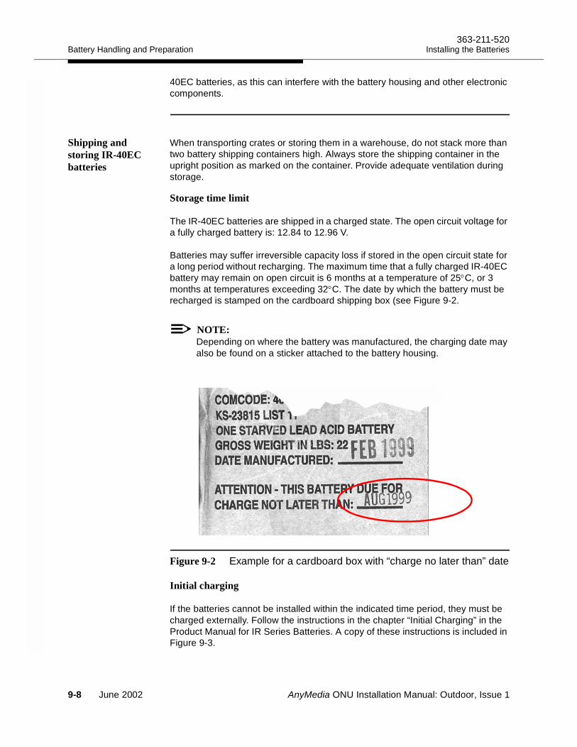
Battery Handling and Preparation363-211-520
Installing the Batteries
40EC batteries, as this can interfere with the battery housing and other electronic components.
Shipping and storing IR-40EC batteries
When transporting crates or storing them in a warehouse, do not stack more than two battery shipping containers high. Always store the shipping container in the upright position as marked on the container. Provide adequate ventilation during storage.
Storage time limit 9
The IR-40EC batteries are shipped in a charged state. The open circuit voltage for a fully charged battery is: 12.84 to 12.96 V.
Batteries may suffer irreversible capacity loss if stored in the open circuit state for a long period without recharging. The maximum time that a fully charged IR-40EC battery may remain on open circuit is 6 months at a temperature of 25°C, or 3 months at temperatures exceeding 32°C. The date by which the battery must be recharged is stamped on the cardboard shipping box (see Figure 9-2.
NOTE:Depending on where the battery was manufactured, the charging date may also be found on a sticker attached to the battery housing.
Figure 9-2 Example for a cardboard box with “charge no later than” date
Initial charging 9
If the batteries cannot be installed within the indicated time period, they must be charged externally. Follow the instructions in the chapter “Initial Charging” in the Product Manual for IR Series Batteries. A copy of these instructions is included in Figure 9-3.
9-8 June 2002 AnyMedia ONU Installation Manual: Outdoor, Issue 1
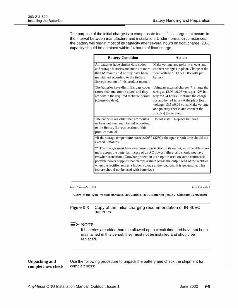
363-211-520Battery Handling and PreparationInstalling the Batteries
The purpose of the initial charge is to compensate for self discharge that occurs in the interval between manufacture and installation. Under normal circumstances, the battery will regain most of its capacity after several hours on float charge; 90% capacity should be obtained within 24 hours of float charge.
________________________________________________________________
Issue 7 November 1998 Installation 6 - 7
COPY of the Tyco Product Manual IR-30EC and IR-40EC Batteries (Issue 7, Comcode 107078859)
Figure 9-3 Copy of the initial charging recommendation of IR-40EC batteries
NOTE:If batteries are older than the allowed open circuit time and have not been maintained in this period, they must not be installed and should be replaced.
Unpacking and completeness check
Use the following procedure to unpack the battery and check the shipment for completeness:
Battery Condition Action
All batteries have similar date codes and storage histories and none are more than 6* months old or they have been maintained according to the Battery Storage section of this product manual.
Make voltage and polarity checks and connect string(s) to plant. Charge at the float voltage of 13.5 ±0.06 volts per battery
The batteries have dissimilar date codes (more than one month apart) and they are within the required recharge period (charge-by date).
Using an external charger**, charge the string at 13.98 ±0.06 volts per 12V bat-tery for 24 hours. Continue the charge for another 24 hours at the plant float voltage: 13.5 ±0.06 volts. Make voltage and polarity checks and connect the string(s) to the plant
The batteries are older than 6* months or have not been maintained according to the Battery Storage section of this product manual.
Do not install. Replace batteries.
*If the storage temperature exceeds 90°F (32°C), the open circuit time should not exceed 3 months.
** The charger must have overcurrent protection in its output, must be able to re-main across the batteries in case of an AC power failure, and should not have crowbar protection. (Crowbar protection is an option used on some commercial portable power supplies that clamps a short across the output lead of the rectifier when the rectifier senses a higher voltage at the load than it is generating. This feature should not be used with batteries.)
AnyMedia ONU Installation Manual: Outdoor, Issue 1 June 2002 9-9
Battery Handling and Preparation363-211-520
Installing the Batteries
Step 1. Move the pallet with the wooden box containing the batteries and the battery accessories in close proximity to the ONU.
NOTE:Use appropriate material handling equipment to move the battery pallet. An IR-40EC battery weighs about ! (15 kg).
Step 2. Using slip joint pliers, remove all the staples/nails from the wooden battery shipping container and dispose of them properly.
Step 3. Locate the loose parts delivered with the batteries including the Product Manual IR Series Batteries (Issue 7 or later, Comcode 107078859).
NOTE:If there are any problems with the delivered equipment or if any items are missing, refer to the job specification or equipment order for the name and telephone number of the local manager to contact and to rectify the problem.
Step 4. Locate the Installation and Maintenance Record in the Product Manual IR Series Batteries and reproduce it or use the copies in Appendix A Installation and Maintenance RecordUse the installation and maintenance record to record the parameters measured during installation and at quarterly maintenance procedures. The completed forms will be required for warranty validation.
Battery inspection and initial charging
Use the following procedure to inspect the battery and prepare it for installation:
Step 1. The packing list includes the order number. Record this order number in the Installation and Maintenance Record.
Step 2. Take out the first battery and place the battery on a level surface. Step 3. Inspect the battery for shipping damage/obvious damage and for
any sign of acid spillage.Step 4. Check the battery for fractured housings. Batteries with fractured
housings are defective and must not be used. Return damaged batteries to the manufacturer in their original packing.
Step 5. Mark the first battery, the 2-pin connector and the cardboard box with the numeral 1. This number is required for the installation record.
Step 6. Verify that the battery has not reached the open circuit time limit (see Figure 9-2).
Step 7. Follow the instructions for Initial Charging in the Product Manual IR Series Batteries (see Figure 9-3). Observe the battery
9-10 June 2002 AnyMedia ONU Installation Manual: Outdoor, Issue 1
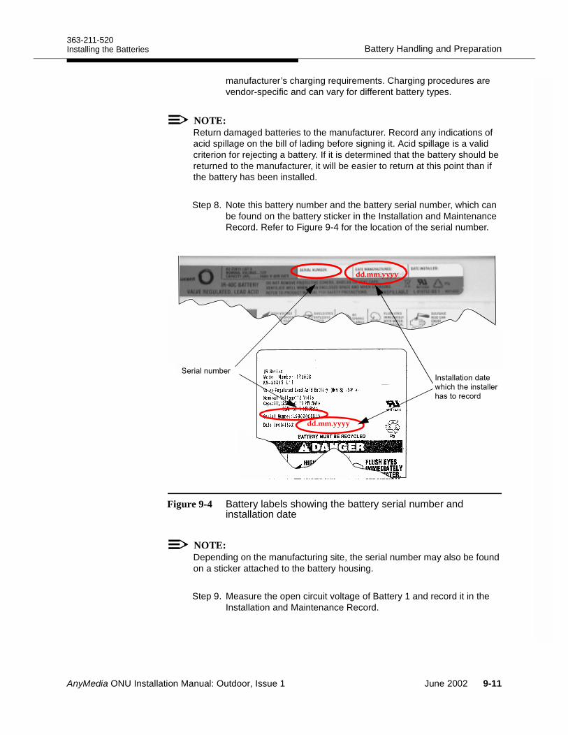
363-211-520Battery Handling and PreparationInstalling the Batteries
manufacturer’s charging requirements. Charging procedures are vendor-specific and can vary for different battery types.
NOTE:Return damaged batteries to the manufacturer. Record any indications of acid spillage on the bill of lading before signing it. Acid spillage is a valid criterion for rejecting a battery. If it is determined that the battery should be returned to the manufacturer, it will be easier to return at this point than if the battery has been installed.
Step 8. Note this battery number and the battery serial number, which can be found on the battery sticker in the Installation and Maintenance Record. Refer to Figure 9-4 for the location of the serial number.
Figure 9-4 Battery labels showing the battery serial number and installation date
NOTE:Depending on the manufacturing site, the serial number may also be found on a sticker attached to the battery housing.
Step 9. Measure the open circuit voltage of Battery 1 and record it in the Installation and Maintenance Record.
#!!#%"-)())"#!!"'
)'"('%
"'!#$, "'
AnyMedia ONU Installation Manual: Outdoor, Issue 1 June 2002 9-11
Battery Handling and Preparation363-211-520
Installing the Batteries
NOTE:Only in a running system may the IR-40EC battery be discharged to 10.5 V.
NOTE:If the battery voltage is 12.84 V or below, the complete battery string must be charged by the internal power rectifier unit immediately after mechanical installation. Otherwise, the batteries must be charged externally.
NOTE:If the measured battery voltage is below 12 V the battery should be considered defective (cell short) and may not be installed.
Step 10.Note the installation date on the sticker of each battery and also in the Installation and Maintenance Record in the field Date Installed.
Step 11.Repeat Steps 4 to 10 for the other 3 batteries, marking them sequentially 2 though 4 in Step 5.
9-12 June 2002 AnyMedia ONU Installation Manual: Outdoor, Issue 1
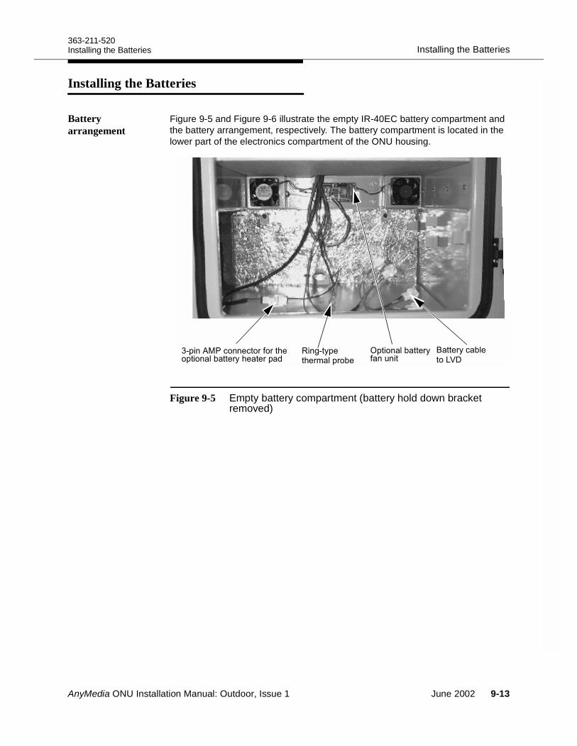
363-211-520Installing the BatteriesInstalling the Batteries
Installing the Batteries 9
Battery arrangement
Figure 9-5 and Figure 9-6 illustrate the empty IR-40EC battery compartment and the battery arrangement, respectively. The battery compartment is located in the lower part of the electronics compartment of the ONU housing.
Figure 9-5 Empty battery compartment (battery hold down bracket removed)
8"'*( !"#/+*&"+&# (##"('')"&#! "'*)""'&%
&#! "'*#$#)"',!&' " ?
AnyMedia ONU Installation Manual: Outdoor, Issue 1 June 2002 9-13
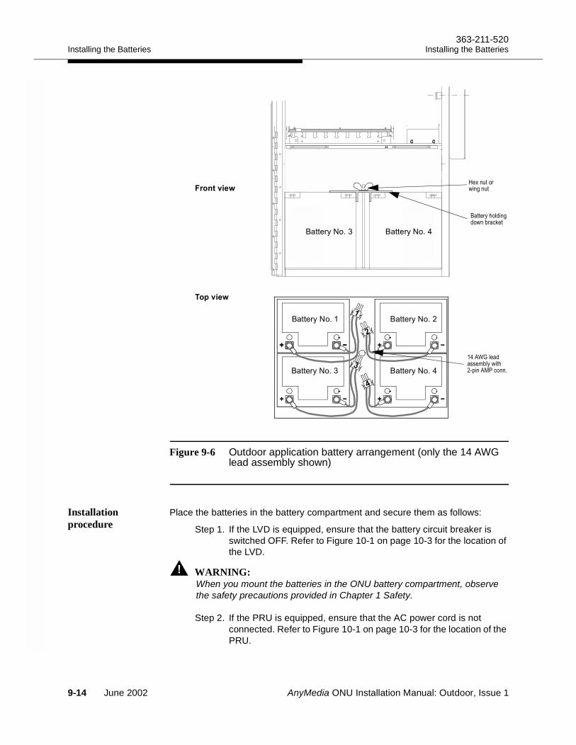
Installing the Batteries363-211-520
Installing the Batteries
Figure 9-6 Outdoor application battery arrangement (only the 14 AWG lead assembly shown)
Installation procedure
Place the batteries in the battery compartment and secure them as follows:
Step 1. If the LVD is equipped, ensure that the battery circuit breaker is switched OFF. Refer to Figure 10-1 on page 10-3 for the location of the LVD.
WARNING:When you mount the batteries in the ONU battery compartment, observe the safety precautions provided in Chapter 1 Safety.
Step 2. If the PRU is equipped, ensure that the AC power cord is not connected. Refer to Figure 10-1 on page 10-3 for the location of the PRU.
8"'* 8"'*
8"'*8"'*
3 '#+
1 (+
8"'* 8"'*
45'
5'
(& )
;*&'(#/6
9-14 June 2002 AnyMedia ONU Installation Manual: Outdoor, Issue 1
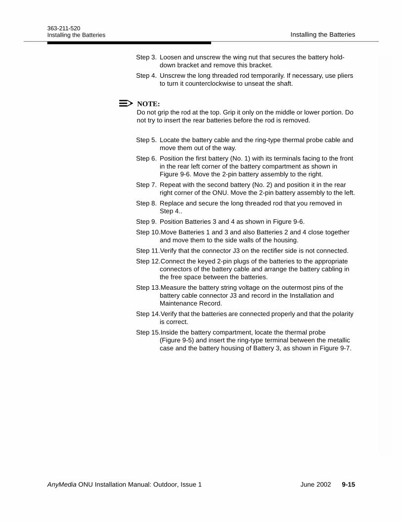
363-211-520Installing the BatteriesInstalling the Batteries
Step 3. Loosen and unscrew the wing nut that secures the battery hold- down bracket and remove this bracket.
Step 4. Unscrew the long threaded rod temporarily. If necessary, use pliers to turn it counterclockwise to unseat the shaft.
NOTE:Do not grip the rod at the top. Grip it only on the middle or lower portion. Do not try to insert the rear batteries before the rod is removed.
Step 5. Locate the battery cable and the ring-type thermal probe cable and move them out of the way.
Step 6. Position the first battery (No. 1) with its terminals facing to the front in the rear left corner of the battery compartment as shown in Figure 9-6. Move the 2-pin battery assembly to the right.
Step 7. Repeat with the second battery (No. 2) and position it in the rear right corner of the ONU. Move the 2-pin battery assembly to the left.
Step 8. Replace and secure the long threaded rod that you removed in Step 4..
Step 9. Position Batteries 3 and 4 as shown in Figure 9-6.Step 10.Move Batteries 1 and 3 and also Batteries 2 and 4 close together
and move them to the side walls of the housing.Step 11.Verify that the connector J3 on the rectifier side is not connected. Step 12.Connect the keyed 2-pin plugs of the batteries to the appropriate
connectors of the battery cable and arrange the battery cabling in the free space between the batteries.
Step 13.Measure the battery string voltage on the outermost pins of the battery cable connector J3 and record in the Installation and Maintenance Record.
Step 14.Verify that the batteries are connected properly and that the polarity is correct.
Step 15.Inside the battery compartment, locate the thermal probe (Figure 9-5) and insert the ring-type terminal between the metallic case and the battery housing of Battery 3, as shown in Figure 9-7.
AnyMedia ONU Installation Manual: Outdoor, Issue 1 June 2002 9-15
Installing the Batteries363-211-520
Installing the Batteries
Figure 9-7 Position of the ring-type thermal probe
Step 16.Locate the battery hold-down bracket. Mount and tighten the wing nut as shown in Figure 9-8.
Figure 9-8 Mounted batteries (Batteries 1 and 2 already inserted; Batteries No. 4 and No. 5 to be inserted)
8"'*)"',!&' "#"'"% "-""#,"!!(("#%&!( "'*)$#/ "'*
! "
!
!#$%
!#$&
'
()*)
9-16 June 2002 AnyMedia ONU Installation Manual: Outdoor, Issue 1
AnyMedia ONU Installation Manual: Outdoor, Issue 1
System Power Up 10Overview 10
This chapter provides the procedures for installing power-related modules, applying AC power and activating the batteries.
Page
Installing the Power and Ringing Modules 10-3 Installing the PRU 10-5
PRU features 10-5PRU installation procedure 10-5
Installing the LVD 10-7LVD functions and features 10-7LVD installation procedures 10-7
Installing the Optional RGU 10-9RGU functions 10-9RGU installation procedure 10-9
Applying AC Power 10-11 Checking the Rectifier and Batteries 10-13
PRU voltage range 10-13Verifying the batteries and rectifier 10-14
June 2002 10-1
Overview363-211-520
System Power Up
Connecting and Charging the Batteries 10-16Battery voltage balance 10-16Battery specifications 10-16Procedure for connecting and charging the batteries 10-17
Page
10-2 June 2002 AnyMedia ONU Installation Manual: Outdoor, Issue 1
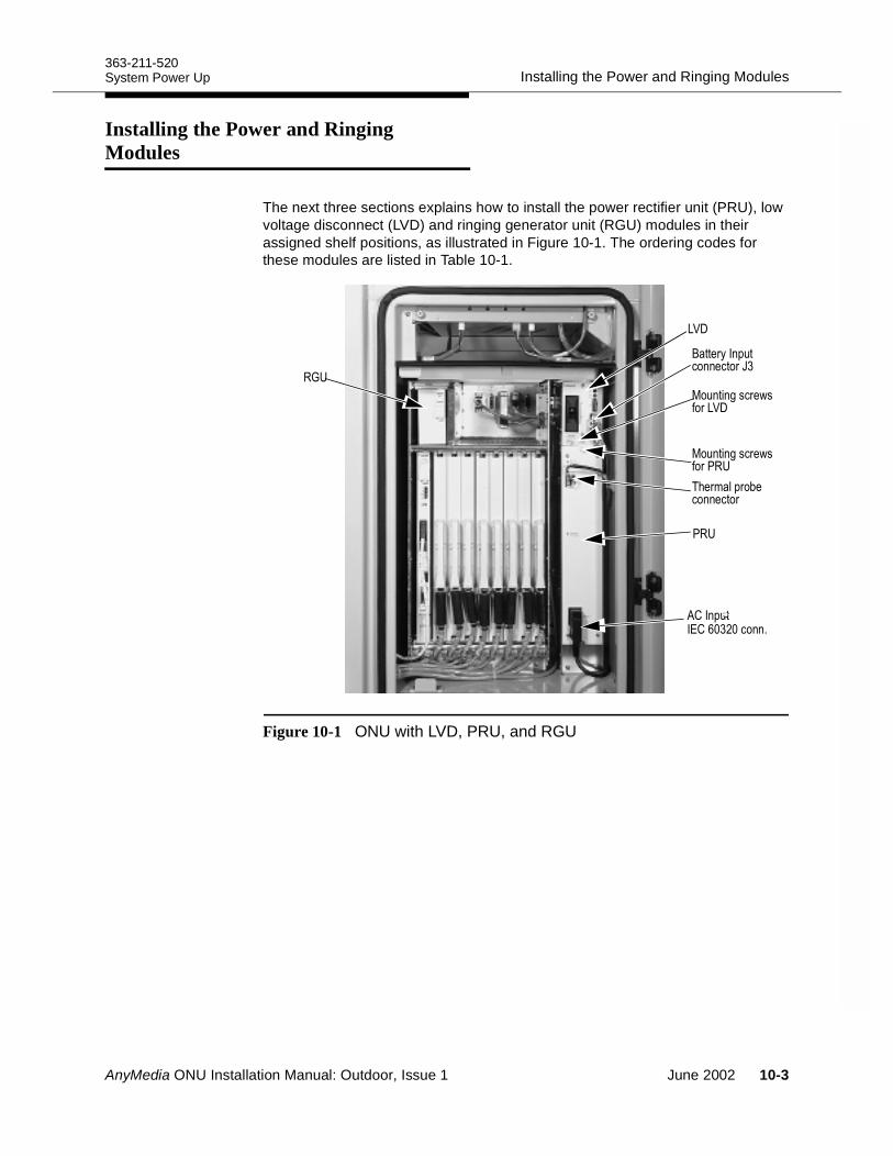
363-211-520Installing the Power and Ringing ModulesSystem Power Up
Installing the Power and Ringing Modules 10
The next three sections explains how to install the power rectifier unit (PRU), low voltage disconnect (LVD) and ringing generator unit (RGU) modules in their assigned shelf positions, as illustrated in Figure 10-1. The ordering codes for these modules are listed in Table 10-1.
Figure 10-1 ONU with LVD, PRU, and RGU
74
3 '9
/+ (
B
" 74
.*:
/+ (" 6.:
8# &
6.:
099A0
≈
AnyMedia ONU Installation Manual: Outdoor, Issue 1 June 2002 10-3
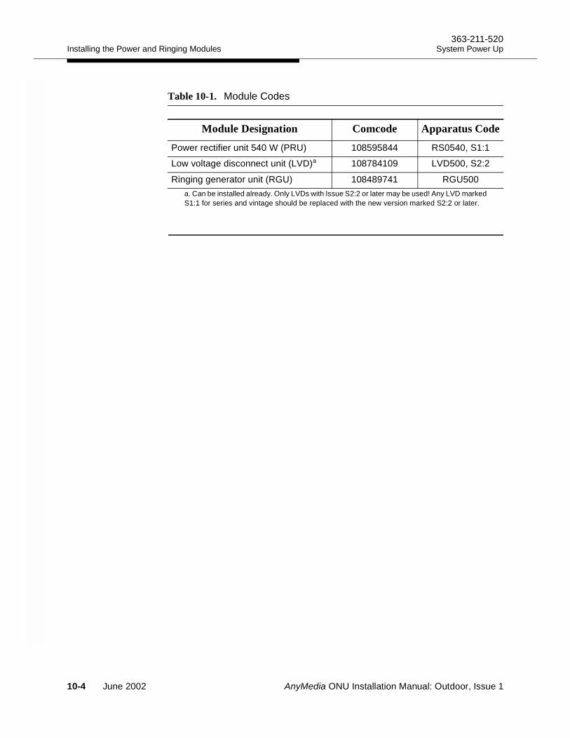
Installing the Power and Ringing Modules363-211-520
System Power Up
Table 10-1. Module Codes
Module Designation Comcode Apparatus Code
Power rectifier unit 540 W (PRU) 108595844 RS0540, S1:1
Low voltage disconnect unit (LVD)a
a. Can be installed already. Only LVDs with Issue S2:2 or later may be used! Any LVD markedS1:1 for series and vintage should be replaced with the new version marked S2:2 or later.
108784109 LVD500, S2:2
Ringing generator unit (RGU) 108489741 RGU500
10-4 June 2002 AnyMedia ONU Installation Manual: Outdoor, Issue 1
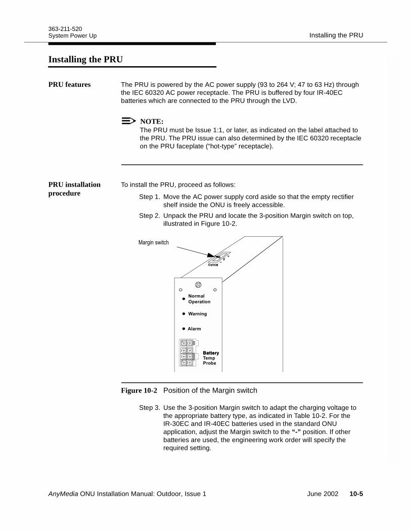
363-211-520Installing the PRUSystem Power Up
Installing the PRU 10
PRU features The PRU is powered by the AC power supply (93 to 264 V; 47 to 63 Hz) through the IEC 60320 AC power receptacle. The PRU is buffered by four IR-40EC batteries which are connected to the PRU through the LVD.
NOTE:The PRU must be Issue 1:1, or later, as indicated on the label attached to the PRU. The PRU issue can also determined by the IEC 60320 receptacle on the PRU faceplate (“hot-type” receptacle).
PRU installation procedure
To install the PRU, proceed as follows:
Step 1. Move the AC power supply cord aside so that the empty rectifier shelf inside the ONU is freely accessible.
Step 2. Unpack the PRU and locate the 3-position Margin switch on top, illustrated in Figure 10-2.
Figure 10-2 Position of the Margin switch
Step 3. Use the 3-position Margin switch to adapt the charging voltage to the appropriate battery type, as indicated in Table 10-2. For the IR-30EC and IR-40EC batteries used in the standard ONU application, adjust the Margin switch to the “-” position. If other batteries are used, the engineering work order will specify the required setting.
.
"
67
.
/ +(#
AnyMedia ONU Installation Manual: Outdoor, Issue 1 June 2002 10-5
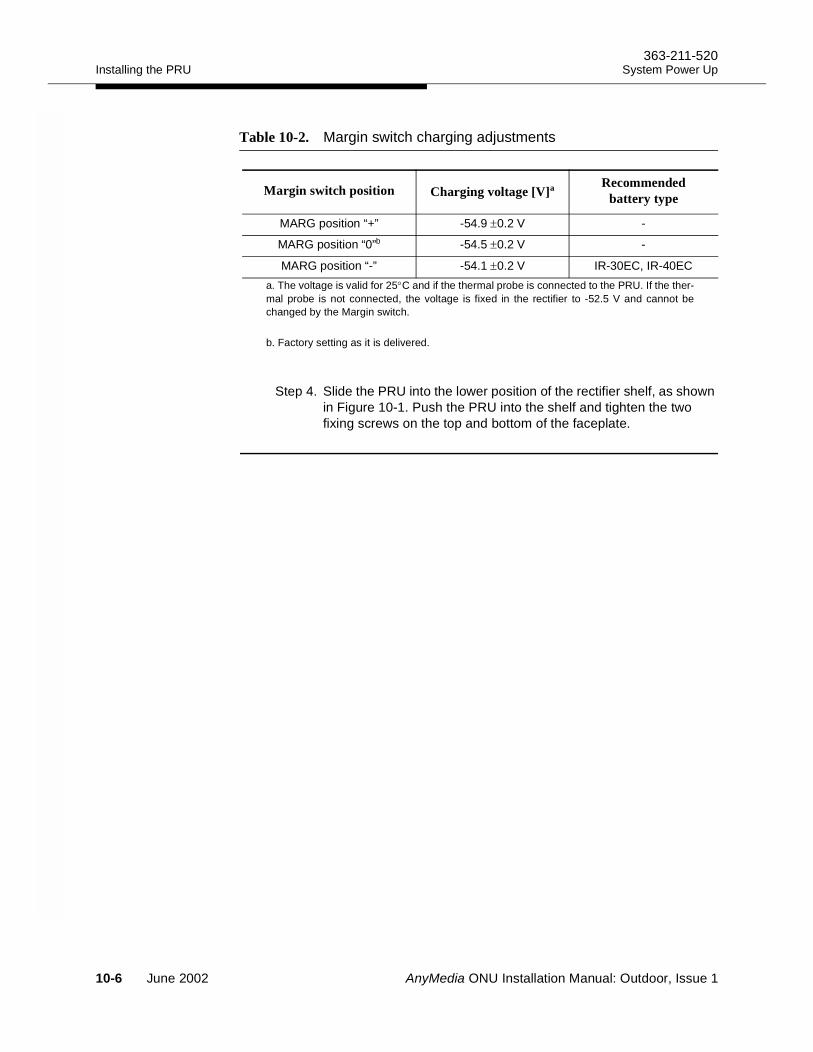
Installing the PRU363-211-520
System Power Up
Step 4. Slide the PRU into the lower position of the rectifier shelf, as shown in Figure 10-1. Push the PRU into the shelf and tighten the two fixing screws on the top and bottom of the faceplate.
Table 10-2. Margin switch charging adjustments
Margin switch position Charging voltage [V]a
a. The voltage is valid for 25°C and if the thermal probe is connected to the PRU. If the ther-mal probe is not connected, the voltage is fixed in the rectifier to -52.5 V and cannot bechanged by the Margin switch.
Recommended battery type
MARG position “+” -54.9 ±0.2 V -
MARG position “0”b
b. Factory setting as it is delivered.
-54.5 ±0.2 V -
MARG position “-” -54.1 ±0.2 V IR-30EC, IR-40EC
10-6 June 2002 AnyMedia ONU Installation Manual: Outdoor, Issue 1
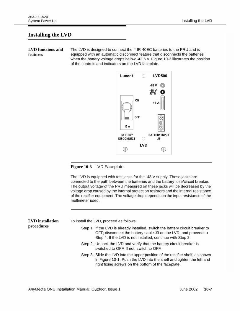
363-211-520Installing the LVDSystem Power Up
Installing the LVD 10
LVD functions and features
The LVD is designed to connect the 4 IR-40EC batteries to the PRU and is equipped with an automatic disconnect feature that disconnects the batteries when the battery voltage drops below -42.5 V. Figure 10-3 illustrates the position of the controls and indicators on the LVD faceplate.
Figure 10-3 LVD Faceplate
The LVD is equipped with test jacks for the -48 V supply. These jacks are connected to the path between the batteries and the battery fuse/circuit breaker. The output voltage of the PRU measured on these jacks will be decreased by the voltage drop caused by the internal protection resistors and the internal resistance of the rectifier equipment. The voltage drop depends on the input resistance of the multimeter used.
LVD installation procedures
To install the LVD, proceed as follows:
Step 1. If the LVD is already installed, switch the battery circuit breaker to OFF, disconnect the battery cable J3 on the LVD, and proceed to Step 4. If the LVD is not installed, continue with Step 2.
Step 2. Unpack the LVD and verify that the battery circuit breaker is switched to OFF. If not, switch to OFF.
Step 3. Slide the LVD into the upper position of the rectifier shelf, as shown in Figure 10-1. Push the LVD into the shelf and tighten the left and right fixing screws on the bottom of the faceplate.
9
8
!$%
&$
!$%
'
9 8 11
28
28"
AnyMedia ONU Installation Manual: Outdoor, Issue 1 June 2002 10-7
Installing the LVD363-211-520
System Power Up
Step 4. Verify that the GMT-type fuse is 15 A. If not, locate the spare 15 A GMT-type fuses (Comcode: 408026243) which have been separately packed and replace the fuse.
WARNING:Do not connect the battery cable to LVD connector J3. If required, disconnect this cable.
10-8 June 2002 AnyMedia ONU Installation Manual: Outdoor, Issue 1
363-211-520Installing the Optional RGUSystem Power Up
Installing the Optional RGU 10
RGU functions To support POTS applications, the ONU shelf must be equipped with the RGU, which is delivered separately. (For ordering see the AnyMedia® Access System (24 Channel) Ordering Guide, 363-211-125.) Jumpers can be used to adjust the RGU ringing frequency, as described in the following installation procedure. The factory setting is 20 Hz.
RGU installation procedure
Use the following procedure to install the RGU:
Step 1. Unpack the RGU and verify that the jumpers are set to 20 Hz. Figure 10-4 illustrates the jumper positions that correspond to the available ringing frequencies.
Step 2. Verify that the latch on the RGU is swung out (OPEN position). If it is not, swing the latch upwards about 90 degrees.
Step 3. Slide the RGU into the upper position of the ONU shelf with the printed board to the right, and push the RGU into the shelf. See Figure 10-1 for the RGU shelf position.
Step 4. Lock the RGU in position by pressing firmly on the rounded indentation on the top latch until it clicks into place.
AnyMedia ONU Installation Manual: Outdoor, Issue 1 June 2002 10-9
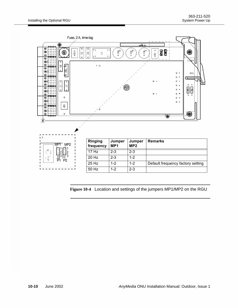
Installing the Optional RGU363-211-520
System Power Up
Figure 10-4 Location and settings of the jumpers MP1/MP2 on the RGU
77
:9
;9
3
;9
3
/&
: C + +
6 C + +
7 C + + "$!'"B$"#(*('*"#/
76 C + +
:'4';
!
1! 1
10-10 June 2002 AnyMedia ONU Installation Manual: Outdoor, Issue 1
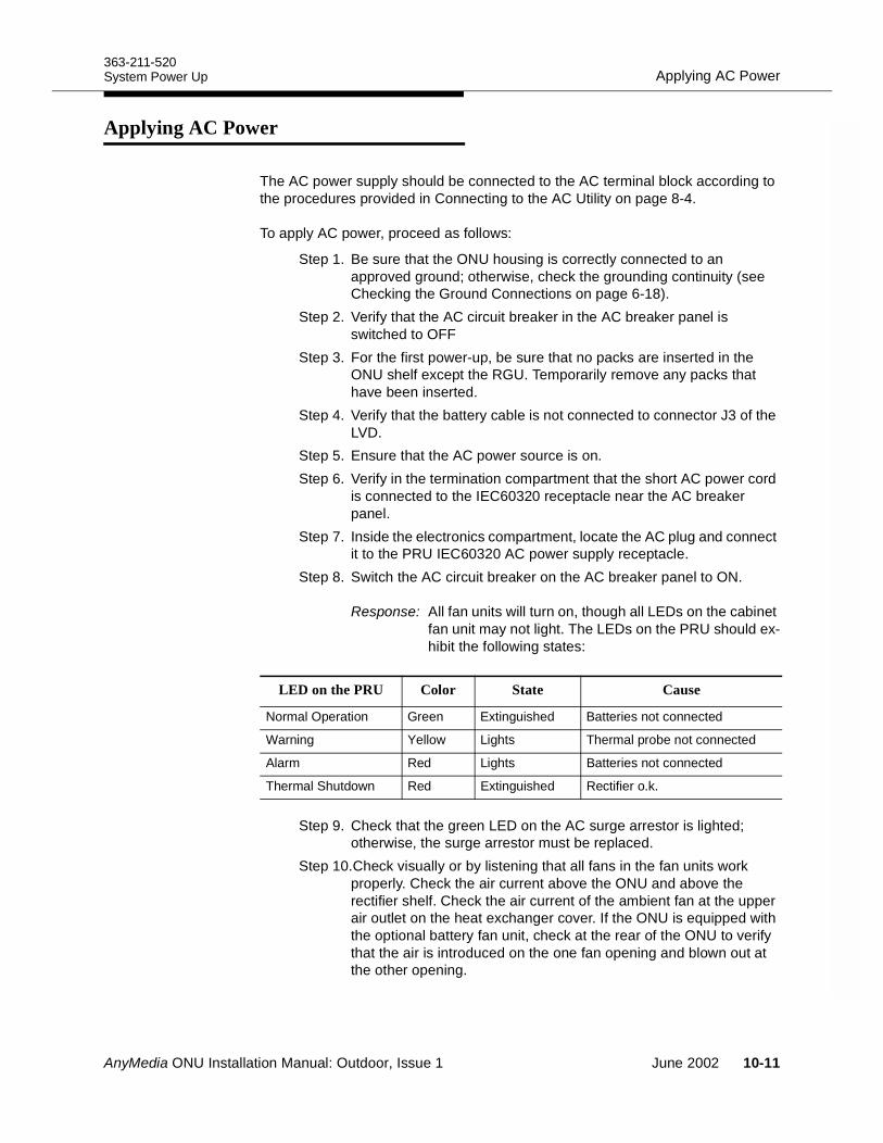
363-211-520Applying AC PowerSystem Power Up
Applying AC Power 10
The AC power supply should be connected to the AC terminal block according to the procedures provided in Connecting to the AC Utility on page 8-4.
To apply AC power, proceed as follows:
Step 1. Be sure that the ONU housing is correctly connected to an approved ground; otherwise, check the grounding continuity (see Checking the Ground Connections on page 6-18).
Step 2. Verify that the AC circuit breaker in the AC breaker panel is switched to OFF
Step 3. For the first power-up, be sure that no packs are inserted in the ONU shelf except the RGU. Temporarily remove any packs that have been inserted.
Step 4. Verify that the battery cable is not connected to connector J3 of the LVD.
Step 5. Ensure that the AC power source is on. Step 6. Verify in the termination compartment that the short AC power cord
is connected to the IEC60320 receptacle near the AC breaker panel.
Step 7. Inside the electronics compartment, locate the AC plug and connect it to the PRU IEC60320 AC power supply receptacle.
Step 8. Switch the AC circuit breaker on the AC breaker panel to ON.
Response: All fan units will turn on, though all LEDs on the cabinet fan unit may not light. The LEDs on the PRU should ex-hibit the following states:
Step 9. Check that the green LED on the AC surge arrestor is lighted; otherwise, the surge arrestor must be replaced.
Step 10.Check visually or by listening that all fans in the fan units work properly. Check the air current above the ONU and above the rectifier shelf. Check the air current of the ambient fan at the upper air outlet on the heat exchanger cover. If the ONU is equipped with the optional battery fan unit, check at the rear of the ONU to verify that the air is introduced on the one fan opening and blown out at the other opening.
LED on the PRU Color State Cause
Normal Operation Green Extinguished Batteries not connected
Warning Yellow Lights Thermal probe not connected
Alarm Red Lights Batteries not connected
Thermal Shutdown Red Extinguished Rectifier o.k.
AnyMedia ONU Installation Manual: Outdoor, Issue 1 June 2002 10-11
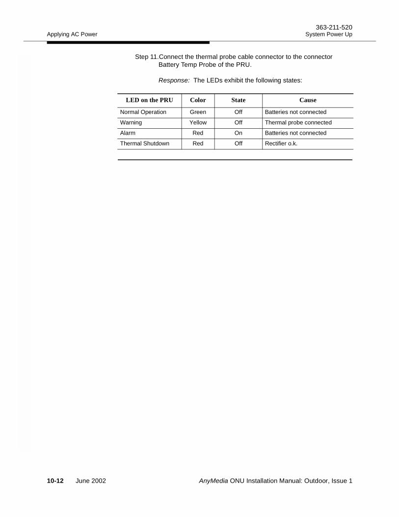
Applying AC Power363-211-520
System Power Up
Step 11.Connect the thermal probe cable connector to the connector Battery Temp Probe of the PRU.
Response: The LEDs exhibit the following states:
LED on the PRU Color State Cause
Normal Operation Green Off Batteries not connected
Warning Yellow Off Thermal probe connected
Alarm Red On Batteries not connected
Thermal Shutdown Red Off Rectifier o.k.
10-12 June 2002 AnyMedia ONU Installation Manual: Outdoor, Issue 1
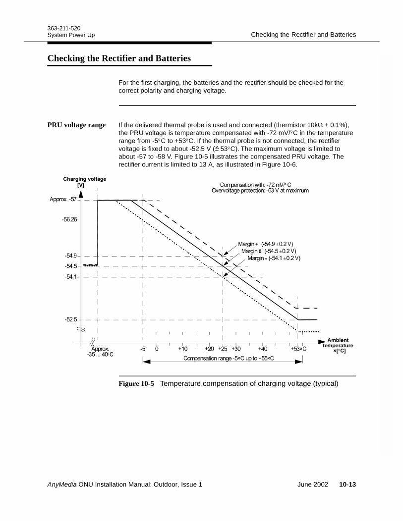
363-211-520Checking the Rectifier and BatteriesSystem Power Up
Checking the Rectifier and Batteries 10
For the first charging, the batteries and the rectifier should be checked for the correct polarity and charging voltage.
PRU voltage range If the delivered thermal probe is used and connected (thermistor 10kΩ ± 0.1%), the PRU voltage is temperature compensated with -72 mV/°C in the temperature range from -5°C to +53°C. If the thermal probe is not connected, the rectifier voltage is fixed to about -52.5 V (= 53°C). The maximum voltage is limited to about -57 to -58 V. Figure 10-5 illustrates the compensated PRU voltage. The rectifier current is limited to 13 A, as illustrated in Figure 10-6.
Figure 10-5 Temperature compensation of charging voltage (typical)
>
;)!
;)?
;""
4;3
>! > >7 >) >7@-;
;
-;@->@-
;)
1 ;)?±A#
1 ;)±A#
1 ;)!±A#
-B;3A/°-
4
<<B;"7 A
°;7)°-
AnyMedia ONU Installation Manual: Outdoor, Issue 1 June 2002 10-13
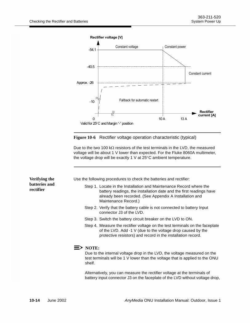
Checking the Rectifier and Batteries363-211-520
System Power Up
Figure 10-6 Rectifier voltage operation characteristic (typical)
Due to the two 100 kΩ resistors of the test terminals in the LVD, the measured voltage will be about 1 V lower than expected. For the Fluke 8060A multimeter, the voltage drop will be exactly 1 V at 25°C ambient temperature.
Verifying the batteries and rectifier
Use the following procedures to check the batteries and rectifier:
Step 1. Locate in the Installation and Maintenance Record where the battery readings, the installation date and the first readings have already been recorded. (See Appendix A Installation and Maintenance Record.)
Step 2. Verify that the battery cable is not connected to battery Input connector J3 of the LVD.
Step 3. Switch the battery circuit breaker on the LVD to ON.Step 4. Measure the rectifier voltage on the test terminals on the faceplate
of the LVD. Add -1 V (due to the voltage drop caused by the protective resistors) and record in the installation record.
NOTE:Due to the internal voltage drop in the LVD, the voltage measured on the test terminals will be 1 V lower than the voltage that is applied to the ONU shelf.
Alternatively, you can measure the rectifier voltage at the terminals of battery input connector J3 on the faceplate of the LVD without voltage drop,
!4 !74
;!
.,/01
4;"
;)
;)!
0$+ 0(
0
<&)"
A°-1C;D
%#/(1
10-14 June 2002 AnyMedia ONU Installation Manual: Outdoor, Issue 1
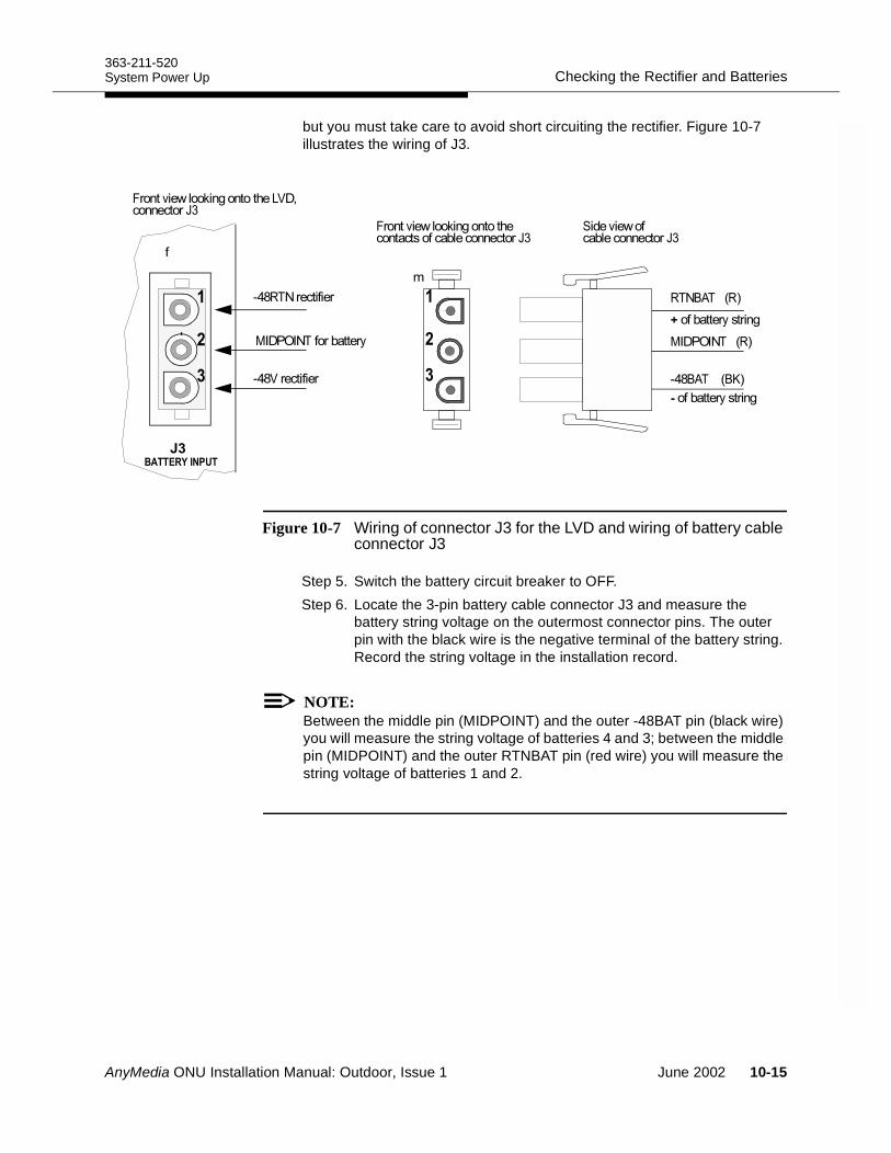
363-211-520Checking the Rectifier and BatteriesSystem Power Up
but you must take care to avoid short circuiting the rectifier. Figure 10-7 illustrates the wiring of J3.
Figure 10-7 Wiring of connector J3 for the LVD and wiring of battery cable connector J3
Step 5. Switch the battery circuit breaker to OFF.Step 6. Locate the 3-pin battery cable connector J3 and measure the
battery string voltage on the outermost connector pins. The outer pin with the black wire is the negative terminal of the battery string. Record the string voltage in the installation record.
NOTE:Between the middle pin (MIDPOINT) and the outer -48BAT pin (black wire) you will measure the string voltage of batteries 4 and 3; between the middle pin (MIDPOINT) and the outer RTNBAT pin (red wire) you will measure the string voltage of batteries 1 and 2.
0+ =4+ 0#
1$*$ + 0#
;)&=4+ =E#
:<,FA*'G7
:<,(G7
5<(G7
;)&A
;)&0+
1$*$ +(8
(8
(8
AnyMedia ONU Installation Manual: Outdoor, Issue 1 June 2002 10-15
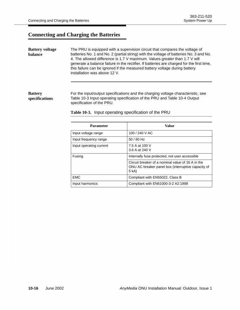
Connecting and Charging the Batteries363-211-520
System Power Up
Connecting and Charging the Batteries10
Battery voltage balance
The PRU is equipped with a supervision circuit that compares the voltage of batteries No. 1 and No. 2 (partial string) with the voltage of batteries No. 3 and No. 4. The allowed difference is 1.7 V maximum. Values greater than 1.7 V will generate a balance failure in the rectifier. If batteries are charged for the first time, this failure can be ignored if the measured battery voltage during battery installation was above 12 V.
Battery specifications
For the input/output specifications and the charging voltage characteristic, see Table 10-3 Input operating specification of the PRU and Table 10-4 Output specification of the PRU.
Table 10-3. Input operating specification of the PRU
Parameter Value
Input voltage range 100 / 240 V AC
Input frequency range 50 / 60 Hz
Input operating current 7.5 A at 100 V3.6 A at 240 V
Fusing Internally fuse protected, not user accessible
Circuit breaker of a nominal value of 16 A in the ONU AC breaker panel box (interruptive capacity of 5 kA)
EMC Compliant with EN55022, Class B
Input harmonics Compliant with EN61000-3-2 A2:1998
10-16 June 2002 AnyMedia ONU Installation Manual: Outdoor, Issue 1
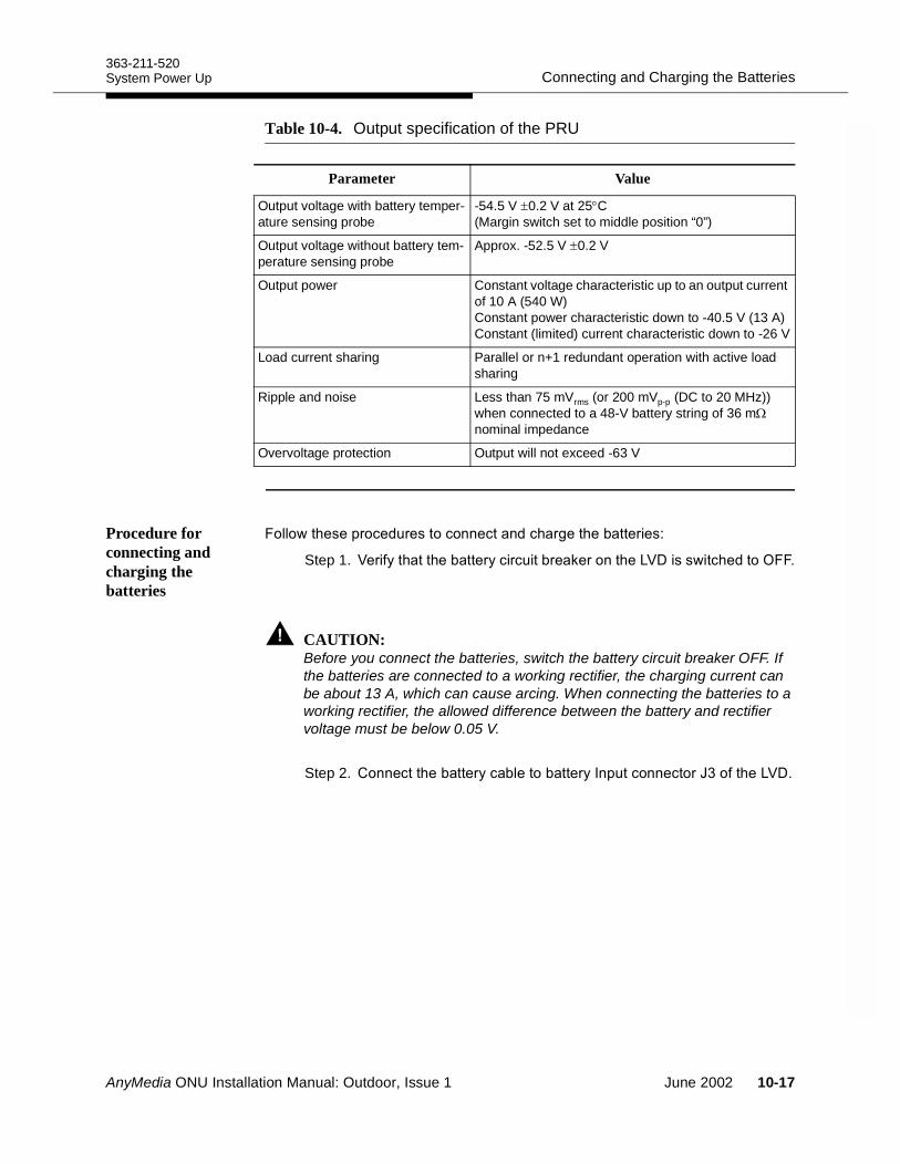
363-211-520Connecting and Charging the BatteriesSystem Power Up
Procedure for connecting and charging the batteries
!!-)""&'("%$'"(##"(#%()'/")" "'"A
Step 1. ?"'*))" "'*('($ '"."'#)"?-()"%
CAUTION:Before you connect the batteries, switch the battery circuit breaker OFF. If the batteries are connected to a working rectifier, the charging current can be about 13 A, which can cause arcing. When connecting the batteries to a working rectifier, the allowed difference between the battery and rectifier voltage must be below 0.05 V.
Step 2. ##"()" "'*( !" "'*#&$(##"('D)"?
Table 10-4. Output specification of the PRU
Parameter Value
Output voltage with battery temper-ature sensing probe
-54.5 V ±0.2 V at 25°C (Margin switch set to middle position “0”)
Output voltage without battery tem-perature sensing probe
Approx. -52.5 V ±0.2 V
Output power Constant voltage characteristic up to an output current of 10 A (540 W)Constant power characteristic down to -40.5 V (13 A)Constant (limited) current characteristic down to -26 V
Load current sharing Parallel or n+1 redundant operation with active load sharing
Ripple and noise Less than 75 mVrms (or 200 mVp-p (DC to 20 MHz)) when connected to a 48-V battery string of 36 mΩ nominal impedance
Overvoltage protection Output will not exceed -63 V
AnyMedia ONU Installation Manual: Outdoor, Issue 1 June 2002 10-17
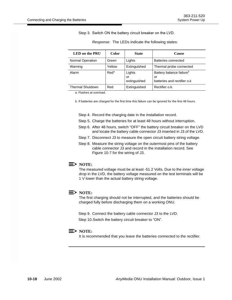
Connecting and Charging the Batteries363-211-520
System Power Up
Step 3. -())" "'*('($ '"."'#)"?
Response: The LEDs indicate the following states:
Step 4. Record the charging date in the installation record.Step 5. Charge the batteries for at least 48 hours without interruption. Step 6. After 48 hours, switch “OFF” the battery circuit breaker on the LVD
and locate the battery cable connector J3 inserted in J3 of the LVD. Step 7. Disconnect J3 to measure the open circuit battery string voltage. Step 8. Measure the string voltage on the outermost pins of the battery
cable connector J3 and record in the installation record. See Figure 10-7 for the wiring of J3.
NOTE:The measured voltage must be at least -51.2 Volts. Due to the inner voltage drop in the LVD, the battery voltage measured on the test terminals will be 1 V lower than the actual battery string voltage.
NOTE:The first charging should not be interrupted, and the batteries should be charged fully before discharging them on a working ONU.
Step 9. Connect the battery cable connector J3 to the LVD.Step 10.Switch the battery circuit breaker to “ON”.
NOTE:It is recommended that you leave the batteries connected to the rectifier.
LED on the PRU Color State Cause
Normal Operation Green Lights Batteries connected
Warning Yellow Extinguished Thermal probe connected
Alarm Reda Lights or extinguished
Battery balance failureb or batteries and rectifier o.k
Thermal Shutdown Red Extinguished Rectifier o.k.a. Flashes at overload.
b. If batteries are charged for the first time this failure can be ignored for the first 48 hours.
10-18 June 2002 AnyMedia ONU Installation Manual: Outdoor, Issue 1
AnyMedia ONU Installation Manual: Outdoor, Issue 1
Fan Unit and Battery Maintenance11Overview 11
This chapter covers the recommended maintenance procedures for the AnyMedia ONU fan units and batteries.
Contents
Page Maintenance Intervals +
Fan units +
Screens and heat exchanger ducts +
Batteries +
Maintenance of the Fan Units +
Cleaning the fan screens +
Cleaning the heat exchanger +
Fan inspection +3
Procedure for replacing the ambient fan +3
Procedure for replacing the cabinet fan unit +;
Procedure for replacing the battery fan unit +<
Battery Maintenance Practice +
Battery safety +
Gas explosion +7
GMT fuses +7
Battery connections +7
June 2002 11-1
Overview363-211-520
Fan Unit and Battery Maintenance
Electrolyte contact +3
Acid spills +7
Battery Maintenance Procedures +3
Maintenance routines +3
Maintenance intervals for IR-40EC batteries +3
Required tools +:
Battery String Float Voltage +;
Determining the float voltage +;
Measuring the voltage of the battery string +;
Battery string measurement procedure +<
Measuring the voltage of a single battery +6
Individual battery measurement procedure +
Battery Compartment Maintenance +
Cleaning and inspecting +
Acid spills and corrosion +
Retorquing inter-battery connections +
Battery Replacement +7
When to replace batteries +7
Procedure for removing and replacing IR-40EC batteries +7
Procedure for replacing the battery heater pad +:
Page
11-2 June 2002 AnyMedia ONU Installation Manual: Outdoor, Issue 1
363-211-520Maintenance IntervalsFan Unit and Battery Maintenance
Maintenance Intervals 11
Fan units Depending on the working conditions, check the fan for replacement after 40,000 working hours (about 4 years and 7 months if working 24 hours a day). If a cabinet or heat exchanger fan alarm occurs attend to the fan units and service them immediately. Replace defective fan units without delay.
Screens and heat exchanger ducts
Check the fan screens and the ducts of the heat exchanger to determine if they need to be cleaned about 2 months after the initial installation and every 6 months thereafter.
If the high temperature alarm occurs, immediately attend to the heat exchanger and the heat exchanger fan. This procedure should only be performed when the ambient temperature is below +131° F (55° C).
Batteries The batteries must be maintained quarterly and the Installation and Maintenance Record must be filled out and signed. The Installation and Maintenance Record is used to record measurable parameters during maintenance work, and the completed forms will be required for any future warranty claims. IR-40EC batteries have a guaranteed lifetime of 5 years and should be replaced after that interval to ensure reliable performance. Replace the batteries sooner if the ambient temperature is consistently above 77° F (25°C).
NOTE:Operating the IR-40EC battery for any length of time above 77° F (25°C) will result in reduced performance and premature failure. Operation or storage for a significant interval of time above 122° F (50°C) may reduce or void the product warranty.
AnyMedia ONU Installation Manual: Outdoor, Issue 1 June 2002 11-3
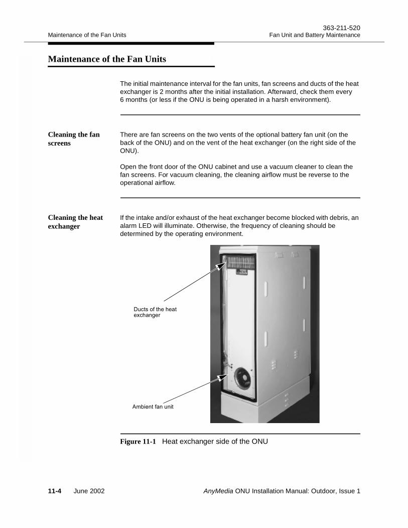
Maintenance of the Fan Units363-211-520
Fan Unit and Battery Maintenance
Maintenance of the Fan Units 11
The initial maintenance interval for the fan units, fan screens and ducts of the heat exchanger is 2 months after the initial installation. Afterward, check them every 6 months (or less if the ONU is being operated in a harsh environment).
Cleaning the fan screens
There are fan screens on the two vents of the optional battery fan unit (on the back of the ONU) and on the vent of the heat exchanger (on the right side of the ONU).
Open the front door of the ONU cabinet and use a vacuum cleaner to clean the fan screens. For vacuum cleaning, the cleaning airflow must be reverse to the operational airflow.
Cleaning the heat exchanger
If the intake and/or exhaust of the heat exchanger become blocked with debris, an alarm LED will illuminate. Otherwise, the frequency of cleaning should be determined by the operating environment.
Figure 11-1 Heat exchanger side of the ONU
$()")"
, "##$#
"9()#/"'
11-4 June 2002 AnyMedia ONU Installation Manual: Outdoor, Issue 1
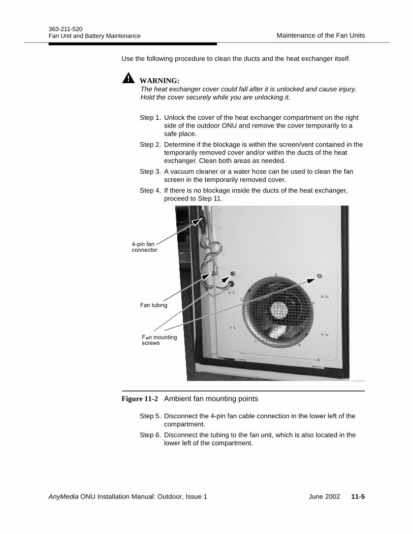
363-211-520Maintenance of the Fan UnitsFan Unit and Battery Maintenance
Use the following procedure to clean the ducts and the heat exchanger itself.
WARNING:The heat exchanger cover could fall after it is unlocked and cause injury. Hold the cover securely while you are unlocking it.
Step 1. Unlock the cover of the heat exchanger compartment on the right side of the outdoor ONU and remove the cover temporarily to a safe place.
Step 2. Determine if the blockage is within the screen/vent contained in the temporarily removed cover and/or within the ducts of the heat exchanger. Clean both areas as needed.
Step 3. A vacuum cleaner or a water hose can be used to clean the fan screen in the temporarily removed cover.
Step 4. If there is no blockage inside the ducts of the heat exchanger, proceed to Step 11.
Figure 11-2 Ambient fan mounting points
Step 5. Disconnect the 4-pin fan cable connection in the lower left of the compartment.
Step 6. Disconnect the tubing to the fan unit, which is also located in the lower left of the compartment.
+&##
#$ #/
(##"('
#,$##/('"-
AnyMedia ONU Installation Manual: Outdoor, Issue 1 June 2002 11-5
Maintenance of the Fan Units363-211-520
Fan Unit and Battery Maintenance
Step 7. Using a standard screwdriver, loosen the captive screws holding the ambient fan unit in place.
Step 8. Remove the ambient fan unit by loosening the fasteners completely and tilt the unit out until it clears the heat exchanger.
Step 9. If required, clean the ambient fan unit with a vacuum cleaner and/or with a paintbrush.
Step 10.A standard water hose can be used to remove any accumulated debris inside the ducts of the heat exchanger.
NOTE:Do not use a tool of any kind within the ducts of the heat exchanger to remove debris, as this may cause a puncture in the thin copper wall tubing.
Step 11.Install the ambient fan unit in the same manner as it was removed, by setting the bottom tabs first and tilting the unit up until the captive screws can be engaged.
Step 12.Tighten the two fasteners with the screwdriver.Step 13.Connect the tubing to the fitting on the fan unit.Step 14.Connect the 4-pin fan cable connection disconnected in Step 5.Step 15.Verify that the alarm signal on the cabinet fan unit has
extinguished.Step 16.Reinstall the heat exchanger cover.
Fan inspection During inspection of the vents and/or fan screens check the optional battery fans and the ambient fan of the heat exchanger for debris.
Procedure for replacing the ambient fan
An alarm LED will illuminate if a fan fails within the heat exchanger unit. If the ambient fan unit is defective, it must be replaced immediately. To ensure reliable cooling, replace the ambient fan unit after 40,000 working hours
Use the following procedure to remove and replace the fan unit without service interruption:
Step 1. Unlock the heat exchanger cover of the heat exchanger compartment on the right side of the ONU and remove the cover temporarily to a safe place.
11-6 June 2002 AnyMedia ONU Installation Manual: Outdoor, Issue 1
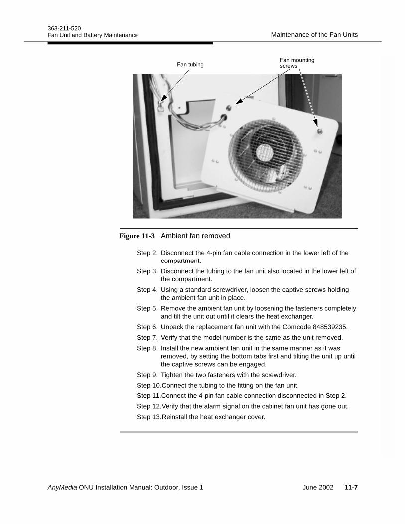
363-211-520Maintenance of the Fan UnitsFan Unit and Battery Maintenance
Figure 11-3 Ambient fan removed
Step 2. Disconnect the 4-pin fan cable connection in the lower left of the compartment.
Step 3. Disconnect the tubing to the fan unit also located in the lower left of the compartment.
Step 4. Using a standard screwdriver, loosen the captive screws holding the ambient fan unit in place.
Step 5. Remove the ambient fan unit by loosening the fasteners completely and tilt the unit out until it clears the heat exchanger.
Step 6. Unpack the replacement fan unit with the Comcode 848539235.Step 7. Verify that the model number is the same as the unit removed.Step 8. Install the new ambient fan unit in the same manner as it was
removed, by setting the bottom tabs first and tilting the unit up until the captive screws can be engaged.
Step 9. Tighten the two fasteners with the screwdriver.Step 10.Connect the tubing to the fitting on the fan unit.Step 11.Connect the 4-pin fan cable connection disconnected in Step 2.Step 12.Verify that the alarm signal on the cabinet fan unit has gone out.Step 13.Reinstall the heat exchanger cover.
#$ #/#,$##/('"-
AnyMedia ONU Installation Manual: Outdoor, Issue 1 June 2002 11-7
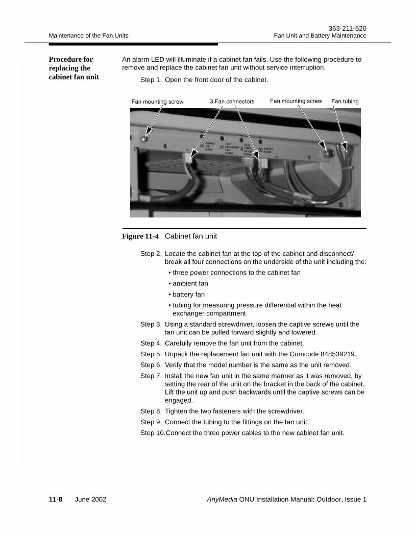
Maintenance of the Fan Units363-211-520
Fan Unit and Battery Maintenance
Procedure for replacing the cabinet fan unit
An alarm LED will illuminate if a cabinet fan fails. Use the following procedure to remove and replace the cabinet fan unit without service interruption.
Step 1. Open the front door of the cabinet.
Figure 11-4 Cabinet fan unit
Step 2. Locate the cabinet fan at the top of the cabinet and disconnect/break all four connections on the underside of the unit including the:• three power connections to the cabinet fan• ambient fan• battery fan• tubing for measuring pressure differential within the heat
exchanger compartmentStep 3. Using a standard screwdriver, loosen the captive screws until the
fan unit can be pulled forward slightly and lowered.Step 4. Carefully remove the fan unit from the cabinet.Step 5. Unpack the replacement fan unit with the Comcode 848539219.Step 6. Verify that the model number is the same as the unit removed.Step 7. Install the new fan unit in the same manner as it was removed, by
setting the rear of the unit on the bracket in the back of the cabinet. Lift the unit up and push backwards until the captive screws can be engaged.
Step 8. Tighten the two fasteners with the screwdriver.Step 9. Connect the tubing to the fittings on the fan unit.Step 10.Connect the three power cables to the new cabinet fan unit.
#$ #/#,$##/('"-#(##"('#,$##/('"-
11-8 June 2002 AnyMedia ONU Installation Manual: Outdoor, Issue 1
363-211-520Maintenance of the Fan UnitsFan Unit and Battery Maintenance
Step 11.Verify that the alarm signal on the cabinet fan unit has gone out.Step 12.Close the front door of the cabinet.
Procedure for replacing the battery fan unit
An alarm LED will illuminate if a battery fan unit fails. Use the following procedure to remove and replace the battery fan unit without service interruption.
Step 1. Open the front door of the cabinet.Step 2. On the low voltage disconnect unit (LVD) in the upper part of the
rectifier shelf ensure that the battery circuit breaker is switched “OFF.” For the location of the LVD and the other parts see Installing the Power and Ringing Modules on page 10-3.
Step 3. Disconnect the battery connector J3 on the LVD temporarily.Step 4. Loosen the wing nut above the battery hold down bracket and
remove the bracket.Step 5. Disconnect all four IR-40EC batteries from the battery string cable.Step 6. Remove the ring lug thermistor probe of the temperature
compensation cable from the casing of the battery.Step 7. Remove the batteries temporarily in reverse order as they are
numbered: 4, 3, 2, 1. Temporarily remove the long threaded rod.
NOTE:Do not grip the rod at the top. Grip it only by the middle or lower portion.
Step 8. Disconnect the power connection J2 to the battery fan unit in the middle of the fan controller board.
AnyMedia ONU Installation Manual: Outdoor, Issue 1 June 2002 11-9
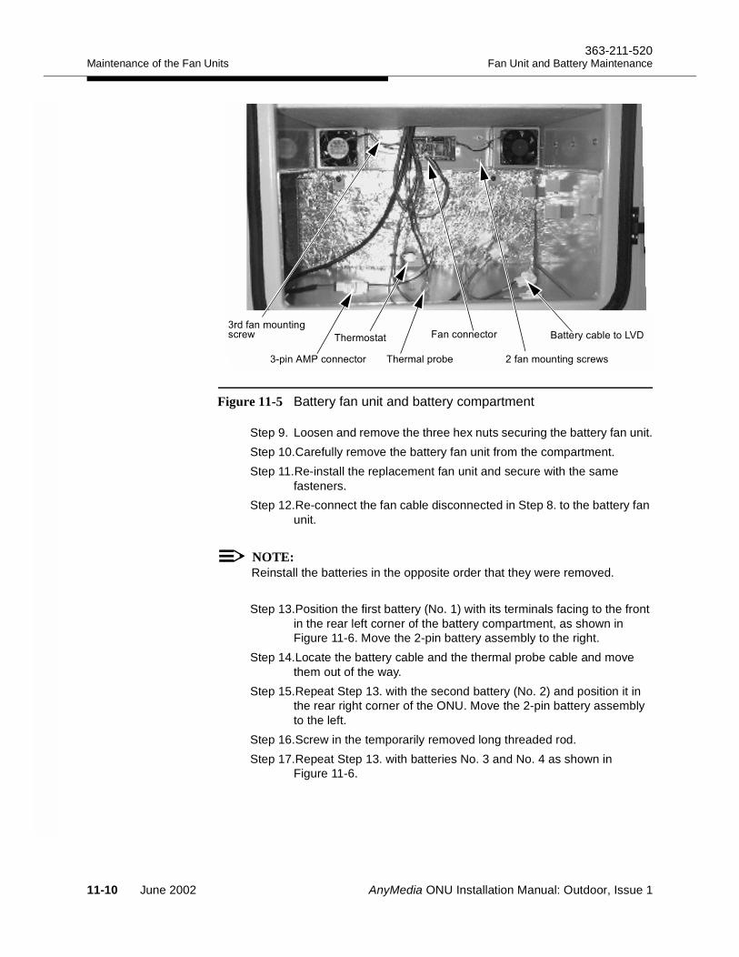
Maintenance of the Fan Units363-211-520
Fan Unit and Battery Maintenance
Figure 11-5 Battery fan unit and battery compartment
Step 9. Loosen and remove the three hex nuts securing the battery fan unit.Step 10.Carefully remove the battery fan unit from the compartment.Step 11.Re-install the replacement fan unit and secure with the same
fasteners.Step 12.Re-connect the fan cable disconnected in Step 8. to the battery fan
unit.
NOTE:Reinstall the batteries in the opposite order that they were removed.
Step 13.Position the first battery (No. 1) with its terminals facing to the front in the rear left corner of the battery compartment, as shown in Figure 11-6. Move the 2-pin battery assembly to the right.
Step 14.Locate the battery cable and the thermal probe cable and move them out of the way.
Step 15.Repeat Step 13. with the second battery (No. 2) and position it in the rear right corner of the ONU. Move the 2-pin battery assembly to the left.
Step 16.Screw in the temporarily removed long threaded rod.Step 17.Repeat Step 13. with batteries No. 3 and No. 4 as shown in
Figure 11-6.
#(##"('
#,$##/('"-
8"'*( !"?
)"',!&' "+&# (##"('
)"',
'%#,$##/('"-
11-10 June 2002 AnyMedia ONU Installation Manual: Outdoor, Issue 1
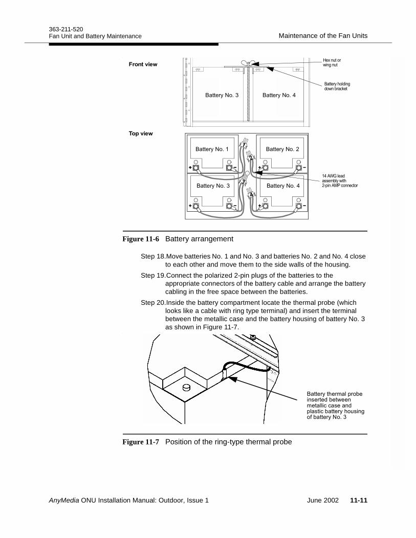
363-211-520Maintenance of the Fan UnitsFan Unit and Battery Maintenance
.
Figure 11-6 Battery arrangement
Step 18.Move batteries No. 1 and No. 3 and batteries No. 2 and No. 4 close to each other and move them to the side walls of the housing.
Step 19.Connect the polarized 2-pin plugs of the batteries to the appropriate connectors of the battery cable and arrange the battery cabling in the free space between the batteries.
Step 20.Inside the battery compartment locate the thermal probe (which looks like a cable with ring type terminal) and insert the terminal between the metallic case and the battery housing of battery No. 3 as shown in Figure 11-7.
.
Figure 11-7 Position of the ring-type thermal probe
(1*- (1*-
(1*-;(1*-<
!
" #!
(1*-< (1*-;
#$%
&'()$# &*+
8"'*)"',!&' "#"'"% "-""#,"!!(("#%&!( "'*)$#/ "'*
AnyMedia ONU Installation Manual: Outdoor, Issue 1 June 2002 11-11
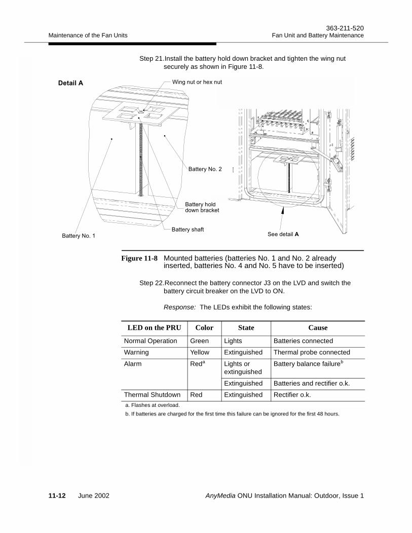
Maintenance of the Fan Units363-211-520
Fan Unit and Battery Maintenance
Step 21.Install the battery hold down bracket and tighten the wing nut securely as shown in Figure 11-8.
Figure 11-8 Mounted batteries (batteries No. 1 and No. 2 already inserted, batteries No. 4 and No. 5 have to be inserted)
Step 22.Reconnect the battery connector J3 on the LVD and switch the battery circuit breaker on the LVD to ON.
Response: The LEDs exhibit the following states:
8"'*)!%%-# '(."
8"'*)
8"'*
8"'*
""%"!
4#/#$')"9#$
LED on the PRU Color State Cause
Normal Operation Green Lights Batteries connected
Warning Yellow Extinguished Thermal probe connected
Alarm Reda Lights or extinguished
Battery balance failureb
Extinguished Batteries and rectifier o.k.
Thermal Shutdown Red Extinguished Rectifier o.k.a. Flashes at overload.b. If batteries are charged for the first time this failure can be ignored for the first 48 hours.
11-12 June 2002 AnyMedia ONU Installation Manual: Outdoor, Issue 1

363-211-520Maintenance of the Fan UnitsFan Unit and Battery Maintenance
Step 23.Verify that there are illuminated red alarm LEDs on the power rectifier unit.
Step 24.Close the front door of the cabinet.
AnyMedia ONU Installation Manual: Outdoor, Issue 1 June 2002 11-13
Battery Maintenance Practice363-211-520
Fan Unit and Battery Maintenance
Battery Maintenance Practice 11
Battery safety For safe battery handling, always take the following basic precautions:
Use only properly insulated tools and test equipment.
Remove all metallic objects (key chains, glasses, rings, watches, or any other jewelry).
Wear safety glasses.
Test circuits before touching.
Lock out and tag any circuit breakers/fuses when possible to prevent accidental turn-on.
Be aware of potential hazards before servicing equipment.
Identify exposed hazardous electrical voltages on connectors, wiring, etc. (Note the condition of these circuits, especially any wiring.)
Take care when removing or replacing any covers. Avoid contacting any circuits.
For cleaning batteries use a damp soft cloth only. Do not use solvents, paraffin, abrasive or proprietary cleaning fluids.
DANGER:A battery short circuit will cause destruction by arcing of batteries and cables and thus malfunctioning of the complete system.
Be aware of potential hazards before servicing battery equipment.
You must always use properly insulated tools and test equipment for installing and connecting batteries.
When working on batteries always wear splash-proof safety goggles, acid-resistant gloves, rubber overshoes and an apron.
While maintaining the batteries, you must:
Never place metal objects (including tools) on top of a battery.
Never short out the battery terminals.
Never use an open flame near batteries.
11-14 June 2002 AnyMedia ONU Installation Manual: Outdoor, Issue 1
363-211-520Battery Maintenance PracticeFan Unit and Battery Maintenance
Gas explosion All lead-acid batteries generate hydrogen gas, even under open circuit conditions. If not permitted to escape, this gas can build up to explosive concentrations.
NOTE:Mechanical power switches and electrostatic voltages are sources of spark gaps!
An explosion can occur when sparks are created near the battery string. To avoid sparks, check that the batteries are not charging or discharging before loosening or removing battery connections. Provide adequate ventilation.
GMT fuses The GMT-type fuses in the low voltage disconnect unit (LVD) can produce sparks during interruption or clearing of a fault on a high energy circuit. Use only GMT fuses specified by Lucent Technologies.
Battery connections To avoid loose connections, take care to avoid stripping the bolt and/or nut threads by overtightening the inter-battery connectors.
Electrolyte contact In the event of electrolyte contact with the skin, remove the electrolyte immediately by rinsing the affected area with large amounts of plain tap water. In the event of electrolyte contact with an eye, allow at least one liter of water to run over the eye and under the eyelid. Eye injuries should be treated by a physician immediately.
Acid spills If large acid spill occurs, use agricultural or industrial lime instead of soda to neutralize the acid before cleanup. If lime is not available, you may use baking soda. Wear eye protection devices and rubber gloves when using lime on electrolyte spills. Sprinkle the lime on the spillage; allow it to absorb the electrolyte, and then sweep it up and dispose of it safely, according to local regulations. Wash hands and face thoroughly after cleanup.
AnyMedia ONU Installation Manual: Outdoor, Issue 1 June 2002 11-15
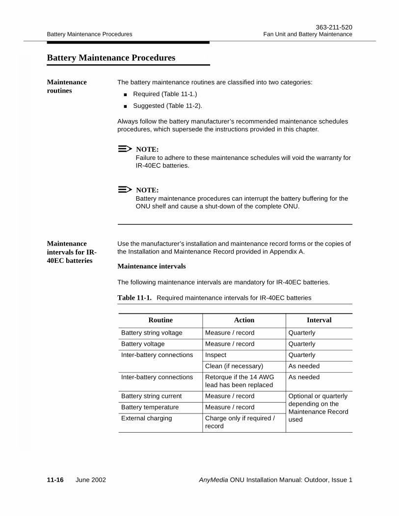
Battery Maintenance Procedures363-211-520
Fan Unit and Battery Maintenance
Battery Maintenance Procedures 11
Maintenance routines
The battery maintenance routines are classified into two categories:
Required (Table 11-1.)
Suggested (Table 11-2).
Always follow the battery manufacturer’s recommended maintenance schedules procedures, which supersede the instructions provided in this chapter.
NOTE:Failure to adhere to these maintenance schedules will void the warranty for IR-40EC batteries.
NOTE:Battery maintenance procedures can interrupt the battery buffering for the ONU shelf and cause a shut-down of the complete ONU.
Maintenance intervals for IR-40EC batteries
Use the manufacturer’s installation and maintenance record forms or the copies of the Installation and Maintenance Record provided in Appendix A.
Maintenance intervals 11
The following maintenance intervals are mandatory for IR-40EC batteries.
Table 11-1. Required maintenance intervals for IR-40EC batteries
Routine Action Interval
Battery string voltage Measure / record Quarterly
Battery voltage Measure / record Quarterly
Inter-battery connections Inspect Quarterly
Clean (if necessary) As needed
Inter-battery connections Retorque if the 14 AWG lead has been replaced
As needed
Battery string current Measure / record Optional or quarterly depending on the Maintenance Record used
Battery temperature Measure / record
External charging Charge only if required / record
11-16 June 2002 AnyMedia ONU Installation Manual: Outdoor, Issue 1
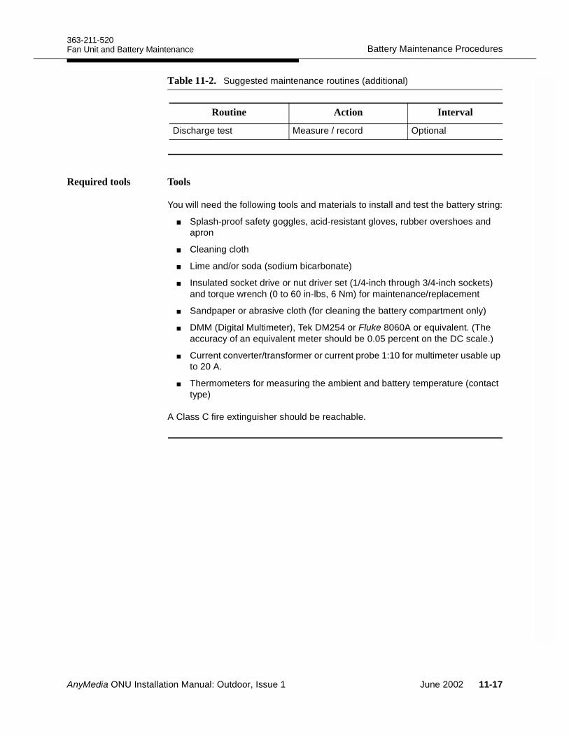
363-211-520Battery Maintenance ProceduresFan Unit and Battery Maintenance
Required tools Tools 11
You will need the following tools and materials to install and test the battery string:
Splash-proof safety goggles, acid-resistant gloves, rubber overshoes and apron
Cleaning cloth
Lime and/or soda (sodium bicarbonate)
Insulated socket drive or nut driver set (1/4-inch through 3/4-inch sockets) and torque wrench (0 to 60 in-lbs, 6 Nm) for maintenance/replacement
Sandpaper or abrasive cloth (for cleaning the battery compartment only)
DMM (Digital Multimeter), Tek DM254 or Fluke 8060A or equivalent. (The accuracy of an equivalent meter should be 0.05 percent on the DC scale.)
Current converter/transformer or current probe 1:10 for multimeter usable up to 20 A.
Thermometers for measuring the ambient and battery temperature (contact type)
A Class C fire extinguisher should be reachable.
Table 11-2. Suggested maintenance routines (additional)
Routine Action Interval
Discharge test Measure / record Optional
AnyMedia ONU Installation Manual: Outdoor, Issue 1 June 2002 11-17
Battery String Float Voltage363-211-520
Fan Unit and Battery Maintenance
Battery String Float Voltage 11
Determining the float voltage
To ensure safe and efficient battery operation, always maintain the battery at the proper float voltage, which is determined as follows:
Battery string voltage = recommended float voltage per battery × number of batteries.
The float voltage required is ambient temperature dependent. The PRU will adapt this charging voltage with -72 mV/°C, as illustrated in Figure 10-5 on page 10-13. The recommended float voltage per IR-40EC battery is 13.5 V ±0.06 V at a battery temperature of 77°F (25°C).
For example, a 4-battery string of IR-40EC batteries should be floated at:
Battery string voltage = 13.5 V × 4 batteries = 54.0 V ±0.24 V
NOTE:The required charging voltage is different for other battery types. Always use the values provided by the battery manufacturer).
Measuring the voltage of the battery string
Read battery string voltages periodically to ensure that they are floating properly. A Fluke 8060A DMM (digital multimeter) is suitable for battery voltage readings. The accuracy of an equivalent meter should be 0.05 percent on the DC scale. Check the meter periodically for accuracy and calibration.
You may use either of the following methods to measure the string voltage on the battery cable connector J3:
Measure on the wiring side of the battery cable connector J3 plugged in the LVD by inserting the probes into the opening for the wires using small test probes
Measure on the contact side of the battery cable connector J3 disconnected from the LVD by inserting the probes into the contacts.
CAUTION:Be aware that maintenance actions will interrupt the battery buffering for the ONU Shelf if the battery circuit breaker is switched OFF and J3 is disconnected. A loss of AC power during these maintenance procedures will cause a shut-down of the complete ONU.
11-18 June 2002 AnyMedia ONU Installation Manual: Outdoor, Issue 1
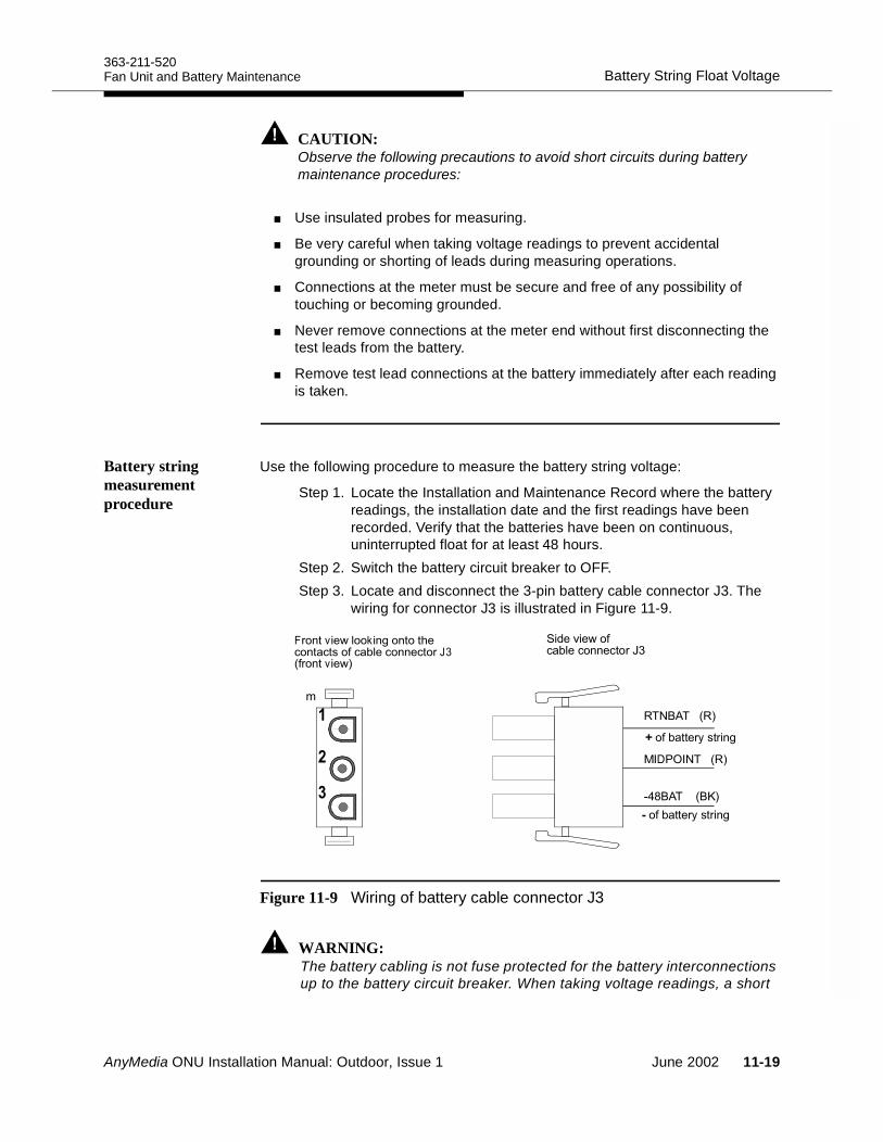
363-211-520Battery String Float VoltageFan Unit and Battery Maintenance
CAUTION:Observe the following precautions to avoid short circuits during battery maintenance procedures:
Use insulated probes for measuring.
Be very careful when taking voltage readings to prevent accidental grounding or shorting of leads during measuring operations.
Connections at the meter must be secure and free of any possibility of touching or becoming grounded.
Never remove connections at the meter end without first disconnecting the test leads from the battery.
Remove test lead connections at the battery immediately after each reading is taken.
Battery string measurement procedure
Use the following procedure to measure the battery string voltage:
Step 1. Locate the Installation and Maintenance Record where the battery readings, the installation date and the first readings have been recorded. Verify that the batteries have been on continuous, uninterrupted float for at least 48 hours.
Step 2. Switch the battery circuit breaker to OFF.Step 3. Locate and disconnect the 3-pin battery cable connector J3. The
wiring for connector J3 is illustrated in Figure 11-9.
Figure 11-9 Wiring of battery cable connector J3
WARNING:The battery cabling is not fuse protected for the battery interconnections up to the battery circuit breaker. When taking voltage readings, a short
*(& !$
9=3')=* !$
;#(& !(>$
:<,(G7 <#
.? @<
1
1
AnyMedia ONU Installation Manual: Outdoor, Issue 1 June 2002 11-19
Battery String Float Voltage363-211-520
Fan Unit and Battery Maintenance
in this area can cause an arc that will destroy batteries and cables, leading to malfunctioning of the complete ONU.
Step 4. Measure the battery string voltage on the outermost connector pins. The outer pin with the black wire is the negative terminal of the battery string. Measure the string voltage of batteries 4 and 3 between the middle pin and the outer “-” pin (black wire).Measure the string voltage of batteries 1 and 2 between the middle pin and the outer “+” pin (red wire).
Requirement: The string voltage must be at least: 51.2 V.
Step 5. Record the string voltage in the Installation and Maintenance Record.
You can also measure the string voltage without interrupting the buffering by measuring on the wiring side of the battery cable connector J3 plugged in the LVD by inserting the probes into the opening for the wires using small test probes.
Measuring the voltage of a single battery
Measure the individual battery voltages periodically to ensure that they are floating properly. Readings for each battery must be within ±0.18 V of the string average (calculated by dividing the string voltage by the number of batteries in the string).
Additionally the power rectifier unit is equipped with a supervision component that compares the voltage of batteries 1 and 2 (1st partial string) to the voltage of batteries 3 and 4 (2nd partial string).
To measure battery voltage, the battery string must be disconnected from the rectifier.
CAUTION:Be aware that maintenance actions will interrupt the battery buffering for the ONU Shelf if the battery circuit breaker is switched OFF and J3 is disconnected. A loss of AC power during these maintenance procedures will cause a shut-down of the complete ONU.
11-20 June 2002 AnyMedia ONU Installation Manual: Outdoor, Issue 1
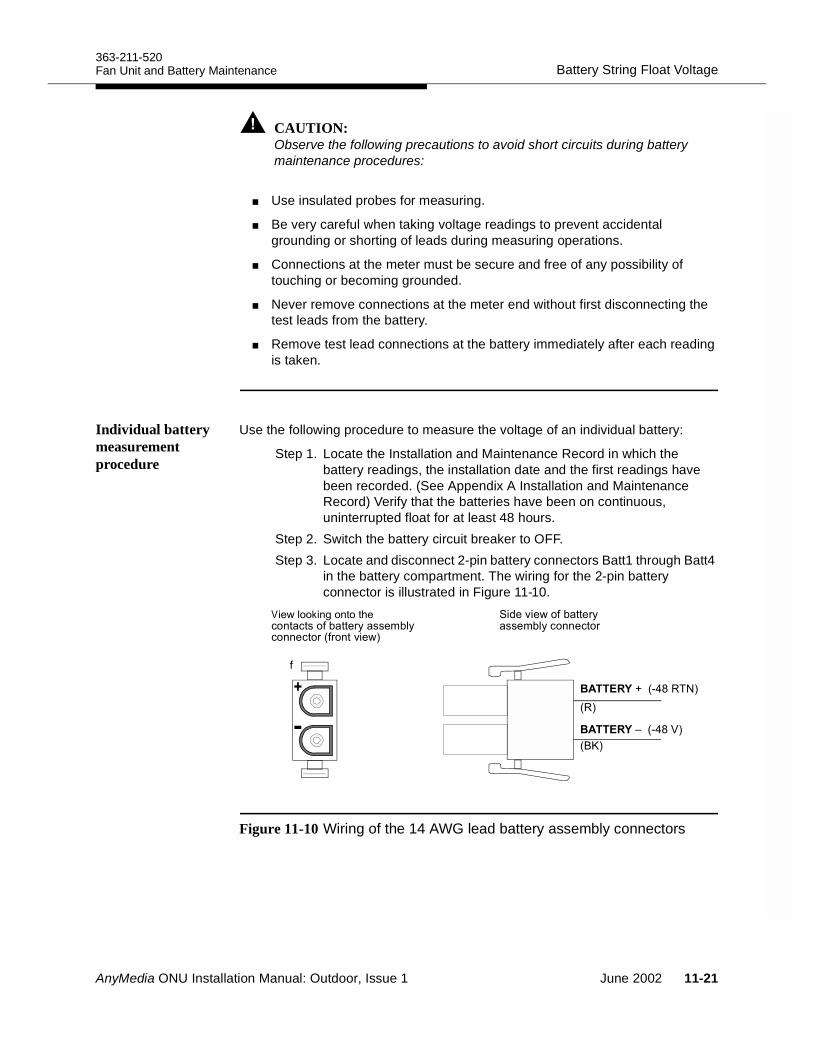
363-211-520Battery String Float VoltageFan Unit and Battery Maintenance
CAUTION:Observe the following precautions to avoid short circuits during battery maintenance procedures:
Use insulated probes for measuring.
Be very careful when taking voltage readings to prevent accidental grounding or shorting of leads during measuring operations.
Connections at the meter must be secure and free of any possibility of touching or becoming grounded.
Never remove connections at the meter end without first disconnecting the test leads from the battery.
Remove test lead connections at the battery immediately after each reading is taken.
Individual battery measurement procedure
Use the following procedure to measure the voltage of an individual battery:
Step 1. Locate the Installation and Maintenance Record in which the battery readings, the installation date and the first readings have been recorded. (See Appendix A Installation and Maintenance Record) Verify that the batteries have been on continuous, uninterrupted float for at least 48 hours.
Step 2. Switch the battery circuit breaker to OFF.Step 3. Locate and disconnect 2-pin battery connectors Batt1 through Batt4
in the battery compartment. The wiring for the 2-pin battery connector is illustrated in Figure 11-10.
Figure 11-10 Wiring of the 14 AWG lead battery assembly connectors
(
.#<E 0+;2
.#<F 0+;?2
A,(#( "'*", !*(##"('0'#="-2
%"="- "'*", !*(##"('
02
08G2
AnyMedia ONU Installation Manual: Outdoor, Issue 1 June 2002 11-21
Battery String Float Voltage363-211-520
Fan Unit and Battery Maintenance
WARNING:The battery cabling is not fuse protected for the battery interconnections up to the battery circuit breaker. When taking voltage readings, a short in this area can cause an arc that will destroy batteries and cables, leading to malfunctioning of the complete ONU.
Step 4. Measure the battery voltage for each battery on the 2-pin 14 AWG lead assembly connector and record the battery voltage in the Installation and Maintenance Record.Because float readings are affected by discharges and recharges, these readings must be taken when the batteries have been on continuous, uninterrupted float for at least one week.
NOTE:Any fully charged IR-40EC battery at float that reads less than 13 V at 77°F (25°C) is considered to be shorted and must be replaced*. For battery replacement procedures, see Battery Replacement on page 11-25.
Step 5. Connect the battery connectors Batt1 to Batt4.Step 6. Switch the battery circuit breaker on the LVD to ON.
* For the IR-40EC batteries it is recommended to replace all 4 batteries if the batteries are older than about 1 to 2 years.
11-22 June 2002 AnyMedia ONU Installation Manual: Outdoor, Issue 1
363-211-520Battery Compartment MaintenanceFan Unit and Battery Maintenance
Battery Compartment Maintenance 11
Cleaning and inspecting
Inspect the batteries and the battery compartment visually at least twice a year (or more often, if warranted). If necessary, clean the batteries and the battery compartment using a soft cloth dampened in water. Inspect the delivered battery cable assemblies for corrosion. Report any sign of acid or corrosion to Tyco.
Acid spills and corrosion
In acid spills occur, clean the battery compartment properly. A wire brush may be used to clean acid spills in the battery compartment. Any damaged areas must be re-varnished.
WARNING:When cleaning the metal battery compartment with a wire brush, do not let it come in contact with the battery terminals or inter-battery connectors, which can short circuit the batteries and cause considerable damage.
Retorquing inter-battery connections
The inter-battery connections for the battery cable assemblies are factory delivered. You will only need to retorque these connections when you are replacing the batteries or the cable assembly.
NOTE:The battery is equipped with 10-32 x 0.50 screws. Do not use M5 screws as replacements for the original screws.
If retorquing is required retorque IR-40EC batteries with:
40 ±10 inch-pounds (about 4.4 Nm) for IR-40EC batteries.
CAUTION:Overtightening of the inter-battery connectors could strip the bolt and/or nut threads resulting in loose connections.
Ensure that all battery connections are tight with the exception of the connection that is being opened.
For retorquing use an insulated torque wrench. Use the torque values specified by the battery manufacturer.
AnyMedia ONU Installation Manual: Outdoor, Issue 1 June 2002 11-23
Battery Compartment Maintenance363-211-520
Fan Unit and Battery Maintenance
CAUTION:An explosion could occur if sparks are created near the battery string.
Check that the batteries are not charging or discharging before loosening or removing battery connections as sparks may occur.
Switch the battery circuit breaker to “OFF.”
Use insulated tools and discharge all static electricity from your body before performing any work.
As always, adequate ventilation must be provided.
11-24 June 2002 AnyMedia ONU Installation Manual: Outdoor, Issue 1
363-211-520Battery ReplacementFan Unit and Battery Maintenance
Battery Replacement 11
When to replace batteries
The IR-40EC batteries have a guaranteed lifetime of 5 years. In accordance with the Product Manual for IR-30EC and IR-40EC batteries, the batteries should be replaced after 5 years to ensure reliable performance.
Any fully charged IR-40EC battery at float that reads less than 13 V at 77°F 25°C is considered to be shorted and must be replaced.
For IR-40EC batteries that are more than 1 to 2 years old, if one fails, replace all 4 batteries.
Procedure for removing and replacing IR-40EC batteries
Use the following procedure to remove and replace one or more batteries:
Step 1. Open the front door of the cabinet.Step 2. On the LVD ensure that the battery circuit breaker is switched
“OFF.” For the location of the LVD and the other parts see Installing the Power and Ringing Modules on page 10-3.
Step 3. Disconnect the battery connector J3 on the LVD temporarily.Step 4. Loosen the wing nut above the battery hold-down bracket and
remove the bracket.Step 5. Disconnect all four IR-40EC batteries from the battery string cable.Step 6. Remove the ring-type lug thermistor probe of the temperature
compensation cable from the casing of the battery.Step 7. Remove the batteries in reverse order as they are numbered: 4, 3,
2, 1. To ease the removal of the batteries, the long threaded rod can be unscrewed and removed temporarily.
NOTE:Do not grip the rod at the top. Grip it only by the middle or lower portion.
Step 8. Verify the condition of the batteries. If any or all of the batteries need replacement, make sure that the new batteries are properly charged per the instructions provided with them or refer to “Battery inspection and initial charging” on page 9-10.
NOTE:If IR-40EC batteries are older than the allowed open circuit time and have not been maintained in this period the batteries may not be installed and must be replaced.
Step 9. Unpack the first battery and inspect the battery for shipping damage/obvious damage and for any sign of acid spillage.
AnyMedia ONU Installation Manual: Outdoor, Issue 1 June 2002 11-25
Battery Replacement363-211-520
Fan Unit and Battery Maintenance
Step 10.Check the battery for fractured housings. Batteries with fractured housings are defective and must not be used. Return damaged batteries to the manufacturer in their original packing.
Step 11.Mark the first battery, the 2-pin connector and the cardboard box with number 1. The number is required for the installation record. Record the battery number and the installation/charging date in the Installation and Maintenance Record.
Step 12.Measure the open circuit voltage of battery No. 1 and record in the Installation and Maintenance Record.
Comment: If the measured battery voltage is below 12 V, the bat-tery should be considered defective (cell short) and must not installed.
Step 13.Note the installation date on the sticker of each battery and also in the field Date Installed in the Installation and Maintenance Record.
Step 14.Position the first battery (No. 1) with its terminals facing to the front in the rear left corner of the battery compartment as shown in Figure 11-6 on page 11-11. Move the 2-pin battery assembly to the right.
Step 15.Locate the battery cable and the thermal probe cable and move them out of the way.
Step 16.Repeat Step 9. through Step 13. with the second battery (No. 2) and position it in the rear right corner of the ONU. Move the 2-pin battery assembly to the left.
Step 17.Screw in the temporarily removed long threaded rod.Step 18.Repeat Step 9. through Step 13. with batteries No. 3 and No. 4.Step 19.Move the batteries No. 1 and No. 3 and also batteries No. 2 and
No. 4 close together and move them to the side walls of the housing.
Step 20.Connect the polarized 2-pin plugs of the batteries to the appropriate connectors of the battery cable and arrange the battery cabling in the free space between the batteries.
Step 21.Measure the battery string voltage on the outermost pins of the battery cable connector J3 and record in the Installation and Maintenance Record. Verify that the batteries are connected properly and that the polarity of each battery is correct.
Step 22.Inside the battery compartment locate the ring-type lug thermal probe that looks like a cable with a ring-type terminal and insert the terminal between the metallic case and the battery housing of battery No. 3 as shown in Figure 11-7 on page 11-11.
Step 23.Install the battery hold down bracket and tighten the wing nut securely as shown in Figure 11-8 on page 11-12.
11-26 June 2002 AnyMedia ONU Installation Manual: Outdoor, Issue 1
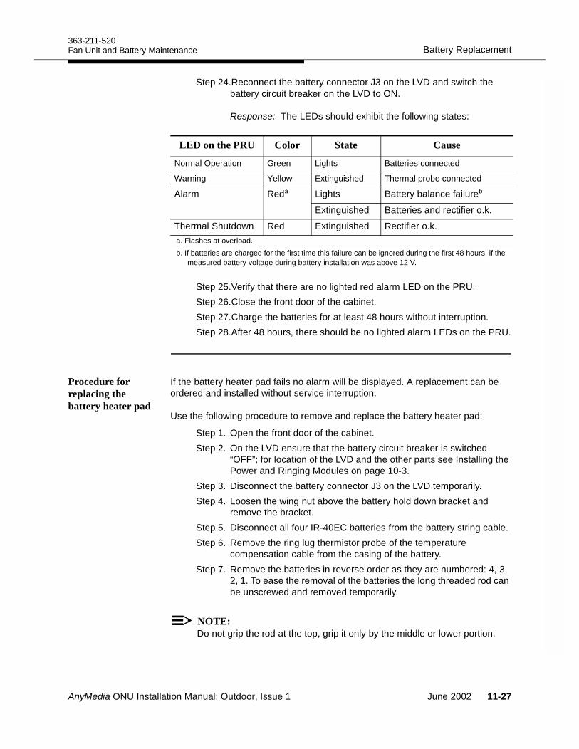
363-211-520Battery ReplacementFan Unit and Battery Maintenance
Step 24.Reconnect the battery connector J3 on the LVD and switch the battery circuit breaker on the LVD to ON.
Response: The LEDs should exhibit the following states:
Step 25.Verify that there are no lighted red alarm LED on the PRU.Step 26.Close the front door of the cabinet. Step 27.Charge the batteries for at least 48 hours without interruption.Step 28.After 48 hours, there should be no lighted alarm LEDs on the PRU.
Procedure for replacing the battery heater pad
If the battery heater pad fails no alarm will be displayed. A replacement can be ordered and installed without service interruption.
Use the following procedure to remove and replace the battery heater pad:
Step 1. Open the front door of the cabinet.Step 2. On the LVD ensure that the battery circuit breaker is switched
“OFF”; for location of the LVD and the other parts see Installing the Power and Ringing Modules on page 10-3.
Step 3. Disconnect the battery connector J3 on the LVD temporarily.Step 4. Loosen the wing nut above the battery hold down bracket and
remove the bracket.Step 5. Disconnect all four IR-40EC batteries from the battery string cable.Step 6. Remove the ring lug thermistor probe of the temperature
compensation cable from the casing of the battery.Step 7. Remove the batteries in reverse order as they are numbered: 4, 3,
2, 1. To ease the removal of the batteries the long threaded rod can be unscrewed and removed temporarily.
NOTE:Do not grip the rod at the top, grip it only by the middle or lower portion.
LED on the PRU Color State Cause
Normal Operation Green Lights Batteries connected
Warning Yellow Extinguished Thermal probe connected
Alarm Reda Lights Battery balance failureb
Extinguished Batteries and rectifier o.k.
Thermal Shutdown Red Extinguished Rectifier o.k.a. Flashes at overload.b. If batteries are charged for the first time this failure can be ignored during the first 48 hours, if the
measured battery voltage during battery installation was above 12 V.
AnyMedia ONU Installation Manual: Outdoor, Issue 1 June 2002 11-27
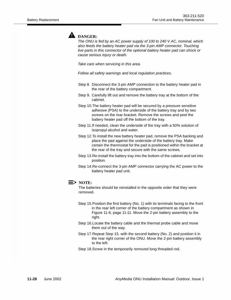
Battery Replacement363-211-520
Fan Unit and Battery Maintenance
DANGER:The ONU is fed by an AC power supply of 100 to 240 V AC, nominal, which also feeds the battery heater pad via the 3-pin AMP connector. Touching live parts in this connector of the optional battery heater pad can shock or cause serious injury or death.
Take care when servicing in this area.
Follow all safety warnings and local regulation practices.
Step 8. Disconnect the 3-pin AMP connection to the battery heater pad in the rear of the battery compartment.
Step 9. Carefully lift out and remove the battery tray at the bottom of the cabinet.
Step 10.The battery heater pad will be secured by a pressure sensitive adhesive (PSA) to the underside of the battery tray and by two screws on the rear bracket. Remove the screws and peel the battery heater pad off the bottom of the tray.
Step 11.If needed, clean the underside of the tray with a 50% solution of isopropyl alcohol and water.
Step 12.To install the new battery heater pad, remove the PSA backing and place the pad against the underside of the battery tray. Make certain the thermostat for the pad is positioned within the bracket at the rear of the tray and secure with the same screws.
Step 13.Re-install the battery tray into the bottom of the cabinet and set into position.
Step 14.Re-connect the 3-pin AMP connector carrying the AC power to the battery heater pad unit.
NOTE:The batteries should be reinstalled in the opposite order that they were removed.
Step 15.Position the first battery (No. 1) with its terminals facing to the front in the rear left corner of the battery compartment as shown in Figure 11-6, page 11-11. Move the 2-pin battery assembly to the right.
Step 16.Locate the battery cable and the thermal probe cable and move them out of the way.
Step 17.Repeat Step 15. with the second battery (No. 2) and position it in the rear right corner of the ONU. Move the 2-pin battery assembly to the left.
Step 18.Screw in the temporarily removed long threaded rod.
11-28 June 2002 AnyMedia ONU Installation Manual: Outdoor, Issue 1
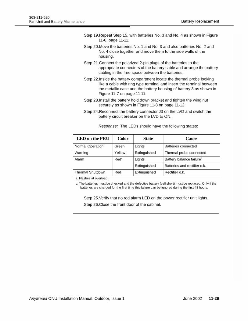
363-211-520Battery ReplacementFan Unit and Battery Maintenance
Step 19.Repeat Step 15. with batteries No. 3 and No. 4 as shown in Figure 11-6, page 11-11.
Step 20.Move the batteries No. 1 and No. 3 and also batteries No. 2 and No. 4 close together and move them to the side walls of the housing.
Step 21.Connect the polarized 2-pin plugs of the batteries to the appropriate connectors of the battery cable and arrange the battery cabling in the free space between the batteries.
Step 22.Inside the battery compartment locate the thermal probe looking like a cable with ring type terminal and insert the terminal between the metallic case and the battery housing of battery 3 as shown in Figure 11-7 on page 11-11.
Step 23.Install the battery hold down bracket and tighten the wing nut securely as shown in Figure 11-8 on page 11-12.
Step 24.Reconnect the battery connector J3 on the LVD and switch the battery circuit breaker on the LVD to ON.
Response: The LEDs should have the following states:
Step 25.Verify that no red alarm LED on the power rectifier unit lights.Step 26.Close the front door of the cabinet.
LED on the PRU Color State Cause
Normal Operation Green Lights Batteries connected
Warning Yellow Extinguished Thermal probe connected
Alarm Reda Lights Battery balance failureb
Extinguished Batteries and rectifier o.k.
Thermal Shutdown Red Extinguished Rectifier o.k.a. Flashes at overload.b. The batteries must be checked and the defective battery (cell short) must be replaced. Only if the
batteries are charged for the first time this failure can be ignored during the first 48 hours.
AnyMedia ONU Installation Manual: Outdoor, Issue 1 June 2002 11-29

Battery Replacement363-211-520
Fan Unit and Battery Maintenance
11-30 June 2002 AnyMedia ONU Installation Manual: Outdoor, Issue 1
AnyMedia ONU Installation Manual: Outdoor, Issue 1
Installation and Maintenance Record AInstallation and Maintenance Record 1
The following two pages are copies for the Installation and Maintenance Record from the Product Manual IR Series Batteries (Issue 7, Comcode 107078859).
June 2002 A-1
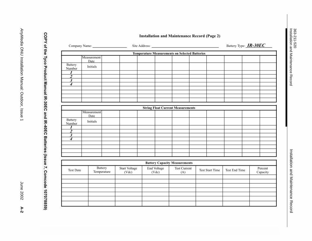
AnyMedia O
NU
Installation Manual: O
utdoor, Issue 1June 2002
A-2
363-211-520Installation and M
aintenance Record
Installation and Maintenance R
ecord
!
0<(
+93
9 %
1#0+%
1#0.
&)%&
&9,=0
+1,1,22 >-
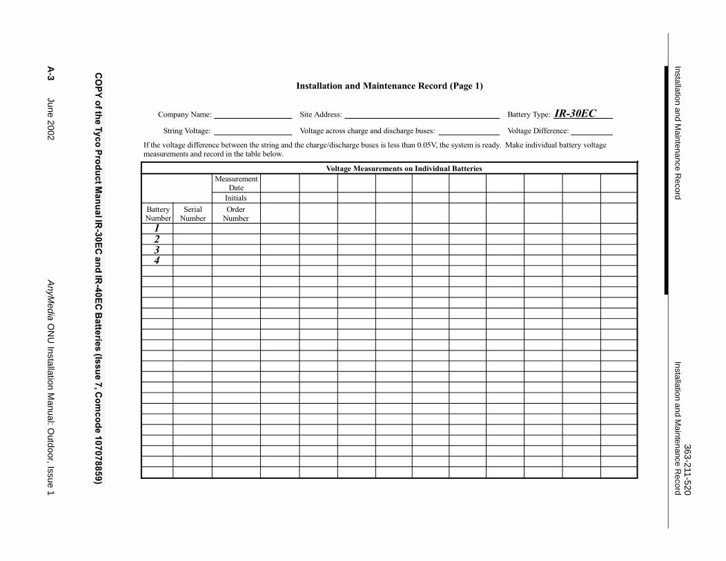
A-3
June 2002AnyM
edia ON
U Installation M
anual: Outdoor, Issue 1
Installation and Maintenance R
ecord363-211-520
Installation and Maintenance R
ecord
*# #
""
!!
" !#""$ !!!%! !&'&()! '
!$'
0<(
+93
9 %
1#0+%
1#0.
&)%&
&9,=0
+1,1,22 >-
363-211-520Installation and Maintenance RecordInstallation and Maintenance Record
AnyMedia ONU Installation Manual: Outdoor, Issue 1 June 2002 A-4
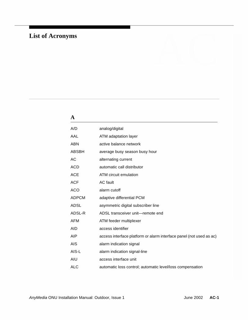
AnyMedia ONU Installation Manual: Outdoor, Issue 1
AC
List of AcronymsA
A/D analog/digital
AAL ATM adaptation layer
ABN active balance network
ABSBH average busy season busy hour
AC alternating current
ACD automatic call distributor
ACE ATM circuit emulation
ACF AC fault
ACO alarm cutoff
ADPCM adaptive differential PCM
ADSL asymmetric digital subscriber line
ADSL-R ADSL transceiver unit—remote end
AFM ATM feeder multiplexer
AID access identifier
AIP access interface platform or alarm interface panel (not used as ac)
AIS alarm indication signal
AIS-L alarm indication signal-line
AIU access interface unit
ALC automatic loss control; automatic level/loss compensation
June 2002 AC-1
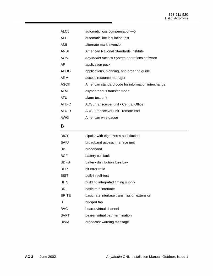
363-211-520List of Acronyms
ALC5 automatic loss compensation—5
ALIT automatic line insulation test
AMI alternate mark inversion
ANSI American National Standards Institute
AOS AnyMedia Access System operations software
AP application pack
APOG applications, planning, and ordering guide
ARM access resource manager
ASCII American standard code for information interchange
ATM asynchronous transfer mode
ATU alarm test unit
ATU-C ADSL transceiver unit - Central Office
ATU-R ADSL transceiver unit - remote end
AWG American wire gauge
B
B8ZS bipolar with eight zeros substitution
BAIU broadband access interface unit
BB broadband
BCF battery cell fault
BDFB battery distribution fuse bay
BER bit error ratio
BIST built-in self-test
BITS building integrated timing supply
BRI basic rate interface
BRITE basic rate interface transmission extension
BT bridged tap
BVC bearer virtual channel
BVPT bearer virtual path termination
BWM broadcast warning message
AC-2 June 2002 AnyMedia ONU Installation Manual: Outdoor, Issue 1
363-211-520List of Acronyms
C
C/N carrier-to-noise ratio
CAC connection admission control
CALRS centralized automatic loop reporting system
CASTL customer advocate system test lab
CBR constant bit rate
CC clear channel
CCITT international telephone and telegraph consultative committee
CCN customer change notice
CCS hundred call seconds
CD-ROM compact disk - read only memory
CDV cell delay variation
CDVT cell delay variation tolerance
CES circuit emulation service
CES-IWF circuit emulation service interworking function
CEV controlled environment vault
CF current feed
CHAN/MON channel testing and monitoring (switch side)
CIT craft interface terminal
CL center line
CLF carrier line failure
CLP cell loss priority
CMI control mode idle
CMIS common management information service
CN change notice
CO central office
COACH customized online aid for customer help
COMDAC common data and control
COPM customer operations and program management
CORRCNT corrected HEC error counter
COT central office terminal
AnyMedia ONU Installation Manual: Outdoor, Issue 1 June 2002 AC-3
363-211-520List of Acronyms
CPE customer premises equipment
CPFT customer premises facility terminal
CPI calling party identification
CPS cabinet power system
CR critical
CRC cyclic redundancy check
CRV call reference value
CS current sink
CSA carrier serving area
CSMD/CD carrier sense multiple access/collision detection
CSS controlled slip seconds
CSS-P controlled slip seconds-path
CSU channel service unit
CTS customer technical support
CTU craft test unit
CU channel unit
CV coding violation
CV-L coding violation-line
CV-LFE coding violations-line - far end
CV-P coding violation-path
CV-S coding violations-section
CVC control virtual channel
CVPT control virtual path termination
D
DACS digital access cross-connect system
dB decibel
dBm decibel referenced to one milliwatt
DC direct current
DCD received line signal detector
DCE data communication equipment
DCLU digital carrier line unit
AC-4 June 2002 AnyMedia ONU Installation Manual: Outdoor, Issue 1
363-211-520List of Acronyms
DCN data communication network
DCS digital cross-connect system
DCTP direct current test pair
DDL delivered data link
DDM digital data multiplexer
DDS digital data services
DFI digital facilities interface
DHCP dynamic host configuration protocol
DID direct inward dialing
DIP dual in-line package
DLC digital loop carrier
DLCI data link connection identifier
DM degraded minute
DMT discrete multitone
DMU digital measurement unit
DNIS dialed number identification service
DNS domain name service
DNUS digital network unit–subscriber
DOD direct outward dialing
DP data port or dial pulse
DPFU dual power feed unit
DPO dial pulse originate
DPT dial pulse terminate
DRAM dynamic random access memory
DS0 digital signal, level 0
DS1 digital signal, level 1
DS3 digital signal, level 3
DSL digital subscriber line
DSP digital signal processor
DSR DCE ready
DSU data service unit
AnyMedia ONU Installation Manual: Outdoor, Issue 1 June 2002 AC-5
363-211-520List of Acronyms
DSX digital signal cross-connect
DSX-1 digital signal cross-connect, level 1
DSX-3 digital signal cross-connect, level 3
DTC digital trunk controller
DTE data terminal equipment
DTMF dual tone multifrequency
DU data unit
DX duplex
E
EBS enhanced business service
EC error correction
ECI equipment catalog item
E&M ear and mouth
EM element manager
EMC electromagnetic compatibility
EMF electromotive force
EMI electromagnetic interference
EMS element management system
EOC embedded operations channel
EPD echo path delay
ERL echo return loss
ES errored seconds
ES-L errored second-line
ESD electrostatic discharge
ESF extended superframe
ES-L errored seconds-line
ES-LFE errored seconds-line far end
ES-P errored seconds-path
ES-S errored seconds - section
ETO equalized transmission only
AC-6 June 2002 AnyMedia ONU Installation Manual: Outdoor, Issue 1
363-211-520List of Acronyms
F
4TDM four-wire tandem
FC failure count
FC-L failure counts-line
FC-LFE failure counts-line - far end
FCC Federal Communications Commission
FCM fuse circuit module
FDI feeder distribution interface
FE far end
FEAC far end alarm and control
FELP far end loopback
FITL fiber in the loop
FITs failure in 109 hours
fpm flashes per minute
FPT framed path termination
FSA first site application
FSAN full service access network
FTP file transfer protocol
FX foreign exchange
FXO foreign exchange office
FXS foreign exchange station
FRMGND frameground
G
GA general availability
GCRA generic cell rate algorithm
GOS grade of service
GPB general purpose bus
GPC general purpose communications
GR-303 Telcordia Technologies, Inc. Standard GR-303
GSFN generic signaling function
AnyMedia ONU Installation Manual: Outdoor, Issue 1 June 2002 AC-7
363-211-520List of Acronyms
GSI graphical system interface
GTL Gunning transceiver logic
GTSIP global technical support information platform
H
HBER high BER
HCS header check sequence
HDBH high day busy hour
HDLC high-level data link control
HDSL high bit rate digital subscriber line
HDSL2 high bit rate digital subscriber line-second generation
HDT host digital terminal
HEC header error code
HTTP hypertext transfer protocol
Hz hertz
I
I/O input/output
IAD integrated access device
IAT integrated access terminal
IATSI IAT system interface
IBERT integrated bit error test
ICLE initial customer laboratory evaluation
ICP IMA control protocol
ID identifier
IDCU integrated digital carrier unit
IDLC integrated digital loop carrier
IDT integrated digital terminal
IEEE Institute of Electrical and Electronics Engineers
IETF Internet Engineering Task Force
IMA inverse multiplexing for ATM
IMLT integrated mechanized loop testing
AC-8 June 2002 AnyMedia ONU Installation Manual: Outdoor, Issue 1
363-211-520List of Acronyms
INA integrated network access
INIT initialization/diagnostic
IP Internet protocol
IPX Internet packet exchange
IS in service
ISDL integrated subscriber digital line
ISDN integrated services digital network
ISO international organization for standards
ISP Internet service providers
ITU International Telecommunications Union
IV ICP cell violation
IV-IMA IPC violations (count of errored, invalid or missing IPC cells)
IXC interexchange carrier
K
kbps kilobits per second
kBps kilobytes per second
kHz kilohertz
kW kilowatt
L
LAN local area network
LAPD link access protocol D-channel
LBO lightguide build out
LCD loss of cell delineation
LDS local digital switch
LED light-emitting diode
LFACS loop facilities assignment and control system
LFP logical feeder port
LLN logical line number
LMI local management interface
LOCD loss of cell delineation
AnyMedia ONU Installation Manual: Outdoor, Issue 1 June 2002 AC-9
363-211-520List of Acronyms
LOF (lof) loss of frame
LOFA loss of frame alignment
LOP loss of pointer
LOS (los) loss of signal
LOST loss of signal timeout
LSAS line side answer supervision
LTD local test desk
LTF loop test frame
LTS loop test system
LULT line unit network termination
LUNT line unit network termination
LVD low voltage disconnect
M
mA milliampere
MAT Metropolitan Area T-carrier
Mbps megabits per second
MBps Megabytes per second
MBS maximum burst size
MDF main distributing frame
MDS2 metallic distribution shelf 2
MDSU metallic distribution server unit
MEA mismatch of equipment and attributes
MHz mega hertz
MIB management information base
MJ major
MLTS multiline telecommunications system
MMSU modular metallic service unit
MN minor
MR modification request
ms millisecond
MSC metallic shelf controller
AC-10 June 2002 AnyMedia ONU Installation Manual: Outdoor, Issue 1
363-211-520List of Acronyms
MSG message switch
MTBF mean time between failures
MTU maximum transfer unit
MVEC majority vote error correction
N
NB narrowband
NCTE network channel terminating equipment
NE near end or network element
NEBS network equipment building systems
NEC national electric code
NI network interface
NIC network interface card
NMP network management protocol
NMS network management station
nrt-VBR nonreal time variable bit rate
NSA nonservice affecting
NT 1 network termination - 1
NTP network time protocol
NTT no test trunk
NTR network timing reference
NVDS nonvolatile data storage
NVPS nonvolatile program storage
O
OAM&P operations, administration, maintenance, and provisioning
OAP optical application pack
OC optical carrier
OCD out of cell
OCP optical controller pack
OCU office channel unit
OE originating equipment
AnyMedia ONU Installation Manual: Outdoor, Issue 1 June 2002 AC-11
363-211-520List of Acronyms
OHT on-hook transmission
OLIU optical line interface unit
ONU optical network unit
OOS out of service
OPS/INE operations system for intelligent network
OS operations system
OSMINE operations systems modification of intelligent network elements
OSP outside plant
OTGR operations technology generic requirements
P
P-AIS path alarm indication signal
P/AR peak to average ratio
PAM pulse amplitude modulation
PBX private branch exchange
PC personal computer
PCI peripheral component interconnect
PCM pulse code modulation
PCR peak cell rate
PDF portable document format
PDU protocol data unit
PFP physical feeder port
PGTC pair gain test controller
PIDB processor interface data bus
PLAR private line automatic ring
PLCP physical layer convergence protocol
PLN physical line number
PLR pulse line repeater
POTS plain old telephone service
ppm parts per million
PPP point to point protocol
PRC-Access Product Realization Center-Access
AC-12 June 2002 AnyMedia ONU Installation Manual: Outdoor, Issue 1
363-211-520List of Acronyms
PRF power rectifier fault
PRI primary rate interface
PRS primary reference source
PRU power rectifier unit
PSAP public safety answering point
PSC protection switching counts
PSD power spectral density
PSDM power spectral density mask
PSES p-bit severely errored seconds
PSTN public switched telecommunications network
PTU power and test unit
PVC permanent virtual circuit
PVP permanent virtual path
Q
QMON quality monitoring
QoS quality of service
R
RACO remote alarm cutoff
RADSL rate adaptive digital subscriber line
RAI remote alarm indication
RAM random access memory
RCLK receive clock
RC/V recent change/verify
RD ring down
RDI remote defect indication
REFCLK reference clock
REN ringing equivalence number
RFI remote failure indication
RGU ringing generator unit
RIP routing information protocol
AnyMedia ONU Installation Manual: Outdoor, Issue 1 June 2002 AC-13
363-211-520List of Acronyms
RMC remote maintenance connection
RMU remote measurement unit
ROC remote operations channel
R-S Reed-Solomon
RSF receive signal failed
RT remote terminal
rt-VBR real time variable bit rate
RTAC regional technical assistance center
RTLP receive transmission level point
RTU remote test unit
Rx-UUS-IMA receive unusable seconds-IMA
S
SA service affecting
SARTS Switched Access Remote Test System
SAS-P severely errored framing/alarm indication signal seconds-path
SCEC second channel error correction
SCR sustained cell rate
SDSL symmetric digital subscriber line
SEFS severely errored framing seconds
SEFS-P severely errored framing seconds-path
SEFS-S severely errored framing seconds-section
SES severely errored seconds
SES-P severely errored second-path
SES-S severely errored seconds-section
SES-IMA severely errored seconds-IMA
SES-L severely errored seconds-line
SES-LFE severely errored seconds-line far end
SES-P severely errored seconds-path
SES-S severely errored seconds-seconds
SF superframe
SHDSL single-pair high speed digital subscriber line
AC-14 June 2002 AnyMedia ONU Installation Manual: Outdoor, Issue 1
363-211-520List of Acronyms
shelf_PCR shelf peak cell rate
SID source identifier
SL selecting slope
SNMP simple network management protocol
SNR signal to noise ratio
SONET synchronous optical network
SWDL software download
T
TAP test access path
TAP100 test application pack
TBCU test bus control unit
TC TAP connected
TCA threshold crossing alert
TCP/IP transmission control protocol/Internet protocol
TDM time division multiplexing
TDR time domain reflectometry
TL1 transaction language -1
TL1SI TL1 system interface
TLP transmission level point or test level point
TMC timeslot management channel
TMS transmission (test) measuring set
TO transmission only
TOS test operations system
TR technical reference
TR-08 Telcordia Technologies, Inc. Standard TR-008
TSA timeslot assignment
TSC test system controller
TSG timing signal generator
TSI time slot interchange
TTF transmission test facility
AnyMedia ONU Installation Manual: Outdoor, Issue 1 June 2002 AC-15
363-211-520List of Acronyms
TTLP transmit transmission level point
Tx-UUS-IMA transmit unusable seconds-IMA
U
UART universal asynchronous receiver/transmitter
UAS unavailable seconds
UAS-IMA unavailable seconds-IMA
UAS-L unavailable seconds-line
UAS-LFE unavailable seconds-line far end
UAS-P unavailable seconds-path
UBR unspecified bit rate
UCC universal communication channel
UDP user datagram protocol
UDT unstructured data transfer
U-DSL U-interface digital subscriber line
UIP user interface panel
UNCCNT uncorrected HEC error counter
UNI user network interface
UPC usage parameter control
USB universal serial bus
UPN urgent problem notification
UVG universal voice grade
V
VB virtual bank
VBR variable bit rate
VC virtual circuit (traditional DLC services) or virtual channel (ATM xDSL services)
VCC virtual channel connection
VCI virtual channel identifier
VCOT virtual central office terminal
VDC volts direct current
AC-16 June 2002 AnyMedia ONU Installation Manual: Outdoor, Issue 1
363-211-520List of Acronyms
VDSL very high speed digital subscriber line
VF voice frequency
VFDE voice frequency data enhancement
VGA video graphics array
VoDSL voice over digital subscriber line
VOM volt ohm meter
VP virtual path
VPC virtual path connection
VPI virtual path identifier
VPN virtual private network
VPT virtual path termination
VRLA valve-regulated lead-acid
Vrms volts root mean square
VRT virtual remote terminal
VT virtual tributary
W
WAN wide area network
WATS wide area telephone service
WL working length
WRR weighted round robin
X
XTC extended test controller
Z
ZBS zero byte substitution
ZCS zero code suppression
AnyMedia ONU Installation Manual: Outdoor, Issue 1 June 2002 AC-17

363-211-520List of Acronyms
AC-18 June 2002 AnyMedia ONU Installation Manual: Outdoor, Issue 1
AnyMedia ONU Installation Manual: Outdoor, Issue 1
GL3
GlossaryNumerics
10BaseT IEEE 802.3 standard for Ethernet transmission over unshielded twisted pair.
A
Access interface platform
A family of equipment that provides cost-effective and flexible ac-cess for different services; e.g., voice and data, using a common platform.
ACE COMDAC An ATM COMDAC which implements circuit emulation service (CES) for the DS1 links to the backbone network using unstructured data transfer mode (UDT).
Admissible bandwidth The amount of bandwidth allocated to a service category in the up-stream and downstream directions (not applicable to UBR). The sum of the effective bandwidths allocated to a ll connections sup-ported by a service category, divided by the overbooking factor of that service category, must no exceed the admissible bandwidth of this service category. The admissible bandwidth of a service cate-gory may not exceed the shelf PCR.
ADSL-lite A version of asymmetric digital subscriber line (ADSL) that is less expensive than full-rate ADSL and that operates at a lower bit rate than full-rate ADSL. This version of ADSL is specified in ITU-T G.992.2.
AFMO logical feeder port
An entity used to address a SONET path or a protection group.The logical feeder port concept allows addressing of attributes or enti-ties that are common to all physical feeder ports associated with the logical feeder port and that are independent of simplex or duplex mode. The AFMO and the AFMDS3 have two logical feeder ports.
June 2002 GL-1
363-211-520Glossary
AFMO physical feeder port
Corresponds to the physical termination of the optical feeder. The physical feeder port concept allows the addressing of SONET phys-ical medium, selection, and line layer entities. An AnyMedia shelf has two physical feeder ports when using one AFMO in simplex mode and four physical feeder ports when using two AFMOs in du-plex mode.
AnyMedia operations gateway
Operations access for up to 20 RTs via universal communication channels (UCCs).
Application layer (OSI) A layer of OSIRM. Provides the management of communications between user applications. Examples include e-mail and file trans-fer.
Asymmetric digital subscriber line (ADSL)
A method of data transmission over unloaded copper loops. The data rate transmitted toward the end user is typically much higher (e.g., 6 Mbps) than the data rate transmitted by the end user (e.g., 640 Kbps).
Asynchronous transfer mode (ATM)
A high-speed connection-oriented mulitplexing and switching method that utilizes fixed-length cells to support multiple types of traffic. Transmission is synchronized at the start and end of each character, allowing different types of services to be carried over one system.
ATM adaptation layer (AAL)
A set of internationally standardized protocols and formats that de-fine support for circuit emulation, packet video and audio, and con-nection-oriented and connectionless data services. There are four standard protocols defined for AAL—AAL1, AAL2, AAL3/4, and AAL5.
AAL5 is used for bursty LAN traffic and uses the conventional five-byte ATM header. AAL5 does not support cell multiplexing.
ATM feeder The connection from the AFM to the ATM transport network. This connection may be either DS3, DS1, or OC-3c. The ATM feeder may connect directly to an ATM switch or access concentrator de-vice. In addition, the connection between the AFM and the switch or access concentrator may incorporate a multiplexer. In daisy-chained configurations, the ATM feeder for each AFM, except the one closest to the switch or access concentrator, connects to the previous AFM in the chain. This connection may be direct or through a multiplexer. Note that daisy-chaining is available only with DS3 and OC-3c AFMs.
ATM-RSF on ADSL line Ten consecutive seconds with each second having one or more of the following anomalies:
At least 18 ADSL superframes with ATM HEC anomalies
At least one ADSL superframe with ATM cell delineation anomalies.
GL-2 June 2002 AnyMedia ONU Installation Manual: Outdoor, Issue 1
363-211-520Glossary
ATM technology Asynchronous transfer mode is a data communications format in which transmission is synchronized at the start and end of each character, allowing different types of services to be carried over one system.
ATM traffic statistics For the AnyMedia Access System, ATM traffic statistics refers to the performance monitoring function for ATM cell counts. ATM traffic statistics can be collected either at the shelf level, or for specific connections. At the connection level, the technician may choose to activate ATM traffic statistics for all connections on an AP, for all connections on an end-user port, or for an individual connection.
ATM xDSL subsystem The AnyMedia Access System components that are needed to pro-vide ATM xDSL services, i.e., the AFM, OAP, OCP, ADSL AP, SDSL AP and SHDSL AP. Note that the OAP and OCP can carry both ATM xDSL and traditional DLC traffic and are included in both the ATM xDSL and traditional DLC subsystems. Components that only carry traditional DLC services (e.g., the TDM COMDAC) are not in-cluded in the ATM xDSL subsystem. The ACE COMDAC is a com-ponent of both the traditional DLC and ATM xDSL subsystems.
Attenuation of ADSL line
The difference in dB between the power received at the far end and the power transmitted by the near end.
Authentication Process used to verify that only those users or operating systems authorized to access the system are permitted to do so and to en-sure that the user or operating system is only allowed to alter or ex-tract its authorized data.
Auto discovery Automatically updates and maintains an inventory of the AnyMedia FAST shelf.
Autonomous reports Messages sent by the AnyMedia Access System to operations sys-tems or element managers (EMs) to report conditions such as er-rors, faults, and threshold crossings. The AnyMedia Access Sys-tem’s processors decide when or what messages are sent; they are not externally requested.
B
Basic rate interface (BRI)
An ISDN access interface type made up of two B channels, each at 64 kbps, and one D channel at 16 kbps (2B+D).
B channel An ISDN bearer service channel that can carry either voice or data at a speed of 64 kbps.
Bit error ratio The quality of transmission is measured in the number of errored bits per number of bits received.
Broadband services High speed data and asynchronous transfer mode services.
AnyMedia ONU Installation Manual: Outdoor, Issue 1 June 2002 GL-3
363-211-520Glossary
C
Cell A fixed-length 53-octet packet used in ATM. The AM cell has a 5-octet header and a 48-octet payload.
Cell delay variation (CDV)
The amount of difference between a cell’s expected arrival time and its actual arrival time. Also called “jitter”.
Cell delay variation tolerance (CDVT)
A parameter which, in CBR transmissions, determines the level of jitter (i.e., cell delay variation). The upper bound on the jitter mea-surement is the CDVT.
Cell header A 5-octet header that defines control information used in process-ing, multiplexing, and switching cells.
Cell loss priority A field in the ATM cell header showing two levels of priority for ATM cells. CLP=0 cells are a higher priority than CLP=1 cells and may be discarded if there is a congestion to preserve the cell loss ratio of CLP=0 cells.
Cell loss ratio (CLR) The value the network agrees to offer as an objective over the life-time of the connection. This value is specified per service class at the turn-up.
Cell transfer delay (CTD)
The transit delay of an ATM cell successfully passed between two designated boundaries on the AnyMedia Access System, when the system is loaded conservatively.
Cells received The total number of cells that the shelf received from the CPE.
Channel The electronics portion of a digital loop carrier line; typically from the tip/ring output of the channel unit or application pack toward the central office. Includes up to the switch interface if integrated DLC. Includes the transmit and receive DS0s, codecs, and hybrids.
Circuit emulation service (CES)
An ATM configuration that allows the ATM network to act as a trans-parent transport pipe for constant bit-rate circuits.
CES interworking function (CES-IWF)
That part of a CES system that interfaces the signal to be emulated, converting such signals to ATM format in the transmit direction and converting ATM signals to the original format in the receive direc-tion.
Circuit pack protection The capability for a given pack to relinquish its functionality to an-other instance of the same circuit pack. The circuit pack that pro-vides system functionality is called the active pack, while the circuit pack that protects the active pack is called the standby pack. When a switch occurs, the roles of the active and standby circuit packs are reversed. A switch occurs, for example, when the active pack fails or when an administrator issues an OAM&P command.
GL-4 June 2002 AnyMedia ONU Installation Manual: Outdoor, Issue 1
363-211-520Glossary
ClearReach feature The ClearReach feature for the ConnectReach and ConnectReach Plus terminals that improves modem performance. The ClearReach feature requires voice frequency data enhancement (VFDE) in the AnyMedia FAST shelf.
Collocation Grouping entities in the same physical location.
Common unit A unit, or application pack, that performs the main bandwidth man-agement and control for the AnyMedia FAST shelf.
Competitive access The ability for nonincumbent carriers to provide local access.
Configuration management
Consists of a set of functions to exercise control over elements in the network, including initialization, parameter setting, starting and stopping, and collection of information about the configuration.
Connection admission control (CAC)
CAC is a set of actions taken by the network during the call set-up phase to determine whether a connection request can be accepted, should be rejected, or may be re-allocated based on QoS defini-tions.
COSET The header error co-setting (55 hex by ATM standards) is used to maintain a value other than zero in the header error code (HEC) field. If the first four bytes in the header are zero, the HEC derived from these bytes is also zero. When this occurs and there are a string of zeros in the data, the receiver cannot determine the cell boundaries. Therefore, it is recommended that the value 55 hex be added to the HEC before transmission.
Craft interface terminal (CIT) port
The port on the craft test unit (CTU) where the graphical system in-terface (GSI) or a TL1 system interface (TL1SI) is connected.
Customer premises equipment (CPE)
Equipment that resides and is operated at a customer site.
Cyclic redundancy check (CRC)
An algorithm that detects bit errors causes in data transmission.
D
D4 A framing and synchronization format for T1 transmission facilities.
Dangler cable Cable that effectively brings a backplane connector to the front of the shelf.
Database evolution When AFM software is upgraded to provide new features, it is usu-ally necessary to adapt or extend the database structure to accom-modate these features. This is done automatically as part of soft-ware activation and is termed database evolution.
Data communications (or circuit termination) equipment (DCE)
A modem or network communications interface device.
AnyMedia ONU Installation Manual: Outdoor, Issue 1 June 2002 GL-5
363-211-520Glossary
Data terminal equipment (DTE)
Data processing equipment that interfaces to the communications network (DCE).
DC alarm services Point-to-point metallic services that connect subscriber premises with fire, police, or security services’ monitoring locations. These services are delivered by the MDS2 shelf using DC circuit-emula-tion technology provided by MCU CUs from Tollgrade Communica-tions, Inc.
D channel The ISDN out-of-band (16 kbps in BRI) signaling channel that car-ries the ISDN user signals or can be used to carry packet-mode data.
Degrowth The removal of circuit packs or traffic from a system via a provision-ing operation (may be accompanied by the physical removal of as-sociated equipment, but this is not required).
Digital bypass pair A pair of MDS2 CUs (such as the Tollgrade MCU-5405 CUs) that provide the equivalent of a metallic bypass pair without requiring a physical copper pair.
Digital data services Digital data services refer to 64 kbps clear channel digital service provided between the customer and the CO.
Digital signal 0 (DS0) One 56-kbps framed channel out of the 24 contained in a DS1 channel.
Digital signal 1 (DS1) The North American standard 1.544-Mbps digital channel.
Digital signal 3 (DS3) The North American standard 44.736-Mbps digital channel.
Discarded cells Cells that are dropped to avoid exceeding a particular connection’s traffic contract.
Distribution cable The cable from the field side of an FDI to the customer's ready ac-cess case or distribution box, but not including the drop (formal def-inition) or inside wiring.
Downstream direction Transmission direction from ATM data network or telephony switch to customer.
Downstream VP In a daisy chain, a VP that terminates on a shelf that is farther away from the ATM transport network than the shelf being addressed. “Downstream” here does not refer to the direction of transmission.
Drop Formal definition is the short cable from an aerial ready access case or buried plant distribution box to the customer's house, not in-cluding inside wiring. Informally used, especially when describing test configurations like "splitting access,” to be equal to line or loop. In this latter informal case (loop), it is all the copper cable to and in-cluding the telephone set.
Dropped cells The number of cells that are dropped as a result of exceeding either a particular connection’s traffic contract or the total allowable band-width of the shelf.
GL-6 June 2002 AnyMedia ONU Installation Manual: Outdoor, Issue 1
363-211-520Glossary
DS1 framing format The prescribed recurring pattern of bits transmitted that enables the receiver to identify the start of a frame and the frame number in a sequence of frames. The system supports two different DS1 frame formats, extended superframe (ESF), or superframe (SF).
DS1 link The general term DS1 link can denote a physical DS1 link when us-ing a TDM COMDAC, or a circuit emulated link when using an ACE COMDAC.
DS1 logical feeder port These ports are associated with the VRT structure of the AnyMedia Access System. The VRT structure allows the flexible assignment of APs and CUs to VRTs that are associated with specific functional needs of partitioning the AnyMedia Access System. Three forms of VRTs are allowed: GR-303 (up to 3 allowed), TR-08 (up to 20 al-lowed), and INA (up to 20 allowed). The total number of VRTs and the DS1 content of each VRT are limited by the total number of DS1 physical feeder ports. Any DS1 physical feeder port can be associ-ated with any DS1 logical feeder port.
DS1 physical feeder port
These ports provide two twisted pair transmit/receive DS1 inter-faces to the AnyMedia Access System. Up to 20 DS1 physical feeder ports are available and are physically identified through the AID with the DS1 (shelf number), pack number (1 to 5), and the port number (1 to 4).
Dying gasp A message the ATU-R transmits to the ATU-C when its electrical power is being shut off. The message indicates to a service techni-cian or an administrator that an interruption on an ADSL line was caused by a power interruption at the ATU-R and not caused by a transmission failure or an AnyMedia FAST shelf failure.
E
Early packet discard The early packet discard function ensures that the ATM equipment discards entire AAL5 packets during periods of congestion. This is especially important when a relatively large number of Transmis-sion Control Protocol (TCP) sources contend for a particular bottle-neck.
Effective bandwidth A measure of the amount of bandwidth a connection uses. For CBR connections, it equals PCR. For VBR connections, it is a function of PCR, SCR, MBS, and CLR. For VBR connections, this measure is defined differently for different congestion points on the same con-nection. The CAC algorithm uses this measure at potential conges-tion points when determining whether to admit a new connection.
Errored cells Cells having an invalid header field after HEC procedures are com-pleted.
AnyMedia ONU Installation Manual: Outdoor, Issue 1 June 2002 GL-7
363-211-520Glossary
Errored cells received The number of cells that the shelf received from the CPE with de-tected errors.
ES on upstream SDSL line
The corrected HEC error counter (CORRCNT) and the uncorrected HEC error counter (UNCCNT) event counter data are accumulated and mapped to ES. The total count in one second is the number of ESs. The HEC error counter data is accumulated, and the ES counts are reported on a 15-minute and 1-day basis. The COR-RCNT counter tracks the number of corrected HEC errors. The UN-CCNT counter tracks the number of uncorrected HEC errors.
Ethernet A LAN that uses the CSAM/CD media access method and operates at 10 Mbps, usually over coax medium.
F
Facility protection The capability for a system to choose which signal from two facili-ties to pass along to the internal, unprotected transmission paths. A system switches from one facility to the other, for example, when the facility being used fails or when an administrator issues an OAM&P command.
Fault management Consists of a set of functions, such as testing, that enable the de-tection, isolation, and correction of abnormal operation of the tele-communications network and its environment.
Feeder cable The portion of a customer loop from the central office switch (inte-grated), or from the main distribution frame (MDF) to the office side of the feeder/distribution interface (FDI). In the case of DLC it in-cludes the DLC line plus any copper cable from the RT to the FDI.
Fixed wireless network A digital loop carrier (DLC) system that uses wireless (radio) trans-mission through the air as the distribution medium to the home, re-placing the traditional copper wire outside plant. A radio unit is mounted on the outside of the home (network interface unit) and is connected to standard twisted pair wiring within the home.
FLASH memory device A nonvolatile memory device that may be reprogrammed in the field through software download.
Framed path termination
The physical framer device on the ACE COMDAC which terminates a DS1 signal delivered by a CES-IWF. There is one framed path ter-mination corresponding to each logical DS1 port on the ACE COM-DAC.
Front and rear access The mounting of the bay with its back away from a wall, etc., which allows access to the rear of the shelves.
Front-only access The mounting of the bay with its back next to a wall, etc., which pro-hibits access to the rear of the shelves.
Full-rate ADSL The version of asymmetric digital subscriber line (ADSL) defined by ANSI T1.413.
GL-8 June 2002 AnyMedia ONU Installation Manual: Outdoor, Issue 1
363-211-520Glossary
G
General user User login that allows access to all messages except those for Se-curity Management messages that affect other users, such as login creation and deletion, and password modification for all user classes.
Generic cell rate algorithm (GCRA)
For each cell arrival the GCRA determines whether the cell con-forms to the traffic contract of the connection. The GCRA is defined with two parameters: the increment (I) and the limit (L).
Generic signaling function
A parameter required for provisioning of subscriber service. The ge-neric signaling function is used to condition the AnyMedia FAST shelf loop interface circuit to provide the desired signaling protocol. The values are based on Network Channel Interface (NCI) codes described in Telcordia Technologies, Inc. TR-TSY-000335.
GET The simple network management protocol (SNMP) operation used by the OS to retrieve specified information such as the values of MIB variables.
Global ATM parameters Includes the FAST shelf VPIs and the ATM operations channel VPI and VCI (also known as ATM OAM&P PVC).
Graphical system interface (GSI)
The GSI is part of the Management Interface package of software that is an interface to control and maintain the AnyMedia FAST shelf telephony and data services and subshelves.
Guaranteed bandwidth The portion of the feeder throughput (feeder bandwidth) made available to a service category to be used during periods of sus-tained congestion. Guaranteed bandwidth is explicitly specified for CBR, rt-VBR, and nrt-VBR by means of provisioning the weights for the Weighted Round Robin (WRR) Scheduler. The sum of all guar-anteed bandwidths may not exceed the feeder bandwidth.
H
Hi-cap High capacity (hi-cap) subscriber services direct DS1 paths from subscriber equipment to the serving CO.
High BER on ADSL line Ten consecutive seconds with each second having one or more of the following anomalies:
At least 18 ADSL superframes with ADSL CRC anomalies
At least 0.1 seconds in which the received power has dropped to 6 dB below the reference power
At least one ADSL superframe with synchronization anomalies.
AnyMedia ONU Installation Manual: Outdoor, Issue 1 June 2002 GL-9
363-211-520Glossary
High BER on upstream SDSL line
The SDSL signal received from the CPE is considered to be in a high-BER condition when ten consecutive SESs have occurred. The high-BER condition is cleared when ten consecutive seconds have occurred that are not SESs. The system tracks SESs for the SDSL signal received from the CPE. An SES for upstream SDSL transmission is observed when either of the following conditions ex-ists during a given clock second:
If the number of HEC errors (corrected and uncorrected) divided by the number of cells received is greater than or equal to 0.3, then SES occurs.
If at least one los or lof occurs, then SES occurs.
If an auto change in bit rate occurs, start over in both cases.
High bit rate digital subscriber line (HDSL)
A method of transmitting T1 over twisted-pair copper lines. Unlike other DSL types, HDSL uses four wires (two pairs). HDSL supports 1.544 Mbps full-duplex transmission.
I
IAT01 IAT01 indicates an IAT type supported by a proprietary (modified D4) interface such as ConnectReach and ConnectReach Plus ter-minals.
IAT02 IAT02 indicates an IAT type supported by a D4 open interface.
IATSI view A window available on the GSI that is launched by executing the ACT-IAT TL1 command.
IMA group An operational collection of IMA links that functions to multiplex and de-multiplex ATM cells in a cyclical fashion among the links, to form a higher bandwidth logical path between a pair of IMA terminals separated by multiple feeders. The AFMDS1 pack uses one group and up to eight links, with a direct, one-to-one mapping between the links and feeders.
IMA link A circuit path within the AFMDS1 that connects its feeder interface with a circuit that combines the link’s broadband payload (ATM cells) with the payload of other links, in the downstream direction, and distributes the composite ATM payload cells among the links in the upstream direction.
Integrated access device (IAD)
A device on the customer premises that consolidates traffic from several subscriber interfaces into a single pipe. Often, the pipe con-nects to a host terminal that consolidates traffic from several IADs into a larger pipe.
Integrated configuration
A remote terminal (RT) connected to a local digital switch (LDS) dig-ital interface without a central office terminal (COT).
GL-10 June 2002 AnyMedia ONU Installation Manual: Outdoor, Issue 1
363-211-520Glossary
Integrated Mechanized Loop Testing (IMLT)
IMLT is a feature of the 5ESS switch that allows LoopCare (formerly MLT) to use the directly connected test unit (DCTU) of the 5ESS switch to make metallic tests on subscriber loops (including those on digital loop carrier systems).
Integrated services digital network (ISDN)
CCITT I-series recommendation that defines the digital network standard for integrated voice and data network access and services and user-network messages.
Inventory management Consists of a set of functions to track, report, and ensure adequate supplies of equipment.
L
Latency In the AnyMedia Access System, this parameter is used to choose whether or not interleaving is used on an ADSL circuit. If the latency parameter is set to Interleaved, then interleaving is used. If the La-tency parameter is set to Fast, then interleaving is not used. This parameter is called Latency because the amount of transmission delay through an ADSL transmission span is affected by interleav-ing.
Legacy services A large set of service types traditionally supported by the DLC net-work element (NE).
Lightguide build out (LBO)
An attenuation network for optical signals between ATM circuit packs in an ATM switch or multiplexer and the AFMOs in an Any-Media shelf, or between separate AMFOs in multiple AnyMedia shelves in a daisy chain. LBO guarantees the proper signal level.
Line Formally represents the connection from the customer's telephone to the switch. Has been recently used to represent the copper cable from the DLC channel unit's or application pack's tip/ring output to the customer's telephone. Used equivalent to "loop," but usually does not include the telephone set.
Local login Login into the AnyMedia Access System via the CIT or External System LAN 10BaseT interface from the collocated GSI or dumb terminal.
Local test desk LTD is a test position located in a local end office that is capable of accessing and making metallic tests on subscriber loops served out of that office (including those on digital loop carrier systems).
Local VP A VP that is cross-connected at the VP level on the AFM.
LOF on ADSL line ADSL frame synchronization has been lost at the ADSL for at least 2.5 seconds.
AnyMedia ONU Installation Manual: Outdoor, Issue 1 June 2002 GL-11
363-211-520Glossary
LOF on upstream SDSL line
The SDSL signal from the CPE is considered to be in a LOF condi-tion after 2.5 ± 0.5 seconds of contiguous lof defect. The LOF condi-tion is cleared when 10 ± 0.5 seconds have occurred that do not have the lof defect. The loss of cell delineation (LOCD) event counter data is mapped to lof. The firmware collects this 0.5-second interval data. If there are 2.5 seconds of contiguous lof, it is consid-ered to be LOF. This LOCD event counter data is accumulated and reported on a 15-minute and 1-day basis.
Logical feeder port An entity used to address a SONET path or a protection group. The logical feeder port concept allows addressing of attributes or enti-ties that are common to all physical feeder ports associated with the logical feeder port and that are independent of simplex or duplex mode. The AFMO has two logical feeder ports.
Logical ports Port assignments made through software, as opposed to actual, physical ports.
Loop Formally represents the connection from the customer's telephone to the switch. Has been recently used to represent the copper cable from the DLC channel unit's or application pack's tip/ring output to the customer's telephone. Used equivalent to "line," but may in-clude the telephone set also.
LoopCare LoopCare (formerly called MLT) is a Tollgrade testing operations system capable of making both narrowband and broadband tests on subscriber lines and of analyzing and reporting the results of these tests.
LOS on ADSL line Received power has dropped to 6 dB below the reference power. The timing threshold is as follows:
Downstream: 1.5 seconds
Upstream: 2.5 seconds.
LOS on upstream SDSL line
The loss of signal interrupts are timed, accumulated, and stored and are mapped to los. The loss of signal timeout (LOST) is used to time the los. If the LOST bit is set, then it is a LOS condition. The firmware collects this data, accumulates it, and reports the number of los occurrences on a 15-minute and 1-day basis. The LOS failure parameter is the accumulated los.
M
Management Interface The Management Interface is a package of software that is used for managing traditional DLC services and ATM xDSL services.The Management Interface allows the user to provision a single NE at a time through its GSI, while simultaneously monitoring alarms of multiple NEs through its Network Maintenance Manager. It is in-stalled on a personal computer running under the Windows operat-ing system.
GL-12 June 2002 AnyMedia ONU Installation Manual: Outdoor, Issue 1
363-211-520Glossary
Management information base (MIB)
Declaration of a collection of objects that defines the network or net-work element (NE) for a given interface protocol. For example, there is a MIB defined for access using the simple network manage-ment protocol (SNMP) and a different MIB defined for access using the protocol of the GR-303 Embedded Operations Channel (EOC).
Maximum burst size (MBS)
Specifies the largest burst of data above the insured rate that will be allowed temporarily on an ATM PVC, but will not be dropped at the edge by the traffic policing function, even if it exceeds the maximum rate.
In the signaling message, the burst tolerance is conveyed through the MBS, which is coded as a number of cells. The burst tolerance together with the sustainable cell rate and the generic cell rate algo-rithm determine the MBS that may be transmitted at the peak rate and still be in conformance with the generic cell rate algorithm.
Metallic bypass pair A physical copper pair running between the CO and the RT site that allows a test head located at the CO to perform metallic tests on RT subscriber drops.
Minimum bit rate The minimum rate at which the ADSL and SDSL and SHDSL link will train, upstream and downstream. This rate is used to in deter-mining whether a new connection can be admitted to the shelf.
Mismatch of equipment and attributes (MEA) alarm
This alarm signals that the equipped pack and its provisioning do not match. The alarm is cleared either by deleting the cross-connect or by replacing the pack with one that supports the service category.
Multiplexing The technique of combining multiple single channels onto a single aggregate channel for sharing facilities and bandwidth.
Multi-point grounding The circuit and frame (earth) grounds are tied together at each piece of equipment. This allows battery return to use the building ground as a path. Multi-point grounding is also called mesh, inte-grated ground plane, or common bonding network . (See single-point grounding.)
N
Narrowband services Services include voice and voice-frequency data transmission.
NE name The network element (NE) name is a unique provisioned name given to an AnyMedia shelf. This name is identified by the GSI as the site ID.
Network Maintenance Manager
The Network Maintenance Manager is part of the Management In-terface package of software that is used to monitor alarms over multiple NEs. The Network Maintenance Manager allows a user to choose which NEs to monitor, to filter viewed alarms, and to man-age the display of these alarms
AnyMedia ONU Installation Manual: Outdoor, Issue 1 June 2002 GL-13
363-211-520Glossary
Non-real time variable bit rate (nrt-VBR)
A service category for data traffic that has no fixed timing relation-ships but has a guaranteed QoS. Statistical multiplexing is provided to make optimum use of network resources.
Nonvolatile data storage (NVDS)
That part of the database which is retained even after a power fail-ure, for example, provisioning parameters.
Nonvolatile program storage (NVPS)
Nonvolatile memory on the COMDAC and the AFM used to store the load image.
O
OLIU An optical line interface unit (OLIU) circuit pack interfaces with a SONET multiplexer’s optical line in the transmit and receive direc-tions.
Open systems interconnection reference model (OSIRM)
A seven-layer model that defines the protocol standards for data communications.
Operations system (OS)
A centralized system of software and/or hardware for remotely test-ing or administering telecommunications equipment (e.g., SARTS, LoopCare [formerly MLT], OPS/INE, etc.)
Optical carrier level N (OC-N)
The optical carrier level signal in SONET that results from an STS-N signal conversion. In SONET, the basic transmission speed unit is 58.34 Mbps.
Overlay solutions Additional infrastructure to carry new services.
P
Packet switch public data network (PSPDN)
A public data network that utilizes packet switching technology (X.25, SMDS, ATM).
Partial packet discard (PPD)
In severe ATM traffic congestion, the traffic manager discards pack-ets arriving from any connection, regardless of whether or not the traffic on the connection is exceeding its bandwidth. The traffic manager discards all remaining cells in the packet, even if the se-vere congestion clears in the meantime.
Peak cell rate (PCR) A traffic parameter measured in cells per second that specifies the maximum number of cells that can be transmitted on an ATM net-work. PCR defines the shortest period between two cells.
Performance management
Consists of a set of functions to evaluate and report on the behavior of telecommunication equipment and the effectiveness of the net-work and/or network elements (NEs).
Permanent virtual circuit (PVC)
A logical dedicated circuit between two user ports in a point-to-point configuration.
GL-14 June 2002 AnyMedia ONU Installation Manual: Outdoor, Issue 1
363-211-520Glossary
Physical feeder port Corresponds to the physical termination of the optical feeder. The physical feeder port concept allows the addressing of SONET phys-ical medium, section, and line layer entities. An AnyMedia shelf has two physical feeder ports when using one AFMO in simplex mode and four physical feeder ports when using two AFMOs in duplex mode.
Physical layer convergence protocol (PLCP)
The IEEE 802.6 standard that defines the physical layer that adapts the actual capabilities of the underlying physical network to provide the services required by the ATM layer.
Private (automatic) branch exchange (PBX/PABX)
A customer-site telephone switch.
Privileged user User login allows access to all TL1 commands and GSI capabilities.
Protected pack A circuit pack for which there is a backup. Protection may be one-to one, or it may be one-to-more-than-one (1:n).
Protection switching A reliability feature that causes service to switch to the backup equipment during faults or testing.
PSD of ADSL transmission
The actual ADSL transmit power level. This value may be lower than the provisioned PSDM.
PSDM of ADSL transmission
A provisionable value representing the maximum allowed ADSL transmit power level. The ADSL transceiver may choose a lower power level based on line conditions.
Pulse code modulation (PCM)
Modulation in which an analog signal is sampled and the sample is quantized and coded. Standard North American sampling is 8,000 times per second with 8 bits representing each sample pulse, giving a transmission rate of 64 kbps.
Q
Quality of service (QoS) An indicator of the performance of a transmission system on the In-ternet and other networks. QoS is measured in transmission rate, error rates, latency, and other characteristics.
R
Real-time variable bit rate (rt-VBR)
A service category with strict cell transfer and delay variation de-mands and cell loss requirements.
Remote login Login into the AnyMedia Access System via IAO LAN, ROC, or Ex-ternal System LAN (over TCP/IP DCN) from OSs, EM, or GSI.
Reports-only user - broadband
User login that allows access to GET messages for retrieving sys-tem information and autonomous reports. Reports-only users do not have access to any SNMP messages that create, change or re-move service or to any security messages that affect other users.
AnyMedia ONU Installation Manual: Outdoor, Issue 1 June 2002 GL-15
363-211-520Glossary
Reports-only user - narrowband
User login that allows access to a limited set of TL1 messages, for retrieving system information and autonomous messages. Re-ports-only users do not have access to any TL1 messages that cre-ate, change or remove service to any security messages that affect other users.
RFI on ADSL line ADSL frame synchronization has been lost at the ATU-R for at least 1.5 seconds.
Right-of-way Permission to have access to specified local network and to use a specific portion of it.
Ring A closed-loop, common bus network topology.
Router A LAN/WAN device that operates at layers 1 (physical), 2 (data link), and 3 (network) of the OSIRM. Distinguished from a bridge by its capability to switch and route data based upon network protocols such as IP.
S
Sealing current 5 mA current used (historically) to prevent oxidation buildup ontip/ring pairs.
Security management Consists of a set of functions that protect telecommunications net-works and systems from unauthorized access by persons, acts, or influences, and to track and report access attempts.
SET The simple network management protocol (SNMP) operation used by the OS to change the value of specified information such as a MIB variable.
Shelf daisy-chain Connecting AnyMedia FAST shelves to daisy-chain AFMs together for ADSL services only.
Shelf overbooking factor
Overbooking means allocating bandwidth to connections on a port, where their total bandwidth allocation is greater than bandwidth mi-nus CAC Reserve. Booking can exceed bandwidth and also the bandwidth of the port, but traffic throughput can never exceed band-width.
Shelf PCR The amount of bandwidth allocated by provisioning to a shelf.
Shelf VP A feeder VP for which the ATM xDSL subsystem supports VC cross-connects.
Simple network management protocol (SNMP)
Used by the OS and the GCT for the AnyMedia FAST shelf broad-band product for accessing the MIB objects.
GL-16 June 2002 AnyMedia ONU Installation Manual: Outdoor, Issue 1
363-211-520Glossary
Single-pair high speed digital subscriber line (SHDSL)
A physical layer technology used to transport digital bit stream over one pair of nonloaded existing copper distribution cable. SHDSL provides equal transmission bit rates for both the upstream and downstream directions ranging from 192 to 2304 kbps. SHDSL is based on use of the TC-PAM line coding scheme. TC-PAM is a baseband line coding scheme that does not allow the option to share the copper loop from a baseband POTS signal.
Single-point grounding The circuit and frame (earth) grounds are tied together at a single specific point of the central office. This does not allow the battery re-turn to use the building ground as a path. Single-point grounding is also called floating point, isolated ground plane, or isolated bonding network. (See multi-point grounding.)
Site ID A unique provisioned name given to an AnyMedia shelf. This name is identified by the Navis AnyMedia EMS as the NE name.
SNR margin of ADSL line
The increase in noise, relative to the current received noise power, that can occur with a BER of 10-7 still being met.
Software upgrade Installing newer system software.
Standby A backup circuit pack or system entity that may be activated during a equipment failure or testing.
Sustainable cell rate (SCR)
The average cell transmission rate in ATM, measured in cells per second and converted internally to bits per second. Usually, SCR is a fraction of the peak cell rate.
Switch consolidation Grouping telecommunications lines (increasing density) for better efficiency, ease of maintenance, reduced cost, space, etc.
Symmetric digital subscriber line (SDSL)
A physical layer technology used to transport digital bit stream over one pair of nonloaded existing copper distribution cable. SDSL pro-vides equal transmission bit rates for both the upstream and down-stream directions ranging from 144 to 2320 kbps. SDSL is based on use of the 2B1Q line coding scheme. 2B1Q-SDSL is a baseband line coding scheme that does not allow the option to share the cop-per loop from a baseband POTS signal.
Synchronous optical network (SONET)
A United States high-speed, fiber-optic transport standard for a fi-ber-optic digital hierarchy (speeds range from 51.84 Mbps to 2.4 Gbps).
T
T1 A four-wire repeater system; commonly used to refer to a DS1 sig-nal.
T1 carrier The TDM digital T1 hierarchy used in North America and Japan with 24 voice channels constituting a single 1.544-Mbps T1 trunk.
AnyMedia ONU Installation Manual: Outdoor, Issue 1 June 2002 GL-17
363-211-520Glossary
Tagged cell A lower-priority cell, i.e., a cell whose CLP bit is set to 1. A cell may be tagged by the system (because it violates the traffic contract on its connection) or by its source.
TDR testing A type of wideband metallic drop test in which a test head sends a narrow-width pulse over a subscriber loop and looks for any re-turned pulses that were reflected back from the loop.
Test operations system Any of a number of testing systems used to perform channel and drop testing, such as the Tollgrade LoopCare (formerly MLT) sys-tem and PGTC-compatible test systems for channel testing.
Threshold crossing alert
A threshold is a value assigned by the system user to a certain de-sired level (e.g., errored seconds); when the level is exceeded, a threshold crossing alert is issued.
Tier 2 NMS A generic term for a network management system that can manage multiple kinds of network elements as a connected network. Tier 3 refers to element managers and Tier 1 refers to customer service support systems.
Time domain reflectometry (TDR) testing
A type of wideband metallic drop test in which a test head sends a narrow-width pulse over a subscriber loop and looks for any re-turned pulses that were reflected back from the loop.
TL1 system interface (TL1SI)
Any ASCII terminal connected to a port via an EIA-232E/574 format that uses TL1 commands to turn up a system and perform mainte-nance, provisioning, and other system operations.
TL1SI view A window available in the GSI by launching a TL1SI view window though the GSI of the AnyMedia Management Interface.
Token A marker that indicates the station’s right to transmit that can be held by a station on a token ring or bus.
Traditional DLC subsystem
That part of the AnyMedia Access System which supports tradi-tional DLC services.
Transmission control protocol/Internet protocol (TCP/IP)
The combination of a network and transport protocol developed by ARPANET for internetworking IP-based networks.
TRAP The simple network management protocol (SNMP) operation used by a network element (NE) to send an autonomous report.
Twisted pair (TP) The basic transmission medium consisting of 22 to 26 American wire gauge (AWG) insulated copper wire. TP can be either shielded (STP) or unshielded (UTP).
GL-18 June 2002 AnyMedia ONU Installation Manual: Outdoor, Issue 1
363-211-520Glossary
U
Universal communication channel (UCC)
A DS0 communications path between a COT and an RT of a univer-sal AnyMedia Access System. The UCC is used as a LAN exten-sion to allow a remote operations system to provision and monitor the RT via a COT that is connected to the data communications net-work.
Universal configuration A remote terminal (RT) connected to a central office terminal (COT) capable of providing an analog interface to a local analog or digital switching system.
Unspecified bit rate (UBR)
An ATM service category where traffic is allocated whatever band-width is available at any given time. UBR does not have a pre-con-nection negotiated bandwidth and there are no guarantees in terms of cell loss rate and delay.
Unstructured data transfer mode (UDT)
One of the two AAL1 modes of data transfer. When using it, the cir-cuit emulation service (CES) acts as a transparent pipe for the DS1 signal, passing all its bits while trying to maintain bit sequence in-tegrity and bit count.
Upstream direction Transmission direction from customer to ATM data network or tele-phony switch.
Upstream VP In a daisy chain, a VP that is passed through to a shelf that is closer to the ATM transport network than the shelf being addressed. “Up-stream” here does not refer to the direction of transmission. Up-stream VPs are not provisioned in an AFM, but are recorded in it to help prevent errors in provisioning daisy chains.
User security classes Refers to different user groups, each assigned with certain system access privileges. See Privileged User, General User, and Re-ports-only User definitions.
User-to-network interface (UNI)
The point at which the user accesses the network.
V
Variable bit rate (VBR) A service category that supports variable bit rate data traffic with av-erage and peak traffic parameters.
Virtual channel (VC) A virtual link defined at an ATM interface. The lower of the two lev-els of cell multiplexing defined for ATM.
Virtual channel connection (VCC)
The sum of all the unidirectional virtual channel links traveled by an ATM payload from its originating point to its user destination.
Virtual circuit (VC) A voice communications link that appears to the user to be a dedi-cated point-to-point circuit.
AnyMedia ONU Installation Manual: Outdoor, Issue 1 June 2002 GL-19
363-211-520Glossary
Virtual connection A connection between end-users in which data may be passed over various circuit configurations during a single period of communica-tion. Virtual circuits are generally set up on a per-call basis and are disconnected when the call is terminated.
VF cables Refers generically to the tip/ring pair cables that attach to the face-plates of all APs, including the telephony and ATM xDSL APs.
VF growth Increased demand for voice frequency capacity.
Virtual DS1 feeder Refers to a DS1 feeder link provided by ATM circuit emulation. The term “virtual” is used to emphasize that a physical feeder (i.e., a feeder provided when the IODS1 circuit pack is used) is not being used. A virtual DS1 feeder connection is represented by the fpt AID as opposed to the ds1 AID used for the IODS1 physical feeder.
Virtual channel identifier (VCI)
A sixteen-bit field in the ATM cell header that uniquely identifies the virtual channel link with which the cell is associated. This identifier is of local significance only. It provides the lower of two levels of multiplexing.
Virtual path identifier (VPI)
In ATM, a field within the cell header that is used to switch virtual paths, defined as groups of virtual channels (VCs).
Voice frequency data enhancement (VFDE)
The feature of the AnyMedia FAST shelf that enhances the GR-303 interface to improve modem performance. Also see ClearReach feature.
Voice over DSL (VoDSL)
An application requiring a gateway that converts the voice signal from a digital switch to ATM format for transport toward the cus-tomer premises. Special CPE is required at the customer premises to provide the voice service.
Volatile data storage Data storage (e.g., RAM, that will lose information when power is lost).
Virtual path (VP) A virtual link defined at an ATM interface. The higher of the two lev-els of multiplexing defined for ATM. Used to transport an aggrega-tion of virtual channels (VCs) between network locations in a man-ner somewhat analogous to a DS3 transporting multiple DS1s.
Virtual path identifier (VPI)
An eight-bit field in the ATM cell header that uniquely identifies the virtual path link with which the cell is associated. This identifier is of local significance, across an ATM interface. It distinguishes the data of one virtual path from the data of another, thus providing the higher of two levels of multiplexing.
W
Wide area network (WAN)
A network that operates over a large region and commonly uses carrier facilities and services.
Wire center consolidation
Grouping a number of central offices into one center.
GL-20 June 2002 AnyMedia ONU Installation Manual: Outdoor, Issue 1
363-211-520Glossary
X
xDSL Refers to a variety of DSL services, such as HDSL, HDSL2, SDSL, SHDSL, and ADSL.
AnyMedia ONU Installation Manual: Outdoor, Issue 1 June 2002 GL-21

363-211-520Glossary
GL-22 June 2002 AnyMedia ONU Installation Manual: Outdoor, Issue 1
Index I
AAC breaker panel+:+AC cable for battery heater+:+AC circuit breaker+;+AC power cable+3+:AC power supply+;+1+6+AC power supply cord+:+AC Utility
connections+;+Acid spill++:1+<+3ADSL+99Alarm cable+:+Ambient fan+:+Ambient fan cable+:+Antistatic wrist strap++7AnyMedia Access System Documents+99AnyMedia FAST shelf+99APOG+99ATM xDSL+99
BBatteries++;1++1++1+<+1+6+
Acid spills++boost charging++;Cable assembly warning++;charging+6+;Cleaning+<+7Cleaning and inspecting++Corrosion++Damaged+<+Handling+<+:Initial charging+<+;Installing+<+Maintenance++Marking+<+6Mounting+<+Retorquing inter-battery connections++specifications+6+3Storage conditions+<+;Storage time+<+;string voltage+6+7tools required for installation of++Unpacking+<+<Voltage for a single battery++6
BatteryInstallation+<+:Installation and maintenance record+ +
Battery set cable+:+
AnyMedia ONU Installation Manual: Outdoor, Issue 1
CCabinet fan cable+:+Cabinet fan unit+:+Cable
848569257+7+1+:+;AC power+3+:copper+3+<fiber+3+TAP-B+7+6tip/ring+7+1+7+6
Cablespower+3+sealing+3+<
CablingONU subshelf+7+
Caulking+3+<material+3+6
Charging voltage adjustment+6+3Checking the batteries+6+7Comments on document+99=Connections
TAP-B cabling+7+Cross-wiring+:+6Customer cables+:+;
DDesiccant++<DIP switch+:+1+:+7Document comment procedure+99=Document conventions+99DSX-3 interface+99
EElectrical shock++<Electrolyte
Contact with+<+3Electrostatic Discharge Protection Requirements++ESD Consequences++ESD Strap++
FFan
Life expectancy++Maintenance++Maintenance interval++Screens++
Fans+6+Fiber
installation+3+;1+:+3Length, maximum+:+3mounting+3+7
June 2002 I-1
Index
-
splice organizer+3+Fiber Cable+3+Fiber connector cleaning+:+:Fiber jumper cable+:+;Fiber pigtail+:+Fiber splice organizer+:+Fiber, tools for installing++7Fuses+6+;GGeneral Precautions++General Safety Admonishments++<Ground
connection++connections+3+6requirements++
Ground Requirements++Grounding+7+31+:+1+;+
Connecting parts+3+requirements++1++verification+:+
Grounding connections++Grounding kit+3+Grounding wires+3+
HHigh temperature alarm++
IInstallation
Batteries+<+:LVD+6+:PRU+6+7RGU+6+<
Installation and Maintenance Record+ +Installation sequence+:+Internal cables+:+Intrusion door switch Y-cable+:+
KKit
adapter plate+7+pole mounting+7+strain relief plate+7+wall mounting+7+61+7+
Krone cross-connect+7+1+7+71+7+31+7+<
LLightwave Safet++<
LVD++1+:+Installing+6+1+6+:
MMaintenance intervals++3Maintenance routines++:Margin switch+6+71+6+3MDF+9=Module
disconnect+7+:
OOAP+991+:+7OCP+991++1+:+7ONU
backplane+:+cable arrangement+:+7Connecting points+:+Main components++mounting+7+pedestal mount+7+:pole-mounting+7+schematic diagram+:+7
ONU for indoor applications+9=ONU housing
weight+7+<ONU Shelf
Plug-in arrangement+:+ONU, pedestal mounted++Optical link+:+7Optical link parameters+:+3Optional battery fan, fan cable for+:+Ordering
Documents+99=Ordering Guide+99Outside plant cable+:+;Overview+:+
PPedestal
positioning+7+;Pedestal mount+7+:
cabling+3+Pigtail, fiber+:+71+:+;Pole mount+7+Pole-mount
brackets+7+7Pole-mounting+7+3POTS/xDSL cross-wiring+:+6Power cable+:+Power cord+;+:
I-2 June 2002 AnyMedia ONU Installation Manual: Outdoor, Issue 1
Index
extension+:+Power, transmitted optical+:+3Product Safety++6Protectors+7+;1+7+<PRU++1+6+7
Installation+6+7Installing+6+LEDs+6+Margin switch+6+7output specification+6+:
RReceiver sensitivity+:+3Rectifier+6+1+6+Rectifier shelf+:+Rectifier unit+:+Reflection, optical+:+3Rerouting POTS over ADSL+:+RGU
Installing+6+Ringing frequencies+6+<Ringing frequency adjustment+6+6
SSafety
Battery+<+7SC connector+:+SDSL+99SHDSL+99Strain relief plate kit+3+;Subshelf Connection Panel+:+Subshelf connection panel+:+Subshelf identifier+:+
TT/R pairs+:+<T/R-cable+:+TAP100++1+:+3TAP100 cable+:+3TAP-B+7+1+:+31+:+:TAP-B cable+7+61+7+1+7+71+7+31+:+71+:+;TAP-B cable crosswiring+:+:TAP-B crossconnections+7+Termination compartment+:+7Terms used+99Test equipment++3Thermal probe+:+1+6+Tip/ring cable+:+;Tools and test equipment++Tools, recommended for installation++
Trademarks+99
UUtility
voltage+;+
VVoltage
range+6+
WWall mount+7+6Warnings
Battery handling++31+<+7Wavelengths, nominal+:+3Work order+:+<Wrist strap++Wrist strap, antistatic++
AnyMedia ONU Installation Manual: Outdoor, Issue 1 June 2002 I-3

Index
-
I-4 June 2002 AnyMedia ONU Installation Manual: Outdoor, Issue 1
Related Documents