Any-Weigh™ BENCH SCALES OPERATION AND INSTALLATION MANUAL Corporate Headquarters 9440 Carroll Park Drive, Suite 150 San Diego, CA 92121 Phone: (858) 278-2900 FAX: (858) 278-6700 Web-Site: http://www.hardyinst.com Hardy Instruments Document Number: 0596-0268-01 Rev F Copyright December 2002 Hardy Instruments, Inc. All Rights Reserved. Printed in the U.S.A. (941028)

Welcome message from author
This document is posted to help you gain knowledge. Please leave a comment to let me know what you think about it! Share it to your friends and learn new things together.
Transcript
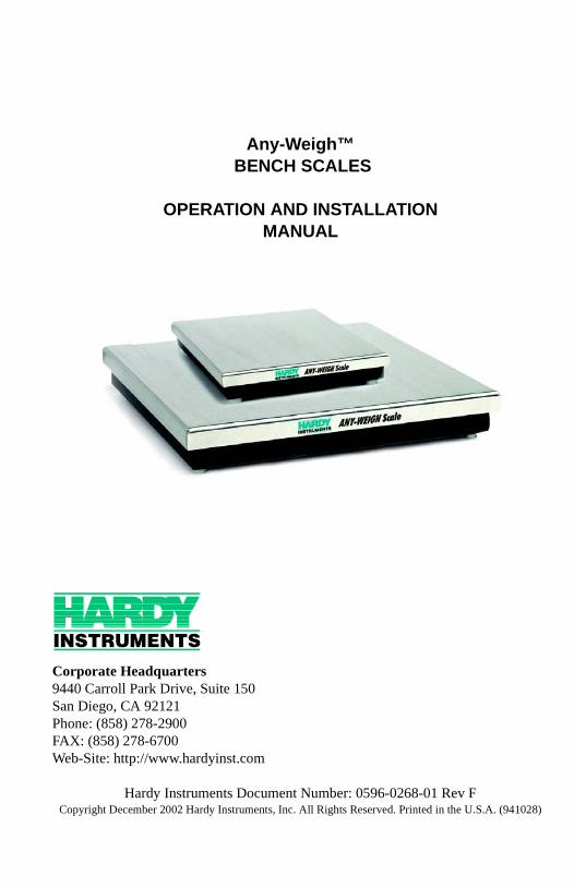
Any-Weigh™ BENCH SCALES
OPERATION AND INSTALLATIONMANUAL
Corporate Headquarters 9440 Carroll Park Drive, Suite 150San Diego, CA 92121 Phone: (858) 278-2900FAX: (858) 278-6700Web-Site: http://www.hardyinst.com
Hardy Instruments Document Number: 0596-0268-01 Rev FCopyright December 2002 Hardy Instruments, Inc. All Rights Reserved. Printed in the U.S.A. (941028)
CAUTION:
UNPACK WITH CARE
WHEN UNPACKING, DO NOT DISCARD THE PACKING CASE OR ANY PACKING MATERIAL, UNTIL THE CONTENTS OF THE PACKING CASE ARE INSPECTED AND CAREFULLY COMPARED WITH THE SHIPPING DOCUMENTS.
IF ANYTHING IS UNSATISFACTORY, PLEASE NOTIFY HARDY INSTRU-MENTS IMMEDIATELY BY CALLING, FAXING OR E-MAILING TO:
Hardy Service CenterHARDY INSTRUMENTS, INC.3860 Calle FortunadaSan Diego, California 92123-1825
Phone: (800) 821-5831(858) 278-2900FAX:(858) 278-6700
E-mail: [email protected] Address: www.hardyinst.com
TO RETURN DEFECTIVE OR DAMAGED PRODUCT(S) CALL HARDY TECHNICAL SUPPORT FOR A HARDY SERVICE TICKET NUMBER (HST#). YOUR COMPANY NAME, ADDRESS, TELEPHONE NUMBER, SERIAL NUMBER OF THE UNIT AND A BRIEF DESCRIPTION OF THE PROBLEM SHOULD BE READY WHEN CALLING. FOR ALL NON-WAR-RANTY REPAIRS A PURCHASE ORDER OR CREDIT CARD IS ALSO REQUIRED.
IN CASE OF DAMAGE DUE TO SHIPPING, NOTIFY THE DELIVERING CARRIER IMMEDIATELY FOR AN INSPECTION.
Table of Contents
Table of Contents
Chapter 1 - overview - - - - - - - - - - - - - - - - - - - - - - - -1-1Introduction - - - - - - - - - - - - - - - - - - - - - - - - - - - - -1-1Description - - - - - - - - - - - - - - - - - - - - - - - - - - - - - -1-1
The Stainless Steel Top Cover - - - - - - - - - - - - - - - - - -1-1Lower Frame Assembly - - - - - - - - - - - - - - - - - - - - -1-1Universal Scale Interface - - - - - - - - - - - - - - - - - - - - -1-1DeviceNet™ Scale - - - - - - - - - - - - - - - - - - - - - - - -1-2Analog Scale - - - - - - - - - - - - - - - - - - - - - - - - - -1-2
Chapter 2 - specifications - - - - - - - - - - - - - - - - - - - - -2-1Electrical Specifications - - - - - - - - - - - - - - - - - - - - - - -2-1
Universal Scale Specifications - - - - - - - - - - - - - - - - - -2-1DeviceNet Scale Specifications - - - - - - - - - - - - - - - - - -2-2Analog Scale Specifications - - - - - - - - - - - - - - - - - - -2-2
Mechanical Dimensions - - - - - - - - - - - - - - - - - - - - - - -2-3
Chapter 3 - installation - - - - - - - - - - - - - - - - - - - - - - -3-1Preinstallation Precautions - - - - - - - - - - - - - - - - - - - - - -3-1Unpacking - - - - - - - - - - - - - - - - - - - - - - - - - - - - - -3-1Leveling the Scale - - - - - - - - - - - - - - - - - - - - - - - - - -3-1Universal Scale Electrical Connections - - - - - - - - - - - - - - - -3-3
DeviceNet Scale: Connecting to a DeviceNet Network - - - - - -3-4DeviceNet Connection Wiring Diagram - - - - - - - - - - - -3-4
Analog Scale - - - - - - - - - - - - - - - - - - - - - - - - - -3-5
Chapter 4 - configuration - - - - - - - - - - - - - - - - - - - - - -4-1SCOPE 4-1DeviceNet Communication Configuration - - - - - - - - - - - - - - - 4-1
DIP Switch (S1) Configuration - - - - - - - - - - - - - - - - - -4-1DIP Switch Location - - - - - - - - - - - - - - - - - - - - - - -4-1Accessing the DIP Switch - - - - - - - - - - - - - - - - - - - -4-2Configuring the Baud Rate - - - - - - - - - - - - - - - - - - - -4-2Configuring the DeviceNet Node Address - - - - - - - - - - - - -4-2
Chapter 5 - Setup - - - - - - - - - - - - - - - - - - - - - - - - - -5-1SCOPE - - - - - - - - - - - - - - - - - - - - - - - - - - - - - - -5-1Saving to Non-Volatile Ram- - - - - - - - - - - - - - - - - - - - - -5-1Parameters - - - - - - - - - - - - - - - - - - - - - - - - - - - - -5-1
Command Interface - - - - - - - - - - - - - - - - - - - - - - -5-4Format of Commands (4 byte input data) - - - - - - - - - - -5-4Examples Using the Command Interface - - - - - - - - - - -5-5
i
Any-Weigh™ Series Bench Scales
Chapter 6 - calibration - - - - - - - - - - - - - - - - - - - - - - -6-1Calibration of the DeviceNet, Analog and Universal Bench Scales - - -6-1C2 Second Generation Calibration - - - - - - - - - - - - - - - - - -6-1Test Weight Calibration (Hard Cal) - - - - - - - - - - - - - - - - - -6-1Material Substitution - - - - - - - - - - - - - - - - - - - - - - - - -6-1Universal Scales HI SBU Series - - - - - - - - - - - - - - - - - - -6-1DeviceNet Scales HI SBD Series - - - - - - - - - - - - - - - - - - -6-1THE BUTTON® - - - - - - - - - - - - - - - - - - - - - - - - - - -6-2C2® Calibration from RS NetWorx® - - - - - - - - - - - - - - - - -6-2Test Weight Calibration from RS NetWorx® - - - - - - - - - - - - - -6-3Analog Scales HI SBA Series - - - - - - - - - - - - - - - - - - - -6-4
Calibration Controls - - - - - - - - - - - - - - - - - - - - - - -6-4Coarse (ZERO) - - - - - - - - - - - - - - - - - - - - - - -6-4Fine (ZERO) - - - - - - - - - - - - - - - - - - - - - - - - -6-4Span - - - - - - - - - - - - - - - - - - - - - - - - - - - -6-4Calibration Procedures - - - - - - - - - - - - - - - - - - - -6-5
Chapter 7 - OPERATION - - - - - - - - - - - - - - - - - - - - - -7-1Scope - - - - - - - - - - - - - - - - - - - - - - - - - - - - - - - -7-1Operating Capabilities - - - - - - - - - - - - - - - - - - - - - - - -7-1DeviceNet Scale - - - - - - - - - - - - - - - - - - - - - - - - - - -7-1
Explicit Message Request Parameters - - - - - - - - - - - - - -7-1Monitoring Weight Readings from RS NetWorx - - - - - - - - - -7-2Network Status (DS1) - - - - - - - - - - - - - - - - - - - - - -7-2Scale Status (DS2) - - - - - - - - - - - - - - - - - - - - - - - -7-2
Analog Scale - - - - - - - - - - - - - - - - - - - - - - - - - - - - -7-3
Chapter 8 - Troubleshooting 8-1Scope - - - - - - - - - - - - - - - - - - - - - - - - - - - - - - - -8-1Problem: - - - - - - - - - - - - - - - - - - - - - - - - - - - - - - -8-1
Scale Does Not Respond When Weight is Applied - - - - - - - -8-1Scale Indication is not linear - - - - - - - - - - - - - - - - - - -8-1Scale Reads Backwards - - - - - - - - - - - - - - - - - - - - -8-1Scale Reading drifts or is Erratic - - - - - - - - - - - - - - - - -8-1DeviceNet Scale: Module LED does not Come Back on When Performing Calibration with The Button - - - - - - - - - - -8-2DeviceNet Scale: Module LED is Flashing Red - - - - - - - - - -8-2Analog Scale: Malfunction, No Output - - - - - - - - - - - - - -8-2Analog Scale: No Change in Input - - - - - - - - - - - - - - - -8-2Analog Scale: Output Drifts - - - - - - - - - - - - - - - - - - - -8-2
Service and Repair (All Models) - - - - - - - - - - - - - - - - - - -8-2
Index - - - - - - - - - - - - - - - - - - - - - - - - - - - - - - - -1-1
ii

Table of Illustrations
Table of Illustrations
CHAPTER 2 - SPECIFICATIONS- - - - - - - - - - - - - - - - - - -2-1
FIG. 2-1 A DIMENSION- - - - - - - - - - - - - - - - - - - - - - -2-3FIG. 2-2 B DIMENSION- - - - - - - - - - - - - - - - - - - - - - -2-3
CHAPTER 3 - INSTALLATION - - - - - - - - - - - - - - - - - - - -3-1
FIG. 3-1 LEVELING CORNERS- - - - - - - - - - - - - - - - - - -3-2FIG. 3-2 LEVELING FEET - - - - - - - - - - - - - - - - - - - - -3-2FIG. 3-3 LEVELING SCALE- - - - - - - - - - - - - - - - - - - - -3-3FIG. 3-4 DEVICENET CONNECTOR - - - - - - - - - - - - - - - -3-4FIG. 3-5 VIEWED FROM THE WIRE PIN SIDE - - - - - - - - - - -3-5FIG. 3-6 VIEWED FROM THE SOCKET SIDE- - - - - - - - - - - -3-5FIG. 3-7 ANALOG SCALE/OUTPUT/POWER LOOP WIRING - - - -3-6
CHAPTER 4 - CONFIGURATION- - - - - - - - - - - - - - - - - - -4-1
FIG. 4-1 DIP SWITCH LOCATION/BOTTOM VIEW - - - - - - - - -4-1FIG. 4-2 FACTORY DEFAULT DIP SWITCH CONFIGURATION- - -4-2
CHAPTER 6 - CALIBRATION - - - - - - - - - - - - - - - - - - - -6-1
FIG. 6-1 THE BUTTON LOCATION/BOTTOM VIEW- - - - - - - - -6-2
I

Any-Weigh™ Series Bench Scales
II
Chapter 1 - Overview
CHAPTER 1 - OVERVIEW
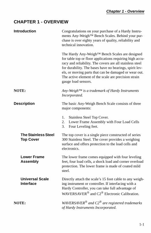
Introduction Congratulations on your purchase of a Hardy Instru-ments Any-Weigh™ Bench Scales. Behind your pur-chase is over eighty years of quality, reliability and technical innovation.
The Hardy Any-Weigh™ Bench Scales are designed for table top or floor applications requiring high accu-racy and reliability. The covers are all stainless steel for durability. The bases have no bearings, spirit lev-els, or moving parts that can be damaged or wear out. The active element of the scale are precision strain gauge load sensors.
NOTE: Any-Weigh™ is a trademark of Hardy Instruments Incorporated.
Description The basic Any-Weigh Bench Scale consists of three major components:
1. Stainless Steel Top Cover.2. Lower Frame Assembly with Four Load Cells3. Four Leveling feet.
The Stainless Steel Top Cover
The top cover is a single piece constructed of series 300 Stainless Steel. The cover provides a weighing surface and offers protection to the load cells and electronics.
Lower Frame Assembly
The lower frame comes equipped with four leveling feet, four load cells, a shock load and corner overload protection. The lower frame is made of coated mild steel.
Universal Scale Interface
Directly attach the scale’s 15 foot cable to any weigh-ing instrument or controller. If interfacing with a Hardy Controller, you can take full advantage of
WAVERSAVER® and C2® Electronic Calibration.
NOTE: WAVERSAVER® and C2® are registered trademarks of Hardy Instruments Incorporated.
1-1
Any-Weigh™ Series Bench Scales
DeviceNet™ Scale With DeviceNet™ you can use the scale to provide a weight output to any point on a DeviceNet™ Net-work. This version also incorporates both the
WAVERSAVER® and C2® technologies. The DeviceNet™ Scale comes with a fifteen inch mini-mum length pig-tail connector.
NOTE: DeviceNet™ is a trademark of the Open DeviceNet Vendor Association.
Analog Scale The Analog Scale provides a 4-20mA output directly proportional to the weight reading. This version offers a low-cost, solution for bringing analog weight read-ings directly into a control system. The Analog Scale requires minimal additional wiring or hardware and comes with a 15 foot shielded 2 wire cable.
1-2
Chapter 2 - Specifications
CHAPTER 2 - SPECIFICATIONS
Electrical Specifications
Universal Scale Specifications
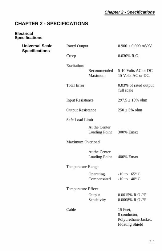
Rated Output 0.900 ± 0.009 mV/V
Creep 0.030% R.O.
Excitation:Recommended 5-10 Volts AC or DCMaximum 15 Volts AC or DC.
Total Error 0.03% of rated output full scale
Input Resistance 297.5 ± 10% ohm
Output Resistance 250 ± 5% ohm
Safe Load Limit
At the CenterLoading Point 300% Emax
Maximum Overload
At the CenterLoading Point 400% Emax
Temperature Range
Operating -10 to +65° CCompensated -10 to +40° C
Temperature Effect
Output 0.0015% R.O./oFSensitivity 0.0008% R.O./°F
Cable 15 Feet, 8 conductor, Polyurethane Jacket,Floating Shield
2-1
Any-Weigh™ Series Bench Scales
DeviceNet Scale Specifications
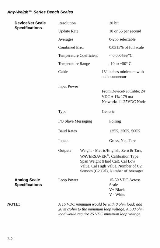
Resolution 20 bit
Update Rate 10 or 55 per second
Averages 0-255 selectable
Combined Error 0.0315% of full scale
Temperature Coefficient < 0.0005%/°C
Temperature Range -10 to +50° C
Cable 15” inches minimum with male connector
Input PowerFrom DeviceNet Cable: 24 VDC ± 1% 179 ma Network/ 11-25VDC Node
Type Generic
I/O Slave Messaging Polling
Baud Rates 125K, 250K, 500K
Inputs Gross, Net, Tare
Outputs Weight - Metric/English, Zero & Tare,
WAVERSAVER®, Calibration Type, Span Weight (Hard Cal), Cal Low Value, Cal High Value, Number of C2 Sensors (C2 Cal), Number of Averages
Analog Scale Specifications
Loop Power 15-50 VDC Across ScaleV+ BlackV - White
NOTE: A 15 VDC minimum would be with 0 ohm load; add 20 mV/ohm to the minimum loop voltage. A 500 ohm load would require 25 VDC minimum loop voltage.
2-2
Chapter 2 - Specifications
Linearity* 0.11% of full scale
* Some barrier protection is required where the unit is located in a hazardous area.
Response Time 250 milliseconds
Sensitivity 3 mV/V of full scale with adjustment to 2 mV/V
Temperature Range 0 to +60° C
Temperature Coefficient 10.025%/° C
Cable 15 Feet
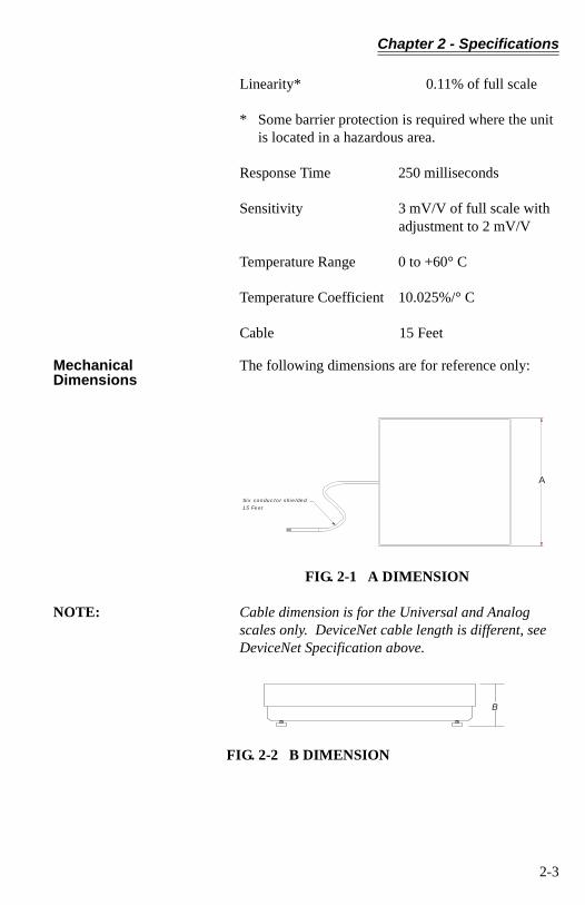
Mechanical Dimensions
The following dimensions are for reference only:
FIG. 2-1 A DIMENSION
NOTE: Cable dimension is for the Universal and Analog scales only. DeviceNet cable length is different, see DeviceNet Specification above.
FIG. 2-2 B DIMENSION
Six conductor shielded
15 Feet
A
B
2-3
Any-Weigh™ Series Bench Scales
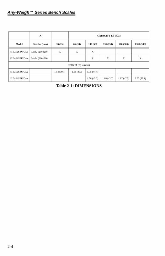
A CAPACITY LB (KG)
Model Size In. (mm) 33 (15) 66 (30) 130 (60) 330 (150) 660 (300) 1300 (590)
HI 1212SBU/D/A 12x12 (298x298) X X X
HI 2424SBU/D/A 24x24 (600x600) X X X X
HEIGHT (B) in (mm)
HI 1212SBU/D/A 1.54 (39.1) 1.56 (39.6 1.75 (44.4)
HI 2424SBU/D/A 1.78 (45.2) 1.68 (42.7) 1.87 (47.5) 2.05 (52.1)
Table 2-1: DIMENSIONS
2-4
Chapter 3 - Installation
CHAPTER 3 - INSTALLATION
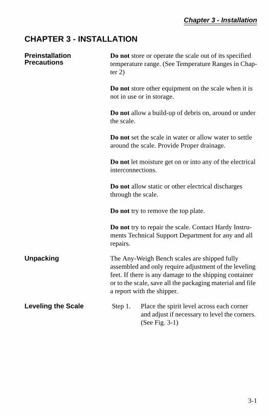
Preinstallation Precautions
Do not store or operate the scale out of its specified temperature range. (See Temperature Ranges in Chap-ter 2)
Do not store other equipment on the scale when it is not in use or in storage.
Do not allow a build-up of debris on, around or under the scale.
Do not set the scale in water or allow water to settle around the scale. Provide Proper drainage.
Do not let moisture get on or into any of the electrical interconnections.
Do not allow static or other electrical discharges through the scale.
Do not try to remove the top plate.
Do not try to repair the scale. Contact Hardy Instru-ments Technical Support Department for any and all repairs.
Unpacking The Any-Weigh Bench scales are shipped fully assembled and only require adjustment of the leveling feet. If there is any damage to the shipping container or to the scale, save all the packaging material and file a report with the shipper.
Leveling the Scale Step 1. Place the spirit level across each corner and adjust if necessary to level the corners. (See Fig. 3-1)
3-1
Any-Weigh™ Series Bench Scales
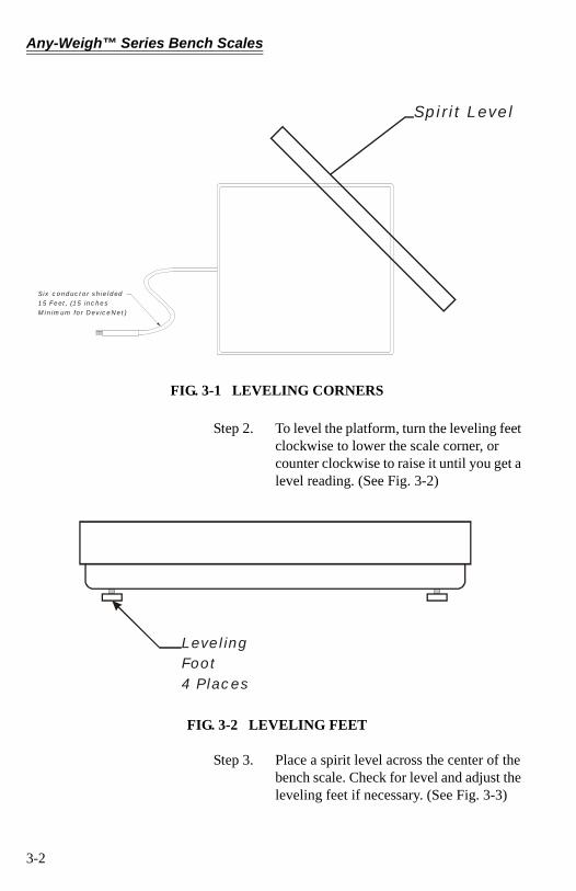
FIG. 3-1 LEVELING CORNERS
Step 2. To level the platform, turn the leveling feet clockwise to lower the scale corner, or counter clockwise to raise it until you get a level reading. (See Fig. 3-2)
FIG. 3-2 LEVELING FEET
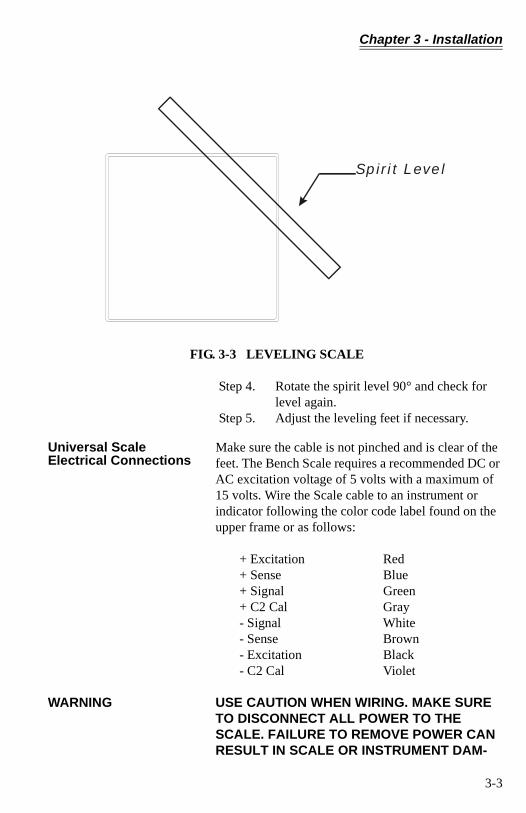
Step 3. Place a spirit level across the center of the bench scale. Check for level and adjust the leveling feet if necessary. (See Fig. 3-3)
Six conductor shielded15 Feet, (15 inchesMinimum for DeviceNet)
Spirit Level
LevelingFoot4 Places
3-2
Chapter 3 - Installation
FIG. 3-3 LEVELING SCALE
Step 4. Rotate the spirit level 90° and check for level again.
Step 5. Adjust the leveling feet if necessary.
Universal Scale Electrical Connections
Make sure the cable is not pinched and is clear of the feet. The Bench Scale requires a recommended DC or AC excitation voltage of 5 volts with a maximum of 15 volts. Wire the Scale cable to an instrument or indicator following the color code label found on the upper frame or as follows:
+ Excitation Red+ Sense Blue+ Signal Green+ C2 Cal Gray- Signal White- Sense Brown- Excitation Black- C2 Cal Violet
WARNING USE CAUTION WHEN WIRING. MAKE SURE TO DISCONNECT ALL POWER TO THE SCALE. FAILURE TO REMOVE POWER CAN RESULT IN SCALE OR INSTRUMENT DAM-
Spirit Level
3-3
Any-Weigh™ Series Bench Scales
AGE, DEGRADATION OF PERFORMANCE OR PERSONAL INJURY
DeviceNet Scale: Connecting to a DeviceNet Network
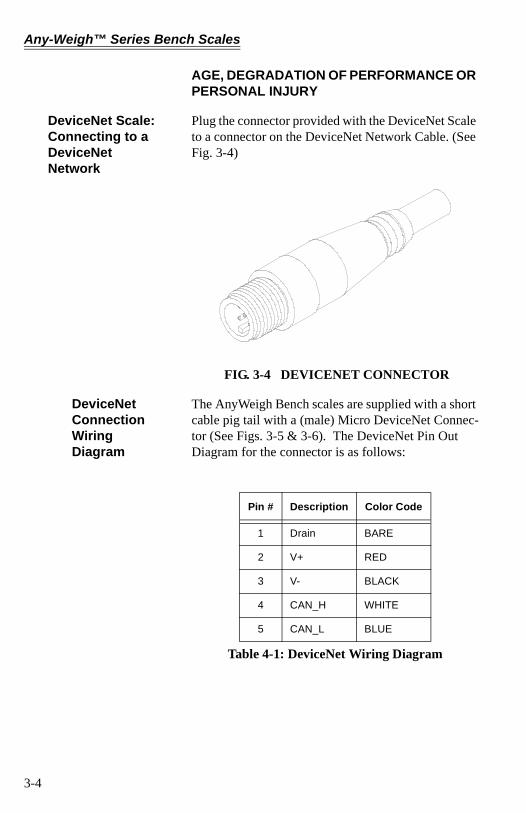
Plug the connector provided with the DeviceNet Scale to a connector on the DeviceNet Network Cable. (See Fig. 3-4)
FIG. 3-4 DEVICENET CONNECTOR
DeviceNet Connection Wiring Diagram
The AnyWeigh Bench scales are supplied with a short cable pig tail with a (male) Micro DeviceNet Connec-tor (See Figs. 3-5 & 3-6). The DeviceNet Pin Out Diagram for the connector is as follows:
Pin # Description Color Code
1 Drain BARE
2 V+ RED
3 V- BLACK
4 CAN_H WHITE
5 CAN_L BLUE
Table 4-1: DeviceNet Wiring Diagram
3-4
Chapter 3 - Installation
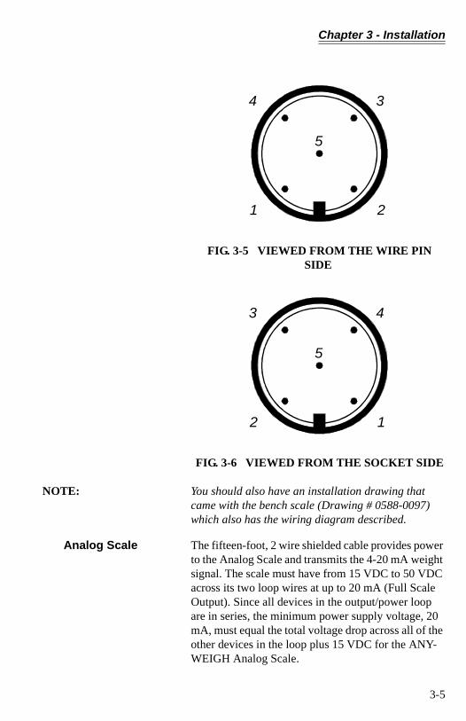
FIG. 3-5 VIEWED FROM THE WIRE PIN SIDE
FIG. 3-6 VIEWED FROM THE SOCKET SIDE
NOTE: You should also have an installation drawing that came with the bench scale (Drawing # 0588-0097) which also has the wiring diagram described.
Analog Scale The fifteen-foot, 2 wire shielded cable provides power to the Analog Scale and transmits the 4-20 mA weight signal. The scale must have from 15 VDC to 50 VDC across its two loop wires at up to 20 mA (Full Scale Output). Since all devices in the output/power loop are in series, the minimum power supply voltage, 20 mA, must equal the total voltage drop across all of the other devices in the loop plus 15 VDC for the ANY-WEIGH Analog Scale.
5
1
4
2
3
5
2
3
1
4
3-5

Any-Weigh™ Series Bench Scales
Carefully note which wire is connected in the loop to maintain correct polarity within the loop. To reduce the change of ground loops do not connect any of the scales signal wires to earth ground. (See Fig. 3-7)
FIG. 3-7 ANALOG SCALE/OUTPUT/POWER LOOP WIRING
RECEIVER#1
RECEIVER#2
RECEIVER#3
PowerSupply
Transmitter
Analog Scale
4mA - 20mA
3-6
Chapter 4 - Configuration
CHAPTER 4 - CONFIGURATION
SCOPE The Universal Scale and the Analog Scale do not require any configuration. The DeviceNet scale con-figuration consists of setting the baud rate and node address on a DIP switch which is accessible through an access port on the bottom of the scale.
DeviceNet Communication Configuration
NOTE: Be sure to configure the DeviceNet Scale before plac-ing any vessels or containers on the scale.
DIP Switch (S1) Configuration
Configuring the DIP switch sets the following:
1. Baud Rate2. Node Address
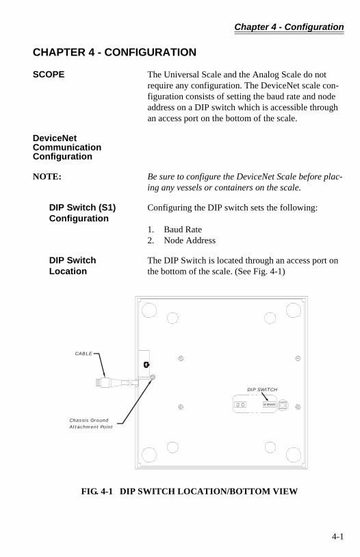
DIP Switch Location
The DIP Switch is located through an access port on the bottom of the scale. (See Fig. 4-1)
FIG. 4-1 DIP SWITCH LOCATION/BOTTOM VIEW
Chassis GroundAttachment Point
CABLE
DIP SWITCH
4-1

Any-Weigh™ Series Bench Scales
Accessing the DIP Switch
Tilt the scale up until you can reach the DIP Switch access port or if it is more convenient turn the scale upside down so that bottom is facing up to reach the DIP Switch access port.
NOTE: Scale must be connected to earth ground from the Chassis Ground Attachment Point. (See Fig. 4-1)
Configuring the Baud Rate
Refer to Table 4-1 to configure the baud rate. 0 = OFF, 1 = ON (* is the default setting)
FIG. 4-2 FACTORY DEFAULT DIP SWITCH CONFIGURATION
Configuring the DeviceNet Node Address
Refer to Table 4-2 to configure the DeviceNet Node Address.
Baud Rate S1-7 S1-8
125 kbps* OFF OFF
250 kbps OFF ON
500 kbps ON OFF
500 kbps ON ON
Table 4-1: Baud Rate
4-2

Chapter 4 - Configuration
Address S1-1 S1-2 S1-3 S1-4 S1-5 S1-6
0 OFF OFF OFF OFF OFF OFF
1 OFF OFF OFF OFF OFF ON
2 OFF OFF OFF OFF ON OFF
3 OFF OFF OFF OFF ON ON
“ “ “ “ “ “ “
62 ON ON ON ON ON OFF
63 ON ON ON ON ON ON
Table 4-2: DeviceNet Node Addresses
4-3

Any-Weigh™ Series Bench Scales
4-4
Chapter 5 - Setup
CHAPTER 5 - SETUP
SCOPE All information contained in Chapter 5 pertains to software or firmware settings or procedures to prepare the DeviceNet Scale for calibration and operation. Alternatives to these procedures either explicit or implied, contained in this section are not recom-mended. It is very important that the user and service personnel be familiar with the procedures contained in this chapter, before going through the setup proce-dures.
NOTE: The DeviceNet Scale is the only scale in the ANY-WEIGH series of scales that requires a setup. The Analog Scale requires calibration, please see Chapter 6 for the Analog Scale calibration procedures.
Saving to Non-Volatile Ram
To save parameters to non-volatile RAM, set parame-ter 38 (Save non-volatile command) to 1.This request should be sent after changing any config-uration parameter. It does NOT need to be sent after altering a command parameters like TARE or ZERO. It does not need to be sent after doing a calibration. The necessary calibration data values are saved auto-matically. However, if you change parameters used during calibration, like “number of averages”, or
“WAVERSAVER®” for example, the SAVE request should be sent BEFORE cycling the power.
The non-volatile RAM has a maximum of 5,000,000 writes.
Parameters • Parameter 1 = Metric PollTrue = kgs net False = lbs netLength in Bytes = 1
NOTE: Default settings are indicated by bold type.
• Parameter 2 = WAVERSAVER® Setting0 =OFF 1 = 4 Hz, 2 = 2Hz, 3 = 1.0 Hz, 4 = 1/2 HzLength in Bytes = 1
5-1
Any-Weigh™ Series Bench Scales
NOTE: By selecting OFF (0) or 1 the scale increases the updates per second from 10 to 55.
• Parameter 3 = Calibration Type0 = Hard Cal, 1 = C2 Cal, Other = Not Cal’d(Read Only)Length in Bytes = 1
• Parameter 4 = Span Weight in Lbs1 to 2147483647 10000.000Length in Bytes = 4
• Parameter 5 = Averages0 to 255 10Length in Bytes = 1
• Parameter 14 = Number of C2® Chips Found0 to 8 (Read Only)Length in Bytes = 1
• Parameter 15 = Net Weight in LbsRead Only Length in Bytes = 4
• Parameter 16 = Gross Weight in LbsRead OnlyLength in Bytes = 4
• Parameter 17 = Tare Weight in Lbs-999999 - 999999 0.00Length in Bytes = 4
• Parameter 18 = Tare Command0 to 1 (Set to True to Complete Command)Length in Bytes = 1
• Parameter 19 = Zero Command0 to 1 (Set to True to Complete Command)Length in Bytes = 1
• Parameter 20 = Calibrate Low Command0 to 1 (Set to True to Complete Command)Length in Bytes = 1
5-2
Chapter 5 - Setup
• Parameter 21 = Calibrate High Command0 to 1 (Set to True to Complete Command)Length in Bytes = 1
• Parameter 22 = Calibrate using C2® 0 to 1 (Set to True to Complete Command)Length in Bytes = 1
• Parameter 23 = Span Weight in Kgs0.000 to 2147483.647 0.045Length in Bytes = 4
• Parameter 30 = Net Weight in KgsRead OnlyLength in Bytes = 4
• Parameter 31 = Gross Weight in KgsRead OnlyLength in Bytes = 4
• Parameter 32 = Tare Weight in Kgs-999999 - 999999 0.00Length in Bytes = 4
• Parameter 34 = A/D CountsLength in Bytes = 4
• Parameter 35 = Calibration Low Weight in Lbs.Length in Bytes = 4
• Parameter 36 = Calibration Low Weight in Kgs.Length in Bytes = 4
The “Calibration Low Weight” parameter speci-fies the weight on the scale when the low step of a calibration is done in Traditional Calibration and is the Reference Point for C2 Calibration.
• Parameter 37 = Weight MultiplierLength in Bytes = 4
This integer parameter can be set to 1, 10, 100, etc. to allow the user to select the number of dec-
5-3
Any-Weigh™ Series Bench Scales
imal places in the 32 bit integer weight outputs. The value 0 causes these weight outputs to be in floating point format.
NOTE: This applies ONLY to the weights as viewed through the I/O (Command) interface. The explicit message interface continues to use 3 decimal place 32 bit inte-ger format only.
• Parameter 38 = Write non-volatile command.Length in Bytes = 1
Setting this parameter to 1 will cause a save to non-volatile memory. Calibration data is saved to non-volatile memory automatically. Other param-eters must be saved using this command.
• Parameter 30 = Parameter high word.Length in Bytes = 2This parameter is used in the command interface as described below:
Command Interface
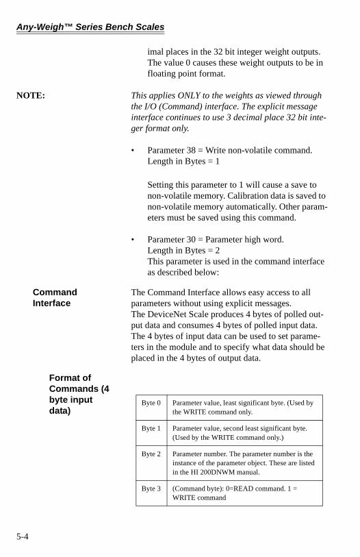
The Command Interface allows easy access to all parameters without using explicit messages.The DeviceNet Scale produces 4 bytes of polled out-put data and consumes 4 bytes of polled input data. The 4 bytes of input data can be used to set parame-ters in the module and to specify what data should be placed in the 4 bytes of output data.
Format of Commands (4 byte input data)
Byte 0 Parameter value, least significant byte. (Used by the WRITE command only.
Byte 1 Parameter value, second least significant byte. (Used by the WRITE command only.)
Byte 2 Parameter number. The parameter number is the instance of the parameter object. These are listed in the HI 200DNWM manual.
Byte 3 (Command byte): 0=READ command. 1 = WRITE command
5-4
Chapter 5 - Setup
Most of the DeviceNet Scales’ parameters are only 1 byte long, making it possible to write them with a sin-gle command. There are also some 4 byte parameters. To write one of them:
Step 1. First write the 2 most significant bytes, using a WRITE command as described above, with 0x27 in the parameter number field.
Step 2. Write the least significant bytes using nor-mal parameter numbers. The module will combine the value written to parameter 0x27 with the least significant bytes to produce the value written to the 4 byte parameter.
The 4 bytes written to the output table are as follows:
• If the Command byte of the input data is 0 (READ), the data is the value of the specified parameter, least significant byte first.
• If the specified parameter is an invalid number (0 for example: there is no parameter number 0), the data is net weight, with units as determined by the METRIC POLL parameter.
• If the Command byte of the input data is non-zero (WRITE), the output data echoes the input data.
Examples Using the Command Interface
Reading Gross Weight in the polled output data.
1. First word (2 least significant bytes) of the input data is not used. Ignore.
2. Lower byte of second word is the parameter num-ber. Gross weight in lbs is parameter #16.
3. Upper byte of second word set is “0” indicating read.
This causes the unit to output the Gross weight in lbs to the output polled data area. Resolution and data type would depend on the Weight Multiplier setting.Writing new value to number of averages.
5-5
Any-Weigh™ Series Bench Scales
1. First byte of first word on the input data is the new valued wanted.
2. Upper byte of first word should be 0 and is not used.
3. Lower byte of second word is the parameter num-ber. Averages is parameter #5.
4. Upper byte of second word is set to “1” to indi-cate write.
This causes the unit to write the value in the first byte of the first word to the Averages parameter. During the execution of the command, the output polled data reflects the input polled data.
5-6
Chapter 6 - Calibration
CHAPTER 6 - CALIBRATION
About Calibration of the DeviceNet, Analog and Universal Bench Scales
The DeviceNet and Analog version of bench scales come pre-calibrated from the factory. For the Univer-sal version make sure it is correctly wired to the weighing instrument/indicator. Refer to the weighing instrument/indicator manual for calibration instruc-tions.
C2 Second Generation Calibration
C2 electronically calibrates a scale system without the need for test weights. If you are using a Hardy Instru-ments Controller, Indicator or Weigh Module, all that’s required is to enter a reference point. Refer to the instrument or module manual for instructions.
Test Weight Calibration (Hard Cal)
This is the traditional means of calibration requiring certified class F test weights equal to a minimum of 80% of the rated scale capacity. Additionally three weights between 10% and 100% of the scale capacity should be available to check the mid-range. Several low capacity weights equivalent to one or two instru-ment divisions are necessary to check the system sen-sitivity.
Material Substitution When certified test weights are not available you can use an accurately weighed material to calibrate the system. In this method, a material is weighed on a secondary, calibrated scale and delivered to the site of the scale to be calibrated. The secondary calibrated scale should be of the same accuracy or greater and have a capacity approximately equal to the scale being calibrated.
Universal Scales HI SBU Series
Refer to the weighing instrument or module manual
for calibration instructions. C2® Second Generation Calibration should only be used with Hardy weighing instruments.
DeviceNet Scales HI SBD Series
The ANY-WEIGH DeviceNet Scale series come pre-calibrated from the factory. If additional dead load is permanently attached to the scale surface, a recalibra-tion may need to be performed.
6-1
Any-Weigh™ Series Bench Scales
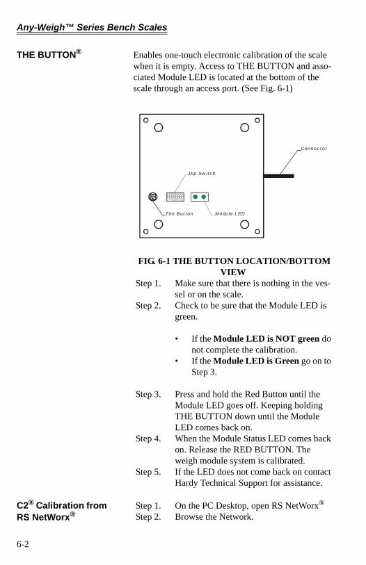
THE BUTTON® Enables one-touch electronic calibration of the scale when it is empty. Access to THE BUTTON and asso-ciated Module LED is located at the bottom of the scale through an access port. (See Fig. 6-1)
FIG. 6-1 THE BUTTON LOCATION/BOTTOM VIEW
Step 1. Make sure that there is nothing in the ves-sel or on the scale.
Step 2. Check to be sure that the Module LED is green.
• If the Module LED is NOT green do not complete the calibration.
• If the Module LED is Green go on to Step 3.
Step 3. Press and hold the Red Button until the Module LED goes off. Keeping holding THE BUTTON down until the Module LED comes back on.
Step 4. When the Module Status LED comes back on. Release the RED BUTTON. The weigh module system is calibrated.
Step 5. If the LED does not come back on contact Hardy Technical Support for assistance.
C2® Calibration from RS NetWorx®
Step 1. On the PC Desktop, open RS NetWorx®
Step 2. Browse the Network.
Connector
The Button
Dip Switch
Module LED
6-2
Chapter 6 - Calibration
Step 3. Double click on the Node Icon of the weigh module you want to calibrate. For example: Node 36. The DeviceNet Weigh Module Dialog Box appears.
Step 4. Click on the Parameter tab. The Parameter List appears with the information for the weigh module at address 36.
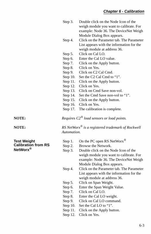
Step 5. Click on Cal LO. Step 6. Enter the Cal LO value. Step 7. Click on the Apply button. Step 8. Click on Yes. Step 9. Click on C2 Cal Cmd. Step 10. Set the C2 Cal Cmd to “1”. Step 11. Click on the Apply button. Step 12. Click on Yes. Step 13. Click on Cmd Save non-vol. Step 14. Set the Cmd Save non-vol to “1”. Step 15. Click on the Apply button. Step 16. Click on Yes. Step 17. The calibration is complete.
NOTE: Requires C2® load sensors or load points.
NOTE: RS NetWorx® is a registered trademark of Rockwell Automation.
Test Weight Calibration from RS NetWorx®
Step 1. On the PC open RS NetWorx®
Step 2. Browse the Network. Step 3. Double click on the Node Icon of the
weigh module you want to calibrate. For example: Node 36. The DeviceNet Weigh Module Dialog Box appears.
Step 4. Click on the Parameter tab. The Parameter List appears with the information for the weigh module at address 36.
Step 5. Click on Span Weight. Step 6. Enter the Span Weight Value. Step 7. Click on Cal LO. Step 8. Enter the Cal LO weight. Step 9. Click on Cal LO command. Step 10. Set the Cal LO to “1”. Step 11. Click on the Apply button. Step 12. Click on Yes.
6-3
Any-Weigh™ Series Bench Scales
Step 13. Place the test weight on the scale. Step 14. Click on Cal HI command. Step 15. Set the Cal HI command to “1” Step 16. Click on the Apply button. Step 17. Click on Yes. Step 18. Click on Cmd Save non-vol. Step 19. Set the Cmd Save non-vol to “1”. Step 20. Click on the Apply button. Step 21. Click on Yes. Step 22. The calibration is complete. Step 23. Click on Yes. Step 24. The calibration is complete.
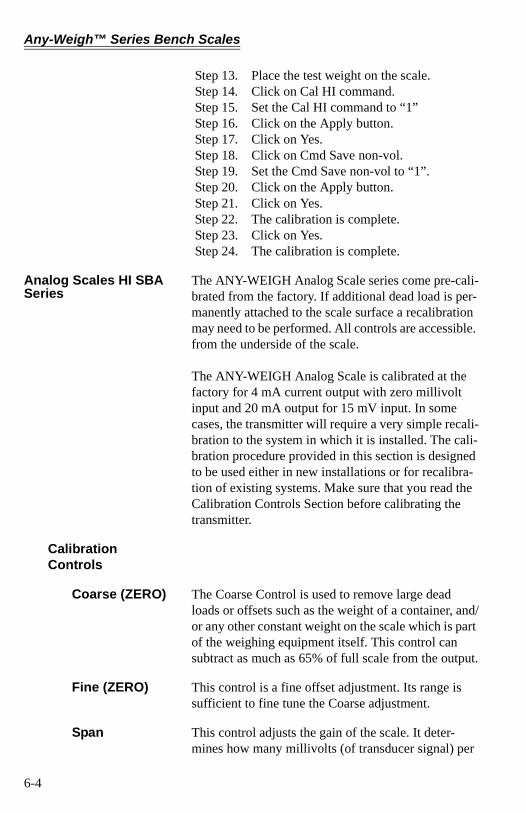
Analog Scales HI SBA Series
The ANY-WEIGH Analog Scale series come pre-cali-brated from the factory. If additional dead load is per-manently attached to the scale surface a recalibration may need to be performed. All controls are accessible. from the underside of the scale.
The ANY-WEIGH Analog Scale is calibrated at the factory for 4 mA current output with zero millivolt input and 20 mA output for 15 mV input. In some cases, the transmitter will require a very simple recali-bration to the system in which it is installed. The cali-bration procedure provided in this section is designed to be used either in new installations or for recalibra-tion of existing systems. Make sure that you read the Calibration Controls Section before calibrating the transmitter.
Calibration Controls
Coarse (ZERO) The Coarse Control is used to remove large dead loads or offsets such as the weight of a container, and/or any other constant weight on the scale which is part of the weighing equipment itself. This control can subtract as much as 65% of full scale from the output.
Fine (ZERO) This control is a fine offset adjustment. Its range is sufficient to fine tune the Coarse adjustment.
Span This control adjusts the gain of the scale. It deter-mines how many millivolts (of transducer signal) per
6-4
Chapter 6 - Calibration
volt (of transducer excitation) will be represented by the 4-20 mA output range.
The gain can be adjusted from 3 mV input per volt of excitation to as high as 0.8 mV input per volt of exci-tation. This broad range of sensitivity allows for the wide variation in transducer range that remains after dead load compensation is subtracted by the Coarse Zero adjustment.
Calibration Procedures
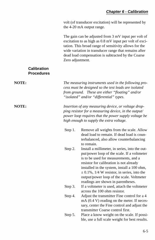
NOTE: The measuring instruments used in the following pro-cess must be designed so the test leads are isolated from ground. These are either “floating” and/or “isolated” and/or “differential” types.
NOTE: Insertion of any measuring device, or voltage drop-ping resistor for a measuring device, in the output/power loop requires that the power supply voltage be high enough to supply the extra voltage.
Step 1. Remove all weights from the scale. Allow dead load to remain. If dead load is coun-terbalanced, also allow counterbalancing to remain.
Step 2. Install a millimeter, in series, into the out-put/power loop of the scale. If a voltmeter is to be used for measurements, and a resistor for calibration is not already installed in the system, install a 100 ohm, ± 0.1%, 1/4 W resistor, in series, into the output/power loop of the scale. Voltmeter readings are shown in parentheses.
Step 3. If a voltmeter is used, attach the voltmeter across the 100 ohm resistor.
Step 4. Adjust the transmitter Fine control for a 4 mA (0.4 V) reading on the meter. If neces-sary, center the Fine control and adjust the transmitter Coarse control first.
Step 5. Place a know weight on the scale. If possi-ble, use a full scale weight for best results.
6-5
Any-Weigh™ Series Bench Scales
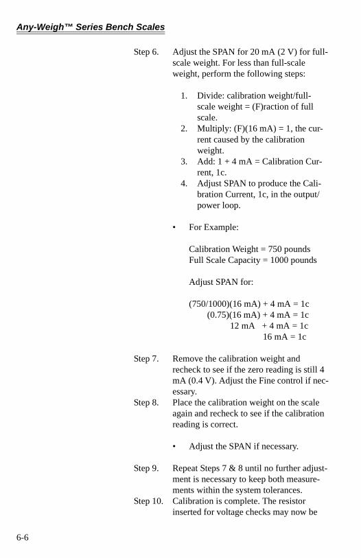
Step 6. Adjust the SPAN for 20 mA (2 V) for full-scale weight. For less than full-scale weight, perform the following steps:
1. Divide: calibration weight/full-scale weight = (F)raction of full scale.
2. Multiply: (F)(16 mA) = 1, the cur-rent caused by the calibration weight.
3. Add: 1 + 4 mA = Calibration Cur-rent, 1c.
4. Adjust SPAN to produce the Cali-bration Current, 1c, in the output/power loop.
• For Example:
Calibration Weight = 750 poundsFull Scale Capacity = 1000 pounds
Adjust SPAN for:
(750/1000)(16 mA) + 4 mA = 1c (0.75)(16 mA) + 4 mA = 1c
12 mA + 4 mA = 1c16 mA = 1c
Step 7. Remove the calibration weight and recheck to see if the zero reading is still 4 mA (0.4 V). Adjust the Fine control if nec-essary.
Step 8. Place the calibration weight on the scale again and recheck to see if the calibration reading is correct.
• Adjust the SPAN if necessary.
Step 9. Repeat Steps 7 & 8 until no further adjust-ment is necessary to keep both measure-ments within the system tolerances.
Step 10. Calibration is complete. The resistor inserted for voltage checks may now be
6-6

Chapter 6 - Calibration
removed, or it can be left in the circuit for future measurements. Neither action will interfere with the system operation.
6-7

Any-Weigh™ Series Bench Scales
6-8
Chapter 7 - Operation
CHAPTER 7 - OPERATION
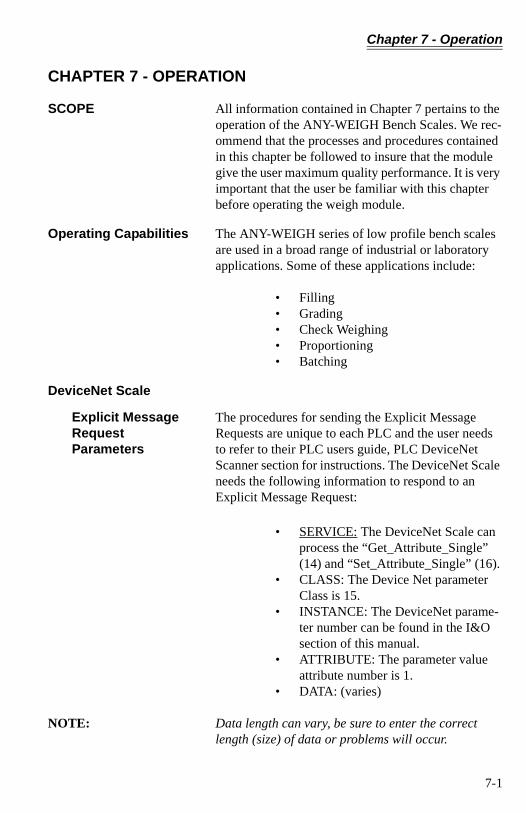
SCOPE All information contained in Chapter 7 pertains to the operation of the ANY-WEIGH Bench Scales. We rec-ommend that the processes and procedures contained in this chapter be followed to insure that the module give the user maximum quality performance. It is very important that the user be familiar with this chapter before operating the weigh module.
Operating Capabilities The ANY-WEIGH series of low profile bench scales are used in a broad range of industrial or laboratory applications. Some of these applications include:
• Filling• Grading• Check Weighing• Proportioning• Batching
DeviceNet Scale
Explicit Message Request Parameters
The procedures for sending the Explicit Message Requests are unique to each PLC and the user needs to refer to their PLC users guide, PLC DeviceNet Scanner section for instructions. The DeviceNet Scale needs the following information to respond to an Explicit Message Request:
• SERVICE: The DeviceNet Scale can process the “Get_Attribute_Single” (14) and “Set_Attribute_Single” (16).
• CLASS: The Device Net parameter Class is 15.
• INSTANCE: The DeviceNet parame-ter number can be found in the I&O section of this manual.
• ATTRIBUTE: The parameter value attribute number is 1.
• DATA: (varies)
NOTE: Data length can vary, be sure to enter the correct length (size) of data or problems will occur.
7-1

Any-Weigh™ Series Bench Scales
NOTE: Order of bytes must be least significant first.
Monitoring Weight Readings from RS NetWorx
Step 1. On the PC open RS NetWorx. Step 2. Browse the Network. Step 3. Double click on the Node Icon of the
weigh module you want to monitor. For example: Node 36. The DeviceNet Weigh Module Dialog Box appears for Node 36.
Step 4. Click on the Parameters Tab. Step 5. All the parameters including the weights
are displayed. Step 6. The NET, GROSS, and TARE weights are
now being monitored.
Network Status (DS1)
Scale Status (DS2)
STATE LED INDICATION
NOT POW-ERED/NOT ON LINE
OFF DEVICE IS NOT ON LINE1. NO POWER APPLIED2. Dup_MAC_ID TEST NOT COMPLETE
OPERATIONAL AND ON-LINE
GREEN ON LINE NORMAL CONDITION WITH CONNECTIONS ESTABLISHED.
OPERATION AND ON LINE NOT CON-NECTED
FLASHING GREEN
ON LINE NORMAL CONDITION NO CONNECTIONSDup_MAC_ID PASSED & ON LINE, NO CONNECTIONS TO OTHER NODES.
CRITICAL FAULT OR LINK FAILURE
RED UNRECOVERABLE FAULT (MAY NEED REPLACING)FAILED COMMUICATIONS (DUPLICATE Mac ID OR BUS OFF)
Table 7-1: NETWORK STATUS (DS1)
STATE LED INDICATION
NOT POWERED/NOT ON LINE
OFF DEVICE IS NOT ON LINE1. NO POWER APPLIED
OPERATIONAL GREEN NORM CONDITION
Table 7-2: SCALE STATUS
7-2
Chapter 7 - Operation
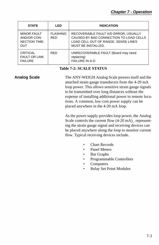
Analog Scale The ANY-WEIGH Analog Scale powers itself and the attached strain gauge transducers from the 4-20 mA loop power. This allows sensitive strain gauge signals to be transmitted over long distances without the expense of installing additional power to remote loca-tions. A common, low-cost power supply can be placed anywhere in the 4-20 mA loop.
As the power supply provides loop power, the Analog Scale controls the current flow (4-20 mA)_ represent-ing the strain gauge signal and receiving devices can be placed anywhere along the loop to monitor current flow. Typical receiving devices include.
• Chart Records• Panel Meters• Bar Graphs• Programmable Controllers• Computers• Relay Set Point Modules
MINOR FAULTAND/OR CON-NECTION TIME-OUT
FLASHINGRED
RECOVERABLE FAULT A/D ERROR, USUALLY CAUSED BY BAD CONNECTION TO LOAD CELLSLOAD CELL OUT OF RANGE. SENSE LINES MUST BE INSTALLED.
CRITICALFAULT OR LINKFAILURE
RED UNRECOVERABLE FAULT (Board may need replacing)FAILURE IN A-D
STATE LED INDICATION
Table 7-2: SCALE STATUS
7-3

Any-Weigh™ Series Bench Scales
7-4
Chapter 8 - Troubleshooting
CHAPTER 8 - TROUBLESHOOTING
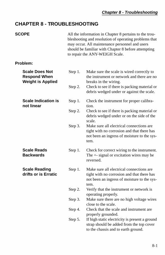
SCOPE All the information in Chapter 8 pertains to the trou-bleshooting and resolution of operating problems that may occur. All maintenance personnel and users should be familiar with Chapter 8 before attempting to repair the ANY-WEIGH Scale.
Problem:
Scale Does Not Respond When Weight is Applied
Step 1. Make sure the scale is wired correctly to the instrument or network and there are no breaks in the wiring.
Step 2. Check to see if there is packing material or debris wedged under or against the scale.
Scale Indication is not linear
Step 1. Check the instrument for proper calibra-tion.
Step 2. Check to see if there is packing material or debris wedged under or on the side of the scale.
Step 3. Make sure all electrical connections are tight with no corrosion and that there has not been an ingress of moisture to the sys-tem.
Scale Reads Backwards
Step 1. Check for correct wiring to the instrument. The +- signal or excitation wires may be reversed.
Scale Reading drifts or is Erratic
Step 1. Make sure all electrical connections are tight with no corrosion and that there has not been an ingress of moisture to the sys-tem.
Step 2. Verify that the instrument or network is operating properly.
Step 3. Make sure there are no high voltage wires close to the scale.
Step 4. Check that the scale and instrument are properly grounded.
Step 5. If high static electricity is present a ground strap should be added from the top cover to the chassis and to earth ground.
8-1

Any-Weigh™ Series Bench Scales
DeviceNet Scale: Module LED does not Come Back on When Performing Calibration with The Button
Step 1. Indicates a hardware problem. Contact Hardy Technical Support for assistance.
DeviceNet Scale: Module LED is Flashing Red
Step 1. Check all the connections to be sure they are securely fastened.
Step 2. Reinstall if any appear to be loose.
Analog Scale: Malfunction, No Output
Step 1. Check voltage at + & - loop connections. The voltage should read 15 VDC to 50 VDC.
Step 2. Check all the connections to be sure they are securely fastened.
Step 3. If the voltage is correct and all connections are securely fastened, contact Hardy Tech-nical Support Department.
Analog Scale: No Change in Input
Step 1. Check to see if the Load Cell signal output is below the original setting. If the signal level returned by the Load Cells is below the previous dead load setting, measure approximately 2.3 mA between the loop + and - terminals.
Step 2. Check to see if the Load Cell signal output is above the original setting. If the signal level returned by the Load Cell is above the previous Span setting, measure approximately 23 mA between the loop + and - terminals.
Analog Scale: Output Drifts
Step 1. Check all the load cell connections to be sure they are securely fastened.
Step 2. Check the Power Supply to make sure there is a constant voltage output.
Service and Repair (All Models)
For Service and Repairs, contact your local Hardy Representative.
Before returning any product to Hardy Instruments Inc., please contact the Hardy Service Center for a return authorization number. Please have the scale
8-2
Chapter 8 - Troubleshooting
model number and serial number and a brief descrip-tion of the problem ready when you call.
Technical SupportHardy Instruments, Inc.9440 Carroll Park Drive, Suite 150San Diego, CA 92121 Web-Site: http://www.hardyinst.comUS Customers Only: 800-821-5831Outside the US: 858-278-2900 FAX: (858) 278-6700
8-3

Any-Weigh™ Series Bench Scales
8-4
Index
Index
AAbout Calibration of the DeviceNet, Analog and Universal Bench Scales 6-1Accessing the DIP Switch 4-2Adjust the Leveling Feet 3-3Analog Scale 1-2, 3-5, 7-3
Malfunction, No Output 8-2No Change in Input 8-2Output Drifts 8-2
Analog Scale Specifications 2-2Analog Scales HI SBA Series 6-4ANY-WEIGH Analog Scale 7-3Attribute 7-1
BBases 1-1Baud Rate 4-1Baud Rates 2-2Browse the Network 6-2Build-Up of Debris 3-1
CC2 Second Generation Calibration 6-1C2® Calibration from a Personal Computer 6-2C2® Electronic Calibration 1-1Cal HI Command 6-4Cal LO Weight 6-3Calibration Controls 6-4Calibration Procedures 6-5Chassis Ground Attchment Point 4-2Class 7-1Coarse (ZERO) 6-4Command Interface 5-4Configuring the Baud Rate 4-2Configuring the DeviceNet Node Address 4-2
Any-Weigh™ Series Bench Scales
Covers 1-1Creep 2-1
DDATA 7-1Deadloads 6-4Description 1-1DeviceNet Communication Configuration 4-1DeviceNet Connection Wiring Diagram 3-4DeviceNet Manager 6-2, 6-3DeviceNet Network Cable 3-4DeviceNet Node Address 4-2DeviceNet Pin Out Diagram 3-4DeviceNet Scale 3-4, 7-1
Module LED is Flashing Red 8-2DeviceNet Scale Specifications 2-2DeviceNet Scales HI SBD Series 6-1DeviceNet™ Network 1-2DeviceNet™ Scale 1-2DIP Switch (S1) Configuration 4-1DIP Switch Location 4-1Drawing # 0588-0097 3-5
EEarth Ground 4-2Electrical Specifications 2-1Examples Using the Command Interface 5-5Explicit Message Request Parameters 7-1
FFine (ZERO) 6-4Format of Commands (4 byte Input Data) 5-4
GGross Weight in lbs 5-5
Index
HHardy Any-Weigh™ Bench Scales 1-1
II/O Slave Messaging 2-2Input Power 2-2Input Resistance 2-1Inputs 2-2Instance 7-1Introduction 1-1
LLevel the Corners 3-1Leveling Feet 3-2Leveling the Scale 3-1Linearity 2-2Loop Power 2-2Loop Wires 3-5Lower Frame Assembly 1-1
MMaterial Substitution 6-1Maximum Overload 2-1Mechanical Dimensions 2-3Micro DeviceNet Connector 3-4Minimum Power Supply Voltage 3-5Module LED 6-2Module Status (DS2) 7-2Monitoring Weight Readings 7-2
NNetwork Status (DS1) 7-2Node Address 4-1Node Icon 6-3, 7-2Non-Linearity 2-2Non-Volatile RAM 5-1
Any-Weigh™ Series Bench Scales
OOperating Capabilities 7-1Output Resistance 2-1Outputs 2-2
PParameters 5-1Preinstallation Precautions 3-1
RRated Output 2-1Recommended DC or AC Excitation Voltage 3-3Resolution 2-2Response Time 2-3
SSafe Load Limi 2-1Saving to Non-Volatile Ram 5-1Scale does not respond when weight is applied 8-1Scale indication is not linear 8-1Scale Reading drifts or is Erratic 8-1Scale Reads Backwards 8-1Sensitivity 2-3Service 7-1Service and Repair 8-2Setpoints 5-6Shock Load and Corner Overload Protection 1-1Span 6-4Span Weight 6-3Spirit Level 3-1
TTemperature Coefficient 2-2, 2-3Temperature Effect 2-1Temperature Range 2-1, 2-2, 2-3Test Weight Calibration (Hard Cal) 6-1Test Weight Calibration Procedures 6-3
Index
THE BUTTON® 6-2The Stainless Steel Top Cover 1-1Total Error 2-1Type 2-2
UUniversal Scale Electrical Connections 3-3Universal Scale Interface 1-1Universal Scale Specifications 2-1Universal Scales HI SBU Series 6-1Unpacking 3-1Update Rate 2-2
WWAVERSAVER® 1-1Wire the Scale Cable 3-3

Any-Weigh™ Series Bench Scales
Related Documents