2005 BRAKES Anti-Lock Brake System With Electronic Brake Force Distribution (EBD) - Diagnostics - RAV4 HOW TO PROCEED WITH TROUBLESHOOTING Troubleshoot in accordance with the following procedures. 2005 Toyota RAV4 2005 BRAKES Anti-Lock Brake System With Electronic Brake Force Distribution (EBD) - Diagnostics - RAV4

Antilock Brakes
Dec 24, 2015
manual
Welcome message from author
This document is posted to help you gain knowledge. Please leave a comment to let me know what you think about it! Share it to your friends and learn new things together.
Transcript

2005 BRAKES
Anti-Lock Brake System With Electronic Brake Force Distribution (EBD) - Diagnostics - RAV4
HOW TO PROCEED WITH TROUBLESHOOTING
Troubleshoot in accordance with the following procedures.
2005 Toyota RAV4
2005 BRAKES Anti-Lock Brake System With Electronic Brake Force Distribution (EBD) - Diagnostics - RAV4
2005 Toyota RAV4
2005 BRAKES Anti-Lock Brake System With Electronic Brake Force Distribution (EBD) - Diagnostics - RAV4
Microsoft
Tuesday, July 21, 2009 10:28:25 AM Page 1 © 2005 Mitchell Repair Information Company, LLC.
Microsoft
Tuesday, July 21, 2009 10:28:33 AM Page 1 © 2005 Mitchell Repair Information Company, LLC.

Fig. 1: Troubleshooting Chart Courtesy of TOYOTA MOTOR SALES, U.S.A., INC.
Fail-safe function:
2005 Toyota RAV4
2005 BRAKES Anti-Lock Brake System With Electronic Brake Force Distribution (EBD) - Diagnostics - RAV4
Microsoft
Tuesday, July 21, 2009 10:28:25 AM Page 2 © 2005 Mitchell Repair Information Company, LLC.

When a failure occurs in the ABS system, the ABS warning light lights up and the ABS operation is prohibited. In addition to this, when the failure which disables the EBD operation occurs, the brake warning light lights up and the EBD operation is prohibited as well.
CUSTOMER PROBLEM ANALYSIS CHECK
Fig. 2: Customer Problem Analysis Chart Courtesy of TOYOTA MOTOR SALES, U.S.A., INC.
PRE-CHECK
1. DIAGNOSIS SYSTEM
a. Release the parking brake lever.
2005 Toyota RAV4
2005 BRAKES Anti-Lock Brake System With Electronic Brake Force Distribution (EBD) - Diagnostics - RAV4
Microsoft
Tuesday, July 21, 2009 10:28:25 AM Page 3 © 2005 Mitchell Repair Information Company, LLC.

b. Check the indicator.
When the ignition switch is turned ON, check that the ABS warning light and BRAKE warning light illuminate for approximately 3 seconds.
Fig. 3: Locating ABS Warning Light & Brake Warning Light Courtesy of TOYOTA MOTOR SALES, U.S.A., INC.
HINT:
When the parking brake is applied or the level of the brake fluid is low, the BRAKE warning light lights up.
If the indicator check result is not normal, proceed to the troubleshooting for the ABS warning light circuit or BRAKE warning light circuit (see ABS WARNING LIGHT CIRCUIT or BRAKE WARNING LIGHT CIRCUIT).
Check the ABS1 fuse, ABS2 fuse and ABS actuator assembly.
c. When not using hand-held tester:
Check the DTC.
1. Using SST, connect terminals TC and CG of the DLC3.
2005 Toyota RAV4
2005 BRAKES Anti-Lock Brake System With Electronic Brake Force Distribution (EBD) - Diagnostics - RAV4
Microsoft
Tuesday, July 21, 2009 10:28:25 AM Page 4 © 2005 Mitchell Repair Information Company, LLC.
SST 09843-18040
2. Turn the ignition switch ON.
3. Read the DTC from the ABS warning light on the combination meter.
HINT:
If no code appears, inspect the diagnostic circuit or ABS warning light circuit (see TC TERMINAL CIRCUIT or ABS WARNING LIGHT CIRCUIT).
Fig. 4: Connecting Terminals TC & CG Of DLC3 Courtesy of TOYOTA MOTOR SALES, U.S.A., INC.
As an example, the blinking patterns of normal code and codes 11 and 21 are shown on the left.
2005 Toyota RAV4
2005 BRAKES Anti-Lock Brake System With Electronic Brake Force Distribution (EBD) - Diagnostics - RAV4
Microsoft
Tuesday, July 21, 2009 10:28:25 AM Page 5 © 2005 Mitchell Repair Information Company, LLC.

Fig. 5: Blinking Patterns Of Normal Code Courtesy of TOYOTA MOTOR SALES, U.S.A., INC.
4. Codes are detailed in the code table on DIAGNOSTIC TROUBLE CODE CHART.
2005 Toyota RAV4
2005 BRAKES Anti-Lock Brake System With Electronic Brake Force Distribution (EBD) - Diagnostics - RAV4
Microsoft
Tuesday, July 21, 2009 10:28:25 AM Page 6 © 2005 Mitchell Repair Information Company, LLC.
5. After completing the check, disconnect terminals TC and CG from the DLC3, and turn the display off.
If 2 or more malfunctions are indicated at the same time, the lowest numbered DTC will be displayed first.
d. When using the hand-held tester:
Check the DTC.
1. Connect the hand-held tester to the DLC3.
Fig. 6: Connecting Hand-Held Tester To DLC3 Courtesy of TOYOTA MOTOR SALES, U.S.A., INC.
2. Turn the ignition switch ON.
3. Read the DTC by following the prompts on the tester screen.
Please refer to the hand-held tester operator's manual for further details.
2005 Toyota RAV4
2005 BRAKES Anti-Lock Brake System With Electronic Brake Force Distribution (EBD) - Diagnostics - RAV4
Microsoft
Tuesday, July 21, 2009 10:28:25 AM Page 7 © 2005 Mitchell Repair Information Company, LLC.

e. When not using the hand-held tester:
Clear the DTC.
1. Using SST, connect terminals TC and CG of the DLC3.
SST 09843-18040
2. Turn the ignition switch ON.
Fig. 7: Connecting Terminals TC & CG Of DLC3 Courtesy of TOYOTA MOTOR SALES, U.S.A., INC.
3. Clear the DTC stored in the ECU by depressing the brake pedal 8 or more times within 5 seconds.
4. Check that the warning light shows the normal code.
2005 Toyota RAV4
2005 BRAKES Anti-Lock Brake System With Electronic Brake Force Distribution (EBD) - Diagnostics - RAV4
Microsoft
Tuesday, July 21, 2009 10:28:25 AM Page 8 © 2005 Mitchell Repair Information Company, LLC.
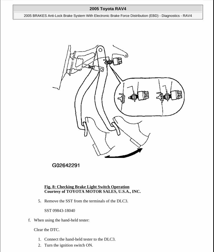
Fig. 8: Checking Brake Light Switch Operation Courtesy of TOYOTA MOTOR SALES, U.S.A., INC.
5. Remove the SST from the terminals of the DLC3.
SST 09843-18040
f. When using the hand-held tester:
Clear the DTC.
1. Connect the hand-held tester to the DLC3.
2. Turn the ignition switch ON.
2005 Toyota RAV4
2005 BRAKES Anti-Lock Brake System With Electronic Brake Force Distribution (EBD) - Diagnostics - RAV4
Microsoft
Tuesday, July 21, 2009 10:28:25 AM Page 9 © 2005 Mitchell Repair Information Company, LLC.

3. Operate the hand-held tester to erase the codes (see hand-held tester operator's manual).
Fig. 9: Connecting Hand-Held Tester To DLC3 Courtesy of TOYOTA MOTOR SALES, U.S.A., INC.
2. FREEZE FRAME DATA
HINT:
Whenever a DTC is detected or the ABS operates, the skid control ECU stores the current vehicle (sensor) state as freeze frame data.
The skid control ECU stores the number of times (maximum 31) the ignition switch has been turned OFF to ON since the last time ABS was activated. However, if the vehicle is not moved or driven at low speed (7 km/h (4.3 mph) or less), or if a DTC is detected, the skid control ECU will not count the number since then.
Freeze frame data at the time the ABS operates:
The skid control ECU stores and updates data whenever the ABS system operates.
When the ECU stores data at the time a DTC is detected, the data stored when the ABS operated is
2005 Toyota RAV4
2005 BRAKES Anti-Lock Brake System With Electronic Brake Force Distribution (EBD) - Diagnostics - RAV4
Microsoft
Tuesday, July 21, 2009 10:28:25 AM Page 10 © 2005 Mitchell Repair Information Company, LLC.

erased.
Freeze frame data at the time a DTC is detected:
When the skid control ECU stores data at the time a DTC is detected, no updates will be performed until the data is cleared.
a. Connect the hand-held tester to the DLC3.
b. Turn the ignition switch to the ON position.
c. From the display on the tester, select the "FREEZE FRAME DATA".
FREEZE FRAME DATA REFERENCE
3. SPEED SENSOR SIGNAL
a. When not using hand-held tester:
Check the speed sensor signal.
1. Turn the ignition switch OFF.
2. Using SST, connect terminals TS and CG of the DLC3.
SST 09843-18040
Hand-held Tester Display Measurement Item Reference Value (1)
G (BACK & FORTH) Back and forth G (only for 4WD) -1.5-1.5VEHICLE SPD Vehicle speed Speed indication of a meterSPD GRADE Vehicle speed grade (only for
2WD)-1.5-1.5
STOP LIGHT SW Stop light switch signal Stop light switch ON: ON, OFF: OFF
#IG ON Numbers of operations of ignition switch ON after memorizing freeze
frame data
0-31
(1) If no conditions are specifically stated for "Idling", it means the shift lever is at N or P position, the A/C switch is OFF and all accessory switches are OFF.
2005 Toyota RAV4
2005 BRAKES Anti-Lock Brake System With Electronic Brake Force Distribution (EBD) - Diagnostics - RAV4
Microsoft
Tuesday, July 21, 2009 10:28:25 AM Page 11 © 2005 Mitchell Repair Information Company, LLC.

Fig. 10: Connecting Terminals TC & CG Of DLC3 Courtesy of TOYOTA MOTOR SALES, U.S.A., INC.
3. Start the engine.
4. Check that the ABS warning light blinks.
HINT:
If the ABS warning light does not blink, inspect the ABS warning light circuit (see ABS WARNING LIGHT CIRCUIT).
5. Drive the vehicle straight forward.
HINT:
Drive the vehicle at more than 45 km/h (28 mph) for several seconds.
6. Stop the vehicle.
7. Remove the SST from the terminals of the DLC3.
2005 Toyota RAV4
2005 BRAKES Anti-Lock Brake System With Electronic Brake Force Distribution (EBD) - Diagnostics - RAV4
Microsoft
Tuesday, July 21, 2009 10:28:25 AM Page 12 © 2005 Mitchell Repair Information Company, LLC.

SST 09843-18040
8. Read the number of blinks of the ABS warning light.
HINT:
Refer to DTC list, see Fig. 13.
If each sensor is normal, the normal code is output (a cycle of 0.25 seconds ON and 0.25 seconds OFF is repeated).
If 2 or more malfunctions are indicated at the same time, the lowest numbered code will be displayed first.
Fig. 11: Blinking Patterns Of Normal Code Courtesy of TOYOTA MOTOR SALES, U.S.A., INC.
9. After doing the check, disconnect the SST from terminals TS, TC and CG of the DLC3, and turn the ignition switch OFF.
SST 09843-18040
b. When using hand-held tester:
Check the speed sensor signal.
1. Connect the hand-held tester to the DLC3.
2005 Toyota RAV4
2005 BRAKES Anti-Lock Brake System With Electronic Brake Force Distribution (EBD) - Diagnostics - RAV4
Microsoft
Tuesday, July 21, 2009 10:28:25 AM Page 13 © 2005 Mitchell Repair Information Company, LLC.

Fig. 12: Connecting Hand-Held Tester To DLC3 Courtesy of TOYOTA MOTOR SALES, U.S.A., INC.
2. Follow previous steps (3) to (6).
3. Read the DTC by following the prompts on the tester screen.
Refer to the hand-held tester operator's manual for further details.
DTC Of Speed Sensor Check Function:
2005 Toyota RAV4
2005 BRAKES Anti-Lock Brake System With Electronic Brake Force Distribution (EBD) - Diagnostics - RAV4
Microsoft
Tuesday, July 21, 2009 10:28:25 AM Page 14 © 2005 Mitchell Repair Information Company, LLC.

Fig. 13: Speed Sensor DTC Table Courtesy of TOYOTA MOTOR SALES, U.S.A., INC.
4. 4WD:
DECELERATION SENSOR CHECK
a. Connect 3 dry batteries of 1.5 V in series.
b. Connect terminal VGS to the batteries' positive (+) terminal, and terminal GGND to the batteries' negative (-) terminal. Apply about 4.5 V to terminals VGS and GGND.
c. Check the output voltage of terminal GL1.
VOLTAGE SPECIFICATION
HINT:
If the sensor is tilted a lot, it may show the wrong value.
NOTE: Do not apply voltage of 6 V or more to terminals VGS and GGND.
Condition Standard ValueHorizontal About 2.3 VLean forward 0.4 to about 2.3 VLean rearward About 2.3 to 4.1 V
2005 Toyota RAV4
2005 BRAKES Anti-Lock Brake System With Electronic Brake Force Distribution (EBD) - Diagnostics - RAV4
Microsoft
Tuesday, July 21, 2009 10:28:25 AM Page 15 © 2005 Mitchell Repair Information Company, LLC.

If dropped, the sensor should be replaced with a new one.
The sensor removed from the vehicle should not be placed upside down.
2005 Toyota RAV4
2005 BRAKES Anti-Lock Brake System With Electronic Brake Force Distribution (EBD) - Diagnostics - RAV4
Microsoft
Tuesday, July 21, 2009 10:28:25 AM Page 16 © 2005 Mitchell Repair Information Company, LLC.

Fig. 14: Inspecting Deceleration SensorCourtesy of TOYOTA MOTOR SALES, U.S.A., INC.
DIAGNOSTIC TROUBLE CODE CHART
HINT:
Using SST 09843-18040, connect the terminals TC and CG of the DLC3.
If any abnormalities are not found when inspecting the parts, inspect the ECU.
If a malfunction code is displayed during the DTC check, check the circuit listed in the code. For details of each code, refer to the "See Page" under the respective "DTC No." in the following DTC chart.
2005 Toyota RAV4
2005 BRAKES Anti-Lock Brake System With Electronic Brake Force Distribution (EBD) - Diagnostics - RAV4
Microsoft
Tuesday, July 21, 2009 10:28:25 AM Page 17 © 2005 Mitchell Repair Information Company, LLC.

2005 Toyota RAV4
2005 BRAKES Anti-Lock Brake System With Electronic Brake Force Distribution (EBD) - Diagnostics - RAV4
Microsoft
Tuesday, July 21, 2009 10:28:25 AM Page 18 © 2005 Mitchell Repair Information Company, LLC.

Fig. 15: Diagnostic Trouble Code Chart Courtesy of TOYOTA MOTOR SALES, U.S.A., INC.
HINT:
There is a case where the hand-held tester cannot be used when the ABS warning light is always ON.
DIAGNOSTIC TROUBLE CODES (DTC) LIST
PARTS LOCATION
DTC DescriptionDTC C0200/31, C0200/32, C0200/33, C0200/34, C0200/35, C0200/36, C0200/38, C1239/39
Speed Sensor Circuit
DTC C0226/21, C0226/22, C0226/23, C0256/24
ABS Solenoid Valve Circuit
DTC C0273/13, C0274/14 ABS Motor Relay CircuitDTC C0278/11, C0279/12 ABS Solenoid Relay CircuitDTC C1241/41 IG Power Source CircuitDTC C1243/43, C1245/45 Malfunction in Deceleration Sensor (Only for 4WD)DTC C1244/44 Deceleration Sensor Circuit (Only for 4WD)DTC C1249/49 Stop Light Switch CircuitDTC C1251/51 ABS Pump Motor LockDTC C1337/37 Tires of Different Size (Only for 2WD)
2005 Toyota RAV4
2005 BRAKES Anti-Lock Brake System With Electronic Brake Force Distribution (EBD) - Diagnostics - RAV4
Microsoft
Tuesday, July 21, 2009 10:28:25 AM Page 19 © 2005 Mitchell Repair Information Company, LLC.

Fig. 16: Locating Anti-Lock Brake System Components Courtesy of TOYOTA MOTOR SALES, U.S.A., INC.
TERMINALS OF ECU
2005 Toyota RAV4
2005 BRAKES Anti-Lock Brake System With Electronic Brake Force Distribution (EBD) - Diagnostics - RAV4
Microsoft
Tuesday, July 21, 2009 10:28:25 AM Page 20 © 2005 Mitchell Repair Information Company, LLC.

Fig. 17: Identifying ECM connector Terminals Courtesy of TOYOTA MOTOR SALES, U.S.A., INC.
ECM CONNECTOR TERMINALS VOLTAGE SPECIFICATION
Symbols (Terminal No.)Wiring Color
ConditionSpecified
Condition+BS (A4-1) - GND (A4-2, 24) R-Y - W-B Always 11 to 14 V
GL1 (A4-4) - GGND (A4-7) (1) W-B Ignition switch
ONVehicle is placed in flat
area2.0 to 3.0 V
FL+ (A4-9) - FL- (A4-8) R-GIgnition switch
ONSlowly turn left front
wheelAC generation
STP (A4-10) - GND (A4-2,24)
G-W - W-BStop light switch ON 10 to 14 VStop light switch OFF Below 1.0 V
RL+(A4-11)-RL-(A4-12) G-RIgnition switch
ONSlowly turn left rear
wheelAC generation
WA (A4-13) - GND (A4-2, 24) R-Y - W-B
Ignition switch ON
ABS warning light ON 10 to 14V
Ignition switch ON ABS warning light OFF Below 2.0 V
D/G(A4-14)-GND (A4-2, 24)
W-W-B Ignition switch ON 10 to 14V
TS (A4 - 15) - GND (A4-2, 24)
P-L-W-B Ignition switch ON 10 to 14V
TC (A4-16) - GND (A4-2, 24) P-B-W-B Ignition switch ON 10 to 14 V
Ignition switch
2005 Toyota RAV4
2005 BRAKES Anti-Lock Brake System With Electronic Brake Force Distribution (EBD) - Diagnostics - RAV4
Microsoft
Tuesday, July 21, 2009 10:28:25 AM Page 21 © 2005 Mitchell Repair Information Company, LLC.

PROBLEM SYMPTOMS TABLE
If a normal code is displayed during the DTC check although the problem still occurs, check the circuits for each problem symptom in the order given in Fig. 18 and proceed to the relevant troubleshooting information.
PKB (A4-18) - GND (A4-2, 24)
R-B-W-BON Parking switch ON Below 1.0 V
Ignition switch ON Parking switch OFF 10 to 14V
+BM (A4-23) - GND (A4-2,24)
W-R - W-B Always 11 to 14 V
IG1 (A4-25) - GND (A4-2, 24)
R-L-W-B Ignition switch ON 10 to 14 V
VGS (A4-28) - GGND (A4-7)* R-B Ignition switch ON 4.5 to 5.5 V
FR+ (A4-31) - FR- (A4-30) B-WIgnition switch
ONSlowly turn right front
wheelAC generation
RR+ (A4-33) - RR- (A4-34) Y-BR Ignition switch ON
Slowly turn right rear wheel
AC generation
BRL (A4-32) - GND (A4-2,24) R-W-B
Ignition switch ON Brake warning light ON 10 to 14V
Ignition switch ON
Brake warning light OFF Below 2.0 V
(1) Only for 4WD.
NOTE: When replacing ABS ECU, sensor or etc., turn the ignition switch OFF.
2005 Toyota RAV4
2005 BRAKES Anti-Lock Brake System With Electronic Brake Force Distribution (EBD) - Diagnostics - RAV4
Microsoft
Tuesday, July 21, 2009 10:28:25 AM Page 22 © 2005 Mitchell Repair Information Company, LLC.

Fig. 18: Problem Symptoms Table Courtesy of TOYOTA MOTOR SALES, U.S.A., INC.
CIRCUIT INSPECTION
DTC C0200/31, C0200/32, C0200/33, C0200/34, C0200/35, C0200/36, C0200/38, C1239/39: SPEED SENSOR CIRCUIT
CIRCUIT DESCRIPTION
The speed sensor detects the wheel speed and sends appropriate signals to the ECU. These signals are used to control the ABS system. Each of the front and rear rotors has 48 serrations.
When the rotors rotate, magnetic field emitted by the permanent magnet in the speed sensor generates an AC voltage. Since the frequency of this AC voltage changes in direct proportion to the speed of the rotor, the frequency is used by the ECU to detect the speed of each wheel.
2005 Toyota RAV4
2005 BRAKES Anti-Lock Brake System With Electronic Brake Force Distribution (EBD) - Diagnostics - RAV4
Microsoft
Tuesday, July 21, 2009 10:28:25 AM Page 23 © 2005 Mitchell Repair Information Company, LLC.
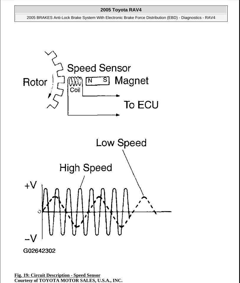
Fig. 19: Circuit Description - Speed Sensor Courtesy of TOYOTA MOTOR SALES, U.S.A., INC.
2005 Toyota RAV4
2005 BRAKES Anti-Lock Brake System With Electronic Brake Force Distribution (EBD) - Diagnostics - RAV4
Microsoft
Tuesday, July 21, 2009 10:28:25 AM Page 24 © 2005 Mitchell Repair Information Company, LLC.

Fig. 20: DTC Detection Condition Table Courtesy of TOYOTA MOTOR SALES, U.S.A., INC.
HINT:
DTC No. C0200/31 and C1235/35 are for the right front speed sensor.
DTC No. C0205/32 and C1236/36 are for the left front speed sensor.
DTC No. C0210/33 and C1238/38 are for the right rear speed sensor.
DTC No. C0215/34 and C1239/39 are for the left rear speed sensor.
WIRING DIAGRAM
2005 Toyota RAV4
2005 BRAKES Anti-Lock Brake System With Electronic Brake Force Distribution (EBD) - Diagnostics - RAV4
Microsoft
Tuesday, July 21, 2009 10:28:25 AM Page 25 © 2005 Mitchell Repair Information Company, LLC.

Fig. 21: Wiring Diagram - Speed Sensor Courtesy of TOYOTA MOTOR SALES, U.S.A., INC.
INSPECTION PROCEDURE
HINT:
Start the inspection from step 1 when using the hand-held tester. Start from 2 when not using the hand-held tester.
1. Check output value of speed sensor.
PREPARATION:
a. Connect the hand-held tester to the DLC3.
b. Turn the ignition switch ON and push the hand-held tester main switch ON.
c. Select the DATA LIST mode on the hand-held tester.
2005 Toyota RAV4
2005 BRAKES Anti-Lock Brake System With Electronic Brake Force Distribution (EBD) - Diagnostics - RAV4
Microsoft
Tuesday, July 21, 2009 10:28:25 AM Page 26 © 2005 Mitchell Repair Information Company, LLC.

CHECK:
Check that there is no difference between the speed value output from the speed sensor and displayed on the hand-held tester and the speed value displayed on the speedometer when driving the vehicle.
OK:
There is almost no difference between the displayed speed values.
HINT:
There is tolerance of ohm 10 % in the speedometer indication.
OK: Check and replace ABS actuator assembly.
NG: Go To Next Step.
2. Check speed sensor.
Front speed sensor:
PREPARATION:
a. Remove the front fender liner.
b. Make sure that there is no looseness at the connector lock part and connecting part of the connector.
c. Disconnect the speed sensor connector.
CHECK:
Measure the resistance between terminals 1 and 2 of the speed sensor connector.
2005 Toyota RAV4
2005 BRAKES Anti-Lock Brake System With Electronic Brake Force Distribution (EBD) - Diagnostics - RAV4
Microsoft
Tuesday, July 21, 2009 10:28:25 AM Page 27 © 2005 Mitchell Repair Information Company, LLC.
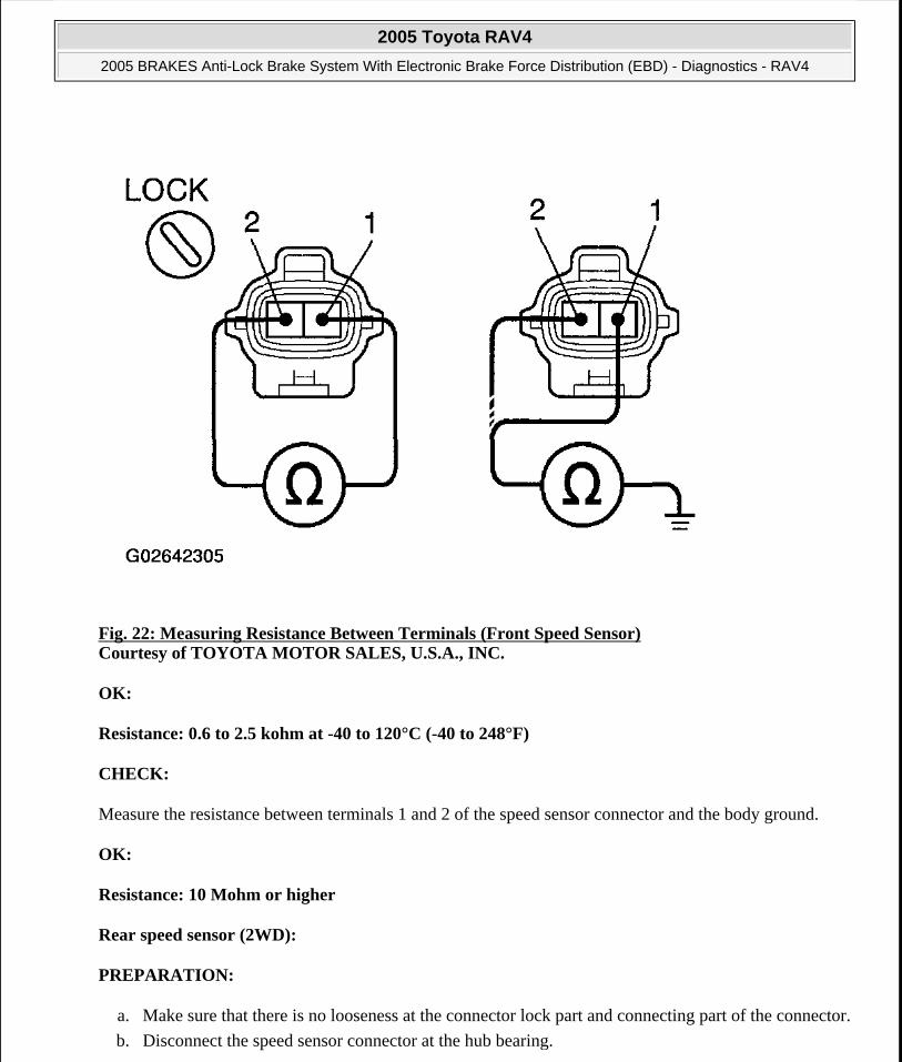
Fig. 22: Measuring Resistance Between Terminals (Front Speed Sensor) Courtesy of TOYOTA MOTOR SALES, U.S.A., INC.
OK:
Resistance: 0.6 to 2.5 kohm at -40 to 120°C (-40 to 248°F)
CHECK:
Measure the resistance between terminals 1 and 2 of the speed sensor connector and the body ground.
OK:
Resistance: 10 Mohm or higher
Rear speed sensor (2WD):
PREPARATION:
a. Make sure that there is no looseness at the connector lock part and connecting part of the connector.
b. Disconnect the speed sensor connector at the hub bearing.
2005 Toyota RAV4
2005 BRAKES Anti-Lock Brake System With Electronic Brake Force Distribution (EBD) - Diagnostics - RAV4
Microsoft
Tuesday, July 21, 2009 10:28:25 AM Page 28 © 2005 Mitchell Repair Information Company, LLC.

CHECK:
Measure the resistance between terminals 1 and 2 of the speed sensor connector.
Fig. 23: Measuring Resistance Between Terminals (Rear Speed Sensor) Courtesy of TOYOTA MOTOR SALES, U.S.A., INC.
OK:
Resistance: 0.8 to 1.9 kohm at -40 to 120°C (-40 to 248°F)
CHECK:
Measure the resistance between terminals 1 and 2 of the speed sensor connector and the body ground.
OK:
Resistance: 1 Mohm or higher
2005 Toyota RAV4
2005 BRAKES Anti-Lock Brake System With Electronic Brake Force Distribution (EBD) - Diagnostics - RAV4
Microsoft
Tuesday, July 21, 2009 10:28:25 AM Page 29 © 2005 Mitchell Repair Information Company, LLC.

Rear speed sensor (4WD):
PREPARATION:
a. Make sure that there is no looseness at the connector lock part and connecting part of the connector.
b. Disconnect the speed sensor connector at the hub bearing.
CHECK:
Measure the resistance between terminals 1 and 2 of the speed sensor connector.
OK:
Resistance: 0.65 to 1.8 kohm at -40 to 120°C (-40 to 248°F)
Fig. 24: Measuring Resistance Between Terminals (Front Speed Sensor)(4WD) Courtesy of TOYOTA MOTOR SALES, U.S.A., INC.
CHECK:
Measure the resistance between terminals 1 and 2 of the speed sensor connector and the body ground.
2005 Toyota RAV4
2005 BRAKES Anti-Lock Brake System With Electronic Brake Force Distribution (EBD) - Diagnostics - RAV4
Microsoft
Tuesday, July 21, 2009 10:28:25 AM Page 30 © 2005 Mitchell Repair Information Company, LLC.

OK:
Resistance: 1 Mohm or higher
Rear speed sensor sub-wire harness (2WD):
PREPARATION:
a. Remove the seat cushion and seatback.
b. Make sure that there is no looseness at the connector lock part and connecting part of the connector.
c. Disconnect the speed sensor connector inside the vehicle.
CHECK:
a. Measure the resistance between terminal 1 of connector 1 and terminal 2 of connector 2.
Fig. 25: Measuring Resistance Between Terminals (Rear Speed Sensor Sub-Wire Harness)(2WD) Courtesy of TOYOTA MOTOR SALES, U.S.A., INC.
b. Measure the resistance between terminal 2 of connector 1 and terminal 1 of connector 2.
2005 Toyota RAV4
2005 BRAKES Anti-Lock Brake System With Electronic Brake Force Distribution (EBD) - Diagnostics - RAV4
Microsoft
Tuesday, July 21, 2009 10:28:25 AM Page 31 © 2005 Mitchell Repair Information Company, LLC.
OK:
Resistance: Below 1 ohm
CHECK:
Measure the resistance between terminals 1 and 2 of the speed sensor connector 1 and the body ground.
OK:
Resistance: 10 Mohm or higher
NG: Replace speed sensor or sub-wire harness.
OK: Go To Next Step.
3. Check for open and short circuit in harness and connector between each speed sensor and ABS ECU (See HOW TO USE THE DIAGNOSTIC CHART AND INSPECTION PROCEDURE ).
NG: Repair or replace harness and connector.
OK: Go To Next Step.
4. Check speed sensor installation.
CHECK:
Check the speed sensor installation.
OK:
FRONT (2WD, 4WD), Rear (4WD):
The installation bolt is tightened properly or there is no clearance between the sensor and steering knuckle or rear axle carrier.
Torque: 8.0 N.m (82 kgf.cm, 71 in.lbf).
Rear (2WD):
There is no clearance between the sensor and rear axle carrier
NOTE: Check the speed sensor signal last (see PRE-CHECK).
2005 Toyota RAV4
2005 BRAKES Anti-Lock Brake System With Electronic Brake Force Distribution (EBD) - Diagnostics - RAV4
Microsoft
Tuesday, July 21, 2009 10:28:25 AM Page 32 © 2005 Mitchell Repair Information Company, LLC.

2005 Toyota RAV4
2005 BRAKES Anti-Lock Brake System With Electronic Brake Force Distribution (EBD) - Diagnostics - RAV4
Microsoft
Tuesday, July 21, 2009 10:28:25 AM Page 33 © 2005 Mitchell Repair Information Company, LLC.

Fig. 26: Installing Speed Sensors Courtesy of TOYOTA MOTOR SALES, U.S.A., INC.
NG: Replace*1 and repair*2 speed sensor.
*1 : Front (2WD, 4WD), rear (4WD)
Remove the sensor and reinstall it. Then do not replace the sensor when it is as shown in Fig. 26 at the time of reinstallation.
Clean the attached part, such as the tip of sensor, and reinstall the sensor.
*2 : Rear (2WD)
Replace the speed sensor.
OK: Go To Next Step.
5. Check speed sensor and sensor rotor serrations.
Reference: INSPECTION USING OSCILLOSCOPE
PREPARATION:
a. Remove the ABS ECU with the connector still connected.
b. Connect an oscilloscope to terminals FR+, FL+, RR+ or RL+ and GND of the ABS ECU connector.
CHECK:
Drive the vehicle at about 20 km/h (13 mph), and check the signal waveform.
HINT:
Check that foreign objects are stuck on the sensor tip in case of noise occurrence.
NOTE: Check the speed sensor signal last (see PRE-CHECK).
2005 Toyota RAV4
2005 BRAKES Anti-Lock Brake System With Electronic Brake Force Distribution (EBD) - Diagnostics - RAV4
Microsoft
Tuesday, July 21, 2009 10:28:25 AM Page 34 © 2005 Mitchell Repair Information Company, LLC.

Fig. 27: Speed Sensor & Sensor Rotor Serrations Signal Waveform Courtesy of TOYOTA MOTOR SALES, U.S.A., INC.
OK: Check and replace ABS actuator assembly.
NG: Go To Next Step.
6. Check sensor rotor and sensor tip.
Front:
PREPARATION:
Remove the front drive shaft (see REMOVAL ).
CHECK:
Check the sensor rotor serrations.
OK:
No scratches, missing teeth or foreign objects.
2005 Toyota RAV4
2005 BRAKES Anti-Lock Brake System With Electronic Brake Force Distribution (EBD) - Diagnostics - RAV4
Microsoft
Tuesday, July 21, 2009 10:28:25 AM Page 35 © 2005 Mitchell Repair Information Company, LLC.

HINT:
If foreign objects are stuck on the rotor, remove them.
Fig. 28: Checking Speed Sensor Rotor Serrations (Front) Courtesy of TOYOTA MOTOR SALES, U.S.A., INC.
PREPARATION:
Remove the front speed sensor (see REMOVAL ).
CHECK:
2005 Toyota RAV4
2005 BRAKES Anti-Lock Brake System With Electronic Brake Force Distribution (EBD) - Diagnostics - RAV4
Microsoft
Tuesday, July 21, 2009 10:28:25 AM Page 36 © 2005 Mitchell Repair Information Company, LLC.

Check the sensor tip.
OK:
No scratches or foreign objects on the sensor tip.
HINT:
If foreign objects are stuck on the sensor tip, remove them before reuse. Check the rotor for the presence of foreign objects and remove them if they are present.
Rear (2WD):
PREPARATION:
Remove the rear axle hub (see REMOVAL ).
CHECK:
Check the sensor rotor serrations.
OK:
No scratches, missing teeth or foreign objects.
HINT:
If foreign objects are stuck on the rotor, remove them.
2005 Toyota RAV4
2005 BRAKES Anti-Lock Brake System With Electronic Brake Force Distribution (EBD) - Diagnostics - RAV4
Microsoft
Tuesday, July 21, 2009 10:28:25 AM Page 37 © 2005 Mitchell Repair Information Company, LLC.

Fig. 29: Checking Sensor Rotor Serrations (Rear 2WD) Courtesy of TOYOTA MOTOR SALES, U.S.A., INC.
CHECK:
Check the sensor tip.
2005 Toyota RAV4
2005 BRAKES Anti-Lock Brake System With Electronic Brake Force Distribution (EBD) - Diagnostics - RAV4
Microsoft
Tuesday, July 21, 2009 10:28:26 AM Page 38 © 2005 Mitchell Repair Information Company, LLC.

OK:
No scratches or foreign objects on the sensor tip.
Rear (4WD):
PREPARATION:
Remove the rear drive shaft (see REMOVAL ).
CHECK:
Check the sensor rotor serrations.
OK:
No scratches, missing teeth or foreign objects.
HINT:
If foreign objects are stuck on the rotor, remove them.
2005 Toyota RAV4
2005 BRAKES Anti-Lock Brake System With Electronic Brake Force Distribution (EBD) - Diagnostics - RAV4
Microsoft
Tuesday, July 21, 2009 10:28:26 AM Page 39 © 2005 Mitchell Repair Information Company, LLC.

Fig. 30: Checking Sensor Rotor Serrations (Rear 4WD) Courtesy of TOYOTA MOTOR SALES, U.S.A., INC.
PREPARATION:
Remove the rear speed sensor (see REMOVAL ).
CHECK:
Check the sensor tip.
OK:
No scratches or foreign objects on the sensor tip.
2005 Toyota RAV4
2005 BRAKES Anti-Lock Brake System With Electronic Brake Force Distribution (EBD) - Diagnostics - RAV4
Microsoft
Tuesday, July 21, 2009 10:28:26 AM Page 40 © 2005 Mitchell Repair Information Company, LLC.

HINT:
If foreign objects are stuck on the sensor tip, remove them before reuse. Check the rotor for the presence of foreign objects and remove them if they are present.
NG: Replace sensor rotor or speed sensor.
OK: Check and replace ABS actuator assembly.
DTC C0226/21, C0226/22, C0226/23, C0256/24: ABS SOLENOID VALVE CIRCUIT
CIRCUIT DESCRIPTION
The ABS solenoid valve turns on when signals are sent from the ECU and controls the pressure operating the wheel cylinders, thus the braking force is controlled.
Fig. 31: DTC Trouble Detection Condition - ABS Solenoid Valve Circuit Courtesy of TOYOTA MOTOR SALES, U.S.A., INC.
HINT:
DTC No. C0226/21 is for right front solenoid valve.
DTC No. C0236/22 is for left front solenoid valve.
DTC No. C0246/23 is for right rear solenoid valve.
DTC No. C0256/24 is for left rear solenoid valve.
WIRING DIAGRAM
NOTE: Check the speed sensor signal last (see PRE-CHECK).
2005 Toyota RAV4
2005 BRAKES Anti-Lock Brake System With Electronic Brake Force Distribution (EBD) - Diagnostics - RAV4
Microsoft
Tuesday, July 21, 2009 10:28:26 AM Page 41 © 2005 Mitchell Repair Information Company, LLC.

Fig. 32: Wiring Diagram - ABS Solenoid Valve Courtesy of TOYOTA MOTOR SALES, U.S.A., INC.
INSPECTION PROCEDURE
1. Check DTC once more.
PREPARATION:
a. Clear the DTC (see PRE-CHECK).
b. Turn the ignition switch OFF.
CHECK:
Turn the ignition switch ON and check that the same DTC is stored in the memory.
NO: No problem
YES: Replace ABS actuator assembly.
DTC C0273/13, C0274/14: ABS MOTOR RELAY CIRCUIT
CIRCUIT DESCRIPTION
The ABS motor relay supplies power to the ABS pump motor. While the ABS is activated, the ECU switches the ABS motor relay ON and operates the ABS pump motor.
2005 Toyota RAV4
2005 BRAKES Anti-Lock Brake System With Electronic Brake Force Distribution (EBD) - Diagnostics - RAV4
Microsoft
Tuesday, July 21, 2009 10:28:26 AM Page 42 © 2005 Mitchell Repair Information Company, LLC.
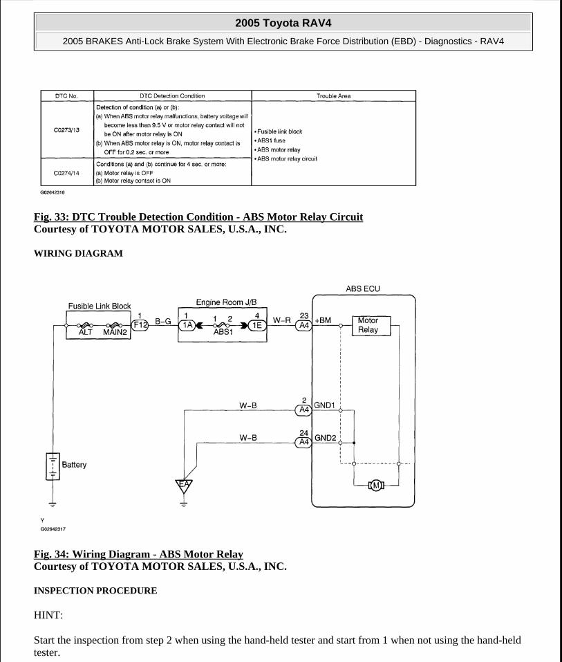
Fig. 33: DTC Trouble Detection Condition - ABS Motor Relay Circuit Courtesy of TOYOTA MOTOR SALES, U.S.A., INC.
WIRING DIAGRAM
Fig. 34: Wiring Diagram - ABS Motor Relay Courtesy of TOYOTA MOTOR SALES, U.S.A., INC.
INSPECTION PROCEDURE
HINT:
Start the inspection from step 2 when using the hand-held tester and start from 1 when not using the hand-held tester.
2005 Toyota RAV4
2005 BRAKES Anti-Lock Brake System With Electronic Brake Force Distribution (EBD) - Diagnostics - RAV4
Microsoft
Tuesday, July 21, 2009 10:28:26 AM Page 43 © 2005 Mitchell Repair Information Company, LLC.

1. Check voltage between terminals +BM (23) and GND (2, 24) of ABS ECU connector.
PREPARATION:
Disconnect the ABS ECU connector.
CHECK:
Measure the voltage between terminals 23 and 2 or 24 of the ABS ECU connector.
OK:
Voltage: 11 to 14 V
Fig. 35: Measuring Voltage Between Terminals ABS ECU Connector Courtesy of TOYOTA MOTOR SALES, U.S.A., INC.
NG: Check and repair harness and connector.
2005 Toyota RAV4
2005 BRAKES Anti-Lock Brake System With Electronic Brake Force Distribution (EBD) - Diagnostics - RAV4
Microsoft
Tuesday, July 21, 2009 10:28:26 AM Page 44 © 2005 Mitchell Repair Information Company, LLC.

OK: Go To Next Step.
2. Check ABS motor relay operation.
PREPARATION:
a. Connect the hand-held tester to the DLC3.
b. Turn the ignition switch ON and push the hand-held tester main switch ON.
c. Select the ACTIVE TEST mode on the hand-held tester.
CHECK:
Check the operation sound of the ABS motor individually when operating it using the hand-held tester.
OK:
The operation sound of the ABS motor should be heard.
NG: Check and replace ABS actuator assembly.
OK: If same code is still output after DTC is deleted, check contact condition of each connection. If connection is normal, ECU may be defective.
DTC C0278/11, C0279/12: ABS SOLENOID RELAY CIRCUIT
CIRCUIT DESCRIPTION
This relay supplies power to each ABS solenoid. After the ignition switch is turned ON, if the initial check is OK, the relay turns on.
Fig. 36: DTC Trouble Detection Condition - ABS Solenoid Relay Circuit Courtesy of TOYOTA MOTOR SALES, U.S.A., INC.
WIRING DIAGRAM
2005 Toyota RAV4
2005 BRAKES Anti-Lock Brake System With Electronic Brake Force Distribution (EBD) - Diagnostics - RAV4
Microsoft
Tuesday, July 21, 2009 10:28:26 AM Page 45 © 2005 Mitchell Repair Information Company, LLC.

Fig. 37: Wiring Diagram - ABS Solenoid Relay Courtesy of TOYOTA MOTOR SALES, U.S.A., INC.
INSPECTION PROCEDURE
HINT:
Start the inspection from step 2 when using the hand-held tester and start from 1 when not using the hand-held tester.
1. Check voltage between terminals +BS (1) and GND (2, 24) of ABS ECU connector.
PREPARATION:
Disconnect the ABS ECU connector.
CHECK:
Measure the voltage between terminals 1 and 2 or 24 of the ABS ECU connector.
OK:
Voltage: 11 to 14 V
2005 Toyota RAV4
2005 BRAKES Anti-Lock Brake System With Electronic Brake Force Distribution (EBD) - Diagnostics - RAV4
Microsoft
Tuesday, July 21, 2009 10:28:26 AM Page 46 © 2005 Mitchell Repair Information Company, LLC.

Fig. 38: Measuring Voltage Between Terminals Of The ABS ECU Connector Courtesy of TOYOTA MOTOR SALES, U.S.A., INC.
NG: Check and repair harness and connector.
OK: Go To Next Step.
2. Check ABS solenoid relay operation.
PREPARATION:
a. Connect the hand-held tester to the DLC3.
b. Turn the ignition switch ON and press the hand-held tester main switch ON.
c. Select the ACTIVE TEST mode on the hand-held tester.
CHECK:
Check the operation sound of the ABS solenoid relay when operating it using the hand-held tester.
OK:
2005 Toyota RAV4
2005 BRAKES Anti-Lock Brake System With Electronic Brake Force Distribution (EBD) - Diagnostics - RAV4
Microsoft
Tuesday, July 21, 2009 10:28:26 AM Page 47 © 2005 Mitchell Repair Information Company, LLC.
The operation sound of the ABS solenoid relay should be heard.
NG: Check and replace ABS actuator assembly.
OK: If same code is still output after DTC is deleted, check contact condition of each connection. If connection is normal, ECU may be defective.
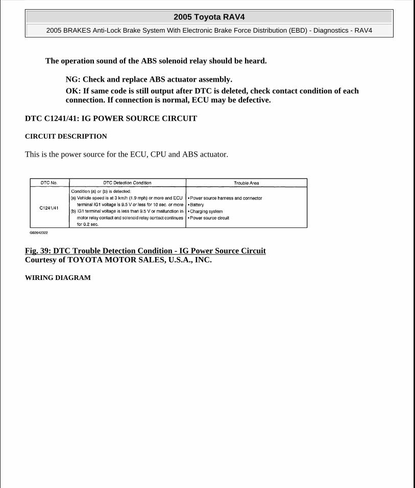
DTC C1241/41: IG POWER SOURCE CIRCUIT
CIRCUIT DESCRIPTION
This is the power source for the ECU, CPU and ABS actuator.
Fig. 39: DTC Trouble Detection Condition - IG Power Source Circuit Courtesy of TOYOTA MOTOR SALES, U.S.A., INC.
WIRING DIAGRAM
2005 Toyota RAV4
2005 BRAKES Anti-Lock Brake System With Electronic Brake Force Distribution (EBD) - Diagnostics - RAV4
Microsoft
Tuesday, July 21, 2009 10:28:26 AM Page 48 © 2005 Mitchell Repair Information Company, LLC.

Fig. 40: Wiring Diagram - IG Power Source Courtesy of TOYOTA MOTOR SALES, U.S.A., INC.
INSPECTION PROCEDURE
1. Check ECU-IG fuse.
PREPARATION:
Remove the ECU-IG fuse from the driver side J/B.
CHECK:
Check the resistance.
OK:
Resistance: Below 1 ohm
2005 Toyota RAV4
2005 BRAKES Anti-Lock Brake System With Electronic Brake Force Distribution (EBD) - Diagnostics - RAV4
Microsoft
Tuesday, July 21, 2009 10:28:26 AM Page 49 © 2005 Mitchell Repair Information Company, LLC.

Fig. 41: Identifying ECU-IG Fuse (Driver Side Junction/Box) Courtesy of TOYOTA MOTOR SALES, U.S.A., INC.
NG: Replace ECU-IG fuse.
OK: Go To Next Step.
2. Check battery voltage.
2005 Toyota RAV4
2005 BRAKES Anti-Lock Brake System With Electronic Brake Force Distribution (EBD) - Diagnostics - RAV4
Microsoft
Tuesday, July 21, 2009 10:28:26 AM Page 50 © 2005 Mitchell Repair Information Company, LLC.

OK:
Voltage: 10 to 14 V
NG: Check and repair charging system (See HOW TO USE THE DIAGNOSTIC CHART AND INSPECTION PROCEDURE ).
OK: Go To Next Step.
3. Check voltage of IG power source.
When using the hand-held tester:
PREPARATION:
a. Connect the hand-held tester to the DLC3.
b. Turn the ignition switch ON and press the hand-held tester main switch ON.
c. Select the DATA LIST mode on the hand-held tester.
CHECK:
Check the voltage condition output from the ECU and displayed on the hand-held tester.
OK:
"Normal" is displayed.
When not using the hand-held tester:
PREPARATION:
Disconnect the ABS ECU connector.
CHECK:
a. Turn the ignition switch ON.
b. Measure the voltage between terminals 25 and 2 or 24 of the ABS ECU connector.
OK:
Voltage: 10 to 14 V
2005 Toyota RAV4
2005 BRAKES Anti-Lock Brake System With Electronic Brake Force Distribution (EBD) - Diagnostics - RAV4
Microsoft
Tuesday, July 21, 2009 10:28:26 AM Page 51 © 2005 Mitchell Repair Information Company, LLC.

Fig. 42: Measuring Voltage Between Terminals Of The ABS ECU Connector Courtesy of TOYOTA MOTOR SALES, U.S.A., INC.
OK: Check or replace ABS actuator assembly.
NG: Go To Next Step.
4. Check resistance between terminals GND (2, 24) of ABS ECU connector and body ground.
CHECK:
Measure the resistance between terminals 2 and 24 of the ABS ECU connector and the body ground.
OK:
Resistance: Below 1 ohm
2005 Toyota RAV4
2005 BRAKES Anti-Lock Brake System With Electronic Brake Force Distribution (EBD) - Diagnostics - RAV4
Microsoft
Tuesday, July 21, 2009 10:28:26 AM Page 52 © 2005 Mitchell Repair Information Company, LLC.

Fig. 43: Measuring Resistance Between Terminals Of The ABS ECU Connector Courtesy of TOYOTA MOTOR SALES, U.S.A., INC.
NG: Repair or replace harness and connector.
OK: Check for open circuit in harness and connector between ABS ECU and ECU-IG fuse (See HOW TO USE THE DIAGNOSTIC CHART AND INSPECTION PROCEDURE ).
DTC C1243/43, C1245/45: MALFUNCTION IN DECELERATION SENSOR (ONLY FOR 4WD)
CIRCUIT DESCRIPTION
2005 Toyota RAV4
2005 BRAKES Anti-Lock Brake System With Electronic Brake Force Distribution (EBD) - Diagnostics - RAV4
Microsoft
Tuesday, July 21, 2009 10:28:26 AM Page 53 © 2005 Mitchell Repair Information Company, LLC.
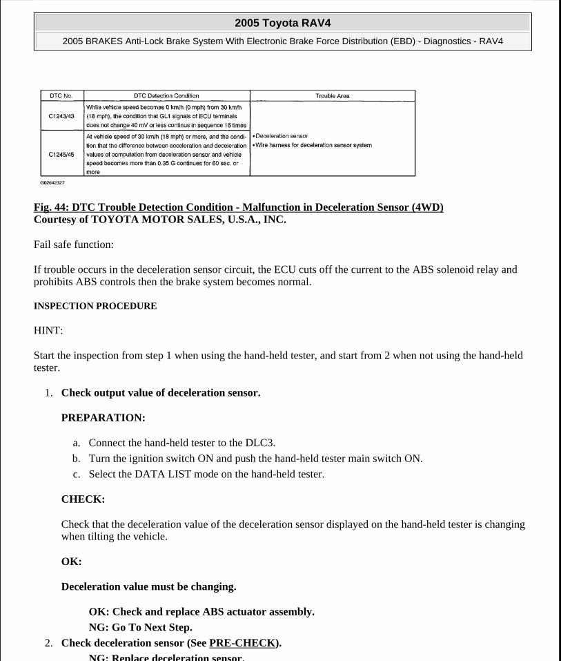
Fig. 44: DTC Trouble Detection Condition - Malfunction in Deceleration Sensor (4WD) Courtesy of TOYOTA MOTOR SALES, U.S.A., INC.
Fail safe function:
If trouble occurs in the deceleration sensor circuit, the ECU cuts off the current to the ABS solenoid relay and prohibits ABS controls then the brake system becomes normal.
INSPECTION PROCEDURE
HINT:
Start the inspection from step 1 when using the hand-held tester, and start from 2 when not using the hand-held tester.
1. Check output value of deceleration sensor.
PREPARATION:
a. Connect the hand-held tester to the DLC3.
b. Turn the ignition switch ON and push the hand-held tester main switch ON.
c. Select the DATA LIST mode on the hand-held tester.
CHECK:
Check that the deceleration value of the deceleration sensor displayed on the hand-held tester is changing when tilting the vehicle.
OK:
Deceleration value must be changing.
OK: Check and replace ABS actuator assembly.
NG: Go To Next Step.
2. Check deceleration sensor (See PRE-CHECK).
NG: Replace deceleration sensor.
2005 Toyota RAV4
2005 BRAKES Anti-Lock Brake System With Electronic Brake Force Distribution (EBD) - Diagnostics - RAV4
Microsoft
Tuesday, July 21, 2009 10:28:26 AM Page 54 © 2005 Mitchell Repair Information Company, LLC.

OK: Go To Next Step.
3. Check for open or short circuit in harness and connector between deceleration sensor and ABS ECU (See HOW TO USE THE DIAGNOSTIC CHART AND INSPECTION PROCEDURE ).
NG: Repair or replace harness and connector.
OK: Check and replace ABS actuator assembly.
DTC C1244/44: DECELERATION SENSOR CIRCUIT (ONLY FOR 4WD)
CIRCUIT DESCRIPTION
This sensor detects deceleration of the vehicle. The sensor signal is used in ABS control. If the sensor functions abnormally, the ABS warning light turns on.
Fig. 45: DTC Trouble Detection Condition - Deceleration Sensor Circuit (4WD) Courtesy of TOYOTA MOTOR SALES, U.S.A., INC.
Fail-safe function:
If trouble occurs in the deceleration sensor circuit, the ECU cuts off the current to the ABS solenoid relay and prohibits ABS controls and then the brake system becomes normal.
WIRING DIAGRAM
2005 Toyota RAV4
2005 BRAKES Anti-Lock Brake System With Electronic Brake Force Distribution (EBD) - Diagnostics - RAV4
Microsoft
Tuesday, July 21, 2009 10:28:26 AM Page 55 © 2005 Mitchell Repair Information Company, LLC.
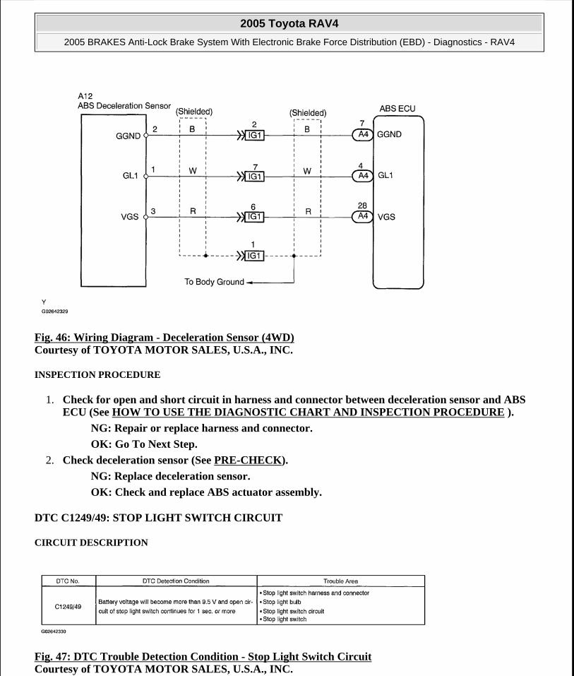
Fig. 46: Wiring Diagram - Deceleration Sensor (4WD) Courtesy of TOYOTA MOTOR SALES, U.S.A., INC.
INSPECTION PROCEDURE
1. Check for open and short circuit in harness and connector between deceleration sensor and ABS ECU (See HOW TO USE THE DIAGNOSTIC CHART AND INSPECTION PROCEDURE ).
NG: Repair or replace harness and connector.
OK: Go To Next Step.
2. Check deceleration sensor (See PRE-CHECK).
NG: Replace deceleration sensor.
OK: Check and replace ABS actuator assembly.
DTC C1249/49: STOP LIGHT SWITCH CIRCUIT
CIRCUIT DESCRIPTION
Fig. 47: DTC Trouble Detection Condition - Stop Light Switch Circuit Courtesy of TOYOTA MOTOR SALES, U.S.A., INC.
2005 Toyota RAV4
2005 BRAKES Anti-Lock Brake System With Electronic Brake Force Distribution (EBD) - Diagnostics - RAV4
Microsoft
Tuesday, July 21, 2009 10:28:26 AM Page 56 © 2005 Mitchell Repair Information Company, LLC.

WIRING DIAGRAM
Fig. 48: Wiring Diagram - Stop Light Switch Courtesy of TOYOTA MOTOR SALES, U.S.A., INC.
INSPECTION PROCEDURE
1. Check operation of stop light.
CHECK:
Check that stop light turns ON when the brake pedal is depressed and turns OFF when the brake pedal is released.
NG: Repair stop light circuit (See STOP LIGHT SYSTEM ).
OK: Go To Next Step.
2. Check voltage between terminal STP (10) of ABS ECU connector and body ground.
PREPARATION:
2005 Toyota RAV4
2005 BRAKES Anti-Lock Brake System With Electronic Brake Force Distribution (EBD) - Diagnostics - RAV4
Microsoft
Tuesday, July 21, 2009 10:28:26 AM Page 57 © 2005 Mitchell Repair Information Company, LLC.

Disconnect the ABS ECU connector.
CHECK:
Measure the voltage between terminal 10 of the ABS ECU connector and the body ground when the brake pedal is depressed.
OK:
Voltage: 10 to 14 V
Fig. 49: Measuring Voltage Between Terminal Of The ABS ECU Connector & Body Ground Courtesy of TOYOTA MOTOR SALES, U.S.A., INC.
OK: Check and replace ABS actuator assembly.
NG: Go To Next Step.
3. Check for open circuit in harness and connector between ABS ECU and stop light switch (See HOW TO USE THE DIAGNOSTIC CHART AND INSPECTION PROCEDURE ).
NG: Repair or replace harness and connector or stop light bulb.
OK: Check and replace ABS actuator assembly.
DTC C1251/51: ABS PUMP MOTOR LOCK
2005 Toyota RAV4
2005 BRAKES Anti-Lock Brake System With Electronic Brake Force Distribution (EBD) - Diagnostics - RAV4
Microsoft
Tuesday, July 21, 2009 10:28:26 AM Page 58 © 2005 Mitchell Repair Information Company, LLC.

CIRCUIT DESCRIPTION
Fig. 50: DTC Trouble Detection Condition - ABS Pump Motor Lock Courtesy of TOYOTA MOTOR SALES, U.S.A., INC.
WIRING DIAGRAM
Fig. 51: Wiring Diagram - ABS Pump Motor Lock Courtesy of TOYOTA MOTOR SALES, U.S.A., INC.
INSPECTION PROCEDURE
1. Check ABS pump motor operation.
2005 Toyota RAV4
2005 BRAKES Anti-Lock Brake System With Electronic Brake Force Distribution (EBD) - Diagnostics - RAV4
Microsoft
Tuesday, July 21, 2009 10:28:26 AM Page 59 © 2005 Mitchell Repair Information Company, LLC.

PREPARATION:
a. Connect the hand-held tester to the DLC3.
b. Turn the ignition switch ON and press the hand-held tester main switch ON.
c. Select the ACTIVE TEST mode on the hand-held tester.
CHECK:
Check the operation sound of the ABS pump motor when operating it using the hand-held tester.
OK:
The operation sound of the ABS pump motor should be heard.
NG: Check and replace ABS actuator assembly.
OK: Proceed to next circuit inspection shown in problem symptoms chart (See PROBLEM SYMPTOMS TABLE).
DTC C1337/37: TIRES OF DIFFERENT SIZE (ONLY FOR 2WD)
CIRCUIT DESCRIPTION
CIRCUIT DESCRIPTION
INSPECTION PROCEDURE
1. Check tire size.
NG: Replace tires so that all 4 tires are same in size.
OK: Go To Next Step.
2. Check sensor rotor (See CIRCUIT INSPECTION).
NG: Replace speed sensor rotor.
OK: Go To Next Step.
3. Check speed sensor (See CIRCUIT INSPECTION).
NG: Replace speed sensor.
OK: Go To Next Step.
4. Check for open and short circuit in harness and connector between speed sensor and ABS ECU (See HOW TO USE THE DIAGNOSTIC CHART AND INSPECTION PROCEDURE ).
NG: Repair or replace harness and connector.
OK: Check and replace ABS actuator assembly.
DTC No. DTC Detection ConditionTrouble
Area
C1337/37Driving at more than 20 km/h (12 mph) for more than 20 sec. with 1 or 2 tires of
different size 3 times continuouslyTire size
2005 Toyota RAV4
2005 BRAKES Anti-Lock Brake System With Electronic Brake Force Distribution (EBD) - Diagnostics - RAV4
Microsoft
Tuesday, July 21, 2009 10:28:26 AM Page 60 © 2005 Mitchell Repair Information Company, LLC.

DIAGNOSTIC TROUBLE CODES ALWAYS ON ABS ECU MALFUNCTION OR POWER SOURCE VOLTAGE UP
CIRCUIT DESCRIPTION
Fig. 52: DTC Trouble Detection Condition - Trouble Codes Always ON Courtesy of TOYOTA MOTOR SALES, U.S.A., INC.
INSPECTION PROCEDURE
1. Check that ABS ECU connectors are securely connected to ABS ECU.
NO: Connect connector to ABS ECU.
YES: Go To Next Step.
2. Is DTC output?
Check DTC on PRE-CHECK.
YES: Repair circuit indicated by code output.
NO: Go To Next Step.
3. Check voltage between terminals IG1 (25) and GND (2, 24) of ABS ECU connector.
PREPARATION:
Disconnect the ABS ECU connector.
CHECK:
a. Turn the ignition switch ON.
b. Measure the voltage between terminals 25 and 2 or 24 of the ABS ECU connector.
OK:
Voltage: 10 to 14 V
2005 Toyota RAV4
2005 BRAKES Anti-Lock Brake System With Electronic Brake Force Distribution (EBD) - Diagnostics - RAV4
Microsoft
Tuesday, July 21, 2009 10:28:26 AM Page 61 © 2005 Mitchell Repair Information Company, LLC.

Fig. 53: Measuring Voltage Between Terminals Of The ABS ECU Connector Courtesy of TOYOTA MOTOR SALES, U.S.A., INC.
NG: Check for open and short circuit in harness and connector between ECU-IG fuse and ABS ECU (See HOW TO USE THE DIAGNOSTIC CHART AND INSPECTION PROCEDURE ).
OK: Go To Next Step.
4. Check ABS warning light.
When using the hand-held tester:
PREPARATION:
a. Connect the hand-held tester to the DLC3.
b. Turn the ignition switch ON and press the hand-held tester main switch ON.
c. Select the ACTIVE TEST mode on the hand-held tester.
CHECK:
2005 Toyota RAV4
2005 BRAKES Anti-Lock Brake System With Electronic Brake Force Distribution (EBD) - Diagnostics - RAV4
Microsoft
Tuesday, July 21, 2009 10:28:26 AM Page 62 © 2005 Mitchell Repair Information Company, LLC.

Check that the ABS warning light can be turned ON and OFF on the combination meter using the hand-held tester.
OK:
The ABS warning light turns off.
When not using the hand-held tester:
PREPARATION:
Disconnect the ABS ECU connector.
CHECK:
a. Using a service wire, connect terminals WA (13) and GND (2 or 24) of the ABS ECU connector.
b. Turn the ignition switch ON.
OK:
The ABS warning light turns off.
2005 Toyota RAV4
2005 BRAKES Anti-Lock Brake System With Electronic Brake Force Distribution (EBD) - Diagnostics - RAV4
Microsoft
Tuesday, July 21, 2009 10:28:26 AM Page 63 © 2005 Mitchell Repair Information Company, LLC.

Fig. 54: Connecting Terminals Of The ABS ECU Connector & Body Ground Courtesy of TOYOTA MOTOR SALES, U.S.A., INC.
OK: Check and replace ABS actuator assembly.
NG: Check for open or short circuit in harness and connector between ABS warning light and ABS ECU, and DLC3 and ABS ECU (See HOW TO USE THE DIAGNOSTIC CHART AND INSPECTION PROCEDURE ).
ABS WARNING LIGHT CIRCUIT
CIRCUIT DESCRIPTION
If the ECU detects trouble, the ABS warning light will be illuminated and ABS control will be prohibited. At this time, the ECU records a DTC in memory.
Connect terminals TC and CG of the DLC3, make the ABS warning light blink and output the DTC.
WIRING DIAGRAM
2005 Toyota RAV4
2005 BRAKES Anti-Lock Brake System With Electronic Brake Force Distribution (EBD) - Diagnostics - RAV4
Microsoft
Tuesday, July 21, 2009 10:28:26 AM Page 64 © 2005 Mitchell Repair Information Company, LLC.

Fig. 55: Wiring Diagram - ABS Warning Light Courtesy of TOYOTA MOTOR SALES, U.S.A., INC.
INSPECTION PROCEDURE
Troubleshoot in accordance with the table below for each trouble symptom.
INSPECTION PROCEDURE
1. Check operation of the ABS warning light.
PREPARATION:
a. Connect the hand-held tester to the DLC3.
ABS warning light does not light up *1ABS warning light remains on *2*1: Start the inspection from step 1 when using the hand-held tester and start from 2 when not using the hand-held tester.*2: After step 3, start the inspection from 4 when using the hand-held tester and start from 5 when not using the hand-held tester.
2005 Toyota RAV4
2005 BRAKES Anti-Lock Brake System With Electronic Brake Force Distribution (EBD) - Diagnostics - RAV4
Microsoft
Tuesday, July 21, 2009 10:28:26 AM Page 65 © 2005 Mitchell Repair Information Company, LLC.

b. Turn the ignition switch ON and push the hand-held tester main switch ON.
c. Select the ACTIVE TEST mode on the hand-held tester.
CHECK:
Check that the ABS warning light can be turned ON and OFF on the combination meter using the hand-held tester.
OK:
The ABS warning light turns off.
OK: Check and replace ABS actuator assembly.
NG: Go To Next Step.
2. Check ABS warning light.
See troubleshooting for the combination meter, refer to PROBLEM SYMPTOMS TABLE .
NG: Replace bulb or combination meter assembly.
OK: Check for open circuit in harness and connector between ECU-IG fuse and ABS warning light (See HOW TO USE THE DIAGNOSTIC CHART AND INSPECTION PROCEDURE ).
3. Check that ECU connector is securely connected to ABS ECU.
NO: Connect connector to ABS ECU.
YES: Go To Next Step.
4. Check operation of the ABS warning light (See step 1).
OK: Check and replace ABS actuator assembly.
NG: Go To Next Step.
5. Is DTC output?
Check DTC on PRE-CHECK.
YES: Repair circuit indicated by code output.
NO: Check for short circuit in harness and connector between ABS warning light and ABS ECU, and DLC3 and ABS ECU (See HOW TO USE THE DIAGNOSTIC CHART AND INSPECTION PROCEDURE ).
BRAKE WARNING LIGHT CIRCUIT
CIRCUIT DESCRIPTION
The BRAKE warning light lights up when the brake fluid is insufficient, the EBD is abnormal, or the parking brake is applied.
2005 Toyota RAV4
2005 BRAKES Anti-Lock Brake System With Electronic Brake Force Distribution (EBD) - Diagnostics - RAV4
Microsoft
Tuesday, July 21, 2009 10:28:26 AM Page 66 © 2005 Mitchell Repair Information Company, LLC.

WIRING DIAGRAM
Fig. 56: Wiring Diagram - Brake Warning Light Courtesy of TOYOTA MOTOR SALES, U.S.A., INC.
INSPECTION PROCEDURE
1. Check parking brake switch circuit (See PROBLEM SYMPTOMS TABLE ).
NG: Repair or replace parking brake switch circuit.
OK: Go To Next Step.
2. Check brake fluid level warning switch circuit (See PROBLEM SYMPTOMS TABLE ).
NG: Repair or replace brake fluid level warning switch circuit.
OK: Go To Next Step.
3. Is DTC output for ABS?
Check DTC on PRE-CHECK.
YES: Repair circuit indicated by output code.
NO: Go To Next Step.
4. Check BRAKE warning light.
See troubleshooting for the combination meter, refer to PROBLEM SYMPTOMS TABLE .
2005 Toyota RAV4
2005 BRAKES Anti-Lock Brake System With Electronic Brake Force Distribution (EBD) - Diagnostics - RAV4
Microsoft
Tuesday, July 21, 2009 10:28:26 AM Page 67 © 2005 Mitchell Repair Information Company, LLC.

NG: Repair or replace combination meter.
OK: Check and replace ABS actuator assembly.
TC TERMINAL CIRCUIT
CIRCUIT DESCRIPTION
Connecting between terminals TC and CG of the DLC3 causes the ECU to display the DTC by flashing the ABS warning light.
WIRING DIAGRAM
Fig. 57: Wiring Diagram - TC Terminal Courtesy of TOYOTA MOTOR SALES, U.S.A., INC.
INSPECTION PROCEDURE
1. Check voltage between terminals TC and CG of DLC3.
CHECK:
a. Turn the ignition switch ON.
b. Measure the voltage between terminals TC and CG of the DLC3.
OK:
Voltage: 10 to 14 V
2005 Toyota RAV4
2005 BRAKES Anti-Lock Brake System With Electronic Brake Force Distribution (EBD) - Diagnostics - RAV4
Microsoft
Tuesday, July 21, 2009 10:28:26 AM Page 68 © 2005 Mitchell Repair Information Company, LLC.

Fig. 58: Measuring Voltage Between Terminals TC & CG Of DLC3 Courtesy of TOYOTA MOTOR SALES, U.S.A., INC.
OK: If ABS warning light does not blink even after TC and CG are connected, ECU may be defective.
NG: Go To Next Step.
2. Check for open and short circuit in harness and connector between ABS ECU and DLC3, and DLC3 and body ground (See HOW TO USE THE DIAGNOSTIC CHART AND INSPECTION PROCEDURE ).
NG: Repair or replace harness and connector.
OK: Check and replace ABS actuator assembly.
TS TERMINAL CIRCUIT
CIRCUIT DESCRIPTION
The sensor check circuit detects abnormalities in the speed sensor signal, which cannot be detected by the DTC check.
Connecting terminals TS and CG of the DLC3 starts the check.
2005 Toyota RAV4
2005 BRAKES Anti-Lock Brake System With Electronic Brake Force Distribution (EBD) - Diagnostics - RAV4
Microsoft
Tuesday, July 21, 2009 10:28:26 AM Page 69 © 2005 Mitchell Repair Information Company, LLC.

WIRING DIAGRAM
Fig. 59: Wiring Diagram - TS Terminal Courtesy of TOYOTA MOTOR SALES, U.S.A., INC.
INSPECTION PROCEDURE
1. Check voltage between terminals TS and CG of DLC3.
CHECK:
a. Turn the ignition switch ON.
b. Measure the voltage between terminals TS and CG of the DLC3.
OK:
Voltage: 10 to 14 V
2005 Toyota RAV4
2005 BRAKES Anti-Lock Brake System With Electronic Brake Force Distribution (EBD) - Diagnostics - RAV4
Microsoft
Tuesday, July 21, 2009 10:28:26 AM Page 70 © 2005 Mitchell Repair Information Company, LLC.

Fig. 60: Measuring Voltage Between Terminals TS & CG Of DLC3 Courtesy of TOYOTA MOTOR SALES, U.S.A., INC.
OK: If ABS warning light does not blink even after TS and CG are connected, ECU may be defective.
NG: Go To Next Step.
2. Check for open and short circuit in harness and connector between ABS ECU and DLC3, and DLC3 and body ground (See HOW TO USE THE DIAGNOSTIC CHART AND INSPECTION PROCEDURE ).
NG: Repair or replace harness and connector.
OK: Check and replace ABS actuator assembly.
CHECK FOR FLUID LEAKAGE
Check for fluid leakage from actuator or hydraulic lines.
2005 Toyota RAV4
2005 BRAKES Anti-Lock Brake System With Electronic Brake Force Distribution (EBD) - Diagnostics - RAV4
Microsoft
Tuesday, July 21, 2009 10:28:26 AM Page 71 © 2005 Mitchell Repair Information Company, LLC.

Fig. 61: Checking For Leaks From Actuator Or Lines Courtesy of TOYOTA MOTOR SALES, U.S.A., INC.
2005 Toyota RAV4
2005 BRAKES Anti-Lock Brake System With Electronic Brake Force Distribution (EBD) - Diagnostics - RAV4
Microsoft
Tuesday, July 21, 2009 10:28:26 AM Page 72 © 2005 Mitchell Repair Information Company, LLC.
Related Documents