BS EN 15129:2009 ICS 91.120.25 NO COPYING WITHOUT BSI PERMISSION EXCEPT AS PERMITTED BY COPYRIGHT LAW BRITISH STANDARD Anti-seismic devices Licensed copy: Imperial College London, Imperial College London, Version correct as of 24/09/2012 15:16, (c) The British Standards Institution 2012

Anti-Seismic Devices
Oct 30, 2014
Anti-Seismic Devices
Welcome message from author
This document is posted to help you gain knowledge. Please leave a comment to let me know what you think about it! Share it to your friends and learn new things together.
Transcript

BS EN 15129:2009
ICS 91.120.25
NO COPYING WITHOUT BSI PERMISSION EXCEPT AS PERMITTED BY COPYRIGHT LAW
BRITISH STANDARD
Anti-seismic devices
Lice
nsed
cop
y: Im
peria
l Col
lege
Lon
don,
Impe
rial C
olle
ge L
ondo
n, V
ersi
on c
orre
ct a
s of
24/
09/2
012
15:1
6, (
c) T
he B
ritis
h S
tand
ards
Inst
itutio
n 20
12

This British Standard was published under the authority of the Standards Policy and Strategy Committee on 31January 2010
© BSI 2010
ISBN 978 0 580 55084 3
Amendments/corrigenda issued since publication
Date Comments
BS EN 15129:2009
National foreword
This British Standard is the UK implementation of EN 15129:2009. The UK participation in its preparation was entrusted to TechnicalCommittee B/522, Structural bearings.A list of organizations represented on this committee can be obtained onrequest to its secretary.This publication does not purport to include all the necessary provisionsof a contract. Users are responsible for its correct application. Compliance with a British Standard cannot confer immunityfrom legal obligations.
Lice
nsed
cop
y: Im
peria
l Col
lege
Lon
don,
Impe
rial C
olle
ge L
ondo
n, V
ersi
on c
orre
ct a
s of
24/
09/2
012
15:1
6, (
c) T
he B
ritis
h S
tand
ards
Inst
itutio
n 20
12

BS EN 15129:2009
EUROPEAN STANDARD
NORME EUROPÉENNE
EUROPÄISCHE NORM
EN 15129
November 2009
ICS 91.120.25
English Version
Anti-seismic devices
Dispositifs anti-sismiques Erdbebenvorrichtungen
This European Standard was approved by CEN on 19 September 2009. CEN members are bound to comply with the CEN/CENELEC Internal Regulations which stipulate the conditions for giving this European Standard the status of a national standard without any alteration. Up-to-date lists and bibliographical references concerning such national standards may be obtained on application to the CEN Management Centre or to any CEN member. This European Standard exists in three official versions (English, French, German). A version in any other language made by translation under the responsibility of a CEN member into its own language and notified to the CEN Management Centre has the same status as the official versions. CEN members are the national standards bodies of Austria, Belgium, Bulgaria, Cyprus, Czech Republic, Denmark, Estonia, Finland, France, Germany, Greece, Hungary, Iceland, Ireland, Italy, Latvia, Lithuania, Luxembourg, Malta, Netherlands, Norway, Poland, Portugal, Romania, Slovakia, Slovenia, Spain, Sweden, Switzerland and United Kingdom.
EUROPEAN COMMITTEE FOR STANDARDIZATION C O M I T É E U R O P É E N D E N O R M A LI S A T I O N EUR OP ÄIS C HES KOM ITEE FÜR NOR M UNG
Management Centre: Avenue Marnix 17, B-1000 Brussels
© 2009 CEN All rights of exploitation in any form and by any means reserved worldwide for CEN national Members.
Ref. No. EN 15129:2009: E
Lice
nsed
cop
y: Im
peria
l Col
lege
Lon
don,
Impe
rial C
olle
ge L
ondo
n, V
ersi
on c
orre
ct a
s of
24/
09/2
012
15:1
6, (
c) T
he B
ritis
h S
tand
ards
Inst
itutio
n 20
12

BS EN 15129:2009EN 15129:2009 (E)
2
Contents Page
Foreword ..............................................................................................................................................................6
1 Scope ......................................................................................................................................................7
2 Normative references ............................................................................................................................7
3 Terms, definitions, symbols and abbreviations .................................................................................83.1 Terms and definitions ...........................................................................................................................83.2 Symbols ............................................................................................................................................... 143.2.1 Latin upper case letters ..................................................................................................................... 143.2.2 Latin lower case letters ...................................................................................................................... 143.2.3 Greek letters ........................................................................................................................................ 143.2.4 Subscripts ........................................................................................................................................... 143.3 Abbreviations ...................................................................................................................................... 153.4 List of devices ..................................................................................................................................... 16
4 General design rules .......................................................................................................................... 184.1 Performance requirements and compliance criteria ....................................................................... 184.1.1 Fundamental requirements ................................................................................................................ 184.1.2 Increased reliability of structural system ......................................................................................... 184.1.3 Functional requirements .................................................................................................................... 194.1.4 Structural and mechanical requirements ......................................................................................... 194.1.5 Compliance criteria............................................................................................................................. 194.2 Action effects on devices .................................................................................................................. 204.2.1 Seismic design situations and seismic combinations of actions ................................................. 204.2.2 Effects of actions ................................................................................................................................ 204.3 Conceptual design of the devices..................................................................................................... 204.3.1 Reliability of the devices’ behaviour................................................................................................. 204.3.2 Capacity design .................................................................................................................................. 204.3.3 Maintenance ........................................................................................................................................ 204.3.4 Modification and replacement of devices ........................................................................................ 214.3.5 Device documentation ....................................................................................................................... 214.4 General properties .............................................................................................................................. 214.4.1 Material properties .............................................................................................................................. 214.4.2 Device properties to be used in the analysis ................................................................................... 214.4.3 Re-centring capability ........................................................................................................................ 224.5 Constitutive laws ................................................................................................................................ 234.6 Validation of anti-seismic devices .................................................................................................... 23
5 Rigid connection devices .................................................................................................................. 245.1 Permanent Connection Devices ........................................................................................................ 245.2 Fuse Restraints ................................................................................................................................... 245.2.1 Performance requirements ................................................................................................................ 245.2.2 Material properties .............................................................................................................................. 245.2.3 Design requirements .......................................................................................................................... 255.2.4 Type Testing ........................................................................................................................................ 255.2.5 Factory production control tests ...................................................................................................... 265.3 Temporary (dynamic) connection devices ....................................................................................... 265.3.1 Functional requirements .................................................................................................................... 265.3.2 Material properties .............................................................................................................................. 275.3.3 Design Requirements ......................................................................................................................... 275.3.4 Type Testing ........................................................................................................................................ 285.3.5 Factory Production Control Tests ..................................................................................................... 30
6 Displacement Dependent Devices .................................................................................................... 30
Lice
nsed
cop
y: Im
peria
l Col
lege
Lon
don,
Impe
rial C
olle
ge L
ondo
n, V
ersi
on c
orre
ct a
s of
24/
09/2
012
15:1
6, (
c) T
he B
ritis
h S
tand
ards
Inst
itutio
n 20
12

BS EN 15129:2009EN 15129:2009 (E)
3
6.1 General ................................................................................................................................................. 306.2 Performance Requirements ............................................................................................................... 316.3 Materials ............................................................................................................................................... 336.3.1 General ................................................................................................................................................. 336.3.2 Elastomer ............................................................................................................................................. 336.3.3 Steel ...................................................................................................................................................... 346.3.4 Other materials (special steel, stainless steel, SMA, visco-elastic polymeric materials) ............ 346.4 Testing .................................................................................................................................................. 346.4.1 General ................................................................................................................................................. 346.4.2 Type tests of materials........................................................................................................................ 346.4.3 Factory production control tests of materials .................................................................................. 366.4.4 Type tests of devices .......................................................................................................................... 376.4.5 Factory production control testing of devices ................................................................................. 38
7 Velocity Dependent Devices .............................................................................................................. 387.1 Functional requirements..................................................................................................................... 387.2 Material properties .............................................................................................................................. 387.2.1 General ................................................................................................................................................. 387.2.2 Materials ............................................................................................................................................... 397.2.3 Active Surfaces .................................................................................................................................... 397.2.4 Viscous Fluid ....................................................................................................................................... 397.3 Design requirements ........................................................................................................................... 397.3.1 General ................................................................................................................................................. 397.3.2 Over velocity ........................................................................................................................................ 407.3.3 Buckling ............................................................................................................................................... 407.4 Testing .................................................................................................................................................. 417.4.1 General ................................................................................................................................................. 417.4.2 Type Testing ........................................................................................................................................ 417.4.3 Factory production control ................................................................................................................ 44
8 Isolators ................................................................................................................................................ 448.1 General Requirements ........................................................................................................................ 448.2 Elastomeric Isolators .......................................................................................................................... 468.2.1 Requirements ....................................................................................................................................... 468.2.2 Materials ............................................................................................................................................... 528.2.3 Design ................................................................................................................................................... 598.2.4 Testing .................................................................................................................................................. 638.2.5 Manufacturing Tolerances .................................................................................................................. 728.2.6 Marking and Labelling......................................................................................................................... 728.3 Curved Surface Sliders ....................................................................................................................... 738.3.1 Requirements ....................................................................................................................................... 738.3.2 Materials ............................................................................................................................................... 778.3.3 Design ................................................................................................................................................... 788.3.4 Testing .................................................................................................................................................. 808.3.5 Manufacturing, Assembly and Tolerances ....................................................................................... 878.4 Flat Surface Sliders ............................................................................................................................. 888.4.1 Requirements ....................................................................................................................................... 888.4.2 Materials ............................................................................................................................................... 888.4.3 Design ................................................................................................................................................... 888.4.4 Testing .................................................................................................................................................. 888.4.5 Manufacturing, Assembly and Tolerances ....................................................................................... 88
9 Combinations of Devices ................................................................................................................... 899.1 Requirements ....................................................................................................................................... 899.1.1 General ................................................................................................................................................. 899.1.2 Particular requirements ...................................................................................................................... 899.2 Materials ............................................................................................................................................... 899.3 Design ................................................................................................................................................... 899.4 Testing .................................................................................................................................................. 909.4.1 General ................................................................................................................................................. 909.4.2 Type Testing ........................................................................................................................................ 90
Lice
nsed
cop
y: Im
peria
l Col
lege
Lon
don,
Impe
rial C
olle
ge L
ondo
n, V
ersi
on c
orre
ct a
s of
24/
09/2
012
15:1
6, (
c) T
he B
ritis
h S
tand
ards
Inst
itutio
n 20
12

BS EN 15129:2009EN 15129:2009 (E)
4
9.4.3 Factory Production Control testing .................................................................................................. 90
10 Evaluation of conformity .................................................................................................................... 9010.1 General ................................................................................................................................................. 9010.2 Type testing ......................................................................................................................................... 9110.2.1 Initial Type Testing ............................................................................................................................. 9110.2.2 Further type-testing ............................................................................................................................ 9510.3 Factory Production Control (FPC) .................................................................................................... 9610.3.1 General ................................................................................................................................................. 9610.3.2 Raw materials and constituents ........................................................................................................ 9810.3.3 Equipment ......................................................................................................................................... 10110.3.4 Sampling ............................................................................................................................................ 101
11 Installation ......................................................................................................................................... 101
12 In-service inspection ........................................................................................................................ 10212.1 General requirements ....................................................................................................................... 10212.2 Regular inspection............................................................................................................................ 10212.3 Principal inspection .......................................................................................................................... 102
Annex A (informative) Commentary to Clause 1: Scope ............................................................................ 103
Annex B (informative) Commentary to Clause 4: General design rules ................................................... 104B.1 Service life of a device ..................................................................................................................... 104B.2 Basic requirements........................................................................................................................... 104B.3 Reliability differentiation .................................................................................................................. 104B.4 Increased reliability .......................................................................................................................... 104B.5 Requirements at the ULS ................................................................................................................. 105B.6 Requirements at the SLS ................................................................................................................. 105B.7 Structural analysis ............................................................................................................................ 105B.8 Material properties ............................................................................................................................ 105B.9 Re-centring capability ...................................................................................................................... 106
Annex C (informative) Commentary to Clause 5: Rigid connection devices ........................................... 107C.1 Functional requirements .................................................................................................................. 107C.2 Material properties ............................................................................................................................ 107C.3 Design Requirements ....................................................................................................................... 108C.4 Testing ............................................................................................................................................... 108C.4.1 General ............................................................................................................................................... 108C.4.2 Low velocity test ............................................................................................................................... 109C.4.3 Seal Wear Test .................................................................................................................................. 110C.4.4 Impulsive Load Test ......................................................................................................................... 110C.4.5 Overload Test .................................................................................................................................... 111C.4.6 Cyclic Load Test ............................................................................................................................... 111
Annex D (informative) Commentary to Clause 6: Displacement Dependent Devices ............................. 112D.1 Categories of Non Linear Devices (NLD) ....................................................................................... 112D.2 Examples of linear devices — Elastomeric shear-strained devices ........................................... 114D.3 Examples of non linear devices ...................................................................................................... 114D.3.1 Buffer ................................................................................................................................................. 114D.3.2 Steel hysteretic energy dissipating devices .................................................................................. 114D.3.3 Buckling Restrained Braces ............................................................................................................ 114D.3.4 SMA Re-centring Devices ................................................................................................................ 115
Annex E (informative) Commentary to Clause 7: Velocity Dependent Devices ...................................... 116E.1 Functional requirements .................................................................................................................. 116E.2 Design Requirements ....................................................................................................................... 118E.3 Testing ............................................................................................................................................... 120E.3.1 General ............................................................................................................................................... 120E.3.2 Low velocity test for Fluid Viscous Dampers ................................................................................ 120E.3.3 Low velocity test for Fluid Spring Dampers .................................................................................. 121E.3.4 Constitutive law test for Fluid Viscous Dampers .......................................................................... 122E.3.5 Constitutive law test for Fluid Spring Dampers ............................................................................ 122
Lice
nsed
cop
y: Im
peria
l Col
lege
Lon
don,
Impe
rial C
olle
ge L
ondo
n, V
ersi
on c
orre
ct a
s of
24/
09/2
012
15:1
6, (
c) T
he B
ritis
h S
tand
ards
Inst
itutio
n 20
12
BS EN 15129:2009EN 15129:2009 (E)
5
E.3.6 Damping efficiency test .................................................................................................................... 123
Annex F (informative) Commentary to Clause 8: Isolators ......................................................................... 125F.1 Ageing conditions for elastomeric isolators .................................................................................. 125F.2 Low temperature crystallisation ...................................................................................................... 125F.3 Commentary on Basis of design ..................................................................................................... 126F.3.1 Shape Factor ...................................................................................................................................... 126F.3.2 Design shear strain due to compression by vertical loads .......................................................... 127F.3.3 Isolator stiffnesses ............................................................................................................................ 127F.4 Determination of the restoring stiffness by tests for curved and flat surface sliders ............... 128
Annex G (normative) Equipment for combined compression and shear ................................................. 130G.1 General requirements ....................................................................................................................... 130G.2 Data Acquisition ................................................................................................................................ 130G.3 Combined compression and shear equipment .............................................................................. 130G.4 Load Platens ...................................................................................................................................... 131G.5 Data analysis ...................................................................................................................................... 131
Annex H (informative) Design of Connections for Devices ........................................................................ 133H.1 Elastomeric Isolators ........................................................................................................................ 133H.2 Sliders ................................................................................................................................................. 133
Annex I (informative) Method for calculating pressure distributions on spherical surfaces ................. 135I.1 General ............................................................................................................................................... 135I.2 Modelling assumptions..................................................................................................................... 135I.3 Effects of vertical loads .................................................................................................................... 135I.4 Effects of horizontal loads ............................................................................................................... 137I.5 Combined loads ................................................................................................................................. 137
Annex J (informative) λλλλ-FACTORS FOR COMMON ISOLATOR TYPES .................................................... 139J.1 λmax- values for elastomeric isolators ............................................................................................. 139J.2 λmax- values for sliding isolator units .............................................................................................. 140
Annex ZA (informative) Relationship between this European Standard and the Essential Requirements of EU Directive .......................................................................................................... 142
ZA.1 Scope and relevant characteristics ................................................................................................. 142ZA.2 Procedure(s) for attestation of conformity of anti-seismic devices ............................................ 149ZA.2.1 System(s) of attestation of conformity............................................................................................ 149ZA.2.2 EC Certificate and Declaration of conformity ................................................................................. 151ZA.3 CE marking and labelling ................................................................................................................. 153ZA.3.1 Declaration of product properties ................................................................................................... 154ZA.3.2 Declaration of compliance with given design specification ......................................................... 155
Bibliography .................................................................................................................................................... 159
Lice
nsed
cop
y: Im
peria
l Col
lege
Lon
don,
Impe
rial C
olle
ge L
ondo
n, V
ersi
on c
orre
ct a
s of
24/
09/2
012
15:1
6, (
c) T
he B
ritis
h S
tand
ards
Inst
itutio
n 20
12

BS EN 15129:2009EN 15129:2009 (E)
6
Foreword
This document (EN 15129:2009) has been prepared by Technical Committee CEN/TC 340 “Anti-seismic devices”, the secretariat of which is held by UNI.
This European Standard shall be given the status of a national standard, either by publication of an identical text or by endorsement, at the latest by May 2010, and conflicting national standards shall be withdrawn at the latest by August 2011.
Attention is drawn to the possibility that some of the elements of this document may be the subject of patent rights. CEN [and/or CENELEC] shall not be held responsible for identifying any or all such patent rights.
This document has been prepared under a mandate given to CEN by the European Commission and the European Free Trade Association, and supports essential requirements of EU Directive(s).
For relationship with EU Directive(s), see informative Annex ZA, which is an integral part of this document.
According to the CEN/CENELEC Internal Regulations, the national standards organizations of the following countries are bound to implement this European Standard: Austria, Belgium, Bulgaria, Cyprus, Czech Republic, Denmark, Estonia, Finland, France, Germany, Greece, Hungary, Iceland, Ireland, Italy, Latvia, Lithuania, Luxembourg, Malta, Netherlands, Norway, Poland, Portugal, Romania, Slovakia, Slovenia, Spain, Sweden, Switzerland and the United Kingdom.
Lice
nsed
cop
y: Im
peria
l Col
lege
Lon
don,
Impe
rial C
olle
ge L
ondo
n, V
ersi
on c
orre
ct a
s of
24/
09/2
012
15:1
6, (
c) T
he B
ritis
h S
tand
ards
Inst
itutio
n 20
12

BS EN 15129:2009EN 15129:2009 (E)
7
1 Scope
This European Standard covers the design of devices that are provided in structures, with the aim of modifying their response to the seismic action. It specifies functional requirements and general design rules for the seismic situation, material characteristics, manufacturing and testing requirements, as well as evaluation of conformity, installation and maintenance requirements. This European Standard covers the types of devices and combinations thereof as defined in 3.4.
NOTE Additional information concerning the scope of this European Standard is given in Annex A.
2 Normative references
The following referenced documents are indispensable for the application of this document. For dated references, only the edition cited applies. For undated references, the latest edition of the referenced document (including any amendments) applies.
EN 1090-2, Execution of steel structures and aluminium structures – Part 2: Technical requirements for steel structures
EN 1337 (all parts), Structural bearings
EN 1990:2002, Eurocode – Basis of structural design
EN 1998 (all parts), Eurocode 8: Design of structures for earthquake resistance
EN 10025 (all parts), Hot rolled products of structural steels
EN 10083 (all parts), Steels for quenching and tempering
EN 10088 (all parts), Stainless steels
EN 10204:2004, Metallic products – Types of inspection documents
EN ISO 4287, Geometrical product specifications (GPS) – Surface texture: Profile method – Terms, definitions and surface texture parameters (ISO 4287:1997)
EN ISO 4526, Metallic coatings – Electroplated coating of nickel for engineering purposes (ISO 4526:2004)
EN ISO 6158, Metallica coatings – Electrodeposited coatings of chromium for engineering purposes (ISO 6158:2004)
ISO 34 (all parts), Rubber, vulcanized or thermoplastic – Determination of tear strength
ISO 37, Rubber, vulcanized or thermoplastic – Determination of tensile stress-strain properties
ISO 48, Rubber, vulcanized or thermoplastic – Determination of hardness (hardness between 10 IRHD and 100 IRHD)
ISO 188, Rubber, vulcanized or thermoplastic – Accelerated ageing and heat resistance tests
ISO 815 (all parts), Rubber, vulcanized or thermoplastic – Determination of compression set
ISO 898 (all parts), Mechanical properties of fasteners
ISO 1083, Spheroidal graphite cast irons – Classification Lice
nsed
cop
y: Im
peria
l Col
lege
Lon
don,
Impe
rial C
olle
ge L
ondo
n, V
ersi
on c
orre
ct a
s of
24/
09/2
012
15:1
6, (
c) T
he B
ritis
h S
tand
ards
Inst
itutio
n 20
12
BS EN 15129:2009EN 15129:2009 (E)
8
ISO 3755, Cast carbon steels for general engineering purposes
ISO 4664 (all parts), Rubber, vulcanized or thermoplastic – Determination of dynamic properties
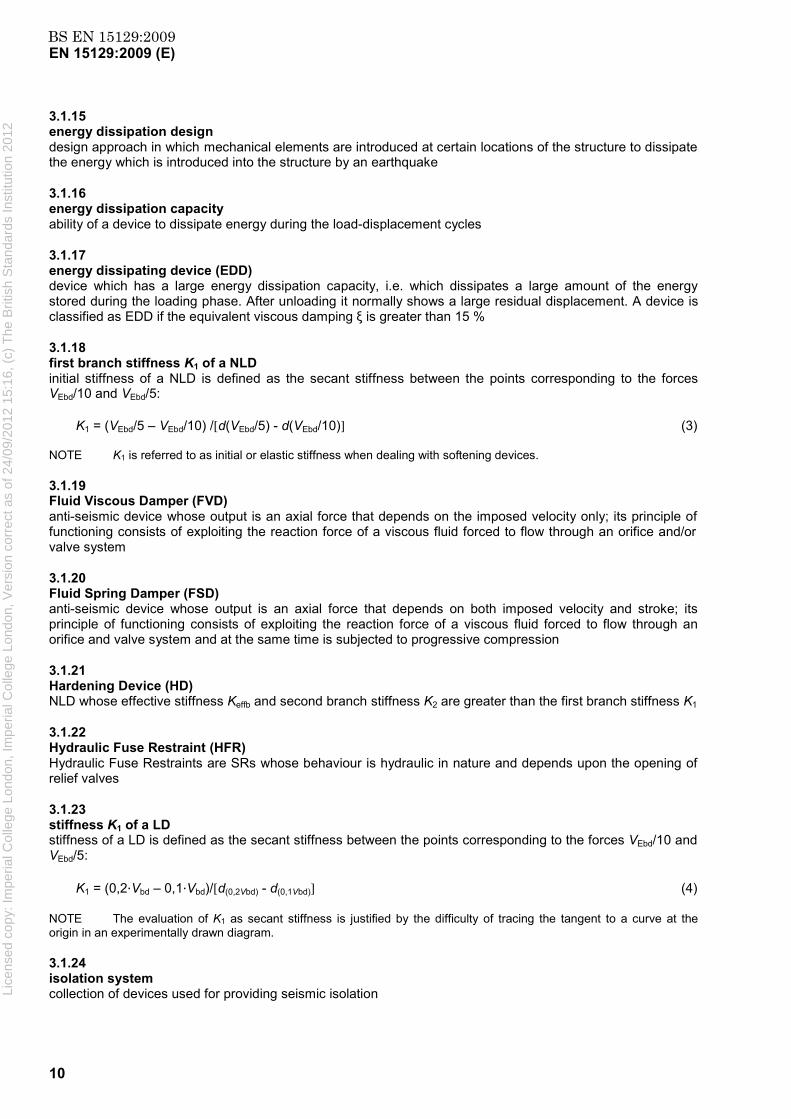
3 Terms, definitions, symbols and abbreviations
3.1 Terms and definitions
For the purposes of this document, the following terms and definitions apply.
NOTE In this European Standard, compressive forces, stresses and strains are positive.
3.1.1 activation velocity velocity at which a Shock Transmission Unit (STU) reacts with its design force
3.1.2 axial force NEd acting on a device under the design seismic action maximum value during the action is denoted NEd,max and the minimum value NEd,min. The minimum value acting on a device may be tensile
3.1.3 core element component of a Linear Device (LD) or of a Non Linear Device (NLD) on which the mechanism characterising the device’s behaviour is based
NOTE Core elements of a LD or of a NLD are the device’s components that provide it with the flexibility and, eventually, with the energy dissipation and/or re-centring capacity or any other mechanical characteristic compatible with the requirements of a LD or of a NLD. Examples of core elements are steel plates or bars, shape memory alloy wires or bars, rubber elements.
3.1.4 design displacement dbd (of a device) total displacement (due to both translation and rotation about the vertical axis of the isolation system) that a device will undergo when the structural system is subjected to the design seismic action alone according to EN 1998-1
3.1.5 design displacement of an isolation system in a principal direction dcd horizontal displacement at the effective stiffness centre, occurring under the design seismic action alone
3.1.6 (maximum ) displacement of a device in a principal direction dEd for an anti-seismic device in a bridge dEd equals dmax, the maximum total horizontal displacement at the location of the device including all actions effects and the application of the reliability factor to dbd, according to EN 1998-2:2005, 7.6.2 (2)P
For devices in other structures dEd equals γx dbd , the design displacement increased by the reliability factor.
3.1.7 design force Vbd (of a device) force (or moment) corresponding to dbd
Lice
nsed
cop
y: Im
peria
l Col
lege
Lon
don,
Impe
rial C
olle
ge L
ondo
n, V
ersi
on c
orre
ct a
s of
24/
09/2
012
15:1
6, (
c) T
he B
ritis
h S
tand
ards
Inst
itutio
n 20
12

BS EN 15129:2009EN 15129:2009 (E)
9
3.1.8 devices elements which contribute to modify the seismic response of a structure by isolating it, by dissipating energy or by creating permanent or temporary restraints via rigid connections. The devices considered are described in the various clauses of this European Standard
3.1.9 ductility demand (of a device) displacement ductility demand referred to the theoretical bilinear cycle, and is evaluated as dbd/d1 (see 3.1.4 and 3.1.44)
NOTE The ductility demand is a useful parameter to evaluate the plastic demand of an EDD based on material hysteresis (see 3.1.17).
3.1.10 effective damping (of a device) ξeffb value of the effective viscous damping, corresponding to the energy dissipated by the device during cyclic response at the total design displacement:
ξeffb = W(dbd) /(2π VEbd dbd) (1)
where
W(dbd) = energy actually dissipated by a device during the 3rd load cycle, with maximum displacement equal to dbd.
NOTE ξeffb is introduced for a simple characterisation of the behaviour of any device. It cannot be used in the analytical calculations of the response of the structural system, unless they can be carried out by linear analysis and all the devices have the same damping and stiffness in the given direction. Where different devices are used, reference is made to the overall effective damping of the isolation system.
3.1.11 effective period Teff in the case of seismic isolation, is the period of a single degree of freedom system moving in the direction considered, having the mass of the superstructure and the stiffness equal to the effective stiffness of the isolation system
3.1.12 effective stiffness of a device in a principal direction Keffb ratio between the value of the total horizontal force transferred through the device and the component of the total design displacement in the same direction, divided by the absolute value of the total design displacement (secant stiffness)
Keffb = VEbd /dbd (2)
NOTE Keffb is introduced for a simple characterisation of the behaviour of a device. It cannot be used in the analytical calculations of the response of the structural system, unless they can be carried out by linear analysis and all the devices have the same damping and stiffness in the given direction. Where different devices are used, reference is made to the overall effective stiffness of the isolation system.
3.1.13 effective stiffness of an isolation system in a principal direction Keff sum of the effective stiffness of the devices located at the isolation interface
3.1.14 effective stiffness centre stiffness centre of an isolation system, accounting for the effective stiffness of the devices
Lice
nsed
cop
y: Im
peria
l Col
lege
Lon
don,
Impe
rial C
olle
ge L
ondo
n, V
ersi
on c
orre
ct a
s of
24/
09/2
012
15:1
6, (
c) T
he B
ritis
h S
tand
ards
Inst
itutio
n 20
12
BS EN 15129:2009EN 15129:2009 (E)
10
3.1.15 energy dissipation design design approach in which mechanical elements are introduced at certain locations of the structure to dissipate the energy which is introduced into the structure by an earthquake
3.1.16 energy dissipation capacity ability of a device to dissipate energy during the load-displacement cycles
3.1.17 energy dissipating device (EDD) device which has a large energy dissipation capacity, i.e. which dissipates a large amount of the energy stored during the loading phase. After unloading it normally shows a large residual displacement. A device is classified as EDD if the equivalent viscous damping ξ is greater than 15 %
3.1.18 first branch stiffness K1 of a NLD initial stiffness of a NLD is defined as the secant stiffness between the points corresponding to the forces VEbd/10 and VEbd/5:
K1 = (VEbd/5 – VEbd/10) /[d(VEbd/5) - d(VEbd/10)] (3)
NOTE K1 is referred to as initial or elastic stiffness when dealing with softening devices.
3.1.19 Fluid Viscous Damper (FVD) anti-seismic device whose output is an axial force that depends on the imposed velocity only; its principle of functioning consists of exploiting the reaction force of a viscous fluid forced to flow through an orifice and/or valve system
3.1.20 Fluid Spring Damper (FSD) anti-seismic device whose output is an axial force that depends on both imposed velocity and stroke; its principle of functioning consists of exploiting the reaction force of a viscous fluid forced to flow through an orifice and valve system and at the same time is subjected to progressive compression
3.1.21 Hardening Device (HD) NLD whose effective stiffness Keffb and second branch stiffness K2 are greater than the first branch stiffness K1
3.1.22 Hydraulic Fuse Restraint (HFR) Hydraulic Fuse Restraints are SRs whose behaviour is hydraulic in nature and depends upon the opening of relief valves
3.1.23 stiffness K1 of a LD stiffness of a LD is defined as the secant stiffness between the points corresponding to the forces VEbd/10 and VEbd/5:
K1 = (0,2 Vbd – 0,1 Vbd)/[d(0,2Vbd) - d(0,1Vbd)] (4)
NOTE The evaluation of K1 as secant stiffness is justified by the difficulty of tracing the tangent to a curve at the origin in an experimentally drawn diagram.
3.1.24 isolation system collection of devices used for providing seismic isolation Li
cens
ed c
opy:
Impe
rial C
olle
ge L
ondo
n, Im
peria
l Col
lege
Lon
don,
Ver
sion
cor
rect
as
of 2
4/09
/201
2 15
:16,
(c)
The
Brit
ish
Sta
ndar
ds In
stitu
tion
2012

BS EN 15129:2009EN 15129:2009 (E)
11
3.1.25 isolation interface in the case of seismic isolation, the surface which separates the substructure and the superstructure and where the isolation system is located
3.1.26 isolator device possessing the characteristics needed for seismic isolation, namely, ability to support gravity load of superstructure, and ability to accommodate lateral displacements. Isolators may also provide energy dissipation, and contribute to the isolation system’s recentring capability
NOTE In EN 1998-2, isolator may also designate the devices belonging to an isolation system, whether they support gravity loads or not.
3.1.27 linear device (LD) anti-seismic device which is characterised by a linear or almost linear load-displacement relationship up to the displacement dbd, with a stable behaviour under a large number of cycles and substantial independence from velocity. After unloading, it does not show a residual displacement. Even when some energy dissipation occurs in the device, residual displacements shall be negligible, and in any case less than 2 % of the maximum displacement
NOTE For visco-elastic devices, residual displacements can be partially or totally recovered after some hours. In this case, the final residual displacement should be referred to.
3.1.28 Mechanical Fuse Restraint (MFR) SR whose behaviour is determined by the break-away of sacrificial components
3.1.29 Non Linear Device (NLD) anti-seismic device which is characterised by a non linear load-displacement relationship, with a stable behaviour under the required number of cycles and substantial independence from velocity. A device is classified as non linear if either ξeffb is greater than 15 % or the ratio | Keffb -K1|/K1 is greater than 20 %, where ξeffb and Keffb are evaluated at the 3rd cycle with maximum displacement equal to dbd
3.1.30 Non linear Elastic Devices (NLED) NLD which normally dissipates a negligible amount of the energy stored during the loading phase. The static residual displacement after unloading shall be negligible. A device is classified as NLED if ξeffb is less than 15 % while the ratio | Keffb -K1|/K1 is greater than 20 %
Figure 1 — Initial and effective stiffness of a linear device
Lice
nsed
cop
y: Im
peria
l Col
lege
Lon
don,
Impe
rial C
olle
ge L
ondo
n, V
ersi
on c
orre
ct a
s of
24/
09/2
012
15:1
6, (
c) T
he B
ritis
h S
tand
ards
Inst
itutio
n 20
12
BS EN 15129:2009EN 15129:2009 (E)
12
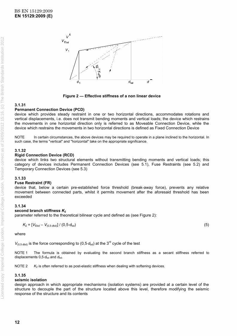
Figure 2 — Effective stiffness of a non linear device
3.1.31 Permanent Connection Device (PCD) device which provides steady restraint in one or two horizontal directions, accommodates rotations and vertical displacements, i.e. does not transmit bending moments and vertical loads; the device which restrains the movements in one horizontal direction only is referred to as Moveable Connection Device, while the device which restrains the movements in two horizontal directions is defined as Fixed Connection Device
NOTE In certain circumstances, the above devices may be required to operate in a plane inclined to the horizontal. In such case, the terms "vertical" and "horizontal" take on the appropriate significance.
3.1.32 Rigid Connection Device (RCD) device which links two structural elements without transmitting bending moments and vertical loads; this category of devices includes Permanent Connection Devices (see 5.1), Fuse Restraints (see 5.2) and Temporary Connection Devices (see 5.3)
3.1.33 Fuse Restraint (FR) device that, below a certain pre-established force threshold (break-away force), prevents any relative movement between connected parts, whilst it permits movement after the aforesaid threshold has been exceeded
3.1.34 second branch stiffness K2 parameter referred to the theoretical bilinear cycle and defined as (see Figure 2):
K2 = [VEbd – V(0,5 dbd)] / (0,5 dbd) (5)
where
V(0,5 dbd) is the force corresponding to (0,5 dbd) at the 3rd cycle of the test
NOTE 1 The formula is obtained by evaluating the second branch stiffness as a secant stiffness referred to displacements 0,5 dbd and dbd.
NOTE 2 K2 is often referred to as post-elastic stiffness when dealing with softening devices.
3.1.35 seismic isolation design approach in which appropriate mechanisms (isolation systems) are provided at a certain level of the structure to decouple the part of the structure located above this level, therefore modifying the seismic response of the structure and its contents
Lice
nsed
cop
y: Im
peria
l Col
lege
Lon
don,
Impe
rial C
olle
ge L
ondo
n, V
ersi
on c
orre
ct a
s of
24/
09/2
012
15:1
6, (
c) T
he B
ritis
h S
tand
ards
Inst
itutio
n 20
12

BS EN 15129:2009EN 15129:2009 (E)
13
3.1.36 service life of a device period over which a device is expected to perform within its specified parameters. The value is taken as that given in Technical Specifications of the Project, based on declarations made by manufacturers
NOTE Additional information concerning the service life is given in informative Annex B.
3.1.37 Shock-Transmission Unit (STU) device whose output is an axial force that depends on the imposed velocity; its principle of functioning consists of exploiting the reaction force of a viscous fluid forced to flow through an orifice in order to provide a very stiff dynamic connection whilst for low velocity applied loads the reaction is negligible
3.1.38 Softening Device (SD) NLD whose secant stiffness Keffb and second branch stiffness K2 are smaller than the first branch stiffness K1
3.1.39 Statically Re-centring Device (StRD) Energy Dissipating Device whose force-displacement cyclic curve at the 3rd cycle passes through or very near the origin of the axes, at a distance not greater than 0,1 dbd
3.1.40 substructure in the case of seismic isolation, the part of the structure which is located under the isolation interface and is anchored to the foundations
3.1.41 superstructure in the case of seismic isolation, the part of the structure which is isolated and is located above the isolation interface
3.1.42 Supplemental Re-centring Device (SRCD) device whose force-displacement cyclic curve at the 3rd cycle passes through or very near the origin of the axes and, for small displacement at unloading (0,1 dbd), provides a force which is at least 0,1 VEbd
NOTE The supplemental force > 0,1 VEbd is meant to counteract the effect of parasitic non-conservative forces (e.g. friction in other devices, yielding in structural elements, etc.) or other energy dissipating non re-centring devices, in order to provide the entire structural system with an overall Re-centring capability. The supplemental force is calibrated according to the re-centring requirements of the structural system.
3.1.43 Temporary Connecting Device (TCD) anti-seismic device whose output is a force that depends on the imposed velocity; its principle of functioning consists of a system providing for the required reaction force when dynamically activated whilst for slow applied movements it does provide a minor reaction
3.1.44 theoretical bilinear cycle of a NLD it is conventionally defined to identify the main mechanical characteristics of a non linear device through the first and second branch stiffness values and by the following parameters:
d1 = abscissa of the intersection point of the straight line starting at the origin with stiffness K1 and the straight line passing through (dbd, VEbd) with stiffness K2 in the experimental 3rd load cycle of a quasi static test;
V1 = ordinate of the intersection point of the straight line starting at the origin with stiffness K1 and the straight line passing through (dbd, VEbd) with stiffness K2 in the experimental 3rd load cycle of a quasi static test; Li
cens
ed c
opy:
Impe
rial C
olle
ge L
ondo
n, Im
peria
l Col
lege
Lon
don,
Ver
sion
cor
rect
as
of 2
4/09
/201
2 15
:16,
(c)
The
Brit
ish
Sta
ndar
ds In
stitu
tion
2012

BS EN 15129:2009EN 15129:2009 (E)
14
VEbd = force corresponding to dbd, obtained at the 3rd load cycle during a quasi static test.
3.2 Symbols
NOTE The list below covers most of the symbols. Others are defined at their first occurrence in the text.
3.2.1 Latin upper case letters
A Area m2
F Load, force acting on a device MN
G Shear modulus MPa
M Moment, bending moment MN⋅m
N Axial force MN
V Shear force MN
R Resistance MPa
S Acting force, acting moment, shape factor MN, MN⋅m
T Temperature, total thickness °C, mm
E Modulus, energy GPa, MJ
K Stiffness of a device MN/m
3.2.2 Latin lower case letters
a Acceleration, length ms-2, m
b Length m
d Displacement (translation or rotation) of a device m
f Strength, frequency MPa, Hz
t Thickness of a layer, tolerance, time mm, s
x, y Horizontal co-ordinates
z Vertical co-ordinates
3.2.3 Greek letters
α Coefficient of thermal expansion, angle of rotation /°C, rad
γ Partial factor, over-strength factor, reliability factor
ξ Equivalent viscous damping factor
ε Strain
µ Coefficient of friction
3.2.4 Subscripts
a actual
b bearing or device
c compression
cr critical
d design
e elastomer
Lice
nsed
cop
y: Im
peria
l Col
lege
Lon
don,
Impe
rial C
olle
ge L
ondo
n, V
ersi
on c
orre
ct a
s of
24/
09/2
012
15:1
6, (
c) T
he B
ritis
h S
tand
ards
Inst
itutio
n 20
12

BS EN 15129:2009EN 15129:2009 (E)
15
eff effective, equivalent value at design displacement
el elastic
h horizontal
i i-th cycle, i-th element (generic)
in initial
k characteristic
max maximum
min minimum
res residual
s steel
sc secant
u ultimate
v vertical, velocity
x horizontal co-ordinate, increased reliability
y horizontal co-ordinate
z vertical co-ordinate
E related to seismic situation
I importance
L lower limit of service range
M material
R resistance value
S acting value
U upper limit of service range
1 conventional elastic limit, first branch in the theoretical bilinear cycle of a NLD
2 design displacement and force, second branch in the theoretical bilinear cycle of a NLD
3 3rd cycle
φ related to bending
3.3 Abbreviations
DP Design properties
DRD Dynamically Re-centring Device
DSC Differential Scanning Calorimeter
EDD Energy Dissipating Device
FPC Factory Production Control
FR Fuse Restraint
FSD Fluid Spring Damper Lice
nsed
cop
y: Im
peria
l Col
lege
Lon
don,
Impe
rial C
olle
ge L
ondo
n, V
ersi
on c
orre
ct a
s of
24/
09/2
012
15:1
6, (
c) T
he B
ritis
h S
tand
ards
Inst
itutio
n 20
12

BS EN 15129:2009EN 15129:2009 (E)
16
FVD Fluid Viscous Damper
HD Hardening Device
HDRB High Damping Rubber Bearing
HFR Hydraulic Fuse Restraint
LBDP Lower Bound Design Properties
LD Linear Device
LDRB Low Damping Rubber Bearing
LRB Lead Rubber Bearing
MFR Mechanic Fuse Restraint
NDP Nationally Determined Parameters
NLD Non Linear Device
NLED Non Linear Elastic Device
NRD Non Re-centring Device
PCD Permanent Connection Device
PPRB Polymer plug rubber bearing
RCD Re-Centring Device
SD Softening Device
SLS Serviceability Limit State
SMA Shape Memory Alloys
SR Sacrificial (Fuse) Restraint
SRCD Supplement Re-Centring Device
StRD Statically Re-centring Device
STU Shock-Transmission Unit
TCD Temporary Connecting Device
UBDP Upper Bound Design Properties
ULS Ultimate Limit State
3.4 List of devices
Symbols representing the most common types of devices are given in Table 1. Lice
nsed
cop
y: Im
peria
l Col
lege
Lon
don,
Impe
rial C
olle
ge L
ondo
n, V
ersi
on c
orre
ct a
s of
24/
09/2
012
15:1
6, (
c) T
he B
ritis
h S
tand
ards
Inst
itutio
n 20
12
BS EN 15129:2009EN 15129:2009 (E)
17
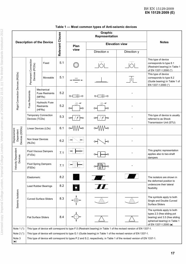
Table 1 — Most common types of Anti-seismic devices
Description of the Device
Rel
evan
t Cla
use Graphic
Representation
Notes Plan view
Elevation view
Direction x Direction y
Rig
id C
onne
ctio
n D
evic
es (R
GD
s)
Per
man
ent C
onne
ctio
n D
evic
es (P
CD
s) Fixed 5.1
This type of device corresponds to type 8.1 (Restraint bearing) in Table 1 of EN 1337-1:2000 (*)
Moveable 5.1
This type of device corresponds to type 8.2 (Guide bearing) in Table 1 of EN 1337-1:2000 (°)
Fuse
Res
train
ts Mechanical
Fuse Restraints (MFRs)
5.2
-
Hydraulic Fuse Restraints (HFRs)
5.2
-
Temporary Connection Devices (TCDs)
5.3
- This type of device is usually referred to as Shock Transmission Unit (STU)
Dis
plac
emen
t D
epen
dent
D
evic
es (D
DD
s)
Linear Devices (LDs) 6.1 -
Non linear Devices (NLDs)
6.2 -
Vel
ocity
Dep
ende
nt
Dev
ices
Fluid Viscous Dampers (FVDs)
7.1
- This graphic representation applies also to two-shaft dampers
Fluid Spring Dampers (FSDs)
7.1 -
Sei
smic
Isol
ator
s
Elastomeric 8.2 The isolators are shown in
the deformed position to underscore their lateral flexibility
Lead Rubber Bearings 8.2
Curved Surface Sliders 8.3
The symbols apply to both Single and Double Curved Surface Sliders
Flat Surface Sliders 8.4
The symbols apply to both types 2.3 (free sliding pot bearing) and 3.5 (free sliding spherical bearing) in Table 1 of EN 1337-1:2000 (■)
Note 1 (*): This type of device will correspond to type F.0 (Restraint bearing) in Table 1 of the revised version of EN 1337-1.
Note 2 (°): This type of device will correspond to type G.1 (Guide bearing) in Table 1 of the revised version of EN 1337-1.
Note 3 (■):
This type of device will correspond to types P.2 and S.2, respectively, in Table 1 of the revised version of EN 1337-1.
Lice
nsed
cop
y: Im
peria
l Col
lege
Lon
don,
Impe
rial C
olle
ge L
ondo
n, V
ersi
on c
orre
ct a
s of
24/
09/2
012
15:1
6, (
c) T
he B
ritis
h S
tand
ards
Inst
itutio
n 20
12

BS EN 15129:2009EN 15129:2009 (E)
18
4 General design rules
NOTE 1 Additional information concerning the general design rules is given in Annex B.
NOTE 2 The seismic analysis and design of the isolating system of an entire structure is ruled by EN 1998-1, with specific requirements for buildings in EN 1998-1 and EN 1998-2 for bridges. In the seismic analysis of the isolating system of an entire structure, design action effects on individual components, including anti-seismic devices are assessed on the basis of the design seismic action deduced from the structural seismic analysis.
4.1 Performance requirements and compliance criteria
4.1.1 Fundamental requirements
The anti-seismic devices and their connections to the structure shall be designed and constructed in such a way that the following requirements are met, each with an adequate degree of reliability:
a) No failure requirement
The anti-seismic devices and their connections to the structure shall be designed and constructed to withstand the seismic action effects defined by EN 1998-1 for buildings or by EN 1998-2 for bridges without local or global failure, thus retaining a residual mechanical resistance, including when applicable a residual load bearing capacity, after the seismic event.
NOTE 1 The non failure requirement concerns the structure as a whole and, when appropriate, the device and its connection to the structure. It does not concern Fuse Restraints. The device is expected to sustain damage in this event which may necessitate repair or replacement.
b) Damage limitation requirement
The anti-seismic devices and their connections to the structure shall be designed and constructed to withstand a seismic action having a larger probability of occurrence than the design seismic action, without the occurrence of damage and the associated limitations of use, the costs of which would be disproportionately high in comparison with the costs of the structure itself. The seismic action to be considered for the damage limitation requirement is defined in 2.1 (1) P of EN 1998-1:2004.
NOTE 2 The device is expected to sustain no or very minor damage in this event which does not necessitate replacement.
Non-seismic design situations not covered by this European Standard shall also be considered according to relevant European Standards.
NOTE 3 This implies in particular the compliance with Eurocodes.
4.1.2 Increased reliability of structural system
According to EN 1998-1:2004, subclause 10.3 (2) P, in the case of isolation systems, increased reliability shall be required for the isolation devices and their connections to the structure.
NOTE 1 In EN 1998-1, this is implemented by applying a magnification factor γx on seismic displacements of each unit. In EN 1998-2, this magnification factor is called γIS. Recommended minimum values of γx or γIS for isolators are given in EN 1998-1 and EN 1998-2 respectively. Mandatory values may be given in the corresponding National Annexes.
For devices not used in an isolation system, depending on the role they play in the stability of the construction after the earthquake, a reliability factor γx equal or greater than 1 shall be applied to the seismic action effects on the devices and their connections to the structure.
Lice
nsed
cop
y: Im
peria
l Col
lege
Lon
don,
Impe
rial C
olle
ge L
ondo
n, V
ersi
on c
orre
ct a
s of
24/
09/2
012
15:1
6, (
c) T
he B
ritis
h S
tand
ards
Inst
itutio
n 20
12

BS EN 15129:2009EN 15129:2009 (E)
19
NOTE 2 Recommended minimum values of γx for devices other than isolators are given in the relevant clauses of this European Standard. The values should be covered by structural Eurocodes at a later stage.
NOTE 3 Higher values of γx may be defined by National Authorities or by the owner in the case of a critical structure.
4.1.3 Functional requirements
Devices and their connections to the structure shall be designed and constructed in such a way as to function according to the design requirements and tolerances throughout their projected service life, given the mechanical, physical, chemical, biological and environmental conditions expected.
Devices and their connections to the structure shall be designed, constructed and installed in such a way that their routine inspection and replacement are possible during the service life of the construction.
NOTE For the enforcement of this requirement, it is necessary that the design of the structure takes account of accessibility for both equipment and personnel.
4.1.4 Structural and mechanical requirements
Devices and their connections to the structure shall be designed and constructed in such a way that their performance characteristics conform to the design requirements, as given below:
a) Requirements at the ULS
NOTE 1 The verification of the devices at the Ultimate Limit State (ULS) is associated with the design seismic situation, with due consideration of the reliability of the structural system.
The devices and their connections to the structure shall be verified, with an adequate degree of reliability, to have an appropriate strength and ductility to withstand actions effects in the seismic design situation, taking into account the reliability factor γx of the structural system, as defined in 4.1.2, and second order effects.
At the ULS, the devices and their connections to the structure can suffer damage, but shall not reach failure except in the case of fuse restraints, for which requirements given in 5.2 apply.
Replacement of the devices after any damage suffered shall be possible without resorting to major intervention. Where applicable, they shall retain a residual capacity at least equal to the permanent actions to which they are directly subjected or to such combinations of actions corresponding to design situations (including eventually a seismic situation) that may occur after the earthquake, as defined by the structural design.
b) Requirements at the SLS
NOTE 2 The verification of the devices at the Serviceability Limit State (SLS) is associated with the damage limitation requirement and the corresponding seismic action, as defined in 4.1.1.
At the SLS, the devices and their connections to the structure shall remain in a serviceable state, at least as far as their performance under further seismic loads is concerned, and undergo only very minor or superficial damage which should not induce interruption of use, nor require immediate repair.
4.1.5 Compliance criteria
Performance requirements concerning the devices and their connections to the structure shall be satisfied by complying with the procedures set forth in the corresponding clauses of this European Standard, according to the type of devices used.
NOTE The verification of compliance criteria may be obtained by appropriate modelling or testing according to the corresponding clauses of this European Standard. Li
cens
ed c
opy:
Impe
rial C
olle
ge L
ondo
n, Im
peria
l Col
lege
Lon
don,
Ver
sion
cor
rect
as
of 2
4/09
/201
2 15
:16,
(c)
The
Brit
ish
Sta
ndar
ds In
stitu
tion
2012

BS EN 15129:2009EN 15129:2009 (E)
20
4.2 Action effects on devices
4.2.1 Seismic design situations and seismic combinations of actions
The seismic design situations defined in 4.1.1 shall be associated with the seismic combinations of actions defined in 6.4.3.4 of EN 1990:2002.
4.2.2 Effects of actions
Combinations of the effects of the components of the seismic action on the devices shall be as defined in the corresponding parts of EN 1998.
4.3 Conceptual design of the devices
4.3.1 Reliability of the devices’ behaviour
NOTE 1 An adequate reliability in the behaviour of the devices and their connections to the structure over their service life, as required in 4.1.2, is necessary in order to reduce the uncertainties inherent in seismic design.
Device components shall comply with the relevant European Standards.
NOTE 2 In the cases where European Standards do not exist, national standards may apply.
Choice of the material and construction techniques of the device and its connections to the structure shall be consistent with the design requirements determined for the structure.
A good reproducibility of the mechanical behaviour of the device and of its components shall be obtained, as defined in the relevant clauses of this European Standard.
The description of the mechanical behaviour of the device and its connections to the structure shall be based on adequate modelling and tests, as required in 4.6 and Clause 10.
The relevant mechanical and physical properties of the device and its connections to the structure or their components shall be assessed by tests through appropriate procedures, as required in 4.6 and Clause 10 and in the corresponding clauses of this European Standard.
NOTE 3 Beyond the design seismic action, including reliability factors, there should be no immediate risk of catastrophic failure of the device.
4.3.2 Capacity design
An over-strength factor γRd equal to 1,1 shall be applied to the actions transmitted by the device to the connections.
NOTE The actions transmitted by the device to the connections are based on the UBDP (see 4.4.2).
4.3.3 Maintenance
All devices and their connections to the structure shall be accessible for inspection and maintenance.
NOTE This is under the responsibility of the designer of the structure. See 10.5.1 of EN 1998-1:2004, and 7.7.3 of EN 1998-2:2005.
A periodic inspection and maintenance programme for the devices and their connections shall be elaborated during the project implementation.
Lice
nsed
cop
y: Im
peria
l Col
lege
Lon
don,
Impe
rial C
olle
ge L
ondo
n, V
ersi
on c
orre
ct a
s of
24/
09/2
012
15:1
6, (
c) T
he B
ritis
h S
tand
ards
Inst
itutio
n 20
12

BS EN 15129:2009EN 15129:2009 (E)
21
4.3.4 Modification and replacement of devices
Modification of devices and associated components shall conform to the relevant clauses of this European Standard. Otherwise, such modification shall not be permitted.
Devices used for replacement shall comply with this European Standard and with additional requirements originally defined by the owner, unless otherwise requested by the owner at the time of the replacement.
Inspection and maintenance procedures defined in 4.3.3 shall be updated as necessary.
4.3.5 Device documentation
The documentation shall indicate the type of the device, its performance and the range of temperature and other environmental conditions specified for the project under consideration.
The documentation shall indicate details, sizes and tolerances related to installation of the devices and their connections to the structure, and shall refer to this European Standard.
The documentation shall include design checks and results of the relevant type tests and factory production control tests of the devices used in the project.
The documentation shall indicate aspects of particular importance for the installation of the devices at their location in the structure.
The documentation shall contain a detailed description of inspection and maintenance procedures as required in 4.3.3 or in the corresponding clauses of this European Standard.
The documentation shall contain the description of replacement procedures for the device.
NOTE It is under the responsibility of the designer of the structure to decide which documents are provided by himself or requested from the manufacturer.
4.4 General properties
4.4.1 Material properties
Materials used in the design and construction of the devices and their connections to the structure shall conform to existing European Standards where appropriate.
NOTE 1 In the cases where European Standards do not exist, national standards or other specifications may apply.
Material properties shall be appropriately assessed so as to represent their behaviour adequately under the conditions of strain and strain rate which can be attained during the design seismic situation.
Material properties shall take into account the environmental (physical, biological, chemical and nuclear) conditions with which devices can be faced over their service life. In particular, the effects of temperature variation shall be properly taken into account.
Material properties shall take into account the ageing phenomena that can occur during the service life of the device.
Material properties shall be represented by representative values.
NOTE 2 Representative values are defined in EN 1990.
4.4.2 Device properties to be used in the analysis
Device properties shall take into account the loading history and the accumulated strain cycles.
Lice
nsed
cop
y: Im
peria
l Col
lege
Lon
don,
Impe
rial C
olle
ge L
ondo
n, V
ersi
on c
orre
ct a
s of
24/
09/2
012
15:1
6, (
c) T
he B
ritis
h S
tand
ards
Inst
itutio
n 20
12

BS EN 15129:2009EN 15129:2009 (E)
22
Device properties shall be appropriately assessed so as to represent their behaviour adequately under the conditions of deformation and deformation rate which can be attained during the design seismic situation.
Device properties shall take into account the environmental (physical, biological, chemical and nuclear) conditions with which devices can be faced over their service life. In particular, the effects of temperature variation shall be properly taken into account.
Device properties shall take into account the ageing phenomena that can occur during the service life of the device.
Design (mean) properties (DP) shall be derived from the type tests.
Two sets of design properties of the system of devices shall be properly established:
Upper bound design properties (UBDP);
Lower bound design properties (LBDP).
The overall variations of device properties shall lie between the Lower Bound and the Upper Bound. The lower bound shall correspond to the minimum representative value in the conditions where lower values of properties are obtained. The upper bound shall correspond to the maximum representative value in the conditions where upper values of properties are obtained. Both bounds shall be obtained by considering the quasi permanent values of the variable actions, as defined in the seismic combinations of actions, according to EN 1990, except for temperature for which the frequent value shall be taken into account.
LBDP and UBDP of a given property are representative values obtained from testing procedures defined in the corresponding clauses of this European standard.
The ratio between upper bound and lower bound representative value of any performance related device properties shall not exceed the limits defined in the relevant clauses.
The lower and upper bound representative values shall be determined from the type tests and the following variations:
FPC test tolerance ± 20 % (unless a lower variability has been agreed for the acceptance tests);
temperature varying between TU and TL (being the upper and lower values of the temperature considered in the design seismic situations as in EN 1990, with due regard to quasi-permanent values of the temperature);
ageing consistent with the service life considered.
Combination factors of actions shall be those considered in the seismic combinations of actions.
NOTE 1 Specific phenomena, such as low temperature crystallisation, can be relevant. They are dealt with in the corresponding clauses.
NOTE 2 According to EN 1998-1:2004, 10.8 (1)P and EN 1998-2:2005, 7.5.2.4 (3)P and (4)P, the structural analysis takes into account the extreme situations resulting from the consideration of all upper bound design properties (UBDP) and lower bound design properties (LBDP).
NOTE 3 Values of TU and TL are determined according to EN 1991-1-5.
4.4.3 Re-centring capability
In the case of an equivalent linear analysis, to ensure adequate re-centring capability of a seismically isolated structure, it shall be verified that, for a deformation from 0 to dEd : Li
cens
ed c
opy:
Impe
rial C
olle
ge L
ondo
n, Im
peria
l Col
lege
Lon
don,
Ver
sion
cor
rect
as
of 2
4/09
/201
2 15
:16,
(c)
The
Brit
ish
Sta
ndar
ds In
stitu
tion
2012
BS EN 15129:2009EN 15129:2009 (E)
23
Es ≥ 0,25 Eh (6)
where
Es is the reversibly stored energy (elastic strain energy and potential energy) of the isolation system, including those elements of the structure influencing its response;
Eh is the energy dissipated by the isolation devices.
In the cases where a time history analysis is performed, the most unfavourable value of the considered effect shall be retained from each time history. Then the design value of the action effect shall be deduced from the results obtained from the different time history analyses, according to EN 1998-1:2004, 4.3.3.4.3.
NOTE According to EN 1998-1, this rule also applies to the design of the structure.
4.5 Constitutive laws
Appropriate constitutive laws of the devices shall be established by tests as required in 4.6 and Clause 10 or in the relevant clauses of this European Standard, so that the behaviour of the structure in the seismic situation may be properly predicted.
NOTE 1 The structural analysis is based on these appropriate constitutive laws. For this structural analysis, the rules given in the corresponding parts of EN 1998 apply.
The behaviour of the devices shall be appropriately modelled to account for non linear effects as well as any other effects, for instance, those due to velocity dependence or restraints.
NOTE 2 For the devices considered, some guidance on modelling constitutive laws is given in the corresponding clauses of this European Standard.
4.6 Validation of anti-seismic devices
Any type of device shall be subjected to a technical validation procedure, which shall include elements proving that the device conforms to its functional requirements. It shall prove that the device will remain operational within its domain of use, including the seismic situation, over its service life. It shall include at least the following:
a description of the ranges of parameters relevant for the type of device under consideration covered by the validation procedure;
a method to estimate the expected service life;
proof of the device’s ability to function in a reliable and stable way during its service life;
values of the mechanical properties of the device, as defined in 4.4;
range of acceptable environmental conditions;
description of the behaviour beyond design seismic action to determine the γm values;
description of suitable constitutive laws for analysis;
a constitutive model describing the behaviour of the device under different conditions of use, including all combinations of actions as defined in EN 1990, representative of the physical phenomena which are expected during the lifetime, notably during the seismic movement;
NOTE The influence of the interaction with adjacent structural elements should be taken into account.
Lice
nsed
cop
y: Im
peria
l Col
lege
Lon
don,
Impe
rial C
olle
ge L
ondo
n, V
ersi
on c
orre
ct a
s of
24/
09/2
012
15:1
6, (
c) T
he B
ritis
h S
tand
ards
Inst
itutio
n 20
12

BS EN 15129:2009EN 15129:2009 (E)
24
type tests, as required in Clause 10, covering the anticipated ranges of use of the relevant parameters.
A validation file, including all the elements gathered in the validation procedure, shall be presented for the device. It shall include at least a list of its properties and a description of the device, of its domain of use, of its constitutive laws, of the analytical model when included in a structural model, and of the associated detailing. It shall include all information related to geometrical, physical, biological, chemical and mechanical characteristics and tolerances.
5 Rigid connection devices
NOTE 1 Rigid Connection Devices are used to constrain movements in one or more directions. Therefore, in principle they do not possess any horizontal distortion capability. However, some deformations are unavoidable and are subjected to the requirements specified under this clause.
NOTE 2 Cable restraints are outside the scope of this European Standard.
5.1 Permanent Connection Devices
Permanent Connection Devices (PCD) shall allow vertical axial movements and rotations, i.e. shall not transmit vertical loads and bending moments.
Moveable connection devices shall restrain movements in one direction only. Fixed connection devices shall restrain movements in two directions.
PCD not modifying the natural period of the structure nor dissipating energy can consist of structural bearings governed by EN 1337 and the various elements shall be designed and manufactured in accordance with the relevant part of EN 1337.
Loads, load effects and load combinations shall be determined in accordance with the Eurocode series and shall be specified in accordance with EN 1337-1:2000, Annex B.
5.2 Fuse Restraints
5.2.1 Performance requirements
Fuse Restraints (FRs) or Sacrificial Restraints (SR), below a certain pre-established force threshold (break-away force), shall impede any relative movements between connected parts, whereas they shall freely permit the movements after the aforesaid threshold has been exceeded.
NOTE 1 FRs can be of the mechanical type (MFRs) (when transition is determined by the break-away of sacrificial restraints) or hydraulic in nature (HFRs) (when transition is governed by the opening of an overpressure valve).
NOTE 2 Fuse Restraints are typically used to control the transition between the service and seismic load condition. They connect in a rigid manner two structural components in order to avoid relative displacement for service load condition, but above a preset force threshold they disconnect the above-mentioned structural components. In this way, they are used to bypass the seismic protection system under service conditions, but leave it free to work during the design earthquake. In order not to modify the behaviour of the isolation and/or damping system, FRs are commonly characterised by a sudden transition from service to seismic load condition.
5.2.2 Material properties
5.2.2.1 General
In addition to the requirements in the following subclauses, the materials shall be selected for their compatibility with the expected temperature range of the structure.
Lice
nsed
cop
y: Im
peria
l Col
lege
Lon
don,
Impe
rial C
olle
ge L
ondo
n, V
ersi
on c
orre
ct a
s of
24/
09/2
012
15:1
6, (
c) T
he B
ritis
h S
tand
ards
Inst
itutio
n 20
12

BS EN 15129:2009EN 15129:2009 (E)
25
5.2.2.2 Materials
Fuse restraints shall be manufactured from materials in accordance with the relevant European Standards.
5.2.2.3 Structural Fasteners
Specification and certification of material shall correspond to the requirements referring to stressing and weldability.
All materials used shall comply with ISO 898.
5.2.2.4 Welding
Welding materials shall comply with EN 1090-2.
5.2.3 Design requirements
FRs shall be designed to withstand service loads with no yielding or failure.
FRs shall be designed so that the maximum design deformation is not exceeded.
NOTE FRs, according to the requirements of a particular application, may have to be designed in order to withstand fatigue loads.
FRs shall be designed to operate within the design load tolerance td.
For FRs design purposes, the operating load shall not be factored.
For the design of the MFR’s failing component (sacrificial element) and the set-up of the HFR’s overpressure valve, any over-strength factor is not applicable (unfactored load). Over-strength factors are applicable to all the other components of the FR units. Clause 4 does not apply to FRs.
After failure, FRs shall not interfere with functioning of anti-seismic devices (if any).
5.2.4 Type Testing
5.2.4.1 General
Type tests of devices shall be performed whenever new devices with an internal or external geometry, materials or kind of constraints different from those already qualified are designed.
If the raw material used for the production does not come from the same batch as used for previous devices, it shall be shown by calculation based on tests on the actual batch of material that the design load tolerance is not exceeded when the actual material batch properties are applied.
5.2.4.2 Service Load Test
The FR shall be subjected three times to a monotonically imposed load up to the maximum service load.
No yielding or failure shall occur. During the three cycles, the maximum measured deformation corresponding to the maximum service load shall be less than or equal to the design load.
5.2.4.3 Fatigue Test
Where required the fatigue test shall be performed.
The FR shall be subjected to 2 million cycles at the expected level of fatigue load.
Lice
nsed
cop
y: Im
peria
l Col
lege
Lon
don,
Impe
rial C
olle
ge L
ondo
n, V
ersi
on c
orre
ct a
s of
24/
09/2
012
15:1
6, (
c) T
he B
ritis
h S
tand
ards
Inst
itutio
n 20
12

BS EN 15129:2009EN 15129:2009 (E)
26
No yielding or failure shall occur.
In order to verify that the fatigue effect is not influencing the FR strength resistance, the test described in 5.2.4.2 and 5.2.4.4 shall be performed on two samples, one subjected to the fatigue load and one not subjected to fatigue load history.
5.2.4.4 Break-away Test
The FR shall be subjected to a monotonically imposed load up to its break-away load.
The SR shall fail within the design load tolerance td to be given by the Structural Engineer.
NOTE In the absence of different tolerance limits provided by the Structural Engineer, a typical tolerance limit of ± 15 % is recommended.
5.2.5 Factory production control tests
If the raw material used for the production does not come from the same batch as used for manufacture of the prototypes, it shall be shown by calculation that the design load tolerance is not exceeded when the actual material batch properties are applied.
5.3 Temporary (dynamic) connection devices
5.3.1 Functional requirements
Within the tolerances specified by the Structural Engineer, the Temporary Connection Devices (TCDs), commonly referred to as Shock Transmission Units (STUs), shall provide for an output force in tension and/or compression that complies with the design displacement requirements provided by the Structural Engineer when the activation velocity is exceeded.
In the presence of thermally induced or other slowly imposed movements, the TCD shall develop a reaction force less than 10 % of its design force, or a lower value as specified by the Structural Engineer.
NOTE 1 The above requirement is aimed at avoiding fatigue load transmission to the structure.
The velocity associated with thermal and/or time dependent effects may be estimated by the Structural Engineer considering the characteristics of the particular structure under design. Values of the order of 0,01 mm/s are commonly higher than most observed in practice.
NOTE 2 Slow movements induced by thermal and/or time dependent effects are characterised by velocities that are some orders of magnitude lower than those of seismic origin. Thus, the activation velocity value of a TCD is not critical and commonly set in the range from 0,5 mm/s to 5 mm/s.
The TCD’s output force shall depend on velocity only and shall not change with its stroke position and temperature.
The TCD shall be capable of operating at the seismic intensity specified by Structural Engineer without degradation of performance or reduction of service life.
The TCD’s design stroke shall take into account long-term effects, thermally induced displacements, dynamic deformation and any adjustment length required by the Structural Engineer. The stroke shall in any case be not less than ± 50 mm for bridges or ± 25 mm for buildings.
To maintain the transmitted load aligned along its major axis and avoid undesired bending effects that may be detrimental for the sealing system, the TCD shall be equipped with spherical hinges at both ends. The rotation capacity of the self-lubricating spherical hinges shall be determined by the Structural Engineer giving consideration to live load effects, earthquake movements, installation misalignments, etc. The rotation shall in any case be not less than ± 2°.
Lice
nsed
cop
y: Im
peria
l Col
lege
Lon
don,
Impe
rial C
olle
ge L
ondo
n, V
ersi
on c
orre
ct a
s of
24/
09/2
012
15:1
6, (
c) T
he B
ritis
h S
tand
ards
Inst
itutio
n 20
12

BS EN 15129:2009EN 15129:2009 (E)
27
Clevis plates or other components shall not geometrically impede the design rotation.
5.3.2 Material properties
5.3.2.1 General
The materials shall be selected for their compatibility with the expected service temperature range, taking account of both the environmental temperature and any changes produced by the functioning of the device.
5.3.2.2 Materials
Temporary Connection Devices shall be manufactured from ferrous materials in accordance with one of the following standards:
EN 10025, EN 10083, EN 10088, ISO 3755 or ISO 1083.
TCD may be made out of non ferrous materials but shall be subjected to EOTA procedure.
5.3.2.3 Active Surfaces
Active Surface of the piston rod shall be made of stainless steel or shall be nickel and/or hard chromium plated as appropriate.
The stainless steel shall be in accordance with EN 10088.
The hard chromium plating process shall comply with the requirements of EN ISO 6158.
The nickel plating process shall comply with the requirements of EN ISO 4526.
The minimum total thickness of the hard plating shall be 70 µm, unless the material substrate is made of stainless steel, in which case the minimum plating thickness may be reduced to 40 µm.
The plating shall be free from cracks and pores.
The surface of the base material shall be free from surface porosity, shrinkage cracks and inclusions.
The final surface roughness Rz in accordance with EN ISO 4287 of the plated surface shall not exceed 3µm.
NOTE Both the base material and hard plating may be polished to achieve the specified surfaced roughness.
5.3.2.4 Viscous Fluid
The viscous fluid used shall be non-toxic, non-flammable and chemically inert. If a fluid other than one that is silicone-based is used, the above-mentioned characteristics shall be demonstrated and certified by the fluid manufacturer.
Hydrocarbon-based fluids shall not be used unless otherwise specified by the Structural Engineer.
5.3.3 Design Requirements
The device shall be so designed that no yielding will result from the application of service loads and no failure will result from application of ultimate loads.
The TCD shall allow for thermal expansion and contraction of the hydraulic fluid to prevent excessive build-up of internal pressure or vacuum pressure.
Lice
nsed
cop
y: Im
peria
l Col
lege
Lon
don,
Impe
rial C
olle
ge L
ondo
n, V
ersi
on c
orre
ct a
s of
24/
09/2
012
15:1
6, (
c) T
he B
ritis
h S
tand
ards
Inst
itutio
n 20
12
BS EN 15129:2009EN 15129:2009 (E)
28
The TCD shall be designed and constructed to be maintenance free for its expected life under the anticipated service conditions.
The TCD’s components (i.e. piston rod) shall be so designed as to avoid buckling instability when loaded with the factored design load in its fully extended configuration and considering 0,10 coefficient of friction for the spherical hinges (unless experimental data are available).
The reliability factor γx for the TCD shall be 1,5, unless an overload protection system is incorporated.
Whenever a TCD is equipped with an overload system preventing an excessive pressure build-up, such system shall begin to function at a force threshold 110 % of the design force. In this case, the minimum value of the reliability factor γx for the TCD shall be 1,1 and shall be applied to the overload system force threshold.
The device shall be designed to withstand an acceleration (applied to its own mass) perpendicular to the direction of the movement equal to the maximum acceleration predicted at its location by the seismic analysis. In the absence of acceleration data, the device shall be designed to withstand a load perpendicular to the direction of the movement equal to at least twice its own weight in combination with the maximum axial load.
5.3.4 Type Testing
5.3.4.1 General
Type testing shall be performed whenever a new product differs by more than ± 20 % in terms of load capacity and has a stroke more than 20 % larger than a previously tested unit. For previous tests to be valid, conceptual design and materials shall be the same as used before.
The tests listed below need not be performed in the order they are presented, except that the seal wear test shall be carried out before the Impulsive load test and the overload capacity test. Whenever critical, the tests described below shall be repeated at the maximum and minimum expected service temperatures.
5.3.4.2 Pressure Test
Where applicable, an internal pressure shall be applied to each TCD equal to 125 % of that corresponding to the maximum TCD load. This pressure shall be maintained for 120 s.
The requirement is that no visible leakage or signs of physical deterioration or degradation in subsequent performance shall be observed.
5.3.4.3 Low velocity test
NOTE The object of the imposed low velocity test is to evaluate the TCD’s axial force resistance under simulated thermal movements.
The loading history shall be the following: One (1) fully reversed cycle of imposed axial displacement from 0 to dth, to –dth, to 0 at constant velocity v1 ≤ 0,1 mm/s.
The acceptance criterion shall be the following:
Throughout the displacement cycle the TCD shall develop a reaction force not more than 10 % of its design force, or a lower value as specified by the Structural Engineer.
Both loading history (axial displacement vs. time) and force vs. displacement loop shall be continuously recorded and plotted.
Alternatively the test shall be the following: One (1) fully reversed cycle imposing a constant force equal to 10 % of its design rated force, from 0 to at least dth (d+) and then to at least –dth (d-) and back to 0. Li
cens
ed c
opy:
Impe
rial C
olle
ge L
ondo
n, Im
peria
l Col
lege
Lon
don,
Ver
sion
cor
rect
as
of 2
4/09
/201
2 15
:16,
(c)
The
Brit
ish
Sta
ndar
ds In
stitu
tion
2012

BS EN 15129:2009EN 15129:2009 (E)
29
The acceptance criterion shall be the following:
The average recorded constant velocity (2(|d+|+|d-|)/T where T is the cycle duration) shall be higher than 0,01 mm/s.
The value of dth shall be specified by the Structural Engineer, but shall not be less than 10 mm.
Both the loading history (axial force vs. time) and the displacement vs. time shall be continuously recorded and plotted.
5.3.4.4 Seal Wear Test
NOTE The object of the test is to assure that the seal will withstand movement due to thermal effects over the assumed design life without leakage of the fluid.
The TCD shall be cyclically tested for 10 000 cycles at an amplitude equal to the expected maximum thermal displacement.
As most TCDs are characterised by a high reaction capacity even at low velocity, the main orifice system may be by-passed in order to reduce the TCD reaction and the pressure build-up so that the test can be performed in a short time. Alternatively, at the discretion of the manufacturer and whenever the TCD normal operation internal pressure is less than 2 MPa, the fluid may be removed, entirely or partially, before the test and refilled into the TCD at the end of the test.
After test, the TCD shall be tested according to 5.3.4.5 and 5.3.4.6 to verify the proper functioning of the sealing system.
5.3.4.5 Impulsive Load Test
NOTE 1 The object of this test is to verify the behaviour of an TCD in terms of displacement and activation velocity when subjected to its design load applied as an impulse.
The loading history shall be imposed in the following manner: apply the design load in less than 0,5 s, maintain it constant for 5 s, reverse it in less than 1 s, and finally maintain it for another 5 s.
NOTE 2 The time of constant load may be increased by the Structural Engineer.
The acceptance criterion shall be the following:
The displacement after the first 0,5 s shall not exceed the design value at the design force Fd, while reversing from +Fd to -Fd the total deflection shall not exceed twice the design value.
The velocity measured during the sustained load portion shall not exceed the activation velocity.
5.3.4.6 Overload Test
NOTE The object of this test is to verify the overload capacity of a TCD or the activation of the over-load relief system.
The loading history shall be imposed in the following manner: apply a load equal to 1,5 times the design load in less than 0,5 s, maintain it constant for 5 s, reverse it in less than 1 s, and finally maintain it for another 5 s.
When the device is equipped with an over-load relief system set at a force lower than 1,5 times the design load, the test may be performed to verify the relief system activation.
The acceptance criterion shall be the following:
The device shall not show any damage to the system or any leakage of fluid. Lice
nsed
cop
y: Im
peria
l Col
lege
Lon
don,
Impe
rial C
olle
ge L
ondo
n, V
ersi
on c
orre
ct a
s of
24/
09/2
012
15:1
6, (
c) T
he B
ritis
h S
tand
ards
Inst
itutio
n 20
12

BS EN 15129:2009EN 15129:2009 (E)
30
5.3.4.7 Cyclic Load Test
NOTE The object of the test is to evaluate the TCD’s behaviour when subjected to the design load applied cyclically for a time equal to the duration of the expected earthquake.
The loading history shall be imposed in the following manner: apply a number of sinusoidal force cycles of the type F(t)=F0·sin(2π⋅f0⋅t), where force F0 and frequency f0 (Hz) and the duration of the test shall be chosen by the Structural Engineer. The test duration shall be equal to that of the intense phase of the expected earthquake, but in any case shall not be less than 15 s.
The acceptance criterion shall be the following:
The TCD’s deflection at the design load shall not be greater then the design value;
The device shall not show any damage to the system or any leakage of fluid.
5.3.5 Factory Production Control Tests
For Quality Control purposes one unit per production lot shall be subjected to the following tests:
Pressure Test;
Low Velocity Test;
Impulsive Load Test.
A production lot is defined as no more than twenty (20) units having the same design details with the exception of the stroke. The production unit to be tested within the production lot shall be the one with the longest stroke.
Pressure test shall be performed on 100 % of the production units.
All the tests shall be performed at ambient temperature (23 ± 3) °C.
Table 2 summarises the required tests for Initial Type Testing and factory production control tests.
Table 2 — Tests for Initial Type Testing and factory production control tests
Pressure Test
Low Velocity Test
Seal Wear Test
Impulsive Load Test
Overload Test
Cyclic Load Test
Type Tests x * x x * x x * x
FPC Tests x * x * x * (*) Test performed always at ambient temperature
6 Displacement Dependent Devices
6.1 General
This part of this European Standard deals with the requirements for the design and manufacturing of linear and non linear anti-seismic devices which do not carry vertical loads, whose behaviour is mainly dependent on displacement rather than on velocity, for use in structures erected in seismic areas in accordance with EN 1998. Li
cens
ed c
opy:
Impe
rial C
olle
ge L
ondo
n, Im
peria
l Col
lege
Lon
don,
Ver
sion
cor
rect
as
of 2
4/09
/201
2 15
:16,
(c)
The
Brit
ish
Sta
ndar
ds In
stitu
tion
2012

BS EN 15129:2009EN 15129:2009 (E)
31
NOTE 1 Linear devices (LD) are characterised by a linear or quasi-linear behaviour and are used to change favourably the dynamic characteristics of a structural system. Non-linearity and/or energy dissipation should be compatible with the linear modelling for design analyses of the structural systems including these devices.
NOTE 2 Non Linear Devices (NLD) are characterised by a strongly non linear behaviour and are used to change favourably the dynamic characteristics of a structural system, by introducing significant non-linearity and/or energy dissipation, which should be appropriately taken into account in the non linear modelling for design analyses of the structural systems including these devices.
6.2 Performance Requirements
Displacement Dependent Devices (DDD) shall be able to sustain a displacement γx dbd, taking into account a partial factor γb on the maximum force or the displacement of the device and action effects other than seismic, which can affect the initial configuration of the device.
The force-displacement capacity of a device shall be measured up to a displacement of γb γx dbd or a load of γbγx VEbd, whichever is reached first.
Its force-displacement curve in the loading phase shall not show a decreasing trend while increasing the displacement up to γbγxdbd or the force up to γbγx VEbd.
The value of γb shall be not less than 1,1.
Whenever a DDD is used as a component of a seismic isolation system for buildings, bridges or other structures, the γb and γx values shall be adjusted in order to comply with the displacement capacity of the isolators (see Clause 8).
The behaviour of a DDD is identified by the effective stiffness Keffb and the effective damping ξeffb, as well as by the first branch stiffness K
1 and the second branch stiffness K
2 in the case of a NLD.
NOTE 1 In order to use the theoretical bilinear cycle to model a device’s behaviour in non linear simulation analyses of structural systems, the unloading branch of the theoretical cycle should approximate at best the real behaviour of the device. With this aim, the value of ξeffb of the theoretical cycle should not differ from the value of ξeffb of the 3rd cycle of a type test by more than ± 10 %.
A DDD shall comply with the requirements for non seismic conditions as defined by the Structural Engineer, according to the relevant European Standards.
A linear device shall have both the equivalent damping of the hysteretic energy dissipation ξξξξeffb,h less than 15 % and the ratio |Keffb,h- K1,h|/ K1,h less than 0,2.
NOTE 2 The hysteretic properties of a linear device, such as the equivalent damping of the hysteretic energy dissipation ξξξξeffb,h and the corresponding stiffness values Keffb,h and K1,h, can be evaluated by making cyclic tests at a very low frequency such as f < 0,001 Hz.
The experimental values of the behavioural parameters can differ from the design values because of the manufacturing process or the service conditions of the devices. These variations shall be evaluated experimentally, in order to establish the upper and lower bound values to be considered in the design analyses.
NOTE 3 The stiffness and energy dissipation parameters herein considered identify exhaustively the theoretical behaviour of a device; therefore tolerance limits imposed on stiffness parameters are implicitly applied also to other related parameters, like forces and displacements.
The maximum differences of the experimental values of the behavioural parameters, obtained during initial type tests, with respect to the design values or to the normal condition values, shall be within the tolerance Li
cens
ed c
opy:
Impe
rial C
olle
ge L
ondo
n, Im
peria
l Col
lege
Lon
don,
Ver
sion
cor
rect
as
of 2
4/09
/201
2 15
:16,
(c)
The
Brit
ish
Sta
ndar
ds In
stitu
tion
2012

BS EN 15129:2009EN 15129:2009 (E)
32
limits given in Tables 3 and 4 for LD and NLD respectively. These limits are relevant to variations within the supply (statistical variations), as well as variations due to ageing, temperature, displacement rate.
The variations shall be evaluated with reference to the 3rd cycle of the type test.
The maximum differences due to statistical variations within the supply shall be evaluated with respect to the design value.
The maximum differences due to ageing, temperature and strain rate shall be evaluated with respect to the normal condition value, which is referred to the new device tested at (23 ± 5) °C.
The differences due to temperature shall be evaluated with reference to the upper and lower design temperature values.
The differences due to strain rate shall be evaluated with reference to a frequency variation of ± 50 %.
NOTE 4 For devices whose core elements are made of steel, due to its substantial insensitivity to strain rate in the usual range of seismic effects, such differences can be assumed zero.
The overall variation, to be considered when evaluating the upper and lower bound of the design values as specified in EN 1998, is a linear combination of the single differences, where the combination coefficients shall take account of the probability of simultaneous occurrence of such differences.
NOTE 5 If more precise evaluations cannot be made, a coefficient equal to 0,7 can be assumed for all the components of variation.
In order to assure a stable behaviour under cyclic loading, variations in a series of load cycles relevant to the same displacement shall be limited as follows:
Keffb,i- Keffb,3 / Keffb,3 ≤ 0,10 for LD (7)
K2,i - K2,3 / K2,3 ≤ 0,10 for NLD (8)
ξξξξeffb,i− ξξξξeffb,3 / ξξξξeffb,3 ≤ 0,10 for LD and NLD (9)
where subscript 3 is relevant to quantities at the 3rd load cycle and subscript i is relevant to quantities at the i-th load cycle of an experimental test, excluding the 1st cycle (i≥2).
Table 3 — Tolerance limits for linear devices
(1)
Supply
(2)
Ageing
(3)
Temperature
(4)
Strain Rate
Keffb ± 15 % ± 20 % ± 40 % ± 10 %
ξξξξeffb ± 15 % ± 15 % ± 15 % ± 10 %
The ratio between upper bound and lower bound characteristic values of any performance related material properties shall not exceed 1,4 for metallic components and 1,8 for non-metallic components.
Lice
nsed
cop
y: Im
peria
l Col
lege
Lon
don,
Impe
rial C
olle
ge L
ondo
n, V
ersi
on c
orre
ct a
s of
24/
09/2
012
15:1
6, (
c) T
he B
ritis
h S
tand
ards
Inst
itutio
n 20
12

BS EN 15129:2009EN 15129:2009 (E)
33
Table 4 — Tolerance limits for non linear devices
(1)
Supply
(2)
Ageing
(3)
Temperature
(4)
Strain Rate
K2 ± 15 % ± 20 % ± 20 % ± 10 %
Keff ± 15 % ± 20 % ± 40 % ± 10 %
ξeff ± 10 % ± 15 % ± 15 % ± 10 %
When the design hardening ratio (K2/K
1)d is not greater than 0,05, the tolerance limit on K
2 given in Table 2 is
no more valid and shall be substituted by the following limits:
| (K2/K1) - (K2/K1)d | ≤ 0,01 for (1), (2), (3), (4) (10)
The performance characteristics of a device under the design earthquake shall be defined by the Structural Engineer through the assignment of dbd, Keffb and ξeffb, besides K1, K2 for NLD, or equivalent parameters defining the force-displacement cycle, as well as of the expected number of cycles under the design earthquake, the displacement rate, the design temperature range, the environmental conditions for ageing.
The design values of the parameters characterising the force displacement cycle of a NLD shall be established according to the results of the design non linear analyses on the entire structural system including devices, under seismic actions.
The analyses shall take account of the non linear behaviour of the NLD's which are part of it. The following conditions shall be satisfied:
The displacement value dbd shall not be exceeded by the displacement produced by the ULS design seismic action;
The offset displacement (i.e. the residual displacement at zero force at the end of earthquake) produced by the SLS design seismic action shall not exceed the value d* where d* is a NDP (the recommended value is 5 % of dbd but not less than 10 mm).
6.3 Materials
6.3.1 General
Materials can be used in a device in parts playing different functions. Two main functions can be distinguished: “core” function, characterising the cyclic seismic behaviour of the device, and structural function.
Core materials shall satisfy the requirements specified in the following subclauses.
Structural materials shall satisfy the appropriate EN, if any, or other existing standards.
6.3.2 Elastomer
Elastomer type test requirements for a specific device shall be established by the manufacturer to ensure that the material is adequate to achieve the performance requirements of the device. The adhesion strength to the appropriate substrate shall be a requirement when the elastomer is bonded to an element for fixing or reinforcement.
NOTE 1 The requirements in 8.2.2.1 may be used as a guide.
Lice
nsed
cop
y: Im
peria
l Col
lege
Lon
don,
Impe
rial C
olle
ge L
ondo
n, V
ersi
on c
orre
ct a
s of
24/
09/2
012
15:1
6, (
c) T
he B
ritis
h S
tand
ards
Inst
itutio
n 20
12

BS EN 15129:2009EN 15129:2009 (E)
34
Requirements of factory production control tests of elastomer shall be established by the manufacturer to ensure consistency of the material.
NOTE 2 For low damping elastomer based on polychloroprene or natural elastomer, the requirements should at least satisfy those given in Table 8 of Clause 8; for high damping elastomer the requirements should at least satisfy those given in Table 9 of Clause 8.
6.3.3 Steel
Steel used in devices shall conform to the requirements given in EN 10025, EN 10083, and EN 10088.
6.3.4 Other materials (special steel, stainless steel, SMA, visco-elastic polymeric materials)
Other materials shall conform to existing European Standards. Additional tests shall be specified according to the required behaviour of the material in the device.
6.4 Testing
6.4.1 General
The conformity, within specified tolerances, of the actual mechanical characteristics of seismic devices to the performance requirements shall be verified by the outcome of specific experimental tests.
The experimental tests shall be carried out by imposing cyclic deformations according to the schedule and the procedures indicated below. During the tests, the values of forces and displacements shall be continuously recorded, thus characterising the entire course of the successive cycles.
Tests should be performed on complete devices. However, if no important interactions among the functions of the various elements occur, separate tests on single core elements can be made. In such case, the actual behaviour of the device shall be verified by means of calculations and data on the connections and interactions among the various elements.
Mechanical tests include:
Type tests of materials;
Factory production control tests of materials;
Type tests of devices;
Factory production control tests of devices.
6.4.2 Type tests of materials
6.4.2.1 General
Type tests shall be performed to demonstrate conformity with requirements established as specified in 6.3. If a test procedure in an existing standard cannot be cited, a procedure shall be established by the manufacturer to ensure that the material is adequate to achieve the performance requirements of the device.
For a material having only a structural purpose, testing procedures shall conform to the relevant standard, if any, in force for that material; otherwise they shall be established by the manufacturer.
For the materials which are part of the device mechanism, the kind and the method of testing shall conform to current standards, if any; otherwise they shall be established case by case by the manufacturer, unless specified below, bearing in mind the following needs: Li
cens
ed c
opy:
Impe
rial C
olle
ge L
ondo
n, Im
peria
l Col
lege
Lon
don,
Ver
sion
cor
rect
as
of 2
4/09
/201
2 15
:16,
(c)
The
Brit
ish
Sta
ndar
ds In
stitu
tion
2012

BS EN 15129:2009EN 15129:2009 (E)
35
relating the measured material behaviour to its behaviour in the device;
evaluating the variation of material behaviour with respect to changes of environmental conditions, material temperature, ageing, strain rate;
evaluating the interactions between material behaviour and device performance.
They shall be justified in a report, for which the manufacturer is fully responsible, where the relationship between material and device behaviour shall be made clear.
6.4.2.2 Elastomer
Tests on elastomer shall be performed to establish conformity to the requirements established under 6.3.2 The tests to establish conformity with the requirements of 8.2.2.1 shall be performed according to the methods referred to in 8.2.4.2. Other test methods and procedures shall conform to the appropriate ISO or EN standard, if any, except that:
test pieces may be moulded from the compound cured as far as possible under the same conditions as the elastomer in the device, or cut from the device;
dynamic shear testing shall conform to 8.2.4.2.5.2.
6.4.2.3 Steel
Certifications based on existing standards are required. Other tests may be specified as appropriate according to the function of the material in the device.
6.4.2.4 Shape Memory Alloys (SMA)
Shape memory alloys shall be tested in martensitic state (no super-elasticity) or in austenitic state (super-elasticity) according to their use in the device.
The following tests shall be carried out:
a) DSC (Differential Scanning Calorimeter) measurements: to determine the transformation characteristics of alloys, particularly the transition temperatures, especially those relevant to the transformations of phase martensite - austenite and vice versa.
b) Monotonic tensile failure tests at strain rate ≤ 0,002 s-1, at (23 ± 5) °C and at the limits of the service temperature range.
c) Loading/unloading tensile tests on super-elastic wire: to determine the behaviour of the sample and its failure load at different strain rates (0,05 s-1, 0,2 s-1, 0,8 s-1) and temperatures (as above). The cycle strain amplitudes shall be 3 %, 6 %, 9 %, 12 %, up to failure. Ten cycles shall be repeated for each amplitude, each strain rate and each temperature, on separate samples of the same material.
d) Cyclic tests of the SMA components, stressing them under the conditions to which they are subjected in the devices during the structure’s response to the design earthquake (e.g. in loading/unloading tension for super-elastic wires, in bending or torsion for bars, etc.), that means at least to the same levels of maximum deformation, and with the same average frequencies. At least ten cycles shall be sustained by the component without failure.
6.4.2.5 Other materials
Certifications based on existing standards are required. Other tests may be specified as appropriate according to the function of the material in the device. Li
cens
ed c
opy:
Impe
rial C
olle
ge L
ondo
n, Im
peria
l Col
lege
Lon
don,
Ver
sion
cor
rect
as
of 2
4/09
/201
2 15
:16,
(c)
The
Brit
ish
Sta
ndar
ds In
stitu
tion
2012
BS EN 15129:2009EN 15129:2009 (E)
36
6.4.3 Factory production control tests of materials
6.4.3.1 General
The uniformity of each production lot shall be assessed. Factory production control tests on materials shall be performed to establish conformity to the acceptance requirements established as specified in 6.3.
If a test procedure in an existing standard is not cited, the sampling frequency shall be at least 2 specimens for each lot of production.
NOTE This prescription is meant to allow the use of newly conceived devices, possibly made of new materials, for which qualified procedures to test the requested behaviour are not standardised yet.
6.4.3.2 Elastomer
Factory production control tests shall be carried out to establish that the elastomer conforms to the acceptance requirements specified in 6.3.2.
The tests to establish conformity with the requirements of 8.2.2.1 shall be performed according to the methods referred to in 8.2.4.2.
Tests to establish conformity with other acceptance requirements shall conform to the appropriate ISO or EN standards, if any, except that:
test pieces may be moulded from the compound cured as far as possible under the same conditions as the elastomer in the device or cut from the device;
dynamic shear testing shall conform to 8.2.4.2.5.2.
6.4.3.3 Steel
Certifications based on existing standards are required. Other tests may be specified as appropriate according to the function of the material in the device.
6.4.3.4 Shape Memory Alloys
Shape memory alloys shall be tested in martensitic state (no super-elasticity) or in austenitic state (super-elasticity) according to their use in the device.
The following tests shall be carried out:
a) DSC (Differential Scanner Calorimeter) measures: to determine the transformation characteristics of alloys, particularly the transition temperatures, especially those relevant to the transformations of phase martensite - austenite and vice versa.
b) Monotonic tensile failure tests at strain rate ≤ 0,002 s-1, at (23 ± 5) °C.
c) Loading/unloading tensile tests on super-elastic wire at 0,2 s-1 strain rate and at (23 ± 5) °C temperature. The cycle strain amplitudes shall be 3 %, 6 %, 9 %, 12 %, up to failure. Ten cycles shall be applied for each amplitude.
6.4.3.5 Other materials
Certifications based on existing standards are required. Other tests may be specified as appropriate according to the function of the material in the device.
Lice
nsed
cop
y: Im
peria
l Col
lege
Lon
don,
Impe
rial C
olle
ge L
ondo
n, V
ersi
on c
orre
ct a
s of
24/
09/2
012
15:1
6, (
c) T
he B
ritis
h S
tand
ards
Inst
itutio
n 20
12

BS EN 15129:2009EN 15129:2009 (E)
37
6.4.4 Type tests of devices
Type tests of devices are to be performed whenever new devices with an internal or external geometry, materials or kind of constraints different from those already qualified are designed.
If the geometrical linear differences are less than 20 % and the results can be suitably extrapolated to the new device, new type tests need not be performed.
At least one prototype device shall be tested. Devices used for prototype tests shall not be installed in the structure, unless the mechanical characteristics of the device are not affected by the test or are fully recovered, e.g. by substitution of the core elements.
Devices shall be qualified together with their connection system.
Testing procedures shall be such that the working conditions and fixings of the device are reproduced.
In general, type tests shall be carried out on full-scale specimens.
If device capacities exceed the feasible range of performance of existing facilities in the EU, they can be carried out on reduced scale specimens, whose geometrical scale ratio is not less than 0,5, provided that the pertinent mechanical similitude conditions are fulfilled. The manufacturer shall provide a report in which the extension of the results to full-scale devices is justified through calculations and, possibly, tests carried out on full-scale core elements. The specimens shall be loaded so as to produce the same stresses and strains as those experienced during the response of the device to the design earthquake.
NOTE 1 If no important interactions among the functions of the various elements occur, separate tests on single full-scale core elements can be made. In such cases, the actual behaviour of the device should be evaluated by means of calculations on the connections and interactions among the various elements.
In general, dynamic tests shall be carried out to reproduce the actual working conditions of the devices. If it can be demonstrated that velocity has negligible influence, quasi-static tests can be carried out. Unless the Structural Engineer prescribes a different program, related to some special working conditions, the test procedure shall include the steps listed below.
a) Evaluation of the force-displacement cycle. Increasing amplitude cycles shall be imposed, at 25 %, 50 % and 100 % of the maximum displacement, which shall be at least equal to ± dbd. Five cycles for each intermediate amplitude and at least ten cycles for the maximum amplitude shall be applied. If scaled specimens are used, test displacements and cycling frequency shall be consistently scaled. The device shall not break and shall keep its characteristics unchanged during test. If the fundamental period of the structural system in which the device has to be used is considerably less than 2 s, a corresponding increase of the number of test cycles at ± dbd shall be prescribed by the Structural Engineer. In case of linear devices for which the hysteretic component of energy dissipation shall be evaluated, the previous test sequence shall be repeated also at a frequency not greater than 0,001 Hz, with at least 3 cycles for each amplitude.
NOTE 2 One important parameter that the Structural Engineer should carefully consider is the number of cycles to be imposed to the specimens, as it is related to both the duration of the earthquake and to the vibration frequencies of the structural systems. The number of ten cycles is related to the use of devices in seismic isolation systems, producing fundamental periods of the order of 2 s.
b) Ramp test for the static evaluation of the failure displacement. Deformations shall be applied at low speed. A displacement not less than dbd multiplied by γb and γx or a force not less than VEbd multiplied by γb and γx, whichever is reached first, shall be imposed. If scaled specimens are used, test displacements shall be consistently scaled. The force in the device shall not decrease while increasing the displacement.
Effects of ageing, temperature and cycling frequency shall be evaluated either on the prototype by repeating step a) in the different conditions specified by the Structural Engineer, or on the core mechanism, elements or materials. In the latter case, the effects on the overall behaviour of the device shall be quantitatively evaluated. The core components shall be replaced in a prototype if a test produces an irreversible change in the
Lice
nsed
cop
y: Im
peria
l Col
lege
Lon
don,
Impe
rial C
olle
ge L
ondo
n, V
ersi
on c
orre
ct a
s of
24/
09/2
012
15:1
6, (
c) T
he B
ritis
h S
tand
ards
Inst
itutio
n 20
12

BS EN 15129:2009EN 15129:2009 (E)
38
component. If the core mechanism is based on steel or lead and adequate protection of the core elements is provided against environmental actions, ageing effects may be ignored.
6.4.5 Factory production control testing of devices
Factory production control tests shall be always carried out on the devices prior to their installation. It shall be possible to identify each device, and associate it with the production lot it belongs to.
Test a) described in 6.4.4 shall be carried out on at least 2 % of the supply, with a minimum number of one device. The tested devices may be installed into the structure, if it is demonstrated that the fatigue resistance of their core elements is one order of magnitude greater than the number of cycles undergone during test. In any other case, they shall not be installed into the structure, unless their mechanical characteristics are fully recovered, e.g. by substitution of the non linear mechanism or of the core elements.
7 Velocity Dependent Devices
7.1 Functional requirements
NOTE This clause considers two types of Viscous Damper namely Fluid Viscous Damper (FVD) and Fluid Spring Damper (FSD). The general term Viscous Damper applies to both of them.
Within the tolerances specified by the Structural Engineer, the Viscous Damper shall provide an output force in either tension or compression that complies with the constitutive law declared by the manufacturer over a velocity range extending at least two decades down from the maximum design level.
The Viscous Damper shall be capable of operating at the energy levels specified by the Structural Engineer without degradation of performance or reduction of service.
The Fluid Viscous Damper output force shall depend on velocity only and shall not change with damper stroke position. The Structural Engineer shall prescribe the acceptable variation of the output force due to changes in ambient or internal temperature, or due to causes such as ageing, wearing, etc.
The Fluid Spring Damper output force shall depend on velocity and stroke. The Structural Engineer shall prescribe the acceptable variation of the output force due to changes in ambient or internal temperature, or due to such causes as ageing, wearing, etc.
The damper design stroke shall take into account long-term effects, thermally induced and seismic displacement as well as any adjustment length required by the Structural Engineer. The stroke shall in any case be not less than ± 50 mm for bridges or ± 25 mm for buildings.
The damper shall be equipped with self-lubricating spherical hinges at each end in order to maintain the transmitted load aligned along its major axis and avoid undesired bending effects that may be detrimental to the sealing system.
The rotation capacity of the spherical hinges shall be determined by the Structural Engineer giving consideration to live load effects, earthquake movements, installation misalignments, etc. The rotation shall in any case be not less than ± 2°.
Clevis plates or other components shall not physically impede the design rotation.
7.2 Material properties
7.2.1 General
The materials shall be selected for their compatibility with the expected service temperature range, taking account of both the environmental temperature and any changes produced by the functioning of the device.
Lice
nsed
cop
y: Im
peria
l Col
lege
Lon
don,
Impe
rial C
olle
ge L
ondo
n, V
ersi
on c
orre
ct a
s of
24/
09/2
012
15:1
6, (
c) T
he B
ritis
h S
tand
ards
Inst
itutio
n 20
12
BS EN 15129:2009EN 15129:2009 (E)
39
7.2.2 Materials
Viscous Dampers shall be manufactured from ferrous materials in accordance with one of the following standards:
EN 10025, EN 10083, EN 10088, ISO 3755 or ISO 1083.
Dampers may be made out of non ferrous materials but shall be subjected to EOTA procedure.
7.2.3 Active Surfaces
The entire Active Surface of the piston rod shall either be made of stainless steel or be nickel and/or hard chromium plated as appropriate to ensure corrosion protection and/or wearing resistance.
The hard chromium plating process shall comply with the requirements of EN ISO 6158.
The nickel plating process shall comply with the requirements of EN ISO 4526.
The stainless steel shall be in accordance with EN 10088.
The minimum total thickness of the hard plating shall be 70 µm, unless the material substrate is made of stainless steel, in which case the minimum plating thickness may be reduced to 40 µm.
The plating shall be free from cracks and pores.
The surface of the base material shall be free from porosity, shrinkage cracks and inclusions.
The final surface roughness Rz in accordance with EN ISO 4287 of the plated surface shall not exceed 3 µm.
NOTE Both the material and hard plating may be polished to achieve the specified surfaced roughness.
7.2.4 Viscous Fluid
The operating viscous fluid shall be non-toxic, non-flammable and chemically inert. If a fluid other than one that is silicone-based is used, the above-mentioned characteristics shall be demonstrated.
Hydrocarbon-based fluids shall not be used unless otherwise specified by the Structural Engineer.
7.3 Design requirements
7.3.1 General
The Viscous Dampers shall be so designed that no yielding results from the application of service loads and no failure results from application of ultimate loads.
Viscous Dampers in general shall be designed to withstand the maximum internal pressure resulting from the most adverse combination of design input data.
The Viscous Damper shall be designed to withstand a lateral acceleration in accordance with 5.3.3.
The device shall be designed to withstand an acceleration (applied to its own mass) perpendicular to the direction of the movement equal to the maximum acceleration predicted at its location by the seismic analysis. In the absence of acceleration data, the device shall be designed to withstand a load perpendicular to the direction of the movement equal to at least twice its own weight in combination with the maximum axial load.
The Viscous Damper shall contain provisions to allow for thermal expansion of the viscous fluid to prevent excessive build-up of internal pressure.
Lice
nsed
cop
y: Im
peria
l Col
lege
Lon
don,
Impe
rial C
olle
ge L
ondo
n, V
ersi
on c
orre
ct a
s of
24/
09/2
012
15:1
6, (
c) T
he B
ritis
h S
tand
ards
Inst
itutio
n 20
12

BS EN 15129:2009EN 15129:2009 (E)
40
The Viscous Damper shall be designed and constructed to be maintenance free for its expected life under the anticipated service conditions.
The maximum differences between the experimental values of the characteristic parameters, obtained during initial type tests, and the design values or the normal condition values shall be within the tolerance limits given in Table 5. These limits are relevant to variations within the supply (statistical variations), as well as variations due to temperature, etc.
The overall variation, to be considered when evaluating the upper and lower bound of the design values as specified in EN 1998, is a linear combination of the single differences, where the combination coefficients shall take account of the probability of simultaneous occurrence of such differences.
NOTE 1 If more precise evaluation cannot be made, a coefficient equal to 0,7 can be assumed for all the components of variation. The ratio between upper bound and lower bound characteristic values of any characteristic parameter will not exceed 1,4.
Table 5 — Tolerance limits (td) for velocity dependent devices
(1)
Supply
(2)
Temperature (*)
FVD FSD FVD FSD
F ± 15 % ± 15 % ± 5 % ± 15 %
Keff N/A ± 15 % N/A ± 15 %
EDC - 15 % - 15 % - 5 % - 5 %
(*) Temperature range – 25 °C/+ 50 °C
N/A = Not Applicable
EDC= Energy Dissipation per Cycle
NOTE 2 Ageing is not relevant to this kind of device as the fluid is not in contact with air.
7.3.2 Over velocity
The design force shall be amplified by a reliability factor γv equal to the following:
γv = (1+td)·(1,5)α (11)
where
td is the design reaction tolerance given by the manufacturer;
α is the exponent of the constitutive law ensured by the manufacturer.
7.3.3 Buckling
The damper piston rod shall be designed to avoid buckling instability when loaded with the factored design load (see 7.3.2) in its fully extended configuration and considering 10 % coefficient of friction for the spherical hinges (unless experimental data are available).
Lice
nsed
cop
y: Im
peria
l Col
lege
Lon
don,
Impe
rial C
olle
ge L
ondo
n, V
ersi
on c
orre
ct a
s of
24/
09/2
012
15:1
6, (
c) T
he B
ritis
h S
tand
ards
Inst
itutio
n 20
12

BS EN 15129:2009EN 15129:2009 (E)
41
7.4 Testing
7.4.1 General
NOTE 1 The test programme involves an enormous total energy input to the damper. Therefore, care is required in the execution of the test programme to ensure that any tests performed in quick succession will not excessively overheat the damper. To achieve this, the damper temperature at critical locations (indicated by the manufacturer) needs to be monitored and reported, and it is advisable to divide the test programme into groups of tests. After performing one, the damper is allowed to cool to a specified temperature before performing the subsequent test group.
NOTE 2 The tests listed in this clause need not be performed in the order they are presented.
The tests shall be arranged into groups in accordance with the criterion that the total energy input to the damper in each test group does not exceed twice the energy dissipated by the damper during a design level earthquake.
NOTE 3 Testing should not proceed while the damper temperature exceeds a level specified by the manufacturer.
7.4.2 Type Testing
7.4.2.1 General
Type testing shall be performed whenever a new product has a load capacity differing by more than ± 20 % from that of a previously tested unit and/or its design velocity is greater. For previous tests to be valid, the conceptual design and materials shall be the same as used before.
The test specimen temperature shall be monitored at two locations, indicated as critical by the manufacturer, on the damper body. Recording shall start 5 min prior to test and continue for 15 min after testing.
7.4.2.2 Pressure test for Fluid Viscous and Fluid Spring Dampers
Where applicable, an internal pressure shall be applied to each FVD or FSD that shall be equivalent to 125 % of the maximum damper load. This pressure shall be maintained for 120 s.
The requirement is that no visible leakage or signs of physical deterioration or degradation in performance shall be observed.
7.4.2.3 Low velocity test for Fluid Viscous Dampers
NOTE 1 The object of the low velocity test is to evaluate the damper’s axial force resistance under simulated thermal movements.
The loading history shall be the following: One (1) fully reversed cycle of axial displacement, from 0 to dth, to –dth and back to 0, imposed at a constant absolute velocity v1 ≤ 0,1 mm/s. The value of dth shall be specified by the Structural Engineer, but shall not be less than 10 mm.
NOTE 2 The value of dth is intended to correspond to the typical maximum displacement due to thermal effects.
The requirement is that throughout the full displacement cycle the damper shall develop a reaction force less than the 10 % of its design rated force, or a lower value if specified by the Structural Engineer. Both the loading history (axial displacement vs. time) and the force vs. displacement loop shall be continuously recorded and plotted.
Alternatively the test shall be the following: One (1) fully reversed cycle imposing a constant force equal to 10 % of its design rated force, from 0 to at least dth (d+) and then to at least -dth (d-) and back to 0.
The average recorded constant velocity “(2(|d+|+|d-|)/T where T is the cycle duration) shall be higher than 0,01 mm/s. The value of dth shall be specified by the Structural Engineer, but shall not be less than 10 mm.
Lice
nsed
cop
y: Im
peria
l Col
lege
Lon
don,
Impe
rial C
olle
ge L
ondo
n, V
ersi
on c
orre
ct a
s of
24/
09/2
012
15:1
6, (
c) T
he B
ritis
h S
tand
ards
Inst
itutio
n 20
12

BS EN 15129:2009EN 15129:2009 (E)
42
Both the loading history (axial force vs. time) and the displacement vs. time shall be continuously recorded and plotted.
The test shall be performed at temperature (23 ± 5) °C, or at a lower temperature if specified by the Design Engineer.
7.4.2.4 Low velocity test for Fluid Spring Damper
NOTE 1 The object of the low velocity test is to evaluate the damper’s axial force resistance under simulated thermal movements or quasi-static loads.
The loading history shall be the following: One (1) fully reversed cycle of axial displacement, from 0 to dth, to -dth and back to 0, imposed at constant velocity v1 ≤ 0,1 mm/s. The value of dth shall be specified by the Design Engineer, but shall not be less than 10 mm.
NOTE 2 The value of dth is intended to correspond to the typical maximum displacement due to thermal and other quasi-static effects such as braking, wind, etc.
The requirement is that throughout the full displacement cycle the damper shall develop a reaction force less than a factor (1 + td) of its design reaction, or a value as specified by the Structural Engineer.
Both the loading history (axial displacement vs. time) and the force vs. displacement loop shall be continuously recorded and plotted.
The test shall be performed at temperature (23 ± 5 ) °C or at a lower temperature if specified by the Structural Engineer.
7.4.2.5 Constitutive law test for Fluid Viscous Dampers
NOTE 1 The purpose of this test is to determine the damper’s characteristic force vs. velocity curve, i.e. the parameters C and α, which define the constitutive law F = C × v α.
The loading history shall consist of the following: at each velocity, impose three (3) fully reversed cycles of axial deflection from 0 to +dbd, to −dbd and back to 0, where dbd is the seismic design displacement.
The applied velocity shall include at least the following increments of the maximum rated velocity: 1 %, 25 %, 50 %, 75 % and 100 %.
The requirement is that all experimental points of the reaction force characteristic curve shall fall within the tolerance envelope.
NOTE 2 The damper’s reaction force Fn at a velocity vn is defined as the average of the positive and negative intercepts with the force axis of the second hysteretic loop cycle.
The test shall be repeated at the maximum and minimum design temperature in order to assess the influence of the ambient temperature on the reaction force produced by the units. These repeat tests may be omitted if results of tests certified by an independent laboratory and performed on similar units over the same or a wider temperature range are already available.
7.4.2.6 Constitutive law test for Fluid Spring Damper
NOTE 1 The purpose of this test is to determine the FSD’s constitutive law i.e. the parameters F0 (Pre-load), K (Stiffness), C and α (Damping), which define part of its constitutive law.
The loading history shall consist of the following: at each velocity, impose three (3) fully reversed cycles of axial displacement from 0 to +dbd, to −dbd and back to 0, where dbd is the seismic design displacement.
Lice
nsed
cop
y: Im
peria
l Col
lege
Lon
don,
Impe
rial C
olle
ge L
ondo
n, V
ersi
on c
orre
ct a
s of
24/
09/2
012
15:1
6, (
c) T
he B
ritis
h S
tand
ards
Inst
itutio
n 20
12
BS EN 15129:2009EN 15129:2009 (E)
43
The applied velocity shall include at least the following increments of the maximum rated velocity: 1 %, 25 %, 50 %, 75 % and 100 %.
The acceptance criterion is that the reaction force characteristic curve shall fall within the tolerance envelope.
NOTE 2 The damper’s reaction force Fn at a velocity vn is defined as the average of the intercepts of the second hysteretic loop cycle with an axis parallel to the force axis at 50 % of +dbd and -dbd:
( ) ( )
2
−+ += nn
n
FFF (12)
The test shall be repeated at the maximum and minimum design temperature in order to assess the influence of the external temperature on the reaction of the units. These repeat tests may be omitted if results of tests certified by an independent laboratory and performed on similar units over the same or a wider temperature range are already available.
7.4.2.7 Damping efficiency test
NOTE 1 The object of the Damping efficiency test is to evaluate the energy dissipating capability of the device and the reaction stability.
The loading history shall be the following: impose five (5) harmonic full displacement cycles of the type d(t) = do⋅ sin (2π⋅ fo⋅t), where stroke d0 and frequency f0 (Hz) shall be specified by the Structural Engineer taking care not to exceed the energy dissipation corresponding to two design level earthquakes.
NOTE 2 If 5 cycles are above the capability of the testing facility, the test may be carried out in groups of cycles, but with a minimum of 3 continuous cycles maintained.
Cooling between each group of cycles shall not be applied.
The requirement is that for each cycle the damper reaction, determined as described in 7.4.2.5 or 7.4.2.6, shall be within the design tolerance and the energy dissipation shall be greater than the minimum design value.
7.4.2.8 Wind load cycle test
When wind load is deemed to be critical by the Structural Engineer, prototype dampers shall be tested in order to verify their capacity to resist wind-induced vibrations.
The prototype damper shall be cycled at a frequency and displacement specified by the Structural Engineer, for 200 cycles (e.g. 0,4 Hz at +/- 12 mm). Continuous temperature measurement shall be carried out.
The requirements are that at any time during the test the unit shall not bind, seize or break, and that after the test the unit shall show no evidence of leakage.
7.4.2.9 Seal Wear Test
NOTE 1 The object of the test is to ensure that the seal withstands movements due to thermal effects over the assumed design life of the device without leakage of the internal fluid.
The damper shall be tested for 10 000 cycles at an amplitude equal to the expected maximum thermal displacement dth.
NOTE 2 Dampers generally have a high energy dissipation capacity, even at low velocity, therefore, in order to perform the test in a reasonable time without excessive heat build-up within the device, the main orifice system may be by-passed so as to reduce the damper reaction and any pressure build-up. Alternatively, the damper fluid may be removed, entirely or partially, for the cycling test.
Lice
nsed
cop
y: Im
peria
l Col
lege
Lon
don,
Impe
rial C
olle
ge L
ondo
n, V
ersi
on c
orre
ct a
s of
24/
09/2
012
15:1
6, (
c) T
he B
ritis
h S
tand
ards
Inst
itutio
n 20
12

BS EN 15129:2009EN 15129:2009 (E)
44
After cycling, the damper shall be tested according to 7.4.2.7 to verify that the requirements given there are still fulfilled.
7.4.2.10 Stroke Verification Test
NOTE The purpose of the test is to ensure that the damper is able to accommodate the design stroke.
One full-stroke cycle shall be applied to the damper. The damper need not be filled with fluid.
The requirement is that the damper shall be able to accommodate a stroke at least equal to the design value within a tolerance of 1 mm.
7.4.3 Factory production control
For Quality Control purposes one unit per production lot shall be subjected to the following tests:
Low Velocity Test;
Constitutive Law Test;
Damping Efficiency Test.
A production lot is defined as no more than twenty (20) units having the same constitutive law and the same design details with the exception of the stroke. The constitutive law test shall be performed at ambient temperature.
The pressure test shall be performed on 100 % of the production units.
Table 6 summarises the tests required for the prototype and the production units. The production unit to be tested within the production lot shall be the one with the longest stroke.
Table 6 — Tests required for type and FPC testing
Pressure Test
Low Velocity
Test
Constitutive Law
Test
Damping Efficiency
Test
Wind
Load
Test
Seal
Wear
Test
Stroke
Verification Test
Type Tests x * x x x x * x * x *
Factory Production Control
x * x * x * X*
(*) Test performed at ambient temperature
8 Isolators
8.1 General Requirements
Seismic isolators shall support the gravity load of a structure without excessive creep and resist non-seismic actions such as wind loadings and thermally induced displacements. They shall provide by a low horizontal stiffness or other means the desired low horizontal natural frequency for the isolated structure. They shall be able to accommodate the large horizontal displacements produced by seismic actions whilst still safely supporting the gravity load of the structure and resisting the vertical forces produced by the seismic actions. They shall provide a level of damping sufficient adequately to control the horizontal displacements produced by the seismic actions unless supplementary devices are used to provide the damping.
The types of isolators covered by this clause are:
Lice
nsed
cop
y: Im
peria
l Col
lege
Lon
don,
Impe
rial C
olle
ge L
ondo
n, V
ersi
on c
orre
ct a
s of
24/
09/2
012
15:1
6, (
c) T
he B
ritis
h S
tand
ards
Inst
itutio
n 20
12

BS EN 15129:2009EN 15129:2009 (E)
45
a) Elastomeric isolators, including those with a plug of lead or high damping polymeric material to enhance the damping;
b) sliders, both curved and flat surface.
NOTE 1 Steel spring isolators are not covered, though it is intended to include them in future versions of this European Standard.
Isolators shall be designed and manufactured to accommodate the translation and rotation movements imposed by seismic and other actions whilst supporting the vertical load imposed by gravity, seismic actions and other live loads. They shall function correctly if subjected to the anticipated environmental conditions during their design service life. When isolators are likely to be subjected to exceptional environmental and application conditions, such as immersion in water, exposure to oils or chemicals, or installation in an area constituting a significant fire risk, additional precautions shall be taken (see EN 1337-9) in the light of a precise definition of the conditions.
Isolators shall fulfil the general rules given in Clause 4.
All the anti-seismic devices of an isolation system shall not impair the performance of the structural system under non-seismic service conditions.
NOTE 2 It is recommended that for isolators the value of 1,2, as recommended in EN 1998-1:2004, 10.3 (2), is used for the magnification factor γx for all structures, including critical ones, other than bridges.
All types of isolators shall be attached to the structure by mechanical fixing only, unless the minimum vertical load on the isolators during the seismic action has been determined by dynamic analysis. Then at least 75 % of the horizontal load shall be supported by mechanical anchorages.
NOTE 3 The amplification factor, γis, applied to the design displacement for bridge isolators in EN 1998-2:2005, 7.6.2 (1)P, is here represented by the symbol γx. It is recommended that the value of 1,5 as recommended in EN 1998-2, is used for bridges.
NOTE 4 The appropriate structural analysis procedures for isolated buildings are specified in EN 1998-1:2004, 10.9, and for bridges in EN 1998-2:2005, 7.5.
NOTE 5 The isolators considered in this European standard provide isolation against only horizontal seismic actions. They can be designed additionally to provide isolation against vertical vibrations. Vertical stiffness tests additional to that in 8.2.1.2.8 would be required.
For all structures including bridges, the total design horizontal displacement for an isolator under the design seismic action is denoted by dbd.
For bridges, the maximum displacement, dmax, for an isolator is that defined in EN 1998-2:2005, 7.6.2 (2). It shall be obtained by adding to the amplified design seismic displacement γxdbd, the potential offset displacements due to:
a) the permanent actions;
b) the long-term deformations (post-tensioning, shrinkage and creep for concrete decks) of the superstructure;
and
c) 50 % of the thermal action.
For other structures, the maximum displacement is γxdbd. The symbol dEd denotes the appropriate maximum displacement of an isolator for any type of structure.
Lice
nsed
cop
y: Im
peria
l Col
lege
Lon
don,
Impe
rial C
olle
ge L
ondo
n, V
ersi
on c
orre
ct a
s of
24/
09/2
012
15:1
6, (
c) T
he B
ritis
h S
tand
ards
Inst
itutio
n 20
12
BS EN 15129:2009EN 15129:2009 (E)
46
The vertical loads, NEd,max and NEd,min, are respectively the maximum and minimum values obtained in the design seismic situation.
The values of upper and lower bound service temperatures, TU and TL respectively, shall be determined on the basis of values determined according EN 1991-1-5 and Annex J of EN 1998-2:2005.
NOTE 6 If no results on the variation of the device properties are available, estimates for preliminary analysis are given in Annex J.
8.2 Elastomeric Isolators
8.2.1 Requirements
8.2.1.1 General
Subclause 8.2 applies to elastomeric isolators, both high damping (ξb(100 %) > 0,06, where the figure in brackets refers to shear strain) and low damping (ξb(100 %) ≤ 0,06), used with or without complementary devices to extend their range of use.
NOTE High damping rubber bearings are here designated HDRB, and low damping rubber bearings LDRB. The elastomeric isolators may contain holes plugged with lead (such isolators are termed lead rubber bearings [LRB]) or high damping polymeric material (such isolators are here termed polymer plugged rubber bearings to 3.3 [PPRB]) to achieve the desired level of damping.
Elastomeric isolators shall fulfil the general requirements given in 8.1 and the performance requirements given in 8.2.1.2. The materials used in the manufacture of isolators shall conform to the requirements of 8.2.2. Each elastomeric isolator shall be designed according to the procedure and rules given in 8.2.3.
Elastomeric isolators shall conform to the general and functional requirements respectively given in EN 1337-3:2005, 4.1 and 4.2.
The elastomeric isolator design properties to use in the structural analysis shall be the data reported from the tests 8.2.4.1.2.
The upper and lower bound values of the design properties referred to in 4.4.2 shall be determined from the type tests and the following variations:
production variability ± 20 % (unless a lower variability has been agreed for the factory production control tests);
temperature changes reported at TU and TL (see 8.2.1.2.4) and where appropriate the change in horizontal stiffness at 100 % rubber shear strain in the low temperature crystallisation test (see 8.2.2.1.5);
ageing change reported in test (see 8.2.1.2.9).
In combining the three a factor of 0,7 shall be used for the production variability and temperature variation, and a factor of 1,0 for the ageing variation. When low temperature crystallisation has to be considered, the change in the stiffness at low temperature shall be the larger of those reported for the cyclic test (8.2.1.2.4) and the crystallisation test (8.2.2.1.5).
The ratio between the upper and lower bound design property values for all elastomeric isolators shall be less than 1,8.
For low damping elastomeric bridge isolators to be used in instances where the design seismic action is small, only the particular requirements given in 8.2.1.2.11 shall apply from this European standard. EN 1337-3 shall apply to such isolators, except the design shall be carried out according to 8.2.3.
The action shall be treated as small when:
Lice
nsed
cop
y: Im
peria
l Col
lege
Lon
don,
Impe
rial C
olle
ge L
ondo
n, V
ersi
on c
orre
ct a
s of
24/
09/2
012
15:1
6, (
c) T
he B
ritis
h S
tand
ards
Inst
itutio
n 20
12
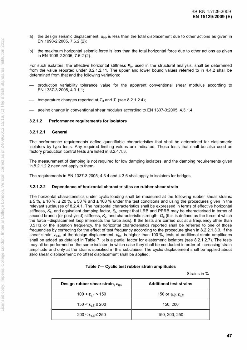
BS EN 15129:2009EN 15129:2009 (E)
47
a) the design seismic displacement, dbd, is less than the total displacement due to other actions as given in EN 1998-2:2005, 7.6.2 (2);
b) the maximum horizontal seismic force is less than the total horizontal force due to other actions as given in EN 1998-2:2005, 7.6.2 (2).
For such isolators, the effective horizontal stiffness Kb, used in the structural analysis, shall be determined from the value reported under 8.2.1.2.11. The upper and lower bound values referred to in 4.4.2 shall be determined from that and the following variations:
production variability tolerance value for the apparent conventional shear modulus according to EN 1337-3:2005, 4.3.1.1;
temperature changes reported at TU and TL (see 8.2.1.2.4);
ageing change in conventional shear modulus according to EN 1337-3:2005, 4.3.1.4.
8.2.1.2 Performance requirements for isolators
8.2.1.2.1 General
The performance requirements define quantifiable characteristics that shall be determined for elastomeric isolators by type tests. Any required limiting values are indicated. Those tests that shall be also used as factory production control tests are listed in 8.2.4.1.3.
The measurement of damping is not required for low damping isolators, and the damping requirements given in 8.2.1.2.2 need not apply to them.
The requirements in EN 1337-3:2005, 4.3.4 and 4.3.6 shall apply to isolators for bridges.
8.2.1.2.2 Dependence of horizontal characteristics on rubber shear strain
The horizontal characteristics under cyclic loading shall be measured at the following rubber shear strains: ± 5 %, ± 10 %, ± 20 %, ± 50 % and ± 100 % under the test conditions and using the procedures given in the relevant suclauses of 8.2.4.1. The horizontal characteristics shall be expressed in terms of effective horizontal stiffness, Kb, and equivalent damping factor, ξb, except that LRB and PPRB may be characterised in terms of second branch (or post-yield) stiffness, K2, and characteristic strength, Qd (this is defined as the force at which the force –displacement loop intersects the force axis). If the tests are carried out at a frequency other than 0,5 Hz or the isolation frequency, the horizontal characteristics reported shall be referred to one of those frequencies by correcting for the effect of test frequency according to the procedure given in 8.2.2.1.3.3. If the shear strain, εq,E, at the design displacement, dbd, is higher than 100 %, tests at additional strain amplitudes shall be added as detailed in Table 7. γb is a partial factor for elastomeric isolators (see 8.2.1.2.7). The tests may all be performed on the same isolator, in which case they shall be conducted in order of increasing strain amplitude and only at the strains specified in this subclause. The cyclic displacement shall be applied about zero shear displacement; no offset displacement shall be applied.
Table 7— Cyclic test rubber strain amplitudes Strains in %
Design rubber shear strain, εq,E Additional test strains
100 < εq,E ≤ 150 150 or γbγx εq,E
150 < εq,E ≤ 200 150, 200
200 < εq,E ≤ 250 150, 200, 250
Lice
nsed
cop
y: Im
peria
l Col
lege
Lon
don,
Impe
rial C
olle
ge L
ondo
n, V
ersi
on c
orre
ct a
s of
24/
09/2
012
15:1
6, (
c) T
he B
ritis
h S
tand
ards
Inst
itutio
n 20
12

BS EN 15129:2009EN 15129:2009 (E)
48
NOTE The test strain amplitudes are well spaced so that, if tests are performed on the same isolator, strain history effects are small.
The requirements are that:
the values of Kb and ξb (or K2 and Qd ) for the third cycle are reported for all the rubber shear strains tested;
if the design rubber shear strain is not included in the test strains listed, the values of Kb and ξb (or K2 and Qd) for the third cycle at the design rubber shear strain shall both be determined from the test results by linear interpolation;
the test frequency and reference frequency, if applicable, be reported;
the values of Kb and ξb (or K2 and Qd) for the third cycle at the design rubber shear strain shall both be within ± 20 % of the design value;
the value Kb at 5 % shear strain (or Qd) shall be sufficient to provide adequate restraint, as determined by the structural engineer, against wind loading.
A cyclic test to determine Kb and ξb (or K2 and Qd), performed at the shear strain amplitude listed in this subclause that is closest to the rubber shear strain, εq,E, at the design displacement, dbd, should be performed as a factory production control test with the requirement that the values of Kb and ξb (or K2 and Qd) for the third cycle shall both be within ± 20 % of the design value corrected, if necessary, for the difference between the test and design shear strain.
In the case that measurement of the cyclic horizontal characteristics at the shear strain amplitude listed in this subclause that is closest to the rubber shear strain, εq,E, at the design displacement, dbd, is not to be performed as a factory production control test, the following two tests shall be carried out as factory production control tests:
measurement of the horizontal secant stiffness under a one-sided ramp loading;
cyclic test to determine Kb and ξb (or K2 and Qd), performed at one of the lower shear strain amplitudes listed in this subclause. The shear strain amplitude shall be at least 20 %.
The ramp test shall also be performed as a type test in order to establish the requirement for the factory production control test. The isolator used for the cyclic tests shall be deformed up to the rubber shear strain listed in this subclause that is closest to the rubber shear strain, εq,E, at the horizontal design displacement, dbd. The ramp test shall be performed after the cyclic test at that strain and before the cyclic tests at higher strains. The other test conditions and procedures shall conform to the relevant parts of 8.2.4.1. The requirement in the type test is that the secant stiffness at the test shear strain shall be determined. The requirement of the ramp factory production control test is that the secant stiffness shall be within ± 20 % of the value determined from the type test, adjusted, if necessary, by the procedure given in 8.2.4.1.3 to allow for the difference between the design value of the cyclic stiffness Kb at the design displacement, dbd, and the value determined from the type tests. The requirement in the cyclic factory production control test is that the values of Kb and ξb (or K2 and Qd) for the third cycle shall both be within ± 20 % of the values obtained in the type test, the value of Kb (or K2 ) being adjusted, if necessary, by the procedure given in 8.2.4.1.3 to allow for the difference between the design value of the cyclic stiffness Kb (or K2 ) at the design displacement, dbd, and the value determined from the type tests.
8.2.1.2.3 Dependence of horizontal characteristics on frequency
The effect of frequency on horizontal characteristics Kb and ξb (or K2 and Qd) shall be determined by tests performed at a rubber shear strain amplitude of ± 100 %. The horizontal characteristics shall be measured at three frequencies. The recommended values are:
Lice
nsed
cop
y: Im
peria
l Col
lege
Lon
don,
Impe
rial C
olle
ge L
ondo
n, V
ersi
on c
orre
ct a
s of
24/
09/2
012
15:1
6, (
c) T
he B
ritis
h S
tand
ards
Inst
itutio
n 20
12

BS EN 15129:2009EN 15129:2009 (E)
49
0,1 Hz 0,5 Hz 2,0 Hz
Other values spaced by the same ratios may be chosen in agreement with the structural engineer. The tests shall be in order of increasing frequency.
The values of Kb and ξb (or K2 and Qd) for the third cycle shall be reported for each test frequency. The values at the lowest and highest frequency shall not differ by more than 20 % from the value at the middle frequency.
For HDRB and LDRB, the tests may be performed on isolators scaled without restriction, or may be substituted by the tests required in 8.2.2.1.3.3 on the elastomer used in its manufacture.
8.2.1.2.4 Dependence of horizontal characteristics on temperature
The changes in horizontal characteristics Kb and ξb (or K2 and Qd) between the upper and lower service temperatures, TU and TL respectively, shall be determined by tests under the conditions and using the procedures given in the relevant parts of 8.2.4.1. The horizontal characteristics shall be measured at a rubber shear strain amplitude of ± 100 % over a range of temperatures extending from at least TU to at least TL. A test at 23 °C shall be included. The tests shall be performed in order of decreasing temperature. It is recommended that tests at the following temperatures are included if they are within the range of service conditions:
40 °C, 23 °C, 0 °C, - 10 °C, - 20 °C
The values of Kb and ξb (or K2 and Qd) for the third cycle shall be reported for each test temperature. The values at the lowest temperature shall not differ by more than + 80 % or – 20 % from the corresponding values at 23 °C, and the values at the highest temperature shall not differ by more than ± 20 % from those at 23 °C.
For HDRB and LDRB, the tests may be performed on isolators scaled without restriction, or may be substituted by the tests required in 8.2.2.1.3.4 on the elastomer used in its manufacture.
8.2.1.2.5 Dependence of horizontal characteristics on repeated cycling
The horizontal characteristics Kb and ξb (or K2 and Qd) of the isolator shall be constant under repeated cyclic loading. The stability of the characteristics shall be verified by tests. The rubber shear strain amplitude shall be 100 % or the design shear strain if requested by the structural engineer. The other test conditions and procedures shall conform to those given in the relevant parts of 8.2.4.1. The requirement for constant characteristics Kb and ξb (or K2 and Qd) is met when:
the ratio between the minimum and maximum value of Kb (or K2) measured in the cycles between the second and the tenth shall not be less than 0,7;
the ratio between the minimum and maximum value of ξb (or Qd) measured in the cycles between the second and the tenth shall not be less than 0,7;
the ratio between the minimum and maximum value of Kb (or K2) measured in the cycles between the first and the tenth shall not be less than 0,6.
For HDRB and LDRB, the tests may be performed on isolators scaled without restriction, or may be substituted by the tests on the elastomer used in its manufacture as required in 8.2.2.1.3.6.
The requirements may refer to more than the tenth cycle if requested by the Structural Engineer.
8.2.1.2.6 Capacity in compression under zero lateral displacement
The isolator shall be able to support a vertical load equal to NSd [where in 8.2 NSd is the permanent load plus combination of non-seismic live load(s) according to EN 1990:2002, A.1 (for buildings) or A.2 (for bridges)]
Lice
nsed
cop
y: Im
peria
l Col
lege
Lon
don,
Impe
rial C
olle
ge L
ondo
n, V
ersi
on c
orre
ct a
s of
24/
09/2
012
15:1
6, (
c) T
he B
ritis
h S
tand
ards
Inst
itutio
n 20
12
BS EN 15129:2009EN 15129:2009 (E)
50
when zero lateral displacement is applied. This requirement shall be checked by applying a vertical load up to NSd and maintaining that load constant for at least 3 min whilst the isolator is examined for signs of failure. Other test conditions shall conform to the relevant parts of 8.2.4.1.
The requirement is that the load-displacement relation shall be monotonically increasing up to NSd, and that the isolator shall show no visual evidence of manufacturing imperfections or failure. The visual evidence referred to shall include:
signs of bond failure;
laterally misaligned or vertically misplaced reinforcing plates;
surface cracks or imperfections over 2 mm wide or deep.
NOTE See EN 1337-3:2005, 4.3.3 and the manufacturing tolerances given in EN 1337-3, Clause 6 for further guidance regarding the requirements.
8.2.1.2.7 Horizontal displacement capacity
The horizontal displacement capacity of an isolator shall be checked up to a displacement of γbdEd or a load of γbVEd, whichever is reached first (where VEd is the horizontal load corresponding to dEd) under the axial loads NEd,max and NEd,min
γb is a partial factor for elastomeric isolators, and its value shall be taken as 1,15.
The value of NEd,min shall not be a tension force producing a stress greater than 2G, where G is the shear modulus measured at 100 % strain (see 8.2.2.1.3.2).
NOTE 1 The value of the minimum vertical load may be tensile. The imposition of tensile stresses above the level specified here is avoided as cavitation of the rubber occurs at relatively low tensile hydrostatic stresses. A tensile stress of up to 2G is normally sustained without significant cavitation occurring. Special connections between the isolator and the structure that remove the possibility of the vertical load on the isolator becoming tensile can be used.
The test shall be carried out under a ramp input. The other test conditions shall conform to those given in the relevant parts of 8.2.4.1.
The requirements are that the load shall be monotonically increasing up to the maximum displacement and that the isolator shall not show any significant signs of failure at the end of the test. The visual evidence of failure referred to shall include:
signs of bond failure;
surface cracks or imperfections over 2 mm wide or deep.
The isolator connections to the load platens shall not show any signs of failure or yielding.
NOTE 2 See EN 1337-3:2005, 4.3.3 for further guidance regarding visual evidence of failure in the isolator.
If NEd,max differs from NEd,min by less than 20 % and the minimum load is compressive, only one test at the mean of the two loads needs to be performed; the same requirements shall be met.
8.2.1.2.8 Compression stiffness
The secant compression stiffness Kv of the isolator shall be determined between (1/3) NSd and NSd. The test conditions, equipment and other parts of the procedure shall conform to the relevant parts of 8.2.4.1.
The requirement is that Kv shall be reported. Lice
nsed
cop
y: Im
peria
l Col
lege
Lon
don,
Impe
rial C
olle
ge L
ondo
n, V
ersi
on c
orre
ct a
s of
24/
09/2
012
15:1
6, (
c) T
he B
ritis
h S
tand
ards
Inst
itutio
n 20
12

BS EN 15129:2009EN 15129:2009 (E)
51
This test shall also be used as a factory production control test. The requirement is that Kv shall be within ± 30 % of the value determined in the type test, and the visual inspection at the maximum load shall show no signs of imperfection or failure as given in the requirements in 8.2.1.2.6.
NOTE The force-deflection curve at low loads generally has a low gradient. This phenomenon, termed lead-in or bedding down, is caused by the slight misalignment of the top and bottom bearing surfaces normally present.
8.2.1.2.9 Effect of ageing
The changes in the horizontal characteristics Kb and ξb of the isolator (or K2 only for LRB manufactured using low damping elastomer) shall be estimated to be less than 20 % over the expected service life of the isolator. The estimated change shall be determined by accelerated ageing tests on the elastomer material of the isolator (see 8.2.2.1.3.5), and by reference to any available directly relevant service life data on devices fabricated from similar materials. For PPRB, ageing tests on the polymer plug material shall also be performed according to 8.2.2.1.3.5 so that its contribution to the change in Kb and ξb can be estimated. Unless requested otherwise by the Structural Engineer, the requirement in this subclause is deemed to be met if the elastomer material (and polymer plug material if applicable) satisfies the requirement in 8.2.2.1.3.5 under the standard ageing conditions (14 days at 70 ºC) given there.
NOTE The service life of anti-seismic devices is discussed in Annex B. For elastomeric isolators, it can be expected to be 60 years.
8.2.1.2.10 Effect of creep
The short-term creep deformation produced by the design vertical load for non-seismic conditions, NSd, may be measured, if requested by the Structural Engineer, in the case of HDRB and PPRB. The conditions and procedures shall conform to those given in the relevant subclauses of 8.2.4.1.
NOTE 1 It is recommended that the percentage creep between 10 min and 104 min (approximately one week) should be less than 20 % of the deformation after 10 min unless otherwise agreed by the Structural Engineer.
NOTE 2 The recommendation should ensure that deformation of the isolator does not increase excessively over time under the action of the gravity loads supported.
8.2.1.2.11 Low damping bridge isolators subjected to small seismic actions
1) The requirements given in 8.2.1.2.2, 8.2.1.2.4 and 8.2.1.2.7, as modified by this subclause, shall apply in addition to the requirements of EN 1337-3:2005.
2) In EN 1337-3:2005 5.3.3.3, the design shear strain due to translational movements shall be evaluated including the design displacement dbd without the reliability factor γx applied.
3) The requirements given in 8.2.1.2.2 shall be modified so that only the effective horizontal stiffness, Kb, shall be measured at one rubber shear strain agreed with the Structural Engineer. The five requirements listed in 8.2.1.2.2 are replaced by:
the value of Kb for the third cycle be reported;
the test frequency and reference frequency, if applicable, be reported.
4) The rubber shear strain amplitude for requirement 8.2.1.2.4 shall be agreed with the structural engineer.
5) If the rubber shear strain corresponding to the horizontal displacement γbdEd is ≤ 200 %, the requirement in 8.2.1.2.7 shall be deemed to have been met by satisfying EN 1337-3:2005, 4.3.2.1.
Lice
nsed
cop
y: Im
peria
l Col
lege
Lon
don,
Impe
rial C
olle
ge L
ondo
n, V
ersi
on c
orre
ct a
s of
24/
09/2
012
15:1
6, (
c) T
he B
ritis
h S
tand
ards
Inst
itutio
n 20
12
BS EN 15129:2009EN 15129:2009 (E)
52
8.2.1.3 Structural and mechanical requirements
8.2.1.3.1 Requirements at ULS
The isolator shall be verified to meet the requirements at ULS given in 4.1.4 by its satisfying the lateral capacity test requirement of 8.2.1.2.7, the maximum total design shear strain of 8.2.3.4.2, and the stability criterion of 8.2.3.4.4 (in the case of bolted isolators) or 8.2.3.4.5 (in the case of recessed or dowelled isolators). A low damping bridge isolators subjected to small seismic actions shall be verified to meet the requirements at ULS given in 4.1.4 by satisfying the lateral capacity test requirement of 8.2.1.2.11, the maximum total design shear strain of 8.2.3.4.2, and the stability criterion of 8.2.3.4.4 (in the case of bolted isolators) or 8.2.3.4.5 (in the case of recessed or dowelled isolators).
8.2.1.3.2 Requirements at SLS
Because the requirements at ULS introduced by 8.2.1.3.1 ensure serviceability under that condition, the requirements at SLS given in 4.1.4 are satisfied.
8.2.2 Materials
8.2.2.1 Elastomers
8.2.2.1.1 General
The requirements given in 8.2.2.1 apply to the elastomer used to fabricate the laminated part of the isolator.
The raw elastomers used shall be virgin material; no reclaimed or reground vulcanized rubber shall be used.
The elastomer shall have a shear modulus at a shear strain of 100 % within the range 0,3 MPa to 1,5 MPa.
The vulcanised elastomer shall meet the requirements given in 8.2.2.1.
The tests to determine the quantifiable characteristics to which the requirements refer shall all be performed as type tests. Tests that shall be used as factory production control tests are listed in 8.2.4.2.3.
The test methods and test pieces shall conform to the relevant subclauses in 8.2.4.2.
Low damping elastomers for bridge isolators subjected to small seismic inputs (see 8.2.1.1) need conform only to EN 1337-3:2005; they are not subject to the requirements of 8.2.2.1.
NOTE 1 Some of the requirements differ depending on whether samples are moulded from the device compound or taken from a complete finished device.
NOTE 2 The mechanical property requirements (tensile strength, elongation at break and tear resistance) to be met in 8.2.2.1.2.1 and 8.2.2.1.2.2 are to confirm the general suitability of the elastomer; these properties are not directly related to the performance of the isolator. The compression set test provides a check that the elastomer is adequately vulcanised. The remaining tests (ozone resistance and accelerated ageing in air) provide a check that suitable antidegradants have been included in the compound.
8.2.2.1.2 General properties
8.2.2.1.2.1 Low damping elastomers
Low damping elastomers used in isolators for bridges shall conform to EN 1337-3:2005, 4.4.1. All low damping elastomers, except those for bridge isolators subjected to small seismic inputs (see 8.2.1.1), shall also conform to the material requirements in Table 8. The tests shall be carried out as type tests and factory production control tests. Li
cens
ed c
opy:
Impe
rial C
olle
ge L
ondo
n, Im
peria
l Col
lege
Lon
don,
Ver
sion
cor
rect
as
of 2
4/09
/201
2 15
:16,
(c)
The
Brit
ish
Sta
ndar
ds In
stitu
tion
2012
BS EN 15129:2009EN 15129:2009 (E)
53
8.2.2.1.2.2 High damping elastomers
High damping elastomers shall meet the requirements given in Table 9. The tests shall be carried out as type tests and production control tests.
NOTE Bearings based primarily on natural rubber or polychloroprene rubber have been used as structural bearings for several decades and in most cases have performed to requirements. Isolators fabricated from these two elastomers may therefore be expected to have a long service life. Moreover, natural rubber and polychloroprene rubber crystallise under applied strain, a phenomenon making them resistant to the enlargement of surface cracks under the applied gravity load. For high damping isolators, other elastomers are not excluded by this subclause, but their use necessitates particular consideration of ageing performance and resistance to the growth of surface cracks.
8.2.2.1.3 Dynamic shear modulus and damping
8.2.2.1.3.1 General
The dynamic testing of the elastomer and the evaluation of the results shall be carried out according to the methods and procedures of 8.2.4.2.5.
NOTE The measurement of damping is not required for low damping elastomers [(ξb(100 %) ≤ 0,06)], and the damping requirements given in 8.2.2.1.3 do not apply to them.
Lice
nsed
cop
y: Im
peria
l Col
lege
Lon
don,
Impe
rial C
olle
ge L
ondo
n, V
ersi
on c
orre
ct a
s of
24/
09/2
012
15:1
6, (
c) T
he B
ritis
h S
tand
ards
Inst
itutio
n 20
12

BS EN 15129:2009EN 15129:2009 (E)
54
Table 8 — Mechanical and physical properties of low damping elastomers
Property Requirement
Test Method
Shear modulusa (MPa) 0,3 ≤ G ≤ 0,7 0,7 < G ≤ 1,1 1,1 < G ≤ 1,5
Tensile strength (MPa), min. Moulded test piece
Test piece from bearingb
16 14
ISO 37 Type 2
Elongation at break (%), min. Moulded test piece
Test piece from bearingb
450 400
425 375
350 300
"
Tear resistancec (kN/m), min.
5 8 10 ISO 34g Method A
Compression setd
30
30
30 ISO 815 Type A
70 °C, 24 h, max. 25% compression
Ozone resistancee no cracks
no cracks
no cracks
ISO 1431-1 Elongation 30 % - 96 h
40 °C ± 2 °C Accelerated air oven ageingf
ISO 188, Method A
Maximum change from unaged value
Hardness (IRHD) -5, +8 ± 15
± 25
-5, +8 ± 15
± 25
-5, +8 ± 15
± 25
ISO 48 Tensile strength (%) ISO 37 Type2 Elongation at break (%) “
NOTE Because the ozone and ageing tests are checks that appropriate antidegradants have been included, not tests related to service performance, their effectiveness necessitates that the conditions should be appropriate to the elastomer used in manufacture of the devices. a Measured at 100 % shear strain amplitude at 23 oC.
b Test pieces from complete finished isolators shall be taken from the first internal layer and from the layer at the centre of the isolator. c The values are those for a natural rubber based compound. A polychloroprene based compound shall give values 20 % higher. Other elastomers shall meet the requirements for a natural rubber based compound.
d The value is that for a natural rubber based compound. A polychloroprene based compound shall give a value 50 % lower. For other elastomers, the values shall be agreed between the manufacturer and the structural engineer.
e The ozone concentration shall be appropriate to the elastomer used. For natural rubber based vulcanisates, 25 pphm shall be used and for polychloroprene based vulcanisates 100 pphm. For other elastomers, the values shall be agreed between the manufacturer and the structural engineer. For elastomers with no unsaturated carbon-carbon bonds, an ozone test need not be performed. f Ageing condition shall be chosen appropriate to elastomers used. For natural rubber based vulcanisates, 7 days at 70 °C shall be used and for polychloroprene based vulcanisates, 3 days at 100 °C. For other elastomers, the values shall be agreed between the manufacturer and the structural engineer. g If the legs of the test piece extend without the initial cut growing , the method shall be modified to reduce the extension and ensure cut growth by either increasing the width of the legs or fixing a flexible but relatively inextensible reinforcement to the test piece; the reinforcement shall leave a gap of 5mm where the tear is expected to grow. Li
cens
ed c
opy:
Impe
rial C
olle
ge L
ondo
n, Im
peria
l Col
lege
Lon
don,
Ver
sion
cor
rect
as
of 2
4/09
/201
2 15
:16,
(c)
The
Brit
ish
Sta
ndar
ds In
stitu
tion
2012

BS EN 15129:2009EN 15129:2009 (E)
55
Table 9 — Mechanical and physical properties of high damping elastomers
Property
Requirement
Test Method Moulded Sample Test piece from
deviced
Tensile strength (MPa), min. 12 10 ISO 37 Type 2
Elongation at break (%), min. 400 350 "
Tear resistance (kN/m), min. 7 ISO 34c Method A
Compression set
60
ISO 815 Type A
70 °C, 24 h, max. 25% compression
Ozone resistancea
no cracks
Elongation 30 % - 96 h ISO 1431-1
40 °C ± 2 °C
Accelerated air oven ageingb ISO 188, Method A
Maximum change from
unaged value
Hardness (IRHD) -5, +8
± 15
± 25
ISO 48
Tensile strength (%) ISO 37 Type 2
Elongation at break (%) "
NOTE Because the ozone and ageing tests are checks that appropriate antidegradants have been included, not tests related to service performance, their effectiveness necessitates that the conditions should be appropriate to the elastomer used in manufacture of the devices.
a The ozone concentration shall be appropriate to the elastomers used. For natural rubber based vulcanisates, 25 pphm shall be used and for polychloroprene based vulcanisates 100 pphm. For other elastomers, the values shall be agreed between the manufacturer and the structural engineer. For elastomers with no unsaturated carbon-carbon bonds, an ozone test need not be performed.
b Ageing condition shall be chosen appropriate to elastomers used. For natural rubber based vulcanisates, 7 days at 70 °C shall be used and for polychloroprene based vulcanisates, 3 days at 100 °C. For other elastomers, the values shall be agreed between the manufacturer and the structural engineer.
c If the legs of the test piece extend without the initial cut growing, the method shall be modified to reduce the extension and ensure cut growth by either increasing the width of the legs or fixing a flexible but relatively inextensible reinforcement to the test piece; the reinforcement shall leave a gap of 5 mm where the tear is expected to grow.
d Test pieces from complete finished isolators shall be taken from the first internal layer and from the layer at the centre of the isolator.
Lice
nsed
cop
y: Im
peria
l Col
lege
Lon
don,
Impe
rial C
olle
ge L
ondo
n, V
ersi
on c
orre
ct a
s of
24/
09/2
012
15:1
6, (
c) T
he B
ritis
h S
tand
ards
Inst
itutio
n 20
12

BS EN 15129:2009EN 15129:2009 (E)
56
8.2.2.1.3.2 Effect of strain amplitude
The elastomer vulcanisate shall be dynamically tested over a range of rubber shear strains. The recommended frequency is 0,5 Hz, though another may be requested by the structural engineer. Measurements shall be made at the following shear strain amplitudes:
5 %,10 %, 20 %, 50 %,100 %, and 150 %
If the strain at the design displacement, dbd, is over 100 %, tests at additional strain amplitudes shall be added as detailed in Table 10.
The tests shall be performed in ascending order of strain amplitude.
The shear modulus and equivalent damping factor shall be reported for the third cycle for each strain amplitude.
Table 10 — Cyclic test strain amplitudes
Design rubber shear strain, εq,E (%)
Additional test strain
(%)
100 <εq,E ≤ 150 200
150 <εq,E ≤ 200 200, 250
200 <εq,E ≤ 250 200, 250, 300
8.2.2.1.3.3 Effect of frequency
The effect of frequency shall be determined by measurements at three frequencies at a shear strain amplitude of ± 100 %. The tests shall be in order of increasing frequency. The following are the recommended values:
0,1 Hz 0,5 Hz 2,0 Hz
Other values spaced by the same ratios may be chosen in agreement with the structural engineer. The shear modulus and damping for the third cycle shall be reported at each test frequency. The modulus and damping at the lowest and highest frequencies shall not differ by more than 20 % from the value at the middle frequency.
If any of the isolators are to be tested at a frequency other than 0,5 Hz or the isolation frequency, the isolator test frequency shall be included in the tests of this subclause, whilst retaining the pattern of testing in ascending order of frequency.
The ratio between the rubber shear modulus at the reference frequency (0,5 Hz or the isolation frequency) and the rubber shear modulus at the isolator test frequency shall be applied to the isolator stiffness measurements (for the same rubber shear strain) to correct them for the effect of frequency, and thus determine a value of isolator stiffness at that strain appropriate to the reference frequency as mentioned in 8.2.1.2.2. The same procedure shall be used to correct the damping measurement on the isolator for the effect of frequency, and thus determine a value of isolator damping appropriate to the reference frequency.
8.2.2.1.3.4 Effect of temperature
The rubber dynamic shear modulus and damping shall be measured for a shear strain amplitude of ± 100 % and at the reference frequency (0,5 Hz or the isolation frequency) over a range of temperatures extending from at least the upper service temperature, TU, to at least the lower service temperature TL. A test at 23 °C
Lice
nsed
cop
y: Im
peria
l Col
lege
Lon
don,
Impe
rial C
olle
ge L
ondo
n, V
ersi
on c
orre
ct a
s of
24/
09/2
012
15:1
6, (
c) T
he B
ritis
h S
tand
ards
Inst
itutio
n 20
12
BS EN 15129:2009EN 15129:2009 (E)
57
shall be included. The tests shall be performed in order of decreasing temperature. It is recommended that tests at the following temperatures be included if they are within the range of service conditions:
40 °C, 23 °C, 0 °C, - 10 °C, - 20 °C
The values of dynamic shear modulus and damping for the third cycle shall be reported for each test temperature. The values at the lowest temperature shall not differ by more than + 80 % or – 20 % from the corresponding values at 23 °C, and the values at the highest temperature shall not differ by more than ± 20 % from those at 23 °C.
8.2.2.1.3.5 Shear modulus and damping after accelerated anaerobic ageing
The dynamic shear modulus and damping shall be measured both before ageing and after ageing for 14 days at 70 °C. If moulded test pieces are used, the same one shall be tested un-aged and aged. The ageing shall be carried out in anaerobic conditions and such that volatile compounding ingredients shall not be lost. The modulus and damping measurements shall be carried out at a shear strain amplitude of ± 100 %, and the reference frequency (0,5 Hz or the isolation frequency).
The shear modulus and equivalent damping factor shall have changed by less than 20 % due to the ageing.
The Structural Engineer may request that ageing conditions equivalent to a period of 60 years at the average service temperature be estimated for the elastomer compound and those ageing conditions be substituted for those above; an ageing temperature above 70 °C shall not be used.
NOTE See informative Annex F, F.1 for guidance on the determination of ageing conditions equivalent to a period of 60 years, and recommendations for achieving anaerobic conditions.
8.2.2.1.3.6 Stability of shear properties under repeated cycling
The shear modulus, G, and equivalent damping factor, ξ, of the elastomer shall be stable under repeated cyclic loading. This requirement is met when:
the ratio between the minimum and maximum value of G measured in the cycles between the second and the tenth shall not be less than 0,7;
the ratio between the minimum and maximum value of ξ measured in the cycles between the second and the tenth shall not be less than 0,7;
the ratio between the minimum and maximum value of G measured in the cycles between the first and the tenth shall not be less than 0,6.
The shear strain amplitude shall be 100 % or the design shear strain if requested by the structural engineer. The other test conditions and procedures shall conform to those given in the relevant parts of 8.2.4.2.5.
The requirements may refer to more than the tenth cycle if requested by the Structural Engineer.
8.2.2.1.4 Shear bond test
8.2.2.1.4.1 Unaged
The shear strength of the steel-elastomer bond shall be checked on unaged test pieces according to the test described in 8.2.4.2.5.3.
The force-displacement curve shall be monotonically increasing, and the test piece shall show no signs of failure or de-bonding. The test report shall conform to 8.2.4.2.5.3.
Lice
nsed
cop
y: Im
peria
l Col
lege
Lon
don,
Impe
rial C
olle
ge L
ondo
n, V
ersi
on c
orre
ct a
s of
24/
09/2
012
15:1
6, (
c) T
he B
ritis
h S
tand
ards
Inst
itutio
n 20
12

BS EN 15129:2009EN 15129:2009 (E)
58
8.2.2.1.4.2 Aged
The test described in 8.2.2.1.4.1 shall be performed on three test pieces aged 14 days at 70 °C. The ageing shall be carried out in anaerobic conditions and such that volatile compounding ingredients shall not be lost. The Structural Engineer may request that ageing conditions equivalent to a period of 60 years at the average service temperature be estimated for the elastomer compound and those ageing conditions be substituted for those above; an ageing temperature above 70 °C shall not be used.
The force-displacement curve shall be monotonically increasing, and the test piece shall show no signs of failure or de-bonding. The test report shall conform to 8.2.4.2.5.3.
NOTE See informative Annex F, F.1 for guidance on the determination of ageing conditions equivalent to a period of 60 years, and recommendations for achieving anaerobic conditions.
8.2.2.1.5 Resistance to low temperature crystallisation
The resistance to low temperature crystallization shall be checked for elastomers susceptible to this phenomenon (e.g. natural rubber, polychloroprene rubber and certain types of ethylene propylene) if the minimum frequently occurring service temperature falls within the range where crystallization may occur. High damping [(ξ(100 %) > 0,06)] natural rubber shall be checked for minimum frequently occurring service temperatures, lower than 0 ºC, low damping natural rubber for minimum service temperatures lower than – 5 ºC and polychloroprene for minimum service temperatures lower than 5 ºC.
NOTE Because of the nature of low temperature crystallisation the minimum frequently occurring temperature may not be equal to TL.
A shear test piece shall be used, and the test procedure given in 8.2.4.2.5.4 shall be followed.
The requirement is that the shear stiffness at shear strains of 25 % and 100 % following the required exposure to low temperature shall both be reported. They shall both be less than 1,5 times the respective shear stiffness before exposure.
The test shall be performed as a type test.
8.2.2.1.6 Resistance to slow crack growth
The following test shall be performed on three moulded samples using the geometry of ISO 34 Method A:
Test: apply load equivalent to 4 kN/m
and the following requirement satisfied:
the initial cut shall not extend in any direction by more than 3 mm in < 24 h of loading.
8.2.2.2 Polymer plug
The plug material used to provide damping in PPRB shall meet the requirements given in 8.2.2.1.3 and 8.2.2.1.5, except that regarding 8.2.2.1.3.2 there shall be no restriction on the permitted range of shear modulus.
8.2.2.3 Lead plug
The lead shall be of purity ≥ 99,9 %.
Lice
nsed
cop
y: Im
peria
l Col
lege
Lon
don,
Impe
rial C
olle
ge L
ondo
n, V
ersi
on c
orre
ct a
s of
24/
09/2
012
15:1
6, (
c) T
he B
ritis
h S
tand
ards
Inst
itutio
n 20
12
BS EN 15129:2009EN 15129:2009 (E)
59
8.2.2.4 Reinforcing steel plates
The inner reinforcing and end plates used in the manufacture of elastomeric isolators shall meet the requirements given by EN 1337-3:2005, 4.4.3.
8.2.3 Design
8.2.3.1 General
Elastomeric isolators, including low damping isolators shall be designed to meet the relevant provisions of:
this subclause corresponding to load combinations including the seismic action;
subclauses 5.1, 5.2 and 5.3.3 of EN 1337-3:2005 at load combinations not including the seismic action, unless otherwise specified in this subclause.
The parameter Ar , the reduced effective plan area due to the horizontal displacement of the top of the bearing relative to the bottom [see EN 1337-3:2005, equation (9)], shall only take account of non-seismic horizontal displacements.
8.2.3.2 Types and shapes of isolators
The isolator shall consist of alternate layers of elastomer and steel; in each case the layers shall be nominally identical. It shall be moulded under appropriate conditions of heat and pressure, and the steel plates hot-bonded to the elastomer during vulcanization. Two thick end plates shall be hot bonded to the rest of the isolator. The sides of the isolator, possibly excluding the sides of the end plates in the case of isolators located in a recess, shall be covered with a rubber layer at least 4 mm thick. Unless the cover layer provides fire resistance, it shall consist of the same material as that in the bulk of the isolator and be cured at the same time as the main body of the isolator.
NOTE The two standard fixing methods for bolted elastomeric isolators are shown in Figure 3; recess or dowel fixing methods may be used by agreement of the Structural Engineer.
Bearings types shall be only rectangular or circular. It is permissible to include holes of uniform section in the loaded area. The holes may be plugged with lead or other material to provide additional damping.
Table 3 of EN 1337-3:2005 shall not apply to elastomeric isolators.
Lice
nsed
cop
y: Im
peria
l Col
lege
Lon
don,
Impe
rial C
olle
ge L
ondo
n, V
ersi
on c
orre
ct a
s of
24/
09/2
012
15:1
6, (
c) T
he B
ritis
h S
tand
ards
Inst
itutio
n 20
12
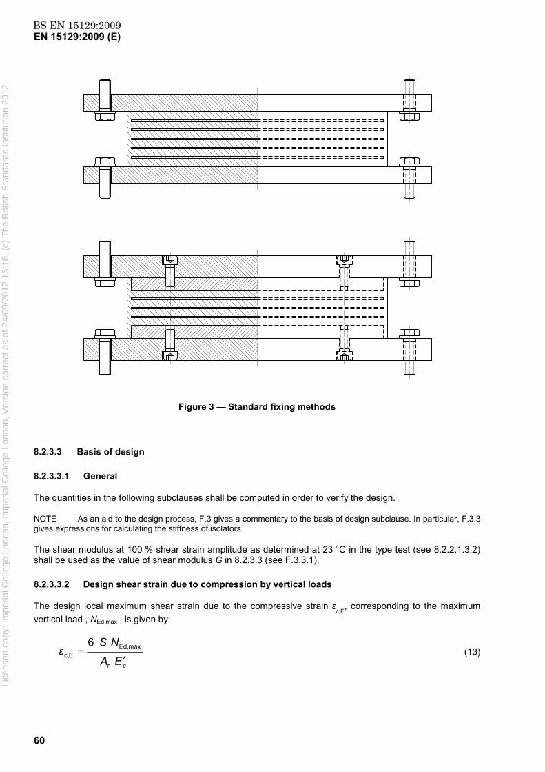
BS EN 15129:2009EN 15129:2009 (E)
60
Figure 3 — Standard fixing methods
8.2.3.3 Basis of design
8.2.3.3.1 General
The quantities in the following subclauses shall be computed in order to verify the design.
NOTE As an aid to the design process, F.3 gives a commentary to the basis of design subclause. In particular, F.3.3 gives expressions for calculating the stiffness of isolators.
The shear modulus at 100 % shear strain amplitude as determined at 23 °C in the type test (see 8.2.2.1.3.2) shall be used as the value of shear modulus G in 8.2.3.3 (see F.3.3.1).
8.2.3.3.2 Design shear strain due to compression by vertical loads
The design local maximum shear strain due to the compressive strain εc,E
, corresponding to the maximum vertical load , NEd,max , is given by:
c
x
EA
NSε
′=
r
maEd,Ec,
6 (13)
Lice
nsed
cop
y: Im
peria
l Col
lege
Lon
don,
Impe
rial C
olle
ge L
ondo
n, V
ersi
on c
orre
ct a
s of
24/
09/2
012
15:1
6, (
c) T
he B
ritis
h S
tand
ards
Inst
itutio
n 20
12

BS EN 15129:2009EN 15129:2009 (E)
61
S, the shape factor of the rubber layers, is the ratio between the effective loaded area and the force free area. Thus for circular isolators with internal reinforcing plates of diameter D´ and rubber layer thickness tr :
rt
DS4
′= (14)
Holes shall be considered in calculating the effective loaded area and the force free area, but holes that are tightly plugged shall be ignored (see F.3.1 for other examples of formulae for the shape factor.)
Ar is the reduced effective plan area due to non-seismic actions only (e.g. thermally induced actions).
E ΄c for rectangular devices, circular devices and annular devices with plugged hole is:
( )2'c 21 3 SGE += (15)
The expression for E´c for annular devices with unplugged hole is given in F.3.3.4.
NOTE Equation (13) can be derived by linear elastic analysis of rubber layers. It is reasonably accurate (it gives an underestimate of up to 10 %) for S ≤ 8; in this context no correction for the effect of bulk compressibility is made. See F.3.2. The factor 1,5 in equation (5.7) of EN 1337-3:2005 for calculation of, εc,E, is not supported by the analysis.
8.2.3.3.3 Design shear strain due to earthquake-imposed horizontal displacement
The design shear strain, εq,E, due to the earthquake-imposed design displacement d bd , is given by:
q
bdEq, T
d=ε (16)
where Tq is the total thickness of the elastomer active during shear.
8.2.3.3.4 Buckling load at zero lateral seismic displacement
The buckling load for devices with a shape factor, S > 5 is given by the expression:
q
rcr
'λT
SaGAP = (17)
where, for rectangular devices, a' is the effective width of the device, i.e. the length of the smaller side of the internal reinforcing plates and λ equals 1,3. For circular devices a´ is the effective diameter D´ of the device, i.e. the diameter of the internal reinforcing plates and λ equals 1,1. For bearings with holes, plugged or unplugged, Ar shall exclude the area of the holes.
NOTE See the reference given in F.3.2 for origin of Equation (17).
8.2.3.4 Design criteria
8.2.3.4.1 Design Shear Strain
The shear strain, εq,max, due to the maximum horizontal displacement, dbd, shall be less than 2,5, i.e.:
2,5maxq, ≤ε (18) Lice
nsed
cop
y: Im
peria
l Col
lege
Lon
don,
Impe
rial C
olle
ge L
ondo
n, V
ersi
on c
orre
ct a
s of
24/
09/2
012
15:1
6, (
c) T
he B
ritis
h S
tand
ards
Inst
itutio
n 20
12

BS EN 15129:2009EN 15129:2009 (E)
62
The requirement in EN 1337-3:2005, 5.3.3.3 shall apply to non-seismic actions.
8.2.3.4.2 Maximum Total Design Shear Strain
The requirement and definitions given here shall replace those in EN 1337-3:2005, 5.3.3 (a) except where stated otherwise.
The maximum total design shear strain εt,d is given by the expression:
)( d,max q, Ec,L dt, αεεεε ++= K (19)
where εc,E is given by Equation (13),
εα,d is given by EN 1337-3:2005, 5.3.3.4. A minimum rotation angle of 0,003 rad shall be assumed for each orthogonal direction in calculating εα,d.
KL is a type loading factor, which shall be unity except for isolators used to support bridges. In that case the value shall conform to EN 1337-3:2005, Annex C.
The maximum total design shear strain as defined here shall satisfy the requirement:
mγ≤ε 0,7 dt, (20)
where γm is partial factor for elastomer material. It is recommended that the value of γm is taken as 1,0.
NOTE EN 1998-2 introduces γm as NDP and recommends a value 1,15. EN 1337-3:2005 recommends a value of 1,0 for the same parameter.
8.2.3.4.3 Reinforcing plate thickness
The specifications given in EN 1337-3:2005, 5.3.3.5 shall be fulfilled, but with the reduced area Ar calculated taking into account only the non-seismic displacements (i.e. due to thermal variations, shrinkage, etc.) and with Kh = 1 if there is only a central hole. For other holes, whether plugged or unplugged, Kh = 2.
8.2.3.4.4 Buckling stability under seismic actions
This subclause shall not apply to lead rubber bearings provided that the diameter of the lead plug exceeds 15 % of the minimum plan dimension. In case of multiple lead cores, the diameter of the equivalent single lead core is taken into account.
NEd,max < Pcr/2 (21)
For 42cr
maxEd,cr P
NP
≥> , the following condition shall be satisfied:
δ7,02
1cr
maxEd, ≥−P
N (22)
and for 4cr
maxEd,P
N < the following condition shall be satisfied:
7,0≤δ (23) Lice
nsed
cop
y: Im
peria
l Col
lege
Lon
don,
Impe
rial C
olle
ge L
ondo
n, V
ersi
on c
orre
ct a
s of
24/
09/2
012
15:1
6, (
c) T
he B
ritis
h S
tand
ards
Inst
itutio
n 20
12

BS EN 15129:2009EN 15129:2009 (E)
63
where ad
′= Edδ .
NOTE The parameter a' is defined in 8.2.3.3.4.
8.2.3.4.5 Roll-over stability under seismic actions
If recessed isolators or isolators with dowel connection are used by agreement of the Structural Engineer, instead of the standard fixing methods specified in 8.2.3.2, the roll-over stability shall be checked using the following relation:
( )minEd,bb
minEd,
REd
1NTKaN
d+
′⋅≤
γ (24)
where
NEd,min is the minimum vertical force at the design seismic situation;
Kb is the horizontal shear stiffness measured at the largest test displacement;
Tb is the total height of the device;
and γR is a partial factor, the recommended value of which is 1,5.
NOTE The parameter a' is defined in 8.2.3.3.4.
8.2.4 Testing
8.2.4.1 Isolators
8.2.4.1.1 General
The tests in this subclause shall be carried out on the elastomeric isolator to demonstrate the satisfaction of the requirements specified in 8.2.1.2.
The test isolators shall be conditioned at the test temperature for at least 24 h. Test isolators with a total rubber thickness > 250 mm shall be tested at least 48 h after the completion of moulding. The tests shall be performed on isolators not subjected to any scragging, unless they are to be supplied after scragging. In that case, the test isolators shall be subjected to the same scragging procedure as the production isolators. Evidence shall be provided that the change in characteristic values produced by the scragging is permanent. The test isolator shall not have been subjected to any previous tests, except that more than one of the tests in this clause may be performed on an isolator, provided the order of the tests conforms to 8.2.4.1.4.
NOTE Scragging is a term used by rubber technologists to mean the application of several, generally large, cycles of deformation to a rubber device. Such scragging reduces the stiffness of the device for subsequent deformations smaller than that used for the scragging. It is sometimes assumed that the changes of stiffness produced are permanent; there is, however, generally a significant recovery of the stiffness back to the original value. The recovery is initially relatively rapid, but the later stages may occur over months or years.
The tests shall be performed at a temperature of (23 ± 5) °C, unless some other temperature is specified in the following subclauses.
Each test report shall include the statement that the test was carried according to this standard.
Lice
nsed
cop
y: Im
peria
l Col
lege
Lon
don,
Impe
rial C
olle
ge L
ondo
n, V
ersi
on c
orre
ct a
s of
24/
09/2
012
15:1
6, (
c) T
he B
ritis
h S
tand
ards
Inst
itutio
n 20
12

BS EN 15129:2009EN 15129:2009 (E)
64
8.2.4.1.2 Type Testing
The type tests listed in Table 11 shall be performed on the minimum number of samples specified in 8.2.4.1.4, according to the methods specified in 8.2.4.1.5. For low damping bridge isolators subjected to small seismic actions, only the tests marked with an asterisk in Table 11 are required as type tests by this European Standard; the type tests in EN 1337-3 shall be performed for such isolators.
For those tests required to be performed on an isolator, it shall be full-scale, except the tests on LRB and PPRB to determine the influence of frequency, temperature and repeated cycling on the horizontal characteristics may use isolators scaled according to the following rules:
isolators of plan dimension ≤ 500 mm shall be tested full-scale;
for larger isolators, linear dimensions may be reduced by factor up to maximum of 2. All dimensions shall be scaled by same factor. Minimum allowed plan dimension for bearing after scaling is 500 mm.
The following modifications to an isolator shall require a new set of type tests:
a) different elastomer compound;
b) variation of the shape factor of the elastomer layers of more than 10 % with respect to that of a device already tested;
c) increase of any external dimension of the isolator or of the plan dimension of the internal reinforcing plates of more than 10 %;
d) decrease of any external dimension of the isolator or of the plan dimension of the internal reinforcing plates of more than 50 %
e) a different type of attachment system is used;
f) different moulding conditions are used.
NOTE In e) the term ‘different types of attachment system’ refers to bolted, recess or dowelled.
Any smaller differences in the design of the isolator shall require the following type tests to be carried out to provide reference values for the factory production control tests:
g) compression stiffness (8.2.1.2.8);
h) horizontal stiffness and damping at the two rubber shear strains given in 8.2.1.2.2 that bracket the design rubber shear strain, εq,E.
An extension of the ranges of use of a particular isolator type beyond those covered by previous type tests shall require additional type tests to be performed. Extensions of use shall include the following:
i) increase of εq,E sufficient to necessitate additional cyclic tests according to Table 10;
j) increase of upper service temperature by more than 5 °C;
k) decrease of lower service temperature by more than 3 °C;
l) increase of the permanent load plus combination of non-seismic live loads, NSd, by more than 30 %;
m) increase of γbdEd, by more than 5 %;
n) increase of maximum vertical load including effect of seismic actions, NEd,max, by more than 10 %; Lice
nsed
cop
y: Im
peria
l Col
lege
Lon
don,
Impe
rial C
olle
ge L
ondo
n, V
ersi
on c
orre
ct a
s of
24/
09/2
012
15:1
6, (
c) T
he B
ritis
h S
tand
ards
Inst
itutio
n 20
12

BS EN 15129:2009EN 15129:2009 (E)
65
o) decrease of minimum vertical load including effect of seismic actions, NEd,min, by more than 0,1 NSd or by amount sufficient to change NEd,min from compressive to tensile.
Table 11 — Isolator testing and requirements
Test Type test requirements Factory production control test
requirements
Capacity in compression under zero lateral displacement
Support NSd . No defects visible. See 8.2.1.2.6.
N/A
Compression stiffness
Report value. See 8.2.1.2.8. Within ±30% of type test value. No defects
visible. See 8.2.1.2.8
*Horizontal characteristics Kb and ξb (or K2 and Qd) under
cyclic deformation
Report strain dependence. At design displacement, dbd,
values within ±20% of design value. See 8.2.1.2.2
Values within ±20% of required values. See 8.2.1.2.2
*Horizontal stiffness under a one-sided ramp loading
(Required if cyclic horizontal stiffness and damping from production control test not measured at shear strain amplitude close to value
corresponding to, dbd)
Report value at design displacement, dbd.
See 8.2.1.2.2
Within ± 20 % of adjusted type test value. See 8.2.1.2.2
Variation of horizontal characteristics Kb and ξb (or K2
and Qd) with frequency
Report variation. Maximum variation ± 20 %. See
8.2.1.2.3 N/A
*Variation of horizontal characteristics Kb and ξb (or K2
and Qd) with temperature
Report variation. Maximum variation within limits set in
8.2.1.2.4 N/A
Dependence of horizontal characteristics Kb and ξb (or K2
and Qd) on repeated cycling
Dependence within limits specified in 8.2.1.2.5
N/A
*Lateral capacity under maximum and minimum
vertical loads
Force-displacement curve increasing up to γbdEd. No
defects. See 8.2.1.2.7. N/A
Change of horizontal characteristics Kb and ξb of the
isolator (or K2 only for LRB manufactured using low
damping elastomer) due to ageing
Change ≤ 20 % N/A
Creep test under vertical loada Total Creep rate < 20 % per
decade. See 8.2.1.2.10. N/A
a Optional test N/A = Not Applicable
*For low damping bridge isolators subjected to small seismic actions, only the tests marked with * shall apply. See 8.2.1.2.11 for requirements.
Lice
nsed
cop
y: Im
peria
l Col
lege
Lon
don,
Impe
rial C
olle
ge L
ondo
n, V
ersi
on c
orre
ct a
s of
24/
09/2
012
15:1
6, (
c) T
he B
ritis
h S
tand
ards
Inst
itutio
n 20
12
BS EN 15129:2009EN 15129:2009 (E)
66
8.2.4.1.3 Factory production control testing
The factory production control tests listed in Table 11 shall be carried out by the manufacturer with the sampling frequency specified in 8.2.4.1.4, according to the methods specified in 8.2.4.1.5.
The one-sided ramp test of horizontal stiffness shall only be used with the approval of the Structural Engineer and in the absence of suitable test equipment at a reasonable location. In order to obtain the required value of the secant stiffness under ramp loading, the value measured in the type test shall be multiplied by the ratio between the design value of the cyclic stiffness, Kb, and the value of Kb determined at the design shear strain from the type tests.
For low damping bridge isolators subjected to small seismic actions, only the factory production control tests in EN 1337-3 need to be performed. The test methods and sampling frequency shall be in accordance with EN 1337-3.
8.2.4.1.4 Sampling frequency
Each type test shall be carried out at least twice, using a different test isolator in each case. If the double shear test arrangement is used for a type test, only one pair of isolators need be tested.
A test isolator may be subjected to several different type tests provided they are performed in the following order:
a) compression stiffness (8.2.1.2.8);
b) dependence of horizontal characteristics on rubber shear strain (8.2.1.2.2), frequency (8.2.1.2.3), temperature (8.2.1.2.4) and repeated cycling (8.2.1.2.5);
c) effect of creep (8.2.1.2.10);
d) capacity in compression under zero lateral displacement (8.2.1.2.6).
Provided the isolator meets the requirement of the preceding tests:
e) horizontal displacement capacity (8.2.1.2.7).
There shall be a summary test report stating the order of the tests on the isolator and the dates and times of each test.
For each type of isolator, the factory production control compression test and compression and shear test (see Table 11) shall be carried out on the first production isolator. Subsequently, at least 20 % of the production isolators of each type, chosen randomly, shall be subjected to both factory production control tests. For projects involving a structure supported by four or fewer isolators, all the production isolators for that structure shall be tested unless otherwise agreed with the Structural Engineer.
8.2.4.1.5 Testing methods and equipment
8.2.4.1.5.1 Compression tests
The equipment shall conform to EN 1337-3:2005, H.4.
The compression stiffness shall be evaluated according to EN 1337-3:2005, H.7.4, using to the procedure in EN 1337-3:2005, H.6.2.2 (here the maximum compressive load in the test shall be taken as NSd) except that the load shall be applied at a constant loading rate, and the load and displacement shall be continuously recorded.
Lice
nsed
cop
y: Im
peria
l Col
lege
Lon
don,
Impe
rial C
olle
ge L
ondo
n, V
ersi
on c
orre
ct a
s of
24/
09/2
012
15:1
6, (
c) T
he B
ritis
h S
tand
ards
Inst
itutio
n 20
12

BS EN 15129:2009EN 15129:2009 (E)
67
The test reports on the compression stiffness test and the test of capacity in compression under zero lateral displacement shall conform to EN 1337-3:2005, H.8 items 1) to 5); they shall also include the vertical loading rate and the result of the visual inspection.
NOTE The stiffness value obtained will depend slightly on the rate of loading. The rate should be chosen with regard to the purpose to which the stiffness measurement may be put. For information relevant to the compressive deflection under permanent and quasi-permanent loads, a slow rate is appropriate. A rate such that the load NSd is reached in 10 min is recommended; this rate is comparable to that given in EN 1337-3, H.6.2.1. For information relevant to the compressive stiffness appropriate to seismic action effects, a loading rate such that the load NSd is reached in 1 s is recommended.
8.2.4.1.5.2 Combined compression and shear tests of horizontal characteristics
The equipment should preferably allow only one isolator to be tested at a time. The double-shear configuration may be used. The requirements for the testing-machine are given in Annex G.
The cyclic shear displacement should be applied at a frequency of 0,5 Hz or the isolation frequency. A lower frequency may be used with the agreement of the Structural Engineer. The test frequency shall be at least 0,01 Hz. The input waveform shall be sinusoidal or triangular; a sinusoidal waveform is preferred.
The isolator should be subjected to a compressive stress of 6 MPa. A different pressure may be used if requested by the Structural Engineer.
When isolators are tested at non-ambient temperature without using a temperature controlled enclosure, they shall be lagged with a system capable of maintaining the temperature at the required value. The isolator shall be maintained at the test temperature for sufficient time to ensure the interior has reached that temperature.
NOTE For a large isolator it may take several hours for the interior to reach the test temperature.
The stiffness, Kb, and damping, ξb, or second branch (or post-yield) stiffness, K2, and characteristic strength, Qd, shall be calculated using the expressions in G.5.
The test report shall conform to EN 1337-3:2005, H.8, items 1) to 3), and shall also include:
4) configuration of test - single or double shear, location and type of load-cells and displacement transducers, and confirmation (for example regarding any effect of friction on a load-cell reading) that the equipment requirements are satisfied;
5) applied compressive load and whether test conducted under constant compressive load or constant compressive displacement;
6) test temperature (s);
7) test frequency(ies);
8) list of test shear strain amplitudes in the order of the tests;
9) Kb and ξb (or K2 and Qd) for 3rd cycle at each shear strain amplitude;
10) copy of each 3rd cycle shear force-displacement loop and records of variation of compressive load and displacement with time during that cycle;
11) date and duration of test.
If the test of horizontal stiffness under a ramp loading is carried out, the two test equipment requirements in Annex G relating to the effect of hysteresis in the compressive load train need not apply. The test report items 7) to 11) shall be replaced by:
7) rate of loading;
Lice
nsed
cop
y: Im
peria
l Col
lege
Lon
don,
Impe
rial C
olle
ge L
ondo
n, V
ersi
on c
orre
ct a
s of
24/
09/2
012
15:1
6, (
c) T
he B
ritis
h S
tand
ards
Inst
itutio
n 20
12

BS EN 15129:2009EN 15129:2009 (E)
68
8) secant stiffness at design displacement;
9) record of force-displacement curve;
10) date and duration of test.
8.2.4.1.5.3 Lateral capacity
The equipment should preferably allow only one isolator to be tested at a time. The double-shear configuration may be used; in this case the two isolators under test shall be within 15 % of each other in compression stiffness. The requirements for the testing-machine are given in Annex G. The two test equipment requirements in G.3 relating to the effect of hysteresis in the compressive load train need not apply. The test shall be performed under constant compressive load; fixed compressive displacement shall not be used.
The fixings used in the test shall be of the same design as those to be used in fixing the isolator to the protected structure and manufactured from similar materials.
NOTE The rate of loading does not significantly affect the result as the elastomer shear modulus is required not to be very sensitive to frequency. A ramp rate in the range corresponding to a rubber shear rate between 1 % s-1 and 100 % s-1
is recommended.
The maximum applied shear displacement shall be held for at least 2 min; during this period checks for visual signs of failure shall be carried out (with due regard to safety precautions). The checks shall also be made after removing the shear displacement, but while the compressive load is maintained.
The test report shall include items 1) to 6) given in 8.2.4.1.5.2 and also:
a) compressive load applied;
b) shear displacement rate;
c) shear force – displacement loading curve;
d) results of visual inspection;
e) date and duration of test.
8.2.4.1.5.4 Creep test
The equipment shall be capable of maintaining the required load constant within 5 % throughout the test.
NOTE Equipment applying a dead load to the test isolator either directly or through a hydraulic arrangement is most suitable.
The creep test shall be carried out on a single isolator subjected to the design vertical static load, NSd. The loading rate shall be such that the full test load is reached in a time less than 2 min. The vertical deflection shall be monitored between 10 min and 104 min.
The report on the creep test shall conform to EN 1337-3:2005, H.8 items 1) to 5); the test report shall also include the value of the percentage creep between 10 min and 104 min with respect to the deformation after 10 min, the time – deformation diagram on logarithmic axes and a record of any visual changes.
8.2.4.2 Elastomers
8.2.4.2.1 General
The tests in this clause shall be carried out on the elastomer used to fabricate the laminated part of the isolator to demonstrate the satisfaction of the material requirements given in 8.2.2.1. The test pieces shall not
Lice
nsed
cop
y: Im
peria
l Col
lege
Lon
don,
Impe
rial C
olle
ge L
ondo
n, V
ersi
on c
orre
ct a
s of
24/
09/2
012
15:1
6, (
c) T
he B
ritis
h S
tand
ards
Inst
itutio
n 20
12

BS EN 15129:2009EN 15129:2009 (E)
69
have been subjected to any scragging, except in the case that the isolators are supplied after scragging. In that case all shear test pieces shall be subjected to the scragging procedure used for the production isolators.
8.2.4.2.2 Type Testing
The type tests listed in Table 12 shall be performed according to the methods and procedures specified in 8.2.4.2.5.
For low damping elastomers, the tests specified in Table 8 and for high damping elastomers, the tests specified in Table 9 shall be performed as type tests according to the method given in the standard specified in the relevant table; the requirement specified in the table for each test shall be met. The tests shall be carried out at least once.
For low damping elastomers for bridge isolators subjected to small seismic inputs (see 8.2.1.1) the tests in EN 1337-3:2005, Table 1 shall be performed according to the sampling frequency and test piece requirements of EN 1337-3:2005, Table 8. They are not otherwise subjected to the testing requirements of this European Standard.
Table 12 — Type Testing of Elastomer
Test Requirement reference
Variation of shear modulus and damping with:
Strain amplitude
Frequency
Temperature
Ageing
Repeated cycling
8.2.2.1.3.2
8.2.2.1.3.3
8.2.2.1.3.4
8.2.2.1.3.5
8.2.2.1.3.6
Shear bond test:
Un-aged
Aged
8.2.2.1.4.1
8.2.2.1.4.2
Low temperature crystallisation 8.2.2.1.5
Slow crack growth 8.2.2.1.6
8.2.4.2.3 Factory production control tests
For low damping elastomers, the tests specified in Table 8 and for high damping elastomers, the tests specified in Table 9 shall be performed as factory production control tests at the sampling frequency specified in 8.2.4.2.4 according to the method given in the standard specified in the relevant table; the requirement specified in the table for each test shall be met.
For low damping elastomers for bridge isolators subjected to small seismic inputs (see 8.2.1.1) the tests in EN 1337-3:2005 Table 1 shall be performed according to the sampling frequency and test piece requirements of EN 1337-3:2005 Table 8.
8.2.4.2.4 Sampling frequency
The factory production control tests, with the exception of the tear test, shall be performed on each batch of compound. The tear test shall be performed on the first batch of compound and subsequently, sampling randomly, at least once for every five batches of compound.
NOTE A batch of compound is an individual mix or blend of mixes of the same composition.
Lice
nsed
cop
y: Im
peria
l Col
lege
Lon
don,
Impe
rial C
olle
ge L
ondo
n, V
ersi
on c
orre
ct a
s of
24/
09/2
012
15:1
6, (
c) T
he B
ritis
h S
tand
ards
Inst
itutio
n 20
12

BS EN 15129:2009EN 15129:2009 (E)
70
8.2.4.2.5 Testing methods and equipment
8.2.4.2.5.1 General
The tests shall be performed either on samples moulded at the same temperature as the bulk of the device and for a comparable time, or on samples taken from a complete finished device (the device need not be fully bonded to aid fabrication of the test pieces). In the latter case, samples both from the top or bottom internal rubber layer and from the middle of the device shall be tested, except that for the ozone resistance test the samples shall be from the side cover layer.
The tests shall be performed at (23 ± 2) oC, unless otherwise stated.
When performing tests at non-ambient temperature, precautions shall be taken to ensure that the whole rubber test piece is at the required temperature, ± 1oC. The temperature of the test piece shall be recorded.
NOTE For rubber test pieces bonded to metal plates, a simple thermal diffusion analysis suggests that a time (in minutes) numerically at least equal to the square of the rubber thickness (in mm) is required to ensure the whole rubber test piece reaches the test temperature.
The tests to satisfy the general property requirements given in 8.2.2.1.2 shall be carried out according to the standard specified in Table 8, in the case of low damping elastomer and that specified in Table 9, in the case of high damping elastomer.
The test report shall state whether moulded samples or samples taken from a complete finished device were used; for the latter the results for the samples from both an outer internal rubber layer and from the middle of the device shall be reported. The report shall state that the test is conducted according to the requirements of this European Standard.
8.2.4.2.5.2 Dynamic shear modulus and damping
The test pieces shall conform to ISO 4664 except that the quadruple shear arrangement, and rectangular rubber elements may be used. The dimension of the rectangular rubber elements in the direction of shear shall be at least four times the thickness.
The test machine should be capable of recording the force and displacement for a particular cycle. The test frequency, except where the test requires a range of frequencies, shall be 0,5 Hz unless agreed otherwise by the structural engineer. Four complete sinusoidal cycles shall be applied for each amplitude, except that at least 11 cycles shall be applied in the test to assess stability of properties under repeated cycling. Except for that test, the shear modulus and damping values shall be evaluated for the third deformation cycle. The test piece stiffness and damping shall be calculated using the expressions in G.5. The shear modulus, G, of the rubber shall be determined from the observed stiffness, kh, for one rubber element and its area and thickness:
G = kh X (thickness/area) (25)
The test report shall state:
1) type of test piece geometry used, curing conditions, and whether specially moulded or cut from device;
2) details of testing-machine, load cell and displacement transducer;
3) test temperature(s);
4) strain amplitude(s);
5) values of shear modulus and damping for third cycle.
Lice
nsed
cop
y: Im
peria
l Col
lege
Lon
don,
Impe
rial C
olle
ge L
ondo
n, V
ersi
on c
orre
ct a
s of
24/
09/2
012
15:1
6, (
c) T
he B
ritis
h S
tand
ards
Inst
itutio
n 20
12

BS EN 15129:2009EN 15129:2009 (E)
71
In the test to assess stability of shear properties under repeated cycling the report shall replace item 5) by values of shear modulus and damping for second to tenth cycles and shear modulus for first cycle, and include additional items:
6) ratio between the minimum and maximum value of G measured in the cycles between the second and the penultimate one applied;
7) ratio between the minimum and maximum value of ξ measured in the cycles between the second and the penultimate one applied;
8) ratio between the minimum and maximum value of G measured in the cycles between the first and the penultimate one applied.
8.2.4.2.5.3 Shear bond test
The type of test piece used in the dynamic modulus measurements, but with a length (in the direction of straining) to thickness ratio of at least 10 shall be used. The test piece shall be deformed at a constant rate until a shear strain of at least γbεq,max, (where εq,max is the rubber shear strain corresponding to the displacement dEd). The test shall be carried out on three test pieces.
NOTE The rate of loading does not significantly affect the result as the elastomer shear modulus is required not to be very sensitive to frequency. A ramp rate in the range corresponding to a rubber shear rate of 10 %s-1 – 100 %s-1 is recommended.
The test report shall include:
1) type and geometry of test pieces, curing conditions, and whether specially moulded or cut from device;
2) rate of deformation;
3) force-displacement curve;
4) report of visual inspection;
5) ageing conditions;
6) results from all test pieces.
8.2.4.2.5.4 Resistance to low temperature crystallisation
Immediately prior to testing, the test piece shall be conditioned at 70 °C for 45 min followed by 3 h at 23 °C. The force-displacement relation shall first be recorded at 23 °C up to a shear strain of 100 % using a ramp loading at a rate not below 100 %/min.
A shear strain of 40 % shall be applied during the exposure to low temperatures; the time and temperature of exposure shall be set by the Structural Engineer according to the service conditions, except that the test temperature for natural rubber shall not be below - 25 °C and for polychloroprene not below - 10 °C. The time of exposure shall relate to the period over which the minimum daily service temperature may be at or below the test temperature.
NOTE The temperatures specified in the preceding paragraph are those at which the rate of crystallization is highest. F.2 gives background information about low temperature crystallisation and recommendations on the test duration.
At the end of the required exposure period, the force-displacement relation shall be recorded up to a shear strain of 100 %, using the same ramp loading rate as for the initial test, at the same temperature as that specified for the exposure. Any transfer of the test piece to equipment different from that used during the exposure to the low temperature shall ensure that the test piece temperature during the transfer does not rise by more than 2 °C. The shear stiffness of the test piece shall be measured.
Lice
nsed
cop
y: Im
peria
l Col
lege
Lon
don,
Impe
rial C
olle
ge L
ondo
n, V
ersi
on c
orre
ct a
s of
24/
09/2
012
15:1
6, (
c) T
he B
ritis
h S
tand
ards
Inst
itutio
n 20
12

BS EN 15129:2009EN 15129:2009 (E)
72
The test report shall include:
1) details of the test equipment;
2) test piece geometry, curing conditions, and whether specially moulded or cut from device;
3) rate of loading and shear displacement;
4) low temperature and time of exposure;
5) secant shear stiffness at 23 °C, and at low test temperature at end of exposure period.
8.2.4.2.5.5 Resistance to slow crack growth
Test report shall include:
1) test piece geometry, curing conditions, and whether specially moulded or cut from device;
2) load applied;
3) crack extension under load within 24 h.
8.2.4.3 Polymer plug
8.2.4.3.1 General
The tests in this subclause shall be carried out on the plug material used to provide damping in PPRB to demonstrate the satisfaction of the requirements in 8.2.2.2.
8.2.4.3.2 Type Testing
The type tests, with the exception of the shear bond tests and crack growth test, listed in Table 12 shall be performed according to the methods and procedures specified in 8.2.4.2.5.
8.2.4.3.3 Factory production control tests
Measurement of the shear modulus and damping at a shear strain amplitude corresponding to the design displacement, dbd, shall be performed on each batch of material. The test methods and procedures shall conform to those used in the type test. The requirement shall be that the shear modulus and damping values shall be within ± 15 % of the corresponding value from the type test.
8.2.5 Manufacturing Tolerances
The tolerances shall conform to those given in EN 1337-3:2005, Clause 6 except where specified otherwise in this subclause.
For isolators located in a recess the tolerance of the plan dimensions shall be + 0/-2 mm.
For isolators connected to a flange plate or to the structure by means of bolts, the tolerance on the position of the holes shall be ± 0,2 % unless an alternative value is agreed with the Structural Engineer.
8.2.6 Marking and Labelling
Isolators shall conform to the marking and labelling requirements (except that related to very low temperature performance) given EN 1337-3:2005, 7.3. Li
cens
ed c
opy:
Impe
rial C
olle
ge L
ondo
n, Im
peria
l Col
lege
Lon
don,
Ver
sion
cor
rect
as
of 2
4/09
/201
2 15
:16,
(c)
The
Brit
ish
Sta
ndar
ds In
stitu
tion
2012
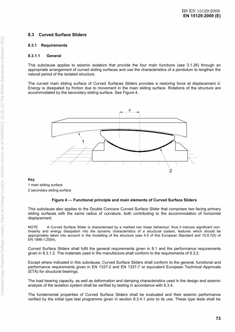
BS EN 15129:2009EN 15129:2009 (E)
73
8.3 Curved Surface Sliders
8.3.1 Requirements
8.3.1.1 General
This subclause applies to seismic isolators that provide the four main functions (see 3.1.26) through an appropriate arrangement of curved sliding surfaces and use the characteristics of a pendulum to lengthen the natural period of the isolated structure.
The curved main sliding surface of Curved Surfaces Sliders provides a restoring force at displacement d. Energy is dissipated by friction due to movement in the main sliding surface. Rotations of the structure are accommodated by the secondary sliding surface. See Figure 4.
Key 1 main sliding surface 2 secondary sliding surface
Figure 4 — Functional principle and main elements of Curved Surface Sliders
This subclause also applies to the Double Concave Curved Surface Slider that comprises two facing primary sliding surfaces with the same radius of curvature, both contributing to the accommodation of horizontal displacement.
NOTE A Curved Surface Slider is characterised by a marked non linear behaviour; thus it induces significant non-linearity and energy dissipation into the dynamic characteristics of a structural system, features which should be appropriately taken into account in the modelling of the structure (see 4.5 of this European Standard and 10.9.7(5) of EN 1998-1:2004).
Curved Surface Sliders shall fulfil the general requirements given in 8.1 and the performance requirements given in 8.3.1.2. The materials used in the manufacture shall conform to the requirements of 8.3.2.
Except where indicated in this subclause, Curved Surface Sliders shall conform to the general, functional and performance requirements given in EN 1337-2 and EN 1337-7 or equivalent European Technical Approvals (ETA) for structural bearings.
The load bearing capacity, as well as deformation and damping characteristics used in the design and seismic analysis of the isolation system shall be verified by testing in accordance with 8.3.4.
The fundamental properties of Curved Surface Sliders shall be evaluated and their seismic performance verified by the initial type test programme given in section 8.3.4.1 prior to its use. These type tests shall be
Lice
nsed
cop
y: Im
peria
l Col
lege
Lon
don,
Impe
rial C
olle
ge L
ondo
n, V
ersi
on c
orre
ct a
s of
24/
09/2
012
15:1
6, (
c) T
he B
ritis
h S
tand
ards
Inst
itutio
n 20
12
BS EN 15129:2009EN 15129:2009 (E)
74
performed separately on a minimum of two (2) full-size specimens of each type equal to that used in the design.
The upper and lower bound values of the design properties referred to in 4.4.2 shall be determined from the type tests and the following variations:
production variability ± 20 %;
temperature and service life changes reported at TU and TL (see 8.3.1.2.5 and 8.3.1.2.6);
ageing change reported in test (see 8.3.1.2.6).
In combining the three a factor of 0,7 shall be used.
The ratio between the upper and lower bound design property value shall be less than 1,8.
8.3.1.2 Performance requirements for Curved Surface Sliders
8.3.1.2.1 General
The performance requirements define quantifiable characteristics that shall be determined for curved surface sliders by type tests. All required limiting values are indicated. Tests that shall be also used as factory production control tests are listed in 8.3.4.2.
When the task of the Curved Surface Sliders is that of only providing three functions, i.e. vertical loads transmission, lateral flexibility and restoring force, and not the dissipation of energy, materials, design requirements and testing procedures shall be fully in accordance with EN 1337-2 or equivalent ETAs for structural bearings. In this case, the sliding isolation tests of Table 15 other than test run S and P1 shall not be carried out.
8.3.1.2.2 Load bearing capacity
Curved Surface Sliders with no lateral displacement present shall be capable of supporting a vertical load equal to 2NSd, where NSd is the dead load plus combination of non-seismic live load(s) according to EN 1990:2002, A.1 (for buildings) or A.2 (for bridges).
The device shall not show any damage and the sliding material of both primary and secondary sliding surface shall not show any sign of progressive flow or deterioration due to inadequate mechanical resistance, bonding and/or confinement in tests in accordance with 8.3.4.1.2.
The load bearing capacity of the Curved Surface Slider shall remain unaltered after the tests specified in 8.3.4.1.5.
NOTE The sliding material of the primary sliding surface acts as conventional bearing material under service conditions and thus it is essential to verify the stability of its mechanical properties after a major earthquake.
8.3.1.2.3 Horizontal displacement capacity
The Isolators shall be capable of accommodating a horizontal displacement equal to γbdEd, where γb is a partial factor for curved surface sliders. The value of γb shall be 1,0.
The isolators shall not include any mechanical elements that serve as end stops, such as containment rings, to avoid the possibility of any impact between rigid mechanical elements causing damage to the device in the event displacements larger than γbdEd take place.
Lice
nsed
cop
y: Im
peria
l Col
lege
Lon
don,
Impe
rial C
olle
ge L
ondo
n, V
ersi
on c
orre
ct a
s of
24/
09/2
012
15:1
6, (
c) T
he B
ritis
h S
tand
ards
Inst
itutio
n 20
12

BS EN 15129:2009EN 15129:2009 (E)
75
8.3.1.2.4 Rotation capacity
NOTE In the Curved Surface Slider, translation movements induce rotational movements in the slider, which are accommodated by the Secondary Sliding Surface.
The Secondary Sliding Surface shall be capable of accommodating the rotation of the slider consequent to a horizontal displacement equal to γbdEd. In accordance with 5.4 of EN 1337-1:2000 this design movement shall be increased by ± 0,005 rad or ± 10 mm/R2 rad - whichever is greater - where R2 mm is the radius of curvature of the Secondary Sliding Surface. This addition only applies for the design of rotation capacity. It shall not be used to calculate stresses.
8.3.1.2.5 Maximum frictional resistance to service movements
NOTE 1 Static friction resistance is the maximum force to produce macroscopic motion occurring during the first movement (see 3.2.3 of EN 1337-2:2004) and is considered in the design of the isolator, its anchoring system and the adjacent structural members.
During the movements developed under service conditions, the Isolators shall develop a frictional force less than or equal to the value specified by the Structural Engineer.
Friction shall not be used to relieve the effects of externally applied horizontal loads other than earthquake induced (see also 6.7 of EN 1337-2:2004).
NOTE 2 The isolators may incorporate restraint devices that eliminate wind or other external loads induced motions in one or all directions and that release the device for full motion in case of earthquake (see 5.2 Fuse Restraints).
The value of the frictional resistance force shall be checked by tests in accordance with 8.3.4.1.3. The measured breakaway frictional force developed by the isolator shall be less than the value specified by the Structural Engineer.
A sliding material specimen shall be subjected to a long-term friction test in accordance with 8.3.4.1.4. The total slide path st shall be declared by the manufacturer and shall not be less than 10 000 m for bridges and 1 000 m for buildings or an equivalent type of structure. The maximum coefficient of friction for each temperature and contact pressure as determined from the long-term friction tests shall be reported, and used to define the design values of the maximum frictional resistance force (see 8.3.3.4.1).
8.3.1.2.6 Isolation characteristics
NOTE 1 Dynamic friction is the mechanism through which energy dissipation is achieved by the Curved Surface Slider. Therefore, this parameter is of crucial importance in determining the response of the seismic isolation system.
Tests in accordance with 8.3.4.1.5 shall be carried out.
Test O therein shall be requested only if the austenitic steel sheet is manufactured with seams. Three cycles shall be completed as specified in Table 15, in a direction of motion perpendicular to the seams.
The force-displacement plots for all tests specified in Table 15 shall have a positive incremental lateral stiffness.
The austenitic steel mating spherical sheet shall not show signs of buckling, permanent deformation or dislocation.
The following requirements for tests specified in Table 15 shall be met:
Test S – Service Conditions:
The maximum recorded horizontal force shall not exceed the value specified by the Structural Engineer.
Tests D1, D2, D3 – Dynamic Conditions:
Lice
nsed
cop
y: Im
peria
l Col
lege
Lon
don,
Impe
rial C
olle
ge L
ondo
n, V
ersi
on c
orre
ct a
s of
24/
09/2
012
15:1
6, (
c) T
he B
ritis
h S
tand
ards
Inst
itutio
n 20
12

BS EN 15129:2009EN 15129:2009 (E)
76
1) There is no more than +/- 10 % change in the restoring stiffness between successive cycles;
2) For each cycle, the restoring stiffness of the upper portion of the cycle is within 5 % of the value obtained for the lower portion;
3) The average of the restoring stiffness for the three cycles is within +/- 15 % of the design value;
4) The maximum lateral force for each of the three cycles is within +/- 15 % of the design value;
5) The energy dissipated per cycle (EDC) for each cycle is no less than 85 % of the design EDC, adjusted for maximum target displacements;
6) The restoring stiffness of each cycle and the average restoring stiffness of one specimen is within +/-15 % of the same stiffness of the other specimen.
Test O – Integrity of overlay:
The requirements of test D3 shall apply. In addition, the test specimen shall be free of cracks and any sign of damage.
Test E – Seismic Condition:
The same acceptance criteria indicated for Dynamic Conditions tests shall apply.
Test B – Bi-directional:
No sign of buckling, permanent deformation or dislocation of the austenitic steel surface shall occur.
Test P1 – Benchmark for factory production control test
Test P2 – Property Verification:
The requirement for the Service Conditions test shall apply.
Test P3 – Benchmark for ageing influence
The change of friction compared to the result of test P1 shall be considered in the design.
Under all loading conditions, the movement in the sliding surfaces shall be smooth and without producing any type of vibrations such as those induced by the stick-slip phenomenon.
The fluctuation of the horizontal force shall be within a range of +/- 5 % of the average restoring force, at any level of bearing displacement. The average restoring force shall be obtained from the best-fit straight line determined by the least square interpolation of the response between +/- 95 % of the peak displacement.
NOTE 2 The magnitude of the force fluctuation due to stick-slip will depend on the compliance of the testing-machine and connections to the device.
The coefficient of friction and all the related performance parameters shall fall within the limits specified by the Structural Engineer under the testing conditions specified in 8.3.4.1.5.
The temperature, ageing and service life dependent upper and lower bound design values referred to in 4.4.2 shall be based on the results of the long-term friction tests as per 8.3.4.1.4. It shall be assumed, that the ratio between this values is equal to the ratio between the dynamic friction values µdyn,max and µdyn,min at the end of phase B taking into account the upper and lower bound service temperatures, TU and TL respectively, determined on the basis of quasi-permanent values as defined in EN 1991-1-5 (see 4.4.2). The influence of ageing on the coefficient of friction shall be taken from the ageing test result as per 8.3.4.1.6. Li
cens
ed c
opy:
Impe
rial C
olle
ge L
ondo
n, Im
peria
l Col
lege
Lon
don,
Ver
sion
cor
rect
as
of 2
4/09
/201
2 15
:16,
(c)
The
Brit
ish
Sta
ndar
ds In
stitu
tion
2012

BS EN 15129:2009EN 15129:2009 (E)
77
NOTE 3 Service life dependence is understood as the change in long-term friction behaviour due to the accumulated sliding under service conditions.
8.3.1.2.7 Wear resistance
NOTE 1 The sliding elements are the critical components of the Curved Surface Sliders and their survival after a major earthquake avoids the need for immediate maintenance interventions or, more seriously, a rehabilitation intervention.
NOTE 2 The object of this verification is to show the isolator’s capacity to survive protracted actions during its service lifespan, as well as the occurrence of a seismic attack.
NOTE 3 Creep deformation is significant and its effect is subtracted from the observed thickness reduction in order to evaluate the extent of the wear correctly. In the absence of more precise measurements, the change in thickness of the sliding material layer after 48 h of constant loading without sliding movement can be taken as the creep deformation correction to be applied.
The wear of the sliding surfaces during their service life and at the occurrence of a design-level earthquake, shall be limited in such a way that an adequate safety margin for the correct functioning of the isolator in accordance with the tests given in 8.3.4.1.4 and 8.3.4.1.5. The following requirements shall be met:
a) the reduction in thickness of the bearing sliding material, measured as the difference between the sliding material thickness at each of the eight (8) symmetrically placed locations prior to and following the prototype bearing testing and corrected for the effect of creep during the tests, shall not exceed 20 % of the initial thickness;
b) the depth of any scratch produced by scoring of the austenitic steel surface shall be less than 0,05 mm;
c) the deformation of the backing plates shall be such that the maximum deviation ∆z from theoretical curved surface within the area of the mating sliding sheet shall not exceed 0,0003 × L or 0,2 mm, whichever is greater. L is the diameter of the circumscribing circle of single or multiple sliding material sheets (see Figures 3, 4 and 5 in EN 1337-2:2004 for clarification of the definition).
8.3.2 Materials
8.3.2.1 Sliding material
Only materials suitable for curved surfaces of structural sliding bearings as per EN 1337-2 or equivalent ETAs shall be used.
NOTE For primary sliding surfaces, un-dimpled sheets without lubrication may be used.
8.3.2.2 Mating surfaces
Austenitic steel in accordance with EN 10088-2, 1.4401 + 2B or 1.4404 +2B or backing plates with at least 100 µm hard chromium plating according to EN ISO 6158 shall be used as mating surface. The thickness of austenitic steel sheets shall be at least 2,5 mm.
The surface characteristics of the primary sliding surface shall be defined by the manufacturer and considered in the sliding behaviour tests as per 8.3.4.1.4 and 8.3.4.1.5. If the primary sliding surface has the function to provide energy dissipation as well as isolation, the requirements for its surface characteristics, that is roughness Rz in accordance with EN ISO 4287 and hardness according to EN ISO 6507-2, shall be declared by the manufacturer.
The surface characteristics of the secondary sliding surface and primary sliding surface not required to provide energy dissipation shall be in accordance with subclauses 5.4 and 5.5 of EN 1337-2:2004.
Type tests, and factory production control tests on each batch of material shall be performed to verify that the requirements are met.
Lice
nsed
cop
y: Im
peria
l Col
lege
Lon
don,
Impe
rial C
olle
ge L
ondo
n, V
ersi
on c
orre
ct a
s of
24/
09/2
012
15:1
6, (
c) T
he B
ritis
h S
tand
ards
Inst
itutio
n 20
12

BS EN 15129:2009EN 15129:2009 (E)
78
8.3.2.3 Lubricants
If the sliding surface is lubricated, the lubricant shall be in accordance with subclause 5.8 of EN 1337-2:2004.
8.3.2.4 Backing plates
Steel plates in accordance with EN 10025, cast iron in accordance with ISO 1083, cast carbon steel in accordance with ISO 3755 or stainless steel in accordance with EN 10088 shall be used for the backing plates, as appropriate.
The substrate for hard chromium plated sliding surfaces shall be steel grade S 355 J2G3 or fine grain steel of the same or higher grade in accordance with EN 10025 series.
8.3.3 Design
8.3.3.1 Load bearing capacity
The load bearing capacity shall be verified in accordance with 6.3.1 and 6.3.3 of EN 1337-7:2004.
For spherical sliding surfaces with an included angle 2θ ≤ 60°, the method of stress verification shall be in accordance with the method given in EN 1337-7. For spherical sliding surfaces with an included angle 2θ > 60°, compressive stress verification shall be conducted using appropriate calculation methods, such as Finite Elements Modelling.
NOTE A valid simplified method for calculating stress distribution in spherical bearing surfaces within the linear-elastic range is shown in Annex I.
8.3.3.2 Horizontal displacement capacity
The mating surface dimensions of the primary sliding surface shall be so proportioned that in all conditions they completely cover the primary bearing sliding material.
8.3.3.3 Rotation capacity
The mating surface dimensions of the secondary sliding surface shall be so proportioned that in all conditions they completely cover the secondary bearing sliding material.
8.3.3.4 Friction resistance
NOTE During movements of Curved Surface Sliders, friction develops in both the primary and secondary sliding surface. Notwithstanding, the requirements for the two surfaces are different, inasmuch as friction in the primary sliding surface serves to dissipate energy, whilst in the secondary sliding surface friction needs to be minimized to ensure proper distribution of pressure in the bearing’s sliding materials.
8.3.3.4.1 Maximum frictional resistance force
The static coefficient of friction µmax shall be used for verification of the isolator and the structure in which it is incorporated. The design value of the maximum frictional resistance force is given by the following equation:
)(max, bSddxy dsignNF &µ= (26)
where
NSd is the normal force on the device under non-seismic design conditions
sign )( bd& is the sign of the velocity vector )( bd& , and
Lice
nsed
cop
y: Im
peria
l Col
lege
Lon
don,
Impe
rial C
olle
ge L
ondo
n, V
ersi
on c
orre
ct a
s of
24/
09/2
012
15:1
6, (
c) T
he B
ritis
h S
tand
ards
Inst
itutio
n 20
12

BS EN 15129:2009EN 15129:2009 (E)
79
db is the relative displacement of the two sliding surfaces
a) primary sliding surface
The values of static coefficient of friction µmax are obtained from long-term friction tests as per 8.3.4.1.4. The design values for different pressure levels are the maximum values measured in the phases A, C and D at the end of the test at various pressures. Intermediate values shall be obtained by linear interpolation or through Equation (29).
For pressures below 0,08 fk or above 0,33 fk, where fk is the characteristic compressive strength of the sliding material (see EN 1337-2:2004, Table 10), the coefficient of friction shall be assumed equal to the threshold values.
The design temperature TL is the frequently occurring low temperature as defined in EN 1990:2002,1.5.1.3.17 and shall be specified by the Structural Engineer. In the absence of more precise values, TL = -10°C for bridges and 0°C for buildings shall be used.
b) secondary sliding surface
When lubricated PTFE is used as sliding material, its coefficient of friction shall comply with subclause 4.1 of EN 1337-2:2004. The friction coefficient of sliding materials not complying with that subclause shall comply with the values specified in the ETA permitting their use in structural devices.
8.3.3.4.2 Sliding Isolation
NOTE The behaviour of the isolator during a seismic attack is governed by the frictional and geometrical characteristics of the primary sliding surface. See also EN 1337-7:2004, A.2.1.
The upper and lower bound values of the dynamic coefficient of friction shall be used for the design and verification of the isolator as well as the dynamic analysis of the structure.
8.3.3.5 Backing plates
Backing plates shall be designed and verified in accordance to subclause 6.9 of EN 1337-2:2004 adapting Equation (6) to the used sliding material.
They shall be made out of solid elements, without lightening hollows and ribs.
8.3.3.6 Separation of sliding surfaces
NOTE 1 Separation of the sliding surfaces may lead to wear due to contamination and increased deformation of the bearing sliding material secondary to faulty confinement of the latter. As this could jeopardize long-term fitness for use, the condition σp = 0 (where σp is the contact pressure) is considered as the serviceability limit state.
It shall be verified that σp ≥ 0 under all load combinations at serviceability limit state. For the verification, the sliding material shall be assumed to be linear elastic and the backing plates deemed to be rigid.
For spherical sliding surfaces with an included angle 2θ ≤ 60°, the condition σp ≥ 0 is satisfied at the serviceability limit state when the total eccentricity et satisfies the relation:
8Let ≤ (27)
where L is the diameter of the projected area.
NOTE 2 The method for calculating the eccentricities in spherical surfaces is given in Annex A of EN 1337-7:2004. Lice
nsed
cop
y: Im
peria
l Col
lege
Lon
don,
Impe
rial C
olle
ge L
ondo
n, V
ersi
on c
orre
ct a
s of
24/
09/2
012
15:1
6, (
c) T
he B
ritis
h S
tand
ards
Inst
itutio
n 20
12
BS EN 15129:2009EN 15129:2009 (E)
80
For spherical sliding surfaces with an included angle 2θ > 60°, the verification of the condition σp ≥ 0 shall be conducted using suitable calculation methods such as the simplified method shown in Annex I or Finite Element Modelling.
8.3.4 Testing
8.3.4.1 Type Testing
8.3.4.1.1 General
Tests shall be carried out on the Curved Surface Slider and samples of sliding elements to demonstrate the satisfaction of the general performance characteristics specified in 8.3.1.2.
NOTE 1 The test programme involves a substantial total energy input to the Curved Surface Slider. Therefore, care is required in the execution of the test programme to ensure that any tests performed in quick succession will not excessively overheat the isolator. To hold the latter in check, the temperature at the centre of the primary bearing sliding material needs to be monitored and reported. It is advisable to divide the test programme into groups of tests. After performing one group, the isolator is allowed to cool to a temperature specified by the manufacturer before performing the subsequent test group.
NOTE 2 The tests listed in this subclause may be performed in an order different from that presented.
The tests shall be arranged into groups in accordance with the criterion that the total energy input to the Curved Surface Slider in each group of tests does not exceed 1,5 times the energy dissipated by the isolator during a design level earthquake.
If entrance and exit cycles are required for the correct execution of the test, the related energy input shall be taken into account.
The tests shall be performed at a temperature of (23 ± 5) °C, unless some other temperature is specified in 8.3.4 or by the Structural Engineer.
Experimental results obtained from tests on similar bearings (reference devices) that satisfy all the requirements of this clause may be used for new devices provided:
1) design displacement of the new device is within ± 20 % of the reference design value;
2) bearing capacity of the new device is within ± 20 % of the reference design value;
3) design coefficients of friction are identical for new and reference device;
4) basic materials for sliding elements are identical for new and reference device;
5) the radius of curvature of both primary and secondary curved surfaces is within ± 20 % the reference design value:
Prior to performing these tests, the isolator shall be subjected to a 10-minute pre-loading with an axial load equal to the non-seismic design load NSd. At the end of the pre-loading time, the thickness of the sliding material shall be measured at eight (8) symmetrically spaced locations in both the primary and secondary sliding element by using a thickness gauge accurate to 0,05 mm. This set of values shall represent the benchmark values for further verifications.
NOTE 1 For safety reasons the thickness measurement may be carried out by electronic sensors or replaced by measurements on unloaded devices, if appropriate conversion rules for the loaded condition are available.
NOTE 2 If the sliding material is recessed in its backing plate, “sliding material thickness” is the protrusion of the sliding material sheet from its recess. Li
cens
ed c
opy:
Impe
rial C
olle
ge L
ondo
n, Im
peria
l Col
lege
Lon
don,
Ver
sion
cor
rect
as
of 2
4/09
/201
2 15
:16,
(c)
The
Brit
ish
Sta
ndar
ds In
stitu
tion
2012

BS EN 15129:2009EN 15129:2009 (E)
81
8.3.4.1.2 Load bearing capacity
NOTE The object of this test is to verify the overload capacity of Curved Surface Sliders.
The loading history of the test shall be the following: at zero displacement, apply a load equal to 2NSd (see 8.3.1.2.2) and maintain it constant for 1 min. A continuous plot of the vertical force vs. displacement shall be recorded.
8.3.4.1.3 Frictional resistance force under service conditions
NOTE The object of these tests is to verify the maximum lateral force developed by the isolator under service conditions.
Loading history: At zero displacement, apply a vertical load equal to the non-seismic design load NSd and keep it constant for 30 min, then impose a sliding velocity v ≤ 0,1 mm/s for 1 min. A continuous plot of the horizontal force vs. displacement shall be recorded.
8.3.4.1.4 Static coefficient of friction
NOTE 1 This subclause describes the method for determining the static coefficient of friction of material samples, as well as the wear resistance of the primary curved sliding surface where no lubricant is used. The principles of verification, the terms and definitions as well as the test equipment and specimens are given in Annex D of EN 1337-2:2004.
A long-term friction test with the programme in accordance with Table 13 shall be carried out under the following conditions:
Table 13 – Long-term friction test programme
Phase Number 1 2 3 4 5
Type A B A C D
Distance 22 m st 22 m 22 m 22 m
Specimen: Mating surface and sliding material according to EN 1337-2:2004 or equivalent ETA
Diameter of sliding material specimen L = 75 mm
In the phases A, C and D the static coefficients of friction shall be measured at the different temperature levels indicated in Table 14 and Figure 5.
Lice
nsed
cop
y: Im
peria
l Col
lege
Lon
don,
Impe
rial C
olle
ge L
ondo
n, V
ersi
on c
orre
ct a
s of
24/
09/2
012
15:1
6, (
c) T
he B
ritis
h S
tand
ards
Inst
itutio
n 20
12
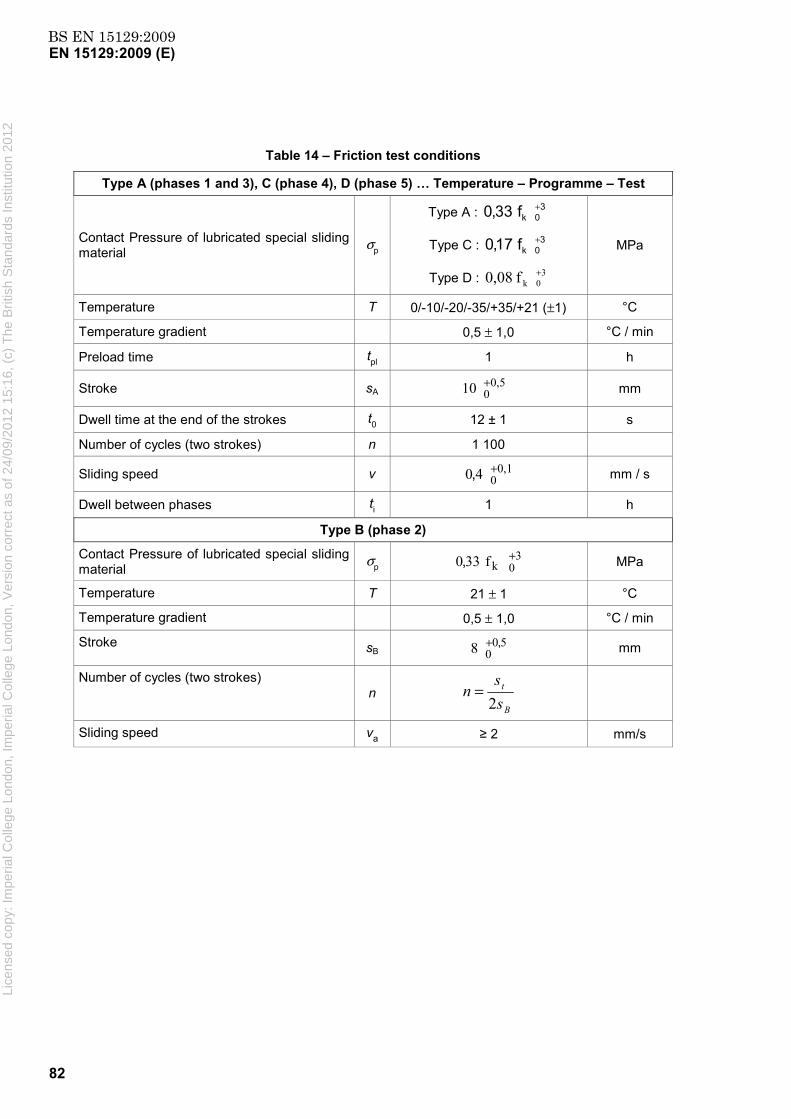
BS EN 15129:2009EN 15129:2009 (E)
82
Table 14 – Friction test conditions
Type A (phases 1 and 3), C (phase 4), D (phase 5) … Temperature – Programme – Test
Contact Pressure of lubricated special sliding material σp
Type A : 30kf33,0 +
Type C : 30kf17,0 +
Type D : 30kf08,0 +
MPa
Temperature T 0/-10/-20/-35/+35/+21 (±1) °C
Temperature gradient 0,5 ± 1,0 °C / min
Preload time tpl 1 h
Stroke sA 0,5
010 + mm
Dwell time at the end of the strokes t0 12 ± 1 s
Number of cycles (two strokes) n 1 100
Sliding speed v 0,1040 +, mm / s
Dwell between phases ti 1 h
Type B (phase 2)
Contact Pressure of lubricated special sliding material σp
30kf330 +, MPa
Temperature T 21 ± 1 °C
Temperature gradient 0,5 ± 1,0 °C / min
Stroke sB 5008 ,+ mm
Number of cycles (two strokes) n
B
t
ss
n2
=
Sliding speed va ≥ 2 mm/s
Lice
nsed
cop
y: Im
peria
l Col
lege
Lon
don,
Impe
rial C
olle
ge L
ondo
n, V
ersi
on c
orre
ct a
s of
24/
09/2
012
15:1
6, (
c) T
he B
ritis
h S
tand
ards
Inst
itutio
n 20
12

BS EN 15129:2009EN 15129:2009 (E)
83
Figure 5 — Temperature profile of the long-term sliding test
If the minimum temperature, Tmin, for the intended use is extended to – 50 °C the temperature range in the Temperature Programme Test shall be extended as shown in Figure 6. If the minimum temperature, Tmin, for the intended use is higher than the temperature of some sections of the Temperature Programme Test, during those sections the temperature shall be kept constant and equal to Tmin.
NOTE 2 Tmin is the lowest likely service temperature and is not identical to TL.
Lice
nsed
cop
y: Im
peria
l Col
lege
Lon
don,
Impe
rial C
olle
ge L
ondo
n, V
ersi
on c
orre
ct a
s of
24/
09/2
012
15:1
6, (
c) T
he B
ritis
h S
tand
ards
Inst
itutio
n 20
12

BS EN 15129:2009EN 15129:2009 (E)
84
Figure 6 — Example of Temperature programme of the long-term sliding test for Tmin = – 50 °C and Tmin = – 20 °C
8.3.4.1.5 Sliding isolation tests
NOTE 1 The object of these tests is to verify the dynamic behaviour of Curved Surface Sliders in terms of frictional resistance (or coefficient of friction), the damping capacity, as well as stability under repeated cycling.
The sliding isolation tests shall be conducted in accordance with the test matrix provided in Table 15.
NOTE 2 For sliding materials used in the bearing, the relationship between the friction coefficient µ and the pressure σp is given by the expression:
)( pf σµ = (28)
As an example for thermoplastic materials the following expression may be used
p
Cσ
=µ (29)
where C is a constant.
This function depends on the type of sliding material used, roughness of mating surfaces, temperature, velocity etc. The Structural Engineer should take into account the latter when specifying the values for the coefficient of friction under different loading conditions.
A continuous plot of the horizontal force-displacement hysteresis loop shall be recorded for each run.
The displacement input waveform shall be sinusoidal of the type d(t) = dx⋅ sin (2π⋅ fo⋅t).
Frequency fo [Hz] shall be properly chosen in relation to stroke dx [mm] so as – for each type of test – the peak velocity vo = 2π⋅fo·dx [mm/s] equals the specified value vEd.
The dynamic coefficient of friction µdyn shall be evaluated as follows:
(a) when measured for the first cycle: Lice
nsed
cop
y: Im
peria
l Col
lege
Lon
don,
Impe
rial C
olle
ge L
ondo
n, V
ersi
on c
orre
ct a
s of
24/
09/2
012
15:1
6, (
c) T
he B
ritis
h S
tand
ards
Inst
itutio
n 20
12

BS EN 15129:2009EN 15129:2009 (E)
85
XS
hdyn dN
A⋅⋅
=µ4
1,1, (30)
(b) when computed for the 3 cycles:
∑= ⋅⋅
⋅=µ3
1
,3, 43
1i XS
ihdyn dN
A (31)
where
Ah,i is the area enclosed within the hysteresis loop in the i- cycle [kJ];
Ns is the value of vertical axial load under which the isolator is to be tested [kN];
dx is the value of the peak horizontal displacement achieved during the test [m].
Table 15 — Test Matrix to verify the sliding isolation behaviour
Type of Test Test
run
Compression
Load NS [kN]
Displacement
dX [m]
Peak velocity
vo [mm/s]
Number of
complete cycles
Service S NSd maximum non
seismic movement
5 20
Benchmark
P1 NSd 1,0· dbd 50 3
Dynamic 1 D1 NSd 0,25· dbd vEd 3
Dynamic 2 D2 0,5· dbd vEd 3
Dynamic 3 D3 1,0· dbd vEd 3
Integrity of overlay O NSd 1,0· dbd vEd 3
Seismic
E NEd,max and
NEd,min dbd vEd 3
Bi-directional B NSd 1,0· dbd vEd 3
Property verification P2 NSd 1,0· dbd vEd 3
Ageing P3 NSd 1,0· dbd 50 3
Test B shall be performed with the simultaneous application of a sinusoidal displacement input waveform in two perpendicular directions.
NOTE 3 The equation to obtain a “clover leaf” path is the following:
(x² + y²)³ = x² * y² (32)
Lice
nsed
cop
y: Im
peria
l Col
lege
Lon
don,
Impe
rial C
olle
ge L
ondo
n, V
ersi
on c
orre
ct a
s of
24/
09/2
012
15:1
6, (
c) T
he B
ritis
h S
tand
ards
Inst
itutio
n 20
12

BS EN 15129:2009EN 15129:2009 (E)
86
If testing equipment is unable to perform test B, the test can be completed after a rotation of 90º of the bearing in order to involve a displacement path perpendicular to the one verified with previous tests.
Restoring stiffness shall be measured from the best-fit straight line determined by the “least-squares” method the central 95 % of the cycle displacement range, see F.4.1.
One value shall be obtained for the upper and the lower portion of the force-displacement curve respectively.
The average of the two measurements shall also be calculated.
NOTE 4 Unless otherwise specified, restoring stiffness for one cycle is intended to be the average between upper and lower stiffness.
At the end of the test programme shown in Table 15 the sliding material thickness shall be measured in the presence of an axial force equal to the permanent load NSd by using a thickness gauge accurate to 0,05 mm at the same 8 symmetrically spaced locations used for assessing the benchmark values (see 8.3.4.1.1).
Subsequently, the isolator shall be disassembled for visual and instrumental examination.
8.3.4.1.6 Ageing test
NOTE The object of these test is to verify the influence of ageing of the sliding material in terms of frictional resistance by an accelerated ageing test.
The ageing test shall be conducted on a Curved Surface Slider with a sample of sliding elements previously tested in accordance with the conditions of type P1 of Table 15 to determine the change of the dynamic coefficient of friction. The test requirements of type P3 in Table 15 apply.
Before test P3, the sliding material shall be exposed for 14 days to a temperature of 70 °C in anaerobic conditions.
After test P3, the dynamic coefficient of friction shall have changed by less than 20 % due to the ageing.
The test result is representative for all sizes of device. The ITT shall not be repeated, if the limitation of the applicability of reference values as per 8.3.4.1.1 is exceeded.
8.3.4.2 Factory production control tests
8.3.4.2.1 Property verification test
One full-size unit per production lot shall be subjected to factory production control tests comprising the following:
a) Vertical load bearing capacity (see 8.3.1.2.2 and 8.3.4.1.2);
b) Frictional resistance force under service conditions (see 8.3.1.2.5 and 8.3.4.1.3);
c) Test run P1 (see 8.3.1.2.6 and 8.3.4.1.5).
For the purpose of the factory production control tests, a production lot shall be a set of no more than 20 identical units. Curved Surface Sliders with different design movements due to non-seismic inputs are considered to be identical for this purpose, if all the other design parameters are equal.
If the load bearing capacity of a unit exceeds 20 % of the overall weight of the supported structure the number of production units subjected to production tests, for that set, shall be doubled.
The same requirement as indicated for Type Testing shall apply. Lice
nsed
cop
y: Im
peria
l Col
lege
Lon
don,
Impe
rial C
olle
ge L
ondo
n, V
ersi
on c
orre
ct a
s of
24/
09/2
012
15:1
6, (
c) T
he B
ritis
h S
tand
ards
Inst
itutio
n 20
12
BS EN 15129:2009EN 15129:2009 (E)
87
8.3.4.2.2 Material testing
The testing of raw materials and constituents shall be carried out in accordance with Table 16 of EN 1337-2:2004 or in the presence of other sliding materials the equivalent regulations in the relevant ETA.
NOTE The respective short-term friction test can be used for the evalution of conformity of non lubricated material in primary sliding surfaces.
8.3.5 Manufacturing, Assembly and Tolerances
NOTE This subclause deals with workmanship, assembly and fitting tolerances.
8.3.5.1 Sliding elements
The sliding materials shall be attached in accordance with EN 1337-2:2004, subclause 7.1.1 or the methods specified in the equivalent ETAs.
The maximum deviation ∆z from theoretical plane or curved surface within the area of the mating sliding sheet shall not exceed 0,0003 × L or 0,2 mm, whichever is greater. Care shall be taken to ensure that the austenitic steel sheet is fully in contact with the backing plate over the area, which will be in contact with the sliding sheet.
8.3.5.2 Lubricating
After cleaning and prior to assembly, the sliding sheet of the secondary sliding surface shall be lubricated with lubricant according to EN 1337-2 in such a way that all the dimples are filled.
For the primary sliding surface any contamination of the sliding material with lubricant shall be prevented.
8.3.5.3 Backing Plates
Surfaces of backing plates in contact with sliding materials or anchor and shimming plates shall be treated in such a way that the maximum deviation ∆z from theoretical curved surface shall not exceed 0,0003 × d or 0,2 mm, whichever is greater, where d is here the length of the diagonal or diameter of the backing plate.
8.3.5.4 Assembly
All devices shall be assembled at the supplier’s factory. Suitable, temporary assembly ties shall be provided, so that the entire assembly is dispatched, in protective packaging, as a unit and remains intact when uncrated and installed. Packaging shall be suitable to prevent damage from impact as well as from dust and moisture contamination during transportation and storage. All devices shall be delivered ready for installation and appropriately marked with their identification codes a specified in the Specification document. The devices are marked by the designation plate and in addition on the upper surface for clear identification of the installation location and its orientation. No disassembly on site shall occur without assistance of the manufacturer.
8.3.5.5 Protection against contamination and corrosion
NOTE General requirements for corrosion protection are given in EN 1337-9. This subclause gives additional requirements for sliding elements.
Where the austenitic steel sheet is attached by full area bonding or by continuous fillet weld, provided the area covered by the austenitic steel sheet is free from rust and rust inducing contaminants, no further treatment of the backing plate behind the austenitic steel sheet is required.
A positive means shall be provided to avoid any possible moisture contamination in case of cracked weld fillets. Li
cens
ed c
opy:
Impe
rial C
olle
ge L
ondo
n, Im
peria
l Col
lege
Lon
don,
Ver
sion
cor
rect
as
of 2
4/09
/201
2 15
:16,
(c)
The
Brit
ish
Sta
ndar
ds In
stitu
tion
2012

BS EN 15129:2009EN 15129:2009 (E)
88
The areas of the backing plate behind the sliding material and austenitic steel sheets attached by confinement, screwing, counterpunched screwing or riveting shall be protected by one coat of primer (dry film thickness 20 µm to 100 µm).
Provision against contamination of the sliding surface shall be made by suitable devices. Such protection devices shall be easily removable for the purpose of inspection. Since hard chromium plating is not resistant to chlorides in acid solution or to fluorides and can be damaged by air borne particles, such that occur in industrial environments, special provision shall be made to protect the surfaces in these conditions.
Prior to assembly, the sliding surfaces shall be cleaned.
During assembly process, provisions shall be taken against contamination of sliding surfaces.
8.3.5.6 Reference surface for installation
In order to ensure bearing alignment in accordance with EN 1337-11, a reference surface or other suitable device shall be installed on the sliding element. The deviation from parallel of the reference surface with respect to the plane projection of the primary sliding surface shall not exceed 0,001 rad.
The installation of the device shall be executed in accordance with EN 1337-11.
8.4 Flat Surface Sliders
8.4.1 Requirements
The sliding elements of Flat Surface Sliders shall conform to EN 1337-2 or be covered by an ETA.
The sliding elements shall be combined with a rotating element in accordance with EN 1337-1.
NOTE 1 Flat Surface Sliders can be considered as the limiting case for Curved Surface Sliders with the radius of curvature, ∞=R .
When Flat Surface Sliders are used to dissipate energy, in addition to transmit vertical loads and provide lateral flexibility, their sliding elements shall conform to 8.3.1 of this European Standard.
NOTE 2 In Curved Surface Sliders restoring force is provided by gravity due to their geometry, while sliding devices with flat sliding surface do not possess any re-centring capability.
Flat Surface Sliders shall be used in combination with appropriate devices that provide adequate restoring capability to the seismic isolation system.
8.4.2 Materials
Materials shall conform to 8.3.2 of this European Standard.
8.4.3 Design
Design shall conform to 8.3.3 of this European Standard.
8.4.4 Testing
Testing shall conform to 8.3.4 of this European Standard.
8.4.5 Manufacturing, Assembly and Tolerances
Manufacturing, Assembly and Tolerances shall conform to 8.3.5 of this European Standard.
Lice
nsed
cop
y: Im
peria
l Col
lege
Lon
don,
Impe
rial C
olle
ge L
ondo
n, V
ersi
on c
orre
ct a
s of
24/
09/2
012
15:1
6, (
c) T
he B
ritis
h S
tand
ards
Inst
itutio
n 20
12
BS EN 15129:2009EN 15129:2009 (E)
89
9 Combinations of Devices
9.1 Requirements
9.1.1 General
Anti-seismic devices comprising a combination of components shall meet the requirements given in Clause 4 except where indicated otherwise in this clause. The connection between the individual components shall allow all relative displacements, translations and rotations, as appropriate.
The upper and lower bound values of the design properties referred to in 4.4.2 shall be determined from type tests and the following variations:
production variability agreed for the factory production control tests;
temperature changes reported at TU and TL;
ageing or time in service (unless it can be demonstrated to the satisfaction of the Structural Engineer that the properties of the components are not significantly affected by chemical ageing or time in service).
NOTE 1 Flat Surface Sliders often form part of a combined device. It may consist of the combination of a structural bearing allowing sliding movement in one or two directions in accordance with the relevant parts of EN 1337 or equivalent ETAs and one or more anti-seismic devices in accordance with the relevant clauses of this European Standard. The anti-seismic devices are connected to the components of the structural bearing so that in case of earthquake the consequent relative displacement will activate them. Most frequently, the structural bearings utilized for that purpose are pot bearings or spherical bearings with sliding elements conforming with EN 1337-5, EN 1337-7 and EN 1337-2 or equivalent ETAs, combined with rigid connection devices, linear devices, non linear devices, viscous dampers or elastomeric isolators conforming with the relevant clauses of this European Standard. Also a combination with more than one type of anti-seismic device is possible.
NOTE 2 For the combination of a bearing and rigid connection device see Clause 5.
9.1.2 Particular requirements
The combined devices shall meet the performance requirements specified by the Structural Engineer. The capability of the combined device to meet those requirements shall be verified by tests carried out according to 9.4. The components of the combined device shall meet the requirements of the appropriate parts of EN 1337, equivalent ETAs or the relevant clause of this European Standard.
For devices combined with one or more sacrificial restraints, the performance requirements shall cover the ability of the device to function properly under non-seismic service load conditions without interference from the restraints, and the necessity for all restraints to fail at the intended load or displacement condition.
9.2 Materials
The materials used in the manufacture of the combined device shall meet the requirements given in the appropriate parts of EN 1337, equivalent ETAs or the relevant clauses of this European Standard for the individual components.
9.3 Design
The individual components of the combined device shall be designed according to the rules given in the appropriate parts of EN 1337, equivalent ETAs or the relevant clauses of this European Standard.
In determining the loads and displacements imposed on the individual components, account shall be taken of any interactive effects between the components. Li
cens
ed c
opy:
Impe
rial C
olle
ge L
ondo
n, Im
peria
l Col
lege
Lon
don,
Ver
sion
cor
rect
as
of 2
4/09
/201
2 15
:16,
(c)
The
Brit
ish
Sta
ndar
ds In
stitu
tion
2012
BS EN 15129:2009EN 15129:2009 (E)
90
The connections between the movable and fixed components of the device shall allow all relative movements foreseen amplified by the reliability factor γx, and shall be designed to transmit the design forces corresponding to the displacements amplified by the same factor γx. The minimum value of γx shall be that appropriate to the component requiring the highest value.
9.4 Testing
9.4.1 General
The tests shall be performed at a temperature of (23 ± 5) oC, unless the test is to establish the effect of varying the temperature.
The tests shall be performed at full-scale, unless, with the agreement of the Structural Engineer, this is deemed impractical. If full-scale type tests of the complete device are not performed, tests of each component at full-scale shall be carried out. The individual components of the combined device shall be tested according to the rules given in the appropriate parts of EN 1337, equivalent ETAs or the relevant clauses of this European Standard.
9.4.2 Type Testing
Type tests for each design of combined device shall be carried out to demonstrate that the requirements specified in 9.1.2 are satisfied, and, where appropriate, to establish the upper and lower bound values of the design properties. Tests to establish the displacement or load capacity of the device shall use fixings of the same design as those to be used in fixing the device to the protected structure and manufactured from similar materials.
The type tests may be performed on a single device.
Type tests on the complete device shall be such that they validate and characterise the properties of each component of the device to the same extent as the type tests required for each component as given in the appropriate parts of EN 1337, equivalent ETAs or the relevant clauses of this European Standard. The tests shall also verify that there is no unintended interference between the components of the combined device affecting their performance under both non-seismic and seismic actions.
Type tests performed on individual components of the device shall conform to the appropriate parts of EN 1337, equivalent ETAs or the relevant clauses of this European Standard.
9.4.3 Factory Production Control testing
Factory Production Control tests shall be performed either on a complete device or on the individual components.
Factory Production Control tests on the complete device shall be such that they are in accordance with the Factory Production Control tests of each component of the device. Factory Production Control tests on individual components of the device shall conform to the appropriate parts of EN 1337, equivalent ETAs or the relevant clauses of this European Standard.
10 Evaluation of conformity
10.1 General
The conformity of the anti-seismic device with the requirements of this standard and with the stated values shall be demonstrated by:
Initial Type Testing;
Lice
nsed
cop
y: Im
peria
l Col
lege
Lon
don,
Impe
rial C
olle
ge L
ondo
n, V
ersi
on c
orre
ct a
s of
24/
09/2
012
15:1
6, (
c) T
he B
ritis
h S
tand
ards
Inst
itutio
n 20
12
BS EN 15129:2009EN 15129:2009 (E)
91
factory production control by the manufacturer, including product assessment.
The given system of evaluation of conformity is also valid for non-series production.
10.2 Type testing
10.2.1 Initial Type Testing
Initial Type Testing (ITT) shall be performed to show conformity with this European Standard. Tests previously performed in accordance with the provisions of this European Standard [same product, same characteristic(s), test method, sampling procedure, system of attestation of conformity, etc.] may be taken into account. In addition, Initial Type Testing shall be performed at the beginning of the production of a new anti-seismic device or at the beginning of a new method of production (where this may affect the stated properties).
Combined devices are considered to be in conformity with the requirements of this European Standard if the individual devices are themselves CE marked.
All characteristics defined in the relevant clause for the type of device as detailed in Clauses 5 to 9 and according to the Tables 16 to 21 shall be subject to Initial Type Testing.
Certificates containing material properties established in 5.2.2, 5.3.2, 6.3, 6.4.2, 7.2, 8.2.2, 8.2.4.2.2, 8.2.4.3.2, 8.3.2, 9.2 shall be individually examined during the Initial Type Testing and shall be retained by the manufacturer of the anti-seismic device.
Initial Type Testing shall be supplemented with the relevant calculations from design requirement clauses of the individual type of device for the evaluation of the final performance of the anti-seismic device.
For combined devices, the extent of Initial Type Testing shall be such that the control for each type of component within the combined device is equivalent to that specified for the component in the appropriate table in this clause, in the conformity evaluation clause of the appropriate European Standard or in an equivalent ETA. Individual components of the combined device receive CE marking on the basis of the Initial Initial Type Testing of each component. The control and testing of the combined device shall also be in accordance with 9.4.2.
Lice
nsed
cop
y: Im
peria
l Col
lege
Lon
don,
Impe
rial C
olle
ge L
ondo
n, V
ersi
on c
orre
ct a
s of
24/
09/2
012
15:1
6, (
c) T
he B
ritis
h S
tand
ards
Inst
itutio
n 20
12
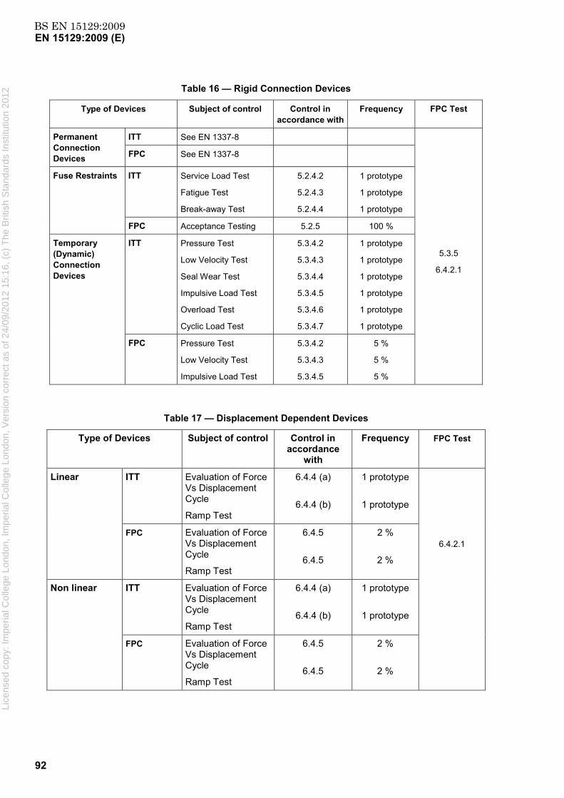
BS EN 15129:2009EN 15129:2009 (E)
92
Table 16 — Rigid Connection Devices
Type of Devices Subject of control Control in accordance with
Frequency FPC Test
Permanent Connection Devices
ITT See EN 1337-8
5.3.5
6.4.2.1
FPC See EN 1337-8
Fuse Restraints ITT Service Load Test
Fatigue Test
Break-away Test
5.2.4.2
5.2.4.3
5.2.4.4
1 prototype
1 prototype
1 prototype
FPC Acceptance Testing 5.2.5 100 %
Temporary (Dynamic) Connection Devices
ITT Pressure Test
Low Velocity Test
Seal Wear Test
Impulsive Load Test
Overload Test
Cyclic Load Test
5.3.4.2
5.3.4.3
5.3.4.4
5.3.4.5
5.3.4.6
5.3.4.7
1 prototype
1 prototype
1 prototype
1 prototype
1 prototype
1 prototype
FPC Pressure Test
Low Velocity Test
Impulsive Load Test
5.3.4.2
5.3.4.3
5.3.4.5
5 %
5 %
5 %
Table 17 — Displacement Dependent Devices
Type of Devices Subject of control Control in accordance
with
Frequency FPC Test
Linear ITT Evaluation of Force Vs Displacement Cycle
Ramp Test
6.4.4 (a)
6.4.4 (b)
1 prototype
1 prototype
6.4.2.1 FPC Evaluation of Force
Vs Displacement Cycle
Ramp Test
6.4.5
6.4.5
2 %
2 %
Non linear ITT Evaluation of Force Vs Displacement Cycle
Ramp Test
6.4.4 (a)
6.4.4 (b)
1 prototype
1 prototype
FPC Evaluation of Force Vs Displacement Cycle
Ramp Test
6.4.5
6.4.5
2 %
2 %
Lice
nsed
cop
y: Im
peria
l Col
lege
Lon
don,
Impe
rial C
olle
ge L
ondo
n, V
ersi
on c
orre
ct a
s of
24/
09/2
012
15:1
6, (
c) T
he B
ritis
h S
tand
ards
Inst
itutio
n 20
12

BS EN 15129:2009EN 15129:2009 (E)
93
Table 18 — Velocity Dependent Devices
Type of Devices Subject of control Control in accordance
with
Frequency
Fluid Viscous Dampers
ITT Pressure Test
Low Velocity Test
Constitutive Law Test
Damping Efficiency Test
Wind Load Cyclic Test
Seal Wear Test
Stroke Verification Test
7.4.2.2
7.4.2.3
7.4.2.5
7.4.2.7
7.4.2.8
7.4.2.9
7.4.2.10
1 prototype
1 prototype
1 prototype
1 prototype
1 prototype
1 prototype
1 prototype
FPC Pressure Test
Low Velocity Test
Constitutive Law Test
Damping Efficiency Test
7.4.2.2
7.4.2.3
7.4.2.5
7.4.2.7
100 %
5 %
5 %
5 %
Fluid Spring Dampers
ITT Pressure Test
Low Velocity Test
Constitutive Law Test
Damping Efficiency Test
Wind Load Cyclic Test
Seal Wear Test
Stroke Verification Test
7.4.2.2
7.4.2.4
7.4.2.6
7.4.2.7
7.4.2.8
7.4.2.9
7.4.2.10
1 prototype
1 prototype
1 prototype
1 prototype
1 prototype
1 prototype
1 prototype
FPC Pressure Test
Low Velocity Test
Constitutive Law Test
Damping Efficiency Test
7.4.2.2
7.4.2.4
7.4.2.6
7.4.2.7
100 %
5 %
5 %
5 %
Lice
nsed
cop
y: Im
peria
l Col
lege
Lon
don,
Impe
rial C
olle
ge L
ondo
n, V
ersi
on c
orre
ct a
s of
24/
09/2
012
15:1
6, (
c) T
he B
ritis
h S
tand
ards
Inst
itutio
n 20
12
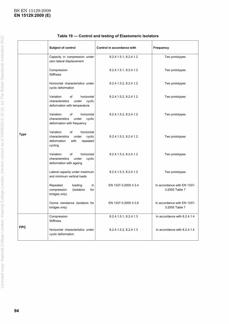
BS EN 15129:2009EN 15129:2009 (E)
94
Table 19 — Control and testing of Elastomeric Isolators
Subject of control
Control in accordance with Frequency
Type
Capacity in compression under zero lateral displacement Compression Stiffness Horizontal characteristics under cyclic deformation Variation of horizontal characteristics under cyclic deformation with temperature Variation of horizontal characteristics under cyclic deformation with frequency Variation of horizontal characteristics under cyclic deformation with repeated cycling Variation of horizontal characteristics under cyclic deformation with ageing Lateral capacity under maximum and minimum vertical loads Repeated loading in compression (isolators for bridges only) Ozone resistance (isolators for bridges only)
8.2.4.1.5.1, 8.2.4.1.2
8.2.4.1.5.1, 8.2.4.1.2
8.2.4.1.5.2, 8.2.4.1.2
8.2.4.1.5.2, 8.2.4.1.2
8.2.4.1.5.2, 8.2.4.1.2
8.2.4.1.5.2, 8.2.4.1.2
8.2.4.1.5.2, 8.2.4.1.2
8.2.4.1.5.3, 8.2.4.1.2
EN 1337-3:2005 4.3.4
EN 1337-3:2005 4.3.6
Two prototypes
Two prototypes
Two prototypes
Two prototypes
Two prototypes
Two prototypes
Two prototypes
Two prototypes
In accordance with EN 1337-3:2005 Table 7
In accordance with EN 1337-3:2005 Table 7
FPC
Compression Stiffness Horizontal characteristics under cyclic deformation
8.2.4.1.5.1, 8.2.4.1.3
8.2.4.1.5.2, 8.2.4.1.3
In accordance with 8.2.4.1.4
In accordance with 8.2.4.1.4
Lice
nsed
cop
y: Im
peria
l Col
lege
Lon
don,
Impe
rial C
olle
ge L
ondo
n, V
ersi
on c
orre
ct a
s of
24/
09/2
012
15:1
6, (
c) T
he B
ritis
h S
tand
ards
Inst
itutio
n 20
12

BS EN 15129:2009EN 15129:2009 (E)
95
Table 20 — Control and testing of Low damping elastomeric isolators for bridges subjected to small seismic actions
Subject of control Control in accordance with Frequency
Type
Horizontal stiffness under cyclic deformation
Lateral capacity under maximum and minimum vertical loads
8.2.4.1.5.2, 8.2.4.1.2
8.2.4.1.5.3, 8.2.4.1.2
Two prototypes
Two prototypes
Properties given in EN 1337-3:2005, Table 7 to be controlled in accordance with clause specified in that table and at frequency specified in that table.
FPC Properties shown in EN 1337-3:2005, Table 7 as items for ‘routine tests’ to be controlled in accordance with clause specified in that table and at frequency specified in EN 1337-3:2005, 8.2.3.
Table 21 — Control and testing of Curved and Flat Surface Sliders
Subject of control Control in accordance with Frequency
Type
Load bearing capacity
Frictional resistance force under service conditions
Sliding isolation tests
Tests as per EN 1337-2:2004 or relevant ETA
8.3.4.1.2
8.3.4.1.3
8.3.4.1.5
Table 15 of EN 1337-2 :2004 or the control plan of the relevant
ETA
Two prototypes
Two prototypes
Two prototypes
1 prototype
FPC
Load bearing capacity
Frictional resistance force under service conditions
Benchmark test P1
Tests as per EN 1337-2:2004 or relevant ETA
8.3.4.1.2, 8.3.4.2
8.3.4.1.3, 8.3.4.2
8.3.4.1.5, 8.3.4.2
Table 15 of EN 1337-2 :2004 or the control plan of the relevant
ETA
5 %
5 %
5 %
In accordance with Table 15 of EN 1337-2:2004 or the
control plan of the relevant ETA
10.2.2 Further type-testing
Whenever a change occurs in the design of the anti-seismic device, the raw material, or the production process, which would change the tolerances or requirements of the relevant Clauses 5 to 9 for one or more of the characteristics, the type tests shall be repeated for the appropriate characteristic(s). Li
cens
ed c
opy:
Impe
rial C
olle
ge L
ondo
n, Im
peria
l Col
lege
Lon
don,
Ver
sion
cor
rect
as
of 2
4/09
/201
2 15
:16,
(c)
The
Brit
ish
Sta
ndar
ds In
stitu
tion
2012

BS EN 15129:2009EN 15129:2009 (E)
96
Type tests shall also be required:
for the validation of new devices;
for the validation of existing devices, when materials are changed;
for the validation of existing devices in ranges of use outside those previously validated;
as specified in the relevant clauses of this European Standard.
All mechanical properties of the devices needed in the design for the anticipated service lifetime, together with their ranges of variation due to causes as given in 4.4.1, shall be determined by the type tests. Full-scale devices shall be required for these tests, unless otherwise specified in the relevant clauses of this European Standard. These tests shall include at least cycling tests, in the conditions of use in the seismic design situation, unless otherwise specified in the relevant clauses of this European Standard. Tests shall be done to establish the representative values of the properties.
The test report shall include at least the following items:
a) identification of the devices or test specimens (name of manufacturer, origin and number of device manufacturing batch);
b) dimensions, shape and arrangement of the devices or specimens;
c) date, type of test, its duration and any other relevant test conditions;
d) description of test equipment;
e) complete continuous graphical record of test results, where applicable;
f) description of the condition of the device or test specimen prior to and after testing;
g) any abnormal incidents occurring during the test;
h) statement that the test was performed in accordance with this European Standard.
NOTE It is recommended to include in the test report any operating details of the testing not considered in this European Standard but which may be useful to the designer or the owner.
10.3 Factory Production Control (FPC)
10.3.1 General
NOTE 1 A FPC system conforming to the following requirements of the relevant part(s) of EN ISO 9001:2008, and made specific to the requirements of this standard, is considered to satisfy the above requirements.
The manufacturer shall establish, document and maintain a FPC system to ensure that the manufactured products conform to the stated performance characteristics. The FPC system shall consist of procedures, regular inspections and tests and/or assessments and the use of the results for example to control raw and other incoming materials or components, equipment, the production process and the product.
The manufacturer shall be responsible for organising the effective implementation of the factory production control system. Tasks and responsibilities in the production control organisation shall be documented and this documentation shall be kept up to-date. In each factory the manufacturer may delegate the action to a person having the necessary authority to:
a) identify procedures to demonstrate conformity of the product at appropriate stages; Lice
nsed
cop
y: Im
peria
l Col
lege
Lon
don,
Impe
rial C
olle
ge L
ondo
n, V
ersi
on c
orre
ct a
s of
24/
09/2
012
15:1
6, (
c) T
he B
ritis
h S
tand
ards
Inst
itutio
n 20
12

BS EN 15129:2009EN 15129:2009 (E)
97
b) identify and record any instance of non-conformity;(c) identify procedures to correct instances of non conformity.
The manufacturer shall draw up and keep up-to-date documents defining the factory production control which he applies. The manufacturer's documentation and procedures shall be appropriate to the product and manufacturing process. All FPC systems shall achieve an appropriate level of confidence in the conformity of the product.
This involves:
a) the preparation of documented procedures and instructions relating to factory production control operations, in accordance with the requirements of the reference technical specification;
b) the effective implementation of these procedures and instructions;
c) the recording of these operations and their results;
d) the use of these results to correct any deviations, repair the effects of such deviations, treat any resulting instances of non-conformity and, if necessary, revise the FPC to rectify the cause of non-conformity.
The production control operations shall include some or all of the following operations:
e) the verification of raw materials and constituents;
f) the controls and tests to be carried out during manufacture according to a frequency laid down;
g) the verifications and tests to be carried out on finished products according to a frequency which may be laid down in the technical specifications and adapted to the product and its conditions of manufacture.
NOTE 2 The operations under b) centre as much on the intermediate states of the product as on manufacturing machines and their adjustment, and equipment, etc. These controls and tests and their frequency are chosen based on product type and composition, the manufacturing process and its complexity, the sensitivity of product features to variations in manufacturing parameters, etc.
The manufacturer shall have available the installations, equipment and personnel which enable him to carry out the necessary verifications and tests. He may, as may his agent, meet this requirement by concluding a sub-contracting agreement with one or more organizations or persons having the necessary skills and equipment.
The manufacturer shall have the responsibility to calibrate or verify and maintain the control, measuring or test equipment in good operating condition, whether or not it belongs to him, with a view to demonstrating conformity of the product with its technical specification. The equipment shall be used in conformity with the specification or the test reference system to which the specification refers.
NOTE 3 If necessary, monitoring is carried out of the conformity of intermediate states of the product and at the main stages of its production. This monitoring of conformity focuses where necessary on the product throughout the process of manufacture, so that only products having passed the scheduled intermediate controls and tests are dispatched.
The results of inspections, tests or assessments requiring action and any action taken shall be recorded. The action to be taken if control values or criteria are not met shall be recorded.
The extent and frequency of factory production control by the manufacturer shall be conducted in accordance with Table 16 to Table 21. In addition, it shall be checked by controlling the inspection certificates as listed in Tables 22 to 26 that the incoming raw material and components comply with this European Standard.
For combined devices, the extent and frequency of factory production control shall be such that the control and sampling frequency for each type of component within the combined device is equivalent to that specified for the component in the appropriate table in this clause, or in the conformity evaluation clause of the appropriate European Standard or in an equivalent ETA. The control and testing of the combined device shall
Lice
nsed
cop
y: Im
peria
l Col
lege
Lon
don,
Impe
rial C
olle
ge L
ondo
n, V
ersi
on c
orre
ct a
s of
24/
09/2
012
15:1
6, (
c) T
he B
ritis
h S
tand
ards
Inst
itutio
n 20
12

BS EN 15129:2009EN 15129:2009 (E)
98
also be in accordance with 9.4.3. In addition, it shall be checked that the raw materials and constituents for each component comply with this or other appropriate European Standard, or equivalent ETA by controlling the inspection certificates as listed in Tables 22 to 26, the conformity evaluation clause of the appropriate European Standard or in an equivalent ETA.
10.3.2 Raw materials and constituents
The specifications of all incoming raw materials and components shall be documented, as the inspection scheme for ensuring their conformity.
Compliance with the product requirements specified in 5.2.2, 5.3.2, 6.3, 7.2, 8.2.2, 8.3.2, 8.4.2, 9.2 shall be verified by means of inspection certificates in accordance with EN 10204 to the level stated in Tables 22 to 26. Where appropriate, compliance with the requirements specified in 9.2 shall be verified by means of inspection certificates in accordance with EN 10204 to the level stated in the conformity evaluation clause of other European Standards or in an equivalent ETA.
Table 22 — Specific testing of raw materials and constituents for Rigid Connection Devices
Type of inspection
certificate in accordance with
EN 10204
Subject of control Control in accordance with
Frequency FPC Test
3.1 Ferrous materials Certifications based on existing standards
Every batch 5.2.5
5.3.4.8 Viscous Fluid Certifications based on
existing standards
Plating Certifications based on existing standards
Other materials Certifications based on existing standards
Table 23 — Specific testing of raw materials and constituents for Velocity Dependent Devices
Type of inspection
certificate in accordance
with EN 10204
Subject of control Control in accordance with Frequency FPC Test
3.1 Ferrous materials Certifications based on existing standards
Every batch 7.4.3
Viscous Fluid Certifications based on existing standards
Plating Certifications based on existing standards
Other materials Certifications based on existing standards
Lice
nsed
cop
y: Im
peria
l Col
lege
Lon
don,
Impe
rial C
olle
ge L
ondo
n, V
ersi
on c
orre
ct a
s of
24/
09/2
012
15:1
6, (
c) T
he B
ritis
h S
tand
ards
Inst
itutio
n 20
12
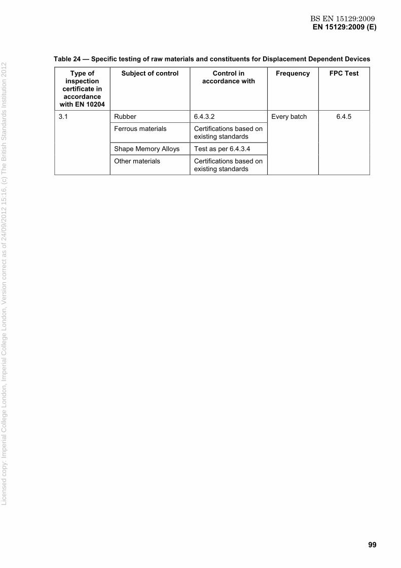
BS EN 15129:2009EN 15129:2009 (E)
99
Table 24 — Specific testing of raw materials and constituents for Displacement Dependent Devices
Type of inspection
certificate in accordance
with EN 10204
Subject of control Control in accordance with
Frequency FPC Test
3.1 Rubber 6.4.3.2 Every batch 6.4.5
Ferrous materials Certifications based on existing standards
Shape Memory Alloys Test as per 6.4.3.4
Other materials Certifications based on existing standards
Lice
nsed
cop
y: Im
peria
l Col
lege
Lon
don,
Impe
rial C
olle
ge L
ondo
n, V
ersi
on c
orre
ct a
s of
24/
09/2
012
15:1
6, (
c) T
he B
ritis
h S
tand
ards
Inst
itutio
n 20
12

BS EN 15129:2009EN 15129:2009 (E)
100
Table 25 — Specific testing of raw materials and constituents for Elastomeric Isolators including Low Damping Bridges Isolators subjected to small seismic actions
Type of inspection certificate in
accordance with EN 10204
Subject of control Control in accordance with Frequency FPC Test
3.1
High damping elastomers
Table 9 (except tear resistance)
Tear resistance (Table 9)
Table 12
Type test - once
FPC test - every batch
Type test - once
FPC test - every 5 batches
Type test - once
8.2.4.1.3
8.2.4.2.3
8.2.4.3.3
Low damping elastomers Table 8 (except tear resistance)
Tear resistance (Table 8)
Table 12 (except variation of damping not required)
Type test - once
FPC test - every batch
Type test - once
FPC test - every 5 batches
Type test - once
Low damping elastomers for bridge isolators subjected to small seismic actions
EN 1337-3:2005,
Table 1
Type test - once
FPC test according to EN 1337-3:2005,
Table 8
Polymer plug material
8.2.4.3.2
8.2.4.3.3
Type test - once
FPC - every batch
Lead plug 8.2.2.3 FPC - every batch
Steel plates EN 1337-3:2005, 4.4.3 FPC - every batch
Lice
nsed
cop
y: Im
peria
l Col
lege
Lon
don,
Impe
rial C
olle
ge L
ondo
n, V
ersi
on c
orre
ct a
s of
24/
09/2
012
15:1
6, (
c) T
he B
ritis
h S
tand
ards
Inst
itutio
n 20
12
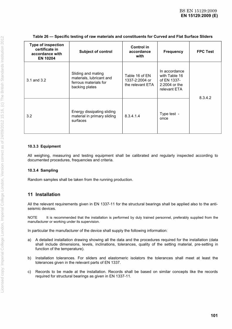
BS EN 15129:2009EN 15129:2009 (E)
101
Table 26 — Specific testing of raw materials and constituents for Curved and Flat Surface Sliders
Type of inspection certificate in
accordance with EN 10204
Subject of control Control in
accordance with
Frequency FPC Test
3.1 and 3.2
Sliding and mating materials, lubricant and ferrous materials for backing plates
Table 16 of EN 1337-2:2004 or the relevant ETA
In accordance with Table 16 of EN 1337-2:2004 or the relevant ETA
8.3.4.2
3.2 Energy dissipating sliding material in primary sliding surfaces
8.3.4.1.4 Type test - once
10.3.3 Equipment
All weighing, measuring and testing equipment shall be calibrated and regularly inspected according to documented procedures, frequencies and criteria.
10.3.4 Sampling
Random samples shall be taken from the running production.
11 Installation
All the relevant requirements given in EN 1337-11 for the structural bearings shall be applied also to the anti-seismic devices.
NOTE It is recommended that the installation is performed by duly trained personnel, preferably supplied from the manufacturer or working under its supervision.
In particular the manufacturer of the device shall supply the following information:
a) A detailed installation drawing showing all the data and the procedures required for the installation (data shall include dimensions, levels, inclinations, tolerances, quality of the setting material, pre-setting in function of the temperature).
b) Installation tolerances. For sliders and elastomeric isolators the tolerances shall meet at least the tolerances given in the relevant parts of EN 1337.
c) Records to be made at the installation. Records shall be based on similar concepts like the records required for structural bearings as given in EN 1337-11.
Lice
nsed
cop
y: Im
peria
l Col
lege
Lon
don,
Impe
rial C
olle
ge L
ondo
n, V
ersi
on c
orre
ct a
s of
24/
09/2
012
15:1
6, (
c) T
he B
ritis
h S
tand
ards
Inst
itutio
n 20
12

BS EN 15129:2009EN 15129:2009 (E)
102
12 In-service inspection
12.1 General requirements
All the relevant requirements given in EN 1337-10 for the structural bearings shall be applicable to the anti-seismic devices.
12.2 Regular inspection
In the regular inspection all the properties listed in Clause 5 of EN 1337-10:2003 shall be checked with the following addition:
Oil leakage (for Temporary Dynamic Connection Devices, Velocity Dependant Devices and all devices utilising fluids)
If an oil leakage is detected a Principal Inspection shall be performed.
12.3 Principal inspection
The principal inspection shall be carried out at less frequent intervals than the regular inspection and normally replaces one of them.
The first principal inspection shall be carried out within one year of the structure being put into service.
The principal inspection shall be repeated after any earthquake reaching the level of no failure requirement as defined in 4.1.1 a).
The specific checks for the different types of anti-seismic devices shall be defined by the manufacturer. For sliders and elastomeric bearings the specific checks shall meet at least the requirements given in EN 1337-10.
The records to be made at the Principal Inspection shall be defined by the manufacturer and shall be based on concepts similar to the records required for structural bearings as given in EN 1337-10.
Lice
nsed
cop
y: Im
peria
l Col
lege
Lon
don,
Impe
rial C
olle
ge L
ondo
n, V
ersi
on c
orre
ct a
s of
24/
09/2
012
15:1
6, (
c) T
he B
ritis
h S
tand
ards
Inst
itutio
n 20
12

BS EN 15129:2009EN 15129:2009 (E)
103
Annex A (informative)
Commentary to Clause 1: Scope
The modification of the seismic response of the structure may be obtained by increasing the fundamental period of the structure, by modifying the shape of the fundamental mode, by increasing the damping, by limiting the forces transmitted to the structure and/or introducing temporary connections that improve the overall seismic response of the structure. Other ways of modification may be envisaged.
There are several types of device that can be used to that end, each with different possibilities of location within the structure.
A popular way to modify the seismic response of the structure is to provide seismic isolation. In that case, the isolation units are usually located below the main mass of the structure and are arranged over the isolation interface. They can have a quasi-elastic behaviour, to increase the fundamental period of the structure, or a non linear softening behaviour, to limit the force transmitted to the structure.
A reduction of the structural response can also be obtained by damping devices, installed at different levels of the structure to dissipate energy.
The installation of temporary constraints, activated only by the fast movements due to seismic actions, can also contribute to a substantial improvement in the seismic response of a structure.
Combinations of devices of the types described above may also be used.
Isolators used for anti-seismic purposes often play the role of bearings in non-seismic situations. Therefore, they may also be governed by the requirements of EN 1337-1, EN 1337-2, EN 1337-3, EN 1337-5 and EN 1337-7.
The design of structures whose response is modified by anti-seismic devices is ruled by the structural Eurocodes. In the case of base-isolated structures, clause 10 of EN 1998-1:2004 applies, with additional requirements in EN 1998-2, for bridges.
This European standard sets rules for the design of anti-seismic devices, specific to the seismic situation. These devices have in general to sustain non-seismic situations; in these situations, they are ruled by Eurocodes and other European Standards.
Lice
nsed
cop
y: Im
peria
l Col
lege
Lon
don,
Impe
rial C
olle
ge L
ondo
n, V
ersi
on c
orre
ct a
s of
24/
09/2
012
15:1
6, (
c) T
he B
ritis
h S
tand
ards
Inst
itutio
n 20
12
BS EN 15129:2009EN 15129:2009 (E)
104
Annex B (informative)
Commentary to Clause 4: General design rules
B.1 Service life of a device
The service life of a device, as stated in 3.1, is given by the Owner in the Technical Specifications of the Project. The figure is based on declarations made by the device manufacturer as part of the validation procedure (see 4.6) or on the specific conditions of the project if the conditions given in the validation procedure do not apply. In that case, the service life is estimated from the results of accelerated tests and other evidence provided. If necessary, the service life can also take account of the lifetime of the structure, as given in the design specifications of the project or, in the absence of such specification, on general indications given in EN 1990. The service life of the devices may be less than the lifetime of the structure.
B.2 Basic requirements
Basic requirements concern both the structure and the devices, as their dynamic behaviour and their limit states cannot be completely dissociated. They have to be fully consistent with those set forth in EN 1998. Requirements and specific rules for the design of structures are given in EN 1998, while this European Standard covers additional requirements and specific rules for the design of devices.
Basic requirements for the structure are deemed to be satisfied if compliance criteria of subclause 2.2 of EN 1998-1:2004 are met.
B.3 Reliability differentiation
According to the corresponding parts of EN 1998, reliability differentiation for different types of buildings or civil engineering works is implemented by classifying structures into different importance categories. To each category, an importance factor γI is assigned and applied to the seismic action. The values of the factor γI are recommended in the corresponding parts of EN 1998.
This γI factor is included in the seismic actions effects on the devices.
B.4 Increased reliability
A γx factor is required by EN 1998-1 for isolators to cover an increased reliability of an isolation system and its recommended value is 1,2. National Authorities should specify the corresponding values for use in their territory. In EN 1998-2, the reliability factor is called γIS and its recommended value is 1,5.
In cases where no isolation system is used, but anti-seismic devices are present, it can still be justified to increase the reliability of the system by introducing a γx factor greater than 1, the value depending upon the function the devices play in the overall stability of the structure, the types of devices used and the future use of the structure. This European Standard gives additional recommendations for the values of γx according to the different types of device (except in the case of isolators where the values of the γx factor are given in Eurocode 8), to help the National Authorities in their choice, or the Owner or the Structural Engineer if no requirements exist.
Lice
nsed
cop
y: Im
peria
l Col
lege
Lon
don,
Impe
rial C
olle
ge L
ondo
n, V
ersi
on c
orre
ct a
s of
24/
09/2
012
15:1
6, (
c) T
he B
ritis
h S
tand
ards
Inst
itutio
n 20
12

BS EN 15129:2009EN 15129:2009 (E)
105
B.5 Requirements at the ULS
The device and its connections to the structure should be designed so that, for a seismic action beyond the design seismic action, there is no immediate catastrophic failure or immediate change in the properties sufficient to be detrimental to the dynamic behaviour of the structure.
After a seismic action corresponding to the design seismic situation, the replacement of the device should be possible, without either demolition or replacement of the structure or addition of parts to the structure. However, a very limited demolition in the vicinity of the anchorage (meaning approximately of the same size) is permitted. The replacement procedure should be described in the design documents as required in 4.3.4. Major interventions including larger demolitions and/or replacement of parts of the structure or the addition of new structural elements may be envisaged after a seismic action beyond the design level.
B.6 Requirements at the SLS
It is undesirable to have a structure that responds perceptibly under frequently occurring loads, such as time-dependent loads or wind. Therefore, additional measures should be taken, where isolation systems are used, to provide an adequate lateral stiffness against frequently occurring loads.
B.7 Structural analysis
Structural analysis in a seismic situation is, in principle, dealt with in EN 1998-1 and EN 1998-2.
The design seismic action is that defined in clause 3 of EN 1998-1:2004, using an elastic response spectrum or related accelerograms. Whenever a behaviour factor is applicable, a design spectrum is used.
According to the types of devices concerned, the dynamic structural analysis is performed either by using a response spectrum or by using a time history analysis.
The use of a response spectrum in connection with an equivalent linear behaviour is ruled by conditions given in EN 1998-1:2004 subclause 10.9.2, in particular as concerns limitation of damping. When these conditions are not met, a time-history structural analysis should be used. It is strongly recommended that a time-history analysis is performed when the equivalent damping ratio related to hysteretic energy dissipation is higher than 15 %.
The main characteristics of an anti-seismic device that should be carefully assessed for the use in the design of the structure are its flexibility, its damping capacity and its self-centring capability.
Effects of actions on devices and their connections to the structure in the seismic situation are determined by the application of the structural analysis, as defined in the corresponding parts of EN 1998. Design effects of actions should take into account additional requirements that are given in the corresponding parts of EN 1998 to fulfil capacity design principles.
Actions applied to the devices and their connections to the structure in the different design situations, including the seismic situations, are the basis for the design requirements of the devices and their connections to the structure.
B.8 Material properties
A suitable choice in the sets of properties (UBDP and LBDP) may result in only two enveloping structural analyses.
For the design of devices, it is reminded that, according to EN 1990, partial factors γm should be applied to the constitutive material strength and/or ultimate strain. γm is related to the distribution of strength, in terms of
Lice
nsed
cop
y: Im
peria
l Col
lege
Lon
don,
Impe
rial C
olle
ge L
ondo
n, V
ersi
on c
orre
ct a
s of
24/
09/2
012
15:1
6, (
c) T
he B
ritis
h S
tand
ards
Inst
itutio
n 20
12

BS EN 15129:2009EN 15129:2009 (E)
106
probability and depends on the material used. In the cases where an analytical verification of the device, where all materials are checked locally, is not performed (for instance in the cases where the verification is based on testing on a sufficient number of samples), a similar γ factor can be applied on the resistance of the device as a whole or on parts of it. A different index is then applied to γ (e.g. γb for the full device).
B.9 Re-centring capability
The purpose of the re-centring capability requirement is not so much that of limiting residual displacement at the end of a seismic event, but instead that of preventing cumulative displacements during the event, as indicated in Figures B.1 and B.2.
A requirement for re-centring capability is necessary to take into account unpredictable adverse factors, such as sliding bearings’ out of level.
Re-centring assumes particular relevance in structures located in close proximity to a fault, where earthquakes characterised by highly asymmetric time histories are expected (Near Field or Fling effect).
Figure B.1 — Seismic Isolation System with adequate self-centering capability
Figure B.2 — Seismic Isolation System with poor self-centering capability
Among the four fundamental functions of a seismic isolation system, energy dissipation and re-centring capability are two opposing functions and their relative importance depends primarily on the case under examination.
The criterion given in 4.4.3 is based on energy concepts and thus couples very well with the intrinsic nature of the phenomenon in question (the earthquake).The suggested verification requirement can be easily translated in formulae or design criteria for each type of isolator or isolation system.
It should be noted that re-centring capability is a characteristic of the entire isolation system, not necessarily of each of its components (e.g. the single isolator).The calculation of reversibly stored energy ES shall take into account also those elements of the structure that influence its response, such as a slender pier solidly connected to the bridge deck that undergoes flexural deformation during a seismic event. In this case the pier acts as a spring and thus it may be considered for all practical purposes like a supplemental re-centring device. A second example of structural elements that influence the response of the structure are the hangers of suspended bridges. In this case, the stored energy is of the potential type.
The proposed criterion has shown itself capable of a preliminary definition of an isolation system’s characteristics before the undertaking of a step-by-step non linear analysis. The latter still represents the most valid method to verify an isolation system’s re-centring capability inasmuch as it permits quantification of the residual displacement as well as revealing growth of any cumulative displacements during a seismic event.
Lice
nsed
cop
y: Im
peria
l Col
lege
Lon
don,
Impe
rial C
olle
ge L
ondo
n, V
ersi
on c
orre
ct a
s of
24/
09/2
012
15:1
6, (
c) T
he B
ritis
h S
tand
ards
Inst
itutio
n 20
12
BS EN 15129:2009EN 15129:2009 (E)
107
Annex C (informative)
Commentary to Clause 5: Rigid connection devices
C.1 Functional requirements
A TCD is fully defined when the Structural Engineer specifies the following design magnitudes:
design force (kN);
activation (lock-up) velocity (mm/s);
maximum resistance to slow movements (kN);
specified slow movement capacity (mm/s);
maximum stroke (± mm);
thermal stroke (± mm);
tolerances;
rotation angle (± degrees);
service temperature range;
where the maximum stroke includes displacements due to any slowly occurring effect (thermal, creep and shrinkage effects) and dynamic effects, and additional adjusting length (whenever required).
The activation velocity should be estimated as about 1 % of the maximum relative velocity expected at the ends of the TDC.
The first requirement ensures that the force developed by the unit at a velocity equal to or less than the activation velocity shall be at least equal to the design force in the entire range of environmental temperature.
The second requirement ensures that, when the device is subjected to slowly applied relative movements at its ends, such as thermal expansion/contraction, its reaction does not exceed the Design Maximum Resistance to slow movements force in the entire range of environmental temperature.
This requirement aims to avoid fatigue loads acting on structural members.
The third requirement aims to verify that whenever the TCDs should be subjected to non-seismic impulsive loads, such as braking forces for devices installed on bridges, an additional evaluation of the performance should be made in terms of force, velocity, stiffness and number of load cycles.
C.2 Material properties
Silicone fluids provide for very stable rheological characteristics. In very few cases, when the frequency of the structural movements may induce severe wearing of the seals and/or in extra-size units where stick-slip phenomena – induced by the weight and slenderness of the unit itself – could be expected, the lubricating Li
cens
ed c
opy:
Impe
rial C
olle
ge L
ondo
n, Im
peria
l Col
lege
Lon
don,
Ver
sion
cor
rect
as
of 2
4/09
/201
2 15
:16,
(c)
The
Brit
ish
Sta
ndar
ds In
stitu
tion
2012

BS EN 15129:2009EN 15129:2009 (E)
108
capacity of hydrocarbon-based fluids may be exploited and their use may be allowed under approval of the Structural Engineer.
C.3 Design Requirements
The proposed partial factors are correlated with the earthquake period of return.
Whenever the TCD is equipped with an over-load relief system such as relief valves acting to limit the excess of pressure into the device when the design condition is exceeded, lower safety factor can be used.
The most detrimental acceleration acting on the device, with the exception of the axial one, is vertical. In fact, the sealing system and the device itself should be designed to withstand the effect of the TCD’s self-weight plus the vertical acceleration.
The connections between the TCD and the structure are designed to withstand a force equal to 1,1 γRd FUB or 1,5 γRd FUB, where γRd is equal to 1,1.
The TCD components shall be designed to withstand a force equal to γRd FUB or 1,5 γRd FUB.
Key X Displacement Y Force 1 Nominal Curve
2 1,1 γRd FUB or 1,5 γRd FUB 3 1,1 FUB or 1,5 FUB 4 FUB
Figure C.1 — Strength Verification
C.4 Testing
C.4.1 General
TCDs provide the expected behaviour over the full service temperature range.
Considering the available technologies, the most critical issues are related to the drag force produced by the TCD at the lowest expected temperature (because the fluid viscosity increases with decrease of temperature), and the design stiffness at the highest expected temperature (at which the fluid viscosity leasts).
Lice
nsed
cop
y: Im
peria
l Col
lege
Lon
don,
Impe
rial C
olle
ge L
ondo
n, V
ersi
on c
orre
ct a
s of
24/
09/2
012
15:1
6, (
c) T
he B
ritis
h S
tand
ards
Inst
itutio
n 20
12
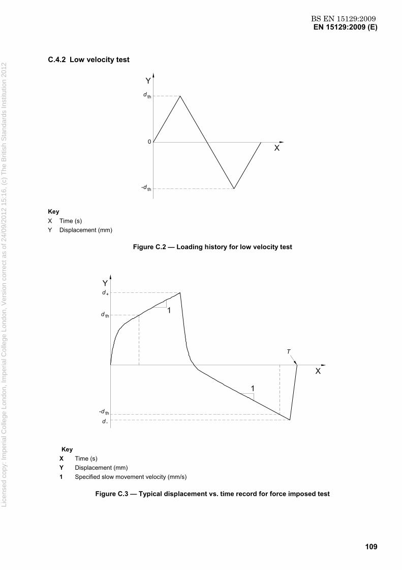
BS EN 15129:2009EN 15129:2009 (E)
109
C.4.2 Low velocity test
Key X Time (s) Y Displacement (mm)
Figure C.2 — Loading history for low velocity test
Key X Time (s) Y Displacement (mm) 1 Specified slow movement velocity (mm/s)
Figure C.3 — Typical displacement vs. time record for force imposed test
Lice
nsed
cop
y: Im
peria
l Col
lege
Lon
don,
Impe
rial C
olle
ge L
ondo
n, V
ersi
on c
orre
ct a
s of
24/
09/2
012
15:1
6, (
c) T
he B
ritis
h S
tand
ards
Inst
itutio
n 20
12

BS EN 15129:2009EN 15129:2009 (E)
110
C.4.3 Seal Wear Test
TCDs are typically required to function during the earthquake, having for years experienced only thermally induced movements. At the time of the earthquake, the sealing system must guarantee a proper functioning even after a long “resting” period. Seal wear must not compromise the behaviour of the entire structure.
C.4.4 Impulsive Load Test
The 0,5 s time required to reach the maximum force aims just to provide a shock-like effect on the TCD. From the testing point of view, this loading time can generally be easily achieved. TCDs characterised by exceptional loads and strokes may be tested with a longer loading time.
Key X Time (s) Y Force (kN)
Figure C.4 — Loading history for Impulsive Load Test
Key X Time (s) Y Displacement (mm) 1 Activation velocity
Figure C.5 — Typical Displacement vs. Time Record of Impulsive Load Test
Lice
nsed
cop
y: Im
peria
l Col
lege
Lon
don,
Impe
rial C
olle
ge L
ondo
n, V
ersi
on c
orre
ct a
s of
24/
09/2
012
15:1
6, (
c) T
he B
ritis
h S
tand
ards
Inst
itutio
n 20
12
BS EN 15129:2009EN 15129:2009 (E)
111
C.4.5 Overload Test
The object of the test is to verify the TCD’s behaviour whenever the design load is exceeded.
A TCD behaves as a dynamically activated spring element, thus whenever the actual earthquake exceeds the design level, the resulting force transmitted through the device may exceed the design one. If the TCD is coupled to ductile elements, the transmitted force is limited by the yielding of such elements. Whenever a certain level of force is critical for the ultimate performance of the structure, the Structural Engineer may prescribe the utilization of relief valves in order to limit the maximum force transmitted through the unit.
C.4.6 Cyclic Load Test
The object of the test is to evaluate the reliability of the TCD’s behaviour during the earthquake.
A sinusoidal (time-dependent) time history lasting for a sufficient period of time is needed in 5.3.4.7.
Lice
nsed
cop
y: Im
peria
l Col
lege
Lon
don,
Impe
rial C
olle
ge L
ondo
n, V
ersi
on c
orre
ct a
s of
24/
09/2
012
15:1
6, (
c) T
he B
ritis
h S
tand
ards
Inst
itutio
n 20
12

BS EN 15129:2009EN 15129:2009 (E)
112
Annex D (informative)
Commentary to Clause 6: Displacement Dependent Devices
D.1 Categories of Non Linear Devices (NLD)
NLD are mainly used in passive control systems, whose functioning is based on the increase in the flexibility of the structural system and/or on the energy dissipation capability.
Different categories of devices can be identified, according to the main features of their force-displacement cycles, deriving from the peculiar characteristics of different materials and mechanisms.
A first classification can be made according to their capability to dissipate energy and includes the following categories:
Energy Dissipating Devices (EDD), when ζ > 15 % ;
Non Linear Elastic Devices (NLED), when ζ ≤ 15 %.
A second classification can be made according to the variability of their stiffness as a function of the displacement, including the following categories:
Hardening Devices (HD), when K2/K1 > 1;
Softening Devices (SD), when K2/K1 ≤ 1.
A third classification can be made according to the re-centring capability of the device, i.e. the capability to recover its initial shape when the applied external force is zero or, when it is a part of a structural system, to make the system to recover its initial shape or limiting residual displacement, at the end of an earthquake. The following categories can be singled out:
Dynamically [Weakly] Re-Centring Devices (DRD), when the reversibly stored energy (elastic strain energy and potential energy) Es is greater than 25 % the energy dissipated by hysteretic deformation Eh;
Statically [strongly] Re-Centring Devices (RCD), when the displacement at zero force is less than 10 % the maximum attained displacement;
Supplemental Re-Centring Devices (SRCD), when the displacement at zero force is less than 10 % the maximum attained displacement, even when an external force at least equal to 10 % of the maximum force resist the recovering of the initial configuration of the device.
EDDs are normally softening devices based either on the hysteretic properties of metals (steel, lead, shape memory alloys) or on the frictional resistance between suitably treated surfaces. EDD can be also formed by using special shape memory alloys.
NLEDs can be either softening or hardening devices. They are sometimes based on the elastic property of special high-strength steel, some others on rubber under compression, or on the superelasticity of shape memory alloys. Their non linear behaviour is sometimes based on geometrical non linear effects due to the peculiar shape of their core elements. Other types of devices can be classified into this category, provided that the requirements given in this clause are fulfilled.
Lice
nsed
cop
y: Im
peria
l Col
lege
Lon
don,
Impe
rial C
olle
ge L
ondo
n, V
ersi
on c
orre
ct a
s of
24/
09/2
012
15:1
6, (
c) T
he B
ritis
h S
tand
ards
Inst
itutio
n 20
12
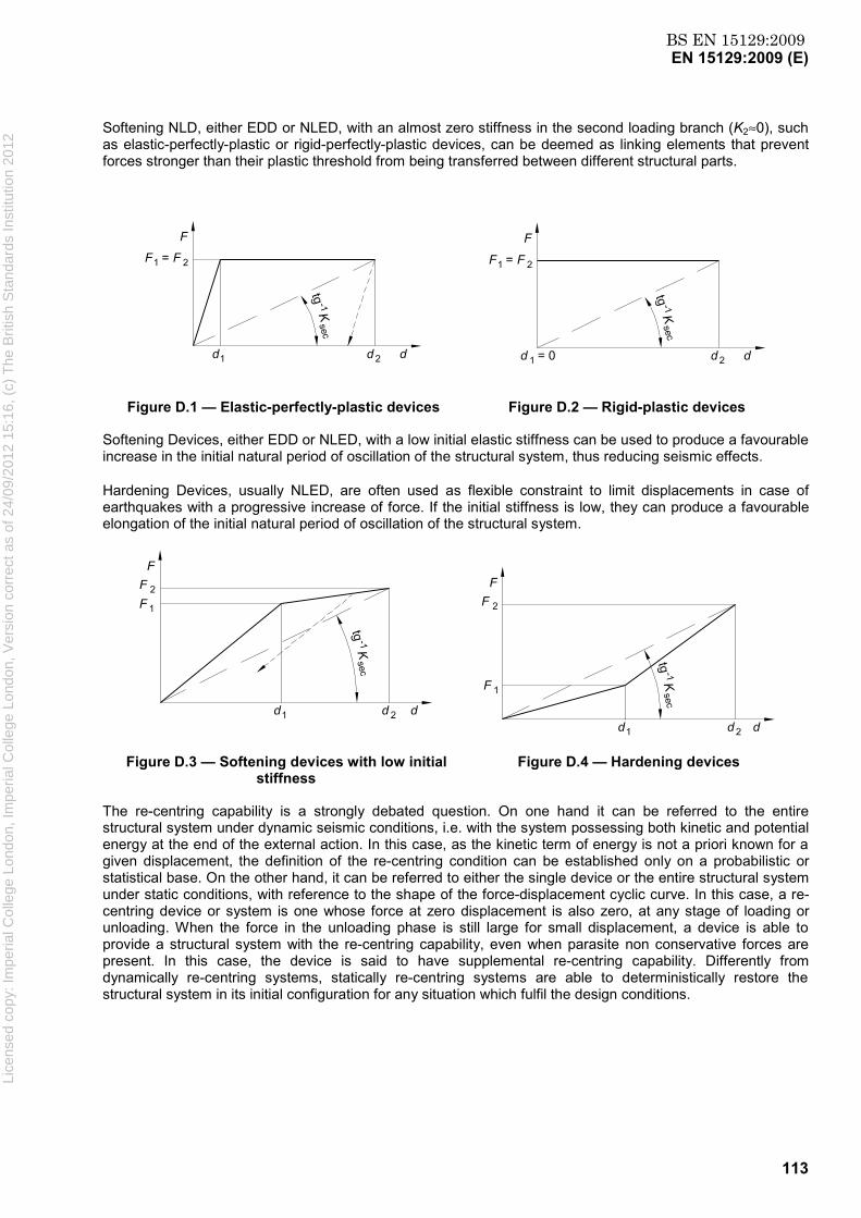
BS EN 15129:2009EN 15129:2009 (E)
113
Softening NLD, either EDD or NLED, with an almost zero stiffness in the second loading branch (K2≈0), such as elastic-perfectly-plastic or rigid-perfectly-plastic devices, can be deemed as linking elements that prevent forces stronger than their plastic threshold from being transferred between different structural parts.
Figure D.1 — Elastic-perfectly-plastic devices Figure D.2 — Rigid-plastic devices
Softening Devices, either EDD or NLED, with a low initial elastic stiffness can be used to produce a favourable increase in the initial natural period of oscillation of the structural system, thus reducing seismic effects.
Hardening Devices, usually NLED, are often used as flexible constraint to limit displacements in case of earthquakes with a progressive increase of force. If the initial stiffness is low, they can produce a favourable elongation of the initial natural period of oscillation of the structural system.
Figure D.3 — Softening devices with low initial stiffness
Figure D.4 — Hardening devices
The re-centring capability is a strongly debated question. On one hand it can be referred to the entire structural system under dynamic seismic conditions, i.e. with the system possessing both kinetic and potential energy at the end of the external action. In this case, as the kinetic term of energy is not a priori known for a given displacement, the definition of the re-centring condition can be established only on a probabilistic or statistical base. On the other hand, it can be referred to either the single device or the entire structural system under static conditions, with reference to the shape of the force-displacement cyclic curve. In this case, a re-centring device or system is one whose force at zero displacement is also zero, at any stage of loading or unloading. When the force in the unloading phase is still large for small displacement, a device is able to provide a structural system with the re-centring capability, even when parasite non conservative forces are present. In this case, the device is said to have supplemental re-centring capability. Differently from dynamically re-centring systems, statically re-centring systems are able to deterministically restore the structural system in its initial configuration for any situation which fulfil the design conditions.
Lice
nsed
cop
y: Im
peria
l Col
lege
Lon
don,
Impe
rial C
olle
ge L
ondo
n, V
ersi
on c
orre
ct a
s of
24/
09/2
012
15:1
6, (
c) T
he B
ritis
h S
tand
ards
Inst
itutio
n 20
12

BS EN 15129:2009EN 15129:2009 (E)
114
Statically Re-Centring Device Supplemental Re-Centring Device
Figure D.5 — Re-centring devices
D.2 Examples of linear devices — Elastomeric shear-strained devices
Devices similar to elastomeric isolators that do not carry vertical load are linear devices. Like elastomeric isolators, they are made of one or several layers of elastomer, which are strained in shear, while keeping parallel the upper and lower end plate of the device, connecting the relatively moving parts of a structure. According to the properties of the elastomeric compound, this device can exhibit different stiffness and damping properties, which usually fall into the defined range of linear devices.
D.3 Examples of non linear devices
D.3.1 Buffer
The buffer is a rubber-based elastic device capable of providing the structure with a force vs. deformation curve. The device thus has an elastic behaviour, but in general not a linear one. Actually, its linearity depends on the range of deformation in which the device works. This behaviour is obtained by means of a certain number of specially designed elastomeric discs, each of them vulcanised to two external steel plates. The device is designed so that the elastomeric discs are always subjected to compression, for movements in both directions. This is achieved by means of the particular rods arrangement, which allows the discs to be always compressed, no matter of the direction of the seismic forces.
The buffers are used in bridges to take horizontal loads, at abutments and/or between adjacent decks where expansion joints are located.
D.3.2 Steel hysteretic energy dissipating devices
These devices have high energy dissipating capability, which relies on the hysteretic behaviour of mild steel core elements strained in bending, shear or torsion, or even in a combination of them, well beyond the elastic limit. The elements are so shaped as to have a uniform strain distribution in their parts deputed to the energy dissipation function and, then, to maximize their low-cycle fatigue resistance. They are normally used as part of seismic isolation systems in bridges and buildings or as main components of energy dissipating bracing systems.
In the case of strong earthquakes, whose intensity is greater than the design earthquake, the device should be inspected to check whether the replacement of the device or of the core elements is required.
D.3.3 Buckling Restrained Braces
These devices are normally used as main components of energy dissipating bracing systems with high energy dissipating capability. They are based on the hysteretic behaviour of mild steel elements axially strained in
Lice
nsed
cop
y: Im
peria
l Col
lege
Lon
don,
Impe
rial C
olle
ge L
ondo
n, V
ersi
on c
orre
ct a
s of
24/
09/2
012
15:1
6, (
c) T
he B
ritis
h S
tand
ards
Inst
itutio
n 20
12

BS EN 15129:2009EN 15129:2009 (E)
115
tension and compression well beyond the elastic limit. The elements are so restrained (usually by an external concrete cylinder) as to avoid buckling in compression. In the case of strong earthquakes, whose intensity is greater than the design earthquake, the device should be inspected to check whether the replacement of the device or of the core elements is required.
D.3.4 SMA Re-centring Devices
These devices are normally used as main components of either seismic isolation systems or re-centring / energy dissipating bracing systems. They are based on the superelastic behaviour of Shape Memory Alloy wires in the austenitic state. To avoid buckling, wires are arranged in such a way as to make them work only under tensile loads. These devices have mainly a re-centring function, but when the SMA wires are used to form a counteracting SMA spring, they can also provide significant effective damping.
Lice
nsed
cop
y: Im
peria
l Col
lege
Lon
don,
Impe
rial C
olle
ge L
ondo
n, V
ersi
on c
orre
ct a
s of
24/
09/2
012
15:1
6, (
c) T
he B
ritis
h S
tand
ards
Inst
itutio
n 20
12
BS EN 15129:2009EN 15129:2009 (E)
116
Annex E (informative)
Commentary to Clause 7: Velocity Dependent Devices
E.1 Functional requirements
A Viscous Damper is fully defined when the Structural Engineer specifies the following main design values:
maximum force (kN);
maximum stroke (± mm);
maximum velocity (m/s);
damping constant C (kN/(m/s)α);
exponent α of the constitutive law;
stiffness K (kN/m);
pre-load Fo;
tolerances;
rotation angle (± degrees);
environmental temperature range.
A typical constitutive law of a Fluid Viscous Damper is of the type:
F = Cvα . (E.1)
FVDs providing for a very large stroke are better represented by a Maxwell model (spring and damper in series) whose elastic characteristic describes the effect of the fluid compressibility.
The latter is important if the Energy Dissipation Capacity needs to be evaluated.
A typical constitutive law of a Fluid Spring Damper is of the type:
F = Fo+kx+Cvα . (E.2)
Thus, FSDs are better represented by a Kelvin-Vöigt model (spring and damper in parallel) where the elastic stiffness describes the effect of the fluid compressibility and Fo is the pre-load.
It is pertinent to note that any type of anti-seismic device accumulates or dissipates energy in all four forms of the well-known energy balance equation and the classification into FVDs and FSDs takes into account the dominant form of energy.
For example, a Viscous Damper:
i) accumulates elastic energy through deformation of its mechanical components and the compressibility of the viscous fluid (dependence on displacement);
Lice
nsed
cop
y: Im
peria
l Col
lege
Lon
don,
Impe
rial C
olle
ge L
ondo
n, V
ersi
on c
orre
ct a
s of
24/
09/2
012
15:1
6, (
c) T
he B
ritis
h S
tand
ards
Inst
itutio
n 20
12

BS EN 15129:2009EN 15129:2009 (E)
117
ii) accumulates kinetic energy in its moving parts, i.e. piston (dependence on velocity);
iii) dissipates energy hysteretically into the gaskets through friction (dependence on displacement);
iv) dissipates energy viscously by forcing fluid flow through orifice or valve systems (dependence on velocity).
When the fourth term dominates, the device is classified as a “Fluid Viscous Damper” and the constants K and Fo may be neglected.
When both the first and the fourth terms are significant, the device is classified as a “Fluid Spring Damper”.
The amount of energy at play in a structure during a design level seismic event may range from 1 MJ to 50 MJ. The possible magnitude of the energy involved raises the fundamental question: “Will the anti-seismic device be significantly damaged by the energy it dissipates within itself during an earthquake?” Only a very limited fraction (1-5 %) of the large amount of mechanical energy it has to dissipate in the form of heat can be transferred to the environment by convection and conduction during the earthquake, and thus the device shall be able to absorb the heat produced and withstand the substantial increase in its temperature.
In the following figures, typical plots of FVD and FSD constitutive laws are reported.
Key X Normalized Velocity (%) Y Normalized Force (%) 1 Upper Bound 2 Lower Bound 3 Force vs. Velocity Characteristic Curve
Figure E.1 — Typical force vs. velocity FVD output envelope
Lice
nsed
cop
y: Im
peria
l Col
lege
Lon
don,
Impe
rial C
olle
ge L
ondo
n, V
ersi
on c
orre
ct a
s of
24/
09/2
012
15:1
6, (
c) T
he B
ritis
h S
tand
ards
Inst
itutio
n 20
12

BS EN 15129:2009EN 15129:2009 (E)
118
Key X Normalized Displacement (%) Y Normalized Force (%)
Figure E.2 — Force vs. displacement FSD output envelope (sinusoidal input)
E.2 Design Requirements
Exceeding the design level velocity has an effect that differs according to the characteristics of the Viscous Damper.
Figure E.3 illustrates a comparison of the effect of exceeding the design velocity vd by 50 % between two devices with different exponents α.
Lice
nsed
cop
y: Im
peria
l Col
lege
Lon
don,
Impe
rial C
olle
ge L
ondo
n, V
ersi
on c
orre
ct a
s of
24/
09/2
012
15:1
6, (
c) T
he B
ritis
h S
tand
ards
Inst
itutio
n 20
12

BS EN 15129:2009EN 15129:2009 (E)
119
Key X Velocity Y Force 1 Upper Bound 2 Force Vs Velocity Characteristic Curve
Figure E.3 — Effect of exceeding design velocity upon two devices with different exponent αααα
for α = 1,0 (linear damper) Fmax = (1+0,15) × 1,5 1 Fd = 1,725 Fd (E.3)
for α = 0,1 Fmax = (1+0,15) × 1,5 0,1 Fd = 1,198 Fd (E.4)
In conclusion, the over-strength factor depends on both the tolerance and the exponent α of the constitutive law.
The connections between the FD/FSD and the structure shall be designed to withstand a force equal to γRd⋅ γv⋅FUB, where γRd is equal to 1,1.
The FD/FSD components shall be designed to withstand a force equal to γv⋅FUB.
Lice
nsed
cop
y: Im
peria
l Col
lege
Lon
don,
Impe
rial C
olle
ge L
ondo
n, V
ersi
on c
orre
ct a
s of
24/
09/2
012
15:1
6, (
c) T
he B
ritis
h S
tand
ards
Inst
itutio
n 20
12
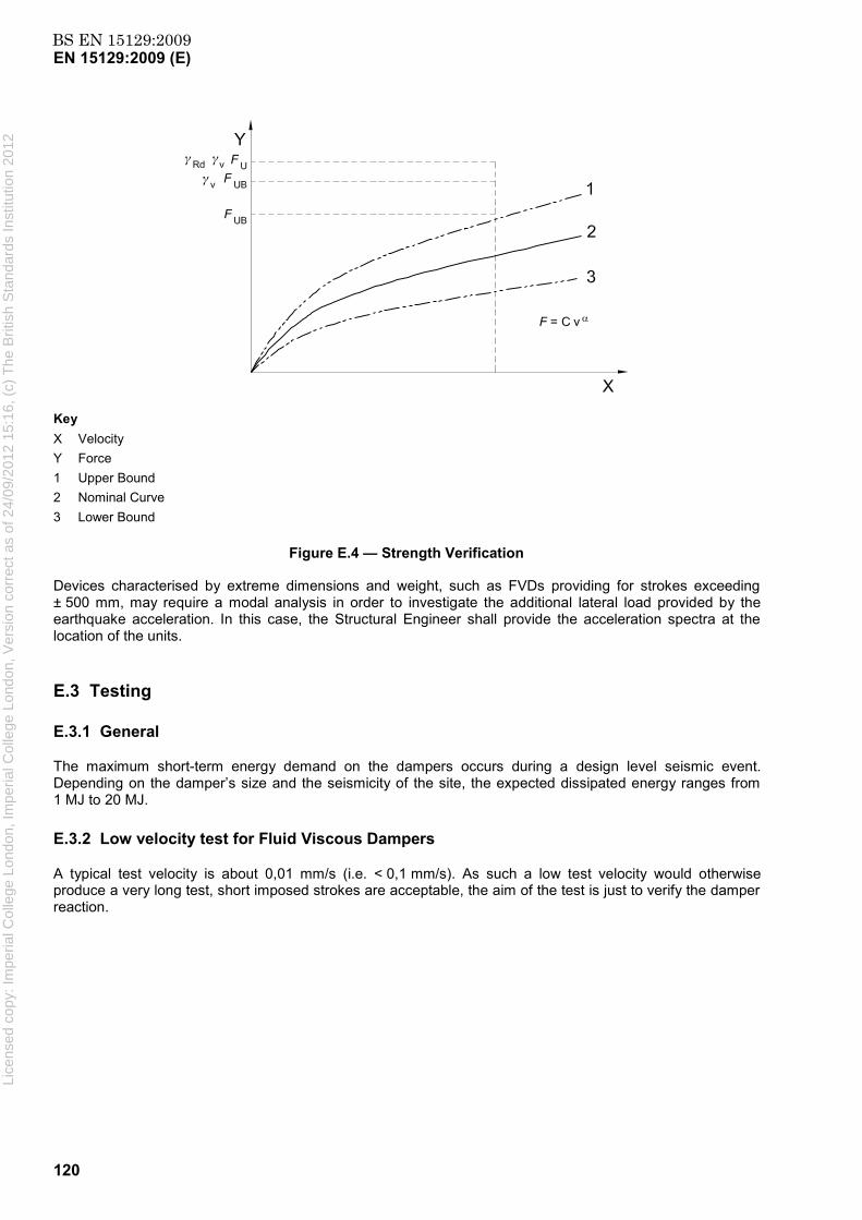
BS EN 15129:2009EN 15129:2009 (E)
120
Key X Velocity Y Force 1 Upper Bound 2 Nominal Curve 3 Lower Bound
Figure E.4 — Strength Verification
Devices characterised by extreme dimensions and weight, such as FVDs providing for strokes exceeding ± 500 mm, may require a modal analysis in order to investigate the additional lateral load provided by the earthquake acceleration. In this case, the Structural Engineer shall provide the acceleration spectra at the location of the units.
E.3 Testing
E.3.1 General
The maximum short-term energy demand on the dampers occurs during a design level seismic event. Depending on the damper’s size and the seismicity of the site, the expected dissipated energy ranges from 1 MJ to 20 MJ.
E.3.2 Low velocity test for Fluid Viscous Dampers
A typical test velocity is about 0,01 mm/s (i.e. < 0,1 mm/s). As such a low test velocity would otherwise produce a very long test, short imposed strokes are acceptable, the aim of the test is just to verify the damper reaction.
Lice
nsed
cop
y: Im
peria
l Col
lege
Lon
don,
Impe
rial C
olle
ge L
ondo
n, V
ersi
on c
orre
ct a
s of
24/
09/2
012
15:1
6, (
c) T
he B
ritis
h S
tand
ards
Inst
itutio
n 20
12
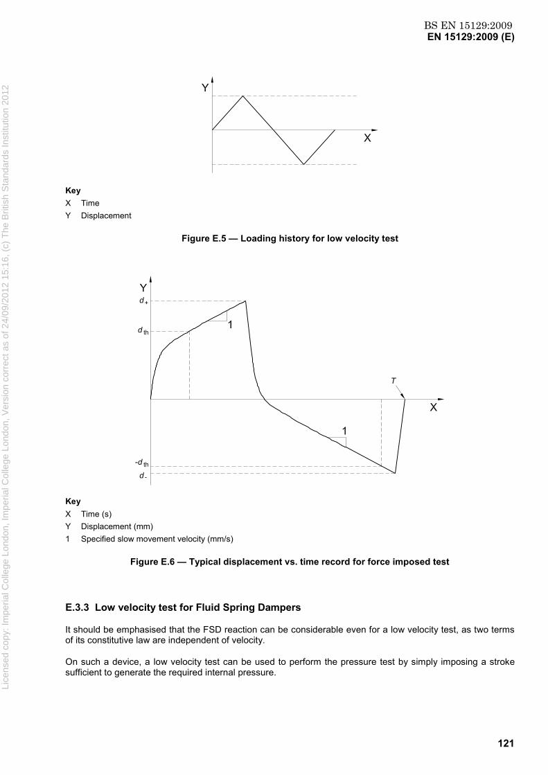
BS EN 15129:2009EN 15129:2009 (E)
121
Key X Time Y Displacement
Figure E.5 — Loading history for low velocity test
Key X Time (s) Y Displacement (mm) 1 Specified slow movement velocity (mm/s)
Figure E.6 — Typical displacement vs. time record for force imposed test
E.3.3 Low velocity test for Fluid Spring Dampers
It should be emphasised that the FSD reaction can be considerable even for a low velocity test, as two terms of its constitutive law are independent of velocity.
On such a device, a low velocity test can be used to perform the pressure test by simply imposing a stroke sufficient to generate the required internal pressure.
Lice
nsed
cop
y: Im
peria
l Col
lege
Lon
don,
Impe
rial C
olle
ge L
ondo
n, V
ersi
on c
orre
ct a
s of
24/
09/2
012
15:1
6, (
c) T
he B
ritis
h S
tand
ards
Inst
itutio
n 20
12

BS EN 15129:2009EN 15129:2009 (E)
122
E.3.4 Constitutive law test for Fluid Viscous Dampers
For the sake of simplicity, the test should be performed imposing a triangular wave loading history. This input is suggested because of the ease of reading the output damper reaction. With a sinusoidal test input the maximum imposed velocity is achieved only for an instant. Nevertheless, should the triangular wave loading history induce a too high peak of acceleration, a sinusoidal time history may be used.
Key X d (mm) Y F (kN)
Figure E.7 — Typical force vs. displacement hysteresis loop (at constant velocity)
E.3.5 Constitutive law test for Fluid Spring Dampers
For sake of simplicity, the test is performed imposing a triangular wave loading history. This input is suggested because of reading the output spring damper reaction. With a sinusoidal test input the maximum imposed velocity is achieved only for an instant. Nevertheless, should the triangular wave loading history induce a too high peak of acceleration, a sinusoidal time history may be used.
Key X d (mm) Y F (kN)
Figure E.8 — Typical force vs. displacement hysteresis loop (at constant velocity, F0=0)
Lice
nsed
cop
y: Im
peria
l Col
lege
Lon
don,
Impe
rial C
olle
ge L
ondo
n, V
ersi
on c
orre
ct a
s of
24/
09/2
012
15:1
6, (
c) T
he B
ritis
h S
tand
ards
Inst
itutio
n 20
12

BS EN 15129:2009EN 15129:2009 (E)
123
Key X d (mm) Y F (kN)
Figure E.9 – Typical force vs. displacement hysteresis loop (at constant velocity, F0≠0)
E.3.6 Damping efficiency test
The dissipative efficiency of any energy dissipating anti-seismic device is defined as the ratio between the area of the measured force-displacement hysteresis loop and the corresponding theoretical value. The efficiency is expressed in mathematical terms as:
( )∫=
dxvxFEDC
,η (E.5)
where, F(x,v) and x are the force and the displacement respectively and EDC is Energy Dissipation per Cycle.
In the case of Fluid Viscous Dampers, the force F(v) depends predominantly on the imposed velocity. Therefore, the energy dissipation efficiency η depends on the type of imposed input. A sinusoidal displacement input is conventionally adopted in the evaluation of the energy dissipation efficiency of viscous dampers. As already mentioned, for the correct evaluation of the theoretical Energy Dissipation per Cycle (EDC) a Maxwell model should be used. The utilisation of a simple non linear force vs. velocity constitutive law (dash-pot model) overestimates the theoretical energy dissipation capacity (see Figure E.10).
Lice
nsed
cop
y: Im
peria
l Col
lege
Lon
don,
Impe
rial C
olle
ge L
ondo
n, V
ersi
on c
orre
ct a
s of
24/
09/2
012
15:1
6, (
c) T
he B
ritis
h S
tand
ards
Inst
itutio
n 20
12

BS EN 15129:2009EN 15129:2009 (E)
124
Key X Normalized Displacement (%) Y Normalized Force (%) 1 Maxwell Model 2 Dash-Pot Model
Figure E.10 — Comparison between a simple non linear dash-pot and a Maxwell model for Fluid Viscous Dampers (*)
(*) The shape of the plot corresponding to a Maxwell model has been magnified for the sake of clarification.
Lice
nsed
cop
y: Im
peria
l Col
lege
Lon
don,
Impe
rial C
olle
ge L
ondo
n, V
ersi
on c
orre
ct a
s of
24/
09/2
012
15:1
6, (
c) T
he B
ritis
h S
tand
ards
Inst
itutio
n 20
12
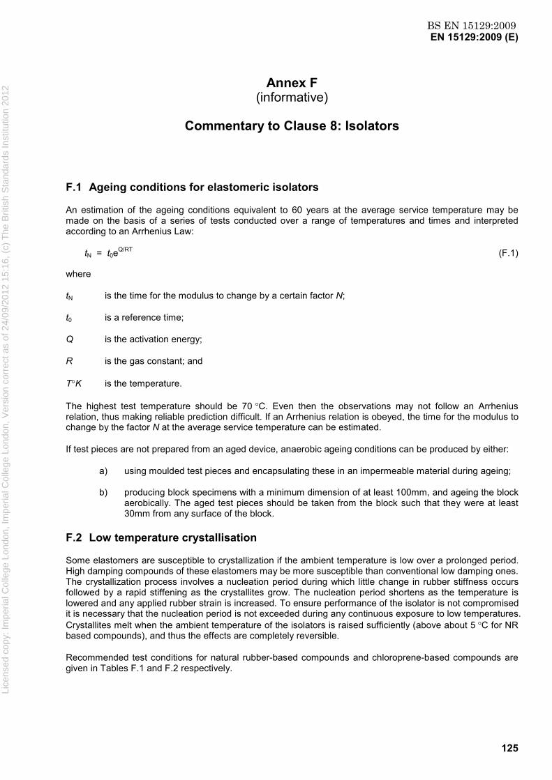
BS EN 15129:2009EN 15129:2009 (E)
125
Annex F (informative)
Commentary to Clause 8: Isolators
F.1 Ageing conditions for elastomeric isolators
An estimation of the ageing conditions equivalent to 60 years at the average service temperature may be made on the basis of a series of tests conducted over a range of temperatures and times and interpreted according to an Arrhenius Law:
tN = t0eQ/RT (F.1)
where
tN is the time for the modulus to change by a certain factor N;
t0 is a reference time;
Q is the activation energy;
R is the gas constant; and
T°K is the temperature.
The highest test temperature should be 70 °C. Even then the observations may not follow an Arrhenius relation, thus making reliable prediction difficult. If an Arrhenius relation is obeyed, the time for the modulus to change by the factor N at the average service temperature can be estimated.
If test pieces are not prepared from an aged device, anaerobic ageing conditions can be produced by either:
a) using moulded test pieces and encapsulating these in an impermeable material during ageing;
b) producing block specimens with a minimum dimension of at least 100mm, and ageing the block aerobically. The aged test pieces should be taken from the block such that they were at least 30mm from any surface of the block.
F.2 Low temperature crystallisation
Some elastomers are susceptible to crystallization if the ambient temperature is low over a prolonged period. High damping compounds of these elastomers may be more susceptible than conventional low damping ones. The crystallization process involves a nucleation period during which little change in rubber stiffness occurs followed by a rapid stiffening as the crystallites grow. The nucleation period shortens as the temperature is lowered and any applied rubber strain is increased. To ensure performance of the isolator is not compromised it is necessary that the nucleation period is not exceeded during any continuous exposure to low temperatures. Crystallites melt when the ambient temperature of the isolators is raised sufficiently (above about 5 °C for NR based compounds), and thus the effects are completely reversible.
Recommended test conditions for natural rubber-based compounds and chloroprene-based compounds are given in Tables F.1 and F.2 respectively.
Lice
nsed
cop
y: Im
peria
l Col
lege
Lon
don,
Impe
rial C
olle
ge L
ondo
n, V
ersi
on c
orre
ct a
s of
24/
09/2
012
15:1
6, (
c) T
he B
ritis
h S
tand
ards
Inst
itutio
n 20
12

BS EN 15129:2009EN 15129:2009 (E)
126
Table F.1 — Service and test conditions for natural rubber
Minimum service
temperature , TL oC -10≤TL <0 -20≤TL <-10
TL <-20
Time (days) at temperature in above range
t0 t-10 t-20
Test temperature, oC -10 -20
-25
Test period 1,5to 1,5t-10 + 0,1t0
1,5t-20 + 0,5t-10 + 0,05t0
Table F.2 — Service and test conditions for chloroprene rubber
Minimum service
temperature , TL oC 0≤TL <5 -5≤TL <0
TL <-5
Time (days) at temperature in above range
t5 t0 t-5
Test temperature, oC
0 -5
-10
Test period 1,5t5 1,5t0 + 0,5t5
1,5t-5 + 0,5t0 + 0,25t5
F.3 Commentary on Basis of design
F.3.1 Shape Factor
For bearings with a rectangular section:
)(2 batabS
r += (F.2)
where a and b are the lengths of the sides of the steel reinforcing plates. For circular bearings with an unplugged hole of diameter dH :
r
H
tdD
S4
)( ' −= (F.3)
Lice
nsed
cop
y: Im
peria
l Col
lege
Lon
don,
Impe
rial C
olle
ge L
ondo
n, V
ersi
on c
orre
ct a
s of
24/
09/2
012
15:1
6, (
c) T
he B
ritis
h S
tand
ards
Inst
itutio
n 20
12

BS EN 15129:2009EN 15129:2009 (E)
127
F.3.2 Design shear strain due to compression by vertical loads
Equation (13) is given in:
For larger shape factors, S > 8, the use of E´C uncorrected for the effect of bulk compressibility leads to an
even greater underestimation of εc,E. However, correcting for the effect of bulk compressibility results in a more substantial overestimation of εc,E. See ISO 22762-2 Annex I.
Because the shape factor of conventional structural bearings is generally smaller than that of seismic bearings, EN 1337-3:2005 does not consider rubber compressibility in calculating εc,E.
F.3.3 Isolator stiffnesses
F.3.3.1 Vertical stiffness
The reason for selecting the value of G in the formula for the calculation of E´c as the value at 100 % shear
strain amplitude is to simplify the design process by choosing a single value of G in all the different formulae. This value of G is conservative for the calculation of ε
c,Ed because the value of G at the shear strain due only
to compression by vertical loads is higher. This conservatism is offset by the fact that the moduli measured in the dynamic tests of 8.2.2.1.3 are, for a given strain, larger than the quasistatic moduli appropriate to the permanent component of the compressive load.
For devices with large shape factor, as are most of the devices used as seismic isolators, the assumption of incompressible rubber leads to significant overestimation of the compression modulus and vertical stiffness. Rubber compressibility may be taken into account with the simple approach given by:
Thus Ec,, the compression modulus, is given by:
b'cc
111EEE
+= (F.4)
Eb is the bulk modulus of the elastomer. In the absence of measured data, Eb may be taken as 2000MPa. This formula is preferred to the empirical equation (20) in EN 1337-3:2005.
The total vertical stiffness, Kv, of a laminated elastomeric isolator is the sum of the vertical deflections of the individual layers given by:
∑=
ci
i
'
v
Et
AK (F.5)
where Eci is the compression modulus given by Equations (15) and (F.4) for the single rubber layer of
thickness ti.
F.3.3.2 Horizontal stiffness
The theoretical value of the horizontal stiffness is given by:
qTGAK =b (F.6)
where Lice
nsed
cop
y: Im
peria
l Col
lege
Lon
don,
Impe
rial C
olle
ge L
ondo
n, V
ersi
on c
orre
ct a
s of
24/
09/2
012
15:1
6, (
c) T
he B
ritis
h S
tand
ards
Inst
itutio
n 20
12
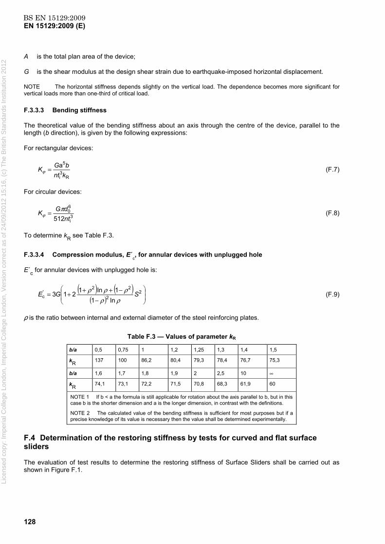
BS EN 15129:2009EN 15129:2009 (E)
128
A is the total plan area of the device;
G is the shear modulus at the design shear strain due to earthquake-imposed horizontal displacement.
NOTE The horizontal stiffness depends slightly on the vertical load. The dependence becomes more significant for vertical loads more than one-third of critical load.
F.3.3.3 Bending stiffness
The theoretical value of the bending stiffness about an axis through the centre of the device, parallel to the length (b direction), is given by the following expressions:
For rectangular devices:
R3i
5akntbGK =ϕ (F.7)
For circular devices:
3i
60
512ntdGK π
ϕ = (F.8)
To determine kR see Table F.3.
F.3.3.4 Compression modulus, E´c, for annular devices with unplugged hole
E´c for annular devices with unplugged hole is:
( ) ( )( )
−−+++= 2
2
22'c
ln11ln1213 SGEρρ
ρρρ (F.9)
ρ is the ratio between internal and external diameter of the steel reinforcing plates.
Table F.3 — Values of parameter kR
b/a 0,5 0,75 1 1,2 1,25 1,3 1,4 1,5
kR 137 100 86,2 80,4 79,3 78,4 76,7 75,3
b/a 1,6 1,7 1,8 1,9 2 2,5 10 ∞
kR 74,1 73,1 72,2 71,5 70,8 68,3 61,9 60
NOTE 1 If b < a the formula is still applicable for rotation about the axis parallel to b, but in this case b is the shorter dimension and a is the longer dimension, in contrast with the definitions.
NOTE 2 The calculated value of the bending stiffness is sufficient for most purposes but if a precise knowledge of its value is necessary then the value shall be determined experimentally.
F.4 Determination of the restoring stiffness by tests for curved and flat surface sliders
The evaluation of test results to determine the restoring stiffness of Surface Sliders shall be carried out as shown in Figure F.1.
Lice
nsed
cop
y: Im
peria
l Col
lege
Lon
don,
Impe
rial C
olle
ge L
ondo
n, V
ersi
on c
orre
ct a
s of
24/
09/2
012
15:1
6, (
c) T
he B
ritis
h S
tand
ards
Inst
itutio
n 20
12
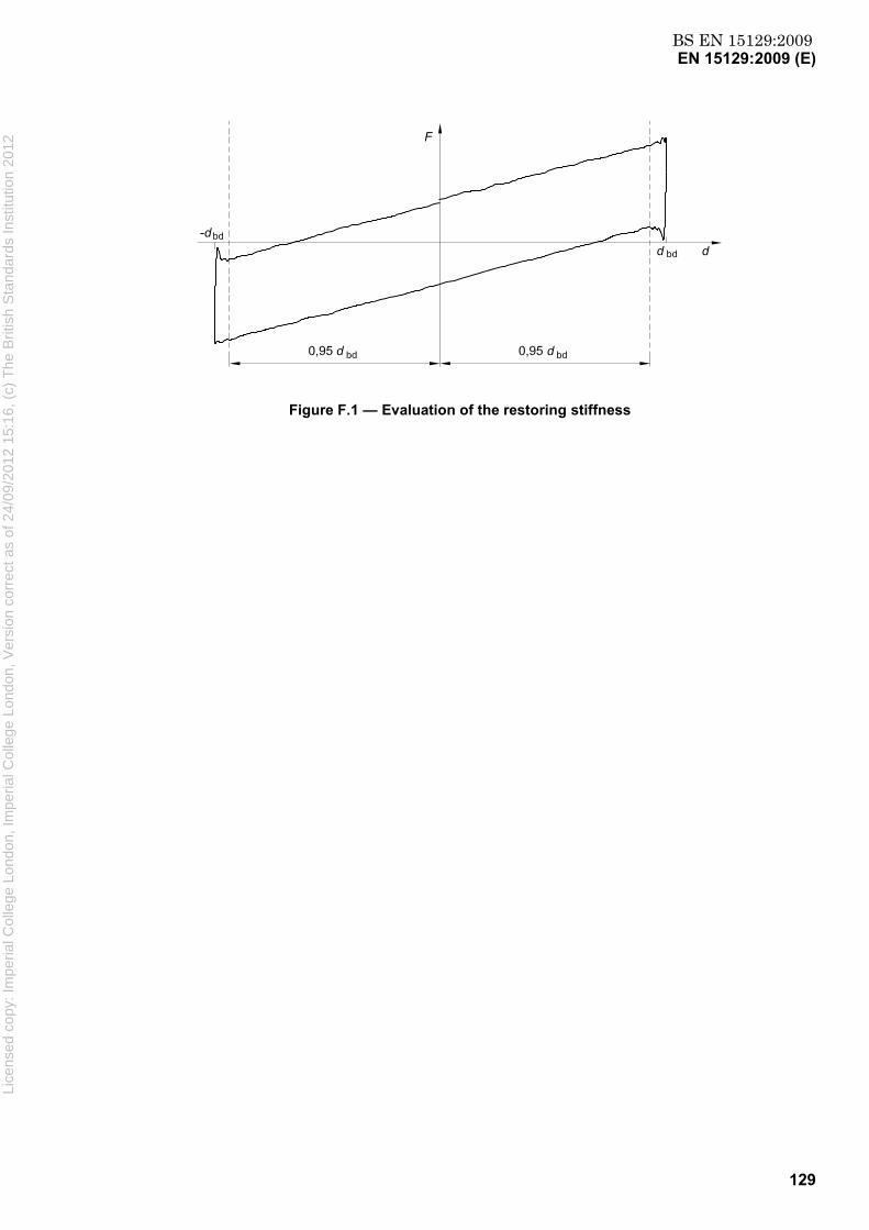
BS EN 15129:2009EN 15129:2009 (E)
129
Figure F.1 — Evaluation of the restoring stiffness
Lice
nsed
cop
y: Im
peria
l Col
lege
Lon
don,
Impe
rial C
olle
ge L
ondo
n, V
ersi
on c
orre
ct a
s of
24/
09/2
012
15:1
6, (
c) T
he B
ritis
h S
tand
ards
Inst
itutio
n 20
12
BS EN 15129:2009EN 15129:2009 (E)
130
Annex G (normative)
Equipment for combined compression and shear
G.1 General requirements
The transducer outputs shall be calibrated and shall be accurate to ± 2 % of the peak output being measured in a particular test. The transducers, amplifiers and recording equipment shall be capable of responding at the test frequency without any significant attenuation. The test report shall include evidence of transducer calibration and evidence of any checks (e.g. regarding the effect of friction in load train) required.
When specified, the exact order of tests and the interval between tests shall be strictly adhered to. The instructions regarding the use of an isolator for more than one test shall also be strictly adhered to.
NOTE These controls are necessary because of strain history effects in the rubber.
G.2 Data Acquisition
Analog or digital data acquisition may be employed. Data shall be digitised or sampled at a rate at least equal to 100 times the frequency of loading. A digital acquisition system shall sample all data channels so that the maximum time skew between channels is less than 1 % of the sampling interval.
G.3 Combined compression and shear equipment
The compressive displacement shall be measured directly between the load platens of the machine. It shall be the average obtained from at least three transducers spaced evenly around the isolator.
If there is any source of friction in the compressive load train, the effect on the compressive load measured shall be < 3 %.
The shear displacement shall be the average of that measured at two points on opposite sides of the isolator(s), along a line orthogonal to the shear loading direction. The shear displacement attained shall be within ± 5 % of that specified. The equipment shall be capable of applying a sinusoidal or triangular displacement of the specified amplitude at the test frequency.
The shear load should be measured in the case of a single isolator configuration by a transducer between the isolator and the reaction support. For whatever test configuration, if a transducer located in the force train of the actuator is to be used, the magnitude of any frictional effects on the force shall be reported and correction made. The shear load train shall be capable of accommodating both the compressive displacement of the isolator(s) and, if tests are conducted under compressive force control rather than displacement control, the change in height of the isolator(s) during their shear deformation. The lateral load plane shall remain within ± 0,08 rad of the bottom and top reaction support plane.
The shear load and displacement shall be continuously recorded.
The vertical load should be applied under load control. It should be maintained constant such that:
(i) average load is within ± 10 % of specified load;
(ii) maximum and minimum loads during test are within ± 10 % of average applied;
Lice
nsed
cop
y: Im
peria
l Col
lege
Lon
don,
Impe
rial C
olle
ge L
ondo
n, V
ersi
on c
orre
ct a
s of
24/
09/2
012
15:1
6, (
c) T
he B
ritis
h S
tand
ards
Inst
itutio
n 20
12

BS EN 15129:2009EN 15129:2009 (E)
131
(iii) area of any hysteresis loops observed in the compressive load train is less than 5 % of the shear force-displacement hysteresis loop;
(iv) any source of friction between the compressive load cell and the isolator(s) contributes energy losses < 5 % of the shear force-displacement hysteresis loops.
If any of the four conditions cannot be met, the compressive load during the tests may be under displacement control, such that, after applying the specified vertical load, the isolator(s) are held at that displacement during the shear deformation. Displacement control of the compressive load may also be used if the shear load train cannot accommodate the change in height of the isolator(s) during shear. Notwithstanding the above, the test of lateral displacement capacity shall be performed with the compressive load held constant under load control. Displacement control of the compressive load shall not be used with curved surface sliders.
The compressive load and displacement (as well as the shear load and displacement) shall be recorded to enable a check to be made that the conditions applicable to the former are satisfied.
G.4 Load Platens
The isolators shall be attached to the load platens with the type of system to be used for the installed isolators.
The platens shall be larger in plan area than the isolators and thick enough to prevent significant distortion (< 2 % of the isolator compressive displacement at the maximum load).
The angle between the upper and lower platen shall be less than 0,003 rad.
The floating platen(s) shall be such that they do not:
(i) rotate about a vertical axis by more than 0,08 rad;
(ii) move orthogonally to the loading directions by more than 10 % of the shear displacement.
G.5 Data analysis
The dynamic horizontal force-displacement data shall be analysable cycle by cycle. The method of analysis shall express the stiffness as:
ddFFK −
−
- - = +
+
b (G.1)
where F and d are the horizontal force and displacement respectively. d+ and d - are the maximum and minimum values of displacement in the cycle, and F+ and F- are the values of force at those displacements. The equivalent viscous damping ratio ξ, shall be expressed as:
)( 2 = 2
b−+ −π
ξddK
H (G.2)
where H is the area of the hysteresis loop.
For LRB the horizontal characteristics may be determined as the second branch (or post-yield) stiffness, K2, and characteristic strength, Qd, see Figure G.1. The value of Qd shall be taken as the average value of the intercepts on the force axis. The stiffness, K2, shall be taken as:
Lice
nsed
cop
y: Im
peria
l Col
lege
Lon
don,
Impe
rial C
olle
ge L
ondo
n, V
ersi
on c
orre
ct a
s of
24/
09/2
012
15:1
6, (
c) T
he B
ritis
h S
tand
ards
Inst
itutio
n 20
12
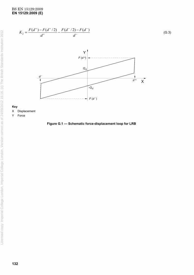
BS EN 15129:2009EN 15129:2009 (E)
132
−
−−
+
++ −−−=d
dFdFd
dFdFK )()2/()2/()(2 (G.3)
Key X Displacement Y Force
Figure G.1 — Schematic force-displacement loop for LRB
Lice
nsed
cop
y: Im
peria
l Col
lege
Lon
don,
Impe
rial C
olle
ge L
ondo
n, V
ersi
on c
orre
ct a
s of
24/
09/2
012
15:1
6, (
c) T
he B
ritis
h S
tand
ards
Inst
itutio
n 20
12

BS EN 15129:2009EN 15129:2009 (E)
133
Annex H (informative)
Design of Connections for Devices
H.1 Elastomeric Isolators
The connections between the isolator and the bearing plate fixed to the structure are designed to withstand a force equal to γRd FUB , where FUB corresponds to the force at γb (dEd )UB; (dEd )UB is the maximum displacement calculated using the upper values of the device design properties (see Figure H.1). γRd is an overstrength factor for elastomeric isolators; the recommended value of γRd is 1,1.
Key 1 Upper Bound 2 Nominal Curve 3 Lower Bound
Figure H.1 — Schematic diagram indicating determination of FUB for elastomeric isolators
H.2 Sliders
The connections between the slider and the plate fixed to the structure shall be designed to withstand a force equal to γRd FUB , where FUB corresponds to the force at γb (dEd )UB; (dEd )UB is the maximum displacement calculated using the upper values of the device design properties (see Figure H.2 for an example of a slider with approximately linear characteristics). γRd is an overstrength factor for curved surface sliders. The recommended value of γRd is 1,1.
Lice
nsed
cop
y: Im
peria
l Col
lege
Lon
don,
Impe
rial C
olle
ge L
ondo
n, V
ersi
on c
orre
ct a
s of
24/
09/2
012
15:1
6, (
c) T
he B
ritis
h S
tand
ards
Inst
itutio
n 20
12
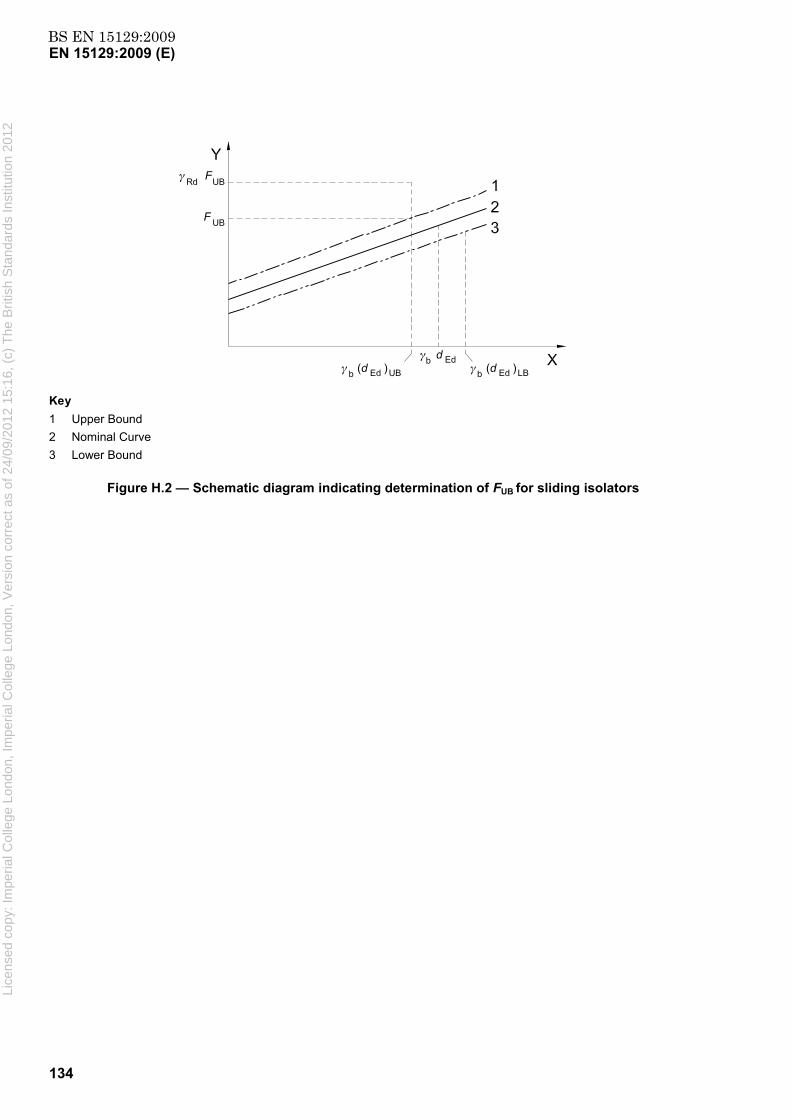
BS EN 15129:2009EN 15129:2009 (E)
134
Key 1 Upper Bound 2 Nominal Curve 3 Lower Bound
Figure H.2 — Schematic diagram indicating determination of FUB for sliding isolators
Lice
nsed
cop
y: Im
peria
l Col
lege
Lon
don,
Impe
rial C
olle
ge L
ondo
n, V
ersi
on c
orre
ct a
s of
24/
09/2
012
15:1
6, (
c) T
he B
ritis
h S
tand
ards
Inst
itutio
n 20
12

BS EN 15129:2009EN 15129:2009 (E)
135
Annex I (informative)
Method for calculating pressure distributions on spherical surfaces
I.1 General
This annex describes a method for calculating pressure distributions in the bearing sliding material of spherical surfaces used in Curved Surface Sliders. Also, this method allows to conduct the verification of separation of sliding surfaces.
Even though the procedure is analytically rigorous, results are nonetheless physically not exact, due to the simplifying nature of some of the assumptions made regarding the behaviour of the materials. However, the results are conservative and accurate enough for the purpose of this annex.
I.2 Modelling assumptions
a) Both concave and convex backing plates are perfectly rigid; a conservative hypothesis justified by the fact that steel's elastic modulus is at least 5 000 times greater than that of bearing sliding material.
b) Stresses are always normal to the contact surface; a conservative hypothesis justified by the relatively low coefficient of friction of sliding surfaces.
c) There are no sliding movements between bearing sliding material and backing plate; this hypothesis is true only in the case of bonded bearing sliding material, but can also be assumed as valid for confined sliding material.
d) The reaction is proportional to the deformation at each point in the sliding material sheet; this is the so called “Winkler's soils hypothesis” - which is conservative, since it considers negligible the effect of containment of the adjacent elements, i.e. it assumes a Poisson's ratio ν = 0.
I.3 Effects of vertical loads
The equations make reference to the symbols shown in Figure I.1.
Under the above hypothesis, when a vertical load Fz is applied to the convex element, the pressure distribution σ (θ) on the bearing sliding material, as a function of the angle θ, is given by:
σ (θ) = ( )δπθ
32 cos1cos
23
−⋅ rFZ (I.1)
which presents a maximum for θ = 0 :
σmax = ( )δπ 32 cos123
−⋅ rFZ = σ ( )δ
δ3
2
cos12sin3−
(I.2)
where σ is the average pressure, defined as the ratio between the vertical load Fz and the area A = π·L2/4 of the spherical surface projection on the horizontal plane normal to its symmetry axis. Li
cens
ed c
opy:
Impe
rial C
olle
ge L
ondo
n, Im
peria
l Col
lege
Lon
don,
Ver
sion
cor
rect
as
of 2
4/09
/201
2 15
:16,
(c)
The
Brit
ish
Sta
ndar
ds In
stitu
tion
2012

BS EN 15129:2009EN 15129:2009 (E)
136
Values of the function:
f(δ) = δ
δ3
2
cos1sin
23
− (I.3)
Figure I.1 — Sketch of the spherical surface
that represents the deviation of the maximum pressure - as a function of the half included angle δ of the sliding material spherical surface - with respect to the case of a plane surface are given in Table I.1.
Table I.1 — Values of the function f (δ)
δ f(δ)
δ f(δ)
10°
15°
20°
25°
1,008
1,017
1,031
1,048
30°
35°
40°
45°
1,070
1,096
1,126
1,160
The maximum (peak) pressure on a spherical surface does not significantly differ from that of the equivalent plane surface.
Similarly, the values of the deviation of the edge pressure on a spherical surface (θ = δ) with respect to the case of a plane surface are given Table I.2. Li
cens
ed c
opy:
Impe
rial C
olle
ge L
ondo
n, Im
peria
l Col
lege
Lon
don,
Ver
sion
cor
rect
as
of 2
4/09
/201
2 15
:16,
(c)
The
Brit
ish
Sta
ndar
ds In
stitu
tion
2012
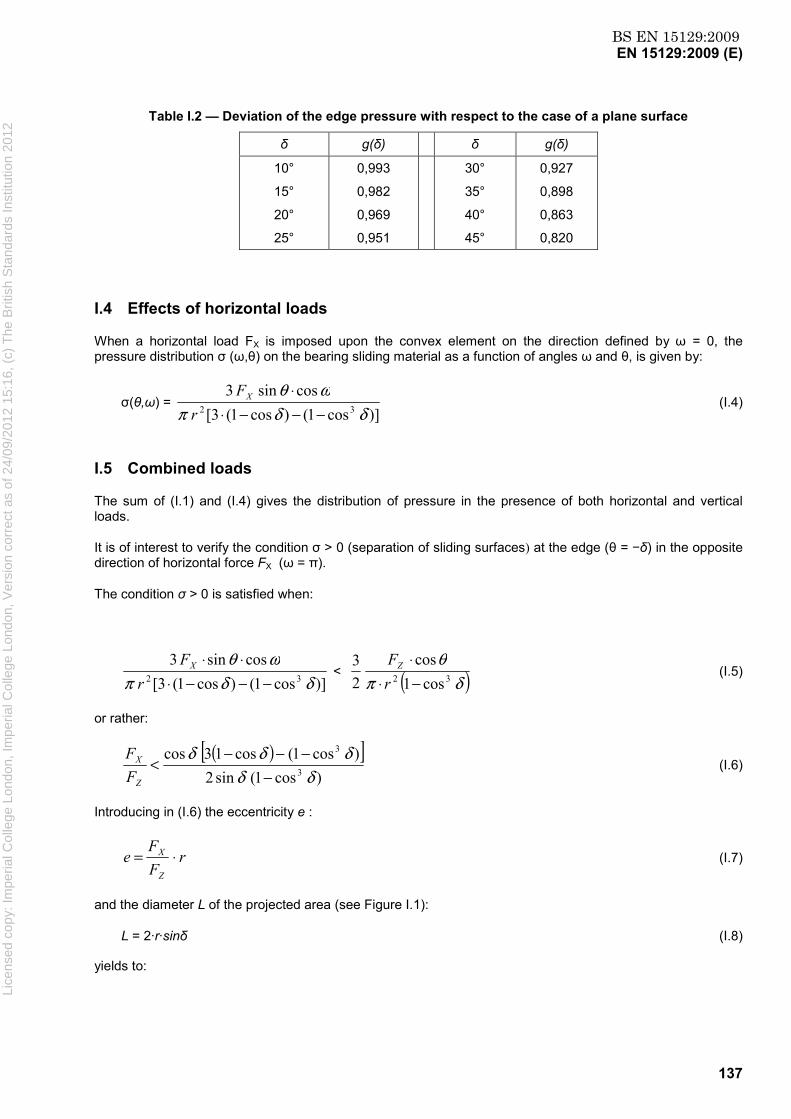
BS EN 15129:2009EN 15129:2009 (E)
137
Table I.2 — Deviation of the edge pressure with respect to the case of a plane surface
δ g(δ)
δ g(δ)
10°
15°
20°
25°
0,993
0,982
0,969
0,951
30°
35°
40°
45°
0,927
0,898
0,863
0,820
I.4 Effects of horizontal loads
When a horizontal load FX is imposed upon the convex element on the direction defined by ω = 0, the pressure distribution σ (ω,θ) on the bearing sliding material as a function of angles ω and θ, is given by:
σ(θ,ω) = )]cos1()cos1(3[
cossin332 δδπ
ωθ−−−⋅
⋅r
FX (I.4)
I.5 Combined loads
The sum of (I.1) and (I.4) gives the distribution of pressure in the presence of both horizontal and vertical loads.
It is of interest to verify the condition σ > 0 (separation of sliding surfaces) at the edge (θ = −δ) in the opposite direction of horizontal force FX (ω = π).
The condition σ > 0 is satisfied when:
)]cos1()cos1(3[cossin3
32 δδπωθ
−−−⋅⋅⋅
rFX < ( )δπ
θ32 cos1
cos23
−⋅⋅
rFZ (I.5)
or rather:
( )[ ])cos1(sin2
)cos1(cos13cos3
3
δδδδδ
−−−−
<Z
X
FF
(I.6)
Introducing in (I.6) the eccentricity e :
rFF
eZ
X ⋅= (I.7)
and the diameter L of the projected area (see Figure I.1):
L = 2·r·sinδ (I.8)
yields to:
Lice
nsed
cop
y: Im
peria
l Col
lege
Lon
don,
Impe
rial C
olle
ge L
ondo
n, V
ersi
on c
orre
ct a
s of
24/
09/2
012
15:1
6, (
c) T
he B
ritis
h S
tand
ards
Inst
itutio
n 20
12
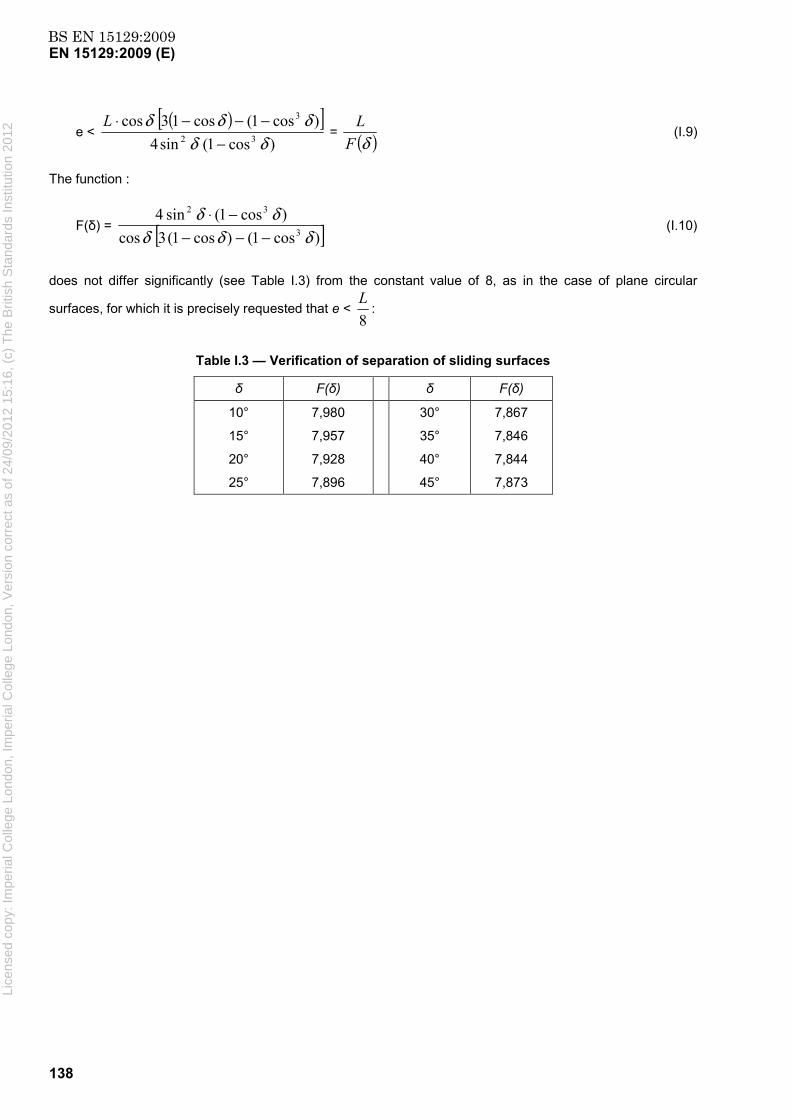
BS EN 15129:2009EN 15129:2009 (E)
138
e <( )[ ]
)cos1(sin4)cos1(cos13cos
32
3
δδδδδ
−−−−⋅L
= ( )δFL
(I.9)
The function :
F(δ) = [ ])cos1()cos1(3cos)cos1(sin4
3
32
δδδδδ
−−−−⋅
(I.10)
does not differ significantly (see Table I.3) from the constant value of 8, as in the case of plane circular
surfaces, for which it is precisely requested that e < 8L
:
Table I.3 — Verification of separation of sliding surfaces
δ F(δ)
δ F(δ)
10°
15°
20°
25°
7,980
7,957
7,928
7,896
30°
35°
40°
45°
7,867
7,846
7,844
7,873
Lice
nsed
cop
y: Im
peria
l Col
lege
Lon
don,
Impe
rial C
olle
ge L
ondo
n, V
ersi
on c
orre
ct a
s of
24/
09/2
012
15:1
6, (
c) T
he B
ritis
h S
tand
ards
Inst
itutio
n 20
12

BS EN 15129:2009EN 15129:2009 (E)
139
Annex J (informative)
λλλλ-FACTORS FOR COMMON ISOLATOR TYPES
J.1 λmax- values for elastomeric isolators
Unless different values are substantiated by appropriate tests, the λmax-values specified in Tables J.1 to J.4 may be used for estimation of the UBDP.
Table J.1 — f1 – Ageing
Component λmax, f1 for Kp Fo
LDRB 1,1 1,1
HDRB1 1,2 1,2
HDRB2 1,3 1,3
Lead core - 1,0
with the following designations for the rubber components:
LDRB: Low damping rubber bearing with shear modulus, at shear deformation of 100 %, larger than 0,5 MPa
HDRB1: High damping rubber bearing with ξeff ≤ 0,15 and shear modulus, at shear deformation of 100 %, larger than 0,5 MPa
HDRB2: High damping rubber bearing with ξeff > 0,15 and shear modulus, at shear deformation of 100 %, larger than 0,5 MPa
Lead core: Lead core for Lead rubber bearings (LRB)
Table J.2 — f2 – Temperature
Design Temperature
Tmin,b (oC)
λmax, f2 for Kp Fo
LDRB HDRB1 HDRB2 LDRB HDRB1 HDRB2 20 1,0 1,0 1,0 1,0 1,0 1,0 0 1,3 1,3 1,3 1,1 1,1 1,2
-10 1,4 1,4 1,4 1,1 1,2 1,4 -30 1,5 2,0 2,5 1,3 1,4 2,0
Tmin,b is the minimum isolator temperature for the seismic design situation, corresponding to the bridge location (see EN 1998-2:2005, Annex J, J.1, (2)).
Table J.3 — f3 - Contamination
λmax,f3 = 1,0
Lice
nsed
cop
y: Im
peria
l Col
lege
Lon
don,
Impe
rial C
olle
ge L
ondo
n, V
ersi
on c
orre
ct a
s of
24/
09/2
012
15:1
6, (
c) T
he B
ritis
h S
tand
ards
Inst
itutio
n 20
12

BS EN 15129:2009EN 15129:2009 (E)
140
Table J.4 — f4 – Cumulative travel
Rubber λmax,f4 = 1,0 Lead core To be established by test
J.2 λmax- values for sliding isolator units
Unless different values are substantiated by appropriate test results, the λmax- values specified in the following Tables J.5 to J.8 may be used for the estimation of the maximum force at zero displacement Fo corresponding to the UBDP. The values given for unlubricated PTFE may be taken to apply also for Curved Surface Sliders.
Table J.5 — f1 – Ageing
λmax,f1 Component Unlubricated
PTFE Lubricated
PTFE Bimetallic Interfaces
Environment Sealed Unsealed Sealed Unsealed Sealed Unsealed Normal 1,1 1,2 1,3 1,4 2,0 2,2 Severe 1,2 1,5 1,4 1,8 2,2 2,5
The values in Table J.5 refer to the following conditions:
Stainless steel sliding plates are assumed
Unsealed conditions are assumed, to allow exposure of the sliding surfaces to water and salt
Severe environment includes marine and industrial conditions
Values for bimetallic interfaces apply to stainless steel and bronze interfaces.
Table J.6 — f2 – Temperature
Design Temperature λmax,f2
Tmin,b (° C) Unlubricated PTFE
Lubricated PTFE
Bimetallic Interfaces
20 1,0 1,0 To be established
by test
0 1,1 1,3 -10 1,2 1,5 -30 1,5 3,0
Table J.7 — f3 – Contamination
λmax,f3 Installation Unlubricated
PTFE Lubricated
PTFE Bimetallic Interfaces
Sealed, with stainless steel surface facing
down 1,0 1,0 1,0
Sealed, with stainless steel surface facing up 1,1 1,1 1,1
Unsealed, with stainless steel surface facing
down 1,2 3,0 1,1
The values in Table J.7 refer to the following conditions:
Lice
nsed
cop
y: Im
peria
l Col
lege
Lon
don,
Impe
rial C
olle
ge L
ondo
n, V
ersi
on c
orre
ct a
s of
24/
09/2
012
15:1
6, (
c) T
he B
ritis
h S
tand
ards
Inst
itutio
n 20
12

BS EN 15129:2009EN 15129:2009 (E)
141
Sealing of bearings is assumed to offer contamination protection under all serviceability conditions
Table J.8 — f4 – Cumulative travel
λmax, f4 Cumulative Travel (km)
Unlubricated PTFE
Lubricated PTFE
Bimetallic Interfaces
≤ 1,0 1,0 1,0 To be
established by test
1,0 < and ≤ 2,0 1,2 1,0 To be
established by test
Lice
nsed
cop
y: Im
peria
l Col
lege
Lon
don,
Impe
rial C
olle
ge L
ondo
n, V
ersi
on c
orre
ct a
s of
24/
09/2
012
15:1
6, (
c) T
he B
ritis
h S
tand
ards
Inst
itutio
n 20
12

BS EN 15129:2009EN 15129:2009 (E)
142
Annex ZA (informative)
Relationship between this European Standard and the Essential
Requirements of EU Directive
ZA.1 Scope and relevant characteristics
This European Standard has been prepared under Mandate M/104 Structural bearings as amended by M/132 given to CEN by the European Commission and the European Free Trade Association.
The clauses of this European Standard shown in this annex meet the requirements of the mandate given under the EU Construction Products Directive (89/106/EEC).
Compliance with these clauses confers a presumption of fitness of the anti-seismic devices covered by this annex for the intended uses indicated herein; reference shall be made to the information accompanying the CE marking.
WARNING — Other requirements and other EU Directives, not affecting the fitness for intended uses, can be applicable to the anti-seismic devices falling within the scope of this European Standard.
NOTE 1 In addition to any specific clauses relating to dangerous substances contained in this standard, there may be other requirements applicable to the products falling within its scope (e.g. transposed European legislation and national laws, regulations and administrative provisions). In order to meet the provisions of the EU Construction Products Directive, these requirements need also to be complied with, when and where they apply.
NOTE 2 An informative database of European and national provisions on dangerous substances available at the Construction web site on EUROPA (accessed through http://europa.eu.int/comm/enterprise/ construction/internal/dangsub/dangmain.htm).
This annex establishes the conditions for the CE marking of the anti-seismic devices intended for the uses indicated in Tables ZA.1.a. to ZA.1.f and shows the relevant clauses applicable:
This annex has the same scope as Clause 1 of this standard and is defined by Tables ZA.1.a. to ZA.1.f.
Lice
nsed
cop
y: Im
peria
l Col
lege
Lon
don,
Impe
rial C
olle
ge L
ondo
n, V
ersi
on c
orre
ct a
s of
24/
09/2
012
15:1
6, (
c) T
he B
ritis
h S
tand
ards
Inst
itutio
n 20
12
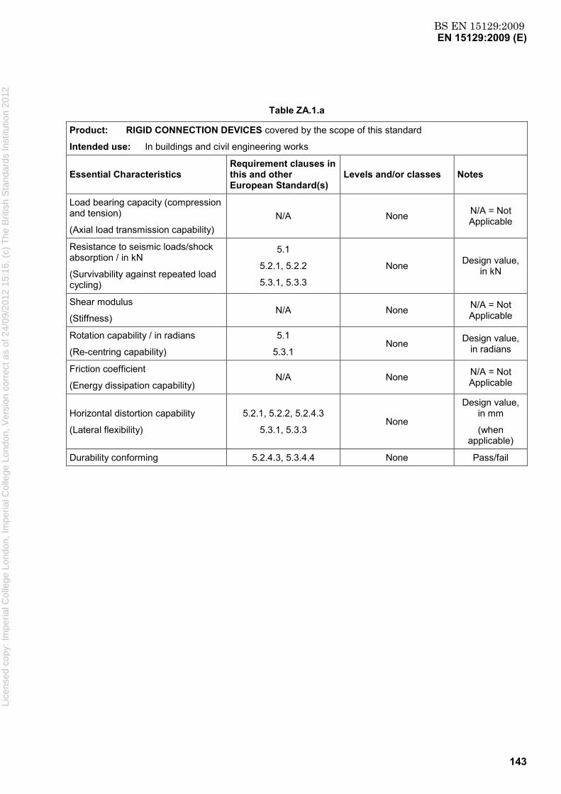
BS EN 15129:2009EN 15129:2009 (E)
143
Table ZA.1.a
Product: RIGID CONNECTION DEVICES covered by the scope of this standard
Intended use: In buildings and civil engineering works
Essential Characteristics Requirement clauses in this and other European Standard(s)
Levels and/or classes Notes
Load bearing capacity (compression and tension)
(Axial load transmission capability) N/A None N/A = Not
Applicable
Resistance to seismic loads/shock absorption / in kN
(Survivability against repeated load cycling)
5.1
5.2.1, 5.2.2
5.3.1, 5.3.3
None Design value, in kN
Shear modulus
(Stiffness) N/A None N/A = Not
Applicable
Rotation capability / in radians
(Re-centring capability)
5.1
5.3.1 None Design value,
in radians
Friction coefficient
(Energy dissipation capability) N/A None N/A = Not
Applicable
Horizontal distortion capability
(Lateral flexibility)
5.2.1, 5.2.2, 5.2.4.3
5.3.1, 5.3.3 None
Design value, in mm
(when applicable)
Durability conforming 5.2.4.3, 5.3.4.4 None Pass/fail
Lice
nsed
cop
y: Im
peria
l Col
lege
Lon
don,
Impe
rial C
olle
ge L
ondo
n, V
ersi
on c
orre
ct a
s of
24/
09/2
012
15:1
6, (
c) T
he B
ritis
h S
tand
ards
Inst
itutio
n 20
12
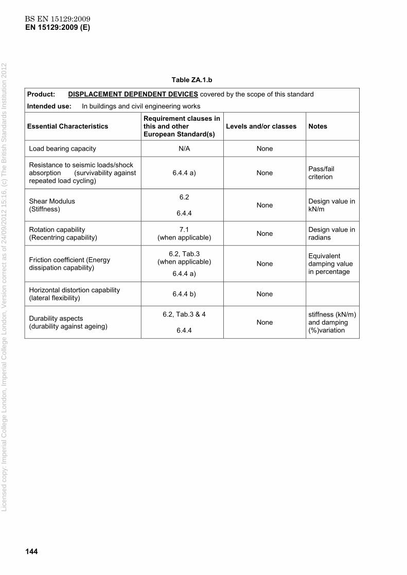
BS EN 15129:2009EN 15129:2009 (E)
144
Table ZA.1.b
Product: DISPLACEMENT DEPENDENT DEVICES covered by the scope of this standard
Intended use: In buildings and civil engineering works
Essential Characteristics Requirement clauses in this and other European Standard(s)
Levels and/or classes Notes
Load bearing capacity N/A None
Resistance to seismic loads/shock absorption (survivability against repeated load cycling)
6.4.4 a) None Pass/fail criterion
Shear Modulus (Stiffness)
6.2
6.4.4 None Design value in
kN/m
Rotation capability (Recentring capability)
7.1 (when applicable) None Design value in
radians
Friction coefficient (Energy dissipation capability)
6.2, Tab.3 (when applicable)
6.4.4 a) None
Equivalent damping value in percentage
Horizontal distortion capability (lateral flexibility) 6.4.4 b) None
Durability aspects (durability against ageing)
6.2, Tab.3 & 4
6.4.4 None
stiffness (kN/m) and damping (%)variation
Lice
nsed
cop
y: Im
peria
l Col
lege
Lon
don,
Impe
rial C
olle
ge L
ondo
n, V
ersi
on c
orre
ct a
s of
24/
09/2
012
15:1
6, (
c) T
he B
ritis
h S
tand
ards
Inst
itutio
n 20
12

BS EN 15129:2009EN 15129:2009 (E)
145
Table ZA.1.c
Product: Velocity Dependent Devices covered by the scope of this standard
Intended Use: In buildings and civil engineering works
Essential Characteristics
Requirement Clauses in this and other European
Standard(s)
Levels and/or classes
Notes
Load Bearing Capacity
(Axial load transmission capability)
7.1, 7.3.1, 7.3.2, 7.3.3 None Pass/Fail Criteria
Resistance to seismic loads / shock absorption
(Survivability against repeated load cycling)
7.1, 7.4.2.5, 7.4.2.6, 7.4.2.8
None Design value in kN
Stiffness
(Lateral flexibility)
7.1, 7.4.2.6 None Design value in kN/mm
(for Fluid Spring Dampers only)
Rotation Capability 7.1 None Information on characteristics
Friction coefficient
(Energy dissipation capability)
7.4.2.7 None Information on characteristics
Horizontal distortion capability
(Stroke)
7.1, 7.4.2.10 None Design value in mm
Durability aspects (durability against ageing, temperature, corrosion)
7.1, 7.4.2.8, 7.4.2.9 None Pass/Fail Criteria
Lice
nsed
cop
y: Im
peria
l Col
lege
Lon
don,
Impe
rial C
olle
ge L
ondo
n, V
ersi
on c
orre
ct a
s of
24/
09/2
012
15:1
6, (
c) T
he B
ritis
h S
tand
ards
Inst
itutio
n 20
12

BS EN 15129:2009EN 15129:2009 (E)
146
Table ZA.1.d
Product: ELASTOMERIC ISOLATORS covered by the scope of this standard
Intended use: In buildings and civil engineering works – For Low Damping Elastomeric Isolators see Table ZA.1.d
Essential Characteristics Requirement clauses in this and other European Standard(s)
Levels and/or classes Notes
Load bearing capacity (compression and tension)
(Axial load transmission capability)
- 8.2.1.2.6
- 8.2.1.2.7
- 8.2.3.4.2
- 8.2.3.4.3
- 8.2.3.4.4/8.2.3.4.5
For bridge isolators only:
- EN 1337-3:2005 4.3.4
None
Pass/fail criteria
Resistance to seismic loads/shock absorption
(Survivability against repeated load cycling)
- 8.2.1.2.5
None
Pass/fail criteria
Shear Stiffness
- 8.2.1.2.2
- 8.2.1.2.3
- 8.2.1.2.4
- 8.2.2.1.5
None
Design value, kN/mm
Pass/fail criteria
Pass/fail criteria
Rotation capability
(Re-centring capability)
- 8.2.3.4.2 None
Pass/fail criteria
Energy dissipation capability
- 8.2.1.2.2
- 8.2.1.2.3
- 8.2.1.2.4
None
Design value, %percent critical damping
Pass/fail criteria
Pass/fail criteria
Horizontal distortion capability
(Lateral flexibility)
- 8.2.1.2.7
- 8.2.2.1.4
- 8.2.3.4.1
- 8.2.3.4.2
None
Pass/fail criteria
Durability aspects
(Durability against ageing)
- 8.2.1.2.9
- 8.2.2.1.3.5
- 8.2.2.1.4.2
- 8.2.2.1.6
For bridge isolators only:
- EN 1337-3:2005 4.3.6
None
Pass/fail criteria
Lice
nsed
cop
y: Im
peria
l Col
lege
Lon
don,
Impe
rial C
olle
ge L
ondo
n, V
ersi
on c
orre
ct a
s of
24/
09/2
012
15:1
6, (
c) T
he B
ritis
h S
tand
ards
Inst
itutio
n 20
12

BS EN 15129:2009EN 15129:2009 (E)
147
Table ZA.1.e
Product: LOW DAMPING ELASTOMERIC ISOLATORS covered by the scope of this standard
Intended use: For bridges subjected to low seismicity – For other application see Table ZA.1.d Elastomeric Isolators
Essential Characteristics Requirement clauses in this and other European Standard(s)
Levels and/or classes Notes
Load bearing capacity (compression and tension)
(Axial load transmission capability)
- 8.2.1.2.7
- 8.2.3.4.2
- 8.2.3.4.3
- 8.2.3.4.4/8.2.3.4.5
- EN 1337-3:2005 4.3.4
None
Pass/fail criteria
Resistance to seismic loads/shock absorption
(Survivability against repeated load cycling)
N/A
N/A = Not Applicable
Shear Stiffness
- 8.2.1.2.2/8.2.1.2.11
- 8.2.1.2.4
- EN 1337-3:2005 4.3.1
None
Design value, kN/mm
Pass/fail criteria
Pass/fail criteria
Rotation capability
(Re-centring capability)
- 8.2.3.4.2 None
Pass/fail criteria
Energy dissipation capability
N/A
N/A = Not Applicable
Horizontal distortion capability
(Lateral flexibility)
- 8.2.1.2.7/8.2.1.2.11
- 8.2.3.4.1
- 8.2.3.4.2
- EN 1337-3:2005 4.3.2
None
Pass/fail criteria
Durability aspects
(Durability against ageing)
- EN 1337-3:2005 4.3.6, 4.4.2
None
Pass/fail criteria
Lice
nsed
cop
y: Im
peria
l Col
lege
Lon
don,
Impe
rial C
olle
ge L
ondo
n, V
ersi
on c
orre
ct a
s of
24/
09/2
012
15:1
6, (
c) T
he B
ritis
h S
tand
ards
Inst
itutio
n 20
12
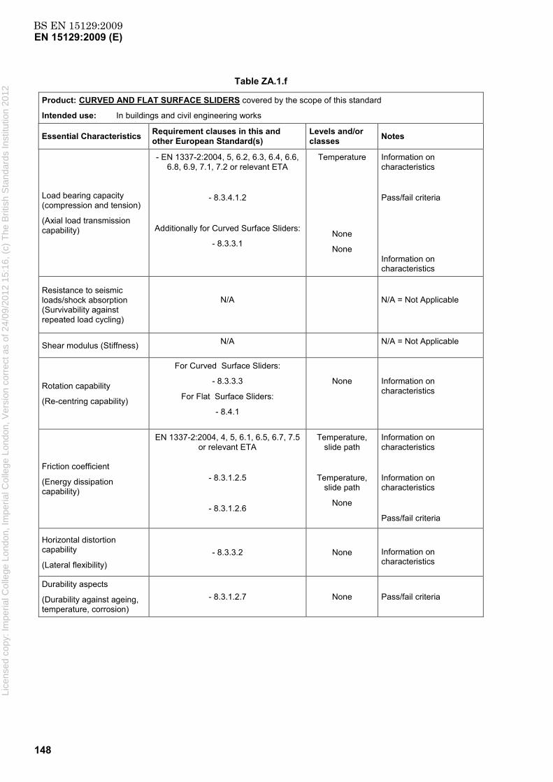
BS EN 15129:2009EN 15129:2009 (E)
148
Table ZA.1.f
Product: CURVED AND FLAT SURFACE SLIDERS covered by the scope of this standard
Intended use: In buildings and civil engineering works
Essential Characteristics Requirement clauses in this and other European Standard(s)
Levels and/or classes Notes
Load bearing capacity (compression and tension)
(Axial load transmission capability)
- EN 1337-2:2004, 5, 6.2, 6.3, 6.4, 6.6, 6.8, 6.9, 7.1, 7.2 or relevant ETA
- 8.3.4.1.2
Additionally for Curved Surface Sliders:
- 8.3.3.1
Temperature
None
None
Information on characteristics
Pass/fail criteria
Information on characteristics
Resistance to seismic loads/shock absorption (Survivability against repeated load cycling)
N/A
N/A = Not Applicable
Shear modulus (Stiffness) N/A N/A = Not Applicable
Rotation capability
(Re-centring capability)
For Curved Surface Sliders:
- 8.3.3.3
For Flat Surface Sliders:
- 8.4.1
None
Information on characteristics
Friction coefficient
(Energy dissipation capability)
EN 1337-2:2004, 4, 5, 6.1, 6.5, 6.7, 7.5 or relevant ETA
- 8.3.1.2.5
- 8.3.1.2.6
Temperature, slide path
Temperature, slide path
None
Information on characteristics
Information on characteristics
Pass/fail criteria
Horizontal distortion capability
(Lateral flexibility) - 8.3.3.2 None
Information on characteristics
Durability aspects
(Durability against ageing, temperature, corrosion)
- 8.3.1.2.7 None Pass/fail criteria
Lice
nsed
cop
y: Im
peria
l Col
lege
Lon
don,
Impe
rial C
olle
ge L
ondo
n, V
ersi
on c
orre
ct a
s of
24/
09/2
012
15:1
6, (
c) T
he B
ritis
h S
tand
ards
Inst
itutio
n 20
12

BS EN 15129:2009EN 15129:2009 (E)
149
The requirement on a certain characteristic is not applicable in those Member States (MSs) where there are no regulatory requirements on that characteristic for the intended use of the product. In this case, manufacturers placing their products on the market of these MSs are not obliged to determine nor declare the performance of their products with regard to this characteristic and the option “No performance determined” (NPD) in the information accompanying the CE marking (see ZA.3) may be used. The NPD option may not be used, however, where the characteristic is subject to a threshold level.
ZA.2 Procedure(s) for attestation of conformity of anti-seismic devices
ZA.2.1 System(s) of attestation of conformity
The system(s) of attestation of conformity of anti-seismic devices indicated in Tables ZA.1.a to ZA.1.f, in accordance with the Decision of the Commission 95/467/EC of 1995-10-24 as amended by the decisions 01/596/EC of 8 January 2001 (published as document L209 the 02.08.01)and 2002/592/EC of 15 July 2002 (published as L192 the 20.07.02) and as given in Annex III of the mandate for "Structural bearings", is shown in Table ZA.2 for the indicated intended use(s) and relevant level(s) or class(es):
Table ZA.2 — System (s) of attestation of conformity
Product(s) Intended use(s) Level(s) or class(es)
Attestation of conformity system(s)
Anti-seismic devices
In buildings and civil engineering works where requirements on individual devices are critical a
None
1
In buildings and civil engineering works where requirements on individual devices are not critical b
3
System 1: See Directive 89/106/EEC (CPD) Annex III.2.(i), without audit testing of samples.
System 3: See Directive 89/106/EEC (CPD) Annex III.2.(ii), Second possibility. a Critical in the sense that those requirements may, in case of failure of the device, put the works or parts thereof in states beyond those regarded as serviceability and ultimate limit states. b Not critical in the sense that those requirements may not, in case of failure of the device and under normal circumstances, put the works or parts thereof in states beyond those regarded as serviceability and ultimate limit states.
The attestation of conformity of the anti-seismic devices in Tables ZA.1.a to ZA.1.f shall be based on the evaluation of conformity procedures indicated in Tables ZA.3.a and ZA.3.b resulting from application of the clauses of this or other European Standard indicated therein.
Lice
nsed
cop
y: Im
peria
l Col
lege
Lon
don,
Impe
rial C
olle
ge L
ondo
n, V
ersi
on c
orre
ct a
s of
24/
09/2
012
15:1
6, (
c) T
he B
ritis
h S
tand
ards
Inst
itutio
n 20
12
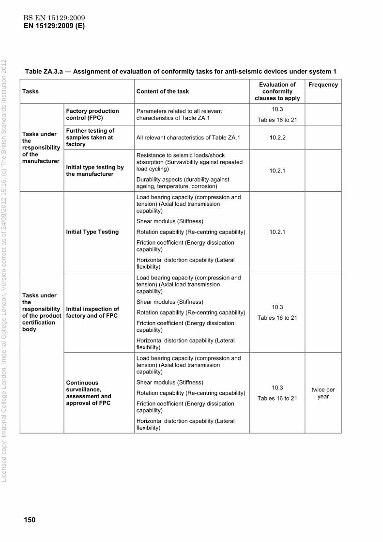
BS EN 15129:2009EN 15129:2009 (E)
150
Table ZA.3.a — Assignment of evaluation of conformity tasks for anti-seismic devices under system 1
Tasks Content of the task Evaluation of
conformity clauses to apply
Frequency
Tasks under the responsibility of the manufacturer
Factory production control (FPC)
Parameters related to all relevant characteristics of Table ZA.1
10.3
Tables 16 to 21
Further testing of samples taken at factory
All relevant characteristics of Table ZA.1 10.2.2
Initial type testing by the manufacturer
Resistance to seismic loads/shock absorption (Survavibility against repeated load cycling)
Durability aspects (durability against ageing, temperature, corrosion)
10.2.1
Tasks under the responsibility of the product certification body
Initial Type Testing
Load bearing capacity (compression and tension) (Axial load transmission capability)
Shear modulus (Stiffness)
Rotation capability (Re-centring capability)
Friction coefficient (Energy dissipation capability)
Horizontal distortion capability (Lateral flexibility)
10.2.1
Initial inspection of factory and of FPC
Load bearing capacity (compression and tension) (Axial load transmission capability)
Shear modulus (Stiffness)
Rotation capability (Re-centring capability)
Friction coefficient (Energy dissipation capability)
Horizontal distortion capability (Lateral flexibility)
10.3
Tables 16 to 21
Continuous surveillance, assessment and approval of FPC
Load bearing capacity (compression and tension) (Axial load transmission capability)
Shear modulus (Stiffness)
Rotation capability (Re-centring capability)
Friction coefficient (Energy dissipation capability)
Horizontal distortion capability (Lateral flexibility)
10.3
Tables 16 to 21 twice per
year
Lice
nsed
cop
y: Im
peria
l Col
lege
Lon
don,
Impe
rial C
olle
ge L
ondo
n, V
ersi
on c
orre
ct a
s of
24/
09/2
012
15:1
6, (
c) T
he B
ritis
h S
tand
ards
Inst
itutio
n 20
12

BS EN 15129:2009EN 15129:2009 (E)
151
Table ZA.3.b — Assignment of evaluation of conformity tasks for anti-seismic devices under system 3
Tasks Content of the task Evaluation of conformity clauses to apply
Tasks under the responsibility of the manufacturer
Factory production control (FPC)
Parameters related to all relevant characteristics of Table ZA.1
10.3
Tables 16 to 21
Initial Type Testing by the manufacturer
Resistance to seismic loads/shock absorption (Survavibility against repeated load cycling)
Durability aspects (durability against ageing, temperature, corrosion)
10.2.1
Initial Type Testing by a notified test laboratory
Load bearing capacity (compression and tension) (Axial load transmission capability)
Shear modulus (Stiffness)
Rotation capability (Re-centring capability)
Friction coefficient (Energy dissipation capability)
Horizontal distortion capability (Lateral flexibility)
10.2.1
ZA.2.2 EC Certificate and Declaration of conformity
(In case of products with system 1):
When compliance with the conditions of this annex is achieved, the certification body shall draw up a certificate of conformity (EC Certificate of conformity), which entitles the manufacturer to affix the CE marking. The certificate shall include:
name, address and identification number of the certification body,
name and address of the manufacturer, or his authorised representative established in the EEA, and place of production.
NOTE 1 The manufacturer may also be the person responsible for placing the product onto the EEA market, if he takes responsibility for CE marking.
description of the product (type, identification, use, ...),
provisions to which the product conforms (i.e. Annex ZA of this EN),
particular conditions applicable to the use of the product (e.g. provisions for use under certain conditions),
the number of the certificate,
conditions of validity of the certificate, where applicable,
name of, and position held by, the person empowered to sign the certificate.
Lice
nsed
cop
y: Im
peria
l Col
lege
Lon
don,
Impe
rial C
olle
ge L
ondo
n, V
ersi
on c
orre
ct a
s of
24/
09/2
012
15:1
6, (
c) T
he B
ritis
h S
tand
ards
Inst
itutio
n 20
12

BS EN 15129:2009EN 15129:2009 (E)
152
In addition, the manufacturer shall draw up and retain a declaration of conformity (EC Declaration of conformity) including the following:
name and address of the manufacturer, or his authorised representative established in the EEA,
name and address of the certification body,
description of the product (type, identification, use, ...), and a copy of the information accompanying the CE marking,
NOTE 2 Where some of the information required for the Declaration is already given in the CE marking information, it does not need to be repeated.
provisions to which the product conforms (i.e. Annex ZA of this EN), and a reference to the ITT report(s) and factory production control records (if appropriate),
particular conditions applicable to the use of the product (e.g. provisions for use under certain conditions),
number of the accompanying EC Certificate of conformity,
name of, and position held by, the person empowered to sign the declaration on behalf of the manufacturer or of his authorised representative.
(In case of products under system 3):
When compliance with the conditions of this annex is achieved, the manufacturer or his agent established in the EEA shall draw up and retain a declaration of conformity (EC Declaration of conformity), which entitles the manufacturer to affix the CE marking. This declaration shall include:
name and address of the manufacturer, or his authorised representative established in the EEA, and place of production.
NOTE 3 The manufacturer may also be the person responsible for placing the product onto the EEA market, if he takes responsibility for CE marking.
description of the product (type, identification, use,...), and a copy of the information accompanying the CE marking,
NOTE 4 Where some of the information required for the Declaration is already given in the CE marking information, it does not need to be repeated.
provisions to which the product conforms (i.e. Annex ZA of this EN), and a reference to the ITT report(s) and factory production control records (if appropriate),
particular conditions applicable to the use of the product, (e.g. provisions for use under certain conditions),
name and address of the notified laboratory(ies),
name of, and position held by, the person empowered to sign the declaration on behalf of the manufacturer or his authorised representative.
The above mentioned declaration and certificate shall be presented in the language or languages accepted in the Member State in which the product is to be used.
Lice
nsed
cop
y: Im
peria
l Col
lege
Lon
don,
Impe
rial C
olle
ge L
ondo
n, V
ersi
on c
orre
ct a
s of
24/
09/2
012
15:1
6, (
c) T
he B
ritis
h S
tand
ards
Inst
itutio
n 20
12

BS EN 15129:2009EN 15129:2009 (E)
153
ZA.3 CE marking and labelling
The manufacturer or his authorised representative established within the EEA is responsible for the affixing of the CE marking. The CE marking symbol to affix shall be in accordance with Directive 93/68/EC and shall be shown on the anti-seismic device (or when not possible it may be on the accompanying label, the packaging or on the accompanying commercial documents e.g. a delivery note). The following information shall accompany the CE marking symbol:
identification number of the certification body (only for products under system 1 );
name or identifying mark and registered address of the producer;
the last two digits of the year in which the marking is affixed;
number of the EC Certificate of conformity or factory production control certificate (if relevant);
reference to this European Standard;
description of the product: generic name, material, dimensions, … and intended use;
information on those relevant essential characteristics listed in Table ZA.1.a to ZA.1.f which are to
be declared presented as:
declared values and, where relevant, level or class (including “pass” for pass/fail requirements, where necessary) to declare for each essential characteristic as indicated in "Notes" in Table ZA.1.a to ZA.1.f;
“No performance determined” for characteristics where this is relevant;
as an alternative, a standard designation which shows some or all of the relevant characteristics (where the designation covers only some characteristics, it will need to be supplemented with declared values for other characteristics as above.
The “No performance determined” (NPD) option may not be used where the characteristic is subject to a threshold level. Otherwise, the NPD option may be used when and where the characteristic, for a given intended use, is not subject to regulatory requirements in the Member State of destination.
Lice
nsed
cop
y: Im
peria
l Col
lege
Lon
don,
Impe
rial C
olle
ge L
ondo
n, V
ersi
on c
orre
ct a
s of
24/
09/2
012
15:1
6, (
c) T
he B
ritis
h S
tand
ards
Inst
itutio
n 20
12
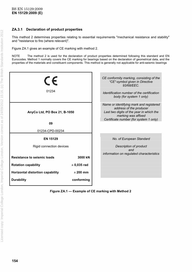
BS EN 15129:2009EN 15129:2009 (E)
154
ZA.3.1 Declaration of product properties
This method 2 determines properties relating to essential requirements "mechanical resistance and stability" and "resistance to fire (where relevant)".
Figure ZA.1 gives an example of CE marking with method 2.
NOTE The method 2 is used for the declaration of product properties determined following this standard and EN Eurocodes. Method 1 normally covers the CE marking for bearings based on the declaration of geometrical data, and the properties of the materials and constituent components. This method is generally not applicable for anti-seismic bearings
01234
CE conformity marking, consisting of the
“CE”-symbol given in Directive 93/68/EEC.
Identification number of the certification
body (for system 1 only)
AnyCo Ltd, PO Box 21, B-1050
09
01234-CPD-00234
Name or identifying mark and registered address of the producer
Last two digits of the year in which the marking was affixed
Certificate number (for system 1 only)
EN 15129
Rigid connection devices
Resistance to seismic loads 3000 kN Rotation capability ± 0,035 rad Horizontal distortion capability ± 200 mm Durability conforming
No. of European Standard
Description of product
and information on regulated characteristics
Figure ZA.1 — Example of CE marking with Method 2
Lice
nsed
cop
y: Im
peria
l Col
lege
Lon
don,
Impe
rial C
olle
ge L
ondo
n, V
ersi
on c
orre
ct a
s of
24/
09/2
012
15:1
6, (
c) T
he B
ritis
h S
tand
ards
Inst
itutio
n 20
12

BS EN 15129:2009EN 15129:2009 (E)
155
ZA.3.2 Declaration of compliance with given design specification
This method 3 determines properties relating to essential requirements "mechanical resistance and stability" and "resistance to fire (where relevant)".
The Method 3 applies in the following situations:
(a) For cases in which a structural component or kit is produced in accordance with the design details (drawings, material specifications, etc.) prepared by the designer of the works;
(b) For cases in which the producer has designed and produced a structural component or kit following the provisions of the client’s order.
Figures ZA.2a to ZA.2d and ZA.3 give, for anti-seismic bearing block, the model CE marking in the case the product is produced according to a design specification in which the properties related to mechanical resistance and stability are determined by means of design provisions applicable to the works.
Referring to the relevant Table ZA.1, the following properties shall be declared:
Load bearing capacity (compression and tension) (Axial load transmission capability);
Resistance to seismic loads/shock absorption (Survivability against repeated load cycling);
Shear modulus (Stiffness);
Rotation capability (Re-centring capability);
Friction coefficient (Energy dissipation capability);
Horizontal distortion capability (Lateral flexibility);
Durability aspects (durability against ageing, temperature, corrosion).
NOTE This method is applicable for cases not covered by Methods 1( for products off the shelf and catalogue products. This method seems not relevant for anti-seismic devices) and 2.
Lice
nsed
cop
y: Im
peria
l Col
lege
Lon
don,
Impe
rial C
olle
ge L
ondo
n, V
ersi
on c
orre
ct a
s of
24/
09/2
012
15:1
6, (
c) T
he B
ritis
h S
tand
ards
Inst
itutio
n 20
12

BS EN 15129:2009EN 15129:2009 (E)
156
01234
CE conformity marking, consisting of the
“CE”-symbol given in Directive 93/68/EEC.
Identification number of the certification body (for system 1 only)
AnyCo Ltd, PO Box 21, B-1050
09
01234-CPD-00234
Name or identifying mark and registered address of the producer
Last two digits of the year in which the marking was affixed
Certificate number (for system 1 only)
EN 15129
Rigid connection devices
Resistance to seismic loads 3000 kN Rotation capability ± 0,035 rad Horizontal distortion capability ± 200 mm Durability conforming
No. of European Standard
Description of product
and information on regulated characteristics
Figure ZA.2.a — Example of CE marking with Method 3, for system 1
01234
CE conformity marking, consisting of the
“CE”-symbol given in Directive 93/68/EEC.
Identification number of the certification body (for system 1 only)
AnyCo Ltd, PO Box 21, B-1050
09
01234-CPD-00234
Name or identifying mark and registered address of the producer
Last two digits of the year in which the marking was affixed
Certificate number (for system 1 only)
EN 15129
Fluid Viscous Damper
Load bearing capacity conformingResistance to seismic loads 1000 kN Rotation capability ± 0,035 rad Horizontal distortion capability ± 300 mm Durability conforming
No. of European Standard
Description of product
and information on regulated characteristics
Figure ZA.2.b — Example of CE marking with Method 3, for system 1 Lice
nsed
cop
y: Im
peria
l Col
lege
Lon
don,
Impe
rial C
olle
ge L
ondo
n, V
ersi
on c
orre
ct a
s of
24/
09/2
012
15:1
6, (
c) T
he B
ritis
h S
tand
ards
Inst
itutio
n 20
12

BS EN 15129:2009EN 15129:2009 (E)
157
01234
CE conformity marking, consisting of the
“CE”-symbol given in Directive 93/68/EEC.
Identification number of the certification body (for system 1 only)
AnyCo Ltd, PO Box 21, B-1050
09
01234-CPD-00234
Name or identifying mark and registered address of the producer
Last two digits of the year in which the marking was affixed
Certificate number (for system 1 only)
EN 15129
Fluid Spring Damper
Load bearing capacity conforming
Resistance to seismic loads 2000 kN
Stiffness 7000 kN/m Rotation capability ± 0,035 rad Horizontal distortion capability ± 300 mm Durability conforming
No. of European Standard
Description of product
and information on regulated characteristics
Figure ZA.2.c — Example of CE marking with Method 3, for system 1
01234
CE conformity marking, consisting of the
“CE”-symbol given in Directive 93/68/EEC.
Identification number of the certification body (for system 1 only)
AnyCo Ltd, PO Box 21, B-1050
09
01234-CPD-00234
Name or identifying mark and registered address of the producer
Last two digits of the year in which the marking was affixed
Certificate number (for system 1 only)
EN 15129
Curved Surface Slider
Load bearing capacity 5400 kN Rotation capability ± 0,01 rad Friction coefficient 0,05
Horizontal distortion capability ± 0,5 m Durability conforming
No. of European Standard
Description of product
and information on regulated characteristics
Figure ZA.2.d — Example of CE marking with Method 3, for system 1
Lice
nsed
cop
y: Im
peria
l Col
lege
Lon
don,
Impe
rial C
olle
ge L
ondo
n, V
ersi
on c
orre
ct a
s of
24/
09/2
012
15:1
6, (
c) T
he B
ritis
h S
tand
ards
Inst
itutio
n 20
12

BS EN 15129:2009EN 15129:2009 (E)
158
CE conformity marking, consisting of the
“CE”-symbol given in Directive 93/68/EEC.
AnyCo Ltd, PO Box 21, B-1050
09
Name or identifying mark and registered address of the producer
Last two digits of the year in which the marking was affixed
EN 15129
Rigid connection devices
Resistance to seismic loads 3000 kN Rotation capability ± 0,035 rad Horizontal distortion capability ± 200 mm Durability conforming
No. of European Standard
Description of product
and information on regulated characteristics
Figure ZA.3 — Example of CE marking with Method 3, for system 3
In addition to any specific information relating to dangerous substances shown above, the product should also be accompanied, when and where required and in the appropriate form, by documentation listing any other legislation on dangerous substances for which compliance is claimed, together with any information required by that legislation.
NOTE 1 European legislation without national derogations need not be mentioned.
NOTE 2 Affixing the CE marking symbol means, if a product is subject to more than one directive, that it complies with all applicable directives.
Lice
nsed
cop
y: Im
peria
l Col
lege
Lon
don,
Impe
rial C
olle
ge L
ondo
n, V
ersi
on c
orre
ct a
s of
24/
09/2
012
15:1
6, (
c) T
he B
ritis
h S
tand
ards
Inst
itutio
n 20
12

BS EN 15129:2009EN 15129:2009 (E)
159
Bibliography
[1] EN 1998-3, Eurocode 8: Design of structures for earthquake resistance – Part 3: Assessment and retrofitting of buildings
[2] EN 1998-4, Eurocode 8: Design of structures for earthquake resistance – Part 4: Silos, tanks and pipelines
[3] EN 1998-5, Eurocode 8: Design of structures for earthquake resistance – Part 5: Foundations, retaining structures and geotechnical aspects
[4] EN 1998-6, Eurocode 8: Design of structures for earthquake resistance – Part 6: Towers, masts and chimneys
[5] EN 10113-1, Hot-rolled products in weldable fine grain structural steels – Part 1: General delivery conditions
[6] EN 10137-1, Plates and wide flats made of high yield strength structural steels in the quenched and tempered or precipitation hardened conditions – Part 1: General delivery conditions
[7] EN 10137-2, Plates and wide flats made of high yield strength structural steels in the quenched and tempered or precipitation hardened conditions – Part 2: Delivery conditions for quenched for quenched and tempered steels
[8] EN 10137-3, Plates and wide flats made of high yield strength structural steels in the quenched and tempered or precipitation hardened conditions – Part 3: Delivery conditions for quenched for precipitation hardened steels
[9] EN 1337-4, Structural bearings – Part 4: Roller bearings
[10] EN 1337-5, Structural bearings – Part 5: Pot bearings
[11] EN 1337-6, Structural bearings – Part 6: Rocker bearings
[12] EN 1337-9, Structural bearings – Part 9: Protection
[13] ISO 6446, Rubber products – Bridge bearings – Specification for rubber materials
[14] James M. Kelly, Earthquake-Resistant Design with Rubber, 2nd edition, Springer-Verlag, London
[15] Gent, A.N., Lindley, P.B. (1959). The compression of bonded rubber blocks. Proc. Instn Mech. Eng, Vol. 173, No. 3, pp. 111-122
Lice
nsed
cop
y: Im
peria
l Col
lege
Lon
don,
Impe
rial C
olle
ge L
ondo
n, V
ersi
on c
orre
ct a
s of
24/
09/2
012
15:1
6, (
c) T
he B
ritis
h S
tand
ards
Inst
itutio
n 20
12

BS EN15129:2009
BSI GroupHeadquarters 389Chiswick High Road,London, W4 4AL, UKTel +44 (0)20 8996 9001Fax +44 (0)20 8996 7001www.bsigroup.com/standards
BSI - British Standards InstitutionBSI is the independent national body responsible for preparing BritishStandards. It presents the UK view on standards in Europe and at theinternational level. It is incorporated by Royal Charter.
Revisions
British Standards are updated by amendment or revision. Users of BritishStandards should make sure that they possess the latest amendments oreditions.
It is the constant aim of BSI to improve the quality of our products and services.We would be grateful if anyone finding an inaccuracy or ambiguity while usingthis British Standard would inform the Secretary of the technical committeeresponsible, the identity of which can be found on the inside front cover. Tel:+44 (0)20 8996 9000. Fax: +44 (0)20 8996 7400.
BSI offers members an individual updating service called PLUS which ensuresthat subscribers automatically receive the latest editions of standards.
Buying standards
Orders for all BSI, international and foreign standards publications should beaddressed to Customer Services. Tel: +44 (0)20 8996 9001. Fax: +44 (0)20 89967001 Email: [email protected] You may also buy directly using a debit/creditcard from the BSI Shop on the Website http://www.bsigroup.com/shop
In response to orders for international standards, it is BSI policy to supply theBSI implementation of those that have been published as British Standards,unless otherwise requested.
Information on standards
BSI provides a wide range of information on national, European andinternational standards through its Library and its Technical Help to ExportersService. Various BSI electronic information services are also available whichgive details on all its products and services. Contact Information Centre. Tel:+44 (0)20 8996 7111 Fax: +44 (0)20 8996 7048 Email: [email protected]
Subscribing members of BSI are kept up to date with standards developmentsand receive substantial discounts on the purchase price of standards. For detailsof these and other benefits contact Membership Administration. Tel: +44 (0)208996 7002 Fax: +44 (0)20 8996 7001 Email: [email protected]
Information regarding online access to British Standards via British StandardsOnline can be found at http://www.bsigroup.com/BSOL
Further information about BSI is available on the BSI website at http://www.bsigroup.com.
Copyright
Copyright subsists in all BSI publications. BSI also holds the copyright, in theUK, of the publications of the international standardization bodies. Except aspermitted under the Copyright, Designs and Patents Act 1988 no extract maybe reproduced, stored in a retrieval system or transmitted in any form or by anymeans – electronic, photocopying, recording or otherwise – without prior writtenpermission from BSI.
This does not preclude the free use, in the course of implementing the standard,of necessary details such as symbols, and size, type or grade designations. Ifthese details are to be used for any other purpose than implementation then theprior written permission of BSI must be obtained.
Details and advice can be obtained from the Copyright and Licensing Manager.Tel: +44 (0)20 8996 7070 Email: [email protected]
Lice
nsed
cop
y: Im
peria
l Col
lege
Lon
don,
Impe
rial C
olle
ge L
ondo
n, V
ersi
on c
orre
ct a
s of
24/
09/2
012
15:1
6, (
c) T
he B
ritis
h S
tand
ards
Inst
itutio
n 20
12
Related Documents