Anti-Lock Control - Traction Control COMPONENT LOCATIONS - SHEET 1 OF 2 Published : Oct 22, 2004 Item Part Number Description 1 - Hydraulic control unit with attached ABS module 2 - Stoplamp switch 3 - Right rear wheel speed sensor 4 - Left rear wheel speed sensor Page 1 of 17 Contents Page 10/21/2005 https://myvpn.dealerconnection.com/extdealerlrprod/xml/parsexml.jsp,DanaInfo=gtr.fran...

Welcome message from author
This document is posted to help you gain knowledge. Please leave a comment to let me know what you think about it! Share it to your friends and learn new things together.
Transcript
Anti-Lock Control - Traction Control
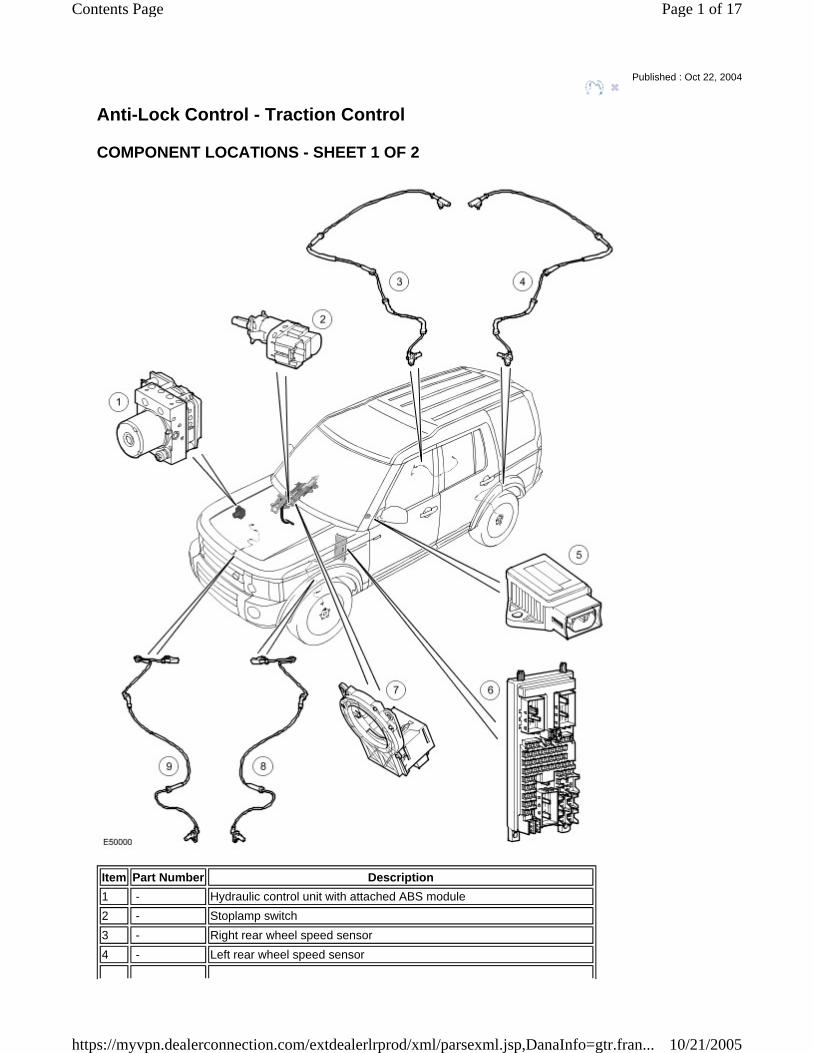
COMPONENT LOCATIONS - SHEET 1 OF 2
Published : Oct 22, 2004
Item Part Number Description 1 - Hydraulic control unit with attached ABS module 2 - Stoplamp switch3 - Right rear wheel speed sensor4 - Left rear wheel speed sensor
Page 1 of 17Contents Page
10/21/2005https://myvpn.dealerconnection.com/extdealerlrprod/xml/parsexml.jsp,DanaInfo=gtr.fran...
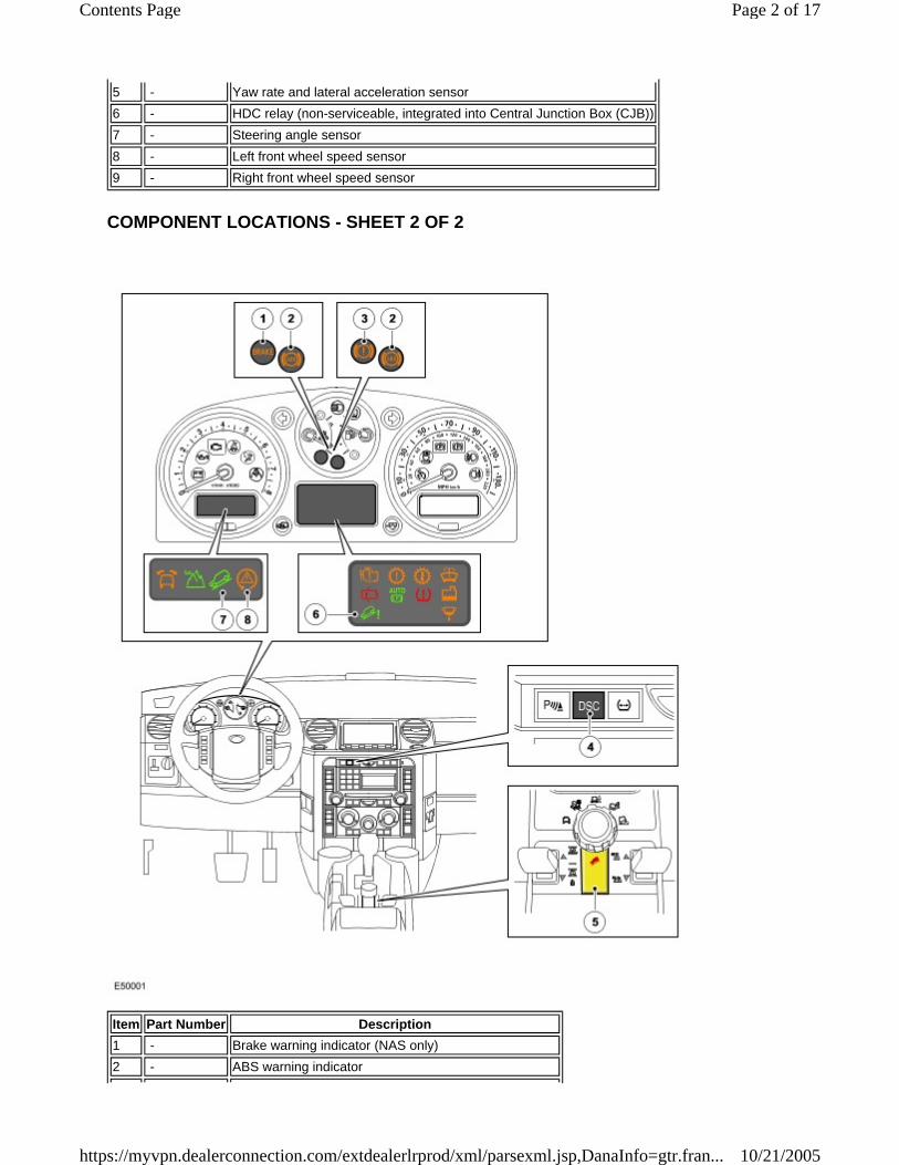
COMPONENT LOCATIONS - SHEET 2 OF 2
5 - Yaw rate and lateral acceleration sensor6 - HDC relay (non-serviceable, integrated into Central Junction Box (CJB))7 - Steering angle sensor8 - Left front wheel speed sensor9 - Right front wheel speed sensor
Item Part Number Description 1 - Brake warning indicator (NAS only)2 - ABS warning indicator
Page 2 of 17Contents Page
10/21/2005https://myvpn.dealerconnection.com/extdealerlrprod/xml/parsexml.jsp,DanaInfo=gtr.fran...
GENERAL
The anti-lock control - traction control system is based on the 4 channel Bosch 8.0 system and provides the following brake functions:
Anti-lock Braking System (ABS). Corner Brake Control (CBC). Dynamic Stability Control (DSC). Electronic Brake-force Distribution (EBD). Electronic Traction Control (ETC). Emergency Brake Assist (EBA). Engine Drag-torque Control (EDC). Hill Descent Control (HDC).
The system consists of the following components:
A DSC switch. An HDC switch. An HDC relay. A stoplamp switch. Four wheel speed sensors. A yaw rate and lateral acceleration sensor. A steering angle sensor. Warning indicators; four on vehicles with a high line instrument cluster and five on vehicles with a low line instrument cluster. A Hydraulic Control Unit (HCU) with attached ABS module.
DSC SWITCH
The DSC switch allows the DSC function to be selected off. Although Land Rover recommend that DSC is selected on for all normal driving conditions, it may be beneficial to de-select DSC, to maximize traction, under the following conditions:
If the vehicle needs to be rocked out of a hollow or a soft surface. Driving on loose surfaces or with snow chains. Driving in deep sand, snow or mud. On tracks with deep longitudinal ruts.
The DSC switch is a non-latching switch installed in the center switch pack on the instrument panel. Pressing the DSC switch connects an ignition power feed to the ABS module. With the first press of the DSC switch, the ABS module disables the DSC functions. When the DSC switch is pressed again, the ABS module re-enables the DSC functions. The DSC switch must be pressed for a minimum of 0.3 s for the ABS module to react. The DSC function is re-enabled at the beginning of each ignition cycle. The status of the DSC switch selection is shown by the DSC warning indicator. The DSC warning indicator is off while DSC is selected on, and continuously illuminated while DSC is selected off. A DSC switch request to disable DSC is ignored if the air suspension system has failed, or is in off-road height at speeds above 60 km/h (37.5 mph). To guard against incorrect operation or a broken switch, if the input from the DSC switch is held high for more than one minute, a failure is stored in the ABS module. Even if DSC is deselected, driving manoeuvres with extreme yaw or lateral acceleration may trigger DSC activity to assist
3 - Brake warning indicator (all except NAS)4 - DSC switch5 - HDC switch6 - HDC warning indicator (low line instrument cluster only)7 - HDC information indicator8 - DSC warning indicator
Page 3 of 17Contents Page
10/21/2005https://myvpn.dealerconnection.com/extdealerlrprod/xml/parsexml.jsp,DanaInfo=gtr.fran...

vehicle stability.
HDC SWITCH
The HDC switch controls the selection of the HDC function. The HDC switch is a non-latching switch installed on the center console, to the rear of the gear shift lever. Pressing and releasing the HDC switch momentarily connects an ignition power feed to the ABS module. With the first press and release of the HDC switch, the ABS module enables operation of the HDC function. When the HDC switch is pressed and released again, the ABS module disables operation of the HDC function. To guard against incorrect operation or a broken switch, if the switch is pressed for more than 10 seconds no change of state occurs. If the input from the HDC switch is held high for more than one minute, a failure is stored in the ABS module.
HDC RELAY
The HDC relay is used to illuminate the stoplamps when the brakes are activated during HDC operation and during dynamic application of the parking brake. The HDC relay is a non-serviceable, solid state relay on the circuit board of the Central Junction Box (CJB). Operation of the HDC relay is controlled by the ABS module switching the coil to ground. The ABS module monitors brake system hydraulic pressure and energizes the HDC relay during active braking. A pressure threshold and time filter prevent the stoplamps from flickering when HDC is braking.
STOPLAMP SWITCH
The stoplamp switch is mounted in the brake pedal bracket and operated by the brake pedal. The stoplamp switch is a two pole switch: The Brake Switch (BS) pole supplies a brake pedal status signal to the ABS module; the Brake Lamp Switch (BLS) pole operates the stoplamps and also supplies a brake pedal status signal to the ABS module and to the Engine Control Module (ECM). While the brake pedal is released:
The BS contacts are closed, and connect an ignition power feed from the Central Junction Box (CJB) to the ABS module. The BLS contacts are open.
When the brake pedal is pressed:
The BS contacts open. The BLS contacts close, and connect an ignition power feed from the CJB to the three stoplamps, the ABS module and the ECM.
The ABS module monitors the status inputs from the stoplamp switch and broadcasts the brake pedal status and an associated quality factor on the high speed Controller Area Network (CAN) bus.
WHEEL SPEED SENSORS
Page 4 of 17Contents Page
10/21/2005https://myvpn.dealerconnection.com/extdealerlrprod/xml/parsexml.jsp,DanaInfo=gtr.fran...
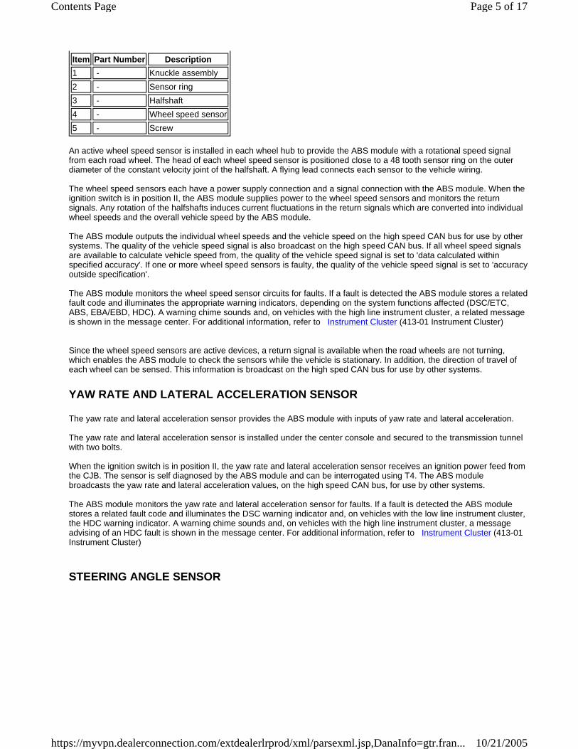
An active wheel speed sensor is installed in each wheel hub to provide the ABS module with a rotational speed signal from each road wheel. The head of each wheel speed sensor is positioned close to a 48 tooth sensor ring on the outer diameter of the constant velocity joint of the halfshaft. A flying lead connects each sensor to the vehicle wiring. The wheel speed sensors each have a power supply connection and a signal connection with the ABS module. When the ignition switch is in position II, the ABS module supplies power to the wheel speed sensors and monitors the return signals. Any rotation of the halfshafts induces current fluctuations in the return signals which are converted into individual wheel speeds and the overall vehicle speed by the ABS module. The ABS module outputs the individual wheel speeds and the vehicle speed on the high speed CAN bus for use by other systems. The quality of the vehicle speed signal is also broadcast on the high speed CAN bus. If all wheel speed signals are available to calculate vehicle speed from, the quality of the vehicle speed signal is set to 'data calculated within specified accuracy'. If one or more wheel speed sensors is faulty, the quality of the vehicle speed signal is set to 'accuracy outside specification'. The ABS module monitors the wheel speed sensor circuits for faults. If a fault is detected the ABS module stores a relatedfault code and illuminates the appropriate warning indicators, depending on the system functions affected (DSC/ETC, ABS, EBA/EBD, HDC). A warning chime sounds and, on vehicles with the high line instrument cluster, a related message is shown in the message center. For additional information, refer to Instrument Cluster (413-01 Instrument Cluster) Since the wheel speed sensors are active devices, a return signal is available when the road wheels are not turning, which enables the ABS module to check the sensors while the vehicle is stationary. In addition, the direction of travel of each wheel can be sensed. This information is broadcast on the high sped CAN bus for use by other systems.
YAW RATE AND LATERAL ACCELERATION SENSOR
The yaw rate and lateral acceleration sensor provides the ABS module with inputs of yaw rate and lateral acceleration. The yaw rate and lateral acceleration sensor is installed under the center console and secured to the transmission tunnel with two bolts. When the ignition switch is in position II, the yaw rate and lateral acceleration sensor receives an ignition power feed from the CJB. The sensor is self diagnosed by the ABS module and can be interrogated using T4. The ABS module broadcasts the yaw rate and lateral acceleration values, on the high speed CAN bus, for use by other systems. The ABS module monitors the yaw rate and lateral acceleration sensor for faults. If a fault is detected the ABS module stores a related fault code and illuminates the DSC warning indicator and, on vehicles with the low line instrument cluster, the HDC warning indicator. A warning chime sounds and, on vehicles with the high line instrument cluster, a message advising of an HDC fault is shown in the message center. For additional information, refer to Instrument Cluster (413-01 Instrument Cluster)
STEERING ANGLE SENSOR
Item Part Number Description 1 - Knuckle assembly2 - Sensor ring3 - Halfshaft4 - Wheel speed sensor5 - Screw
Page 5 of 17Contents Page
10/21/2005https://myvpn.dealerconnection.com/extdealerlrprod/xml/parsexml.jsp,DanaInfo=gtr.fran...
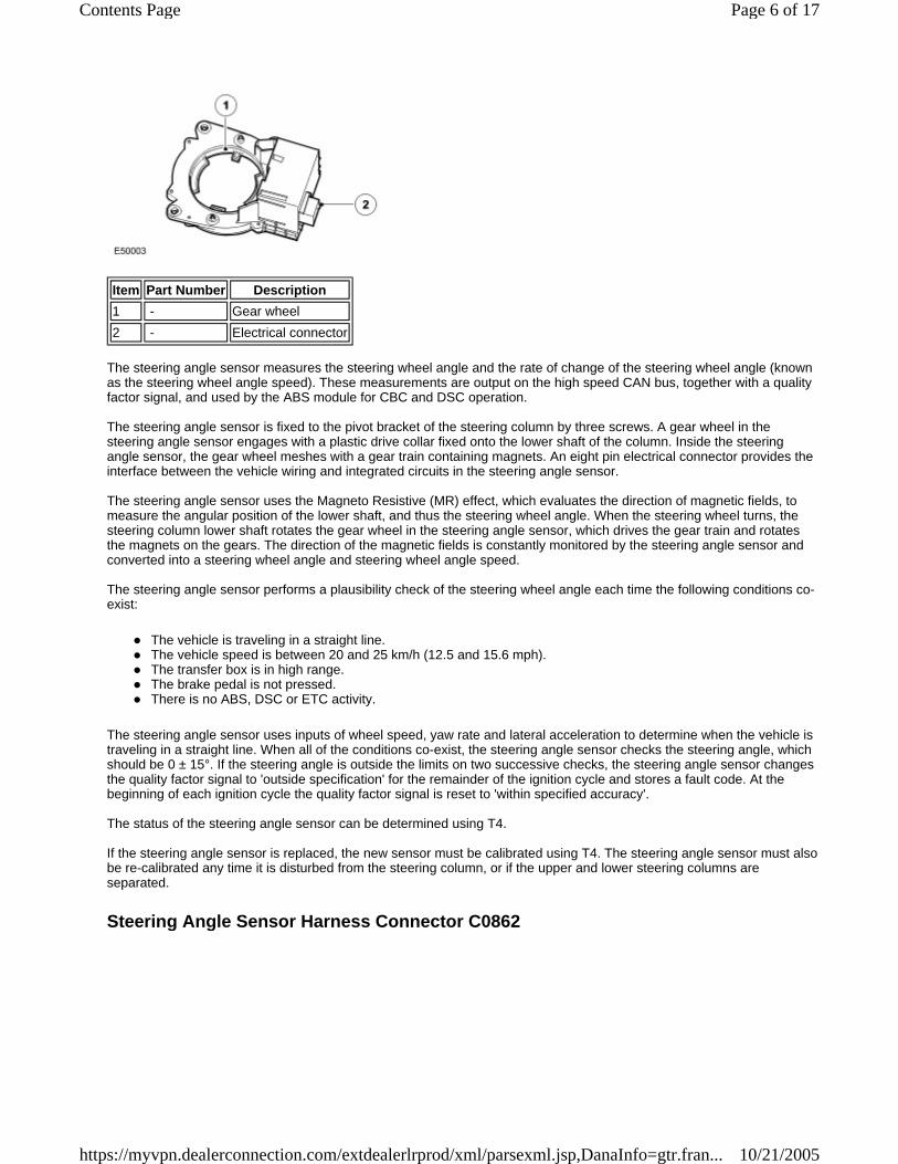
The steering angle sensor measures the steering wheel angle and the rate of change of the steering wheel angle (known as the steering wheel angle speed). These measurements are output on the high speed CAN bus, together with a quality factor signal, and used by the ABS module for CBC and DSC operation. The steering angle sensor is fixed to the pivot bracket of the steering column by three screws. A gear wheel in the steering angle sensor engages with a plastic drive collar fixed onto the lower shaft of the column. Inside the steering angle sensor, the gear wheel meshes with a gear train containing magnets. An eight pin electrical connector provides the interface between the vehicle wiring and integrated circuits in the steering angle sensor. The steering angle sensor uses the Magneto Resistive (MR) effect, which evaluates the direction of magnetic fields, to measure the angular position of the lower shaft, and thus the steering wheel angle. When the steering wheel turns, the steering column lower shaft rotates the gear wheel in the steering angle sensor, which drives the gear train and rotates the magnets on the gears. The direction of the magnetic fields is constantly monitored by the steering angle sensor and converted into a steering wheel angle and steering wheel angle speed. The steering angle sensor performs a plausibility check of the steering wheel angle each time the following conditions co-exist:
The vehicle is traveling in a straight line. The vehicle speed is between 20 and 25 km/h (12.5 and 15.6 mph). The transfer box is in high range. The brake pedal is not pressed. There is no ABS, DSC or ETC activity.
The steering angle sensor uses inputs of wheel speed, yaw rate and lateral acceleration to determine when the vehicle is traveling in a straight line. When all of the conditions co-exist, the steering angle sensor checks the steering angle, which should be 0 ± 15°. If the steering angle is outside the limits on two successive checks, the steering angle sensor changes the quality factor signal to 'outside specification' for the remainder of the ignition cycle and stores a fault code. At the beginning of each ignition cycle the quality factor signal is reset to 'within specified accuracy'. The status of the steering angle sensor can be determined using T4. If the steering angle sensor is replaced, the new sensor must be calibrated using T4. The steering angle sensor must also be re-calibrated any time it is disturbed from the steering column, or if the upper and lower steering columns are separated.
Steering Angle Sensor Harness Connector C0862
Item Part Number Description 1 - Gear wheel2 - Electrical connector
Page 6 of 17Contents Page
10/21/2005https://myvpn.dealerconnection.com/extdealerlrprod/xml/parsexml.jsp,DanaInfo=gtr.fran...
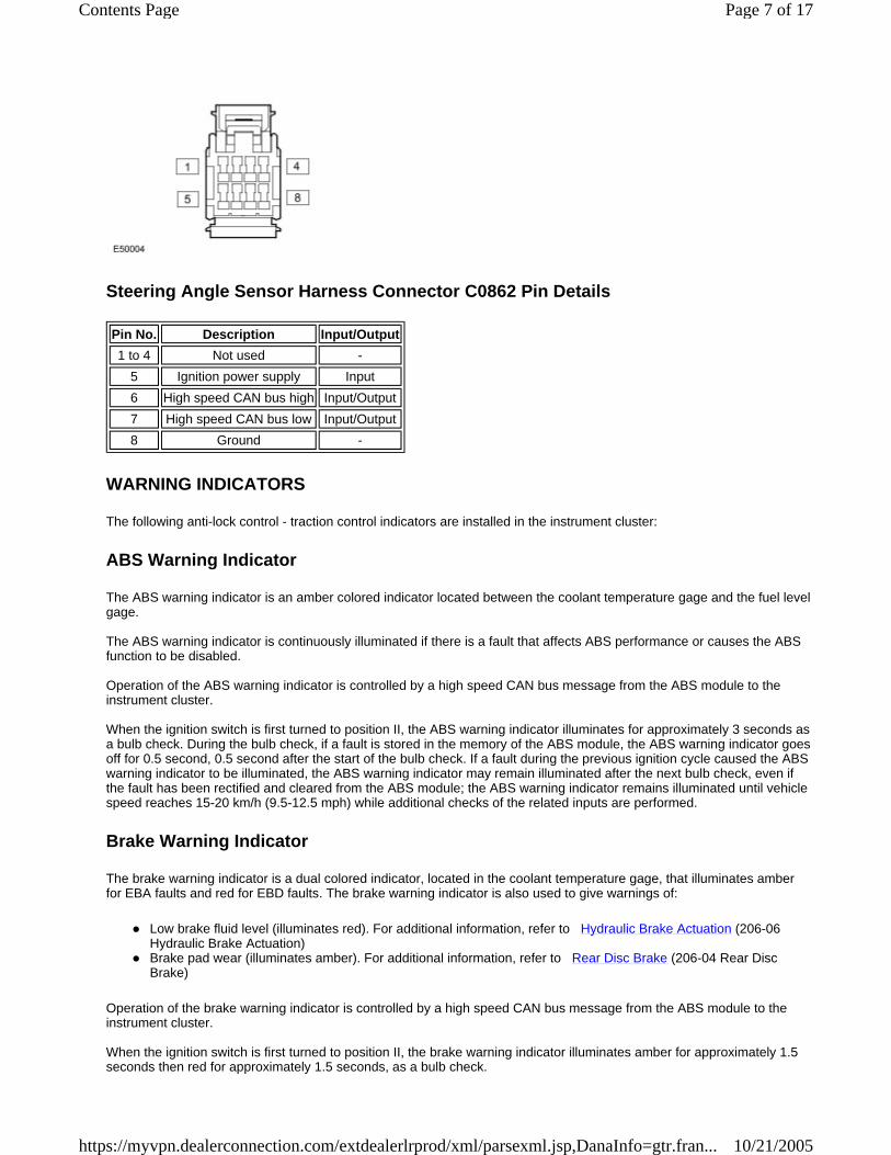
Steering Angle Sensor Harness Connector C0862 Pin Details
WARNING INDICATORS
The following anti-lock control - traction control indicators are installed in the instrument cluster:
ABS Warning Indicator
The ABS warning indicator is an amber colored indicator located between the coolant temperature gage and the fuel level gage. The ABS warning indicator is continuously illuminated if there is a fault that affects ABS performance or causes the ABS function to be disabled. Operation of the ABS warning indicator is controlled by a high speed CAN bus message from the ABS module to the instrument cluster. When the ignition switch is first turned to position II, the ABS warning indicator illuminates for approximately 3 seconds as a bulb check. During the bulb check, if a fault is stored in the memory of the ABS module, the ABS warning indicator goes off for 0.5 second, 0.5 second after the start of the bulb check. If a fault during the previous ignition cycle caused the ABS warning indicator to be illuminated, the ABS warning indicator may remain illuminated after the next bulb check, even if the fault has been rectified and cleared from the ABS module; the ABS warning indicator remains illuminated until vehicle speed reaches 15-20 km/h (9.5-12.5 mph) while additional checks of the related inputs are performed.
Brake Warning Indicator
The brake warning indicator is a dual colored indicator, located in the coolant temperature gage, that illuminates amber for EBA faults and red for EBD faults. The brake warning indicator is also used to give warnings of:
Low brake fluid level (illuminates red). For additional information, refer to Hydraulic Brake Actuation (206-06 Hydraulic Brake Actuation) Brake pad wear (illuminates amber). For additional information, refer to Rear Disc Brake (206-04 Rear Disc Brake)
Operation of the brake warning indicator is controlled by a high speed CAN bus message from the ABS module to the instrument cluster. When the ignition switch is first turned to position II, the brake warning indicator illuminates amber for approximately 1.5 seconds then red for approximately 1.5 seconds, as a bulb check.
Pin No. Description Input/Output 1 to 4 Not used -
5 Ignition power supply Input 6 High speed CAN bus high Input/Output 7 High speed CAN bus low Input/Output 8 Ground -
Page 7 of 17Contents Page
10/21/2005https://myvpn.dealerconnection.com/extdealerlrprod/xml/parsexml.jsp,DanaInfo=gtr.fran...
DSC Warning Indicator
The DSC warning indicator is an amber colored warning indicator located in the tachometer. Each time the DSC or the ETC function is active, the DSC warning indicator flashes at 2 Hz. If DSC has been selected off,or there is a fault that disables the DSC or the ETC function, the DSC warning indicator is continuously illuminated. If DSC has been selected off, vehicles with the high line instrument cluster also display a message, advising that DSC is switched off. For additional information, refer to Instrument Cluster (413-01 Instrument Cluster) Operation of the DSC warning indicator is controlled by a high speed CAN bus message from the ABS module to the instrument cluster. When the ignition switch is first turned to position II, the DSC warning indicator illuminates for approximately 3 seconds as a bulb check. If a fault during the previous ignition cycle caused the DSC warning indicator to be illuminated, the DSC warning indicator may remain illuminated after the next bulb check, even if the fault has been rectified and cleared from the ABS module; the DSC warning indicator may remain illuminated during vehicle operation while additional checks of the related inputs are performed.
HDC Information Indicator
The HDC information indicator is a green colored indicator located in the tachometer. The HDC information indicator is continuously illuminated while the HDC function is selected on and the vehicle is within the parameters for HDC operation; when the vehicle is outside the parameters for HDC operation, the HDC information indicator is flashed at 2 Hz. Operation of the HDC information indicator is controlled by a high speed CAN bus message from the ABS module to the instrument cluster.
HDC Warning Indicator
On the low line instrument cluster, the HDC warning indicator is an amber colored indicator located between the tachometer and the speedometer. On vehicles with the high line instrument cluster, the HDC warning indicator consists of a message in the message center. On the low line instrument cluster the HDC warning indicator is continuously illuminated if there is a fault that affects the HDC function, and flashed at 2 Hz if the HDC function is temporarily unavailable because of brake overheat. On the high line instrument cluster, appropriate messages are displayed in the message center if there is a fault that affects the HDC function, or if the HDC function is temporarily unavailable because of brake overheat. For additional information, refer to Instrument Cluster (413-01 Instrument Cluster) Operation of the HDC warning indicator is controlled by a high speed CAN bus message from the ABS module to the instrument cluster. On the low line instrument cluster, when the ignition switch is first turned to position II, the HDC warning indicator illuminates for approximately 3 seconds as a bulb check.
HCU
The HCU is a 4 channel unit that modulates the supply of hydraulic pressure to the brakes under the control of the ABS module. The HCU is attached by three mounting bushes to a bracket in the plenum box on the driver side of the engine compartment. Hydraulic pipes connect the HCU to the master cylinder and the brakes. For additional information, refer to Hydraulic Brake Actuation (206-06 Hydraulic Brake Actuation) The primary and secondary outlets of the master cylinder are connected to primary and secondary circuits within the HCU. The primary circuit in the HCU has separate outlet ports to the front brakes. The secondary circuit in the HCU has
Page 8 of 17Contents Page
10/21/2005https://myvpn.dealerconnection.com/extdealerlrprod/xml/parsexml.jsp,DanaInfo=gtr.fran...

separate outlet ports to the rear brakes. Each of the circuits in the HCU contain the following components to control the supply of hydraulic pressure to the brakes:
A normally open, solenoid operated, pilot valve, to enable active braking. A normally closed, solenoid operated, priming valve, to connect the brake fluid reservoir to the return pump during active braking. A return pump, to generate hydraulic pressure for active braking and return brake fluid to the reservoir. Normally open, solenoid operated, inlet valves and normally closed, solenoid operated, outlet valves, to modulate the hydraulic pressure in the individual brakes. An accumulator and a relief valve, to allow the fast release of pressure from the brakes. Filters, to protect the components from contamination.
The primary circuit also incorporates a pressure sensor to provide the ABS module with a hydraulic pressure signal. Contact pins on the HCU mate with contacts on the ABS module to provide the electrical connections from the ABS module to the return pump motor and the pressure sensor. The solenoids that operate the valves are installed in the ABS module. Replacement HCU are supplied pre-filled. After installation on the vehicle, T4 must be used to operate the solenoid valves and the return pump to ensure correct bleeding of the HCU and brake circuits.
Schematic of HCU
Item Part Number Description
Page 9 of 17Contents Page
10/21/2005https://myvpn.dealerconnection.com/extdealerlrprod/xml/parsexml.jsp,DanaInfo=gtr.fran...
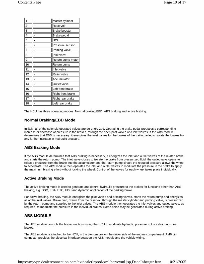
The HCU has three operating modes: Normal braking/EBD, ABS braking and active braking.
Normal Braking/EBD Mode
Initially, all of the solenoid operated valves are de-energized. Operating the brake pedal produces a corresponding increase or decrease of pressure in the brakes, through the open pilot valves and inlet valves. If the ABS module determines that EBD is necessary, it energizes the inlet valves for the brakes of the trailing axle, to isolate the brakes fromany further increase in hydraulic pressure.
ABS Braking Mode
If the ABS module determines that ABS braking is necessary, it energizes the inlet and outlet valves of the related brake and starts the return pump. The inlet valve closes to isolate the brake from pressurized fluid; the outlet valve opens to release pressure from the brake into the accumulator and the return pump circuit; the reduced pressure allows the wheel to accelerate. The ABS module then operates the inlet and outlet valves to modulate the pressure in the brake to apply the maximum braking effort without locking the wheel. Control of the valves for each wheel takes place individually.
Active Braking Mode
The active braking mode is used to generate and control hydraulic pressure to the brakes for functions other than ABS braking, e.g. DSC, EBA, ETC, HDC and dynamic application of the parking brake. For active braking, the ABS module energizes the pilot valves and priming valves, starts the return pump and energizes all of the inlet valves. Brake fluid, drawn from the reservoir through the master cylinder and priming valve, is pressurized by the return pump and supplied to the inlet valves. The ABS module then operates the inlet valves and outlet valves, as required, to modulate the pressure in the individual brakes. Some noise may be generated during active braking.
ABS MODULE
The ABS module controls the brake functions using the HCU to modulate hydraulic pressure to the individual wheel brakes. The ABS module is attached to the HCU, in the plenum box on the driver side of the engine compartment. A 46 pin connector provides the electrical interface between the ABS module and the vehicle wiring.
1 - Master cylinder2 - Reservoir3 - Brake booster4 - Brake pedal5 - HCU6 - Pressure sensor7 - Priming valve8 - Pilot valve9 - Return pump motor10 - Return pump11 - Inlet valve12 - Relief valve13 - Accumulator14 - Outlet valve15 - Left front brake16 - Right front brake17 - Right rear brake18 - Left rear brake
Page 10 of 17Contents Page
10/21/2005https://myvpn.dealerconnection.com/extdealerlrprod/xml/parsexml.jsp,DanaInfo=gtr.fran...
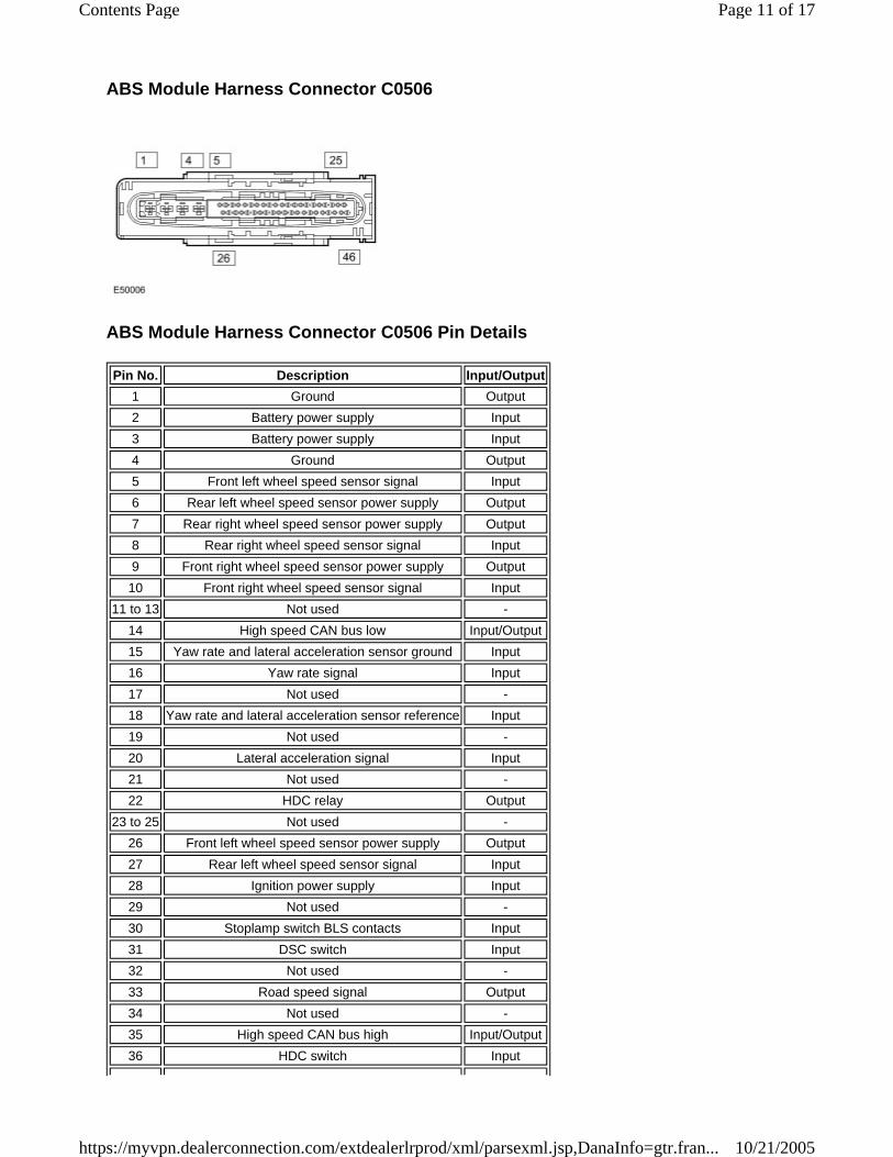
ABS Module Harness Connector C0506
ABS Module Harness Connector C0506 Pin Details
Pin No. Description Input/Output1 Ground Output 2 Battery power supply Input 3 Battery power supply Input 4 Ground Output 5 Front left wheel speed sensor signal Input 6 Rear left wheel speed sensor power supply Output 7 Rear right wheel speed sensor power supply Output 8 Rear right wheel speed sensor signal Input 9 Front right wheel speed sensor power supply Output 10 Front right wheel speed sensor signal Input
11 to 13 Not used - 14 High speed CAN bus low Input/Output 15 Yaw rate and lateral acceleration sensor ground Input 16 Yaw rate signal Input 17 Not used - 18 Yaw rate and lateral acceleration sensor reference Input 19 Not used - 20 Lateral acceleration signal Input 21 Not used - 22 HDC relay Output
23 to 25 Not used - 26 Front left wheel speed sensor power supply Output 27 Rear left wheel speed sensor signal Input 28 Ignition power supply Input 29 Not used - 30 Stoplamp switch BLS contacts Input 31 DSC switch Input 32 Not used - 33 Road speed signal Output 34 Not used - 35 High speed CAN bus high Input/Output 36 HDC switch Input
Page 11 of 17Contents Page
10/21/2005https://myvpn.dealerconnection.com/extdealerlrprod/xml/parsexml.jsp,DanaInfo=gtr.fran...

SYSTEM OPERATION
ABS
ABS controls the speed of all road wheels to ensure optimum wheel slip when braking at the adhesion limit. This prevents the wheels from locking, which helps to retain effective steering control of the vehicle. On the front axle, the brake pressure is modulated separately for each wheel. On the rear axle, brake pressure is modulated by select low. Select low applies the same pressure to both rear brakes, with the pressure level being determined by the wheel on the lower friction surface. This maintains rear stability on split friction surfaces.
CBC
CBC influences the brake pressures, below the DSC and ABS thresholds, to counteract the yawing moment produced when braking in a corner. CBC produces a correction torque by limiting the brake pressure on one side of the vehicle.
DSC
DSC uses the brakes and powertrain torque control to help maintain the lateral stability of the vehicle. While the ignition is on the DSC function is permanently enabled unless selected off by the DSC switch. Even if DSC is deselected, driving manoeuvres with extreme yaw or lateral acceleration may trigger DSC activity to assist vehicle stability. DSC enhances driving safety in abrupt manoeuvres and in understeer or oversteer situations which may occur in a bend. The ABS module monitors the yaw rate and lateral acceleration of the vehicle, and the steering input, then selectively applies individual brakes and signals for powertrain torque adjustments to reduce understeer or oversteer. In general: in an understeering situation, the inner wheels are braked to counteract the yaw movement towards the outer edge of the bend; in an oversteering situation, the outer wheels are braked to prevent the rear end of the vehicle from pushing towards the outer edge of the bend. The ABS module monitors the tracking stability of the vehicle using inputs from the wheel speed sensors, the steering angle sensor and the yaw rate and lateral acceleration sensor. The tracking stability is compared with stored target data and, whenever the tracking stability deviates from the target data, the ABS module intervenes by applying the appropriate brakes. On vehicles with an automatic transmission, when the DSC function is active, the ABS module also signals the Transmission Control Module (TCM) to prevent gear shifts. If necessary, the ABS module also signals:
The ECM, to reduce engine torque. The transfer box control module, to adjust the locking torque of the center differential. The rear differential control module, to adjust the locking torque of the rear differential.
The DSC function overrides the differential locking torque requests from the terrain response system.
EBD
EBD limits the brake pressure applied to the rear wheels. When the brakes are applied, the weight of the vehicle transfers forwards, which reduces the ability of the rear wheels to transfer braking effort to the road surface. This can cause the rear wheels to slip and make the vehicle unstable. EBD uses the anti-lock braking hardware to automatically optimize the pressure of the rear brakes, below the point where anti-lock braking would be invoked. Only the rear axle is under EBD control.
ETC
37 Yaw rate and lateral acceleration sensor test Output 38 to 40 Not used -
41 Stoplamp switch BS contacts Input 42 to 46 Not used -
Page 12 of 17Contents Page
10/21/2005https://myvpn.dealerconnection.com/extdealerlrprod/xml/parsexml.jsp,DanaInfo=gtr.fran...

ETC attempts to optimize forward traction by reducing engine torque or braking a spinning wheel until it regains grip. ETC is activated if an individual wheel speed is above that of the vehicle reference speed (positive slip) and the brake pedal is not pressed. The spinning wheel is braked, allowing the excess torque to be transmitted to the non spinning wheels through the drive line. If necessary, the ABS module also sends a high speed CAN bus message to the ECM to request a reduction in engine torque. Torque reduction requests are for either a slow or fast response: a slow response requests a reduction of throttle angle (4.0L and 4.4L only); a fast response requests an ignition cut-off (4.0L and 4.4L) or a fuel cut-off (2.7L Diesel). When the DSC function is selected off with the DSC switch, the engine torque reduction feature is disabled. On vehicles with an automatic transmission, when the ETC function is active the ABS module also signals the TCM to prevent gear shifts.
EBA
EBA assists the driver, in emergency braking situations, by automatically maximizing the braking effort. There are two situations when the ABS module will invoke EBA: when the brake pedal is pressed very suddenly and when the brake pedal is pressed hard enough to bring the front brakes into ABS operation. When the brake pedal is pressed very suddenly, the ABS module increases the hydraulic pressure to all of the brakes until they reach the threshold for ABS operation, thus applying the maximum braking effort for the available traction. The ABS module monitors for the sudden application of the brakes using the inputs from the stoplamp switch and from the pressure sensor in the HCU. With the brake pedal pressed, if the rate of increase of hydraulic pressure exceeds the predetermined limit, the ABS module invokes emergency braking. When the brake pedal is pressed hard enough to bring the front brakes into ABS operation, the ABS module increases the hydraulic pressure to the rear brakes up to the ABS threshold. EBA operation continues until the driver releases the brake pedal enough for the hydraulic pressure in the HCU to drop below a threshold value stored in the ABS module.
EDC
EDC prevents wheel slip caused by any of the following:
A sudden decrease in engine torque when the accelerator is suddenly released. The sudden engagement of the clutch after a downshift on manual transmission vehicles. A downshift using the CommandShift™ on automatic transmission vehicles.
When the ABS module detects the onset of wheel slip without the brakes being applied it signals the ECM, on the high speed CAN bus, to request a momentary increase in engine torque.
HDC
HDC uses brake intervention to control vehicle speed and acceleration during low speed descents in off-road and low grip on-road conditions. Generally, equal pressure is applied to all four brakes, but pressure to individual brakes can be modified by the ABS and DSC functions to retain stability. Selection of the HDC function is controlled by the HDC switch on the center console. HDC operates in both high and low ranges, at vehicle speeds up to 50 km/h (31.3 mph). On manual transmission vehicles, HDC may be used in first and reverse gears in high range and all gears in low range. Once the vehicle is moving, the clutch pedal should be fully released. The vehicle should not be driven with HDC active and the transmission in neutral. On automatic transmission vehicles, HDC may be used in D, R and CommandShift 1 in high range, and in D, R and all CommandShift gears in low range. When in D, the transmission control module will automatically select the most appropriate gear. The vehicle should not be driven with HDC active and the transmission in N. HDC can be selected at speeds up to 80 km/h (50 mph), but will only be enabled at speeds below 50 km/h (31.3 mph). When HDC is selected:
At speeds up to 50 km/h (31.3 mph), the HDC information indicator is permanently illuminated if a valid gear is selected and, on manual transmission vehicles, the clutch pedal is not depressed.
Page 13 of 17Contents Page
10/21/2005https://myvpn.dealerconnection.com/extdealerlrprod/xml/parsexml.jsp,DanaInfo=gtr.fran...

At speeds from >50 to 80 km/h (>31.3 to 50 mph) the HDC information indicator flashes and, on vehicles with the high line instrument cluster, a message advising that the speed is too high is displayed in the message center. For additional information, refer to Instrument Cluster (413-01 Instrument Cluster) If the HDC switch is pressed while vehicle speed is more than 80 km/h (50 mph), the HDC information indicator will not illuminate and HDC will not be selected. If the speed reaches 80 km/h (50 mph) or more, a warning chime sounds, the HDC function is switched off, the information indicator goes off and, on vehicles with the high line instrument cluster, a message advising that HDC has been switched off is displayed in the message center.
When HDC is enabled, the ABS module calculates a target speed and compares this with the actual vehicle speed. The ABS module then operates the HCU, in the active braking mode, as required to achieve and maintain the target speed. During active braking for HDC, the ABS module also energizes the HDC relay to operate the stop lamps. Applying the footbrakes during active braking may result in a pulse through the brake pedal, which is normal. The target speed varies, between minimum and maximum values for each gear and transmission range, depending on driver inputs through the foot pedals. If the foot pedals are not operated, the ABS module adopts a default target speed.
Low Range Target Speeds
High Range Target Speeds
The target speed is varied between the minimum and maximum values using the accelerator pedal. The target speed can also be varied by pressing the speed control '+' and '-' buttons (where fitted). For additional information, refer to Speed Control (310-03A Speed Control) For additional information, refer to Speed Control (310-03B Speed Control - 2.7L Diesel) During changes of target speed, the ABS module limits deceleration and acceleration to -0.5 m/s2 (-1.65 ft/s2) and +0.5 m/s2 (+1.65 ft/s2) respectively. On manual transmission models target speed changes are suspended during gear changes, to prevent unwanted braking when the accelerator pedal is released to change gear. The ABS module determines a gear change is occurring from:
Gear position information on the high speed CAN bus. The rate of release of the accelerator pedal. The status of the clutch pedal.
To provide a safe transition from active braking to brakes off, the ABS module invokes a fade out strategy, which gradually discontinues the braking effort, if it detects any of the following during active braking:
Limit Speed, km/h (mph) Gear
Automatic Transmission Manual Transmission 1, R D, 2 to 6 1, R 2 to 6
Default 3.5 (2.19) 6 (3.75) 3.5 (2.19) 6 (3.75) Minimum 3.5 (2.19) 3.5 (2.19) 3.5 (2.19) 3.5 (2.19) Maximum 20 (12.5) 20 (12.5) 20 (12.5) 20 (12.5)
Limit Speed, km/h (mph) Gear
Automatic Transmission Manual Transmission 1, R D 1, R
Default 6 (3.75) 10 (6.25) 6 (3.75) Minimum 6 (3.75) 6 (3.75) 6 (3.75) Maximum 20 (12.5) 20 (12.5) 20 (12.5)
Page 14 of 17Contents Page
10/21/2005https://myvpn.dealerconnection.com/extdealerlrprod/xml/parsexml.jsp,DanaInfo=gtr.fran...

HDC selected off with the HDC switch. Failure of a component used by HDC, but not critical to fade out function. Accelerator pedal pressed when transmission is in neutral. Brake overheat.
If fade out is invoked because of deselection or component failure, the HDC function is cancelled by the ABS module. If fade out is invoked because the accelerator pedal is pressed with the transmission in neutral, or because of brake overheat, the HDC function remains in standby and resumes operation when the accelerator pedal is released or the brakes have cooled. The fade out strategy increases the target speed, at a constant acceleration rate of 0.5 m/s2 (1.65 ft/s2), until the maximum target speed is reached or until no active braking is required for 0.5 s. If the accelerator pedal is positioned within the range that influences target speed, the acceleration rate is increased to 1.0 m/s2 (3.3 ft/s2). When fade out is invoked because of component failure, a warning chime sounds and the HDC information indicator is extinguished. The HDC warning indicator is illuminated (low line instrument cluster) or a message advising there is a fault is displayed in the message center (high line instrument cluster). When fade out is invoked because of brake overheat on vehicles with the high line instrument cluster, a message advising that HDC is temporarily unavailable is displayed. On vehicles with the low line instrument cluster, the HDC warning indicator flashes. At the end of fade out, the HDC information indicator flashes. The flashing indicators and/or message continue while HDC remains selected until the brakes have cooled. To monitor for brake overheat, the ABS module monitors the amount of braking activity and, from this, estimates the temperature of each brake. If the estimated temperature of any brake exceeds a preset limit, the ABS module invokes the fade out strategy. After the fade out cycle, the HDC function is re-enabled when the ABS module estimates that all of the brake temperatures are at less than 64% of the temperature limit.
ANTI-LOCK CONTROL DIAGRAM
NOTE :
A = Hardwired connections; D = High speed CAN bus
Page 15 of 17Contents Page
10/21/2005https://myvpn.dealerconnection.com/extdealerlrprod/xml/parsexml.jsp,DanaInfo=gtr.fran...
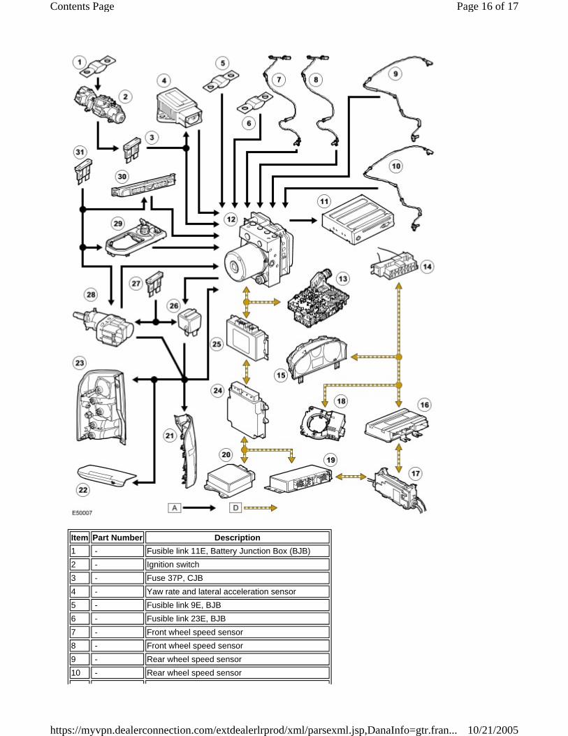
Item Part Number Description 1 - Fusible link 11E, Battery Junction Box (BJB)2 - Ignition switch3 - Fuse 37P, CJB4 - Yaw rate and lateral acceleration sensor5 - Fusible link 9E, BJB6 - Fusible link 23E, BJB7 - Front wheel speed sensor8 - Front wheel speed sensor9 - Rear wheel speed sensor10 - Rear wheel speed sensor
Page 16 of 17Contents Page
10/21/2005https://myvpn.dealerconnection.com/extdealerlrprod/xml/parsexml.jsp,DanaInfo=gtr.fran...
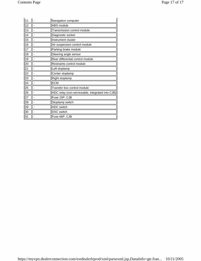
11 - Navigation computer12 - ABS module13 - Transmission control module14 - Diagnostic socket15 - Instrument cluster16 - Air suspension control module17 - Parking brake module18 - Steering angle sensor19 - Rear differential control module20 - Restraints control module21 - Left stoplamp22 - Center stoplamp23 - Right stoplamp24 - ECM25 - Transfer box control module26 - HDC relay (non-serviceable, integrated into CJB)27 - Fuse 15P, CJB28 - Stoplamp switch29 - HDC switch30 - DSC switch31 - Fuse 66P, CJB
Page 17 of 17Contents Page
10/21/2005https://myvpn.dealerconnection.com/extdealerlrprod/xml/parsexml.jsp,DanaInfo=gtr.fran...
Related Documents