ANTHONY International Installation Manual Models : 401B·1KDB COOLRITE·FREEZERITE Part No. 99-16379-S001

Welcome message from author
This document is posted to help you gain knowledge. Please leave a comment to let me know what you think about it! Share it to your friends and learn new things together.
Transcript

ANTHONY International Installation Manual Models:
401B·1KDB
COOLRITE·FREEZERITE Part No. 99-16379-S001

ANTHONY International TABLE OF CONTENTS
NOVEMBER 2006 i
I. FRAME INSTALLATION 1
SHIMMING 1 TO INSTALL THE FRAME 1 FRAME ELECTRICAL WIRING CONNECTIONS 2
II. DOOR INSTALLATION 3
TO INSTALL THE 401B/1KDB DOOR ASSEMBLY 3 TO REMOVE THE DOOR ASSEMBLY 3 TO REVERSE THE DOOR SWING (MODEL 1KDB ONLY) 4 TORQUEMASTER AND SAG ADJUSTMENT (MODEL 401B AND 1KDB) 4 TO INSTALL THE COOLRITE/FREEZERITE DOOR ASSEMBLY 5 TO REMOVE THE DOOR ASSEMBLY 6 TORQUE RITE ADJUSTMENT 6

ANTHONY International FRAME INSTALLATION
NOVEMBER 2006 1
I. FRAME INSTALLATION Read instructions completely before installing frame.
● Clearance between the frame sill and the case bottom or floor is mandated by local building codes. ● Sill net opening must be at minimum of two inches in height. ● Sill must be completely level.
Before installing the frame, confirm the size of the net opening accommodates the finished frame. If the tolerances are too tight, the net opening will have to be enlarged. Check size of finished frame to net opening.
● Subtract the frame height measurement, from the net opening’s height measurement. ● Subtract the frame width measurement, from the net opening’s width measurement. ● Divide each number in half. This is the amount of gap that will occur between the frame and the net
opening.
If the gap between the frame and the net opening is greater than 1/16”, shim the gap for a proper fit.
SHIMMING
1. Acquire sturdy, penetrable material, such as plywood. The thickness of the material should be wedge shaped or slightly less than the gap to be filled.
2. Measure the gap length (height or width of frame) and cut the shim material to 1/16” less than the measured length.
3. Install the shim using the same type of mounting hardware that will be used to install the frame. Be certain that the shim installation hardware will not interfere with the frame installation hardware.
4. If necessary, cut a second shim to the same length and install it in the opposite side of the net opening.
5. If the adjacent sides of the net opening need shimming, repeat the previous steps. Match the shim length to the frame sides of the net opening (less 1/16”).
Figure 1: Anthony Door and Frame Cross-Section
Figure 2: Display Rite Door and Frame Cross-Section
TO INSTALL THE FRAME
1. Verify openings conform to net openings listed in price book or original order.
2. Insert the finished frame assembly into the net opening. DO NOT force the frame if the fit is too tight.
3. Insert a mounting screw into a mounting hole in each corner of the frame and tighten each screw until it is approximately a quarter inch from flush.
4. Check the frame is aligned properly or square. Refer to Figure 3.
● Use a 16-foot measuring tape to measure diagonally one corner to the opposite and note the distance. ● Measure the distance between the remaining two corners. ● Both measurements should be the same, within a 1/16” difference.
FRAME INSTALLATION
ANTHONY International
2 NOVEMBER 2006
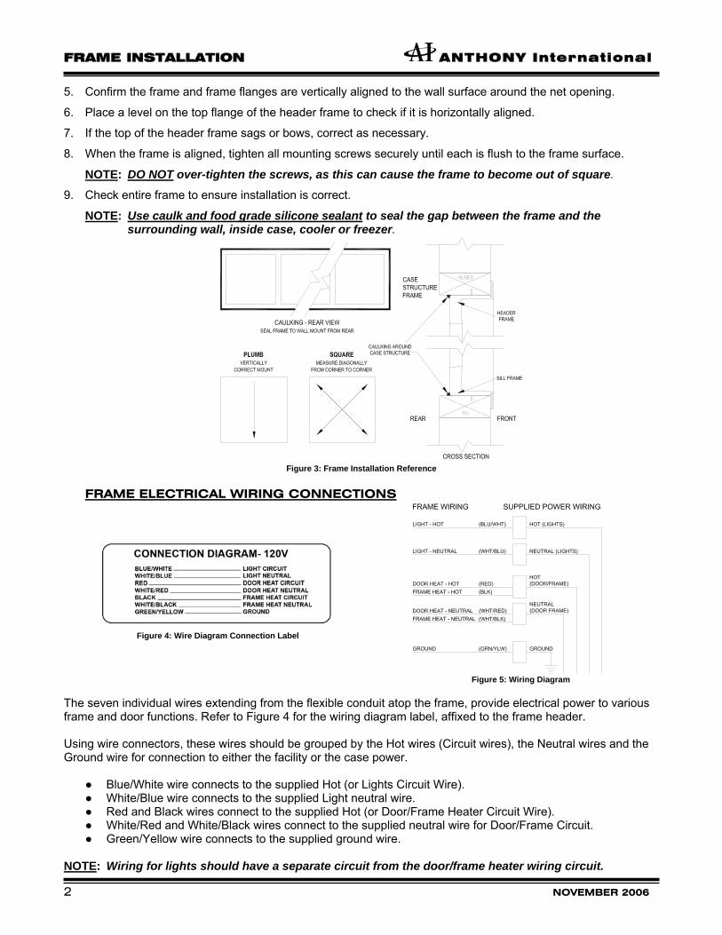
5. Confirm the frame and frame flanges are vertically aligned to the wall surface around the net opening.
6. Place a level on the top flange of the header frame to check if it is horizontally aligned.
7. If the top of the header frame sags or bows, correct as necessary.
8. When the frame is aligned, tighten all mounting screws securely until each is flush to the frame surface.
NOTE: DO NOT over-tighten the screws, as this can cause the frame to become out of square. 9. Check entire frame to ensure installation is correct.
NOTE: Use caulk and food grade silicone sealant to seal the gap between the frame and the surrounding wall, inside case, cooler or freezer.
Figure 3: Frame Installation Reference
FRAME ELECTRICAL WIRING CONNECTIONS
Figure 4: Wire Diagram Connection Label
Figure 5: Wiring Diagram
The seven individual wires extending from the flexible conduit atop the frame, provide electrical power to various frame and door functions. Refer to Figure 4 for the wiring diagram label, affixed to the frame header. Using wire connectors, these wires should be grouped by the Hot wires (Circuit wires), the Neutral wires and the Ground wire for connection to either the facility or the case power.
● Blue/White wire connects to the supplied Hot (or Lights Circuit Wire). ● White/Blue wire connects to the supplied Light neutral wire. ● Red and Black wires connect to the supplied Hot (or Door/Frame Heater Circuit Wire). ● White/Red and White/Black wires connect to the supplied neutral wire for Door/Frame Circuit. ● Green/Yellow wire connects to the supplied ground wire.
NOTE: Wiring for lights should have a separate circuit from the door/frame heater wiring circuit.
ANTHONY International DOOR INSTALLATION
NOVEMBER 2006 3
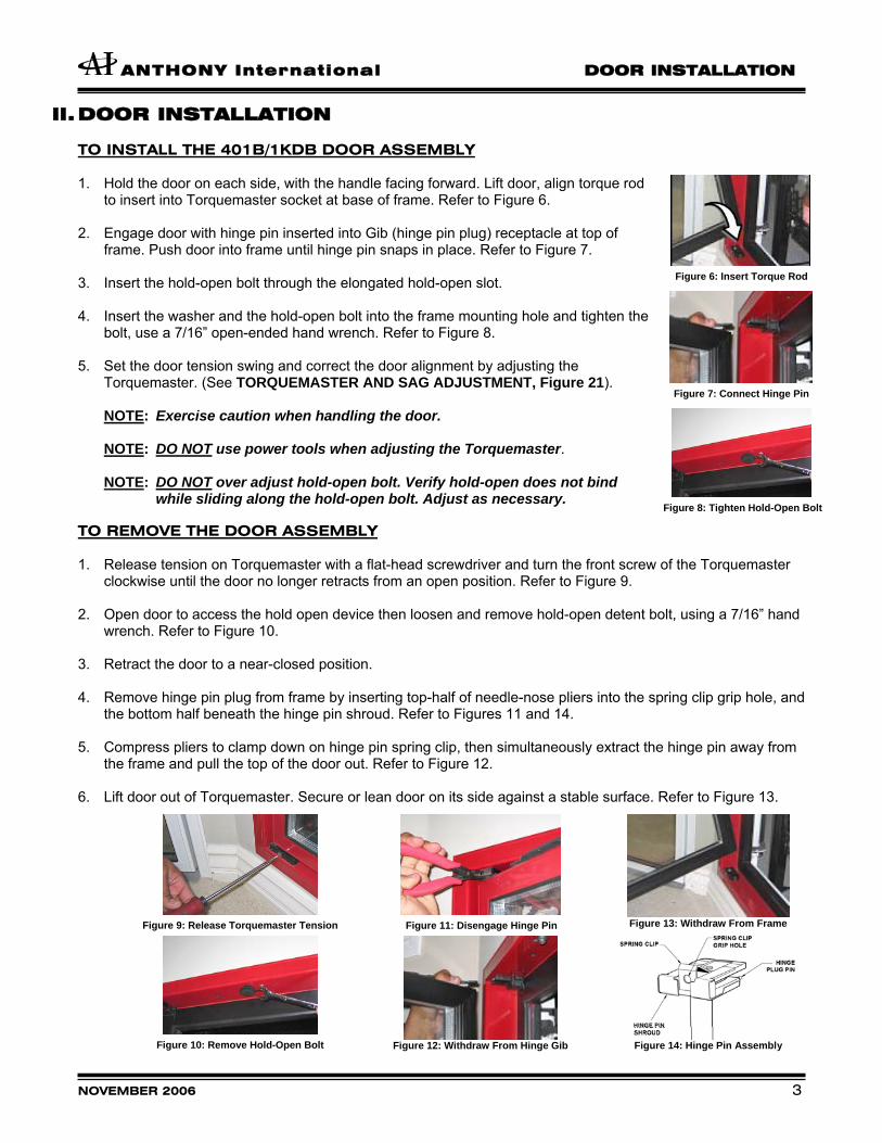
II. DOOR INSTALLATION TO INSTALL THE 401B/1KDB DOOR ASSEMBLY 1. Hold the door on each side, with the handle facing forward. Lift door, align torque rod
to insert into Torquemaster socket at base of frame. Refer to Figure 6. 2. Engage door with hinge pin inserted into Gib (hinge pin plug) receptacle at top of
frame. Push door into frame until hinge pin snaps in place. Refer to Figure 7. 3. Insert the hold-open bolt through the elongated hold-open slot. 4. Insert the washer and the hold-open bolt into the frame mounting hole and tighten the
bolt, use a 7/16” open-ended hand wrench. Refer to Figure 8. 5. Set the door tension swing and correct the door alignment by adjusting the
Torquemaster. (See TORQUEMASTER AND SAG ADJUSTMENT, Figure 21).
NOTE: Exercise caution when handling the door. NOTE: DO NOT use power tools when adjusting the Torquemaster. NOTE: DO NOT over adjust hold-open bolt. Verify hold-open does not bind
while sliding along the hold-open bolt. Adjust as necessary.
Figure 6: Insert Torque Rod
Figure 7: Connect Hinge Pin
Figure 8: Tighten Hold-Open Bolt
TO REMOVE THE DOOR ASSEMBLY
1. Release tension on Torquemaster with a flat-head screwdriver and turn the front screw of the Torquemaster clockwise until the door no longer retracts from an open position. Refer to Figure 9.
2. Open door to access the hold open device then loosen and remove hold-open detent bolt, using a 7/16” hand wrench. Refer to Figure 10.
3. Retract the door to a near-closed position.
4. Remove hinge pin plug from frame by inserting top-half of needle-nose pliers into the spring clip grip hole, and the bottom half beneath the hinge pin shroud. Refer to Figures 11 and 14.
5. Compress pliers to clamp down on hinge pin spring clip, then simultaneously extract the hinge pin away from
the frame and pull the top of the door out. Refer to Figure 12. 6. Lift door out of Torquemaster. Secure or lean door on its side against a stable surface. Refer to Figure 13.
Figure 9: Release Torquemaster Tension
Figure 10: Remove Hold-Open Bolt
Figure 11: Disengage Hinge Pin
Figure 12: Withdraw From Hinge Gib
Figure 13: Withdraw From Frame
Figure 14: Hinge Pin Assembly

DOOR INSTALLATION
ANTHONY International
4 NOVEMBER 2006
TO REVERSE THE DOOR SWING (MODEL 1KDB ONLY) Model 1KDB doors are reversible. Remove the door from the frame first and then perform the following steps. FRAME: 1. To remove Torquemaster, insert flat-head screwdriver
into top center cutout in Torquemaster, and turn mounting screw counter-clockwise for less than ½ turn. Lift Torquemaster off frame. Refer to Figure 15.
2. Pry off (underneath) plug cap from mounting hole, on
opposite side of the doorframe with a flat-head screwdriver. Refer to Figure 16.
3. Set Torquemaster on opened mounting hole. Align the
flanged corners of the mounting tabs with the SAG ADJUSTMENT screw facing the inside of the frame. Refer to Figure 17.
4. Use the flat-head screwdriver and turn the Torquemaster
mounting setscrew clockwise for ½ turn, to tighten the mounting flange and lock it in place.
5. Relocate and install the hold-open stand-offs and spacer
into the opposite hold-open mount of the same doorframe. Refer to Figure 18.
Figure 15: Remove Torquemaster
Figure 16: Remove Plug Cap
Figure 17: Mount Torquemaster
Figure 18: Insert Stand-Off
Figure 19: Hinge Pin Wires
Figure 20: Remove Torque Rod
DOOR:
6. Access the hinge pin wire connections in the rail on the hinge side of the door assembly.
7. Disconnect the Hot, Neutral, and Ground wires of the hinge pin. Refer to Figure 19.
8. Loosen and remove the hinge pin assembly from the top door rail.
9. Using a plastic mallet and a flat-head screwdriver, remove the torque rod from the bottom of the door assembly. Refer to Figure 20.
10. Reinstall the hinge pin and the torque rod into the opposite ends of the door assembly.
11. Reconnect the hinge pin wires and confirm all connections.
12. Check and confirm torque rod and hinge pin are correctly installed.
13. Reinstall the door into the frame per the door installation procedures. TORQUEMASTER AND SAG ADJUSTMENT (MODEL 401B AND 1KDB) The Torquemaster regulates the door alignment and the door closing tension.
1. Use a flathead screwdriver to adjust the torque rod tension, by turning the outside screw on the Torquemaster. ● Turn counter-clockwise to increase tension. ● Turn clockwise to decrease the tension.
2. Adjust the door sag to square it in the frame by turning the screw that is marked SAG ADJ. (sag adjustment), on the end of the Torquemaster, until the door is square in opening. ● Turn counter-clockwise to raise handle side of door. ● Turn clockwise to lower the handle side of door.
NOTE: DO NOT use power tools when adjusting the Torquemaster.
Figure 21: Torquemaster Assembly
ANTHONY International DOOR INSTALLATION
NOVEMBER 2006 5
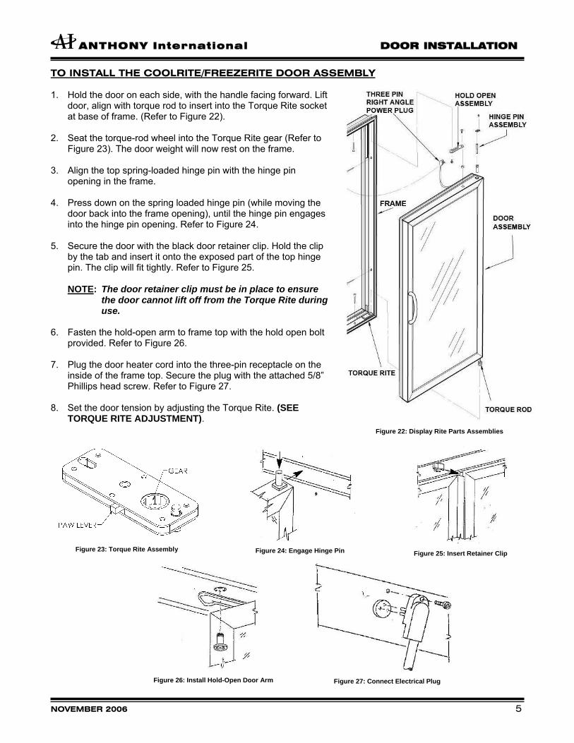
TO INSTALL THE COOLRITE/FREEZERITE DOOR ASSEMBLY 1. Hold the door on each side, with the handle facing forward. Lift
door, align with torque rod to insert into the Torque Rite socket at base of frame. (Refer to Figure 22).
2. Seat the torque-rod wheel into the Torque Rite gear (Refer to
Figure 23). The door weight will now rest on the frame. 3. Align the top spring-loaded hinge pin with the hinge pin
opening in the frame. 4. Press down on the spring loaded hinge pin (while moving the
door back into the frame opening), until the hinge pin engages into the hinge pin opening. Refer to Figure 24.
5. Secure the door with the black door retainer clip. Hold the clip
by the tab and insert it onto the exposed part of the top hinge pin. The clip will fit tightly. Refer to Figure 25.
NOTE: The door retainer clip must be in place to ensure
the door cannot lift off from the Torque Rite during use.
6. Fasten the hold-open arm to frame top with the hold open bolt
provided. Refer to Figure 26. 7. Plug the door heater cord into the three-pin receptacle on the
inside of the frame top. Secure the plug with the attached 5/8” Phillips head screw. Refer to Figure 27.
8. Set the door tension by adjusting the Torque Rite. (SEE
TORQUE RITE ADJUSTMENT). Figure 22: Display Rite Parts Assemblies
Figure 23: Torque Rite Assembly
Figure 24: Engage Hinge Pin
Figure 25: Insert Retainer Clip
Figure 26: Install Hold-Open Door Arm
Figure 27: Connect Electrical Plug

DOOR INSTALLATION
ANTHONY International
6 NOVEMBER 2006
TO REMOVE THE DOOR ASSEMBLY 1. Release tension on Torque Rite prior to removing the door from the frame. Two 1/8” square wire-rods are
necessary. Insert one wire-rod in the Paw Lever opening and one wire-rod in the torque rod adjusting wheel slot. 2. Turn the torque rod adjusting wheel slightly toward the handle to free the Paw Lever, push the second rod
inward, and release wheel in opposite direction. 3. On the door heater cord, unscrew the attached 5/8” Phillips head screw from the frame receptacle and unplug
the cord. 4. Uninstall the bolt securing the hold-open arm from the top frame receptacle. 5. Remove the hinge pin retainer door clip. 6. Push down on the hinge pin and lean door out of the frame opening. 7. Lift door out of Torque Rite. Secure or lean door on its side against a stable surface. TORQUE RITE ADJUSTMENT 1. Use a 1/8” square wire-rod to adjust door-closing tension. Insert one square wire-rod into adjusting slot and turn
torque rod wheel in the direction of the handle, until the door shuts by itself. 4 to 6 clicks maximum. Refer to Figure 28.
2. To release torque tension, insert two 1/8” square wire-rods: one into the Paw Lever opening and one in the
torque rod adjusting wheel slot. With the first rod, turn the adjusting wheel toward Paw Lever and push second rod inward and release wheel in the opposite direction. Refer to Figures 28 and 29.
3. When the door is out of alignment, adjust the Torque Rite sag adjustment screw to the appropriate setting.
Figure 28: Torque Rite Identification Figure 29: Torque Rite Assembly
NOTE: Torque Rite Paw Lever should always face outward. It is used to release tension on the door by
inserting a second 1/8” square rod.
ANTHONY International
COMPANY POLICIES, TERMS OF SALE, AND WARRANTY The following terms and conditions shall apply to all transactions and agreements between Anthony, Inc. (“Anthony”) d/b/a Anthony International and/or Ardco and/or Pike and the other party to such transaction or agreement (“Buyer”) with respect to the purchase of any goods from Anthony and/or the extension of credit by Anthony to Buyer for such purchase. 1. PRICE. Prices shown on the face of the sales invoice are F.O.B. factory, San Fernando, California, packaged for shipment and subject to change without notice. 2. TERMS OF CREDIT. All credit terms are net 30 days from date of invoice. Any deductions from the net invoice amount must be approved by an authorized representative of Anthony. If credit is extended to Buyer, Anthony reserves the right to revoke such credit if Buyer fails to make timely payment for any goods delivered. Anthony reserves the right to require payment or other assurances which it deems necessary prior to the shipment of any goods, if, in Anthony’s opinion, exercised in Anthony’s subjective, good faith judgment, the Buyer’s financial condition has deteriorated or the risk of non-payment has otherwise increased. Credit is subject to approval upon receipt of completed credit application. Any goods shipped prior to credit approval shall be shipped C.O.D., “Cashiers Check,” or pre-payment. A $25.00 charge will be applied for each returned check. Goods may not be returned for credit unless prior authorization and an authorization number have been granted by Anthony. A 1-1/2% per month charge will be assessed on past-due amounts. 3. SHIPMENT OF GOODS / RETURN OF GOODS. Every effort will be made to ship the goods on the scheduled shipment date and to maintain production schedules consistent therewith. Anthony will not be liable, however, for any claims arising from the failure to meet any scheduled shipping dates. If Buyer refuses shipment of any standard catalog products under an acknowledged order and those products are consistent with that order and are not delivered damaged or defective, then Buyer will be responsible for (i) return shipment of the products to Anthony in original shipping containers; (ii) return freight to Anthony prepaid by Buyer; and (iii) a restocking charge to be determined by Anthony not less than twenty-five percent (25%) of the sales price. Buyer assumes the risk of any return shipment damage or loss, the cost of which will be assessed by Anthony and added to the restocking charge. No custom products or custom sizes of catalog items may be returned to Anthony for credit unless those products are not consistent with an acknowledged order or they are defective. If they are defective, Anthony reserves the right to cure the defect at the ship-to location. 4. RISK OF LOSS. Subject to security interests retained by Anthony until payment for the goods is received in full, the title to such goods and risk of loss or damages thereto pass to Buyer upon completion of loading of goods on carrier at Anthony’s factory. Buyer will unload shipments promptly and Buyer will be liable for any additional charges such as demurrage, storage, and labor incurred by its failure to do so. Any claims by Buyer for damages to the goods incurred during shipping shall be made to the carrier. 5. WARRANTIES. Effective November 1, 1997, for Anthony and effective October 1, 2002 for Ardco, the products which Anthony and Ardco manufacture and offer for sale are warranted to: (i) be free from defects in materials and workmanship; and (ii) to perform in accordance with applicable refrigeration standards as of the date of manufacture, provided that the installation and maintenance of such products have been performed strictly in accordance with Anthony specifications, (the “Warranty”) for a period of fifteen 15 months from the date of shipment from Anthony’s San Fernando, California facility (the “Warranty Period”), except that Anthony will provide replacement sealed glass units that are part of an original Anthony-manufactured door if the seal breaks
and internal condensation results for a period of 10 years from the date of Anthony’s shipment. During the 15 month Warranty Period, Anthony shall provide all necessary parts and labor at its cost to provide the Warranty. The extent of Anthony’s liability under the warranty is limited to the repair or replacement, at Anthony’s option, of any non-conforming products without charge, F.O.B. San Fernando, California, until such time as Anthony may change its warranty provisions in its sole discretion at any time or without prior notification of such change. THE ABOVE WARRANTY IS GIVEN IN LIEU OF ALL OTHER WARRANTIES, EXPRESSED OR IMPLIED, INCLUDING ANY IMPLIED WARRANTIES OF MERCHANTABILITY OR FITNESS FOR A PARTICULAR PURPOSE. ANTHONY’S SHALL NOT BE RESPONSIBLE FOR INCIDENTAL OR CONSEQUENTIAL DAMAGES SUCH AS INJURY TO PERSONS OR PROPERTY. 6. CLAIMS BY BUYER. All claims by Buyer against Anthony, including claims for alleged shortages, must be made in writing and delivered to Anthony within 30 days of receipt of the goods. Anthony shall thereupon be afforded a reasonable opportunity to inspect the goods. All claims not made in the time period and manner specified above shall be deemed waived. All actions, claims or defenses by Buyer shall be deemed waived unless commenced or asserted within 6 months of receipt of the goods. 7. CANCELLATION. Orders may not be cancelled after receipt and posting by Anthony unless Anthony consents to such cancellation. Cancellation will be granted only on terms indemnifying us against any loss resulting from such action. At minimum, Buyer will be liable for all cost incurred on the order though the cancellation date. 8. CHANGES BY ANTHONY. Anthony reserves the right to change design, colors and specifications of any goods without notice to Buyer. 9. DEFAULT. If Buyer defaults on the purchase of any goods or if a petition in bankruptcy is filed by or against Buyer, Anthony, in addition to other remedies, may repossess any goods which were previously delivered and for which payment has not been received and may refuse to make further shipment of goods. Buyer agrees to pay Anthony’s costs and expenses of collection or repossession including the maximum attorney’s fee permitted by law. 10. ENTIRE AGREEMENT AND AMENDMENT. The terms specified herein constitute the entire agreement between Anthony and Buyer with respect to the sale and purchase of the goods and any extension of credit. If Anthony and Buyer agree to amend or modify any terms and conditions specified herein, such amendment or modification must be expressly stated on the face of the sales invoice or by a written agreement duly executed by both parties. The terms specified herein shall control in the event of any variance between these terms and any terms contained in Buyer’s purchase orders. 11. GOVERNING LAW. Agreements between Anthony and Buyer with respect to the sale and purchase of the goods and any extension of credit shall be governed by, construed and enforced in accordance with the laws of the State of California, County of Los Angeles. By entering into any agreement with Anthony, Buyer consents to the jurisdiction of the courts of the State of California. Service of process may be made by registered mail promptly addressed to the Buyer. 12. SERVABILITY. If any provision of the terms and conditions specified herein shall be deemed invalid or unenforceable, the remaining terms and conditions shall be construed as though such provision does not appear herein and shall be otherwise fully enforceable. 13. HEADINGS. The section headings contained herein have been inserted for convenient reference and shall not be considered in any question of interpretation or construction of any agreements between Anthony and Buyer.
Anthony products are covered by one or more of the following United States Patents: 4,004,370; 4,035,608; 4,080,756; 4,087,139; 4,127,188; 4,127,765; 4,221,443, 4,248,015; 4,260,876; 4,265,069; 4,306,140; 4,382,177; 4,477,129; 4,671,582; 4,696,078; 4,760,621; 4,905,347; 5,002,320; 5,097,642; 5,113,628; 5,251,402; 5,284,371; 5,297,863; 5,299,437; 5,301,092; 5,309,066; 5,315,211; 5,363,611; 5,544,454; 5,720,540; 5,879,070; 5,895,111; 5,910,083; 6,029,411; 6,031,338; 5,902,034; 5,959,816; 6,010,227; 6,122,869; 6,222,322; 6,260,255; 6,298,615; 6,302,306; 6,302,557; 6,318,027; 6,325,523; 6,367,223; 6,389,993; 6,490,983; 6,343,405; D332,564; Re. 35,120; Re. 35,149; Re. 35,392; 5,605,237; 2,987,782; 3,131,421; 3,295,634; 3,345,606; 3,399,784; 3,449,551; 3,475,594; 3,499,245; 3,508,361; 3,526,753; 3,629,972; 3,673,735; 3,696,360; 3,697,723; 3,837,119; 4,145,844; 4,261,179; 4,416,086; 4,428,096; 4,430,770; 4,641,461; 4,656,781; 4,691,486; 4,741,127; 4,753,043; 4,831,780; 4,852,303; 4,941,289; 4,998,382; 5,016,146; 5,024,023; 5,035,085; 5,116,274; 5,207,490; 5,214,877; 5,244,273; 5,255,473; 5,333,355; 5,111,618; 5,471,372; 5,622,414; 5,645,330; 5,116,274; 5,207,490; 5,622,414; 4,691,486; 6,632,100; 6,637,093, 6,638,088. Corresponding Foreign Patents Issued and Pending. Other United States and Foreign Patents Pending.
(10/05)

ANTHONY International Providing Merchandising Systems to the World 12391 Montero Avenue, Sylmar, CA 91342 Ph: 1-800-772-0900 Fax: 1-818-361-9611 http://www.anthonydoors.com http://www.ardcodoors.com Part No. 99-16379-S001 Revision A

Related Documents