AJAL.A.J- AP ECE UNIVERSAL ENGG COLLEGE RADIATION & PROPOGATION RADIATION & PROPOGATION - - Fundamental Parameters of Antennas Fundamental Parameters of Antennas AJAL.A.J Assistant Professor –Dept of ECE, UNIVERSAL ENGINEERING COLLEGE Mob: 8907305642 MAIL: [email protected]

Antenna PARAMETERS
Nov 15, 2014
Antenna PARAMETERS
Welcome message from author
This document is posted to help you gain knowledge. Please leave a comment to let me know what you think about it! Share it to your friends and learn new things together.
Transcript
AJAL.A.J- AP ECE UNIVERSAL ENGG COLLEGE
RADIATION & PROPOGATIONRADIATION & PROPOGATION--Fundamental Parameters of AntennasFundamental Parameters of Antennas
AJAL.A.J Assistant Professor –Dept of ECE,
UNIVERSAL ENGINEERING COLLEGE
Mob: 8907305642 MAIL: [email protected]
AJAL.A.J- AP ECE UNIVERSAL ENGG COLLEGE
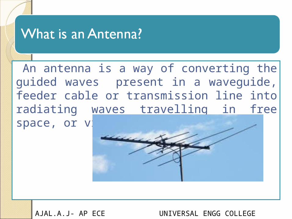
An antenna is a way of converting the guided waves present in a waveguide, feeder cable or transmission line into radiating waves travelling in free space, or vice versa.
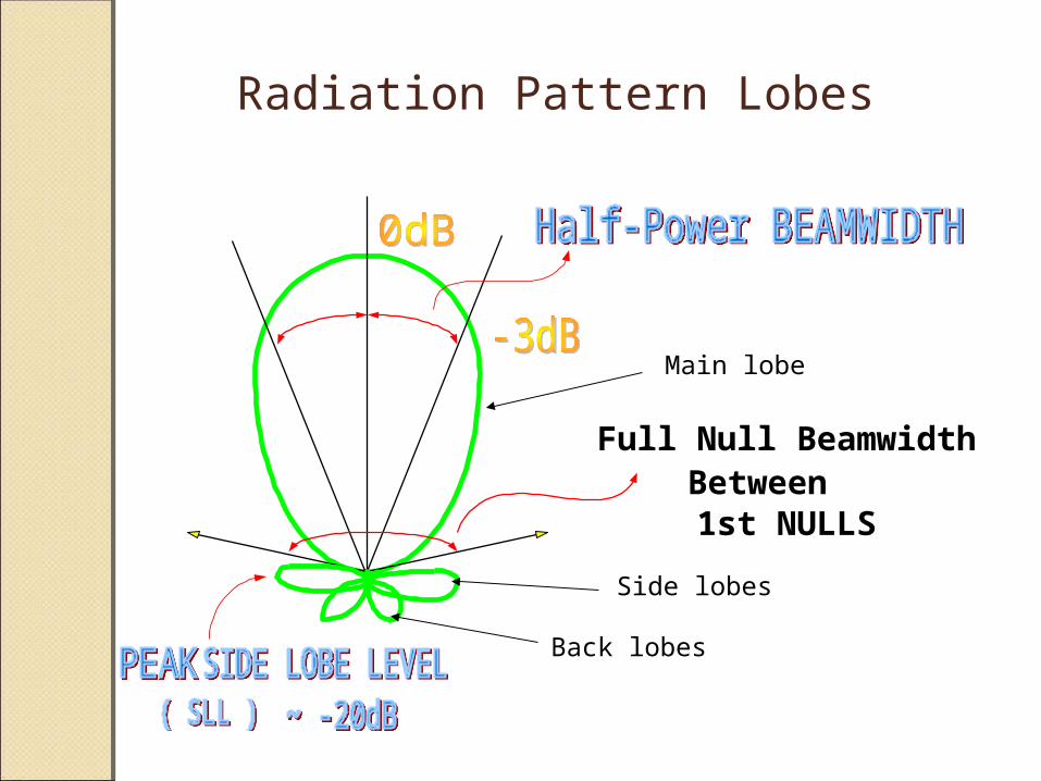
Full Null BeamwidthBetween1st NULLS
Radiation Pattern Lobes
Main lobe
Side lobes
Back lobes
AJAL.A.J- AP ECE UNIVERSAL ENGG COLLEGE
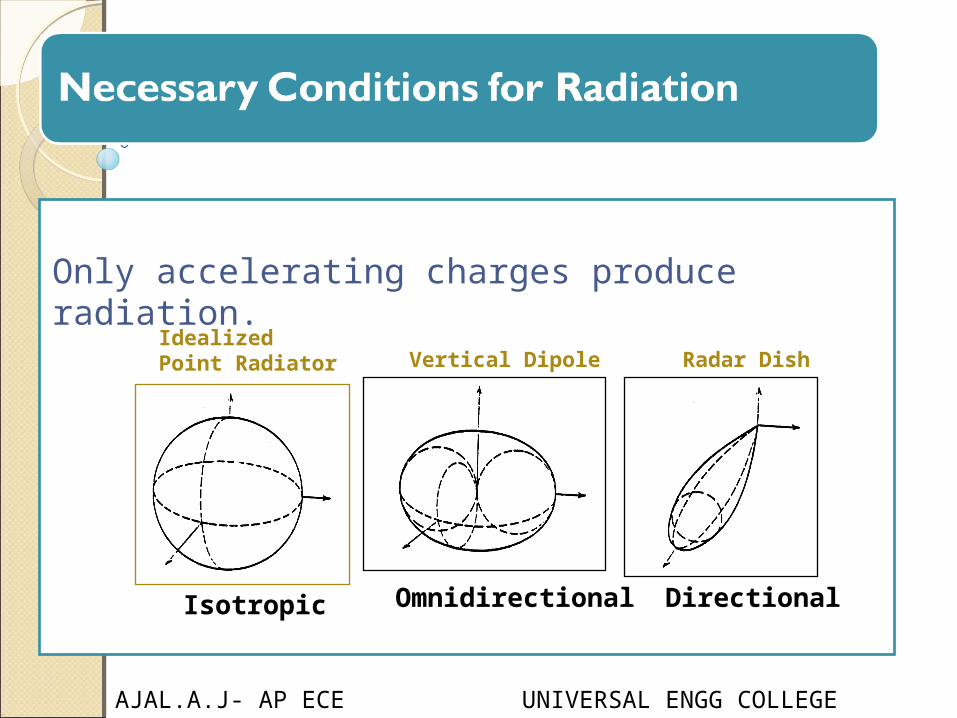
Only accelerating charges produce radiation.
IdealizedPoint Radiator Vertical Dipole Radar Dish
Isotropic Omnidirectional Directional

AJAL.A.J- AP ECE UNIVERSAL ENGG COLLEGE
Two fields regions:oNear field or Fresnel region: The region within the radius of the smallest sphere which completely encloses the antenna is called Fresnel region.In sitting an antenna ,it’s crucial to keep objects out of the near field region to avoid coupling the currents in the antenna with objects.
oFar Field or Fraunhofer region: The region beyond Fresnel region is called Fraunhofer region

AJAL.A.J- AP ECE UNIVERSAL ENGG COLLEGE
Antenna parameters are: 1.Radiation Pattern
2.Directivity
3.Radiation Resistance and Efficiency
4.Power Gain
5.Bandwidth
6.Reciprocity
7.Effective Aperture
8.Beamwidth and Directivity
9.The Friis Formula: Antennas in Free Space
10.Polarisation Matching
AJAL.A.J- AP ECE UNIVERSAL ENGG COLLEGE
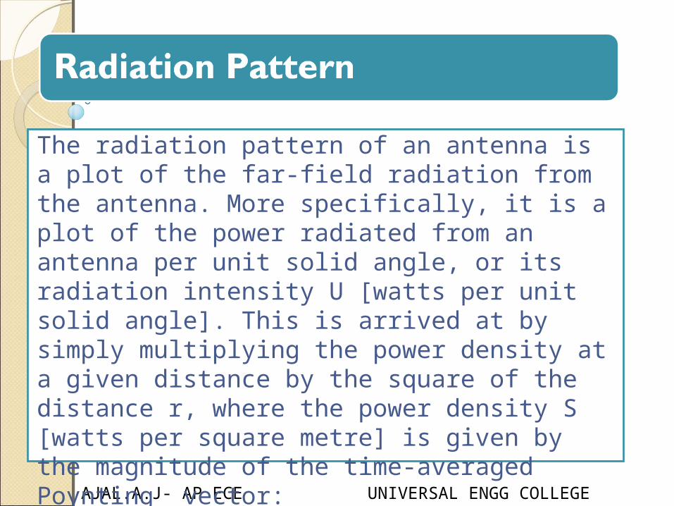
The radiation pattern of an antenna is a plot of the far-field radiation from the antenna. More specifically, it is a plot of the power radiated from an antenna per unit solid angle, or its radiation intensity U [watts per unit solid angle]. This is arrived at by simply multiplying the power density at a given distance by the square of the distance r, where the power density S [watts per square metre] is given by the magnitude of the time-averaged Poynting vector: U=r^²S
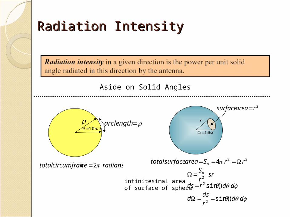
Radiation IntensityRadiation Intensity
Aside on Solid Angles
lengtharcrad0.1
r
sr0.1
2rareasurface
radianscecircumfrantotal 2224 rrSareasurfacetotal o
srr
So2
ddrds )sin(2infinitesimal areaof surface of sphere
ddr
dsd )sin(
2
AJAL.A.J- AP ECE UNIVERSAL ENGG COLLEGE
Antenna parameters are: 1.Radiation Pattern
2.Directivity
3.Radiation Resistance and Efficiency
4.Power Gain
5.Bandwidth
6.Reciprocity
7.Effective Aperture
8.Beamwidth and Directivity
9.The Friis Formula: Antennas in Free Space
10.Polarisation Matching

AJAL.A.J- AP ECE UNIVERSAL ENGG COLLEGE
The directivity D of an antenna, a function of directionis defined by the ratio of radiation intensity of antenna in direction to the mean radiation intensity in all directions.

AJAL.A.J- AP ECE UNIVERSAL ENGG COLLEGE
Antenna parameters are: 1.Radiation Pattern
2.Directivity
3.Radiation Resistance and Efficiency
4.Power Gain
5.Bandwidth
6.Reciprocity
7.Effective Aperture
8.Beamwidth and Directivity
9.The Friis Formula: Antennas in Free Space
10.Polarisation Matching
AJAL.A.J- AP ECE UNIVERSAL ENGG COLLEGE
The resistive part of the antenna impedance is split into two parts, a radiation resistance Rr and a loss resistance Rl. The power dissipated in the radiation resistance is the power actually radiated by the antenna, and the loss resistance is power lost within the antenna itself. This may be due to losses in either the conducting or the dielectric parts of the antenna. Radiation efficiency e of the antenna as e is the ratio of power radiated to the power accepted by antenna
antenna with high radiation efficiency therefore has high associated radiation resistance compared with the losses. The antenna is said to be resonant if its input reactance Xa =0.

AJAL.A.J- AP ECE UNIVERSAL ENGG COLLEGE
Antenna parameters are: 1.Radiation Pattern
2.Directivity
3.Radiation Resistance and Efficiency
4.Power Gain
5.Bandwidth
6.Reciprocity
7.Effective Aperture
8.Beamwidth and Directivity
9.The Friis Formula: Antennas in Free Space
10.Polarisation Matching

AJAL.A.J- AP ECE UNIVERSAL ENGG COLLEGE
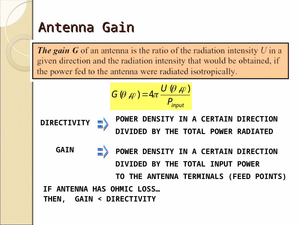
The power gain G, or simply the gain, of an antenna is the ratio of its radiation intensity to thatof an isotropic antenna radiating the same total power as accepted by the real antenna. Whenantenna manufacturers specify simply the gain of an antenna they are usually referring to themaximum value of G.
Antenna GainAntenna Gain
inputP
UG
),(4),(
POWER DENSITY IN A CERTAIN DIRECTION
DIVIDED BY THE TOTAL POWER RADIATED
POWER DENSITY IN A CERTAIN DIRECTION
DIVIDED BY THE TOTAL INPUT POWER
TO THE ANTENNA TERMINALS (FEED POINTS)
IF ANTENNA HAS OHMIC LOSS…THEN, GAIN < DIRECTIVITY
DIRECTIVITY
GAIN
AJAL.A.J- AP ECE UNIVERSAL ENGG COLLEGE
Antenna parameters are: 1.Radiation Pattern
2.Directivity
3.Radiation Resistance and Efficiency
4.Power Gain
5.Bandwidth
6.Reciprocity
7.Effective Aperture
8.Beamwidth and Directivity
9.The Friis Formula: Antennas in Free Space
10.Polarisation Matching
AJAL.A.J- AP ECE UNIVERSAL ENGG COLLEGE
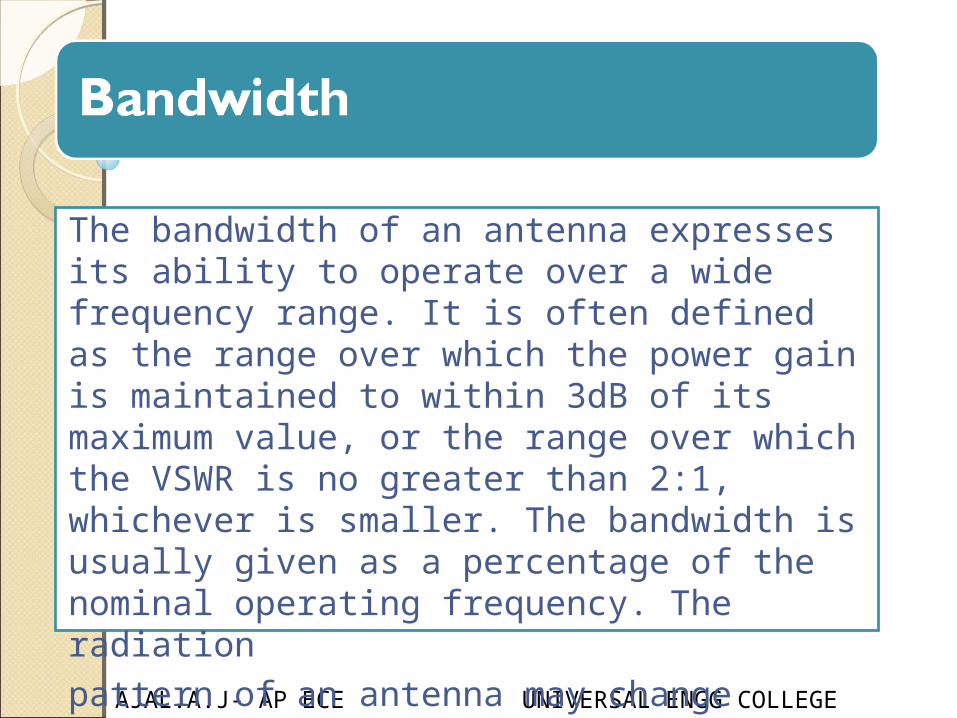
The bandwidth of an antenna expresses its ability to operate over a wide frequency range. It is often defined as the range over which the power gain is maintained to within 3dB of its maximum value, or the range over which the VSWR is no greater than 2:1, whichever is smaller. The bandwidth is usually given as a percentage of the nominal operating frequency. The radiationpattern of an antenna may change dramatically outside its specified operating bandwidth.

AJAL.A.J- AP ECE UNIVERSAL ENGG COLLEGE
Antenna parameters are: 1.Radiation Pattern
2.Directivity
3.Radiation Resistance and Efficiency
4.Power Gain
5.Bandwidth
6.Reciprocity
7.Effective Aperture
8.Beamwidth and Directivity
9.The Friis Formula: Antennas in Free Space
10.Polarisation Matching
AJAL.A.J- AP ECE UNIVERSAL ENGG COLLEGE
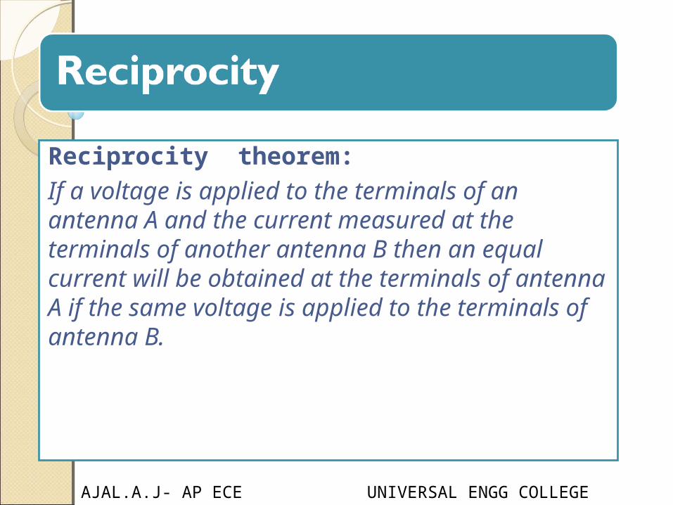
Reciprocity theorem:If a voltage is applied to the terminals of an antenna A and the current measured at the terminals of another antenna B then an equal current will be obtained at the terminals of antenna A if the same voltage is applied to the terminals of antenna B.
AJAL.A.J- AP ECE UNIVERSAL ENGG COLLEGE
Antenna parameters are: 1.Radiation Pattern
2.Directivity
3.Radiation Resistance and Efficiency
4.Power Gain
5.Bandwidth
6.Reciprocity
7.Effective Aperture
8.Beamwidth and Directivity
9.The Friis Formula: Antennas in Free Space
10.Polarisation Matching
AJAL.A.J- AP ECE UNIVERSAL ENGG COLLEGE
Effective ApertureEffective Aperture
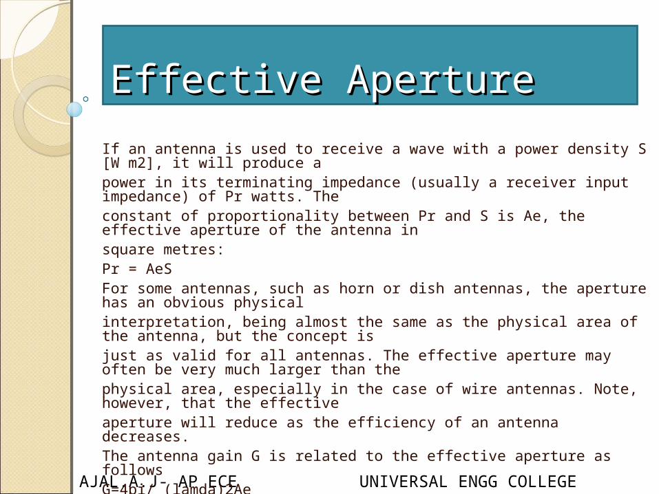
If an antenna is used to receive a wave with a power density S [W m2], it will produce apower in its terminating impedance (usually a receiver input impedance) of Pr watts. Theconstant of proportionality between Pr and S is Ae, the effective aperture of the antenna insquare metres:Pr = AeS For some antennas, such as horn or dish antennas, the aperture has an obvious physicalinterpretation, being almost the same as the physical area of the antenna, but the concept isjust as valid for all antennas. The effective aperture may often be very much larger than thephysical area, especially in the case of wire antennas. Note, however, that the effectiveaperture will reduce as the efficiency of an antenna decreases.The antenna gain G is related to the effective aperture as follows G=4pi/ (lamda)2Ae
Effective ApertureEffective Aperture
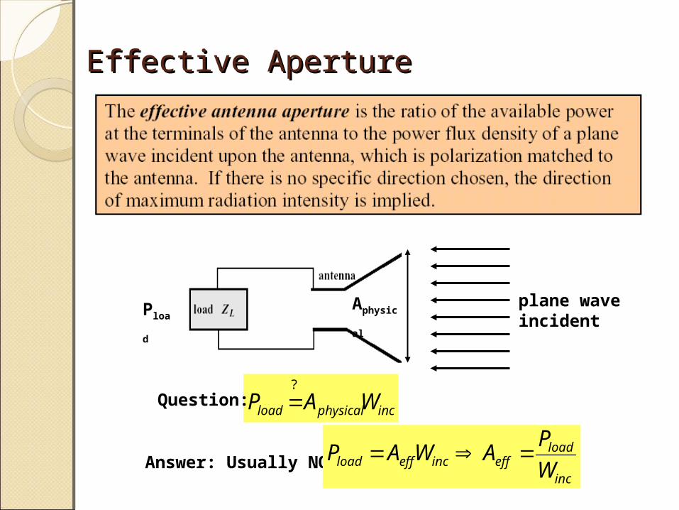
plane waveincident
AphysicalPload
incphysicalload WAP?
Question:
Answer: Usually NOTinc
loadeffinceffload W
PAWAP
AJAL.A.J- AP ECE UNIVERSAL ENGG COLLEGE
Antenna parameters are: 1.Radiation Pattern
2.Directivity
3.Radiation Resistance and Efficiency
4.Power Gain
5.Bandwidth
6.Reciprocity
7.Effective Aperture
8.Beamwidth and Directivity
9.The Friis Formula: Antennas in Free Space
10.Polarisation Matching
AJAL.A.J- AP ECE UNIVERSAL ENGG COLLEGE
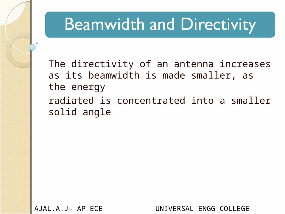
The directivity of an antenna increases as its beamwidth is made smaller, as the energyradiated is concentrated into a smaller solid angle

AJAL.A.J- AP ECE UNIVERSAL ENGG COLLEGE
Antenna parameters are: 1.Radiation Pattern
2.Directivity
3.Radiation Resistance and Efficiency
4.Power Gain
5.Bandwidth
6.Reciprocity
7.Effective Aperture
8.Beamwidth and Directivity
9.The Friis Formula: Antennas in Free Space
10.Polarisation Matching
AJAL.A.J- AP ECE UNIVERSAL ENGG COLLEGE
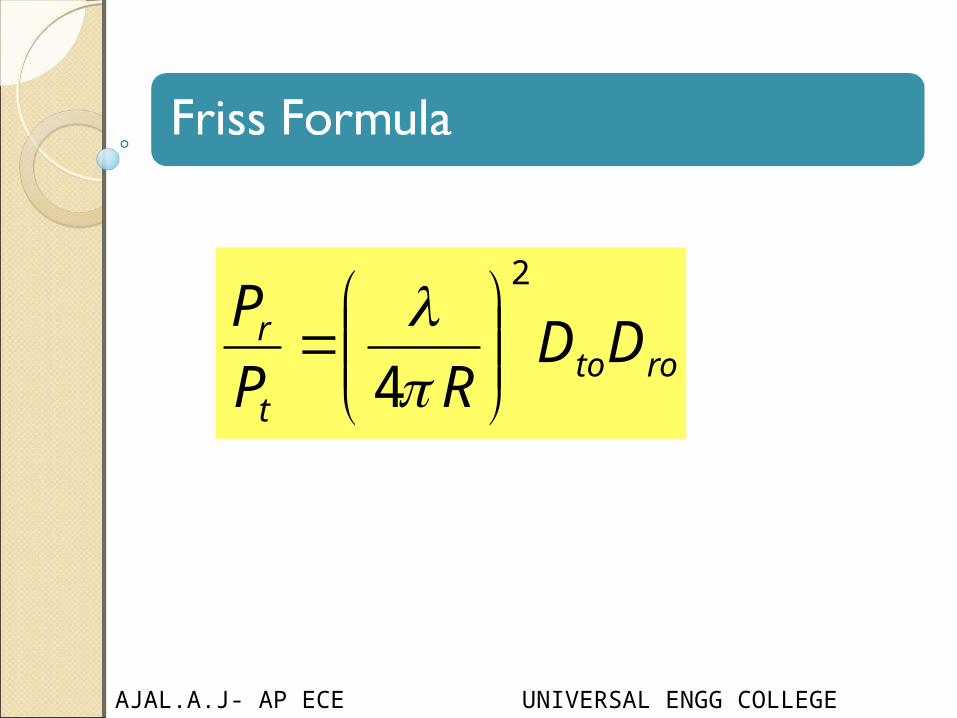
rotot
r DDRP
P2
4
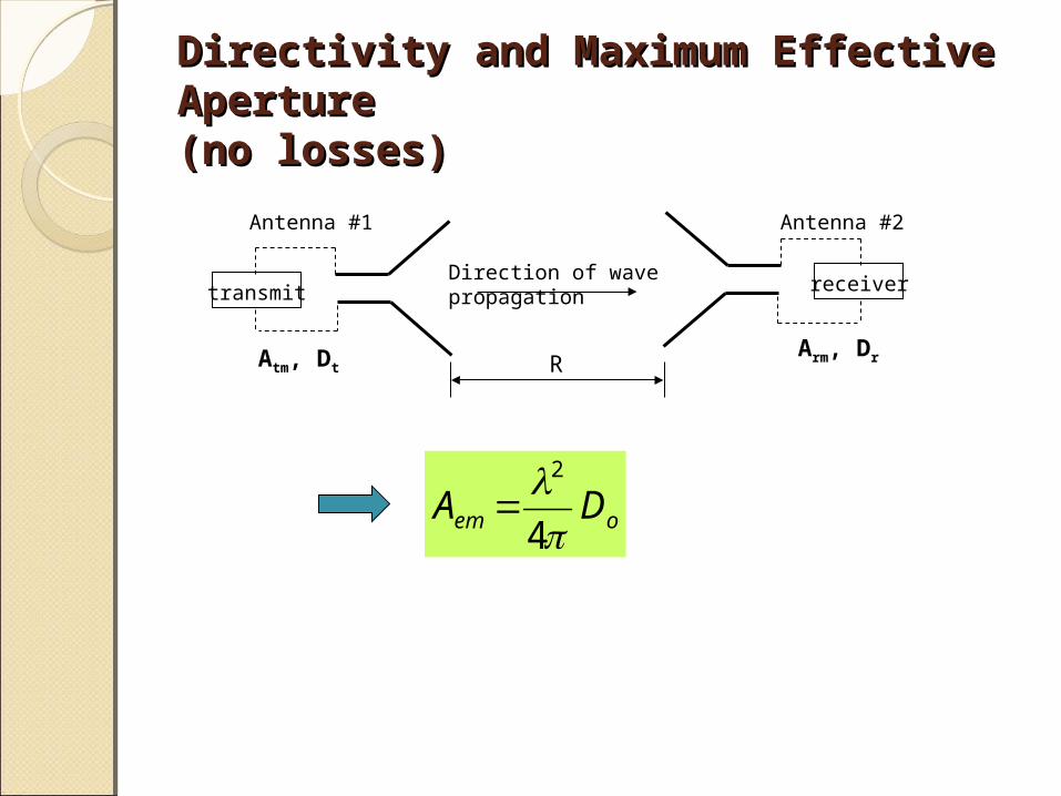
Directivity and Maximum Effective Aperture Directivity and Maximum Effective Aperture (no losses)(no losses)
Antenna #2
transmit receiver
R
Direction of wave propagation
Antenna #1
Atm, DtArm, Dr
oem DA4
2
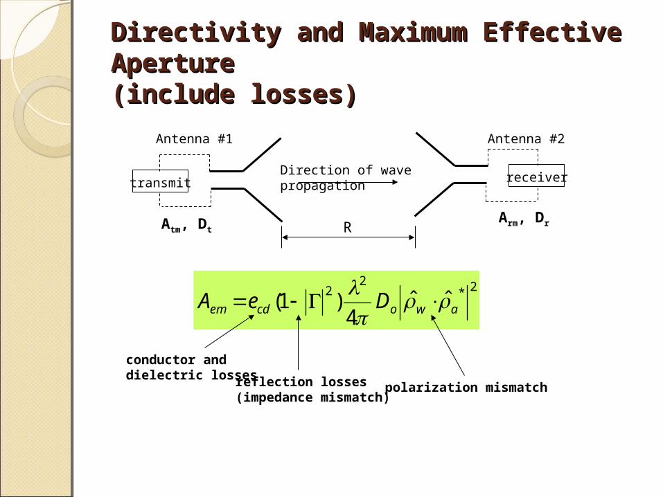
Directivity and Maximum Effective Aperture Directivity and Maximum Effective Aperture (include losses)(include losses)
Antenna #2
transmit receiver
R
Direction of wave propagation
Antenna #1
Atm, DtArm, Dr
2*2
2 ˆˆ4
)1( awocdem DeA
conductor and dielectric losses reflection losses
(impedance mismatch)polarization mismatch
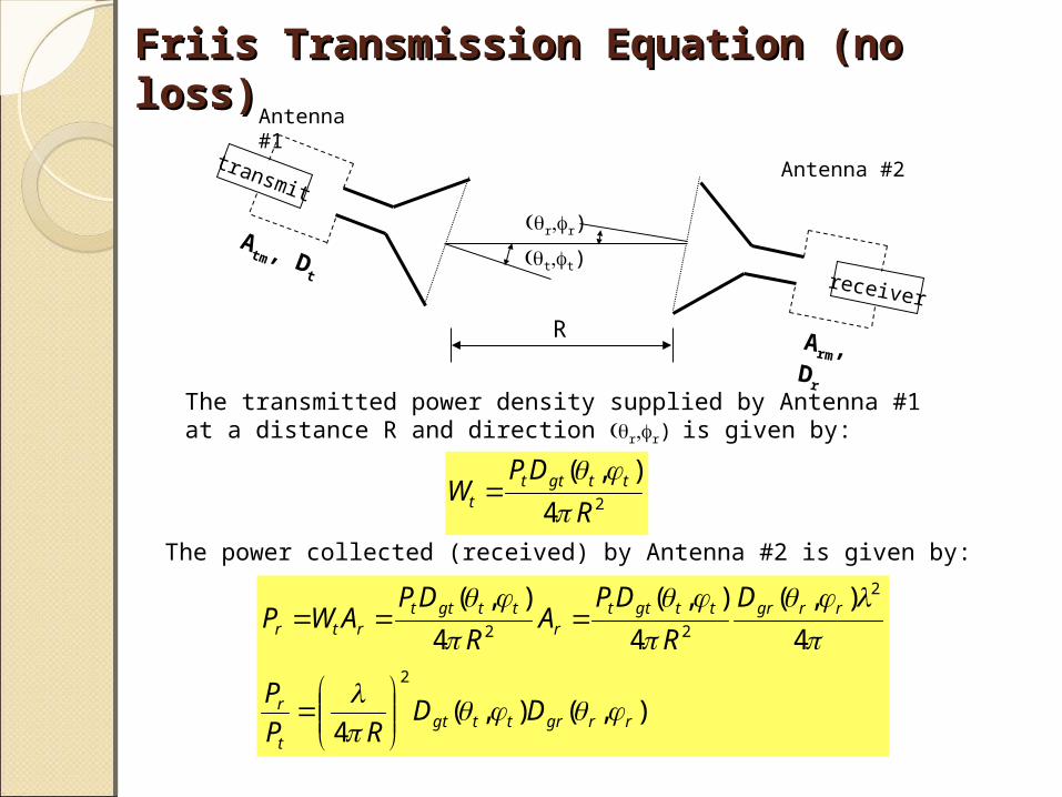
Friis Transmission Equation (no loss)Friis Transmission Equation (no loss)
Antenna #2
Antenna #1
R
transmit
Atm , D
treceiver
Arm, D
r
The transmitted power density supplied by Antenna #1at a distance R and direction rr)is given by:
24
),(
R
DPW ttgttt
tt)
rr)
The power collected (received) by Antenna #2 is given by:
),(),(4
4
),(
4
),(
4
),(
2
2
22
rrgrttgtt
r
rrgrttgttr
ttgttrtr
DDRP
P
D
R
DPA
R
DPAWP

Friis Transmission Equation (no loss)Friis Transmission Equation (no loss)
Antenna #2
Antenna #1
R
transmit
Atm , D
treceiver
Arm, D
r
tt)
rr)
),(),(4
2
rrgrttgtt
r DDRP
P
If both antennas are pointing in the direction of their maximum radiation pattern:
rotot
r DDRP
P2
4
AJAL.A.J- AP ECE UNIVERSAL ENGG COLLEGE
Antenna parameters are: 1.Radiation Pattern
2.Directivity
3.Radiation Resistance and Efficiency
4.Power Gain
5.Bandwidth
6.Reciprocity
7.Effective Aperture
8.Beamwidth and Directivity
9.The Friis Formula: Antennas in Free Space
10.Polarisation Matching
AJAL.A.J- AP ECE UNIVERSAL ENGG COLLEGE
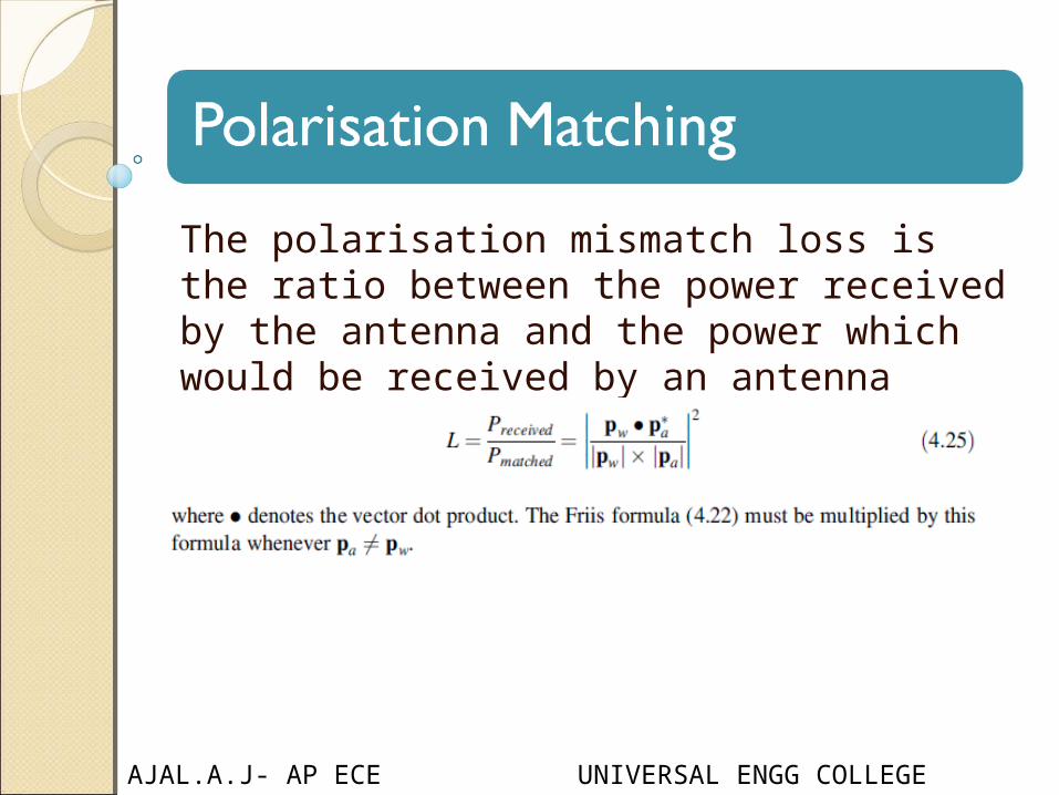
The polarisation mismatch loss is the ratio between the power received by the antenna and the power which would be received by an antenna perfectly matched to the incident wave

AppendicesAppendices
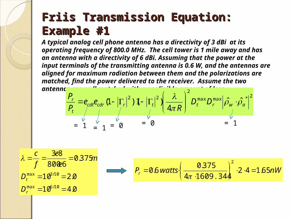
Friis Transmission Equation: Example #1Friis Transmission Equation: Example #1
A typical analog cell phone antenna has a directivity of 3 dBi at its operating frequency of 800.0 MHz. The cell tower is 1 mile away and has an antenna with a directivity of 6 dBi. Assuming that the power at the input terminals of the transmitting antenna is 0.6 W, and the antennas are aligned for maximum radiation between them and the polarizations are matched, find the power delivered to the receiver. Assume the two antennas are well matched with a negligible amount of loss.
nWwattsPr 65.142 609.344 14
375.06.0
2
2*maxmax
222 ˆˆ
4)1)(1( awrttrcdrcdt
t
r DDR
eeP
P
= 0 = 0= 1= 1 = 1
0.410
0.210
375.06800
83
10/6max
10/3max
r
t
D
D
me
e
f
c
Friis Transmission Equation: Example #2Friis Transmission Equation: Example #2
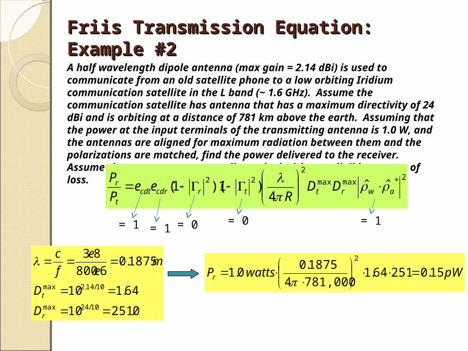
A half wavelength dipole antenna (max gain = 2.14 dBi) is used to communicate from an old satellite phone to a low orbiting Iridium communication satellite in the L band (~ 1.6 GHz). Assume the communication satellite has antenna that has a maximum directivity of 24 dBi and is orbiting at a distance of 781 km above the earth. Assuming that the power at the input terminals of the transmitting antenna is 1.0 W, and the antennas are aligned for maximum radiation between them and the polarizations are matched, find the power delivered to the receiver. Assume the two antennas are well matched with a negligible amount of loss.
pWwattsPr 15.025164.1 781,0004
1875.00.1
2
2*maxmax
222 ˆˆ
4)1)(1( awrttrcdrcdt
t
r DDR
eeP
P
= 0 = 0= 1= 1 = 1
0.25110
64.110
1875.06800
83
10/24max
10/14.2max
r
t
D
D
me
e
f
c
Friis Transmission Equation: Example #2Friis Transmission Equation: Example #2
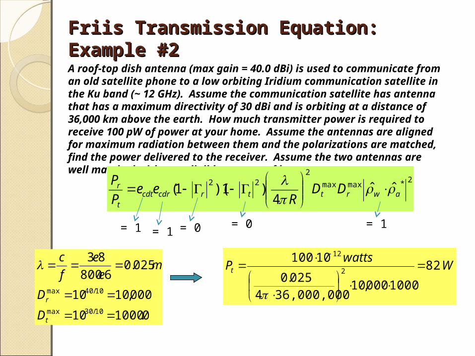
A roof-top dish antenna (max gain = 40.0 dBi) is used to communicate from an old satellite phone to a low orbiting Iridium communication satellite in the Ku band (~ 12 GHz). Assume the communication satellite has antenna that has a maximum directivity of 30 dBi and is orbiting at a distance of 36,000 km above the earth. How much transmitter power is required to receive 100 pW of power at your home. Assume the antennas are aligned for maximum radiation between them and the polarizations are matched, find the power delivered to the receiver. Assume the two antennas are well matched with a negligible amount of loss.
Wwatts
Pt 82
1000000,10 36,000,0004
025.0
101002
12
2*maxmax
222 ˆˆ
4)1)(1( awrttrcdrcdt
t
r DDR
eeP
P
= 0 = 0= 1= 1 = 1
0.100010
000,1010
025.06800
83
10/30max
10/40max
t
r
D
D
me
e
f
c
Related Documents


![Design of Wide Band Patch Antenna with DGS L StructureDesign parameters are calculated using the equations given by C. A. Balanis, Antenna Theory [1]. The essential parameters for](https://static.cupdf.com/doc/110x72/5e893a7a13f46577fe591e30/design-of-wide-band-patch-antenna-with-dgs-l-structure-design-parameters-are-calculated.jpg)