ANTARES ® Gas insulated switchgear up to 24 kV

Welcome message from author
This document is posted to help you gain knowledge. Please leave a comment to let me know what you think about it! Share it to your friends and learn new things together.
Transcript
ANTARES®
Gas insulated switchgear up to 24 kV
Non
bin
ding
doc
umen
t 01/
16 -
Réa
lisat
ion
: L. B
onho
mm
e.

2
Sales documentation can be sent to you on request
CONNECTING ENERGY AND PEOPLE... throughout the world

3
CAHORS: an expert in energy distribution networks.CAHORS designs, manufactures and markets solutions and equipment dedicated to public and private electricity distribution networks.
Innovation is the fundamental energy at Cahors.Innovation in developing new products, in our manufacturing processes, in our management and working methods. Cahors is firmly on the road to sustainable development, and supports the Global Compact.
Cahors is a key player in the development of Smart Grids for almost 30 years. It offers a wide range of connected solutions tailored to your needs and requirements.
• Solutions for Medium Voltage Networks CAHORS offers comprehensive solutions, equipment and services suited to the specificities of Medium Voltage electricity distribution networks, all around the world. Our complementary business units and skills, combined with technological expertise enable us to develop substations integrating transformers, Medium Voltage switchgears, Low Voltage boards, high tech electronics, and even remote network monitoring.
• Solutions for Low Voltage Networks CAHORS develops a range of solutions tailored to all needs: connection, metering, distribution and protection. Our products ranges can be adapted to the requirements of any type of location: underground connections, street lighting units, cabinets, floor distribution panels and electric charging stations.
• Solutions for Communication Networks CAHORS innovates in connecting and communicating data. Our connectors, terminals and casings can be placed on all telecom networks. CAHORS deploys a whole range of solutions, in electronics, analogical and digital: IPTV, copper networks, optic fibre and civil engineering.
• Distribution of fluids CAHORS helps to develop drinking water and gas distribution networks on all five continents. Our units, underground modules and comprehensive connecting solutions combine efficiency and environmental integration. Our expertise in electronics has led to remote readings of fluid meters.
CAHORS, a worldwide commercial and industrial presence !
Industrial sites and sales offices
Sales offices / Distributors / Trading partners
CONNECTING ENERGY AND PEOPLE... throughout the world
Already present on four continents, CAHORS keeps adapting its industrial and commercial capacities to match the needs of regional and global markets. Its various industrial facilities around the world allow significant research and manufacturing capacities. Each site can manufacture small and large production runs and answers specific orders with the greatest reactivity. The sales team at CAHORS maintains an ongoing dialogue with their customers in Europe, Africa, Asia and the Americas and offers them complete solutions to suit their needs.
4
General contents1 // Switchboard PreSentation - Introduction- Standards & quality- Switchboard Product description
2 // antareS®, ranGe of functional unitS- Introduction- Range of functions- Switchboard available configuration- Overall dimensions
3 // Switchboard uSe- User interface - Interlocks, padlocking and security locks- Extensibility- Cable compartment- Top & Side cable attachment- Fuses compartment- Cable testing
4 // characteriSticS - AI, IFC, IFA, DPT, LD and AD functions- Choice of mechanisms and equipment
5// acceSSorieS and oPtionS- Fuses and selection of Medium Voltage fuses- Low voltage equipment- Remote control- Accessories
6 // inStallation - Selection of cables and separable connectors- Overall dimensions drawings- Indoor installation- Evacuation of overpressure- Switchboard packaging and transport
7// antareS® and SuStainable environment- Sustainable development- End of the ANTARES switchboard service life- SF6 gas recovering
8 // medium voltaGe ServiceS
4
5
Switchboard PreSentation
Switchboard uSe
acceSSorieS and oPtionS
antareS® and SuStainable
environment
inStallation
medium voltaGeServiceS
antareS®, ranGe of functional unitS
characteriSticS
1
2
3
4
5
6
8
7

6
SwITCHbOARd PRESEnTATIOnantareS, Safe, comPact, and free-maintenance switchboardaNtarEs is a medium voltage secondary distribution switchboard up to 24 kV, 630 a, 25 ka-1s, used in applications such as public distribution, renewable energies, infrastructure and industry.the switchboard extensibility, the wide range of unit functions, the compactness and the ease of installation can fit with various switchboard requirements. both Fuses and Vacuum circuit breaker (Vcb) transformer protection technologies are available and can be fitted in aNtarEs switchboard.
GiS, electrically inSulatedSwitchboard by sF6 Gas the medium-voltage main circuit of the aNtarEs switchboard, such as vacuum circuit breaker, load break Switch and busbar are placed in Sf6 insulating gas (sulphur hexafluoride - sF6). the sF6 gas acts as insulating and arc extinguishing medium for very compact solution. stainless steel tank confines the primary circuit in a hermetically sealed environment and give the insensibility to the outside environment (Vermin, humidity, dust, Pollution).
switchboard SAFETY aNtarEs is fully type tested and has been designed for maximum safety of the operators and equipment, specifically in case of internal arcing in the equipment:- safety valves to avoid gas overpressure
and non-guided projection- Guidance at the rear to direct the hot gases- Front and side protection for the operator.
inStallation facility, a Priority For aNtarEs switchboardaNtarEs functional units are ultra-light, ultra-compact, thanks to design orientation and sF6 gas technology. For instance, the footprint on the floor for a switchboard with 3 functional units is minimized at 842 mm x 1125 mm and average mass of 230 kg for 3 ways unit.the switchboard extension facilities give the opportunity to assemble into a complete switchboard, functional unit by functional unit, with narrow installation access.then, the installation of aNtarEs is very easy whatever its installation location: compact Sub-Station, underground or on upper floors.
maintenance FrEE dEsiGN - Maintenance free & service life of 40 years
for the primary circuit with no gas filling during the service life.
- simplified maintenance on other parts of the functional units, thanks to long experience, customer feedbacks and design excellence.
siMPlE oPeration deSiGn the overall design of antareS switchboards guarantees simple and reliable use:- clear indication and mimic diagram with color code- Voltage presence indicator lamps on each phase- interlocking to ensure the correct sequences of
operations- option of locks and Padlock system available - can be used in substations with or without operation
corridors.
ANTARES Switchboard in compact MV/LV substation for Public distribution
ANTARES in renewable photovoltaic MV/LV substation
ANTARES in a MV/LV substation (Ultra compact size) - Public Distribution
7
1
Swit
ch
bo
ar
d P
reS
enta
tio
n
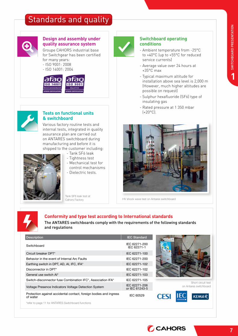
HV shock wave test on Antares switchboard
Short circuit test on Antares switchboard
Tank SF6 leak test at Cahors Factory
Description IEC Standard
Switchboard IEC 62271-200 IEC 62271-1
Circuit breaker DPT* IEC 62271-100Behavior in the event of Internal Arc Faults IEC 62271-200Earthing switch in DPT, AD, AI, IFC, IFA* IEC 62271-102Disconnector in DPT* IEC 62271-102General use switch AI* IEC 62271-103Switch-disconnector fuse Combination IFC*, Association IFA* IEC 62271-105
Voltage Presence Indicators Voltage Detection System IEC 62271-206 or IEC 61243-5
Protection against accidental contact, foreign bodies and ingress of water IEC 60529
*refer to page 11 for ANTARES Switchboard functions
Conformity and type test according to International standards the antareS switchboards comply with the requirements of the following standards and regulations
Switchboard operating conditions- ambient temperature from -25°c
to +40°c (up to +55°c for reduced service currents)
- average value over 24 hours at +35°c max
- typical maximum altitude for installation above sea level is 2,000 m (however, much higher altitudes are possible on request)
- sulphur hexafluoride (sF6) type of insulating gas
- rated pressure at 1 350 mbar (+20°c).
Design and assembly under quality assurance systemGroupe cahors industrial base for switchgear has been certified for many years:- iso 9001: 2008- iso 14001: 2004
Tests on functional units & switchboard Various factory routine tests and internal tests, integrated in quality assurance plan are carried out on aNtarEs switchboard during manufacturing and before it is shipped to the customer including:
- tank sF6 leak- tightness test- Mechanical test for
control mechanisms- dielectric tests.
Standards and quality
8
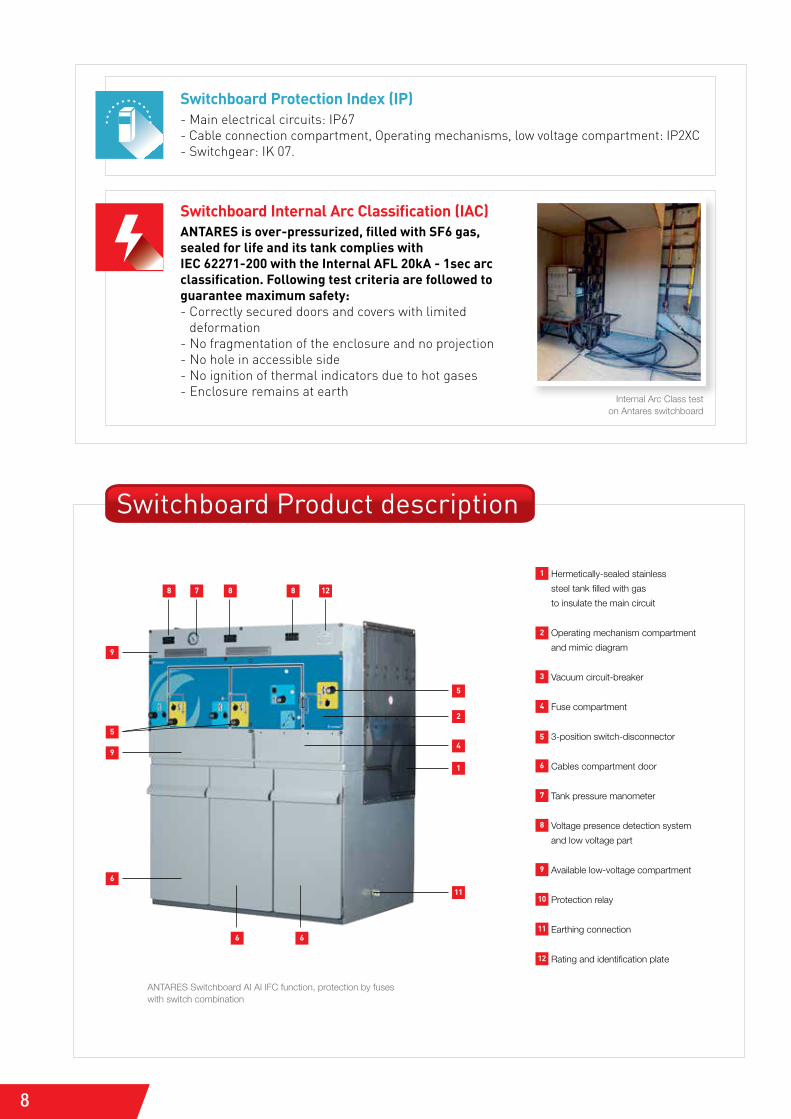
Switchboard Internal Arc Classification (IAC)ANTARES is over-pressurized, filled with SF6 gas, sealed for life and its tank complies with IEC 62271-200 with the Internal AFL 20kA - 1sec arc classification. Following test criteria are followed to guarantee maximum safety:- correctly secured doors and covers with limited
deformation- No fragmentation of the enclosure and no projection- No hole in accessible side- No ignition of thermal indicators due to hot gases- Enclosure remains at earth
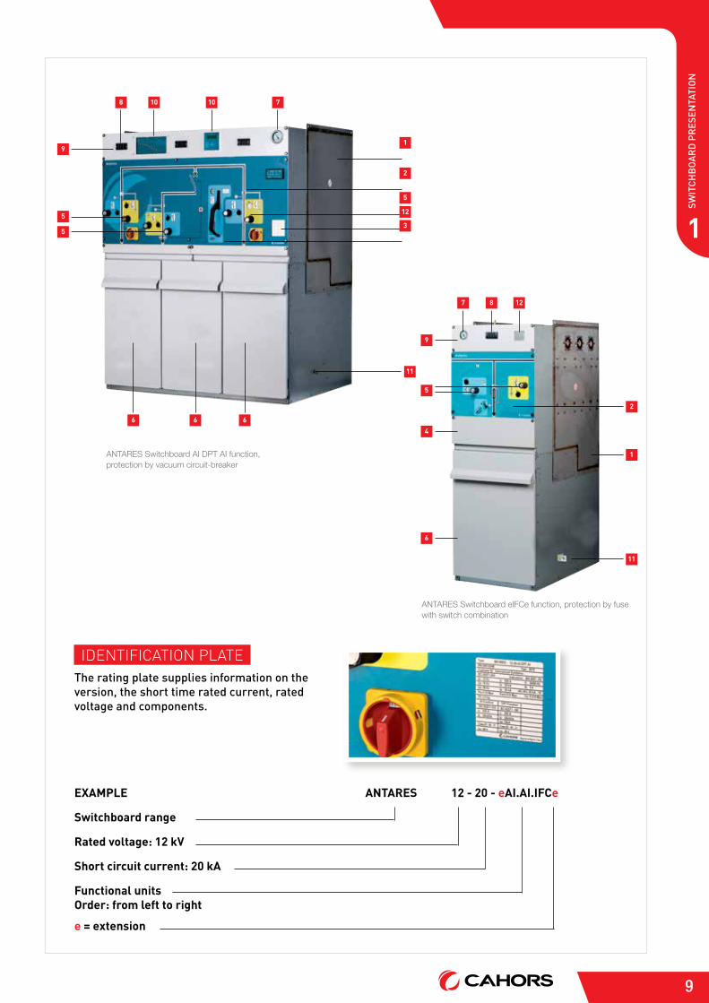
Switchboard Product description
1 Hermetically-sealed stainless
steel tank filled with gas
to insulate the main circuit
2 Operating mechanism compartment
and mimic diagram
3 Vacuum circuit-breaker
4 Fuse compartment
5 3-position switch-disconnector
6 Cables compartment door
7 Tank pressure manometer
8 Voltage presence detection system
and low voltage part
9 Available low-voltage compartment
10 Protection relay
11 Earthing connection
12 Rating and identification plate
Internal Arc Class test on Antares switchboard
Switchboard Protection Index (IP)- Main electrical circuits: iP67- cable connection compartment, operating mechanisms, low voltage compartment: iP2Xc - switchgear: iK 07.
ANTARES Switchboard AI AI IFC function, protection by fuses with switch combination
8
6 6
8 8 127
5
2
1
4
11
6
9
9
5
9
1
Swit
ch
bo
ar
d P
reS
enta
tio
n
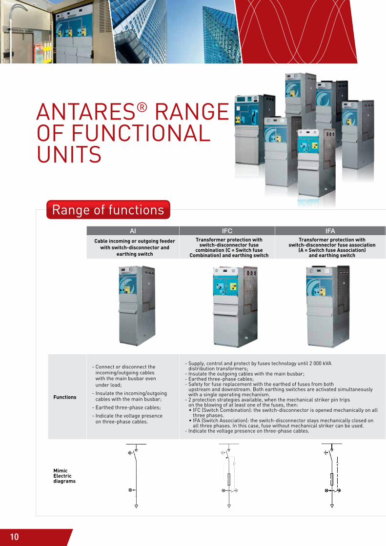
ANTARES Switchboard eIFCe function, protection by fuse with switch combination
ANTARES Switchboard AI DPT AI function, protection by vacuum circuit-breaker
1
710
7 8 12
108
5
5
4
9
5
6
9
6 6 6
2
12
5
11
2
1
11
3
idENtiFicatioN PlatEthe rating plate supplies information on the version, the short time rated current, rated voltage and components.
ExAMPLE
Switchboard range
Rated voltage: 12 kV
Short circuit current: 20 kA
Functional unitsOrder: from left to right
e = extension
ANTARES 12 - 20 - eAI.AI.IFCe
10
AnTARES® RAnGE Of funCTIOnAL unITS
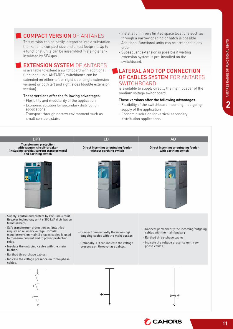
AI IFC IFA DPT LD AD
Cable incoming or outgoing feeder with switch-disconnector and
earthing switch
Transformer protection with switch-disconnector fuse
combination (C = Switch fuse Combination) and earthing switch
Transformer protection with switch-disconnector fuse association
(A = Switch fuse Association) and earthing switch
Transformer protection with vacuum circuit-breaker
(including toroidal current transformers) and earthing switch
Direct incoming or outgoing feeder without earthing switch
Direct incoming or outgoing feeder with earthing switch
Functions
- Connect or disconnect the incoming/outgoing cables with the main busbar even under load;
- Insulate the incoming/outgoing cables with the main busbar;
- Earthed three-phase cables;
- Indicate the voltage presence on three-phase cables.
- Supply, control and protect by fuses technology until 2 000 kVA distribution transformers;
- Insulate the outgoing cables with the main busbar;- Earthed three-phase cables;- Safety for fuse replacement with the earthed of fuses from both
upstream and downstream. both earthing switches are activated simultaneously with a single operating mechanism.
- 2 protection strategies available, when the mechanical striker pin trips on the blowing of at least one of the fuses, then:
• IfC (Switch Combination): the switch-disconnector is opened mechanically on all three phases.
• IfA (Switch Association): the switch-disconnector stays mechanically closed on all three phases. In this case, fuse without mechanical striker can be used.
- Indicate the voltage presence on three-phase cables.
- Supply, control and protect by Vacuum Circuit breaker technology until 6 300 kVA distribution transformers;
- Safe transformer protection as fault trips require no auxiliary voltage. Toroidal transformers on main 3 phases cables is used to measure current and to power protection relay.
- Insulate the outgoing cables with the main busbar;
- Earthed three-phase cables;- Indicate the voltage presence on three-phase
cables.
- Connect permanently the incoming/outgoing cables with the main busbar;
- Optionally, Ld can indicate the voltage presence on three-phase cables.
- Connect permanently the incoming/outgoing cables with the main busbar;
- Earthed three-phase cables;
- Indicate the voltage presence on three-phase cables.
Mimic Electric diagrams
Range of functions
11
AN
TAR
ES R
AN
GE
OF
FUN
CTI
ON
AL
UN
ITS
2
AI IFC IFA DPT LD AD
Cable incoming or outgoing feeder with switch-disconnector and
earthing switch
Transformer protection with switch-disconnector fuse
combination (C = Switch fuse Combination) and earthing switch
Transformer protection with switch-disconnector fuse association
(A = Switch fuse Association) and earthing switch
Transformer protection with vacuum circuit-breaker
(including toroidal current transformers) and earthing switch
Direct incoming or outgoing feeder without earthing switch
Direct incoming or outgoing feeder with earthing switch
Functions
- Connect or disconnect the incoming/outgoing cables with the main busbar even under load;
- Insulate the incoming/outgoing cables with the main busbar;
- Earthed three-phase cables;
- Indicate the voltage presence on three-phase cables.
- Supply, control and protect by fuses technology until 2 000 kVA distribution transformers;
- Insulate the outgoing cables with the main busbar;- Earthed three-phase cables;- Safety for fuse replacement with the earthed of fuses from both
upstream and downstream. both earthing switches are activated simultaneously with a single operating mechanism.
- 2 protection strategies available, when the mechanical striker pin trips on the blowing of at least one of the fuses, then:
• IfC (Switch Combination): the switch-disconnector is opened mechanically on all three phases.
• IfA (Switch Association): the switch-disconnector stays mechanically closed on all three phases. In this case, fuse without mechanical striker can be used.
- Indicate the voltage presence on three-phase cables.
- Supply, control and protect by Vacuum Circuit breaker technology until 6 300 kVA distribution transformers;
- Safe transformer protection as fault trips require no auxiliary voltage. Toroidal transformers on main 3 phases cables is used to measure current and to power protection relay.
- Insulate the outgoing cables with the main busbar;
- Earthed three-phase cables;- Indicate the voltage presence on three-phase
cables.
- Connect permanently the incoming/outgoing cables with the main busbar;
- Optionally, Ld can indicate the voltage presence on three-phase cables.
- Connect permanently the incoming/outgoing cables with the main busbar;
- Earthed three-phase cables;
- Indicate the voltage presence on three-phase cables.
Mimic Electric diagrams
comPact verSion oF aNtarEs this version can be easily integrated into a substation thanks to its compact size and small footprint. Up to 4 functional units can be assembled in a single tank insulated by sF6 gas.
extenSion SyStem oF aNtarEs is available to extend a switchboard with additional functional unit. aNtarEs switchboard can be extended on either left or right side (single extension version) or both left and right sides (double extension version).
these versions offer the following advantages:- Flexibility and modularity of the application- Economic solution for secondary distribution
applications- transport through narrow environment such as
small corridor, stairs
- installation in very limited space locations such as through a narrow opening or hatch is possible
- additional functional units can be arranged in any order
- subsequent extension is possible if waiting extension system is pre-installed on the switchboard.
lateral and toP connection of cableS SyStem For aNtarEs switchboard is available to supply directly the main busbar of the medium voltage switchboard.
these versions offer the following advantages:- Flexibility of the switchboard incoming – outgoing
supply of the application- Economic solution for vertical secondary
distribution applications
12
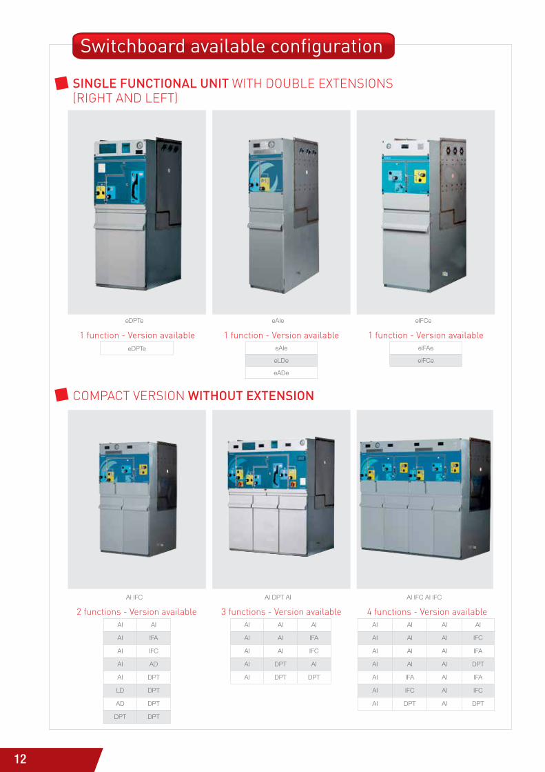
SinGle functional unit with doUblE EXtENsioNs(riGht aNd lEFt)
coMPact VErsioN without extenSion
AI IFC AI DPT AI AI IFC AI IFC
eDPTe eAIe eIFCe
Switchboard available configuration
AI AI
AI IFA
AI IFC
AI AD
AI DPT
LD DPT
AD DPT
DPT DPT
2 functions - Version availableAI AI AI
AI AI IFA
AI AI IFC
AI DPT AI
AI DPT DPT
3 functions - Version availableAI AI AI AI
AI AI AI IFC
AI AI AI IFA
AI AI AI DPT
AI IFA AI IFA
AI IFC AI IFC
AI DPT AI DPT
4 functions - Version available
eDPTe
1 function - Version availableeAIe
eLDe
eADe
1 function - Version availableeIFAe
eIFCe
1 function - Version available
13
AN
TAR
ES R
AN
GE
OF
FUN
CTI
ON
AL
UN
ITS
2
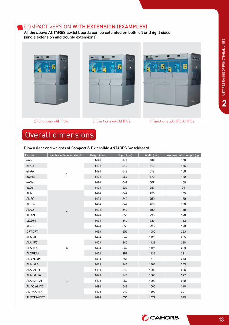
dimensions and weights of compact & extensible antareS Switchboard
coMPact VErsioN with extenSion (examPleS)All the above ANTARES switchboards can be extended on both left and right sides (single extension and double extensions)
Function Number of functional units Height (mm) Depth (mm) Width (mm) Approximative weight (kg)
eAIe
1
1424 842 387 106
eIFCe 1424 842 512 145
eIFAe 1424 842 512 136
eDPTe 1424 856 572 149
eADe 1424 842 387 106
eLDe 1424 837 387 90
AI AI
2
1424 842 750 155
AI.IFC 1424 842 750 189
AI. IFA 1424 842 750 180
AI.AD 1424 842 750 155
AI.DPT 1424 856 935 198
LD.DPT 1424 842 935 182
AD-DPT 1424 856 935 198
DPT.DPT 1424 856 1050 233
AI.AI.AI
3
1424 842 1125 205
AI.AI.IFC 1424 842 1125 238
AI.AI.IFA 1424 842 1125 229
AI.DPT.AI 1424 856 1125 231
AI.DPT.DPT 1424 856 1310 273
AI.AI.AI.AI
4
1424 842 1500 253
AI.AI.AI.IFC 1424 842 1500 286
AI.AI.AI.IFA 1424 842 1500 277
AI.AI.DPT.AI 1424 856 1500 279
AI.IFC.AI.IFC 1424 842 1500 319
AI.IFA.AI.IFA 1424 842 1500 301
AI.DPT.AI.DPT 1424 856 1572 313
2 functions eai iFce 3 functions eai ai iFce 4 functions eai iFc ai iFce
Overall dimensions
14
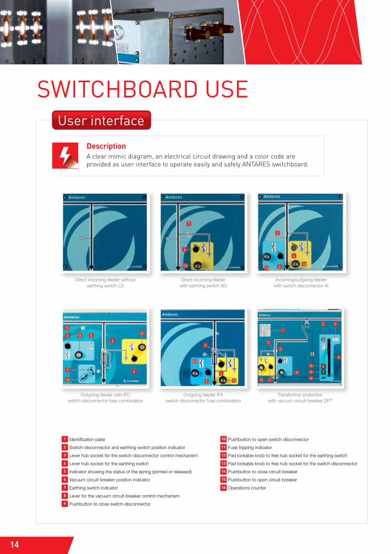
user interface
SwITCHbOARd uSE
Direct incoming feeder without earthing switch LD
Incoming/outgoing feeder with switch-disconnector AI
Outgoing feeder IFA switch-disconnector fuse combination
Direct incoming feeder with earthing switch AD
Outgoing feeder with IFC switch-disconnector fuse combination
Transformer protection with vacuum circuit-breaker DPT
1 Identification plate
2 Switch-disconnector and earthing switch position indicator
3 Lever hub socket for the switch-disconnector control mechanism
4 Lever hub socket for the earthing switch
5 Indicator showing the status of the spring (primed or released)
6 Vacuum circuit-breaker position indicator
7 Earthing switch indicator
8 Lever for the vacuum circuit-breaker control mechanism
9 Pushbutton to close switch-disconnector
10 Pushbutton to open switch-disconnector
11 Fuse tripping indicator
12 Pad lockable knob to free hub socket for the earthing switch
13 Pad lockable knob to free hub socket for the switch-disconnector
14 Pushbutton to close circuit-breaker
15 Pushbutton to open circuit-breaker
16 Operations counter
Descriptiona clear mimic diagram, an electrical circuit drawing and a color code are provided as user interface to operate easily and safely aNtarEs switchboard.
15
3
Swit
ch
bo
ar
d u
Se
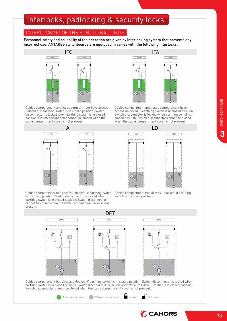
Interlocks, padlocking & security locksiNtErlocKiNG oF thE FUNctioNal UNits
Personnel safety and reliability of the operation are given by interlocking system that prevents any incorrect use. antareS switchboards are equipped in series with the following interlocks.
IfC IfA
cables compartment and fuses compartment have access unlocked, if earthing switch is in closed position. switch disconnector is locked when earthing switch is in closed position. switch disconnector cannot be closed when the cable compartment cover is not present.
cables compartment and fuses compartment have access unlocked, if earthing switch is in closed position. switch disconnector is locked when earthing switch is in closed position. switch disconnector cannot be closed when the cable compartment cover is not present.
AI LD
cables compartment has access unlocked, if earthing switch is in closed position. switch disconnector is locked when earthing switch is in closed position. switch disconnector cannot be closed when the cable compartment cover is not present.
cables compartment has access unlocked, if earthing switch is in closed position.
DPT
cables compartment has access unlocked, if earthing switch is in closed position. switch disconnector is locked when earthing switch is in closed position. switch disconnector is locked when Vacuum circuit breaker is in closed position. switch disconnector cannot be closed when the cable compartment cover is not present.
Fuse compartment Locked UnlockedCables compartment
16
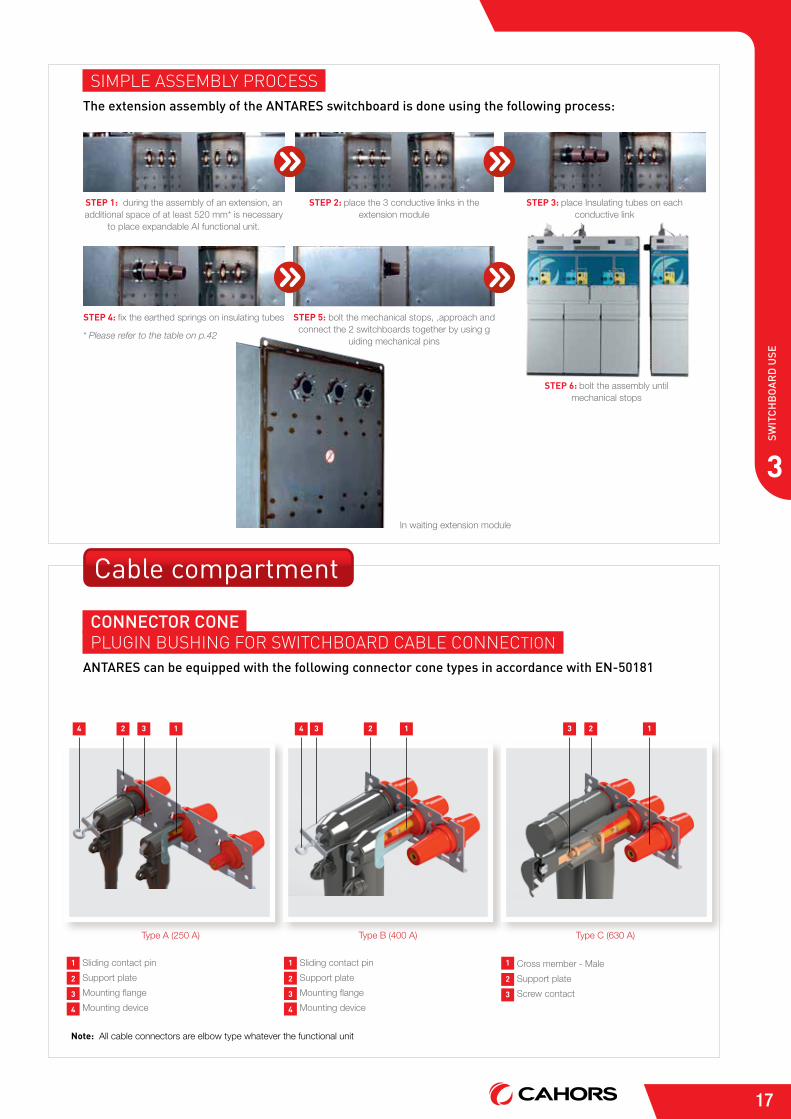
ExtensibilityEXtENsibility oF aNtarEs For bUsbar MaXiMUM cUrrENt UNtil 630 a
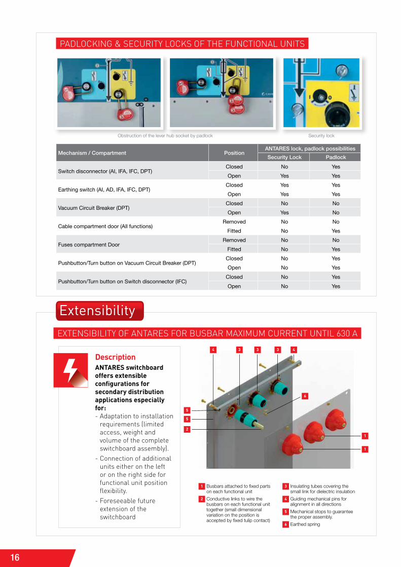
PadlocKiNG & sEcUrity locKs oF thE FUNctioNal UNits
Obstruction of the lever hub socket by padlock Security lock
Mechanism / Compartment PositionANTARES lock, padlock possibilities
Security Lock Padlock
Switch disconnector (AI, IFA, IFC, DPT)Closed No YesOpen Yes Yes
Earthing switch (AI, AD, IFA, IFC, DPT)Closed Yes YesOpen Yes Yes
Vacuum Circuit Breaker (DPT)Closed No NoOpen Yes No
Cable compartment door (All functions)Removed No No
Fitted No Yes
Fuses compartment DoorRemoved No No
Fitted No Yes
Pushbutton/Turn button on Vacuum Circuit Breaker (DPT)Closed No YesOpen No Yes
Pushbutton/Turn button on Switch disconnector (IFC)Closed No YesOpen No Yes
DescriptionANTARES switchboard offers extensible configurations for secondary distribution applications especially for:- adaptation to installation
requirements (limited access, weight and volume of the complete switchboard assembly).
- connection of additional units either on the left or on the right side for functional unit position flexibility.
- Foreseeable future extension of the switchboard
1 Busbars attached to fixed parts on each functional unit
2 Conductive links to wire the busbars on each functional unit together (small dimensional variation on the position is accepted by fixed tulip contact)
3 Insulating tubes covering the small link for dielectric insulation
4 Guiding mechanical pins for alignment in all directions
5 Mechanical stops to guarantee the proper assembly.
6 Earthed spring
5
5
4 4
6
3 3 3
2
1
1
17
3
Swit
ch
bo
ar
d u
Se
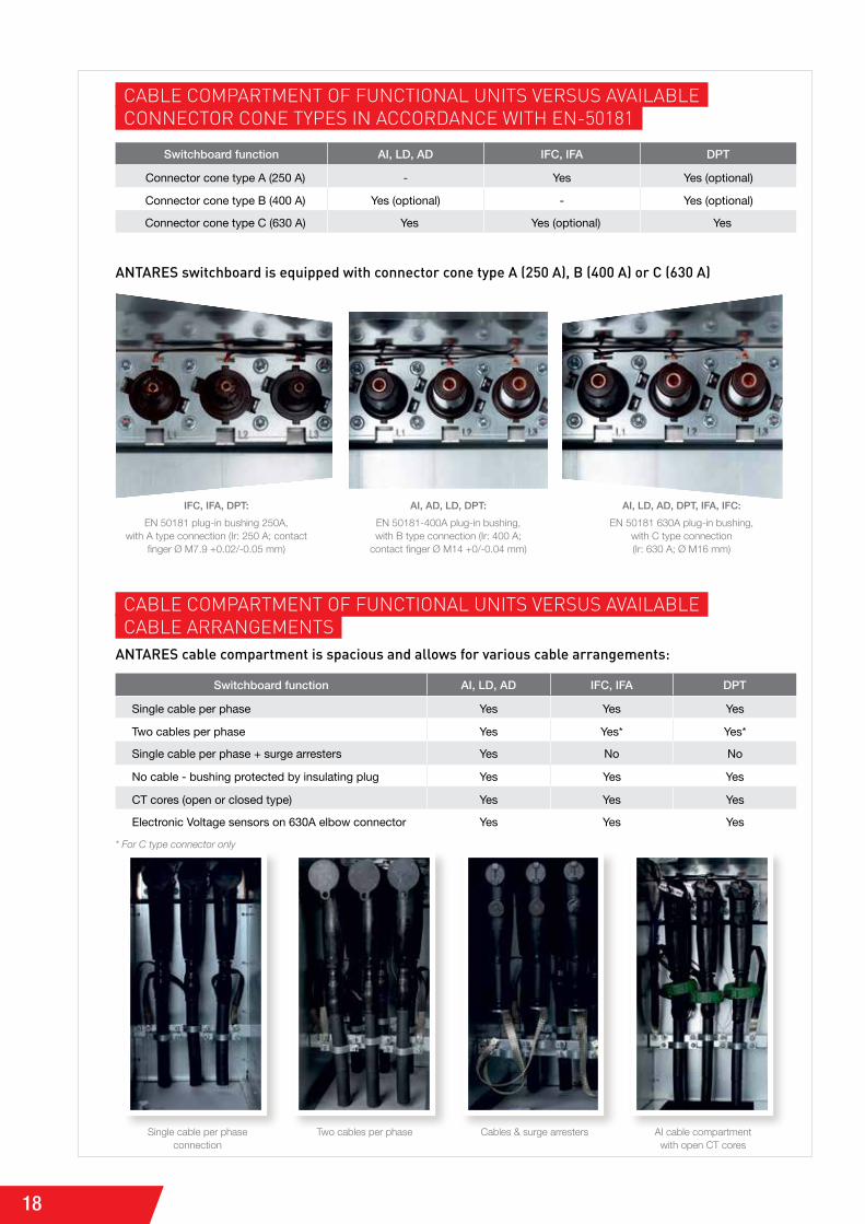
siMPlE assEMbly ProcEssthe extension assembly of the antareS switchboard is done using the following process:
In waiting extension module
* Please refer to the table on p.42
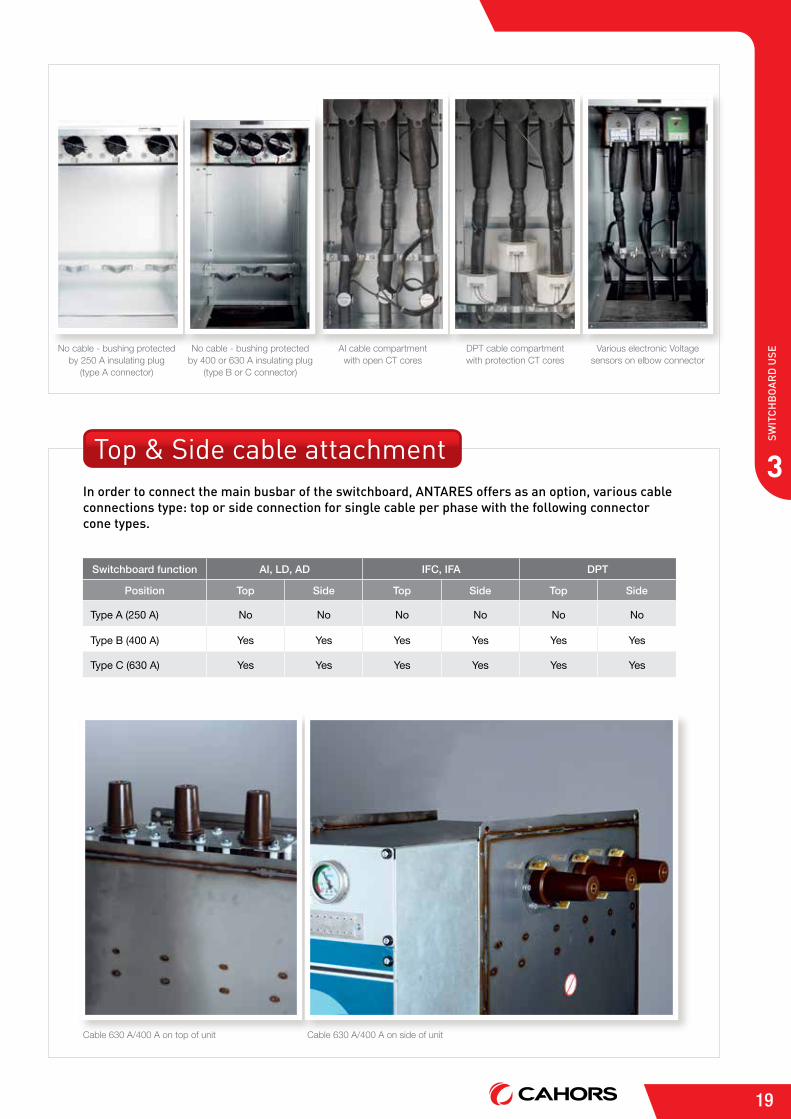
Type A (250 A) Type B (400 A) Type C (630 A)
STEP 1: during the assembly of an extension, an additional space of at least 520 mm* is necessary
to place expandable AI functional unit.
STEP 3: place Insulating tubes on each conductive link
STEP 5: bolt the mechanical stops, ,approach and connect the 2 switchboards together by using g
uiding mechanical pins
STEP 2: place the 3 conductive links in the extension module
STEP 4: fix the earthed springs on insulating tubes
STEP 6: bolt the assembly until mechanical stops
Cable compartment
connector cone PlUGiN bUshiNG For switchboard cablE coNNEctioN
antareS can be equipped with the following connector cone types in accordance with en-50181
Note: All cable connectors are elbow type whatever the functional unit
1 Sliding contact pin
2 Support plate
3 Mounting flange
4 Mounting device
1 Sliding contact pin
2 Support plate
3 Mounting flange
4 Mounting device
1 Cross member - Male
2 Support plate
3 Screw contact
2 2 23 3 34 41 1 1
18
Switchboard function AI, LD, AD IFC, IFA DPT
Single cable per phase Yes Yes Yes
Two cables per phase Yes Yes* Yes*
Single cable per phase + surge arresters Yes No No
No cable - bushing protected by insulating plug Yes Yes Yes
CT cores (open or closed type) Yes Yes Yes
Electronic Voltage sensors on 630A elbow connector Yes Yes Yes
cablE coMPartMENt oF FUNctioNal UNits VErsUs aVailablEcablE arraNGEMENts
antareS cable compartment is spacious and allows for various cable arrangements:
Single cable per phase connection
Two cables per phase Cables & surge arresters AI cable compartment with open CT cores
antareS switchboard is equipped with connector cone type a (250 a), b (400 a) or c (630 a)
Switchboard function AI, LD, AD IFC, IFA DPT
Connector cone type A (250 A) - Yes Yes (optional)
Connector cone type B (400 A) Yes (optional) - Yes (optional)
Connector cone type C (630 A) Yes Yes (optional) Yes
cablE coMPartMENt oF FUNctioNal UNits VErsUs aVailablE coNNEctor coNE tyPEs iN accordaNcE with EN-50181
IFC, IFA, DPT:
EN 50181 plug-in bushing 250A, with A type connection (Ir: 250 A; contact
finger Ø M7.9 +0.02/-0.05 mm)
AI, LD, AD, DPT, IFA, IFC:
EN 50181 630A plug-in bushing, with C type connection (Ir: 630 A; Ø M16 mm)
AI, AD, LD, DPT:
EN 50181-400A plug-in bushing, with B type connection (Ir: 400 A;
contact finger Ø M14 +0/-0.04 mm)
* For C type connector only
19
3
Swit
ch
bo
ar
d u
Se
Switchboard function AI, LD, AD IFC, IFA DPT
Position Top Side Top Side Top Side
Type A (250 A) No No No No No No
Type B (400 A) Yes Yes Yes Yes Yes Yes
Type C (630 A) Yes Yes Yes Yes Yes Yes
Cable 630 A/400 A on top of unit Cable 630 A/400 A on side of unit
Top & Side cable attachmentin order to connect the main busbar of the switchboard, antareS offers as an option, various cable connections type: top or side connection for single cable per phase with the following connector cone types.
No cable - bushing protected by 250 A insulating plug
(type A connector)
AI cable compartment with open CT cores
DPT cable compartment with protection CT cores
Various electronic Voltage sensors on elbow connector
No cable - bushing protected by 400 or 630 A insulating plug
(type B or C connector)
20
underground cables are required to be checked after installation, before being put into service and periodically during service life of an installation. depending on the cable elbow connectors used in medium voltage switchgear, different options are available within antareS switchboard to test the cables dielectric characteristics by voltage injection.
VoltaGE iNjEctioN PlUGiN systEMFirst case is when, there is no specific access point acting as a cable testing facility to connect the voltage source. in this case, the cable elbow connectors have no access point (e.g. plugged elbow connector), so the only way to test the cables is to disconnect them one by one. in this case, antares switchboard can be provided with a voltage injection plugin system (optional).
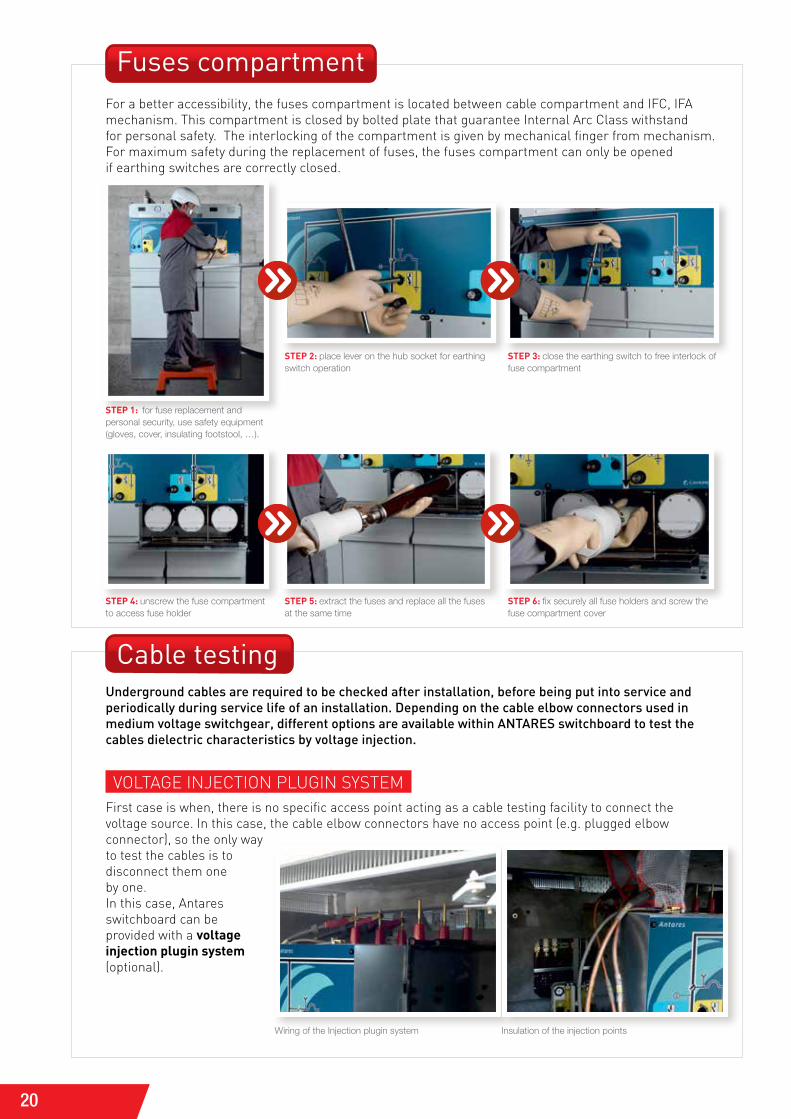
STEP 1: for fuse replacement and personal security, use safety equipment (gloves, cover, insulating footstool, …).
STEP 2: place lever on the hub socket for earthing switch operation
STEP 4: unscrew the fuse compartment to access fuse holder
STEP 3: close the earthing switch to free interlock of fuse compartment
STEP 5: extract the fuses and replace all the fuses at the same time
STEP 6: fix securely all fuse holders and screw the fuse compartment cover
fuses compartmentFor a better accessibility, the fuses compartment is located between cable compartment and iFc, iFa mechanism. this compartment is closed by bolted plate that guarantee internal arc class withstandfor personal safety. the interlocking of the compartment is given by mechanical finger from mechanism.For maximum safety during the replacement of fuses, the fuses compartment can only be opened if earthing switches are correctly closed.
Cable testing
Wiring of the Injection plugin system Insulation of the injection points

21
3
Swit
ch
bo
ar
d u
SeiNsUlatiNG tEst rod toolsecond case is when, there is no specific point acting as a cable testing facility to connect the voltage source but the cable connectors have access point (e.g. bolted elbow connector). in this case, we have the possibility to connect the voltage source in a specific point by removing the back-plug of the connector and placing an insulating test rod tool through it.
optionally, antares switchboard can be equipped on ai unit (cable incoming or outgoing feeder with switch disconnector) with specific injection points acting as always accessible cable testing facility to connect the voltage source.in service, the specific points for voltage injection are shorted by an accessible external earthing bar. so, to inject the test voltage, it is necessary to open the earthing circuit of the switchgear, by removal of the short-circuiting bar as explained in the figures.
when bolted elbow connector is used, antares switchboard can be delivered with insulated test rod tool. the test voltage is supplied as explained in the figures.
Voltage is applied to check HV cable dielectric properties
STEP 1: open the cable compartment
STEP 3: place the rod tool on the adaptor STEP 4: start the injection test
STEP 2: remove the back-plug of the elbow connector and place the tool adaptors
22
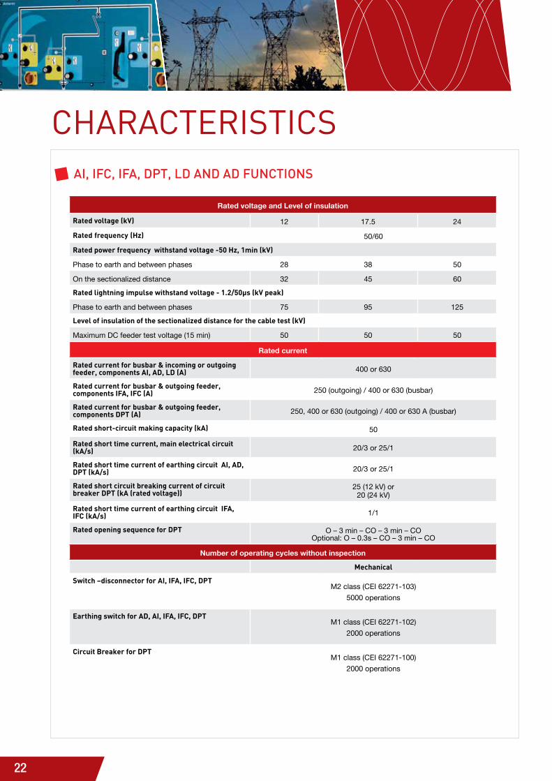
CHARACTERISTICSai, ifc, ifa, dPt, ld and ad functionS
Rated voltage and Level of insulation
Rated voltage (kV) 12 17.5 24
Rated frequency (Hz) 50/60
Rated power frequency withstand voltage -50 Hz, 1min (kV)
Phase to earth and between phases 28 38 50
On the sectionalized distance 32 45 60
Rated lightning impulse withstand voltage - 1.2/50µs (kV peak)
Phase to earth and between phases 75 95 125
Level of insulation of the sectionalized distance for the cable test (kV)
Maximum DC feeder test voltage (15 min) 50 50 50
Rated current
Rated current for busbar & incoming or outgoing feeder, components AI, AD, LD (A) 400 or 630
Rated current for busbar & outgoing feeder, components IFA, IFC (A) 250 (outgoing) / 400 or 630 (busbar)
Rated current for busbar & outgoing feeder, components DPT (A) 250, 400 or 630 (outgoing) / 400 or 630 A (busbar)
Rated short-circuit making capacity (kA) 50
Rated short time current, main electrical circuit (kA/s) 20/3 or 25/1
Rated short time current of earthing circuit AI, AD, DPT (kA/s) 20/3 or 25/1
Rated short circuit breaking current of circuit breaker DPT (kA (rated voltage))
25 (12 kV) or 20 (24 kV)
Rated short time current of earthing circuit IFA, IFC (kA/s) 1/1
Rated opening sequence for DPT O – 3 min – CO – 3 min – CO Optional: O – 0.3s – CO – 3 min – CO
Number of operating cycles without inspection
Mechanical
Switch –disconnector for AI, IFA, IFC, DPTM2 class (CEI 62271-103)
5000 operations
Earthing switch for AD, AI, IFA, IFC, DPTM1 class (CEI 62271-102)
2000 operations
Circuit Breaker for DPTM1 class (CEI 62271-100)
2000 operations

23
Ch
ar
aC
ter
isti
Cs
4
choice oF MEchaNisMs aNd EqUiPMENt 3 types of mechanism operating principles
Type A
Type A mechanism is a tumbler mechanism with a dead point passage. The energy is stored and free during the handle movement.- Manual: the opening or closing operation is independent of the operator force and speed. The operation is then performed without any duration or time constraint.
- Motorized: the opening or closing operations are performed by a motor. Manual opening and closing is still possible.
Type B
Type B mechanism is a spring mechanism with 2 latch-in features for opening and closing. The energy needed for opening and closing is stored during the load of a spring.The operator manually loads spring in one single operation for next closing and future opening. Closing can be completed by using turn-button. The fuse switch-disconnector mechanism is thus ready for a snap opening operation. Tripping can be performed with a coil, a fuse striker or a turn-button.
Type C
These operating mechanisms use the energy stored by springs to close and open the circuit-breaker on the DPT function. - Manual: the operator manually operates to load the control mechanism’s spring. The spring is held in place by a
latch, freed manually by a mechanical button, causing: - the release of the spring - the closing of the Cb - the arming of the trip spring, now held in place by a latch.It is thus possible to open the circuit-breaker by freeing the trip spring latch manually (mechanical button) or electrically (electro-magnet).note: with the circuit-breaker closed, it is possible optionally to rearm the closing spring, which authorises a rapid re-closure cycle.- Motorized: the closing spring is armed by a motor (arming time < 15 s). Opening and closure operations are carried out electrically (magnets).note: It is possible to arm, close and trip the circuit-breakers manually.
Functions
Type of operating mechanism AI IFC IFA DPT LD AD
Switch - disconnector Type A
Fuse switch - disconnector (only manual)
Type B
Earthing switch (manually drive only) Type A
Circuit-breaker Type C
Possible options on mechanism AI IFC IFA DPT LD AD
Manual opening and closing as a standard
Mechanical position indicator as a standard
Motorization as an option
Trip coil (option)
(standard)
2nd trip coil (option)
Autonomous tripping device without any auxiliary source (striker)
Operating counter (option)
(option)
(option)
(standard)
(option)
Optional auxiliary contact AI IFC IFA DPT LD AD
Switch –disconnector position
Earthing switch position
Fuse blown indicators
Vacuum circuit-breaker position
Note: electrical characteristics available on request for trip coil, motorization, auxiliary contacts

24
fuses & Selection of Medium Voltage fuses
ACCESSORIESAnd OPTIOnS
Operating rated Voltage (kV)
Power rating of transformer (kVA)
50 75 100 125 160 200 250 315 400 500 630 800 1000 1250 1600 2000
12 10 10 16 20 25 25 31,5 40 50 50 63 80 100
17.5 10 10 10 10 16 20 25 31,5 31,5 40 50 50 63 80 100
24 10 10 10 10 16 16 20 25 25 31,5 40 40 63 63 80 100
Rated fuses selection tablerating in a, no overload, – 25°c < t°c < 40°c
Types of Medium Voltage fusesthe fuses are used for iFc or iFa functional units to protect distribution transformers. Fuses that have an integrated thermal striker are used for iFc to switch off the switch-disconnector in case of short circuit or to prevent a thermal overload in the fuse holder.
Voltage Length (mm)
Up to 12 kV292
(with mechanical adaptation to extend to 442 mm)
17.5 kV 442
24 kV 442
MV fuse according to IEC 60282-1 standard
Technical characteristicsthe fuses meet the iEc 60282-1 standards and in case of striker, “Medium” type with a maximum initial tripping force of 80 N.
25
5
Ac
ces
sor
ies
An
d o
pti
on
s
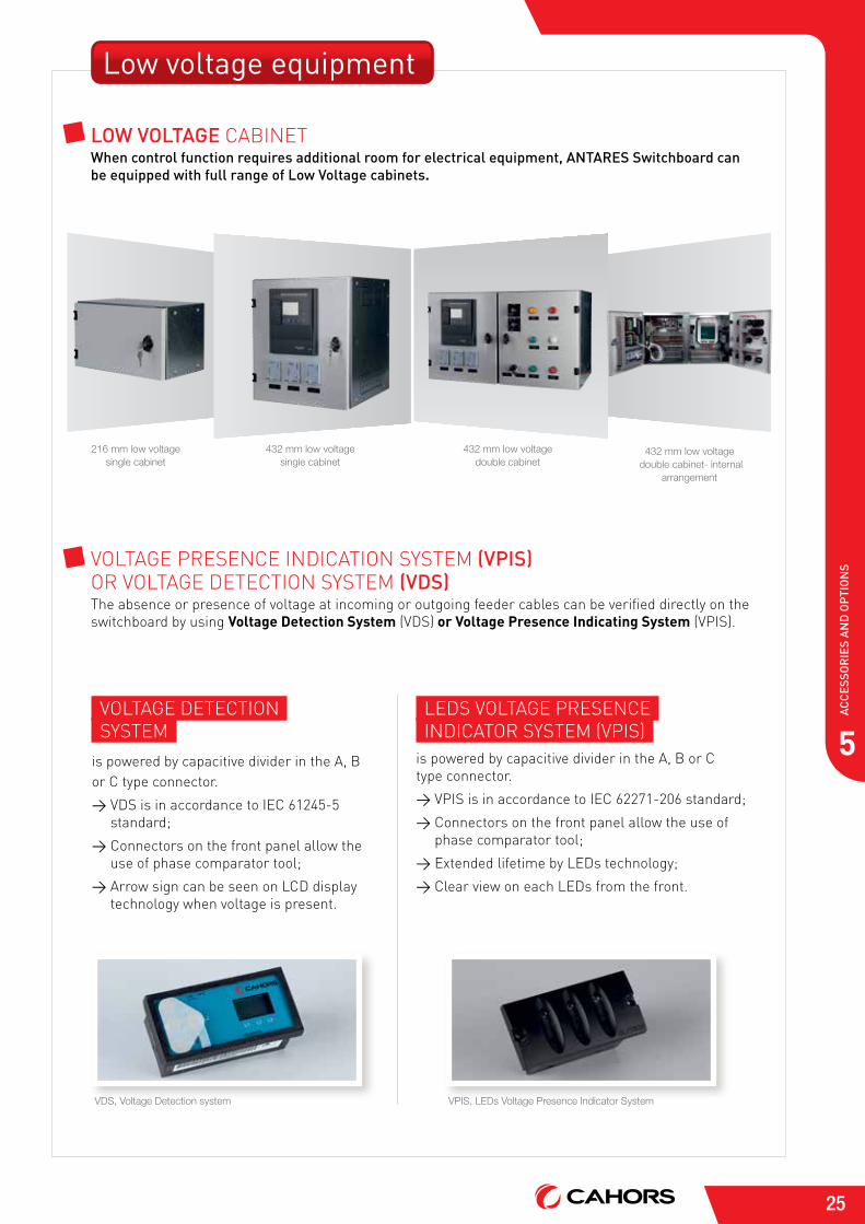
Low voltage equipment
low voltaGe cabiNEtwhen control function requires additional room for electrical equipment, antareS Switchboard can be equipped with full range of low voltage cabinets.
VoltaGE dEtEctioNsystEM
is powered by capacitive divider in the a, b or c type connector.
> Vds is in accordance to iEc 61245-5 standard;
> connectors on the front panel allow the use of phase comparator tool;
> arrow sign can be seen on lcd display technology when voltage is present.
lEds VoltaGE PrEsENcEiNdicator systEM (VPis)
is powered by capacitive divider in the a, b or c type connector.
> VPis is in accordance to iEc 62271-206 standard;
> connectors on the front panel allow the use of phase comparator tool;
> Extended lifetime by lEds technology;
> clear view on each lEds from the front.
VDS, Voltage Detection system VPIS, LEDs Voltage Presence Indicator System
216 mm low voltage single cabinet
432 mm low voltage double cabinet
432 mm low voltage single cabinet
432 mm low voltage double cabinet- internal
arrangement
VoltaGE PrEsENcE iNdicatioN systEM (vPiS) or VoltaGE dEtEctioN systEM (vdS)the absence or presence of voltage at incoming or outgoing feeder cables can be verified directly on the switchboard by using Voltage Detection System (Vds) or Voltage Presence Indicating System (VPis).
26
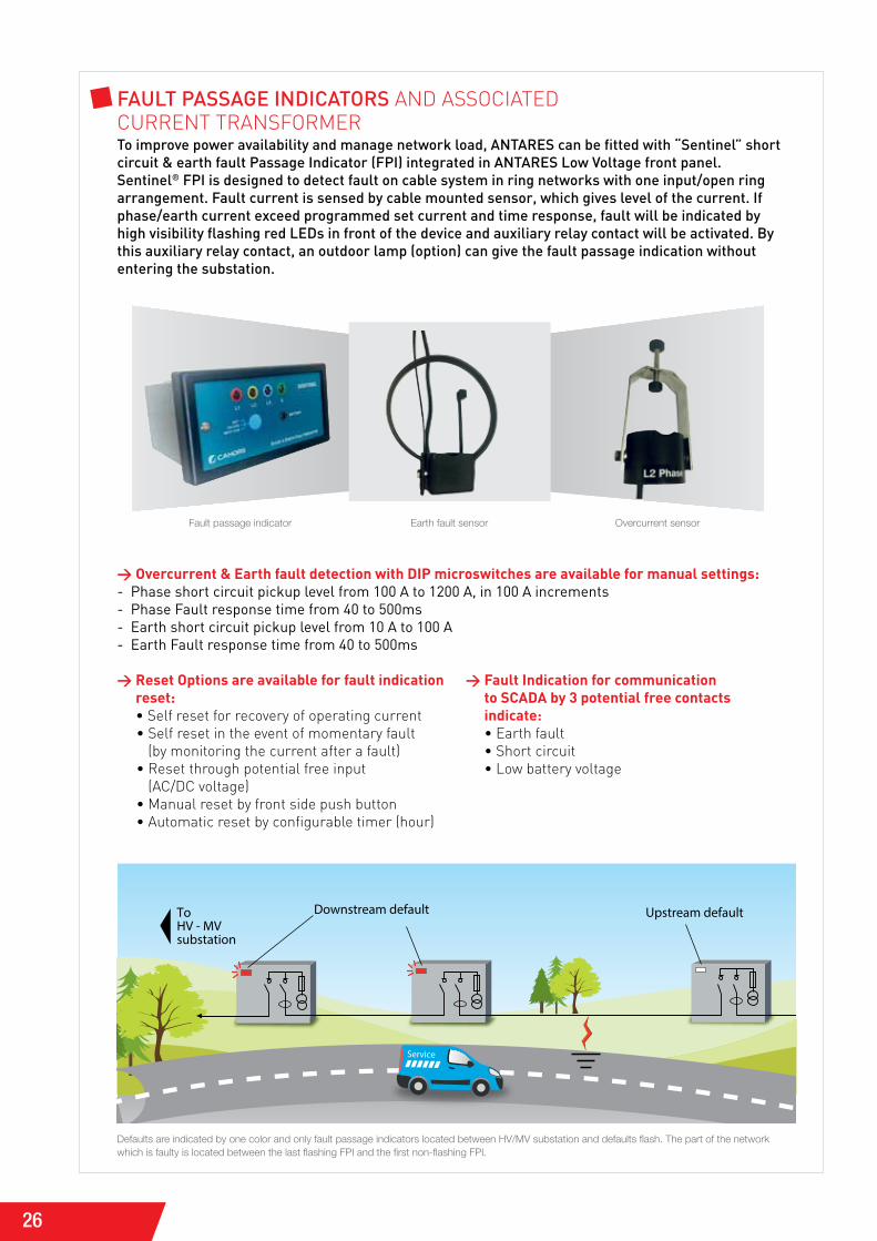
fault PaSSaGe indicatorS aNd associatEd cUrrENt traNsForMErto improve power availability and manage network load, antareS can be fitted with “Sentinel” short circuit & earth fault Passage indicator (fPi) integrated in antareS low voltage front panel.Sentinel® fPi is designed to detect fault on cable system in ring networks with one input/open ring arrangement. fault current is sensed by cable mounted sensor, which gives level of the current. if phase/earth current exceed programmed set current and time response, fault will be indicated by high visibility flashing red leds in front of the device and auxiliary relay contact will be activated. by this auxiliary relay contact, an outdoor lamp (option) can give the fault passage indication without entering the substation.
Service
ToHV - MVsubstation
Downstream default Upstream default
Defaults are indicated by one color and only fault passage indicators located between HV/MV substation and defaults flash. The part of the network which is faulty is located between the last flashing FPI and the first non-flashing FPI.
> Overcurrent & Earth fault detection with DIP microswitches are available for manual settings:- Phase short circuit pickup level from 100 A to 1200 A, in 100 A increments- Phase fault response time from 40 to 500ms- Earth short circuit pickup level from 10 A to 100 A- Earth fault response time from 40 to 500ms
> Reset Options are available for fault indication reset: • self reset for recovery of operating current
• self reset in the event of momentary fault (by monitoring the current after a fault)
• reset through potential free input (ac/dc voltage)
• Manual reset by front side push button • automatic reset by configurable timer (hour)
> Fault Indication for communication to SCADA by 3 potential free contacts indicate: • Earth fault • short circuit • low battery voltage
Fault passage indicator Earth fault sensor Overcurrent sensor
27
5
Ac
ces
sor
ies
An
d o
pti
on
s
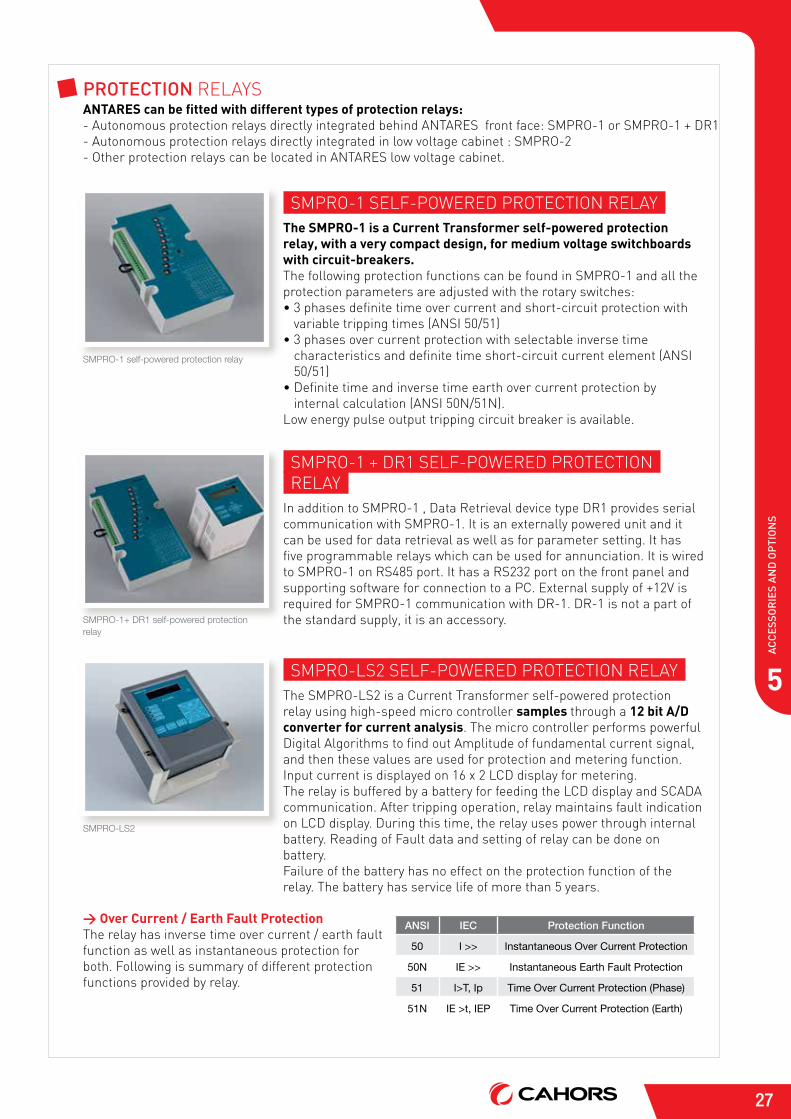
Protection rElaysANTARES can be fitted with different types of protection relays:- autonomous protection relays directly integrated behind aNtarEs front face: sMPro-1 or sMPro-1 + dr1- autonomous protection relays directly integrated in low voltage cabinet : sMPro-2- other protection relays can be located in aNtarEs low voltage cabinet.
sMPro-1 sElF-PowErEd ProtEctioN rElayThe SMPRO-1 is a Current Transformer self-powered protection relay, with a very compact design, for medium voltage switchboards with circuit-breakers.the following protection functions can be found in sMPro-1 and all the protection parameters are adjusted with the rotary switches:• 3 phases definite time over current and short-circuit protection with
variable tripping times (aNsi 50/51)• 3 phases over current protection with selectable inverse time
characteristics and definite time short-circuit current element (aNsi 50/51)
• definite time and inverse time earth over current protection by internal calculation (aNsi 50N/51N).
low energy pulse output tripping circuit breaker is available.
SMPRO-1 self-powered protection relay
sMPro-1 + dr1 sElF-PowErEd ProtEctioN rElay
in addition to sMPro-1 , data retrieval device type dr1 provides serial communication with sMPro-1. it is an externally powered unit and it can be used for data retrieval as well as for parameter setting. it has five programmable relays which can be used for annunciation. it is wired to sMPro-1 on rs485 port. it has a rs232 port on the front panel and supporting software for connection to a Pc. External supply of +12V is required for sMPro-1 communication with dr-1. dr-1 is not a part of the standard supply, it is an accessory.SMPRO-1+ DR1 self-powered protection
relay
sMPro-ls2 sElF-PowErEd ProtEctioN rElaythe sMPro-ls2 is a current transformer self-powered protection relay using high-speed micro controller samples through a 12 bit A/D converter for current analysis. the micro controller performs powerful digital algorithms to find out amplitude of fundamental current signal, and then these values are used for protection and metering function. input current is displayed on 16 x 2 lcd display for metering.the relay is buffered by a battery for feeding the lcd display and scada communication. after tripping operation, relay maintains fault indication on lcd display. during this time, the relay uses power through internal battery. reading of Fault data and setting of relay can be done on battery.Failure of the battery has no effect on the protection function of the relay. the battery has service life of more than 5 years.
SMPRO-LS2
> Over Current / Earth Fault Protectionthe relay has inverse time over current / earth fault function as well as instantaneous protection for both. Following is summary of different protection functions provided by relay.
ANSI IEC Protection Function
50 I >> Instantaneous Over Current Protection
50N IE >> Instantaneous Earth Fault Protection
51 I>T, Ip Time Over Current Protection (Phase)
51N IE >t, IEP Time Over Current Protection (Earth)
28
> Measurement and Communication Functionin normal condition the relay displays all the settings. Using the front keyboard, the display can be programmed to show the actual current flowing through the relay. if current is in fault range, the relay gives trip command. the type of the fault is displayed on lcd display. during the fault condition, the relay measures the fault current and stores it in non-volatile memory. the fault current can be read using keyboard on lcd display. all settings can be done locally and saved in non-volatile memory.
TECHNICAL SPECIFICATIONS
Insulation Voltage 24 kV
Routine testDielectric strength at 50 kVPartial discharges <50pC at 28.8 kVAccuracy 1%
Type testsAC Voltage test, dry and wet at 50 kVLightning impulse voltage test (BIL) at 125 kV
Operating conditions (according to EN 60870-2-2 Class C2) Temperature from -10°C to +60°C Relative humidity from 15 to 100%
Storage conditions (according to EN 60870-2-2 Class C3) Temperature from -25°C to +75°C Relative humidity from 10 to 100%
Voltage divider ratio 10.000/1 VFrequency 50 Hz / 60 Hz
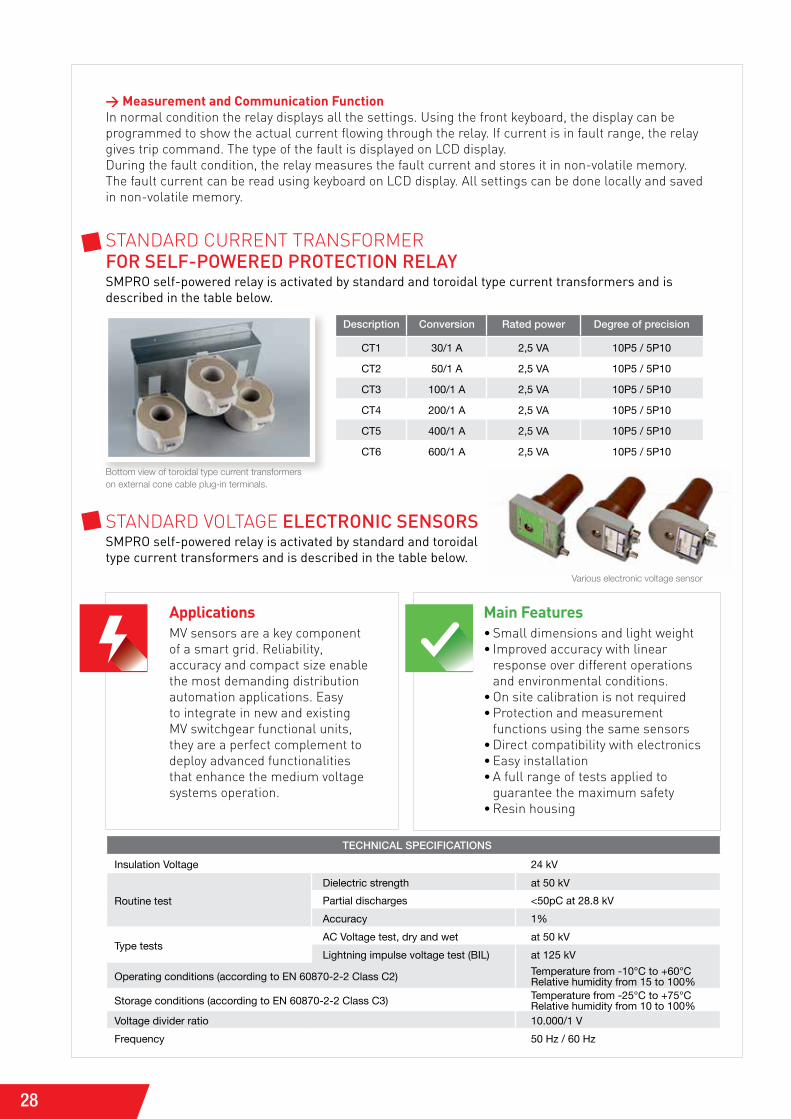
staNdard cUrrENt traNsForMEr for Self-Powered Protection relaySMPRO self-powered relay is activated by standard and toroidal type current transformers and is described in the table below.
Bottom view of toroidal type current transformerson external cone cable plug-in terminals.
Description Conversion Rated power Degree of precision
CT1 30/1 A 2,5 VA 10P5 / 5P10
CT2 50/1 A 2,5 VA 10P5 / 5P10
CT3 100/1 A 2,5 VA 10P5 / 5P10
CT4 200/1 A 2,5 VA 10P5 / 5P10
CT5 400/1 A 2,5 VA 10P5 / 5P10
CT6 600/1 A 2,5 VA 10P5 / 5P10
staNdard VoltaGE electronic SenSorSSMPRO self-powered relay is activated by standard and toroidal type current transformers and is described in the table below.
ApplicationsMV sensors are a key component of a smart grid. reliability, accuracy and compact size enable the most demanding distribution automation applications. Easy to integrate in new and existing MV switchgear functional units, they are a perfect complement to deploy advanced functionalities that enhance the medium voltage systems operation.
Main Features• small dimensions and light weight • improved accuracy with linear
response over different operations and environmental conditions.
• on site calibration is not required• Protection and measurement
functions using the same sensors• direct compatibility with electronics• Easy installation• a full range of tests applied to
guarantee the maximum safety• resin housing
Various electronic voltage sensor
29
5
Ac
ces
sor
ies
An
d o
pti
on
s
I CONTROL-TaN iNtErFacE dEsiGNEd For tElEcoNtrol oF MV NEtworKs
I Control-T is a “plug and play” or multifunction interface that integrates all the functional units necessary for remote supervision and control of ANTARES:> acquisition of the different types of information: switch position, fault detectors, current values...> transmission of switch open/close orders> exchanges with the control center.
required particularly during outages in the network, i control-t is of proven reliability and availability, being able to ensure switchgear operation at any moment. it is simple to set up and to operate.
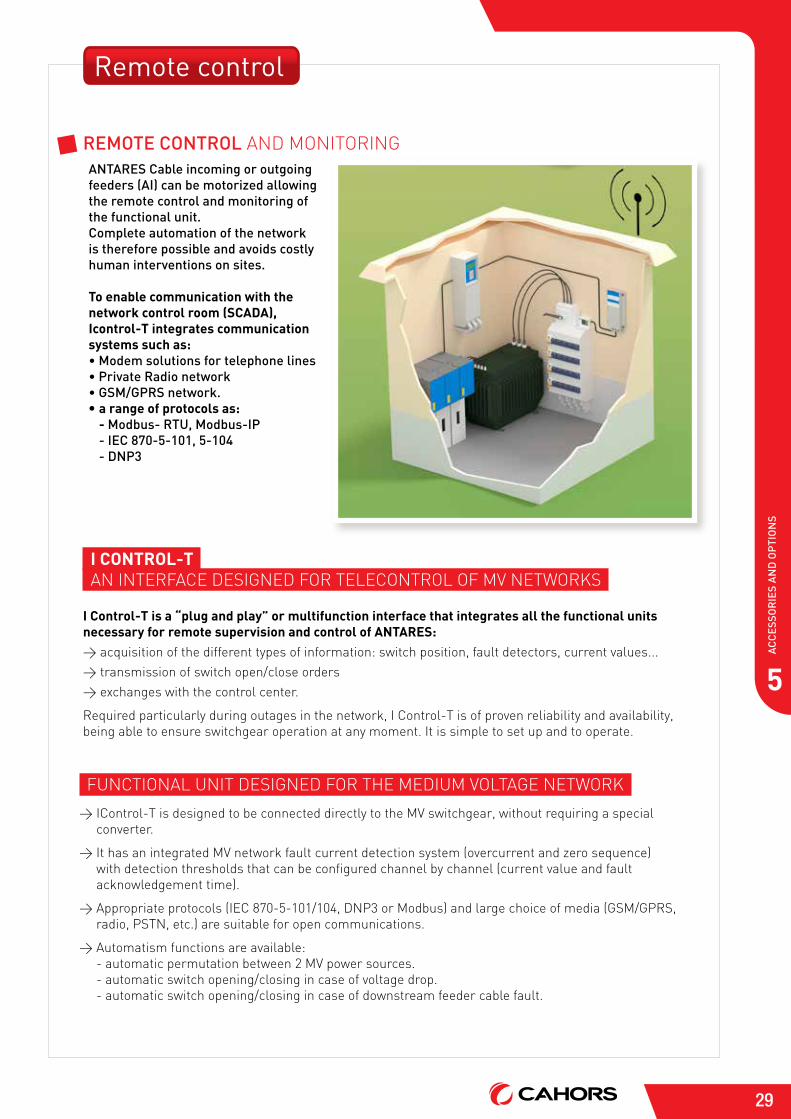
Remote control
antareS cable incoming or outgoing feeders (ai) can be motorized allowing the remote control and monitoring of the functional unit.complete automation of the network is therefore possible and avoids costly human interventions on sites.
To enable communication with the network control room (SCADA), Icontrol-T integrates communication systems such as:• modem solutions for telephone lines• Private radio network• GSm/GPrS network. • a range of protocols as:
- modbus- rtu, modbus-iP - iec 870-5-101, 5-104 - dnP3
remote control aNd MoNitoriNG
FUNctioNal UNit dEsiGNEd For thE MEdiUM VoltaGE NEtworK
> icontrol-t is designed to be connected directly to the MV switchgear, without requiring a special converter.
> it has an integrated MV network fault current detection system (overcurrent and zero sequence) with detection thresholds that can be configured channel by channel (current value and fault acknowledgement time).
> appropriate protocols (iEc 870-5-101/104, dNP3 or Modbus) and large choice of media (GsM/GPrs, radio, PstN, etc.) are suitable for open communications.
> automatism functions are available: - automatic permutation between 2 MV power sources. - automatic switch opening/closing in case of voltage drop. - automatic switch opening/closing in case of downstream feeder cable fault.
30
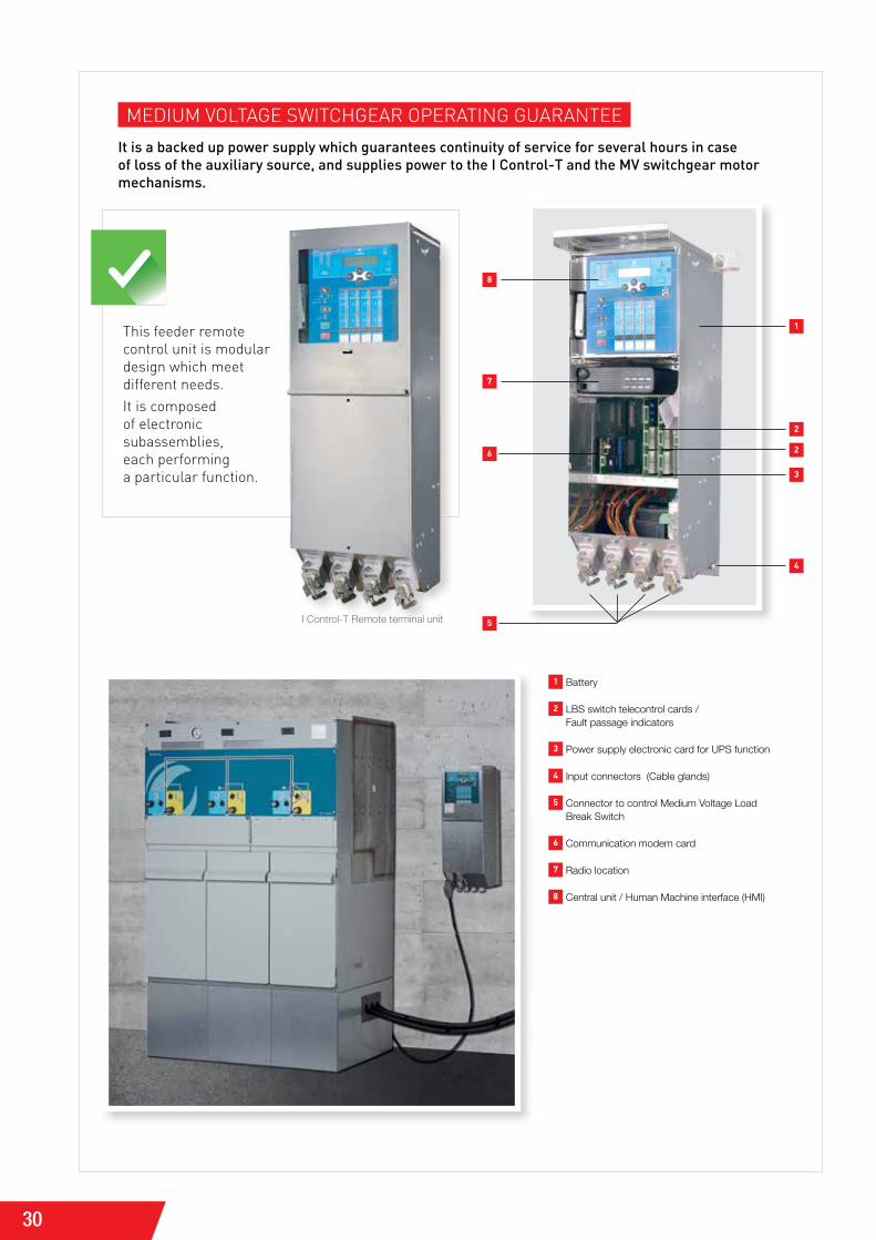
MEdiUM VoltaGE switchGEar oPEratiNG GUaraNtEE
it is a backed up power supply which guarantees continuity of service for several hours in case of loss of the auxiliary source, and supplies power to the i control-t and the mv switchgear motor mechanisms.
this feeder remote control unit is modular design which meet different needs.it is composed of electronic subassemblies, each performing a particular function.
I Control-T Remote terminal unit
1 Battery
2 LBS switch telecontrol cards / Fault passage indicators
3 Power supply electronic card for UPS function
4 Input connectors (Cable glands)
5 Connector to control Medium Voltage Load Break Switch
6 Communication modem card
7 Radio location
8 Central unit / Human Machine interface (HMI)
1
2
2
3
4
5
6
7
8
31
5
Ac
ces
sor
ies
An
d o
pti
on
s
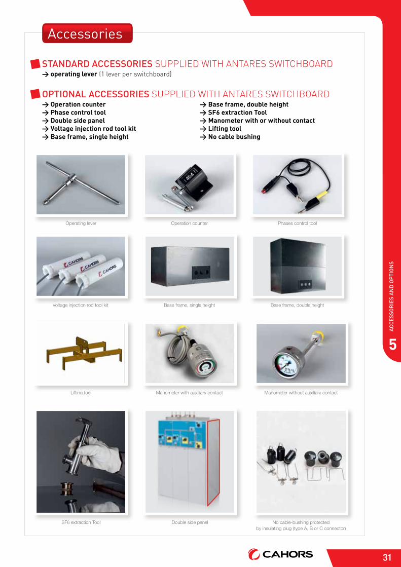
Standard acceSSorieS sUPPliEd with aNtarEs switchboard> operating lever (1 lever per switchboard)
oPtional acceSSorieS sUPPliEd with aNtarEs switchboard> Operation counter > Phase control tool > Double side panel > Voltage injection rod tool kit > Base frame, single height
> Base frame, double height > SF6 extraction Tool > Manometer with or without contact > Lifting tool > No cable bushing
Operating lever Operation counter
Base frame, single heightVoltage injection rod tool kit
Double side panel No cable-bushing protected by insulating plug (type A, B or C connector)
SF6 extraction Tool
Phases control tool
Base frame, double height
Manometer with auxiliary contact Manometer without auxiliary contactLifting tool
Accessories
32
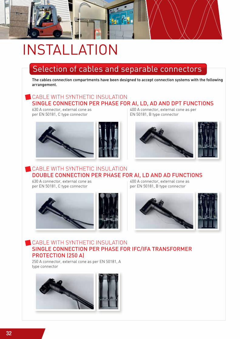
InSTALLATIOnSelection of cables and separable connectorsthe cables connection compartments have been designed to accept connection systems with the following arrangement.
cablE with syNthEtic iNsUlatioN SinGle connection Per PhaSe for ai, ld, ad and dPt functionS 630 a connector, external cone as per EN 50181, c type connector
400 a connector, external cone as per EN 50181, b type connector
cablE with syNthEtic iNsUlatioN double connection Per PhaSe for ai, ld and ad functionS 630 a connector, external cone as per EN 50181, c type connector
400 a connector, external cone as per EN 50181, b type connector
cablE with syNthEtic iNsUlatioN SinGle connection Per PhaSe for ifc/ifa tranSformer Protection (250 a) 250 a connector, external cone as per EN 50181, a type connector
33
6In
sta
llat
Ion
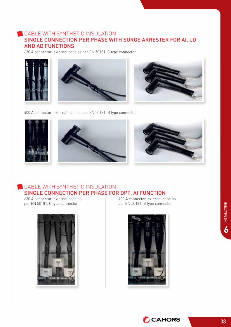
cablE with syNthEtic iNsUlatioN SinGle connection Per PhaSe with SurGe arreSter for ai, ld and ad functionS 630 a connector, external cone as per EN 50181, c type connector
400 a connector, external cone as per EN 50181, b type connector
cablE with syNthEtic iNsUlatioN SinGle connection Per PhaSe for dPt, ai function 630 a connector, external cone as per EN 50181, c type connector
400 a connector, external cone as per EN 50181, b type connector
34
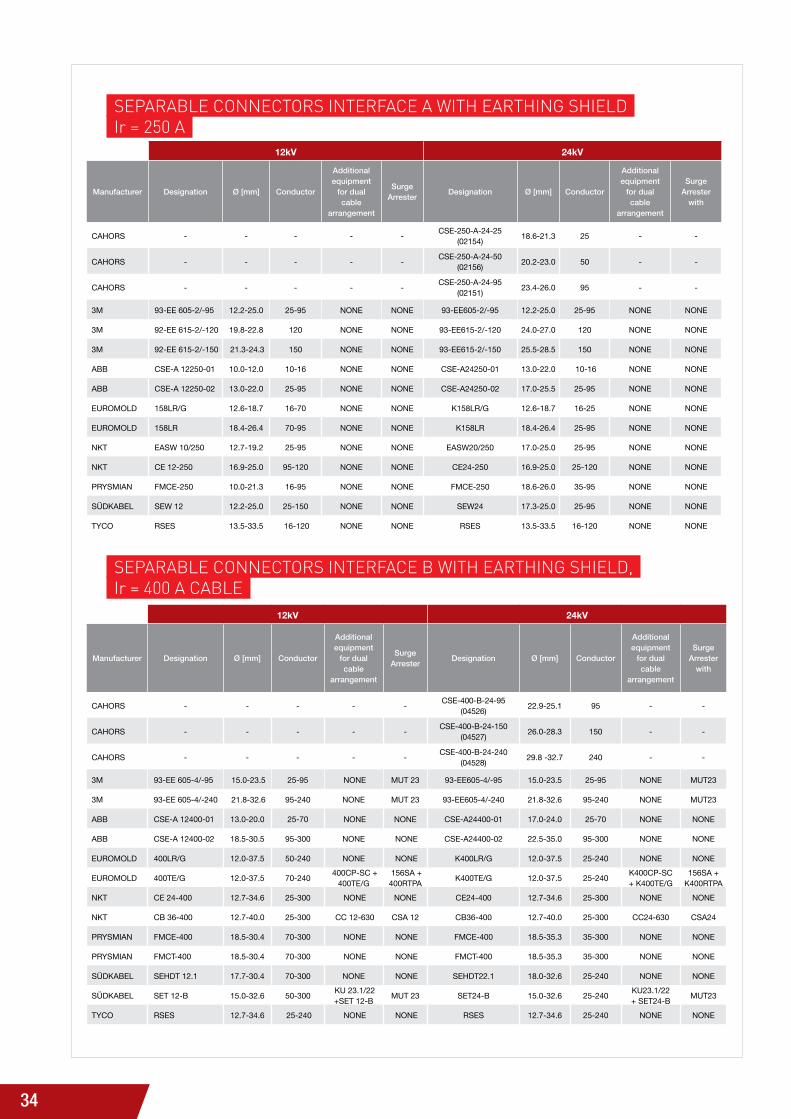
sEParablE coNNEctors iNtErFacE a with EarthiNG shiEldir = 250 a
sEParablE coNNEctors iNtErFacE b with EarthiNG shiEld, ir = 400 a cablE
12kV 24kV
Manufacturer Designation Ø [mm] Conductor
Additional equipment
for dual cable
arrangement
Surge Arrester
Designation Ø [mm] Conductor
Additional equipment
for dual cable
arrangement
Surge Arrester
with
CAHORS - - - - - CSE-250-A-24-25 (02154) 18.6-21.3 25 - -
CAHORS - - - - - CSE-250-A-24-50 (02156) 20.2-23.0 50 - -
CAHORS - - - - - CSE-250-A-24-95 (02151) 23.4-26.0 95 - -
3M 93-EE 605-2/-95 12.2-25.0 25-95 NONE NONE 93-EE605-2/-95 12.2-25.0 25-95 NONE NONE
3M 92-EE 615-2/-120 19.8-22.8 120 NONE NONE 93-EE615-2/-120 24.0-27.0 120 NONE NONE
3M 92-EE 615-2/-150 21.3-24.3 150 NONE NONE 93-EE615-2/-150 25.5-28.5 150 NONE NONE
ABB CSE-A 12250-01 10.0-12.0 10-16 NONE NONE CSE-A24250-01 13.0-22.0 10-16 NONE NONE
ABB CSE-A 12250-02 13.0-22.0 25-95 NONE NONE CSE-A24250-02 17.0-25.5 25-95 NONE NONE
EuROMOLD 158LR/G 12.6-18.7 16-70 NONE NONE K158LR/G 12.6-18.7 16-25 NONE NONE
EuROMOLD 158LR 18.4-26.4 70-95 NONE NONE K158LR 18.4-26.4 25-95 NONE NONE
NKT EASW 10/250 12.7-19.2 25-95 NONE NONE EASW20/250 17.0-25.0 25-95 NONE NONE
NKT CE 12-250 16.9-25.0 95-120 NONE NONE CE24-250 16.9-25.0 25-120 NONE NONE
PRYSMIAN FMCE-250 10.0-21.3 16-95 NONE NONE FMCE-250 18.6-26.0 35-95 NONE NONE
SüDKABEL SEW 12 12.2-25.0 25-150 NONE NONE SEW24 17.3-25.0 25-95 NONE NONE
TYCO RSES 13.5-33.5 16-120 NONE NONE RSES 13.5-33.5 16-120 NONE NONE
12kV 24kV
Manufacturer Designation Ø [mm] Conductor
Additional equipment
for dual cable
arrangement
Surge Arrester
Designation Ø [mm] Conductor
Additional equipment
for dual cable
arrangement
Surge Arrester
with
CAHORS - - - - - CSE-400-B-24-95 (04526) 22.9-25.1 95 - -
CAHORS - - - - - CSE-400-B-24-150 (04527) 26.0-28.3 150 - -
CAHORS - - - - - CSE-400-B-24-240 (04528) 29.8 -32.7 240 - -
3M 93-EE 605-4/-95 15.0-23.5 25-95 NONE MUT 23 93-EE605-4/-95 15.0-23.5 25-95 NONE MUT23
3M 93-EE 605-4/-240 21.8-32.6 95-240 NONE MUT 23 93-EE605-4/-240 21.8-32.6 95-240 NONE MUT23
ABB CSE-A 12400-01 13.0-20.0 25-70 NONE NONE CSE-A24400-01 17.0-24.0 25-70 NONE NONE
ABB CSE-A 12400-02 18.5-30.5 95-300 NONE NONE CSE-A24400-02 22.5-35.0 95-300 NONE NONE
EuROMOLD 400LR/G 12.0-37.5 50-240 NONE NONE K400LR/G 12.0-37.5 25-240 NONE NONE
EuROMOLD 400TE/G 12.0-37.5 70-240 400CP-SC + 400TE/G
156SA + 400RTPA K400TE/G 12.0-37.5 25-240 K400CP-SC
+ K400TE/G156SA +
K400RTPA
NKT CE 24-400 12.7-34.6 25-300 NONE NONE CE24-400 12.7-34.6 25-300 NONE NONE
NKT CB 36-400 12.7-40.0 25-300 CC 12-630 CSA 12 CB36-400 12.7-40.0 25-300 CC24-630 CSA24
PRYSMIAN FMCE-400 18.5-30.4 70-300 NONE NONE FMCE-400 18.5-35.3 35-300 NONE NONE
PRYSMIAN FMCT-400 18.5-30.4 70-300 NONE NONE FMCT-400 18.5-35.3 35-300 NONE NONE
SüDKABEL SEHDT 12.1 17.7-30.4 70-300 NONE NONE SEHDT22.1 18.0-32.6 25-240 NONE NONE
SüDKABEL SET 12-B 15.0-32.6 50-300 Ku 23.1/22 +SET 12-B MUT 23 SET24-B 15.0-32.6 25-240 Ku23.1/22
+ SET24-B MUT23
TYCO RSES 12.7-34.6 25-240 NONE NONE RSES 12.7-34.6 25-240 NONE NONE
35
AN
TAR
ES R
AN
GE
OF
FUN
CTI
ON
AL
UN
IT
6IN
STA
LLAT
ION
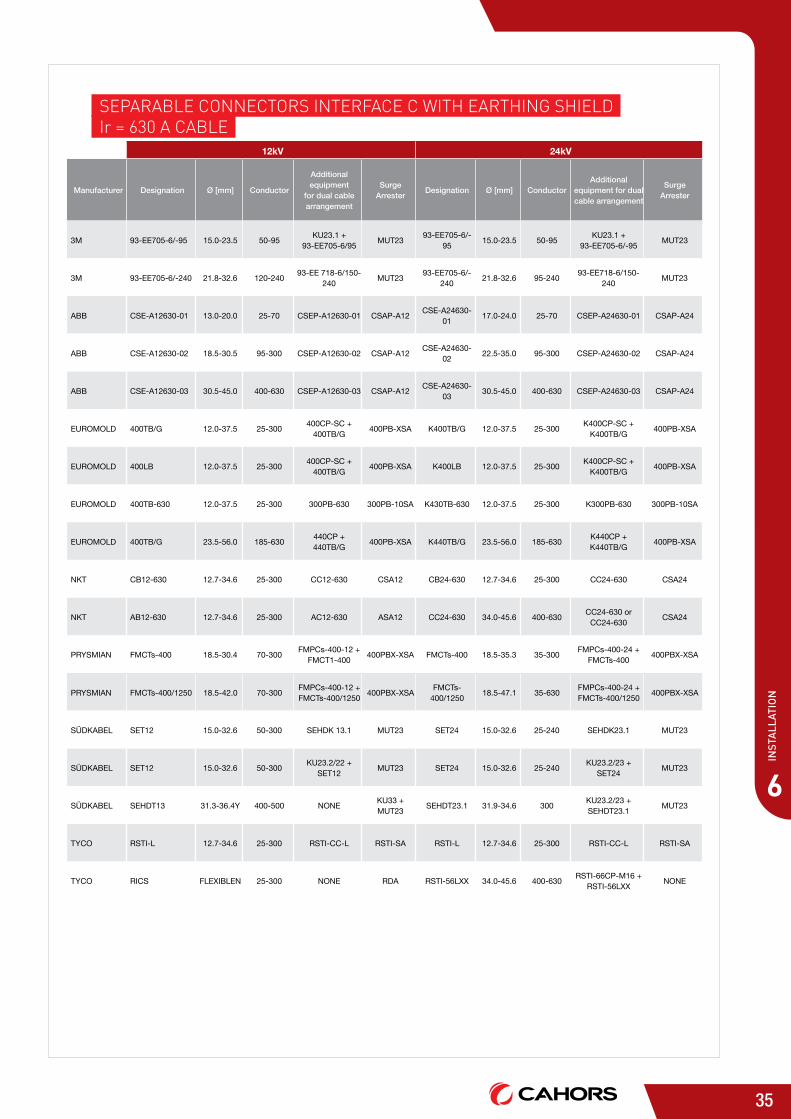
sEParablE coNNEctors iNtErFacE c with EarthiNG shiEldir = 630 a cablE
12kV 24kV
Manufacturer Designation Ø [mm] Conductor
Additional equipment
for dual cable arrangement
Surge Arrester
Designation Ø [mm] ConductorAdditional
equipment for dual cable arrangement
Surge Arrester
3M 93-EE705-6/-95 15.0-23.5 50-95 Ku23.1 + 93-EE705-6/95 MUT23 93-EE705-6/-
95 15.0-23.5 50-95 Ku23.1 + 93-EE705-6/-95 MUT23
3M 93-EE705-6/-240 21.8-32.6 120-240 93-EE 718-6/150-240 MUT23 93-EE705-6/-
240 21.8-32.6 95-240 93-EE718-6/150-240 MUT23
ABB CSE-A12630-01 13.0-20.0 25-70 CSEP-A12630-01 CSAP-A12 CSE-A24630-01 17.0-24.0 25-70 CSEP-A24630-01 CSAP-A24
ABB CSE-A12630-02 18.5-30.5 95-300 CSEP-A12630-02 CSAP-A12 CSE-A24630-02 22.5-35.0 95-300 CSEP-A24630-02 CSAP-A24
ABB CSE-A12630-03 30.5-45.0 400-630 CSEP-A12630-03 CSAP-A12 CSE-A24630-03 30.5-45.0 400-630 CSEP-A24630-03 CSAP-A24
EuROMOLD 400TB/G 12.0-37.5 25-300 400CP-SC + 400TB/G 400PB-XSA K400TB/G 12.0-37.5 25-300 K400CP-SC +
K400TB/G 400PB-XSA
EuROMOLD 400LB 12.0-37.5 25-300 400CP-SC + 400TB/G 400PB-XSA K400LB 12.0-37.5 25-300 K400CP-SC +
K400TB/G 400PB-XSA
EuROMOLD 400TB-630 12.0-37.5 25-300 300PB-630 300PB-10SA K430TB-630 12.0-37.5 25-300 K300PB-630 300PB-10SA
EuROMOLD 400TB/G 23.5-56.0 185-630 440CP + 440TB/G 400PB-XSA K440TB/G 23.5-56.0 185-630 K440CP +
K440TB/G 400PB-XSA
NKT CB12-630 12.7-34.6 25-300 CC12-630 CSA12 CB24-630 12.7-34.6 25-300 CC24-630 CSA24
NKT AB12-630 12.7-34.6 25-300 AC12-630 ASA12 CC24-630 34.0-45.6 400-630 CC24-630 or CC24-630 CSA24
PRYSMIAN FMCTs-400 18.5-30.4 70-300 FMPCs-400-12 + FMCT1-400 400PBX-XSA FMCTs-400 18.5-35.3 35-300 FMPCs-400-24 +
FMCTs-400 400PBX-XSA
PRYSMIAN FMCTs-400/1250 18.5-42.0 70-300 FMPCs-400-12 + FMCTs-400/1250 400PBX-XSA FMCTs-
400/1250 18.5-47.1 35-630 FMPCs-400-24 + FMCTs-400/1250 400PBX-XSA
SüDKABEL SET12 15.0-32.6 50-300 SEHDK 13.1 MUT23 SET24 15.0-32.6 25-240 SEHDK23.1 MUT23
SüDKABEL SET12 15.0-32.6 50-300 Ku23.2/22 + SET12 MUT23 SET24 15.0-32.6 25-240 Ku23.2/23 +
SET24 MUT23
SüDKABEL SEHDT13 31.3-36.4Y 400-500 NONE Ku33 + MUT23 SEHDT23.1 31.9-34.6 300 Ku23.2/23 +
SEHDT23.1 MUT23
TYCO RSTI-L 12.7-34.6 25-300 RSTI-CC-L RSTI-SA RSTI-L 12.7-34.6 25-300 RSTI-CC-L RSTI-SA
TYCO RICS FLEXIBLEN 25-300 NONE RDA RSTI-56LXX 34.0-45.6 400-630 RSTI-66CP-M16 + RSTI-56LXX NONE
36
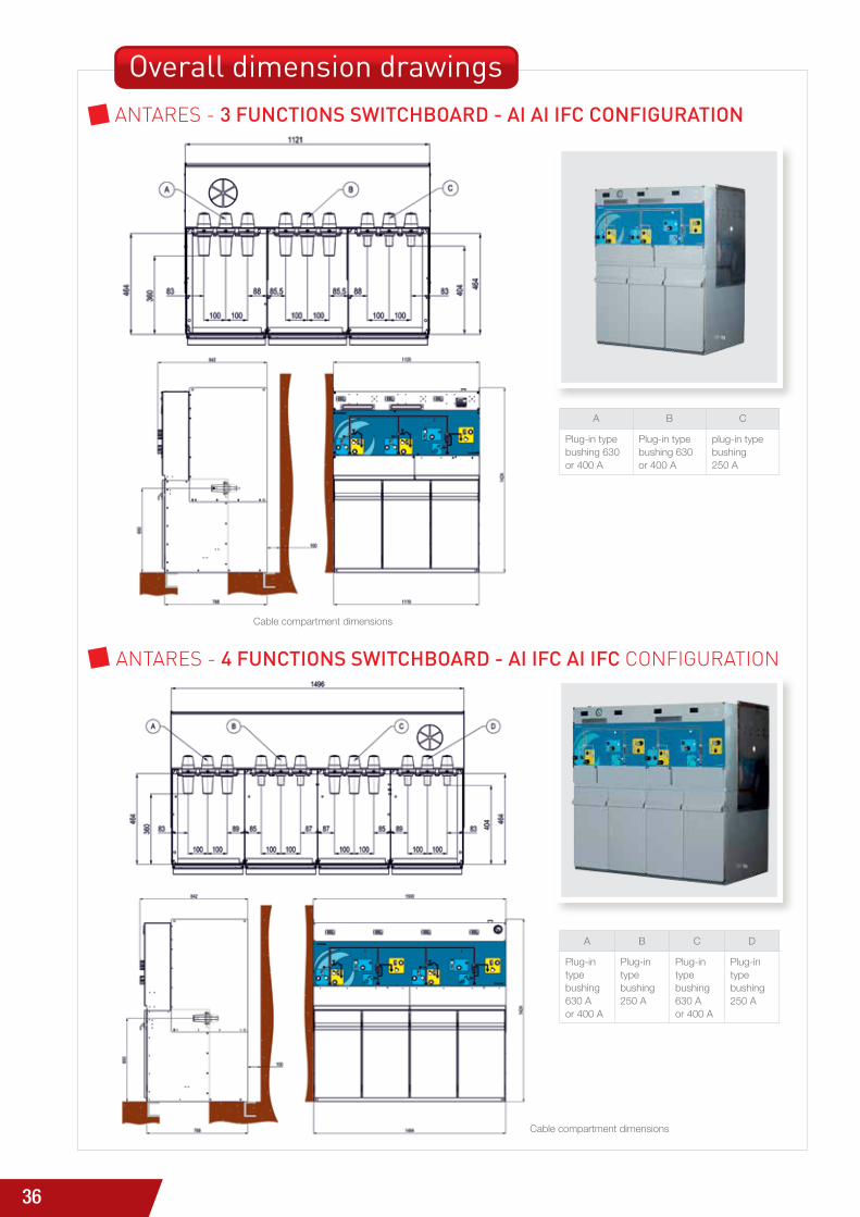
Overall dimension drawingsaNtarEs - 3 functionS Switchboard - ai ai ifc confiGuration
aNtarEs - 4 functionS Switchboard - ai ifc ai ifc coNFiGUratioN
Cable compartment dimensions
Cable compartment dimensions
A B C
Plug-in type bushing 630 or 400 A
Plug-in type bushing 630 or 400 A
plug-in type bushing 250 A
A B C D
Plug-in type bushing 630 A or 400 A
Plug-in type bushing 250 A
Plug-in type bushing 630 A or 400 A
Plug-in type bushing 250 A

37
AN
TAR
ES R
AN
GE
OF
FUN
CTI
ON
AL
UN
IT
6IN
STA
LLAT
ION
aNtarEs - 3 functionS Switchboard - ai dPt ai confiGuration
aNtarEs – 4 functionS Switchboard - ai dPt ai ai confiGuration
Cable compartment dimensions
Cable compartment dimensions
A B C D
Plug-in type bushing 630 or 400 A
Plug-in type bushing 630 or 400 A
Plug-in type bushing 630 or 400 A
Plug-in type bushing 630 or 400 A
A B C D
Plug-in type bushing 630 or 400 A
Plug-in type bushing 630 or 400 A
Plug-in type bushing 630 or 400 A
Plug-in type bushing 630 or 400 A
38
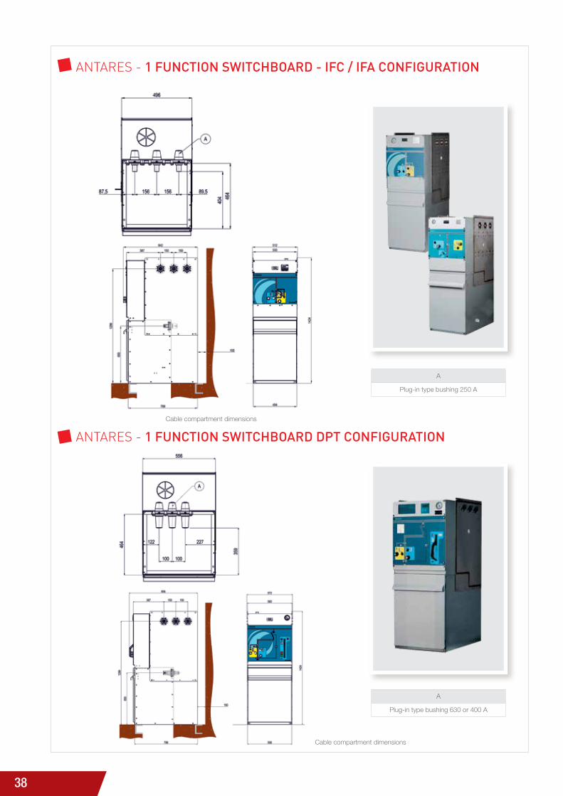
aNtarEs - 1 function Switchboard - ifc / ifa confiGuration
aNtarEs - 1 function Switchboard dPt confiGuration
Cable compartment dimensions
Cable compartment dimensions
A
Plug-in type bushing 250 A
A
Plug-in type bushing 630 or 400 A
39
AN
TAR
ES R
AN
GE
OF
FUN
CTI
ON
AL
UN
IT
6IN
STA
LLAT
ION
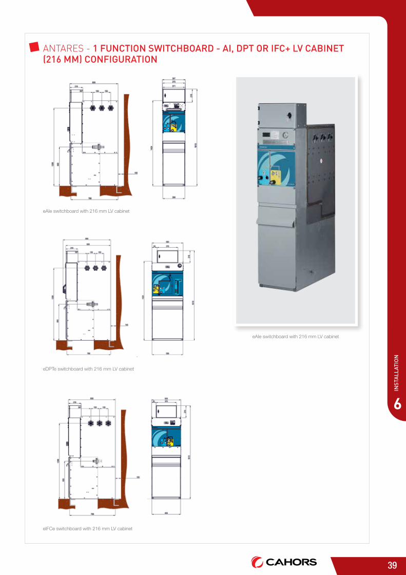
aNtarEs - 1 function Switchboard - ai, dPt or ifc+ lv cabinet (216 mm) confiGuration
eAIe switchboard with 216 mm LV cabinet
eAIe switchboard with 216 mm LV cabinet
eDPTe switchboard with 216 mm LV cabinet
eIFCe switchboard with 216 mm LV cabinet
40
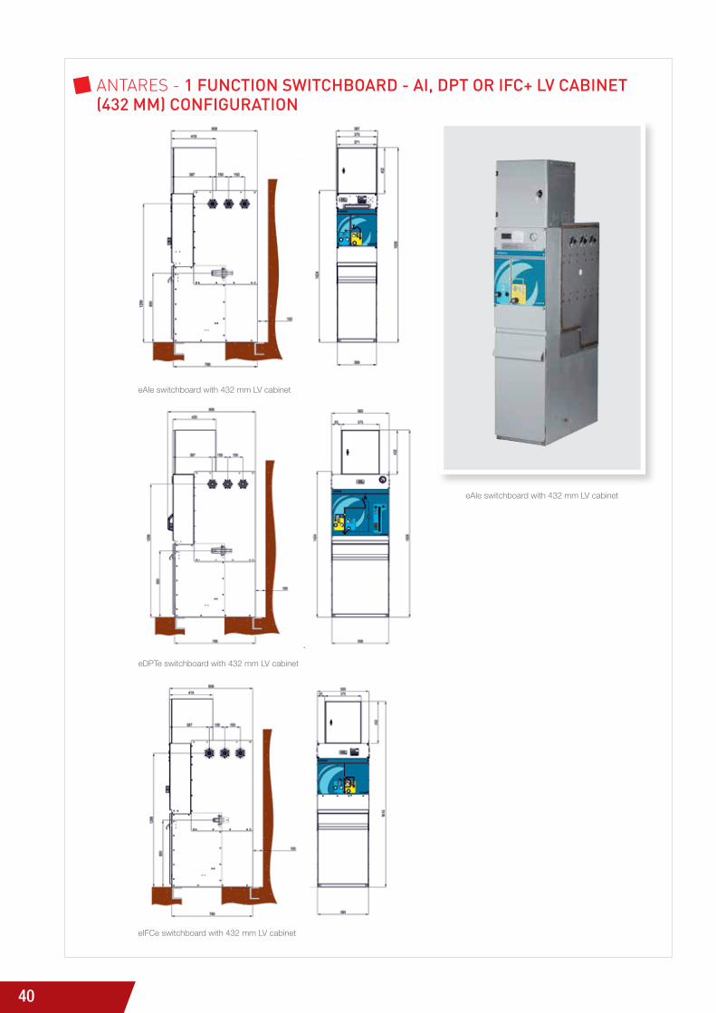
aNtarEs - 1 function Switchboard - ai, dPt or ifc+ lv cabinet (432 mm) confiGuration
eAIe switchboard with 432 mm LV cabinet
eAIe switchboard with 432 mm LV cabinet
eDPTe switchboard with 432 mm LV cabinet
eIFCe switchboard with 432 mm LV cabinet
41
AN
TAR
ES R
AN
GE
OF
FUN
CTI
ON
AL
UN
IT
6IN
STA
LLAT
ION
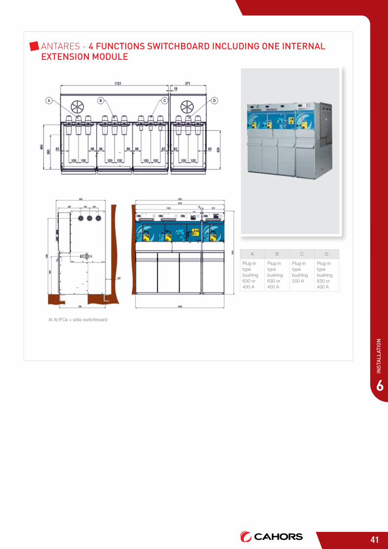
AI AI IFCe + eAIe switchboard
aNtarEs - 4 functionS Switchboard includinG one internal extenSion module
A B C D
Plug-in type bushing 630 or 400 A
Plug-in type bushing 630 or 400 A
Plug-in type bushing 250 A
Plug-in type bushing 630 or 400 A
42
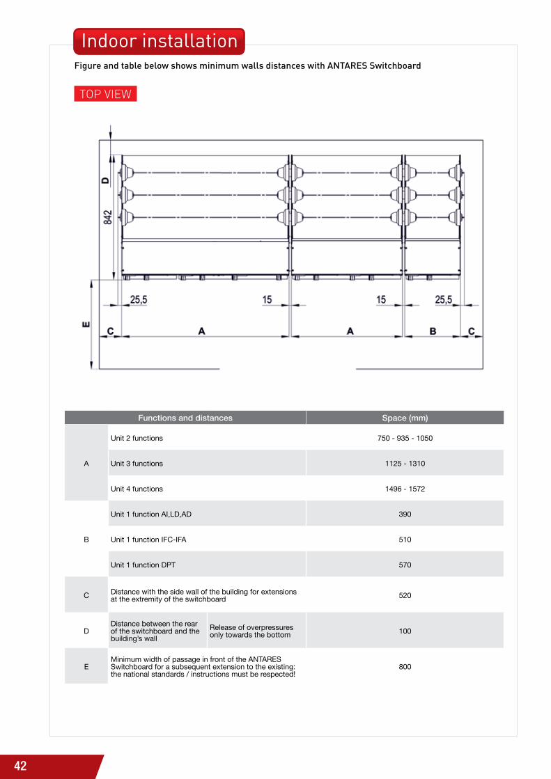
Functions and distances Space (mm)
A
unit 2 functions 750 - 935 - 1050
unit 3 functions 1125 - 1310
unit 4 functions 1496 - 1572
B
unit 1 function AI,LD,AD 390
unit 1 function IFC-IFA 510
unit 1 function DPT 570
C Distance with the side wall of the building for extensions at the extremity of the switchboard 520
DDistance between the rear of the switchboard and the building’s wall
Release of overpressures only towards the bottom 100
EMinimum width of passage in front of the ANTARES Switchboard for a subsequent extension to the existing: the national standards / instructions must be respected!
800
Indoor installation figure and table below shows minimum walls distances with antareS Switchboard
toP ViEw
43
AN
TAR
ES R
AN
GE
OF
FUN
CTI
ON
AL
UN
IT
6IN
STA
LLAT
ION
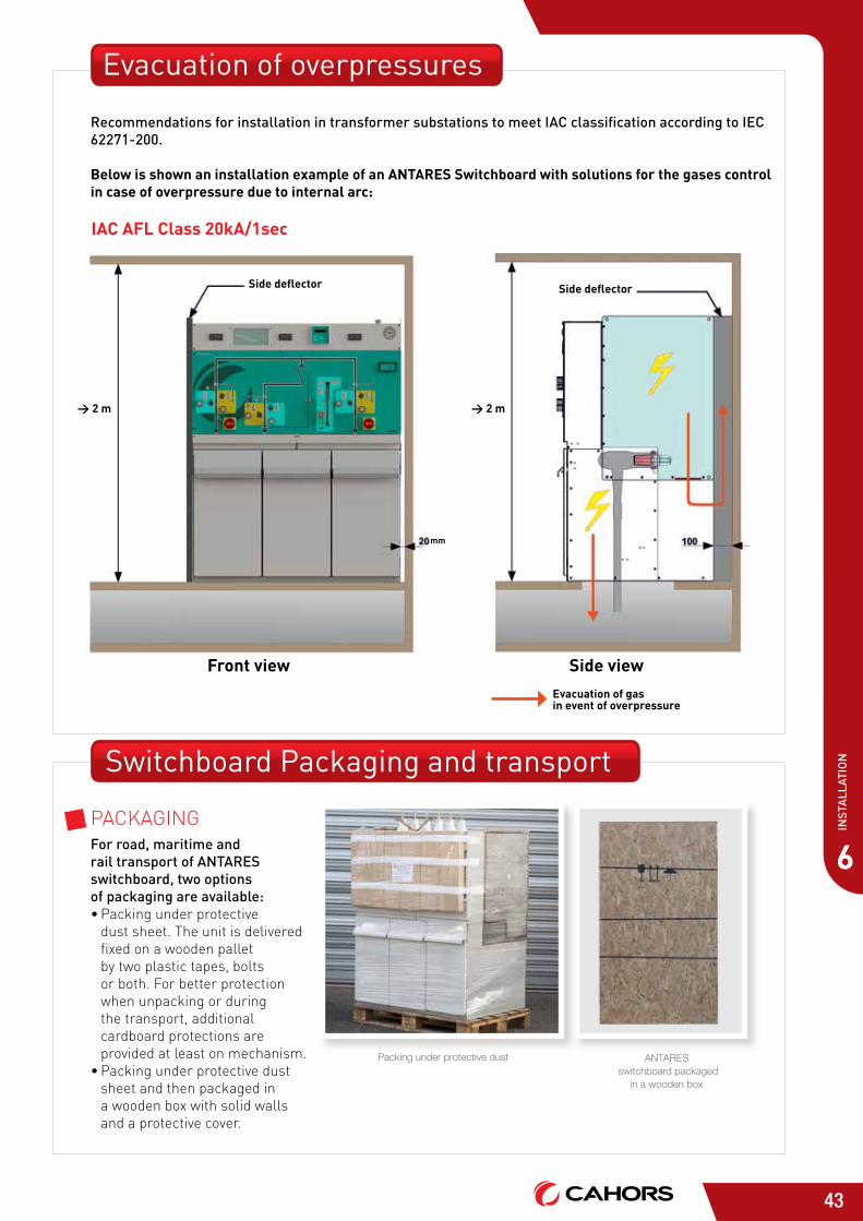
Evacuation of overpressures
recommendations for installation in transformer substations to meet iac classification according to iec 62271-200.
Below is shown an installation example of an ANTARES Switchboard with solutions for the gases control in case of overpressure due to internal arc:
IAC AFL Class 20kA/1sec
1 or 2 side deflector
Front view
> 2 m
mm
Side deflector
Side viewEvacuation of gas in event of overpressure
Switchboard Packaging and transport
PacKaGiNG for road, maritime and rail transport of antareS switchboard, two options of packaging are available:• Packing under protective
dust sheet. the unit is delivered fixed on a wooden pallet by two plastic tapes, bolts or both. For better protection when unpacking or during the transport, additional cardboard protections are provided at least on mechanism.
• Packing under protective dust sheet and then packaged in a wooden box with solid walls and a protective cover.
ANTARES switchboard packaged
in a wooden box
Packing under protective dust
> 2 m
Side deflector
44
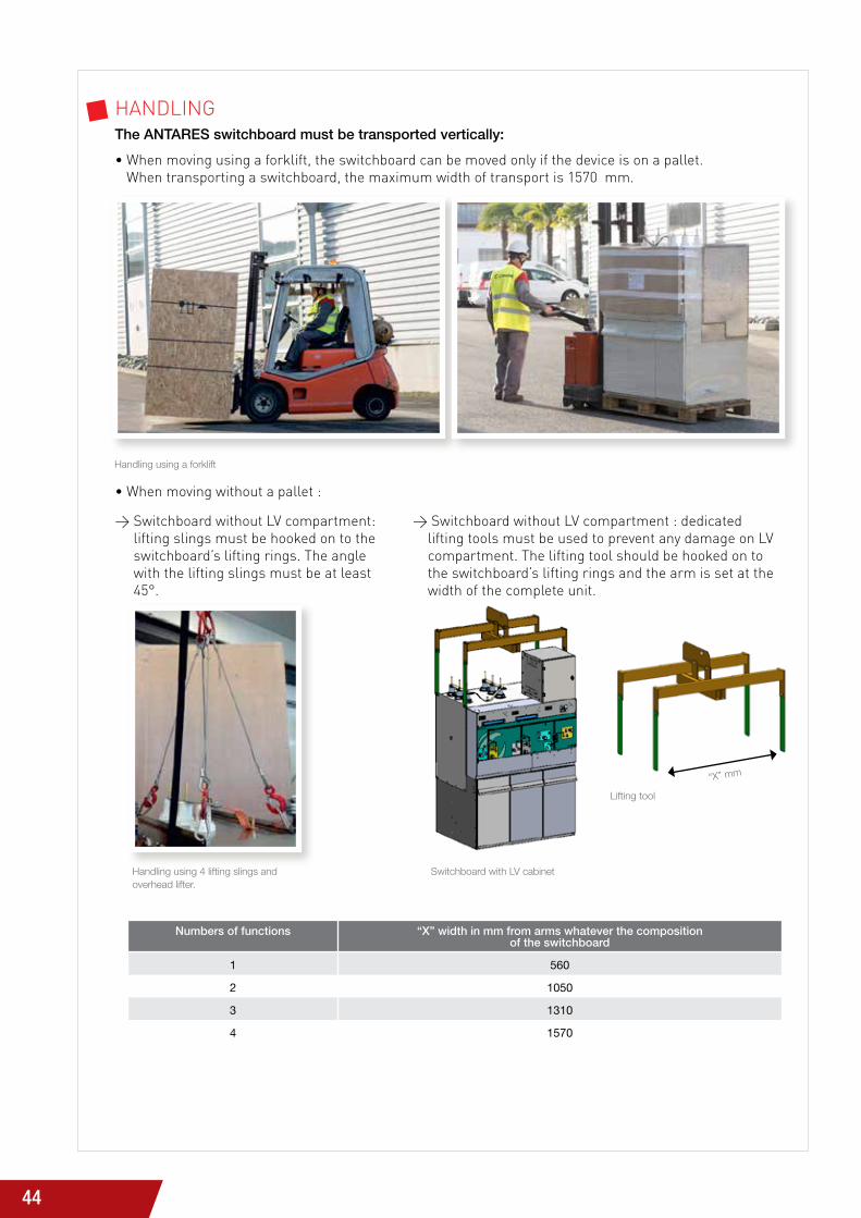
Handling using 4 lifting slings and overhead lifter.
Numbers of functions “X” width in mm from arms whatever the composition of the switchboard
1 560
2 1050
3 1310
4 1570
Handling using a forklift
> switchboard without lV compartment: lifting slings must be hooked on to the switchboard’s lifting rings. the angle with the lifting slings must be at least 45°.
> switchboard without lV compartment : dedicated lifting tools must be used to prevent any damage on lV compartment. the lifting tool should be hooked on to the switchboard’s lifting rings and the arm is set at the width of the complete unit.
haNdliNG The ANTARES switchboard must be transported vertically:
• when moving using a forklift, the switchboard can be moved only if the device is on a pallet. when transporting a switchboard, the maximum width of transport is 1570 mm.
• when moving without a pallet :
Switchboard with LV cabinet
Lifting tool
“X” mm

45
7
An
tAr
es &
su
stA
inA
ble
dev
elo
pm
ent
our coMMitMENts on the basis of our membership of the Global Compact (january 2013) and driven forward by our generation contract, signed in december 2013, we have set out our corporate responsibility strategy for all the companies in the Groupe cahors.
PROMOTInG HEALTH And SAfETY iN thE worKPlacEthis commitment shines through the sheer number of ohsas 18001 certificates our Group subsidiaries have been awarded, as well as through increased ergonomics and a stress and hardship inventory.
CLIEnTS And SuSTAInAbLE iNNoVatioNWe are committed to consistently increasing the number of innovative and environmentally beneficial services we can offer:
• Eco-designed products, to reduce environmental impact of the products during their lifetime
• End-of life management for our products to reduce greenhouse effect gases related to sF6
• solutions to connect renewable energies to the electrical networks
AnTARES® & SuSTAInAbLE dEVELOPMEnT
KEEPiNG qUality aNd thE ENViroNMENt at thE hEart oF oUr coMPaNy cUltUrE
we pull out all the stops to control and limit the environmental impact of our activities. both management and the production process are subject to continuous efforts for improvement. all of the medium voltage companies within the Groupe cahorS are iSo 9001 certified, and the largest are iSo 14001 certified as well.
sUstaiNablE dEVEloPMENt
46
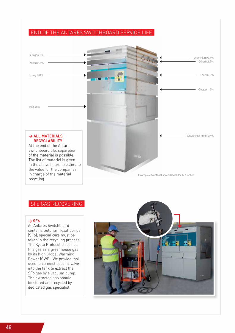
SF6 gas 1%Aluminium 0,8%
Others 2,6%
Steel 6,2%
Copper 16%
Galvanised sheet 37%
Plastic 2,7%
Epoxy 6,6%
Inox 28%
Example of material spreadsheet for AI function
> SF6as antares switchboard contains sulphur hexafluoride (sF6), special care must be taken in the recycling process. the Kyoto Protocol classifies this gas as a greenhouse gas by its high Global warming Power (GwP). we provide tool used to connect specific valve into the tank to extract the sF6 gas by a vacuum pump. the extracted gas should be stored and recycled by dedicated gas specialist.
ENd oF thE aNtarEs switchboard sErVicE liFE
sF6 Gas rEcoVEriNG
> ALL MATERIALS RECYCLABILITY
at the end of the antares switchboard life, separation of the material is possible. the list of materiel is given in the above figure to estimate the value for the companies in charge of the material recycling.

47
AN
TAR
ES R
AN
GE
OF
FUN
CTI
ON
AL
UN
IT
med
ium
vo
lta
Ge
Ser
vic
eS
8
MEdIuM VOLTAGE SERVICES
sPEciFic sErVicEsthe global expertise of cahorS in the field of network architecture ensures its customers are provided with the following services:
> Analysing the operating systems.
> Offering the most suitable technical solutions.
> Training operators on standard evolutions, operation and maintenance of products.
> CAHORS “services”: to meet your expectations, with experts at your disposal, and the benefit of a local sales presence.
> CAHORS positions itself as close as possible to its customers.
Offering advice and technical assistance in managing projectsto customers
Training about operation and maintenance of the products and applicable standards provided by our two certified training organisations
www.groupe-cahors.com
AFRICACAHORS SOUTH AFRICA Tel: +27 (0)51 534 1651 Email: [email protected]
CAHORS GUINEATel: +22 (0)4 664 28 05 28 Email: [email protected]
CAHORS MALI Tel: +22 (0)3 44 38 00 43 Email: [email protected]
CAHORS MOROCCOTel: +212 522 53 63 10 Email: [email protected]
CAHORS TUNISIATel.: +216 71 854 130 Email: [email protected]
SOUTH AMERICACAHORS URUGUAY Tel: +598 (2) 368 9800 Email: [email protected]
ASIACAHORS CHINATel: +86 532 8690 7086 Email: [email protected]
CAHORS INDIATel: +91 (0) 20 66 49 53 00 Email: [email protected]
EUROPECAHORS SPAINTel: +34 972 52 60 00 Email: [email protected]
CAHORS FRANCE Tel: +33 (0)5 62 91 44 66 Email: [email protected]
For all other countriesCAHORS INTERNATIONALTel: +33 (0)5 65 35 82 01 Email: [email protected] N
on b
indi
ng d
ocum
ent 0
1/16
- R
éalis
atio
n : L
. Bon
hom
me.
Related Documents