D00001680 • Rev 2.0 thisisant.com SoftDevice Specification S332 SoftDevice v2.0

Welcome message from author
This document is posted to help you gain knowledge. Please leave a comment to let me know what you think about it! Share it to your friends and learn new things together.
Transcript
D00001680 • Rev 2.0 thisisant.com
SoftDevice Specification
S332 SoftDevice v2.0
Page 2 of 102 S332 SoftDevice Specification, Rev 2.0
D00001680 thisisant.com
Copyright Information and Usage Notice
This information disclosed herein is the exclusive property of Dynastream Innovations Inc. and Nordic Semiconductor ASA.
No part of this publication may be reproduced or transmitted in any form or by any means including electronic storage,
reproduction, execution or transmission without the prior written consent of Dynastream Innovations Inc. The recipient of
this document by its retention and use agrees to respect the copyright of the information contained herein.
The information contained in this document is subject to change without notice and should not be construed as a
commitment by Dynastream Innovations Inc. unless such commitment is expressly given in a covering document.
The Dynastream Innovations Inc. ANT Products described by the information in this document are not designed, intended,
or authorized for use as components in systems intended for surgical implant into the body, or other applications intended
to support or sustain life, or for any other application in which the failure of the Dynastream product could create a situation
where personal injury or death may occur. If you use the Products for such unintended and unauthorized applications, you
do so at your own risk and you shall indemnify and hold Dynastream and its officers, employees, subsidiaries, affiliates, and
distributors harmless against all claims, costs, damages, and expenses, and reasonable attorney fees arising out of, directly
or indirectly, any claim of personal injury or death associated with such unintended or unauthorized use, even if such claim
alleges that Dynastream was negligent regarding the design or manufacture of the Product.
©2016 Dynastream Innovations Inc. All Rights Reserved.

S332 SoftDevice Specification, Rev 2.0 Page 3 of 102
D00001680 thisisant.com
Revision History
Revision Effective Date Description
1.0 May 2016 Initial SDS creation
2.0 September 2016
New ANT Features: High Duty Search, Time Sync, PA/LNA Support
New BLE Features: Configurable ATT MTU, Connection Event Length
Extension, LE Ping, LE Privacy
Page 4 of 102 S332 SoftDevice Specification, Rev 2.0
D00001680 thisisant.com
Table of Contents
1 S332 SoftDevice ........................................................................................................................................................ 11
2 Documentation .......................................................................................................................................................... 13
3 Product Overview ...................................................................................................................................................... 14
4 Application Programming Interface (API) .............................................................................................................. 15
4.1 Events – SoftDevice to application ............................................................................................................... 15
4.2 Error handling ............................................................................................................................................ 15
5 SoftDevice Manager .................................................................................................................................................. 16
5.1 SoftDevice enable and disable ..................................................................................................................... 16
5.1.1 ANT License Key .......................................................................................................................... 16
5.2 Clock source ............................................................................................................................................... 16
5.3 Power management .................................................................................................................................... 17
5.4 Memory isolation and runtime protection ..................................................................................................... 17
6 System on Chip (SoC) Library .................................................................................................................................. 20
7 System on Chip resource requirements .................................................................................................................. 21
7.1 Hardware peripherals ................................................................................................................................. 21
7.2 Application signals – Software Interrupts (SWI) ........................................................................................... 24
7.3 Programmable Peripheral Interconnect (PPI) ............................................................................................... 24
7.4 SVC number ranges .................................................................................................................................... 25
7.5 Peripheral runtime protection ...................................................................................................................... 25
7.6 External and miscellaneous requirements .................................................................................................... 26
8 Flash memory API ..................................................................................................................................................... 27
8.1 Using flash with ANT activity ....................................................................................................................... 27
8.2 Using flash with BLE activity ........................................................................................................................ 27
9 Multiprotocol support ............................................................................................................................................... 29
9.1 Non-concurrent multiprotocol implementation .............................................................................................. 29
9.2 Concurrent multiprotocol implementation using the Radio Timeslot API ........................................................ 29
9.2.1 Request types .............................................................................................................................. 29
9.2.2 Request priorities ......................................................................................................................... 29
9.2.3 Timeslot length ............................................................................................................................ 30
9.2.4 Scheduling ................................................................................................................................... 30
9.2.5 Performance considerations .......................................................................................................... 30
9.2.6 Radio Timeslot API ....................................................................................................................... 31
9.3 Radio Timeslot API usage scenarios ............................................................................................................ 33
9.3.1 Complete session example ............................................................................................................ 33
9.3.2 Blocked timeslot scenario ............................................................................................................. 34
9.3.3 Cancelled timeslot scenario ........................................................................................................... 35
9.3.4 Radio Timeslot extension example ................................................................................................ 35
10 ANT Protocol Stack ................................................................................................................................................... 37
S332 SoftDevice Specification, Rev 2.0 Page 5 of 102
D00001680 thisisant.com
10.1 Overview ............................................................................................................................................... 37
10.2 ANT feature support .............................................................................................................................. 37
10.2.1 Search Uplink ............................................................................................................................... 37
10.2.2 Group Transmitter Initiation.......................................................................................................... 37
10.2.3 High Duty Search ......................................................................................................................... 38
10.2.4 Time Sync .................................................................................................................................... 38
11 Bluetooth® low energy protocol stack .................................................................................................................... 39
11.1 Profile and service support ..................................................................................................................... 39
11.2 Bluetooth® low energy features .............................................................................................................. 41
11.3 Limitations on procedure concurrency ..................................................................................................... 44
11.4 BLE role configuration ............................................................................................................................ 44
12 Radio Notification ..................................................................................................................................................... 46
12.1 Radio Notification Signals ....................................................................................................................... 46
12.2 ANT traffic Radio Notifications ................................................................................................................ 48
12.2.1 ANT Broadcast traffic ................................................................................................................... 48
12.2.2 ANT Burst traffic .......................................................................................................................... 49
12.3 BLE traffic Radio Notifications ................................................................................................................. 51
12.3.1 Radio Notification on connection events as a Central ..................................................................... 52
12.3.2 Radio Notification on connection events as a Peripheral ................................................................. 54
12.3.3 Radio Notification with concurrent Peripheral and central connection events ................................... 55
12.3.4 Radio Notification with Connection Event Length Extension ............................................................ 56
12.4 Power Amplifier and Low Noise Amplifier control configuration (PA/LNA) .................................................. 57
13 Master Boot Record and bootloader ........................................................................................................................ 59
13.1 Master Boot Record ............................................................................................................................... 59
13.2 Bootloader ............................................................................................................................................. 59
13.3 Master Boot Record (MBR) and SoftDevice reset procedure ..................................................................... 60
13.4 Master Boot Record (MBR) and SoftDevice initialization procedure ........................................................... 61
14 SoftDevice information structure ............................................................................................................................ 62
15 SoftDevice memory usage........................................................................................................................................ 63
15.1 Memory resource map and usage ........................................................................................................... 63
15.1.1 Memory resource requirements ..................................................................................................... 64
15.2 ANT Channel Configuration .................................................................................................................... 65
15.3 Attribute table size ................................................................................................................................. 65
15.4 Role configuration .................................................................................................................................. 66
15.5 Security configuration ............................................................................................................................ 66
15.6 Vendor specific UUID counts .................................................................................................................. 66
16 Scheduling ................................................................................................................................................................. 67
16.1 SoftDevice timing-activities and priorities ................................................................................................ 67
16.2 BLE Initiator timing ................................................................................................................................ 68
16.3 BLE Connection timing as a central ......................................................................................................... 70
Page 6 of 102 S332 SoftDevice Specification, Rev 2.0
D00001680 thisisant.com
16.4 BLE Scanner timing ................................................................................................................................ 71
16.5 BLE Advertiser (connectable and non-connectable) timing ....................................................................... 72
16.6 BLE Peripheral connection setup and connection timing ........................................................................... 73
16.7 Connection timing with Connection Event Length Extension ..................................................................... 74
16.8 Flash API timing .................................................................................................................................... 74
16.9 Timeslot API timing ............................................................................................................................... 75
16.10 BLE suggested intervals and windows ..................................................................................................... 75
17 Interrupt model and processor availability ............................................................................................................ 78
17.1 Exception model .................................................................................................................................... 78
17.1.1 Interrupt forwarding to the application .......................................................................................... 78
17.1.2 Interrupt latency due to System on Chip (SoC) framework ............................................................. 78
17.2 Interrupt priority levels .......................................................................................................................... 79
17.3 Processor usage patterns and availability ................................................................................................ 81
17.3.1 Flash API processor usage patterns ............................................................................................... 81
17.3.2 Radio Timeslot API processor usage patterns ................................................................................ 82
17.3.3 ANT processor usage patterns ...................................................................................................... 83
17.3.4 BLE processor usage patterns ....................................................................................................... 85
17.3.5 Interrupt latency when using multiple modules, channels, and roles ............................................... 90
18 BLE data throughput ................................................................................................................................................. 91
19 ANT power profiles.................................................................................................................................................... 94
19.1 Master Channel...................................................................................................................................... 94
19.2 Slave Channel ........................................................................................................................................ 95
20 BLE power profiles .................................................................................................................................................... 97
20.1 Advertising event ................................................................................................................................... 97
20.2 Peripheral connection event ................................................................................................................... 98
20.3 Scanning event ...................................................................................................................................... 99
20.4 Central connection event ....................................................................................................................... 100
21 SoftDevice identification and revision scheme ..................................................................................................... 101
21.1 MBR distribution and revision scheme .................................................................................................... 102
S332 SoftDevice Specification, Rev 2.0 Page 7 of 102
D00001680 thisisant.com
List of Figures
Figure 3-1. System on Chip application with the SoftDevice ....................................................................... 14
Figure 5-1. Memory region designation ..................................................................................................... 18
Figure 9-1. Complete Radio Timeslot session example ............................................................................... 34
Figure 9-2. Blocked timeslot scenario ........................................................................................................ 34
Figure 9-3. Cancelled Timeslot Scenario .................................................................................................... 35
Figure 9-4. Radio Timeslot Extension Example ........................................................................................... 36
Figure 10-1. ANT Stack Architecture .......................................................................................................... 37
Figure 11-1. SoftDevice stack architecture ................................................................................................. 39
Figure 12-1. Two Radio Events with ACTIVE and nACTIVE Signals ............................................................. 46
Figure 12-2. Two radio events where tgap is too small and the notification signals will not be available between the events ........................................................................................................................................ 47
Figure 12-3. ANT Broadcast with tndist >= 1740μs ...................................................................................... 48
Figure 12-4. ANT Broadcast with tndist = 800μs .......................................................................................... 49
Figure 12-5. ANT Burst with tndist >= 2680μs ............................................................................................. 49
Figure 12-6. ANT Burst with ndist = 1740μs .............................................................................................. 50
Figure 12-7. ANT Burst with ndist = 800μs ................................................................................................ 51
Figure 12-8. A BLE central link with multiple packet exchange per connection event ................................... 52
Figure 12-9. BLE Radio Notification signal in relation to a single active link ................................................. 53
Figure 12-10 BLE Radio Notification signal in relation to 3 active links ........................................................ 53
Figure 12-11. BLE Radio Notification signal when the number of active links as a Central is 2 ...................... 53
Figure 12-12. BLE Radio Notification signal in relation to 3 active connections as a Central while scanning ... 54
Figure 12-13. A BLE peripheral link with multiple packet exchange per connection event ............................. 54
Figure 12-14. Consecutive peripheral radio events with BLE Radio Notification signals ................................. 55
Figure 12-15. Example: the gap between the links as a Central and the Peripheral is too small to trigger the notification signal .............................................................................................................................. 56
Figure 12-16. Example: the gap between the links as a Central and the peripheral is sufficient to trigger the notification signal .............................................................................................................................. 56
Figure 12-17. Example: Extending the peripheral connection event is limited by the Radio Notification ........ 57
Figure 12-18. Example: The gaps between links as centrals are used to extend the connection events of the links. ................................................................................................................................................ 57
Figure 12-19. Example of timings when the PA/LNA control is enabled. The PA pin is configured active high, and the LNA pin is configured active low. ........................................................................................... 58
Figure 13-1. MBR, SoftDevice and bootloader architecture ......................................................................... 60
Figure 14-1. SoftDevice information structure ............................................................................................ 62
Figure 15-1. Memory Resource Map .......................................................................................................... 63
Figure 16-1. Initiator - first connection ...................................................................................................... 68
Figure 16-2. Initiator - one central connection running ............................................................................... 68
Figure 16-3. Initiator - free time due to disconnection ............................................................................... 69
Figure 16-4. Initiator - one or more connections as central ........................................................................ 69
Figure 16-5. Initiator - free time not enough ............................................................................................. 69
Page 8 of 102 S332 SoftDevice Specification, Rev 2.0
D00001680 thisisant.com
Figure 16-6. Initiator - fast connection ...................................................................................................... 70
Figure 16-7. Multilink scheduling - one or more connections as a central, factored intervals ........................ 70
Figure 16-8. Multilink scheduling - one or more connections as a central, unfactored intervals ..................... 70
Figure 16-9. Multilink scheduling with maximum connections as a central and minimum interval ................. 71
Figure 16-10. Multilink scheduling of connections as a central and interval > min ....................................... 71
Figure 16-11. Scanner timing - no active connections ................................................................................ 71
Figure 16-12. Scanner timing - one or more connections as a central ......................................................... 72
Figure 16-13. Scanner timing - always after connections ............................................................................ 72
Figure 16-14. Scanner timing - one connection, long window ..................................................................... 72
Figure 16-15. Advertiser ........................................................................................................................... 72
Figure 16-16. Advertiser collide ................................................................................................................. 73
Figure 16-17. Peripheral connection setup and connection ......................................................................... 73
Figure 16-18. Peripheral connection setup and connection with collision ..................................................... 73
Figure 16-19. Example: Multilink scheduling utilizing idle time between timing-events ................................. 74
Figure 16-20. Worst case collision of BLE roles .......................................................................................... 76
Figure 16-21. Three links running as a central and one peripheral .............................................................. 76
Figure 17-1. Exception model ................................................................................................................... 80
Figure 17-2. SoftDevice Exception examples (some priority levels left out for clarity) .................................. 80
Figure 17-3. Flash API activity (some priority levels left out for clarity) ....................................................... 81
Figure 17-4. Radio Timeslot API activity (some priority levels left out for clarity) ......................................... 82
Figure 17-5. ANT Protocol Event ............................................................................................................... 83
Figure 17-6. Advertising events (some of the priority levels left out for clarity)............................................ 85
Figure 17-7. Peripheral connection events (some of the priority levels left out for clarity) ............................ 86
Figure 17-8. Scanning or initiating (some of the priority levels left out for clarity) ....................................... 88
Figure 17-9. Central Connection events (some of the priority levels left out for clarity) ................................ 89
Figure 19-1. Master Channel Power and CPU Profile................................................................................... 94
Figure 19-2. Slave Channel Power and CPU Profile ..................................................................................... 95
Figure 20-1. Advertising event .................................................................................................................. 97
Figure 20-2. Peripheral connection event................................................................................................... 98
Figure 20-3. Scanning event ..................................................................................................................... 99
Figure 20-4. Central connection event ...................................................................................................... 100
List of Tables
Table 1-1. Summary of key features and applications ................................................................................ 11
Table 2-1. S332 SoftDevice core documentation ........................................................................................ 13
Table 6-1. System on Chip features .......................................................................................................... 20
Table 7-1. Hardware access type definitions .............................................................................................. 21
Table 7-2. Peripheral protection and usage by SoftDevice .......................................................................... 21
Table 7-3. Allocation of Software Interrupt vectors to SoftDevice signals .................................................... 24
Table 7-4. Assigning PPI channels between the application and SoftDevice ................................................. 25
S332 SoftDevice Specification, Rev 2.0 Page 9 of 102
D00001680 thisisant.com
Table 7-5. Assigning preprogrammed channels between the application and SoftDevice .............................. 25
Table 7-6. Assigning PPI groups between the application and SoftDevice ................................................... 25
Table 7-7. SVC number allocation ............................................................................................................. 25
Table 8-1. Behaviour with ANT traffic and concurrent flash write/erase ...................................................... 27
Table 8-2. Behaviour with BLE traffic and concurrent flash write/erase ....................................................... 28
Table 9-1. API calls .................................................................................................................................. 31
Table 9-2. Radio Timeslot events .............................................................................................................. 31
Table 9-3. Radio Timeslot signals .............................................................................................................. 32
Table 9-4. Signal handler action return values ........................................................................................... 32
Table 11-1. Supported profiles and services .............................................................................................. 39
Table 11-2. API features in the BLE stack .................................................................................................. 41
Table 11-3. GAP features in the BLE stack ................................................................................................. 41
Table 11-4. GATT features in the BLE stack ............................................................................................... 42
Table 11-5. Security Manager (SM) features in the BLE stack ..................................................................... 42
Table 11-6. Attribute Protocol (ATT) features in the BLE stack ................................................................... 43
Table 11-7. Controller, Link Layer (LL) features in the BLE stack ................................................................ 43
Table 11-8. Proprietary features in the BLE stack ....................................................................................... 44
Table 11-9. Limitations on procedure concurrency ..................................................................................... 44
Table 12-1. Notation and terminology for the Radio Notification used in this chapter ................................... 47
Table 12-2. BLE Radio Notification timing ranges ....................................................................................... 51
Table 12-3. Maximum Peripheral packet transfer per BLE Radio Event for given combinations of Radio Notification distances and connection intervals. Assumes full length packets and full-duplex, HIGH/HIGH BLE bandwidth configuration. ............................................................................................................ 55
Table 15-1. S332 Memory resource requirements for flash ......................................................................... 64
Table 15-2. S332 Memory resource requirements for RAM ......................................................................... 64
Table 15-3. S332 Memory resource requirements for call stack .................................................................. 65
Table 16-1. Scheduling priorities ............................................................................................................... 67
Table 16-2. Peripheral role timing ranges .................................................................................................. 73
Table 17-1. Additional latency due to SoftDevice and MBR forwarding interrupts......................................... 78
Table 17-2. Processor usage for the flash API............................................................................................ 81
Table 17-3. Processor usage for the Radio Timeslot API ............................................................................. 83
Table 17-4. Processor usage latency when connected (ANT) ...................................................................... 84
Table 17-5. Processor idle time for ANT traffic ........................................................................................... 84
Table 17-6. Processor usage when advertising .......................................................................................... 85
Table 17-7. Processor usage when connected ........................................................................................... 87
Table 17-8. Processor usage for scanning or initiating ................................................................................ 88
Table 17-9. Processor usage latency when connected (BLE) ....................................................................... 90
Table 18-1. Maximum data throughput with a single Peripheral or Central connection and a connection interval of 7.5ms ............................................................................................................................... 91
Table 18-2. Maximum data throughput with a single peripheral or central connection and DLE and Connection Event Length Extension enabled ........................................................................................................ 92
Page 10 of 102 S332 SoftDevice Specification, Rev 2.0
D00001680 thisisant.com
Table 18-3. Maximum data throughput for each connection, up to 8 connections with 23 byte ATT MTU and no DLE ............................................................................................................................................. 92
Table 19-1. Master Channel power usage breakdown ................................................................................ 94
Table 19-2. Slave Channel power usage breakdown .................................................................................. 95
Table 20-1. Advertising event ................................................................................................................... 97
Table 20-2. Peripheral connection event .................................................................................................... 98
Table 20-3. Peripheral connection event .................................................................................................... 99
Table 20-4. Central connection event ....................................................................................................... 100
Table 21-1. Revision scheme ................................................................................................................... 101
Table 21-2. SoftDevice revision examples ................................................................................................. 101
Table 21-3. Test qualification levels ......................................................................................................... 102
S332 SoftDevice Specification, Rev 2.0 Page 11 of 102
D00001680 thisisant.com
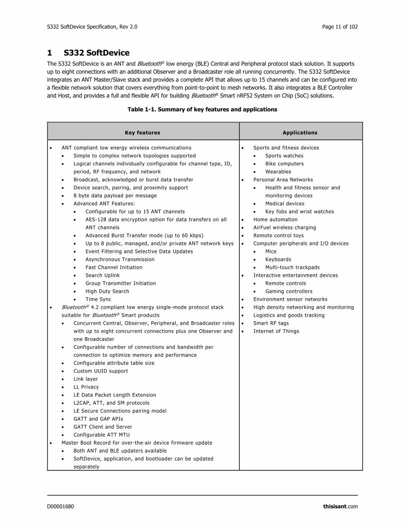
1 S332 SoftDevice
The S332 SoftDevice is an ANT and Bluetooth® low energy (BLE) Central and Peripheral protocol stack solution. It supports
up to eight connections with an additional Observer and a Broadcaster role all running concurrently. The S332 SoftDevice
integrates an ANT Master/Slave stack and provides a complete API that allows up to 15 channels and can be configured into
a flexible network solution that covers everything from point-to-point to mesh networks. It also integrates a BLE Controller
and Host, and provides a full and flexible API for building Bluetooth® Smart nRF52 System on Chip (SoC) solutions.
Table 1-1. Summary of key features and applications
Key features Applications
ANT compliant low energy wireless communications
Simple to complex network topologies supported
Logical channels individually configurable for channel type, ID,
period, RF frequency, and network
Broadcast, acknowledged or burst data transfer
Device search, pairing, and proximity support
8 byte data payload per message
Advanced ANT Features:
Configurable for up to 15 ANT channels
AES-128 data encryption option for data transfers on all
ANT channels
Advanced Burst Transfer mode (up to 60 kbps)
Up to 8 public, managed, and/or private ANT network keys
Event Filtering and Selective Data Updates
Asynchronous Transmission
Fast Channel Initiation
Search Uplink
Group Transmitter Initiation
High Duty Search
Time Sync
Bluetooth® 4.2 compliant low energy single-mode protocol stack
suitable for Bluetooth® Smart products
Concurrent Central, Observer, Peripheral, and Broadcaster roles
with up to eight concurrent connections plus one Observer and
one Broadcaster
Configurable number of connections and bandwidth per
connection to optimize memory and performance
Configurable attribute table size
Custom UUID support
Link layer
LL Privacy
LE Data Packet Length Extension
L2CAP, ATT, and SM protocols
LE Secure Connections pairing model
GATT and GAP APIs
GATT Client and Server
Configurable ATT MTU
Master Boot Record for over-the-air device firmware update
Both ANT and BLE updaters available
SoftDevice, application, and bootloader can be updated
separately
Sports and fitness devices
Sports watches
Bike computers
Wearables
Personal Area Networks
Health and fitness sensor and
monitoring devices
Medical devices
Key fobs and wrist watches
Home automation
AirFuel wireless charging
Remote control toys
Computer peripherals and I/O devices
Mice
Keyboards
Multi-touch trackpads
Interactive entertainment devices
Remote controls
Gaming controllers
Environment sensor networks
High density networking and monitoring
Logistics and goods tracking
Smart RF tags
Internet of Things
Page 12 of 102 S332 SoftDevice Specification, Rev 2.0
D00001680 thisisant.com
Key features Applications
Memory isolation between the application and the protocol stack for
robustness and security
Thread-safe supervisor-call based API
Asynchronous, event-driven behaviour
No RTOS dependency
Any RTOS can be used
No link-time dependencies
Standard ARM® Cortex®-M4 project configuration for
application development
Support for concurrent and non-concurrent multiprotocol operation
Concurrent with the ANT stack using the Radio Timeslot API
Concurrent with the Bluetooth® stack using Radio Timeslot API
Alternate protocol stack in application space
Support for control of external Power Amplifiers and Low Noise
Amplifiers
S332 SoftDevice Specification, Rev 2.0 Page 13 of 102
D00001680 thisisant.com
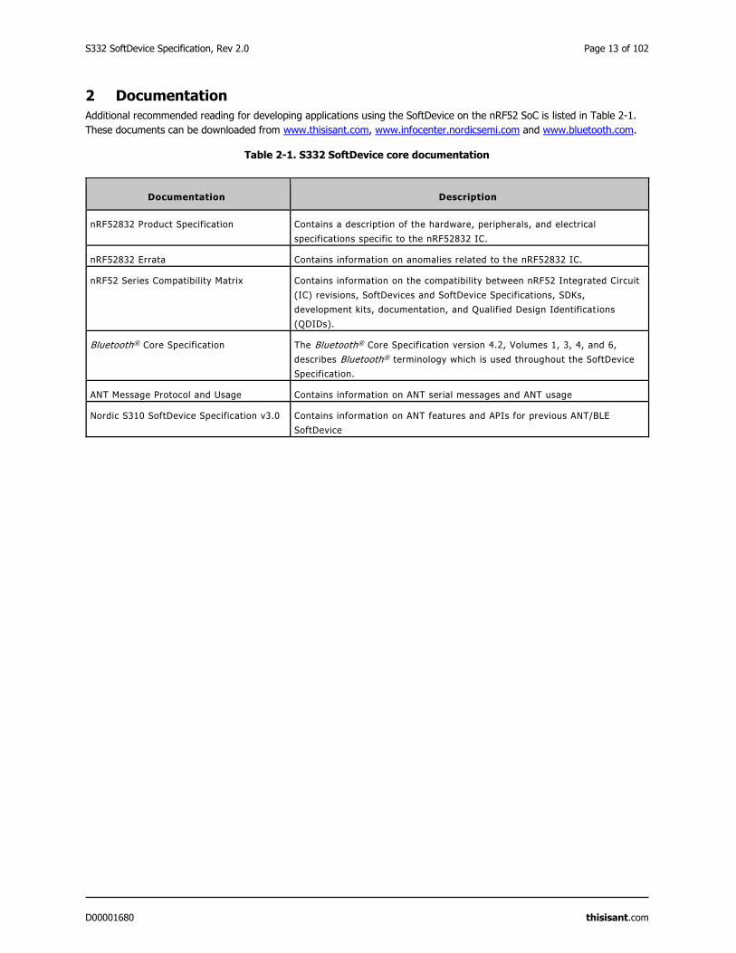
2 Documentation
Additional recommended reading for developing applications using the SoftDevice on the nRF52 SoC is listed in Table 2-1.
These documents can be downloaded from www.thisisant.com, www.infocenter.nordicsemi.com and www.bluetooth.com.
Table 2-1. S332 SoftDevice core documentation
Documentation Description
nRF52832 Product Specification Contains a description of the hardware, peripherals, and electrical
specifications specific to the nRF52832 IC.
nRF52832 Errata Contains information on anomalies related to the nRF52832 IC.
nRF52 Series Compatibility Matrix Contains information on the compatibility between nRF52 Integrated Circuit
(IC) revisions, SoftDevices and SoftDevice Specifications, SDKs,
development kits, documentation, and Qualified Design Identificat ions
(QDIDs).
Bluetooth® Core Specification The Bluetooth® Core Specification version 4.2, Volumes 1, 3, 4, and 6,
describes Bluetooth® terminology which is used throughout the SoftDevice
Specification.
ANT Message Protocol and Usage Contains information on ANT serial messages and ANT usage
Nordic S310 SoftDevice Specification v3.0 Contains information on ANT features and APIs for previous ANT/BLE
SoftDevice
Page 14 of 102 S332 SoftDevice Specification, Rev 2.0
D00001680 thisisant.com
3 Product Overview
The S332 SoftDevice is a precompiled and linked binary image implementing an ANT protocol stack and a Bluetooth® 4.2
low energy protocol stack for the nRF52 Series of SoCs.
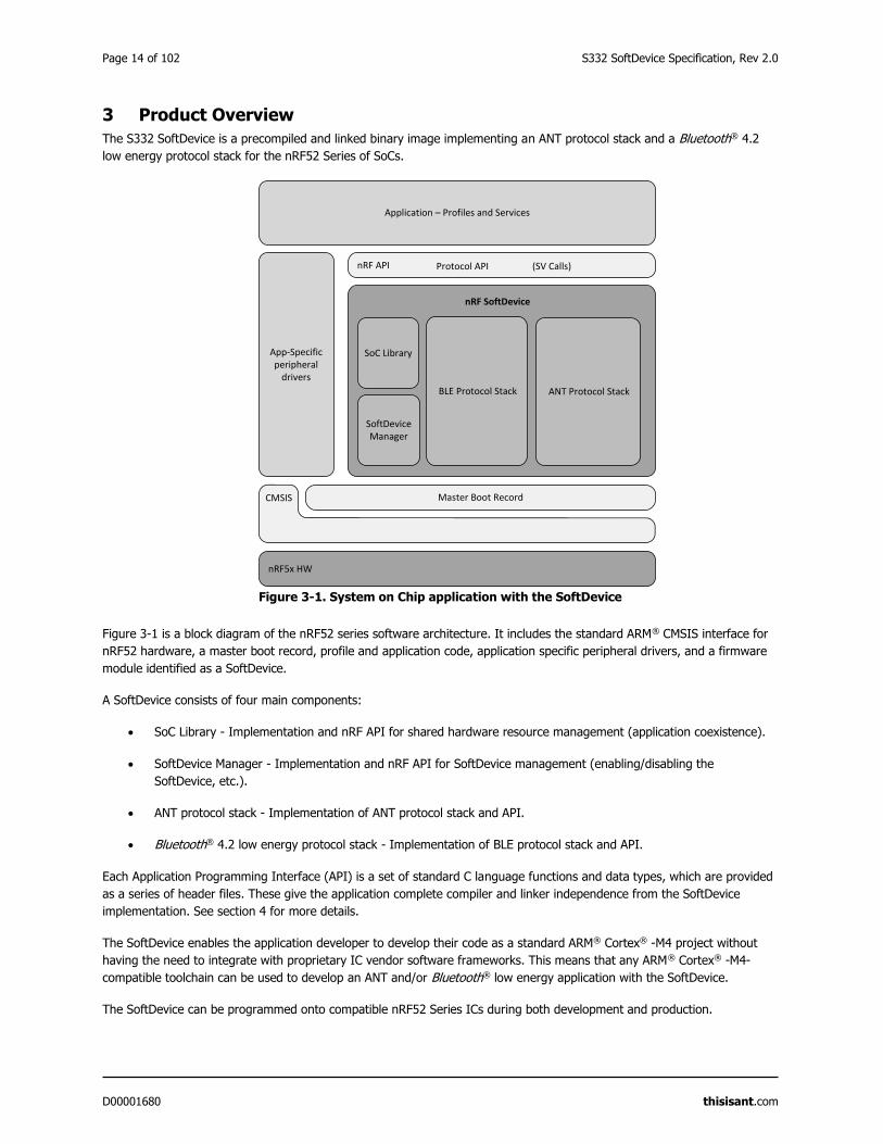
Figure 3-1. System on Chip application with the SoftDevice
Figure 3-1 is a block diagram of the nRF52 series software architecture. It includes the standard ARM® CMSIS interface for
nRF52 hardware, a master boot record, profile and application code, application specific peripheral drivers, and a firmware
module identified as a SoftDevice.
A SoftDevice consists of four main components:
SoC Library - Implementation and nRF API for shared hardware resource management (application coexistence).
SoftDevice Manager - Implementation and nRF API for SoftDevice management (enabling/disabling the
SoftDevice, etc.).
ANT protocol stack - Implementation of ANT protocol stack and API.
Bluetooth® 4.2 low energy protocol stack - Implementation of BLE protocol stack and API.
Each Application Programming Interface (API) is a set of standard C language functions and data types, which are provided
as a series of header files. These give the application complete compiler and linker independence from the SoftDevice
implementation. See section 4 for more details.
The SoftDevice enables the application developer to develop their code as a standard ARM® Cortex® -M4 project without
having the need to integrate with proprietary IC vendor software frameworks. This means that any ARM® Cortex® -M4-
compatible toolchain can be used to develop an ANT and/or Bluetooth® low energy application with the SoftDevice.
The SoftDevice can be programmed onto compatible nRF52 Series ICs during both development and production.
nRF API
Application – Profiles and Services
App-Specific peripheral
drivers
nRF5x HW
nRF SoftDevice
ANT Protocol Stack
SoftDevice Manager
SoC Library
Protocol API (SV Calls)
Master Boot RecordCMSIS
BLE Protocol Stack
S332 SoftDevice Specification, Rev 2.0 Page 15 of 102
D00001680 thisisant.com
4 Application Programming Interface (API)
The SoftDevice Application Programming Interface (API) is available to applications as a C programming language interface
based on SuperVisor Calls (SVC) and defined in a set of header files.
In addition to a Protocol API enabling wireless applications, there is an nRF API that exposes the functionality of both the
SoftDevice Manager and the SoC Library.
Important: When the SoftDevice is disabled, only a subset of the SoftDevice API is available to the application (see S332
SoftDevice v2.0.1 API). For more information about enabling and disabling the SoftDevice, see section 5.1.
SVCs are software triggered interrupts conforming to a procedure call standard for parameter passing and return values.
Each SoftDevice API call triggers an SVC interrupt. The SoftDevice SVC interrupt handler locates the correct SoftDevice
function, allowing applications to compile without any API function address information at compile time. This removes the
necessity for the application to link to the SoftDevice. The header files contain all information required for the application to
invoke the API functions with standard programming language prototypes. This SVC interface makes SoftDevice API calls
thread-safe; they can be invoked from the application's different priority levels without additional synchronization
mechanisms.
Important: SoftDevice API functions can only be called from a lower interrupt priority level (higher numerical value for the
priority level) than the SVC priority. For more information, see section 17.2.
4.1 Events – SoftDevice to application
Software triggered interrupts in a reserved IRQ are used to signal events from the SoftDevice to the application. The
application is then responsible for handling the interrupt and for invoking the relevant SoftDevice functions to obtain the
event data.
For details on how to implement the handling of these events, see the nRF5 Software Development Kit (nRF5 SDK)
documentation available at www.nordicsemi.com.
4.2 Error handling
All SoftDevice API functions return a 32-bit error code. The application must check this error code to confirm whether a
SoftDevice API function call was successful.
Unrecoverable failures (faults) detected by the SoftDevice will be reported to the application by a registered, fault handling
callback function. A pointer to the fault handler must be provided by the application upon SoftDevice initialization. The fault
handler is then used to notify of unrecoverable errors and the type of error is indicated as a parameter through the fault
handler.
The following types of faults can be reported to the application through the fault handler:
SoftDevice assertions.
Attempts by the application to perform illegal memory accesses, either against SoftDevice memory protection rules
or to protected peripheral configuration registers at runtime.
The fault handler callback is invoked by the SoftDevice in HardFault context, with all interrupts disabled.
Page 16 of 102 S332 SoftDevice Specification, Rev 2.0
D00001680 thisisant.com
5 SoftDevice Manager
The SoftDevice Manager (SDM) API allows the application to control the SoftDevice state and configure the behaviour of
certain SoftDevice core functionality.
When enabling the SoftDevice, the SDM configures the following:
The low frequency clock (LFCLK) source (section 5.2).
The interrupt management (section5.1).
The embedded protocol stack.
In addition, it enables the SoftDevice RAM and peripheral protection. See section 5.4.
Detailed documentation of the SDM API is made available with the Software Development Kits (SDK).
5.1 SoftDevice enable and disable
When the SoftDevice is not enabled, the Protocol API and parts of the SoC Library API are not available to the application.
When the SoftDevice is not enabled, most of the SoCs resources are available to the application. However, the following
restrictions apply:
SVC numbers 0x10 to 0xFF are reserved.
SoftDevice program (flash) memory is reserved.
A few bytes of RAM are reserved (section 15.1)
Once the SoftDevice has been enabled, more restrictions apply:
Some RAM will be reserved (section 5.4)
Some peripherals will be reserved (section 7.1).
Some of the peripherals that are reserved will have a SoC Library interface.
Interrupts from the reserved SoftDevice peripherals will not be forwarded to the application (section 17.1.1).
The reserved peripherals are reset upon SoftDevice disable.
nrf_nvic_ functions must be used instead of CMSIS NVIC_ functions for safe use of the SoftDevice.
SoftDevice activity in high priority levels may interrupt the application, increasing the maximum interrupt latency
(section 17).
5.1.1 ANT License Key
The S332 SoftDevice requires a license key in order to operate. An evaluation key is included in the SoftDevice which will
enable the full stack and is to be used for NON-COMMERCIAL USE ONLY. Further information about the license key and/or
obtaining a commercial license key can be found at: www.thisisant.com/developer/ant/licensing.
License validation may cause the enable time of the SoftDevice to extend by up to 100 ms in some configurations.
5.2 Clock source
The SoftDevice can use one of two available low frequency clock sources: the internal RC Oscillator, or an external Crystal
Oscillator.
S332 SoftDevice Specification, Rev 2.0 Page 17 of 102
D00001680 thisisant.com
The application must provide the selected clock source and some clock source characteristics, such as accuracy, when it
enables the SoftDevice. The SoftDevice Manager is responsible for configuring the low frequency clock source and for
keeping it calibrated, when the RC oscillator is the selected clock source.
If the SoftDevice is configured with the internal RC oscillator clock option, clock calibration is required periodically and when
a temperature change of more than 0.5°C has occurred, to adjust the RC oscillator frequency. See the nRF52832 Product
Specification for more information. The SoftDevice will perform this function automatically. The application may choose how
often the SoftDevice will make a measurement to detect temperature change based on how frequently significant
temperature changes are expected to occur in the intended environment of the end product. A temperature polling interval
of 4 seconds and a forced clock calibration every second interval (8 seconds) is recommended (.ctiv=32, .temp_ctiv=2).
5.3 Power management
The SoftDevice implements a simple to use SoftDevice Power API for optimized power management.
The application shall use this API when the SoftDevice is enabled to ensure correct function. When the SoftDevice is
disabled, the application must use the hardware abstraction (CMSIS) interfaces for power management.
When waiting for application events using the Power API, the CPU goes to an IDLE state whenever the SoftDevice is not
using the CPU. Interrupts handled directly by the SoftDevice do not wake the application. Application interrupts will wake
the application as expected. When going to system OFF, the Power API ensures the SoftDevice services are stopped before
powering down.
5.4 Memory isolation and runtime protection
The SoftDevice data memory and peripherals can be sandboxed and runtime protected to prevent the application from
interfering with the SoftDevice execution, ensuring robust and predictable performance.
Sandboxing1 and runtime protection can allow memory access violations to be detected at development time. This ensures
that developed applications will not inadvertently interfere with the correct functioning of the SoftDevice.
Sandboxing is enabled by default when the SoftDevice is enabled and disabled when the SoftDevice is disabled. When
enabled, SoftDevice RAM and peripheral registers are protected against write access by the application. The application will
have read access to SoftDevice RAM and peripheral registers.
The flash memory is divided into two regions at compile time. The SoftDevice Flash Region is located between addresses
0x00000000 and APP_CODE_BASE - 1 and is occupied by the SoftDevice. The Application Flash Region is located between
the addresses APP_CODE_BASE and the last valid address in the flash memory and is available to the application.
The RAM is also split into two regions, which are defined at runtime, when the SoftDevice is enabled. The SoftDevice RAM
Region is located between the addresses 0x20000000 and APP_RAM_BASE - 1 and is used by the SoftDevice. The
Application RAM Region is located between the addresses APP_RAM_BASE and the top of RAM and is available to the
application.
1 A sandbox is a set of memory access restrictions imposed on the application
Page 18 of 102 S332 SoftDevice Specification, Rev 2.0
D00001680 thisisant.com
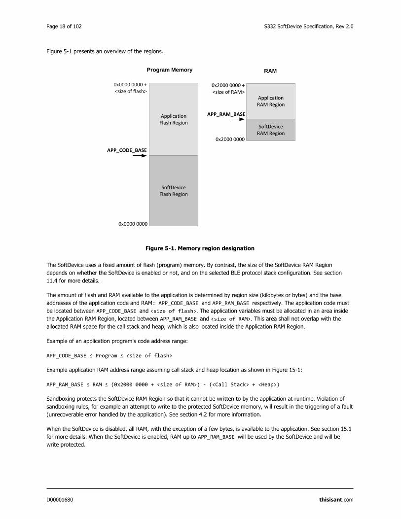
Figure 5-1 presents an overview of the regions.
Figure 5-1. Memory region designation
The SoftDevice uses a fixed amount of flash (program) memory. By contrast, the size of the SoftDevice RAM Region
depends on whether the SoftDevice is enabled or not, and on the selected BLE protocol stack configuration. See section
11.4 for more details.
The amount of flash and RAM available to the application is determined by region size (kilobytes or bytes) and the base
addresses of the application code and RAM: APP_CODE_BASE and APP_RAM_BASE respectively. The application code must
be located between APP_CODE_BASE and <size of flash>. The application variables must be allocated in an area inside
the Application RAM Region, located between APP_RAM_BASE and <size of RAM>. This area shall not overlap with the
allocated RAM space for the call stack and heap, which is also located inside the Application RAM Region.
Example of an application program's code address range:
APP_CODE_BASE ≤ Program ≤ <size of flash>
Example application RAM address range assuming call stack and heap location as shown in Figure 15-1:
APP_RAM_BASE ≤ RAM ≤ (0x2000 0000 + <size of RAM>) - (<Call Stack> + <Heap>)
Sandboxing protects the SoftDevice RAM Region so that it cannot be written to by the application at runtime. Violation of
sandboxing rules, for example an attempt to write to the protected SoftDevice memory, will result in the triggering of a fault
(unrecoverable error handled by the application). See section 4.2 for more information.
When the SoftDevice is disabled, all RAM, with the exception of a few bytes, is available to the application. See section 15.1
for more details. When the SoftDevice is enabled, RAM up to APP_RAM_BASE will be used by the SoftDevice and will be
write protected.
SoftDeviceFlash Region
Application Flash Region
APP_CODE_BASE
0x0000 0000
0x0000 0000 +<size of flash>
Program Memory RAM
SoftDeviceRAM Region
ApplicationRAM Region
APP_RAM_BASE
0x2000 0000
0x2000 0000 +<size of RAM>
S332 SoftDevice Specification, Rev 2.0 Page 19 of 102
D00001680 thisisant.com
The typical location of the call stack for an application using the SoftDevice is in the upper part of the Application RAM
Region, so the application can place its variables from the end of the SoftDevice RAM Region (APP_RAM_BASE) to the
beginning of the call stack space.
Important:
The location of the call stack is communicated to the SoftDevice through the contents of the Main Stack Pointer
(MSP) register.
Do not change the value of MSP dynamically (i.e. never set the MSP register directly).
The RAM located in the SoftDevice RAM Region will be overwritten once the SoftDevice is enabled.
The SoftDevice RAM Region will be not be cleared or restored to default values after disabling the SoftDevice, so
the application must treat the contents of the region as uninitialized memory.
Page 20 of 102 S332 SoftDevice Specification, Rev 2.0
D00001680 thisisant.com
6 System on Chip (SoC) Library
The coexistence of Application and SoftDevice with safe sharing of common System on Chip (SoC) resources is ensured by
the SoC Library.
The features described in Table 6-1 are implemented by the SoC Library and can be used for accessing the shared hardware
resources.
Table 6-1. System on Chip features
Feature Description
Mutex The SoftDevice implements atomic mutex acquire and release operations
that are safe for the application to use. Use this mutex to avoid disabling
global interrupts in the application, because disabling global interrupts
will interfere with the SoftDevice and may lead to dropped packets or lost
connections.
NVIC Wrapper functions for the CMSIS NVIC functions provided by ARM ®.
Important: To ensure reliable usage of the SoftDevice you must use the
wrapper functions when the SoftDevice is enabled.
Rand Provides random numbers from the hardware random number generator.
Power Access to power block configuration while the SoftDevice is enabled:
Access to RESETREAS register
Set power modes
Configure power fail comparator
Control RAM block power
Use general purpose retention register
Configure DC/DC converter state:
DISABLED
ENABLED
Clock Access to clock block configuration while the SoftDevice is enabled.
Allows the HFCLK Crystal Oscillator source to be requested by the
application.
Wait for event Simple power management call for the application to use to enter a sleep
or idle state and wait for an application event.
PPI Configuration interface for PPI channels and groups reserved for an
application.
Radio Timeslot API Schedule other radio protocol activity, or periods of radio inactivity. See
section 9.2.
Radio Notification Configure Radio Notification signals on ACTIVE and/or nACTIVE. See
section 12.1.
Block Encrypt (ECB) Safe use of 128-bit AES encrypt HW accelerator.
Event API Fetch asynchronous events generated by the SoC Library.
Flash memory API Application access to flash write, erase, and protect. Can be safely used
during all protocol stack states. See section 8.
Temperature Application access to the temperature sensor.
S332 SoftDevice Specification, Rev 2.0 Page 21 of 102
D00001680 thisisant.com
7 System on Chip resource requirements
This section describes how the SoftDevice, including the Master Boot Record (MBR), uses the System on Chip (SoC)
resources. The SoftDevice requirements are shown for both when the SoftDevice is enabled and disabled.
The SoftDevice and MBR (section 13) are designed to be installed on the nRF SoC in the lower part of the code memory
space. After a reset, the MBR will use some RAM to store state information. When the SoftDevice is enabled, it uses
resources on the SoC including RAM and hardware peripherals like the radio. For the amount of RAM required by the
SoftDevice see section 15.
7.1 Hardware peripherals
Hardware access types are used to indicate the availability of hardware peripherals to the application. The availability varies
per hardware peripheral and depends on whether the SoftDevice is enabled or disabled.
Table 7-1. Hardware access type definitions
Access type Description
Restricted Used by the SoftDevice and outside the application sandbox.
The application has limited access through the SoftDevice API.
Blocked Used by the SoftDevice and outside the application sandbox.
The application has no access.
Open Not used by the SoftDevice.
The application has full access.
Table 7-2. Peripheral protection and usage by SoftDevice
ID Base address Instance Access
SoftDevice enabled
Access
SoftDevice disabled
0 0x40000000 CLOCK Restricted Open
0 0x40000000 POWER Restricted Open
0 0x40000000 BPROT Restricted Open
1 0x40001000 RADIO Blocked2 Open
2 0x40002000 UART0 / UARTE0 Open Open
3 0x40003000 TWIM0 / TWIS0 /
SPIM0 / SPIS0 / SPI0
/TWI0
Open Open
2 Available to the application through the Radio Timeslot API, see section 9.2.
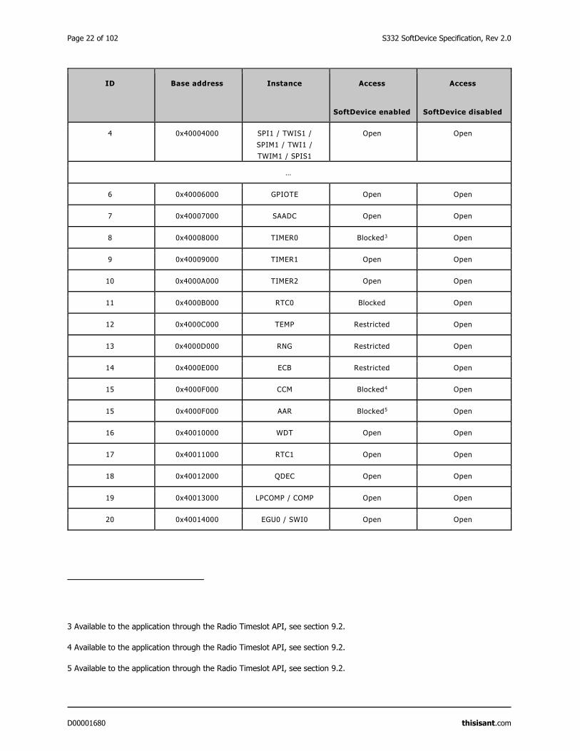
Page 22 of 102 S332 SoftDevice Specification, Rev 2.0
D00001680 thisisant.com
ID Base address Instance Access
SoftDevice enabled
Access
SoftDevice disabled
4 0x40004000 SPI1 / TWIS1 /
SPIM1 / TWI1 /
TWIM1 / SPIS1
Open Open
…
6 0x40006000 GPIOTE Open Open
7 0x40007000 SAADC Open Open
8 0x40008000 TIMER0 Blocked3 Open
9 0x40009000 TIMER1 Open Open
10 0x4000A000 TIMER2 Open Open
11 0x4000B000 RTC0 Blocked Open
12 0x4000C000 TEMP Restricted Open
13 0x4000D000 RNG Restricted Open
14 0x4000E000 ECB Restricted Open
15 0x4000F000 CCM Blocked4 Open
15 0x4000F000 AAR Blocked5 Open
16 0x40010000 WDT Open Open
17 0x40011000 RTC1 Open Open
18 0x40012000 QDEC Open Open
19 0x40013000 LPCOMP / COMP Open Open
20 0x40014000 EGU0 / SWI0 Open Open
3 Available to the application through the Radio Timeslot API, see section 9.2.
4 Available to the application through the Radio Timeslot API, see section 9.2.
5 Available to the application through the Radio Timeslot API, see section 9.2.
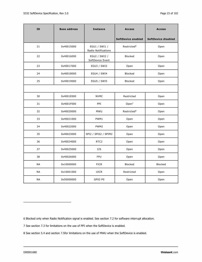
S332 SoftDevice Specification, Rev 2.0 Page 23 of 102
D00001680 thisisant.com
ID Base address Instance Access
SoftDevice enabled
Access
SoftDevice disabled
21 0x40015000 EGU1 / SWI1 /
Radio Notifications
Restricted6 Open
22 0x40016000 EGU2 / SWI2 /
SoftDevice Event
Blocked Open
23 0x40017000 EGU3 / SWI3 Open Open
24 0x40018000 EGU4 / SWI4 Blocked Open
25 0x40019000 EGU5 / SWI5 Blocked Open
…
30 0x4001E000 NVMC Restricted Open
31 0x4001F000 PPI Open7 Open
32 0x40020000 MWU Restricted8 Open
33 0x40021000 PWM1 Open Open
34 0x40022000 PWM2 Open Open
35 0x40023000 SPI2 / SPIS2 / SPIM2 Open Open
36 0x40024000 RTC2 Open Open
37 0x40025000 I2S Open Open
38 0x40026000 FPU Open Open
NA 0x10000000 FICR Blocked Blocked
NA 0x10001000 UICR Restricted Open
NA 0x50000000 GPIO P0 Open Open
6 Blocked only when Radio Notification signal is enabled. See section 7.2 for software interrupt allocation.
7 See section 7.3 for limitations on the use of PPI when the SoftDevice is enabled.
8 See section 5.4 and section 7.5for limitations on the use of MWU when the SoftDevice is enabled.
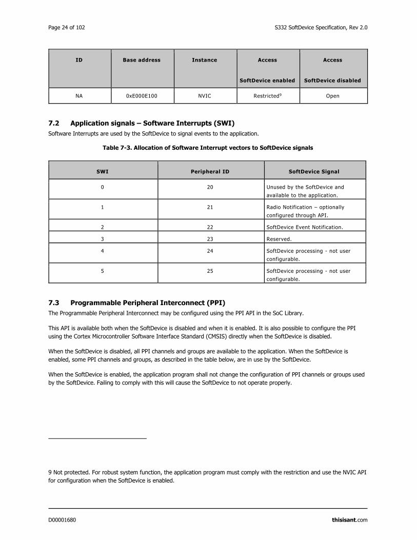
Page 24 of 102 S332 SoftDevice Specification, Rev 2.0
D00001680 thisisant.com
ID Base address Instance Access
SoftDevice enabled
Access
SoftDevice disabled
NA 0xE000E100 NVIC Restricted9 Open
7.2 Application signals – Software Interrupts (SWI)
Software Interrupts are used by the SoftDevice to signal events to the application.
Table 7-3. Allocation of Software Interrupt vectors to SoftDevice signals
SWI Peripheral ID SoftDevice Signal
0 20 Unused by the SoftDevice and
available to the application.
1 21 Radio Notification – optionally
configured through API.
2 22 SoftDevice Event Notification.
3 23 Reserved.
4 24 SoftDevice processing - not user
configurable.
5 25 SoftDevice processing - not user
configurable.
7.3 Programmable Peripheral Interconnect (PPI)
The Programmable Peripheral Interconnect may be configured using the PPI API in the SoC Library.
This API is available both when the SoftDevice is disabled and when it is enabled. It is also possible to configure the PPI
using the Cortex Microcontroller Software Interface Standard (CMSIS) directly when the SoftDevice is disabled.
When the SoftDevice is disabled, all PPI channels and groups are available to the application. When the SoftDevice is
enabled, some PPI channels and groups, as described in the table below, are in use by the SoftDevice.
When the SoftDevice is enabled, the application program shall not change the configuration of PPI channels or groups used
by the SoftDevice. Failing to comply with this will cause the SoftDevice to not operate properly.
9 Not protected. For robust system function, the application program must comply with the restriction and use the NVIC API
for configuration when the SoftDevice is enabled.
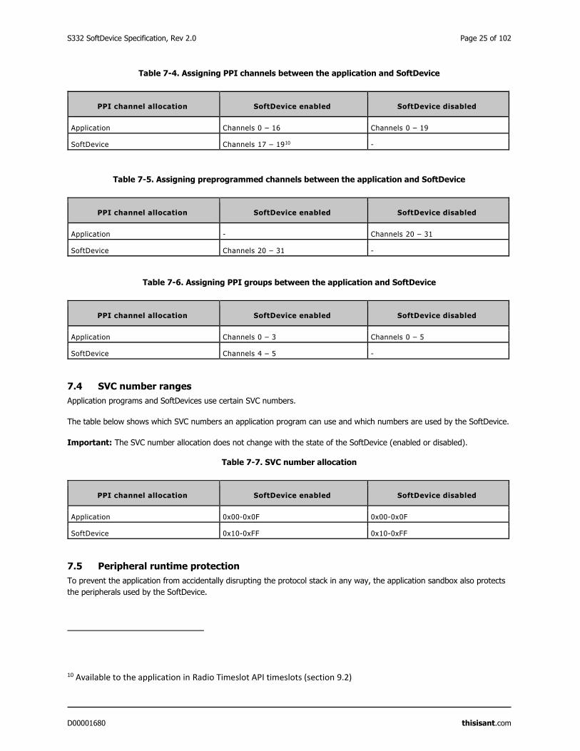
S332 SoftDevice Specification, Rev 2.0 Page 25 of 102
D00001680 thisisant.com
Table 7-4. Assigning PPI channels between the application and SoftDevice
PPI channel allocation SoftDevice enabled SoftDevice disabled
Application Channels 0 – 16 Channels 0 – 19
SoftDevice Channels 17 – 1910 -
Table 7-5. Assigning preprogrammed channels between the application and SoftDevice
PPI channel allocation SoftDevice enabled SoftDevice disabled
Application - Channels 20 – 31
SoftDevice Channels 20 – 31 -
Table 7-6. Assigning PPI groups between the application and SoftDevice
PPI channel allocation SoftDevice enabled SoftDevice disabled
Application Channels 0 – 3 Channels 0 – 5
SoftDevice Channels 4 – 5 -
7.4 SVC number ranges
Application programs and SoftDevices use certain SVC numbers.
The table below shows which SVC numbers an application program can use and which numbers are used by the SoftDevice.
Important: The SVC number allocation does not change with the state of the SoftDevice (enabled or disabled).
Table 7-7. SVC number allocation
PPI channel allocation SoftDevice enabled SoftDevice disabled
Application 0x00-0x0F 0x00-0x0F
SoftDevice 0x10-0xFF 0x10-0xFF
7.5 Peripheral runtime protection
To prevent the application from accidentally disrupting the protocol stack in any way, the application sandbox also protects
the peripherals used by the SoftDevice.
10 Available to the application in Radio Timeslot API timeslots (section 9.2)
Page 26 of 102 S332 SoftDevice Specification, Rev 2.0
D00001680 thisisant.com
Protected peripheral registers are readable by the application. An attempt to perform a write to a protected peripheral
register will result in a Hard Fault. See section 4.2 for more details on faults due to prohibited memory access. Note that the
peripherals are only protected when the SoftDevice is enabled; otherwise they are available to the application. See Table
7-2 for an overview of the peripherals with access restrictions due to the SoftDevice.
7.6 External and miscellaneous requirements
For correct operation of the SoftDevice, it is a requirement that the 16MHz crystal oscillator (16MHz XOSC) startup time is
less than 1.5ms.
The external clock crystal and other related components must be chosen accordingly. Data for the crystal oscillator input
can be found in the product specification for the SoC (nRF52832 Product Specification).
When the SoftDevice is enabled the SEVONPEND flag in the SCR register of the CPU shall only be changed from main or low
interrupt level (priority not higher than 4), otherwise the behaviour of the SoftDevice is undefined and the SoftDevice might
malfunction.
S332 SoftDevice Specification, Rev 2.0 Page 27 of 102
D00001680 thisisant.com
8 Flash memory API
The System on Chip (SoC) Flash Memory API provides the application with flash write, flash erase, and flash protect support
through the SoftDevice. Asynchronous flash memory operations can be safely performed during active ANT and BLE
connections using the Flash Memory API of the SoC Library.
The flash memory accesses are scheduled to not disturb radio events. See section 16.8 for details. If the protocol radio
events are in a critical state, flash memory accesses may be delayed for a long period resulting in a timeout event. In this
case, NRF_EVT_FLASH_OPERATION_ERROR will be returned in the application event handler. If this happens, retry the flash
memory operation.
Important: Flash page (4096 bytes) erase can take up to 90ms and a 4 byte flash write can take up to 338μs. A flash
write must be made in chunks smaller than or equal to the flash page size. Make flash writes in the smallest chunks possible
to increase the probability of success, and reduce the chances of affecting ANT or BLE performance.
8.1 Using flash with ANT activity
The SoC Library API can safely be used during ANT radio activities to perform asynchronous flash memory operations.
The flash memory access is scheduled between the protocol radio events. For certain memory access operations, the time
required may be longer than the time between radio events. In this case, the radio event may be skipped or the flash
memory access may be delayed. If the flash operation requires more time than allowed to run concurrently with certain ANT
activities, the flash memory access may fail and generate a timeout event: NRF_EVT_FLASH_OPERATION_ERROR. In this
case, retry the flash operation.
Table 8-1. Behaviour with ANT traffic and concurrent flash write/erase
ANT Activity Flash Write
ANT Rx Scanning Channel
ANT Rx Search/Background Search
ANT Rx High Duty Search
ANT Tx/Rx Broadcast Messaging
ANT Tx/Rx Acknowledged Messaging
Supports full flash write size (256 words).
Flash timeout event may be generated if critical ANT radio
activities need to occur.
ANT transmit/receive performance may be impacted if continuous
flash write operations are requested.
ANT Tx/Rx Burst Transfer
Maximum recommended flash write size is 64 words. Larger flash
writes may result in flash timeout events or burst transfer
failures.
Continuous flash write activity may result in burst transfers
taking up to 2-3 times longer to complete.
ANT Activity Flash Erase
ANT Rx Scanning Channel
ANT Rx Search
ANT Tx/Rx Broadcast Messaging
ANT Tx/Rx Acknowledged Messaging
Supports flash erase attempts.
Flash timeout event may be generated if critical ANT radio
activities need to occur.
ANT transmit/receive performance may be impacted if continuous
flash erase operations are requested.
ANT Tx/Rx Burst Transfer
ANT Rx High Duty Search
Flash erase not supported. Flash erase attempts may result in
flash timeout event or burst transfer failures.
8.2 Using flash with BLE activity
During BLE activity, examples of critical phases of radio events include: connection setup, connection update, disconnection,
and impending supervision timeout.
Page 28 of 102 S332 SoftDevice Specification, Rev 2.0
D00001680 thisisant.com
The probability of successfully accessing the flash memory decreases with increasing scheduler activity (i.e. radio activity
and timeslot activity). With long connection intervals there will be a higher probability of accessing flash memory
successfully. Use the guidelines in Table 8-2 to improve the probability of flash operation success.
Table 8-2. Behaviour with BLE traffic and concurrent flash write/erase
BLE activity Flash write/erase (flash write size is assumed to be 4 bytes)
High duty cycle directed advertising Does not allow flash operation while advertising is active
(maximum 1.28s). In this case, retrying flash operation
will only succeed after the advertising activity has
finished.
All possible BLE roles running concurrently (connections as
a Central, Peripheral, Advertiser, and Scanner).
Low to medium probability of flash operation success
Probability of success increases with:
Lower bandwidth configurations.
Increase in connection interval and advertiser
interval.
Decrease in scan window.
Increase in scan interval.
8 high bandwidth connections as a Central
1 high bandwidth connection as a Peripheral
All active connections fulfill the following criteria:
Supervision timeout > 6 x connection interval
Connection interval ≥ 150ms
All central connections have the same connection
interval
High probability of flash write success.
Medium probability of flash erase success. (High
probability if the connection interval is > 240ms)
8 high bandwidth connections as a Central
All active connections fulfill the following criteria:
Supervision timeout > 6 x connection interval
Connection interval ≥ 150ms
All connections have the same connection interval
High probability of flash operation success.
8 low bandwidth connections as a Central
All active connections fulfill the following criteria:
Supervision timeout > 6 x connection interval
Connection interval ≥ 110ms
All connections have the same connection interval
High probability of flash operation success.
1 connection as a Peripheral
All active connections fulfill the following criteria:
Supervision timeout > 6 x connection interval
Connection interval ≥ 25ms
High probability of flash operation success.
Connectable undirected advertising
Nonconnectable advertising
Scannable advertising
Connectable low duty cycle directed advertising
High probability of flash operation success.
No BLE activity Flash operation will always succeed.
S332 SoftDevice Specification, Rev 2.0 Page 29 of 102
D00001680 thisisant.com
9 Multiprotocol support
Multiprotocol support allows a developer to implement a custom 2.4 GHz proprietary protocol in the application; both while
the SoftDevice is not in use (non-concurrent), and while the SoftDevice protocol stack is in use (concurrent). For concurrent
multiprotocol implementations, the Radio Timeslot API allows the application protocol to safely schedule radio usage
between ANT and/or BLE events.
9.1 Non-concurrent multiprotocol implementation
For non-concurrent operation a proprietary 2.4 GHz protocol can be implemented in the application program area and can
access all hardware resources when the SoftDevice is disabled. The SoftDevice may be disabled and enabled without
resetting the application in order to switch between a proprietary protocol stack and ANT/Bluetooth® communication.
9.2 Concurrent multiprotocol implementation using the Radio Timeslot API
The Radio Timeslot API allows the nRF52 device to be part of a network using the SoftDevice protocol stack and an
alternative network of wireless devices using a custom protocol at the same time.
The Radio Timeslot (or, simply, Timeslot) feature gives the application access to the radio and other restricted peripherals
during defined time intervals, denoted as timeslots. The Timeslot feature achieves this by cooperatively scheduling the
application's use of these peripherals with those of the SoftDevice. Using this feature, the application can run other radio
protocols (third party custom or proprietary protocols running from application space) concurrently with the internal protocol
stack(s) of the SoftDevice. It can also be used to suppress SoftDevice radio activity and to reserve guaranteed time for
application activities with hard timing requirements, which cannot be met by using the SoC Radio Notifications.
The Timeslot feature is part of the SoC Library. The feature works by having the SoftDevice time-multiplex access to
peripherals between the application and itself. Through the SoC Library API, the application can open a Timeslot session
and request timeslots. When a Timeslot request is granted, the application has exclusive and real-time access to the
normally blocked RADIO, TIMER0, CCM, and AAR peripherals and can use these freely for the duration (length) of the
timeslot, see Table 7-1 and Table 7-2.
9.2.1 Request types
There are two types of Radio Timeslot requests, earliest possible Timeslot requests and normal Timeslot requests.
Timeslots may be requested as earliest possible, in which case the timeslot occurs at the first available opportunity. In the
request, the application can limit how far into the future the timeslot may be placed.
Important: The first request in a session must always be earliest possible to create the timing reference point for later
timeslots.
Timeslots may also be requested at a given time (normal). In this case, the application specifies in the request when the
timeslot should start and the time is measured from the start of the previous timeslot.
The application may also request an extension to an ongoing timeslot. Extension requests may be repeated, prolonging the
timeslot even further.
Timeslots requested as earliest possible are useful for single timeslots and for non-periodic or non-timed activity. Timeslots
requested at a given time relative to the previous timeslot are useful for periodic and timed activities; for example, a
periodic proprietary radio protocol. Timeslot extension may be used to secure as much continuous radio time as possible for
the application; for example, running an ‘always on’ radio listener.
9.2.2 Request priorities
Radio Timeslots can be requested at either high or normal priority, indicating how important it is for the application to
access the specified peripherals. A Timeslot request can only be blocked or cancelled due to an overlapping SoftDevice
activity that has a higher scheduling priority.
Page 30 of 102 S332 SoftDevice Specification, Rev 2.0
D00001680 thisisant.com
9.2.3 Timeslot length
A Radio Timeslot is requested for a given length of time. Ongoing timeslots have the possibility to be extended.
The length of the timeslot is specified by the application in the Timeslot request and ranges from 100μs to 100ms. A
timeslot may be extended multiple times, as long as its duration does not extend beyond the time limits set by other
SoftDevice activities, and up to a maximum length of 128s.
9.2.4 Scheduling
The SoftDevice includes a scheduler which manages radio timeslots, priorities and sets up timers to grant timeslots.
Whether a Timeslot request is granted and access to the peripherals is given is determined by the following factors:
The time the request is made,
The exact time in the future the timeslot is requested for,
The desired priority level of the request,
The length of the requested timeslot.
Section 16.9 explains how timeslots are scheduled. Timeslots requested at high priority will cancel other activities scheduled
at lower priorities in case of a collision. Requests for short timeslots have a higher probability of succeeding than requests
for longer timeslots because shorter timeslots are easier to fit into the schedule.
Important: Radio Notification signals behave the same way for timeslots requested through the Radio Timeslot interface
as for SoftDevice internal activities. See section 12.1 for more information. If Radio Notifications are enabled, Radio
Timeslots will be notified.
9.2.5 Performance considerations
The Radio Timeslot API shares core peripherals with the SoftDevice, and application-requested timeslots are scheduled
along with other SoftDevice activities. Therefore, the use of the Timeslot feature may influence the performance of the
SoftDevice.
The configuration of the SoftDevice should be considered when using the Radio Timeslot API. A configuration which uses
more radio time for native protocol operation will reduce the available time for serving timeslots and result in a higher risk
of scheduling conflicts.
All Timeslot requests should use the lowest priority to minimize disturbances to other activities. At this priority level only
flash writes might be affected. The high priority should only be used when required, such as for running a radio protocol
with certain timing requirements that are not met by using normal priority. By using the highest priority available to the
Timeslot API, non-critical SoftDevice radio protocol traffic may be affected. The SoftDevice radio protocol has access to
higher priority levels than the application. These levels will be used for important radio activity, for instance when the device
is about to lose a connection.
See section 9.2.4 for more information on how priorities work together with other modules e.g. the ANT/BLE protocol
stacks, the Flash API etc.
Timeslots should be kept as short as possible in order to minimize the impact on the overall performance of the device.
Requesting a short timeslot will make it easier for the scheduler to fit in between other scheduled activities. The timeslot
may later be extended. This will not affect other sessions as it is only possible to extend a timeslot if the extended time is
unreserved.
It is important to ensure that a timeslot has completed its outstanding operations before the time it is scheduled to end
(based on its starting time and requested length), otherwise the SoftDevice behaviour is undefined and may result in an
unrecoverable fault.
S332 SoftDevice Specification, Rev 2.0 Page 31 of 102
D00001680 thisisant.com
9.2.6 Radio Timeslot API
This section describes the calls, events, signals, and return actions of the Radio Timeslot API.
A Timeslot session is opened and closed using API calls. Within a session, there is an API call to request timeslots. For
communication back to the application the feature will generate events, which are handled by the normal application event
handler, and signals, which must be handled by a callback function (the signal handler) provided by the application. The
signal handler can also return actions to the SoftDevice. Within a timeslot, only the signal handler is used.
Important: The API calls, events, and signals are only given by their full names in the tables where they are listed the first
time. Elsewhere, only the last part of the name is used.
9.2.6.1 API calls
These are the API calls defined for the S332 SoftDevice:
Table 9-1. API calls
API Call Description
sd_radio_session_open() Open a radio timeslot session.
sd_radio_session_close() Close a radio timeslot session.
sd_radio_request() Request a radio timeslot.
9.2.6.2 Radio Timeslot events
Events are generated by the SoftDevice scheduler and are used for Radio Timeslot session management.
Events are received in the application event handler callback function, which will typically be run in an application interrupt;
see section 4.1. The following events are defined:
Table 9-2. Radio Timeslot events
Events Description
NRF_EVT_RADIO_SESSION_IDLE Session status: The current timeslot session has no remaining
scheduled timeslots.
NRF_EVT_RADIO_SESSION_CLOSED Session status: The timeslot session is closed and all acquired
resources are released.
NRF_EVT_RADIO_BLOCKED Timeslot status: The last requested timeslot could not be
scheduled, due to a collision with already scheduled activity or
for other reasons.
NRF_EVT_RADIO_CANCELLED Timeslot status: The scheduled timeslot was cance lled due to an
overlapping activity of higher priority.
NRF_EVT_RADIO_SIGNAL_CALLBACK_INVALID_RETURN Signal handler: The last signal hander return value contained
invalid parameters and the timeslot was ended.
9.2.6.3 Radio Timeslot signals
Signals come from the peripherals and arrive within a Radio Timeslot.
Page 32 of 102 S332 SoftDevice Specification, Rev 2.0
D00001680 thisisant.com
Signals are received in a signal handler callback function that the application must provide. The signal handler runs in
interrupt priority level 0, which is the highest priority in the system, see section 17.2.
Table 9-3. Radio Timeslot signals
Signal Description
NRF_RADIO_CALLBACK_SIGNAL_TYPE_START Start of the timeslot. The application now has exclusive
access to the peripherals for the full length of the timeslot.
NRF_RADIO_CALLBACK_SIGNAL_TYPE_RADIO Radio interrupt, for more information, see chapter 2.4 GHz
radio (RADIO) in the nRF52 Reference Manual.
NRF_RADIO_CALLBACK_SIGNAL_TYPE_TIMER0 Timer interrupt, for more information, see chapter
Timer/counter (TIMER) in the nRF52 Reference Manual.
NRF_RADIO_CALLBACK_SIGNAL_TYPE_EXTEND_SUCCEEDED The most recent extend action succeeded.
NRF_RADIO_CALLBACK_SIGNAL_TYPE_EXTEND_FAILED The most recent extend action failed.
9.2.6.4 Signal handler return actions
The return value from the application signal handler to the SoftDevice contains an action.
Table 9-4. Signal handler action return values
Signal Description
NRF_RADIO_SIGNAL_CALLBACK_ACTION_NONE The timeslot processing is not complete. The SoftDevice will
take no action.
NRF_RADIO_SIGNAL_CALLBACK_ACTION_END The current timeslot has ended. The SoftDevice can now
resume other activities.
NRF_RADIO_SIGNAL_CALLBACK_ACTION_REQUEST_AND_EN
D
The current timeslot has ended. The SoftDevice is
requested to schedule a new timeslot, after which it can
resume other activities.
NRF_RADIO_SIGNAL_CALLBACK_ACTION_EXTEND The SoftDevice is requested to extend the ongoing timeslot.
9.2.6.5 Ending a timeslot in time
The application is responsible for keeping track of timing within the Radio Timeslot and for ensuring that the application’s
use of the peripherals does not last for longer than the granted timeslot length.
For these purposes, the application is granted access to the TIMER0 peripheral for the length of the timeslot. This timer is
started from zero by the SoftDevice at the start of the timeslot, and is configured to run at 1MHz. The recommended
practice is to set up a timer interrupt that expires before the timeslot expires, with enough time left of the timeslot to do
any clean-up actions before the timeslot ends. Such a timer interrupt can also be used to request an extension of the
timeslot, but there must still be enough time to clean up if the extension is not granted.
Important: The scheduler uses the low frequency clock source for time calculations when scheduling events. If the
application uses a TIMER (sourced from the current high frequency clock source) to calculate and signal the end of a
timeslot, it must account for the possible clock drift between the high frequency clock source and the low frequency clock
source.
S332 SoftDevice Specification, Rev 2.0 Page 33 of 102
D00001680 thisisant.com
9.2.6.6 The signal handler runs at interrupt priority level 0
The signal handler runs at interrupt priority level 0, which is the highest priority. Therefore, it cannot be interrupted by any
other activity. Since the signal handler runs at a higher interrupt priority (lower numerical value for the priority level) than
the SVC calls (section 17.2), SVC calls are not available in the signal handler.
Important: It is a requirement that processing in the signal handler does not exceed the granted time of the timeslot. If it
does, the behaviour of the SoftDevice is undefined and the SoftDevice may malfunction.
The signal handler may be called several times during a timeslot. It is recommended that the signal handler is only used for
real time signal handling. When the application has handled the signal, it can exit the signal handler and wait for the next
signal, if it wants to do other (less time critical) processing at lower interrupt priority (higher numerical value) while waiting.
9.3 Radio Timeslot API usage scenarios
This section describes several Radio Timeslot API usage scenarios and the sequence of events within them.
9.3.1 Complete session example
This section describes a complete Radio Timeslot session, shown in Figure 9-1. In this case, only timeslot requests from the
application are being scheduled, there is no SoftDevice activity.
At start, the application calls the API to open a session and to request a first timeslot (which must be of type earliest
possible). The SoftDevice schedules the timeslot. At the start of the timeslot, the SoftDevice calls the application signal
hander with the START signal. After this, the application is in control and has access to the peripherals. The application will
then typically set up TIMER0 to expire before the end of the timeslot, to get a signal indicating that the timeslot is about to
end. In the last signal in the timeslot, the application uses the signal handler return action to request a new timeslot 100ms
after the first.
All subsequent timeslots are similar (see the middle timeslot in Figure 9-1). The signal handler is called with the START
signal at the start of the timeslot. The application then has control, but must arrange for a signal to come towards the end
of the timeslot. As the return value for the last signal in the timeslot, the signal handler requests a new timeslot using the
REQUEST_AND_END action.
Eventually, the application does not require the radio any more. So, at the last signal in the last timeslot (Figure 9-1), the
application returns END from the signal handler. The SoftDevice then sends an IDLE event to the application event handler.
The application calls session_close, and the SoftDevice sends the CLOSED event. The session has now ended.
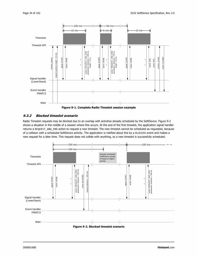
Page 34 of 102 S332 SoftDevice Specification, Rev 2.0
D00001680 thisisant.com
Figure 9-1. Complete Radio Timeslot session example
9.3.2 Blocked timeslot scenario
Radio Timeslot requests may be blocked due to an overlap with activities already scheduled by the SoftDevice. Figure 9-2
shows a situation in the middle of a session where this occurs. At the end of the first timeslot, the application signal handler
returns a REQUEST_AND_END action to request a new timeslot. The new timeslot cannot be scheduled as requested, because
of a collision with a scheduled SoftDevice activity. The application is notified about this by a BLOCKED event and makes a
new request for a later time. This request does not collide with anything, so a new timeslot is successfully scheduled.
Figure 9-2. Blocked timeslot scenario
Main
Event handler
(App(L))
Signal handler
(LowerStack)
Timeslot API
Timeslots
sessio
n_
op
en()
req
uest
(ea
rlie
st,
le
ngth
= 1
0 m
s)
sig
nal: S
TA
RT
< .
. . .
>
actio
n:
RE
QU
ES
T_
AN
D_
EN
D
pa
ram
ete
rs:
dis
tance =
10
0 m
s,
len
gth
= 5
ms
< .
. . .
>
actio
n:
RE
QU
ES
T_
AN
D_
EN
D
pa
ram
ete
rs:
dis
tance =
50
ms,
len
gth
= 1
0 m
s
< .
. . .
>
actio
n:
EN
D
even
t: I
DLE
sessio
n_
clo
se
()
even
t: C
LO
SE
D
actio
n:
NO
NE
10 ms
100 ms
5 ms
50 ms
10 ms
sig
nal: S
TA
RT
actio
n:
NO
NE
sig
nal: S
TA
RT
actio
n:
NO
NE
Main
Event handler
(App(L))
Signal handler
(LowerStack)
Timeslot API
Timeslots
sig
nal: S
TA
RT
< .
. . .
>
actio
n:
RE
QU
ES
T_
AN
D_
EN
D
pa
ram
ete
rs:
dis
tance =
10
0 m
S
< .
. . .
>
actio
n:
RE
QU
ES
T_
AN
D_
EN
D
pa
ram
ete
rs:
dis
tance =
10
0 m
s
even
t: B
LO
CK
ED
reque
st
(dis
tance =
20
0 m
s)
actio
n:
NO
NE
200 ms
Already scheduled
SoftDevice activity
of equal or higher
priority.
sig
nal: S
TA
RT
actio
n:
NO
NE
100 ms
100 ms
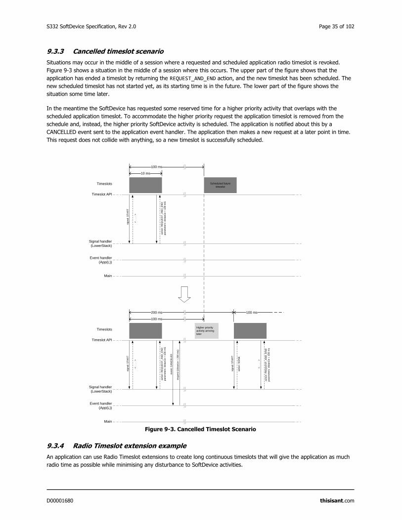
S332 SoftDevice Specification, Rev 2.0 Page 35 of 102
D00001680 thisisant.com
9.3.3 Cancelled timeslot scenario
Situations may occur in the middle of a session where a requested and scheduled application radio timeslot is revoked.
Figure 9-3 shows a situation in the middle of a session where this occurs. The upper part of the figure shows that the
application has ended a timeslot by returning the REQUEST_AND_END action, and the new timeslot has been scheduled. The
new scheduled timeslot has not started yet, as its starting time is in the future. The lower part of the figure shows the
situation some time later.
In the meantime the SoftDevice has requested some reserved time for a higher priority activity that overlaps with the
scheduled application timeslot. To accommodate the higher priority request the application timeslot is removed from the
schedule and, instead, the higher priority SoftDevice activity is scheduled. The application is notified about this by a
CANCELLED event sent to the application event handler. The application then makes a new request at a later point in time.
This request does not collide with anything, so a new timeslot is successfully scheduled.
Figure 9-3. Cancelled Timeslot Scenario
9.3.4 Radio Timeslot extension example
An application can use Radio Timeslot extensions to create long continuous timeslots that will give the application as much
radio time as possible while minimising any disturbance to SoftDevice activities.
Main
Event handler
(App(L))
Signal handler
(LowerStack)
Timeslot API
Timeslots
sig
nal: S
TA
RT
< .
. . .
>
actio
n:
RE
QU
ES
T_
AN
D_
EN
D
pa
ram
ete
rs:
dis
tance =
10
0 m
S100 ms
Scheduled future
timeslot
10 ms
Main
Event handler
(App(L))
Signal handler
(LowerStack)
Timeslot API
Timeslots
sig
nal: S
TA
RT
< .
. . .
>
actio
n:
RE
QU
ES
T_
AN
D_
EN
D
pa
ram
ete
rs:
dis
tance =
10
0 m
S
< .
. . .
>
actio
n:
RE
QU
ES
T_
AN
D_
EN
D
pa
ram
ete
rs:
dis
tance
= 1
00 m
s
even
t: C
AN
CE
LE
D
reque
st
(dis
tance =
20
0 m
s)
200 ms
Higher priority
activity arriving
later
sig
nal: S
TA
RT
actio
n:
NO
NE
100 ms
100 ms
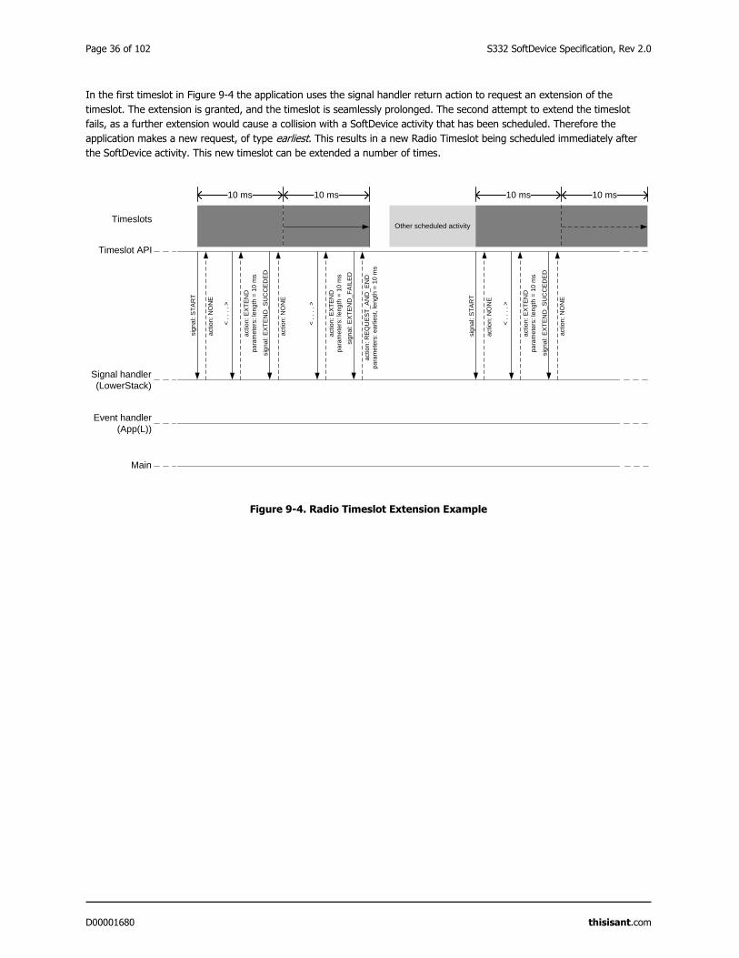
Page 36 of 102 S332 SoftDevice Specification, Rev 2.0
D00001680 thisisant.com
In the first timeslot in Figure 9-4 the application uses the signal handler return action to request an extension of the
timeslot. The extension is granted, and the timeslot is seamlessly prolonged. The second attempt to extend the timeslot
fails, as a further extension would cause a collision with a SoftDevice activity that has been scheduled. Therefore the
application makes a new request, of type earliest. This results in a new Radio Timeslot being scheduled immediately after
the SoftDevice activity. This new timeslot can be extended a number of times.
Figure 9-4. Radio Timeslot Extension Example
Main
Event handler
(App(L))
Signal handler
(LowerStack)
Timeslot API
Timeslots
sig
nal: S
TA
RT
< .
. . .
>
actio
n:
EX
TE
ND
pa
ram
ete
rs:
len
gth
= 1
0 m
s
actio
n:
NO
NE
Other scheduled activity
10 ms
sig
nal: E
XT
EN
D_
SU
CC
ED
ED
actio
n:
NO
NE
10 ms
< .
. . .
>
actio
n:
EX
TE
ND
pa
ram
ete
rs:
len
gth
= 1
0 m
s
sig
nal: E
XT
EN
D_
FA
ILE
D
actio
n:
RE
QU
ES
T_
AN
D_
EN
D
pa
ram
ete
rs:
ea
rlie
st,
le
ngth
= 1
0 m
s
10 ms
sig
nal: S
TA
RT
< .
. . .
>
actio
n:
EX
TE
ND
pa
ram
ete
rs:
len
gth
= 1
0 m
s
actio
n:
NO
NE
sig
nal: E
XT
EN
D_
SU
CC
ED
ED
actio
n:
NO
NE
10 ms
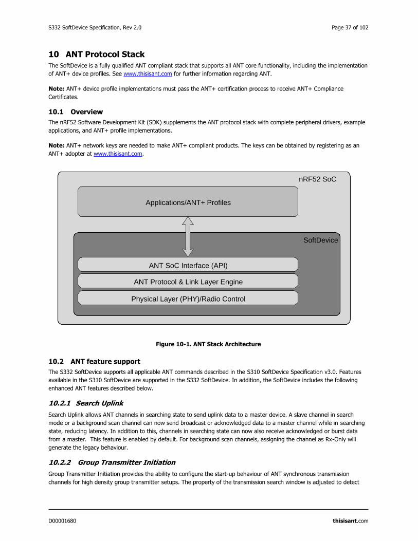
S332 SoftDevice Specification, Rev 2.0 Page 37 of 102
D00001680 thisisant.com
10 ANT Protocol Stack
The SoftDevice is a fully qualified ANT compliant stack that supports all ANT core functionality, including the implementation
of ANT+ device profiles. See www.thisisant.com for further information regarding ANT.
Note: ANT+ device profile implementations must pass the ANT+ certification process to receive ANT+ Compliance
Certificates.
10.1 Overview
The nRF52 Software Development Kit (SDK) supplements the ANT protocol stack with complete peripheral drivers, example
applications, and ANT+ profile implementations.
Note: ANT+ network keys are needed to make ANT+ compliant products. The keys can be obtained by registering as an
ANT+ adopter at www.thisisant.com.
Figure 10-1. ANT Stack Architecture
10.2 ANT feature support
The S332 SoftDevice supports all applicable ANT commands described in the S310 SoftDevice Specification v3.0. Features
available in the S310 SoftDevice are supported in the S332 SoftDevice. In addition, the SoftDevice includes the following
enhanced ANT features described below.
10.2.1 Search Uplink
Search Uplink allows ANT channels in searching state to send uplink data to a master device. A slave channel in search
mode or a background scan channel can now send broadcast or acknowledged data to a master channel while in searching
state, reducing latency. In addition to this, channels in searching state can now also receive acknowledged or burst data
from a master. This feature is enabled by default. For background scan channels, assigning the channel as Rx-Only will
generate the legacy behaviour.
10.2.2 Group Transmitter Initiation
Group Transmitter Initiation provides the ability to configure the start-up behaviour of ANT synchronous transmission
channels for high density group transmitter setups. The property of the transmission search window is adjusted to detect
nRF52 SoC
Applications/ANT+ Profiles
SoftDevice
Physical Layer (PHY)/Radio Control
ANT SoC Interface (API)
ANT Protocol & Link Layer Engine
Page 38 of 102 S332 SoftDevice Specification, Rev 2.0
D00001680 thisisant.com
for adjacent interference or possible collision sources before starting transmission. Using this feature will help minimize
transmitter interference when adding transmitters to a high density group transmitter setup at the cost of increased power
consumption and start-up latency.
10.2.3 High Duty Search
High Duty Search uses the entire available resources of the radio to search for a master device. The effect is that latency to
acquire the master device is significantly reduced to an average of ½ of the elapsed time between transmitted messages
assuming ideal RF conditions. I.e. for a message period of 4Hz, the average acquisition latency is ½ of 0.25 seconds: 0.125
seconds. This mode of operation has high power consumption while in search and should only be used in applications that
have considerable power resources available. This feature can be enabled for standard searches and for background
scanning.
10.2.4 Time Sync
Time Sync allows independent devices to synchronize the time at which an event was generated on the transmitting device
in the time base of the receiving device(s). Using this method multiple devices can synchronize themselves within two clock
ticks. Some examples of usage could include synchronizing data between sensors, display elements on devices, or
movement in autonomous robotics. Time sync can be used concurrently on multiple channels.
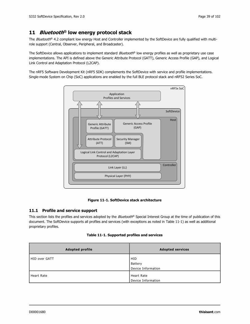
S332 SoftDevice Specification, Rev 2.0 Page 39 of 102
D00001680 thisisant.com
11 Bluetooth® low energy protocol stack
The Bluetooth® 4.2 compliant low energy Host and Controller implemented by the SoftDevice are fully qualified with multi-
role support (Central, Observer, Peripheral, and Broadcaster).
The SoftDevice allows applications to implement standard Bluetooth® low energy profiles as well as proprietary use case
implementations. The API is defined above the Generic Attribute Protocol (GATT), Generic Access Profile (GAP), and Logical
Link Control and Adaptation Protocol (L2CAP).
The nRF5 Software Development Kit (nRF5 SDK) complements the SoftDevice with service and profile implementations.
Single-mode System on Chip (SoC) applications are enabled by the full BLE protocol stack and nRF52 Series SoC.
Figure 11-1. SoftDevice stack architecture
11.1 Profile and service support
This section lists the profiles and services adopted by the Bluetooth® Special Interest Group at the time of publication of this
document. The SoftDevice supports all profiles and services (with exceptions as noted in Table 11-1) as well as additional
proprietary profiles.
Table 11-1. Supported profiles and services
Adopted profile Adopted services
HID over GATT HID
Battery
Device Information
Heart Rate Heart Rate
Device Information
nRF5x SoC
SoftDevice
Host
Controller
Physical Layer (PHY)
Generic Attribute Profile (GATT)
Attribute Protocol (ATT)
Logical Link Control and Adaptation Layer Protocol (L2CAP)
Link Layer (LL)
Security Manager (SM)
Generic Access Profile(GAP)
ApplicationProfiles and Services

Page 40 of 102 S332 SoftDevice Specification, Rev 2.0
D00001680 thisisant.com
Adopted profile Adopted services
Proximity Link Loss
Immediate Alert
Tx Power
Blood Pressure Blood Pressure
Device Information
Health Thermometer Health Thermometer
Device Information
Glucose Glucose
Device Information
Phone Alert Status Phone Alert Status
Alert Notification Alert Notification
Time Current Time
Next DST Change
Reference Time Update
Find Me Immediate Alert
Cycling Speed and Cadence Cycling Speed and Cadence
Device Information
Running Speed and Cadence Running Speed and Cadence
Device Information
Location and Navigation Location and Navigation
Cycling Power Cycling Power
Scan Parameters Scan Parameters
Weight Scale Weight Scale
Body Composition
User Data
Device Information
Continuous Glucose Monitoring Continuous Glucose Monitoring
Bond Management
Device Information
Environmental Sensing Environmental Sensing
Pulse Oximeter Pulse Oximeter
Device Information
Bond Management
Battery
Current Time
Object Transfer
(Currently not supported by the SoftDevice)
Object Transfer
Automation IO Automation IO
Indoor Positioning
Internet Protocol Support
(Currently not supported by the SoftDevice)
S332 SoftDevice Specification, Rev 2.0 Page 41 of 102
D00001680 thisisant.com
Important: Examples for selected profiles and services are available in the nRF5 SDK. See the nRF5 SDK documentation
for details.
11.2 Bluetooth® low energy features
The BLE protocol stack in the SoftDevice has been designed to provide an abstract but flexible interface for application
development for Bluetooth® low energy devices.
GAP, GATT, SM, and L2CAP are implemented in the SoftDevice and managed through the API. The SoftDevice implements
GAP and GATT procedures and modes that are common to most profiles such as the handling of discovery, connection, data
transfer, and bonding.
The BLE API is consistent across Bluetooth® role implementations where common features have the same interface. The
following tables describe the features found in the BLE protocol stack.
Table 11-2. API features in the BLE stack
API features Description
Interface to:
GATT / GAP
Consistency between APIs including shared data
formats.
Attribute table sizing, population and access Full flexibility to size the attribute table at application
compile time and to populate it at run time. Attribute
removal is not supported.
Asynchronous and event driven Thread-safe function and event model enforced by the
architecture.
Vendor-specific (128-bit) UUIDs for proprietary profiles Compact, fast and memory efficient management of
128-bit UUIDs.
Packet flow control Full application control over data buffers to ensure
maximum throughput.
Table 11-3. GAP features in the BLE stack
GAP features Description
Multi-role Central, Peripheral, Observer, and Broadcaster can run
concurrently with a connection.
Multiple bond support Keys and peer information stored in application space.
No restrictions in stack implementation.
Security Mode (SM) 1:
Levels 1, 2 & 3
Support for all levels of SM 1.
Page 42 of 102 S332 SoftDevice Specification, Rev 2.0
D00001680 thisisant.com
Table 11-4. GATT features in the BLE stack
GATT features Description
Full GATT Server Support for eight concurrent ATT server sessions.
Includes configurable Service Changed support.
Support for authorization Enables control points.
Enables freshest data.
Enables GAP authorization.
Full GATT Client Flexible data management options for packet
transmission with either fine control or abstract
management.
Implemented GATT Sub-procedures Exchange MTU
Discover all Primary Services.
Discover Primary Service by Service UUID.
Find included Services.
Discover All Characteristics of a Service.
Discover Characteristics by UUID.
Discover All Characteristic Descriptors.
Read Characteristic Value
Read using Characteristic UUID.
Read Long Characteristic Values.
Read Multiple Characteristic Values (Client only).
Write Without Response.
Write Characteristic Value.
Notifications.
Indications.
Read Characteristic Descriptors.
Read Long Characteristic Descriptors.
Write Characteristic Descriptors.
Write Long Characteristic Values.
Write Long Characteristic Descriptors.
Reliable Writes.
Table 11-5. Security Manager (SM) features in the BLE stack
Security Manager features Description
Flexible key generation and storage for reduced memory
requirements.
Keys are stored directly in application memory to avoid
unnecessary copies and memory constraints.
Authenticated MITM (Man in the middle) protection Allows for per-link elevation of the encryption security
level.
Pairing methods:
Just works, Numeric Comparison, Passkey Entry and Out of
Band
API provides the application full control of the pairing
sequences.
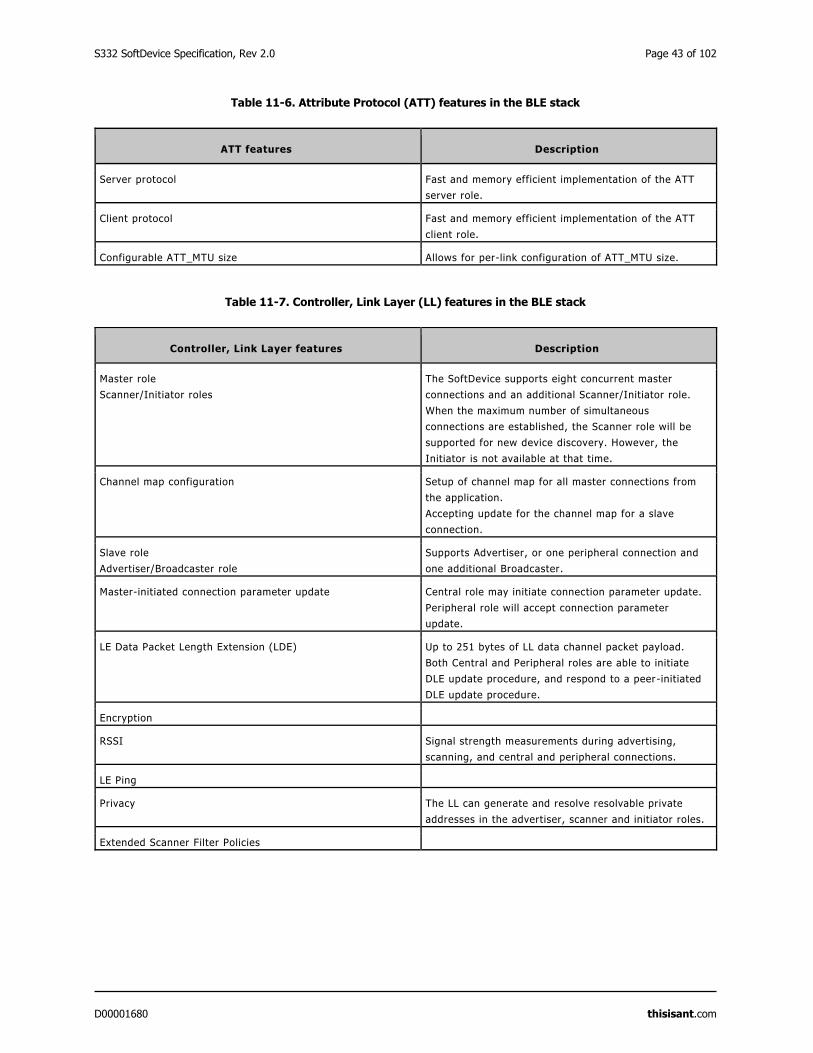
S332 SoftDevice Specification, Rev 2.0 Page 43 of 102
D00001680 thisisant.com
Table 11-6. Attribute Protocol (ATT) features in the BLE stack
ATT features Description
Server protocol Fast and memory efficient implementation of the ATT
server role.
Client protocol Fast and memory efficient implementation of the ATT
client role.
Configurable ATT_MTU size Allows for per-link configuration of ATT_MTU size.
Table 11-7. Controller, Link Layer (LL) features in the BLE stack
Controller, Link Layer features Description
Master role
Scanner/Initiator roles
The SoftDevice supports eight concurrent master
connections and an additional Scanner/Initiator role.
When the maximum number of simultaneous
connections are established, the Scanner role will be
supported for new device discovery. However, the
Initiator is not available at that time.
Channel map configuration Setup of channel map for all master connections from
the application.
Accepting update for the channel map for a slave
connection.
Slave role
Advertiser/Broadcaster role
Supports Advertiser, or one peripheral connection and
one additional Broadcaster.
Master-initiated connection parameter update Central role may initiate connection parameter update.
Peripheral role will accept connection parameter
update.
LE Data Packet Length Extension (LDE) Up to 251 bytes of LL data channel packet payload.
Both Central and Peripheral roles are able to initiate
DLE update procedure, and respond to a peer-initiated
DLE update procedure.
Encryption
RSSI Signal strength measurements during advertising,
scanning, and central and peripheral connections.
LE Ping
Privacy The LL can generate and resolve resolvable private
addresses in the advertiser, scanner and initiator roles.
Extended Scanner Filter Policies
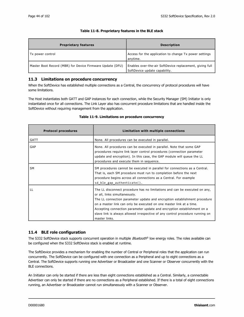
Page 44 of 102 S332 SoftDevice Specification, Rev 2.0
D00001680 thisisant.com
Table 11-8. Proprietary features in the BLE stack
Proprietary features Description
Tx power control Access for the application to change Tx power settings
anytime.
Master Boot Record (MBR) for Device Firmware Update (DFU) Enables over-the-air SoftDevice replacement, giving full
SoftDevice update capability.
11.3 Limitations on procedure concurrency
When the SoftDevice has established multiple connections as a Central, the concurrency of protocol procedures will have
some limitations.
The Host instantiates both GATT and GAP instances for each connection, while the Security Manager (SM) Initiator is only
instantiated once for all connections. The Link Layer also has concurrent procedure limitations that are handled inside the
SoftDevice without requiring management from the application.
Table 11-9. Limitations on procedure concurrency
Protocol procedures Limitation with multiple connections
GATT None. All procedures can be executed in parallel.
GAP None. All procedures can be executed in parallel. Note that some GAP
procedures require link layer control procedures (connection parameter
update and encryption). In this case, the GAP module will queue the LL
procedures and execute them in sequence.
SM SM procedures cannot be executed in parallel for connections as a Central.
That is, each SM procedure must run to completion before the next
procedure begins across all connections as a Central. For example
sd_ble_gap_authenticate().
LL The LL disconnect procedure has no limitations and can be executed on any,
or all, links simultaneously.
The LL connection parameter update and encryption establishment procedure
on a master link can only be executed on one master link at a time.
Accepting connection parameter update and encryption establishment on a
slave link is always allowed irrespective of any control procedure running on
master links.
11.4 BLE role configuration
The S332 SoftDevice stack supports concurrent operation in multiple Bluetooth® low energy roles. The roles available can
be configured when the S332 SoftDevice stack is enabled at runtime.
The SoftDevice provides a mechanism for enabling the number of Central or Peripheral roles that the application can run
concurrently. The SoftDevice can be configured with one connection as a Peripheral and up to eight connections as a
Central. The SoftDevice supports running one Advertiser or Broadcaster and one Scanner or Observer concurrently with the
BLE connections.
An Initiator can only be started if there are less than eight connections established as a Central. Similarly, a connectable
Advertiser can only be started if there are no connections as a Peripheral established. If there is a total of eight connections
running, an Advertiser or Broadcaster cannot run simultaneously with a Scanner or Observer.

S332 SoftDevice Specification, Rev 2.0 Page 45 of 102
D00001680 thisisant.com
When the SoftDevice is enabled it will allocate memory for the connections that the application has requested. See section
15 for more details.
The SoftDevice supports three predetermined bandwidth levels: low, mid (medium), and high. The bandwidth levels are
defined per connection interval, so the connection interval of the connection will also affect the total bandwidth. Bandwidth
configuration is an optional feature and if the application chooses to not use the feature the SoftDevice will use default
bandwidth configurations. By default, connections as a Central will be set to medium bandwidth and connections as a
Peripheral will be set to high bandwidth. The bandwidth can also be configured individually for both transmitting and
receiving, allowing for more fine-grained control with asymmetric bandwidth.
When using the bandwidth feature of the SoftDevice the application needs to provide the SoftDevice with information about
the bandwidth configurations that the application intends to use. This is done when enabling the BLE stack and will allow
the SoftDevice to allocate memory pools large enough to fit the bandwidth configurations of all connections. Otherwise
connections can fail to be established because there is not enough memory available for the bandwidth requirement of the
connection. If the application changes the bandwidth configuration when the link is disconnected it might fail to reconnect
because of internal fragmentation of the SoftDevice memory pools. It is therefore recommended to disconnect all links
when changing the bandwidth configurations of links.
In addition to the bandwidth feature, connection bandwidth can be increased by enabling Connection Event Length
Extension. See section 16.7 for more information. Enabling Connection Event Length Extension does not increase the size of
the SoftDevice memory pools.
Bandwidth and multilink scheduling can both affect each other. See section 16 for details. Knowledge of multilink scheduling
can be used to get predictable performance on all links. Refer to section BLE suggested intervals and windows16.10 for
recommended configurations.

Page 46 of 102 S332 SoftDevice Specification, Rev 2.0
D00001680 thisisant.com
12 Radio Notification
The Radio Notification is a configurable feature that enables ACTIVE and INACTIVE (nACTIVE) signals from the SoftDevice
to the application notifying it when the radio is in use.
12.1 Radio Notification Signals
The Radio Notification signals are sent prior to and at the end of SoftDevice Radio Events or application Radio Events11, i.e.
defined time intervals of radio operation.
Radio notifications behave differently when Connection Event Length Extension is enabled. Section 12.3.4 explains the
behaviour when this feature is enabled. Otherwise the presented material assumes that the feature is disabled
To ensure that the Radio Notification signals behave in a consistent way, configuring Radio Notification signals shall only be
done when the SoftDevice is in an idle state with no protocol stack or other SoftDevice activity in progress. Therefore, it is
recommended that the Radio Notification signals be configured immediately after the SoftDevice has been enabled.
If it is enabled, the ACTIVE signal is sent before the Radio Event starts. Similarly, if the nACTIVE signal is enabled, it is sent
at the end of the Radio Event. These signals can be used by the application developer to synchronize the application logic
with the radio activity. For example, the ACTIVE signal can be used to switch off external devices to manage peak current
drawn during periods when the radio is on, or to trigger sensor data collection for transmission during the upcoming Radio
Event.
The notification signals are sent using a software interrupt, as specified in Table 7-3. Refer to Table 12-1 for the notation
that is used in this section.
When there is sufficient time between Radio Events (tgap > tndist), both the ACTIVE and nACTIVE notification signals will be
present at each Radio Event. Figure 12-1 illustrates an example of this scenario with two Radio Events. The figure also
illustrates the ACTIVE and nACTIVE signals with respect to the Radio Events.
When there is not sufficient time between the Radio Events (tgap < tndist), the ACTIVE and nACTIVE notification signals will
be skipped. There will still be an ACTIVE signal before the first event and a nACTIVE signal after the last event. This is
shown in Figure 12-2.
Figure 12-1. Two Radio Events with ACTIVE and nACTIVE Signals
11 Application Radio Events are defined as Radio Timeslots (section 9).
ACTIVE
P Radio activity
tprep tevent
nACTIVE
P
tndist
Radio activity
tprep tevent
tgap
ACTIVEnACTIVE
tndist

S332 SoftDevice Specification, Rev 2.0 Page 47 of 102
D00001680 thisisant.com
Figure 12-2. Two radio events where tgap is too small and the notification signals will not be available between the events
Table 12-1. Notation and terminology for the Radio Notification used in this chapter
Label Description Notes
ACTIVE The ACTIVE signal prior to a Radio Event.
nACTIVE The nACTIVE signal after a Radio Event. Because both ACTIVE and nACTIVE use the
same software interrupt, it is up to the
application to manage them. If both ACTIVE
and nACTIVE are configured ON by the
application, there will always be an ACTIVE
signal before a nACTIVE signal.
P SoftDevice CPU processing at interrupt priority
level 0 between the ACTIVE signal and the
start of the Radio Event.
The CPU processing may occur anytime within
the tprep interval, before the start of the Radio
Event.
Rx Reception of packet.
Tx Transmission of packet.
tevent The total time of a Radio Event.
tgap The time between the end of one Radio Event
and the start of the following one.
tndist The notification distance - the time between
the ACTIVE signal and the first Rx/Tx in a
Radio Event.
This time is configurable by the application
developer.
tprep The time before first Rx/Tx available to the
protocol stack to prepare and configure the
radio.
The application will be interrupted by a
SoftDevice interrupt handler at priority level 0
tprep time units before the start of the Radio
Event.
Important: All packet data to send in an
event should have been sent to the stack tprep
before the Radio Event starts.
tP Time used for preprocessing before the Radio
Event.
ACTIVE
P
tndist
Radio activity
tprep tevent
nACTIVE
P Radio activity
tprep tevent
tgap
tndist
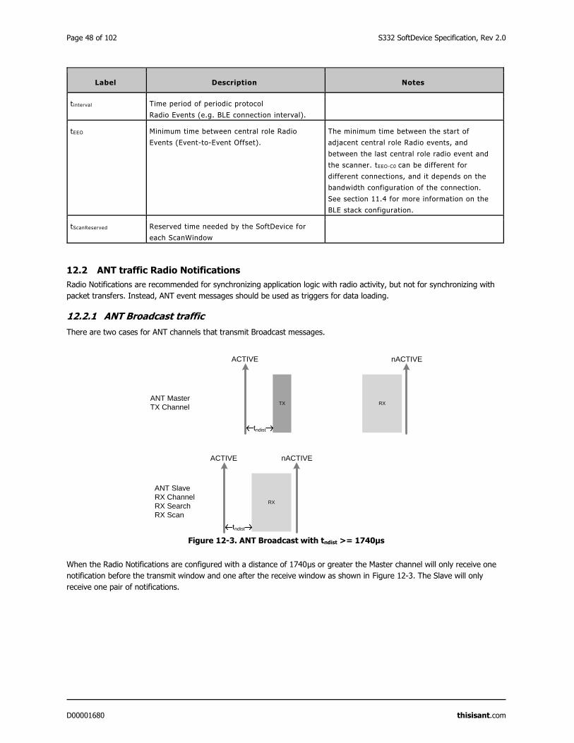
Page 48 of 102 S332 SoftDevice Specification, Rev 2.0
D00001680 thisisant.com
Label Description Notes
t interval Time period of periodic protocol
Radio Events (e.g. BLE connection interval).
tEEO Minimum time between central role Radio
Events (Event-to-Event Offset).
The minimum time between the start of
adjacent central role Radio events, and
between the last central role radio event and
the scanner. tEEO-C0 can be different for
different connections, and it depends on the
bandwidth configuration of the connection.
See section 11.4 for more information on the
BLE stack configuration.
tScanReserved Reserved time needed by the SoftDevice for
each ScanWindow
12.2 ANT traffic Radio Notifications
Radio Notifications are recommended for synchronizing application logic with radio activity, but not for synchronizing with
packet transfers. Instead, ANT event messages should be used as triggers for data loading.
12.2.1 ANT Broadcast traffic
There are two cases for ANT channels that transmit Broadcast messages.
Figure 12-3. ANT Broadcast with tndist >= 1740μs
When the Radio Notifications are configured with a distance of 1740μs or greater the Master channel will only receive one
notification before the transmit window and one after the receive window as shown in Figure 12-3. The Slave will only
receive one pair of notifications.
TX RX
ACTIVE nACTIVE
tndist
RX
nACTIVEACTIVE
tndist
ANT Master
TX Channel
ANT Slave
RX Channel
RX Search
RX Scan
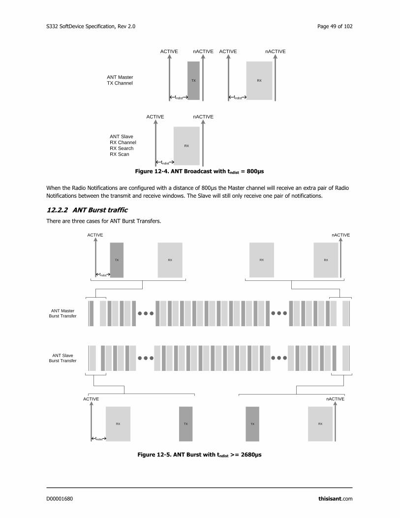
S332 SoftDevice Specification, Rev 2.0 Page 49 of 102
D00001680 thisisant.com
Figure 12-4. ANT Broadcast with tndist = 800μs
When the Radio Notifications are configured with a distance of 800μs the Master channel will receive an extra pair of Radio
Notifications between the transmit and receive windows. The Slave will still only receive one pair of notifications.
12.2.2 ANT Burst traffic
There are three cases for ANT Burst Transfers.
Figure 12-5. ANT Burst with tndist >= 2680μs
TX RX
ACTIVE
tndist
RX
nACTIVE
RX
RX
ACTIVE
tndist
TX RX
nACTIVE
ANT Master
Burst Transfer
ANT Slave
Burst Transfer
TX
TX RX
ACTIVE nACTIVE
tndist
nACTIVE ACTIVE
tndist
RX
nACTIVEACTIVE
tndist
ANT Master
TX Channel
ANT Slave
RX Channel
RX Search
RX Scan
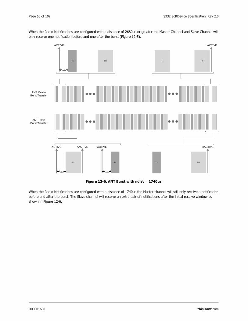
Page 50 of 102 S332 SoftDevice Specification, Rev 2.0
D00001680 thisisant.com
When the Radio Notifications are configured with a distance of 2680μs or greater the Master Channel and Slave Channel will
only receive one notification before and one after the burst (Figure 12-5).
Figure 12-6. ANT Burst with ndist = 1740μs
When the Radio Notifications are configured with a distance of 1740μs the Master channel will still only receive a notification
before and after the burst. The Slave channel will receive an extra pair of notifications after the initial receive window as
shown in Figure 12-6.
TX RX
ACTIVE
tndist
RX
nACTIVE
RX
RX
ACTIVE
tndist
TX
nACTIVEACTIVE
tndist
nACTIVE
ANT Master
Burst Transfer
ANT Slave
Burst Transfer
RXTX
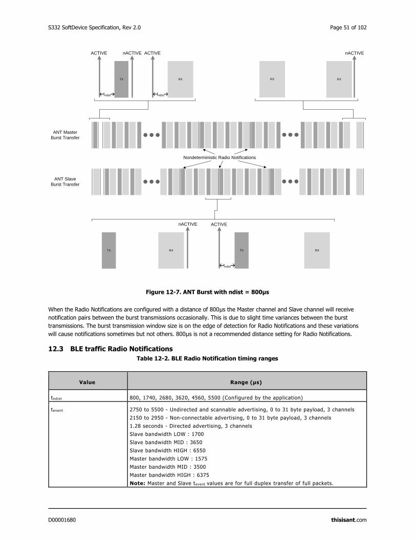
S332 SoftDevice Specification, Rev 2.0 Page 51 of 102
D00001680 thisisant.com
Figure 12-7. ANT Burst with ndist = 800μs
When the Radio Notifications are configured with a distance of 800μs the Master channel and Slave channel will receive
notification pairs between the burst transmissions occasionally. This is due to slight time variances between the burst
transmissions. The burst transmission window size is on the edge of detection for Radio Notifications and these variations
will cause notifications sometimes but not others. 800μs is not a recommended distance setting for Radio Notifications.
12.3 BLE traffic Radio Notifications
Table 12-2. BLE Radio Notification timing ranges
Value Range (μs)
tndist 800, 1740, 2680, 3620, 4560, 5500 (Configured by the application)
tevent 2750 to 5500 - Undirected and scannable advertising, 0 to 31 byte payload, 3 channels
2150 to 2950 - Non-connectable advertising, 0 to 31 byte payload, 3 channels
1.28 seconds - Directed advertising, 3 channels
Slave bandwidth LOW : 1700
Slave bandwidth MID : 3650
Slave bandwidth HIGH : 6550
Master bandwidth LOW : 1575
Master bandwidth MID : 3500
Master bandwidth HIGH : 6375
Note: Master and Slave tevent values are for full duplex transfer of full packets.
TX RX
ACTIVE
tndist
RX
nACTIVE
RX
RX TX RXTX
ACTIVE
tndist
nACTIVE
ACTIVE
tndist
nACTIVE
ANT Master
Burst Transfer
ANT Slave
Burst Transfer
Nondeterministic Radio Notifications
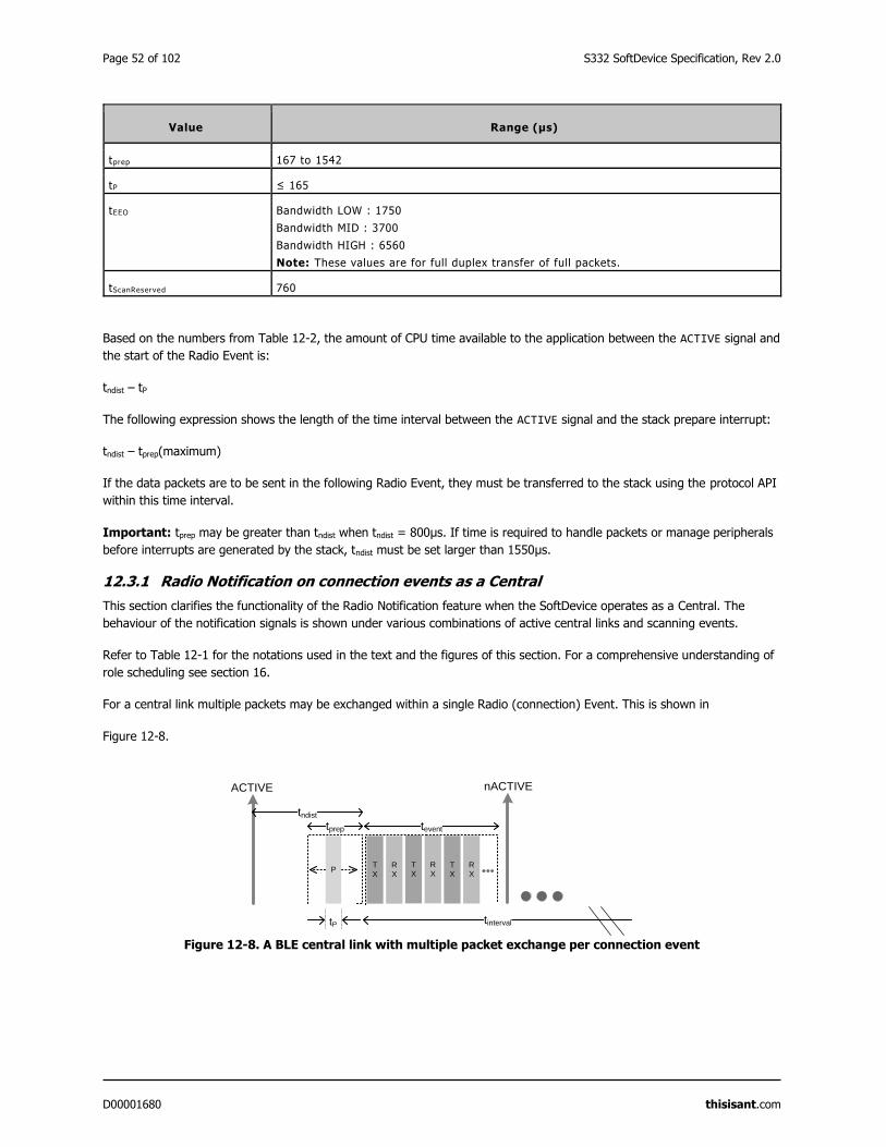
Page 52 of 102 S332 SoftDevice Specification, Rev 2.0
D00001680 thisisant.com
Value Range (μs)
tprep 167 to 1542
tP ≤ 165
tEEO Bandwidth LOW : 1750
Bandwidth MID : 3700
Bandwidth HIGH : 6560
Note: These values are for full duplex transfer of full packets.
tScanReserved 760
Based on the numbers from Table 12-2, the amount of CPU time available to the application between the ACTIVE signal and
the start of the Radio Event is:
tndist – tP
The following expression shows the length of the time interval between the ACTIVE signal and the stack prepare interrupt:
tndist – tprep(maximum)
If the data packets are to be sent in the following Radio Event, they must be transferred to the stack using the protocol API
within this time interval.
Important: tprep may be greater than tndist when tndist = 800μs. If time is required to handle packets or manage peripherals
before interrupts are generated by the stack, tndist must be set larger than 1550μs.
12.3.1 Radio Notification on connection events as a Central
This section clarifies the functionality of the Radio Notification feature when the SoftDevice operates as a Central. The
behaviour of the notification signals is shown under various combinations of active central links and scanning events.
Refer to Table 12-1 for the notations used in the text and the figures of this section. For a comprehensive understanding of
role scheduling see section 16.
For a central link multiple packets may be exchanged within a single Radio (connection) Event. This is shown in
Figure 12-8.
Figure 12-8. A BLE central link with multiple packet exchange per connection event
T
X
R
X
ACTIVE
PT
X
R
X
T
X
R
X
nACTIVE
tinterval
tevent
tP
tprep
tndist
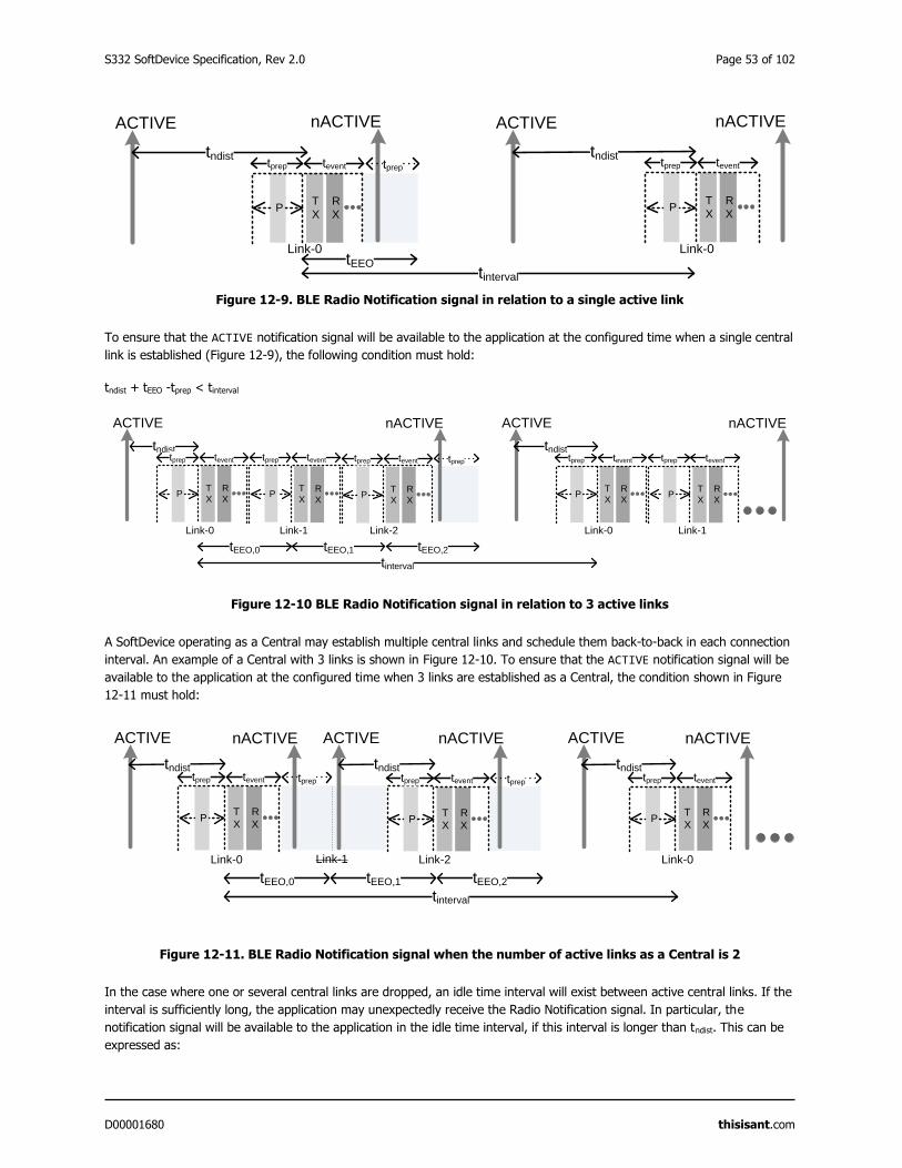
S332 SoftDevice Specification, Rev 2.0 Page 53 of 102
D00001680 thisisant.com
Figure 12-9. BLE Radio Notification signal in relation to a single active link
To ensure that the ACTIVE notification signal will be available to the application at the configured time when a single central
link is established (Figure 12-9), the following condition must hold:
tndist + tEEO -tprep < tinterval
Figure 12-10 BLE Radio Notification signal in relation to 3 active links
A SoftDevice operating as a Central may establish multiple central links and schedule them back-to-back in each connection
interval. An example of a Central with 3 links is shown in Figure 12-10. To ensure that the ACTIVE notification signal will be
available to the application at the configured time when 3 links are established as a Central, the condition shown in Figure
12-11 must hold:
Figure 12-11. BLE Radio Notification signal when the number of active links as a Central is 2
In the case where one or several central links are dropped, an idle time interval will exist between active central links. If the
interval is sufficiently long, the application may unexpectedly receive the Radio Notification signal. In particular, the
notification signal will be available to the application in the idle time interval, if this interval is longer than tndist. This can be
expressed as:
R
X
T
X
ACTIVE
P
tndisttprep
tinterval
ACTIVE nACTIVE
tevent
tEEO,0
Link-0
R
X
T
XP
Link-1
teventtprep
R
X
T
XP
tevent
Link-2
tprep
tEEO,1 tEEO,2
R
X
T
XP
tndisttprep tevent
Link-0
R
X
T
XP
Link-1
teventtprep
nACTIVE
tprep
ACTIVE
R
X
T
X
ACTIVE
P
tndisttprep
tinterval
ACTIVE nACTIVE
tevent
tEEO,0
Link-0
R
X
T
XP
tevent
Link-2
tndisttprep
tEEO,1 tEEO,2
R
X
T
XP
tndisttprep tevent
Link-0
nACTIVE
Link-1
nACTIVE
tpreptprep
R
X
T
X
ACTIVE
P
tndisttprep
tinterval
ACTIVE
tndist
nACTIVE
tevent
R
X
T
XP
tprep tevent
tEEO
Link-0 Link-0
nACTIVE
tprep
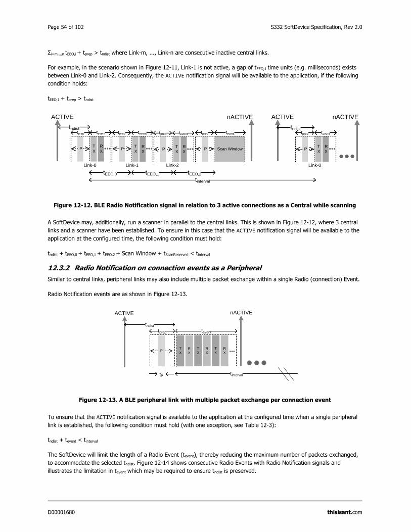
Page 54 of 102 S332 SoftDevice Specification, Rev 2.0
D00001680 thisisant.com
Σi=m,...n tEEO,i + tprep > tndist where Link-m, ..., Link-n are consecutive inactive central links.
For example, in the scenario shown in Figure 12-11, Link-1 is not active, a gap of tEEO,1 time units (e.g. milliseconds) exists
between Link-0 and Link-2. Consequently, the ACTIVE notification signal will be available to the application, if the following
condition holds:
tEEO,1 + tprep > tndist
Figure 12-12. BLE Radio Notification signal in relation to 3 active connections as a Central while scanning
A SoftDevice may, additionally, run a scanner in parallel to the central links. This is shown in Figure 12-12, where 3 central
links and a scanner have been established. To ensure in this case that the ACTIVE notification signal will be available to the
application at the configured time, the following condition must hold:
tndist + tEEO,0 + tEEO,1 + tEEO,2 + Scan Window + tScanReserved < tinterval
12.3.2 Radio Notification on connection events as a Peripheral
Similar to central links, peripheral links may also include multiple packet exchange within a single Radio (connection) Event.
Radio Notification events are as shown in Figure 12-13.
Figure 12-13. A BLE peripheral link with multiple packet exchange per connection event
To ensure that the ACTIVE notification signal is available to the application at the configured time when a single peripheral
link is established, the following condition must hold (with one exception, see Table 12-3):
tndist + tevent < tinterval
The SoftDevice will limit the length of a Radio Event (tevent), thereby reducing the maximum number of packets exchanged,
to accommodate the selected tndist. Figure 12-14 shows consecutive Radio Events with Radio Notification signals and
illustrates the limitation in tevent which may be required to ensure tndist is preserved.
R
X
T
X
ACTIVE
P
tndisttprep
nACTIVE
tinterval
ACTIVE nACTIVE
tevent
tEEO,0
Link-0
R
X
T
XP
Link-1
teventtprep
R
X
T
XP
tevent
Link-2
tprep
tEEO,1 tEEO,2
R
X
T
XP
tndisttprep tevent
Link-0
P
tprep
Scan Window
tevent
T
X
R
X
ACTIVE
PT
X
R
X
T
X
R
X
nACTIVE
tinterval
tevent
tP
tprep
tndist
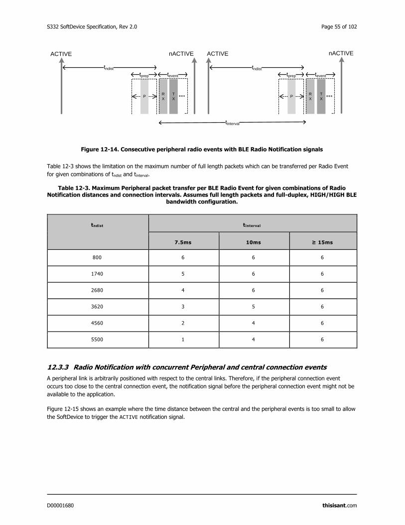
S332 SoftDevice Specification, Rev 2.0 Page 55 of 102
D00001680 thisisant.com
Figure 12-14. Consecutive peripheral radio events with BLE Radio Notification signals
Table 12-3 shows the limitation on the maximum number of full length packets which can be transferred per Radio Event
for given combinations of tndist and tinterval.
Table 12-3. Maximum Peripheral packet transfer per BLE Radio Event for given combinations of Radio Notification distances and connection intervals. Assumes full length packets and full-duplex, HIGH/HIGH BLE
bandwidth configuration.
tndist tinterval
7.5ms 10ms ≥ 15ms
800 6 6 6
1740 5 6 6
2680 4 6 6
3620 3 5 6
4560 2 4 6
5500 1 4 6
12.3.3 Radio Notification with concurrent Peripheral and central connection events
A peripheral link is arbitrarily positioned with respect to the central links. Therefore, if the peripheral connection event
occurs too close to the central connection event, the notification signal before the peripheral connection event might not be
available to the application.
Figure 12-15 shows an example where the time distance between the central and the peripheral events is too small to allow
the SoftDevice to trigger the ACTIVE notification signal.
T
X
R
X
nACTIVEACTIVE
P
tndist
tprep
tinterval
tevent
T
X
R
X
nACTIVEACTIVE
P
tndist
tprep tevent
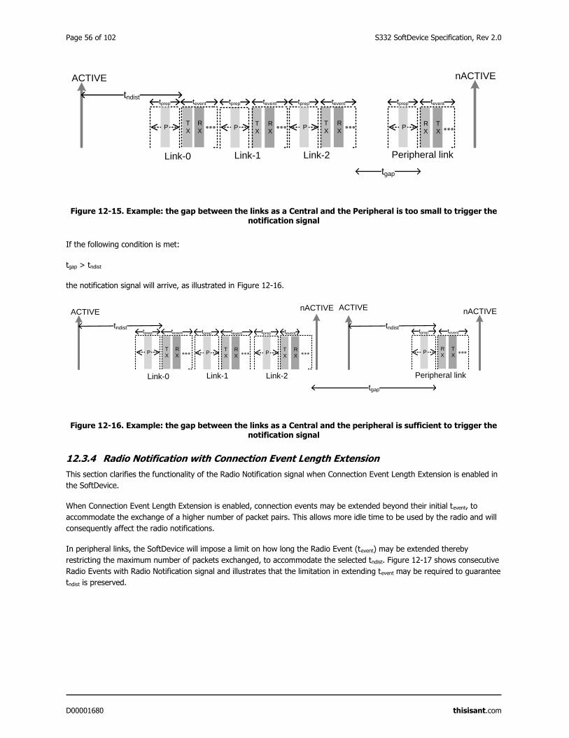
Page 56 of 102 S332 SoftDevice Specification, Rev 2.0
D00001680 thisisant.com
Figure 12-15. Example: the gap between the links as a Central and the Peripheral is too small to trigger the notification signal
If the following condition is met:
tgap > tndist
the notification signal will arrive, as illustrated in Figure 12-16.
Figure 12-16. Example: the gap between the links as a Central and the peripheral is sufficient to trigger the notification signal
12.3.4 Radio Notification with Connection Event Length Extension
This section clarifies the functionality of the Radio Notification signal when Connection Event Length Extension is enabled in
the SoftDevice.
When Connection Event Length Extension is enabled, connection events may be extended beyond their initial tevent, to
accommodate the exchange of a higher number of packet pairs. This allows more idle time to be used by the radio and will
consequently affect the radio notifications.
In peripheral links, the SoftDevice will impose a limit on how long the Radio Event (tevent) may be extended thereby
restricting the maximum number of packets exchanged, to accommodate the selected tndist. Figure 12-17 shows consecutive
Radio Events with Radio Notification signal and illustrates that the limitation in extending tevent may be required to guarantee
tndist is preserved.
tprep
R
X
T
X
ACTIVE
P
tndisttprep tevent
R
X
T
XP
tprep tevent
Link-0 Link-2
R
X
T
XP
tevent
Link-1
nACTIVE
T
X
R
XP
tprep tevent
Peripheral link
tgap
tprep
R
X
T
X
ACTIVE
P
tprep
tndisttevent
R
X
T
XP
tevent
Link-0 Link-2
R
X
T
XP
tprep tevent
Link-1
nACTIVE
T
X
R
XP
tprep tevent
Peripheral link
tgap
ACTIVE
tndist
nACTIVE
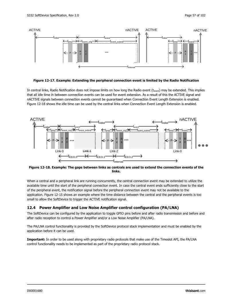
S332 SoftDevice Specification, Rev 2.0 Page 57 of 102
D00001680 thisisant.com
Figure 12-17. Example: Extending the peripheral connection event is limited by the Radio Notification
In central links, Radio Notification does not impose limits on how long the Radio event (tevent) may be extended. This implies
that all idle time in between connection events can be used for event extension. As a result of this the ACTIVE signal and
nACTIVE signals between connection events cannot be guaranteed when Connection Event Length Extension is enabled.
Figure 12-18 shows the idle time can be used by the central links when Connection Event Length Extension is enabled.
Figure 12-18. Example: The gaps between links as centrals are used to extend the connection events of the links.
When a central and a peripheral link are running concurrently, the central connection event may be extended to utilize the
available time until the start of the peripheral connection event. In case the central event ends sufficiently close to the start
of the peripheral event, the notification signal before the peripheral connection event may not be available to the
application. Figure 12-15 shows an example where the time distance between the central and the peripheral events is too
small to allow the SoftDevice to trigger the ACTIVE notification signal.
12.4 Power Amplifier and Low Noise Amplifier control configuration (PA/LNA)
The SoftDevice can be configured by the application to toggle GPIO pins before and after radio transmission and before and
after radio reception to control a Power Amplifier and/or a Low Noise Amplifier (PA/LNA).
The PA/LNA control functionality is provided by the SoftDevice protocol stack implementation and must be enabled by the
application before it can be used.
Important: In order to be used along with proprietary radio protocols that make use of the Timeslot API, the PA/LNA
control functionality needs to be implemented as part of the proprietary radio protocol stack.
T
X
R
X
nACTIVEACTIVE
P
tndist
tprep
tinterval
tevent_orig
T
X
R
X
nACTIVEACTIVE
P
tndist
tprep tevent
tevent
tevent_extend
R
X
T
X
ACTIVE
P
tndisttprep
tinterval
nACTIVE
tevent
tEEO,0
Link-0
R
X
T
XP
Link-2
tndist
tprep
tEEO,1 tEEO,2
R
X
T
XP
tevent
Link-0Link-1
tevent_orig tevent_extend
tevent
tevent_orig tevent_extend tprep
tndist
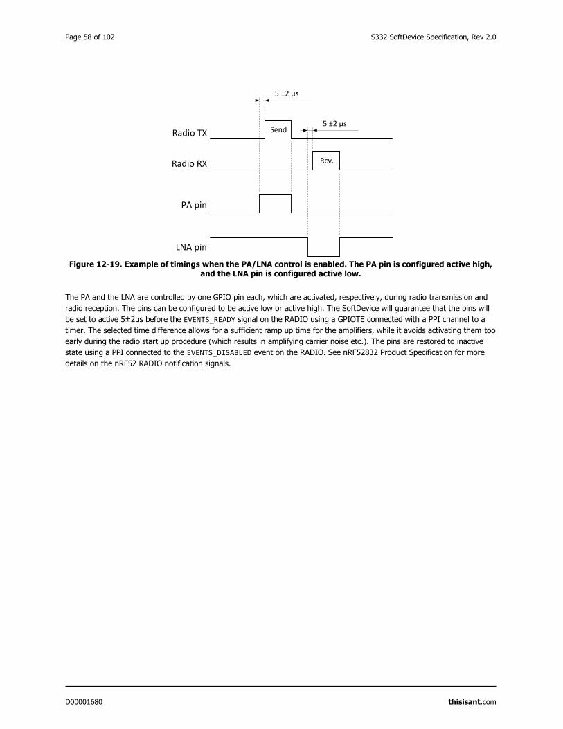
Page 58 of 102 S332 SoftDevice Specification, Rev 2.0
D00001680 thisisant.com
Figure 12-19. Example of timings when the PA/LNA control is enabled. The PA pin is configured active high, and the LNA pin is configured active low.
The PA and the LNA are controlled by one GPIO pin each, which are activated, respectively, during radio transmission and
radio reception. The pins can be configured to be active low or active high. The SoftDevice will guarantee that the pins will
be set to active 5±2μs before the EVENTS_READY signal on the RADIO using a GPIOTE connected with a PPI channel to a
timer. The selected time difference allows for a sufficient ramp up time for the amplifiers, while it avoids activating them too
early during the radio start up procedure (which results in amplifying carrier noise etc.). The pins are restored to inactive
state using a PPI connected to the EVENTS_DISABLED event on the RADIO. See nRF52832 Product Specification for more
details on the nRF52 RADIO notification signals.
PA pin
LNA pin
Radio TX
Radio RX
Send
Rcv.
5 ±2 µs
5 ±2 µs
S332 SoftDevice Specification, Rev 2.0 Page 59 of 102
D00001680 thisisant.com
13 Master Boot Record and bootloader
The SoftDevice supports the use of a bootloader. A bootloader may be used to update the firmware on the SoC.
The nRF52 software architecture includes a Master Boot Record (MBR) (Figure 3-1). The MBR is necessary in order for the
bootloader to update the SoftDevice, or to update the bootloader itself. The MBR is a required component in the system.
The inclusion of a bootloader is optional.
13.1 Master Boot Record
The main functionality of the MBR is to provide an interface to allow in-system updates of the SoftDevice and bootloader
firmware.
The Master Boot Record (MBR) module occupies a defined region in the SoC flash memory where the System Vector table
resides.
All exceptions (reset, hard fault, interrupts, SVC) are, first, processed by the MBR and then are forwarded to the appropriate
handlers (for example the bootloader or the SoftDevice exception handlers). See section 17 for more details on the interrupt
forwarding scheme.
During a firmware update process, the MBR is never erased. The MBR ensures that the bootloader can recover from any
unexpected resets during an ongoing update process.
In order to issue the SD_MBR_COMMAND_COPY_BL or SD_MBR_COMMAND_VECTOR_TABLE_BASE_SET commands to the MBR,
the UICR.NRFFW[1] register must be set to an address (MBRPARAMADDR address in Figure 13-1) corresponding to a page in
the Application Flash Region (section 5.4). If UICR.NRFFW[1] is not set the commands will return NRF_ERROR_NO_MEM. This
page will be cleared by the MBR and used to store parameters before chip reset. When the UICR.NRFFW[1] register is set,
the page it refers to must not be used by the application. If the application does not want to reserve a page for the MBR
parameters, it must leave the UICR.NRFFW[1] register set to 0xFFFFFFFF (its default value).
13.2 Bootloader
A bootloader may be used to handle in-system update procedures.
The bootloader has full access to the SoftDevice API and can be implemented like any application that uses the SoftDevice.
In particular, the bootloader can make use of the SoftDevice API for BLE and/or ANT communication.
The bootloader is supported in the SoftDevice architecture by using a configurable base address for the bootloader in the
application Flash Region. The base address is configured by setting the UICR.BOOTLOADERADDR register. The bootloader is
responsible for determining the start address of the application. It uses
sd_softdevice_vector_table_base_set(uint32_t address) to tell the SoftDevice where the application starts.
The bootloader is also responsible for keeping track of, and verifying the integrity of the SoftDevice. If an unexpected reset
occurs during an update of the SoftDevice, it is the responsibility of the bootloader to detect this and resume the update
procedure.
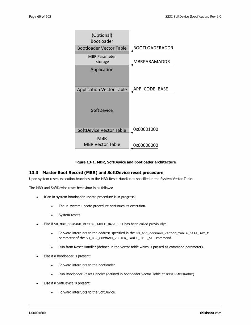
Page 60 of 102 S332 SoftDevice Specification, Rev 2.0
D00001680 thisisant.com
Figure 13-1. MBR, SoftDevice and bootloader architecture
13.3 Master Boot Record (MBR) and SoftDevice reset procedure
Upon system reset, execution branches to the MBR Reset Handler as specified in the System Vector Table.
The MBR and SoftDevice reset behaviour is as follows:
If an in-system bootloader update procedure is in progress:
The in-system update procedure continues its execution.
System resets.
Else if SD_MBR_COMMAND_VECTOR_TABLE_BASE_SET has been called previously:
Forward interrupts to the address specified in the sd_mbr_command_vector_table_base_set_t
parameter of the SD_MBR_COMMAND_VECTOR_TABLE_BASE_SET command.
Run from Reset Handler (defined in the vector table which is passed as command parameter).
Else if a bootloader is present:
Forward interrupts to the bootloader.
Run Bootloader Reset Handler (defined in bootloader Vector Table at BOOTLOADERADDR).
Else if a SoftDevice is present:
Forward interrupts to the SoftDevice.
SoftDevice
Application
Application Vector Table
SoftDevice Vector Table
APP_CODE_BASE
BOOTLOADERADDRBootloader Vector Table
(Optional)Bootloader
0x00001000
MBRMBR Vector Table 0x00000000
SoftDevice Vector Table
MBR Parameter storage MBRPARAMADDR
S332 SoftDevice Specification, Rev 2.0 Page 61 of 102
D00001680 thisisant.com
Execute the SoftDevice Reset Handler (defined in SoftDevice Vector Table at 0x00001000).
In this case, APP_CODE_BASE is hardcoded inside the SoftDevice.
The SoftDevice invokes the Application Reset Handler (as specified in the Application Vector Table at
APP_CODE_BASE).
Else system startup error:
Sleep forever.
13.4 Master Boot Record (MBR) and SoftDevice initialization procedure
The SoftDevice can be enabled by the bootloader.
The bootloader can enable the SoftDevice through the following step-by-step procedure:
1. Issuing a command for MBR to forward interrupts to the SoftDevice using sd_mbr_command() with
SD_MBR_COMMAND_INIT_SD.
2. Issuing a command for the SoftDevice to forward interrupts to the bootloader using
sd_softdevice_vector_table_base_set(uint32_t address) with BOOTLOADERADDR as parameter.
3. Enabling the SoftDevice using sd_softdevice_enable().
The bootloader can transfer the execution from itself to the application through the following step-by-step procedure:
1. Issuing a command for MBR to forward interrupts to the SoftDevice using sd_mbr_command() with
SD_MBR_COMMAND_INIT_SD, if interrupts are not forwarded to the SoftDevice.
2. Issuing sd_softdevice_disable(), to ensure that the SoftDevice is disabled.
3. Issuing a command for the SoftDevice to forward interrupts to the application using
sd_softdevice_vector_table_base_set(uint32_t address) with APP_CODE_BASE as a parameter.
4. Branching to the application Reset Handler as specified in the Application Vector Table.
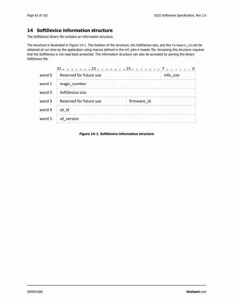
Page 62 of 102 S332 SoftDevice Specification, Rev 2.0
D00001680 thisisant.com
14 SoftDevice information structure
The SoftDevice binary file contains an information structure.
The structure is illustrated in Figure 14-1. The location of the structure, the SoftDevice size, and the firmware_id can be
obtained at run time by the application using macros defined in the nrf_sdm.h header file. Accessing this structure requires
that the SoftDevice is not read back protected. The information structure can also be accessed by parsing the binary
SoftDevice file.
Figure 14-1. SoftDevice information structure
012345678910111213141516171819202122232425262728293031
word 0
word 1
word 2
word 3
Reserved for future use
magic_number
SoftDevice size
Reserved for future use
info_size
firmware_id
word 4
word 5
sd_id
sd_version
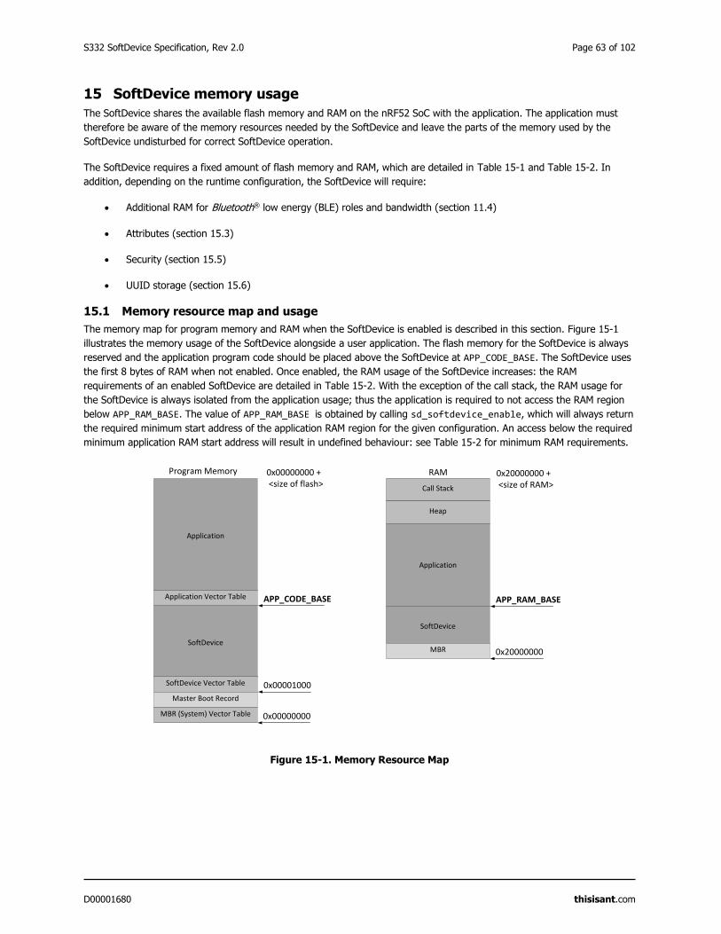
S332 SoftDevice Specification, Rev 2.0 Page 63 of 102
D00001680 thisisant.com
15 SoftDevice memory usage
The SoftDevice shares the available flash memory and RAM on the nRF52 SoC with the application. The application must
therefore be aware of the memory resources needed by the SoftDevice and leave the parts of the memory used by the
SoftDevice undisturbed for correct SoftDevice operation.
The SoftDevice requires a fixed amount of flash memory and RAM, which are detailed in Table 15-1 and Table 15-2. In
addition, depending on the runtime configuration, the SoftDevice will require:
Additional RAM for Bluetooth® low energy (BLE) roles and bandwidth (section 11.4)
Attributes (section 15.3)
Security (section 15.5)
UUID storage (section 15.6)
15.1 Memory resource map and usage
The memory map for program memory and RAM when the SoftDevice is enabled is described in this section. Figure 15-1
illustrates the memory usage of the SoftDevice alongside a user application. The flash memory for the SoftDevice is always
reserved and the application program code should be placed above the SoftDevice at APP_CODE_BASE. The SoftDevice uses
the first 8 bytes of RAM when not enabled. Once enabled, the RAM usage of the SoftDevice increases: the RAM
requirements of an enabled SoftDevice are detailed in Table 15-2. With the exception of the call stack, the RAM usage for
the SoftDevice is always isolated from the application usage; thus the application is required to not access the RAM region
below APP_RAM_BASE. The value of APP_RAM_BASE is obtained by calling sd_softdevice_enable, which will always return
the required minimum start address of the application RAM region for the given configuration. An access below the required
minimum application RAM start address will result in undefined behaviour: see Table 15-2 for minimum RAM requirements.
Figure 15-1. Memory Resource Map
SoftDevice
Application
Application Vector Table
SoftDevice Vector Table
RAMProgram Memory
SoftDevice
Application
0x20000000 + <size of RAM>Call Stack
Heap
Master Boot Record
MBR (System) Vector Table 0x00000000
0x00001000
APP_CODE_BASE
MBR 0x20000000
APP_RAM_BASE
0x00000000 + <size of flash>
Page 64 of 102 S332 SoftDevice Specification, Rev 2.0
D00001680 thisisant.com
15.1.1 Memory resource requirements
The tables below show the memory resource requirements both when the S332 SoftDevice is enabled and disabled.
Flash
Table 15-1. S332 Memory resource requirements for flash
Flash Value
Required by the SoftDevice 164kB12
Required by the MBR 4 kB
APP_CODE_BASE address (absolute value) 0x00029000
RAM
Table 15-2. S332 Memory resource requirements for RAM
RAM S332 Enabled S332 Disabled
Required by the SoftDevice (in bytes) 0x1780+ Configurable Resources
Minimum: 0x1E30 (7728)
8
APP_RAM_BASE address (minimum
required value)
0x20000000 + SoftDevice RAM
consumption
Minimum: 0x20001E30
0x20000008
Call Stack
By default, the nRF52 SoC will have a shared call stack with both application stack frames and SoftDevice stack frames,
managed by the main stack pointer (MSP).
The call stack configuration is done by the application, and the MSP gets initialized on reset to the address specified by the
application vector table entry 0. The application may, in its reset vector, configure the CPU to use the process stack pointer
(PSP) in thread mode. This configuration is optional but may be required by an operating system (OS); for example, to
isolate application threads and OS context memory. The application programmer must be aware that the SoftDevice will use
the MSP as it is always executed in exception mode.
Important: It is customary, but not required, to let the stack run downwards from the upper limit of the RAM Region.
With each release of an nRF52 SoftDevice, its maximum (worst case) call stack requirement may be updated. The
SoftDevice uses the call stack when SoftDevice interrupt handlers execute. These are asynchronous to the application, so
the application programmer must reserve call stack for the application in addition to the call stack requirement by the
SoftDevice.
121kB = 1024 bytes
S332 SoftDevice Specification, Rev 2.0 Page 65 of 102
D00001680 thisisant.com
The application must reserve sufficient space to satisfy both the application and the nRF52 SoftDevice stack memory
requirements. The nRF52 SoC has no designated hardware for detecting stack overflow. The application can use the ARM®
Cortex®-M4 MPU to implement a mechanism for stack overflow detection.
The SoftDevice does not use the ARM® Cortex®-M4 Floating-point Unit (FPU) and does not configure any floating-point
registers. Table 15-3 gives the maximum call stack size that may be consumed by the SoftDevice when not using the FPU.
Note that the SoftDevice uses multiple interrupt levels, as detailed in section 17. If the FPU is used by the application, the
processor will need to reserve memory in the stack frame for stacking the FPU registers, for each interrupt level used by the
SoftDevice. This must be accounted for when configuring the total call stack size. For more information on how the use of
multiple interrupt levels impacts the stack size when using the FPU, refer to the ARM® Cortex®-M4 processor with FPU
documentation, Application Note 298.
Table 15-3. S332 Memory resource requirements for call stack
Call stack S332 Enabled S332 Disabled
Maximum usage with FPU disabled 1536bytes (0x600) 0 bytes
Heap
There is no heap required by nRF52 SoftDevices. The application is free to allocate and use a heap without disrupting the
SoftDevice functionality.
15.2 ANT Channel Configuration
This SoftDevice allows for applications to tailor and scale the following ANT stack options using an ANT Stack Enable
Configuration API.
• Total number of ANT channels
• Number of encrypted ANT channels
• Transmit burst queue size
• Event queue size
Upon calling sd_softdevice_enable(), the ANT stack defaults to supporting one ANT channel (with encryption support),
a 64 byte transmit burst buffer, and an event queue depth of 32 events. If additional channels are needed and/or more
encrypted channels are needed and/or a larger Tx burst buffer size is needed and/or a larger event queue is needed, then
sd_ant_enable() must be used to specify the desired configuration. Application RAM memory must be supplied to the
SoftDevice in order to increase the aforementioned stack options beyond the default capabilities.
15.3 Attribute table size
The size of the attribute table can be configured through the SoftDevice API when enabling the BLE stack.
The attribute table size, ATTR_TAB_SIZE, has a default value of 0x580 bytes. Applications that require an attribute table
smaller or bigger than the default size can choose to either reduce or increase the attribute table size: the minimum
attribute table size is 0xD8 bytes. The amount of RAM reserved by the SoftDevice, and the minimum required start address
for the application RAM, APP_RAM_BASE, will then change accordingly.
For more information on how to configure the attribute table size, refer to the S332 SoftDevice API.
Page 66 of 102 S332 SoftDevice Specification, Rev 2.0
D00001680 thisisant.com
15.4 Role configuration
The SoftDevice allows the number of connections, the configuration of each connection and its role to be specified by the
application.
Role configuration (the number of connections, their role and bandwidth configuration) will determine the amount of RAM
resources used by the SoftDevice. The minimum required start address for the application RAM, APP_RAM_BASE, will change
accordingly. See section 11.4 for more details on role configuration.
15.5 Security configuration
The SoftDevice allows the number of security manager protocol (SMP) instances available for all connections operating in
central role to be specified by the application.
At least one SMP instance is needed in order to carry out SMP operations for central role connections, and an SMP instance
can be shared amongst multiple central role connections. A larger number of SMP instances will allow multiple connections
to have ongoing concurrent SMP operations, but this will result in increased RAM usage by the SoftDevice. The number of
SMP instances is specified through the ble_gap_enable_params_t type on sd_ble_enable.
15.6 Vendor specific UUID counts
The SoftDevice allows the use of vendor specific UUIDs, which are stored by the SoftDevice in the RAM that is allocated
once the SoftDevice is enabled.
The number of vendor specific UUIDs that can be stored by the SoftDevice is set through ble_common_enable_params_t
type on sd_ble_enable. The minimum number of vendor specific UUID count can be 1, whereas the default value is 10.
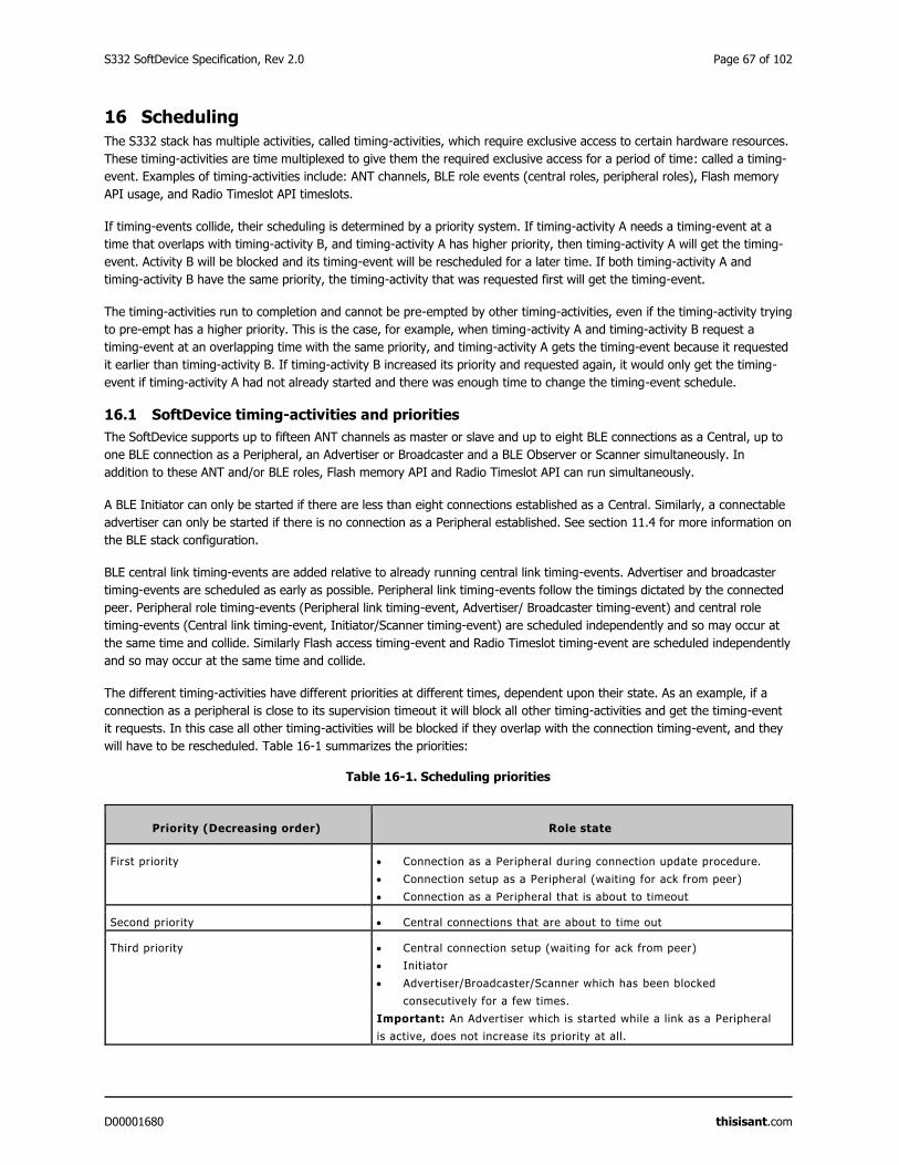
S332 SoftDevice Specification, Rev 2.0 Page 67 of 102
D00001680 thisisant.com
16 Scheduling
The S332 stack has multiple activities, called timing-activities, which require exclusive access to certain hardware resources.
These timing-activities are time multiplexed to give them the required exclusive access for a period of time: called a timing-
event. Examples of timing-activities include: ANT channels, BLE role events (central roles, peripheral roles), Flash memory
API usage, and Radio Timeslot API timeslots.
If timing-events collide, their scheduling is determined by a priority system. If timing-activity A needs a timing-event at a
time that overlaps with timing-activity B, and timing-activity A has higher priority, then timing-activity A will get the timing-
event. Activity B will be blocked and its timing-event will be rescheduled for a later time. If both timing-activity A and
timing-activity B have the same priority, the timing-activity that was requested first will get the timing-event.
The timing-activities run to completion and cannot be pre-empted by other timing-activities, even if the timing-activity trying
to pre-empt has a higher priority. This is the case, for example, when timing-activity A and timing-activity B request a
timing-event at an overlapping time with the same priority, and timing-activity A gets the timing-event because it requested
it earlier than timing-activity B. If timing-activity B increased its priority and requested again, it would only get the timing-
event if timing-activity A had not already started and there was enough time to change the timing-event schedule.
16.1 SoftDevice timing-activities and priorities
The SoftDevice supports up to fifteen ANT channels as master or slave and up to eight BLE connections as a Central, up to
one BLE connection as a Peripheral, an Advertiser or Broadcaster and a BLE Observer or Scanner simultaneously. In
addition to these ANT and/or BLE roles, Flash memory API and Radio Timeslot API can run simultaneously.
A BLE Initiator can only be started if there are less than eight connections established as a Central. Similarly, a connectable
advertiser can only be started if there is no connection as a Peripheral established. See section 11.4 for more information on
the BLE stack configuration.
BLE central link timing-events are added relative to already running central link timing-events. Advertiser and broadcaster
timing-events are scheduled as early as possible. Peripheral link timing-events follow the timings dictated by the connected
peer. Peripheral role timing-events (Peripheral link timing-event, Advertiser/ Broadcaster timing-event) and central role
timing-events (Central link timing-event, Initiator/Scanner timing-event) are scheduled independently and so may occur at
the same time and collide. Similarly Flash access timing-event and Radio Timeslot timing-event are scheduled independently
and so may occur at the same time and collide.
The different timing-activities have different priorities at different times, dependent upon their state. As an example, if a
connection as a peripheral is close to its supervision timeout it will block all other timing-activities and get the timing-event
it requests. In this case all other timing-activities will be blocked if they overlap with the connection timing-event, and they
will have to be rescheduled. Table 16-1 summarizes the priorities:
Table 16-1. Scheduling priorities
Priority (Decreasing order) Role state
First priority Connection as a Peripheral during connection update procedure.
Connection setup as a Peripheral (waiting for ack from peer)
Connection as a Peripheral that is about to timeout
Second priority Central connections that are about to time out
Third priority Central connection setup (waiting for ack from peer)
Initiator
Advertiser/Broadcaster/Scanner which has been blocked
consecutively for a few times.
Important: An Advertiser which is started while a link as a Peripheral
is active, does not increase its priority at all.
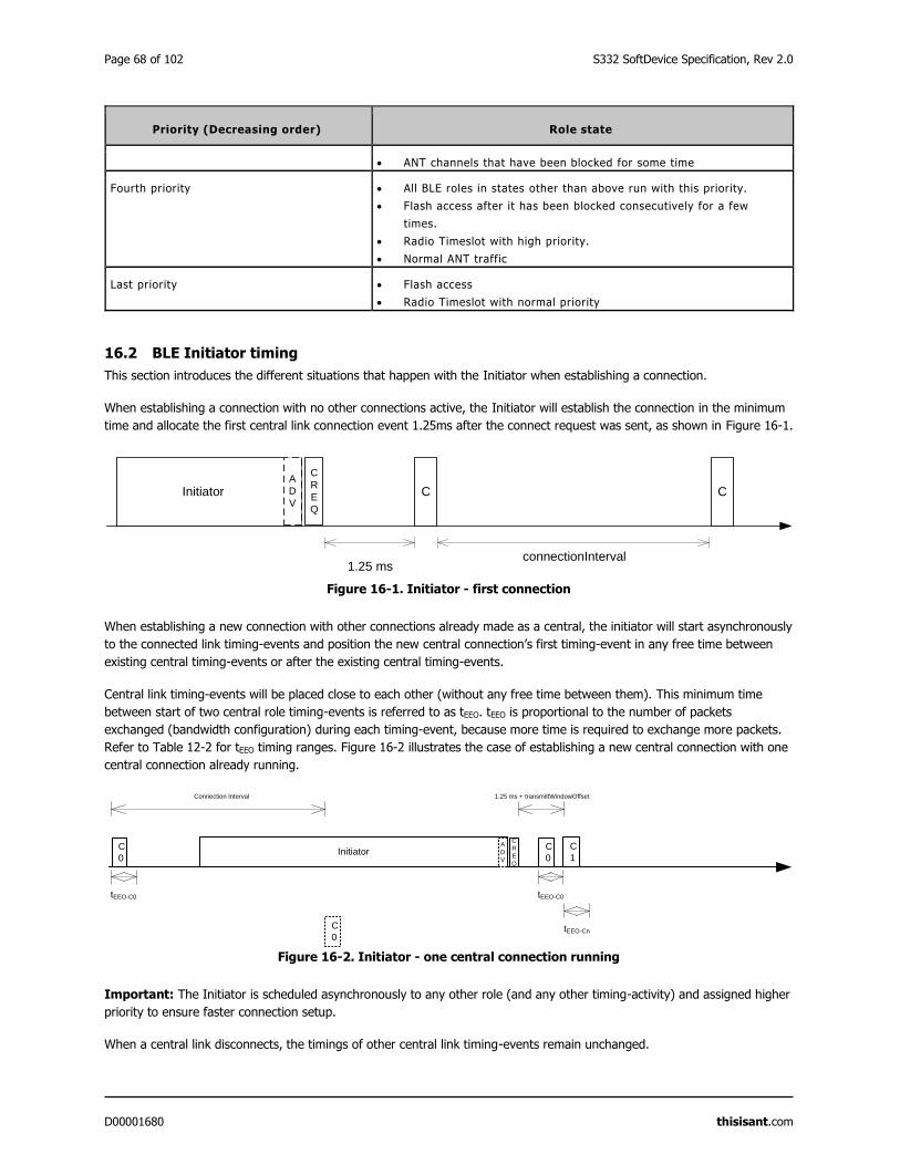
Page 68 of 102 S332 SoftDevice Specification, Rev 2.0
D00001680 thisisant.com
Priority (Decreasing order) Role state
ANT channels that have been blocked for some time
Fourth priority All BLE roles in states other than above run with this priority.
Flash access after it has been blocked consecutively for a few
times.
Radio Timeslot with high priority.
Normal ANT traffic
Last priority Flash access
Radio Timeslot with normal priority
16.2 BLE Initiator timing
This section introduces the different situations that happen with the Initiator when establishing a connection.
When establishing a connection with no other connections active, the Initiator will establish the connection in the minimum
time and allocate the first central link connection event 1.25ms after the connect request was sent, as shown in Figure 16-1.
Figure 16-1. Initiator - first connection
When establishing a new connection with other connections already made as a central, the initiator will start asynchronously
to the connected link timing-events and position the new central connection’s first timing-event in any free time between
existing central timing-events or after the existing central timing-events.
Central link timing-events will be placed close to each other (without any free time between them). This minimum time
between start of two central role timing-events is referred to as tEEO. tEEO is proportional to the number of packets
exchanged (bandwidth configuration) during each timing-event, because more time is required to exchange more packets.
Refer to Table 12-2 for tEEO timing ranges. Figure 16-2 illustrates the case of establishing a new central connection with one
central connection already running.
Figure 16-2. Initiator - one central connection running
Important: The Initiator is scheduled asynchronously to any other role (and any other timing-activity) and assigned higher
priority to ensure faster connection setup.
When a central link disconnects, the timings of other central link timing-events remain unchanged.
Initiator
1.25 ms
C
connectionInterval
CA
D
V
C
R
E
Q
tEEO-C0
InitiatorA
D
V
C
R
E
Q
1.25 ms + transmittWindowOffset
C
0
Connection Interval
C
0
C
1
tEEO-C0
C
0
tEEO-Cn
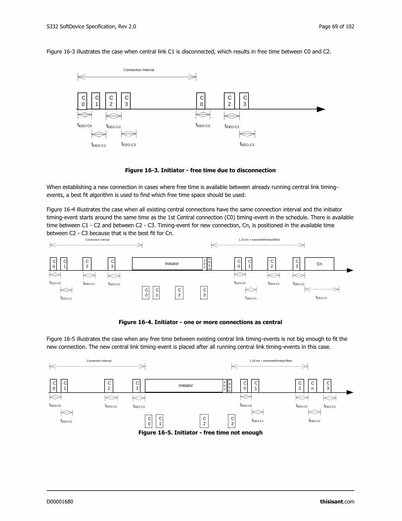
S332 SoftDevice Specification, Rev 2.0 Page 69 of 102
D00001680 thisisant.com
Figure 16-3 illustrates the case when central link C1 is disconnected, which results in free time between C0 and C2.
Figure 16-3. Initiator - free time due to disconnection
When establishing a new connection in cases where free time is available between already running central link timing-
events, a best fit algorithm is used to find which free time space should be used.
Figure 16-4 illustrates the case when all existing central connections have the same connection interval and the initiator
timing-event starts around the same time as the 1st Central connection (C0) timing-event in the schedule. There is available
time between C1 - C2 and between C2 - C3. Timing-event for new connection, Cn, is positioned in the available time
between C2 - C3 because that is the best fit for Cn.
Figure 16-4. Initiator - one or more connections as central
Figure 16-5 illustrates the case when any free time between existing central link timing-events is not big enough to fit the
new connection. The new central link timing-event is placed after all running central link timing-events in this case.
Figure 16-5. Initiator - free time not enough
C
1
tEEO-C0
C
3
C
0
C
2
tEEO-C1
tEEO-C2
tEEO-C3
Connection Interval
tEEO-C0
C
3
C
0
C
2
tEEO-C2
tEEO-C3
C
1
tEEO-C0
InitiatorA
D
V
C
R
E
Q
1.25 ms + transmittWindowOffset
C
3
C
0
C
2
tEEO-C1
tEEO-C2 tEEO-C3
Connection Interval
C
1
C
3
C
0
C
2
C
1
tEEO-C0
C
3
C
0
C
2
tEEO-C1
tEEO-C2 tEEO-C3
Cn
tEEO-Cn
C
1
tEEO-C0
InitiatorA
D
V
C
R
E
Q
1.25 ms + transmittWindowOffset
C
3
C
0
C
2
tEEO-C1
tEEO-C2 tEEO-C3
Connection Interval
C
1
C
3
C
0
C
2
C
1
tEEO-C0
C
3
C
0
C
2
tEEO-C2 tEEO-C3
C
n
tEEO-CntEEO-C1
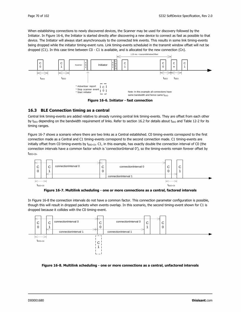
Page 70 of 102 S332 SoftDevice Specification, Rev 2.0
D00001680 thisisant.com
When establishing connections to newly discovered devices, the Scanner may be used for discovery followed by the
Initiator. In Figure 16-6, the Initiator is started directly after discovering a new device to connect as fast as possible to that
device. The Initiator will always start asynchronously to the connected link events. This results in some link timing-events
being dropped while the initiator timing-event runs. Link timing-events scheduled in the transmit window offset will not be
dropped (C1). In this case time between C0 - C1 is available, and is allocated for the new connection (Cn).
Figure 16-6. Initiator - fast connection
16.3 BLE Connection timing as a central
Central link timing-events are added relative to already running central link timing-events. They are offset from each other
by tEEO depending on the bandwidth requirement of links. Refer to section 16.2 for details about tEEO and Table 12-2 for its
timing ranges.
Figure 16-7 shows a scenario where there are two links as a Central established. C0 timing-events correspond to the first
connection made as a Central and C1 timing-events correspond to the second connection made. C1 timing-events are
initially offset from C0 timing-events by tEEO-C0. C1, in this example, has exactly double the connection interval of C0 (the
connection intervals have a common factor which is ‘connectionInterval 0’), so the timing-events remain forever offset by
tEEO-C0.
Figure 16-7. Multilink scheduling - one or more connections as a central, factored intervals
In Figure 16-8 the connection intervals do not have a common factor. This connection parameter configuration is possible,
though this will result in dropped packets when events overlap. In this scenario, the second timing-event shown for C1 is
dropped because it collides with the C0 timing-event.
Figure 16-8. Multilink scheduling - one or more connections as a central, unfactored intervals
C
0
C
1Initiator
C
0
C
n
tEEO
C
1
tEEO
A
D
V
C
R
E
Q
1.25 ms + transmittWindowOffset
C
0
C
1Scanner
A
D
V
tEEO
* Advertiser
* Stop scanner
* Start Note: In this example all connections have
same bandwidth and hence same tEEO
tEEO
C
0
tEEO-C0
C
1
C
0
connectionInterval 0 connectionInterval 0 C
0
tEEO-C0
C
1
connectionInterval 1
C
0
C
1
C
0
connectionInterval 0 C
0
C
1
C
1
connectionInterval 1 connectionInterval 1
connectionInterval 0
tEEO-C0
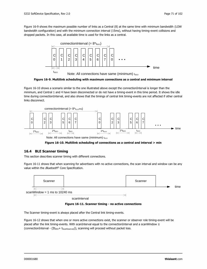
S332 SoftDevice Specification, Rev 2.0 Page 71 of 102
D00001680 thisisant.com
Figure 16-9 shows the maximum possible number of links as a Central (8) at the same time with minimum bandwidth (LOW
bandwidth configuration) and with the minimum connection interval (15ms), without having timing-event collisions and
dropped packets. In this case, all available time is used for the links as a central.
Figure 16-9. Multilink scheduling with maximum connections as a central and minimum interval
Figure 16-10 shows a scenario similar to the one illustrated above except the connectionInterval is longer than the
minimum, and Central 1 and 4 have been disconnected or do not have a timing-event in this time period. It shows the idle
time during connectionInterval, and also shows that the timings of central link timing-events are not affected if other central
links disconnect.
Figure 16-10. Multilink scheduling of connections as a central and interval > min
16.4 BLE Scanner timing
This section describes scanner timing with different connections.
Figure 16-11 shows that when scanning for advertisers with no active connections, the scan interval and window can be any
value within the Bluetooth® Core Specification.
Figure 16-11. Scanner timing - no active connections
The Scanner timing-event is always placed after the Central link timing-events.
Figure 16-12 shows that when one or more active connections exist, the scanner or observer role timing-event will be
placed after the link timing-events. With scanInterval equal to the connectionInterval and a scanWindow ≤
(connectionInterval - (ΣtEEO+ tScanReserved)), scanning will proceed without packet loss.
C
0
time
…C
0
connectionInterval (= 8*tEEO)
tEEO
C
1C
2
C
3
C
4
C
5
C
6
C
7
Note: All connections have same (minimum) tEEO
C
0
time
…
connectionInterval (> 8*tEEOms)
C
2
C
3
C
5
C
6
C
7
Note: All connections have same (minimum) tEEO
C
0
C
2
C
3
C
5
C
6
C
7
2*tEEO2*tEEO tEEO 2*tEEO
2*tEEO tEEO
Scanner
scanWindow = 1 ms to 10240 ms
time
scanInterval
Scanner
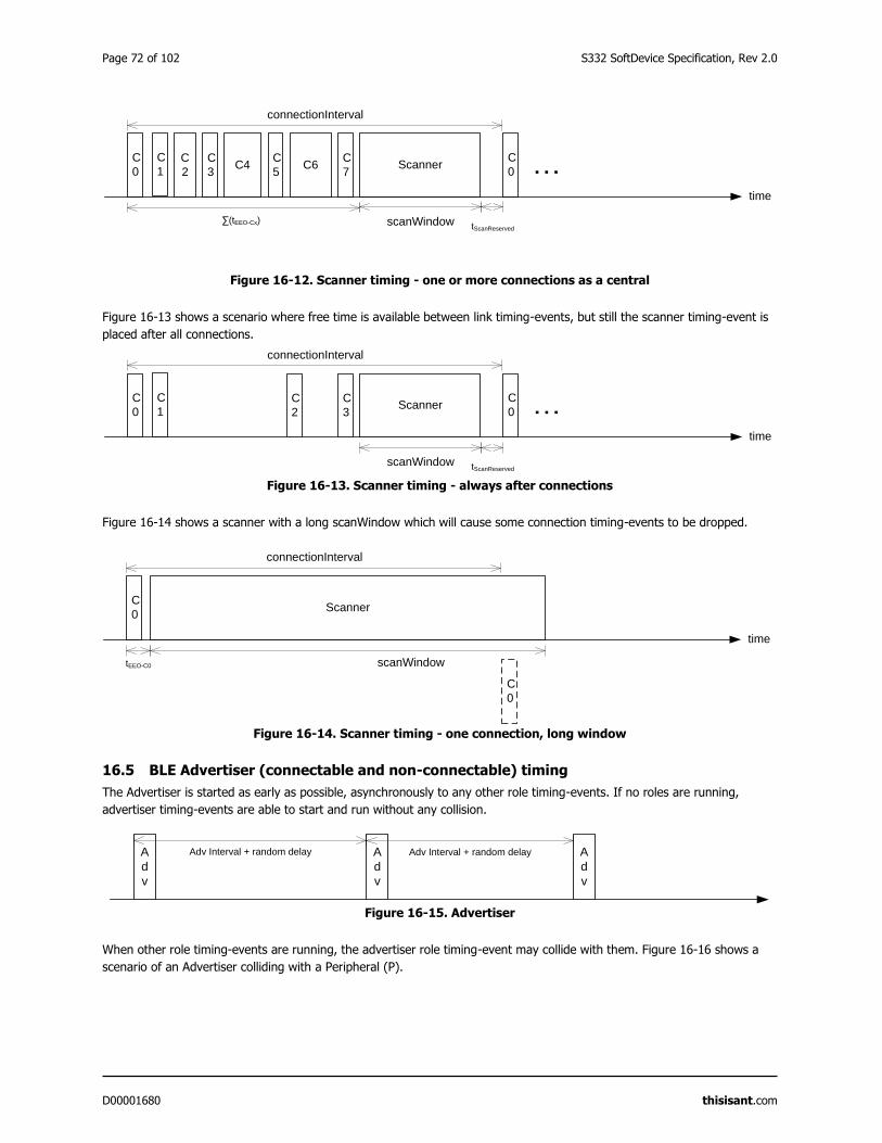
Page 72 of 102 S332 SoftDevice Specification, Rev 2.0
D00001680 thisisant.com
Figure 16-12. Scanner timing - one or more connections as a central
Figure 16-13 shows a scenario where free time is available between link timing-events, but still the scanner timing-event is
placed after all connections.
Figure 16-13. Scanner timing - always after connections
Figure 16-14 shows a scanner with a long scanWindow which will cause some connection timing-events to be dropped.
Figure 16-14. Scanner timing - one connection, long window
16.5 BLE Advertiser (connectable and non-connectable) timing
The Advertiser is started as early as possible, asynchronously to any other role timing-events. If no roles are running,
advertiser timing-events are able to start and run without any collision.
Figure 16-15. Advertiser
When other role timing-events are running, the advertiser role timing-event may collide with them. Figure 16-16 shows a
scenario of an Advertiser colliding with a Peripheral (P).
ScannerC
0
time
…
scanWindow
C
0
connectionInterval
∑(tEEO-Cx)tScanReserved
C
1C
7
C
2
C
3C4
C
5C6
ScannerC
0
time
…
scanWindow
C
0
connectionInterval
tScanReserved
C
1C
3
C
2
ScannerC
0
time
scanWindow
C
0
connectionInterval
tEEO-C0
A
d
v
A
d
v
Adv Interval + random delay A
d
v
Adv Interval + random delay
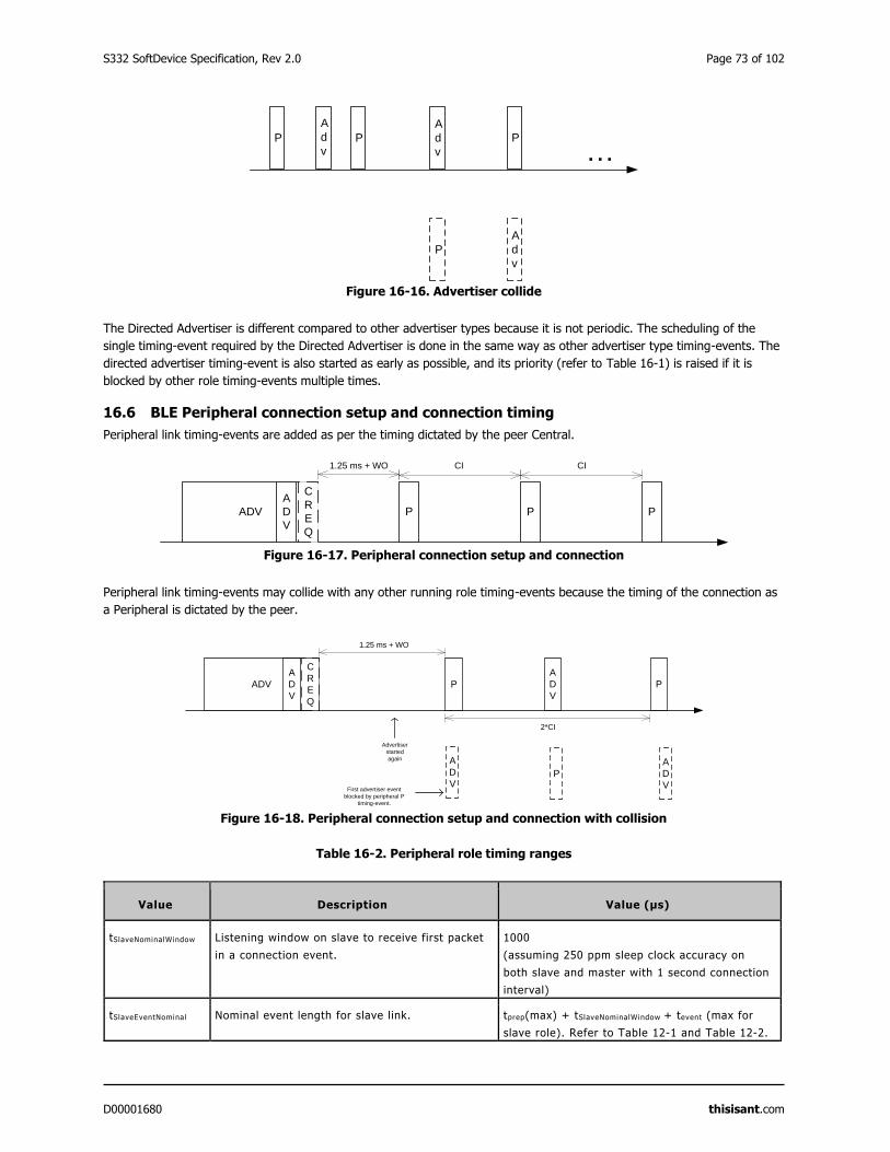
S332 SoftDevice Specification, Rev 2.0 Page 73 of 102
D00001680 thisisant.com
Figure 16-16. Advertiser collide
The Directed Advertiser is different compared to other advertiser types because it is not periodic. The scheduling of the
single timing-event required by the Directed Advertiser is done in the same way as other advertiser type timing-events. The
directed advertiser timing-event is also started as early as possible, and its priority (refer to Table 16-1) is raised if it is
blocked by other role timing-events multiple times.
16.6 BLE Peripheral connection setup and connection timing
Peripheral link timing-events are added as per the timing dictated by the peer Central.
Figure 16-17. Peripheral connection setup and connection
Peripheral link timing-events may collide with any other running role timing-events because the timing of the connection as
a Peripheral is dictated by the peer.
Figure 16-18. Peripheral connection setup and connection with collision
Table 16-2. Peripheral role timing ranges
Value Description Value (μs)
tSlaveNominalWindow Listening window on slave to receive first packet
in a connection event.
1000
(assuming 250 ppm sleep clock accuracy on
both slave and master with 1 second connection
interval)
tSlaveEventNominal Nominal event length for slave link. tprep(max) + tSlaveNominalWindow + tevent (max for
slave role). Refer to Table 12-1 and Table 12-2.
P P
A
d
v
P
A
d
v
P
…
A
d
v
ADV P
1.25 ms + WO
P
CI
C
R
E
Q
A
D
V
CI
P
P
A
D
V
ADV P
1.25 ms + WO
A
D
V
C
R
E
Q
A
D
V
2*CI
P
A
D
V
Advertiser
started
again
First advertiser event
blocked by peripheral P
timing-event.
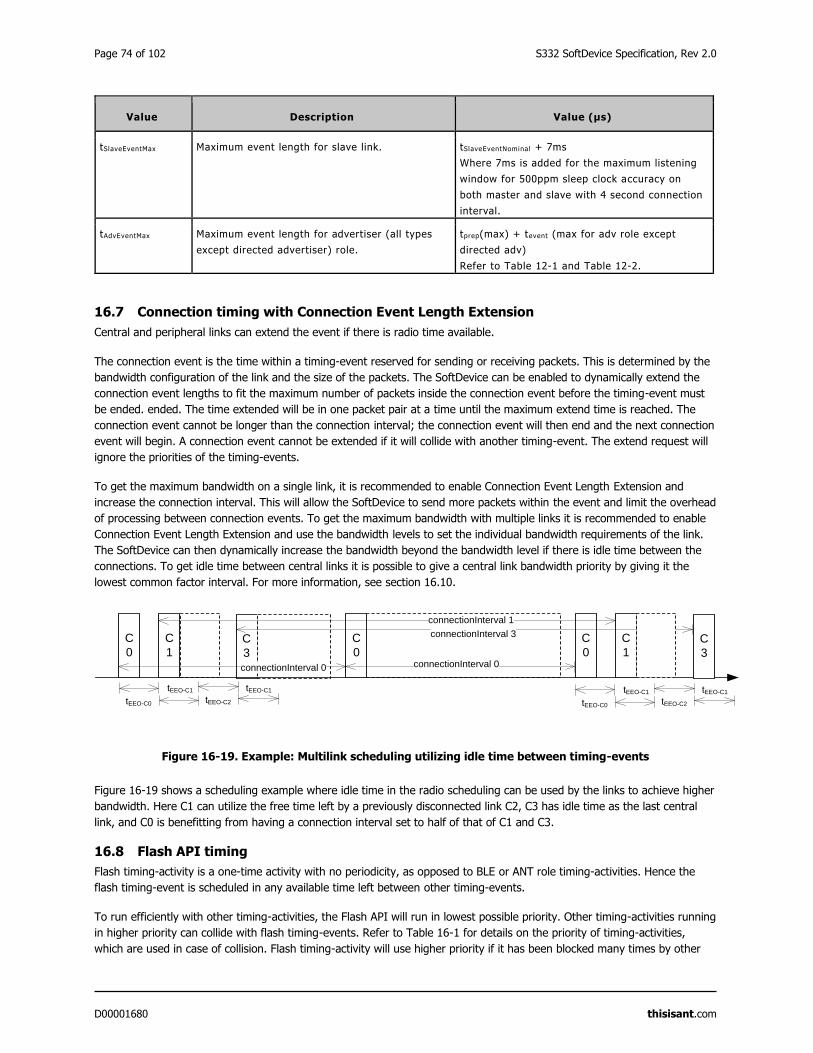
Page 74 of 102 S332 SoftDevice Specification, Rev 2.0
D00001680 thisisant.com
Value Description Value (μs)
tSlaveEventMax Maximum event length for slave link. tSlaveEventNominal + 7ms
Where 7ms is added for the maximum listening
window for 500ppm sleep clock accuracy on
both master and slave with 4 second connection
interval.
tAdvEventMax Maximum event length for advertiser (all types
except directed advertiser) role.
tprep(max) + tevent (max for adv role except
directed adv)
Refer to Table 12-1 and Table 12-2.
16.7 Connection timing with Connection Event Length Extension
Central and peripheral links can extend the event if there is radio time available.
The connection event is the time within a timing-event reserved for sending or receiving packets. This is determined by the
bandwidth configuration of the link and the size of the packets. The SoftDevice can be enabled to dynamically extend the
connection event lengths to fit the maximum number of packets inside the connection event before the timing-event must
be ended. ended. The time extended will be in one packet pair at a time until the maximum extend time is reached. The
connection event cannot be longer than the connection interval; the connection event will then end and the next connection
event will begin. A connection event cannot be extended if it will collide with another timing-event. The extend request will
ignore the priorities of the timing-events.
To get the maximum bandwidth on a single link, it is recommended to enable Connection Event Length Extension and
increase the connection interval. This will allow the SoftDevice to send more packets within the event and limit the overhead
of processing between connection events. To get the maximum bandwidth with multiple links it is recommended to enable
Connection Event Length Extension and use the bandwidth levels to set the individual bandwidth requirements of the link.
The SoftDevice can then dynamically increase the bandwidth beyond the bandwidth level if there is idle time between the
connections. To get idle time between central links it is possible to give a central link bandwidth priority by giving it the
lowest common factor interval. For more information, see section 16.10.
Figure 16-19. Example: Multilink scheduling utilizing idle time between timing-events
Figure 16-19 shows a scheduling example where idle time in the radio scheduling can be used by the links to achieve higher
bandwidth. Here C1 can utilize the free time left by a previously disconnected link C2, C3 has idle time as the last central
link, and C0 is benefitting from having a connection interval set to half of that of C1 and C3.
16.8 Flash API timing
Flash timing-activity is a one-time activity with no periodicity, as opposed to BLE or ANT role timing-activities. Hence the
flash timing-event is scheduled in any available time left between other timing-events.
To run efficiently with other timing-activities, the Flash API will run in lowest possible priority. Other timing-activities running
in higher priority can collide with flash timing-events. Refer to Table 16-1 for details on the priority of timing-activities,
which are used in case of collision. Flash timing-activity will use higher priority if it has been blocked many times by other
C
3
C
0
tEEO-C0
C
1
C
0
connectionInterval 0 connectionInterval 0
C
0
C
1
connectionInterval 1
C
3
tEEO-C1
tEEO-C2
tEEO-C1
tEEO-C0
tEEO-C1
tEEO-C2
tEEO-C1
connectionInterval 3

S332 SoftDevice Specification, Rev 2.0 Page 75 of 102
D00001680 thisisant.com
timing-activities. Flash timing-activity may not get timing-event at all if other timing-events occupy most of the time and use
priority higher than flash timing-activity. To avoid waiting long while using the Flash API, flash timing-activity will fail in the
case where it cannot get a timing-event before a timeout.
16.9 Timeslot API timing
Radio Timeslot API timing-activity is scheduled independently of any other timing activity, hence it can collide with any
other timing-activity in the SoftDevice.
Refer to Table 16-1 for details on the priority of timing-activities, which are used in case of collision. If the requested timing-
event collides with already scheduled timing-events with equal or higher priority, the request will be denied (blocked). If a
later arriving timing-activity of higher priority causes a collision, the request will be cancelled. However, a timing-event that
has already started cannot be interrupted or cancelled.
If the timeslot is requested as earliest possible, the Timeslot timing-event is scheduled in any available free time. Hence
there is less probability of collision with earliest possible request. The Timeslot API timing-activity has two configurable
priorities. To run efficiently with other timing-activities, the Timeslot API should run in lowest possible priority. It can be
configured to use higher priority if it has been blocked many times by other timing-activities and is in a critical state.
16.10 BLE suggested intervals and windows
The time required to fit one timing-event of all active central links is equal to the sum of tEEO of all active central links.
Therefore eight link timing-events can complete in maximum ΣtEEO-Cx, which is around 15ms for LOW bandwidth
configuration Refer Table 12-1 and Table 12-2 for timing ranges in central role.
Note that this does not leave sufficient time in the schedule for scanning or initiating new connections (when the number of
connections already established is less than eight). Scanner, Observer, and Initiator events can therefore cause connection
packets to be dropped.
It is recommended that all connections have intervals that have a common factor. This common factor should be greater or
equal to ΣtEEO-Cx. Note that this sum depends on the number of connections and their respective bandwidth. In the case of
eight connections with LOW bandwidth it is 15ms, for 3 connections with MID bandwidth it is 11.25ms. When15ms is
usedas the common factor, all connections would have an interval of 15ms or a multiple of 15ms, e.g. 30ms, 45ms, etc.
If short connection intervals are not essential to the application and there is a need to have a Scanner running at the same
time as connections, then it is possible to avoid dropping packets on any connection as a Central by having a connection
interval larger than ΣtEEO-Cx plus the scanWindow plus tScanReserved. Note that the Initiator is scheduled asynchronously to any
other role (and any other timing-activity), hence initiator timing-events might collide with other timing-events even if the
above recommendation is followed.
As an example, setting the connection interval to 43.75ms will allow three connection events with MID bandwidth and a
scan window of 31.0ms, which is sufficient to ensure advertising packets from a 20ms (nominal) advertiser hitting and being
responded to within the window.
To summarize, a recommended configuration for operation without dropped packets for cases of only central roles running
is:
All central role intervals (i.e. connection interval, scanner/observer/initiator intervals) should have a common
factor. This common factor should be ≥ ΣtEEO-Cx + scanWindow + tScanReserved.
Peripheral roles use the same time space as all other roles (including any other peripheral and central roles), hence a
collision free schedule cannot be guaranteed if a peripheral role is running along with any other role. The probability of
collision can be reduced (though not eliminated) if the central role link parameters are set as suggested in this section, and
the following rules are applied for all roles:
Interval of all roles have a common factor which is ≥ ΣtEEO-Cx + (tScanReserved + ScanWindow) + tSlaveEventNominal +
tAdvEventMax
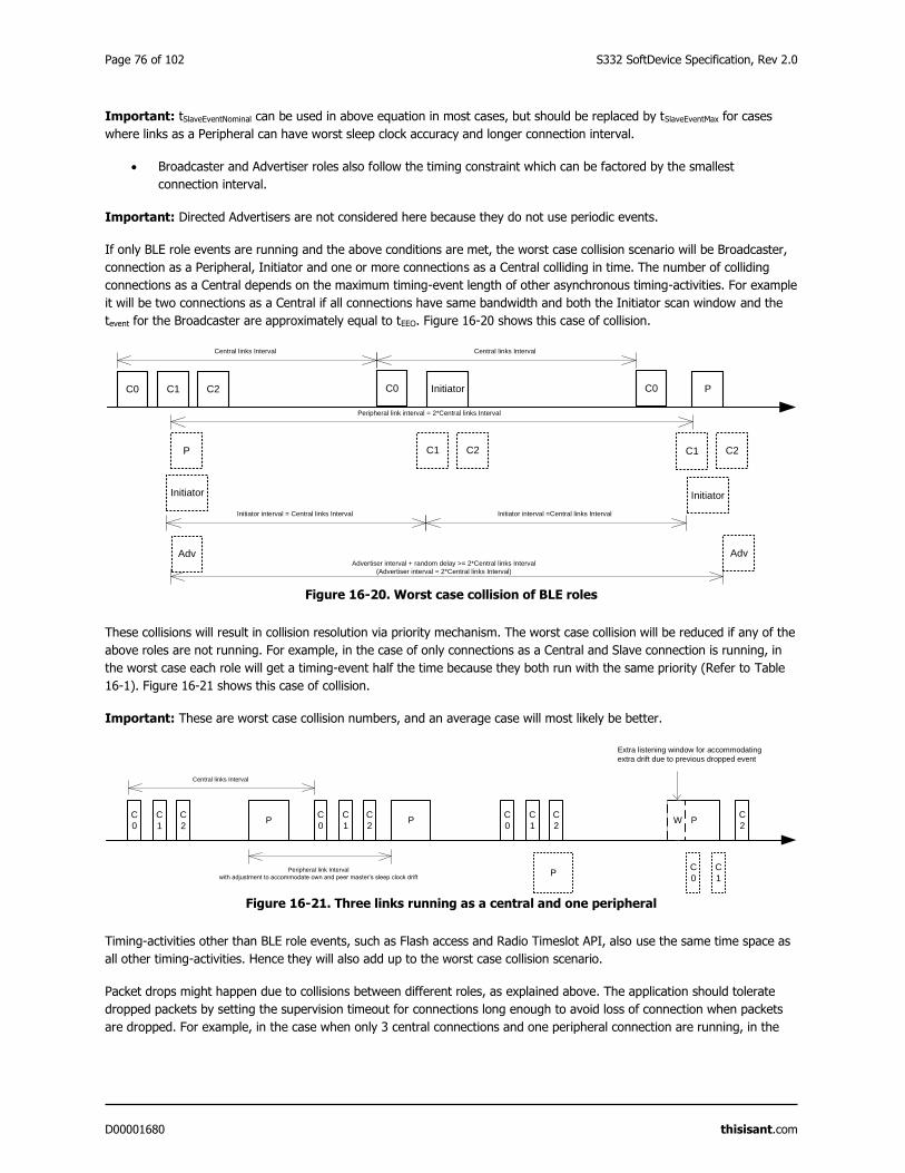
Page 76 of 102 S332 SoftDevice Specification, Rev 2.0
D00001680 thisisant.com
Important: tSlaveEventNominal can be used in above equation in most cases, but should be replaced by tSlaveEventMax for cases
where links as a Peripheral can have worst sleep clock accuracy and longer connection interval.
Broadcaster and Advertiser roles also follow the timing constraint which can be factored by the smallest
connection interval.
Important: Directed Advertisers are not considered here because they do not use periodic events.
If only BLE role events are running and the above conditions are met, the worst case collision scenario will be Broadcaster,
connection as a Peripheral, Initiator and one or more connections as a Central colliding in time. The number of colliding
connections as a Central depends on the maximum timing-event length of other asynchronous timing-activities. For example
it will be two connections as a Central if all connections have same bandwidth and both the Initiator scan window and the
tevent for the Broadcaster are approximately equal to tEEO. Figure 16-20 shows this case of collision.
Figure 16-20. Worst case collision of BLE roles
These collisions will result in collision resolution via priority mechanism. The worst case collision will be reduced if any of the
above roles are not running. For example, in the case of only connections as a Central and Slave connection is running, in
the worst case each role will get a timing-event half the time because they both run with the same priority (Refer to Table
16-1). Figure 16-21 shows this case of collision.
Important: These are worst case collision numbers, and an average case will most likely be better.
Figure 16-21. Three links running as a central and one peripheral
Timing-activities other than BLE role events, such as Flash access and Radio Timeslot API, also use the same time space as
all other timing-activities. Hence they will also add up to the worst case collision scenario.
Packet drops might happen due to collisions between different roles, as explained above. The application should tolerate
dropped packets by setting the supervision timeout for connections long enough to avoid loss of connection when packets
are dropped. For example, in the case when only 3 central connections and one peripheral connection are running, in the
C0
Central links Interval
C1 C2 C0
C1 C2P
Initiator
Adv
C0
C1 C2
Central links Interval
Initiator P
Initiator
Adv
Peripheral link interval = 2*Central links Interval
Advertiser interval + random delay >= 2*Central links Interval
(Advertiser interval = 2*Central links Interval)
Initiator interval = Central links Interval Initiator interval =Central links Interval
C
0
C
1
C
2
C
0
C
1
C
2
C
0
C
1
C
2P
Central links Interval
C
0
C
1
C
2P
P
P
Peripheral link Interval
with adjustment to accommodate own and peer master’s sleep clock drift
W
Extra listening window for accommodating
extra drift due to previous dropped event

S332 SoftDevice Specification, Rev 2.0 Page 77 of 102
D00001680 thisisant.com
worst case each role will get a timing-event half the time. To accommodate this packet drop, the application should set the
supervision timeout to twice the size it would have set if only either a Central or Peripheral role was running.
Page 78 of 102 S332 SoftDevice Specification, Rev 2.0
D00001680 thisisant.com
17 Interrupt model and processor availability
This section documents the SoftDevice interrupt model, how interrupts are forwarded to the application, and describes how
long the processor is used by the SoftDevice in different priority levels.
17.1 Exception model
As the SoftDevice, including the Master Boot Record (MBR), needs to handle some interrupts, all interrupts are routed
through the MBR and SoftDevice. The ones that should be handled by the application are forwarded and the rest are
handled within the SoftDevice itself. This section describes the interrupt forwarding mechanism.
For more information on the MBR, see section 13.1.
17.1.1 Interrupt forwarding to the application
The forwarding of interrupts to the application depends on the state of the SoftDevice.
At the lowest level, the MBR receives all interrupts and forwards them to the SoftDevice regardless of whether the
SoftDevice is enabled or not. The use of a bootloader introduces some exceptions to this: see section 13.
Some peripherals and their respective interrupt numbers are reserved for use by the SoftDevice (section 7.1). Any interrupt
handler defined by the application for these interrupts will not be called as long as the SoftDevice is enabled. When the
SoftDevice is disabled, these interrupts will be forwarded to the application.
The SVC interrupt is always intercepted by the SoftDevice regardless of whether it is enabled or disabled. The SoftDevice
inspects the SVC number, and if it is equal or greater than 0x10, the interrupt is processed by the SoftDevice. SVC numbers
below 0x10 are forwarded to the application's SVC interrupt handler. This allows the application to make use of a range of
SVC numbers for its own purpose, for example, for an RTOS.
Interrupts not used by the SoftDevice are always forwarded to the application.
For the SoftDevice to locate the application interrupt vectors, the application must define its interrupt vector table at the
bottom of the Application Flash Region illustrated in Figure 15-1. When the base address of the application code is directly
after the top address of the SoftDevice, the code can be developed as a standard ARM® Cortex® -M4 application project
with the compiler creating the interrupt vector table.
17.1.2 Interrupt latency due to System on Chip (SoC) framework
Latency, additional to ARM® Cortex® -M4 hardware architecture latency, is introduced by SoftDevice logic to manage
interrupt events.
This latency occurs when an interrupt is forwarded to the application from the SoftDevice and is part of the minimum
latency for each application interrupt. This is the latency added by the interrupt forwarding latency alone. The maximum
application interrupt latency is dependent on SoftDevice activity, as described in section 17.3.
Table 17-1. Additional latency due to SoftDevice and MBR forwarding interrupts
Interrupt SoftDevice enabled SoftDevice disabled
Open peripheral interrupt < 2 μs < 1 μs
Blocked or restricted peripheral
interrupt (only forwarded when
SoftDevice disabled)
N/A < 2 μs
Application SVC interrupt < 2 μs < 2 μs
S332 SoftDevice Specification, Rev 2.0 Page 79 of 102
D00001680 thisisant.com
17.2 Interrupt priority levels
This section gives an overview of interrupt levels used by the SoftDevice, and the interrupt levels that are available for the
application.
To implement the SoftDevice API as SuperVisor Calls (SVCs, see section 4) and ensure that embedded protocol real-time
requirements are met independently of the application processing, the SoftDevice implements an interrupt model where
application interrupts and SoftDevice interrupts are interleaved. This model will result in application interrupts being
postponed or pre-empted, leading to longer perceived application interrupt latency and interrupt execution times.
The application must take care to select the correct interrupt priorities for application events according to the guidelines that
follow. The NVIC API to the SoC Library supports safe configuration of interrupt priorities from the application.
The ARM® Cortex® -M4 processor has eight configurable interrupt priorities ranging from 0 to 7 (with 0 being highest
priority). On reset, all interrupts are configured with the highest priority (0).
The SoftDevice reserves and uses the following priority levels, which must remain unused by the application programmer:
Level 0 is used for the SoftDevice's timing critical processing.
Level 1 is used for handling the memory isolation and run time protection (section 5.4).
Level 4 is used by higher level deferrable tasks and the API functions executed as SVC interrupts.
Level 5 is reserved for future use.
The application can use the remaining interrupt priority levels, in addition to the main, or thread, context.
As seen from Figure 17-1, the application has available priority level 2 and 3, located between the higher and lower priority
levels reserved by the SoftDevice. This enables a low-latency application interrupt to support fast sensor interfaces. An
application interrupt at priority level 2 or 3 will only experience latency from SoftDevice interrupts at priority levels 0 and 1,
while application interrupts at priority levels 6 or 7 can experience latency from all SoftDevice priority levels.
Important: The priorities of the interrupts reserved by the SoftDevice cannot be changed. This includes the SVC interrupt.
Handlers running at a priority level higher than 4 (lower numerical priority value) have neither access to SoftDevice
functions nor to application specific SVCs or RTOS functions running at lower priority levels (higher numerical priority
values).
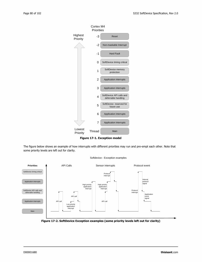
Page 80 of 102 S332 SoftDevice Specification, Rev 2.0
D00001680 thisisant.com
Figure 17-1. Exception model
The figure below shows an example of how interrupts with different priorities may run and pre-empt each other. Note that
some priority levels are left out for clarity.
Figure 17-2. SoftDevice Exception examples (some priority levels left out for clarity)
Lowest
Priority
Highest
PriorityReset
Non-maskable Interrupt
Hard Fault
Cortex M4
Priorities
-3
-2
-1
0
1
2
3
4
SoftDevice memory
protection
Application interrupts
Application interrupts
SoftDevice API calls and
deferrable handling
SoftDevice timing critical
5
6
7
SoftDevice reserved for
future use
Application interrupts
Application interrupts
MainThread
API call
Softdevice - Exception examples
Priorities
Application interrupts
SoftDevice API calls and
deferrable handling
Application interrupts
Main
SoftDevice timing critical
Low priority
application
interrupt
API call
High priority
application
interrupt
API call
Protocol
interrupt
Protocol
interrupt
Internal
protocol
signal
Application
event
signal
High priority
application
interrupt
API Calls Sensor interrupts Protocol event
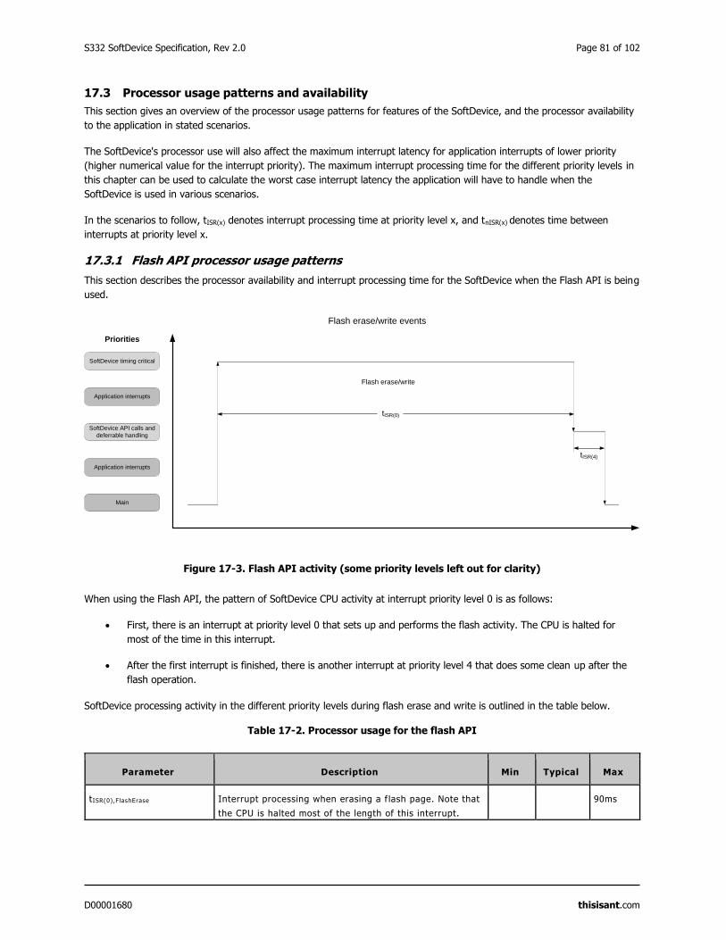
S332 SoftDevice Specification, Rev 2.0 Page 81 of 102
D00001680 thisisant.com
17.3 Processor usage patterns and availability
This section gives an overview of the processor usage patterns for features of the SoftDevice, and the processor availability
to the application in stated scenarios.
The SoftDevice's processor use will also affect the maximum interrupt latency for application interrupts of lower priority
(higher numerical value for the interrupt priority). The maximum interrupt processing time for the different priority levels in
this chapter can be used to calculate the worst case interrupt latency the application will have to handle when the
SoftDevice is used in various scenarios.
In the scenarios to follow, tISR(x) denotes interrupt processing time at priority level x, and tnISR(x) denotes time between
interrupts at priority level x.
17.3.1 Flash API processor usage patterns
This section describes the processor availability and interrupt processing time for the SoftDevice when the Flash API is being
used.
Figure 17-3. Flash API activity (some priority levels left out for clarity)
When using the Flash API, the pattern of SoftDevice CPU activity at interrupt priority level 0 is as follows:
First, there is an interrupt at priority level 0 that sets up and performs the flash activity. The CPU is halted for
most of the time in this interrupt.
After the first interrupt is finished, there is another interrupt at priority level 4 that does some clean up after the
flash operation.
SoftDevice processing activity in the different priority levels during flash erase and write is outlined in the table below.
Table 17-2. Processor usage for the flash API
Parameter Description Min Typical Max
tISR(0),FlashErase Interrupt processing when erasing a f lash page. Note that
the CPU is halted most of the length of this interrupt.
90ms
tISR(0)
Flash erase/write events
Flash erase/write
Priorities
Application interrupts
SoftDevice API calls and
deferrable handling
Application interrupts
Main
SoftDevice timing critical
tISR(4)
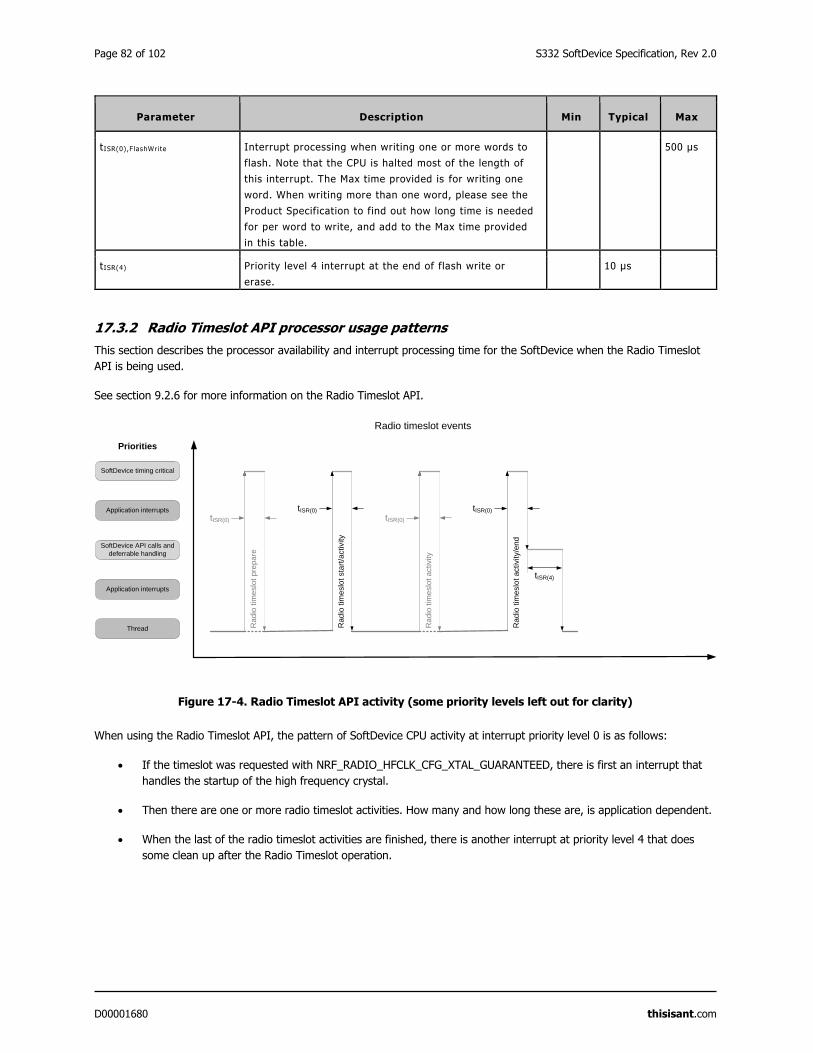
Page 82 of 102 S332 SoftDevice Specification, Rev 2.0
D00001680 thisisant.com
Parameter Description Min Typical Max
tISR(0),FlashWrite Interrupt processing when writing one or more words to
flash. Note that the CPU is halted most of the length of
this interrupt. The Max time provided is for writing one
word. When writing more than one word, please see the
Product Specification to find out how long time is needed
for per word to write, and add to the Max time provided
in this table.
500 μs
tISR(4) Priority level 4 interrupt at the end of flash write or
erase.
10 μs
17.3.2 Radio Timeslot API processor usage patterns
This section describes the processor availability and interrupt processing time for the SoftDevice when the Radio Timeslot
API is being used.
See section 9.2.6 for more information on the Radio Timeslot API.
Figure 17-4. Radio Timeslot API activity (some priority levels left out for clarity)
When using the Radio Timeslot API, the pattern of SoftDevice CPU activity at interrupt priority level 0 is as follows:
If the timeslot was requested with NRF_RADIO_HFCLK_CFG_XTAL_GUARANTEED, there is first an interrupt that
handles the startup of the high frequency crystal.
Then there are one or more radio timeslot activities. How many and how long these are, is application dependent.
When the last of the radio timeslot activities are finished, there is another interrupt at priority level 4 that does
some clean up after the Radio Timeslot operation.
tISR(0)
Radio timeslot events
Ra
dio
tim
eslo
t pre
pa
re
Priorities
Application interrupts
SoftDevice API calls and
deferrable handling
Application interrupts
Thread
SoftDevice timing critical
tISR(0)
Rad
io tim
eslo
t sta
rt/a
ctivity
tISR(0)
Ra
dio
tim
eslo
t activity
tISR(0)R
ad
io t
ime
slo
t activity/e
nd
tISR(4)
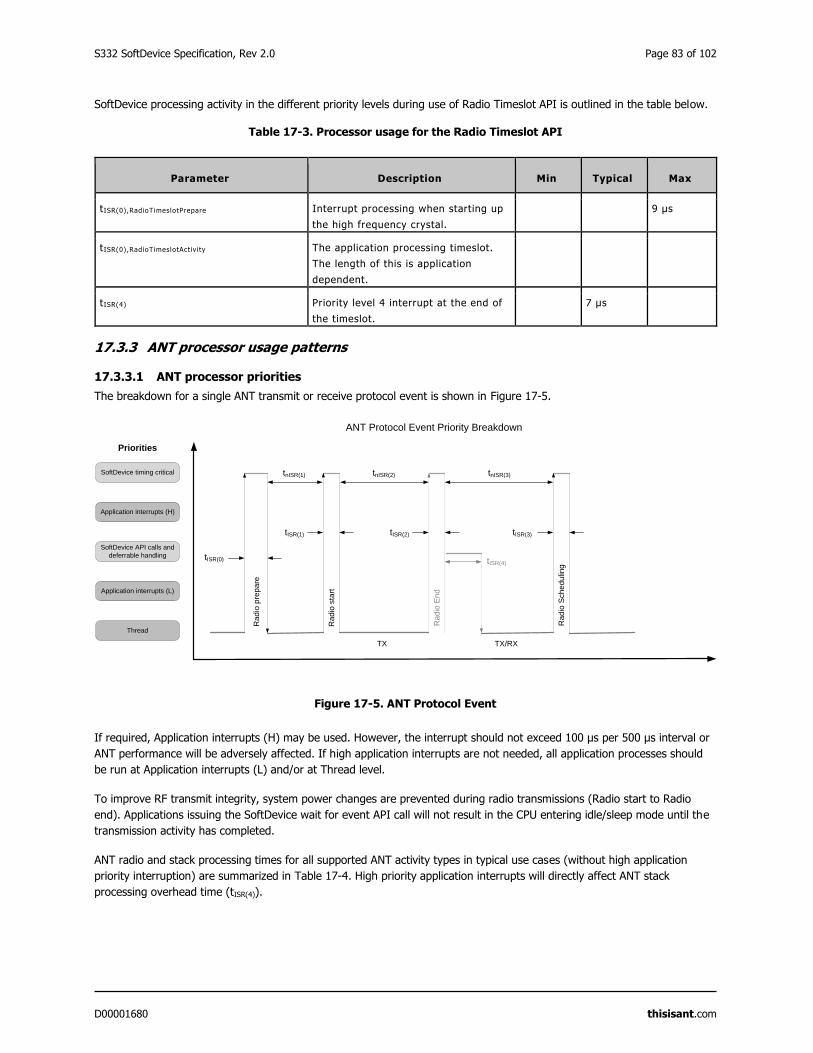
S332 SoftDevice Specification, Rev 2.0 Page 83 of 102
D00001680 thisisant.com
SoftDevice processing activity in the different priority levels during use of Radio Timeslot API is outlined in the table below.
Table 17-3. Processor usage for the Radio Timeslot API
Parameter Description Min Typical Max
tISR(0),RadioTimeslotPrepare Interrupt processing when starting up
the high frequency crystal.
9 μs
tISR(0),RadioTimeslotActiv i ty The application processing timeslot.
The length of this is application
dependent.
tISR(4) Priority level 4 interrupt at the end of
the timeslot.
7 μs
17.3.3 ANT processor usage patterns
17.3.3.1 ANT processor priorities
The breakdown for a single ANT transmit or receive protocol event is shown in Figure 17-5.
Figure 17-5. ANT Protocol Event
If required, Application interrupts (H) may be used. However, the interrupt should not exceed 100 μs per 500 μs interval or
ANT performance will be adversely affected. If high application interrupts are not needed, all application processes should
be run at Application interrupts (L) and/or at Thread level.
To improve RF transmit integrity, system power changes are prevented during radio transmissions (Radio start to Radio
end). Applications issuing the SoftDevice wait for event API call will not result in the CPU entering idle/sleep mode until the
transmission activity has completed.
ANT radio and stack processing times for all supported ANT activity types in typical use cases (without high application
priority interruption) are summarized in Table 17-4. High priority application interrupts will directly affect ANT stack
processing overhead time (tISR(4)).
tnISR(1)
tISR(0)
Ra
dio
sta
rt
ANT Protocol Event Priority Breakdown
Ra
dio
pre
pa
re
tnISR(2)
Ra
dio
Sch
edu
lingtISR(4)
Ra
dio
En
d
tnISR(3)
TX TX/RX
tISR(1) tISR(2) tISR(3)
Priorities
Application interrupts (H)
SoftDevice API calls and
deferrable handling
Application interrupts (L)
Thread
SoftDevice timing critical
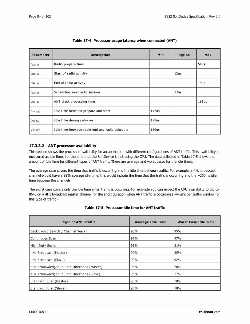
Page 84 of 102 S332 SoftDevice Specification, Rev 2.0
D00001680 thisisant.com
Table 17-4. Processor usage latency when connected (ANT)
Parameter Description Min Typical Max
tISR(0) Radio prepare time 58us
tISR(1) Start of radio activity 12us
tISR(2) End of radio activity 19us
tISR(3) Scheduling next radio session 37us
tISR(4) ANT stack processing time 168us
tnISR(1) Idle time between prepare and start 117us
tnISR(2) Idle time during radio on 173us
tnISR(3) Idle time between radio end and radio schedule 129us
17.3.3.2 ANT processor availability
This section shows the processor availability for an application with different configurations of ANT traffic. This availability is
measured as idle time, i.e. the time that the SoftDevice is not using the CPU. The data collected in Table 17-5 shows the
amount of idle time for different types of ANT traffic. There are average and worst cases for the idle times.
The average case covers the time that traffic is occurring and the idle time between traffic. For example, a 4Hz broadcast
channel would have a 99% average idle time, this would include the time that the traffic is occurring and the ~250ms idle
time between the channels.
The worst case covers only the idle time when traffic is occurring. For example you can expect the CPU availability to dip to
86% on a 4Hz broadcast master channel for the short duration when ANT traffic is occurring (~4-5ms per traffic window for
this type of traffic).
Table 17-5. Processor idle time for ANT traffic
Type of ANT Traffic Average Idle Time Worst Case Idle Time
Background Search / Channel Search 98% 95%
Continuous Scan 97% 97%
High Duty Search 95% 51%
4Hz Broadcast (Master) 99% 85%
4Hz Broadcast (Slave) 99% 92%
4Hz Acknowledged in Both Directions (Master) 95% 78%
4Hz Acknowledged in Both Directions (Slave) 95% 77%
Standard Burst (Master) 90% 78%
Standard Burst (Slave) 90% 78%
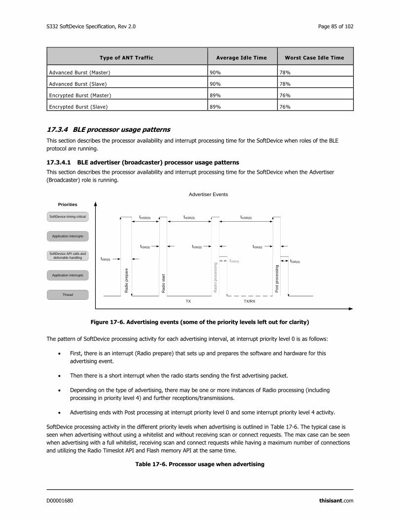
S332 SoftDevice Specification, Rev 2.0 Page 85 of 102
D00001680 thisisant.com
Type of ANT Traffic Average Idle Time Worst Case Idle Time
Advanced Burst (Master) 90% 78%
Advanced Burst (Slave) 90% 78%
Encrypted Burst (Master) 89% 76%
Encrypted Burst (Slave) 89% 76%
17.3.4 BLE processor usage patterns
This section describes the processor availability and interrupt processing time for the SoftDevice when roles of the BLE
protocol are running.
17.3.4.1 BLE advertiser (broadcaster) processor usage patterns
This section describes the processor availability and interrupt processing time for the SoftDevice when the Advertiser
(Broadcaster) role is running.
Figure 17-6. Advertising events (some of the priority levels left out for clarity)
The pattern of SoftDevice processing activity for each advertising interval, at interrupt priority level 0 is as follows:
First, there is an interrupt (Radio prepare) that sets up and prepares the software and hardware for this
advertising event.
Then there is a short interrupt when the radio starts sending the first advertising packet.
Depending on the type of advertising, there may be one or more instances of Radio processing (including
processing in priority level 4) and further receptions/transmissions.
Advertising ends with Post processing at interrupt priority level 0 and some interrupt priority level 4 activity.
SoftDevice processing activity in the different priority levels when advertising is outlined in Table 17-6. The typical case is
seen when advertising without using a whitelist and without receiving scan or connect requests. The max case can be seen
when advertising with a full whitelist, receiving scan and connect requests while having a maximum number of connections
and utilizing the Radio Timeslot API and Flash memory API at the same time.
Table 17-6. Processor usage when advertising
tnISR(0)
tISR(0)
Rad
io s
tart
Advertiser Events
Rad
io p
rep
are
tISR(4)
tnISR(0)
Post
pro
cessin
g
tISR(4)
Rad
io p
rocessin
gtnISR(0)
TX TX/RX
tISR(0) tISR(0) tISR(0)
Priorities
Application interrupts
SoftDevice API calls and
deferrable handling
Application interrupts
Thread
SoftDevice timing critical
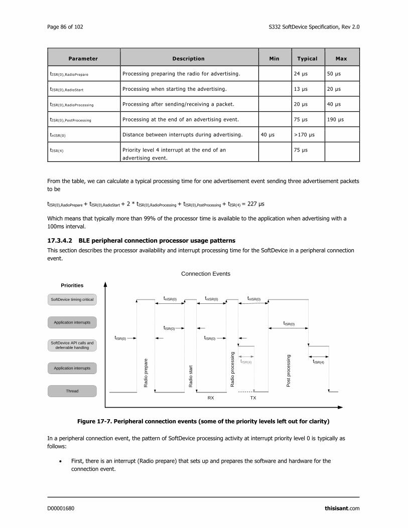
Page 86 of 102 S332 SoftDevice Specification, Rev 2.0
D00001680 thisisant.com
Parameter Description Min Typical Max
tISR(0),RadioPrepare Processing preparing the radio for advertising. 24 μs 50 μs
tISR(0),RadioStart Processing when starting the advertising. 13 μs 20 μs
tISR(0),RadioProcessing Processing after sending/receiving a packet. 20 μs 40 μs
tISR(0),PostProcessing Processing at the end of an advertising event. 75 μs 190 μs
tnISR(0) Distance between interrupts during advertising. 40 μs >170 μs
tISR(4) Priority level 4 interrupt at the end of an
advertising event.
75 μs
From the table, we can calculate a typical processing time for one advertisement event sending three advertisement packets
to be
tISR(0),RadioPrepare + tISR(0),RadioStart + 2 * tISR(0),RadioProcessing + tISR(0),PostProcessing + tISR(4) = 227 μs
Which means that typically more than 99% of the processor time is available to the application when advertising with a
100ms interval.
17.3.4.2 BLE peripheral connection processor usage patterns
This section describes the processor availability and interrupt processing time for the SoftDevice in a peripheral connection
event.
Figure 17-7. Peripheral connection events (some of the priority levels left out for clarity)
In a peripheral connection event, the pattern of SoftDevice processing activity at interrupt priority level 0 is typically as
follows:
First, there is an interrupt (Radio prepare) that sets up and prepares the software and hardware for the
connection event.
tnISR(0)
tISR(0)
tISR(0)
tISR(4)
Connection Events
Rad
io p
rep
are
tnISR(0)
tISR(0)
Rad
io s
tart
tnISR(0)
tISR(0)
Rad
io p
roce
ssin
g
Post
pro
cessin
g
RX TX
Priorities
Application interrupts
SoftDevice API calls and
deferrable handling
Application interrupts
Thread
SoftDevice timing critical
tISR(4)
S332 SoftDevice Specification, Rev 2.0 Page 87 of 102
D00001680 thisisant.com
Then there is a short interrupt when the radio starts listening for the first packet.
When the reception is finished, there is Radio processing that processes the received packet and switches the
radio to transmission.
When the transmission is finished, there is either a Radio processing including a switch back to reception and
possibly a new transmission after that, or the event ends with post processing.
After the radio and post processing in priority level 0, the SoftDevice processes any received data packets,
executes any GATT, ATT or SMP operations and generates events to the application as required in priority level 4.
The interrupt at this priority level is therefore highly variable based on the stack operations executed.
SoftDevice processing activity in the different priority levels during peripheral connection events is outlined in Table 17-7.
The typical case is seen when sending GATT write commands writing 20 bytes. The max case can be seen when sending
and receiving maximum length packets and at the same time initiating encryption, while having a maximum number of
connections and utilizing the Radio Timeslot API and Flash memory API at the same time.
Table 17-7. Processor usage when connected
Parameter Description Min Typical Max
tISR(0),RadioPrepare Processing preparing the radio for a connection event. 35 μs 50 μs
tISR(0),RadioStart Processing when starting the connection event. 15 μs 20 μs
tISR(0),RadioProcessing Processing after sending or receiving a packet. 30 μs 40 μs
tISR(0),PostProcessing Processing at the end of a connection event. 90 μs 231 μs
tnISR(0) Distance between interrupts during a connection
event.
30 μs >190 μs
tISR(4) Priority level 4 interrupt after a packet is sent or
received.
40 μs
From the table, we can calculate a typical processing time for a peripheral connection event where one packet is sent and
received to be
tISR(0),RadioPrepare + tISR(0),RadioStart + tISR(0),RadioProcessing + tISR(0),PostProcessing + 2 * tISR(4) = 250 μs
Which means that typically more than 99% of the processor time is available to the application when one peripheral link is
established and one packet is sent in each direction with a 100ms connection interval.
17.3.4.3 BLE scanner and initiator processor usage patterns
This section describes the processor availability and interrupt processing time for the SoftDevice when the scanner or
initiator role is running.
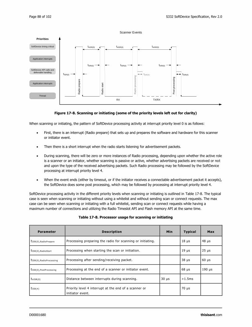
Page 88 of 102 S332 SoftDevice Specification, Rev 2.0
D00001680 thisisant.com
Figure 17-8. Scanning or initiating (some of the priority levels left out for clarity)
When scanning or initiating, the pattern of SoftDevice processing activity at interrupt priority level 0 is as follows:
First, there is an interrupt (Radio prepare) that sets up and prepares the software and hardware for this scanner
or initiator event.
Then there is a short interrupt when the radio starts listening for advertisement packets.
During scanning, there will be zero or more instances of Radio processing, depending upon whether the active role
is a scanner or an initiator, whether scanning is passive or active, whether advertising packets are received or not
and upon the type of the received advertising packets. Such Radio processing may be followed by the SoftDevice
processing at interrupt priority level 4.
When the event ends (either by timeout, or if the initiator receives a connectable advertisement packet it accepts),
the SoftDevice does some post processing, which may be followed by processing at interrupt priority level 4.
SoftDevice processing activity in the different priority levels when scanning or initiating is outlined in Table 17-8. The typical
case is seen when scanning or initiating without using a whitelist and without sending scan or connect requests. The max
case can be seen when scanning or initiating with a full whitelist, sending scan or connect requests while having a
maximum number of connections and utilizing the Radio Timeslot API and Flash memory API at the same time.
Table 17-8. Processor usage for scanning or initiating
Parameter Description Min Typical Max
tISR(0),RadioPrepare Processing preparing the radio for scanning or initiating. 18 μs 48 μs
tISR(0),RadioStart Processing when starting the scan or initiation. 19 μs 25 μs
tISR(0),RadioProcessing Processing after sending/receiving packet. 38 μs 60 μs
tISR(0),PostProcessing Processing at the end of a scanner or initiator event. 68 μs 190 μs
tnISR(0) Distance between interrupts during scanning. 30 μs >1.5ms
tISR(4) Priority level 4 interrupt at the end of a scanner or
initiator event.
70 μs
tnISR(0)
tISR(0)
Rad
io s
tart
Scanner Events
Ra
dio
pre
pa
re
tISR(4)
tnISR(0)
Post
pro
cessin
g
tISR(4)
Rad
io p
rocessin
g
tnISR(0)
RX TX/RX
tISR(0) tISR(0) tISR(0)
Priorities
Application interrupts
SoftDevice API calls and
deferrable handling
Application interrupts
Thread
SoftDevice timing critical
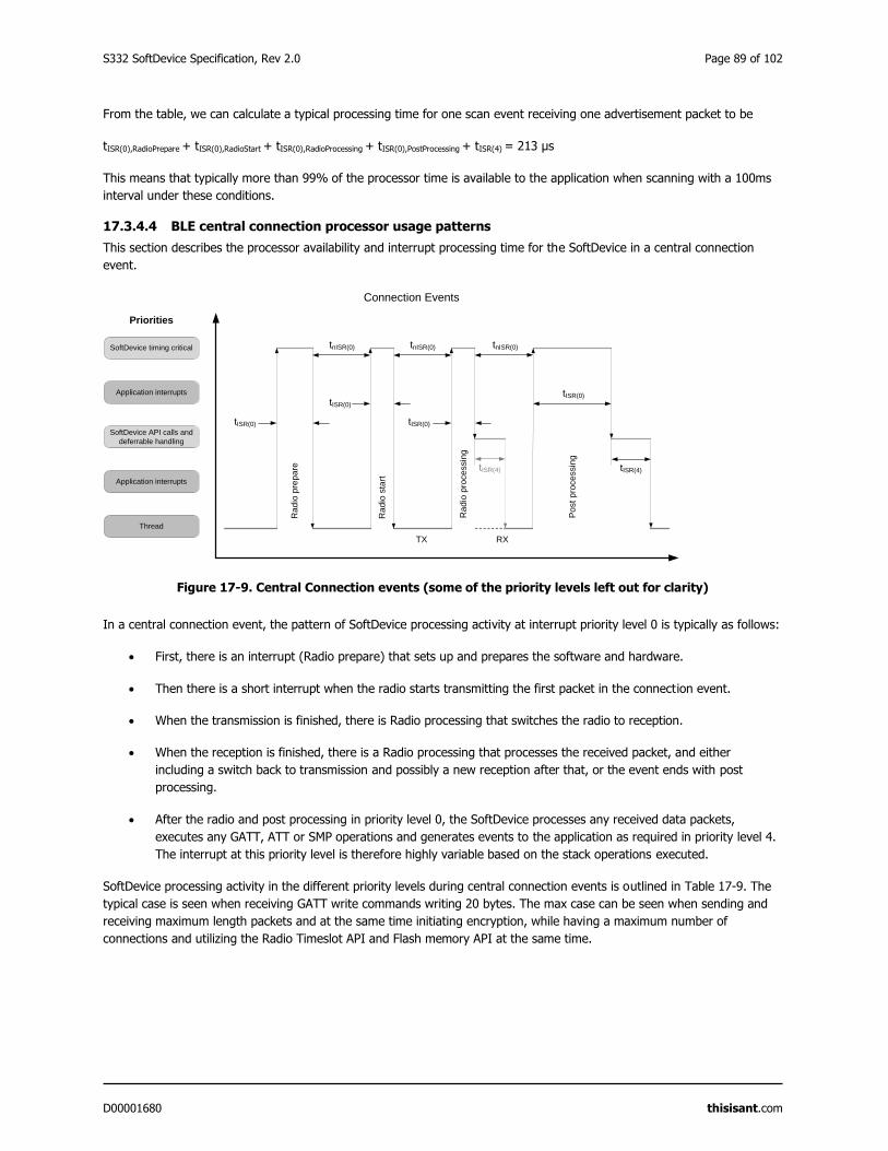
S332 SoftDevice Specification, Rev 2.0 Page 89 of 102
D00001680 thisisant.com
From the table, we can calculate a typical processing time for one scan event receiving one advertisement packet to be
tISR(0),RadioPrepare + tISR(0),RadioStart + tISR(0),RadioProcessing + tISR(0),PostProcessing + tISR(4) = 213 μs
This means that typically more than 99% of the processor time is available to the application when scanning with a 100ms
interval under these conditions.
17.3.4.4 BLE central connection processor usage patterns
This section describes the processor availability and interrupt processing time for the SoftDevice in a central connection
event.
Figure 17-9. Central Connection events (some of the priority levels left out for clarity)
In a central connection event, the pattern of SoftDevice processing activity at interrupt priority level 0 is typically as follows:
First, there is an interrupt (Radio prepare) that sets up and prepares the software and hardware.
Then there is a short interrupt when the radio starts transmitting the first packet in the connection event.
When the transmission is finished, there is Radio processing that switches the radio to reception.
When the reception is finished, there is a Radio processing that processes the received packet, and either
including a switch back to transmission and possibly a new reception after that, or the event ends with post
processing.
After the radio and post processing in priority level 0, the SoftDevice processes any received data packets,
executes any GATT, ATT or SMP operations and generates events to the application as required in priority level 4.
The interrupt at this priority level is therefore highly variable based on the stack operations executed.
SoftDevice processing activity in the different priority levels during central connection events is outlined in Table 17-9. The
typical case is seen when receiving GATT write commands writing 20 bytes. The max case can be seen when sending and
receiving maximum length packets and at the same time initiating encryption, while having a maximum number of
connections and utilizing the Radio Timeslot API and Flash memory API at the same time.
tnISR(0)
tISR(0)
tISR(0)
tISR(4)
Connection EventsR
ad
io p
rep
are
tnISR(0)
tISR(0)
Ra
dio
sta
rt
tnISR(0)
tISR(0)
Rad
io p
roce
ssin
g
Po
st
pro
ce
ssin
g
RXTX
Priorities
Application interrupts
SoftDevice API calls and
deferrable handling
Application interrupts
Thread
SoftDevice timing critical
tISR(4)
Page 90 of 102 S332 SoftDevice Specification, Rev 2.0
D00001680 thisisant.com
Table 17-9. Processor usage latency when connected (BLE)
Parameter Description Min Typical Max
tISR(0),RadioPrepare Processing preparing the radio for a connection event. 29 μs 47 μs
tISR(0),RadioStart Processing when starting the connection event. 19 μs 25 μs
tISR(0),RadioProcessing Processing after sending or receiving a packet. 30 μs 60 μs
tISR(0),PostProcessing Processing at the end of a connection event. 90 μs 230 μs
tnISR(0) Distance between connection event interrupts. 30 μs >195us
tISR(4) Priority level 4 interrupt after a packet is sent or
received.
40 μs
From the table, we can calculate a typical processing time for a central connection event where one packet is sent and
received to be
tISR(0),RadioPrepare + tISR(0),RadioStart + tISR(0),RadioProcessing + tISR(0),PostProcessing + 2 * tISR(4) = 248 μs
This means that typically more than 99% of the processor time is available to the application when one peripheral link is
established and one packet is sent in each direction with a 100ms connection interval.
17.3.5 Interrupt latency when using multiple modules, channels, and roles
Concurrent use of the Flash API, Radio Timeslot API, ANT channel(s) and/or BLE role(s) can affect the interrupt latency.
The same interrupt priority levels are used by all Flash API, Radio Timeslot API, ANT channels, and BLE roles. When using
more than one of these concurrently, their respective events can be scheduled back-to-back (section 9.2.4). In those cases,
the last interrupt in the activity by one module/channel/role can be directly followed by the first interrupt of the next
activity. Therefore, to find the real worst-case interrupt latency, the application developer must sum the latency of the first
and last interrupts for all combinations of processor usage.
Example: If the application uses the Radio Timeslot API while having a BLE advertiser running, the worst case interrupt
latency for an application interrupt is the largest of:
The worst case interrupt latency of the Radio Timeslot API
The worst case interrupt latency of the BLE advertiser role
The sum of the maximum time of the first interrupt of the Radio Timeslot API and the last interrupt of the BLE
advertiser role
The sum of the maximum time of the first interrupt of the BLE advertiser role and the last interrupt of the Radio
Timeslot API for the SoftDevice interrupts with higher priority level (lower numerical value) as the application interrupt.
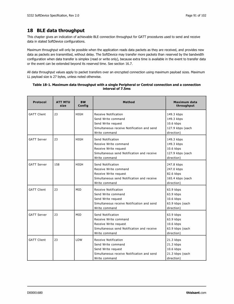
S332 SoftDevice Specification, Rev 2.0 Page 91 of 102
D00001680 thisisant.com
18 BLE data throughput
This chapter gives an indication of achievable BLE connection throughput for GATT procedures used to send and receive
data in stated SoftDevice configurations.
Maximum throughput will only be possible when the application reads data packets as they are received, and provides new
data as packets are transmitted, without delay. The SoftDevice may transfer more packets than reserved by the bandwidth
configuration when data transfer is simplex (read or write only), because extra time is available in the event to transfer data
or the event can be extended beyond its reserved time. See section 16.7.
All data throughput values apply to packet transfers over an encrypted connection using maximum payload sizes. Maximum
LL payload size is 27 bytes, unless noted otherwise.
Table 18-1. Maximum data throughput with a single Peripheral or Central connection and a connection interval of 7.5ms
Protocol ATT MTU size
BW Config
Method Maximum data throughput
GATT Client 23 HIGH Receive Notification
Send Write command
Send Write request
Simultaneous receive Notification and send
Write command
149.3 kbps
149.3 kbps
10.6 kbps
127.9 kbps (each
direction)
GATT Server 23 HIGH Send Notification
Receive Write command
Receive Write request
Simultaneous send Notification and receive
Write command
149.3 kbps
149.3 kbps
10.6 kbps
127.9 kbps (each
direction)
GATT Server 158 HIGH Send Notification
Receive Write command
Receive Write request
Simultaneous send Notification and receive
Write command
247.8 kbps
247.0 kbps
82.6 kbps
165.4 kbps (each
direction)
GATT Client 23 MID Receive Notification
Send Write command
Send Write request
Simultaneous receive Notification and send
Write command
63.9 kbps
63.9 kbps
10.6 kbps
63.9 kbps (each
direction)
GATT Server 23 MID Send Notification
Receive Write command
Receive Write request
Simultaneous send Notification and receive
Write command
63.9 kbps
63.9 kbps
10.6 kbps
63.9 kbps (each
direction)
GATT Client 23 LOW Receive Notification
Send Write command
Send Write request
Simultaneous receive Notification and send
Write command
21.3 kbps
21.3 kbps
10.6 kbps
21.3 kbps (each
direction)
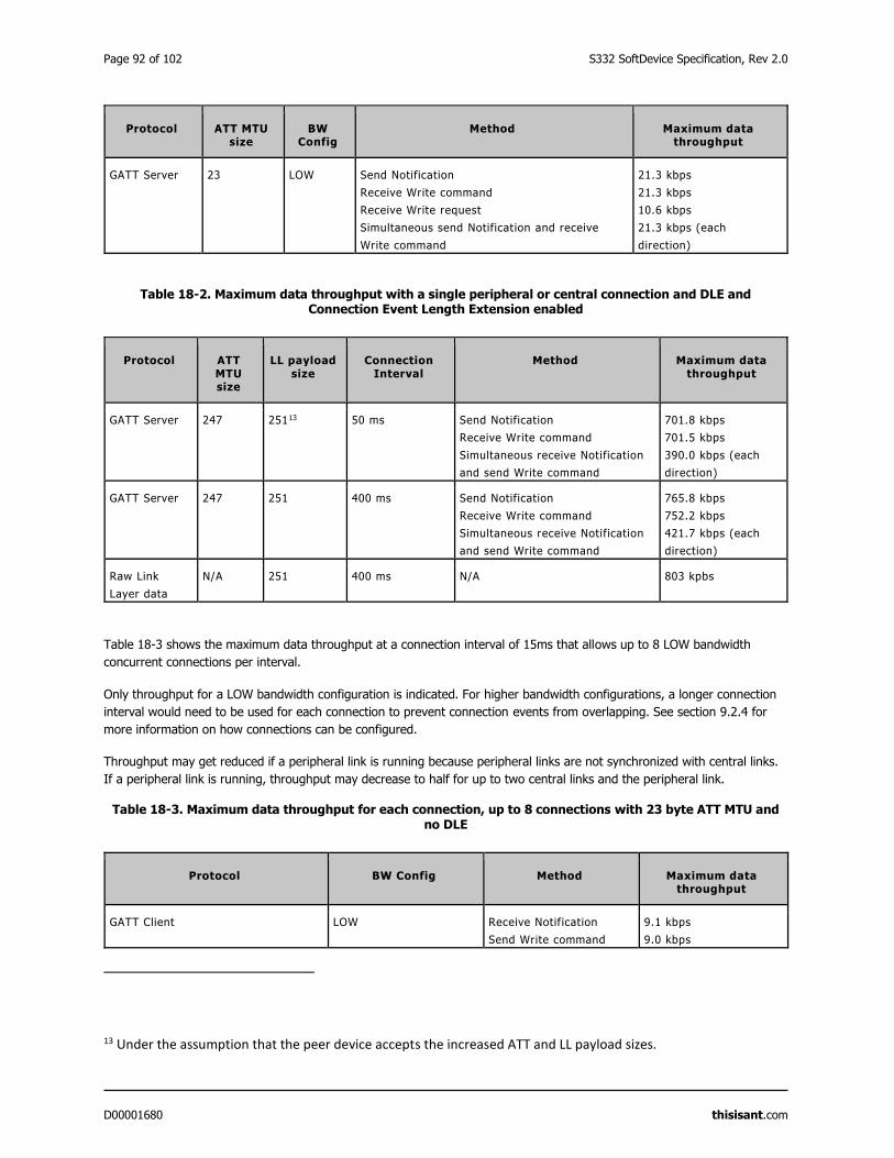
Page 92 of 102 S332 SoftDevice Specification, Rev 2.0
D00001680 thisisant.com
Protocol ATT MTU size
BW Config
Method Maximum data throughput
GATT Server 23 LOW Send Notification
Receive Write command
Receive Write request
Simultaneous send Notification and receive
Write command
21.3 kbps
21.3 kbps
10.6 kbps
21.3 kbps (each
direction)
Table 18-2. Maximum data throughput with a single peripheral or central connection and DLE and Connection Event Length Extension enabled
Protocol ATT MTU size
LL payload size
Connection Interval
Method Maximum data throughput
GATT Server 247 25113 50 ms Send Notification
Receive Write command
Simultaneous receive Notification
and send Write command
701.8 kbps
701.5 kbps
390.0 kbps (each
direction)
GATT Server 247 251 400 ms Send Notification
Receive Write command
Simultaneous receive Notification
and send Write command
765.8 kbps
752.2 kbps
421.7 kbps (each
direction)
Raw Link
Layer data
N/A 251 400 ms N/A 803 kpbs
Table 18-3 shows the maximum data throughput at a connection interval of 15ms that allows up to 8 LOW bandwidth
concurrent connections per interval.
Only throughput for a LOW bandwidth configuration is indicated. For higher bandwidth configurations, a longer connection
interval would need to be used for each connection to prevent connection events from overlapping. See section 9.2.4 for
more information on how connections can be configured.
Throughput may get reduced if a peripheral link is running because peripheral links are not synchronized with central links.
If a peripheral link is running, throughput may decrease to half for up to two central links and the peripheral link.
Table 18-3. Maximum data throughput for each connection, up to 8 connections with 23 byte ATT MTU and no DLE
Protocol BW Config Method Maximum data throughput
GATT Client LOW Receive Notification
Send Write command
9.1 kbps
9.0 kbps
13 Under the assumption that the peer device accepts the increased ATT and LL payload sizes.
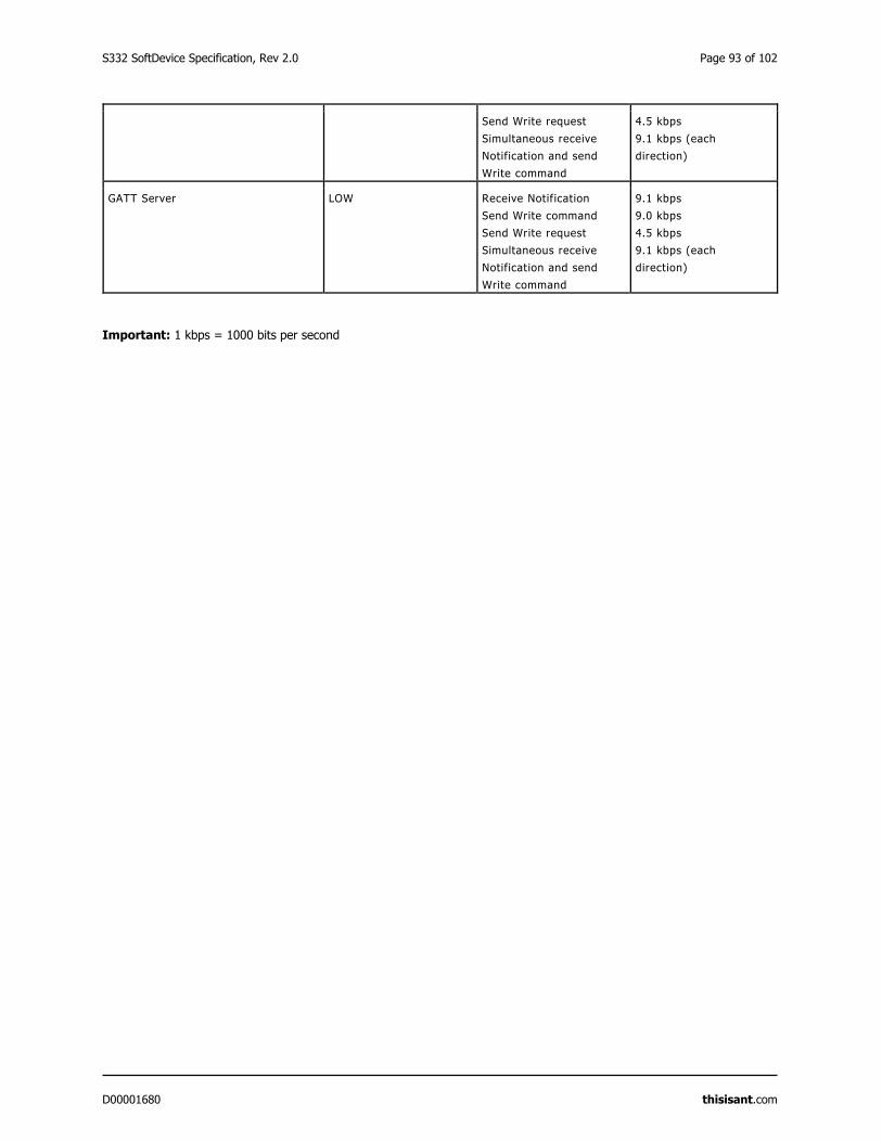
S332 SoftDevice Specification, Rev 2.0 Page 93 of 102
D00001680 thisisant.com
Send Write request
Simultaneous receive
Notification and send
Write command
4.5 kbps
9.1 kbps (each
direction)
GATT Server LOW Receive Notification
Send Write command
Send Write request
Simultaneous receive
Notification and send
Write command
9.1 kbps
9.0 kbps
4.5 kbps
9.1 kbps (each
direction)
Important: 1 kbps = 1000 bits per second
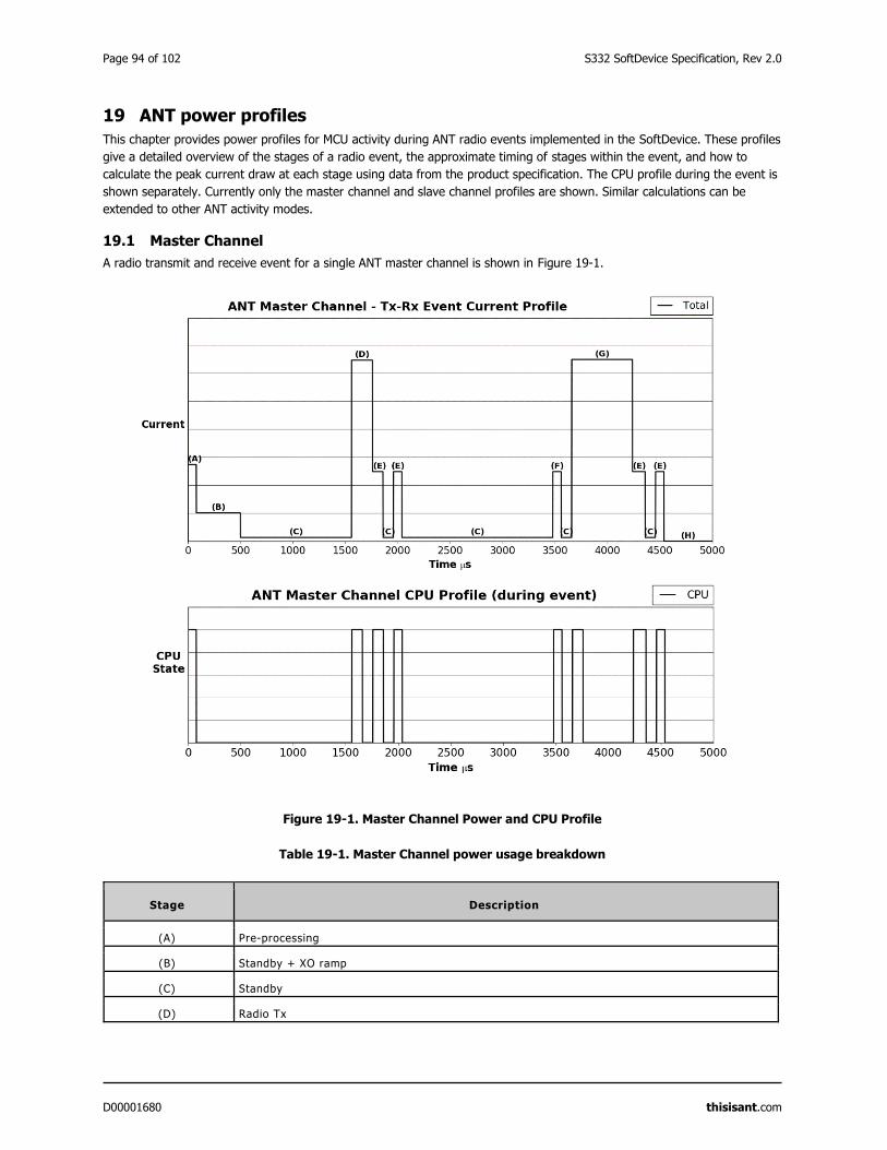
Page 94 of 102 S332 SoftDevice Specification, Rev 2.0
D00001680 thisisant.com
19 ANT power profiles
This chapter provides power profiles for MCU activity during ANT radio events implemented in the SoftDevice. These profiles
give a detailed overview of the stages of a radio event, the approximate timing of stages within the event, and how to
calculate the peak current draw at each stage using data from the product specification. The CPU profile during the event is
shown separately. Currently only the master channel and slave channel profiles are shown. Similar calculations can be
extended to other ANT activity modes.
19.1 Master Channel
A radio transmit and receive event for a single ANT master channel is shown in Figure 19-1.
Figure 19-1. Master Channel Power and CPU Profile
Table 19-1. Master Channel power usage breakdown
Stage Description
(A) Pre-processing
(B) Standby + XO ramp
(C) Standby
(D) Radio Tx
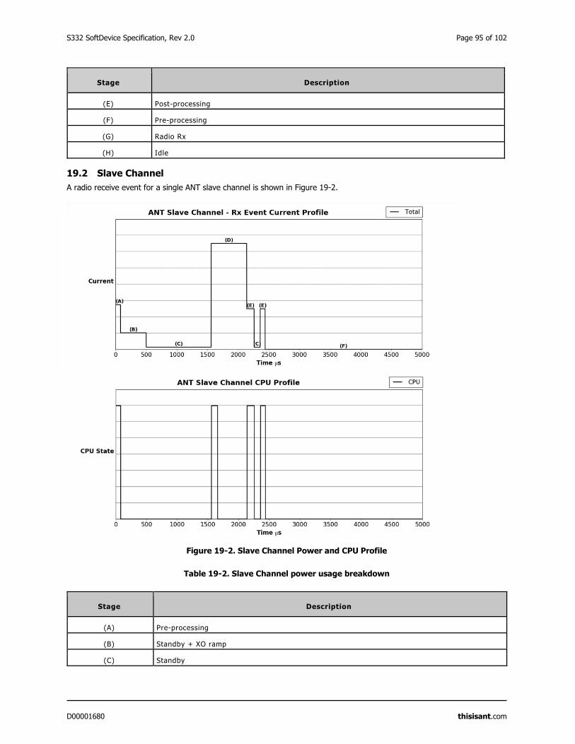
S332 SoftDevice Specification, Rev 2.0 Page 95 of 102
D00001680 thisisant.com
Stage Description
(E) Post-processing
(F) Pre-processing
(G) Radio Rx
(H) Idle
19.2 Slave Channel
A radio receive event for a single ANT slave channel is shown in Figure 19-2.
Figure 19-2. Slave Channel Power and CPU Profile
Table 19-2. Slave Channel power usage breakdown
Stage Description
(A) Pre-processing
(B) Standby + XO ramp
(C) Standby

Page 96 of 102 S332 SoftDevice Specification, Rev 2.0
D00001680 thisisant.com
Stage Description
(D) Radio Rx
(E) Post-processing
(F) Idle

S332 SoftDevice Specification, Rev 2.0 Page 97 of 102
D00001680 thisisant.com
20 BLE power profiles
The power profile diagrams in this chapter give an overview of the stages within a Bluetooth® low energy Radio Event
implemented by the SoftDevice. The profiles illustrate battery current versus time and briefly describe the stages that could
be observed.
These profiles are based on typical events with empty packets. In all cases, ‘Standby’ is a state of the SoftDevice where all
peripherals are idle.
20.1 Advertising event
This section gives an overview of the power profile of the advertising event implemented in the SoftDevice.
Figure 20-1. Advertising event
Table 20-1. Advertising event
Stage Description
(A) Pre-processing (CPU)
(B) Standby + HFXO ramp
(C) Standby
(D) Radio startup
(E) Radio Tx
(F) Radio switch
(G) Radio Rx
(H) Post-processing (CPU)
(I) Standby
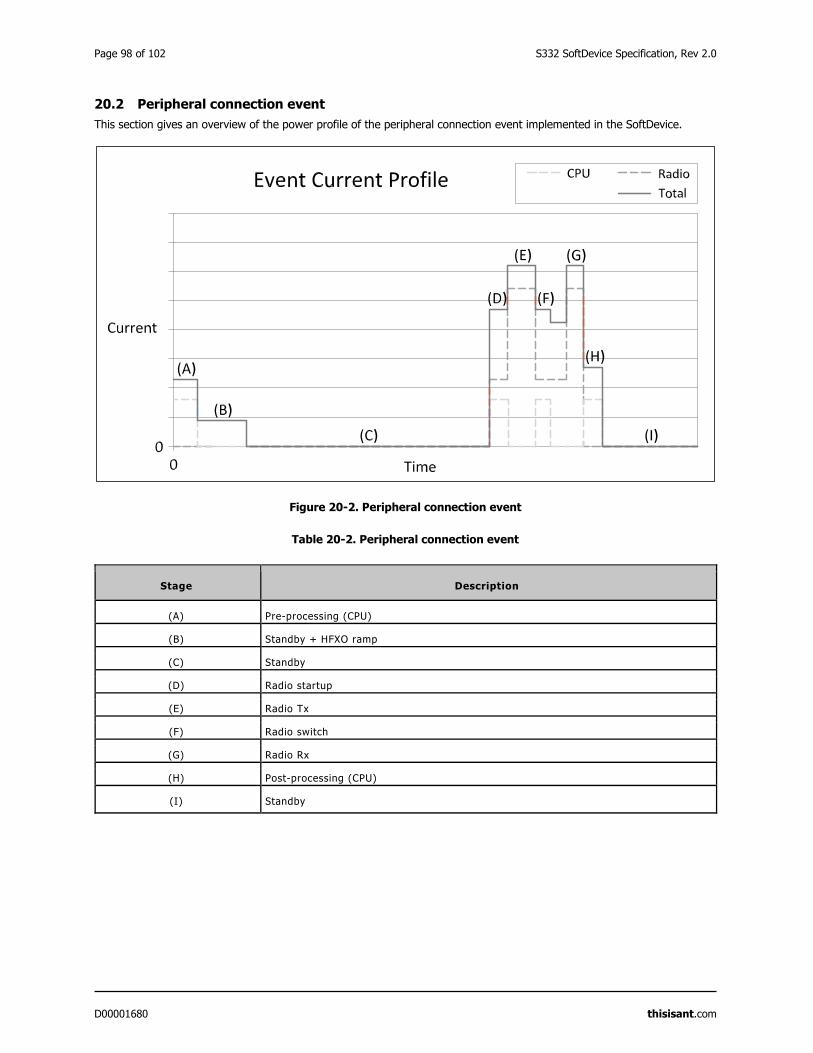
Page 98 of 102 S332 SoftDevice Specification, Rev 2.0
D00001680 thisisant.com
20.2 Peripheral connection event
This section gives an overview of the power profile of the peripheral connection event implemented in the SoftDevice.
Figure 20-2. Peripheral connection event
Table 20-2. Peripheral connection event
Stage Description
(A) Pre-processing (CPU)
(B) Standby + HFXO ramp
(C) Standby
(D) Radio startup
(E) Radio Tx
(F) Radio switch
(G) Radio Rx
(H) Post-processing (CPU)
(I) Standby
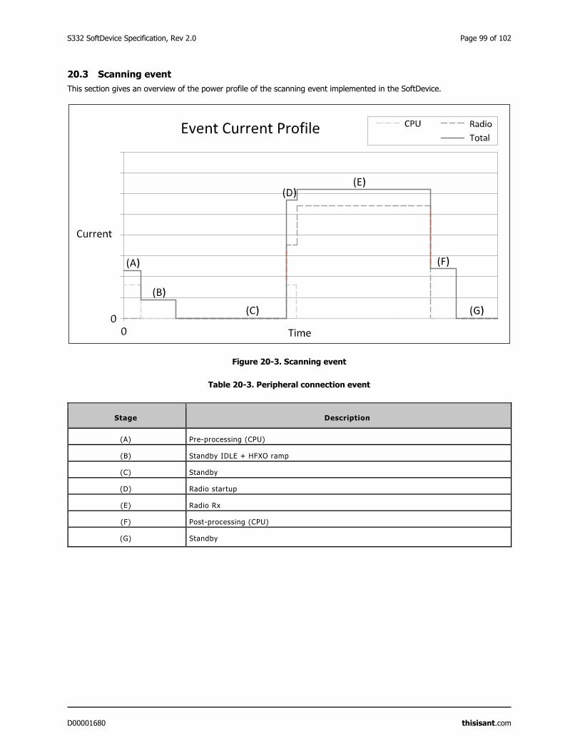
S332 SoftDevice Specification, Rev 2.0 Page 99 of 102
D00001680 thisisant.com
20.3 Scanning event
This section gives an overview of the power profile of the scanning event implemented in the SoftDevice.
Figure 20-3. Scanning event
Table 20-3. Peripheral connection event
Stage Description
(A) Pre-processing (CPU)
(B) Standby IDLE + HFXO ramp
(C) Standby
(D) Radio startup
(E) Radio Rx
(F) Post-processing (CPU)
(G) Standby
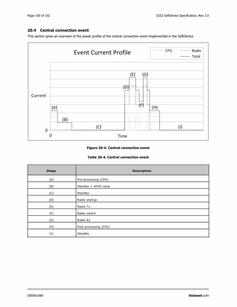
Page 100 of 102 S332 SoftDevice Specification, Rev 2.0
D00001680 thisisant.com
20.4 Central connection event
This section gives an overview of the power profile of the central connection event implemented in the SoftDevice.
Figure 20-4. Central connection event
Table 20-4. Central connection event
Stage Description
(A) Pre-processing (CPU)
(B) Standby + HFXO ramp
(C) Standby
(D) Radio startup
(E) Radio Tx
(F) Radio switch
(G) Radio Rx
(H) Post-processing (CPU)
(I) Standby
S332 SoftDevice Specification, Rev 2.0 Page 101 of 102
D00001680 thisisant.com
21 SoftDevice identification and revision scheme
The SoftDevices are identified by the SoftDevice part code, a qualified IC part code (for example, nRF52832), and a version
string.
The identification scheme for SoftDevices consists of the following items:
For revisions of the SoftDevice which are production qualified, the version string consists of major, minor, and
revision numbers only, as described in the table below.
For revisions of the SoftDevice which are not production qualified, a test qualification level (alpha/beta) and a
build number are appended to the version string.
For example: s110_nrf51_1.2.3.alpha4, where major = 1, minor = 2, revision = 3, test qualification level is alpha
and build number = 4. Additional examples are given in Table 21-2.
Table 21-1. Revision scheme
Revision Description
Major increments Modifications to the API or the function or behaviour of the
implementation or part of it have changed.
Changes as per minor increment may have been made.
Application code will not be compatible without some modification.
Minor increments Additional features and/or API calls are available.
Application code may have to be modified to take advantage of new
features.
Revision increments Issues have been resolved or improvements to performance implemented.
Existing application code will not require any modification.
Test qualification level Refer to Table 21-3.
Build number increment (if present) New build of non-production versions.
Table 21-2. SoftDevice revision examples
Sequence number Description
s332_nrf52_1.2.3.alpha1 Revision 1.2.3, first build qualified at alpha level
s332_nrf52_1.2.3.alpha2 Revision 1.2.3, second build qualified at alpha level
s332_nrf52_1.2.3.beta5 Revision 1.2.3, fifth build qualified at beta level
s332_nrf52_1.2.3 Revision 1.2.3, qualified at production level
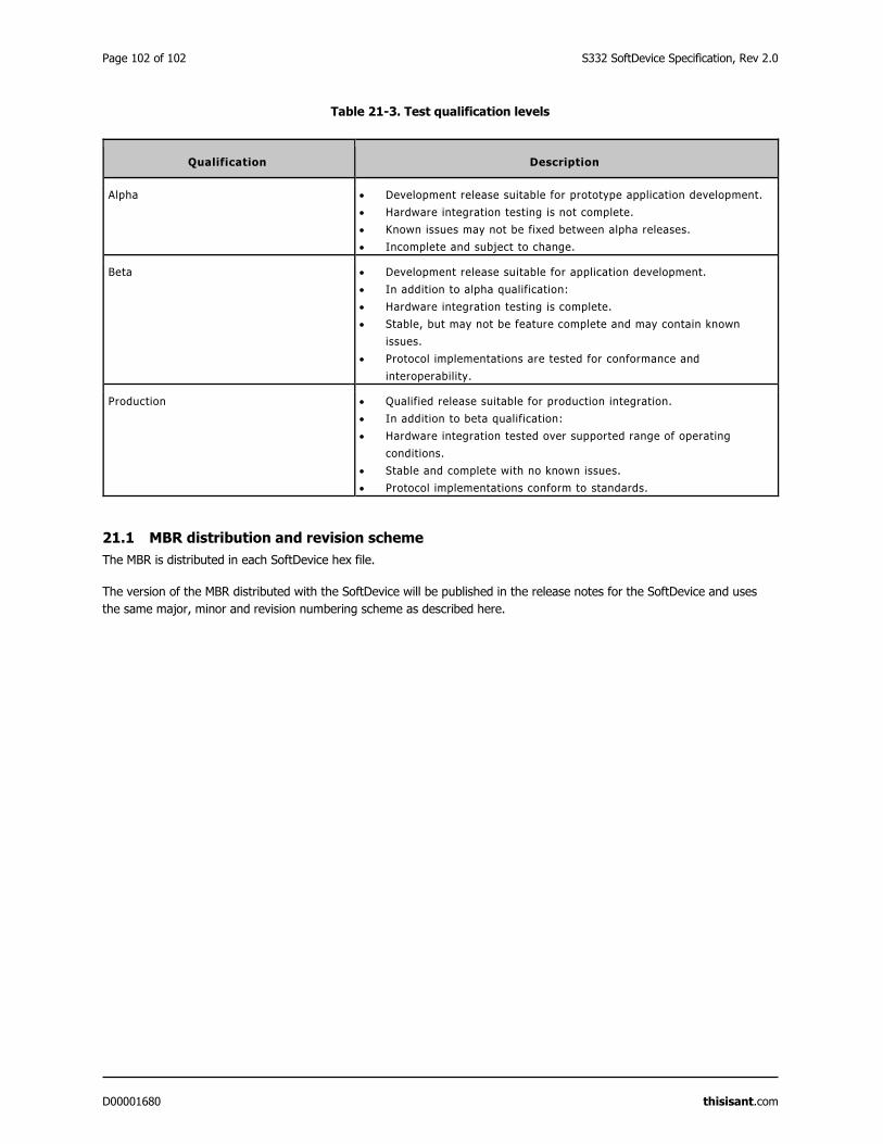
Page 102 of 102 S332 SoftDevice Specification, Rev 2.0
D00001680 thisisant.com
Table 21-3. Test qualification levels
Qualification Description
Alpha Development release suitable for prototype application development.
Hardware integration testing is not complete.
Known issues may not be fixed between alpha releases.
Incomplete and subject to change.
Beta Development release suitable for application development.
In addition to alpha qualification:
Hardware integration testing is complete.
Stable, but may not be feature complete and may contain known
issues.
Protocol implementations are tested for conformance and
interoperability.
Production Qualified release suitable for production integration.
In addition to beta qualification:
Hardware integration tested over supported range of operating
conditions.
Stable and complete with no known issues.
Protocol implementations conform to standards.
21.1 MBR distribution and revision scheme
The MBR is distributed in each SoftDevice hex file.
The version of the MBR distributed with the SoftDevice will be published in the release notes for the SoftDevice and uses
the same major, minor and revision numbering scheme as described here.
Related Documents


![[Insert doc title]](https://static.cupdf.com/doc/110x72/620fc8af7c0675709651df93/insert-doc-title.jpg)