Energy Management Subcommittee AMERICAN NATIONAL STANDARD ANSI/SCTE 203 2019 Product Environmental Requirements for Cable Telecommunications Facilities – Test Methods

Welcome message from author
This document is posted to help you gain knowledge. Please leave a comment to let me know what you think about it! Share it to your friends and learn new things together.
Transcript

Energy Management Subcommittee
AMERICAN NATIONAL STANDARD
ANSI/SCTE 203 2019
Product Environmental Requirements for Cable Telecommunications Facilities – Test Methods

ANSI/SCTE 203 2019
AMERICAN NATIONAL STANDARD © SCTE•ISBE 2
NOTICE The Society of Cable Telecommunications Engineers (SCTE) / International Society of Broadband Experts (ISBE) Standards and Operational Practices (hereafter called “documents”) are intended to serve the public interest by providing specifications, test methods and procedures that promote uniformity of product, interchangeability, best practices and ultimately the long-term reliability of broadband communications facilities. These documents shall not in any way preclude any member or non-member of SCTE•ISBE from manufacturing or selling products not conforming to such documents, nor shall the existence of such standards preclude their voluntary use by those other than SCTE•ISBE members. SCTE•ISBE assumes no obligations or liability whatsoever to any party who may adopt the documents. Such adopting party assumes all risks associated with adoption of these documents, and accepts full responsibility for any damage and/or claims arising from the adoption of such documents. Attention is called to the possibility that implementation of this document may require the use of subject matter covered by patent rights. By publication of this document, no position is taken with respect to the existence or validity of any patent rights in connection therewith. SCTE•ISBE shall not be responsible for identifying patents for which a license may be required or for conducting inquiries into the legal validity or scope of those patents that are brought to its attention. Patent holders who believe that they hold patents which are essential to the implementation of this document have been requested to provide information about those patents and any related licensing terms and conditions. Any such declarations made before or after publication of this document are available on the SCTE•ISBE web site at http://www.scte.org.
All Rights Reserved
© Society of Cable Telecommunications Engineers, Inc. 2019 140 Philips Road Exton, PA 19341

ANSI/SCTE 203 2019
AMERICAN NATIONAL STANDARD © SCTE•ISBE 3
Contents 1 Introduction ........................................................................................................................................................... 5
1.1 Purpose .......................................................................................................................................................... 5
1.2 Scope ............................................................................................................................................................. 5
1.3 Requirements Syntax ..................................................................................................................................... 5
1.4 Acronyms ....................................................................................................................................................... 6
2 Physical Requirements .......................................................................................................................................... 7
2.1 Frame and Cabinet ......................................................................................................................................... 7
2.2 Equipment Static Load (chassis static force test) ........................................................................................... 7
2.3 Impact Force Resistance ................................................................................................................................ 7
2.4 Microphonics Emissions ................................................................................................................................ 7
2.5 Dissimilar Metals ........................................................................................................................................... 8
2.6 Equipment labels and markings ..................................................................................................................... 9
2.6.1 Packaging and Shipping Labels ............................................................................................................... 9
2.6.2 ESD Labels and Documentation .............................................................................................................. 9
3 Environmental Requirements .............................................................................................................................. 10
3.1 Climate ........................................................................................................................................................ 10
3.1.1 Transportation/Storage Temperature and Humidity .............................................................................. 10
3.1.2 Operating Temperature, Humidity, and Test Description ...................................................................... 15
3.1.3 Operating Altitude Test Description ...................................................................................................... 15
3.1.4 Operating Internal Temperature Margin Test Description ..................................................................... 16
3.1.5 Equipment Cooling Fans ....................................................................................................................... 16
3.1.6 Equipment Surface Temperatures .......................................................................................................... 16
3.2 Shock and Vibration .................................................................................................................................... 16
3.2.1 Packaged Equipment Free Fall Drop ..................................................................................................... 16
3.2.2 Unpacked Equipment Free Fall Drop .................................................................................................... 16
3.2.3 Transportation Mechanical Shock ......................................................................................................... 16
3.2.4 Transportation Mechanical Vibration .................................................................................................... 16
3.2.5 Operating Mechanical Vibration ....................................................................................................... 16
3.2.6 Operating Mechanical Shock ................................................................................................................. 17
3.2.7 Earthquake resistance ........................................................................................................................ 17
3.3 Contaminant Resistance ............................................................................................................................... 17
3.3.1 Equipment Airborne Contaminant Resistance ....................................................................................... 17
3.3.2 Solvent Resistance ................................................................................................................................. 17
3.4 Equipment Safety......................................................................................................................................... 18
ANSI/SCTE 203 2019
AMERICAN NATIONAL STANDARD © SCTE•ISBE 4
3.4.1 Safety of Information Technology equipment ....................................................................................... 18
3.4.2 Laser safety ............................................................................................................................................ 18
3.4.3 Fire safety .............................................................................................................................................. 18
3.4.4 Equipment Alarms and Automatic Shut Down ...................................................................................... 18
4 Electrical Requirements ...................................................................................................................................... 19
4.1 Electromagnetic compatibility (EMC) ......................................................................................................... 19
4.1.1 Radiated Emissions ................................................................................................................................ 19
4.1.2 Conducted Emissions ............................................................................................................................. 19
4.1.3 Immunity Criteria .................................................................................................................................. 20
4.2 Grounding and Bonding .............................................................................................................................. 21
5 Sustainability Requirements ............................................................................................................................... 22
5.1 Product Development .................................................................................................................................. 22
5.1.1 Life Cycle Thinking ............................................................................................................................... 22
5.1.2 Material Efficiency ................................................................................................................................ 22
5.1.3 Energy Efficiency .................................................................................................................................. 22
5.1.4 Consumables and Batteries .................................................................................................................... 22
5.2 Product Operation ........................................................................................................................................ 22
5.2.1 Airflow ................................................................................................................................................... 22
5.2.2 Air filters ................................................................................................................................................ 22
5.2.3 Heat Release .......................................................................................................................................... 22
5.2.4 Energy Efficiency .................................................................................................................................. 22
5.2.5 Emissions ............................................................................................................................................... 23
5.3 Product Lifetime .......................................................................................................................................... 23
5.4 Product Disposal .......................................................................................................................................... 23
6 Quality Requirements ......................................................................................................................................... 24
6.1 Reliability .................................................................................................................................................... 24
6.2 Highly Accelerated Life Testing (HALT) ................................................................................................... 24
Appendix A – Normative References .......................................................................................................................... 25
Appendix B – Informative References ........................................................................................................................ 29
List of Tables Table 1-1: Acronyms ..................................................................................................................................................... 6 Table 2-1: Anodic Index……..........................................................................................................................................................................9 Table 3-1: Random Vibration Test Method.............................................................................................................................................19

ANSI/SCTE 203 2019
AMERICAN NATIONAL STANDARD © SCTE•ISBE 5
1 Introduction
1.1 Purpose The specification purpose is to define test methods to evaluate equipment compliance with criteria specified in ANSI/SCTE 186 2012.
1.2 Scope This document is identical to SCTE 203 2014 except for informative components which may have been updated such as the title page, NOTICE text, headers and footers. No normative changes have been made to this document. This document specifies physical, environmental, electrical, and sustainability test procedures to evaluate equipment compliance with requirements defined in ANSI/SCTE 186 2012.
1.3 Requirements Syntax Throughout this document, specific words are used to define the requirements significance. These words are: “shall" This word means that the item is an absolute requirement of this specification. "shall not" This phrase means that the item is an absolute prohibition of this specification. "should" This word means that there may be valid reasons in particular circumstances to
ignore this item, but the full implications should be understood and the case carefully weighed before choosing a different course.
"should not" This phrase means that there may exist valid reasons in particular circumstances when the listed behavior is acceptable or even useful, but the full implications should be understood and the case carefully weighed before implementing any behavior described with this label.
"may" This word means that this item is truly optional. One vendor may choose to include the item because a particular marketplace requires it or because it enhances the product, for example; another vendor may omit the same item.

ANSI/SCTE 203 2019
AMERICAN NATIONAL STANDARD © SCTE•ISBE 6
1.4 Acronyms
Table 1-1: Acronyms AC Alternating Current ASTM American Society for Testing and Materials ANSI American National Standards Institute ASD Acceleration Spectral Density ASHRAE American Society of Heating, Refrigerating and Air-conditioning ATIS Alliance for Telecommunications Industry Solutions CENELEC European Committee for Electrotechnical Standardization CFR Code of Federal Regulations (US) CO Central Office DC Direct Current DOCSIS™ Data Over Cable Service Interface Specification eCFR Electronic Code of Federal Regulations (US) EC European Community ECMA Ecma International®
(formally European Computer Manufacturers Association) EFT Electronic Fast Transient EIA Electronic Industries Alliance EMC Electromagnetic Compatibility EMI Electromagnetic Interference ETSI European Telecommunications Standards Institute EUT Equipment Under Test FRU Field Replaceable Unit IEC International Electrotechnical Commission ITU International Telecommunication Union NRTL Nationally Recognized Testing Laboratory OSHA Occupational Safety and Health Administration (US Dept. of Labor) OSP Outside Plant PacketCable™ A CableLabs® led initiative to develop interoperable interface specifications for delivering
advanced, real-time multimedia services over two-way cable plant RoHS Restriction of Hazardous Substances SPEC Standard Performance Evaluation Corporation TCG Telecommunications Carrier Group TIA Telecommunications Industry Association U Unit, Short for Rack-Unit, Measure of vertical rack space, 1U=1.75” (44.45mm) UPS Uninterruptible Power Supply WEEE Waste Electrical and Electronic Equipment

ANSI/SCTE 203 2019
AMERICAN NATIONAL STANDARD © SCTE•ISBE 7
2 Physical Requirements
2.1 Frame and Cabinet Refer to ANSI T1.336-2009 for test procedures.
2.2 Equipment Static Load (chassis static force test) No mechanical damages or visible deformation, exposure to shock hazard or sharp edges shall occur when the equipment housing is subjected to a static force of 25lbf (111N) applied via a 1.2 inch diameter steel hemisphere for a period of one (1) minute. The equipment shall withstand the static load when applied to various locations on the top, bottom, right side, and left side of the equipment both when it is free standing and when it is housed or mounted using the vendor supplied mounting brackets.
2.3 Impact Force Resistance The external metal enclosure of the device / product (intended for use in a controlled environment) shall be subjected to an impact generated by a free-falling smooth, solid steel sphere 2 inches (5.08cm) in diameter and weighing approximately 1.18 lbs (0.535Kg). • The sphere is to fall freely form a height of 51 inches (129.54cm) at various locations on the outside of the
enclosure. • The tests shall not result in permanent distortion to the extent that wire to ground or chassis spacing is
reduced below the following values: For 0 to 50 Vrms peak: 1/16” For >50 to 150 Vrms peak: 1/4" For 150 to 600 Vrms peak: 1/2"
• The tests shall not result in any distortion that produces contact of the enclosure with un-insulated electrically active parts other than those connected in a low voltage circuit.
• The tests shall not result in the unit developing any opening(s) that expose electrically active un-insulated parts that create a risk of electrical shock or high energy current levels.
2.4 Microphonics Emissions • The device / product shall withstand minimum impact energy of 0.7 Newton-meters (Nm) applied to
the device / product at various chassis locations without harmful or detrimental effect to any functional service provided by the test specimen (i.e., bit errors, spurious emissions, macro-blocking, interruption, lock-up or any other signal flow impairment).
• Microphonics impacts should be made with a calibrated impact hammer such as the E D &D Models 5110 or F22.50 (or equivalent).
• Information on the models listed above may be reviewed at http://www.productsafet.com. • Specification reference for the type of impact hammer to be used is IEC 68-2-63 / 1991 (or latest
version). • Impacts shall be imparted to each of the six operational planes of the device / product to be tested. • Depending upon the size of the product each operational plane should be divided into one or more
areas and multiple impacts should be imparted to each area. • Appropriate notations shall be made as to the location where the microphonics impact force is applied
when any and all signal flow impairments are seen. • Documentation should include written notes, diagrams, pictures, etc. • Measurements shall be made while any and all signal flow(s) is (are) monitored for discontinuities and
/ or interruptions

ANSI/SCTE 203 2019
AMERICAN NATIONAL STANDARD © SCTE•ISBE 8
2.5 Dissimilar Metals Inspect and determine compliance by analysis using the following method:
• Galvanic Compatibility is defined as the differential in Anodic Index Voltage between the various metals at the junction. The maximum Anodic Index (V) differential limit for equipment shall not be greater than +/-0.50 Volt. Galvanic compatibility
The compatibility of two different metals may be predicted by consideration of their "Anodic Index". This parameter is a measure of the electrochemical voltage that will be developed between the metal and gold. To find the relative voltage of a pair of metals it is only required to substract their Anodic Indexes.[9] For normal environments, such as storage in warehouses or non-temperature and humidity controlled environments, there should not be more than 0.25 V difference in the "Anodic Index". For controlled environments, in which temperature and humidity are controlled, 0.50 V can be tolerated. For harsh environments, such as outdoors, high humidity, and salt environments, there should be not more than 0.15 V difference in the "Anodic Index". For example; gold - silver would have a difference of 0.15V being acceptable [10] Often when design requires that dissimilar metals come in contact, the galvanic compatibility is managed by finishes and plating. The finishing and plating selected facilitates the dissimilar materials being in contact and protect the base materials from corrosion.[10]
Table 2-1: Anodic Index Table Anodic index[10]
Metal Index (V)
Most Cathodic
Gold, solid and plated, Gold-platinum alloy -0.00
Rhodium plated on silver-plated copper -0.05
Silver, solid or plated; monel metal. High nickel-copper alloys -0.15
Nickel, solid or plated, titanium an s alloys, Monel -0.30
Copper, solid or plated; low brasses or bronzes; silver solder; German silvery high copper-nickel alloys; nickel-chromium alloys -0.35
Brass and bronzes -0.40
High brasses and bronzes -0.45
18% chromium type corrosion-resistant steels -0.50
Chromium plated; tin plated; 12% chromium type corrosion-resistant steels -0.60
Tin-plate; tin-lead solder -0.65
Lead, solid or plated; high lead alloys -0.70
2000 series wrought aluminum -0.75
Iron, wrought, gray or malleable, plain carbon and low alloy steels -0.85
Aluminum, wrought alloys other than 2000 series aluminum, cast alloys of the silicon type -0.90
Aluminum, cast alloys other than silicon type, cadmium, plated and chromate -0.95

ANSI/SCTE 203 2019
AMERICAN NATIONAL STANDARD © SCTE•ISBE 9
Hot-dip-zinc plate; galvanized steel -1.20
Zinc, wrought; zinc-base die-casting alloys; zinc plated -1.25
Magnesium & magnesium-base alloys, cast or wrought -1.75
Beryllium -1.85
2.6 Equipment labels and markings Evaluate by inspection
1. Equipment vendor and product identification shall be visible when the unit is installed. 2. Labels for equipment user panels, connectors, controls, and power connections shall be shall be visible
when unit is installed and shall be located near their intended function. 3. Equipment certifications, compliances, approvals, and warning labels shall be visible when the unit is
installed and shall be provided in the equipment user documentation. 4. Labels that display serial numbers, MAC addresses and similar information shall be visible when the
equipment is installed and shall be implemented in light text on a dark background to assure legibility in non-optimum lighting.
5. Labels shall not peel, wear, crack, fade or blister under the environmental conditions in which the equipment will operate. Compliance may be evidenced by any of the following methods:
a. Using a permanent ink/typing ribbon meeting the requirements of ANSI/UL 969 or CAN/CSA No. 0.15
b. Use of a combination of materials and printing method accepted as a UL PGJI2 label system c. Shelf level equipment labels shall not be placed on the top, bottom, or side, e.g., shelf level
equipment labels shall be visible when the equipment is installed. d. Equipment should provide an area to affix a MSO placed equipment barcode or equivalent label.
6. Laser light emitting ports shall be capped and include a yellow warning label warning of the presence of laser light emissions.
2.6.1 Packaging and Shipping Labels Evaluate by inspection
1. Equipment package device bar code shall be placed such that it can be read and/or scanned without removing the equipment from its package or wrapping material.
2. Equipment shipping package shall have bar codes indicating its contents placed on the front upright surface.
3. Equipment packaging shall comply with Outer Shipping Container Bar Code Label Standard CEA556C and Product Package Bar Code Label Standard for Non-Retail Applications CEA624A.
2.6.2 ESD Labels and Documentation Evaluate by inspection
1. Equipment shall be labeled in compliance with EIA-471-1996, Symbol and Label for Electrostatic Sensitive Devices.
2. The ESD label should be located on the equipment front. Alternative locations are acceptable if there is no room for a front of equipment label.
3. Equipment documentation shall specify any ESD sensitivity issues. 4. Instructions and procedures to prevent ESD problems shall be provided in the equipment user
documentation

ANSI/SCTE 203 2019
AMERICAN NATIONAL STANDARD © SCTE•ISBE 10
3 Environmental Requirements This section documents equipment transportation, storage, and operating environmental test methods.
3.1 Climate
3.1.1 Transportation/Storage Temperature and Humidity Low Temperature Exposure and Thermal Shock Test Description Transportation/Storage low temperature exposure compliance shall be implemented and documented as specified in IEC 60068-2-1, Test Method Ab.
The following test sequence shall be executed:
1. Confirm EUT functions normally 2. Place the packaged and non-powered EUT in a test chamber and achieve EUT stability at 23⁰C. 3. Transition the EUT to -40⁰C at a 30⁰C/Hr rate. Relative humidity is not controlled. 4. Maintain the EUT at -40⁰C for 72 hours. Relative humidity is not controlled. 5. Transition the EUT to ambient room temperature and relative humidity in ≤ 5 minutes. 6. Remove the EUT from its package and allow time for the EUT to thermally stabilize to room temperature. 7. Power on the EUT and confirm normal operation without impairment.
The test procedure specified in GR-63-CORE, Issue 3, March 2006; Section 5.1.1.1 may be used as an alternative method to assure compliance with transportation/storage high temperature exposure and thermal shock. The test sequence is the same as described above.
3.1.1.1 High Temperature Exposure and Thermal Shock Test Description Transportation/Storage high temperature exposure compliance shall be confirmed and documented as specified in IEC 60068-2-2 Test Method Bb: Dry Heat.
-45-40-35-30-25-20-15-10-505
10152025
0 2 4 6 8 10 12 14 16 18 20 22 24 26 28 30 32 34 36 38 40 42 44 46 48 50 52 54 56 58 60 62 64 66 68 70 72 74 76
Deg
rees
C
Hours

ANSI/SCTE 203 2019
AMERICAN NATIONAL STANDARD © SCTE•ISBE 11
The following test sequence shall be executed:
1. Confirm EUT functions normally 2. Place the packaged and non-powered EUT in a test chamber and achieve EUT stability at 23⁰C. 3. Transition the EUT to 70⁰C at a 30⁰C/Hr rate. Relative humidity is not controlled. 4. Maintain the EUT at 70⁰C for 72 hours. Relative humidity is not controlled. 5. Transition the EUT to ambient room temperature and relative humidity in ≤ 5 minutes. 6. Remove the EUT from its package and allow time for the EUT to thermally stabilize to room temperature. 7. Power on the EUT and confirm normal operation without impairment.
The test procedure specified in GR-63-CORE, Issue 3, March 2006; Section 5.1.1.3 may be used as an alternative method to assure compliance transportation/Storage high temperature exposure and thermal shock. The test sequence is the same as described above with the exception that relative humidity is controlled.
3.1.1.2 High Relative Humidity Exposure Test Description Transportation/Storage high relative humidity exposure shall be confirmed and documented as specified in GR-63-CORE, Issue 3, March 2006; Section 5.1.1.2.
20
25
30
35
40
45
50
55
60
65
70
75
0 2 4 6 8 10 12 14 16 18 20 22 24 26 28 30 32 34 36 38 40 42 44 46 48 50 52 54 56 58 60 62 64 66 68 70 72 74 76
Deg
rees
C
Hours

ANSI/SCTE 203 2019
AMERICAN NATIONAL STANDARD © SCTE•ISBE 12
The following test sequence shall be executed:
1. Confirm the EUT functions normally at ambient room temperature and relative humidity. 2. Package the EUT for normal transportation and place it in a test chamber and achieve stability at 23⁰C /
50% RH. 3. Monitor the chamber temperature and RH continuously during the test 4. Transition the EUT to +40⁰C at a 30⁰C/Hr rate. 5. Maintain the EUT at +40⁰C and transition to 93% RH within a time of no more than 2 hours. 6. Maintain the EUT at +40⁰C and 93% RH for 96 hours. 7. Maintain the EUT at +40⁰C and transition to 50% RH within a time of no more than 30 minutes. 8. Transition the EUT to +23⁰C at a 30⁰C/Hr rate while maintaining a 50% RH. 9. Remove the unit from test chamber and confirm normal operation without impairment.
05
101520253035404550556065707580859095
100
0 4 8 12 16 20 24 28 32 36 40 44 48 52 56 60 64 68 72 76 80 84 88 92 96 100Hours
Degrees C %RH

ANSI/SCTE 203 2019
AMERICAN NATIONAL STANDARD © SCTE•ISBE 13
Transportation/Storage relative humidity using a slow temperature change may be confirmed and documented using the alternative test method specified in Test Method IEC 60068-2-78. For the alternate test method, the following test sequence shall be executed:
1. Confirm the EUT functions normally. 2. Package the EUT for normal transportation and place it in a test chamber and achieve stability at 23⁰C /
50% RH. (Temperature and RH tolerances are specified in IEC 60068-2-78.). 3. Monitor the chamber temperature and RH continuously during the test 4. Transition the EUT to +40⁰C / 50% RH at a 30⁰C/Hr rate. 5. Transition the EUT to +40⁰C / 93% RH within a time of no more than 2 hours. 6. Maintain the EUT at +40⁰C / 93% RH for 96 hours. 7. Transition the EUT to +40⁰C at 73% to 77 % RH within a time of no more than 30 minutes. 8. Transition the EUT to +23⁰C in less than 30 minutes. 9. Achieve EUT temperature and relative humidity stability. 10. Remove the unit from test chamber (if necessary), apply power, and confirm normal operation without
impairment.
Thermal Shock Test Description Thermal shock compliance shall be confirmed using the test procedure described in this section. The general test method is to execute 3 test cycles of soaking and rapidly transitioning a packaged and non-powered EUT between
05
101520253035404550556065707580859095
100
0 4 8 12 16 20 24 28 32 36 40 44 48 52 56 60 64 68 72 76 80 84 88 92 96 100Hours
Degrees C %RH

ANSI/SCTE 203 2019
AMERICAN NATIONAL STANDARD © SCTE•ISBE 14
transportation and storage high/low temperature limits. The EUT is then allowed to temperature stabilize at ambient room temperature and tested to confirm operation without impairment.
The following test sequence shall be executed: Confirm the EUT functions normally.
1. Place the EUT in a test chamber and achieve stabilization at 25⁰C. Relative Humidity is not controlled during this test.
2. Test Cycle: a. .Maintain the EUT at -40⁰C for 30 minutes. b. Transition the EUT to 25⁰C in ≤ 5 minutes. c. Maintain the EUT at 25⁰C for 10 minutes. d. Transition the EUT to 60⁰C in ≤ 5 minutes. e. Maintain the EUT at 60⁰C for 30 minutes. f. Transition the EUT to 25⁰C in ≤ 5 minutes. g. Maintain the EUT at 25⁰C for 10 minutes.
3. Repeat the Test Cycle 2 additional times. 4. Allow the EUT temperature to stabilize at 25⁰C.
Remove EUT from test chamber, unpack it, apply power, and confirm EUT operates properly without performance degradation.
Humidity Shock (non-powered) Test Description Cable telecommunications equipment shall be fully operational and meet all electrical specifications after testing to MIL-STD-810D, method 507.2, Procedure III-Aggravated.
-45-40-35-30-25-20-15-10-505
101520253035404550556065
0 5 10 15 20 25 30 35 40 45 50 55 60 65 70 75 80 85 90 95 100 105
Deg
rees
C
Minutes
One Thermal Shock Cycle

ANSI/SCTE 203 2019
AMERICAN NATIONAL STANDARD © SCTE•ISBE 15
The test sequence is:
1. Prepare the equipment under test in accordance to MIL-STD-810D, 19July1983 General Requirements, Section 4.5.2 and perform the pretest standard ambient checkout
2. Gradually raise the chamber internal temperature to +60° C and target 95% relative humidity over a 2 hour interval
3. Maintain +60° C (+140° F) and 95% relative humidity for a minimum of 6 hours 4. Maintain 85% or greater relative humidity while gradually reducing the internal chamber temperature over
an 8 hour interval to +30° C (+86° F) 5. Maintain +30° C (+86° F) at 95% relative humidity for 8 hours soaking/baking period 6. Repeat steps 2, 3, and 4 for a total of 10 cycles (not less than 240 hours)
3.1.2 Operating Temperature, Humidity, and Test Description The test procedure specified in GR-63-CORE, Issue 3, March 2006; Section 5.1.2 shall be used to confirm compliance with equipment normal operating temperature and relative humidity.
3.1.3 Operating Altitude Test Description The test procedure specified in GR-63-CORE, Issue 3, March 2006; Section 5.1.3 shall be used to confirm compliance with equipment normal operating temperature and relative humidity. For consistency with GR-63 procedure, operating altitude/temp break points should be 50C up to 6000 ft & 40C from 6000 ft to 13000 ft.
20
25
30
35
40
45
50
55
60
65
70
75
80
85
90
95
100
0 1 2 3 4 5 6 7 8 9 10 11 12 13 14 15 16 17 18 19 20 21 22 23 24
Hours
One Humidity Shock Cycle
Degrees C %RH
Maintain 85% to 95% RH During Temperature Transition

ANSI/SCTE 203 2019
AMERICAN NATIONAL STANDARD © SCTE•ISBE 16
3.1.4 Operating Internal Temperature Margin Test Description The test procedure specified in GR-63-CORE, Issue 3, March 2006; Section 5.1.4 should be used to evaluate equipment operation when exposed to temperatures exceeding the normal operating range.
3.1.5 Equipment Cooling Fans Refer to SCTE 186 3.1.5 and test or inspect for compliance.
3.1.6 Equipment Surface Temperatures The test procedures specified in GR-63-CORE, Issue 3, March 2006; Section 5.1.6 shall be used to evaluate equipment surfaces temperatures comply with limits specified in SCTE 186 section 3.1.6.
3.2 Shock and Vibration
3.2.1 Packaged Equipment Free Fall Drop The test procedure specified in IEC 60068-2-31: Free fall – Procedure 1 shall be used to evaluate packaged equipment tolerance to free fall drops. The test procedure specified in GR-63-CORE, Issue 3, March 2006; Section 5.3.1 may be used as an alternate procedure to evaluate packaged equipment tolerance to free fall drops.
3.2.2 Unpacked Equipment Free Fall Drop The test procedure specified in GR-63-CORE, Issue 3, March 2006; Section 5.3.2 shall be used to evaluate unpackaged equipment tolerance to free fall drops.
3.2.3 Transportation Mechanical Shock The test requirements are specified in Table 6 of ETSI EN 300 019-2-2 V2.2.1, referencing the test procedure specified in IEC 60068-2-27: Test Eb: Bump shall be used to evaluate packaged equipment tolerance to transportation mechanical shock.
3.2.4 Transportation Mechanical Vibration Compliance with equipment transportation and storage random vibration limits shall be tested using IEC 60068-2-64; Test Fh: Vibration, broadband random and guidance. This is the test method specified in EN 300 019-2-2, V 2.1.2, 1999-09 for testing equipment to transportation mechanical vibration. Note: GR-63-CORE, Issue 3, March 2006; Section 5.4.3 defers to EN 300 019-2-2, V 2.1.2, 1999-09 for its vibration test method and may be used as an alternate for testing equipment tolerance to transportation mechanical vibration. Alternate method: GR-63-CORE Issue 4, 2012 may be used as an alternate test standard.
3.2.5 Operating Mechanical Vibration Equipment operating mechanical vibration tests shall be tested according to GR-63-CORE Issue 3, March 2006 5.4.2 using the swept sine method subjected to vibration while securely mounted to the shaker to the applicable levels below. Rack or frame mounted equipment.
• 0.1g from 5hz to 100hz and back to 5hz at a rate of 0.1 octave per minute, repeated in each of 3 mutually perpendicular axis. The test duration is approximately 90 minutes per axis.
Unmounted assemblies or subassembly equipment
• 1g from 5hz to 100hz and back to 5hz at a rate of 0.25 octaves per minute, repeated in each of 3 mutually perpendicular axis. The test duration is approximately 35 minutes per axis.

ANSI/SCTE 203 2019
AMERICAN NATIONAL STANDARD © SCTE•ISBE 17
Alternate Test method for rack or frame mounted equipment: • GR-63-CORE Issue 4, 2012 5.4.2.1 Option 2 random vibration test method. Subject the equipment to the
random vibration levels while securely mounted to the shaker. Repeat in each of 3 mutually perpendicular axis. The test duration is approximately 30 minutes per axis.
Table 3-1: Random Vibration Test Method Frequency Range (Hz)
Test Severity PSD Level
5-10 +12 dB/octave 10-50 0.00042 g2/Hz (0.04 m2/sec3) 50-100 -12 dB/octave
3.2.6 Operating Mechanical Shock Equipment <25kg (50lbs) shall continue to operate without manual intervention when subjected to a maximum mechanical shock to the equipment chassis of 63g based on a half-sine shock pulse of 2 milliseconds duration applied to the equipment surface front, back, top, bottom, left side and right side using the test method and apparatus described in IEC 60068-2-27. Equipment >25kg (55lbs) shall continue to operate without manual intervention when subjected to drop test specified in GR-63-CORE Issue 3, section 5.3.2.
3.2.7 Earthquake resistance Earthquake resistance tests shall be as specified in ATIS 0600329, Edition 8 2008, Network Equipment – Earthquake Resistance. Alternate test: GR-63-CORE Issue 3, 2006 5.4.1 Earthquake Test Methods
3.3 Contaminant Resistance Equipment contamination sources include outdoor pollutions and facility generated contaminants. Contaminants come in the form of gases, solids, and liquids and are influenced by equipment location, weather, outdoor pollutant levels, facility construction, facility/equipment filtration, and facility/equipment maintenance practices.
3.3.1 Equipment Airborne Contaminant Resistance
Recommended methods to evaluate equipment resistance to airborne contaminants are provided in GR-63-CORE, Issue 3, March 2006; NEBS Requirements: Physical Protection; Section 5.5.
3.3.2 Solvent Resistance1 Dampen a clean cotton cloth with each solvent listed below in turn (do not mix solvents). Rub each contactable surface that is a unique material type or covered with a unique coating, including labels, for 30 seconds. Inspect for deformation, wear or blemish. Alcohol Ammonia Baking Soda and water (slurry) Dish Soap Detergent Vinegar Lemon 1 NGAA Converged Multiservice Access Platform Product Specification, August 2010, Section 8.7.6

ANSI/SCTE 203 2019
AMERICAN NATIONAL STANDARD © SCTE•ISBE 18
Powdered Borax and water (slurry) Bleach
3.4 Equipment Safety
3.4.1 Safety of Information Technology equipment Equipment shall comply with ANSI/UL60950-1-2007, “Information Technology Equipment-Safety-Part2: General Requirements.
3.4.2 Laser safety No test required.
3.4.3 Fire safety No test required.
3.4.4 Equipment Alarms and Automatic Shut Down No test required.
ANSI/SCTE 203 2019
AMERICAN NATIONAL STANDARD © SCTE•ISBE 19
4 Electrical Requirements
4.1 Electromagnetic compatibility (EMC) This section addresses electromagnetic emission and immunity requirements test methods for cable telecommunications products deployed in mission critical cable facilities.
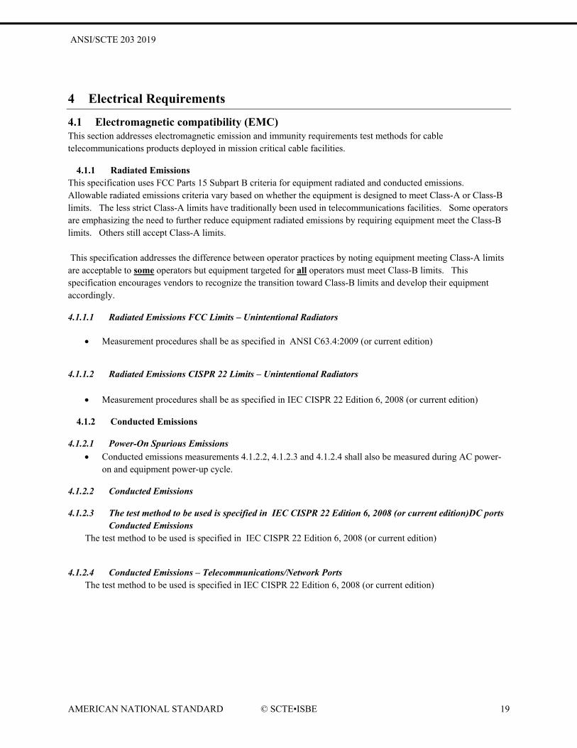
4.1.1 Radiated Emissions This specification uses FCC Parts 15 Subpart B criteria for equipment radiated and conducted emissions. Allowable radiated emissions criteria vary based on whether the equipment is designed to meet Class-A or Class-B limits. The less strict Class-A limits have traditionally been used in telecommunications facilities. Some operators are emphasizing the need to further reduce equipment radiated emissions by requiring equipment meet the Class-B limits. Others still accept Class-A limits. This specification addresses the difference between operator practices by noting equipment meeting Class-A limits are acceptable to some operators but equipment targeted for all operators must meet Class-B limits. This specification encourages vendors to recognize the transition toward Class-B limits and develop their equipment accordingly.
4.1.1.1 Radiated Emissions FCC Limits – Unintentional Radiators
• Measurement procedures shall be as specified in ANSI C63.4:2009 (or current edition)
4.1.1.2 Radiated Emissions CISPR 22 Limits – Unintentional Radiators
• Measurement procedures shall be as specified in IEC CISPR 22 Edition 6, 2008 (or current edition)
4.1.2 Conducted Emissions
4.1.2.1 Power-On Spurious Emissions • Conducted emissions measurements 4.1.2.2, 4.1.2.3 and 4.1.2.4 shall also be measured during AC power-
on and equipment power-up cycle.
4.1.2.2 Conducted Emissions
4.1.2.3 The test method to be used is specified in IEC CISPR 22 Edition 6, 2008 (or current edition)DC ports Conducted Emissions
The test method to be used is specified in IEC CISPR 22 Edition 6, 2008 (or current edition)
4.1.2.4 Conducted Emissions – Telecommunications/Network Ports The test method to be used is specified in IEC CISPR 22 Edition 6, 2008 (or current edition)

ANSI/SCTE 203 2019
AMERICAN NATIONAL STANDARD © SCTE•ISBE 20
4.1.3 Immunity Criteria
4.1.3.1 Enclosure
4.1.3.1.1 Radiated Immunity Equipment shall be tested for continuous radiated immunity as specified in IEC 61000-4-3, Ed 3.2, 2010-04; Electromagnetic Compatibility (EMC) – Part 4-3: Testing and measurement techniques – radiated, radio-frequency, electromagnetic field immunity test
4.1.3.1.2 Electrostatic Discharge (ESD)
1. Electrostatic discharge tests shall be executed according to clauses 7 and 8 of IEC 61000-4-2, Edition 1.2, 2001-04; Electromagnetic Compatibility (EMC) – Part 4-2. Positive and negative polarity voltage tests are required.
2. Tests shall be performed on all accessible equipment points accessible when the equipment is operating, is being installed, or while under maintenance.
3. Contact discharge method tests shall be applied to conductive surfaces and conductive planes. Air discharge method tests shall be applied to insulating surfaces.
4. Test points for both normal operating, storage, and maintenance type ESD testing shall be selected based on recommendations in IEC 61000-4-2, Clause 8.
4.1.3.2 AC Power Port
4.1.3.2.1 Conducted RF Immunity – AC Power Port The AC power port continuous conducted immunity test shall be implemented as specified in IEC 61000-4-6 ed 3.0, 2008; Electromagnetic Compatibility (EMC) – Part 4-6: Testing and Measurement Techniques-Immunity to Conducted Disturbances, Induced by Radio Frequency Fields
4.1.3.2.2 Surge Immunity – AC Power Port The AC power port surge immunity test shall be implemented in accordance with IEC 61000-4-5.
4.1.3.2.3 Electronic Fast Transients – AC Power Port Electrical Fast Transient testing is to be performed according to IEC 61000-4-4, Second Edition, 2004-07; Electromagnetic Compatibility (EMC) – Part 4-4: Testing and measurement techniques – Electrical fast transient/burst immunity test
4.1.3.2.4 Voltage Dips – AC Power Port IEC 61000-4-11, Second Edition, 2004-03; Electromagnetic Compatibility (EMC) – Part 4-11 shall be used to test compliance with SCTE 186 AC power port immunity to voltage dips.
4.1.3.2.5 Voltage Interruptions – AC Power Port IEC 61000-4-11, Second Edition, 2004-03; Electromagnetic Compatibility (EMC) – Part 4-11 shall be used to test compliance with SCTE 186 AC power port immunity to voltage interruptions.
4.1.3.3 DC Power Port
4.1.3.3.1 Conducted RF Immunity – DC Power Port IEC 61000-4-6 ed 3.0, 2008; Electromagnetic Compatibility (EMC) – Part 4-6: Testing and Measurement Techniques-Immunity to Conducted Disturbances, Induced by Radio Frequency Fields shall be used to test compliance with SCTE 186 DC power port conducted RF immunity.
ANSI/SCTE 203 2019
AMERICAN NATIONAL STANDARD © SCTE•ISBE 21
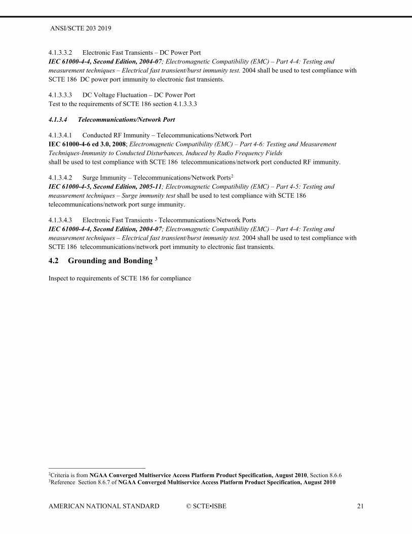
4.1.3.3.2 Electronic Fast Transients – DC Power Port IEC 61000-4-4, Second Edition, 2004-07; Electromagnetic Compatibility (EMC) – Part 4-4: Testing and measurement techniques – Electrical fast transient/burst immunity test. 2004 shall be used to test compliance with SCTE 186 DC power port immunity to electronic fast transients.
4.1.3.3.3 DC Voltage Fluctuation – DC Power Port Test to the requirements of SCTE 186 section 4.1.3.3.3
4.1.3.4 Telecommunications/Network Port
4.1.3.4.1 Conducted RF Immunity – Telecommunications/Network Port IEC 61000-4-6 ed 3.0, 2008; Electromagnetic Compatibility (EMC) – Part 4-6: Testing and Measurement Techniques-Immunity to Conducted Disturbances, Induced by Radio Frequency Fields shall be used to test compliance with SCTE 186 telecommunications/network port conducted RF immunity.
4.1.3.4.2 Surge Immunity – Telecommunications/Network Ports2 IEC 61000-4-5, Second Edition, 2005-11; Electromagnetic Compatibility (EMC) – Part 4-5: Testing and measurement techniques – Surge immunity test shall be used to test compliance with SCTE 186 telecommunications/network port surge immunity.
4.1.3.4.3 Electronic Fast Transients - Telecommunications/Network Ports IEC 61000-4-4, Second Edition, 2004-07; Electromagnetic Compatibility (EMC) – Part 4-4: Testing and measurement techniques – Electrical fast transient/burst immunity test. 2004 shall be used to test compliance with SCTE 186 telecommunications/network port immunity to electronic fast transients.
4.2 Grounding and Bonding 3 Inspect to requirements of SCTE 186 for compliance
2Criteria is from NGAA Converged Multiservice Access Platform Product Specification, August 2010, Section 8.6.6 3Reference Section 8.6.7 of NGAA Converged Multiservice Access Platform Product Specification, August 2010

ANSI/SCTE 203 2019
AMERICAN NATIONAL STANDARD © SCTE•ISBE 22
5 Sustainability Requirements
5.1 Product Development No need for test procedures for this section and its sub-sections.
5.1.1 Life Cycle Thinking4
5.1.2 Material Efficiency
5.1.3 Energy Efficiency
5.1.4 Consumables and Batteries
5.2 Product Operation No need to define tests here as test would be product specific.
5.2.1 Airflow
5.2.2 Air filters
5.2.3 Heat Release
5.2.4 Energy Efficiency
5.2.4.1 General Requirements for Equipment Energy Efficiency 1. Equipment shall measure and report energy/internal power supply efficiency in accordance with Generalized
Test Protocol for Calculating the Energy Efficiency of Internal AC-DC and DC-DC Power Supplies, Revison 6.5.
2. Equipment AC-to-DC power supply performance shall be characterized in accordance with ANSI/SCTE 46 2007, Test Methods for AC to DC Power Supplies.
3. Equipment DC-to-DC power supply performance shall be characterized in accordance with ANSI/SCTE 46 2007, Test Methods for AC to DC Power Supplies, modified as needed to cover DC rather than AC input.5
4. Equipment providers shall identify the specific energy modes in which the product operates and shall document the energy consumption for each operating mode.
5.2.4.2 Computer Energy Efficiency
5.2.4.3 Computer Server Energy Efficiency
4Includes information from ECMA-341, 4th edition December 2010, Environmental Design Consideration for ICT and CE Products, Section 5: Life Cycle Thinking and Section 4: Terms and Definitions 5 NGAA Converged Multiservice Access Platform Product Specification, August 2010, section 8.6.4

ANSI/SCTE 203 2019
AMERICAN NATIONAL STANDARD © SCTE•ISBE 23
5.2.4.3.1 ATIS Server TEER6
5.2.4.4 Transport Equipment Energy Efficiency
5.2.4.4.1 ATIS Transport TEER7
5.2.4.5 Router and Ethernet Switch Efficiency
5.2.4.5.1 ATIS Router and Ethernet Switch TEER8
5.2.5 Emissions
5.2.5.1 Chemical Emission
5.2.5.2 Acoustic emissions Reference ATIS-0600005.2006 for test methods.
5.3 Product Lifetime No need for test method.
5.4 Product Disposal No need for test method.
6 Reference ATIS 060015.01.2009, Energy Efficiency for Telecommunication Equipment: Methodology for Measurement and Reporting - Server Requirements for complete details to calculate, test, and report server TEER. 7 Reference ATIS 0600015.02.2009, Energy Efficiency for Telecommunication Equipment: Methodology for Measurement and Reporting - Transport Requirements for complete details to calculate, test and report transport equipment TEER 8 Reference ATIS 0600014.03; 2009, Energy Efficiency for Telecommunication Equipment: Methodology for Measurement and Reporting for Router and Ethernet Switch Products for complete details to calculate, test, and report Router and Ethernet Switch TEER

ANSI/SCTE 203 2019
AMERICAN NATIONAL STANDARD © SCTE•ISBE 24
6 Quality Requirements
6.1 Reliability No test methods needed.
6.2 Highly Accelerated Life Testing (HALT) No way to define this as it would be product specific.

ANSI/SCTE 203 2019
AMERICAN NATIONAL STANDARD © SCTE•ISBE 25
Appendix A – Normative References ANS01. ANSI T1.336-2009: Engineering Requirements for a Universal Telecom Framework. 2009. ANS02. ANSI/UL60950-1-2007, “Information Technology Equipment-Safety-Part2: General Requirements. 2007 ANS05. ANSI/EIA-310-D-1992: Cabinets, Racks, Panels, and Associated Equipment. 1992. ANS06. ANSI Z136-2007 American National Standard for Safe Use of Lasers. 2007 ANS08. ANSI T1.319-2002; Equipment Assemblies – Fire Propagation Risk Assessment Criteria. 2002. ANS09. ANSI T1.307-2003: Fire Resistance Criteria – Ignitability Requirements for Equipment Assemblies, Ancillary Non-Metallic Apparatus, and Fire Spread Requirements for Wire and Cable. 2003. ANS10. ANSI/'SCTE 158 2009, Recommended Environmental Condition Ranges for Broadband Communications Equipment. 2009. ANS12. ANSI C63.4-2003, American National Standard Methods for Measurement of Radio-Noise Emissions for Low-Voltage Electrical and Electric Equipment in the Range of 9 kHz to 40 GHz. 2003. ANS13.ANSI/SCTE 46 2007, Test Methods for AC to DC Power Supplies ASH02. ASHRAE, 2004, ISBN 1-931862-43-5, Thermal Guidelines for Data Processing Environments. 2004. ASH03. ASHRAE, 2005, ISBN 1-931862-94-X. Design Considerations for Datacom Equipment Centers. 2005. ATI03. ATIS 0600329, Edition 8 2008, Network Equipment - Earthquake Resistance. 2008. ATI04. ATIS 060015: 2009, Energy Efficiency for Telecommunication Equipment: Methodology for Measurement and Reporting - General Requirements. 2009. ATI05. ATIS 060015.01.2009, Energy Efficiency for Telecommunication Equipment: Methodology for Measurement and Reporting - Server Requirements. 2009. ATI06. ATIS 0600015.02.2009, Energy Efficiency for Telecommunication Equipment: Methodology for Measurement and Reporting - Transport Requirements. 2009. ATI07. ATIS 0600014.03; 2009, Energy Efficiency for Telecommunication Equipment: Methodology for Measurement and Reporting for Router and Ethernet Switch Products. 2009. ATI08. ATIS 0600015.04.2010, Energy Efficiency for Telecommunication Equipment: Methodology for Measurement and Reporting DC Power Plant – Rectifier Requirements. ATI09. ATIS-0600319.2008, Equipment Assemblies -- Fire Propagation Risk Assessment Criteria. 2008. ATI10. ATIS-0600307.2007, Fire Resistance Criteria – Ignitability requirements for Equipment Assemblies, Ancillary Non-Metallic Apparatus, and Fire Spread Requirements for Wire and Cable distribution assemblies. 2007. ATI11. ATIS-0600005.2006, Acoustic Noise. 2006. ATI12. ATI13. ATIS-060004.2006, Equipment Surface Temperature CFR01. 21CFR910; “OCCUPATIONAL SAFETY AND HEALTH STANDARDS”, Code of Federal Regulations, Title 29-Labor, Chapter XVII-Occupational Safety and Health Administrations, Department of Labor, Part 1920, 21CFR1910. CFR02. 21CFG1040;“PERFORMANCE STANDARDS FOR LIGHT EMITTING PRODUCTS”, Code of Federal Regulations, Title 21—Food and Drugs, Chapter 1-Food and Drug Administration, Department of Health and Human Services, Subchapter J-Radiological Health, Part 1040, 21CFG1040.10. CFR03. 29 CFR1910.05; “Occupational Noise Exposure”, Code of Federal Regulations, Title 29, Part 1910, Subpart 95 (1910.95), U.S. Department of Labor, Occupational Saftey and Health Administration (OSHA), 29 CFR1910.05. CFR04. 47CFR15; “RADIO FREQUENCY DEVICES”, --Telecommunication, Chapter 1-Federal Communications Commission, Part 15-Radio Frequency Device, 47CFR15. EC1. (noise) DIRECTIVE 2003/10/EC OF THE EUROPEAN PARLIAMENT AND OF THE COUNCIL of February, 2003 on the minimum heath and safety requirements regarding the exposure of workers to the risks arising from physical agents. 2003.

ANSI/SCTE 203 2019
AMERICAN NATIONAL STANDARD © SCTE•ISBE 26
EC2. (RoHS) DIRECTIVE 2002/95/EC OF THE EUROPEAN PARLIAMENT AND OF THE COUNCIL of 27 January 2003 on the restriction of the use of certain hazardous Substances in electrical and electronic equipment (and latest associated amendments). 2002. EC3. (WEEE) DIRECTIVE 2002/96/EC OF THE EUROPEAN PARLIAMENT AND OF THE COUNCIL of 27 January 2003 on waste electrical and electronic equipment (WEEE) (and latest associated amendments). 2002. ECMA01. ECMA-109, December 2010; Declared Noise Emission Values of Information Technology and Telecommunications Equipment, 5th edition (December 2010). ECMA, 2010. ECMA02. ECMA-341:2010, “Environmental Design Considerations for ICT & CE Products.”. 2010. ECMA03. ECMA-74 Measurement of Airborne Noise Emiitted by Informatin Techology and Telecommunications Equipment. ECMA04. ECMA-341, 4th edition December 2010, Environmental Design Consideration for ICT and CE Products ECMA05, ECMA-370, 4th Edition June 2009, TED-The Echo Declaration EPRI01. Generalized Test Protocol for Calculating the Energy Efficiency of Internal AC-DC and DC-DC Power Supplies, Revison 6.5. ESTAR01. ENERGY STAR® Program Requirments for Computers Version 5.0. 2008. ESTAR02. ENERGY STAR® Version 1.0 Program Requirements for Computer Servers. 2009. ESTAR03. ENERGY STAR® Program Requirements Product Specification for Uninterruptible Power Supplies (UPSs), Draft 1 Version 1.0. 2011. ESTAR04.ENERGY STAR® Version 2.0, Draft 1 Program Requirements for Computer Servers ETS01. EN 300 119-1, V2.1.1 (2004-2009) , Environmental Engineering (EE); European telecommunications standard for equipment practice; Part 1: Introduction and terminology, ETSI EN 300 119-1, V2.1.1, 2004-09. 2004-2009. ETS02. EN 300 119-2, V2.1.1, 2004-09; Environmental Engineering (EE); European telecommunications standard for equipment practice; Part 2: Engineering requirements for racks and cabinets. 2004-09. ETS03. EN 300 119-3, V2.1.1, 2004-09; Environmental Engineering (EE); European telecommunications standard for equipment practice; Part 3: Engineering requirements for miscellaneous racks and cabinets, ETSI. 2004-09. ETS05. EN 300 119-5, V1.2.2, 2004-12; Environmental Engineering (EE); European telecommunications standard for equipment practice; Part 5: Thermal Management, ETSI. 2004-12. ETS06. TR 102 489, V1.1.1, 2004-06; Environmental Engineering (EE); European telecommunications standard for equipment practice; Thermal Management Guidance for equipment and its deployment, ETSI. 2004-06. ETS07. ETR 035, July 1999; Equipment Engineering (EE); Environmental Engineering; Guidance and Terminology, ETSI 2. 1999. ETS08. EN 300 019-1-0, V 2.1.2,2003-09; Environmental Engineering (EE); Environmental conditions and environmental tests for telecommunications equipment; Part 1-0: Classification of environmental conditions; Introduction, ETSI. 2003-09. ETS09. EN 300-019-1-1 V2.1.4 (2003-2004); Equipment Engineering (EE); Environmental conditions and environmental tests for telecommunications equipment, Part 1-1: Classification of environmental conditions; Storage, ETSI EN 300-019-1-1, V2.1.4, ETSI, 2003-04. 2003-04. ETS10. ETSI EN 300-019-1-2, V2.1.4, 2003-04; Equipment Engineering (EE); Environmental conditions and environmental tests for telecommunications equipment, Part 1-2: Classification of environmental conditions; Transportation, ETSI. 2003-04. ETS11. ETSI EN 300 019-1-3, v2.3.2, (2009-11) Environmental Engineering (EE); Environmental conditions and environmental tests for telecommunications equipment; Part 1-3: Classification of environmental conditions; Stationary use at weatherprotected locations, ETSI. ETSI, 2009-11. ETS12. EN 300 019-2-0, V 2.1.2, 2003-09; Environmental Engineering (EE); Environmental conditions and environmental tests for telecommunications equipment; Part 2-0: Specification of environmental tests; Introduction, ETSI. 2003-09.

ANSI/SCTE 203 2019
AMERICAN NATIONAL STANDARD © SCTE•ISBE 27
ETS13. EN 300 019-2-1, V 2.1.2, ETSI, 2000-09; Environmental Engineering (EE); Environmental conditions and environmental tests for telecommunications equipment; Part 2-1: Specification of environmental tests; Storage, ETSI. 2000-09. ETS14. EN 300 019-2-2, V 2.1.2, 1999-09; Environmental Engineering (EE); Environmental conditions and environmental tests for telecommunications equipment; Part 2-2: Specification of environmental tests; Transportation. 1999-09. ETS15. EN 300 019-2-3, V 2.2.2, 2003-04; Environmental Engineering (EE); Environmental conditions and environmental tests for telecommunications equipment; Part 2-3: Specification of environmental tests; Stationary use at weatherprotected locations, ETSI. 2003-04. ETS16. ETS 300 753, October 1997; Equipment Engineering (EE); Acoustic noise emitted by telecommunications equipment, ETSI. 1997. ETS17. EN 300 132-1, September 1996; Environmental Engineering (EE); Power supply interface at the input to telecommunications equipment; Part 1: Operated by alternating current (ac) derived from direct current (dc) sources, ETSI. 1996 ETS21. EN 300 386, V1.3.3 (2010-10); Electromagnetic Compatibility and Radio Spectrum Matters (ERM); Telecommunications Network Equipment; ElectroMagnetic Compatibility (EMC) Requirements. 2010. ETS22. ETSI ES 201 468 V1.3.1, 2005-08; Additional Electromagnetic Compatibility (EMC) requirements and resistibility requirements for telecommunications equipment for enhanced availability of service in specific applications, ETSI. 2005-08. ETS23. ETR 127, ETSI, March 1994; Equipment Engineering (EE); Electrostatic environment and mitigation measures for Public Telecommunications Network (PTN), ETSI. 1994. FCC01. 47eCFR15, Electronic Code of Federal Regulations (e-CFR), Title 47: Telecommunication, Part 15 – Radio Frequency Devices. FCC02. 47eCFR68, Electronic Code of Federal Regulations (e-CFR), Title 47: Telecommunication, Part 68 – Connection of Terminal Equipment to the Telephone Network. IEC01. IEC 60951-1 2nd edition, 2005-12; Safety of information technology equipment including electrical business equipment. 2005-12. IEC02. IEC 60825-1 ed2.0, 2007; Safety of laser products - Part 1: Equipment classification and requirements. 2007. IEC03. IEC 61000-4-6 ed 3.0, 2008; Electromagnetic Compatibility (EMC) – Part 4-6: Testing and Measurement Techniques-Immunity to Conducted Disturbances, Induced by Radio Frequency Fields IEC04. IEC 61000-3-2, Third Edition, 2005-11; Electromagnetic Compatibility (EMC) – Part 3-2: Limits – Limits for harmonic current emissions (equipment input current <=16A per phase),. 2005-11. IEC05. IEC 61000-3-3, ed 2.0, 2008; (EMC) – Part 3-3: Limits – Limitation of voltage changes, voltage fluctuations and flicker in public low-voltage supply systems, for equipment with rated current <=16A per phase and not subject to conditional connection, IEC. 2008. IEC06. IEC 61000-4-2, Edition 1.2, 2001-04; Electromagnetic Compatibility (EMC) – Part 4-2: Testing and measurement techniques – Electrostatic discharge immunity test,. 2001-04. IEC07. IEC 61000-4-8, Edition 1.1, 2001-03; Electromagnetic Compatibility (EMC) – Part 4-8: Testing and measurement techniques – Power frequency magnetic field immunity test,. 2001-03. IEC08. IEC 61000-4-3, Ed 3.2, 2010-04; Electromagnetic Compatibility (EMC) – Part 4-3: Testing and measurement techniques – radiated, radio-frequency, electromagnetic field immunity test. 2010. IEC09. IEC 61000-4-4, Second Edition, 2004-07; Electromagnetic Compatibility (EMC) – Part 4-4: Testing and measurement techniques – Electrical fast transient/burst immunity test. 2004. IEC10. IEC 61000-4-5, Second Edition, 2005-11; Electromagnetic Compatibility (EMC) – Part 4-5: Testing and measurement techniques – Surge immunity test. 2005. IEC11. IEC 61000-4-6, Edition 2.2, 2006-05; Electromagnetic Compatibility (EMC) – Part 4-6: Testing and measurement techniques – Immunity to conducted disturbances, induced by radio-frequency fields. 2006.

ANSI/SCTE 203 2019
AMERICAN NATIONAL STANDARD © SCTE•ISBE 28
IEC12. IEC 61000-4-11, Second Edition, 2004-03; Electromagnetic Compatibility (EMC) – Part 4-11: Testing and measurement techniques – Voltage dips, short interruptions and voltage variations immunity tests. 2004. IEC13. IEC 60068-2-2: "Environmental testing - Part 2: Tests" IEC14. IEC 60271-3-3, 2002; Classification of environmental parameters and their severities - Stationary use of weather-protected locations. 2002. IEC15. IEC CISPR 22 Edition 6.0 2008-09; International Technology Equipment - Radio Disturbance Characteristics - Limits and Methods of Measurement. 2008. IEC16. IEC CISPR 24, Edition 2.0 2010; Information Technology Equipment - Immunity Characteristics - Limit and Methods of Measurement. 2010. IEC17. ETS 300 753 October 1997; Equipment Engineering (EE); Acoustic noise emitted by telecommunications equipment. ETSI. 1997. IEC18. ISO/IEC DIS 2836, Edition 11 January 2011; Information Technology – Office Equipment – Determination of Chemical Emission Rates from Electronic Equipment SCO5. Environmental Profile: Central Offices and Network Data Centers, Version 1.0 May 5, 2008. Environmental Profile. MSO01.NGAA Converged Multiservice Access Platform Product Specification, August 2010, Hardware & Functional Specification, August 2, 2010 SCTE 184, Facilities Energy Managment and Recommended Practices 2012. 2012. TEL06. SR-332 Issue 1, May 2001; Reliability Prediction Procedure for Electrical Equipment, Telcordia. 2001. TEL08. SR-332 Issue 2, September 2006; Reliability Prediction Procedure for Electrical Equipment, , Telcordia. 2006.

ANSI/SCTE 203 2019
AMERICAN NATIONAL STANDARD © SCTE•ISBE 29
Appendix B – Informative References ANS03. ATIS-PP-0600315.2007: Voltage Levels for DC-Powered Equipment Used in the Telecommunications Environment. 2007. ANS04. ANSI/TIA -42-2005: Telecommunications Infrastructure Standard for Network Data Center. 2005. ANS11. ANSI/TIA-968-A-2002, Telecommunications - Telephone Terminal Equipment – Technical Requirements for Connection of Terminal Equipment to the Telephone Network. 2002. ASH01. ASHRAE, 2005 ISBN 1-931862-65-6. 2005.Datacom Equipment Power Trends and Cooling Applications, ASH03. ASHRAE, 2005, ISBN 1-931862-94-X. Design Considerations for Datacom Equipment Centers. 2005. ASH04. ASHRAE, 2006, ISBN-10: 1-933742-05, Liquid Cooling Guidelines for Datacom Equipment Centers. 2006. ASH05. ASHRAE, 2007, ISBN:987-1-933742-20-5, Structural and Vibration Guidelines for Datacom Equipment Centers. 2007. EC4. DIRECTIVE 2006/95/EC OF THE EUROPEAN PARLIAMENT AND OF THE COUNCIL of 12 December 2006 on the harmonization of the laws of Member States relating to electrical equipment designed for use within certain voltage limits (and 2008/C 28/01 for harmonized stand. 2006. EC5. (EMC) DIRECTIVE 2004/108/EC OF THE EUROPEAN PARLIAMENT AND OF THE COUNCIL of 15 December 2004 on the approximation of the laws of the Member States relating to electromagnetic compatibility. 2004. EN01. “Information technology equipment including electrical business equipment”, European Norm, European Committee for Electrotechnical Standardsization (CENELEC). ENE1. Usage and Public Reporting Guidelines for PUE/DCiE – WP #22. ENE2. Recommendations for Measuring and Report Overall Data Center Efficiency. ETS04. EN 300 119-4, V2.1.1, 2004-09; Environmental Engineering (EE); European telecommunications standard for equipment practice; Part 4: Engineering requirements for subracks in miscellaneous racks and cabinets, ETSI. 2004-09. ETS18. Draft ETSI EN 300 132-2, V2.3.6 (2011-12); Power supply interface at the input to the telecommunications and datacom (ICT) equipment; Part 2: Operated by -48V direct current. 2011-12. ETS19. ETSI EN 300 132-3, V1.2.1, 2003-08; Environmental Engineering (EE); Power supply interface at the input to telecommunications equipment; Part 3: Operated by rectified current source, alternating current source or direct current source up to 400V, ETSI. 2003-08. ETS20. EN 300 253, V2.1.1, ETSI 2002-04; Equipment Engineering (EE); Earthing and bonding of telecommunications equipment in telecommunication centres, ETSI. 2003-04. SCO1. SCOPE AdvancedTCA™ HW Profile, latest version . SCO2. SCOPE MicroTCA™ HW Profile, latest version . SCO3. SCOPE Services and Support Profile – Service Availability, latest version . SCO4. SCOPE Services and Support Profile – Long Life Cycle Support, latest version . TEL01. GR-63-CORE, Issue 3, March 2006; NEBS Requirements: Physical Protection, GR-63-CORE, Issue 3, March 2006, Telcordia. 2006. TEL02. GR-3028-CORE, Issue 1, December 2001; Thermal Management in Telecommunications Central Offices, Telcordia. 2001. TEL03. GR-1089-Core, Issue 5, August 2009; Electromagnetic Compatibility and Electrical Safety –Generic Criteria for Network Telecommunications Equipment, Telcordia. 2009. TEL04. GR-78-CORE, Issue 2, September 2007; Generic Requirements for the Physical Design and Manufacture of Telecommunications Products and Equipment. 2007. TEL05. FR-2063, NEBS Criteria Levels, A module of NEBSFR,Telcordia Technologies Special Report, SR-3580, Issue 3, June 2007, Telcordia.

ANSI/SCTE 203 2019
AMERICAN NATIONAL STANDARD © SCTE•ISBE 30
TEL09. GR-2914-CORE, Issue 4, December 1998; Human Factors Requirements for Equipment to Improve Network Reliability, , Bellcore. 1998. TEL10. GR-485-CORE, Issue 5, April 2004; Common Language Equipment Codes (CLEI Codes) – Generic Requirements for Processes and Guidelines,. 2004. TEL11. GR-383, Issue 3, February 2006; Common Language Equipment Codes (CLEI Codes) – Generic Requirements for Product Labels,. 2006. TEL12. GR-1502-CORE, Issue 5, December 2006; Central Office / Network Environment Detail Engineering Generic Requirements,. 2006. TEL13. GR-295, Issue 1, November 2004; Mesh and Isolated Bonding Networks: Definition and Application to Telephone Central Offices. 2004. TEL14. GR-1275-CORE, Issue 8, December 2006; Central Office/Network Environment Equipment Installation / Removal Generic Requirements. 2006. TIA02. TIA-569-B, 2004; Commercial Building Standard for Telecommunications Pathways and Spaces. 2004.
Related Documents

![ANSI/SCTE 130-9 2014 130-9 2014.pdfANSI/SCTE 130-9 2014 Recommended Practices for SCTE 130 Digital Program Insertion—Advertising Systems Interfaces . ii NOTICE ... [SCTE130-3 2013]](https://static.cupdf.com/doc/110x72/5e960b0de4d9454fe70050af/ansiscte-130-9-2014-130-9-2014pdf-ansiscte-130-9-2014-recommended-practices-for.jpg)


![Data-Over-Cable Service Interface Specifications 137-3 2010... · 2018-05-25 · [ERMI] SCTE 137-4 2010, Edge Resource Manager Interface. [OSSI2.0] ANSI/SCTE 79-2 2009, DOCSIS 2.0](https://static.cupdf.com/doc/110x72/5b25d3e77f8b9aa33d8b463b/data-over-cable-service-interface-137-3-2010-2018-05-25-ermi-scte-137-4.jpg)


