Document No.: M-W3656AE-6.0 ANRITSU CORPORATION ● For safety and warning information, please read this manual before attempting to use the equipment. ● Additional safety and warning information is provided within the “MS2690A/MS2691A/MS2692A and MS2830A/MS2840A/MS2850A Signal Analyzer Operation Manual (Noise Figure Measurement Function Operation)”. Please also refer to this document before using the equipment. ● Keep this manual with the equipment. MS2690A/MS2691A/MS2692A and MS2830A/MS2840A/MS2850A Signal Analyzer Operation Manual Noise Figure Measurement Function Remote Control Sixth Edition

Welcome message from author
This document is posted to help you gain knowledge. Please leave a comment to let me know what you think about it! Share it to your friends and learn new things together.
Transcript

Document No.: M-W3656AE-6.0
ANRITSU CORPORATION
● For safety and warning information, please read this
manual before attempting to use the equipment.
● Additional safety and warning information is provided
within the “MS2690A/MS2691A/MS2692A and
MS2830A/MS2840A/MS2850A Signal Analyzer
Operation Manual (Noise Figure Measurement
Function Operation)”. Please also refer to this
document before using the equipment.
● Keep this manual with the equipment.
MS2690A/MS2691A/MS2692A and MS2830A/MS2840A/MS2850A
Signal Analyzer Operation Manual
Noise Figure Measurement Function
Remote Control
Sixth Edition

ii
Safety Symbols
To prevent the risk of personal injury or loss related to equipment malfunction, Anritsu Corporation uses the
following safety symbols to indicate safety-related information. Ensure that you clearly understand the meanings of
the symbols BEFORE using the equipment. Some or all of the following symbols may be used on all Anritsu
equipment. In addition, there may be other labels attached to products that are not shown in the diagrams in this
manual.
Symbols used in manual This indicates a very dangerous procedure that could result in serious injury or death if not performed properly.
This indicates a hazardous procedure that could result in serious injury or death if not performed properly. This indicates a hazardous procedure or danger that could result in light-to-severe injury, or loss related to equipment malfunction, if proper precautions are not taken.
Safety Symbols Used on Equipment and in Manual The following safety symbols are used inside or on the equipment near operation locations to provide information
about safety items and operation precautions. Ensure that you clearly understand the meanings of the symbols and
take the necessary precautions BEFORE using the equipment.
This indicates a prohibited operation. The prohibited operation is indicated symbolically in or near the barred circle.
This indicates an obligatory safety precaution. The obligatory operation is
indicated symbolically in or near the circle. This indicates a warning or caution. The contents are indicated symbolically in or
near the triangle. This indicates a note. The contents are described in the box. These indicate that the marked part should be recycled.
MS2690A/MS2691A/MS2692A and MS2830A/MS2840A/MS2850A Signal Analyzer Operation Manual Noise Figure Measurement Function Remote Control 23 October 2012 (First Edition) 28 April 2017 (Sixth Edition) Copyright © 2012-2017, ANRITSU CORPORATION. All rights reserved. No part of this manual may be reproduced without the prior written permission of the publisher. The contents of this manual may be changed without prior notice. Printed in Japan
DANGER
WARNING
CAUTION

iii
Notes On Export Management This product and its manuals may require an Export License/Approval by
the Government of the product's country of origin for re-export from your
country.
Before re-exporting the product or manuals, please contact us to confirm
whether they are export-controlled items or not.
When you dispose of export-controlled items, the products/manuals need
to be broken/shredded so as not to be unlawfully used for military purpose.

iv

I
About This Manual Associated Documents
The operation manual configuration of the MS2690A/MS2691A/MS2692A, MS2830A, MS2840A, and MS2850A Signal Analyzer is shown below.
MS2690A/MS2691A/MS2692A and MS2830A/MS2840A/MS2850A Signal Analyzer Operation Manual (Noise Figure Measurement Function Operation)
MS2690A/MS2691A/MS2692A and MS2830A/MS2840A/MS2850A Signal Analyzer Operation Manual (Noise Figure Measurement Function Remote Control)
MS2690A/MS2691A/MS2692A Signal Analyzer Operation Manual (Main Frame Operation)
MS2690A/MS2691A/MS2692A and MS2830A/MS2840A/MS2850A Signal Analyzer Operation Manual (Main Frame Remote Control)
MS2840A Signal Analyzer Operation Manual (Main Frame Operation) Or
MS2830A Signal Analyzer Operation Manual (Main Frame Operation)
MS2850A Signal Analyzer Operation Manual (Main Frame Operation)
MS2690A/MS2691A/MS2692A Signal Analyzer Operation Manual (Signal Analyzer Function Operation)
MS2690A/MS2691A/MS2692A and MS2830A/MS2840A/MS2850A Signal Analyzer Operation Manual (Signal Analyzer Function Remote Control)
MS2830A/MS2840A/MS2850A Signal Analyzer Operation Manual (Signal Analyzer Function Operation)
Or
MS2690A/MS2691A/MS2692A Spectrum Analyzer Operation Manual (Spectrum Analyzer Function Operation)
MS2690A/MS2691A/MS2692A and MS2830A/MS2840A/MS2850A Signal Analyzer Operation Manual (Spectrum Analyzer Function Remote Control)
MS2830A/MS2840A/MS2850A Spectrum Analyzer Operation Manual (Spectrum Analyzer Function Operation)
Or

II
● Signal Analyzer Operation Manual (Mainframe Operation)
● Signal Analyzer Operation Manual (Mainframe Remote Control)
Description of basic operations, maintenance procedures, common functions and common remote functions of the mainframe
● Signal Analyzer Operation Manual (Signal Analyzer Function)
● Signal Analyzer Operation Manual (Signal Analyzer Function Remote
Control)
Description of basic operations, functions and remote functions of the signal analyzer
● Signal Analyzer Operation Manual (Spectrum Analyzer Function)
● Signal Analyzer Operation Manual (Spectrum Analyzer Function Remote
Control)
Description of basic operations, functions and remote functions of the spectrum analyzer
● Signal Analyzer Operation Manual (Noise Figure Measurement Function)
● Signal Analyzer Operation Manual (Noise Figure Measurement Function
Remote Control) <This document>
Description of basic operations, functions and remote functions of the Phase
Noise

III
3
2
1 Table of Contents
About This Manual ........................................ I
Chapter 1 Overview .................................... 1-1
1.1 Overview ....................................................................... 1-2
1.2 Native Mode .................................................................. 1-4
1.3 Setting Numeric Program Data ..................................... 1-7
Chapter 2 SCPI Device Message Details .. 2-1
2.1 Selecting Application .................................................... 2-6
2.2 Setting Frequency / Span ........................................... 2-12
2.3 Setting Level ............................................................... 2-30
2.4 Setting RBW • Average ............................................... 2-40
2.5 Marker ......................................................................... 2-48
2.6 Setting Signal Search ................................................. 2-60
2.7 Trace ........................................................................... 2-65
2.8 Calibration Setting ...................................................... 2-70
2.9 Setting Correction ....................................................... 2-78
2.10 Setting DUT mode .................................................... 2-102
2.11 Execute measurement and query results ................. 2-104
2.12 Save / Load Files ...................................................... 2-117
2.13 Setting Convert ......................................................... 2-123
2.14 Setting External LO ................................................... 2-135
Chapter 3 SCPI Status Register ................ 3-1
3.1 Querying Measurement Status ..................................... 3-2
3.2 Questionable Status Register ....................................... 3-3
3.3 Operation Status:Register .......................................... 3-14
3.3 Utility ........................................................................... 3-19

IV.

Chapter 1 Overview
1-1
1
Overview
This chapter provides an overview of the remote control of the Noise Figure Measurement Function (hereinafter, referred to as “this application”).
1.1 Overview ....................................................................... 1-2 1.1.1 Interface ............................................................ 1-2 1.1.2 Controlled Application....................................... 1-3
1.2 Native Mode .................................................................. 1-4 1.3 Setting Numeric Program Data ..................................... 1-7

Chapter 1 Overview
1-2
1.1 Overview This application can be controlled from an external controller (PC) by remote control commands using the MS2690/MS2691/MS2692A, MS2830A, MS2840A, or MS2850A Signal Analyzer (hereinafter, referred to as “this instrument”). The remote control commands are defined by the SCPI format.
1.1.1 Interface This instrument has GPIB, Ethernet, and USB interfaces for remote control. Those interfaces cannot be used at the same time.
The interface is automatically determined when a command is received at the start of communication. This instrument enters the remote state after the interface has been determined. The front panel lamp lights during remote interface operation, and goes off during local-interface operation.
Refer to the MS2690A/MS2691A/MS2692A and MS2830A/MS2840A/MS2850A Signal Analyzer Operation Manual (Mainframe Remote Control) for more details of the basic operations for remote control, such as interface setting.

1.1 Overview
1-3
1
Overview
1.1.2 Controlled Application Two types of the remote control commands can be used with this instrument: commands that are commonly applied to this instrument itself or all the applications (hereinafter, referred to as “Common commands”), and the other commands unique to the applications. Common commands can be executed at any time and do not depend on the currently controlled application. However, commands unique to an application can be executed at the controlled application. If it is executed at another application, the command is not executed or an error occurs.
In this instrument, multiple applications can be activated at the same time. Only one application resource can be executed at one time per piece of hardware. This application measures an input signal by using the resource of RF Input. Thus, this application cannot be executed at the same time with another application using the same resource such as the signal analyzer function. In order to execute a function unique to the application by using the remote control, you need to select this application while it has been running. Furthermore, this application can be executed at the same time with another application that uses by itself a resource not used by this application, such as the Vector Signal Generator option.

Chapter 1 Overview
1-4
1.2 Native Mode In this instrument, the syntax/format types of the remote control commands are defined as “Language mode.” The language mode has two modes: SCPI and Native.
(1) SCPI mode The SCPI mode processes commands conforming to the syntax/format defined in SCPI (ver1999.0). For programming, you can use character strings in long/short form and can omit definition character strings within square brackets ([ ]). On the Configuration screen, the SCPI mode is automatically set after transmitting command SYST:LANG SCPI.
(2) Native mode The Native mode processes commands that are in this instrument's own definition type. Unless otherwise specified, the character string of a command header is fixed. If application commands are defined only by the SCPI mode, character strings converted according to the conversion rules are the commands in the Native mode. For programming, you cannot use the grammar of the SCPI mode, such as character strings in long/short form and cannot omit any definition character strings within square brackets ([ ]).
On the Configuration screen, the Native mode is automatically set after transmitting SYST:LANG NAT.
Note: The STATus:QUEStionable and STATus:OPERation registers cannot be used in the Native mode, even if the corresponding commands are converted to Native-mode commands according to the conversion rules.

1.2 Native Mode
1-5
1
Overview
SCPI Mode
Command definition
AAAAaa:BBBBbb[:CCCCcc]:D|E <n>
Programming examples:
AAAAaa:BBBBbb:CCCCcc:D 0
AAAA:BBBB:CCCC:D 0
AAAA:BBBB:D 0
AAAA:BBBB:CCCC:E 0
Native Mode (Initial setting)
Command definition (Original)
VWXYZ1 <n>
Programming examples:
VWXYZ 0
Command Definition (Converted
from SCPI) AAAA:BBBB:D <n>
Programming examples:
AAAA:BBBB:D 0
SYST:LANG SCPI
SYST:LANG NAT
AAAA:BBBB:E 0
Figure 1.2-1 SCPI and Native modes
This application is only defined as the SCPI mode commands. You need to follow the conversion rules below in order to control this application by using the Native mode.
Conversion Rules
[1] Move the numeric parameter in the program header of an SCPI command before the argument. Delete a numeric parameter which only has one value and can be deleted. Describe the argument if it cannot be deleted.
[2] Use the first one if multiple nodes can be selected.
[3] Delete those layers which can be deleted.
[4] Alter all long forms into short forms.
[5] Delete the colon mark (“:”) at the head.
Example
To convert :DISPlay:WINDow[1]:TRACe:Y[:SCALe]:RLEVel <real> into a Native mode command. [1] Delete a numeric parameter in the program header which only has
one value and can be deleted. :DISPlay:WINDow[1]:TRACe:Y[:SCALe]:RLEVel <real>
↓ :DISPlay:WINDow:TRACe:Y:[SCALe]:RLEVel <real>

Chapter 1 Overview
1-6
[2] Delete those layers which can be deleted. :DISPlay:WINDow:TRACe:Y[:SCALe]:RLEVel <real>
↓ :DISPlay:WINDow:TRACe:Y:RLEVel <real>
[3] Alter all long forms into short ones.
:DISPlay:WINDow:TRACe:Y:RLEVel <real>
↓ :DISP:WIND:TRAC:Y:RLEV <real>
[4] Delete the colon mark (“:”) at the head.
:DISP:WIND:TRAC:Y:RLEV <real>
↓ DISP:WIND:TRAC:Y:RLEV <real>

1.3 Setting Numeric Program Data
1-7
1
Overview
1.3 Setting Numeric Program Data The following character programs can be used for setting numeric program data (numeric parameter).
(1) DEFault
After DEFault is set to numeric program data, the target parameter is set to the initial value.
(2) MINimum
After MINimum is set to numeric program data, the target parameter is set to the minimum value.
(3) MAXimum
After MAXimum is set to numeric program data, the target parameter is set to the maximum value.

Chapter 1 Overview
1-8.

Chapter 2 SCPI Device Message Details
2-1
2
SCPI Device M
essage Details
This chapter describes the detailed specifications of SCPI remote control commands for executing the functions of this application. The device messages are listed according to each function. Refer to the MS2690A/MS2691A/MS2692A and MS2830A/MS2840A/MS2850A Signal Analyzer Operation Manual (Mainframe Remote Control) for the detailed specifications of the IEEE488.2 common device messages and application common device messages.
2.1 Selecting Application ..................................................................................................................... 2-6 :SYSTem:APPLication:LOAD NFIGURE ...................................................................................... 2-7 :SYSTem:APPLication:UNLoad NFIGURE ................................................................................... 2-7 :INSTrument[:SELect] NFIGURE|CONFIG ................................................................................... 2-8 :INSTrument[:SELect]? ................................................................................................................. 2-8 :INSTrument:SYSTem NFIGURE,[ACTive]|INACtive|MINimum ................................................... 2-9 :INSTrument:SYSTem? NFIGURE ............................................................................................. 2-10 :INSTrument:DEFault .................................................................................................................. 2-11 :SYSTem:PRESet ....................................................................................................................... 2-11
2.2 Setting Frequency / Span ............................................................................................................ 2-12 [:SENSe][:NFIGure]:FREQuency:SPAN <freq> .......................................................................... 2-13 [:SENSe][:NFIGure]:FREQuency:SPAN? ................................................................................... 2-14 [:SENSe][:NFIGure]:FREQuency:SPAN:FULL ........................................................................... 2-15 [:SENSe][:NFIGure]:FREQuency:CENTer <freq> ....................................................................... 2-16 [:SENSe][:NFIGure]:FREQuency:CENTer? ................................................................................ 2-17 [:SENSe][:NFIGure]:FREQuency:STARt <freq> ......................................................................... 2-18 [:SENSe][:NFIGure]:FREQuency:STARt?................................................................................... 2-19 [:SENSe][:NFIGure]:FREQuency:STOP <freq> .......................................................................... 2-20 [:SENSe][:NFIGure]:FREQuency:STOP? ................................................................................... 2-21 [:SENSe][:NFIGure]:SWEep:POINts <integer> ........................................................................... 2-22 [:SENSe][:NFIGure]:SWEep:POINts? ......................................................................................... 2-22 [:SENSe][:NFIGure]:FREQuency:FIXed?.................................................................................... 2-23 [:SENSe][:NFIGure]:FREQuency:LIST:DATA <freq>,([,<freq>])* ............................................... 2-24 [:SENSe][:NFIGure]:FREQuency:LIST:DATA? ........................................................................... 2-25 [:SENSe][:NFIGure]:FREQuency:LIST:COUNt? ......................................................................... 2-26 [:SENSe][:NFIGure]:FREQuency:LIST:POSition <integer> ........................................................ 2-27 [:SENSe][:NFIGure]:FREQuency:LIST:POSition? ...................................................................... 2-27 [:SENSe][:NFIGure]:FREQuency:MODE SWEPt|SWEep|FIXed|LIST ....................................... 2-28 [:SENSe][:NFIGure]:FREQuency:MODE? .................................................................................. 2-29
2.3 Setting Level ............................................................................................................................... 2-30 [:SENSe][:NFIGure]:POWer[:RF]:ATTenuation <rel_amp> ........................................................ 2-31 [:SENSe][:NFIGure]:POWer[:RF]:ATTenuation? ........................................................................ 2-32 [:SENSe][:NFIGure]:POWer[:RF]:GAIN[:STATe] OFF|ON|0|1 ................................................... 2-33 [:SENSe][:NFIGure]:POWer[:RF]:GAIN[:STATe]? ...................................................................... 2-33 :DISPlay[:NFIGure]:TRACe:Y[:SCALe]:PDIVision

Chapter 2 SCPI Device Message Details
2-2
NFIGure|NFACtor|GAIN|YFACtor|TEFFective|PHOT|PCOLd,<rel_amp> ....................... 2-34 :DISPlay[:NFIGure]:TRACe:Y[:SCALe]:PDIVision?
NFIGure|NFACtor|GAIN|YFACtor|TEFFective|PHOT|PCOLd .......................................... 2-35 :DISPlay[:NFIGure]:TRACe:NFIGure|NFACtor|GAIN|YFACtor|TEFFective|PHOT|PCOLd:Y
[:SCALe]:PDIVision <rel_amp> ......................................................................................... 2-36 :DISPlay[:NFIGure]:TRACe:NFIGure|NFACtor|GAIN|YFACtor|TEFFective|PHOT|PCOLd:Y
[:SCALe]:PDIVision? ......................................................................................................... 2-36 :DISPlay[:NFIGure]:TRACe:Y[:SCALe]:RLEVel:VALue
NFIGure|NFACtor|GAIN|YFACtor|TEFFective|PHOT|PCOLd,<level> ............................. 2-37 :DISPlay[:NFIGure]:TRACe:Y[:SCALe]:RLEVel:VALue?
NFIGure|NFACtor|GAIN|YFACtor|TEFFective|PHOT|PCOLd .......................................... 2-38 :DISPlay[:NFIGure]:TRACe:NFIGure|NFACtor|GAIN|YFACtor|TEFFective|PHOT|PCOLd:Y
[:SCALe]:RLEVel <level> .................................................................................................. 2-39 :DISPlay[:NFIGure]:TRACe:NFIGure|NFACtor|GAIN|YFACtor|TEFFective
|PHOT|PCOLd:Y[:SCALe]:RLEVel? ................................................................................. 2-39 2.4 Setting RBW • Average ............................................................................................................... 2-40
[:SENSe][:NFIGure]:AVERage[:STATe] AVERage|ON|OFF|1|0 ................................................ 2-41 [:SENSe][:NFIGure]:AVERage[:STATe]? .................................................................................... 2-41 [:SENSe][:NFIGure]:AVERage:COUNt <integer> ....................................................................... 2-42 [:SENSe][:NFIGure]:AVERage:COUNt? ..................................................................................... 2-43 [:SENSe][:NFIGure]:BWIDth|BANDwidth[:RESolution] <freq> ................................................... 2-44 [:SENSe][:NFIGure]:BWIDth|BANDwidth[:RESolution]? ............................................................. 2-44 :CALCulate:ATIMe:LENGth <time> ............................................................................................. 2-45 :CALCulate:ATIMe:LENGth? ....................................................................................................... 2-46 :CALCulate:ATIMe:AUTO ON|OFF|1|0 ....................................................................................... 2-47 :CALCulate:ATIMe:AUTO? ......................................................................................................... 2-47
2.5 Marker ......................................................................................................................................... 2-48 :CALCulate[:NFIGure]:MARKer[1]|2|3|4:MODE NORMal|DELTa|OFF ....................................... 2-49 :CALCulate[:NFIGure]:MARKer[1]|2|3|4:MODE? ........................................................................ 2-50 :CALCulate[:NFIGure]:MARKer[1]|2|3|4:REFerence <integer> .................................................. 2-51 :CALCulate[:NFIGure]:MARKer[1]|2|3|4:REFerence? ................................................................ 2-52 :CALCulate[:NFIGure]:MARKer[1]|2|3|4:X <freq> ....................................................................... 2-53 :CALCulate[:NFIGure]:MARKer[1]|2|3|4:X? ................................................................................ 2-54 :CALCulate[:NFIGure]:MARKer[1]|2|3|4:X:POSition <Integer> .................................................. 2-55 :CALCulate[:NFIGure]:MARKer[1]|2|3|4:X:POSition? ................................................................. 2-56 :CALCulate[:NFIGure]:MARKer[1]|2|3|4:X:DELTa? .................................................................... 2-57 :CALCulate[:NFIGure]:MARKer[1]|2|3|4:Y[1]|2? ......................................................................... 2-58 :CALCulate[:NFIGure]:MARKer[1]|2|3|4[:PEAK]:Y[1]|2:DELTa? ................................................ 2-59 :CALCulate[:NFIGure]:MARKer:ALL OFF|0 ................................................................................ 2-59
2.6 Setting Signal Search ................................................................................................................. 2-60 :CALCulate[:NFIGure]:MARKer:SEARch:TYPE MINimum|MAXimum|PTPeak ......................... 2-61 :CALCulate[:NFIGure]:MARKer:SEARch:TYPE? ....................................................................... 2-61 :CALCulate[:NFIGure]:MARKer[1]|2|3|4:MAXimum .................................................................... 2-62 :CALCulate[:NFIGure]:MARKer[1]|2|3|4:SEARch ....................................................................... 2-62

Chapter 2 SCPI Device Message Details
2-3
2
SCPI Device M
essage Details
:CALCulate[:NFIGure]:MARKer[1]|2|3|4:SEARch:NEXT ............................................................ 2-63 :CALCulate[:NFIGure]:MARKer[1]|2|3|4:MINimum ..................................................................... 2-64 :CALCulate[:NFIGure]:MARKer[1]|2|3|4:PTPeak ........................................................................ 2-64
2.7 Trace ........................................................................................................................................... 2-65 :DISPlay[:NFIGure]:DATA:TRACe[1]|2[:RESult]
NFIGure|NFACtor|GAIN|YFACtor|TEFFective|PHOT|PCOLd .......................................... 2-66 :CALCulate[:NFIGure]:MARKer:SEARch:TYPE? ....................................................................... 2-67 :DISPlay[:NFIGure]:FORMat GRAPh|TABLe .............................................................................. 2-68 :DISPlay[:NFIGure]:FORMat? ..................................................................................................... 2-68 :DISPlay:SCReen ON|OFF|0|1 ................................................................................................... 2-69 :DISPlay:SCReen? ...................................................................................................................... 2-69
2.8 Calibration Setting ....................................................................................................................... 2-70 [:SENSe][:NFIGure]:CALibration:INITiate ................................................................................... 2-71 [:SENSe][:NFIGure]:CALibration:DELete .................................................................................... 2-71 [:SENSe][:NFIGure]:CALibration:STATe ON|OFF|1|0 ................................................................ 2-72 [:SENSe][:NFIGure]:CALibration:STATe? ................................................................................... 2-73 [:SENSe][:NFIGure]:CALibration:USER:ATTenuation:MAXimum <integer> .............................. 2-74 [:SENSe][:NFIGure]:CALibration:USER:ATTenuation:MAXimum? ............................................ 2-75 [:SENSe][:NFIGure]:CALibration:USER:ATTenuation:MINimum <integer> ............................... 2-76 [:SENSe][:NFIGure]:CALibration:USER:ATTenuation:MINimum? .............................................. 2-77
2.9 Setting Correction ....................................................................................................................... 2-78 [:SENSe][:NFIGure]:CORRection:ENR:SOURce 346A|346B|346C|346D|346E|346K|USER .... 2-80 [:SENSe][:NFIGure]:CORRection:ENR:SOURce? ...................................................................... 2-81 [:SENSe][:NFIGure]:NSSTime <time> ........................................................................................ 2-82 [:SENSe][:NFIGure]:NSSTime? .................................................................................................. 2-82 [:SENSe][:NFIGure]:CORRection:ENR:MODE TABLe|SPOT .................................................... 2-83 [:SENSe][:NFIGure]:CORRection:ENR:MODE? ......................................................................... 2-83 [:SENSe][:NFIGure]:CORRection:ENR:COMMon[:STATe] ON|OFF|1|0 .................................... 2-84 [:SENSe][:NFIGure]:CORRection:ENR:COMMon[:STATe]? ...................................................... 2-84 [:SENSe][:NFIGure]:CORRection:ENR[:MEASurement]:TABLe:DATA
<freq_1>,<amp_1>[,<freq_2>,<amp_2>,…,<freq_n>,<amp_n>] ..................................... 2-85 [:SENSe][:NFIGure]:CORRection:ENR[:MEASurement]:TABLe:DATA? .................................... 2-86 [:SENSe][:NFIGure]:CORRection:ENR[:MEASurement]:TABLe:COUNt? .................................. 2-87 [:SENSe][:NFIGure]:CORRection:ENR[:MEASurement]:TABLe:DATA:DELete ........................ 2-87 [:SENSe][:NFIGure]:CORRection:ENR:CALibration:TABLe:DATA
<freq_1>,<amp_1>[,<freq_2>,<amp_2>,…,<freq_n>,<amp_n>] ..................................... 2-88 [:SENSe][:NFIGure]:CORRection:ENR:CALibration:TABLe:DATA? .......................................... 2-89 [:SENSe][:NFIGure]:CORRection:ENR:CALibration:TABLe:COUNt? ........................................ 2-90 [:SENSe][:NFIGure]:CORRection:ENR:CALibration:TABLe:DATA:DELete ............................... 2-90 [:SENSe][:NFIGure]:CORRection:SPOT:MODE ENR|THOT ..................................................... 2-91 [:SENSe][:NFIGure]:CORRection:SPOT:MODE? ....................................................................... 2-91 [:SENSe][:NFIGure]:CORRection:ENR:SPOT <value> .............................................................. 2-92 [:SENSe][:NFIGure]:CORRection:ENR:SPOT? .......................................................................... 2-92 [:SENSe][:NFIGure]:CORRection:ENR:THOT <temperature> ................................................... 2-93

Chapter 2 SCPI Device Message Details
2-4
[:SENSe][:NFIGure]:CORRection:ENR:THOT? .......................................................................... 2-93 [:SENSe][:NFIGure]:CORRection:LOSS:BEFore|AFTer:MODE OFF|FIXed|TABLe .................. 2-94 [:SENSe][:NFIGure]:CORRection:LOSS:BEFore|AFTer:MODE? ............................................... 2-95 [:SENSe][:NFIGure]:CORRection:LOSS:BEFore|AFTer:VALue <value> ................................... 2-96 [:SENSe][:NFIGure]:CORRection:LOSS:BEFore|AFTer:VALue? ............................................... 2-97 [:SENSe][:NFIGure]:CORRection:LOSS:BEFore|AFTer:TABLe:DATA <freq_1>,<amp_1>
[,<freq_2>, <amp_2>,…,<freq_n>,<amp_n>] ................................................................... 2-98 [:SENSe][:NFIGure]:CORRection:LOSS:BEFore|AFTer:TABLe:DATA? .................................... 2-99 [:SENSe][:NFIGure]:CORRection:LOSS:BEFore|AFTer:TABLe:COUNt? ................................ 2-100 [:SENSe][:NFIGure]:CORRection:LOSS:BEFore|AFTer:TABLe:DATA:DELete ....................... 2-100 [:SENSe][:NFIGure]:CORRection[:USER]:TCOLd:VALue <value> .......................................... 2-101 [:SENSe][:NFIGure]:CORRection[:USER]:TCOLd:VALue? ...................................................... 2-101
2.10 Setting DUT mode ..................................................................................................................... 2-102 [:SENSe][:NFIGure]:MODE:DUT AMPLifier|UPConv|DOWNconv ........................................... 2-103 [:SENSe][:NFIGure]:MODE:DUT? ............................................................................................. 2-103
2.11 Execute measurement and query results ................................................................................. 2-104 :INITiate:CONTinuous OFF|ON|0|1........................................................................................... 2-105 :INITiate:CONTinuous? ............................................................................................................. 2-105 :INITiate:MODE:CONTinuous ................................................................................................... 2-106 :INITiate:MODE:SINGle ............................................................................................................ 2-106 :INITiate[:IMMediate] ................................................................................................................. 2-107 :FETCh|MEASure|READ[:NFIGure]? ........................................................................................ 2-108 :FETCh|MEASure|READ[:NFIGure]:SCALar[:DATA]:TCOLd? ................................................. 2-109 :FETCh|MEASure|READ[:NFIGure][:ARRay][:DATA]:TCOLd? ................................................ 2-110 :FETCh|MEASure|READ[:NFIGure]:SCALar[:DATA]:CORRected:NFIGure|NFACtor|GAIN|
TEFFective|PHOT|PCOLd? ............................................................................................ 2-111 :FETCh|MEASure|READ[:NFIGure][:ARRay][:DATA]:CORRected:NFIGure|NFACtor|GAIN|
TEFFective|PHOT|PCOLd? ............................................................................................ 2-112 :FETCh|MEASure|READ[:NFIGure:]SCALar[:DATA]:UNCorrected:NFIGure|NFACtor|
YFACtor|TEFFective|PHOT|PCOLd? ............................................................................. 2-113 :FETCh|MEASure|READ[:NFIGure][:ARRay][:DATA]:UNCorrected:NFIGure|NFACtor|
YFACtor|TEFFective|PHOT|PCOLd? ............................................................................. 2-114 :FETCh|MEASure|READ[:NFIGure]:METer:MAXimum? .......................................................... 2-115 :FETCh|MEASure|READ[:NFIGure]:METer:MINimum?............................................................ 2-115 :FETCh|MEASure|READ[:NFIGure]:METer:AVERage? ........................................................... 2-116 :FETCh|MEASure|READ[:NFIGure]:METer:MTM? ................................................................... 2-116
2.12 Save / Load Files ...................................................................................................................... 2-117 :MMEMory:STORe:ENR[:MEASurement] [<file_name>[,<device>]] .......................................... 2-118 :MMEMory:LOAD:ENR[:MEASurement] <file_name>[,<device>] ............................................ 2-118 :MMEMory:STORe:ENR:CALibration [<file_name>[,<device>]] ................................................. 2-119 :MMEMory:LOAD:ENR:CALibration <file_name>[,<device>] ................................................... 2-119 :MMEMory:STORe:FREQuency [<file_name>[,<device>]] ....................................................... 2-120 :MMEMory:LOAD:FREQuency <file_name>[,<device>] ........................................................... 2-120 :MMEMory:STORe:LOSS BEFore|AFTer[,<file_name>[,<device>]] ........................................ 2-121

Chapter 2 SCPI Device Message Details
2-5
2
SCPI Device M
essage Details
:MMEMory:LOAD:LOSS BEFore|AFTer,<file_name>[,<device>] ............................................. 2-121 :MMEMory:STORe:RESults [<file_name>[,<device>]] ............................................................. 2-122
2.13 Setting Convert ......................................................................................................................... 2-123 [:SENSe][:NFIGure]:MODE:DUT:LOSCillator FIXed|VARiable ................................................ 2-124 [:SENSe][:NFIGure]:MODE:DUT:LOSCillator? ......................................................................... 2-124 [:SENSe][:NFIGure]:MODE:DOWNconv:IF:FREQuency <freq> .............................................. 2-125 [:SENSe][:NFIGure]:MODE:DOWNconv:IF:FREQuency? ........................................................ 2-126 [:SENSe][:NFIGure]:MODE:DOWNconv:LOSCillator:FREQuency <freq> ............................... 2-127 [:SENSe][:NFIGure]:MODE:DOWNconv:LOSCillator:FREQuency? ......................................... 2-128 [:SENSe][:NFIGure]:MODE:DOWNconv:LOSCillator:OFFSet DSB|LSB|USB ......................... 2-129 [:SENSe][:NFIGure]:MODE:DOWNconv:LOSCillator:OFFSet? ................................................ 2-129 [:SENSe][:NFIGure]:MODE:UPConv:IF:FREQuency <freq> .................................................... 2-130 [:SENSe][:NFIGure]:MODE:UPConv:IF:FREQuency? .............................................................. 2-131 [:SENSe][:NFIGure]:MODE:UPConv:LOSCillator:FREQuency <freq> ..................................... 2-132 [:SENSe][:NFIGure]:MODE:UPConv:LOSCillator:FREQuency? .............................................. 2-133 [:SENSe][:NFIGure]:MODE:UPConv:LOSCillator:OFFSet LSB|USB ....................................... 2-134 [:SENSe][:NFIGure]:MODE:UPConv:LOSCillator:OFFSet? ..................................................... 2-134
2.14 Setting External LO ................................................................................................................... 2-135 :SYSTem:CONFigure:LOSCillator:CONTrol[:STATe] OFF|ON|0|1 .......................................... 2-136 :SYSTem:CONFigure:LOSCillator:CONTrol[:STATe]? ............................................................. 2-136 :SYSTem:CONFigure:LOSCillator:SELect INTernal|EXTernal ................................................. 2-137 :SYSTem:CONFigure:LOSCillator:SELect? .............................................................................. 2-137 :SYSTem:COMMunicate:GPIB[1][:SELF]:ADDRess <integer> ................................................ 2-138 :SYSTem:COMMunicate:GPIB[1][:SELF]:ADDRess? .............................................................. 2-138 :SYSTem:CONFigure:LOSCillator:TYPE SCPI|CUSTom ......................................................... 2-139 :SYSTem:CONFigure:LOSCillator:TYPE? ................................................................................ 2-139 :SYSTem:CONFigure:LOSCillator:COMMand:AUXiliary <command> ..................................... 2-140 :SYSTem:CONFigure:LOSCillator:COMMand:AUXiliary? ........................................................ 2-140 :SYSTem:CONFigure:LOSCillator:COMMand:FREQuency:PREFix <prefix> .......................... 2-141 :SYSTem:CONFigure:LOSCillator:COMMand:FREQuency:PREFix? ...................................... 2-141 :SYSTem:CONFigure:LOSCillator:COMMand:FREQuency:SUFFix <suffix> .......................... 2-142 :SYSTem:CONFigure:LOSCillator:COMMand:FREQuency:SUFFix? ...................................... 2-142 :SYSTem:CONFigure:LOSCillator:COMMand:POWer:PREFix <prefix> .................................. 2-143 :SYSTem:CONFigure:LOSCillator:COMMand:POWer:PREFix? .............................................. 2-143 :SYSTem:CONFigure:LOSCillator:COMMand:POWer:SUFFix <suffix> .................................. 2-144 :SYSTem:CONFigure:LOSCillator:COMMand:POWer:SUFFix? .............................................. 2-144 :SYSTem:CONFigure:LOSCillator:PARameter:POWer[:LEVel] <ampl> .................................. 2-145 :SYSTem:CONFigure:LOSCillator:PARameter:POWer[:LEVel]? ............................................. 2-145 :SYSTem:CONFigure:LOSCillator:PARameter:SETTling[:TIME] <time> ................................. 2-146 :SYSTem:CONFigure:LOSCillator:PARameter:SETTling[:TIMe]? ........................................... 2-146 :SYSTem:CONFigure:LOSCillator:PARameter:MAXimum[:FREQuency] <freq> ..................... 2-147 :SYSTem:CONFigure:LOSCillator:PARameter:MAXimum[:FREQuency]? .............................. 2-148 :SYSTem:CONFigure:LOSCillator:PARameter:MINimum[:FREQuency] <freq> ...................... 2-149 :SYSTem:CONFigure:LOSCillator:PARameter:MINimum[:FREQuency]? ............................... 2-150

Chapter 2 SCPI Device Message Details
2-6
2.1 Selecting Application Table 2.1-1 lists the device messages for setup operations such as starting/selecting/initializing an application.
Table 2.1-1 Selecting Application
Function Device Message
Load Application :SYSTem:APPLication:LOAD NFIGURE
Unload Application :SYSTem:APPLication:UNLoad NFIGURE
Application Switch :INSTrument[:SELect] NFIGURE|CONFIG
:INSTrument[:SELect]?
Application Status :INSTrument:SYSTem NFIGURE,[ACTive]|INACtive|MINimum
:INSTrument:SYSTem? NFIGURE
Initialization :INSTrument:DEFault
:SYSTem:PRESet

2.1 Selecting Application
2-7
2
SCPI Device M
essage Details
:SYSTem:APPLication:LOAD NFIGURE Load Application
Function
This command loads this application.
Command :SYSTem:APPLication:LOAD NFIGURE
Details This function loads the installed application and registers it to the Application Switch menu. This function is available when the control-targeted application is Config.
Example of Use To activate this application. SYST:APPL:LOAD NFIGURE
:SYSTem:APPLication:UNLoad NFIGURE Unload Application
Function
Exits this application.
Command :SYSTem:APPLication:UNLoad NFIGURE
Details This function exits the active application and deletes it from the Application Switch menu. This function is available when the control-targeted application is Config.
Example of Use To exit this application. SYST:APPL:UNL NFIGURE

Chapter 2 SCPI Device Message Details
2-8
:INSTrument[:SELect] NFIGURE|CONFIG Application Switch
Function
Selects the control-targeted application
Command :INSTrument[:SELect] <apl_name>
Parameter <apl_name> Application
NFIGURE This Application CONFIG Config
Example of Use To switch the control-targeted application into the Noise Figure measurement function. INST NFIGURE
:INSTrument[:SELect]? Application Switch Query
Function
Queries the control-targeted application.
Query :INSTrument[:SELect]?
Response <apl_name>
Parameter <apl_name> Application name
NFIGURE This Application CONFIG Config
Example of Use To query the control-targeted application INST?
> NFIGURE

2.1 Selecting Application
2-9
2
SCPI Device M
essage Details
:INSTrument:SYSTem NFIGURE,[ACTive]|INACtive|MINimum Application Switch And Window Status
Function
Selects the control-targeted application by specifying the window status.
Command :INSTrument:SYSTem <apl_name>,<window>
Parameter <apl_name> Application name
NFIGURE This Application SIGANA Signal Analyzer SPECT Spectrum Analyzer CONFIG Config
<window> Window status ACTive Active status INACtive Inactive status MINimum Minimized When omitted Active status
Example of Use To select the Noise Figure measurement function while the window is active. INST:SYST NFIGURE,ACT

Chapter 2 SCPI Device Message Details
2-10
:INSTrument:SYSTem? NFIGURE Application Switch And Window Status Query
Function
Queries the application status.
Query :INSTrument:SYSTem? <apl_name>
Response <status>,<window>
Parameter <apl_name> Application name
NFIGURE This Application SIGANA Signal Analyzer SPECT Spectrum Analyzer CONFIG Config
<status> Application status CURR Executed and targeted for control RUN Executed but not targeted for control IDLE Loaded but not executed UNL Not loaded
<window> Window status ACT Active status INAC Inactive status MIN Minimized NON No window display
Example of Use To query the application status INST:SYST? NFIGURE
> CURR,ACT

2.1 Selecting Application
2-11
2
SCPI Device M
essage Details
:INSTrument:DEFault Preset Current Application
Function
Initializes the setting and the status of the selected application
Command :INSTrument:DEFault
Example of Use To initialize the setting and the status of the selected application. INST:DEF
:SYSTem:PRESet Preset Current Application
Function
Initializes the setting and the status of the selected application
Refer to :INSTrument:DEFault
Example of Use To initialize the setting and the status of the selected application SYST:PRES

Chapter 2 SCPI Device Message Details
2-12
2.2 Setting Frequency / Span Table 2.2-1 shows device message of frequency / span.
Table 2.2-1 Frequency / Span Setting
Function Device Massage
Frequency Span [:SENSe][:NFIGure]:FREQuency:SPAN <freq>
[:SENSe][:NFIGure]:FREQuency:SPAN?
[:SENSe][:NFIGure]:FREQuency:SPAN:FULL
Center Frequency [:SENSe][:NFIGure]:FREQuency:CENTer <freq>
[:SENSe][:NFIGure]:FREQuency:CENTer?
Start Frequency [:SENSe][:NFIGure]:FREQuency:STARt <freq>
[:SENSe][:NFIGure]:FREQuency:STARt?
Stop Frequency [:SENSe][:NFIGure]:FREQuency:STOP <freq>
[:SENSe][:NFIGure]:FREQuency:STOP?
Sweep Point [:SENSe][:NFIGure]:SWEep:POINts <integer>
[:SENSe][:NFIGure]:SWEep:POINts?
Fixed Frequency [:SENSe][:NFIGure]:FREQuency:FIXed?
Frequency List
[:SENSe][:NFIGure]:FREQuency:LIST:DATA <freq>,([,<freq>])*
[:SENSe][:NFIGure]:FREQuency:LIST:DATA?
[:SENSe][:NFIGure]:FREQuency:LIST:COUNt?
Frequency List Position
[:SENSe][:NFIGure]:FREQuency:LIST:POSition <integer>
[:SENSe][:NFIGure]:FREQuency:LIST:POSition?
Frequency Mode [:SENSe][:NFIGure]:FREQuency:MODE SWEPt|SWEep|FIXed|LIST
[:SENSe][:NFIGure]:FREQuency:MODE?

2.2 Setting Frequency / Span
2-13
2
SCPI Device M
essage Details
[:SENSe][:NFIGure]:FREQuency:SPAN <freq> Frequency Span
Function
Sets the Frequency Span. Command
[:SENSe][:NFIGure]:FREQuency:SPAN <freq>
Parameter <freq> Frequency Span Range When DUT mode is Amplifier or when DUT mode is not Amplifier and local frequency mode is fixed. Minimum 2 Hz Maximum [MS2690A] 6 GHz [MS2691A] 13.5 GHz [MS2692A] 26.5 GHz [MS2830A] 3.6 GHz (Option 040) 6 GHz (Option 041) 13.5 GHz (Option 043) 26.5 GHz (Option 044) 43 GHz (Option 045)
[MS2840A] 3.6 GHz (Option 040) 6 GHz (Option 041) 26.5 GHz (Option 044) 44.5 GHz (Option 046) [MS2850A] 32 GHz (Option 047) 44.5 GHz (Option 046)
When DUT mode is not Amplifier and local frequency mode is variable. Minimum 2 Hz Maximum 325 GHz (Upper limit frequency of external
mixer M03HW) Resolution 2 Hz Suffix code HZ, KHZ, KZ, MHZ, MZ, GHZ, GZ Hz is used when omitted Default 3.59 GHz
Details The range varies depending on the setting of DUT mode, Noise Source, LO Frequency, IF Frequency, or Sideband mode.
Example of Use To set the Frequency Span to 2 GHz. FREQ:SPAN 2GHZ

Chapter 2 SCPI Device Message Details
2-14
[:SENSe][:NFIGure]:FREQuency:SPAN? Frequency Span Query
Function
Queries the Frequency Span. Query
[:SENSe][:NFIGure]:FREQuency:SPAN?
Response <freq>
Parameter <freq> Frequency Span Range When DUT mode is Amplifier or when DUT mode is not Amplifier and local frequency mode is fixed. Minimum 2 Hz Maximum [MS2690A] 6 GHz [MS2691A] 13.5 GHz [MS2692A] 26.5 GHz [MS2830A] 3.6 GHz (Option 040) 6 GHz (Option 041) 13.5 GHz (Option 043) 26.5 GHz (Option 044) 43 GHz (Option 045)
[MS2840A] 3.6 GHz (Option 040) 6 GHz (Option 041) 26.5 GHz (Option 044) 44.5 GHz (Option 046) [MS2850A] 32 GHz (Option 047) 44.5 GHz (Option 046)
When DUT mode is not Amplifier and local frequency mode is variable. Minimum 2 Hz Maximum 325 GHz (Upper limit frequency of external
mixer M03HW) Resolution 2 Hz Suffix code None, Value is returned in Hz units
Details The range varies depending on the setting of DUT mode, Noise Source, LO Frequency, IF Frequency, or Sideband mode.
Example of Use To query the Frequency Span. FREQ:SPAN?
> 2000000000

2.2 Setting Frequency / Span
2-15
2
SCPI Device M
essage Details
[:SENSe][:NFIGure]:FREQuency:SPAN:FULL Full Span
Function
Sets the Frequency Span to maximum.
Command [:SENSe][:NFIGure]:FREQuency:SPAN:FULL
Parameter <freq> Full Span Frequency Range [MS2690A] 6 GHz [MS2691A] 13.5 GHz [MS2692A] 26.5 GHz [MS2830A] 3.6 GHz (Option 040) 6 GHz (Option 041) 13.5 GHz (Option 043) 26.5 GHz (Option 044) 43 GHz (Option 045)
[MS2840A] 3.6 GHz (Option 040) 6 GHz (Option 041) 26.5 GHz (Option 044) 44.5 GHz (Option 046) [MS2850A] 32 GHz (Option 047) 44.5 GHz (Option 046)
Example of Use To set the Frequency Span to maximum. FREQ:SPAN:FULL

Chapter 2 SCPI Device Message Details
2-16
[:SENSe][:NFIGure]:FREQuency:CENTer <freq> Center Frequency
Function
Sets the Center Frequency. Command
[:SENSe][:NFIGure]:FREQuency:CENTer <freq>
Parameter <freq> Center Frequency When DUT mode is Amplifier or when DUT mode is not Amplifier and local frequency mode is fixed. Range Minimum 1 Hz Maximum [MS2690A] 5.999999999 GHz [MS2691A] 13.499999999 GHz [MS2692A] 26.499999999 GHz [MS2830A] 3.599999999 GHz (Option 040) 5.999999999 GHz (Option 041) 13.499999999 GHz (Option 043) 26.499999999 GHz (Option 044) 42.999999999 GHz (Option 045)
[MS2840A] 3.599999999 GHz (Option 040) 5.999999999 GHz (Option 041) 26.499999999 GHz (Option 044) 44.499999999 GHz (Option 046) [MS2850A] 31.999999999 GHz (Option 047) 44.499999999 GHz (Option 046)
When DUT mode is not Amplifier and local frequency mode is variable. Minimum 1 Hz Maximum 324.999999999 GHz ((Upper limit frequency of
external mixer M03HW) – 1) Resolution 1 Hz Suffix code HZ, KHZ, KZ, MHZ, MZ, GHZ, GZ Hz is used when omitted Default 1.805 GHz
Details The range varies depending on the setting of DUT mode, Noise Source, LO Frequency, IF Frequency, or Sideband mode.
Example of Use To set the Center Frequency to 1 GHz. FREQ:CENT 1GHZ

2.2 Setting Frequency / Span
2-17
2
SCPI Device M
essage Details
[:SENSe][:NFIGure]:FREQuency:CENTer? Center Frequency Query
Function
query the Center Frequency. Query
[:SENSe][:NFIGure]:FREQuency:CENTer?
Response <freq>
Parameter <freq> Center Frequency When DUT mode is Amplifier or when DUT mode is not Amplifier and local frequency mode is fixed. Range Minimum 1 Hz Maximum [MS2690A] 5.999999999 GHz [MS2691A] 13.499999999 GHz [MS2692A] 26.499999999 GHz [MS2830A] 3.599999999 GHz (Option 040) 5.999999999 GHz (Option 041) 13.499999999 GHz (Option 043) 26.499999999 GHz (Option 044) 42.999999999 GHz (Option 045)
[MS2840A] 3.599999999 GHz (Option 040) 5.999999999 GHz (Option 041) 26.499999999 GHz (Option 044) 44.499999999 GHz (Option 046) [MS2850A] 31.999999999 GHz (Option 047) 44.499999999 GHz (Option 046)
When DUT mode is not Amplifier and local frequency mode is variable. Minimum 1 Hz Maximum 324.999999999 GHz ((Upper limit frequency of
external mixer M03HW) – 1) Resolution 1 Hz Suffix code None, Value is returned in Hz units
Details The range varies depending on the setting of DUT mode, Noise Source, LO Frequency, IF Frequency, or Sideband mode.
Example of Use To query the Center Frequency. NFIG:FREQ:CENT?
> 1000000000

Chapter 2 SCPI Device Message Details
2-18
[:SENSe][:NFIGure]:FREQuency:STARt <freq> Start Frequency
Function
Sets the Start Frequency. Command
[:SENSe][:NFIGure]:FREQuency:STARt <freq>
Parameter <freq> Start Frequency When DUT mode is Amplifier or when DUT mode is not Amplifier and local frequency mode is fixed. Range Minimum 0 Hz Maximum [MS2690A] 5.999999998 GHz [MS2691A] 13.499999998 GHz [MS2692A] 26.499999998 GHz [MS2830A] 3.599999998 GHz (Option 040) 5.999999998 GHz (Option 041) 13.499999998 GHz (Option 043) 26.499999998 GHz (Option 044) 42.999999998 GHz (Option 045)
[MS2840A] 3.599999998 GHz (Option 040) 5.999999998 GHz (Option 041) 26.499999998 GHz (Option 044) 44.499999998 GHz (Option 046) [MS2850A] 31.999999998 GHz (Option 047) 44.499999998 GHz (Option 046)
When DUT mode is not Amplifier and local frequency mode is variable. Minimum 1 Hz Maximum 324.999999998 GHz ((Upper limit frequency of
external mixer M03HW) – 2) Resolution 2 Hz Suffixcode HZ, KHZ, KZ, MHZ, MZ, GHZ, GZ Hz is used when omitted. Default 10 MHz
Details The range varies depending on the setting of DUT mode, Noise Source, LO Frequency, IF Frequency, or Sideband mode.
Example of Use To set the Start Frequency to 1 GHz. FREQ:STAR 1GHZ

2.2 Setting Frequency / Span
2-19
2
SCPI Device M
essage Details
[:SENSe][:NFIGure]:FREQuency:STARt? Start Frequency Query
Function
Queries the Start Frequency. Query
[:SENSe][:NFIGure]:FREQuency:STARt?
Response <freq>
Parameter <freq> Start Frequency When DUT mode is Amplifier or when DUT mode is not Amplifier and local frequency mode is fixed. Range Minimum 0 Hz Maximum [MS2690A] 5.999999998 GHz [MS2691A] 13.499999998 GHz [MS2692A] 26.499999998 GHz [MS2830A] 3.599999998 GHz (Option 040) 5.999999998 GHz (Option 041) 13.499999998 GHz (Option 043) 26.499999998 GHz (Option 044) 42.999999998 GHz (Option 045)
[MS2840A] 3.599999998 GHz (Option 040) 5.999999998 GHz (Option 041) 26.499999998 GHz (Option 044) 44.499999998 GHz (Option 046) [MS2850A] 31.999999998 GHz (Option 047) 44.499999998 GHz (Option 046)
When DUT mode is not Amplifier and local frequency mode is variable. Minimum 1 Hz Maximum 324.999999998 GHz ((Upper limit frequency of
external mixer M03HW) – 2) Resolution 2 Hz Suffix code None, Value is returned in Hz units
Details The range varies depending on the setting of DUT mode, Noise Source, LO Frequency, IF Frequency, or Sideband mode.
Example of Use To query the Start Frequency. FREQ:STAR?
> 1000000000

Chapter 2 SCPI Device Message Details
2-20
[:SENSe][:NFIGure]:FREQuency:STOP <freq> Stop Frequency
Function
Sets the Stop Frequency. Command
[:SENSe][:NFIGure]:FREQuency:STOP <freq>
Parameter <freq> Stop Frequency When DUT mode is Amplifier or when DUT mode is not Amplifier and local frequency mode is fixed. Range Minimum 2 Hz Maximum [MS2690A] 6 GHz [MS2691A] 13.5 GHz [MS2692A] 26.5 GHz [MS2830A] 3.6 GHz (Option 040) 6 GHz (Option 041) 13.5 GHz (Option 043) 26.5 GHz (Option 044) 43 GHz (Option 045)
[MS2840A] 3.6 GHz (Option 040) 6 GHz (Option 041) 26.5 GHz (Option 044) 44.5 GHz (Option 046) [MS2850A] 32 GHz (Option 047) 44.5 GHz (Option 046)
When DUT mode is not Amplifier and local frequency mode is variable. Minimum 2 Hz Maximum 325 GHz (Upper limit frequency of external
mixer M03HW) Resolution 2 Hz Suffix code HZ, KHZ, KZ, MHZ, MZ, GHZ, GZ Hz is used when omitted Default 3.6 GHz
Details The range varies depending on the setting of DUT mode, Noise Source, LO Frequency, IF Frequency, or Sideband mode.
Example of Use To set the Stop Frequency to 1 GHz. FREQ:STOP 1GHZ

2.2 Setting Frequency / Span
2-21
2
SCPI Device M
essage Details
[:SENSe][:NFIGure]:FREQuency:STOP? Stop Frequency Query
Function
Queries the Stop Frequency. Query
[:SENSe][:NFIGure]:FREQuency:STOP?
Response <freq>
Parameter <freq> Stop Frequency When DUT mode is Amplifier or when DUT mode is not Amplifier and local frequency mode is fixed. Range Minimum 2 Hz Maximum [MS2690A] 6 GHz [MS2691A] 13.5 GHz [MS2692A] 26.5 GHz [MS2830A] 3.6 GHz (Option 040) 6 GHz (Option 041) 13.5 GHz (Option 043) 26.5 GHz (Option 044) 43 GHz (Option 045)
[MS2840A] 3.6 GHz (Option 040) 6 GHz (Option 041) 26.5 GHz (Option 044) 44.5 GHz (Option 046) [MS2850A] 32 GHz (Option 047) 44.5 GHz (Option 046)
When DUT mode is not Amplifier and local frequency mode is variable. Minimum 2 Hz Maximum 325 GHz (Upper limit frequency of external
mixer M03HW) Resolution 2 Hz Suffix code None, Value is returned in Hz units.
Details The range varies depending on the setting of DUT mode, Noise Source, LO Frequency, IF Frequency, or Sideband mode.
Example of Use To query the Stop Frequency. FREQ:STOP?
> 1000000000

Chapter 2 SCPI Device Message Details
2-22
[:SENSe][:NFIGure]:SWEep:POINts <integer> Sweep Point
Function
Sets the Sweep Point.
Command [:SENSe][:NFIGure]:SWEep:POINts <integer>
Parameter <integer> Sweep Point Range 3 to 501 Resolution 2 Suffix code None Default 11
Example of Use To set the Sweep Point to 201. SWE:POIN 201
[:SENSe][:NFIGure]:SWEep:POINts? Sweep Point Query
Function
Queries the Sweep Point. Query
[:SENSe][:NFIGure]:SWEep:POINts?
Response <integer>
Parameter <integer> Sweep Point Range 3 to 501 Resolution 2 Suffix code None
Example of Use To query the Sweep Point. SWE:POIN?
> 201

2.2 Setting Frequency / Span
2-23
2
SCPI Device M
essage Details
[:SENSe][:NFIGure]:FREQuency:FIXed? Fixed Frequency Query
Function
Queries the Fixed Frequency. Query
[:SENSe][:NFIGure]:FREQuency:FIXed?
Response <freq>
Parameter <freq> Fixed Frequency When DUT mode is Amplifier or when DUT mode is not Amplifier and local frequency mode is fixed. Range Minimum 0 Hz Maximum [MS2690A] 6 GHz [MS2691A] 13.5 GHz [MS2692A] 26.5 GHz [MS2830A] 3.6 GHz (Option 040) 6 GHz (Option 041) 13.5 GHz (Option 043) 26.5 GHz (Option 044) 43 GHz (Option 045)
[MS2840A] 3.6 GHz (Option 040) 6 GHz (Option 041) 26.5 GHz (Option 044) 44.5 GHz (Option 046) [MS2850A] 32 GHz (Option 047) 44.5 GHz (Option 046)
When DUT mode is not Amplifier and local frequency mode is variable. Minimum 1 Hz Maximum 325 GHz (Upper limit frequency of external
mixer M03HW) Resolution 1 Hz Suffix code None. Value is returned in Hz units.
Details The range varies depending on the setting of DUT mode, Noise Source, LO Frequency, IF Frequency, or Sideband mode.
Example of Use To query the Fixed Frequency. FREQ:FIX?
> 1000000000

Chapter 2 SCPI Device Message Details
2-24
[:SENSe][:NFIGure]:FREQuency:LIST:DATA <freq>,([,<freq>])* Frequency List
Function
Creates the Frequency List. Command
[:SENSe][:NFIGure]:FREQuency:LIST:DATA
<freq_1>([,<freq_2>,…,<freq_n>])
Parameter <freq_n> Frequency of measurement List. Range When DUT mode is Amplifier or when DUT mode is not Amplifier and local frequency mode is fixed. Minimum 0 Hz Maximum [MS2690A] 6 GHz [MS2691A] 13.5 GHz [MS2692A] 26.5 GHz [MS2830A] 3.6 GHz (Option 040) 6 GHz (Option 041) 13.5 GHz (Option 043) 26.5 GHz (Option 044) 43 GHz (Option 045)
[MS2840A] 3.6 GHz (Option 040) 6 GHz (Option 041) 26.5 GHz (Option 044) 44.5 GHz (Option 046) [MS2850A] 32 GHz (Option 047) 44.5 GHz (Option 046)
When DUT mode is not Amplifier and local frequency mode is variable. Minimum 1 Hz Maximum 325 GHz (Upper limit frequency of external
mixer M03HW) Resolution 1 Hz Suffix code HZ, KHZ, KZ, MHZ, MZ, GHZ, GZ Hz is used when omitted Default None
Details The Frequency List is created. The <freq_n> argument can be specified with multiple items by separating with ",". Note that this command discards the existing Frequency List and creates a new List. The range varies depending on the setting of DUT mode, Noise Source,

2.2 Setting Frequency / Span
2-25
2
SCPI Device M
essage Details
LO Frequency, IF Frequency, or Sideband mode. Example of Use
To set the Frequency List to 1 GHz, 2 GHz, and 3 GHz. FREQ:LIST:DATA 1GHZ,2GHZ,3GHZ
[:SENSe][:NFIGure]:FREQuency:LIST:DATA? Frequency List Query
Function
Queries the Frequency List. Query
[:SENSe][:NFIGure]:FREQuency:LIST:DATA?
Response <freq>
Parameter <freq> Frequency of measurement List. When DUT mode is Amplifier or when DUT mode is not Amplifier and local frequency mode is fixed. Range Minimum 0 Hz Maximum [MS2690A] 6 GHz [MS2691A] 13.5 GHz [MS2692A] 26.5 GHz [MS2830A] 3.6 GHz (Option 040) 6 GHz (Option 041) 13.5 GHz (Option 043) 26.5 GHz (Option 044) 43 GHz (Option 045)
[MS2840A] 3.6 GHz (Option 040) 6 GHz (Option 041) 26.5 GHz (Option 044) 44.5 GHz (Option 046) [MS2850A] 32 GHz (Option 047) 44.5 GHz (Option 046)
When DUT mode is not Amplifier and local frequency mode is variable. Minimum 1 Hz Maximum 325 GHz (Upper limit frequency of external
mixer M03HW) Resolution 1 Hz Suffix code None. Value is returned in Hz units.
Details The range varies depending on the setting of DUT mode, Noise Source, LO Frequency, IF Frequency, or Sideband mode.

Chapter 2 SCPI Device Message Details
2-26
Example of Use To query a Frequency List. FREQ:LIST:DATA?
> 1000000000,2000000000,3000000000
[:SENSe][:NFIGure]:FREQuency:LIST:COUNt? Frequency List Count Query
Function
Queries the Frequency List lines count.
Query [:SENSe][:NFIGure]:FREQuency:LIST:COUNt?
Response <count>
Parameter <count> Frequency List lines count Range 0 to 501 Resolution 1 Suffix code None
Example of Use To query the Frequency List lines count. FREQ:LIST:COUN?
> 3

2.2 Setting Frequency / Span
2-27
2
SCPI Device M
essage Details
[:SENSe][:NFIGure]:FREQuency:LIST:POSition <integer> Frequency List Position
Function
Sets the Frequency List line number.
Command [:SENSe][:NFIGure]:FREQuency:LIST:POSition <integer>
Parameter <integer> Frequency List line number Range 1 to (Total Point + 1) Resolution 1 Suffix code None
Example of Use To set the Frequency List line number to 3. FREQ:LIST:POS 3
[:SENSe][:NFIGure]:FREQuency:LIST:POSition? Frequency List Position Query
Function
Queries the Frequency List line number. Query
[:SENSe][:NFIGure]:FREQuency:LIST:POSition?
Parameter <integer> Frequency List line number Range 1 to Total Point Resolution 1 Suffix code None
Example of Use To query the Frequency List line number. FREQ:LIST:POS?
> 3

Chapter 2 SCPI Device Message Details
2-28
[:SENSe][:NFIGure]:FREQuency:MODE SWEPt|SWEep|FIXed|LIST Frequency Mode
Function
Sets the Frequency Mode.
Command [:SENSe][:NFIGure]:FREQuency:MODE <mode>
Parameter <mode> Frequency Mode SWEPt Sets to Sweep Mode SWEep Same as above FIXed Sets to Fixed Mode LIST Sets to List Mode Default SWEPt
Details ● Sweep Mode
The measurement is executed with the measurement point generated automatically from the measurement range and measurement points number.
● Fixed Mode The measurement is executed with the measurement point with a fixed frequency.
● List Mode The measurement is executed with the arbitrarily specified measurement points within the range of 1 to 501.
Example of Use To set the Frequency Mode to Fixed Mode. FREQ:MODE FIX

2.2 Setting Frequency / Span
2-29
2
SCPI Device M
essage Details
[:SENSe][:NFIGure]:FREQuency:MODE? Frequency Mode Query
Function
Queries the Frequency Mode.
Query [:SENSe][:NFIGure]:FREQuency:MODE?
Response <mode>
Parameter <mode> Frequency Mode SWEP Sweep Mode SWE Same as above FIX Fixed Mode LIST List Mode
Example of Use To query the Frequency Mode. FREQ:MODE?
> FIX

Chapter 2 SCPI Device Message Details
2-30
2.3 Setting Level Table 2.3-1 shows device message of setting level.
Table 2.3-1 Setting levels
Function Device Message
RF Attenuator [:SENSe][:NFIGure]:POWer[:RF]:ATTenuation <rel_amp>
[:SENSe][:NFIGure]:POWer[:RF]:ATTenuation?
Pre Amp [:SENSe][:NFIGure]:POWer[:RF]:GAIN[:STATe] OFF|ON|0|1
[:SENSe][:NFIGure]:POWer[:RF]:GAIN[:STATe]?
Scale Range
:DISPlay[:NFIGure]:TRACe:Y[:SCALe]:PDIVision NFIGure|NFACtor|GAIN|YFACtor|TEFFective|PHOT|PCOLd,<rel_amp>
:DISPlay[:NFIGure]:TRACe:Y[:SCALe]:PDIVision? NFIGure|NFACtor|GAIN|YFACtor|TEFFective|PHOT|PCOLd
:DISPlay[:NFIGure]:TRACe:NFIGure|NFACtor|GAIN|YFACtor|TEFFective|PHOT|PCOLd:Y[:SCALe]:PDIVision <rel_amp>
:DISPlay[:NFIGure]:TRACe:NFIGure|NFACtor|GAIN|YFACtor|TEFFective|PHOT|PCOLd:Y[:SCALe]:PDIVision?
Reference Level
:DISPlay[:NFIGure]:TRACe:Y[:SCALe]:RLEVel:VALue NFIGure|NFACtor|GAIN|YFACtor|TEFFective|PHOT|PCOLd,<level>
:DISPlay[:NFIGure]:TRACe:Y[:SCALe]:RLEVel:VALue? NFIGure|NFACtor|GAIN|YFACtor|TEFFective|PHOT|PCOLd
:DISPlay[:NFIGure]:TRACe:NFIGure|NFACtor|GAIN|YFACtor|TEFFective|PHOT|PCOLd:Y[:SCALe]:RLEVel <level>
:DISPlay[:NFIGure]:TRACe:NFIGure|NFACtor|GAIN|YFACtor|TEFFective|PHOT|PCOLd:Y[:SCALe]:RLEVel?

2.3 Setting Level
2-31
2
SCPI Device M
essage Details
[:SENSe][:NFIGure]:POWer[:RF]:ATTenuation <rel_amp> RF Attenuator
Function
Sets the Attenuator value.
Command [:SENSe][:NFIGure]:POWer[:RF]:ATTenuation <rel_amp>
Parameter <rel_amp> Attenuator Value Range 0 to 60 dB Resolution [MS269xA] 2 dB step [MS2830A] 2 dB step (Other than Option 045) 10 dB step (Option 045) [MS2840A] 2 dB step (except below) 10 dB step (Option 046 without Option 019/119) [MS2850A] 2 dB step Suffix code DB, DB is used when omitted. Default 0 dB
Detail Sets the Attenuator value.
Example of Use To set the Attenuator value to 10 dB. POW:ATT 10

Chapter 2 SCPI Device Message Details
2-32
[:SENSe][:NFIGure]:POWer[:RF]:ATTenuation? RF Attenuator Query
Function
Queries the Attenuator value.
Query [:SENSe][:NFIGure]:POWer[RF]:ATTenuation?
Response <rel_amp>
Parameter <rel_amp> Attenuator value Range 0 to 60 dB Resolution [MS269xA] 2 dB step [MS2830A] 2 dB step (Other than Option 045) 10 dB step (Option 045) [MS2840A] 2 dB step (except below) 10 dB step (Option 046 without Option 019/119) [MS2850A] 2 dB step Suffix code None, Value is returned in dB units.
Example of Use To query the Attenuator setting. POW:ATT?
> 10

2.3 Setting Level
2-33
2
SCPI Device M
essage Details
[:SENSe][:NFIGure]:POWer[:RF]:GAIN[:STATe] OFF|ON|0|1 Pre Amp
Function
Sets the PreAmp On/Off. Command
[:SENSe][:NFIGure]:POWer[:RF]:GAIN[:STATe] <switch>
Parameter <switch> On/Off to PreAmp ON|1 PreAmp is setting enabled. OFF|0 PreAmp is setting disabled. Default ON
Details [MS269xA] This command is always turned off and thus invalid when
Option 008/108 6 GHz Preamplifier is NOT installed. [MS2830A] This command is always turned off and thus invalid when
Option 008/108/068/168 Preamplifier is NOT installed. [MS2840A] This command is always turned off and thus invalid when
Option 008/108/068/168/069/169 Preamplifier is NOT installed.
[MS2850A] This command is always turned off and thus invalid when Option 068/168 Preamplifier is NOT installed.
Example of Use To set the Pre-Amp Off. POW:GAIN OFF
[:SENSe][:NFIGure]:POWer[:RF]:GAIN[:STATe]? Pre Amp Query
Function
Queries the Pre-Amp On/Off Query
[:SENSe][:NFIGure]:POWer[:RF]:GAIN[:STATe]?
Response <switch>
Parameter <switch> On/Off to Pre-Amp 1 PreAmp is setting enabled. 0 PreAmp is setting disabled.
Example of Use To query the PreAmp On/Off. POW:GAIN?
> 0

Chapter 2 SCPI Device Message Details
2-34
:DISPlay[:NFIGure]:TRACe:Y[:SCALe]:PDIVision NFIGure|NFACtor|GAIN|YFACtor|TEFFective|PHOT|PCOLd,<rel_amp> Scale Range
Function
This command sets the Y axis scale ratio for each type of measurement results.
Command :DISPlay[:NFIGure]:TRACe:Y[:SCALe]:PDIVision
<result>,<rel_amp>
Parameter <result> Measurement result type where the scale ratio is to be set NFIGure Noise Figure NFACtor Noise Factor GAIN Gain YFACtor Y-Factor TEFFective T effective PHOT P hot PCOLd P cold <ref_amp> Scale ratio
<result> NFIGure NFACtor GAIN YFACtor TEFFective PHOT PCOLd Default 1.00 dB 0.715 5.00 dB 1.00 dB 200.0 K 1.00 dB 1.00 dB
Minimum 0.001 dB 0.001 0.001 dB 0.001 dB 0.1 K 0.001 dB 0.001 dB Maximum 20.0 dB 100 20.0 dB 20.0 dB 20 000 000 K 20.0 dB 20.0 dB Resolution 0.001 0.001 0.001 0.001 0.001 0.001 0.001 Suffix code DB,
DB when omitted
None. DB, DB when omitted
DB, DB when omitted
K,C,F, K when omitted
DB, DB when omitted
DB, DB when omitted
Details
The Y axis scale ratio is specified for the measurement result type specified with <result>. The default, step, and others depend on types. Refer to the table above.)
Example of Use To specify the Noise Figure Y axis scale ratio to 2 dB/div. DISP:TRAC:Y:PDIV NFIG,2DB

2.3 Setting Level
2-35
2
SCPI Device M
essage Details
:DISPlay[:NFIGure]:TRACe:Y[:SCALe]:PDIVision? NFIGure|NFACtor|GAIN|YFACtor|TEFFective|PHOT|PCOLd Scale Range Query
Function
This command queries the Y axis scale ratio for each type of measurement results.
Query :DISPlay[:NFIGure]:TRACe:Y[:SCALe]:PDIVision? <result>
Response <rel_amp>
Parameter <result> Measurement result type where the scale ratio is to be
queried NFIGure Noise Figure NFACtor Noise Factor GAIN Gain YFACtor Y-Factor TEFFective T effective PHOT P hot PCOLd P cold
<rel_amp> Scale ratio
<result> NFIGure NFACtor GAIN YFACtor TEFFective PHOT PCOLd Minimum 0.001 dB 0.001 0.001 dB 0.001 dB 0.1 K 0.001 dB 0.001 dB Maximum 20.0 dB 100 20.0 dB 20.0 dB 20 000 000 K 20.0 dB 20.0 dB Resolution 0.001 0.001 0.001 0.001 0.001 0.001 0.001 Suffix code None,
dB unit value
None. None, dB unit value
None, dB unit value
None, K unit value
None, dB unit value
None, dB unit value
Example of Use
To query the Noise Figure scale ratio. DISP:TRAC:Y:PDIV? NFIG
> 2.000

Chapter 2 SCPI Device Message Details
2-36
:DISPlay[:NFIGure]:TRACe:NFIGure|NFACtor|GAIN|YFACtor|TEFFective|PHOT|PCOLd:Y[:SCALe]:PDIVision <rel_amp> Scale Range
Refer to :DISPlay[:NFIGure]:TRACe:Y[:SCALe]:PDIVision
NFIGure|NFACtor|GAIN|YFACtor|TEFFective|PHOT|PCOLd,<rel_
amp>
:DISPlay[:NFIGure]:TRACe:NFIGure|NFACtor|GAIN|YFACtor|TEFFective|PHOT|PCOLd:Y[:SCALe]:PDIVision? Scale Range Query
Refer to :DISPlay[:NFIGure]:TRACe:Y[:SCALe]:PDIVision?
NFIGure|NFACtor|GAIN|YFACtor|TEFFective|PHOT|PCOLd

2.3 Setting Level
2-37
2
SCPI Device M
essage Details
:DISPlay[:NFIGure]:TRACe:Y[:SCALe]:RLEVel:VALue NFIGure|NFACtor|GAIN|YFACtor|TEFFective|PHOT|PCOLd,<level> Reference Level
Function
This command sets the reference level for each type of measurement results.
Query :DISPlay[:NFIGure]:TRACe:Y[:SCALe]:RLEVel:VALue
<result>,<level>
Parameter <result> Measurement result of to sets the reference level. NFIGure Noise Figure NFACtor Noise Factor GAIN Gain YFACtor Y-Factor TEFFective T effective PHOT P hot PCOLd P cold <level> Reference level
<result> NFIGure NFACtor GAIN YFACtor TEFFective PHOT PCOLd Default 4.00 dB 2.5 15.00 dB 5.00 dB 1000.0 K 5.00 dB 5.00 dB Minimum –100.0 dB 0 –100.0 dB –100.0 dB –100 000 000 K –100.0 dB –100.0 dB Maximum 100.0 dB 1E9 100.0 dB 100.0 dB 100 000 000 K 100.0 dB 100.0 dB Resolution 0.01 0.01 0.01 0.01 0.01 0.01 0.01 Suffix code DB,
DB when omitted.
None. DB, DB when omitted.
DB,DB when omitted.
K,C,F, K when omitted.
DB, DB when omitted.
DB, DB when omitted.
Details
The reference levels of the measurement result types specified with <result> are set. The default, resolution, and others depend on types. (Refer to the table above.)
Example of Use To sets the reference level of Noise Figure to 10 dB. DISP:TRAC:Y:RLEV NFIG,10

Chapter 2 SCPI Device Message Details
2-38
:DISPlay[:NFIGure]:TRACe:Y[:SCALe]:RLEVel:VALue? NFIGure|NFACtor|GAIN|YFACtor|TEFFective|PHOT|PCOLd Reference Level Query
Function
This command queries the reference level for each type of measurement results.
Query
:DISPlay[:NFIGure]:TRACe:Y[:SCALe]:RLEVel:VALue? <result>
Response <level>
Parameter <result> Measurement result of to reads the reference level. NFIGure Noise Figure NFACtor Noise Factor GAIN Gain YFACtor Y-Factor TEFFective T effective PHOT P hot PCOLd P cold <level> Reference level
<result> NFIGure NFACtor GAIN YFACtor TEFFective PHOT PCOLd Minimum –100.0 dB 0 –100.0 dB –100.0 dB –100000000 K –100.0 dB –100.0 dB Maximum 100.0 dB 1E9 100.0 dB 100.0 dB 100000000 K 100 dB 100 dB Resolution 0.01 0.01 0.01 0.01 0.01 0.01 0.01 Suffix code None,
dB unit value
None. None, dB unit value
None, dB unit value
None, K unit value
None, dB unit value
None, dB unit value
Details
The reference levels of the measurement result types specified with <result> are set. The default, resolution, and others depend on types. (Refer to the table above.)
Example of Use To reads the reference level of Noise Figure. DISP:TRAC:Y:RLEV NFIG?
> 10.0

2.3 Setting Level
2-39
2
SCPI Device M
essage Details
:DISPlay[:NFIGure]:TRACe:NFIGure|NFACtor|GAIN|YFACtor|TEFFective|PHOT|PCOLd:Y[:SCALe]:RLEVel <level> Reference Level
Refer to :DISPlay[:NFIGure]:TRACe:Y[:SCALe]:RLEVel:VALue
NFIGure|NFACtor|GAIN|YFACtor|TEFFective|PHOT|PCOLd,<leve
l>
:DISPlay[:NFIGure]:TRACe:NFIGure|NFACtor|GAIN|YFACtor|TEFFective |PHOT|PCOLd:Y[:SCALe]:RLEVel? Reference Level Query
Refer to :DISPlay[:NFIGure]:TRACe:Y[:SCALe]:RLEVel:VALue?
NFIGure|NFACtor|GAIN|YFACtor|TEFFective|PHOT|PCOLd

Chapter 2 SCPI Device Message Details
2-40
2.4 Setting RBW • Average Table 2.4-1 shows device message of RBW•Average setting.
Table 2.4-1 Device message of RBW • Average setting.
Function Device Message
Storage On/Off [:SENSe][:NFIGure]:AVERage[:STATe] AVERage|ON|OFF|1|0
[:SENSe]:NFIGure:AVERage[:STATe]?
Storage Count [:SENSe][:NFIGure]:AVERage:COUNt <integer>
[:SENSe][:NFIGure]:AVERage:COUNt?
Resolution Band Width
[:SENSe][:NFIGure]:BWIDth|BANDwidth[:RESolution] <freq>
[:SENSe][:NFIGure]:BWIDth|BANDwidth[:RESolution]?
Analysis Time
:CALCulate:ATIMe:LENGth <time>
:CALCulate:ATIMe:LENGth?
:CALCulate:ATIMe:AUTO ON|OFF|1|0
:CALCulate:ATIMe:AUTO?

2.4 Setting RBW • Average
2-41
2
SCPI Device M
essage Details
[:SENSe][:NFIGure]:AVERage[:STATe] AVERage|ON|OFF|1|0 Storage On/Off
Function
Sets the Storage mode.
Command [:SENSe][:NFIGure]:AVERage <switch>
Parameter <switch> Storage Mode AVERage|ON|1 Storage mode is set as Average. OFF|0 Storage mode is set as off. Default OFF
Example of Use To set Storage mode to Average. AVER AVER
Related command This command has the same function as the following commands. [:SENSe][:NFIGure]:STORage[:STATe] AVERage|ON|OFF|1|0
[:SENSe][:NFIGure]:AVERage[:STATe]? Storage On/Off Query
Function
Queries the Storage mode.
Query [:SENSe][:NFIGure]:AVERage?
Response <switch>
Parameter <switch> Storage Mode 1 Storage mode is set as Average. 0 Storage mode is set as off.
Example of Use To read the Average mode. AVER?
> 1
Related command This command has the same function as the following commands. [:SENSe][:NFIGure]:STORage[:STATe]?

Chapter 2 SCPI Device Message Details
2-42
[:SENSe][:NFIGure]:AVERage:COUNt <integer> Storage Count
Function
Sets the Storage Count.
Command [:SENSe][:NFIGure]:AVERage:COUNt <integer>
Parameter <integer> Storage Count Range 2 to 999 Resolution 1 Suffix code None Default 2
Example of Use To sets the Storage Count to 100. AVER:COUN 100
Related command This command has the same function as the following commands. [:SENSe]:SWEep:COUNt <integer>
[:SENSe][:NFIGure]:STORage:COUNt <integer>

2.4 Setting RBW • Average
2-43
2
SCPI Device M
essage Details
[:SENSe][:NFIGure]:AVERage:COUNt? Storage Count Query
Function
Queries the Storage Count.
Query [:SENSe][:NFIGure]:AVERage:COUNt?
Response <integer>
Parameter <integer> Storage Count Range 2 to 999 Resolution 1 Suffix code None.
Example of Use To reads the Storage Count. AVER:COUN?
> 100
Related command This command has the same function as the following commands. [:SENSe]:SWEep:COUNt?
[:SENSe][:NFIGure]:STORage:COUNt?

Chapter 2 SCPI Device Message Details
2-44
[:SENSe][:NFIGure]:BWIDth|BANDwidth[:RESolution] <freq> Resolution Band Width
Function
Sets the Resolution Band Width.
Command [:SENSe][:NFIGure]:BWIDth|BANDwidth[:RESolution] <freq>
Parameter <freq> Resolution Band Width Range 100 kHz to 8 MHz Resolution 1 Hz Suffix code HZ, KHZ, KZ, MHZ, MZ, GHZ, GZ Hz is used when omitted. Default 4 MHz
Example of Use To sets the Resolution Band Width to 1 MHz. BWID 1MHZ
[:SENSe][:NFIGure]:BWIDth|BANDwidth[:RESolution]? Resolution Band Width Query
Function
Queries the Resolution Band Width.
Query [:SENSe][:NFIGure]:BWIDth|BANDwidth[:RESolution]?
Response <freq>
Parameter <freq> Resolution Band Width Range 100 kHz to 8 MHz Resolution 1 Hz Suffix code None, Value is returned in Hz units.
Example of Use To reads the Resolution Band Width. BWID?
> 1000000

2.4 Setting RBW • Average
2-45
2
SCPI Device M
essage Details
:CALCulate:ATIMe:LENGth <time> Analysis Time
Function
Sets the Analysis Time.
Command :CALCulate:ATIMe:LENGth <time>
Parameter <time> Analysis Time Range 2 µs to 200 s Resolution 1 µs Suffix code NS, US, MS, S S is used when omitted. Default 16.189 ms
Example of Use To sets the Analysis Time to 64 ms. SWE:TIME 64MS
Related command This command has the same function as the following commands. [:SENSe][:NFIGure]:SWEep:TIME <time>

Chapter 2 SCPI Device Message Details
2-46
:CALCulate:ATIMe:LENGth? Analysis Time
Function
Queries the Analysis Time.
Query :CALCulate:ATIMe:LENGth?
Response <time>
Parameter <time> Analysis Time Range 2 µs to 200 s Resolution 1 µs Suffix code None, Value is returned in s units
Example of Use To reads the Analysis Time. SWE:TIME?
> 0.000064
Related command This command has the same function as the following commands. [:SENSe][:NFIGure]:SWEep:TIME?

2.4 Setting RBW • Average
2-47
2
SCPI Device M
essage Details
:CALCulate:ATIMe:AUTO ON|OFF|1|0 Analysis Time Auto On/Off
Function
Sets the On/Off setting automatically of Analysis time.
Command [:SENSe][:NFIGure]:SWEep:TIME:AUTO <switch>
Parameter <switch> Automatically setting on/off of Analysis Time. ON|1 Automatically setting is enabled. OFF|0 Automatically setting is disabled Default ON
Example of Use To sets the Automatically setting of Analysis Time to Off. SWE:TIME:AUTO OFF
Related command This command has the same function as the following commands. [:SENSe][:NFIGure]:SWEep:TIME:AUTO <switch>
:CALCulate:ATIMe:AUTO? Analysis Time Auto On/Off Query
Function
Queries On/Off setting automatically of Analysis time.
Query [:SENSe][:NFIGure]:SWEep:TIME:AUTO?
Response <switch>
Parameter <switch> Automatically setting on/off of Analysis Time 1 Automatically setting is setting enabled. 0 Automatically setting is setting disabled
Example of Use To Reads the Automatically setting of Analysis Time. SWE:TIME:AUTO?
> 0
Related command This command has the same function as the following commands. [:SENSe][:NFIGure]:SWEep:TIME:AUTO?
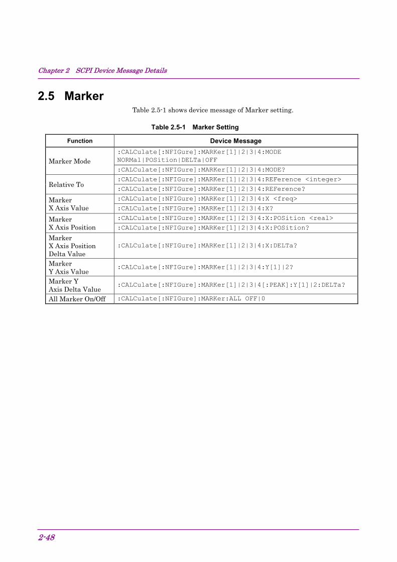
Chapter 2 SCPI Device Message Details
2-48
2.5 Marker Table 2.5-1 shows device message of Marker setting.
Table 2.5-1 Marker Setting
Function Device Message
Marker Mode :CALCulate[:NFIGure]:MARKer[1]|2|3|4:MODE NORMal|POSition|DELTa|OFF
:CALCulate[:NFIGure]:MARKer[1]|2|3|4:MODE?
Relative To :CALCulate[:NFIGure]:MARKer[1]|2|3|4:REFerence <integer>
:CALCulate[:NFIGure]:MARKer[1]|2|3|4:REFerence?
Marker X Axis Value
:CALCulate[:NFIGure]:MARKer[1]|2|3|4:X <freq>
:CALCulate[:NFIGure]:MARKer[1]|2|3|4:X?
Marker X Axis Position
:CALCulate[:NFIGure]:MARKer[1]|2|3|4:X:POSition <real>
:CALCulate[:NFIGure]:MARKer[1]|2|3|4:X:POSition?
Marker X Axis Position Delta Value
:CALCulate[:NFIGure]:MARKer[1]|2|3|4:X:DELTa?
Marker Y Axis Value
:CALCulate[:NFIGure]:MARKer[1]|2|3|4:Y[1]|2?
Marker Y Axis Delta Value
:CALCulate[:NFIGure]:MARKer[1]|2|3|4[:PEAK]:Y[1]|2:DELTa?
All Marker On/Off :CALCulate[:NFIGure]:MARKer:ALL OFF|0

2.5 Marker
2-49
2
SCPI Device M
essage Details
:CALCulate[:NFIGure]:MARKer[1]|2|3|4:MODE NORMal|DELTa|OFF Marker Mode
Function
Sets the Marker Mode.
Command :CALCulate[:NFIGure]:MARKer[n]:MODE[:STATe] <mode>
Parameter <n> Marker Number 1 Specifies Marker 1 2 Specifies Marker 2 3 Specifies Marker 3 4 Specifies Marker 4 Omitted Specifies Marker 1 <mode> Marker mode NORMal Normal marker DELTa Delta marker OFF Hidden marker Default Marker1 NORMal Others OFF
Example of Use To set Marker 2 marker mode to the delta marker. CALC:MARK2:MODE DELT

Chapter 2 SCPI Device Message Details
2-50
:CALCulate[:NFIGure]:MARKer[1]|2|3|4:MODE? Marker Mode Query
Function
Queries the Marker Mode.
Query :CALCulate[:NFIGure]:MARKer[n]:MODE[:STATe]?
Response <mode>
Parameter <n> Marker number 1 Specifies Marker 1 2 Specifies Marker 2 3 Specifies Marker 3 4 Specifies Marker 4 Omitted Specifies Marker 1 <mode> Marker mode NORM Normal marker DELT Delta marker OFF Hidden Marker
Example of Use To Reads the Marker 2 marker mode CALC:MARK2:MODE?
> DELT
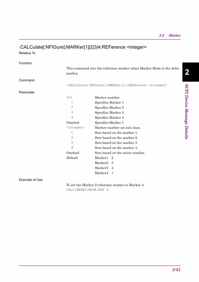
2.5 Marker
2-51
2
SCPI Device M
essage Details
:CALCulate[:NFIGure]:MARKer[1]|2|3|4:REFerence <integer> Relative To
Function
This command sets the reference marker when Marker Mode is the delta marker.
Command :CALCulate[:NFIGure]:MARKer[n]:REFerence <integer>
Parameter <n> Marker number 1 Specifies Marker 1 2 Specifies Marker 2 3 Specifies Marker 3 4 Specifies Marker 4 Omitted Specifies Marker 1 <integer> Marker number set into base. 1 Sets based on the marker 1. 2 Sets based on the marker 2. 3 Sets based on the marker 3. 4 Sets based on the marker 4. Omitted Sets based on the active marker. Default Marker1 2 Marker2 3 Marker3 4 Marker4 1
Example of Use To set the Marker 2 reference marker to Marker 4. CALC:MARK2:MODE:REF 4

Chapter 2 SCPI Device Message Details
2-52
:CALCulate[:NFIGure]:MARKer[1]|2|3|4:REFerence? Relative To
Function
This command queries the reference marker when Marker Mode is the delta marker.
Query :CALCulate[:NFIGure]:MARKer[n]:REFerence?
Response <integer>
Parameter <n> Marker Number 1 Specifies Marker 1 2 Specifies Marker 2 3 Specifies Marker 3 4 Specifies Marker 4 Omitted Specifies Marker 1 <integer> Base Marker number 1 Sets based on the marker 1. 2 Sets based on the marker 2. 3 Sets based on the marker 3. 4 Sets based on the marker 4.
Example of Use To read the reference marker of Marker 2 . CALC:MARK2:MODE:REF?
> 4

2.5 Marker
2-53
2
SCPI Device M
essage Details
:CALCulate[:NFIGure]:MARKer[1]|2|3|4:X <freq> Marker X Axis Value
Function
This command sets the marker position on the X axis with a frequency. Command
:CALCulate[:NFIGure]:MARKer[n]:X <freq>
Parameter <n> Marker number 1 Specifies Marker 1 2 Specifies Marker 2 3 Specifies Marker 3 4 Specifies Marker 4 Omitted Specifies Marker 1 <freq> X axis position When DUT mode is Amplifier or when DUT mode is not Amplifier and local frequency mode is fixed. Range Minimum 0 Hz Maximum [MS2690A] 6 GHz [MS2691A] 13.5 GHz [MS2692A] 26.5 GHz [MS2830A] 3.6 GHz (Option 040) 6 GHz (Option 041) 13.5 GHz (Option 043) 26.5 GHz (Option 044) 43 GHz (Option 045)
[MS2840A] 3.6 GHz (Option 040) 6 GHz (Option 041) 26.5 GHz (Option 044) 44.5 GHz (Option 046) [MS2850A] 32 GHz (Option 047) 44.5 GHz (Option 046)
When DUT mode is not Amplifier and local frequency mode is variable. Range Minimum 1 Hz Maximum 325 GHz (Upper limit frequency of external mixer
M03HW) Suffix code HZ, KHZ, KZ, MHZ, MZ, GHZ, GZ Hz is used when omitted. Default Current Start Frequency

Chapter 2 SCPI Device Message Details
2-54
Details When Frequency Mode is setting Fixed, this command is discounted. The range varies depending on the setting of DUT mode, Noise Source, LO Frequency, IF Frequency, or Sideband mode.
Example of Use To set the Marker 1 position on the X axis to 1 GHz. CALC:MARK1:X 1GHZ
:CALCulate[:NFIGure]:MARKer[1]|2|3|4:X? Marker X Axis Value Query
Function
This command queries the marker position on the X axis with a frequency.
Query :CALCulate[:NFIGure]:MARKer[n]:REFerence?
Response <freq>
Parameter <n> Marker number 1 Specifies Marker 1 2 Specifies Marker 2 3 Specifies Marker 3 4 Specifies Marker 4 Omitted Specifies Marker 1 <freq> Position of X Axis When DUT mode is Amplifier or when DUT mode is not Amplifier and local frequency mode is fixed. Range Minimum 0 Hz Maximum [MS2690A] 6 GHz [MS2691A] 13.5 GHz [MS2692A] 26.5 GHz [MS2830A] 3.6 GHz (Option 040) 6 GHz (Option 041) 13.5 GHz (Option 043) 26.5 GHz (Option 044) 43 GHz (Option 045)
[MS2840A] 3.6 GHz (Option 040) 6 GHz (Option 041) 26.5 GHz (Option 044) 44.5 GHz (Option 046) [MS2850A] 32 GHz (Option 047)

2.5 Marker
2-55
2
SCPI Device M
essage Details
44.5 GHz (Option 046) When DUT mode is not Amplifier and local frequency mode is variable. Range Minimum 1 Hz Maximum 325 GHz (Upper limit frequency of external
mixer M03HW) Suffix code None, Value is returned in Hz units
Details The range varies depending on the setting of DUT mode, Noise Source, LO Frequency, IF Frequency, or Sideband mode.
Example of Use To query the Marker 1 position on the X axis with a frequency CALC:MARK1:X?
> 1000000000
:CALCulate[:NFIGure]:MARKer[1]|2|3|4:X:POSition <Integer> Marker X Axis Position
Function
This command sets the marker position on the X axis with a point number.
Command :CALCulate[:NFIGure]:MARKer[n]:X <integer>
Parameter <n> Marker number 1 Specifies Marker 1 2 Specifies Marker 2 3 Specifies Marker 3 4 Specifies Marker 4 Omitted Specifies Marker 1 <real> Position of X Axis Range 0 to Current Point number – 1 Resolution 1 Suffix code None
Details When Frequency Mode is setting Fixed, this command is discounted
Example of Use To set the position on X axis of Marker 1 to 10th point. CALC:MARK1:X:POS 9

Chapter 2 SCPI Device Message Details
2-56
:CALCulate[:NFIGure]:MARKer[1]|2|3|4:X:POSition? Marker X Axis Position Query
Function
This command queries the marker position on the X axis by point.
Query :CALCulate[:NFIGure]:MARKer[n]:X?
Response <integer>
Parameter <n> Marker number 1 Specifies Marker 1 2 Specifies Marker 2 3 Specifies Marker 3 4 Specifies Marker 4 Omitted Specifies Marker 1 <integer> Position of X Axis Range 0 to Current Point number – 1 Resolution 1 Suffix code None
Example of Use To query the Marker 1 position on the X axis by point. CALC:MARK1:X:POS?
> 9

2.5 Marker
2-57
2
SCPI Device M
essage Details
:CALCulate[:NFIGure]:MARKer[1]|2|3|4:X:DELTa? Marker X Axis Position Delta Value
Function
This command queries the marker position on the X axis with a relative value of the frequency.
Query :CALCulate[:NFIGure]:MARKer[n]:X:DELTa?
Response <integer>
Parameter <n> Marker number 1 Specifies Marker 1 2 Specifies Marker 2 3 Specifies Marker 3 4 Specifies Marker 4 Omitted Specifies Marker 1 <integer> Relative value of the frequency on the X axis When DUT mode is Amplifier or when DUT mode is not Amplifier and local frequency mode is fixed. Range Minimum 0 Hz Maximum [MS2690A] 6 GHz [MS2691A] 13.5 GHz [MS2692A] 26.5 GHz [MS2830A] 3.6 GHz (Option 040) 6 GHz (Option 041) 13.5 GHz (Option 043) 26.5 GHz (Option 044) 43 GHz (Option 045)
[MS2840A] 3.6 GHz (Option 040) 6 GHz (Option 041) 26.5 GHz (Option 044) 44.5 GHz (Option 046) [MS2850A] 32 GHz (Option 047) 44.5 GHz (Option 046)
When DUT mode is not Amplifier and local frequency mode is variable. Range Minimum 1 Hz Maximum 325 GHz (Upper limit frequency of external
mixer M03HW) Suffix code None, Value is returned in Hz units

Chapter 2 SCPI Device Message Details
2-58
Details The range varies depending on the setting of DUT mode, Noise Source, LO Frequency, IF Frequency, or Sideband mode.
Example of Use To query the Marker 1 position on the X axis with a relative frequency CALC:MARK1:X:DELT?
> 9
:CALCulate[:NFIGure]:MARKer[1]|2|3|4:Y[1]|2? Marker Y Axis Value
Function
This command queries the Y axis value of the marker.
Query :CALCulate[:NFIGure]:MARKer[n1]:Y[n2]?
Response <value>
Parameter <n1> Marker number 1 Specifies Marker 1 2 Specifies Marker 2 3 Specifies Marker 3 4 Specifies Marker 4 Omitted Specifies Marker 1 <n2> Trace Number 1 Specifies Trace 1 2 Specifies Trace 2 Omitted Specifies Trace 1 <value> Value of Marker on the Y axis Range Depends on Result Type. Suffix code Non, the value unit depends on Result Type
Details When Frequency Mode is Fixed, value is returned null value.
Example of Use To query the Y axis value of Marker 1. CALC:MARK1:Y?
> 1.000

2.5 Marker
2-59
2
SCPI Device M
essage Details
:CALCulate[:NFIGure]:MARKer[1]|2|3|4[:PEAK]:Y[1]|2:DELTa? Marker Y Axis Delta Value
Function
This command queries the Y axis relative value of the marker.
Query :CALCulate[:NFIGure]:MARKer[1]|2|3|4[:PEAK]:Y[1]|2
:DELTa?
Response <value>
Parameter <value> Relation value of marker on the Y axis Range Depends on Result Type. Suffix code Non, the value unit depends on Result Type
Details When Frequency Mode is Fixed, value is returned null value.
Example of Use To reads the relation value of marker 1 on the Y axis. CALC:MARK1:Y:DELT?
> 1.0000
:CALCulate[:NFIGure]:MARKer:ALL OFF|0 All Marker Off
Function
This command switches all markers to Off
Command CALCulate[:NFIGure]:MARKer:ALL <switch>
Parameter <switch> All Marker Off OFF|0 Sets all markers to Off.
Example of Use To set all markers to Off CALC:MARK:ALL OFF
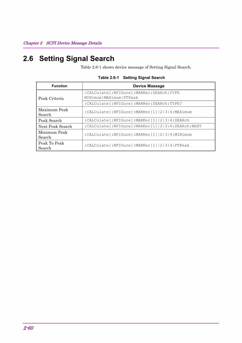
Chapter 2 SCPI Device Message Details
2-60
2.6 Setting Signal Search Table 2.6-1 shows device message of Setting Signal Search.
Table 2.6-1 Setting Signal Search
Function Device Massage
Peak Criteria :CALCulate[:NFIGure]:MARKer:SEARch:TYPE MINimum|MAXimum|PTPeak
:CALCulate[:NFIGure]:MARKer:SEARch:TYPE?
Maximum Peak Search
:CALCulate[:NFIGure]:MARKer[1]|2|3|4:MAXimum
Peak Search :CALCulate[:NFIGure]:MARKer[1]|2|3|4:SEARch
Next Peak Search :CALCulate[:NFIGure]:MARKer[1]|2|3|4:SEARch:NEXT
Minimum Peak Search
:CALCulate[:NFIGure]:MARKer[1]|2|3|4:MINimum
Peak To Peak Search
:CALCulate[:NFIGure]:MARKer[1]|2|3|4:PTPeak

2.6 Setting Signal Search
2-61
2
SCPI Device M
essage Details
:CALCulate[:NFIGure]:MARKer:SEARch:TYPE MINimum|MAXimum|PTPeak Peak Criteria
Function
This command sets the peak search type when Peak Search is executed.
Command :CALCulate[:NFIGure]:MARKer:SEARch:TYPE <mode>
Parameter <mode> Peak search type MINimum Sets the Minimum search MAXimum Sets the Maximum search PTPeak Sets the Peak To Peak search Default MAXimum
Details For Peak to Peak, Next Peak cannot be executed.
Example of Use To set the peak search type to Peak To Peak. CALC:MARK:SEAR:TYPE PTP
:CALCulate[:NFIGure]:MARKer:SEARch:TYPE? Peak Criteria Query
Function
This command queries the peak search type when Peak Search has been executed.
Query :CALCulate[:NFIGure]:MARKer:SEARch:TYPE?
Response <mode>
Parameter <mode> Peak Search type MIN Minimum search is set. MAX Maximum search is set. PTP Peak To Peak search is set.
Example of Use To query the peak search type. CALC:MARK:SEAR:TYPE?
> PTP

Chapter 2 SCPI Device Message Details
2-62
:CALCulate[:NFIGure]:MARKer[1]|2|3|4:MAXimum Maximum Peak Search
Function
This command executes Maximum search.
Command :CALCulate[:NFIGure]:MARKer[n]:MAXimum
Parameter <n> Marker number of to execute Maximum search. 1 Specifies Marker 1 2 Specifies Marker 2 3 Specifies Marker 3 4 Specifies Marker 4 Omitted Specifies Marker 1
Example of Use To execute Maximum search for Marker 1. CALC:MARK:MAX
:CALCulate[:NFIGure]:MARKer[1]|2|3|4:SEARch Peak Search
Function
This command executes the peak search.
Command :CALCulate[:NFIGure]:MARKer[n]:SEARch
Parameter <n> Specifies Marker number 1 Specifies Marker 1 2 Specifies Marker 2 3 Specifies Marker 3 4 Specifies Marker 4 Omitted Specifies Marker 1
Example of Use To execute the peak search. CALC:MARK:SEAR
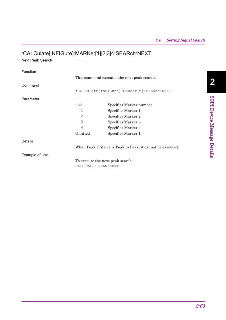
2.6 Setting Signal Search
2-63
2
SCPI Device M
essage Details
:CALCulate[:NFIGure]:MARKer[1]|2|3|4:SEARch:NEXT Next Peak Search
Function
This command executes the next peak search.
Command :CALCulate[:NFIGure]:MARKer[n]:SEARch:NEXT
Parameter <n> Specifies Marker number 1 Specifies Marker 1 2 Specifies Marker 2 3 Specifies Marker 3 4 Specifies Marker 4 Omitted Specifies Marker 1
Details When Peak Criteria is Peak to Peak, it cannot be executed.
Example of Use To execute the next peak search CALC:MARK:SEAR:NEXT

Chapter 2 SCPI Device Message Details
2-64
:CALCulate[:NFIGure]:MARKer[1]|2|3|4:MINimum Minimum Peak Search
Function
This command executes the Minimum search.
Command :CALCulate[:NFIGure]:MARKer[n]:MINimum
Parameter <n> Marker number of to execute Minimum search. 1 Specifies Marker 1 2 Specifies Marker 2 3 Specifies Marker 3 4 Specifies Marker 4 Omitted Specifies Marker 1
Example of Use To execute Minimum search for marker 1. CALC:MARK:MIN
:CALCulate[:NFIGure]:MARKer[1]|2|3|4:PTPeak Peak To Peak Search
Function
This command executes the Peak To Peak search.
Command :CALCulate[:NFIGure]:MARKer[n]:PTPeak
Parameter <n> Marker number of to execute Peak To Peak Search. 1 Specifies Marker 1 2 Specifies Marker 2 3 Specifies Marker 3 4 Specifies Marker 4 Omitted Specifies Marker 1
Example of Use To execute Peak To Peak search for marker 1. CALC:MARK:PTP

2.7 Trace
2-65
2
SCPI Device M
essage Details
2.7 Trace Table 2.7-1 shows device message of trace setting.
Table 2.7-1 Setting trace
Function Device message
Result Type :DISPlay[:NFIGure]:DATA:TRACe[1]|2[:RESult] NFIGure|NFACtor|GAIN|YFACtor|TEFFective|PHOT|PCOLd
:DISPlay[:NFIGure]:DATA:TRACe[1]|2[:RESult]?
Layout :DISPlay[:NFIGure]:FORMat GRAPh|TABLe
:DISPlay[:NFIGure]:FORMat?
Screen On/Off :DISPlay:SCReen <switch>
:DISPlay:SCReen?

Chapter 2 SCPI Device Message Details
2-66
:DISPlay[:NFIGure]:DATA:TRACe[1]|2[:RESult] NFIGure|NFACtor|GAIN|YFACtor|TEFFective|PHOT|PCOLd Result Type
Function
This command sets the trace Result Type.
Command :DISPlay[:NFIGure]:DATA:TRACe[n][:RESult] <result>
Parameter <n> Specifies Marker Number 1 Specifies Trace 1 2 Specifies Trace 2 <result> Result Type NFIGure Noise Figure NFACtor Noise Factor GAIN Gain YFACtor Y-Factor TEFFective T effective PHOT P hot PCOLd P cold Default Trace 1 NFIGure Trace 2 GAIN
Example of Use To set Trace 1 Result Type to Noise Factor. DISP:DATA:TRAC NFAC

2.7 Trace
2-67
2
SCPI Device M
essage Details
:CALCulate[:NFIGure]:MARKer:SEARch:TYPE? Result Type Query
Function
This command queries the trace Result Type.
Query :DISPlay[:NFIGure]:DATA:TRACe[n][:RESult]?
Response <result>
Parameter <n> Specifies Marker Number 1 Specifies Trace 1 2 Specifies Trace 2 <result> Result Type NFIG Noise Figure NFAC Noise Factor GAIN Gain YFAC Y-Factor TEFF T effective PHOT P hot PCOL P cold
Example of Use To query Trace 1 Result Type. DISP:DATA:TRAC?
> NFAC

Chapter 2 SCPI Device Message Details
2-68
:DISPlay[:NFIGure]:FORMat GRAPh|TABLe Layout
Function
This command sets the measured result display layout.
Command :DISPlay[:NFIGure]:FORMat <type>
Parameter <type> Layout Type. GRAPh Sets the layout to Graph display. TABLe Sets the layout to Table display. Default GRAPh
Example of Use To set the layout to Table display. DISP:FORM TABL
:DISPlay[:NFIGure]:FORMat? Layout Query
Function
This command queries the measured result display layout.
Query :DISPlay[:NFIGure]:FORMat?
Response <type>
Parameter <type> Layout type GRAP Layout is set to Graph display. TABL Layout is set to Table display.
Example of Use To read the layout. DISP:FORM?
> TABL

2.7 Trace
2-69
2
SCPI Device M
essage Details
:DISPlay:SCReen ON|OFF|0|1 Screen On/Off
Function
This command sets the display On/Off.
Command :DISPlay:SCReen <switch>
Parameter <switch> Display On/Off ON|1 Display sets to On. OFF|0 Display sets to Off. Default On
Example of Use To set the display off. DISP:SCR OFF
:DISPlay:SCReen? Screen Query
Function
This command queries the display On/Off.
Query :DISPlay:SCReen?
Response <switch>
Parameter <switch> Display On/Off 1 Display set to On. 0 Display set to Off.
Example of Use To queries the display On/Off. DISP:SCR?
> 0

Chapter 2 SCPI Device Message Details
2-70
2.8 Calibration Setting Table 2.8-1 shows device message of Calibration setting.
Table 2.8-1 Device message of Setting Calibration
Function Device message Calibrate Now [:SENSe][:NFIGure]:CALibration:INITiate
Clear User Cal Data
[:SENSe][:NFIGure]:CALibration:DELete
Apply Calibration [:SENSe][:NFIGure]:CALibration:STATe ON|OFF|1|0
[:SENSe][:NFIGure]:CALibration:STATe?
Max Attenuation [:SENSe][:NFIGure]:CALibration:USER:ATTenuation:MAXimum <integer>
[:SENSe][:NFIGure]:CALibration:USER:ATTenuation:MAXimum?
Min Attenuation [:SENSe][:NFIGure]:CALibration:USER:ATTenuation:MINimum <integer>
[:SENSe][:NFIGure]:CALibration:USER:ATTenuation:MINimum?

2.8 Calibration Setting
2-71
2
SCPI Device M
essage Details
[:SENSe][:NFIGure]:CALibration:INITiate Calibrate Now
Function
This command executes the NF Calibration
Command [:SENSe][:NFIGure]:CALibration:INITiate
Example of Use To Execute the NF Calibration. CAL:INIT
[:SENSe][:NFIGure]:CALibration:DELete Clear User Cal Data
Function
This command deletes all of NF Calibration data exists on the memory and, HDD or SSD.
Command [:SENSe][:NFIGure]:CALibration:DELete
Example of Use To delete NF Calibration data. CAL:DEL

Chapter 2 SCPI Device Message Details
2-72
[:SENSe][:NFIGure]:CALibration:STATe ON|OFF|1|0 Apply Calibration
Function
This command sets the On/off of adding NF Calibration data to measured results.
Command [:SENSe][:NFIGure]:CALibration:STATe <switch>
Parameter <switch> The On/Off of adding NF Calibration data to measured
results. ON|1 Adding sets to On. OFF|0 Adding sets to Off. Default OFF
Backwards Compatibility SCPI :DISPlay[:NFIGure]:DATA:CORRections[:STATe] <switch>
Details When NF Calibration data does not exist, even setting On does not perform addition.
Example of Use To enable adding NF Calibration data to measured results. CAL:STAT ON

2.8 Calibration Setting
2-73
2
SCPI Device M
essage Details
[:SENSe][:NFIGure]:CALibration:STATe? Apply Calibration Query
Function
This command queries the On/Off status of adding NF Calibration data to measured results.
Query [:SENSe][:NFIGure]:CALibration:STATe?
Response <switch>
Parameter <switch> The On/Off of adding NF Calibration data to measured
results. 1 Adding set to On. 0 Adding set to Off.
Backwards Compatibility SCPI :DISPlay[:NFIGure]:DATA:CORRections[:STATe]?
Example of Use To query the On/Off status of adding NF Calibration data to measured results. CAL:STAT?
> 1

Chapter 2 SCPI Device Message Details
2-74
[:SENSe][:NFIGure]:CALibration:USER:ATTenuation:MAXimum <integer> Max Attenuation
Function
This command sets the maximum attenuator value for NF Calibration.
Query [:SENSe][:NFIGure]:CALibration:USER:ATTenuation:MAXimum
<integer>
Parameter <integer> Maximum attenuator value for NF Calibration
Range 0 to 40 dB Resolution [MS269xA] 2 dB step [MS2830A] 2 dB step (Other than Option 045) 10 dB step (Option 045) [MS2840A] 2 dB step (except below) 10 dB step (Option 046 without Option 019/119) [MS2850A] 2 dB step Suffix code DB dB is used when omitted Default [MS269xA] 2 dB [MS2830A] 2 dB (Other than Option 045) 10 dB (Option 045) [MS2840A] 2 dB (except below) 10 dB (Option 046 without Option 019/119) [MS2850A] 2 dB
Backwards Compatibility SCPI :INPut[:NFIGure]:ATTenuation[:RF][:MAXimum] <integer>
:INPut[:NFIGure]:ATTenuation:MWAVe[:MAXimum] <integer>
Example of Use To set the maximum attenuator value for NF Calibration to 10 dB. CAL:USER:ATT:MAX 10DB

2.8 Calibration Setting
2-75
2
SCPI Device M
essage Details
[:SENSe][:NFIGure]:CALibration:USER:ATTenuation:MAXimum? Max Attenuation Query
Function
This command queries the maximum attenuator value for NF Calibration.
Query [:SENSe][:NFIGure]:CALibration:USER:ATTenuation:MAXimum?
Response <integer>
Parameter <integer> Maximum Value of Attenuator to execute NF
Calibration. Range 0 to 40 dB Resolution [MS269xA] 2 dB step [MS2830A] 2 dB step (Other than Option 045) 10 dB step (Option 045) [MS2840A] 2 dB step (except below) 10 dB step (Option 046 without Option 019/119) [MS2850A] 2 dB step Suffix code None, Value is returned in dB unit.
Backwards Compatibility SCPI :INPut[:NFIGure]:ATTenuation[:RF][:MAXimum]?
:INPut[:NFIGure]:ATTenuation:MWAVe[:MAXimum]?
Example of Use To query the maximum attenuator value for NF Calibration CAL:USER:ATT:MAX?
> 10

Chapter 2 SCPI Device Message Details
2-76
[:SENSe][:NFIGure]:CALibration:USER:ATTenuation:MINimum <integer> Min Attenuation
Function
This command sets the minimum attenuator value for NF Calibration.
Command [:SENSe][:NFIGure]:CALibration:USER:ATTenuation:MINimum
<integer>
Response <integer>
Parameter <integer> Minimum Value of Attenuator to execute NF
Calibration. Range 0 dB to 40 dB Resolution [MS269xA] 2 dB step [MS2830A] 2 dB step (Other than Option 045) 10 dB step (Option 045) [MS2840A] 2 dB step (except below) 10 dB step (Option 046 without Option 019/119) [MS2850A] 2 dB step Suffix code DB dB is used when omitted Default 0 dB
Backwards Compatibility SCPI :INPut[:NFIGure]:ATTenuation[:RF][:MINimum] <integer>
:INPut[:NFIGure]:ATTenuation:MWAVe[:MINimum] <integer>
Example of Use To set the minimum attenuator value for NF Calibration to 10 dB. CAL:USER:ATT:MIN 10DB

2.8 Calibration Setting
2-77
2
SCPI Device M
essage Details
[:SENSe][:NFIGure]:CALibration:USER:ATTenuation:MINimum? Min Attenuation Query
Function
This command queries the minimum attenuator value for NF Calibration.
Query [:SENSe][:NFIGure]:CALibration:USER:ATTenuation:MINimum?
Response <integer>
Parameter <integer> Minimum Value of Attenuator to execute NF
Calibration. Range 0 to 40 dB Resolution [MS269xA] 2 dB step [MS2830A] 2 dB step (Other than Option 045) 10 dB step (Option 045) [MS2840A] 2 dB step (except below) 10 dB step (Option 046 without Option 019/119) [MS2850A] 2 dB step Suffix code None, Value is returned in dB unit.
Backwards Compatibility SCPI :INPut[:NFIGure]:ATTenuation[:RF][:MINimum]?
:INPut[:NFIGure]:ATTenuation:MWAVe[:MINimum]?
Example of Use To query the minimum attenuator value for NF Calibration. CAL:USER:ATT:MIN?
> 10

Chapter 2 SCPI Device Message Details
2-78
2.9 Setting Correction Table 2.9-1 shows device Message of Setting Correction.
Table 2.9-1 Device message of setting Correction
Function Device message
Noise Source [:SENSe][:NFIGure]:CORRection:ENR:SOURce 346A|346B|346C|346D|346E|346K|USER
[:SENSe][:NFIGure]:CORRection:ENR:SOURce?
Noise Source Settling Time
[:SENSe][:NFIGure]:NSSTime <time>
[:SENSe][:NFIGure]:NSSTime?
ENR Mode [:SENSe][:NFIGure]:CORRection:ENR:MODE TABLe|SPOT
[:SENSe][:NFIGure]:CORRection:ENR:MODE?
Use Meas Table Data for Cal
[:SENSe][:NFIGure]:CORRection:ENR:COMMon[:STATe] ON|OFF|1|0
[:SENSe][:NFIGure]:CORRection:ENR:COMMon[:STATe]?
Meas Table Entry [:SENSe][:NFIGure]:CORRection:ENR[:MEASurement]:TABLe:DATA <freq_1>,<amp_1>[,<freq_2>,<amp_2>,…,<freq_n>,<amp_n>]
[:SENSe][:NFIGure]:CORRection:ENR[:MEASurement]:TABLe:DATA?
Meas Table Entry Count
[:SENSe][:NFIGure]:CORRection:ENR[:MEASurement]:TABLe:COUNt?
Clear Meas Table [:SENSe][:NFIGure]:CORRection:ENR[:MEASurement]:TABLe:DATA:DELete
Calibration Table Entry
[:SENSe][:NFIGure]:CORRection:ENR:CALibration:TABLe:DATA <freq_1>,<amp_1>[,<freq_2>,<amp_2>,…,<freq_n>,<amp_n>]
[:SENSe][:NFIGure]:CORRection:ENR:CALibration:TABLe:DATA?
Calibration Table Entry Count
[:SENSe][:NFIGure]:CORRection:ENR:CALibration:TABLe:COUNt?
Clear Calibration Table
[:SENSe][:NFIGure]:CORRection:ENR:CALibration:TABLe:DATA:DELete
Spot [:SENSe][:NFIGure]:CORRection:SPOT:MODE ENR|THOT
[:SENSe][:NFIGure]:CORRection:SPOT:MODE?
Spot ENR Value [:SENSe][:NFIGure]:CORRection:ENR:SPOT <value>
[:SENSe][:NFIGure]:CORRection:ENR:SPOT?
Spot T hot Value [:SENSe][:NFIGure]:CORRection:ENR:THOT <temperature>
[:SENSe][:NFIGure]:CORRection:ENR:THOT?

2.9 Setting Correction
2-79
2
SCPI Device M
essage Details
Table 2.9-1 Device message of setting Correction. (Cont’d)
Function Device Message
Loss Comp [:SENSe][:NFIGure]:CORRection:LOSS:BEFore|AFTer:MODE OFF|FIXed|TABLe
[:SENSe][:NFIGure]:CORRection:LOSS:BEFore|AFTer:MODE?
Loss Comp Fixed Value
[:SENSe][:NFIGure]:CORRection:LOSS:BEFore|AFTer:VALue <value>
[:SENSe][:NFIGure]:CORRection:LOSS:BEFore|AFTer:VALue?
Loss Comp Table [:SENSe][:NFIGure]:CORRection:LOSS:BEFore|AFTer:TABLe:DATA <freq_1>,<amp_1>[,<freq_2>,<amp_2>,…,<freq_n>,<amp_n>]
[:SENSe][:NFIGure]:CORRection:LOSS:BEFore|AFTer:TABLe:DATA?
Loss Comp Table Entry Count
[:SENSe][:NFIGure]:CORRection:LOSS:BEFore|AFTer:TABLe:COUNt?
Clear Loss Comp Table
[:SENSe][:NFIGure]:CORRection:LOSS:BEFore|AFTer:TABLe:DATA:DELete
T Cold Value [:SENSe][:NFIGure]:CORRection[:USER]:TCOLd:VALue <value>
[:SENSe][:NFIGure]:CORRection[:USER]:TCOLd:VALue?

Chapter 2 SCPI Device Message Details
2-80
[:SENSe][:NFIGure]:CORRection:ENR:SOURce 346A|346B|346C|346D|346E|346K|USER Noise Source
Function
This command selects the noise source.
Command [:SENSe][:NFIGure]:CORRection:ENR:SOURce <source>
Parameter <source> Noise source model 346A NC346A Option 1 346B NC346B Option 1 346C NC346C 346D NC346D Option 1 346E NC346E 346K NC346Ka USER Other Noise source Default USER
Details The settable frequency range depends on noise source models.
Example of Use To sets the noise source to NC346C. CORR:ENR:SOUR 346C

2.9 Setting Correction
2-81
2
SCPI Device M
essage Details
[:SENSe][:NFIGure]:CORRection:ENR:SOURce? Noise Source Query
Function
This command queries the selected noise source model.
Query [:SENSe][:NFIGure]:CORRection:ENR:SOURce?
Response <source>
Parameter <source> Noise source model 346A NC346A Option 1 346B NC346B Option 1 346C NC346C 346D NC346D Option 1 346E NC346E 346K NC346Ka USER Other Noise source
Example of Use To queries the noise source. CORR:ENR:SOUR?
> 346C

Chapter 2 SCPI Device Message Details
2-82
[:SENSe][:NFIGure]:NSSTime <time> Noise Source Settling Time
Function
This command sets Noise Source Settling Time.
Command [:SENSe][:NFIGure]:NSSTime < time >
Parameter <time> Noise Source Settling Time Range 0 to 5 s Resolution 1 ms Suffix code S, MS S is used when omitted Default 0 ms
Example of Use To sets the Noise Source Settling Time to 64 ms. NSST 64MS
[:SENSe][:NFIGure]:NSSTime? Noise Source Settling Time Query
Function
This command queries Noise Source Settling Time.
Query [:SENSe][:NFIGure]:NSSTime?
Response <time>
Parameter <time> Noise Source Settling Time Range 0 to 5 s Resolution 1 ms Suffix code None, Value is returned in s unit.
Example of Use To queries the Noise Source Settling Time. NSST?
>0.064
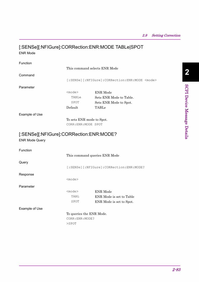
2.9 Setting Correction
2-83
2
SCPI Device M
essage Details
[:SENSe][:NFIGure]:CORRection:ENR:MODE TABLe|SPOT ENR Mode
Function
This command selects ENR Mode
Command [:SENSe][:NFIGure]:CORRection:ENR:MODE <mode>
Parameter <mode> ENR Mode TABLe Sets ENR Mode to Table. SPOT Sets ENR Mode to Spot. Default TABLe
Example of Use To sets ENR mode to Spot. CORR:ENR:MODE SPOT
[:SENSe][:NFIGure]:CORRection:ENR:MODE? ENR Mode Query
Function
This command queries ENR Mode
Query [:SENSe][:NFIGure]:CORRection:ENR:MODE?
Response <mode>
Parameter <mode> ENR Mode TABL ENR Mode is set to Table SPOT ENR Mode is set to Spot.
Example of Use To queries the ENR Mode. CORR:ENR:MODE?
>SPOT

Chapter 2 SCPI Device Message Details
2-84
[:SENSe][:NFIGure]:CORRection:ENR:COMMon[:STATe] ON|OFF|1|0 Use Meas Table Data for Cal
Function
This command sets ENR Table used for CAL function.
Command [:SENSe][:NFIGure]:CORRection:ENR:COMMon[:STATe] <switch>
Parameter <switch> Table used for calibration ON|1 Meas (ENR) Table is used. OFF|0 CAL Table is used. Default 1
Example of Use To set the table for calibration to Meas (ENR) Table. CORR:ENR:COMM ON
[:SENSe][:NFIGure]:CORRection:ENR:COMMon[:STATe]? Use Meas Table Data for Cal Query
Function
This command queries ENR Table used for CAL function.
Query [:SENSe][:NFIGure]:CORRection:ENR:MODE?
Response <switch>
Parameter <switch> Table used for calibration 1 Meas (ENR) Table is used. 0 CAL Table is used.
Example of Use To query the table used for calibration. CORR:ENR:COMM?
>1

2.9 Setting Correction
2-85
2
SCPI Device M
essage Details
[:SENSe][:NFIGure]:CORRection:ENR[:MEASurement]:TABLe:DATA <freq_1>,<amp_1>[,<freq_2>,<amp_2>,…,<freq_n>,<amp_n>] Meas Table Entry
Function
This command creates a new Measurement Table.
Command [:SENSe][:NFIGure]:CORRection:ENR[:MEASurement]:TABLe:DA
TA <freq_1>, <amp_1>[,<freq_2>,<amp_2>,…,<freq_n>,<amp_n>]
Parameter <freq_n> Frequency Range Minimum 0 Hz Maximum 100 GHz Resolution 1 Hz Suffix code HZ, KHZ, KZ, MHZ, MZ, GHZ, GZ Hz is used when omitted <amp_n> ENR Range –17.000 to 50.000 dB Resolution 0.001 dB Suffix code DB is used when omitted
Example of Use To creates a Measurement Table. CORR:ENR:TABL:DATA 1GHZ,10DB,2GHZ,15DB,3GHZ,20DB

Chapter 2 SCPI Device Message Details
2-86
[:SENSe][:NFIGure]:CORRection:ENR[:MEASurement]:TABLe:DATA? Meas Table Entry Query
Function
This command queries a new Meas Table.
Query [:SENSe][:NFIGure]:CORRection:ENR[:MEASurement]:TABLe:
DATA?
Response <freq_1>, <amp_1>[, <freq_2>, <amp_2>,…,<freq_n>,<amp_n>]
Parameter <freq_n> Frequency Range Minimum 0 Hz Maximum 100 GHz Resolution 1 Hz Suffix code None, Value is returned in Hz unit. <amp_n> ENR Range –17.000 to 50.000 dB Resolution 0.001 dB Suffix code None, Value is returned in s unit.
Example of Use To query the Meas Table. CORR:ENR:TABL:DATA?
> 1000000000,10,2000000000,15,3000000000,20

2.9 Setting Correction
2-87
2
SCPI Device M
essage Details
[:SENSe][:NFIGure]:CORRection:ENR[:MEASurement]:TABLe:COUNt? Meas Table Entry Count
Function
This command queries the Meas Table line count.
Query [:SENSe][:NFIGure]:CORRection:ENR[:MEASurement]:TABLe
:COUNt?
Response <integer>
Parameter <integer> Line count of Meas Table. Range 0 to 501 Suffix code None.
Example of Use To queries the line count of Meas Table. CORR:ENR:TABL:COUN?
> 10
[:SENSe][:NFIGure]:CORRection:ENR[:MEASurement]:TABLe:DATA:DELete Clear Meas Table
Function
This command clear the Meas Table.
Command [:SENSe][:NFIGure]:CORRection:ENR[:MEASurement]:TABLe:DA
TA:DELete
Example of Use To clear the Meas Table. CORR:ENR:TABL:DATA:DEL

Chapter 2 SCPI Device Message Details
2-88
[:SENSe][:NFIGure]:CORRection:ENR:CALibration:TABLe:DATA <freq_1>,<amp_1>[,<freq_2>,<amp_2>,…,<freq_n>,<amp_n>] Calibration Table Entry
Function
This command creates a new Cal Table.
Command [:SENSe][:NFIGure]:CORRection:ENR:CALibration:TABLe:DATA
<freq_1>,<amp_1>[,<freq_2>,<amp_2>,…,<freq_n>,<amp_n>]
Parameter <freq_n> Frequency Range Minimum 0 Hz Maximum 100 GHz Resolution 1 Hz Suffix code HZ, KHZ, KZ, MHZ, MZ, GHZ, GZ Hz is used when omitted <amp_n> ENR Range –17.000 to 50.000 dB Resolution 0.001 dB Suffix code DB, DB is used when omitted
Example of Use To creates a Cal Table. CORR:ENR:CAL:TABL:DATA 1GHZ,10DB,2GHZ,15DB,3GHZ,20DB

2.9 Setting Correction
2-89
2
SCPI Device M
essage Details
[:SENSe][:NFIGure]:CORRection:ENR:CALibration:TABLe:DATA? Calibration Table Entry Query
Function
This command queries a new Cal Table.
Query [:SENSe][:NFIGure]:CORRection:ENR:CALibration:TABLe:
DATA?
Response <freq_1>,<amp_1>[,<freq_2>,<amp_2>,…,<freq_n>,<amp_n>]
Parameter <freq_n> Frequency Range Minimum 0 Hz Maximum 100 GHz Resolution 1 Hz Suffix code None, Value is returned in Hz unit. <amp_n> ENR Range –17.000 to 50.000 dB Resolution 0.001 dB Suffix code None, Value is returned in dB unit.
Example of Use To query the Cal Table. CORR:ENR:CAL:TABL:DATA?
> 1000000000,10,2000000000,15,3000000000,20

Chapter 2 SCPI Device Message Details
2-90
[:SENSe][:NFIGure]:CORRection:ENR:CALibration:TABLe:COUNt? Calibration Table Entry Count
Function
This command queries the Cal Table line count.
Query [:SENSe][:NFIGure]:CORRection:ENR:CALibration:TABLe
:COUNt?
Response <integer>
Parameter <integer> Line count of Cal Table. Range 0 to 501 Suffix code None.
Example of Use To queries the line count of Cal Table. CORR:ENR:CAL:TABL:COUN?
> 10
[:SENSe][:NFIGure]:CORRection:ENR:CALibration:TABLe:DATA:DELete Clear Calibration Table
Function
This command clear the Cal Table.
Command [:SENSe][:NFIGure]:CORRection:ENR:CALibration:TABLe:DATA
:DELete
Example of Use To clear the Cal Table. CORR:ENR:CAL:TABL:DATA:DEL

2.9 Setting Correction
2-91
2
SCPI Device M
essage Details
[:SENSe][:NFIGure]:CORRection:SPOT:MODE ENR|THOT Spot
Function
This command selects ENR or T hot to be used when ENR Mode is Spot.
Command [:SENSe][:NFIGure]:CORRection:SPOT:MODE <mode>
Parameter <mode> ENR or T hot ENR Sets to use ENR. THOT Sets to use T-hot. Default ENR
Example of Use To set to select T hot. CORR:SPOT:MODE THOT
[:SENSe][:NFIGure]:CORRection:SPOT:MODE? Spot Query
Function
This command queries ENR or T hot to be used when ENR Mode is Spot
Query [:SENSe][:NFIGure]:CORRection:SPOT:MODE?
Response <mode>
Parameter <mode> ENR or T hot ENR Sets to use ENR. THOT Sets to use T-hot.
Example of Use To query which is selected ENR or T Hot, when ENR Mode is Spot. CORR:SPOT:MODE?
> THOT

Chapter 2 SCPI Device Message Details
2-92
[:SENSe][:NFIGure]:CORRection:ENR:SPOT <value> Spot ENR Value
Function
This Command sets the Spot ENR value.
Command [:SENSe][:NFIGure]:CORRection:ENR:SPOT <value>
Parameter <value> Spot ENR value. Range –17.000 to 50.000 dB Resolution 0.001 dB Suffix code DB dB is used when omitted Default 15.200 dB
Example of Use To set the Spot ENR value to 20.000 dB. CORR:ENR:SPOT 20DB
[:SENSe][:NFIGure]:CORRection:ENR:SPOT? Spot ENR Value Query
Function
This Command queries the Spot ENR value.
Query [:SENSe][:NFIGure]:CORRection:ENR:SPOT?
Response <value>
Parameter <value> Spot ENR value. Range –17.000 to 50.000 dB Resolution 0.001 dB Suffix code None, value is returned in dB unit.
Example of Use To read the Spot ENR value. CORR:ENR:SPOT?
>20

2.9 Setting Correction
2-93
2
SCPI Device M
essage Details
[:SENSe][:NFIGure]:CORRection:ENR:THOT <temperature> Spot T hot Value
Function
This Command sets the Spot T hot value.
Command [:SENSe][:NFIGure]:CORRection:ENR:THOT <temperature>
Parameter <value> Spot T hot value Range 0.00 to 29650000.00 K Resolution 0.01 Suffix code K, C, F Default 9892.80 K
Example of Use To set the Spot T hot value to 273.00 K. CORR:ENR:THOT 273K
[:SENSe][:NFIGure]:CORRection:ENR:THOT? Spot T hot Value Query
Function
This Command queries the Spot T Hot value.
Query [:SENSe][:NFIGure]:CORRection:ENR:THOT?
Response <value>
Parameter <value> Spot T hot value Range 0.00 to 29650000.00 K Resolution 0.01 K Suffix code None, value is returned in K unit.
Example of Use To read the Spot T hot value. CORR:ENR:THOT?
> 273.00

Chapter 2 SCPI Device Message Details
2-94
[:SENSe][:NFIGure]:CORRection:LOSS:BEFore|AFTer:MODE OFF|FIXed|TABLe Loss Comp
Function
This command sets the Loss Comp mode.
Command [:SENSe][:NFIGure]:CORRection:LOSS:BEFore|AFTer:MODE
<mode>
Parameter <select> Before DUT or After DUT BEFore Specifies Before DUT AFTer Specifies After DUT <mode> Mode setting OFF Sets the Loss Comp to Off FIXed Sets the Loss Comp to Fixed mode TABLe Sets the Loss Comp to Table mode Default OFF
Example of Use To set the mode of Loss Comp Before DUT to Table mode CORR:LOSS:BEF:MODE TABL

2.9 Setting Correction
2-95
2
SCPI Device M
essage Details
[:SENSe][:NFIGure]:CORRection:LOSS:BEFore|AFTer:MODE? Loss Comp Query
Function
This command queries the Loss Comp mode setting.
Query [:SENSe][:NFIGure]:CORRection:LOSS:BEFore|AFTer:MODE?
Response <mode>
Parameter <select> Before DUT or After DUT BEFore Specifies Before DUT AFTer Specifies After DUT <mode> Mode setting OFF Set the Loss Comp to off. FIX Set the Loss Comp to Fixed mode. TABL Set the Loss Comp to Table mode.
Example of Use To query the mode of Loss Comp Before DUT. CORR:LOSS:BEF:MODE?
> TABL

Chapter 2 SCPI Device Message Details
2-96
[:SENSe][:NFIGure]:CORRection:LOSS:BEFore|AFTer:VALue <value> Loss Comp Fixed Value
Function
This command Sets the Fixed mode value of Loss Comp.
Command [:SENSe][:NFIGure]:CORRection:LOSS:BEFore|AFTer:VALue
<value>
Parameter <select> Before DUT or After DUT BEFore Specifies Before DUT AFTer Specifies After DUT <value> Fixed mode value of Loss Comp Range –99.999999 to 99.999999 dB Resolution 0.000001 dB Suffix code DB, DB is used when omitted. Default 0 dB
Example of Use To set the Fixed mode value of Loss Comp Before DUT to 20 dB. CORR:LOSS:BEF:VAL 20DB

2.9 Setting Correction
2-97
2
SCPI Device M
essage Details
[:SENSe][:NFIGure]:CORRection:LOSS:BEFore|AFTer:VALue? Loss Comp Fixed Value Query
Function
This command queries the Fixed mode value of Loss Comp.
Query [:SENSe][:NFIGure]:CORRection:LOSS:BEFore|AFTer:VALue?
Response <value>
Parameter <select> Before DUT or After DUT BEFore Specifies Before DUT AFTer Specifies After DUT <value> Fixed mode value of Loss Comp. Range –99.999999 to 99.999999 dB Resolution 0.000001 dB Suffix code None, Value is returned in dB units
Example of Use To query the Fixed mode value of Loss Comp Before DUT. CORR:LOSS:BEF:VAL?
> 20.000000

Chapter 2 SCPI Device Message Details
2-98
[:SENSe][:NFIGure]:CORRection:LOSS:BEFore|AFTer:TABLe:DATA <freq_1>,<amp_1>[,<freq_2>, <amp_2>,…,<freq_n>,<amp_n>] Loss Comp Table
Function
This command creates the new Loss Comp Table.
Command [:SENSe][:NFIGure]:CORRection:LOSS:BEFore|AFTer:TABLe
:DATA <freq_1>,<amp_1>[,<freq_2>,<amp_2>,…,<freq_n>,
<amp_n>]
Parameter <table> Specified Table BEFore The Loss Comp Before DUT table is the target. AFTer The Loss Comp AFter DUT table is the target. <freq_n> Frequency Range Minimum 0 Hz Maximum 100 GHz Resolution 1 Hz Suffix code HZ, KHZ, KZ, MHZ, MZ, GHZ, GZ Hz is used when omitted <amp_n> Loss Value Range –99.999999 dB to 99.999999 dB Resolution 0.000001 dB Suffix code DB, DB is used when omitted
Example of Use To create the new Loss Comp Before DUT Table. CORR:LOSS:BEF:TABL:DATA 1GHZ,10DB,2GHZ,15DB,3GHZ,20DB

2.9 Setting Correction
2-99
2
SCPI Device M
essage Details
[:SENSe][:NFIGure]:CORRection:LOSS:BEFore|AFTer:TABLe:DATA? Loss Comp Table Query
Function
This command queries Loss Comp Table.
Query [:SENSe][:NFIGure]:CORRection:LOSS:BEFore|AFTer:TABLe
:DATA?
Response <freq_1>, <amp_1> [, <freq_2>, <amp_2>,…,<freq_n>,<amp_n>
Parameter <table> Specified Table BEFore The Loss Comp Before DUT table is the target AFTer The Loss Comp AFter DUT table is the target. <freq_n> Frequency Range Minimum 0 Hz Maximum 100 GHz Resolution 1 Hz Suffix code None, Value is returned in Hz unit. <amp_n> Loss Value Range –99.999999 dB to 99.999999 dB Resolution 0.000001 dB Suffix code None, Value is returned in dB unit.
Example of Use To query the Loss Comp Before DUT table. CORR:LOSS:BEF:TABL:DATA?
> 1000000000,10,2000000000,15,3000000000,20

Chapter 2 SCPI Device Message Details
2-100
[:SENSe][:NFIGure]:CORRection:LOSS:BEFore|AFTer:TABLe:COUNt? Loss Comp Table Entry Count
Function
This command queries the Loss Comp Table line count.
Query [:SENSe][:NFIGure]:CORRection:LOSS:BEFore|AFTer:TABLe
:COUNt?
Response <integer>
Parameter <table> Specified Table BEFore The Loss Comp Before DUT table is the target. AFTer The Loss Comp AFter DUT table is the target. <integer> Line count. of Loss Comp Table. Range 0 to 501 Suffix code None
Example of Use To query the line count of Loss Comp Before DUT table. CORR:LOSS:BEF:TABL:COUN?
> 10
[:SENSe][:NFIGure]:CORRection:LOSS:BEFore|AFTer:TABLe:DATA:DELete Clear Loss Comp Table
Function
This command clear the Loss Comp Table.
Command [:SENSe][:NFIGure]:CORRection:LOSS:BEFore|AFTer:TABLe
:DATA:DELete
Parameter <table> Specified Table BEFore The Loss Comp Before DUT table is the target. AFTer The Loss Comp AFter DUT table is the target.
Example of Use To Clear the Loss Comp Before DUT table. CORR:LOSS:BEF:TABL:DATA:DEL

2.9 Setting Correction
2-101
2
SCPI Device M
essage Details
[:SENSe][:NFIGure]:CORRection[:USER]:TCOLd:VALue <value> T Cold Value
Function
This command sets the T cold value.
Command [:SENSe][:NFIGure]:CORRection[:USER]:TCOLd:VALue <value>
Parameter <value> T cold value Range 0.00 to 29650000.00 K Resolution 0.01 K Suffix code K, C, F. K is used when omitted. Default 296.50 K
Example of Use To set the T cold to 290K. CORR:TCOL:VAL 290K
[:SENSe][:NFIGure]:CORRection[:USER]:TCOLd:VALue? T Cold Value Query
Function
This command queries the T cold value.
Query [:SENSe][:NFIGure]:CORRection[:USER]:TCOLd:VALue?
Response <value>
Parameter <value> T cold value Range 0.00 to 29650000.00 K Resolution 0.01 K Suffix code None, Value is returned in K unit.
Example of Use To query the T cold value. CORR:TCOL:VAL?
> 290

Chapter 2 SCPI Device Message Details
2-102
2.10 Setting DUT mode Table 2.10-1 shows device message of Setting DUT mode.
Table 2.10-1 DUT Mode Setting
Function Device message
DUT [:SENSe][:NFIGure]:MODE:DUT AMPLifier|UPConv|DOWNconv
[:SENSe][:NFIGure]:MODE:DUT?

2.10 Setting DUT mode
2-103
2
SCPI Device M
essage Details
[:SENSe][:NFIGure]:MODE:DUT AMPLifier|UPConv|DOWNconv DUT
Function
This command selects the DUT mode.
Command [:SENSe][:NFIGure]:MODE:DUT <mode>
Parameter <mode> DUT mode AMPLifier Amplifier mode UPConv Up converter mode DOWNconv Down converter mode Default AMPLifier
Backwards Compatibility SCPI [:SENSe]:CONFigure:MODE:DUT
Example of Use To set the DUT mode to Down converter. MODE:DUT DOWN
[:SENSe][:NFIGure]:MODE:DUT? DUT Query
Function
This command queries the DUT mode.
Query [:SENSe][:NFIGure]:MODE:DUT?
Response <mode>
Parameter <mode> DUT mode AMPL Amplifier mode UPC Up converter mode DOWN Down converter mode
Backwards Compatibility SCPI [:SENSe]:CONFigure:MODE:DUT?
Example of Use To set the DUT mode. MODE:DUT?
> DOWN

Chapter 2 SCPI Device Message Details
2-104
2.11 Execute measurement and query results Table 2.11-1 shows device messages to execute measurement and to query results.
Table 2.11-1 Device Messages to execute measurement and to query results
Function Device Messages
Continuous Measurement
:INITiate:CONTinuous OFF|ON|0|1
:INITiate:CONTinuous?
:INITiate:MODE:CONTinuous
Single Measurement
:INITiate:MODE:SINGle
Initiate :INITiate[:IMMediate]
Get Result :FETCh|MEASure|READ[:NFIGure]?
T Cold Scalar :FETCh|MEASure|READ[:NFIGure]:SCALar[:DATA]:TCOLd?
T Cold Array :FETCh|MEASure|READ[:NFIGure][:ARRay][:DATA]:TCOLd?
Corrected Results Scalar
:FETCh|MEASure|READ[:NFIGure]:SCALar[:DATA]:CORRected:NFIGure|NFACtor|GAIN|TEFFective|PHOT|PCOLd?
Corrected Result Array
:FETCh|MEASure|READ[:NFIGure][:ARRay][:DATA]:CORRected:NFIGure|NFACtor|GAIN|TEFFective|PHOT|PCOLd?
Uncorrected Results Scalar
:FETCh|MEASure|READ[:NFIGure:]SCALar[:DATA]:UNCorrected:NFIGure|NFACtor|YFACtor|TEFFective|PHOT|PCOLd?
Uncorrected Result Array
:FETCh|MEASure|READ[:NFIGure][:ARRay][:DATA]:UNCorrected:NFIGure|NFACtor|YFACtor|TEFFective|PHOT|PCOLd?
Maximum Noise Figure
:FETCh|MEASure|READ[:NFIGure]:METer:MAXimum?
Minimum Noise Figure
:FETCh|MEASure|READ[:NFIGure]:METer:MINimum?
Average Noise Figure
:FETCh|MEASure|READ[:NFIGure]:METer:AVERage?
Max To Min Noise Figure
:FETCh|MEASure|READ[:NFIGure]:METer:MTM?

2.11 Execute measurement and query results
2-105
2
SCPI Device M
essage Details
:INITiate:CONTinuous OFF|ON|0|1 Continuous Measurement
Function
This command switches the measurement execution mode Single/Continuous.
Command :INITiate:CONTinuous <switch>
Parameter <switch> Executing Measurement mode. 0|OFF Single measurement 1|ON ContinuousMeasurement (Default)
Details When On is set, Continuous status is held. When Off is set, Single status is held.
Example of Use To execute the Continuous measurement. INIT:CONT ON
:INITiate:CONTinuous? Continuous Measurement Query
Function
This command queries the measurement execution mode.
Query :INITiate:CONTinuous?
Response <switch>
Parameter <switch> Executing Measurement mode. 0 Single measurement 1 ContinuousMeasurement
Example of Use To query the Executing Measurement mode. INIT:CONT?
> 0

Chapter 2 SCPI Device Message Details
2-106
:INITiate:MODE:CONTinuous Continuous Measurement
Function
This command starts the Continuous measurement.
Command :INITiate:MODE:CONTinuous
Details Note that synchronization control during the Continuous mode is not supported.
Example of Use To execute the Continuous measurement. INIT:MODE:CONT
:INITiate:MODE:SINGle Single Measurement
Function
This command starts the Single measurement.
Command :INITiate:MODE:SINGle
Details When reading out measured values such as a marker value after executing this command, use the "*WAI" command to execute synchronization control.
Example of Use To execute the Single measurement, and to queries a marker value. INIT:MODE:SING
*WAI
CALC:MARK:Y?

2.11 Execute measurement and query results
2-107
2
SCPI Device M
essage Details
:INITiate[:IMMediate] Initiate
Function
This command starts the measurement in the current measurement execution mode.
Command :INITiate:[IMMediate]
Details When reading out measured values such as a marker value after executing this command, use the "*WAI" command to execute synchronization control. Note that synchronization control during the Continuous mode is not supported.
Example of Use To start the measurement in the current capture mode and query a marker value. INIT
*WAI
CALC:MARK:Y?
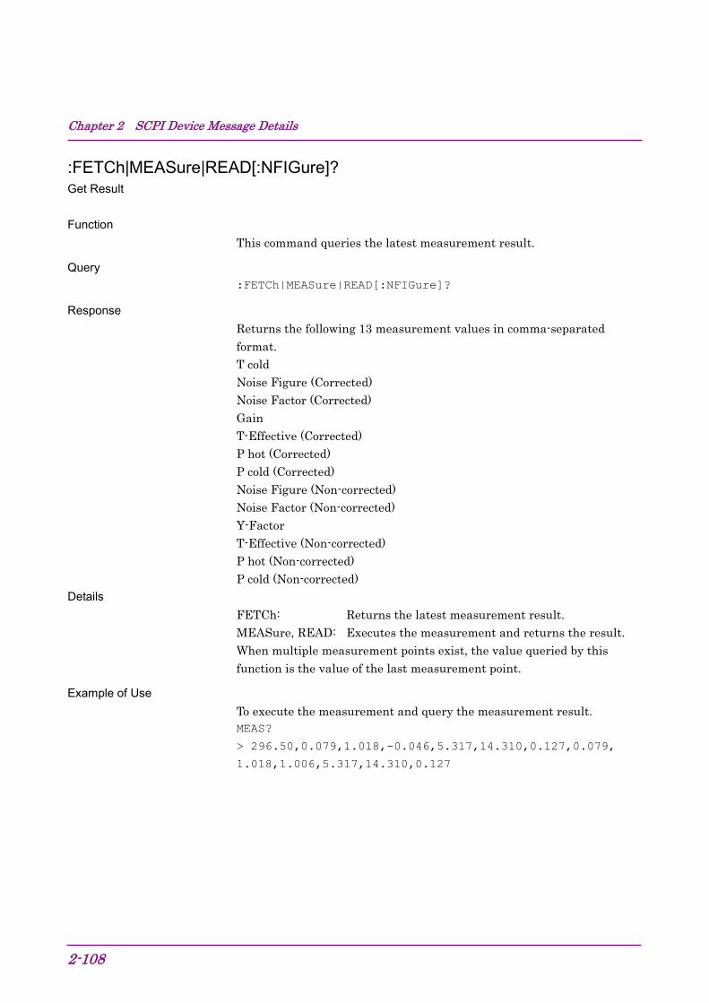
Chapter 2 SCPI Device Message Details
2-108
:FETCh|MEASure|READ[:NFIGure]? Get Result
Function
This command queries the latest measurement result.
Query :FETCh|MEASure|READ[:NFIGure]?
Response Returns the following 13 measurement values in comma-separated format. T cold Noise Figure (Corrected) Noise Factor (Corrected) Gain T-Effective (Corrected) P hot (Corrected) P cold (Corrected) Noise Figure (Non-corrected) Noise Factor (Non-corrected) Y-Factor T-Effective (Non-corrected) P hot (Non-corrected) P cold (Non-corrected)
Details FETCh: Returns the latest measurement result. MEASure, READ: Executes the measurement and returns the result. When multiple measurement points exist, the value queried by this function is the value of the last measurement point.
Example of Use To execute the measurement and query the measurement result. MEAS?
> 296.50,0.079,1.018,-0.046,5.317,14.310,0.127,0.079,
1.018,1.006,5.317,14.310,0.127

2.11 Execute measurement and query results
2-109
2
SCPI Device M
essage Details
:FETCh|MEASure|READ[:NFIGure]:SCALar[:DATA]:TCOLd? T Cold Scalar
Function
This command queries the T cold value on the latest measurement execution.
Query :FETCh|MEASure|READ[:NFIGure]:SCALar[:DATA]:TCOLd?
Response <tcold>
Parameter <tcold> T cold value on the latest measurement Range 0.00 to 29650000.00 K Resolution 0.01 K Suffix code None, in K unit.
Details FETCh: Returns the latest measurement result MEASure, READ: Executes the measurement and returns the result. When multiple measurement points exist, the value queried by this function is the value of the last measurement point.
Example of Use To query the T cold value on the latest measurement execution. FETC:SCAL:TCOL?
> 296.50

Chapter 2 SCPI Device Message Details
2-110
:FETCh|MEASure|READ[:NFIGure][:ARRay][:DATA]:TCOLd? T Cold Array
Function
This command queries the T cold values on the latest measurement execution for all measurement points.
Query :FETCh|MEASure|READ[:NFIGure][:ARRay][:DATA]:TCOLd?
Response <tcold>
Parameter <tcold> T cold value on the latest measurement execution Range 0.00 to 29650000.00 K Resolution 0.01 K Suffix code None, Value is returned in K units
Details FETCh: Returns the latest measurement result. MEASure, READ: Executes the measurement and returns the result.
Example of Use To query the T cold value on the latest measurement execution. FETC:TCOL?
> 296.50,296.50,296.50

2.11 Execute measurement and query results
2-111
2
SCPI Device M
essage Details
:FETCh|MEASure|READ[:NFIGure]:SCALar[:DATA]:CORRected:NFIGure|NFACtor|GAIN|TEFFective|PHOT|PCOLd? Corrected Results Scalar
Function
This command queries the latest corrected measurement result.
Query :FETCh|MEASure|READ[:NFIGure]:SCALar[:DATA]:CORRected:NF
IGure|NFACtor|GAIN|TEFFective|PHOT|PCOLd?
Response <value>
Parameter <result> Measurement result type NFIGure Noise Figure NFACtor Noise Factor GAIN Gain TEFFective T effective PHOT P hot PCOLd P cold <value> Various measurement results
Details FETCh: Returns the latest measurement result. MEASure, READ: Executes the measurement and returns the result. When multiple measurement points exist, the value queried by this function is the value of the last measurement point.
Example of Use To obtain the NF latest corrected measurement result. FETC:SCAL:CORR:NFIG?
> 0.079

Chapter 2 SCPI Device Message Details
2-112
:FETCh|MEASure|READ[:NFIGure][:ARRay][:DATA]:CORRected:NFIGure|NFACtor|GAIN|TEFFective|PHOT|PCOLd? Corrected Result Array
Function
This command queries the latest corrected measurement result for each measurement point.
Query :FETCh|MEASure|READ[:NFIGure][:DATA]:CORRected:NFIGure|N
FACtor|GAIN|TEFFective|PHOT|PCOLd?
Response <value>
Parameter <result> Measurement result type NFIGure Noise Figure NFACtor Noise Factor GAIN Gain TEFFective T effective PHOT P hot PCOLd P cold <value> Various measurement results
Details FETCh: Returns the latest measurement result. MEASure, READ: Executes the measurement and returns the result.
Example of Use To obtain the NF latest measurement result before correction. FETC:CORR:NFIG?
> 0.079,0.09,0.075

2.11 Execute measurement and query results
2-113
2
SCPI Device M
essage Details
:FETCh|MEASure|READ[:NFIGure:]SCALar[:DATA]:UNCorrected:NFIGure|NFACtor|YFACtor|TEFFective|PHOT|PCOLd? Uncorrected Results Scalar
Function
This command queries the latest measurement result before correction.
Query :FETCh|MEASure|READ[:NFIGure]:SCALar[:DATA]:UNCorrected:
NFIGure|NFACtor|GAIN|TEFFective|PHOT|PCOLd?
Response <value>
Parameter <result> Measurement result type NFIGure Noise Figure NFACtor Noise Factor GAIN Gain TEFFective T effective PHOT P hot PCOLd P cold <value> Various measurement results
Details FETCh: Returns the latest measurement result MEASure, READ: Executes the measurement and returns the result. When multiple measurement points exist, the value queried by this function is the value of the last measurement point.
Example of Use To obtain the NF latest measurement result before correction. FETC:SCAL:UNC:NFIG?
> 0.079

Chapter 2 SCPI Device Message Details
2-114
:FETCh|MEASure|READ[:NFIGure][:ARRay][:DATA]:UNCorrected:NFIGure|NFACtor|YFACtor|TEFFective|PHOT|PCOLd? Uncorrected Result Array
Function
This command queries the latest measurement result before correction for each measurement point.
Query :FETCh|MEASure|READ[:NFIGure][:DATA]:UNCorrected:NFIGure
|NFACtor|GAIN|TEFFective|PHOT|PCOLd?
Response <value>
Parameter <result> Measurement result NFIGure Noise Figure NFACtor Noise Factor GAIN Gain TEFFective T effective PHOT P hot PCOLd P cold <value> Various measurement results
Details FETCh: Returns the latest measurement result. MEASure, READ: Executes the measurement and returns the result.
Example of Use To query the latest measurement result before correction. FETC:UNC:NFIG?
> 0.079,0.09,0.075

2.11 Execute measurement and query results
2-115
2
SCPI Device M
essage Details
:FETCh|MEASure|READ[:NFIGure]:METer:MAXimum? Maximum Noise Figure
Function
This command queries the Noise Figure maximum value when the meter reads.
Query :FETCh|MEASure|READ[:NFIGure]:METer:MAXimum?
Response <max> Noise Figure maximum value
Details With this command, FETCh, MEASure, and READ have the same execution result. When Frequency Mode is not Fixed, –999.00 is returned.
Example of Use To query the Noise Figure maximum value. FETC:MET:MAX?
> 0.5
:FETCh|MEASure|READ[:NFIGure]:METer:MINimum? Minimum Noise Figure
Function
This command queries the Noise Figure minimum value when the meter reads.
Query :FETCh|MEASure|READ[:NFIGure]:METer:MINimum?
Response <min> Noise Figure minimum value
Details With this command, FETCh, MEASure, and READ have the same execution result. When Frequency Mode is not Fixed, –999.00 is returned.
Example of Use To query the Noise Figure minimum value. FETC:MET:MIN?
> 0.001

Chapter 2 SCPI Device Message Details
2-116
:FETCh|MEASure|READ[:NFIGure]:METer:AVERage? Average Noise Figure
Function
This command queries the Noise Figure average value when the meter reads.
Query :FETCh|MEASure|READ[:NFIGure]:METer:AVERage?
Response <avg> Noise Figure average value
Details With this command, FETCh, MEASure, and READ have the same execution result. When Frequency Mode is not Fixed, –999.00 is returned.
Example of Use To query the Noise Figure average value FETC:MET:AVER?
> 0.03
:FETCh|MEASure|READ[:NFIGure]:METer:MTM? Max To Min Noise Figure
Function
This command queries the difference between Noise Figure maximum and minimum values when the meter reads.
Query :FETCh|MEASure|READ[:NFIGure]:METer:MTM?
Response <mtm> Difference between Noise Figure maximum and
minimum values
Details With this command, FETCh, MEASure, and READ have the same execution result. When Frequency Mode is not Fixed, –999.00 is returned.
Example of Use Queries the difference between Noise Figure maximum and minimum values. FETC:MET:MTM?
> 0.499

2.12 Save / Load Files
2-117
2
SCPI Device M
essage Details
2.12 Save / Load Files Table 2.12-1 shows device message of save / load files.
Table 2.12-1 Save / Load Files
Function Device Messages Save Meas Table :MMEMory:STORe:ENR[:MEASurement] [<file_name>[,<device>]]
Load Meas Table :MMEMory:LOAD:ENR[:MEASurement] <file_name>[,<device>]
Save Cal Table :MMEMory:STORe:ENR:CALibration [<file_name>[,<device>]]
Load Cal Table :MMEMory:LOAD:ENR:CALibration <file_name>[,<device>]
Save Frequency List
:MMEMory:STORe:FREQuency [<file_name>[,<device>]]
Load Frequency List
:MMEMory:LOAD:FREQuency <file_name>[,<device>]
Save Loss Comp Table
:MMEMory:STORe:LOSS BEFore|AFTer[,<file_name>[,<device>]]
Load Loss Comp Table
:MMEMory:LOAD:LOSS BEFore|AFTer,<file_name>[,<device>]
Export Meas Results
:MMEMory:STORe:RESults [<file_name>[,<device>]]

Chapter 2 SCPI Device Message Details
2-118
:MMEMory:STORe:ENR[:MEASurement] [<file_name>[,<device>]] Save Meas Table
Function
This command saves Meas Table.
Command :MMEMory:STORe:ENR[:MEASurement] [<file_name>[,<device>]]
Parameter <file_name> File name <device> Drive name
(A,B,D,E,…, D drive is used when omitted.)
Details The file is saved in CSV format.
Example of Use To save Meas Table as a file name, "Test_Measure" MMEM:STOR:ENR “Test_Measure”
:MMEMory:LOAD:ENR[:MEASurement] <file_name>[,<device>] Load Meas Table
Function
This command loads Meas Table.
Command :MMEMory:LOAD:ENR[:MEASurement] <file_name>[,<device>]
Parameter <file_name> File name <device> Drive name
(A,B,D,E,…, D drive is used when omitted.)
Example of Use To load the file "Test_Measure" to set it in Meas Table. MMEM:LOAD:ENR “Test_Measure”

2.12 Save / Load Files
2-119
2
SCPI Device M
essage Details
:MMEMory:STORe:ENR:CALibration [<file_name>[,<device>]] Save Cal Table
Function
This command saves Cal Table.
Command :MMEMory:STORe:ENR:CALibration [<file_name>[,<device>]]
Parameter <file_name> File name <device> Drive name
(A,B,D,E,…, D drive is used when omitted.)
Details The file is saved in CSV format.
Example of Use To save Cal Table as a file name, "Test_Calibration" MMEM:STOR:ENR:CAL “Test_Calibration”
:MMEMory:LOAD:ENR:CALibration <file_name>[,<device>] Load Meas Table
Function
This command loads Cal Table.
Command :MMEMory:LOAD:ENR:CALibration <file_name>[,<device>]
Parameter <file_name> File name <device> Drive name
(A,B,D,E,…, D drive is used when omitted.)
Example of Use To load the file "Test_Calibration" to set it in Cal Table. MMEM:LOAD:ENR:CAL “Test_Calibration”

Chapter 2 SCPI Device Message Details
2-120
:MMEMory:STORe:FREQuency [<file_name>[,<device>]] Save Frequency List
Function
This command saves Frequency List in a file.
Command :MMEMory:STORe:FREQuency [<file_name>[,<device>]]
Parameter <file_name> File name <device> Drive name
(A,B,D,E,…, D drive is used when omitted.)
Details The file is saved in CSV format.
Example of Use To save Frequency List as a file name, "Test_FreqList" MMEM:STOR:FREQ “Test_FreqList”
:MMEMory:LOAD:FREQuency <file_name>[,<device>] Load Frequency List
Function
This command loads Frequency List from a file.
Command :MMEMory:LOAD:FREQuency <file_name>[,<device>]
Parameter <file_name> File name <device> Drive name
(A,B,D,E,…, D drive is used when omitted.)
Example of Use To load the file "Test_FreqList" to set it in Frequency List. MMEM:LOAD:FREQ “Test_FreqList”

2.12 Save / Load Files
2-121
2
SCPI Device M
essage Details
:MMEMory:STORe:LOSS BEFore|AFTer[,<file_name>[,<device>]] Save Loss Comp Table
Function
This command saves Loss Comp Table in a file.
Command :MMEMory:STORe:LOSS BEFore|AFTer[,<file_name>[,<device>]]
Parameter <file_name> File name <device> Drive name
(A,B,D,E,…, D drive is used when omitted.)
Details The file is saved in CSV format.
Example of Use To save the Loss Comp Before DUT table as a file name, "Test_LCBDUT". MMEM:STOR:LOSS BEF,“Test_LCBDUT”
:MMEMory:LOAD:LOSS BEFore|AFTer,<file_name>[,<device>] Load Loss Comp Table
Function
This command loads Loss Comp Table from a file.
Command :MMEMory:LOAD:LOSS BEFore|AFTer, <file_name>[,<device>]
Parameter <file_name> File name <device> Drive name
(A,B,D,E,…, D drive is used when omitted.)
Example of Use To load the file "Test_LCBDUT" to set it in the Loss Comp Before DUT table. MMEM:LOAD:LOSS BEF,“Test_LCBDUT”

Chapter 2 SCPI Device Message Details
2-122
:MMEMory:STORe:RESults [<file_name>[,<device>]] Export Meas Results
Function
This command saves a measurement result in a file.
Command :MMEMory:STORe:RESults [<file_name>[,<device>]]
Parameter <file_name> File name <device> Drive name
(A,B,D,E,…, D drive is used when omitted.)
Details The file is saved in CSV format.
Example of Use To save a measurement result as a file name, "Test_Result" MMEM:STOR:RES “Test_Result”

2.13 Setting Convert
2-123
2
SCPI Device M
essage Details
2.13 Setting Convert Table 2.13-1 lists device messages related to convert settings.
Table 2.13-1 Convert Setting
Function Device Messages
DUT LO Mode [:SENSe][:NFIGure]:MODE:DUT:LOSCillator FIXed|VARiable
[:SENSe][:NFIGure]:MODE:DUT:LOSCillator?
Downconverter Fixed IF Frequency
[:SENSe][:NFIGure]:MODE:DOWNconv:IF:FREQuency <freq>
[:SENSe][:NFIGure]:MODE:DOWNconv:IF:FREQuency?
Downconverter Fixed LO Frequency
[:SENSe][:NFIGure]:MODE:DOWNconv:LOSCillator:FREQuency <freq>
[:SENSe][:NFIGure]:MODE:DOWNconv:LOSCillator:FREQuency?
Downconverter LO Offset
[:SENSe][:NFIGure]:MODE:DOWNconv:LOSCillator:OFFSet DSB|LSB|USB
[:SENSe][:NFIGure]:MODE:DOWNconv:LOSCillator:OFFSet?
Upconverter Fixed IF Frequency
[:SENSe][:NFIGure]:MODE:UPConv:IF:FREQuency <freq>
[:SENSe][:NFIGure]:MODE:UPConv:IF:FREQuency?
Upconverter Fixed LO Frequency
[:SENSe][:NFIGure]:MODE:UPConv:LOSCillator:FREQuency <freq>
[:SENSe][:NFIGure]:MODE:UPConv:LOSCillator:FREQuency?
Upconverter LO Offset
[:SENSe][:NFIGure]:MODE:UPConv:LOSCillator:OFFSet DSB|LSB|USB
[:SENSe][:NFIGure]:MODE:UPConv:LOSCillator:OFFSet?

Chapter 2 SCPI Device Message Details
2-124
[:SENSe][:NFIGure]:MODE:DUT:LOSCillator FIXed|VARiable DUT LO Mode
Function
This command selects local frequency mode for upconverting/downconverting.
Command [:SENSe][:NFIGure]:MODE:DUT:LOSCillator <mode>
Parameter <mode> DUT Local mode FIXed Fixed mode VARiable Variable mode Default FIXed
Backwards Compatibility SCPI [:SENSe]:CONFigure:MODE:DUT:LOSCillator
Example of Use To set local frequency fixed mode. MODE:DUT:LOSC FIX
[:SENSe][:NFIGure]:MODE:DUT:LOSCillator? DUT LO Mode Query
Function
This command queries local frequency mode for upconverting/downconverting.
Query [:SENSe][:NFIGure]:MODE:DUT:LOSCillator?
Response <mode>
Parameter <mode> Converter Local mode FIX Fixed mode VAR Variable mode
Backwards Compatibility SCPI [:SENSe]:CONFigure:MODE:DUT:LOSCillator?
Example of Use To query local frequency fixed mode. MODE:DUT:LOSC?
> FIX

2.13 Setting Convert
2-125
2
SCPI Device M
essage Details
[:SENSe][:NFIGure]:MODE:DOWNconv:IF:FREQuency <freq> Downconverter Fixed IF Frequency
Function
This command sets IF Frequency when local frequency mode of Downconverter mode is varied.
Command [:SENSe][:NFIGure]:MODE:DOWNconv:IF:FREQuency <freq>
Parameter <freq> IF Frequency Range 1 Hz to the upper limit frequency of the main unit Resolution 1 Hz Suffix code HZ, KHZ, KZ, MHZ, MZ, GHZ, GZ Hz is used when omitted. Default 30 MHz
Backwards Compatibility SCPI [:SENSe]:CONFigure:MODE:DOWNconv:IF:FREQuency
Example of Use To set IF Frequency of Downconverter mode to 1 GHz. MODE:DOWN:IF:FREQ 1GHZ

Chapter 2 SCPI Device Message Details
2-126
[:SENSe][:NFIGure]:MODE:DOWNconv:IF:FREQuency? Downconverter Fixed IF Frequency Query
Function
This command queries IF Frequency when local frequency mode of Downconverter mode is varied.
Query [:SENSe][:NFIGure]:MODE:DOWNconv:IF:FREQuency?
Response <freq>
Parameter <freq> IF Frequency Range 1 Hz to the upper limit frequency of the main unit Resolution 1 Hz
Backwards Compatibility SCPI [:SENSe]:CONFigure:MODE:DOWNconv:LOSCillator:FREQuency?
Example of Use To query IF Frequency of Downconverter mode. MODE:DOWN:IF:FREQ?
> 1000000000

2.13 Setting Convert
2-127
2
SCPI Device M
essage Details
[:SENSe][:NFIGure]:MODE:DOWNconv:LOSCillator:FREQuency <freq> Downconverter Fixed LO Frequency
Function
This command sets LO Frequency when local frequency mode of Downconverter mode is fixed.
Command [:SENSe][:NFIGure]:MODE:DOWNconv:LOSCillator:FREQuency
<freq>
Parameter <freq> LO Frequency Range 2 Hz to 325 GHz (when sideband mode is DSB) 3 Hz to 325 GHz (when sideband mode is LSB) 2 Hz to 325 GHz (when sideband mode is USB) Resolution 1 Hz Suffix code HZ, KHZ, KZ, MHZ, MZ, GHZ, GZ Hz is used when omitted. Default 10 GHz
Backwards Compatibility SCPI [:SENSe]:CONFigure:MODE:DOWNconv:LOSCillator:FREQuency
Example of Use To set LO Frequency of Downconverter mode to 1 GHz. MODE:DOWN:LOSC:FREQ 1GHZ

Chapter 2 SCPI Device Message Details
2-128
[:SENSe][:NFIGure]:MODE:DOWNconv:LOSCillator:FREQuency? Downconverter Fixed LO Frequency Query
Function
This command queries LO Frequency when local frequency mode of Downconverter mode is fixed.
Query [:SENSe][:NFIGure]:MODE:DOWNconv:LOSCillator:FREQuency
Response <freq>
Parameter <freq> LO Frequency Range 2 Hz to 325 GHz (when sideband mode is DSB) 3 Hz to 325 GHz (when sideband mode is LSB) 2 Hz to 325 GHz (when sideband mode is USB) Resolution 1 Hz
Backwards Compatibility SCPI [:SENSe]:CONFigure:MODE:DOWNconv:LOSCillator:FREQuency?
Example of Use To query LO Frequency of Downconverter mode. MODE:DOWN:LOSC:FREQ?
> 1000000000

2.13 Setting Convert
2-129
2
SCPI Device M
essage Details
[:SENSe][:NFIGure]:MODE:DOWNconv:LOSCillator:OFFSet DSB|LSB|USB Downconverter LO Offset
Function
This command sets LO Offset of Downconverter mode.
Command [:SENSe][:NFIGure]:MODE:DOWNconv:LOSCillator:OFFSet
<mode>
Parameter <mode> Frequency offset mode DSB Double sideband (without offset) LSB Lower sideband (Signal frequency < LO Frequency) USB Upper sideband (Signal frequency > LO Frequency) Default LSB
Backwards Compatibility SCPI [:SENSe]:CONFigure:MODE:DOWNconv:LOSCillator:OFFSet
Example of Use To set LO Offset of Downconverter mode to Double sideband. MODE:DOWN:LOSC:OFFS DSB
[:SENSe][:NFIGure]:MODE:DOWNconv:LOSCillator:OFFSet? Downconverter LO Offset Query
Function
This command queries LO Offset of Downconverter mode.
Query [:SENSe][:NFIGure]:MODE:DOWNconv:LOSCillator:OFFSet?
Response <mode>
Parameter <mode> Frequency offset mode DSB Double sideband (without offset) LSB Lower sideband (Signal frequency < LO Frequency) USB Upper sideband (Signal frequency > LO Frequency)
Backwards Compatibility SCPI [:SENSe]:CONFigure:MODE:DOWNconv:LOSCillator:OFFSet?
Example of Use To query LO Offset of Downconverter mode. MODE:DOWN:LOSC:OFFS?
> DSB

Chapter 2 SCPI Device Message Details
2-130
[:SENSe][:NFIGure]:MODE:UPConv:IF:FREQuency <freq> Upconverter Fixed IF Frequency
Function
This command sets IF Frequency when local frequency mode of Upconverter mode is varied.
Command [:SENSe][:NFIGure]:MODE:UPConv:IF:FREQuency <freq>
Parameter <freq> IF Frequency Range 1 Hz to the upper limit frequency of the main unit Resolution 1 Hz Suffix code HZ, KHZ, KZ, MHZ, MZ, GHZ, GZ Hz is used when omitted. Default 30 MHz
Backwards Compatibility SCPI [:SENSe]:CONFigure:MODE:UPConv:IF:FREQuency
Example of Use To set IF Frequency of Upconverter mode to 1 GHz. MODE:UPC:IF:FREQ 1GHZ

2.13 Setting Convert
2-131
2
SCPI Device M
essage Details
[:SENSe][:NFIGure]:MODE:UPConv:IF:FREQuency? Upconverter Fixed IF Frequency Query
Function
This command queries IF Frequency when local frequency mode of Upconverter mode is varied.
Query [:SENSe][:NFIGure]:MODE:UPConv:IF:FREQuency?
Response <freq>
Parameter <freq> IF Frequency Range 1 Hz to the upper limit frequency of the main unit Resolution 1 Hz
Backwards Compatibility SCPI [:SENSe]:CONFigure:MODE:UPConv:IF:FREQuency?
Example of Use To query IF Frequency of Upconverter mode. MODE:UPC:IF:FREQ?
> 1000000000

Chapter 2 SCPI Device Message Details
2-132
[:SENSe][:NFIGure]:MODE:UPConv:LOSCillator:FREQuency <freq> Upconverter Fixed LO Frequency
Function
This command sets LO Frequency when local frequency mode of Upconverter mode is fixed.
Command [:SENSe][:NFIGure]:MODE:UPConv:LOSCillator:FREQuency
<freq>
Parameter <freq> LO Frequency Range 2 Hz to 325 GHz Resolution 1 Hz Suffix code HZ, KHZ, KZ, MHZ, MZ, GHZ, GZ Hz is used when omitted. Default 10 GHz
Backwards Compatibility SCPI [:SENSe]:CONFigure:MODE:UPConv:LOSCillator:FREQuency
Example of Use To set LO Frequency of Upconverter mode to 1 GHz. MODE:UPC:LOSC:FREQ 1GHZ

2.13 Setting Convert
2-133
2
SCPI Device M
essage Details
[:SENSe][:NFIGure]:MODE:UPConv:LOSCillator:FREQuency? Upconverter Fixed LO Frequency Query
Function
This command queries LO Frequency when local frequency mode of Upconverter mode is fixed.
Query [:SENSe][:NFIGure]:MODE:UPConv:LOSCillator:FREQuency
Response <freq>
Parameter <freq> LO Frequency Range 2 Hz to 325 GHz Resolution 1 Hz
Backwards Compatibility SCPI [:SENSe]:CONFigure:MODE:UPConv:LOSCillator:FREQuency?
Example of Use To query LO Frequency of Upconverter mode. MODE:UPC:LOSC:FREQ?
> 1000000000

Chapter 2 SCPI Device Message Details
2-134
[:SENSe][:NFIGure]:MODE:UPConv:LOSCillator:OFFSet LSB|USB Upconverter LO Offset
Function
This command sets LO Offset of Upconverter mode.
Command [:SENSe][:NFIGure]:MODE:UPConv:LOSCillator:OFFSet <mode>
Parameter <mode> Frequency offset mode LSB Lower sideband (Signal frequency < LO Frequency) USB Upper sideband (Signal frequency > LO Frequency) Default LSB
Backwards Compatibility SCPI [:SENSe]:CONFigure:MODE:UPConv:LOSCillator:OFFSet
Example of Use To set LO Offset of Upconverter mode to Upper sideband. MODE:UPC:LOSC:OFFS USB
[:SENSe][:NFIGure]:MODE:UPConv:LOSCillator:OFFSet? Upconverter LO Offset Query
Function
This command queries LO Offset of Upconverter mode.
Query [:SENSe][:NFIGure]:MODE:UPConv:LOSCillator:OFFSet?
Response <mode>
Parameter <mode> Frequency offset mode LSB Lower sideband (Signal frequency < LO Frequency) USB Upper sideband (Signal frequency > LO Frequency)
Backwards Compatibility SCPI [:SENSe]:CONFigure:MODE:UPConv:LOSCillator:OFFSet?
Example of Use To query LO Offset of Upconverter mode. MODE:UPC:LOSC:OFFS?
> USB

2.14 Setting External LO
2-135
2
SCPI Device M
essage Details
2.14 Setting External LO Table 2.14-1 lists the device messages related to External LO settings.
Table 2.14-1 External LO Setting
Function Device Messages
External LO Control
SYSTem:CONFigure:LOSCillator:CONTrol[:STATe] OFF|ON|0|1
SYSTem:CONFigure:LOSCillator:CONTrol[:STATe]?
External LO Select SYSTem:CONFigure:LOSCillator:SELect INTernal|EXTernal
SYSTem:CONFigure:LOSCillator:SELect?
GPIB Address Select for External LO
:SYSTem:COMMunicate:GPIB[1][:SELF]:ADDRess <integer>
:SYSTem:COMMunicate:GPIB[1][:SELF]:ADDRess?
External LO Type SYSTem:CONFigure:LOSCillator:TYPE SCPI|CUSTom
SYSTem:CONFigure:LOSCillator:TYPE?
External LO Auxiliary Command
SYSTem:CONFigure:LOSCillator:COMMand:AUXiliary <command>
SYSTem:CONFigure:LOSCillator:COMMand:AUXiliary?
External LO Frequency Prefix
SYSTem:CONFigure:LOSCillator:COMMand:FREQuency:PREFix <prefix>
SYSTem:CONFigure:LOSCillator:COMMand:FREQuency:PREFix?
External LO Frequency Suffix
SYSTem:CONFigure:LOSCillator:COMMand:FREQuency:SUFFix <suffix>
SYSTem:CONFigure:LOSCillator:COMMand:FREQuency:SUFFix?
External LO Power Prefix
SYSTem:CONFigure:LOSCillator:COMMand:POWer:PREFix <prefix>
SYSTem:CONFigure:LOSCillator:COMMand:POWer:PREFix?
External LO Power Suffix
SYSTem:CONFigure:LOSCillator:COMMand:POWer:SUFFix <suffix>
SYSTem:CONFigure:LOSCillator:COMMand:POWer:SUFFix?
External LO Power Level
SYSTem:CONFigure:LOSCillator:PARameter:POWer[:LEVel] <ampl>
SYSTem:CONFigure:LOSCillator:PARameter:POWer[:LEVel]?
External LO Settling Time
SYSTem:CONFigure:LOSCillator:PARameter:SETTling[:TIME] <time>
SYSTem:CONFigure:LOSCillator:PARameter:SETTling[:TIMe]?
External LO Maximum Frequency
SYSTem:CONFigure:LOSCillator:PARameter:MAXimum[:FREQuency] <freq>
SYSTem:CONFigure:LOSCillator:PARameter:MAXimum[:FREQuency]?
External LO Minimum Frequency
SYSTem:CONFigure:LOSCillator:PARameter:MINimum[:FREQuency] <freq>
SYSTem:CONFigure:LOSCillator:PARameter:MINimum[:FREQuency]?

Chapter 2 SCPI Device Message Details
2-136
:SYSTem:CONFigure:LOSCillator:CONTrol[:STATe] OFF|ON|0|1 External LO Control
Function
This command controls External LO.
Command :SYSTem:CONFigure:LOSCillator:CONTrol[:STATe] <switch>
Parameter <switch> External LO Control OFF|0 Off (Default) ON|1 On
Example of Use To control External LO. SYST:CONF:LOSC:CONT ON
:SYSTem:CONFigure:LOSCillator:CONTrol[:STATe]? External LO Control Query
Function
This command queries External LO control.
Query :SYSTem:CONFigure:LOSCillator:CONTrol[:STATe]?
Response <switch>
Parameter <switch> External LO Control 0 Off (Default) 1 On
Example of Use To query External LO control. SYST:CONF:LOSC:CONT?
> 1

2.14 Setting External LO
2-137
2
SCPI Device M
essage Details
:SYSTem:CONFigure:LOSCillator:SELect INTernal|EXTernal External LO Select
Function
This command selects External LO.
Command :SYSTem:CONFigure:LOSCillator:SELect <select>
Parameter <select> External LO Select INTernal Internal SG option (Default) EXTernal External Signal Generator
Example of Use To set External LO Select to Internal SG option. SYST:CONF:LOSC:SEL INT
:SYSTem:CONFigure:LOSCillator:SELect? External LO Select Query
Function
This command queries External LO Select.
Query :SYSTem:CONFigure:LOSCillator:SELect?
Response <select>
Parameter <select> External LO Select INT Internal SG option (Default) EXT External Signal Generator
Example of Use To query External LO Select. SYST:CONF:LOSC:SEL?
> INT

Chapter 2 SCPI Device Message Details
2-138
:SYSTem:COMMunicate:GPIB[1][:SELF]:ADDRess <integer> GPIB Address Select for External LO
Function
This command sets the GPIB address for External LO.
Command :SYSTem:COMMunicate:GPIB[1][:SELF]:ADDRess <integer>
Parameter <integer> GPIB Address Range 0 to 30 Resolution 1 Suffix code None Default 18
Example of Use To set the GPIB address for External LO to 0. SYST:COMM:GPIB:ADDR 0
:SYSTem:COMMunicate:GPIB[1][:SELF]:ADDRess? GPIB Address Select for External LO Query
Function
This command queries the GPIB address for External LO.
Query :SYSTem:COMMunicate:GPIB[1][:SELF]:ADDRess?
Response <integer>
Parameter <integer> GPIB Address Range 0 to 30 Resolution 1
Example of Use To query the GPIB address for External LO. SYST:COMM:GPIB:ADDR?
> 0

2.14 Setting External LO
2-139
2
SCPI Device M
essage Details
:SYSTem:CONFigure:LOSCillator:TYPE SCPI|CUSTom External LO Type
Function
This command sets command type for External LO control.
Command :SYSTem:CONFigure:LOSCillator:TYPE <type>
Parameter <type> Command type for External LO control SCPI SCPI command (Default) CUSTom Arbitrary setting command
Example of Use To control External LO by SCPI command. SYST:CONF:LOSC:TYPE SCPI
:SYSTem:CONFigure:LOSCillator:TYPE? External LO Type Query
Function
This command queries type for External LO control.
Query :SYSTem:CONFigure:LOSCillator:TYPE?
Response <type>
Parameter <type> External LO control SCPI SCPI command (Default) CUST Arbitrary setting command
Example of Use To query command type for External LO control SYST:CONF:LOSC:TYPE?
> CUST

Chapter 2 SCPI Device Message Details
2-140
:SYSTem:CONFigure:LOSCillator:COMMand:AUXiliary <command> External LO Auxiliary Command
Function
This command sets auxiliary command for External LO.
Command :SYSTem:CONFigure:LOSCillator:COMMand:AUXiliary <command>
Parameter <command> Command character string Character string within 79 characters enclosed by
double quotes (“ ”) or single quotes (‘ ’) (excluding extension)
The following characters cannot be used: ¥ / ? “ ” ‘ ’ < > | Default OUTP:STAT ON
Example of Use To set auxiliary command ‘OUTP:STAT ON’ to External LO. SYST:CONF:LOSC:COMM:AUX 'OUTP:STAT ON'
:SYSTem:CONFigure:LOSCillator:COMMand:AUXiliary? External LO Auxiliary Command Query
Function
This command queries the auxiliary command set for External LO.
Query :SYSTem:CONFigure:LOSCillator:COMMand:AUXiliary?
Response <command>
Parameter <command> Command character string Character string within 79 characters enclosed by
double quotes (“ ”) or single quotes (‘ ’) (excluding extension)
Example of Use To query the auxiliary command set for External LO. SYST:CONF:LOSC:COMM:AUX?
> OUTP:STAT ON

2.14 Setting External LO
2-141
2
SCPI Device M
essage Details
:SYSTem:CONFigure:LOSCillator:COMMand:FREQuency:PREFix <prefix> External LO Frequency Prefix
Function
This command sets in External LO the frequency command that is added as a prefix to a frequency value set for External LO.
Command :SYSTem:CONFigure:LOSCillator:COMMand:FREQuency:PREFix
<prefix>
Parameter <prefix> Command character string Character string within 79 characters enclosed by
double quotes (“ ”) or single quotes (‘ ’) (excluding extension)
The following characters cannot be used: ¥ / ? “ ” ‘ ’ < > | Default FREQ
Example of Use To set the frequency command ‘FREQ’ in External LO. SYST:CONF:LOSC:COMM:FREQ:PREF 'FREQ'
:SYSTem:CONFigure:LOSCillator:COMMand:FREQuency:PREFix? External LO Frequency Prefix Query
Function
This command queries the frequency command set in External LO.
Query :SYSTem:CONFigure:LOSCillator:COMMand:FREQuency:PREFix?
Response <prefix>
Parameter <prefix> Command character string Character string within 79 characters enclosed by
double quotes (“ ”) or single quotes (‘ ’) (excluding extension)
Example of Use To query the frequency command set in External LO. SYST:CONF:LOSC:COMM:FREQ:PREF?
> FREQ

Chapter 2 SCPI Device Message Details
2-142
:SYSTem:CONFigure:LOSCillator:COMMand:FREQuency:SUFFix <suffix> External LO Frequency Suffix
Function
This command sets in External LO the suffix code that is added as a suffix to a frequency value set for External LO.
Command :SYSTem:CONFigure:LOSCillator:COMMand:FREQuency:SUFFix
<suffix>
Parameter <suffix> Command character string Character string within 79 characters enclosed by
double quotes (“ ”) or single quotes (‘ ’) (excluding extension)
The following characters cannot be used: ¥ / ? “ ” ‘ ’ < > | Default HZ
Example of Use To set the frequency suffix code ‘HZ’ in External LO. SYST:CONF:LOSC:COMM:FREQ:SUFF 'HZ'
:SYSTem:CONFigure:LOSCillator:COMMand:FREQuency:SUFFix? External LO Frequency Suffix Query
Function
This command queries the frequency suffix code set in External LO.
Query :SYSTem:CONFigure:LOSCillator:COMMand:FREQuency:SUFFix?
Response <suffix>
Parameter <suffix> Command character string Character string within 79 characters enclosed by
double quotes (“ ”) or single quotes (‘ ’) (excluding extension)
Example of Use To query the frequency suffix code set in External LO. SYST:CONF:LOSC:COMM:FREQ:SUFF
> HZ

2.14 Setting External LO
2-143
2
SCPI Device M
essage Details
:SYSTem:CONFigure:LOSCillator:COMMand:POWer:PREFix <prefix> External LO Power Prefix
Function
This command sets in External LO the output level command that is added as a prefix to a power value set for External LO.
Command :SYSTem:CONFigure:LOSCillator:COMMand:POWer:PREFix
<prefix>
Parameter <prefix> Command character string DSB Character string within 79 characters enclosed by
double quotes (“ ”) or single quotes (‘ ’) (excluding extension)
The following characters cannot be used: ¥ / ? “ ” ‘ ’ < > | Default POW
Example of Use To set the output level command ‘POW’ in External LO. SYST:CONF:LOSC:COMM:POW:PREF 'POW'
:SYSTem:CONFigure:LOSCillator:COMMand:POWer:PREFix? External LO Power Prefix Query
Function
This command queries the output level command set in External LO.
Query :SYSTem:CONFigure:LOSCillator:COMMand:POWer:PREFix?
Response <prefix>
Parameter <prefix> Command character string Character string within 79 characters enclosed by
double quotes (“ ”) or single quotes (‘ ’) (excluding extension)
Example of Use To query the output level command set in External LO. SYST:CONF:LOSC:COMM:POW:PREF?
> POW

Chapter 2 SCPI Device Message Details
2-144
:SYSTem:CONFigure:LOSCillator:COMMand:POWer:SUFFix <suffix> External LO Power Suffix
Function
This command sets in External LO the suffix code that is added as a suffix to output level set for External LO.
Command :SYSTem:CONFigure:LOSCillator:COMMand:POWer:SUFFix
<suffix>
Parameter <suffix> Command character string Character string within 79 characters enclosed by
double quotes (“ ”) or single quotes (‘ ’) (excluding extension)
The following characters cannot be used: ¥ / ? “ ” ‘ ’ < > | Default DBM
Example of Use To set the output-level suffix code ‘DBM’ in External LO. SYST:CONF:LOSC:COMM:POW:SUFF 'DBM'
:SYSTem:CONFigure:LOSCillator:COMMand:POWer:SUFFix? External LO Power Suffix Query
Function
This command queries the suffix code of output level set in External LO.
Query :SYSTem:CONFigure:LOSCillator:COMMand:POWer:SUFFix?
Response <suffix>
Parameter <suffix> Command character string Character string within 79 characters enclosed by
double quotes (“ ”) or single quotes (‘ ’) (excluding extension)
Example of Use To query the suffix code of output level set in External LO. SYST:CONF:LOSC:COMM:POW:SUFF?
> DBM

2.14 Setting External LO
2-145
2
SCPI Device M
essage Details
:SYSTem:CONFigure:LOSCillator:PARameter:POWer[:LEVel] <ampl> External LO Power Level
Function
This command sets the output level of External LO.
Command :SYSTem:CONFigure:LOSCillator:PARameter:POWer[:LEVel]
<ampl>
Parameter <ampl> Output Level Range –100.0 to 100.0 dBm Resolution 0.1 dB Default 0.0 dB Suffix code DBM DBM is used when omitted
Example of Use To set the output level of External LO to 1.0 dBm. SYST:CONF:LOSC:PAR:POW 1.0
:SYSTem:CONFigure:LOSCillator:PARameter:POWer[:LEVel]? External LO Power Level Query
Function
This command queries the output level set in External LO.
Query :SYSTem:CONFigure:LOSCillator:PARameter:POWer[:LEVel]?
Response <ampl>
Parameter <ampl> Output Level Range –100.0 to 100.0 dBm Resolution 0.1 dB Suffix code None, value is returned in dBm units.
Example of Use To query the output level set in External LO. SYST:CONF:LOSC:PAR:POW?
> 1.0

Chapter 2 SCPI Device Message Details
2-146
:SYSTem:CONFigure:LOSCillator:PARameter:SETTling[:TIME] <time> External LO Settling Time
Function
This command sets settling time (stabilizing time) of External LO.
Command :SYSTem:CONFigure:LOSCillator:PARameter:SETTling[:TIME]
<time>
Parameter <time> Settling Time (stabilizing time) Range 0 to 5 s Resolution 1 ms Default 0 ms Suffix code MS, S S is used when omitted
Example of Use To set settling time of External LO to 0.2 s. SYST:CONF:LOSC:PAR:SETT 0.2
:SYSTem:CONFigure:LOSCillator:PARameter:SETTling[:TIMe]? External LO Settling Time Query
Function
This command queries the settling time (stabilizing time) set in External LO.
Query :SYSTem:CONFigure:LOSCillator:PARameter:SETTling[:TIMe]?
Response <time>
Parameter <type> Settling Time (stabilizing time) Range 0 to 5 s Resolution 1 ms Suffix code None. Value is returned in s units.
Example of Use To query the settling time set in External LO. SYST:CONF:LOSC:PAR:SETT?
> 0.2

2.14 Setting External LO
2-147
2
SCPI Device M
essage Details
:SYSTem:CONFigure:LOSCillator:PARameter:MAXimum[:FREQuency] <freq> External LO Maximum Frequency
Function
This command sets Maximum Frequency of External LO.
Command :SYSTem:CONFigure:LOSCillator:PARameter:MAXimum[:FREQuen
cy] <freq>
Parameter <freq> Maximum Frequency Range
Minimum [MS2830A], [MS2840A] 100 kHz [MS2690A/MS2691A/MS2692A] 125 MHz [External LO] 0 Hz Maximum [MS2830A-020], [MS2840A-020] 3.6 GHz [MS2690A/91A/92A-020] 6 GHz [MS2830A-021], [MS2840A-021] 6 GHz [External LO] 325 GHz Resolution 1 Hz Suffix code HZ, KHZ, KZ, MHZ, MZ, GHZ, GZ Hz is used when omitted.
Example of Use To set Maximum Frequency of External LO to 1 GHz. SYST:CONF:LOSC:PAR:MAX 1GHZ

Chapter 2 SCPI Device Message Details
2-148
:SYSTem:CONFigure:LOSCillator:PARameter:MAXimum[:FREQuency]? External LO Maximum Frequency Query
Function
This command queries Maximum Frequency set in External LO.
Query :SYSTem:CONFigure:LOSCillator:PARameter:MAXimum[:FREQuen
cy]?
Response <freq>
Parameter <freq> Maximum Frequency Range
Minimum [MS2830A], [MS2840A] 100 kHz [MS2690A/MS2691A/MS2692A] 125 MHz [External LO] 0 Hz Maximum [MS2830A-020], [MS2840A-020] 3.6 GHz [MS2690A/91A/92A-020] 6 GHz [MS2830A-021], [MS2840A-021] 6 GHz [External LO] 325 GHz Suffix code None. Value is returned in Hz units.
Example of Use To query Maximum Frequency set in External LO. SYST:CONF:LOSC:PAR:MAX?
> 1000000000

2.14 Setting External LO
2-149
2
SCPI Device M
essage Details
:SYSTem:CONFigure:LOSCillator:PARameter:MINimum[:FREQuency] <freq> External LO Minimum Frequency
Function
This command sets Minimum Frequency of External LO.
Command :SYSTem:CONFigure:LOSCillator:PARameter:MINimum[:FREQuen
cy] <freq>
Parameter <freq> Minimum Frequency Range
Minimum [MS2830A], [MS2840A] 100 kHz [MS2690A/MS2691A/MS2692A] 125 MHz [External LO] 0 Hz Maximum [MS2830A-020], [MS2840A-020] 3.6 GHz [MS2690A/91A/92A-020] 6 GHz [MS2830A-021], [MS2840A-021] 6 GHz [External LO] 325 GHz Resolution 1 Hz Suffix code HZ, KHZ, KZ, MHZ, MZ, GHZ, GZ Hz is used when omitted.
Example of Use To set Minimum Frequency of External LO to 100 MHz. SYST:CONF:LOSC:PAR:MIN 100MHZ

Chapter 2 SCPI Device Message Details
2-150.
:SYSTem:CONFigure:LOSCillator:PARameter:MINimum[:FREQuency]? External LO Minimum Frequency Query
Function
This command queries Minimum Frequency set in External LO.
Query :SYSTem:CONFigure:LOSCillator:PARameter:MINimum[:FREQuen
cy]?
Response <freq>
Parameter <freq> Minimum Frequency Range
Minimum [MS2830A], [MS2840A] 100 kHz [MS2690A/MS2691A/MS2692A] 125 MHz [External LO] 0 Hz Maximum [MS2830A-020], [MS2840A-020] 3.6 GHz [MS2690A91A/92A]-020 6 GHz [MS2830A-021], [MS2840A-021] 6 GHz [External LO] 325 GHz Suffix code None. Value is returned in Hz units.
Example of Use To query Minimum Frequency set in External LO. SYST:CONF:LOSC:PAR:MIN?
> 100000000

Chapter 3 SCPI Status Register
3-1
3
SCPI Status Register
This chapter describes the SCPI commands and the Status register for querying application statuses.
3.1 Querying Measurement Status ............................................................................................................... 3-2 :STATus:ERRor? ..................................................................................................................................... 3-2
3.2 Questionable Status Register ................................................................................................................. 3-3 :STATus:QUEStionable[:EVENt]? ............................................................................................................ 3-6 :STATus:QUEStionable:CONDition? ....................................................................................................... 3-6 :STATus:QUEStionable:ENABle <integer> .............................................................................................. 3-7 :STATus:QUEStionable:ENABle? ............................................................................................................ 3-7 :STATus:QUEStionable:NTRansition <integer> ...................................................................................... 3-8 :STATus:QUEStionable:NTRansition? ..................................................................................................... 3-8 :STATus:QUEStionable:PTRansition <integer> ...................................................................................... 3-9 :STATus:QUEStionable:PTRansition? ..................................................................................................... 3-9 :STATus:QUEStionable:MEASure[:EVENt]? ......................................................................................... 3-10 :STATus:QUEStionable:MEASure:CONDition? ..................................................................................... 3-10 :STATus:QUEStionable:MEASure:ENABle <integer> ............................................................................3-11 :STATus:QUEStionable:MEASure:ENABle? ..........................................................................................3-11 :STATus:QUEStionable:MEASure:NTRansition <integer> .................................................................... 3-12 :STATus:QUEStionable:MEASure:NTRansition? .................................................................................. 3-12 :STATus:QUEStionable:MEASure:PTRansition <integer> .................................................................... 3-13 :STATus:QUEStionable:MEASure:PTRansition? .................................................................................. 3-13
3.3 Operation Status:Register ..................................................................................................................... 3-14 :STATus:OPERation[:EVENt]? .............................................................................................................. 3-15 :STATus:OPERation:CONDition? .......................................................................................................... 3-15 :STATus:OPERation:ENABle <integer> ................................................................................................ 3-16 :STATus:OPERation:ENABle? .............................................................................................................. 3-16 :STATus:OPERation:NTRansition <integer> ......................................................................................... 3-17 :STATus:OPERation:NTRansition? ....................................................................................................... 3-17 :STATus:OPERation:PTRansition <integer> ......................................................................................... 3-18 :STATus:OPERation:PTRansition? ....................................................................................................... 3-18
3.4 Utility...................................................................................................................................................... 3-19 :DISPlay:ANNotation:WUP:ERASe ....................................................................................................... 3-19 :DISPlay:ANNotation:TITLe[:STATe] OFF|ON|0|1 ................................................................................. 3-20 :DISPlay:ANNotation:TITLe[:STATe]? ................................................................................................... 3-20 :DISPlay:ANNotation:TITLe:DATA <string> ........................................................................................... 3-21 :DISPlay:ANNotation:TITLe:DATA? ....................................................................................................... 3-21

Chapter 3 SCPI Status Register
3-2
3.1 Querying Measurement Status :STATus:ERRor? Measurement Status Query Function
Queries the measurement status.
Query :STATus:ERRor?
Response <status>
Parameter <status> Measurement status
Value = bit0 + bit1 + bit2 + bit3 + bit4 + bit5 + bit6 + bit7 + bit8 + bit9 + bit10 + bit11 + bit12 + bit13 + bit14 + bit15
bit0 : 20 = 1 Not measured bit1 : 21 = 2 Exceeded the level. bit2 : 22 = 4 (Unused) bit3 : 23 = 8 (Unused) bit4 : 24 = 16 (Unused) bit5 : 25 = 32 (Unused) bit6 : 26 = 64 (Unused) bit7 : 27 = 128 (Unused) bit8 : 28 = 256 (Unused) bit9 : 29 = 512 (Unused) bit10 : 210 = 1024 (Unused) bit11 : 211 = 2048 (Unused) bit12 : 212 = 4096 (Unused) bit13 : 213 = 8192 (Unused) bit14 : 214 = 16384 (Unused) bit15 : 215 = 32768 (Unused)
Range 0 to 65535
Details 0 is returned when terminated normally. This command is available only in SCPI mode.
Example of Use To query the measurement status. :STAT:ERR?
> 0

3.2 Questionable Status Register
3-3
3
SCPI Status Register
3.2 Questionable Status Register Figure 3.2-1, Table 3.2-1, Figure 3.2-2, and Table 3.2-2 show the layer structure of the Questionable Status register.
VOLTage (NOT USED) DB0 CURRent (NOT USED) DB1 TIME (NOT USED) DB2 POWer (NOT USED) DB3 TEMPerature (NOT USED) DB4 FREQuency DB5 PHASe (NOT USED) DB6 MODulation (NOT USED) DB7 CALibration DB8 MEASure DB9 ENR DB10 Loss Comp Before DUT DB11 Loss Comp After DUT DB12 INSTrument (NOT USED) DB13 Command Warning (NOT USED) DB14 NOT USED DB15
Status Byte Register DB3
Figure 3.2-1 Questionable Status Register
Table 3.2-1 Bit Definition of Questionable Status Register
Bit Definition DB5 Unlock Reference Clock DB8 NF Calibration Status UnCal DB9 Questionable Measure Register Summary DB10 Usage of ENR Status DB11 Usage of Loss Comp Before DUT DB12 Usage of Loss Comp After DUT

Chapter 3 SCPI Status Register
3-4
NOT USED DB0 NOT USED DB1 NOT USED DB2 NOT USED DB3 NOT USED DB4 Level Over DB5 NOT USED DB6 NOT USED DB7 NOT USED DB8 NOT USED DB9 NOT USED DB10 NOT USED DB11 NOT USED DB12 NOT USED DB13 NOT USED DB14 NOT USED DB15
QUEStionable Status Register DB9
Figure 3.2-2 Questionable Measure Register
Table 3.2-2 Bit Definition of Questionable Measure Register
Bit Definition DB5 Indicates the level over occurrence.

3.2 Questionable Status Register
3-5
3
SCPI Status Register
Table 3.2-3 lists the device messages for the Questionable Status register.
These device messages are available only in SCPI mode.
Table 3.2-3 Device Messages for Questionable Status Register
Function Device Message Questionable Status Register Event :STATus:QUEStionable[:EVENt]?
Questionable Status Register Condition :STATus:QUEStionable:CONDition?
Questionable Status Register Enable
:STATus:QUEStionable:ENABle <integer>
:STATus:QUEStionable:ENABle?
Questionable Status Register Negative Transition
:STATus:QUEStionable:NTRansition <integer>
:STATus:QUEStionable:NTRansition?
Questionable Status Register Positive Transition
:STATus:QUEStionable:PTRansition <integer>
:STATus:QUEStionable:PTRansition?
Questionable Measure Register Event :STATus:QUEStionable:MEASure[:EVENt]?
Questionable Measure Register Condition :STATus:QUEStionable:MEASure:CONDition?
Questionable Measure Register Enable
:STATus:QUEStionable:MEASure:ENABle <integer>
:STATus:QUEStionable:MEASure:ENABle?
Questionable Measure Register Negative Transition
:STATus:QUEStionable:MEASure:NTRansition <integer>
:STATus:QUEStionable:MEASure:NTRansition?
Questionable Measure Register Positive Transition
:STATus:QUEStionable:MEASure:PTRansition <integer>
:STATus:QUEStionable:MEASure:PTRansition?

Chapter 3 SCPI Status Register
3-6
:STATus:QUEStionable[:EVENt]? Questionable Status Register Event Function
Queries the event register of the Questionable Status register.
Query :STATus:QUEStionable[:EVENt]?
Response <integer>
Parameter <integer> Byte summation of event register
Resolution 1 Range 0 to 65535
Example of Use To query the contents of the event register of the Questionable Status register. :STAT:QUES?
> 0
:STATus:QUEStionable:CONDition? Questionable Status Register Condition Function
Queries the condition register of the Questionable Status register.
Query :STATus:QUEStionable:CONDition?
Response <integer>
Parameter <integer> Byte summation of condition register
Resolution 1 Range 0 to 65535
Example of Use To query the content of the condition register of the Questionable Status register. :STAT:QUES:COND?
> 0

3.2 Questionable Status Register
3-7
3
SCPI Status Register
:STATus:QUEStionable:ENABle <integer> Questionable Status Register Enable Function
Sets the event enable register of the Questionable Status register.
Command :STATus:QUEStionable:ENABle <integer>
Parameter <integer> Byte summation of event enable register
Resolution 1 Range 0 to 65535
Example of Use To set the event enable register of the Questionable Status Register to 16. :STAT:QUES:ENAB 16
:STATus:QUEStionable:ENABle? Questionable Status Register Enable Query Function
Queries the event enable register of the Questionable Status register.
Query :STATus:QUEStionable:ENABle?
Response <integer>
Parameter <integer> Byte summation of event enable register
Resolution 1 Range 0 to 65535
Example of Use To query the event enable register of the Questionable Status Register. :STAT:QUES:ENAB?
> 16

Chapter 3 SCPI Status Register
3-8
:STATus:QUEStionable:NTRansition <integer> Questionable Status Register Negative Transition Function
Sets the transition filter (negative transition) of the Questionable Status register.
Command :STATus:QUEStionable:NTRansition <integer>
Parameter <integer> Byte summation of transition filter (negative
transition) Resolution 1 Range 0 to 65535
Example of Use To set the transition filter (negative transition) of the Questionable Status register to 16. :STAT:QUES:NTR 16
:STATus:QUEStionable:NTRansition? Questionable Status Register Negative Transition Query Function
Queries the transition filter (negative transition) of the Questionable Status register.
Query :STATus:QUEStionable:NTRansition?
Response <integer>
Parameter <integer> Byte summation of transition filter (negative
transition) Resolution 1 Range 0 to 65535
Example of Use To query the transition filter (negative transition) of the Questionable Status register. :STAT:QUES:NTR?
> 16

3.2 Questionable Status Register
3-9
3
SCPI Status Register
:STATus:QUEStionable:PTRansition <integer> Questionable Status Register Positive Transition Function
Sets the transition filter (negative transition) of the Questionable Status register.
Command :STATus:QUEStionable:PTRansition <integer>
Parameter <integer> Byte summation of transition filter (positive
transition) Resolution 1 Range 0 to 65535
Example of Use To set the transition filter (positive transition) of the Questionable Status Register to 16. :STAT:QUES:PTR 16
:STATus:QUEStionable:PTRansition? Questionable Status Register Positive Transition Query Function
Queries the transition filter (positive transition) of the Questionable Status Register.
Query :STATus:QUEStionable:PTRansition?
Response <integer>
Parameter <integer> Byte summation of transition filter (positive
transition) Resolution 1 Range 0 to 65535
Example of Use To query the transition filter (positive transition) of the Questionable Status Register. :STAT:QUES:PTR?
> 16

Chapter 3 SCPI Status Register
3-10
:STATus:QUEStionable:MEASure[:EVENt]? Questionable Measure Register Event Function
Queries the event register of the Questionable Measure Register.
Query :STATus:QUEStionable:MEASure[:EVENt]?
Response <integer>
Parameter <integer> Byte summation of event register
Resolution 1 Range 0 to 65535
Example of Use To query the content of the event register of the Questionable Measure Register. :STAT:QUES:MEAS?
> 0
:STATus:QUEStionable:MEASure:CONDition? Questionable Measure Register Condition Function
Queries the condition register of the Questionable Measure register.
Query :STATus:QUEStionable:MEASure:CONDition?
Response <integer>
Parameter <integer> Byte summation of condition register
Resolution 1 Range 0 to 65535
Example of Use To query the content of the condition register of the Questionable Measure register. :STAT:QUES:MEAS:COND?
> 0

3.2 Questionable Status Register
3-11
3
SCPI Status Register
:STATus:QUEStionable:MEASure:ENABle <integer> Questionable Measure Register Enable Function
Sets the event enable register of the Questionable Measure register.
Command :STATus:QUEStionable:MEASure:ENABle <integer>
Parameter <integer> Byte summation of event enable register
Resolution 1 Range 0 to 65535
Example of Use To set the event enable register of the Questionable Measure register to 16. :STAT:QUES:MEAS:ENAB 16
:STATus:QUEStionable:MEASure:ENABle? Questionable Measure Register Enable Query Function
Queries the event enable register of the Questionable Measure register.
Query :STATus:QUEStionable:MEASure:ENABle?
Response <integer>
Parameter <integer> Byte summation of event enable register
Resolution 1 Range 0 to 65535
Example of Use To query the event enable register of the Questionable Measure Register. :STAT:QUES:MEAS:ENAB?
> 16

Chapter 3 SCPI Status Register
3-12
:STATus:QUEStionable:MEASure:NTRansition <integer> Questionable Measure Register Negative Transition Function
Sets the transition filter (negative transition) of the Questionable Measure register.
Command :STATus:QUEStionable:MEASure:NTRansition <integer>
Parameter <integer> Byte summation of transition filter (negative
transition) Resolution 1 Range 0 to 65535
Example of Use To set the transition filter (negative transition) of the Questionable Measure register to 16. :STAT:QUES:MEAS:NTR 16
:STATus:QUEStionable:MEASure:NTRansition? Questionable Measure Register Negative Transition Query Function
Queries the transition filter (negative transition) of the Questionable Measure register.
Query :STATus:QUEStionable:MEASure:NTRansition?
Response <integer>
Parameter <integer> Byte summation of transition filter (negative
transition) Resolution 1 Range 0 to 65535
Example of Use To query the transition filter (negative transition) of the Questionable Measure register. :STAT:QUES:MEAS:NTR?
> 16
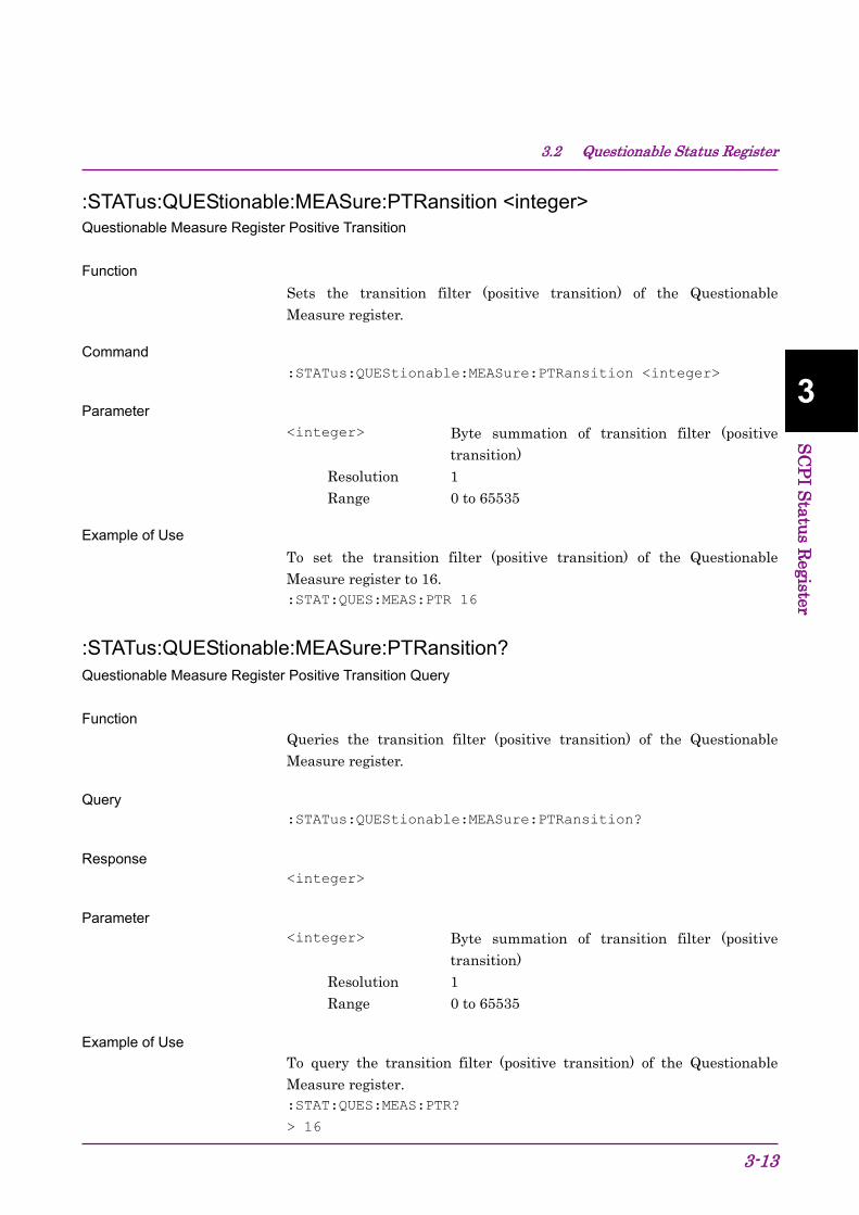
3.2 Questionable Status Register
3-13
3
SCPI Status Register
:STATus:QUEStionable:MEASure:PTRansition <integer> Questionable Measure Register Positive Transition Function
Sets the transition filter (positive transition) of the Questionable Measure register.
Command :STATus:QUEStionable:MEASure:PTRansition <integer>
Parameter <integer> Byte summation of transition filter (positive
transition) Resolution 1 Range 0 to 65535
Example of Use To set the transition filter (positive transition) of the Questionable Measure register to 16. :STAT:QUES:MEAS:PTR 16
:STATus:QUEStionable:MEASure:PTRansition? Questionable Measure Register Positive Transition Query Function
Queries the transition filter (positive transition) of the Questionable Measure register.
Query :STATus:QUEStionable:MEASure:PTRansition?
Response <integer>
Parameter <integer> Byte summation of transition filter (positive
transition) Resolution 1 Range 0 to 65535
Example of Use To query the transition filter (positive transition) of the Questionable Measure register. :STAT:QUES:MEAS:PTR?
> 16

Chapter 3 SCPI Status Register
3-14
3.3 Operation Status:Register Figure 3.3-1 and Table 3.3-1 show the layer structure of the Operation Status register.
CALibrating DB0 SETTling DB1 RANGing (NOT USED) DB2 SWEeping (NOT USED) DB3 MEASuring DB4 Wainting for TRIG DB5 Waiting for ARM (NOT USED) DB6 CORRecting (NOT USED) DB7 FILE Operating DB8 NOT USED DB9 NOT USED DB10 NOT USED DB11 NOT USED DB12 INSTrument (NOT USED) DB13 PROGram (NOT USED) DB14 NOT USED DB15
Status Byte Register DB7
Figure 3.3-1 Operation Status Register
Table 3.3-1 Bit Definition of Operation Status Register
Bit Definition DB0 Executing CAL DB1 Displaying Warm Up DB4 Analyzing DB5 Waiting for trigger DB8 Manipulating file
Table 3.3-2 lists the device messages for the Operation Status register.
These device messages are available only in SCPI mode.
Table 3.3-2 Device Messages for Operation Status Register
Function Device Message Operation Status Register Event :STATus:OPERation[:EVENt]?
Operation Status Register Condition :STATus:OPERation:CONDition?
Operation Status Register Enable :STATus:OPERation:ENABle <integer>
:STATus:OPERation:ENABle?
Operation Status Register Negative Transition
:STATus:OPERation:NTRansition <integer>
:STATus:OPERation:NTRansition?
Operation Status Register Positive Transition
:STATus:OPERation:PTRansition <integer>
:STATus:OPERation:PTRansition?

3.3 Operation Status:Register
3-15
3
SCPI Status Register
:STATus:OPERation[:EVENt]? Operation Status Register Event Function
Queries the event register of the Operation Status register.
Query :STATus:OPERation[:EVENt]?
Response <integer>
Parameter <integer> Byte summation of event register
Resolution 1 Range 0 to 65535
Example of Use To query the content of the event register of Operation Status register. :STAT:OPER?
> 0
:STATus:OPERation:CONDition? Operation Status Register Condition Function
Queries the condition register of the Operation Status Register.
Query :STATus:OPERation:CONDition?
Response <integer>
Parameter <integer> Byte summation of condition register
Resolution 1 Range 0 to 65535
Example of Use To query the content of the condition register of the Operation Status register. :STAT:OPER:COND?
> 0

Chapter 3 SCPI Status Register
3-16
:STATus:OPERation:ENABle <integer> Operation Status Register Enable Function
Sets the event enable register of the Operation Status register.
Command :STATus:OPERation:ENABle <integer>
Parameter <integer> Byte summation of event enable register
Resolution 1 Range 0 to 65535
Example of Use To set the event enable register of the Operation Status register to 16. :STAT:OPER:ENAB 16
:STATus:OPERation:ENABle? Operation Status Register Enable Query Function
Queries the event enable register of the Operation Status register.
Query :STATus:OPERation:ENABle?
Response <integer>
Parameter <integer> Byte summation of event enable register
Resolution 1 Range 0 to 65535
Example of Use To query the event enable register of the Operation Status register. :STAT:OPER:ENAB?
> 16

3.3 Operation Status:Register
3-17
3
SCPI Status Register
:STATus:OPERation:NTRansition <integer> Operation Status Register Negative Transition Function
Sets the transition filter (negative transition) of the Operation Status register.
Command :STATus:OPERation:NTRansition <integer>
Parameter <integer> Byte summation of transition filter (negative
transition) Resolution 1 Range 0 to 65535
Example of Use To set the transition filter (negative transition) of the Operation Status register to 16. :STAT:OPER:NTR 16
:STATus:OPERation:NTRansition? Operation Status Register Negative Transition Query Function
Queries the transition filter (negative transition) of the Operation Status register.
Query :STATus:OPERation:NTRansition?
Response <integer>
Parameter <integer> Byte summation of transition filter (negative
transition) Resolution 1 Range 0 to 65535
Example of Use To query the transition filter (negative transition) of the Operation Status register. :STAT:OPER:NTR?
> 16

Chapter 3 SCPI Status Register
3-18
:STATus:OPERation:PTRansition <integer> Operation Status Register Positive Transition Function
Sets the transition filter (positive transition) of the Operation Status register.
Command :STATus:OPERation:PTRansition <integer>
Parameter <integer> Byte summation of transition filter (positive
transition) Resolution 1 Range 0 to 65535
Example of Use To set the transition filter (positive transition) of the Operation Status register to 16. :STAT:OPER:PTR 16
:STATus:OPERation:PTRansition? Operation Status Register Positive Transition Query Function
Queries the transition filter (positive transition) of the Operation Status register.
Query :STATus:OPERation:PTRansition?
Response <integer>
Parameter <integer> Byte summation of transition filter (positive
transition) Resolution 1 Range 0 to 65535
Example of Use To query the transition filter (positive transition) of the Operation Status register. :STAT:OPER:PTR?
> 16

3.4 Utility
3-19
3
SCPI Status Register
3.4 Utility Table 3.4-1 lists the device messages for the Utility .
Table 3.4-1 Device Messages for Utility
Function Device Message Erase Warm Up Message :DISPlay:ANNotation:WUP:ERASe
Display Title :DISPlay:ANNotation:TITLe[:STATe] OFF|ON|0|1
:DISPlay:ANNotation:TITLe[:STATe]?
Title Entry :DISPlay:ANNotation:TITLe:DATA <string>
:DISPlay:ANNotation:TITLe:DATA?
:DISPlay:ANNotation:WUP:ERASe Erase Warm Up Message Function
Erases the warm-up message displayed immediately after startup.
Command :DISPlay:ANNotation:WUP:ERASe
Example of Use To query the transition filter (positive transition) of the Operation Status register. :DISP:ANN:WUP:ERAS

Chapter 3 SCPI Status Register
3-20
:DISPlay:ANNotation:TITLe[:STATe] OFF|ON|0|1 Display Title Function
Turns the title display on/off.
Command :DISPlay:ANNotation:TITLe[:STATe] <switch>
Parameter <switch> Title display On/Off
OFF|0 Off ON|1 On (Default)
Example of Use To display the title. :DISP:ANN:TITL ON
:DISPlay:ANNotation:TITLe[:STATe]? Display Title Query Function
Queries whether the title display is enabled/disabled.
Query :DISPlay:ANNotation:TITLe[:STATe]?
Response <switch>
Parameter <switch> Title display On/Off
0 Off 1 On
Example of Use To query the title display On/Off state. :DISP:ANN:TITL?
> 1

3.4 Utility
3-21
3
SCPI Status Register
:DISPlay:ANNotation:TITLe:DATA <string> Title Entry Function
Sets the title character string.
Command :DISPlay:ANNotation:TITLe:DATA <string>
Parameter <string> Character string within 32 characters enclosed
by double quotes (" ") or single quotes (' ')
Example of Use To set the title character string 'TEST'. :DISP:ANN:TITL:DATA 'TEST'
:DISPlay:ANNotation:TITLe:DATA? Title Entry Query Function
Queries the title character string.
Query :DISPlay:ANNotation:TITLe:DATA?
Response <string>
Parameter <string> Character string within 32 characters enclosed
by double quotes (" ") or single quotes (' ') Example of Use
To query the title character string. :DISP:ANN:TITL:DATA?
> TEST

Chapter 3 SCPI Status Register
3-22.
Related Documents