International Journal of Advances in Engineering & Technology, Nov 2011. ©IJAET ISSN: 2231-1963 89 Vol. 1, Issue 5, pp. 89-95 A NOVEL DESIGN FOR ADAPTIVE HARMONIC FILTER TO IMPROVE THE PERFORMANCE OF OVER CURRENT RELAYS A. Abu-Siada Department of Electrical and Computer Engineering, Curtin University, Perth, Australia ABSTRACT Due to the ever-increasing in non linear loads and the worldwide trend to establish smart grids, harmonic level in the electricity grids is significantly increased. In addition to their impact on power quality, harmonic current can have a devastating effect on the operation of over current relays as they are designed to operate efficiently at the fundamental frequency. The distorted waveform will affect the operation of the over current rely and may cause the relay to trip under normal operating conditions. To solve this problem, power passive and active filters are employed to eliminate the harmonics and purify the relay operational signal. Passive filters are not cost effective choice to solve this issue. On the other hand, active filters are more complex and need proper and complicated controller. This paper introduces a new and simple approach for adaptive filter design. This approach is economic, compact and very effective in eliminating harmonics in the grid. It can be easily attached with any protective relay to improve its performance. Application of this design to improve the performance of over current relays in the IEEE-30 bus system with heavy penetration of non-linear loads is investigated. KEYWORDS: Over current relay, harmonic filters, IEEE-30 bus system I. INTRODUCTION Most of the litratures reveal that the performance of relays in presence of harmonic currents is not significantly affected for total harmonic distortion (THD) less than 20% [1]. As there has been a tremendous increase in harmonic sources in the last few decades, harmonic levels of 20 % and higher are expected. Moreover overcurrent relays have to operate with current transformers which may saturate and distort the current waveform causing a relay to trip under conditions which would normally incur smooth running of the system without interruption [1-5]. Current transformer saturation may occur due to the presence of harmonics which may cause a current transformer failure to devliver a true reproduction of the primary current to the relay during fault conditions and thus may cause undesirable operations [6-8]. Electromechanical relays are nowadays considered obsolete in most of developing countries, however they are still used in some places. Electromechanical relays time delay characteristics are altered in the presence of harmonics. Another type of relays that is affected by harmonics is the negative-sequence overcurrent relay which is designed to specifically function with the negative sequence current component and it cannot perform upto its standard when there is a significant waveform distortion. Digital and numerical relays usually have built-in filters to filter out harmonics and thus are less prone to maloperation [9]. Active power filters which are more flexible and viable than passive filters have become popular nowadays [10]. However, active power filters configuration is more complex and require appropriate control devices to operate [11]. This paper introduces a novel active filter design that is compact, simple and reliable. Application of this design to improve the performance of over current relays in the IEEE-30 bus system with heavy penetration of non-linear loads is investigated.

Welcome message from author
This document is posted to help you gain knowledge. Please leave a comment to let me know what you think about it! Share it to your friends and learn new things together.
Transcript
International Journal of Advances in Engineering & Technology, Nov 2011.
©IJAET ISSN: 2231-1963
89 Vol. 1, Issue 5, pp. 89-95
A NOVEL DESIGN FOR ADAPTIVE HARMONIC FILTER TO
IMPROVE THE PERFORMANCE OF OVER CURRENT RELAYS
A. Abu-Siada Department of Electrical and Computer Engineering, Curtin University, Perth, Australia
ABSTRACT
Due to the ever-increasing in non linear loads and the worldwide trend to establish smart grids, harmonic level
in the electricity grids is significantly increased. In addition to their impact on power quality, harmonic current
can have a devastating effect on the operation of over current relays as they are designed to operate efficiently
at the fundamental frequency. The distorted waveform will affect the operation of the over current rely and may
cause the relay to trip under normal operating conditions. To solve this problem, power passive and active
filters are employed to eliminate the harmonics and purify the relay operational signal. Passive filters are not
cost effective choice to solve this issue. On the other hand, active filters are more complex and need proper and
complicated controller. This paper introduces a new and simple approach for adaptive filter design. This
approach is economic, compact and very effective in eliminating harmonics in the grid. It can be easily attached
with any protective relay to improve its performance. Application of this design to improve the performance of
over current relays in the IEEE-30 bus system with heavy penetration of non-linear loads is investigated.
KEYWORDS: Over current relay, harmonic filters, IEEE-30 bus system
I. INTRODUCTION
Most of the litratures reveal that the performance of relays in presence of harmonic currents is not
significantly affected for total harmonic distortion (THD) less than 20% [1]. As there has been a
tremendous increase in harmonic sources in the last few decades, harmonic levels of 20 % and higher
are expected. Moreover overcurrent relays have to operate with current transformers which may
saturate and distort the current waveform causing a relay to trip under conditions which would
normally incur smooth running of the system without interruption [1-5]. Current transformer
saturation may occur due to the presence of harmonics which may cause a current transformer failure
to devliver a true reproduction of the primary current to the relay during fault conditions and thus may
cause undesirable operations [6-8]. Electromechanical relays are nowadays considered obsolete in
most of developing countries, however they are still used in some places. Electromechanical relays
time delay characteristics are altered in the presence of harmonics. Another type of relays that is
affected by harmonics is the negative-sequence overcurrent relay which is designed to specifically
function with the negative sequence current component and it cannot perform upto its standard when
there is a significant waveform distortion. Digital and numerical relays usually have built-in filters to
filter out harmonics and thus are less prone to maloperation [9].
Active power filters which are more flexible and viable than passive filters have become popular
nowadays [10]. However, active power filters configuration is more complex and require appropriate
control devices to operate [11]. This paper introduces a novel active filter design that is compact,
simple and reliable. Application of this design to improve the performance of over current relays in
the IEEE-30 bus system with heavy penetration of non-linear loads is investigated.
International Journal of Advances in Engineering & Technology, Nov 2011.
©IJAET
The proposed filter design with the detailed circuit components is elaborated in section 2. To prove
the reliability of the proposed filter, the simulation results of two case studies are
3. Application of the proposed filter to the IEEE
draws the overall conclusion of the paper.
II. PROPOSED FILTER DESIGN
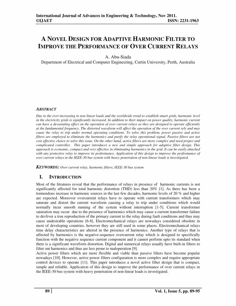
To purify the current signal received by the current transformer
which consists of a fundamental current
secondary side of the step down transformer is extracted and the fundamental current component is
filtered out using a narrow band rejected filter while the remaining harmonic components will be used
to cancel the harmonic components in the other path by using a shifting transformer
1. In this way the current signal fed to the rel
The overall circuit is shown in Fig. 2.
Fig
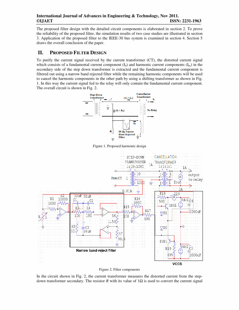
In the circuit shown in Fig. 2, the current transformer measures the distorted current from the step
down transformer secondary. The resistor
International Journal of Advances in Engineering & Technology, Nov 2011.
ISSN: 2231
The proposed filter design with the detailed circuit components is elaborated in section 2. To prove
the reliability of the proposed filter, the simulation results of two case studies are illustrated in section
3. Application of the proposed filter to the IEEE-30 bus system is examined in section 4. Section 5
draws the overall conclusion of the paper.
ESIGN
To purify the current signal received by the current transformer (CT), the distorted
current component (I0) and harmonic current components
secondary side of the step down transformer is extracted and the fundamental current component is
rejected filter while the remaining harmonic components will be used
to cancel the harmonic components in the other path by using a shifting transformer as
In this way the current signal fed to the relay will only contain the fundamental current
he overall circuit is shown in Fig. 2.
Figure 1. Proposed harmonic design
Figure 2. Filter components
In the circuit shown in Fig. 2, the current transformer measures the distorted current from the step
down transformer secondary. The resistor R with its value of 1Ω is used to convert the current signal
International Journal of Advances in Engineering & Technology, Nov 2011.
ISSN: 2231-1963
The proposed filter design with the detailed circuit components is elaborated in section 2. To prove
illustrated in section
30 bus system is examined in section 4. Section 5
he distorted current signal
components (Ihs) in the
secondary side of the step down transformer is extracted and the fundamental current component is
rejected filter while the remaining harmonic components will be used
as shown in Fig.
current component.
In the circuit shown in Fig. 2, the current transformer measures the distorted current from the step-
is used to convert the current signal
International Journal of Advances in Engineering & Technology, Nov 2011.
©IJAET ISSN: 2231-1963
to a voltage signal which is amplified by 10 times using an operational amplifier. The key component
of the active filter is the narrow band-reject 50 Hz filter which suppresses the 50Hz fundamental
component. The filter compresses low-pass and high-pass filter components with a summing amplifier
(twin-T notch filters). The filter transfer function and the value of its components are calculated based
on the required specifications. The output signal of the filter is amplified using an operational
amplifier and then is converted to a current signal (comprising harmonic components only) using a
voltage controlled current source (VCCS). The harmonic components are then fed to one terminal of
the cancellation transformer where the original current component (comprising fundamental and
harmonic components) is fed to another terminal for harmonic cancellation. In this way, a pure
fundamental current signal is guaranteed to be fed to the over current relay.
III. SIMULATION RESULTS
To examine the filter capability in suppressing all undesired current harmonics while retaining the
fundamental component, the circuit shown in Fig. 2 is simulated using PSIM software and 2 case
studies are performed.
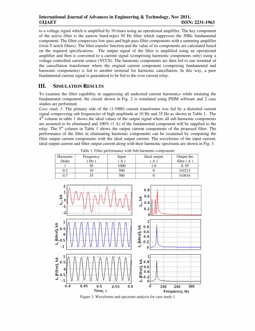
Case study 1: The primary side of the (1:1000) current transformer was fed by a distorted current
signal compressing sub frequencies of high amplitude at 10 Hz and 35 Hz as shown in Table 1. The
4th column in table 1 shows the ideal values of the output signal where all sub harmonic components
are assumed to be eliminated and 100% (1 A) of the fundamental component will be supplied to the
relay. The 5th column in Table 1 shows the output current components of the proposed filter. The
performance of the filter in eliminating harmonic components can be examined by comparing the
filter output current components with the ideal output current. The waveforms of the input current,
ideal output current and filter output current along with their harmonic spectrums are shown in Fig. 3.
Table 1. Filter performance with Sub-harmonic components
Harmonic
Order
Frequency
( Hz )
Input
( A )
Ideal output
( A )
Output the
filter ( A )
1 50 1000 1.0 0. 95
0.2 10 500 0 0.0213
0.7 35 500 0 0.0816
Figure 3. Waveforms and spectrum analysis for case study 1
International Journal of Advances in Engineering & Technology, Nov 2011.
©IJAET ISSN: 2231-1963
Table 2. Filter performance with sub-harmonic and harmonic components
Harmonic
Order
Frequency
( Hz )
Input
( A )
Ideal output
( A )
Output the
filter ( A )
1 50 1000 1.0 0. 9863
0.2 10 500 0 0.0101
0.6 30 500 0 0.3293
2 100 500 0 0.0102
3 150 500 0 0.0023
5 250 300 0 0.0079
7 350 300 0 0.0131
9 450 300 0 0.0055
11 550 100 0 0.0067
13 650 100 0 0.0079
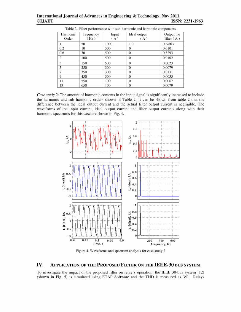
Case study 2: The amount of harmonic contents in the input signal is significantly increased to include
the harmonic and sub harmonic orders shown in Table 2. It can be shown from table 2 that the
difference between the ideal output current and the actual filter output current is negligible. The
waveforms of the input current, ideal output current and filter output currents along with their
harmonic spectrums for this case are shown in Fig. 4.
Figure 4. Waveforms and spectrum analysis for case study 2
IV. APPLICATION OF THE PROPOSED FILTER ON THE IEEE-30 BUS SYSTEM
To investigate the impact of the proposed filter on relay’s operation, the IEEE 30-bus system [12]
(shown in Fig. 5) is simulated using ETAP Software and the THD is measured as 3%. Relays
International Journal of Advances in Engineering & Technology, Nov 2011.
©IJAET ISSN: 2231-1963
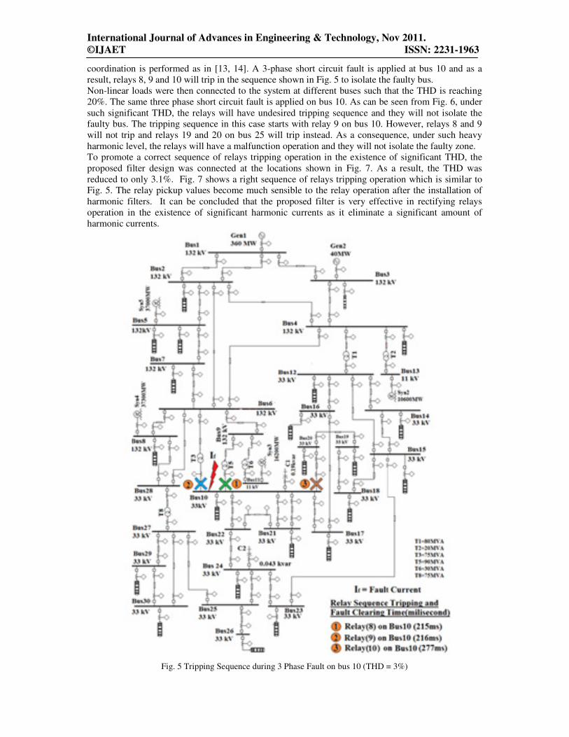
coordination is performed as in [13, 14]. A 3-phase short circuit fault is applied at bus 10 and as a
result, relays 8, 9 and 10 will trip in the sequence shown in Fig. 5 to isolate the faulty bus.
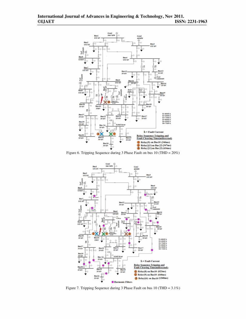
Non-linear loads were then connected to the system at different buses such that the THD is reaching
20%. The same three phase short circuit fault is applied on bus 10. As can be seen from Fig. 6, under
such significant THD, the relays will have undesired tripping sequence and they will not isolate the
faulty bus. The tripping sequence in this case starts with relay 9 on bus 10. However, relays 8 and 9
will not trip and relays 19 and 20 on bus 25 will trip instead. As a consequence, under such heavy
harmonic level, the relays will have a malfunction operation and they will not isolate the faulty zone.
To promote a correct sequence of relays tripping operation in the existence of significant THD, the
proposed filter design was connected at the locations shown in Fig. 7. As a result, the THD was
reduced to only 3.1%. Fig. 7 shows a right sequence of relays tripping operation which is similar to
Fig. 5. The relay pickup values become much sensible to the relay operation after the installation of
harmonic filters. It can be concluded that the proposed filter is very effective in rectifying relays
operation in the existence of significant harmonic currents as it eliminate a significant amount of
harmonic currents.
Fig. 5 Tripping Sequence during 3 Phase Fault on bus 10 (THD = 3%)
International Journal of Advances in Engineering & Technology, Nov 2011.
©IJAET ISSN: 2231-1963
Figure 6. Tripping Sequence during 3 Phase Fault on bus 10 (THD = 20%)
Figure 7. Tripping Sequence during 3 Phase Fault on bus 10 (THD = 3.1%)
International Journal of Advances in Engineering & Technology, Nov 2011.
©IJAET ISSN: 2231-1963
V. CONCLUSION
Simulation results show that, when the THD is more than 20%, the over current relay’s performance
is significantly affected and a malfunction will be caused. When a fault occurs in the system, the over
current relay will not be able to isolate the faulty location as they will trip in an undesired way.
Reducing THD to a level below 20% will mitigate this problem and a proper relay’s operation can be
retained. Passive harmonic filters are not a cost effective solution to solve this problem. The proposed
filter design is very effective in reducing the THD in the system to almost negligible level and will
rectify relays operation in the existence of significant harmonic currents. The proposed filter is
compact, cost effective, technically sound and easy to be implemented.
REFERENCES
[1] Tumiran, T. Haryono and Zulkarnaini, “Effect of Harmonic Loads on Over Current Relay to Distribution
System protection”, Proceeding of the International Conference on Electrical Engineering and Informatics June
2007
[2] N.X. Tung, G. Fujita, M.A.S Masoum, S.M Islam, “Impact of harmonics on Tripping time and Coordination
of Overcurrent Relay”, 7th
WSEAS International Conference on Electric Power Systems, High Voltages,
Electric Machines, Venice, Italy, November, 2007
[3] A.wright and C.christopoulos, Electrical power system protection, London: Chapman & Hall, 1993
[4] S. Arrillaga, Watson and Wood, Power system harmonics, England: John Wiley & Sons Ltd, 1997.
[5] A. Watson, Power system harmonics, England: John Wiley & Sons Ltd, 2003.
[6] N.A Abbas, “Saturation of current transformers and its impact on digital Over current relays” Msc Thesis,
King Fahd University of Petroleum and Minerals, Dahrain, Saudi Arabia, August 2005
[7] F. M. A. S. M. Elwald F, Power Quality in Power Systems and Electrical Machines, Amsterdam and
Boston: Academic Press/Elsvier, 2008.
[8] Francisco C. De La rosa.”Effect of harmonic distortion on power systems” in Harmonics and Power
Systems. Boca Raton, FL : CRC/Taylor & Francis, 2006.
[9] A. A. Girgis, J. W. Nims, J. Jacamino, J. G. Dalton, and A. Bishop, "Effect of voltage harmonics on the
operation of solid state relays in industrial applications," in Industry Applications Society Annual Meeting,
1990., Conference Record of the 1990 IEEE, 1990, pp. 1821-1828 vol.2.
[10] C. Cheng-Che and H. Yuan-Yih, "A novel approach to the design of a shunt active filter for an unbalanced
three-phase four-wire system under nonsinusoidal conditions," Power Delivery, IEEE Transactions on, vol. 15,
pp. 1258-1264, 2000.
[11] G.J Wakileh, Power system harmonics fundamental analysis and filter design, Berlin ; New York
: Springer, 2001
[12] H. Saadat, Power System Analysis, New York: McGraw-Hills Inc., 2002.
[13] M. Ezzeddine, R. Kaczmarek, and M. U. Iftikhar, "Coordination of directional overcurrent relays using a
novel method to select their settings," Generation, Transmission & Distribution, IET, vol. 5, pp. 743-750.
[14] D. Birla, R. P. Maheshwari, and H. O. Gupta, "A new nonlinear directional overcurrent relay coordination
technique, and banes and boons of near-end faults based approach," Power Delivery, IEEE Transactions on, vol.
21, pp. 1176-1182, 2006.
Author
A. Abu-Siada (M’07) received his B.Sc. and M.Sc. degrees from Ain Shams University,
Egypt and the PhD degree from Curtin University of Technology, Australia, All in
Electrical Engineering. Currently, he is a lecturer in the Department of Electrical and
Computer Engineering at Curtin University. His research interests include power system
stability, Condition monitoring, Superconducting Magnetic Energy Storage (SMES), Power
Electronics, Power Quality, Energy Technology, and System Simulation. He is a regular
reviewer for the IEEE Transaction on Power Electronics, IEEE Transaction on Dielectrics
and Electrical Insulations, and the Qatar National Research Fund (QNRF).
Related Documents


![i .] APPROXIMATING HARMONIC FUNCTIONS 499€¦ · APPROXIMATING HARMONIC FUNCTIONS 499 THE APPROXIMATION OF HARMONIC FUNCTIONS BY HARMONIC POLYNOMIALS AND BY HARMONIC RATIONAL FUNCTIONS*](https://static.cupdf.com/doc/110x72/5f0873ba7e708231d42214c2/i-approximating-harmonic-functions-499-approximating-harmonic-functions-499-the.jpg)