JOURNAL OF GEOPHYSICAL RESEARCH,VOL. 89, NO. B12, PAGES 10,249-10,266, NOVEMBER 10, 1984 ANOMALOUSLY THIN CRUST IN OCEANIC FRACTURE ZONES: NEW SEISMIC CONSTRAINTS FROM THE KANE FRACTURE ZONE Marie-Helene Cormier and Robert S. Detrick Graduate School of Oceanography, University of Rhode Island, Narragansett G. Michael Purdy Woods Hole Oceanographic Institution, Massachusetts Abstract. Three detailed and carefully positioned seismic refraction experiments have recently been carried out along the Kane fracture zone near 24øN, 44ow in order to place better geophysical constraints on the extent and origin of the anomalously thin crust reported from parts of this and other large Atlantic fracture zones. These three experiments, when combined with earlier studies, result in reversed Structural control along about a 300-km-long segment of the Kane fracture zone extending from the ridge- transform intersection out onto crust about 25 m.y. old. An analysis of refraction lines obtained along the fracture zone trough by using both travel time modeling and delay time function techniques reveals large variations in crustal Introduction It has been recognized for many years that the walls bordering many large Atlantic fracture zones (e.g., Oceanographer, Vema, Romanche,Kane) expose a diverse suite of gabbroic and ultramafic rocks that are not commonly found elsewhere in the ocean basins. Francheteau et al. [1976] suggested that these rocks, which are generally associated with the lower crust and upper mantle, are exposed in fracture zones as a result of the presence of an anomalously thin volcanic layer. On the basis of observations made from the submersible CYANA during traverses across Transform A in the FAMOUS area [ARCYANA, 1975], they noted that the great relief of fracture zone escarpments is actually thickness and/or velocity. However, along most of produced by a large number of small-throw faults the eastern fracture zone trough, upper mantle- whose offsets (typically less than 100 m) would type velocitie• are found at depths of only 2-3 km limit the possible exposure of lower crustal rocks below the seafloor, less than half. the typical if a normal thickness crustal section (5-7 km depth to Moho in the ocean basinS. •This anomalous thick) is present. Francheteau et al. [1976] fracture zone crust is generally characterized by argued that either the shallow intrusive and unusually low compressional wave velocities, extrusive carapace is very thin in fracture zones relatively high-velocity gradients throughout most or the crust must be tectonically thinned by of the thinned crustal section (about 1-2 s-1) and faulting within the transform domain. Recent a distinct crust-mantle boundary. The very thin crust appears to be confined to the deepest parts of the Kane fracture zone trough (<10 km wide), although a more gradual crustal thinning may extend up to several tens of kilometers from the fracture zone. A specially designed delay time experiment at the intersection of the Kane fracture zone and the Mid-Atlantic Ridge also submersible studies of several ridge-transform intersections [CAYTROUGH, 1979; Stroup and Fox, 1981; Karson and Dick, 1983; OTTER Scientific Team, 1984a] and a portion of the Oceanographer transform [OTTER Scientific Team, 1984b] have confirmed the ubiquitous exposure of gabbroic and ultramafic rocks on the many small-throw faults forming transform valley walls, leading a number revealed the presence of a thinned crustal section of investigators to suggest that the total crustal of a relatively uniform thickness (about 3 km) section created near transforms is extremely thin except beneath the nodal basin where the crust may [Fox, 1978; CAYTROUGH, 1979; Stroup and Fox, 1981• be less than 1 km thick. The ano'malous crust in the intersection area appears to extend at least part way dOWn•the median valley. We interpret this anomalous fracture zone crust as a primary accretionarY feature that fokms as a result of a restricted magma supply near ridge•transform intersections, although tectonic processes may also play a part, at least locally, in thinning the crust. Our results support a "ribbon" model Karson and Dick, 1983; OTTER Scientific Team, 1984a]. Some of the best seismic constraints on fracture zone crustal structure have come from refraction experiments at the Kane [Detrick and Purdy, 1980] and Oceanographer [Sinha and Louden, 1983] fracture zones, two large, central North Atlantic fracture zones. These experiments found upper mantle-type velocities (7.7-8.1 km/s) along of the gross seismic structure of the ocean basins parts of both fracture zones at depths of only 2-3 in which bands of relatively homogeneous, so- km below the seafloor, less than half the typical called normal crust 50-100 km wide extend away depth to Moho in the ocean basins. This anomalous from spreading centers, each formed at a discrete fracture zone crust was characterized by unusually ridge crest segment and each separated by the thin low seismic velocities, a relatively uniform crust underlying the fracture zone trough. Copyright 1984 by the American Geophysical Union. Papern•mber 4B0988. 0148-0227/84/004B-0988505.00 velocity gradient throughout most of the thinned crustal section, and the absence of a typical layer 3 refractor. This unusually thin crust is apparently confined to a relatively narrow zone centered on the fracture zone trough, although its lateral extent is not well constrained by these seismic refraction experiments. An additional, 10,249

Welcome message from author
This document is posted to help you gain knowledge. Please leave a comment to let me know what you think about it! Share it to your friends and learn new things together.
Transcript
JOURNAL OF GEOPHYSICAL RESEARCH, VOL. 89, NO. B12, PAGES 10,249-10,266, NOVEMBER 10, 1984
ANOMALOUSLY THIN CRUST IN OCEANIC FRACTURE ZONES:
NEW SEISMIC CONSTRAINTS FROM THE KANE FRACTURE ZONE
Marie-Helene Cormier and Robert S. Detrick
Graduate School of Oceanography, University of Rhode Island, Narragansett
G. Michael Purdy
Woods Hole Oceanographic Institution, Massachusetts
Abstract. Three detailed and carefully positioned seismic refraction experiments have recently been carried out along the Kane fracture zone near 24øN, 44ow in order to place better geophysical constraints on the extent and origin of the anomalously thin crust reported from parts of this and other large Atlantic fracture zones. These three experiments, when combined with earlier studies, result in reversed Structural control along about a 300-km-long segment of the Kane fracture zone extending from the ridge- transform intersection out onto crust about 25
m.y. old. An analysis of refraction lines obtained along the fracture zone trough by using both travel time modeling and delay time function techniques reveals large variations in crustal
Introduction
It has been recognized for many years that the walls bordering many large Atlantic fracture zones (e.g., Oceanographer, Vema, Romanche, Kane) expose a diverse suite of gabbroic and ultramafic rocks that are not commonly found elsewhere in the ocean basins. Francheteau et al. [1976] suggested that these rocks, which are generally associated with the lower crust and upper mantle, are exposed in fracture zones as a result of the presence of an anomalously thin volcanic layer. On the basis of observations made from the submersible CYANA
during traverses across Transform A in the FAMOUS area [ARCYANA, 1975], they noted that the great relief of fracture zone escarpments is actually
thickness and/or velocity. However, along most of produced by a large number of small-throw faults the eastern fracture zone trough, upper mantle- whose offsets (typically less than 100 m) would type velocitie• are found at depths of only 2-3 km limit the possible exposure of lower crustal rocks below the seafloor, less than half. the typical if a normal thickness crustal section (5-7 km depth to Moho in the ocean basinS. •This anomalous thick) is present. Francheteau et al. [1976] fracture zone crust is generally characterized by argued that either the shallow intrusive and unusually low compressional wave velocities, extrusive carapace is very thin in fracture zones relatively high-velocity gradients throughout most or the crust must be tectonically thinned by of the thinned crustal section (about 1-2 s -1) and faulting within the transform domain. Recent a distinct crust-mantle boundary. The very thin crust appears to be confined to the deepest parts of the Kane fracture zone trough (<10 km wide), although a more gradual crustal thinning may extend up to several tens of kilometers from the fracture zone. A specially designed delay time experiment at the intersection of the Kane fracture zone and the Mid-Atlantic Ridge also
submersible studies of several ridge-transform intersections [CAYTROUGH, 1979; Stroup and Fox, 1981; Karson and Dick, 1983; OTTER Scientific Team, 1984a] and a portion of the Oceanographer transform [OTTER Scientific Team, 1984b] have confirmed the ubiquitous exposure of gabbroic and ultramafic rocks on the many small-throw faults forming transform valley walls, leading a number
revealed the presence of a thinned crustal section of investigators to suggest that the total crustal of a relatively uniform thickness (about 3 km) section created near transforms is extremely thin except beneath the nodal basin where the crust may [Fox, 1978; CAYTROUGH, 1979; Stroup and Fox, 1981• be less than 1 km thick. The ano'malous crust in
the intersection area appears to extend at least part way dOWn•the median valley. We interpret this anomalous fracture zone crust as a primary accretionarY feature that fokms as a result of a restricted magma supply near ridge•transform intersections, although tectonic processes may also play a part, at least locally, in thinning the crust. Our results support a "ribbon" model
Karson and Dick, 1983; OTTER Scientific Team, 1984a].
Some of the best seismic constraints on
fracture zone crustal structure have come from
refraction experiments at the Kane [Detrick and Purdy, 1980] and Oceanographer [Sinha and Louden, 1983] fracture zones, two large, central North Atlantic fracture zones. These experiments found upper mantle-type velocities (7.7-8.1 km/s) along
of the gross seismic structure of the ocean basins parts of both fracture zones at depths of only 2-3 in which bands of relatively homogeneous, so- km below the seafloor, less than half the typical called normal crust 50-100 km wide extend away depth to Moho in the ocean basins. This anomalous from spreading centers, each formed at a discrete fracture zone crust was characterized by unusually ridge crest segment and each separated by the thin low seismic velocities, a relatively uniform crust underlying the fracture zone trough.
Copyright 1984 by the American Geophysical Union.
Paper n•mber 4B0988. 0148-0227/84/004B-0988505.00
velocity gradient throughout most of the thinned crustal section, and the absence of a typical layer 3 refractor. This unusually thin crust is apparently confined to a relatively narrow zone centered on the fracture zone trough, although its lateral extent is not well constrained by these seismic refraction experiments. An additional,
10,249
10,250 Cormier et al.: Thin Crust in the Kane Fracture Zone
more gradual crustal thinning appears to extend up clearly delineated by the 4000-m bathymetric to several tens of kilometers from the contour (Figure 1). Magnetic anomalies identified Oceanographer fracture zone [Sinha and Louden, on both flanks of the Mid-Atlantic Ridge north and 1983], while at the Kane fracture zone, thin crust south of the Kane indicate an age offset across may also extend beneath a 200-km-long ridge (Kane the fracture zone of 10 + 1 m.y. [Loud•n and Fracture Zone Ridge) which forms the northern wall Forsyth, 1982]. The ridge segment north of the of the fracture zone just east of its intersection Kane has been symmetrically spreading at a 14 with the Mid-Atlantic Ridge [Detrick and Purdy, 1980; Louden and Forsyth, 1982].
Although the existence of anomalously thin crust along parts of several oceanic fracture zones is fairly well documented [White et al., 1984], few data constrain its extent or possible structural variability at a more regional scale. Several lines of evidence suggest that this
mm/yr half rate, while magnetic anomalies to the south indicate a consistent east-west asymmetry in spreading: 11 mm/yr to the east and 17 m•/yr to the west [Schouten et al., 1979].
The Kane fracture zone itself is confined to a
narrow valley generally less than'•20 km wide and about 1000 m deeper than the surrounding seafloor. The f•oor of this trough is very ruggedland is
anomalous crust may be quite common; however, more marked by several elongate, en echelon, closed- normal crustal thicknesses of 4.5-5 km have been
observed along parts of both the Vema [Ludwig and Rabinowitz, 1980; Detrick et al., 1982] and Oceanographer [Sinha and Louden, 1983] fracture zones. At the Kane fracture zone the crustal
structure is also complicated by the presence of the Kane Fracture Zone Ridge. Similar ridges
contou• depressions and intervening ridges (Figure 1). •n the surveyed area the fracture'•zone valley lacks,•any significant accumulation of sediment, but talus from rock debris slides are common , especially in the active transform •egmed• [Karson and Dick, 1983]. Near both ridge-tranSfOrm intersections the northern and southern rift
along parts of other large Atlantic fracture zones valleys broaden and deepen into nodal basins in have been interpreted as uplifted blocks of crustal and upper mantle material [Bonatti, 1976, 1978]. If the Kane Fracture Zone Ridge has a similar origin, it is possible that the anomalous crustal structure observed by Detrick and Purdy [1980] is related to the emplacement of this feature and not typical of the rest of the fracture zone. On the other hand, if this
the intersection areas (Figure 1). At the eastern ridge-transform intersection this nodal basin is about 15 km wide and reaches depths in excess of 6000 m, one of the deepest points in the North Atlantic. Along part of the (older) north wall of the eastern Kane fracture zone is a prominent ridge (Kane Fracture Zone Ridge) which stands up to 1000 m higher than the surrounding seafloor.
anomalous crust is a common feature along the Kane Although bathymetric coverage is incomplete, it and other large Atlantic fracture zones, a more fundamental origin is likely, possibly involving an alteration in normal accretionary processes near ridge-transform intersections.
Here we report a series of seismic refraction experiments conducted at the Kane fracture zone in February 1982 which were designed to determine the seismic crustal structure along a significant length of a typical, large Atlantic fracture zone. We had three main objectives: (1) to determine whether the thin crust previously observed at the
does not appear to be a continuous ridge as much as a series of equant to elongate hills aligned along the edge of the fracture zone wall. This ridge extends from the eastern ridge-transform intersection at least 200 km to the east.
The Experiments
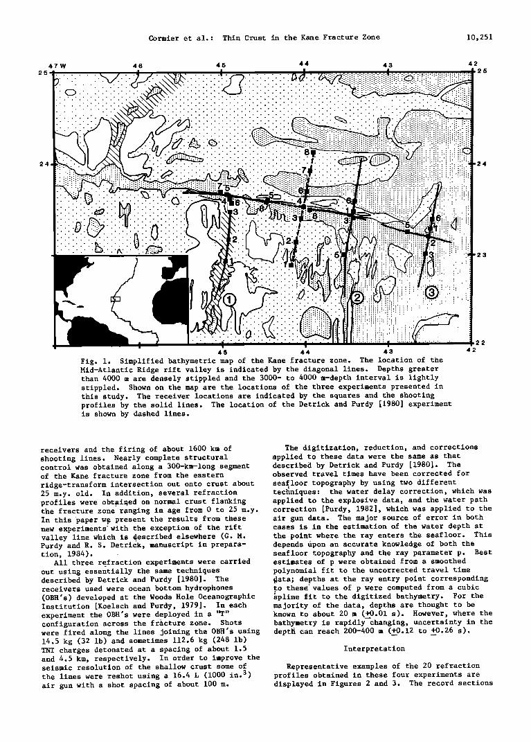
The three seismic refraction experiments reported here were located mainly along the inactive portion of the Kane fracture zone, east
Kane fracture zone is a common feature or confined of its intersection with the Mid-At•antic Ridge to a few isolated locations, (2) to determine the rift valley (Figure 1). These experiments were seismic structure north and south of the Kane and positioned so as to extend and complement the 1977 document how far the anomalous crust extends from refraction experiment conducted at about 44øW by the fracture zone, and (3) to place constraints on Detrick and Purdy [1980] in which crust only 2-3 the crustal structure of two tectonically complex features: the eastern ridge-transform inter- section and the Kane Fracture Zone Ridge.
The Kane Fracture Zone
The Kane fracture zone is a major slowly slipping transform that offsets the Mid-Atlantic Ridge rift valley near 24øN about 160 km in a left-lateral sense (Figure 1). It is one of the best studied fracture zones in the North Atlantic
and has been described in detail in a number of
km thick was found beneath the fracture zone
trough. The first experiment (labeled 1 in Figure 1) was aimed at determining the crustal structure in the ridge-transform intersection area and along the eastern portion of the transform valley. In addition, a 150-km-long line was shot down the median valley of the Mid-Atlantic Ridge south of the Kane fracture zone. The two easternmost
experiments (labeled 2 and 3 in Figure 1) were designed to determine if the anomalously thin crust found at 44øW is present only adjacent to the Kane Fracture Zone Ridge (experiment 2) or
other publications [Fox et al., 1969; Miyashiro et whether it also extends into the older part of the al., 1969, 1971; Fox, 1972; Rabinowitz and Purdy, fracture zone (experiment 3). Specially designed 1976; Purdy et al., 1979; Schouten et al., 1979; •etay time experiments were also carried out at Detrick and Purdy, 1980; Louden and Forsyth, 1982, the eastern ridge-transform intersection and along Karson and Dick, 1983]. Morphologically and the Kane Fracture Zone Ridge in order to constrain tectonically, the Kane fracture zone appears to be better the crustal structure near these features. typical of many large-offset, slowly slipping Altogether, these three new experiments and the transforms. earlier work of Detrick and Purdy [1980] provide
Near the Mid-Atlantic Ridge the Kane fracture extensive geophysical coverage of the Kane frac- zone has a regional trend of about i00 ø and is ture zone, representing the deployment of 26
Cormier et al.: Thin Crust in the Kane Fracture Zone 10,251
25
24
47W
ß .
.¸
46 45 44 43 42 25
ß ,
ß . . ........................
ß . . .................... ß .
ß .
......... ß .
........
.............
45 44 43
Fig. i. Simplified bathymetric map of the Kane fracture zone. The location of the Mid-Atlantic Ridge rift valley is indicated by the diagonal lines. Depths greater than 4000 m are densely stippled and the 3000- to 4000 m-depth interval is lightly stippled. Shown on the map are the locations of the three experiments presented in this study. The receiver locations are indicated by the squares and the shooting profiles by the solid lines. The location of the Detrick and Purdy [1980] experiment is shown by dashed lines.
..............
42
receivers and the firing of about 1600 km of shooting lines. Nearly complete structural control was obtained along a 300-km-long segment of the Kane fracture zone from the eastern
ridge-transform intersection out onto crust about 25 m.y. old. In addition, several refraction
The digitization, reduction, and corrections applied to these data were the same as that described by Detrick and Purdy [1980]. The observed travel times have been corrected for seafloor topography by using two different techniques: the water delay correction, which was
profiles were obt•ai•ed on normal crust flanking applied to the explosive data, and the water path the fracture zone ranging in age from 0 to 25 m.y. correction [Purdy, 1982], which was applied to the In this •paper w• present the results from these new experiments•with the exception of the rift valley line which is •escribed elsewhere (G. M. Purdy and R. S. Detrick, manuscript in prepara- tion, 1984). ,
All three refraction experiments were carried out using essentially the same techniques described by Detrick and Purdy [1980]. The receivers used were ocean bottom hydrophones (OBH's) developed at the Woods Hole Oceanographic Institution [Koelsch and Purdy, 1979]. In each experiment the OBH's were deployed in a "T"
air gun data. The major source of error in both cases is in the estimation of the water depth at the point where the ray enters the seafloor. This depends •pon an accurate knowledge of both the seafloor topography and the ray parameter p. Best estimates of p were obtained from a smoothed polynomial fit to the uncorrected travel time •ata; depths at the ray entry point corresponding to thes•values of p were computed from a cubic •pline fit to the digitized bathymetry. For the majority of the data, depths are thought to be known to about 20 m (+0.01 s). However, where the
configuration across the fracture zone. Shots bathymetr• is rapidly changing, uncertainty in the were fired along the lines joining the OBH's using dept• can reach 200-400 m (+_0.12 to _+0.26 s). 14.5 kg (32 lb) and sometimes 112.6 kg (248 lb) TNT charges detonated at a spacing of about 1.5 Interpretation and 4.5 km, respectively. In order to improve the seismic resolution of the shallow crust some of Representative examples of the 20 refraction the lines were reshot using a 16.4 L (1000 in. 3) profiles obtained in these four experiments are air gun with a shot spacing of about 100 m. displayed in Figures 2 and 3. The record sections
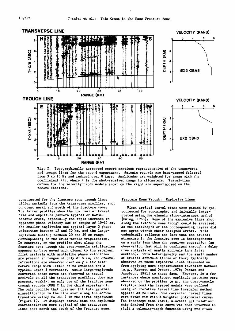
10,252 Cormier et al.: Thin Crust in the Kane Fracture Zone
TRANSVERSE LINE
• 6
"• 4- I- 13. LU
I• 6-
8-
VELOCITY (KM/S)
2 4 6 8 ß
EX20B
TROUGH LINE
• 6
10 20 30 40 50
RANGE (KM)
0 10 20 30 40 50
RANGE (KM)
o
-i- 4-
n uJ
• 6-
8-
VELOCITY (KM/S)
2 4 6
EX20BH3
Fig. 2. Topographically corrected record sections representative of the transverse and trough lines for the second experiment. Seismic records are band-passed filtered from 3 to 15 Hz and reduced over 8 km/s. Amplitudes are weighted for range with the coefficient X/5, where X is the shot-receiver range in kilometers. Travel-time curves for the velocity-depth models shown on the right are superimposed on the record sections.
8
constructed for the fracture zone trough lines Fracture Zone Trough: Explosive Lines differ markedly from the transverse profiles, shot • on crust north and south of the fracture zone. First arrival travel times were picked by eye, The latter profiles show the now familar travel corrected for topography, and initially inter- time and amplitude pattern typical of normal preted using the classic slope-intercept method oceanic crust, especially the rapid increase in [Ewing, 1963]. None of the explosive lines shot apparent phase velocity out to ranges of 10-15 km, along the fracture zone trough could be reversed, the smaller amplitudes and typical layer 3 phase as the intercepts of the corresponding layers did velocities between 15 and 20 km, and the large- not agree within their assigned errors. This amplitude buildup between 20 and 30 km range undoubtedly reflects the fact that the crustal corresponding to the crust-mantle triplication. structure in the fracture zone is heterogeneous In contrast, on the profiles shot along the on a scale le•s than the receiver separation (an fracture zone trough the crust-mantle triplication observation that will be confirmed through a delay appears to have moved much closer to the receiver, time analysis of mantle arrivals in a later first arrivals with mantlelike phase velocities section). This heterogeneity and the small number are present at ranges of only 8-15 km, and crustal of crustal arrivals (three or four) typically refractions are observed over only a few kilo- meters range with little or no evidence for a typical layer 3 refractor. While large-amplitude converted shear waves are observed as second
arrivals on all the transverse profiles, they are present, weakly, on only one of the fracture zone trough records (OBH 2 in the third experiment). The only profile that does not fit this general classification is the line shot along the active
observed on these explosive lines dissuaded us from applying more sophisticated inversion methods [e.g., Kennett and Orcutt, 1976; Dorman and Jacobson, 1981] to these data. However, in a few instances where consistent amplitude patterns were observed on the profiles (e.g., the crust-,mantle triplication) the layered models were refined using an iterative travel time inversion method applied as follows. The corrected travel times
transform valley to OBH 7 in the first experiment were first fit with a weighted polynomial curve. (Figure 1). It displays travel time and amplitude The intercept time (tau), slowness (p) relation- characteristics more typical of the transverse ship derived from this curve was then inverted to lines shot north and south of the fracture zone. yield a velocity-depth function using the T-sum
Cormier et al.: Thin Crust in the Kane Fracture Zone 10,253
TRANSVERSE LINE
X
I- 2
....... i ._ ß
ß i ! ß
0 10 20 30 40 50
RANGE (KM) TROUGH LINE
• 2
ß 'r' 4 I-- 13.
•3 6
0
'1- 4- I-- 13.
C3 6
8
VELOCITY (KM/S) 2 4 6 8
EX30BH6 I
VELOCITY (KM/S)
2 4 6 8 i I i I
EX30BH2
RANGE (KM)
Fig. 3. Topographically corrected record sections representative of the transverse and trough lines for experiment 3. Otherwise, the same as for Figure 2.
inversion method of Diebold and Stoffa [1981]. The average crustal thickness is 5.0 km, in the The velocity of the uppermost crust, from which no lower range of typical values. There is no arrivals were observed, was represented by a significant age-dependent variation in crustal single linear velocity gradient applying the structure apparent in these profiles. method described by Ewing and Purdy [1982]. Using In contrast, 10 of the 11 fracture zone trough the velocity depth model derived from this inver- lines fall well outside the range of velocity sion, travel time distance curves were calculated structures typically observed for oceanic crust in and compared to the observed travel time picks the North Atlantic. The most remarkable feature including any second arrivals. The velocity model of this anomalous fracture zone crust is that was then perturbed until a satisfactory fit was obtained to both the first and the second
arrivals.
The velocity-depth profiles derived for the 11 fracture zone trough lines and the 9 refraction profiles located on crust north and south of the Kane fracture zone are shown in Figure 4, where they are compared with the range of structures
total crustal thicknesses are only 2-3 km, about half the thickness of the crust on either side of
the fracture zone. The presence of this anomal- ously thin crust is well constrained both by the observation of arrivals with mantle-type phase velocities at unusually small shot-receiver ranges and the presence of a large-amplitude buildup at the 8-12 km range that appears to be associated
observed for "normal" oceanic crust. These latter with the crust-mantle triplication. The latter bounds were derived from a compilation by White observation indicates the existence of a rela- [1984] of all available velocity solutions, tively distinct crust-mantle transition beneath constrained by synthetic seismogram modeling, that the fracture zone despite the presence of an have been determined for crust in the North
Atlantic older than 2 m.y. Figure 4 emphasizes the striking partition of
our results between the anomalous fracture zone
crust and the more normal crustal structure
present on either side of the fracture zone. All the velocity depth solutions for the transverse lines lay within the bounds of typical oceanic crust in the North Atlantic. They show a steep velocity gradient in the upper 2-3 km underlain by a 2-3 km layer with velocities of 6.5-7.2 km/s.
unusually thin crustal section. Thus two of our primary observations are that
(1) upper mantle-type velocities are observed at extremely shallow depths beneath the fracture zone trough and (2) this anomalously thin crust is a very common feature along the Kane fracture zone and is not restricted to a few isolated locations
along the fracture zone (e.g., only adjacent to the Kane Fracture Zone Ridge).
Crustal velocities in the fracture zone are
also lower than usual. The average crustal
10,254 Cormier et al.: Thin Crust in the Kane Fracture Zone
O
1
'1"4 I-- Q. U,I 5
6
7
8
VELOCITY (KM/S) 2 3 4 5 6 7 8 9
1
6
7
8
VELOCITY (KM/S) 2 3 4 5 6 7 8 9
ß ß _ ß i i ß ß
i
i• -
Fig. 4. Velocity-depth solutions derived for the 11 fracture zone trough lines (left) and the 9 refraction profiles located north and south of the Kane fracture zone (right). The trough solutions as based on data from Detrick and Purdy [1980] (OBH 4 and OBH 5); experiment 1 (OBH 8); experiment 2 (OBH 3, explosive line and both sides of the split air gun profile, and OBH 8); experiment 3 (OBH 2 and OBH 5, west profile). The transverse solutions include data from Detrick and Purdy [1980] (OBH 1, OBH 2 (north profile), OBH 3, OBH 7 (south profile), and OBH 8)• experiment 2 (OBH 5 and OBH 6); experiment 3 (OBH 3 and OBH 6). Dashed lines are the velocity-depth solutions reported by Detrick and Purdy [1980]. For comparison the bounds on typical oceanic crustal structure observed in the North Atlantic [from White, 1984] are indicated by the diagonal lines.
velocity for the 10 anomalous Kane fracture zone profiles is 5.0 km/s compared to 6.2 km/s for the transverse lines. One consequence of these low crustal velocities is that despite an almost twofold difference in apparent crustal thickness, the mantle arrivals on the fracture zone trough profiles are not significantly earlier than those on the transverse lines. The fracture zone crust
is also unusual in that a refractor with a
velocity typical of oceanic layer 3 is rarely observed. This observation is particularly significant in that layer 3 is the most consistently observed feature of the seismic structure of the oceanic crust.
One notable exception to the pattern described above is a line shot along the transform valley west of OBH 7 (Figure 1). The record section constructed for this receiver displays a crustal refraction with a phase velocity of 6.5 km/s, a
well-developed crust-mantle triplication at 24 km range and, at greater ranges, clear mantle arrivals with a phase velocity of 8.1 km/s (Figure 5). A simple travel time analysis of this record section yields a seismic structure more typical of the transverse lines with an apparent crustal thickness of 6-7 km. This shooting line was run twice, and both profiles display similar characteristics giving us considerable confidence that the travel time and amplitude patterns we have observed are real. We are also confident
that this line was not inadvertently located outside of the fracture zone; ANGUS/Alvin results from the ridge-transform intersection area near OBH 7 [Karson and Dick, 1983] and a recent GLORIA survey of the Kane fracture zone (W. R. Roest et al., unpublished manuscript, 1984) both indicated that this line was shot along what appears to be the principal transform deformation zone within
6
0 10 2o 3o 4o
RANGE (KM)
A 2
VELOCITY (KM/S)
0 2 4 6 8
3
Fig. 5. Topographically corrected profile for OBH 7 in experiment 1, situated in the active transform. Bathymetry along the shooting line is plotted beneath the record section. Otherwise, same as for Figure 2.
Cormier et al.: Thin Crust in the Krone Fracture Zone 10,255
½' •1 OBH3 EX2
o; 0 '• • • 4 5 • •' • • 10 1
RANGE (KM) •:4
5
Q. 6
12 13 14 1'5
b 3.
ILl (02-
OBH3 EX2
O , , 0 '• :• • 4 5 6 7 8 9 10
RANGE (KM)
v4
-r-5
13.6
4
3 E
• OBH2 EX3
o
• • 6 • 8 1• 1'O RANGE (KM)
Fig. 6. Topographically corrected air gun profiles shot along the fracture zone trough. Bathymetry along the shooting line is plotted beneath each record. Otherwise, same as for Figure 2. Figures 6a and 6b are east and west side, respectively, of the split profile recorded by OBH 3 in experiment 2. Figure 6c is the .profile recorded west of OBH 2 in experiment 3.
the Kane transform. Thus along at least part of the Kane transform, upper mantle-type velocities are not found at unusually shallow depths.
Fracture Zone Trough: Air Gun Lines
Even with a shot spacing of only 1.5 km,
9 km range. On the basis of coincident explosive lines the large amplitude increase at 7-9 km range is interpreted as the crust-mantle triplication associated with the first appearance of mantle-refracted arrivals. These mantle arrivals
can also be identified on the air gun profile east of OBH 3 (Figure 6a) out to about 15 km range,
crustal refractions are observed as first arrivals where they display an apparent phase velocity of on only the first three to five shots on the 7.8 km/s. explosive lines in the fracture zone trough. Thus The air gun profiles have been interpreted these data do not provide very good constraints on using a combination of travel time and amplitude crustal velocities in the fracture zone. This modeling, and the corresponding velocity-depth information can be obtained, however, from the solutions are included in Figure 4. Obviously, 16.4 L (1000 in. 3) air gun profiles shot along the caution must be used in modeling seismic fracture trough since these profiles have a shot spacing of only 100 m. Three air gun profiles were obtained; two were recorded as a split profile across OBH 3 in the second experiment, while the remaining profile was recorded by OBH 2 in the third experiment (Figure 1).
These air gun profiles not only substantiate the existence of thin crust in the fracture zone, but they also display a number of consistent amplitude patterns that provide additional constraints on the crustal velocity structure in
amplitudes in an area of such obvious crustal heterogeneity as an oceanic fracture zone. Therefore we have only attempted to model the gross amplitude patterns observed on all three profiles. Because of the exceptional quality of the profile recorded east of OBH 3 (Figure 6a) we have focussed our modeling effort on this line. However, since the same amplitude relationships were observed on the two other air gun profiles, the results should be applicable to them as well.
Synthetic seismograms were produced using the the fracture zone (Figure 6). In all three cases, WKBJ method [Chapman, 1978] and the preferred amplitudes are large out to 4 or 5 km range, model for OBH 3 east is shown in Figure 7a, along decrease sharply over the next 1 or 2 km, then with the corresponding velocity-depth function. build up again to very large values between 7 and Very low compressional wave velocities (2.4 km/s)
10,256 Cormier et al.: Thin Crust in the Kane Fracture Zone
o o
2
1
o o
5 lO 15
, . . . , r , , , , ! !
5 10 15
111111111, I 15
i i i , , , , i , i , , i
0 5 10
2
0
2
5 10
5 10
15
VELOCITY (KM/S)
0 4 8
4
8
0 0
-r' 0 I-- 0 Q. U,I C•
8
4 8
4 8
4 8
RANGE (KM)
Fig. 7. Comparison of the air gun profile recorded at OBH 3 (east) in experiment 2 with synthetic seismograms calculated using the WKBJ method [Chapman, 1978] for the velocity models shown on the right. (a) Synthetic seismogram that best approximates the main features of this profile, including the large amplitudes out to 4 or 5 km range, the sharp decrease in amplitude over the next 1 or 2 km and the major buildup in amplitude again between 7 and 9 km range. (b) Synthetic for a thin crust composed of a normal thickness layer 2 with seismic layer 3 completly absent. (c) Synthetic for a thin crust composed mainly of seismic layer 3. (d) Synthetic for a typical oceanic crust section with the thicknesses of both layers 2 and 3 proportionately reduced.
are inferred for the shallowmost crust with a
rapid increase in velocities down to depths of about 1.2 km. The sharp drop-off in amplitude observed at around 5 km range has been modeled by introducing a thin layer, 0.5 km thick, with a uniform velocity of 5.8 km/s. Below this layer, velocities increase rapidly again up to mantle
of a few hundred meters of low-velocity material overlying a normal seismic layer 3. The final model (Figure 7d) is a typical oceanic velocity structure with the thicknesses of both layers 2 and 3 proportionately reduced so that the total crustal thickness is only 2.6 km.
The two models (Figures 7c and 7d) with sub- velocities. The large amplitude buildup between 6 stantial thicknesses of seismic layer 3 (i.e., and 9 km range has been modeled with a 0.9-km- thick crust-mantle transition. The total crustal
thickness is only 2.6 km. While this velocity model satisfactorily fits
both the travel time and amplitude patterns observed at OBH 3, it is also useful to explore how uniquely this solution is constrained by the observed data. To do this, synthetic seismograms have been computed for three simplified crustal
velocities of 6.5-6.9 km/s with low-velocity gradients) clearly do not fit the actual data. In both cases the calculated travel times are too
early and the crust-mantle triplication is shifted out to shot-receiver ranges well beyond what is actually observed. The model without a seismic layer 3 (Figure 7b) fits the air gun data better, although the travel times are still somewhat too early, especially in the 2-6 km range, and the
models, each having a crustal thickness of 2.6 km. crust-mantle triplication is not well developed. In the first model (Figure 7b) the crust is It is clear from these relatively simple models composed of a normal thickness seismic layer 2 that the crust in the Kane fracture zone is not with layer 3 completely absent. In the second only unusually thin, but its crustal velocity model (Figure 7c) the crust is thinned by largely structure is fundamentally different from most eliminating seismic layer 2: the crust consists oceanic crust. It is characterized by anomalously
Cormier et al.: Thin Crust in the Kane Fracture Zone 10,257
45 ø 44 ø 43 ø 24 ø ! i
23 ø 23 ø 45 ø 44 ø 43 ø
M= 19 V n =7.9 KM/S O' = 0.07 S 0.0 0.0
0.5 7 -.. , . '.'.:-8 " "'" ' "' ----• 3.2 ß 1,0 6.4
8 •o & & & •60 •0 •0 •0 •0 •60 •0 •0 KMS
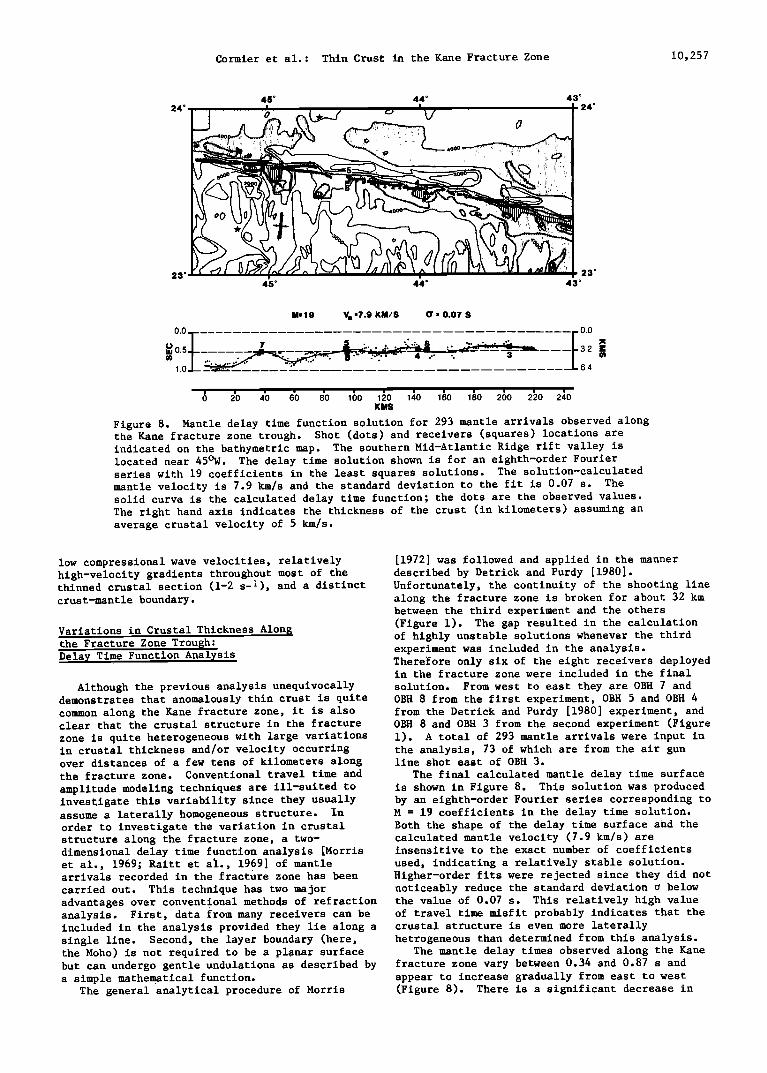
Figure 8. Mantle delay time function solution for 293 mantle arrivals observed along the Kane fracture zone trough. Shot (dots) and receivers (squares) locations are indicated on the bathymetric map. The southern Mid-Atlantic Ridge rift valley is located near 45øW. The delay time solution shown is for an eighth-order Fourier series with 19 coefficients in the least squares solutions. The solution-calculated mantle velocity is 7.9 km/s and the standard deviation to the fit is 0.07 s. The solid curve is the calculated delay time function; the dots are the observed values. The right hand axis indicates the thickness of the crust (in kilometers) assuming an average crustal velocity of 5 km/s.
low compressional wave velocities, relatively high-velocity gradients throughout most of the thinned crustal section (1-2 s -i), and a distinct crust-mantle boundary.
Variations in Crustal Thickness Along the Fracture Zone Trough:
Delay Time Function Analysis
Although the previous analysis unequivocally demonstrates that anomalously thin crust is quite common along the Kane fracture zone, it is also clear that the crustal structure in the fracture zone is quite heterogeneous with large variations in crustal thickness and/or velocity occurring over distances of a few tens of kilometers along the fracture zone. Conventional travel time and amplitude modeling techniques are ill-suited to investigate this variability since they usually assume a laterally homogeneous structure. In order to investigate the variation in crustal structure along the fracture zone, a two- dimensional delay time function analysis [Morris et al., 1969; Raitt et al., 1969] of mantle arrivals recorded in the fracture zone has been
carried out. This technique has two major
[1972] was followed and applied in the manner described by Detrick and Purdy [1980]. Unfortunately, the continuity of the shooting line along the fracture zone is broken for about 32 km between the third experiment and the others (Figure 1). The gap resulted in the calculation of highly unstable solutions whenever the third experiment was included in the analysis. ThereEore only six of the eight receivers deployed in the fracture zone were included in the final solution. From west to east they are OBH 7 and OBH 8 from the first experiment, OBH 5 and OBH 4 from the Detrick and Purdy [1980] experiment, and OBH 8 and OBH 3 from the second experiment (Figure 1). A total of 293 mantle arrivals were input in the analysis, 73 of which are from the air gun line shot east of OBH 3.
The final calculated mantle delay time surface is shown in Figure 8. This solution was produced by an eighth-order Fourier series corresponding to M = 19 coefficients in the delay time solution. Both the shape of the delay time surface and the calculated mantle velocity (7.9 km/s) are insensitive to the exact number of coefficients
used, indicating a relatively stable solution. Higher-order fits were rejected since they did not noticeably reduce the standard deviation o below
advantages over conventional methods of refraction the value of 0.07 s. This relatively high value analysis. First, data from many receivers can be of travel time misfit probably indicates that the included in the analysis provided they lie along a crustal structure is even more laterally single line. Second, the layer boundary (here, hetrogeneous than determined from this analysis. the Moho) is not required to be a planar surface The mantle delay times observed along the Kane but can undergo gentle undulations as described by fracture zone vary between 0.34 and 0.87 s and a simple mathematical function. appear to increase gradually from east to west
The general analytical procedure of Morris (Figure 8). There is a significant decrease in
10,258 Cormier et al.: Thin Crust in the Kane Fracture Zone
1. 4 KM/S 4.5 5
• 4 •
0 I 2 3 4 5 6 7
thin crust found at all the receivers located farther east in the fracture zone valley.
We thus conclude that the large calculated variations in mantle delay time observed along the Kane fracture zone principally reflect variations in the depth to Moho. Changes in apparent crustal thickness of 2-3 km appear to occur commonly over distances of a few tens of kilometers along the fracture zone with the thickest cruat (5-6.5 km) present just east and west of the ridge-transform intersection (see right-hand axis of Figure 8).
The systematic decrease in mantle delay times from west to east along the fracture zone is more difficult to interpret. It may indicate a general
inverse correlation between water depth and delay time; the smallest mantle delay times are associated with the deeper basins within the fracture zone valley (e.g., at OBH's 4 and 8 near 44øW and at 0BH 3). The largest mantle delay times (0.8-0.9 s) are found in the transform valley west of OBH 7.
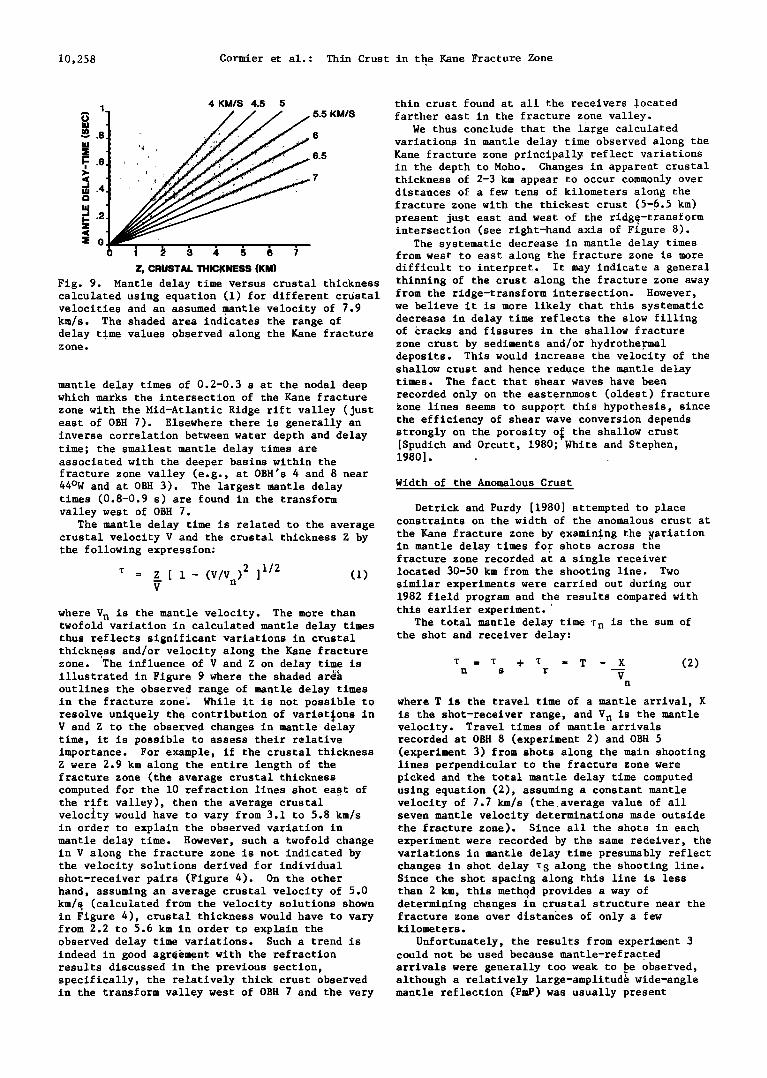
The mantle delay time is related to the average crustal velocity V and the crustal thickness Z by the following expression:
T = • [ 1- (V/Vn)2 ]1/2 (1) V
where V n is the mantle velocity. The more than twofold variation in calculated mantle delay times thus reflects significant variations in crustal thickness and/or velocity along the Kane fracture zone. The influence of V and Z on delay time is illustrated in Figure 9 where the shaded ar• outlines the observed range of mantle delay times
strongly on the porosity o• the shallow crust [Spudich and Orcutt, 1980; White and Stephen, 1980]
Width of the Anomalous Crust
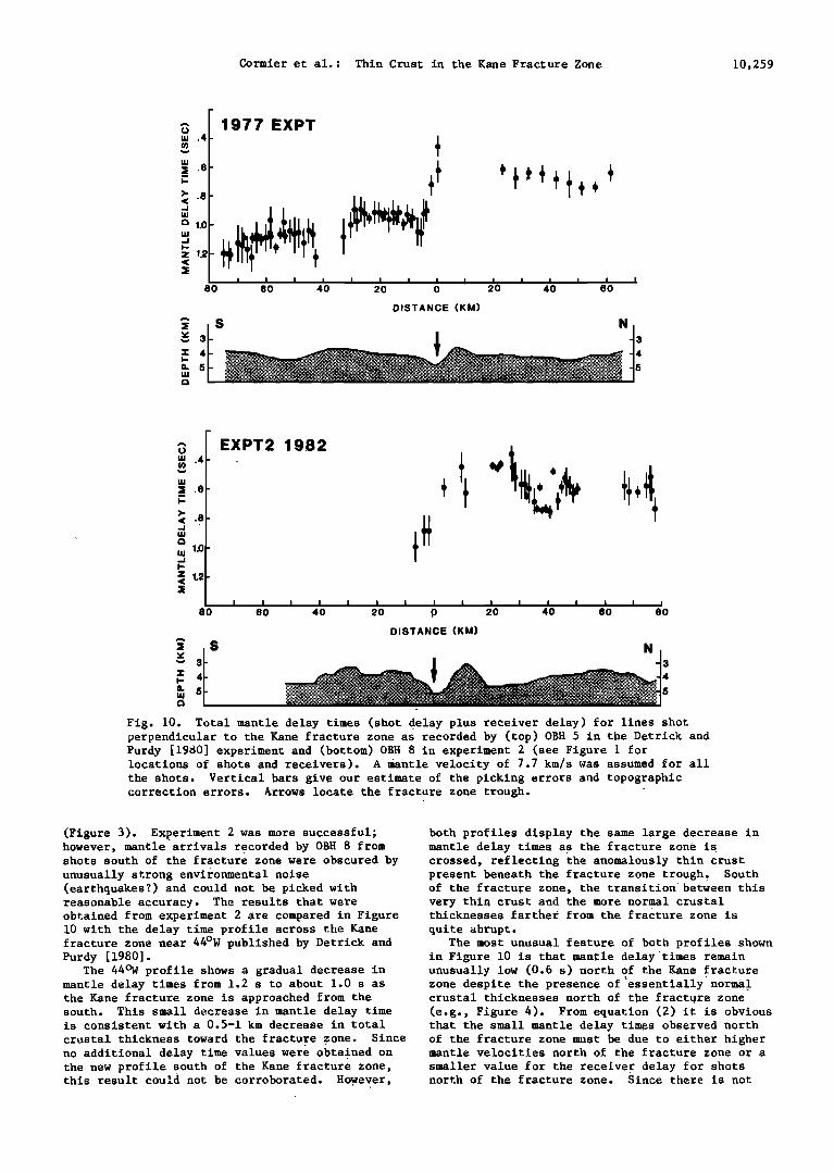
Detrick and Purdy [1980] attempted to place constraints on the width of the anomalous crust at
the Kane fracture zone by examining the •ariation in mantle delay times for shots across the fracture zone recorded at a single receiver located 30-50 km from the shooting line. Two similar experiments were carried out during our 1982 field program and the results compared with
,
this earlier experiment. The total mantle delay time z n is the sum of
the shot and receiver delay:
z = z + T = T - X (2) n s r V
n
in the fracture zone[ While it is not possible to where T is the travel time of a mantle arrival, X resolve uniquely the contribution of variations in is the shot-receiver range, and V n is the mantle V and Z to the observed changes in mantle delay velocity. Travel times of mantle arrivals time, it is possibl e to assess their relative recorded at OBH 8 (experiment 2) and OBH 5 importance. For example, if the crustal thickness (experiment 3) from shots along the main shooting Z were 2.9 km along the entire length of the lines perpendicular to the fracture zone were fracture zone (the average crustal thickness picked and the total mantle delay time computed computed for the l0 refraction lines shot east of using equation (2), assuming a constant mantle the rift valley), then the average crustal velocity of 7.7 km/s (the average value of all velocity would have to vary from 3.1 to 5.8 km/s seven mantle velocity determinations made outside in order to explain the observed variation in the fracture zone). Since all the shots in each mantle delay time. However, such a twofold change experiment were recorded by the same receiver, the in V along the fracture zone is not indicated by variations in mantle delay time presumably reflect the velocity solutions derived for individual changes in shot delay TS along the shooting line. shot-receiver pairs (Figure 4). On the other Since the shot spacing along this line is less hand, assuming an average crustal velocity of 5.0 than 2 km, this methqd provides a way of km/• (calculated from the velocity solutions shown determining changes in crustal structure near the in Figure 4), crustal thickness would have to vary fracture zone over distances of only a few from 2.2 to 5.6 km in order to explain the kilometers. observed delay time variations. Such a trend is Unfortunately, the results from experiment 3 indeed in good agreement with the refraction could not be used because mantle-refracted results discussed in the previous section, arrivals were generally too weak to pe observed, specifically, the relatively thick crust observed although a relatively large-amplitud& wide-angle in the transform valley west of OBH 7 and the very mantle reflection (PmP) was usually present
Z, CRUSTALTHICKNESS (KM)
Fig. 9. Mantle delay time versus crustal thickness thinning of the crust along the fracture zone away calculated using equation (1) for different crustal from the ridge-transform intersection. However, velocities and an assumed .mantle velocity of 7.9 we believe it is more likely that this systematic km/s. The shaded area indicates the range of decrease in delay time reflects the slow filling delay time values observed along the Kane fracture of Cracks and fissures in the shallow fracture zone. zone crust by sediments and/or hydrotheTmal
deposits. This would increase the velocity of the shallow crust and hence reduce the mantle delay
mantle delay times of 0.2-0.3 s at the nodal deep times. The fact that shear waves have been which marks the intersection of the Kane fracture recorded only on the easternmost (oldest) fracture zone with the Mid-Atlantic Ridge rift valley (just Zone lines seems to suppoTt this hypothesis, since east of OBH 7). Elsewhere there is generally an the efficiency of shear wave conversion depends
Cormier et al.: Thin Crust in the Kane Fracture Zone 10,259
1977 EXPT
•' ø8-
"• 1.o •• . i I I i I I I I I I I
80 60 40 20 0 20 4•0 I I I 80
DISTANCE (KM)
N 3
.4-
1.0-
1.2
80
EXPT2 1982
I I I I I I I I I I I I I I I I 60 40 20 0 20 40 60 80
DISTANCE (KM)
• S N • '• 3
Fig. 10. Total mantle delay times (shot_ delay plus receiver de•lay) for lines shot perpendicular to the Kane fracture zone as recorded by (top) OBH 5 in the Detrick and Purdy [1950] experiment and (bottom) OBH 8 in experiment 2 (see Figure 1 for locations of shots and receivers). A mantle velocity of 7.7 km/s was assumed for all the shots. Vertical bars give our estimate of the picking errors and topographic correction errors. Arrows locate the fracture zone trough.
(Figure 3). Experiment 2 was more successful; however, mantle arrivals recorded by OBH 8 from shots south of the fracture zone were obscured by unusually strong environmental noise (earthquakes?) and could not be picked with reasonable accuracy. The results that were obtained from experiment 2 are compared in Figure 10 with the delay time profile across the Kane fracture zone near 44øW published by Detrick and Purdy [1980].
The 44øW profile shows a gradual decrease in mantle delay times from 1.2 s to about 1.0 s as the Kane fracture zone is approached from the south. This small decrease in mantle delay time is consistent with a 0.5-1 km decrease in total
both profiles display the same large decrease in mantle delay times as the fracture zone is crossed, reflecting the anomalously thin crust present beneath the fracture zone trough• South of the fracture zone, the transition between this very thin crust and the more normal crustal thicknesses farther from the fracture zone is
quite abrupt. The most unusual feature of both profiles shown
in Figure 10 is that mantle delayStimes remain unusually low (0.6 s) north of the Kane •racture zone despite the presence of•essentially normal crustal thicknesses north of the fracture zone (e.g., Figure 4). From equation (2) it is obvious that the small mantle delay times observed north
crustal thickness toward the fracture zone. Since of the fracture zone must be due to either higher no additional delay time values were obtained on mantle velocities north of the fracture zone or a the new profile south of the Kane fracture zone, smaller value for the receiver delay for shots this result could not be corroborated. However, north of the fracture zone. Since there is not
10,260 Cormier et al.: Thin Crust in the Kane Fracture Zone
23ø40
23'30
• ' - 0 "/' '; ":':':':':':':':':':':':':': • ._ '" .- ! .•:-:.:':.:-:.;.:.:-::-:-:-:. . ==================================== I ......... "'""'""':"'"'"' '"' '"'" ....
.......... ...... ,.-........ :-. '-: :::::. ,", ':':::i:i:i:i:i::: • •-.. -.:.:.:.:.::' •- ?•:¾"'1;•::•:•!:•i:: •'•'• ..... .. •':: "'"" ::: ": :::::: • ' "-:.'i":::i
- ;:::::;:::::;::::..:::.i::.:::!: :: . , , • \
- ".'.'.'.....'..o ' • ...... '" I l•"'""'-'J•/ > :1,. . l , '"'::i::h" !:!i:.:,.Yl,'/ '
45 ø00 44 ø 50
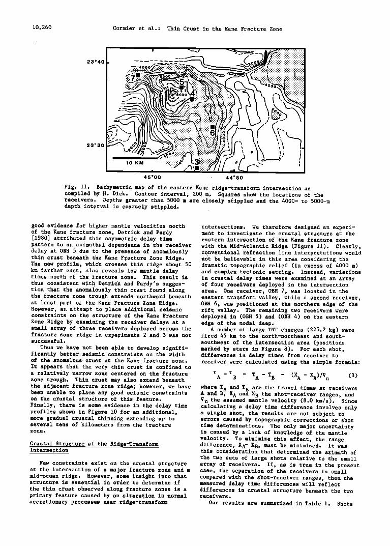
Fig. 11. Bathymetric map of the eastern Kane ridge-transform intersection as compiled by H. Dick. Contour interval, 200 m. Squares show the locations of the receivers. Depths greater than 5000 m are closely stippled and the 4000- to 5000-m depth interval is coarsely stippled.
good evidence for higher mantle velocities north intersections. We therefore designed an experi- of the Kane fracture zone, Detrick and Purdy ment to investigate the crustal structure at the [1980] attributed this asymmetric delay time eastern intersection of the Kane fracture zone pattern to an azimuthal dependence in the receiver with the Mid-Atlantic Ridge (Figure 11). Clearly, delay at OBH 5 due to the presence of anomalously conventional refraction line interpretations would thin crust beneath the Kane FTacture Zone Ridge. n•t be believable in this area considering the The new profile, which crosses this ridge about 50 dramatic topographic relief (in excess of 4000 m) km farther east, also reveals low mantle delay and complex tectonic setting. Instead, variations times north of the fracture zone. This result is in crustal delay times were examined at an array thus consistent with Detrick and PuTdy's sugges- of four receivers deployed in the intersection tion that the anomalously thin crust found along area. One receiver, OBH 7, was located in the the fracture zone trough extends northward beneath eastern transform valley, while a second receiver, at least part of the Kane Fracture Zone Ridge. OBH 6, was positioned at the northern edge of the However, an attempt to place additional seismic rift valley. The remaining two receivers were constraints on the structure of the Kane Fracture deployed in (OBH 5) and (OBH 4) on the eastern Zone Ridge by examining the receiver delays at a edge of the nodal deep. small array of three receivers deployed across the A number of large TNT charges (225.2 kg) were fracture zone ridge in expeTiments 2 and 3 was not fired 45 km to the north-northeast and south- successful. southwest of the intersection area (positions
Thus we have not been able to develop signifi- marked by stars in Figure 8). For each shot, ficantly better seismic constraints on the width differences in delay times from receiver to of the anomalous crust at the Kane fracture zone. receiver were calculated using the simple formula: It appears that the very thin crust is confined to a relatively narrow zone centered on the'fracture • - • = A B T A - T B - (X A - •)/V (3) n zone trough. Thin crust may also extend beneath the adjacent fracture zone ridge; however, we have where T A and T B are the travel times at receivers been unable to place any good seismic constraints A and B, X A and X B the shot-receiver ranges, and on the crustal structure of this feature.
Finally, there is some evidence in the delay time profiles shown in Figure 10 for an additional, more gradual crustal thinning extending up to several tens of kilometers from the fracture zone.
Crustal Structure at the Rid•e.-Transfo. rm Intersection
V n the assumed mantle velocity (8.0 km/s). Since calculating a delay time difference involves only a single shot, the results are not subject to errors caused by topographic corrections or shot time determinations. The only major uncertainty is caused by a lack of knowledge of the mantle velocity. To minimize this effect, the range difference, X A- XB, must be minimized. It was this consideration that determined the azimuth of the two sets of large shots relative to the small
Few constraints exist on the crustal structure array of receivers. If, as is true in the present at the intersection of a major fracture zone and a case, the separation of the receivers is small mid-ocean ridge. However, some insight into that compared with the shot-receiver ranges, then the structure is essential in order tO determine if measured delay time differences will reflect the thin crust observed along fracture zones is a differences in crustal structure beneath the two primary feature caused by an alteration in normal receivers. accretionary processes near ridge-transform Our results are summ-•rized in Table 1. Shots
Cormier et al.: Thin Crust in the Kane Fracture Zone 10,261
TABLE 1. Delay Time Differences and Range Differences for the Different Receiver
Pairs Located in the Eastern Ridge- Transform Intersection Region
T _T A B XA - XB Delay Time Differences Range Differences
(S) (km)
Shot 6-7 5-6 4-6 6-7 5-6 4-6
Shots NNE of the Ridge-Transform Intersection 104 0.07 -0.24 0.01 1.52 1.77 4.46 105 0.05 -0.22 -0.02 1.67 1.68 4.39 106 0.07 -0.23 0.01 1.56 1.76 4.42
Shots SSW of the Ridge-Transform Intersection 201 -0.09 -0.16 0.20 -0.93 -0.23 -2.43 202 -0.10 -0.15 0.21 -0.98 -0.10 -2.38
o• øø o .... o
.•o0
o•Oø• • • OBH •6
.
•11 ,, ,,,,11 Illllllll;lll 'lllllllllll' 0 I0 20 50 40 50
RANGE (kin)
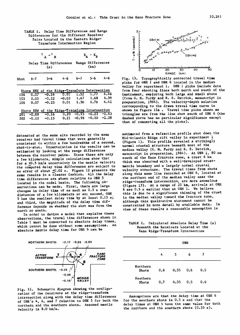
Fig. 13. Topographically corrected travel time picks for OBH 1 and OBH 6 located in the median valley for experiment 1. OBH 1 picks include data from four shooting lines both north and south of the instrument, employing both large and small shots (from G. M. Purdy and R. S. Detrick, manuscript in preparation, 1984). The velocity-depth solution corresponding to the drawn travel time curve is shown in Figure 15a . Travel time picks shown as triangles are from the line shot south of OBH 6 (the dashed curve has no particular significance except that of connecting all the picks).
detonated at the same site recorded by the same estimated from a refraction profile shot down the receiver had travel times that were generally Mid-Atlantic Ridge rift valley in experiment 1 consistent to within a few hundredths of a second, (Figure 1). This profile revealed a strikingly shot-to-shot. Uncertainties in the results can be normal crustal structure beneath most of the estimated by looking at the range differences median valley (G. M. Purdy and R. S. Derrick, between the receiver pairs. Since these are only manuscript in preparation, 1984). At OBH 1, 80 km a few kilometers, simple calculations show that south of the Kane fracture zone, a crust 6 km for a +0.5 km/s uncertainty in the mantle velocity thick was observed with a well-developed crust- the com--puted delay time differences are subject to mantle boundary and a largely normal crustal an error of about +0.02 s. Figure 12 presents the velocity structure. The travel times from shots same results in a clearer fashion. All the delay along this same line recorded at OBH 6, located at time differences are shown relative to OBH 5 located in the nodal basin. The following ob- servations can be made. First, there are large changes in delay time of as much as 0.3 s over distances of a few kilometers or so; second, OBH 5 has the smallest delay time by at least 0.15 s; and third, the magnitude of the delay time dif- ference depends on whether the shot was from the north or south.
In order to devise a model that explains these observations, the travel time differences shown in Table I must be converted to absolute delay times, which cannot be done without some assumptions. An absolute mantle delay time for OBH 6 can be
the northern end of the median valley near the ridge-transform intersection, are more anomalous (Figure 13). At a range of 25 km, arrivals at OBH 6 are 0.5 s earlier than at OBH 1. We believe this is due to a significant thinning of the crust in the median valley toward the fracture zone, although this qualitative statement cannot be constrained in more detail by available data. In view of these results a reasonable assumption is
TABLE 2. Calculated Absolute Delay Time (s) Beneath the Receivers Located at the
Kane Ridge-Transform Intersection
NORTHERN SHOTS: -0.17 -0.23 -0.23 .! , ,.! ,.J
/
ACr, VE 7 / • 4 ,/ KANE , ' 6 ZONE
SOUTHERN SHOTS: -0.25 , I I -0.36
,• • MEDIAN
-0.15' • VALLEY
OBH
4 5 6 7
Northern
Shots 0.6 0.35 0.6 0.5
Southern
Shots 0.7 0.35 0.5 0.6
Fig. 12. Schematic diagram showing the configu- ration of the receivers at the ridge-transform intersection along with the delay time differences Assumptions are that the delay time at OBH 6 of OBH's 4, 6, and 7 relative to OBH 5 for both the for the southern shots is 0.5 s and that the northern and the southern shots. Assumed mantle delay times at OBH b have the same value for both velocity is 8.0 km/s. the northern and the southern shots (0.35 s).
10,262 Cormier et al.: Thin Crust in the Kane Fracture Zone
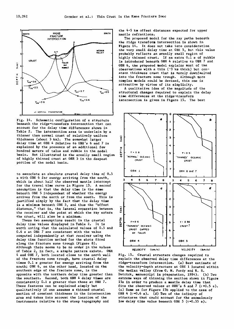
T?s -0.6 9 'TSN' 0 6
x4 VERTICAL EXAGGERATION J" I0 kin "I io
Fig. 14. Schematic configuration of a structure beneath the ridge-transform intersection that can account for the delay time differences shown in Table 2. The intersection area is underlain by a thinner than normal crust of relatively uniform thickness (about 3 km). The somewhat larger delay time at OBH 4 relative to OBH's 6 and 7 is explained by the presence of an additional few hundred meters of talus and rubble in the nodal
basin. Not illustrated is the areally small region of highly thinned crust at OBH 5 in the deepest portion of the nodal basin.
to associate an absolute crustal delay time of 0.5 s with OBH 6 for energy arriving from the south, which is about half the observed mantle intercept for the travel time curve in Figure 13. A second assumption is that the delay time is the same beneath OBH 5 independent of whether the energy arrives from the north or from the south. This is
justified simply by the fact that the delay time is a minimum beneath OBH 5, and thus the "offset distance," that is, the lateral separation between the receiver and the point at which the ray enters the crust, will also be a minimum.
These two assumptions result in the crustal delay time values displayed in Table 2. It is worth noting that the calculated values of 0.5 and 0.6 s at OBH 7 are consistent with the value
computed independently at that receiver using the delay time function method for the shots fired along the fracture zone trough (Figure 8). Although there seems to be no order in the values of Table 2, in fact, a simple pattern exists. OBH 4 and OBH 7, both located close to the north wall of the fracture zone trough, have crustal delay times 0.1 s greater for energy arriving from the south; OBH 6, on the other hand, located on the southern edge of the fracture zone, is the
the 4-5 km offset distances expected for upper mantle refractions.
The proposed model for the ray paths beneath the ridge transform intersection is shown in Figure 14. It does not take into consideration the very small delay time at OBH 5, but this value probably reflects an areally small region of highly thinned crust. If an extra 0.1 s of rubble is introduced beneath OBH 4 relative to OBH 7 and
OBH 6, the proposed model explains most of the observations with a thin (~3 km thick) but con- stant thickness crust that is merely downfaulted into the fracture zone trough. Although more complex models could be devised, this one is attractive by virtue of its simplicity.
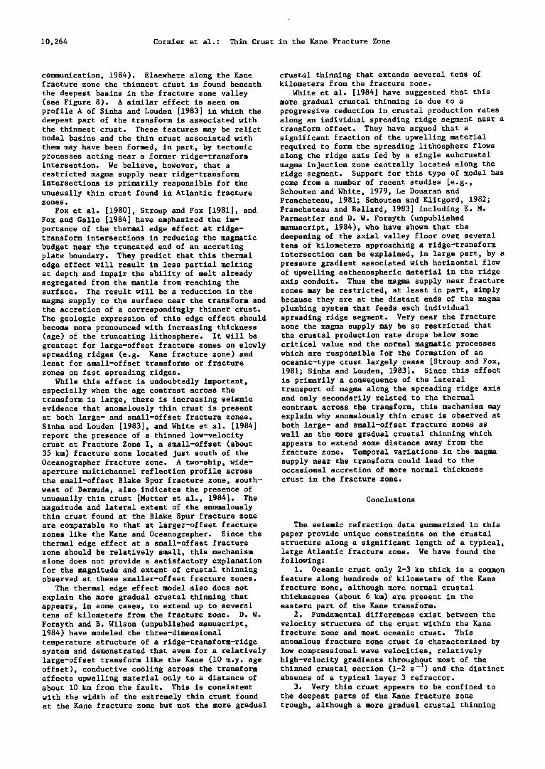
A qualitative idea of the magnitude of the structural changes required to explain the delay time differences at the ridge-transform intersection is given in Figure 15. The best
i i i i
.
'NORMAL' OCEANIC CRUST •,,
- OBH !
i I I
3 4 5 6 7 8
! -
' THINNED ' OCEANIC
CRUST CAPPED
BY TALUS
OBH 4
I I I t I
VELOCITY (km/s)
T=05
'THINNED' OCEANIC CRUST
OBH 6 ond 7
I I I
3 4 5 6 7 8
CRUST ? --
OBH 5
i i I I I
VELOCITY (km/s)
Fig. 15. Crustal structure changes required to explain the observed delay time differences at the ridge-transform intersection. (a) Best estimate of the velocity-depth structure at OBH 1 located within the median valley (from G. M. Purdy and R. S.
opposite with the northern delay time greater than Detrick, manuscript in preparation, 1984). (b) Two the southern. Second, both OBH 4 delay times are extreme ways of thinning the section shown in Figure consistently 0.1 s greater than those at OBH 7. 15a in order to produce a mantle delay time that These features can be explained simply but fits the observed values at OBH's 6 and 7 (T=0.5 s). qualitatively if one assumes a thinned crustal (c) Same as for Figure 15b applied to the case of section of constant thickness in the intersection OBH 4 •=0.6 s). (d) Two of the infinity of area and takes into account the location of the structures that could account for the anomalously instruments relative to the steep topography and low delay time value beneath OBH 5 (z=0.35 s).
Cormier et al.: Thin Crust in the Kane Fracture Zone 10,263
estimate of the velocity structure beneath OBH i transform valley, although apparent crustal in the median valley about 80 km south of the Kane thicknesses of 4.5-5.0 km were found elsewhere fracture zone is shown in Figure 15a. It has a along the fracture zone. Apparent crustal total crustal thickness of about 6 km and a thicknesses of about 5 km (albeit with lower crustal velocity structure typical of normal crustal velocities) have also been reported for oceanic crust except for somewhat low velocities the Vema transform valley [Ludwig and Rabinowitz, in the upper part of layer 3. This section can be 1980; Detrick et al., 1982]. Thus the large thinned to fit the observations at OBH 6 and OBH 7 Atlantic fracture zones appear to be characterized (Figure 15b): 0.3 s can be subtracted from the delay times either by removing high-velocity material from the lowermost part of the crust or correspondingly less low-velocity material from the uppermost part of the crust. The section beneath OBH 4 (Figure 15c) is interpreted to be essentially the same except for an additional few hundred meters of low-velocity material on top to explain the extra 0.1 s delay time. OBH 5 situated in the nodal deep and with a delay time of only 0.35 s is the major anomaly. Shown in Figure 15d are just two of the many models one could think up to satisfy the data. One extreme has only a kilometer of crust.
Aii of these results can be summarized as
follows. A crustal structure very close to that
by both anomalously thin crust and large apparent variations in total crustal thickness. Since
fracture zones are found every 50-100 km along the Mid-Atlantic Ridge, they clearly represent a major source of seismic crustal heterogeneity in the North Atlantic.
The high seismic velocities observed at shallow depths beneath the Kane and other North Atlantic fracture zones almost certainly indicate the presence of unaltered, upper mantle peridotite. The lower velocities observed above the seismic
Moho may represent highly fractured basaltic or gabbroic basement rocks [Fox et al., 1976; Detrick et al., 1982], partially serpentinized ultramafics [Fox et al., 1976; Detrick et al., 1982; Sinha and Louden, 1983], or locally thick sections of rock
typically observed in the ocean basins exists over taius, rubble, and sediment [OTTER Scientific Team a significant portion of the median valley south of the Kane fracture zone (G. M. Purdy and R. S. Detrick, manuscript in preparation, 1984). Near the fracture zone the crust in the median valley appears to thin, although travel times do not really constrain the distance over which this thinning takes place. The ridge-transform intersection is underlain by thinner than normal crust of relatively uniform thickness except beneath the nodal basin where the crust is extremely thin (perhaps less than i km thick).
Discussion
The results from this study establish without question that unusually thin crust is a common feature along a significant length of the Kane fracture zone. With upper mantle velocities (7.7-8.1 km/s) present at depths of only 2-3 km below the seafloor the Kane fracture zone is
associated with the thinnest crust found anywhere on earth. The seismic structure of this anomalous fracture zone crust also bears little resemblance
to that of most oceanic crust. It is typically characterized by low compressional wave velocities, relatively high-velocity gradients (1-2 s -1) throughout most of the thinned crustal section and the distinct absence of a typical layer 3 refractor. The width of the zone of significant crustal thinning at the Kane fracture
1984 a, b]. As a result, the geological significance of the Moho may change laterally along the fracture zone (P. J. Fox and D. G. Gallo, manuscript in preparation, 1984). In some cases, Moho will mark the transition from gabbroic rocks to the cumulate uitramafics and tectonized
harzburgites of the upper mantle. Elsewhere, the mafic crust may be exceptionally thin, and Moho may mark the depth of hydration (serpentinization) of the upper mantle beneath a thin, highly fractured crustal section. The large apparent variations in depth to Moho observed along the Kane and Oceanographer fracture zones thus may reflect either a change in the thickness of the mafic crust and its constituent basaltic and
gabbroic layers or differences in the depth and extent of serpentinization of the uitramafics lying beneath a very thin mafic crust.
Origin of Anomalous Fracture Zone Crust
The presence of unusually thin crust along hundreds of kilometers of the Kane fracture zone trough, including parts of the fracture zone not bordered by the Kane Fracture Zone Ridge, make it unlikely that this anomalous crust is caused by the emplacement of a large ultramafic intrusion along the fracture zone or other regional tectonic effects such as extension and crustal necking due to changing plate motions. The presence of un-
zone is not well constrained, but it appears to be usually thin crust within the Mid-Atlantic Ridge confined to a relatively narrow zone about 10-15 km wide centered in the fracture zone valley, although an additional, more gradual crustal thinning may extend up to several tens of kilometers from the fracture zone.
Morphologically and tectonically, the Kane fracture zone is typical of other large, slowly
rift valley at the ridge-transform intersection strongly suggests that this anomalous crust is a primary feature which reflects a modification of normal accretionary processes near ridge-transform intersections. However, there is some seismic evidence that tectonic processes may be important, at least locally, in the formation of the un-
slipping transforms in the North Atlantic, and it usually thin crust found in fracture zones. At is likely that the severe crustal thinning the Kane fracture zone, for example, the thinnest associated with the Kane is also present along at crust (perhaps less •han i km thick) is found least parts of other large Atlantic fracture beneath the nodal basin at the ridge-transform zones. Refraction data from the Oceanographer intersection. There is some morphologic evidence fracture zone [Sinha and Louden, 1983; E. L. Ambos that these nodal deeps are small pull-apart basins et al., manuscript in preparation, 1984] indicate in which an initially thin crust may be tectoni- the presence of extremely thin crust beneath the cally thinned even further (D. Gallo, personal
10,264 Cormier et al.: Thin Crust in the Krone Fracture Zone
communication, 1984). Elsewhere along the Kane fracture zone the thinnest crust is found beneath
the deepest basins in the fracture zone valley (see Figure 8). A similar effect is seen on profile A of Sinha and Louden [1983] in which the deepest part of the transform is associated with the thinnest crust. These features may be relict nodal basins and the thin crust associated with
them may have been formed, in part, by tectonic processes acting near a former ridge-transform intersection. We believe, however, that a restricted magma supply near ridge-transform intersections is primarily responsible for the unusually thin crust found in Atlantic fracture zones,
Fox et al. [1980], Stroup and Fox [1981], and Fox and Gallo [1984] have emphasized the im- portance of the thermal edge effect at ridge- transform intersections in reducing the magmatic budget near the truncated end of an accreting plate boundary. They predict that this thermal edge effect will result in less partial melting at depth and impair the ability of melt already segregated from the mantle from reaching the surface. The result will be a reduction in the
crustal thinning that extends several tens of kilometers from the fracture zone.
White et al. [1984] have suggested that this more gradual crustal thinning is due to a progressive reduction in crustal production rates along an individual spreading ridge segment near a transform offset. They have argued that a significant fraction of the upwelling material required to form the spreading lithosphere flows along the ridge axis fed by a single subcrustal magma injection zone centrally located along the ridge segment. Support for this type of model has come from a number of recent studies [e.g., Schouten and White, 1979, Le Douaran and Francheteau, 1981; Schouten and Klitgord, 1982; Francheteau and Ballard, 1983] including E. M. Parmentier and D. W. Forsyth (unpublished manuscript, 1984), who have shown that the deepening of the axial valley floor ove= several tens of kilometers approaching a ridge-transform intersection can be explained, in large part, by a pressure gradient associated with horizontal flow of upwelling asthenospheric material in the ridge axis conduit. Thus the magma supply near fracture zones may be restricted, at least in part, simply
magma supply to the surface near the transform and because they are at the distant ends of the magma the accretion of a correspondingly thinner crust. plumbing system that feeds each individual The geologic expression of this edge effect should spreading ridge segment. Very near the fracture become more pronounced with increasing thickness zone the magma supply may be so restricted that (age) of the truncating lithosphere. It will be the crustal production rate drops below s øme greatest for large-offset fracture zones on slowly critical value and the normal magmatic processes spreading ridges (e.g. Kane fracture zone) and which are responsible for the formation of an least for small-offset transforms or fracture zones on fast spreading ridges.
While this effect is undoubtedly important, especially when the age contrast across the transform is large, there is increasing seismic evidence that anomalously thin crust is present at both large- and small-offse t fracture zones. Sinha and Louden [1983], and White et•al. [1984] report the presence of a thinned low-Velocity crust at Fracture Zone I, a small-Offset (about 35 km) fracture zone located just soUth of the Oceanographer fracture zone. A two-ship, wide- aperture multichannel reflection profile across the small-offset Blake Spur fracture zone, south- west of Bermuda, also indicates the presence of unusually thin crust [Mutter et al., 1984]. The magnitude and lateral extent of the anomalously thin crust found at the Blake Spur fracture zone are comparable to that at larger-offset fracture zones like the Kane and Oceanographer. Since the thermal edge effect at a small-offset fracture zone should be relatively small, this mechanism alone does not provide a satisfactory explanation for the magnitude and extent of crustal thinning observed at these smaller-offset fracture zones.
The thermal edge effect model also does not explain the more gradual crustal thinning that appears, in some cases, to extend up to several tens of kilometers from the fracture zone. D.W.
Forsyth and B. Wilson (unpublished manuscript, 1984) have modeled the three-dimensional temperature structure of a ridge-transform-ridge
oceanic-type crust largely cease [Stroup and Fox, 1981; Sinha and Louden, 1983]. Since this effect is primarily a consequence of the lateral transport of magma along the spreading ridge axis and only secondarily related to the thermal contrast across the transform, this mechanism may explai n why anomalously thin crust is observed at both large- and small-offset fracture zones as well as the more gradual crustal thinning which appears to extend some distance away from the fracture zone. Temporal variations in the magma supply near the transform could lead to the occasional accretion of more normal thickness crust in the fracture zone.
Conclusions
The seismic refraction data summarized in this
paper provide unique constraints on the crustal structure along a significant length of a typical, large Atlantic fracture zone. We have found the following:
1. Oceanic crust only 2-3 km thick is a common feature along hundreds of kilometers of the Kane fracture zone, although more normal crustal thicknesses (about 6 km) are present in the eastern part of the Kane transform.
2. Fundamental differences exist between the
velocity structure of the crust within the Kane fracture zone and most oceanic crust. This
anomalous fracture zone crust is characterized by system and demonstrated that even for a relatively low compressional wave velocities, relatively large-offset transform like the Kane (10 m.y. age high-velocity gradients throughout most of the offset), conductive cooling across the transform thinned crustal section (1-2 s-l) and the distinct affects upwelling material only to a distance of absence of a typical layer 3 refractor. about 10 km from the fault. This is consistent 3. Very thin crust appears to be confined to with the width of the extremely•thin crust found the deepest parts of the Kane fracture zone at the Kane fracture zone but not the more gradual trough, although a more gradual crustal thinning
Cormier et al.: Thin Crust in the Kane Fractu.re Zone 10,,265
may extend up to several tens of kilometers from seismic refraction studies, J. Geophys. Res., the fracture zone. 85, 3759-3778, 1980.
4. Exceptionally thin crust is present beneath Detrick, R. S., M. H. Cormier, R. A. Prince, D. the nodal basin at the intersection of the Kane
fracture zone with the Mid-Atlantic Ridge, and this anomalous crust appears to extend at least part way down the Mid-Atlantic Ridge rift valley. Thin crust may also extend beneath at least part of the Kane Fracture Zone Ridge.
We interpret this anomalous fracture zone crust as a thin, intensely fractured and hydrothermally altered basaltic and gabbroic section overlying ultramafics that in places may be extensively • serpentinized. The presence of this unusually thin crust along hundreds of kilometers of the Kane fracture zone, especially at the ridge- transform intersection within the Mid-Atlantic Ridge rift valley, strongly suggests that this
W. Forsyth, and E. L. Ambos, Seismic constraints on the crustal structure within the
Vema Fracture Zone, J. Geo?h•s. Res., 87, 599-610,1982.
Dorman, L. M., and R. S. Jacobson, Linear inversion of body wave data, I, Velocity structure from travel times and ranges, Geo?h•sics, 46, 138-151, 1981.
Diebold, J., and P. Stoffa, The travel-time equation, tau-p mapping and inversion of common midpoint data, Geophysics, 46, 238-254, 1981.
Ewing, J."I., Elementary theory of seismic refraction and reflection measurements, in The Sea, vol. 3, edited by M. N. Hill pp. 1-19, WileyTInterscience, New York, 1963.
anomalous crust is a primary accretionary feature. Ewing , J. I., and G. M. Purdy, Upp.er crustal We believe that this unusually thin crust forms as a result of a restricted magma supply near ridge- transform intersections caused, in part• by the thermal effec t of juxtaposing a cold thick edge of lithosphere against the accreting plate boundary and, in part, because transforms are typically at the'distant ends of the magma system feeding each individual spreading ridge segment. Locally, tectonic prodesses may also be important in
structure in the ROSE area of the East Pacific Rise, J. Geo?h¾. s. Re•., 87, 8397-8402, 1982.
Fox, P. J., The geology of some Atlantic fracture zones, Carribean escarpment and the nature of the oceanic basement and crust, Doctoral, Columbia Univ., New York, 1972•
Fox, P. J., The effect of transform faults on the character of the oceanic crust, Geol. Soc. Am• Abst•.. Programs, •, 403, 1978. •'
producing the very •thin crust found along parts of Fox, P. J., and D. G. Gallo, A tectonic mpdel many large Atlantic fracture zones.
Acknowledgments. This research was sponsored by the National Science Foundation under grant 0CE8025206 to the Woods Hole Oceanographic Institution and the University of Rhode Island. We thank the officers, crew, and scientific complement of the R/V Knorr during cruise KN92-1 when these data were coliect•d. The flawless performance of the ocean bottom hydrophones was due to the technical skill and dedication of D. Koelsch and C. Grant. M.D. Allison, L. Gove, N. Adams, and P. Belknap provided invaluable assistance with various aspects of data reduction and interpretation. We thank C. Sherman for typing the manuscript. Woods Hole Oceanographic Institution contribution 5747.
References
ARCYANA, Transform fault and rift valley from bathyscaph and diving saucer, Science, 190, 108•116, 1975.
Bonatti, E., Serpentinite protusions in the oceanic crust, Earth.Planet. Sci. Lett., 32, 107-113, 1976.
Bonatti, E., Vertical tectonism in oceanic fracture zones, Earth Planet. Sci. Lett., 37, 369v379, 1978.
CAYTROUGH, Geological and geophysical investi- gation of the Mid-Cayman Rise Spreading Center: Initial results and observations, in Deep Drilling Results in the Atlantic Ocean: Oceanic Crust• Maurice Ewin• Ser., vol. 2, edited by'M. Talwani, C. G. Harrison, D. E.
for ridge-transform-ridge plate boundary: Implications for•the strdcture of oceanic lithosphere , Tectonoph.•sics , 104, 205-242, 1984.
Fox, P. J., W. C. Pitman III, and F. Shephard, Crustal plates in the central Atlantic; Evidences for at least two Poles of rotation, Science, 165, 487-489, 1969.
Fox, P.•J., E. Schreiber, H. Rowlett, and K. McCamy, The geology of the Ocea•ographer fracture zone: A model for fracture zones, J. Geoph¾s. Res.., 81, 4117-4128, 1976.
Fox, P. J., R. S. Detrick and G. M. Purdy, Evidence for crustal thinning near fracture zones: Implications for Ophiolites, in Proceedings of the International Ophiolite Sym?osium, edited by A. Panayiotou, pP. 161-168, Cyprus Geological Survey Department, Nicosia, 1980.
Francheteau, J., and R. D. Ballard, The EaSt Pacific Rise near 21øN, 13øN and 20øS: Inferences for along strike variability of axial processes of the mid-ocean ridge, Earth Planet. Sci. Lett., 64, 93-1!6, 1983.
Francheteau, J., P.øChoukrou•e, R. Hekinian, •. LePichon, and D. Needham, Oceanic fracture zones do not provide deep section in the crust, Can. J. Earth Sci., 13, 1223-1235, 1976.
Kar•on, J. A., and H. J. B. Dick, Tectonics of ridge-transform intersections at the Kane . fracture zone, Mar. Geoph•s • Res.• 6, 51-98, 1983.
Kennett, B. L. N., and J. A- Orcutt, A comparison of travel time inversions: Marine refraction
profiles, J. Ge0ph•s•.Res., 81, 4061-4070, 1976.
Hayes, pp. 66-95, AGU, Washington, D.C., 1979. Koelsch, D. E., and G. M. Purdy, An ocean bottom Chapman, C. H., A new method for computing hydrophone instrument for seismic refraction
synthetic seismograms, Geo?h•s, J. R. Astron. experiments in the deep ocean, Mar. Geoph¾s. Soc., 54, 481-518, 1978. Res., 4, 115-125, 1979.
Detrick, R, S., and G. M. Purdy, The crustal Le Douaran, S., and J. Francheteau, Axial depth structure of the Kane fracture zone from anomalies from 10øN to 50øN along the
10,266 Cormier et al.: Thin Crust in the Kane Fracture Zone
Mid-Atlantic Ridge: Correlation with other mantle properties, Earth Planet. Sci. Lett.,
_i4, Louden, K. E., and D. W. Forsyth, Crustal
structure and isostatic compensation near the Kane fracture zone from topography and gravity measurements, I, Spectral analysis approach, Geophys. J. R. Astron. Soc., 68, 725-750, 1982.
Ludwig, W. J. and P. Rabinowitz, Structure of the Vema fracture zone, Mar. Geol., 35, 99-110, 1980.
Miyashiro, A., F. Shido, and M. Ewing, Composition and origin of serpentinites from the Mid-Atlantic Ridge near 24øN and 30øN latitude, Contrib. Mineral. Petrol, 23, 117-127, 1969.
Miyashiro, A., F. Shido, and M. Ewing, Metamor- phism in the Mid-Atlantic Ridge near 24 N and 30 N, Philos. Trans. R. Soc. London Ser. A, 268, 589-603, 1971.
Morris, G. B., R. W. Raitt, and G. G. Shor, Jr., Velocity anisotropy and delay time maps of the mantle near Hawaii, J. Geophys. Res., 74, 4300-4315, 1969.
Morris, G. B., Delay-time function method and its application to the Lake Superior refraction data, J. Geophys. Res., 77, 297-314, 1972.
Mutter, J., R. Detrick, and NAT Study Group, Multi-channel seismic evidence for anomalously thin crust at the Blake-Spur fracture zone, Geology, in press, 1984.
OTTER Scientific Team, The geology of the Oceanographer transform: The ridge-transform intersection, Mar. Geoph•s. Res., •, 109-142, 1984a.
OTTER Scientific Team, The geology of the Oceanographer transform: The transform domain, Mar. Geoph•s. Res., in press, 1984b.
Purdy, G. M., The correction for the travel-time effects of seafloor topography in the interpretation of marine seismic data, J. Geophys. Res., 87, 8389-8396, 1982.
Purdy, G.M., P.D. Rabinowitz, and J. J. A. Velterop, The Kane fracture zone in the central Atlantic Ocean, Earth Planet. Sci. Lett., 45, 429-434, 1979.
Rabinowitz, P. D., and G. M. Purdy, The Kane fracture zone in the western central Atlantic
Ocean, Earth Planet. Sci. Lett., 33, 21-26, 1976.
Raitt, R. W., G. G. Shor, Jr., T. J. G. Francis, and G. B. Morris, Anisotropy of the Pacific
upper mantle, J. Geophys. Res., 74, 3095-3109, 1969.
Schouten, H., and K. D. Klitgord, The memory of the accreting plate boundary and the continuity of fracture zones, Earth Planet. Sci. Lett.,
59, 255-266, 1982. Schouten, H., and R. S. White, Zero-offset
fracture zones, Geology, •, 175-179, 1980. Schouten, H., G. M. Purdy, and P. R. Rabinowitz,
History of the Kane fracture zone, Eos Trans. AGU, 60, 394, 1979.
Sinha• M.C., and K. E. Louden, The Oceanographer fracture zone, I, Crustal structure from Seis- mic refraction studies, Geophys. J. R. Astron. Soc., 75, 713-736, 1983.
Spudich, P. and J. Orcutt, Petrology and porosity of an oceanic crustal site: Results from wave
form modeling of seismic refraction data, J. Geophys. Res., 85, 1409-1433, 1980.
Stroup, J. B., and P. J. Fox, Geologic investi- gations in the Cayman Trough: Evidence for thin crust along the Mid-Cayman Rise, J. Geol., 89, 395-420, 1981.
White, R. S., Atlantic oceanic crust: Seismic structure of a slow spreading ridge, in Ophiolites and Oceanic Lithosphere, Spec. Publ. Geol. Soc. London, 101-111, 1984.
White, R. S., and D. H. Matthews, Variations in oceanic upper crustal structure in a small area of the northeastern Atlantic, Geophys. J. R. Astron. Soc., 42, 189-215, 1980.
White, R. S., and R. A. Stephen, Compressional to shear wave conversion in oceanic crust, Geophys. J. R. Astron. Soc., 63, 547-565, 1980.
White, R. S., R. S. Detrick, M. C. Sinha, and M. H. Cormier, Anomalous seismic crustal structure of oceanic fracture zones, Geophys. J. R. Astron. Soc, in press, 1984.
M.-H. Cormier and R. S. Detrick, Graduate School of Oceanography, University of Rhode Island, Narragansett Bay Campus, Narragansett, RI 02882.
G. M. Purdy, Department of Geology and Geo- physics, Woods Hole Oceanographic Institution, Woods Hole, MA 02543.
(Received March 5, 1984; revised July 16, 1984;
accepted July 18, 1984.)
Related Documents


