AUGUST 1956 In This Issue: REFERENCE PLANE OXIC E COATED CATHODE MICRO -MINIATURE CERAMIC TUBE The Morine Electronics Business Troubleshooting the Yoke and CRT Oscilloscope Probes ANODE GRID GRID RING SUPPORT CYLINDER CATHODE RING HEATER BUTTONS Photo explanation on page 1 !A Modern Cathode Ray Tube Checker Complete Mfrs. Schematics Color Detectors www.americanradiohistory.com

Welcome message from author
This document is posted to help you gain knowledge. Please leave a comment to let me know what you think about it! Share it to your friends and learn new things together.
Transcript
AUGUST 1956
In This Issue:
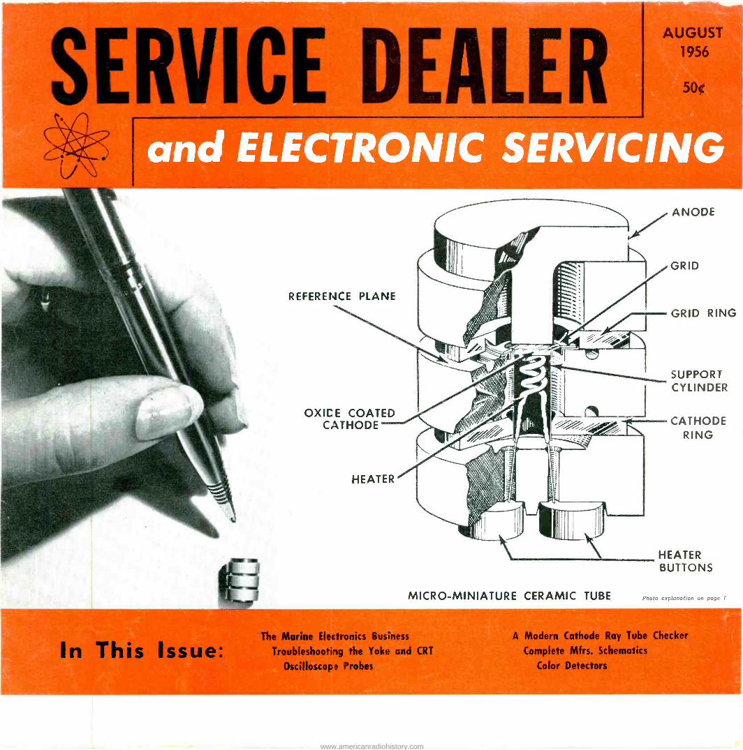
REFERENCE PLANE
OXIC E COATED CATHODE
MICRO -MINIATURE CERAMIC TUBE
The Morine Electronics Business
Troubleshooting the Yoke and CRT
Oscilloscope Probes
ANODE
GRID
GRID RING
SUPPORT CYLINDER
CATHODE RING
HEATER BUTTONS
Photo explanation on page 1
!A Modern Cathode Ray Tube Checker
Complete Mfrs. Schematics
Color Detectors
www.americanradiohistory.com

"A TV network
can't afford
to take chances on tube quality"
As Garry Moore tells over five million
women on the CBS Television Network...
"CBS tubes are made by the tube manufacturing division of
Columbia Broadcasting System. So we know how dependable
they are. That's why we use them here in our own cameras
and other equipment."
Garry also points out that CBS tubes have the Good House-
keeping Guaranty Seal. That means a lot to women ... and
women are your customers.
In fact, if you're like most service technicians, more and
more women are asking you for CBS tubes. Because Garry Moore has convinced them that there are no better tubes made. Yes, you'll ti -1d it's easy to buill customer satisfaction when you use and recommend the tubes you can always de-
pend upon ... CBS tubes.
Garry Moore sells you and your expert service, ho. Have you seen him?
.9 Guaranteed `\. Good Rousekee? nF)
AS,,.,., ,o% CBS-I-IVTRON, Danvers, Massachusetts
A Division of Columbia Broadcasting System, Inc.
EDITORIAL STAFF
Sanford R. Cowan Publisher
Samuel L. Marshall Editor
Oscar Fisch Assistant Editor
Charles W. Gardner, Jr. Editorial Production Manager
San D'Arcy Contributing Editor
Robert T. Dargan Contributing Editor
Paul Goldberg Contributing Editor
Elbert Robberson Marine Communications Editor
Lawrence Fielding Hi-Fi & PA Editor
BUSINESS STAFF Advertising Sales
New York and East
Chicago and
Midwest
West Coast
Richard A. Cowan Jack N. Schneider
67 West 44th Street
New York 36, N. Y.
MUrray Hill 7-2080
Jim Summers
400 North Michigan Ave.
Chicago 11, Illinois SUperior 7-1641
Ted E. Schell 2700 West 3rd Street Los Angeles 57, Calif. DUnkirk 2-4889
David Saltman Advertising Production
CIRCULATION
Harold Weisner _ Circulation Manager
Carol J. Biederman Ass't Circulation Mgr.
Mady Weinbaum Circulation Processing
SERVICE DEALER and ELECTRONIC SERVICING (formerly Radio-TV Service Dealer) is published monthly by Cowan Publishing Corp., 67 West 44th Street, New York 36, New York, MUrray Hill 7-2080. Subscription Price: $3.00 one year, $5.00 two years in the United States, U.S. Pos- sessions, Canada and Mexico. Elsewhere $1.00 per year addi- tional. Single copies 50c. Second Class Mail privileges author- ized at New York, N. Y.
POSTMASTER: SEND FORM 3579 TO SERVICE DEALER anO ELEC-
TRONIC SERVICING, 67 WEST 44th STREET, NEW YORK 36, N. Y
www.americanradiohistory.com

VOL.
SERVICE DEALER and ELECTR
Member
CPA
FEATURE ARTICLES
AUGUST, 1956
The Marine Electronics Business, Part 3, by Elbert Robberson 4 Boat electrical systems described.
Trouble -Shooting the Yoke and CRT, Part 2, by B. Jarmalow 10 Discussion of Yoke construction, operation and trouble shooting; also CRT troubles.
Oscilloscope Probes, by Robert G. Middleton 14 How to use the scope demodulator probe for various circuit tests.
A Modern Cathode Ray Tube Checker, by J. Frank Brumbaugh 20 Description of a CRT checker with unusual features.
Color Detectors, by Bob Dorgan and Sam Marshall 28 Discussion of the various types of detector circuits employed in color TV receivers.
CIRCUIT AND SERVICE FORUM
Service Dealer Complete Manufacturer's Schematics Westinghouse Ch. V2340, V2350, V2342, V2352, V2343, V2341, V2351 23
G.E. "S" line 25
Workbench CBS Color Chassis 205 Motorola Color Chassis BP -902A-01
34 35
Video Speed Servicing Systems Motorola Chassis TS -3268. 37 Silvertone Chassis 128-16
The Answerman Connecting a VU meter to a tape recorder 41
Travler 46A3-burnt out contrast control 41
Hum in TV receivers (not caused by open filters) 43
Reducing strong TV signals 44
DEPARTMENTS
S. R. Cowan Ad Libs 2 New Antennas Rider Speaks . 12 Trade Flashes
Guest Editoria! 18 Association News New Semi -Conductors 22 Buyer's Directory
Advertiser's Index 49
THIS MONTH'S FRONT COVER The new G.E. "micro -miniature" ceramic triode 6BY4 for UHF TV sets.
Entire Contents Copyright 1956, Cowan Publishing Corp.
39
27 32 36 45
COWAN PUELISHING CORP., 61 West 44th Street, New York 36, N. Y.
SERVICE DEALER and ELECTRONIC SERVICING AUGUST, 1956
TWIN LEAD HANKS
.. siaurs.
a4vMMUl%ANfENNA WIRE <malt. 44 Gea./4-f(C 1 OtPr.nIfAr
PtrrerM Ay4L
WiIN LUGS OM
make your
Selling job
EASIER! . S
in addition to 50, 75, 100 ft. put -ups
At your request AMPHENOL now provides new 25 foot hanks in two popular types of Twin Lead. Add these to your AMPHENOL Twin Lead Display Board -and watch your sales and profits increase while your selling job gets easier! Your growing Twin Lead market includes: those who buy a second set (black & white or color) or replace worn-out lead-in or need extra lengths for moving sets.
Don't wait for your customers to ask-stock and display AMPHENOL Hanks in all the popular sizes listed below.
Part No. Description Arrailsble
25 ft. in
50 ft. Manes 75 ft..
et 100 ft.
214-318 Indoor* -60 mill, 7/28 pure copper cond. J J V V
214-056 Standard -60 mil, 7/28 pure copper cond. J J J V
214-559 Steelcore-72 mil, 7/28 copperweld cond. i v Ni V
214-298 Rotator -4 conductor -7/28 pure copper cond. -v V V
214-100 Century -100 mil, 7/28 pure copper cond. 1 'i V V
Now Available in Coils
214-271 Air-Core**-U.S.Pat. 2543696 7/28 pure copper cond. I
*Indoor is the newest AMPHENOL Twin Lead. It's made of pure virgin natural poly- ethylene to harmonize with any interior.
**Now famous AMPHENOL Air -Core is available in pre-cut coil::. Remember: for finest: quality, virgin polyethylene is used in all AMPHENOL Twin Leads.
AMPHENOL ELECTRONICS CORPORATION
chicago 50, illinois
www.americanradiohistory.com
S. R. COWAN
Aá Ills
The Votes Are In
You will recall that in April we announced that starting in May this maga- zine would go to "King - Size" and we explained in a
superficial manner why that change would take place. Now, because so many sub- scribers have asked us to do so, we will give you fuller details as to the reasons for the change.
During the last quarter of 1955 we made a survey and asked every tenth reader of our magazine, (nearly 7,000 of the 70,000), a series of questions. For example, we asked the nation's service- men what they liked about our magazine and other servicemen's maga- zines, what they disliked about our magazine and the other servicemen's maga- zines, and finally we asked, for their suggestions as to what we could do as a publi- cation to help them.
Almost 5,000 replies came in and strangely enough nearly 4,600 service shop owners remarked that the greatest contribution we
2
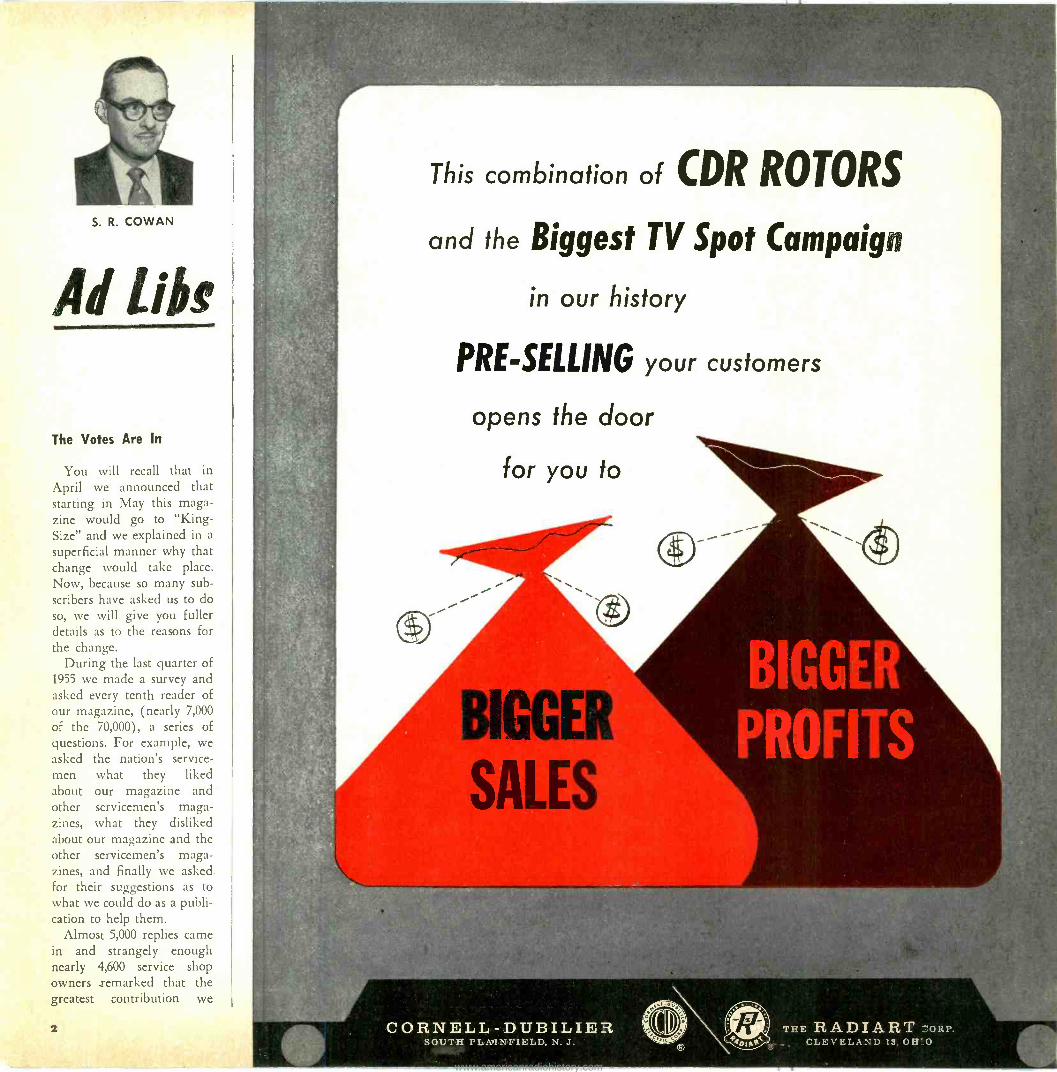
This combination of CDR ROTORS
and the Biggest TV Spot Campaign
in our history
PRE -SELLING your customers
opens the door
for you to
BILGE
SALES
CORNELL-DUBILIER, SOUTH PLAINFIELD, N. J.
THE RADIART CORP. 9 CLEVELAND 13, 01170
www.americanradiohistory.com
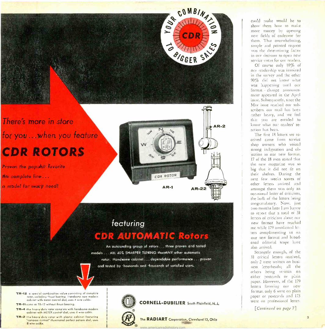
There's more in store
for you ... vihen you feature
CDR ROTORS Proven the popular favorite
the _omplete line .. .
a mpdel fir eva-y need!
MB/,f,9
\\ `y
CDR O
i
4./QGER
CDR ROTOR
AR -1
An outstandirg group of rotors ... three proven and tested
models ... ALL L10`.; SHARPER TUNING thanANY other automatic
rotor. Handsome cabinet ... dependable performance ... proven
and tested by housands and -housands of sat sfied use's.
TR -12 a special comb nation value consisting of complete rotor, including thrust bearing. Handsome new modern cabinet with meter control dial, uses 4 wire cable.
TR -11 same as TR -l2 without thrust bearing.
TR -4 the heavy duty rotor complete with handsome modern cabinet with METER control dial, uses 4 wire cable.
TR -2 the heavy duty rotor with plastic cabinet featuring 'compass control' illuminated perfect pattern dial, uses $ wire cable..
AR -2
CORNELL-DUBILIER South Plainfiield,N.J.
The RADIART Corporation, Cleveland 13, Ohio '43.11í1k
could make would be to show them how to make more money by opening new fields of endeavor for them. That overwhelming, simple a-nd pointed request was the determining factor in our decision to open new service vistas for our readers.
Of course only 10% of our readership was involved in the survey and the other 90% did not know what was happening until our format - change announce- ment appeared in the April issue. Subsequently, since the May issue reached our sub- scribers, our mail has been rather heavy, and we feel that you are entitled to
know what our readers' re-
action has been. The first 18 letters we re-
ceived came from service shop owners who voiced strong indignation and ob- jection to our new format. 17 of the 18 men stated that the new magazine was so
big that it did not fit on their shelves. During the next few weeks scores of
other letters arrived and amongst them was only an occasional letter of criticism, the bulk of the letters being congratulatory. Now, just two months later I am happy to report that a total of 31
letters of criticism about our new format have reached me while 179 unsolicited let-
ters complimenting us on our new format and broad- ened editorial scope have also arrived.
Strangely enough, of the 31 critical letters received, only 2 were written on busi- ness letterheads; all the others being written on either postcards or plain paper. However, of the 179
letters favoring our new format, only 6 were on plain paper or postcards and 173
were on professional letter -
[Continued on page 7]
www.americanradiohistory.com

11
ANCHOR LIGHTS
Y
PUSH BUTTON
STARTER SWITCH
BATTERY
t
a
STARTING MOTOR
NO. O BATTERY CABLE
FOR ALL OTHER WIRING USE
NO. 11 OR BETTER INSULATED WIRE
\ `INSTRUMENT PANEL GROUNDED TO ENGINE THRU OIL PRESSURE TUBE
GROUND TO MOTOR
RUNNING LIGHTS
II
_ II
COIL
G. A. F.
GENERATOR
Ip
DISTRIBUTOR IS
GROUNDED TO MOTOR
VOLTAGE REGULATOR
(Courtesy Gray Marine Motor Co.)
Fig. 1-Typical boat engine -battery system. (a) indicates ammeter, (s) switches.
Various electrical wiring systems used in
typical boat installations are discussed
in this installment. Precautions for the
prevention of accidents are also discussed.
PART 3-BOAT ELECTRICAL SYSTEMS
by ELBERT ROBBERSON
Marine Electronics Consultant
The Marine Electronic Business
5AS GAUGE TANK UNIT
THIS WIRE TO CENTER TERMINALL OF SOT CKE TIGN
IC 7STERHH LIGHT
GROUND WIRE FROM LIGHT SOCKET CASE TO ENGINE.J
CHRIS CRAFT
ENGINE - AL
6V
UGENERATIA co I REIAY_}
STARTER SOLINOID SWITCH
STARTER
lGL
`L1
(AL Gas GAUGE, '
' GtuGE
DASH LIGHTS
IB
Fig. 2-Circuit of more elaborate boat wiring system.
HORN RELAY
GROUNDED TO STEERING COLUMN,
OR TO OIL GAUGE.
J
HORN
BOW LIGHT
(Courtesy Chris-Craft)
TorE a piece of electronic equipment into a man's home and nobody has the least trepidation
about plugging it into an electrical outlet. But step foot over the side of the same man's boat,
and you're in a different world. To the person ac- customed to shore circuits, where Underwriters' and power -company rules keeps things fairly well in or- der, the usual small -boat electric system will seem like chaos.
You'll find power feed lines for different devices hooked onto the engine battery, the electric starter, the dashboard ammeter and (of all places) the engine oil gage!
But once you know how these lashups are derived, you can safely connect your own contribution to the boat's equipment. In badly confused situations, you might suggest a little electrical reorganization to the owner, which will make for a more reliable system.
Following this thought a little further, a service
4 SERVICE DEALER and ELECTRONIC SERVICING AUGUST, 1956
www.americanradiohistory.com
man who becomes an expert in this field may gain considerable extra business by taking care of the more complex electrical needs of a number of small ship- yards and boat dealers. Usually, there just isn't enough electrical work at any one small yard to sus- tain a specialist. So one of the engine mechanics is
called upon to double as electrician. The bad results of having electrical work performed by alumni of the corner gas station are evident wherever you find boats.
Simple Battery Systems
Aside from the personnel involved, most confusion in the boat electrical systems stems from the fact that the majority of today's boat engines are beefed-up automobile engines. In the interest of economy, auto- mobile wiring practice is followed, with one side of the battery grounded to the engine, and the engine block and various other masses of metal connected to it acting as ground returns. The polarity of the battery ground varies between engine manufacturers, and may change from year to year. In practice, it does not matter which side is grounded, just as long as there are no cross -polarity connections.
Fig. 1 shows a typical boat engine -battery system. One pole of the battery (in this case positive) and the ground returns of the charging generators, en- gine starter, ignition system, etc., are all connected to the engine block. Note that this ground and the lead over to the starting -motor solenoid switch are the only heavy conductors from the battery. Because of the high starter current there are no fuses in this heavy line.
The "hot" power feed for auxiliary and lighting circuits is a single wire run from the ungrounded terminal of the battery, as shown, to the dashboard ammeter, or more often this wire is connected to the solenoid. The wire, and branches from here on out, may be as light as No. 14 gage. Load circuits, and the generator, are connected to the other side of the ammeter, so that current going into or out of the battery makes the meter register "charge" or "dis- charge."
The simplest installations have no fuses or circuit breakers other than a toggle switch on the control panel. Although the schematic shows only the hot wire running out to the lights, with the return to ground at that point, two wires are actually used. One of them is the hot wire and the other the ground return. And here is where some odd connections may be found, such as terminals on the oil gage (which on the surface seems to have nothing to do with electricity). It has been common practice to ground auxiliary return circuits to any piece of hard- ware that connects metallically to the engine. Thus, steering columns, clutch controls, pressure gages con- nected to the engine by a copper tubing, and what- not will be found "doubling" as electrical conductors.
When a boat having such a system is originally
delivered, it may be entirely bare of any other elec- trical gadgets. However, the new skipper invariably loads on the equipment. Windshield wipers, horns, cabin lights are the starting point. As circuits are added, they may be connected to the ammeter until the terminal is full, and not one more wire can be squeezed under the nut. Then wires begin doubling up on the ignition switch and any other "hot" points that can be found. Things installed in the engine compartment, such as an electric bilge pump, are usually connected to the "hot" solenoid terminal or the battery. Thus, the electrical system turns into quite an amazing growth.
Semi -Protected Battery Systems
Figure 2 shows the circuit of a somewhat more elaborate boat wiring system. Note that load circuits are protected by fuses as well as having "on" -"off" switches. Some boats have the fuses behind the dash- board wherever room is found-the better jobs have a switchboard, installed in a cabinet or provided with a protective cover.
Note that the electric horn is fed from the battery side of the ammeter, rather than on the "load" side used for other circuits. This is because horn current is so high it would damage the ammeter. And, as in the case of the engine -starting motor, the horn is not fused.
Two or three -engine boats have complete battery systems for each engine, along the lines of either of the preceding. Although boats large enough to have more than one engine usually carry an auxiliary bat- tery system for lighting and power, some loads, such as the dashboard and navigating lights, will still be operated from the engine batteries. In this case, the circuits may be split up-for instance with the bat- tery of one engine supplying dashlights, and the bat- tery of the other furnishing electricity for running lights, etc.
In the interests of safety, some boats are wired with heavy (100 -ampere or more) knife or inclosed switches in the main battery leads to disconnect all load when the boat is not manned. And some have double -throw switches here, arranged so either bat- tery can be used to start either engine in an emer- gency. Because of the voltage loss in lengthy high - current cables, such switches are as close to the en- gines as possible-sometimes directly at the batteries.
Great caution is, of course, necessary when working around open switches (and all of the other battery - circuit terminals, for that matter). Six or twelve volts may sound "tame" to the technician accustomed to working in the thousands-but a heavy short cir- cuit can cause hundreds of amperes to flow in a
hurry. This is enough to blow up a tool in your face, melt a ring on your finger, or a wrist -watch band on your arm: very unpleasant, not to mention fire dan- ger.
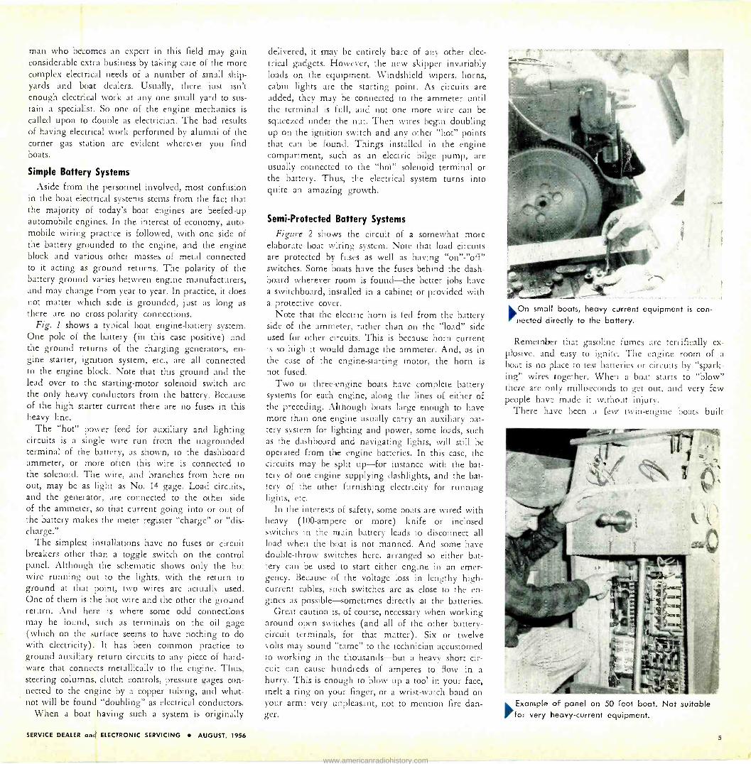
6On small boats, heavy current netted directly to the battery.
equipment is con -
Remember that gasoline fumes are terrifically ex- plosive., and easy to ignite. The engine room of a
boat is no place to test batteries or circuits by "spark- ing" wires together. When a boat starts to "blow" there are only milliseconds to get out, and very few people have made it without injury.
There have been a few twin -engine boats built
'Example of panel on 50 foot boat. Not suitable for very heavy -current equipment.
SERVICE DEALER and ELECTRONIC SERVICING AUGUST, 1956 5
www.americanradiohistory.com
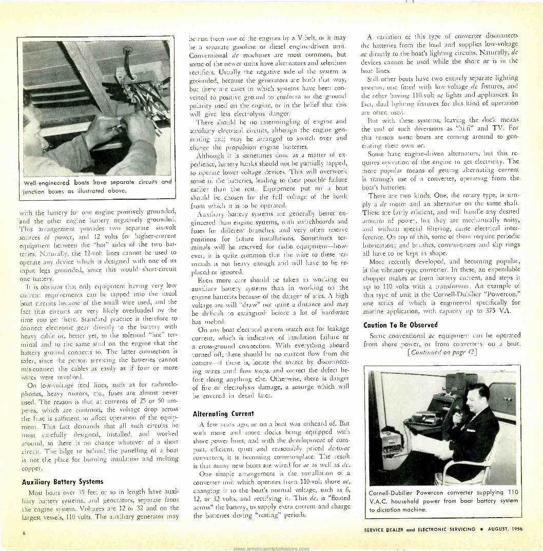
Well -engineered boats have separate circuits and
¡unction boxes as illustrated above.
with the battery for one engine positively grounded, and the other engine battery negatively grounded. This arrangement provides two separate six -volt
sources of power, and 12 volts for higher -current
equipment between the "hot" sides of the two bat-
teries. Naturally, the 12 -volt lines cannot be used to
operate any device which is designed with one of its
input legs grounded, since this would short-circuit
one battery. It is obvious that only equipment having very low
current requirements can be tapped into the usual
boat circuits because of the small wire used, and the
fact that circuits are very likely overloaded by the
time you get there. Standard practice is therefore to
connect electronic gear directly to the battery with
heavy cable or, better yet, to the solenoid "hot" ter-
minal and to the same stud on the engine that the battery ground connects to. The latter connection is
safer, since the person servicing the batteries cannot mis -connect the cables as easily as if four or more
wires were involved. On low -voltage feed lines, such as for radiotele-
phones, heavy motors, etc., fuses are almost never
used. The reason is that at currents of 25 or 50 am-
peres, which are common, the voltage drop across
the fuse is sufficient to affect operation of the equip-
ment. This fact demands that all such circuits be
most carefully designed, installed, and worked
around, so there is no chance whatever of a short
circuit. The bilge or behind the panelling of a boat
is not the place for burning insulation and melting
copper.
Auxiliary Battery Systems
Most boats over 35 feet or so in length have auxi-
liary battery systems, and generators, separate from
the engine system. Voltages are 12 or 32 and on the
largest vessels, 110 volts. The auxiliary generator may
be run from one of the engines by a V -belt, or it may
be a separate gasoline or diesel engine -driven unit. Conventional dc machines are most common, but
some of the newer units have alternators and selenium rectifiers. Usually the negative side of the system is
grounded, because the generators are built that way,
but there are cases in which systems have been con-
verted to positive ground to conform to the ground polarity used on the engine, or in the belief that this
will give less electrolysis danger. There should be no intermingling of engine and
auxiliary electrical circuits, although the engine gen-
erating unit may be arranged to switch over and charge the propulsion engine batteries.
Although it is sometimes done as a matter of ex-
pedience, battery banks should not be partially tapped,
to operate lower -voltage devices. This will overwork
some of the batteries, leading to their possible failure
earlier than the rest. Equipment put on a boat
should be chosen for the full voltage of the bank
from which it is to be operated. Auxiliary battery systems are generally better en-
gineered than engine systems, with switchboards and
fuses for different branches, and very often reserve
positions for future installations. Sometimes ter-
minals will be reserved for radio equipment-how- ever, it is quite common that the wire to these ter-
minals is not heavy enough and will have to be re-
placed or ignored. Even more care should be taken in working on
auxiliary battery systems than in working on the
engine batteries because of the danger of arcs. A high
voltage arc will "draw" out quite a distance and may
be difficult to extinguish before a lot of hardware has melted.
On any boat electrical system watch out for leakage
current, which is indicative of insulation failure or
a cross -ground connection. With everything aboard turned off, there should be no current flow from the battery-if there is, locate the source by disconnect-
ing wires until flow stops, and correct the defect be-
fore doing anything else. Otherwise, there is danger
of fire or electrolysis damage, a scourge which will
be covered in detail later.
Alternating Current
A few years ago, oc on a boat was unheard of. But with more and more docks being equipped with shore power lines, and with the development of com-
pact, efficient, quiet and reasonably priced dc -to -ac
converters, it is becoming commonplace. The result
is that many new boats are wired for ac as well as dc.
One simple arrangement is the installation of a
converter unit which operates from 110 -volt shore ac,
changing it to the boat's normal voltage, such as 6,
12, or 32 volts, and rectifying it. This dc, is "floated
across" the battery, to supply extra current and charge the batteries during "resting" periods.
A variation of this type of converter disconnects
the batteries from the load and supplies low -voltage
ac directly to the boat's lighting circuits. Naturally, dc
devices cannot be used while the shore ac is in the
boat lines. Still other boats have two entirely separate lighting
systems, one fitted with low -voltage dc fixtures, and
the other having 110 -volt ac lights and appliances. In
fact, dual lighting fixtures for this kind of operation are often used.
But with these systems, leaving the dock means
the end of such diversions as "hi-fi" and TV. For this reason some boats are coming around to gen-
erating their own ac.
Some have engine -driven alternators, but this re-
quires operation of the engine to get electricity. The more popular means of getting alternating current is through use of a converter, operating from the boat's batteries.
There are two kinds. One, the rotary type, is sim-
ply a dc motor and an alternator on the same shaft.
These are fairly efficient, and will handle any desired amount of power, but they are mechanically noisy,
and without special filtering, cause electrical inter- ference. On top of this, some of them require periodic lubrication; and brushes, commutators and slip rings all have to be kept in shape.
More recently developed, and becoming popular, is the vibrator -type converter. In these, an expendable chopper makes ac from battery current, and steps it
up to 110 volts with a transformer. An example of this type of unit is the Cornell-Dubilier "Powercon," one series of which is engineered specifically for marine application, with capacity up to 375 VA.
Caution To Be Observed
Some conventional ac equipment can be operated from shore power, or from converters, on a boat.
[Continued on page 42]
_
Cornell-Dubilier Powercon converter
V.A.C. household power from boat
to dictation machine.
supplying 110
battery system
6 SERVICE DEALER and ELECTRONIC SERVICING AUGUST, 1956
www.americanradiohistory.com

AD LIDS [from page 3]
heads. It would seem to me that the more progressive and businesslike type of service firm operator has rec- ognized the efforts we are expending on behalf of all professional servicemen much more so than those servicemen who do not even deem it worthwhile to use professional letterheads. However, to the latter group, and to all those who at pres- ent still feel a little "put out" because of our magazine's larger size, may we suggest that they just keep reading it and see if they don't eventu- ally agree that they are get- ting a better magazine than heretofore.
Moch Resigns From TESA
The Television Electronic Service Association of Chi- cagoland was established S
years ago, largely through the efforts of Frank J. Moch who became its first Presi- dent and who has held that position until recently when he resigned. In the mean- while, Mr. Moch was very active in the formation of NATESA (National Alli- ance of Television & Elec- tronic Service Associations) and he also assumed, and still retains, the presidency of that organization.
In the publicity release an- nouncing Mr. Moch's re- linquishment of his title with the local Chicago Serv- icemen's association he stated that as time passed the de- mands of the association work had become so over- whelming as to almost neces- sitate that the executive head devote his full time to it. We have noted that the same condition exists in sev- eral other parts of the coun- try where the Presidents of [Continued on page 8]
CHANNEL MASTER Explodes a Spectacular Campaign of *fr
NATIONAL CONSUMER MAGAZINE ADVERTISING
THE FIRST PROGRAM OF ITS KIND IN TV ANTENNA HISTORY
At Full -Color Ads .. .
reaching into. millions of American homes on the pages of these outstanding magazines:
BETTER 7v F(, TuR-ç FORA!MO
CHANNEL MASTER REVOLUTIONIZES ANTENNA MERCHANDISING! With large- scale national advertising and traffic -building local promotions, Channel Master now places TV anten12s on the same retail level as traffic lrppliances. It's actually a NEW WAY for you to sell antennas - anc sell more of them. Climb aboard the Channel Master brandwagon and tie in with tlese profit -making promotions. Get details from your Channel Mcster distributor.
NEW MARKET ' . NEW CUSTOMERS ... FOR THESE 2 GREAT NEW ANTENNAS
www.americanradiohistory.com

the respective servicemen's associations have out of the goodness of their hearts and with complete sincerity, al-
most lost their own busi- nesses in their efforts to co-
ordinate the efforts of the associations which they headed.
It thus becomes obvious that for an association to be truly effective it must find a
way or means of paving its top men, call them the Co- ordinators or Presidents, as
you will, some fee to reim- burse them for the services they are rendering when tak- ing losses from their normal business occupation.
Tube Developments Hardly a day passes
wherein some engineer does not conceive of the need for some new type of electronic tube. Only a fey' years ago tube manufacturers and radio -TV receiver equip- ment designers agreed that the 6S0 -odd tube types then available would suffice to meet any need in the then forseeable future. In fact, there was a movement for a
while to eliminate a great many tube types in the be- lief that many of those that were then available had al- ready become obsolete.
Progress will not stand still and for that reason the idea of reducing the num- ber of tube types in produc- tion was abandoned and from that day until this more and more new tubes have been conceived and put into production, and as this is written many other new ideas are in the drawing board stage.
Late last Fall General Electric announced the re-
lease of a tiny "Micro -Minia- ture" Ceramic Triode for UHF television receivers. The new all -metal and ceramic tube, which is about
8
CHANNEL MASTER® r"
the world's first "Travelling Wave" antenna
WHAT THE
"TRAVELLING WAVE" PRINCIPLE MEANS--
ideal phase relationships on all channels
optimum impedance matching on all channels
equal flow of current in all dipoles on all channels
fullest use of transmitted energy on all channels
IN SHORT - FABULOUS PERFORMANCE
ON ALL CHANNELS
SENSATIONAL 3- AND 5 -
ELEMENT MODELS!
Amazing T -W performance for sub- urban and near -fringe areas, too!
Wonderfully compact and rugged!
T -W 351 (5 -element)
T -W 352 (3 -element)
revolutionary new design provides picture quality never before possible
After two years of research-a completely new kind of VHF antenna, oper- ating on revolutionary new electronic principles. The T -W is Channel Master's greatest antenna achievement.
ALL THREE - IN ONE ALL -CHANNEL ANTENNA
O HIGHEST GAINS
Most powerful all -channel antenna ever developed. A single -bay T -W 350
(7 -element) actually OUTPERFORMS- any wide on h- ment Yagi each on low band channel.
© TOP FRONT -TO-BACK RATIOS
Low Band:
any stacked 10 -ele. ment Yagi on each high band channel.
Better than 10:1 on every channel. HIGHER THAN ANY 10 -ELEMENT SINGLE CHANNEL YAGI ON ALL CHANNELS!
High Band: From 5:1 to 12:1. HIGHEST RATIOS OF ANY SINGLE
ALL CHANNEL ANTENNA.
O GREATEST MECHANICAL STRENGTH
The most rugged antenna ever built. "Twin Truss" design amplifies the strength of every component. And new mechanical features add still greater durability ...
I"Twin Booms'.'... Two full-length crossarms-really rugged and rigid.
2 "Super-Nests"One heavy-duty mast clamp on each crossboom .
A TOTAL OF 4 U -BOLTS! Antenna cannot move.
"Line -Lok" Twinlead can't possibly tear away from terminals..
PROOF OF THE SUPERIORITY OF "TWIN -TRUSS" CONSTRUCTION
Look at the dramatic result when equal weights are hung on a T -W and a standard 10 -ele- ment Yagi!
Write for complete technical literature.
&Trod. h14 4.p. U.S. Pa. OUI
www.americanradiohistory.com

CHANNEL MASTER"
new "Metro -Dyne" tuning obsoletes "Ra bbit-Ears "
howman
the first basic indoor antenna improvement in over 10 years
Channel Master sets an exciting new trend in TV antennas with the howman. In appearance (so important in the sale of indoor antennas) the
Showman is in a dazzling class by itself. Yet, it's a complex electronic instru- ment-the most powerful indoor antenna yet developed by modern science!
The SHOWMAN is perfect for color reception, tops for black -and -white. And, it provides excellent FM reception, too!
ACTUALLY TUNES OUT "GHOSTS" AND "SNOW"! MORE EFFECTIVE THAN ANY OTHER INDOOR ANTENNA!
With ordinary indoor antennas
With the Showman
Metropolitan areas, where indoor antennas are most frequently used, are often subject to the most severe "ghost- ing" problems. Only the SHOWMAN, with its sensational new Metro -Dyne tuning, can overcome this difficulty. You'll be amazed at the job it does on all kinds of interference. Test it for yourself! Demonstrate it for your customers!
Channel Master stands squarely be- hind every SHOWMAN you sell. An unconditional money -back guarantee assures your customer of complete satisfaction.
UNCONDITIONAL MONEY -BACK GUARANTEE
Available in three "decor designs"- "High fashion' to blend with any setting. packaging. Mahogany Blond Ebony
Attractive, convenient., Ideal for display.
and Gold
model no. 3900
and Gold
model no. 3901
and Silver
model no. 3902
'SSIMe!!O
CHANNEL MASTER CORP [I(IMrfttt, y v the world's largest manufacturer of television antennas and aeresaodal.
what makes the
bowman different?
FABULOUS
"METRO -DYNE"
TUNING! The Metro -Dyne 12 -Channel "Variable Inductance" Tuner
Ordinary switch -type antennas work by connecting various element
into different combinations. METRO -
DYNE tuning, on the other hand, is
"variable inductance" tuning, using
the same tuning principles as any TV
set. It is the first broad band antenna which can be tuned to a specific
channel so that it exhibits the band width characteristics of a single -chan-
nel Yagi. This selectivity cuts down tremendously on "electronic noise" and interference. A built-in auto transformer maintains a constant 300
ohm impedance match.
EASY OPERATION: the Showman is calibrated by channels. Just turn
it to the same channel number as the
TV set. No arms to adjust; no guess-
work or error
(opptia11156. Channel M,..,, Corp.
3/8" long and 5/16" in di- ameter, was given the type number 6I3Y4. This particu- lar tube was rated to operate with a noise factor of ap- proximately 8 db and a
power gain approximating 15 db when operated at 900
mc.
As one can see by glancing at our front cover this month the 6BY4 tube features micro spacing of elements and a
grid of approximately 1,000
turns per inch. The simpli- fied design permitted a rela- tively low list price.
The particular tube under discussion is simply the fore- runner of an entirely new engineering concept and line of tiny electronic tubes from diodes to complex multi - element tubes, all of which will have application in mo- bile and industrial commu- nications equipment, , air- borne and mobile radar, industrial controls, etc. Be-
cause of its ruggedness this type of design permits fur- ther exploration in the Guided Missile program, but even more important is the present day application of the tube in UHF circuits. Be-
cause at present the FCC is
becoming more and more conscious of the potential of UHF in television, (not that we agree with their philos- ophy) it is incumbent upon all developmental engineers to reinvestigate and continue their research into the de- velopment of components that will be required for combination UHF -VHF tel- evision transmission and re- ception usage.
It is said that history re-
peats itself. How true! Not very long ago the entire in- dustry was trying to meet the demands for UHF tun- ers. Then UHF came upon bad days and it was only recently that a revitalization program became mandatory.
9
www.americanradiohistory.com
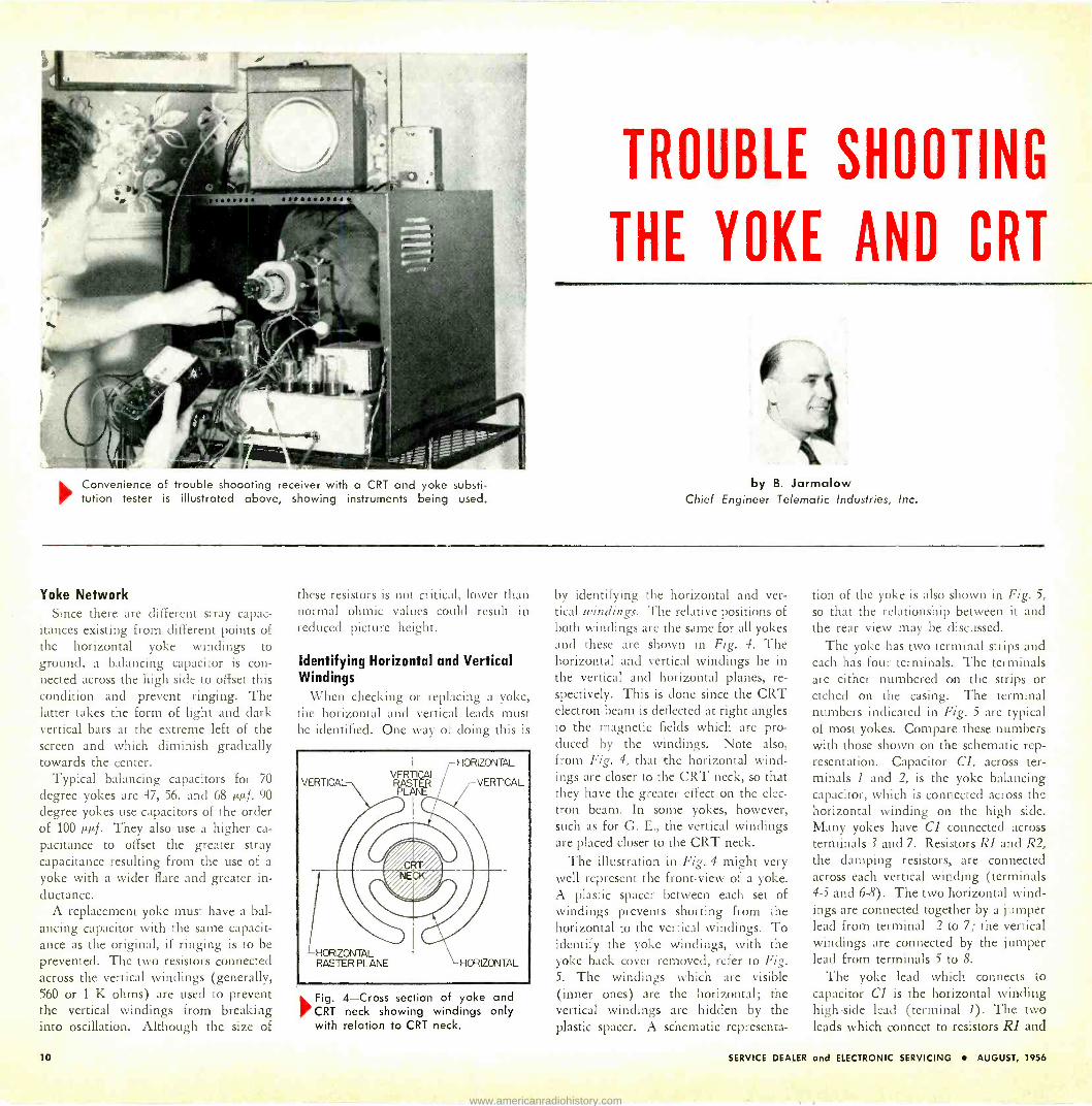
Convenience of trouble sh000ting receiver with a CRT and yoke substi- tution tester is illustrated above, showing instruments being used.
TROUBLE SHOOTING
THE YOKE AND CRT
by B. Jarmalow Chief Engineer Telematic Industries, Inc.
Yoke Network Since there are different stray capac-
itances existing from different points of the horizontal yoke windings to ground, a balancing capacitor is con- nected across the high side to offset this condition and prevent ringing. The latter takes the form of light and dark vertical bars at the extreme left of the screen and which diminish gradually towards the center.
Typical balancing capacitors for 70
degree yokes are 47, 56, and 68 µµf. 90
degree yokes use capacitors of the order of 100 µµf. They also use a higher ca-
pacitance to offset the greater stray capacitance resulting from the use of a
yoke with a wider flare and greater in- ductance.
A replacement yoke must have a bal- ancing capacitor with the same capacit- ance as the original, if ringing is to be prevented. The two resistors connected across the vertical windings (generally, 560 or 1 K ohms) are used to prevent the vertical windings from breaking into oscillation. Although the size of
these resistors is not critical, lower than normal ohmic values could result in reduced picture height.
Identifying Horizontal and Vertical Windings
When checking or replacing a yoke, the horizontal and vertical leads must be identified. One way of doing this is
VERTICAL VERTICAL E
PLANE
HORIZONTAL RASTER PLANE HORIZONTAL
HORIZONTAL
VERTICAL
'Fig. CRT with
4-Cross section of yoke and neck showing windings only relation to CRT neck.
by identifying the horizontal and ver- tical windings. The relative positions of both windings are the same for all yokes and these are shown in Fig. 4. The horizontal and vertical windings lie in the vertical and horizontal planes, re-
spectively. This is done since the CRT electron beam is deflected at right angles to the magnetic fields which are pro- duced by the windings. Note also, from Fig. 4, that the horizontal wind- ings are closer to the CRT neck, so that they have the greater effect on the elec- tron beam. In some yokes, however, such as for G. E., the vertical windings are placed closer to the CRT neck.
The illustration in Fig. 4 might very well represent the front -view of a yoke. A plastic spacer between each set of windings prevents shorting from the horizontal to the vertical windings. To identify the yoke windings, with the yoke back cover removed, refer to Fig. 5. The windings which are visible (inner ones) are the horizontal; the vertical windings are hidden by the plastic spacer. A schematic representa-
tion of the yoke is also shown in Fig. 5,
so that the relationship between it and the rear view may be discussed.
The yoke has two terminal strips and each has four terminals. The terminals are either numbered on the strips or etched on the casing. The terminal numbers indicated in Fig. 5 are typical of most yokes. Compare these numbers with those shown on the schematic rep- resentation. Capacitor Cl, across ter- minals I and 2, is the yoke balancing capacitor, which is connected across the horizontal winding on the high side. Many yokes have Cl connected across terminals 3 and 7. Resistors R1 and R2, the damping resistors, are connected across each vertical winding (terminals 4-5 and 6-8). The two horizontal wind- ings are connected together by a jumper lead from terminal 2 to 7; the vertical windings are connected by the jumper lead from terminals 5 io 8.
The yoke lead which connects to capacitor Cl is the horizontal winding high -side lead (terminal 1). The two leads which connect to resistors RI and
10 SERVICE DEALER and ELECTRONIC SERVICING AUGUST, 1956
www.americanradiohistory.com

A thorough coverage of yoke construction, operation, and
trouble shooting procedures. Chart is provided.
Part II
R2 are the vertical winding leads. The high and low sides of the yoke are difficult to determine, although ter- minal 4 is usually the high -side. The fourth remaining unidentified lead connects to the horizontal winding low side (terminal 3). Although set manu- facturers do not follow any lead color code in particular, it will be found that many use blue (high side) and red (low side) for the horizontal and brown (high side) and green (low side) for the vertical.
Some yokes incorporate a resistor (about 1K) in series with the balancing capacitor. See R3 in Fig. 6A. Still other yokes omit the damping resistors, R1
and R2. In direct -drive yokes, resistors RI and R2 are not used. Instead, a
capacitor (about 270-µµf) is connected
TERMINAL.BORÓA
STRIP
SVLCER,
CASIN
HORIZONTAL WINDING
between the horizontal and vertical windings (C2 in Fig. 6B) which mini- mizes yoke cross -talk. Cross -talk results in a moveable, dark horizontal hum bar(s) in the picture. Some direct -drive yokes, such as Motorola's have the ver- tical and horizontal windings jumped (terminals 3 and 8, in Fig. 6C) and capacitor C2 is not used.
Many of the yokes used in newer sets have five leads. The fifth lead connects to the center point of the horizontal winding, through a resistor, about 1K, as shown in Fig. 6D. This lead connects to the flyback transformer to provide better yoke balancing. To make the re-
placement yoke equivalent to the five -
lead yoke, simply connect an additional lead to the horizontal winding center - tap. In most cases, the balancing ca -
HORIZONTAL WINDING
LEADS GOING TO PINS No.1, 3,,4,AND 6.
RI
TERMINAI. BOARD STRIP
(Courtesy: Reprinted from Howard Sams "Servicing TV Sweep Systems," by J. Dines)
Fig. 5-Similar cross section as that of Fig. 4; in this case
ali parts are shown with corresponding schematic on the right.
pacitor, Cl, will be included. Some
manufacturers, such as Magnavox and
Philco, leave these capacitors out. Syl-
vania and G.E., among others, connect the two horiz. windings in parallel (Fig. 6E), which eliminates the need for a balancing capacitor. This yoke
operates in the same way as two hori- zontal windings connected in series.
Consequently, a replacement yoke, which has two horizontal windings in
series, may replace this yoke by con-
necting it to the same taps on the fly-
back. In this case, a balancing capacitor must be connected across the high side
of the horizontal winding to eliminate ringing. Several different values may
have to be tried.
Removing a "Frozen" Yoke
Yokes which arc defective, or which have not been disturbed for a very long period of time, tend to adhere, or
"freeze," to the CRT neck. They should not be forced, lest the CRT be broken. One way to loosen the yoke is to apply 115 volts ac, for about 10 seconds, across
the horizontal windings after the yoke leads have all been disconnected. The yoke will become warm, and twisting it while pulling it away from the CRT should free it. If necessary, repeat this procedure several times.
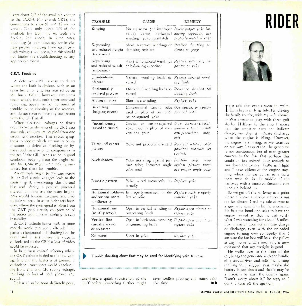
Yoke Troubleshooting Chart
The chart on page 12 may be used as a reference to identify yoke troubles quickly. The causes and remedies of
the various troubles are also indicated.
Using 5AXP4 for 24 or 27 inch CRTs
High voltages, of the order of 20 kv, are usually needed to operate 24 or 27
inch, 90 -degree CRTs. When the 5AXP4 is used as a temporary substitute for such a tube, the high voltage may damage it permanently. Furthermore, it is necessary to properly load down the flyback circuit of the receiver. To satisfy these conditions, it has been found that a 150 megohm voltage divider network must be used, as shown in Fig. 7. Fif- teen 10 meg, 1w, resistors form the divider. Mounting the resistors on a
terminal board will make the divider more compact and reduce the chances of arcing between resistors. An alligator clip is attached to each end of the string
Fig. 6-Connections for different yoke types.
and a high voltage wire (with 2nd
anode suction cap) is attached to the
junction of the fifth and sixth resistors.
The entire resistor string is then taped with high -voltage plastic, such as vinyl.
For a 24 inch CRT, whose high volt-
age requirement is less than that of a
27 -inch CRT, alligator clips t$1 and #$2
are connected to the set by lead and
chassis ground, respectively. This de -
ALLIGATOR CLIP » 1
(TO H.V. LEAD OF SET)
ALL RESIST 1 W. (TOTAL
TERMINAL BOARD
TO 5AXP4 2ND ANODE
ALLIGATOR CLIP *2_I (TO CHASSIS GROUND)
Fig. 7-Voltage divider for using 5AXP4 tube as a substitute for 24" and 27" high voltage tubes.
SERVICE DEALER and ELECTRONIC SERVICING AUGUST, 1956 11
www.americanradiohistory.com
livers about 2/3 of the available voltage to the 5AXP4. For 27 -inch CRTs, the connections to clips ;1 and #2 are re- versed. Now only about 1/3 of the available h -v from the set feeds the 5AXP4 2nd anode. In some cases, blooming (a poor focusing, low -bright- ness picture resulting from insufficient high -voltage) will occur, but this should not hinder the troubleshooting to any appreciable extent.
C.R.T. Troubles
A defective CRT is easy to detect where the fault is obvious, such as an open heater or a screen marred by an ion burn. Often, however, symptoms occur which, from both experience and reasoning, appear to be the result of trouble in the circuitry of the receiver, and do not seem to have any connection with the CRT at all.
When electrical leakages or shorts occur between elements of the CRT gun assembly, voltages are coupled from one circuit into another. This causes symp- toms to appear which are similar to in- dications of defective blacking or by- pass condensers or other components in the set. If the CRT seems to be in good condition, judging from the brightness and focus, one might start looking any- where but there for trouble.
An example might be the case where 1st or 2nd anode voltages leak to the control grid, overcoming the normal bias and placing a positive potential thereon. In most sets the raster bright- ness would become excessive and irre- ducible to zero. In some older sets how- ever, where the sync signal is taken from the CRT grid circuit, compression of the pulses would occur resulting in sync instability.
A CRT cathode -heater leak in some models would produce a 60 -cycle hum pattern (horizontal half -shading) of the raster and in sets where the video is cathode fed to the CRT a loss of video could be expected.
In brightness control schemes where the CRT cathode is tied to the low volt- age line and the heater is at ground, a
cathode to heater short would knock out the front end and I.F. supply voltage, resulting in loss of both picture and sound.
Unless all indications definitely point
TROUBLE CAUSE REMEDY
Ringing No capacitor (or improper Insert proper yoke bal -
value) across horizontal ancing capacitor; us(
winding; yoke mismatch properly matched yok(
Keystoning Short in vertical windings or Replace damping re and reduced height damping resistors sistors or yoke (trapezoid)
Keystoning Short in horizontal windings Replace balancing ca -
and reduced width or balancing capacitor pacitor or yoke (trapezoid)
Upside-down Vertical winding leads re- Reverse vertical wind - picture versed ing leads
Horizontally Horizontal winding leads re- Reverse horizontal reversed picture versed winding leads
Arcing in yoke Short in a winding Replace yoke
Barrelling Conventional wound yoke Use cosine, or cosine - (bulging raster) used in place of cosine or squared yoke
cosine -squared yoke
Pincushioning Cosine, or cosine -squared Use conventional - (caved -in raster) yoke used in place of con- wound yoke, or install
ventional yoke anti -pincushion mag- nets
Tilted, off -center Yoke not properly oriented Reorient relative yoke picture position; readjust set
controls
Neck shadow Yoke not snug against pic- Position yoke snug ture tube; incorrect angle against picture tube; yoke used use proper angle yoke
Bow -tie pattern Yoke wired incorrectly in- Replace yoke ternally
Horizontal foldover Improperly -matched, or de- Replace with properly and/or horizontal fective yoke matched yoke nonlinearity
Horizontal line Open in vertical winding or Repair open circuit or (usually wavy) connecting leads replace yoke
Vertical line Open in horizontal winding Repair open circuit or (usually wavy) or connecting leads replace yoke or no raster
No raster Short in yoke Replace yoke
Trouble shooting chart that may be used for identifying yoke troubles.
;AIIIIIIIIIIIIIIIIIIIIIIIIIIR' IIIIIIIIIIIIIIIIIIIIIIIIIII IIIIIIIIIIIIIIIIIIIIIIIIIIIIIIIIIIIIIIIIIIIIIIIIIIIIII IIIII IIIIIIIIIII 11111I I:'lllllllllllll IIIIIIIIIIIIIIIIIIIIIIiIII!IIIIIIIIIIIIIIIII IIIIII IIIIIIIIII IIIIIIIIIIIIIII Illlllllllllllllllllllllllllllllllllllltlllll Illllllllllllllf IIIIIIIIIIIIIIIIIIIIIIIIIIIIIIIIIIIIIIIIIIIIIIIIIIIIIIIIIIIIIIIIIIIIIIIO
elsewhere, a quick substitution of the save needless probing and much valu - CRT before proceeding further might able time.
RIDER
IT is said that events occur in cycles. Let's begin early in July. I'm driving
the family chariot, with my wife aboard, to Westchester to play with three golf sharks. Halfway to the club I notice that the ammeter does not indicate charge, nor does it indicate discharge when the engine is idling. However, the engine is running, so we continue on our way. I suspect that the generator is not functioning, but of even greater concern is the fear that perhaps this condition has existed long enough to run down the battery. Traffic isn't light and I have visions of the engine stop- ping when the car comes to a halt; there we'd sit, in the middle of the parkway with a hundred thousand cars lined up behind us.
So we get off the parkway at a point where I know a service station is not too far distant. I tell my tale of woe to a guy who is said to be the mechanic. He lifts the hood and asks to have the engine revved so that he can verify what I was watching for about 18 miles. The ammeter does not indicate charge or discharge, even with the unloaded engine turning over so rapidly that I
am sure the fan belt will leave the pulley at any moment. The mechanic is now convinced that my eyesight is good.
He walks over to the front of the car, bangs the generator with the handle of a screwdriver and tells me to stop the engine. I suggest that maybe the battery is run down and that it may be a problem to start the engine again. "Don't worry about it," he says, so I
don't. I turn off the ignition.
12 SERVICE DEALER and ELECTRONIC SERVICING AUGUST, 1956
www.americanradiohistory.com

SPEAKS
by JOHN F. RIDER
"Dean of America's Radio Servicemen"
He removes the regulator box cover, peers at the relays and pushes one of them while I'm looking at the ammeter. It shows a momentary discharge. Nov he says, "Start the engine." I try. A few weak grunts of the starter-then nothing. Now comes a profound com- ment from the genius. "The battery is
dead" (as if I didn't know it). His next remark is even better. "I think you ruined the battery; you'll probably need a new one," says he. "You also need a new generator" is the inevitable follow-up.
After a few moments spent trying to recover my breath, I suggest that we substitute a charged battery for mine to get the engine started. He agrees and goes inside the shop. Shortly thereafter, he returns and calmly tells me he's fresh out of charged batteries, but he has one on the line that will be usable in about 30 minutes.
By this time I am 20 minutes late for my date and my wife is slightly per- turbed, which is a polite way of saying it. But we wait, and finally the venture is crowned with success. He shunts the old battery with the charged one and the car is running, but the ammeter shows nothing. So I suggest that maybe it would be a good idea to measure the output from the generator to find out whether it is generating anything more than the wind from the ventilating fan. My mechanic friend doesn't think it is
necessary; he insists that he knows his business. Anyway, he has no equipment for checking the voltage.
Now I'm one hour late for my date [Continued on page 47]
WESTERN UNION "OPERATOR 2S"
g. laA[.t l(, SERVICE
Raytheon Bonded Dealers are listed with Western Union "Operator 25". Po- tential customers needing TV or Radio repairs need only call Western Union by number and ask for "Operator 25". She'll give them the name and phone number of the Raytheon Bonded Dealer nearest the customer. More business for Bonded Dealers.
NATIONAL ADVERTISING
10 million readers a month will be urged to use Raytheon Bonded Electronic Technicians for their TV and Radio repairs. A powerful, ex- clusive advertising campaign designed solely to stimulate service business for Raytheon Bonded Dealers.
only (RAYTHEO) BONDED DEALERS have all these business -building assets
RAYTHEON BONDED BACKING
r,hrv 14ec TM. r.,...,+sh,wa
franks ïiaAio & Ircicrosin" [tbltt
.F. ./Lr. -,, 1
IIAYTHEON/:.
BONiBEB BIFITHO\tl TFIIN\YAS
v.
Xes. eiregfiüttfliAlin it"'"` dfts -frt" ils ïts
The Bonded Electronic Technician guarantee on all radio and television repair work and parts is backed by a bond issue through one of America's largest insurance companies. This important support creates customer confidence and results in more customers - more profit and more prestige.
tHEY'RE p ro,,
EXCLUSIVE RAYTHEON BONDED DEALER
PROMOTION MATERIAL
Raytheon Bonded Dealers receive a registered Bond Certificate, Decals, ID Cards, Creed Displays - all designed to bring attention to their Bonded status. Special ads, mailing pieces and countless sales and shop aids are available exclusively to Raytheon Bonded Dealers.
Your sponsoring Raytheon Tube Distributor will be happy to discuss the Raytheon Bonding program with you. Better call him today.
RAYTH EON MANUFACTURING COMPANY Receiving and Cathode Ray Tube Operations
Newton, Mass. Chicago, III. Atlanta, Ga. Los Angeles, Calif. Raytheon makes Receiving and Picture Tubes, Reliable Subminiatureand Miniature Tubes, Sernicon-
all these S ductor Diodes, Power Rectifiers and Transistors, Nucleonic Tubes, Microwave Tubes
aaYTHEóH
Free/4c, in g`'/eclwslcs
SERVICE DEALER and ELECTRONIC SERVICING AUGUST, 1956 13
www.americanradiohistory.com

>Fig. 1 A-Checking level of flyback waveform demodulator probe and voltmeter.
with
Construction, test applications, and limitations of
the scope demodulator probe. Various examples and
measurement techniques are discussed and illustrated.
Oscilloscope Probes
by Robert G. Middleton
Chief Field Engineer, Simpson Electric Co.
M:,NUFACTL'RERS of oscilloscope probes receive many inquiries
concerning the application of probes in
radio and television service. Today, nearly all technicians have a comple- ment of scope probes available, but the use of these probes is not always com- pletely understood. It is the purpose of this article to outline the general tech- niques which find daily application at the bench.
Application of the Detector Or Demodulator Probe
Figure 1 shows applications of a detector probe of the demodulator type, which is used with an oscilloscope. This probe utilizes a voltage -doubler circuit arrangement, which effectively doubles the sensitivity of indication; the circuit is shown in Fig. 2.
A demodulator probe for scope use differs from a detector scope used with a VTVM in one essential respect: the demodulator probe is arranged to recti- fy and filter the carrier component of the signal, but passes the modulation component of the signal to the scope. A VTVM detector probe, on the other hand, rectifies and filters both the car- rier component and the modulation
250,uu PROBE .A 7 /P
1N34A
SHIELDED CABLE
/N3 4A -
GND.
//4 MEG.
VERT-\
ro SCOPE GND. -
Fig. 2-Circuit arrangement of volt- age -doubler demodulator probe.
component of the signal. The circuit arrangement of a VTVM detector probe is shown in Fig. 3.
A scope demodulator probe finds its most popular application in signal -trac- ing procedures. For example, with a
fairly strong TV signal applied to the antenna -input terminals of a TV re-
ceiver, the demodulator probe can be to check the progress of the signal
from the output of the rf tuner up to the input of the picture detector. Thus, dead or weak if stages can be quickly localized.
There are some limitations in this signal -tracing procedure which should
he recognized. First, the amount of scope deflection which is obtained is
not necessarily an accurate measure of the stage gain, because the probe loads the if circuit substantially, and the value of signal voltage delivered by the probe is sometimes less, and sometimes more, than the true signal voltage. The probe has appreciable input capacitance, which detunes the stage under test to some extent. If the detuning happens
Fig. 1B - Checking video signal level to
picture tube with probe.
to occur in a direction which peaks up the amplifier response, the apparent signal voltage is increased. But if the detuning occurs in a direction which broadens the over-all response, the ap- parent signal voltage is decreased.
Because of the detuning action of the probe, it is advisable to make a double check at each tube-one check at the grid terminal, and ano her check at the plate terminal. In a few cases, a satis -
14 SERVICE DEALER and ELECTRONIC SERVICING AUGUST, 1956
www.americanradiohistory.com

factory test may be obtained at the grid, whereas at the plate the application of
the probe causes the amplifier to break into oscillation. Oscillation has the same
appearance on the scope screen as a
dead stage, but a VTVM at the output of the picture detector will show a large jump in dc voltage when the probe is
applied. Experience is the best teacher in this regard, and makes it possible to obtain satisfactory preliminary tests with a signal -tracing probe and scope.
Another limitation in the signal -trac- ing procedure is the attenuation of the high -frequency component of video sig-
nal which is incurred in its passage through the probe. It will be noted that the vertical sync pulse comes through and is displayed in reasonably undis- torted form on the scope screen. But the horizontal sync pulse is both attenuated and integrated, and appears as a low- level sawtooth waveform. For this rea-
O/MFD. 3.9 MEG.
INPUT +--' TO
TESTER
G. ND.
/N3 4
TO
TESTER
Fig. 3-Circuit arrangement of a
typical VTVM detector probe.
son, signal -tracing procedures are ac-
complished to best advantage when the scope is deflected horizontally at a 60 -
cycle rate. A more satisfactory method of sig-
nal -tracing is realized when the receiver is energized by the output from an AM or FM generator. The signal level is
then under the operator's control, and the modulation frequency does not ex- ceed 400 cycles, so that the maximum efficiency of the demodulator probe is
realized. If an AM generator is utilized, the modulated rf output (at the chan- nel frequency) is applied to the an- tenna -input terminals of the receiver, and the output level is advanced until
Makers of a complete line of fuses for home, farm, commercial, electronic, automotive and industrial use.
8_.i
Safeguard against troubles and complaints - by standardizing on dependable BUSS FUSES!
BUSS fuses give you double pro- tection against loss of customer good- will because ... BUSS fuses blow only to protect - never needlessly. To make sure of proper operation, BUSS fuses are tested in a sensitive electronic device that automatically rejects any fuse not correctly calibrated, properly constructed and right in all physical dimensions.
When you sell or install BUSS fuses ... you are safeguarding the users of equipment against irritating, useless shutdowns due to faulty fuses blowing needlessly. And you are providing them with maximum protection against damage caused by electrical faults.
Most important, the dependability of BUSS fuses helps you avoid costly,
unnecessary callbacks. And the proper operation of BUSS fuses helps safe- guard your reputation for quality and service.
Why settle for anything less than BUSS quality in fuses? The complete BUSS fuse line includes: standard types, dual -element (slow blowing), renewable and one-time types - in sizes from 1/500 amp. up . . . plus a companion line of fuse clips, blocks and holders.
For more information avail able on BUSS and Fusetron small dimension fuses and fuse - holders ... Write for bulletin SFB.
BUSSMANN MFG. CO. (Div. of McGraw Electric Co.) University at Jefferson, St. Louis 7, Mo.
USETRD TRUIFWOIIIXT NAM" fed
TM. SERVICE DEALER and ELECTRONIC SERVICING AUGUST, 1956 15
www.americanradiohistory.com

i
HELPS YOU MASTER
COLOR TV PRINCIPLES
AND PRACTICES
only $695
ORDER BELOW
SAMS BOOKS keep You ahead in
ELECTRONICS
"C tOR V TRAINING MANUAL" THE NEW BOOK THAT PREPARES YOU FOR SUCCESSFUL COLOR TV SERVICING
Written by C. P. Oliphant and Verne M. Ray, of the Howard W. Sama editorial staff, in practical, down-to-earth language you can understand. Presented in 3 comprehensive sections. SECTION I: Principles of the Color TV System (includes chapters on Colorimetry; Requirements of the Composite Signal; Make -Up of the Color Picture Signal). SECTION II: Color Receiver Circuits (chapters on RF and IF Circuits; Video, Sync and Voltage Supply Circuits; Bandpass - Amplifier, Color -Sync and Color -Killer Circuits; Color Demodulation; Matrix and Output Circuits). SECTION III: Servicing the Color Receiver (chapters on Setting Up the Color Picture Tube; Aligning the Color Receiver; Trouble -Shooting; Test Equipment Required). Appendices include Equations, Vectors, Color -blocks, Colorplates, Glossary. A comprehensive training course that helps you qualify for Color TV servicing. 260 pages, 8y x 11"; profusely illustrated. Postpaid, only ... $695
Sams books cover every phase of Electronics for the service technician, engineer,
student or experimenter. Listed below are a few of the many valuable Sams books available at electronic
parts distributors and leading book stores.
USE THIS ORDER FORM
COLOR TELEVISION TRAINING MANUAL
Analyzing and Tracing TV Circuits. Presents - a new approach to TV servicing. 168 pages, 8Hx11 $3.00
E TV Service Data Handbook. Most frequently needed charts, tables and formulas re- quired in TV servicing and installation. 112 pages, 5% x 8 %" $1.50
E Principles & Practices of Telecasting Operations. Discusses equipment and techniques. Covers such subjects as: TV Cameras; Control Rooms; Fundamentals of Studio Lighting; Relay Systems; Maintenance Practices; Technical Production; etc. 600 pages; 6 x 9"; illustrated $7.95
o Radio Receiver Servicing. Covers the basic receiver types-gives time -saving hints for solving basic troubles, such as dead set, weak set, noisy set, etc. 192 pages; 53' x 8%" $2.50 So You Want to Be Ham. Tells you what you need to know about getting your license and acquiring equipment. Covers such subjects as: Conquering the Code; Getting our Ticket; Going on the Air; Electronics as a Career; etc. 196 pages; 5% x 8W; illustrated $2.50
o Servicing TV Sweep Systems. Describes the operation, circuit function and circuit variations of vertical and horizontal sweep systems common to most TV receivers. Tells how to analyze circuits; trouble- shoots for you. 212 pages; 5% x 8.4"; illustrated $2.75 The Recording and Reproduction of Sound. - Widely used by Audio engineers, Hi-Fi enthusiasts, broadcasting stations and recording studios. Authoritative chapters cover: behavior of sound waves; basic recording methods; lateral disc recording; micro -groove recording; phono reproduc- ers; microphones; home music systems; P.A. systems; amplifiers; tuners; etc. 810 pages; 6 x 9"; illustrated ...... $7.95
HOW TO UNDERSTAND AND USE
TV TEST INSTRUMENTS Completely revised and enlarged to in- clude latest data on instruments used for Color TV Servicing. Covers use of VTVM's Signal Generators, Sweep Signal Genera- tors, Scopes, Video Signal Generators, Field Intensity Meters and Voitage Cali- brators. 208 pages, 8y, x 11" $3.50 Phototact Television Course. Gives a clear complete understanding of TV principles, operation, practice. Used by thousands of students. 208 pages, 8.4 x 11" $3.00
0 Atomic Radiation, Detection and Measurement. Provides basic understanding of nuclear science and its applications. Thoroughly covers and illustrates circuitry and oper- ation of the many types of detection devices. 200 pages; 5j x 84" $3.00
OBasic Radio Manual. Provides all the basic facts on theory, definitions, components. Includes section devoted to actual projects that translate theory into practice. 248 pages; 8% x 11"; illustrated $5.00
Attenuators, Equalizers and Filters. Describes design. application and theory of operation of even' type st Alteouator. Equalizer and 'Wave Filter. Covers all types of equalization and at- tenuation used in audio recording and repro- ducing systems, lend, professin'la I and home - type. Includes chapters on ltl-F, crosso, er net- works. Provides time -saving charts w hieh per- mit easy determination of component values re- quired in designing equalizers and filters. In- talnable to audio ter hnlcians and engineers. 176 pages: 5'b x S'!-": fully ìll ustre tr.'. De- luxe hard binding - - - -- $4.00 Paper -hound edition $2.75
There is an authoritative Sams book on virtually any Electronic subject in which you're interested. Check be- low for FREE Book List describ- ing all Sams books.
Send Book List
IuHOWARD W. SAMS & CO., INC. Order from your Parts Jobber today, or mail to Howard W. Sams & Co., Inc., Dept. 4-H6 2201 East 46th St., Indianapolis 5, Indiana. Send books checked above. My (check) (money order) for $ is enclosed.
Name
Address
City Zone State
L (outside U.S.A. priced slightly higher)
Look for SAMS BOOKS
on the "Book Tree" at your Parts
Distributor
i
Fig. 4-Network across probe input permits response curve visualization on the scope screen.
an indication is obtained at the output of the rf tuner. Most AM generators utilize 400 -cycle sine -wave modulation, so that the indication obtained on the scope screen is a sine waveform.
If an FM generator is utilized in the test, a sweep signal is applied to the antenna -input terminals of the receiver at channel frequency. The blanking control of the generator is turned on, to provide a zero -volt reference line. The rf output level is advanced, as before, until an indication is obtained with the probe at the output of the rf tuner. The display observed on the scope screen is that of the over-all frequency response of the circuits up to the point of test, wherever the probe may be applied in the if amplifier. Note, however, that the true response curve will not be ob- tained with the unaided probe, due to loading and detuning. To observe the true frequency response up to the test point, the input to the probe should be damped by a capacitor and resistor, as shown in Fig. 4.
A demodulator probe is also very use- ful when checking the frequency re- sponse of color -TV circuits, such as the chrominance bandpass amplifier, as shown in Fig. 5. In this application, the probe in combination with the scope tvill reveal the frequency response curve of the video -swept signal in the band- pass amplifier. Similar frequency re- sponse checks can be made of the color - difference detector circuits in a color - TV receiver.
A somewhat similar technique to de-
termine the frequency response of a
video amplifier is made possible by the demodulator probe. Fig. 6 shows how
Fig. 5-Demodulator probe may he
used to check the frequency re- sponse of bandpass amplifier.
the outputs from a sweep and a marker generator can he applied at the input of a video amplifier, with the demodu- lator probe at the output, to display the video -frequency response curve on a
scope screen. The preferred method of sweeping
the video amplifier (illustrated in Fig. 6) is to apply an if sweep signal and an unmodulated if signal to the input of the picture detector, which beats a
video -sweep voltage through the picture detector. A demodulator probe is ap- plied at the output of the video ampli- fier, and the response curve is displayed on a scope. A puzzling characteristic of the display is that often a small notch only is observed at zero frequency, whereas when a video sweep signal is
applied directly at the input of the video amplifier, a deep notch is seen at zero frequency. The reason that the notch is shallow for the set-up shown is
that the demodulator probe cannot re- spond completely to the very sharp notch that is actually present.
The various frequency points along the video response curve can be deter- mined by "walking" the curve along the base line of the scope. This is done by turning the AM generator dial in 0.5 or 1 me steps, as shown in Fig. 7,
which shows an example of how fre- quencies are determined accurately along the video response curve. At A is shown a video response curve in standard form, with the zero -frequency point at the end of the base line. If the dial of the instrument is rotated 2 mc to bring point "1" to the zero -frequency point, as shown at B, the frequency of point "1" in A is then 2 mc. Likewise,
16 SERVICE DEALER and ELECTRONIC SERVICING AUGUST, 1956
www.americanradiohistory.com

IF SWEEP PICTURE
GENERATOR DETECTOR
-ti ZERO FREQUENCY
IF NOTCH
SIGNAL GENERATOR
000
PIX TUBE SOCKET
VIDEO o AMP.
SCOPE 1\0o VERT.
END.
DEMODU- LATOR
PROBE
Fig. 6-Demodulator probe may be
used to check frequency response
curve of a video amplifier.
Fig. 7-Use of a video -frequency 'marker box is not necessary when
"curve walking" technique is used
to determine frequency points.
if the dial of the instrument is rotated 4 mc to bring point "2" to the zero - frequency point, as shown at C, the fre- quency of point "2" in A is 4 mc. This "trick" simplifies the marking prob- lem in low -frequency signal circuits, and avoids the complication of external marker boxes.
MOVING?
Please Mail Us Your Change of Address 5 Weeks Before Moving
Also include old address and code line, if possible. Thanks.
SERVICE DEALER and ELECTRONIC SERVICING
67 West 44 Sit., New York 36, N. Y.
ETUNG.SOL 1956 TECHNICAL DATA BOOKS
The new 1956 Tung -Sol Electron Tube Technical Data books are the most practical set of reference hooks in the entire industry. They contain all the information you need for everyday use. Clearly indexed and streamlined for fast reading, they open flat for rapid on-the-job reference. Ask your Tung -Sol supplier how you can get your set.
TUNG-SOL ELECTRIC INC. Newark 4, N. J.
Sales Offices: Atlanta. Columbus. CutserCity. Dallas. Denser Detroit, Melrose Park (Ill.), Newark. Seattle.
T-31
ALL THE INFORMATION ...AT YOUR FINGER TIPS!
T-58 1250 pages- 1000 tube types. T-70 More than 250 pages of data on CR tubes, receiving and special purpose tubes and dial lamps.
T-31 Over 350 blueprint base dia- grams for 1400 tube types.
SERVICE DEALER tord ELECTRONIC SERVICING AUGUST, 1956 17
www.americanradiohistory.com

r
If it's worth Engineers' ti a..
... It's worth Engineered Cable
INTERCOMA DNICATING
SOUND SYSTEM CABLES
Indoor -outdoor, phones
or speakers-there is a
Belden engineered cable
to meet your needs for
a permanent, trouble -
free installation. "Items from the
Complete Belden Une"
The TV station, the systems for music, paging, and intercom-
munication in the new Prudential Insurance Company
of America's Building in Chicago have been-wired by Belden.
Belden WIREMAKER FOR INDUSTRY
8.8 SINCE 1902 CHICAGO
Magnet Wire Lead and Fixture Wire Power Supply Cords, Cord Sets and Portable Cord Aircraft Wires
Welding Cable Electrical Household Cords Electronic Wires Automotive Wire and Cable
GUEST
by R. D. HERSHEY
THE field of electronics has made many tremendous strides in the
past few years. We have seen television grow from an idea to one of the major industries of the United States. Along with television, the electronic service profession also has grown to major pro- portions and YOU, Mr. Service Techni- cian, are a member of this important profession. Through self-improvement, attendance to lectures and schools and practicing good business ethics, YOU have raised the electronic service pro- fession to its rightful place with the other leading professions in your com- munity. With this rapid growth in the field of electronics and the development of new and more complex electronic devices, the electronic service profession has become a field only for highly skilled service technicians. There is no longer a place for just plain service men, tube jerkers or tinkerers. The elec-
tronic equipment of today and tomor- row requires-yes, demands the highest technically trained men to provide the necessary maintenance.
For the service profession to main- tain and further its position, each service technician must become a well trained service engineer. He must be complete- ly familiar with the use and application of test equipment and, of extreme im- portance, know how to interpret what the test equipment tells him. ... He must be thoroughly familiar with all basic circuitry as used in radio and television receivers. . . . He must be
able to apply this basic' knowledge to
18 SERVICE DEALER and ELECTRONIC SERVICING AUGUST, 1956
www.americanradiohistory.com

EDITORIAL
Service Manager Receiver Division Philco Corporation
new circuitry thereby gaining an under- standing of its operation and purpose. ... He must learn new servicing and trouble shooting techniques and be adept at using these newly learned skills.
How does a service technician achieve this goal? Not by being satisfied with his present knowledge and ability. Not by assuming that theory and applica- tion of circuit theory is unnecessary and a waste of time. Not by blaming a man- ufacturer for a component failure which he is incapable of locating and repair- ing; and certainly not by procrastinating as to when would be the right time to start furthering his education. I have many times heard the remark, "I can't take time during the day to study any new circuits or try new service pro- cedures. I've got to keep on the job or we can't make money." I can agree with part of this statement. . . . "I've got to keep on the job or we can't make money." This is true. A service tech- nician must take full advantage of his time since "time" is one of the major commodities which he is selling. How- ever, has this man ever stopped to real- ize that by understanding the new cir- cuitry which he is attempting to trouble shoot or by learning new and advanced servicing procedures he may very well double his daily work output thus mak- ing his time far more valuable?
A few minutes spent every day in furthering your technical knowledge and skill can result in hours of saved
[Continued on page 33]
THOUSANDS OF SERVICE DEALERS SATISFY CUSTOMERS SAVE REPEAT CALLS
MAKE MON EY EMERY DAY With 8=K
NET $ 10995 Dyna-4wk 500. Easily portable in luggage -style carry- ing case. Size: 15'/, x 14'/, x 5% in. Weighs only 12 lbs. Has 7-pir and 9 -pin straighteners on panel.
Quickly spots and corrects picture tube troubles right in the home, without removing tube from set. Restores emission, stops leakage, repairs inter - element shorts and open circuits. Life test checks gas content and predicts remaining useful life. Grid cut-off reading indicates picture quality cus- tomer can expect. Eliminates tube transportation, cuts service -operating costs. Also saves money on TV set trade-in reconditioning. Earns dollars in minutes-pays for itself over and over again.
Proved in Use by Servicemen Everywhere.
See your B6 K Dist.-ibutor or send for facts on "Profitable TV Servicing in the Home" and Informative Bulletins 500-104- -D.
DYNA-QU/K sóó DYNAMIC MUTUAL CONDUCTANCE TUBE TESTER
Tcths Buen 95% OF ALL POPULAR TV TUBES*- IN SECONDS It's easy and profitable to check all the tubes in a TV set with DYNA-QuIK-on every service call. Cuts servicing time. Creates more on -the -spot tube sales. Saves repeat calls, protects service guarantee. DYNA-QUIK 500 measures true dynamic mutual conductance, completely checks tubes with labora- tory accuracy under actual operating conditions right in the home. Tests each tube for shorts, grid emission, gas con- tent, leakage, dynamic mutual conductance and life expectancy. One switch tests everything. No roll charts. No multiple switching. Makes com- plete tube test in as little as 12 seconds. Large 4 V2 -inch plastic meter shows tube condition on "Good -Bad" scale or in micromhos on scales cali- brated 0-6,000 and 0-18,000. Used in home or shop, DYNA-QUIK is a proved money-maker! Including new 600 mil series tubes.
Deluxe CRT 400. With 4'/, -in. plastic meter. Weighs only 5 lbs. Luggage style carrying case. Size: 11 x 7'/, x 5". Also available in economy model CRT 200 with 3 -In. meter at $39.95 net.
B sr K MANUFACTURING CO. 3726 N. Southport Ave. Chicago 13, Illinois
SERVICE DEALER and ELECTRONIC SERVICING AUGUST, 1956 19
www.americanradiohistory.com

Heathkit Model CC -1 Cathode Ray Tube Tester
10 megohms, provides for magnified visual inspection
of the gun aperture and enables examination of the
relative condition of the phosphor coating on the
screen. Completely self-contained in an attractive portable cabinet, it is ac operated and supplies all
necessary voltages to the cathode ray tube being
tested.
Theory of Operation
Referring to Fig. 1, the power transformer supplies
ac voltages of 6.3, 450 and 1200 to the cathode ray
tube being tested. With the instrument connected to the tube to be
tested, turned on and the FUNCTION switch in the
SHORT position, the SHORT switch may be ro-
tated. This applies 450 volts ac in series with the short
test circuit between any element and all other ele-
ments. If a short exists between any two elements, the
neon SHORT indicator will glow. Even a leakage path of as much as 10 megohms resistance will give
a strong indication. In the TEST position, the FUNCTION switch
opens the short test circuit, ties the control grid to the
cathode, applies 450 volts ac between these elements and all other elements and 1200 volts ac to the high voltage anode through current -limiting resistors and the SLIDE -TO-TEST switch. The SLIDE -TO- TEST switch must be activated to the right to com-
plete the high voltage circuit for BEAM and SHADOW -GRAPH tests. This requires the simul- taneous use of both hands and is designed as a safety
factor to eliminate the possibility of inadvertent con-
tact with the high voltage.
A Modern Cathode Ray Tube Checker by J. FRANK BRUMBAUGH Project Engineer Heath Company Benton Harbor, Michigan
Description and operation of a cathode ray
tube tester with many unusual features.
THE service man has had available for some time a large assortment of cathode ray tube testers,
adapters, rejuvenators, et al, ranging from the inex-
pensive-and ineffectual "gimmick" to the more
elaborately designed-and priced-CRT "do -all."
Many of these have fallen by the wayside and as
many more have risen to take their place. The Heath -
kit Model CC -1 Cathode Ray Tube Tester is a re-
cently developed instrument designed expressly to
assist the television service man in rapidly locating weak or defective "picture" tubes, and is invaluable
in convincing the customer of the advisability of pur-
chasing a new tube when this is necessary.
In order to save much of the service man's valuable
time, the instrument has been so designed as to allow
testing of any cathode ray tube which the attached socket will fit, as long as deflection is electromagnetic, and all tests may be made without removing the tube
from the set or the carton. Only enough warm-up
time is necessary for the heater in the cathode ray
tube to reach operating temperature, approximately 90
seconds or less, and all testing may easily be accom-
plished in less than a minute. The Model CC -1 pro-
vides an overall quality test, a beam current test,
indicates shorted elements and leakages to in excess of
The BEAM -EMISSION switch, when activated to
the BEAM position, inserts the meter in series with the supply voltage and the meter indicates the level
of total cathode current. In the EMISSION position, the BEAM -EMISSION
switch removes the 1200 volts ac from the high voltage anode circuit and again inserts the meter in series
with the supply voltage. The meter now indicates the level of cathode current minus the beam current.
In the SHADOW -GRAPH position, the FUNC- TION switch applies 450 volts ac between the
cathode -control grid and all other elements, shorts out
a portion of the current limiting resistance, and applies 1200 volts ac to the high voltage anode through the SLIDE -TO-TEST switch. (The meter is
not connected into the circuit for this test and observa-
tion of the face of the tube is required.) With the
FUNCTION switch held in the SHADOW -GRAPH
20 SERVICE DEALER and ELECTRONIC SERVICING AUGUST, 1956
www.americanradiohistory.com

position and the SLIDE -TO -TESL' switch held to
the right, a round or oval of light will appear on the
face of the tube, usually near the center of the screen.
This light area defines the limits of the gun aperture and will have clean, sharp edges if the aperture is not burned or rough. Irregularities are easily noted,
since the shadow -graph is an electro -optical projection of the gun aperture.
The SHADOW -GRAPH test allows an excellent comparison demonstration between the customer's weak tube and the new tube the serviceman wishes
to sell, since the shadow -graph will be fainter on a
weak tube than on a new one. The customer may see the difference for himself and be more easily
convinced of the necessity of a new picture tube. This test rapidly indicates whether the tube is at all ca-
pable of functioning and serves to indicate contrast and the density and light -giving quality of the
fluorescent coating on the screen. It would be advisable to conduct this portion of the
test in subdued light, since the shadowgraph will be
relatively faint. Too high an ambient light level will make the shadowgraph difficult to observe.
Gun aperture will be even more faintly delineated during shadowgraph test on aluminized -screen tubes, this being a normal indication, and this test should be conducted in near darkness.
Focus magnets, ion traps or any other strong mag- netic field will cause beam deflection and interfere with the shadowgraph test. Ion traps must be re-
moved. Focus magnets may be left in place but the
shadowgraph may show only a portion of the gun aperture, since the electron beam will be deflected from its normal path by the field of the focus magnet.
Operation
If the cathode ray tube to be checked is in a tele- sion receiver or radar indicator, it will be necessary to remove the high voltage connector from the bell of the tube, the socket and the ion trap, if any. If it is in a carton, it will be necessary to open both ends of the carton, since access to the screen as well as the base is required, if a shadowgraph test is desired.
Open the cover of the Heathkit Cathode Ray Tube Checker and straighten out the cable and line cord. Connect the cable socket to the base of the tube and snap the high voltage anode connector into place on
the bell of the tube. It will be found that some tubes, metal tubes in
particular, require a different type of high voltage anode connector than that supplied with the cable. In these few instances, it is suggested that a short clip lead be used to connect the HV anode socket on the tube with the HV anode connector on the cable.
After all these connections have been made to the cathode ray tube, plug the line cord into a 115 volt 60 cycle source and turn the instrument on. The SHORT test may be made while the CR tube is ap-
proaching operating temperature, unless a thermal short is suspected.
SHORT TEST: Place the FUNCTION switch in
SHORT position, rotate the SHORT switch, pausing at each position. A strong glow indicates the existence
of a short between two elements. A flash of the neon
indicator as the SHORT switch is advanced is caused by a voltage surge during switching and is normal. It should not be construed as an indication of shorted elements. A bright, persistent glow is the normal indication of shorted elements. A dim but constant glow indicates a high resistance leakage path and does not necessarily prevent the tube from being used.
QUALITY TESTS: Advance the FUNCTION switch to TEST position. (It is assumed that at least
90 seconds have elapsed since turning the instrument on.) Move the BEAM -EMISSION switch to BEAM position and simultaneously with the other hand, move the SLIDE -TO-TEST switch to the right. Ob- serve that the meter indicates toward full scale, well
into the green area on meter face.
NOTE: Certain tubes, notably those with aluminized screens, will give a very high indication on this test when new and will occasionally pin the meter. This is normal for these tubes and after two or three weeks of use in a television set, the activity will fall off slightly and give more normal meter indications.
Release the SLIDE -TO-TEST switch and move
the BEAM -EMISSION switch to the EMISSION
position. The meter reading will be lower and may
fall into the upper half of the "?" or, yellow area on
the meter scale. This is normal and does not neces-
sarily indicate a weak tube, if the previous meter
indication was relatively high. SHADOW -GRAPH TEST: Advance the FUNC-
TION switch to the SHADOW -GRAPH position
and with the other hand, move the SLIDE -TO-TEST switch to the right. Observe the oval or circular disc
of light on the face of the cathode ray tube. The edges of this disc should be clean and sharp, as it is a
projection of the gun aperture. Increasing familiarity with this test will enable the rapid determination of
quality of the screen phosphor by inspection of the
disc of light. After these tests, or as many as it is de-
sired to effect, are complete, turn the instrument off
before removing the connections to the cathode ray
tube. Do not touch the HV socket on the bell of the
tube, as the capacity of the inner and outer coatings will hold a charge for a long period.
Considering the normal customer reluctance to pur-
chase a new picture tube while his old one still
works, even though dimly, it is of definite value to
show the customer exactly how much better picture
he could have with a new tube. Allowing the cus-
tomer to observe the spot of light on the screen on
his old tube, and to compare it with the brighter spot
evident upon a new tube makes the shadowgraph test
your most potent salesman, and will result in more
picture tube sales than before. I IN
.UNCTION
A r", op
_--d'
.-ynN o
e e. ewCm
o o
.Ö,
fA
MODEL CC -I CATHODE RAY TUBE CHECKER
WAFER APE w°i äºw;.le MALT ON PC.
7
ee0e
Ile VAC eoC.
o
i i
e.o ei
Fig. 1-Circuit diagram of Model CC -1 CRT tester.
SERVICE DEALER and ELECTRONIC SERVICING AUGUST, 1956 21
www.americanradiohistory.com

SERVICE DEALER
NEW SEMI -CONDUCTORS
SUB -MINIATURE RELAY RECTIFIER
A new versatile sub -miniature selenium relay recti- fier to energize de relay coils is now in production at International Rectifier Corporation. This new Unit, type 60-9267, is a full wave center tap rectifier and may be used either as a center tap full wave rectifier or as a halt wave and "back wave" rectifier combination. The unit is rated for 66 volts max- imum ac input and will deliver 22 ma dc as center tap or 11 ma dc as a half wave rectifier. I Check 807 on inquiry card for more information)
G.E. SILICON RECTIFIERS
The General Electric Company has announced two new silicon rectifiers designed to meet stringent military requirements. The new rectifiers, desig- nated as 1N537 and 1N538, are rated at t max- imum dc output current of 250 milliamperes at 150°C. The devices may be designed into circuits for outputs of up to 750 milliamperes where lower temperatures are encountered. Maximum leakage over the temperature range is 0.5 milliamperes. (Check 802 on inquiry card for more information)
CBS-HYTRON POWER RECTIFIERS
A new series of silicon power rectifiers, CBS types 1N503 through 1N526, featuring an exceptionally large handling capacity for their size has been developed by CBS-Hytron. These new silicon recti- fiers are capable of operating with extremely high reverse voltages and accompanying low reverse cur- rents. This feature, together with a very low forward voltage drop, enables the rectifier to deliver large power to the load with relatively little dissipation. (Check 804 on inquiry card for more information)
G.E. SILICON RECTIFIER
The new G.E. high current silicon rectifier, des- ignated ZJ 15. is a compact device occupying a
total volume of 1.0 cubic inches including mount- ing stud. It is capable of operating at 50 amperes forward current per cell at 200 volts, peak inverse voltage. Depending on whether the rectifier is con- nected in a single phase, three phase or six phase circuit, maximum forward current is rated at 50
amperes, 46 amperes, or 35 amperes, respectively. (Check 809 on inquiry card for more information)
MINIATURE RECTIFIERS
A new line of sub -miniature selenium rectifiers has been announced by Bradley Laboratories of New Haven, Conn. These rectifiers will find wide application in portable and airborne communica- tions and other electronic equipment where space and weight limitations are major factors. Important features are low forward drop, low reverse leak- age, uniformity of electrical characteristics and the ability to perform as rated at high ambient tem- peratures. (Check 805 on inyaii_t card for more information)
SILICON POWER DIODES
The International Rectifier silicon power diodes are rated for 300 ma dc rectified output current when mounted by leads in free air at ambient tem- peratures up to I00°C. The rectifying barrier of
this silicon diode is formed by the fused junction principle, which results in excellent electrical and mechanical stability. This junction is hermetically sealed in an all -welded, shockproof housing with pigtail leads firmly welded to the terminals. (Check 803 on inquiry card for more information)
R.C.A. JUNCTION TRANSISTOR
The RCA 2N 175-a hermetically sealed, germani- um alloy junction transistor of the p -n -p type-is designed especially for use in the preamplifier or
input stages of transistorized audio equipment operating from extremely small input signals. Be-
cause of its extremely low noise factor of 6 db maximum, and its freedom from microphonism and hum, the 2N175 makes possible higher small -signal sensitivity of transistorized audio equipment. (Check 808 on inquiry card for more information)
POWER RECTIFIER STACKS
A line of germanium rectifier power stacks, with a new design which results in better heat dissipa- tion while combining light weight and superior rigidity, has been developed by Federal Telephone and Radio Co. The new Federal germanium stacks are smaller than previous designs by an estimated one-third, as a result of improved convection and cooling. A special base plate design makes the stacks mechanically interchangeable with types now on the market. (Check 806 on inquiry card for more information)
DC CONVERTER TRANSISTOR
The Amperex Electronic Corporation has an- nounced the addition of a new switching -type transistor to their extensive semi -conductor line. Designated as type 0076, the new transistor was
developed particularly for dc converter applications. Some of the important uses of the new 0076 as a
dc converter will be in high voltage supplies of portable and mobile radio sets, transistorized photo- flash units and Geiger counters. (Check 801 on inquiry card for more information)
22 SERVICE DEALER and ELECTRONIC SERVICING AUGUST, 1956
www.americanradiohistory.com

WESTINGHOUSE MODELS H-9I6T 1 7A, -919717A, -920T I 7A, -92 I T17A, CHASSIS V-2340, -2350; -934T21, -935121,
-938K2 1 , -939K21 , -941 K2 I , -942K2 I , CH. V-2342, -2352; -950124, -951124, -954K24, -955K24, -956K24, CHASSIS
V-2342, -2343. NOTE: FOR ADDITIONAL SERVICE DATA SEE PAGE 24.
504 74 .
30-,-ff 000
212
00 310
SUB 414c, osc
Z.1300
.000 .501. 4-4
50,4 509 RF 23ff. A2 032
00
SECTION 2 SOUND I -V and AUDIO
3916 In 0 el
30.220 itr2
I
-
-'`,E 13.2
2903 211010 OUTPUT
.213 212V W-
201 3002
2'02eg ; 16,00 z.00ra
212
1,
22
SECTION 3 V DEO
N OTE" OC 20,3021 312SURED MON «ITN NO A...L 20 11.02.A 114 221111.
1 r ,t 1o,c AvEFORepS 2E N.2. PICT0.12 CONTROL SET 'OR 40 VOLT PEAR 10 12. VORA.. A, 112 C. CAT.100, ALL 0,NE
CONTR01.5 SET MA recTur au CA.2.22NCE vALUES 11.1.2 ALL RES.STANCE . CCCC ONMS Oft1133 OTNE132 5,f20 uNLIESS CCCCC tttttt . A25.31.0415 Olt ./. 212.11.
uSE 2.2,4 ON 2234. At, 22352 .0. CRASS., VIE äääää 22122 24. 223.32-204 C.55.3 ust 241,24 223.33-14. 22313 .134 C.SSIS
052 2.10.4 ON v234324, 22133 204 V1,5111 11200... 19 g(11125523. LOCATION 01 PANT 'SPECIFES I.,: "
s.rN " r .45 ..cre
V.I., 310 C2706134 f
Alas
L.
.33.2 450
, - [1L I
C505
Eso oci I
"N*2 T 17;
mo
ro".21,`,;',"'
54BB 12404414 1200604 12045 34i..5 12.,,1 12040 1>06
o.m.r oo.o /4./ Bow., &IC AOR.2 N2 vIfff Ou, ZE.., SC» 3.23, 5-27.
NI IT NI IS
SZE NOTE 1
;IN?
uVf
..64u ,0
3826 3026
\
tflf506 503
R2.500
3CEIE. 120573 3.te . 2.020 OU,
38,6
30 AO 11.
101112 T0910t4
L.303
Z 3CO
USCI
1290; 1641. Mint On
- 'W R504 -TSO
2202 00.0
ct o
-z - 2302 rue, Du, Of
SECTION 5 POWER 8 NEATENS
0919r1,11C33 CONTO. 030/
501r00141 Beet
T.1444111011 949.
49101 1930.0 000191. 0413
10102 0006 CONTO 9434
120,2 -Z NO
00500/0*300 PLUS 8333 PICTUAT
Rear heap of Chas s
000 I F e.FPUT AD,
LIDO NI 1311110 42,
UPI LAW 5403 4150
5254n8 le2vE0 23.2
O STAG St
4.5 PP 1,50.
goo
02 005 Oaf
,25.11113 22R7 050.02
213 44
1280694 ow 12 40601 0412006019
2306010 0020116 424.6,
7
30
1;70
SECTION 4 SWEEP
V.2342 AND V-2343 SCHEMATIC DIAGRAM
AN,251A 5140001 4e1
Pti.,EG1164 00>191.
60047.4405=
TAKE c,mo 00e - :ON 0140
e
1.000 st,Uit toe>
0011 20160,0 918515500
1 9,1
C453 TB111
31409500
1420 0018115
s,454 5,1C
TOOT
24441 I woo,.
r2.72:17"
L.
3026
3036 um,
64U2.1524u1na
L_J 3C 56 12044
21111 eon .3.25,
3.1,5
Top View of Sodiess for beater Cbecla
12906094 1V106614 1213661314,4 12006013s 12CU6 .114 Wife
19361
SERVICE DEALER & ELECTRONIC SERVICING COMPLETE MANUFACTURERS SCHEMATICS. An exclusive service of Cowan Publishing Corp. by special arrangement with John F. Rider, Publifher. 23
www.americanradiohistory.com

Westinghouse WESTINGHOUSE MODELS H-924T2I A, C, -927T21C, -928T2IC, -929T29C, CHASSIS V-2341, -2351. NOTE: FOR ADDITIONAL SERVICE DATA SEE PAGE 23.
9931 800 o,.s
SECTION 2 SOUND 1-F Antl Ls), 11)
31366 V "° ..Ji`.2..
INAmyl. ,.'"70 . ,., CO'2;; e, e2121 F i-..
' 39[3 . S. .40 -,--
- - - e
" _L-,
L'' ':; oo's -V
es sy .
,-s so Ass ili. '
,,,, I .. ,nn. e 'Soy vOtuut CONgg.r ., -
Vso. "T`ricr.ot
so Z II g 2* V., -II
.tx
' iE
loo 0 . ! 6
30. 202 620.4
30 4
1,11 ore
I 3000T
i 40C-- V000 I.
rer.
O j000 SECTION 3 VIDEO 25.
0 E A. 0 2(36)1
3826 3926 CF16 -cEiSirein --- ' :V "' .". 4304 51p ., 121, 04,06-4N. <303 %'::_,_Zo
..... ,504.7 -':'in- 1 1 103. . ' 36,00
. 001 t 2
.04' nl's ' ' ,
1
isItlf NI
-7 2w
.;.' t 1
321 II . .
4',
o 119 0 ,.,,.
45 e .--
... e glegh,...k. winie
*4; 51.113
3965
'. :. I 42E6 1.301 z
I all - - - 0 ' 129334 2 22 VC: "
.. ..._ .1 22E: 4.
-- its«
-ew
"' '7'...:::79'r: * -''''' -i.
e es o
. nsosilt2r °
'143.4 '-103.0 's:: R.307. . - ND
C /, "° ii? lié i3j7):::.;. rm 4 N. .0
oet 'cre,...:VV:"::124 7....:::.' eVrIT:orrr ::RLC**, re.
SECTION I TUNER
'---1 6364
C30 6.340 .1-0 3011,60, ,.....z.
C3.3 ..Z- 000
- re-- / .0.
.2 0 A Men 000 00000
6Au7,6Au7. 3BY6 SAAB tteot,cte r2a04Gras 12906 ZAU7 3ALS
.c i ou ...no 4,400 001 NOwt Wr NO0142 .0. 1.[' ilt g, I
3t56 12944 42, syNC 5. r2141.1.
l ED G C v../ ed. 'I 54118 313Y6o CSR tl 005085
KEYED SC 404 ,14407 5YNC S
'4
W. t i eg eO - --11"'L ---:170.*'*;r:Trev e lee,. 121344 e t dolr
C0.001.
22:' CON1301.
2 002 S. 'erg erg ill ..00. ""
r*00 ' i... wt. ouvr
311 »012 e 3926 31326 20,1 1291,4 3966 -- ;';g: -ry ?
! 1***T '''''T '
RA,. . 1., ,.,. - 7.,.'.
200 ... ..e, ... to.. ..., . e .. 2 14,0
10 1K,...
j),___1\ .1 3 0111
If sf V10E0 OW 10 .1
IN 5
-I ,..,.:,., _....___22/
134. 200r 433
__I
2.°C
,t,..z NZ'Y
2/412
lz IMO.
25 YO 35
40. 30.,4 4
06 fL... IOU
r
! I, 2,
SEt
41g. J:. 2..
c*". r 17.1:" 1114231
TTs: y,1,,...: .222, c,03
f=1:7..5 ' ' ' L". ''''' .'"2 ,.., 4400-f. .03
.3. 4.0
. 0: '1 .3 -e
1
25Y I 30+ nr- ...... 30 V 43 ...' >
-.,t- "- I,
I0IIII IFT1r,
35V 1. 2615. 'w C06160, 106 I. 30+ OM
.111110s. 193GT
i rEEr I
R.. .. ."'. sesoo
=gm Ic4... soy . z lo
..." ISO. ...0 2 sY ' ."' '4,.. -.---!«.-::::14 3411 Vo*:. "1'.*
2,: .- et?
11 sew. so _ 10 -.. 25. Ns
4.2.1. O..
i V:21 . cu.. I Iir
12130604 o12906GT 33
1.43 36.
(3»:.z .1 A. . -T '** 3Sor v., ou
940 3.11 30's ssy. Tarr-- Re,
.
-3.. o. e2906GTA 0.12906GY9 ctt E r20.Grit /44er
«.7.:,,- ..*:. l'..°. m.;,,,r es _ir ...et: MA,
.12Cu6 n0011.2 ..01.
I
6- .1Ts'
Yee.-
P.M, 4 0,
' iol-Z,-.'11;:,E.':`:::::::7,,,.":!.:
O e U.
:3.272'lL '
.1101.123
60,46,3 32,63,NE0 KN. 0- 1114 NO API,. 3.61.s. .1. 4.41
,77. ''""" ' - 11.°. :.1:.:*"
ber "Me ter 5..1», «serf., eirr VI Mel
e ilätme oe 42344 33 Amo 08304 .4 212,44 . r2.34s,15 4. V23.5. 404
-;12 ::::: : 'I'023. :U1;0 ''' 1.21r4Crtr:410 ."°, SECTION 5 POWER 8 HEATERS
I ;'1.4i fi.0: "' '7g11 0:: ,'''
CB r . eo 16. .040N 1
2
g U. :::: 2. 6.36
J.,- IV: - ro 2242471.12 : I
' tso. jj? , I
1.40
I Ui 1 ,-4
*eel I lr i
c10010 i
0. 41. /0... ..'''''' ..J
043.
SECTION 4 SWEEP
Schematic Diagram /or Chassis Assemblies V-2341.35. V-2341-45. V-2351-304 and V-2351-404
24 SERVICE DEALER & ELECTRONIC SERVICING COMPLETE MANLIFACTHRERS SCHEMATICS. An exclusive service of Cowan Publishing Corp. by special arrangement with John F. Rider, Publisher.
www.americanradiohistory.com
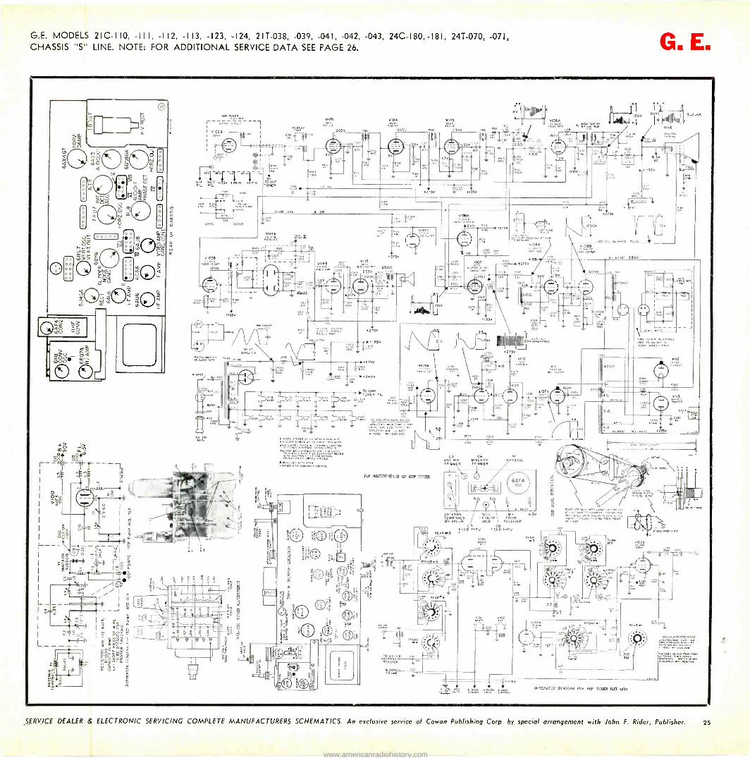
G.E. MODELS 21 C-1 10, -III , -112, -113, -123, -124, 2 I T-038, -039, -041, -042, -043, 24C-180, -181, 24T-070, -071, CHASSIS 1151 LINE. NOTE: FOR ADDITIONAL SERVICE DATA SEE PAGE 26. G. E.
00
tJ
/
3.
Ñ a Ó_á
I- ä
CUl x r '...;co g
}
Li
D
(cc 0007
00 00 00 `r
© L1-2$ Q0 [DU
Wï SZ DO
A
ZZ
Cl.
XON ml. WOO
©
r °ur.°, ., °u, ' 1 VVI0028
1l.e-4- -1 O I
91-
UHF SOT. A33
tT " 0235V .240V ,51 ro NF FIL FIL TUNER
Lwx 130
00.d1
vIm .F. t
265V
VIOa V106
1152 s«o 250V
36
+2 5v
Fn
V106A
+1oca cHa r7
90V
2
06,
5-3-55
2.6
41 5V
V117
er a«r 1[,1 .,.«, : .
1.600 EC
VII4A
(U0=1
14.
M Y
52 e$
óSwi
61.8 641'1 M
75v V115
Mss*^' 6500
,
22005VV1+ , tt mw /\ 1 yo,
iiÓ 135V
Zile°
TO UHF
aw
ill T 4áo
oLD
[t- -
I Ito fF I IFmcE
-fg
60,
10
V1065
2 °A24V
' 275V 51 r+w
2012
21V
V109A
.3
VIVI T 4
23
210V
vsvsRM TISE
. WOK cAAKIA.se LESS ',Let
9v
TOP ADJUSTMENTS D)[ UM. TUNER
REAR
60V ÌA
225V
L -f l-r )V
AK
e. R
[.;w VI
+-2130
oRle
42V
.5 v
21 56
1200V
,__T 100
óF 1w,
+275v
/ I.ob ;rlY
6.3V AC
5-135V
.15v°
32V
e. ecos! 530V
118V
ig%
ron leurrV
A'3Tv
m1i
500V
0.66. vocALs arc
1230
160V 65
C3 CH ANT MI%ERR-E TRIMMER TRIMMER
OPYnSi>L
ANTENNA 500 8+ 6 TERMINALS I -F OUTR FROM ON SALON JACK RECEIVER
FEED THRU FEE) THRU
REAR224
1appE.6 ,x,
°ñivs*ó °O I
V101 .
1'2a. a2
SI
g
4200
510
22n N.
301
4 0 e.e001T *MIT( 2215V
v112
2200
V1I3
reel
0'
'S,
EAR
_ V ...., w. yÇ vie, ia2ex. SCIEMATIC DIAGRAM POR VF82 TUfdII1 R./E-050
<63 /cot,
.1lxo
SERVICE DEALER & ELECTRONIC SERVICING COMPLETE MANUFACTURERS SCHEMATICS. An exclusive service of Cowan Publishing Corp. by special arrangement with John F. Rider, Publisher. 25
www.americanradiohistory.com
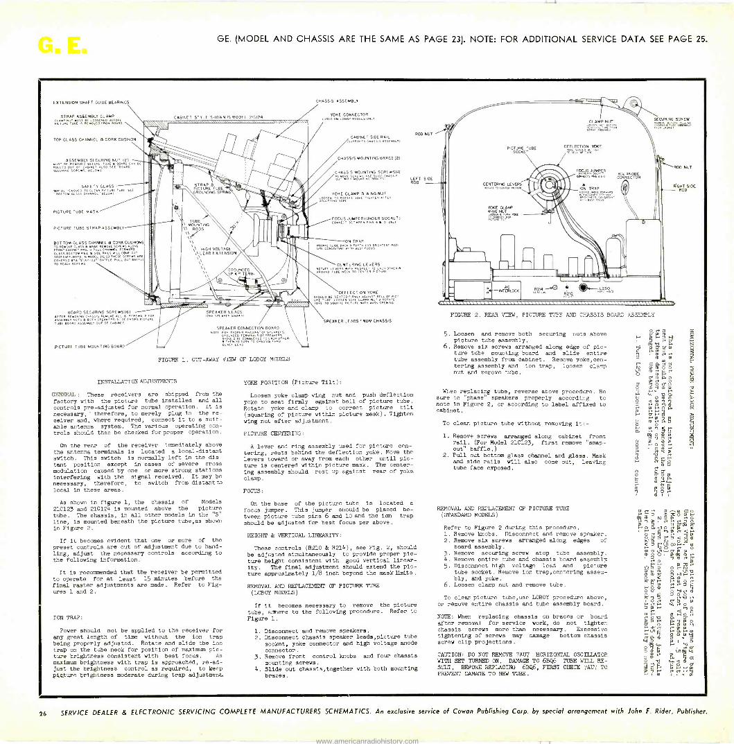
GE. (MODEL AND CHASSIS ARE THE SAME AS PAGE 23). NOTE: FOR ADDITIONAL SERVICE DATA SEE PAGE 25.
EXTENSION SHAFT GUIDE BEARINGS
STRAP ASBEMBLY CLAMP
vlcf u( TURC iS ÁINOy(O (PUR BÓ5(0
`OP GLASS CHANNEL B CORK CUSHION
ASSEMBLY SECURING NUT 121 MUST BE REMOVED ORE TUBS B BeiRq CAN B
LEO'WOREPLIL OUT 0 CABINET ALSO E[' OA 0
SECURING SCRE NS;) BELOVI
SAFETY GLASS . REMOVED TO CLEAN PN OVRE TUBE SCE BO « ON GLASS CHANNEL: L I
PICTURE TUBE MASK
PICTURE TUBE STRAP ASSEMBLY
BOT TOM GLASS CHANNEL B CORK CUSWONS TO REMOVE GLASS B Id...REMOVE SCREWS ALONG IRONT CABINET BAIL B PULL CHANNEL FORMARD 6L ASS,BOT TOM RAIL B SIDE RAILS NHL COME OUT
TOGE)NER NOTE,IN MODEL SK123 THESE SCRENS ARE
COVERED BTSNAP OUT BAFFLE RVLL OUT BAFF LE
TO REACH SCREWS
BOARD SECURING SCREWSI61 AFTER REMOVING CHASSIS...OFF ALL 6 SCREWS, Toe. ASSEMBLY NUTS B BOTH SAE AKERS SLIDE ENTIRE PICTURE TUB[ BOARD ASSEMBLY OUT 06 CABINET.
PICTURE TUBE MOUNTING BOARD
CABINET STYLE 5H0 N IS MODEL 210124
ASKON.M.M.IWWQMVP.WIMOLS,%v
STRAP B PICTURE TUBE GROUNDING SPRING
TUBE MOUNTING
\\ RODS \\e.''
\\ HIGH VOLTAGE \\\LEAD EXTENSION
\\
SPEAKER LEADS IONE SPEAKER SFORNI
SPEAKER CONNECTION BOARD NOTE FOR PROPER PHASING' Of SPEAKERS,
GROUNDED TERMINALS OF SPEAKERS SHié g ñI ÚÑN" Ç'C ssEOSEKnRO'HER, BLACK LEAD
FIGURE 1. CUT -AWAY VIEW OF LOBOY MODELS
INSTALLATION ADJUSTMENTS
GENERAL: These receivers are shipped from the
factory with the picture tube installed and all
controls pre -adjusted for normal operation. It is
necessary,' therefore, to merely plug in the re-
ceiver and, where required, connect it to a suit-
able antenna system. The various operating con-
trols should then be checked for proper operation.
On the rear of the receiver immediately above the antenna terminals is located a local -distant
switch. This switch is normally left in the dis-
tant position except in cases of severe cross
modulation caused by one or more strong stations interfering with the signal received. It may be necessary, therefore, to switch from distant to
local in these areas.
As shown in figure 1, the chassis of Models
21C123 and 210124 is mounted above the picture
tube. The chassis, in all other models in the "S"
line, is mounted beneath the picture tube,as shown
in Figure 2.
If it becomes evident that one or more of the
preset controls are out of adjustment due to hand-
ling, adjust the necessary controls according to
the following information.
It is recommended that the receiver be permitted to operate for at least 15 minutes before the
final raster adjustments are made. Refer to Fig- ures 1 and 2.
ION TRAP:
Power should not be applied to the receiver for any great length of time without the ion trap being properly adjusted. Rotate and slide the ion trap on the tube neck for position of maximum pic- ture brightness consistent with best focus. As
maximum brightness with trap is approached, re -ad- just the brightness control as required, to keep picture brightness moderate during trap adjustment.
CHASSIS ASSEMBLY
YOKE CONNECTOR USED ON LOBO. MODELS ONLY)
CABINET SIDE RAIL SURPORTS CHASSIS ASSEMBLTI
CHASSIS MOUNTING BRACE 12)
CHASSIS MOUNTING SCREWSI4)
OUTD:1,0 00Ii"N.,ASAO000CISCHASS1' LEFT SIDE ROD
YOKE CLAMP B WING NUT LOOSEN TOR YOKE TIG HTEN AF TIR A Oyu STING TOM[ '
FOCUS JUMPERIUNDER SOCKET) NAAuT BETWEEN PINS 6 B O ONLY
ION TRAP ROTATE,SLelf BACK B FORTH FOR BRIGHTEST Plt i UR( CONSISTANT WITH BEST fOLUS
CENTERING LEVERS
AñEAxD ETE B[R[S.Efn H
x [[RiET 'vIC T URlOt
HER B
DEFLECTION YOKE sNOVLD BE SEATED FIRMLY AGAINST BELL Of INCr URE E OSEx V ATE rOKE TO ESOUARE RICTUR[ WITH MASK OPE xIN4
SPEAKER LEADS FROM CHASSIS
YOKE POSITION (Picture Tilt):
Loosen yoke clamp wing nut and push deflection yoke to seat firmly against bell of picture tube. Rotate yoke and clamp to correct picture tilt
(squaring of picture within picture mask). Tighten
wing nut after adjustment.
PICTURE CENTERING:
A lever and ring assembly used for picture cen-
tering, rests behind the deflection yoke. Move the levers toward or away from each other until pic-
ture is centered within picture mask. The center- ing assembly should rest up against rear of yoke
clamp.
FOCUS:
On the base of the picture tube is located a
focus jumper. This jumper should be placed be-
tween picture tube pins 6 and 10 and the ion trap
should be adjusted for best focus per above.
HEIGHT & VERTICAL LINEARITY:
These controls (R210 & R214), see Fig. 2, should
be adjusted simultaneously to provide proper pic-
ture height consistent with good vertical linear- ity. The final adjustment should extend the pic- ture approximately 1/8 inch beyond the mask Emits.
REMOVAL AND REPLACEMENT OF PICTURE TUBE (LOBOY MODELS)
If it becomes necessary to remove the picture
tube, adhere to the following procedure. Refer to
Figure 1.
1. Disconnect and remove speakers. 2. Disconnect chassis speaker leads,picture tube
socket, yoke connector and high voltage anode
connector. 3. Remove front control knobs and four chassis
mounting screws. 4. Slide out chassis,together with both mounting
braces.
CLAMP NUT
DEFLECTION YOKE
m
SECURING SCREW
FIGURE 2. REAR VIEW, PICTURE TUBE AND CHASSIS BOARD ASSEMBLY
5. Loosen and remove both securing nuts above picture tube assembly.
6. Remove six screws arranged along edge of pic- ture tube mounting board and slide entire -
tube assembly from cabinet. Remove yoke,cen- tering assembly and ion trap, loosen clamp nut and remove tube.
When replacing tube, reverse above procedure. Be sure to "phase" speakers properly according to note in Figure 2, or according to label affixed to cabinet.
To clean picture tube without removing it: -
1. Remove screws arranged along cabinet front rail. (For Model 21C123, first remove "snap - out" baffle.)
2. Pull out bottom glass channel and glass. Mask and side rails mill also come out, leaving tube face exposed.
REMOVAL AND REPLACEMENT OF PICTURE TUBE (STANDARD MODELS)
Refer to Figure 2 during this procedure. 1. Remove knobs. Disconnect and remove speaker. 2. Remove six screws arranged along edges of
board assembly. 3. Remove securing screw atop tube assembly. 4. Remove entire tube and chassis board assembly 5. Disconnect high voltage lead and picture
tube socket. Remove ion trap,centering assem- bly, and yoke.
6. Loosen clamp nut and remove tube.
To clean picture tube,use LOBOY procedure above, or remove entire chassis and tube assembly board.
NOTE: When replacing chassis on braces or board after removal for service work, do not tighten chassis screws more than necessary. Excessive tightening of screws may damage bottom chassis screw clip projections.
CAUTION: DO NOT REMOVE 7AÚ7 HORIZONTAL OSCILLATOR WITH SET TURNED ON. DAMAGE TO 68Q6 TUBE WILL RE- SULT. BEFORE REPLACING 6BQ6, FIRST CHECK 7AU7 TO PREVENT DAMAGE TO NEW TUBE.
G co? Syli 0 rCN p
5N H E* 6 I I
26 SERVICE DEALER & ELECTRONIC SERVICING COMPLETE MANUFACTURERS SCHEMATICS. An exclusive service of Cowan Publishing Corp. by special arrangement with John F. Rider, Publisher.
www.americanradiohistory.com

SOUTH RIVER CHIMNEY MOUNTS
In keeping with South River Metal Products Co.'s policy of manufacturing products that permit max- imum safety when working in precarious positions, they have recently redesigned the entire SNAP -IN line of chimney mounts and wall brackets. A spe- cially designed "U" bolt is now used with all SNAP - IN antenna mountings which permits one hand spintite fastening. The installer inserts the special U bolts instead of the customary nuts and screws.
(Check 816 on inquiry card for more information)
R -COLUMBIA COUPLER
In line with the trend to "do-it-yourself" depart- ments in radio and television stores, R -Columbia Products Co. Inc., has developed a new two set coupler that can be sold by the Service Dealer. Available in three models, HK I for normal signal gain with normal interference rejection; HK 2 for exceptional signal gain with normal interference rejection; HK 3 for maximum interference rejec- tion with normal signal gain. It can be installed on the antenna mast.
(Check 818 on inquiry card for more information)
TACO TRAPPERS
Technical Appliance Corporation, in announcing their new Stay -Lok assembly, stated that Taco Trappers and Super Trappers were now available to the trade in two designs. The original models employing the tension booster design are continued in the line, being supplemented by Models 2880, 2885 and 2890 which utilize the new element de- sign. With these new models elements are auto- matically locked in without using any tools.
Check 811 on inquiry card for more information)
JERSEY SPECIALTY COLORED WIRE
Jersey Specialty has announced to the trade that they are now in production on all colors -300 ohm twin lead television wire (red -white -blue -green - pink -yellow -gold -silver -brown -clear). Installers can now match the outside color paint on homes or can match woodwork, wallpaper or even the rug on the floor. It even brightens the appearance of the room in place of the usual brown twinex. The color price is the same as for the brown twinex.
(Check 814 on inquiry card for more information)
BAKER "YUG"
A new 5' tower has been announced by the Baker Manufacturing Co., as an answer to the dealer's desire to eliminate guy wires on antenna installa- tions up to 20' above the roof. It resembles, but is
much larger than the successful 3' tower introduced previously which permits antenna mountings up to 12' without guys. Both towers are now nicknamed YUGS, a letter reversal of the word guy. The ab- sence of guys means safer, faster roof installations.
(Check 815 on inquiry card for more information)
SERVICE DEALER
NEW ANTENNAS
Irlef
meré Bun=
'i'StI TENN< de -luxe
TRI -SET COUPLER
DYNAMIC ELECTRONICS
'MTfxMA , MMRIMOSVIs
ATTENUATOR: miìríé [AitT11116
CHANNEL MASTER FILTER
Introduction of a completely re -designed model of its UHF -VHF inter -action filter, the "Ultra -Tie," has been announced by Channel Master Corp. The filter joins together VHF and UHF antennas of all types for use with a single transmission line to the set. The "New Ultra -Tie" performs this function with leads of any length. Transmission wires be- tween the two antennas and the filter need not be cut to a specifically prescribed measurement.
(Check 817 on inquiry card for more information)
TELCO ANTENNA
"Switch-O-Matic" is the name of a new high gain indoor TV antenna just developed by Telco Elec- tronics Mfg. Co. It's a refinement on the basic "rabbit ears" style and said to provide new sensi- tivity on all viewing channels from 2 to 83. The "Telco Golden Switch-O-Matic" has two features that give it unusual power-six-phase tuning and a slide adjustment. The six -phase switch on the antenna's base provides improi-ed reception.
(Check 813 on inquiry card for more information)
DYNAMIC ELECTRONICS ACCESSORIES
Dynamic Electronic's complete new line of acces-
sories in the tentenna series for fun -uhf, vhf and color TV are to be sold through electronic parts jobbers and distributors as service aids to improve reception where problems exist even when the re-
ceiver is operating to the accepted standards of its manufacturer. In such cases reception can be im- proved by using a properly designed accessory.
(Check 812 on inquiry card for more information)
WELCO ZEE -X
The Welco Mfg. Co., of Burlington, Iowa, has recently presented the Zee -X Model Z-4 television antenna which is said to exhibit exceptional low and high band antenna response patterns. Welco's arrangement of its exclusive Zee -X elements offers an efficient Direction System-full half -wave direc- tor action on both VHF bands, the low channels up to 6 and the high channels from 7 to 13. This per- mits excellent VHF reception.
(Check 819 on inquiry card for more information)
SERVICE DEALER and ELECTRONIC SERVICING AUGUST, 1956 27
www.americanradiohistory.com

VIDEO
DET.
1st. VIDEO AMP.
(A) S ngle detector block diagram
I.F LUMIN-
ANCE DET.
SOUND 1
LUMINANCE AND H AND
V SYNC
CHROMA (ALSO BURST)
LUMINANCE AND H
AND V SYNC
SOUND a CHROMA
DET
SOUND
CHROMA (ALSO BURST)
(B) Dual detector block diagram; Luminance signal detected
separately
I.F LUMIN- ANCE AND
CHROMA Er -
J SOUND
LUMINANCE ALSO H AND
V SYNC )
CHROMA (ALSO BURST)
(C) Dual detector block diagram; Sound signal detected
separately
Fig. 1-Block diagrams of various
types of color detector circuits.
FIVE different signals are contained in the composite video signal pre-
sented to the video detection circuit. These signals are the chroma, lumi- nance, color burst, sound, and hori-
Discussion and analysis of the various types of detectors used in color TV
receivers. Several circuits are illustrated.
COLOR DETECTORS
zontal and vertical sync signals. If we
were to consider the horizontal and vertical sync signals separately we would have six signals. These signals have the frequency ranges shown below.
Signal Takeoff Systems
Three signal takeoff systems are em-
ployed for extracting the individual sig-
nals listed above. These systems are
shown in rather simple block diagram form in Fig. 1 and were introduced to
the reader originally at the beginning of this chapter (see May Service Dealer & Electronic Servicing Pg. 16). Refer-
ring to Fig. 1:
Signal Center Frequency
Upper Limit
Lower Limit
Chroma 3.58 mc 4.08 mc 2.08 mc* or 3.08 mc
Luminance - 3.2 mc** 0
Color Burst 3.579545 mc*** - - Sound 4.5 mc 4.5 mc + 25 kc 4.5 mc - 25 kc
Horizontal 15,734 cps - - Sync Pulse Vertical 59.94 cps - - Sync Pulse
*For I/Q receivers the lower limit is 2.08 mc., and for R-Y/B-Y receivers the lower limit is 3.08 inc.
**The response at the higher frequencies falls off considerably as compared to
the lower video frequencies. The luminance signal must be sufficiently at- tenuated at 3.58 mc. to reduce dot pattern and the resultant moiré effect.
***Consists of 8 to 11 cycles on the back porch of each horizontal sync pulse.
by BOB DARGAN and SAM MARSHALL
From a forthcoming book entitled
"Fundamentals of Color Television"
Figure 1 (A) shows a block diagram of a Single Video Detector type where the entire composite video if signal is
demodulated in a single detector. The output of this detector feeds the first video amplifier tube following which the various signals are processed in succeeding circuits.
Figure 1 (B) shows a block diagram of a Dual Detector type where the luminance signal is demodulated in one detector and the combined sound and chroma signals are demodulated in another detector.
Figure 1 (C) shows a block diagram of a Dual Detector type where the combined luminance and chroma sig- nals are demodulated in one detector, and the sound signal .n another de- tector.
It will be observed, from a study of Fig. 1, that in all cases the color burst signal is fed along with the chroma signal following detection. In subse- quent circuits these two signals are separated from each other. It will also be observed that following detection, the sync signal which contains the hori-
3rd. PIX
LE AMP
-I-
12,H Qo
12K
120
(
-20 V
2nd DET
COLOR TAKE-OFF TRANSE.
1st. VIDEO AMP
l
ÿ
BANDPASS --AMPLIFIER
8+
TO BURST KEYER
t.8 K 250pH 5K
18K
TO 1st SOUND I F TRANSE.
B+ SOUND
TO HOR.
DELAY LINE
AND VERT SYNC AMP
TO LUMINANCE AMPLIFIER
BURST
CHROMA
ro DEMODULATOO
DRIVER
H AND V SYNC
Fig. 2-Partial schematic of receiver video I.F. signal. Separation of the
employing selective circuits
using a single detector for tie composite various component signals is effected by as shown in the above diagram.
28 SERVICE DEALER and ELECTRONIC SERVICING AUGUST, 1956
www.americanradiohistory.com

zontal and vertical sync information is
fed along with the luminance signal.
These two sets of signals are duly processed in subsequent circuits wher- ever separation is required.
Single Detector Analysis
In Fig. 2 we observe a simplified partial schematic of the RCA 21CT661-4 color TV receiver showing how the signal from the 3rd pix if is fed into the crystal 2nd detector. The demodu- lated output of this detector is then fed into a video amplifier tube where the process of extracting the various signals enumerated above are begun.
Notice that the luminance signal is
taken off the cathode circuit of the video amplifier. The chroma signal is
taken off the secondary of a Color - Takeoff transformer. The opposite end of the primary of this transformer, which is maintained at an rf potential above ground by a 5K resistor, provides the take-off point for the sound and sync (horizontal and vertical) signals. Separation of the sync signals from the sound signal is effected by means of a
tuned 1st if sound transformer. The sound signal is subsequently removed from the sync signals in the sync ampli- fier circuits.
Dual Detector -Separate Luminance
Detector Analysis
A circuit employing dual -detection in which one of the detectors is used for luminance and the other for chroma and sound is shown in Fig. 3 which is
a partial schematic of the Emerson Model C502A color receiver. Notice that the plate of the 4th if tube feeds parallel signals to T-7 and T-6. T-7 is a trans- former which picks off the if signal preparatory to demodulation of the signal by crystal XTAL-2, the lumi- nance detector. The output of this de- testor provides the signals for the lumi- nance section as well as the horizontal and vertical sync amplifier.
In T-6 we observe a transformer which provides the sound takeoff sig- nal across terminal No. 3 and ground. The tap on the transformer (terminal No. 5) connects through a 6.8K resistor and a 3K control for variable sound rejection of the system. From terminal No. 2 we obtain the chroma signal
Video speed Servicing Systems Vol. 2
is now available
VIDEO SPEED SERVICING
SYSTEMS
Simplifies Servicing All Television Receivers
SERVICE DEALER
VOLUME 2
Volume 2 of VSSS is completely new and does not
cover any of the items published in volume 1.
Volume 2 of VSSS contains most of the data sheets
published since May 1953 plus several hundred
new data sheets that have not been published here-
tofore and which will not be published anywhere
else.
Although published as a hard paper cover bound
volume each page in VSSS Vol. 2 is marked so
the pages can be inserted into a loose leaf ring
binder or into our VSSS Vol. 1 cloth -covered ring -
binder edition.
VOL. 1 and VOL. 2 VSSS Paper Bound Editions
$2.95 Postpaid.
Vol. 1 Ring -Binder Edition $4.95 Postpaid.
Each edition of Video Speed Servicing Systems is
guaranteed to simplify servicing all TV sets. Each
edition contains over 600 service items covering the most -serviced TV models now in use. All lead-
ing manufacturers' lines and models are covered.
The VSSS data sheet for any particular TV set
maker's model or chassis number gives: 1-the sec-
tion of the set affected: 2-the symptom; 3-the cause of complaint; 4-the solution.
Order Your Copy Today
.UT OUT AND MAIN
VIDEO SPEED SERVICING
SYSTEMS
Simplifies Servicing All Television Receivers
COWAN PUBLISHING CORP., 67 WEST 44TH STREET, NEW YORK 36, N. Y.
Please send me postpaid Video speed Servicing Systems Vol. 1 in Paper Bound Edition for $2.95
" Vol. 1 in Hard Cover Ring -Binder Edition for $4.95
" Vol. 2 in Paper Bound Edition for $2.95
My Check for $ is enclosed. (If you reside in New York City add 3% to cover city sales tax.)
VOLUME 1
Name
Address
City Zone State
J
SERVICE DEALER and ELECTRONIC SERVICING AUGUST, 1956 29
www.americanradiohistory.com

What About Color TV? There has been much talk about Color TV - and about whether or not available TV equip- ment is suitable for Color TV reception. Whatever other conditions prevail-one thing is certain .. .
ALL TAB TV PRODUCTS ARE ENGINEERED for COLOR
Every piece of Blonder -Tongue equipment ever built, sold and in use - or ever to be used - is designed with color in mind . . . with the flat, broad output required for color.
these products include
DISTRIBUTION AMPLIFIERS CONVERTERS
SIGNAL AMPLIFIERS
LINE AMPLIFIERS
BOOSTERS
irm
MIXER AMPLIFIERS
! i . and all B -T impedance matching devices, equal-
izers, couplers, attenuators, connectors and tap -offs.
For example:
The
2 -SET COUPLER Model TV -42
is the only type approved by engineers for color -with a flat response from 0 to 900 mc.
Every ® Master TV System now in opera- tion is designed to meet the exacting demands of Color Television ... today and tomorrow.
Keep abreast of the Latest Developments. Apply for your FREE subscription to the B -T BULLETIN.
t ;
Write today, to Dept. OH -7
BLONDER -TONGUE LABS., INC. Westfield, New Jersey In Canada: Telequipment, London, Ontario
The largest manufacturer of TV Signal Amplifiers, UHF Converters and Master TV Distribution Systems,
4th. VIDEO I.F. r
T7
i XTAL-1
T6
L
111
5.6 pH
10
- L2
L J
6.8 K
XTAL-2 -
11, 5.6 200 pH pH
'-8.2 J
2.2
3K SOUND REJ.
47NP0 i = I
_
H j
J
10
TO SOUND I.F. SECTION.
DELAY LINE
11
>I CHROMA
AMP.
LUMINANCE SIGNAL
LUMIN ANCE AMP
TO
H AND V
SYNC AMP.
H BURST SEP.
CHROMA TO
DEMODULATOR
TO 3.58 hIC.
A PC
Fig. 3-Partial schematic of a dual detector receiver. The luminance signal is
detected separately in one of the detectors. The sound and chrominance signals are detected together in another detector as shown above.
which is fed into the chroma section for further processing.
In the CBS -Columbia 205 receiver the video detector and signal takeoff circuit, as shown in Fig. 4, provides a
separate crystal detector for the sound signal, and another for the chroma and luminance signals. Here we ob- serve that the video if signal from the plate circuit of the 5th video if ampli-
fier is divided into two paths. One path feeds the sound detector as shown, coil L9 being tuned to 4.5 rnc.
In the other branch of the detected signal the video if signal is sent through a sound trap of the "Sound Reject" type described in the May 1956 issue of Service Dealer and Electronic Servicing on page 32. The video if information comprising the chroma and luminance
SOUND DETECTOR TO 1st. SOUND I.F. GRID
111
C13 CI 41.25 MC.
tee
SOUND
C12
CHROMA AND LUMINANCE DETECTOR
FROM 5th.I.F
AMP PLATE /"4 1-.075-/"4
C2 C3 L2
R1
C5 R2
R3
500 SOUND REJECT
111
L3
C4
1st VIDEO AMP. Q
C13 '8 /WWr
TO HOP. AND VERT SYNC AMP
3.58 MC. SYNC
L6
g L4
R4 4.7K
R5
8+150V 4.5 MC.
IN* C10-
b C7 L5 (=>
C8
R6 R7 . <
CONTRAST
B+ 300 V.
L7
I --HUE
BURST
LUMINANCE
C9 R10
LUMIN- ANCE AMP
TO BURST AMP.
1 C11
TCHROMA AND LUMINANCE
TO BAND- PASS AMP.
CHROMA
Fig. 4-Partial schematic of a color receiver using a separate detector for the sound signal and another detector for the chroma and luminance.
30 SERVICE DEALER and ELECTRONIC SERVICING AUGUST, 1956
www.americanradiohistory.com

signals are demodulated together and fed into a video amplifier. The output of the latter provides three divisions of
the detected signal. These diivisions
take place as follows: The chroma signal is taken off at the
cathode. Here a 4.5 mc trap provides further sound attenuation and the sig-
nal is sent into the bandpass amplifier via a contrast control. The bandpass amplifier which is tuned between 2.08
inc and 4.08 mc serves to attenuate the
useful luminance signal, passing only the chroma information.
The plate circuit of the video ampli- fier feeds the video signal across L6 and C9 which is a parallel resonant circuit tuned to 3.58 mc. Because of its parallel resonant nature at 3.58 mc the color
burst signal develops a high voltage at
point A and is forced through C13 to
the Burst Amplifier where it is proc-
essed as described in previous install- ments.
Signal frequencies other than 3.58
mc, of which the luminance and sync
signals are examples, find an easy path through L6 and C9 and are transferred on to point B. At point B the signal divides again, making its way into the luminance amplifier and into the hori- zontal and vertical sync amplifiers where appropriate signal processing extracts the desired signal.
Summary
Extraction of the various signals con- tained in the composite video if signal takes place in the section of the color receiver immediately preceding or im- mediately following detection.
Three detection systems are generally to be found. These consist of a single detector for all of the component sig-
nals; a dual detector in which one de-
tector demodulates the sound if and the other the chroma and luminance if signals; and a dual detector in which one detector demodulates the luminance if signal and the other the chroma and sound if signals.
Methods used to separate one signal from another where they appear in a
common circuit is generally accom- plished by means of tuned coils or transformers which accept the desired signal and reject the undesired signal.
Together we can give 'ern the knockout blow!
PH I LCO Last year Philco sponsored the industry's first Tube Racket -Smashing Campaign. The results . . won- derful cooperation from service dealers and praise from thousands of TV and radio owners who had been "taken over" on replacements.
Now, after one year of slugging, the tube racket- eers are staggering ... and we're ready to "knock 'em out" with another great Tube Racket-Smash-
PHILCO TUBES IMPROVE THE
PERFORMANCE OF ANY TV OR
RADIO RECEIVER
ing Campaign. During the month of August, Philco Distributors will credit you with 5c for old, worn out tubes you bring in, toward the purchase of new Philco receiving tubes. Your old tubes will be smashed right before your eyes. Join the Tube Racket -Smashing Campaign today . . . for the good of the industry ... for extra profits for you.
See your Philco Distributor.
PHILCO CORPORATION ACCESSORY DIVISION
PHILADELPHIA 34, PENNA.
ii7PH L CO) 411 QUALITY 6a CU ,ZiJEL
SERVICE DEALER and ELECTRONIC SERVICING AUGUST, 1956 31
www.americanradiohistory.com

it a d e A plaque honoring Ray R. Simpson's "leadership
and inspiration" during his 50 years in the electronic instrument field was presented to the Chicago in- dustrialist recently.
The presentation was made at a dinner sponsored by sales representatives of Simpson Electric Company, Chicago, founded by Simpson. The 35 -pound copper and wood plaque was presented by John M. Forshay of New York City on behalf of the 100 sales repre- sentatives attending the affair at the Congress Hotel.
An unprecedented contract between General Elec- tric Cornpanys' Communication Equipment Section and Ryder System, Inc., one of the country's largest transport firms, calling for the widespread leasing of mobile radio units as regular trucking gear, was an- nounced jointly by the two companies. Under the unique agreement, General Electric will lease two- way radio units for installation in trucks owned by Ryder Truck Rental Systems, a subsidiary of Ryder System. Ryder Truck Rental in turn will offer radio - controlled pickup and delivery to customers obtaining transport equipment from the Ryder organization on a lease basis.
The Washington County, Maryland Board of Education, with headquarters here, announced plans for installing the nation's first large scale closed- circuit television institutional program throughout an entire public school system.
Superintendent of Schools. William M. Brish, dis- closed that the program will be instituted when school opens in September, with more than 6,000 pupils in two high schools and six elementary schools receiving an important part of their daily instruction by television. Present plans call for the extension of the program to the entire Washington
County school system by September 1958, with all 47 schools supplied with closed-circuit equipment and approximately 20,000 benefitted from direct in- struction by television.
Under the plan outlined by Mr. Brish all neces- sary equipments for school installations during the life of the project, presently planned for five years, will be contributed by the nation's leading elec- tronic manufacturers through their official trade association, the Radio -Electronics -Television Manu- facturers Association (RETMA). Funds to provide for the training of personnel and for supervising the program will be granted by the Fund for the Ad- vancement of Education, an independent agency established by the Ford Foundation.
DOUGLAS H. CARPENTER, formerly chief en- gineer of JFD Mfg. Co. Inc., Brooklyn, New York, announces the opening of offices at 19 West 44th Street, New York City. Mr. Carpenter's firm will deal with various organizations in the electronic and electro mechanical industries on a consulting basis, in addi- tion to public relations work in association with an- other New York organization.
The Hickok Electrical Instrument Company an- nounces the opening of a new San Francisco Branch at 2585 Shattuck Avenue in Berkeley, California. George Ksander, Sales Engineer with Hickok for 10
years, has been appointed West Coast Manager for Hickok's complete line of electrical and electronic test equipment and electrical indicating instruments.
A 25th anniversary celebration in honor of the Snyder Mfg. Co., makers of auto radio and TV an- tennas and automobile accessories, will be held in the Beverley Hilton Hotel in Los Angeles. Key West Coast Snyder distributors will pay tribute to Ben and Gus Snyder, founders of the company. A sup- per party will be followed by an advance showing of all Snyder fall lines in the Presidential Suite of the hotel.
A new engineering development program has been added by Raytheon Manufacturing Company to encourage its employees to advance profession- ally by attending evening college classes and obtain- ing scientific training to qualify them for engineer- ing positions. The program begins this fall.
Participants will be granted tuition, fees, and a
stipend for books for study at accredited colleges and universities with evening divisions, such as Boston University and Northeastern University. Grants will be made on a yearly basis, renewable for a second year.
Dan Johns, Moses Radio -Electronics Co., Hartford, Conn.; William Osterhaut, Bob's Electric Co., Win- sted, Conn.; John Hurchala, Staf}ord Electric Co., Sta fiord Springs, Conn.; Robert Kelly, Radio Service Laboratory, Hartford, and Dennis Dandara, Bob's Electric Co., are shown receiving pointers from Herbert Evander, Tung -Sol Electric Inc. commercial
engineer, during groups' recent trip to three Tung -Sol tube plants in Newark, N. J. Mr. Johns escorted the four winners of the Moses Co. bonus plan contest. The one -day trip included an hour-long session with Louis Rieben, Tung -Sol president.
According to the Radio & TV Guild of Long Island News, the Detroit City Council passed unanimously an ordinance requiring a license to conduct a busi- ness of installing and servicing television equipment. The ordinance is aimed at "irresponsible sales meth- ods," "inferior installation, maintenance, and re- pairs."
[Continued on page 12]
32 SERVICE DEALER and ELECTRONIC SERVICING AUGUST, 1956
www.americanradiohistory.com
GUEST [Pon p. 19]
EDITORIAL
time and a higher quality of service work. When a new or unfamiliar re-
ceiver comes into your shop, stop for a
few minutes before you begin to service the set. Take out the manufacturer's service information on the set. Study the overall circuitry of the receiver. If there are any new or unusual circuits, read the circuit description of that por- tion of the receiver. Glance through the scope wave forms illustrated and note from where they are taken. Ob- serve any special notations as to voltage readings, alignment or servicing pro- cedures. All this takes but a very few minutes out of each day and will reward the service technician with a full work- ing knowledge of every receiver he may be called upon to service. In turn, he is
then in position to provide his custom- ers with the most complete, most com- petent and highest quality service avail- able.
To supplement this self-improvement program of the service technician, most major Radio & Television Manufactur- ers have made available to the service profession: training courses, schools. home study material, and monthly tech- nical publications. Avail yourself of these opportunities to broaden your edu- cation for, as with any other major profession, you must continually strive to increase your technical knowledge and improve your servicing ability.
1--
D 0 , I
Just.$a
ca,acitor s
sForSptae 8YCa+o1o9Nemb
e C
Know what you're
gettinget
excels/ *that
you ant.n+t gue .gison
Sprague
e Use complete
service catalog
C-610.
Sprague Products
Company,
11 MorshQ Street,
North doms,
A setts. R
MasS°`hU
WORLD'S LARGEST CAPACITOR MANUFACTURER
Radio - TV Hi Fi -Audio
SERVICEMEN Communications Electronics
SIVÌCE DEALER and ELECTRONIC SERVICING
is YOUR magazine.
Subscribe to it now. Reap its benefits! Now every serviceman engaged in every phase of radio -TV
and Industrial Electronics servicing will find:
SUBSCRIPTION RATES: 12 Issues $3; 24 Issues $5 (In the U.S.A., U.S. Possessions, Canada and Mexico). Elsewhere add $1 per year.
COWAN PUBLISHING CORP.
67 W. 44 St., New York 26, N.Y.
Sirs: I remit herewith $ as follows:
Name
Address
NEW RENEWAL
Enter a subscription for years
City
Name of firm
Firm's business address
City
Zone State
Zone _ State
CHECK YOUR CLASSIFICATION
Independent Radio-TV Serviceman D Owner
Radio-TV Service Organization Employee
Retail Store having Service Department D Service Mgr.
D Industrial Electronic Service Firm D Student
Firm having electronic equipment which I service and maintain
If some other type cf company describe
A TYPICAL ISSUE COVERS
Latest TV Installation and Maintenance Techniques for VHF and UHF
Auto Radio Installation and Service
Mobile Communications, 2 -Way Radio, Ship -to -Shore Radio Installation and Serv- ice Techniques
Industrial Electronics Equipment Servicing Data
Advanced Data on New Circuitry
Production Changes and Field Service Data on Receivers
New Tubes
New Test Equipment, Operation and Application Data
P.A. Installation and Service
Hi-Fi Installation and Service
New Developments, Such As Transistors, Color, UHF, etc.
News of the Trade
Service Short Cuts and Shop Notes
Explanation of Difficult Circuits
M'fgr's Complete Line of TV Schematics
Video Speed Servicing Systems
SERVICE DEALER and ELECTRONIC SERVICING AUGUST, 1956 33
www.americanradiohistory.com

PHAOSTRON
PROBE -LITE ILLUMINATED TEST PROBE
SELF-CONTAINED SEE WHAT YOU ARE TESTING!
It is just like having an extra hand. Simply insert the probe from your tester into the jack of the Probe -lite and the Probe -lite becomes alive to instantly give you a brilliant, pre -focus spot- light on the area that you are testing plus a long, extra slender, probe tip for making electrical contact in difficult places which previously were inaccessible. It could pay for itself the first time you use it.
GET A FREE PROBE -LITE If you are the fortunate owner of a Phaostron "555" or "555A" VOM, we will send you a Probe - lite free. Mail us the warranty page you will find in your instruc- tion manual. We will send you a new Probe -lite and return your warranty. Be sure you include your correct name and address. This offer is good until October 1,1956.
PHAOSTRON INSTRUMENT & ELECTRONIC CO., 151 Pasadena Avenue, South Pasadena, Calif.
THE WORK BENCH Unusual Service Problems And Their Solutions
by PAUL GOLDBERG Service Manager
THIS month's installment concerns problems in color receivers. A
knowledge of color receiver theory and circuity is necessary in solving these problems. This article has been written with the hope that the reader has been reading the very informative articles on color by Dargan and Marshall in this magazine.
CBS Color Chassis 205 The receiver was turned on and it
was noted that the black and white pic- ture was normal; however, during color transmission there was an absence of red and the picture seemed to be dom- inated by the colors green and purple. This usually indicates the malfunction- ing of the I channel in the color section of the receiver. The absence of the color signal passed by the I channel usually gives this effect; in which case the Q
This Month's Problem:
Color Receivers
and Y (luminance) signals are the only signals reaching the picture tube red, green, and blue control grids.
The diagram was now studied. It was observed that the 6BY6, V23, I de- modulator, and the 6AN8, V24 A & B, I amplifier and phase splitter were the tubes that would affect only the I band of color signals. These two tubes were replaced individually, but had no effect.
The purpose of the demodulator is
to separate the chrominance informa- tion into the I and Q signal voltages. This is accomplished in the I demodu- lator, V23, by applying the chrominance signal to the pin #1 grid and applying the I reference oscillator signal (3.58 megacycles) to the pin 7 grid. Syn- chronous detection then occurs.
The I signal then passes through the filter network C23-4, L23-1, C23-3, R23- 3. The filter passes a band of frequencies
V16A
'/2 6AN8 BANDPASS
AMP.
V19B
'/2 6AN8 3.58 MC.
OSC.
IN PHASE
CHROMA
V23
68Y6 - I DEMOD
90°OUT OF PHASE
V22
68Y6 Q
DEMOD.
TO SCREEN OF V22
C23-4
L23-1
+140V +255V
R23-3
V158 %2 6AN8
PHASE SPLITTER
V24A
'/2 6AN8
MATRIX
I AMP. +255 V.
1-00-0-11 ='1 _ y
6b 6 -'
1 I +140V.
R24Á-3
Open
9
82 .D.
4
V24 B
1/2 6AN8 I PHASE SPLIT-
TER
- y
+255 V
3
Fig. 1-Partial schematic of CBS 205 Color TV receiver.
34 SERVICE DEALER and ELECTRONIC SERVICING AUGUST, 1956
www.americanradiohistory.com

from 0 to about 1.5 mc and eliminates any high frequency brightness informa- tion. The I signal then enters the I
amplifier V24a, '/26AN8. The signal is
here amplified to a value proportional to the Q signal voltage. This is neces- sary since only one sideband of I, be-
tween .5 and 1.5 mc., is transmitted as
compared to Q which has two side - bands. (The Q sidebands add in the Q demodulator producing twice the ampli- tude of I in the I demodulator.) The signal then leaves the I amplifier and enters the I phase splitter stage, V24A,
26AN8. This stage produces negative as well as positive I voltages at its plate and cathode which are coupled to the matrix section.
Aware of these facts, quick voltage checks were made at the plate, screen and cathode of V23, V24A and V24B. When a voltage measurement was taken at the cathode, pin $$9, of V24A, the meter read about 60 volts positive in- stead of about 5 volts. Thinking that this cathode was open, a resistance measurement was made from cathode to ground of V24A. The meter read infinite. The circuitry was examined and R24A-3, 82 ohms was found to be burned open. Replacing R24A-3, the receiver was turned on and checked on a station transmitting color. It now op- erated normally with all colors being reproduced properly. As no other cause could be found for the open R24A-3, V24, 6AN8 was replaced as a precau- tionary measure.
Motorola Color Chassis- Model BP -902A-01
The receiver was turned on and it was observed that black and white pic- tures were being received properly; however, during color transmissions the picture had horizontal bands of color moving vertically. It was deduced there- fore that there was no color synchron- ization; that is the 3.58 mc CW oscil- lator was not being synchronized with the transmitted burst signal.
The color sync section is made up of V24 A & B (color afc), V28A,
12AT7 (reactance), and V28B, 1/212AT7 (3.58 mc CW oscillator). V24 and V28 were replaced individually, but had no effect.
[Continued on page 46]
the new
Jensen
PROFESSIONAL SERIES
the complete line for
INDUSTRIAL,
COMMERCIAL
and INSTITUTIONAL sound systems
... indoors or out - there is a
JENSEN PROFESSIONAL SERIES
loudspeaker that will do the job
better;, more dependably and
more economically than ever before.
Here is a complete new line of
loudspeakers to meet every sound
system need for both entertainment
and efficient, effective communication.
Catalog 1070 describes all of
these new Jensen products.
Send for your free copy today.
Jensen MANUFACTURING COMPANY 6601 South Laramie, Chicago 38
Division of The Muter Co. In Canada: Copper Wire Products, Ltd.
DD -130
P.T-2C
D-40 D-30
L/FEMee DRIVERS 100 WAT- 40 WATT
30 WATT -If,tirne aaronteed oipinst failure!
HORNS RECTANGULAR, ROUND and RADIAL
HF- 1 C 0
Complete PROJECTORS FOR HIGH FIDELITY and HIGH EFFICIENCY
TRIAXIAL* Higf, Fidel ty 3-wai unitd:-v loudspeaker. 3 cccticl 2-wy hi-fi unitcrv loudepe2kers. 'T. M Cegisteted
EXTENDED RA NGE 4' -o 15". Qtnl- ity perforrros ce in a "one-ecy" speaker.
H-150 h-200 H-240
SPEECH MASTER Highly effi. ent PM speaker for speech rearo- auction.
R-242
TRANS- FORMERS Constant Volt- age and Impe- dance Match- ing 'yFes.
SERVICE DEALER and ELECTRONIC SERVICING AUGUST, 1956 35
www.americanradiohistory.com

\\ Complete SERVICE KNOWLEDGE
AT UNBELIEVABLY LOW COST! RIDER MANUALS-THE ONLY FULLY FIELD-TESTED, FACTORY -APPROVED SERVICE
DATA-IS AVAILABLE TO YOU AT AN INCRED:BLE PER CHASSIS COST OF 80 AT A
PER -MODEL COST OF ONLY 26 . .
Now 49149;19 le...
TV 1B limited Printing...
order your copy NOW
Only 19.80
HANDBOOK OF 630 -TYPE TV RECEIVERS
by Al ul,r & Deals with all .,rsio its of the fatuous 630 -typa receivers made up to 1955. Explains modi6ca- lions and circuit it,prosements made by ari. ous manufacturers, and includes 26 pages of troubleshooting chart.. A book every trchui- eian can use 10 major ads engage! Soft Coser, 200 pp. 5!!. x 8h , illus. #174 Only $3.50
RECEIVING TUBE SUBSTITUTION GUIDE
by If. A. Middleton Lists 2.500 radio -TV tube substitutions. Also lists ratings and wiring instructions, original and substitute tube socket illustrations. Soft Cover, 224 pp., 8!é x 11", illus. .Z 135 Only $3.00
FIRST SUPPLEMENT: Lists 750 new nd dif. feront tube substitutions, not listed in the original edition. Soft Cover, 48 pp., 81 x 11", #139 Only $ .99
SECOND SUPPLEMENT: Features 134 TV pic- ture tube substitutions as well as over 190 AM -FM -TV receiser tube substitutions. This set of Three books is the must complete coverage asailable on the subject. Soft Coser, 48 pp., rit/_. x 11", illus. #139-2 Only $ .99
PICTURE BOOK OF TV TROUBLES by Rider Lab. :doll A series of hook.. each covering a different part of the TV r . i.. and showing ty piral troubles, their s nut',^n., and causes. All ma- terial is from srtu.,l rase histories. These hooks do sour troubleshooting for you! Soft Covers, 51/. x 8'. inns. VOL. 1: II0I01LO\'l'A1. AFC -OSCILLATOR
CIRCUITS #168, 80 pp. Ont, $ 1.35 VOL. 2: VF:RTIt: %I. SN ha:I'-DEFLECTION
<:1RCI ITS #168.2, 96 pp. Only $1.80 VOL. 3: VIDEO IF \ VIDEO AVl'l.IFIE1t
CI (UNITS #I68-3, 96 pp. VOL. 4: AUTOMATIC GAIN CONTROL CIR-
CUITS #168-4, 96 pp. Only $1.80 VOL. 5: HORIZONTAL OUTPUT AND HIGH
POWER CIRCUITS #168-5, 108 pp. Ontly $1.80
Only $1.80
HOW TO USE TEST PROBES
I», ,1. Gh iroedi & R. U;Jdlrta, 'Ile only honk of its kind, it r.
,
s :dl t,p,. of t,'.1 proles 111 ..ill, \1tl', 't I , V'., and
Complrl. .trIt-h.-.t rp ,v planation., , ..ith i,ratieal , .,n:pl,'. of r -olle:r1 direte.
S,.ft I:ovrr, 176 pp., -, s tt
#165 Only $2')O
TELEVISION-HOW IT WORKS
(2nd Edition)
by J. Richard Jtlr,t>on
A ro ttelett1s rem, rit.' t ion of an mut,: orit:n;.t It is the new r -t : tut It
on the .object, and fol ,.rd signal front th
tth, end loudspeaker. (oser,, 352 pp., 51,'. v
#I01 # 101-11, C14, tit (Sound
up-to-the-eteimete tt1 and in terenatis,' hook. ,.t
,
preb,'nsive trot low, Ihr progress of the
,
1.11111`111.111111.11111`111,11i,t,t to t] pictu r. L,-athrr I iui.h N1,1111:1) 8,/.",
Only $4.60 Only $5.50
RIDER MANUALS
AND THE FAMOUS
LINE OF ECONOMICAL
RIDER BOOKS
ARE AVAILABLE AT
YOUR PARTS JOBBER.
LOOK FOR THE
RIDER BOOKSELLER.
FREE CATALOG ON REQUEST
If your jobber does not sell Rh er Manuals order llfenf from Its.
JOHN F. RIDER PUBLISHER, INC. 480 Canal Street, New York 13, N. Y.
In Canoda. Charles W. Ponton, Ltd.
6 Ahina Ave., Toronto, Ontario Pthrs approx. 5% h,ghe,.
ASSOCIATION NEWS
by SAMUEL L. MARSHALL
Television Service Dealer Association
of San Mateo County
Recently, celebrating its first year an- niversary, the Television Service Deal- ers Association of San Mateo County had its annual dinner dance at Bob's Place on Broadway in Burlingame.
Headlining the distinguished guests that were present was Frank Moch, president of NATESA, who flew from Chicago to install the newly elected of- ficers.
The new president of TSDA is Eddy Mitchell. W. D. Haines was elected vice-president. TSDA secretary is Jack Gardner, and treasurer is Jetti Hill.
Dick Dowlwig, California State As- semblyman, Rex Yeager, president of the San Francisco Service Guild and H. Lawrence Schmitt, president of the Radio and Television Association of Santa Clara Valley were among the honored guests.
As guest speaker, Frank Moch con- fined his comments to television service industry problems of a national char- acter.
Over 150 people heard Moch say that factory service company competition is
becoming more of a problem in the East. "The large companies are going to com- pete because they realize that the ser- vice industry can be profitable." Moch closed his talk with the thought that "only the local associations can handle the biggest problem of all; establishing good relations with the public."
Radio Television Guild of Long Island
With the organization of a full work- ing committee, plans for the Long Island Electronics Fair swing into high gear.
The first task of the committee was the formation of a brochure. Included in the brochure will be the purpose of the Fair, the facilities that are avail- able, the participation rate and other
pertinent information to attract lectures and exhibitors.
The Long Island State Agricultural Institute, where the Fair will be held, has pledged full support. As an added attraction to visitors, the Institute in- tends to conduct guided tours through the University itself.
Exhibit facilities consist of a large building, 130 x 90', which will comfort- ably accommodate 50 to 75 booths. The Institute has also made available three lecture halls accommodating up to 150
people which will be used for the presentation of technical papers. In- cluded in the facilities available are a
cafeteria, a large parking lot, ample lighting, public address systems and mo- tion picture equipment.
Of interest to both exhibitors and visitors will be the information that the Electronics Fair is to run as a non-profit venture. Charges both to visitors and exhibitors will be small and are only intended to cover expenses.
Association Radio -Television
Servicemen of New York, Inc.
(ARTSNY)
In addition to the ARTSNY Clinic Color Course, ARTSNY has obtained a series of technical lectures to be given by one of the finest lecturers in the field. Samuel Marshall, author, teacher, lecturer, and editor of SERVICE DEALER AND ELECTRONIC SERVICING MAGAZINE, will pre- sent a series of lectures on Color TV. This same course was presented to a
teacher group in New York City and is to be given in its entirety over a
period of ten months. The course will start from the theory and operation, and progress to the servicing of color TV and the instruments used, and will provide the necessary knowledge for servicing color sets. This course will be free to all members of ARTSNY,
[Continued on page 38]
36 SERVICE DEALER and ELECTRONIC SERVICING AUGUST, 1956
www.americanradiohistory.com

Video Speed swuxici,t9 Sesieffla DATA SHEETS otorola
MERIT, first in exact and universal replacement transformers, yokes, coils -the only manufacturer of transformers, yokes and coils who has complete pro- duction facilities for all parts sold under their brand name.
HVO-49 FOR EXACT REPLACE- MENT IN AIRLINE,
RAYTHEON, TRUETONE. Another in the complete MERIT line of exact and universal replacements -the only single source for all your transformer and coil requirements. Merit
MERIT COIL & TRANSFORMER CORI'. 4427 NORTH CLARK STREET
CHICAGO 40, ILLINOIS
Mfg: Motorola
Card No. M0326-1
Section Affected: Raster
Chassis No. TS -326B
Symptom: Insufficient width, buzz, and vertical roll.
Cause: Defective component.
What To Do: Replace: C25&A (200), which is leaking.
Mfg: Motorola Chassis No. TS -326B
Card No. M0326-2
Section Affected: Raster
Symptom: Vertical jumps.
Cause: Defective component.
What To Do: Replace: R264 (5 meg.), vertical size control;
arcing.
Mfg: Motorola Chassis No. TS -326B
Card No. M0326-3
Section Affected: Raster
Symptom: Bad vertical sweep.
Cause: Defective component.
What To Do: Replace: R265 (8.7K), which is open.
E203 SPEAKER C256A F/ELD
t E202 /00,u/ 2001sf'
T T
i
37
www.americanradiohistory.com

Videct Speed S 5i DATA SHEETS Motorola
Mfg: Motorola Chassis No. TS -326B
Card No. M0326-4
Section Affected: Sync.
Symptom: Critical vertical and horizontal hold.
Cause: Defective component.
What To Do: Replace: C260 (.05 sf), which is leaking.
Mfg: Motorola
Card No. M0326-5
Section Affected: Sync.
Symptom: Critical horizontal sync.
Cause: Defective components.
Chassis No. TS -326B
What To Do: Replace: R275 (150K) , R276 (150K) , which
have increased in value.
Mfg: Motorola Chassis No. TS -326B
Card No. M0326-6
Section Affected: Raster
Symptom: Insufficient width and sound distorted
Cause: Defective component.
What To Do: Replace: C256B (5 µf), which is shorted
ASSOCIATION
NEWS
[from page 36]
A proposition was presented to the Associated Radio and Television Serv-
ice of New York, Inc. by the Nation- wide Insurance Co. It was a plan to
help service the membership of the television association. It was by no
means an insurance selling scheme, but rather a phase of the Brooklyn divi- sion of Nationwide to become part of the community it serves.
For the first time statistics of the in- dustry which has numerous hazards will be compiled. The problem of one serviceman is the problem of hundreds of others. The Associated Radio and Television Servicemen of New York working with the Nationwide com- pany has started a new vogue. The heavyweight working with the little fellow is a remarkable combination be-
cause it becomes a mutual service pact.
Associated Radio and Television
Servicemen, Illinois (ARTS)
The ASSOCIATED RADIO &
TELEVISION SERVICEMEN, Illi- nois, have created two new positions in
their organization. One is that of Trade and Press Representative, and the other is that of Historian. Mr. Stephen (Steve) Jacyna, owner of Logan Square Radio has been appointed Trade and Press Representative. Mr. Anthony (Tony) Mallin, owner of Devon Radio Service has been appointed Historian. Because of the growth of the ARTS organization, the need for these posi- tions has been recognized. Also they create the basis by which the members can share in the responsible work of the organization, and have the oppor- tunity to assume work which will pre- pare them for more important adminis- trative duties later.
High Point Radio & TV
Technician's Association
The High Point (North Carolina) Radio & TV Technician's Ass'n. has been in operation for about three years. Major activity to date has been an op- portunity for local shops to get to know
38
www.americanradiohistory.com

each other better and to exchange credit information. Meetings are held at local Y.M.C.A. on first & third Tuesday eve- nings, each month. First meeting is a
business meeting, second a supper meet- ing.
Officers are Jim Hornaday, Pres., G. V. Fendor, V-Pres., Bob Baird, Sec.- Treas. Correspondence should be ad- dressed to Bob Baird, 500 Mint St., High Point, North Carolina.
At a meeting in Greensboro, N. C. on June 14 the groundwork was laid for an association of TV-Radio service shops in the central part of the State. The meeting, called by the High Point Radio & TV Technician's Association, was attended by about 30 men from Greensboro, High Point and Winston- Salem. For the time being the group will be known as the Tri -City Techni- cian's Ass'n.
Temporary officers to serve for three months were elected. These were Jim Hornaday, High Point, Pres.; Van Sickles, Winston-Salem, V-Pres.; Joe Woods, Greensboro, Sec.; and C. B. Steele, Greensboro, Treas. All full-time shops in the area are invited to join. Membership is not limited to the three cities mentioned. It is hoped that in the future this group may serve as a basis for a State-wide organization.
Houston Association of TV -Electronics Servicemen, Inc.
"The Houston Association of TV - Electronics Servicemen, Inc., an affiliate of the National Alliance of TV -Elec- tronics Service Association has finally completed drafting of a Texas State Electronics Licensing Bill, which is now being incorporated into the platforms of several candidates for the new Legis- lature, and which will be considered for passage into law by the Texas Legis- lature," according to F. B. (Bob) Koepnick, President of the Houston Association, and a Director of the Na- tional Association. "The measure is not a control, nor regulatory bill, but pro- vides that any person who engages in the servicing, or repairing of television or electronic equipment, will be re- quired to take a State supervised Civil Service type examination. . . . Upon satisfactory passing he will be eligible to obtain a License, good anywhere in the State.... The law is designed to
Video Speed swtexici:«9 ssIe c DATA SHEETS
Mfg: Silvertone Chassis No. 128-16
Card No. SI128-1
Section Affected: Raster
Symptom: Intermittent ticking noise in sound and in raster.
Cause: Defective component.
What To Do: Replace: C72 (330 µµf, 12.5KV), which is
breaking down.
Mfg: Silvertone Chassis No. 120-16
Card No. SI128-2
Section Affected: Sync.
Symptom: Vertical hold drifts out of range.
Cause: Defective component.
What To Do: Replace: R33 (1 meg.) , which has increased
in value.
Mfg: Silvertone Chassis No. 120-16
Card No. SI128-3
Section Affected: Sound
Symptom: No sound and R66 is burned.
Cause: Defective component.
What To Do: Replace: C56 (.01 sf), which is shorted and
R66 (1K), which is burned.
39
www.americanradiohistory.com
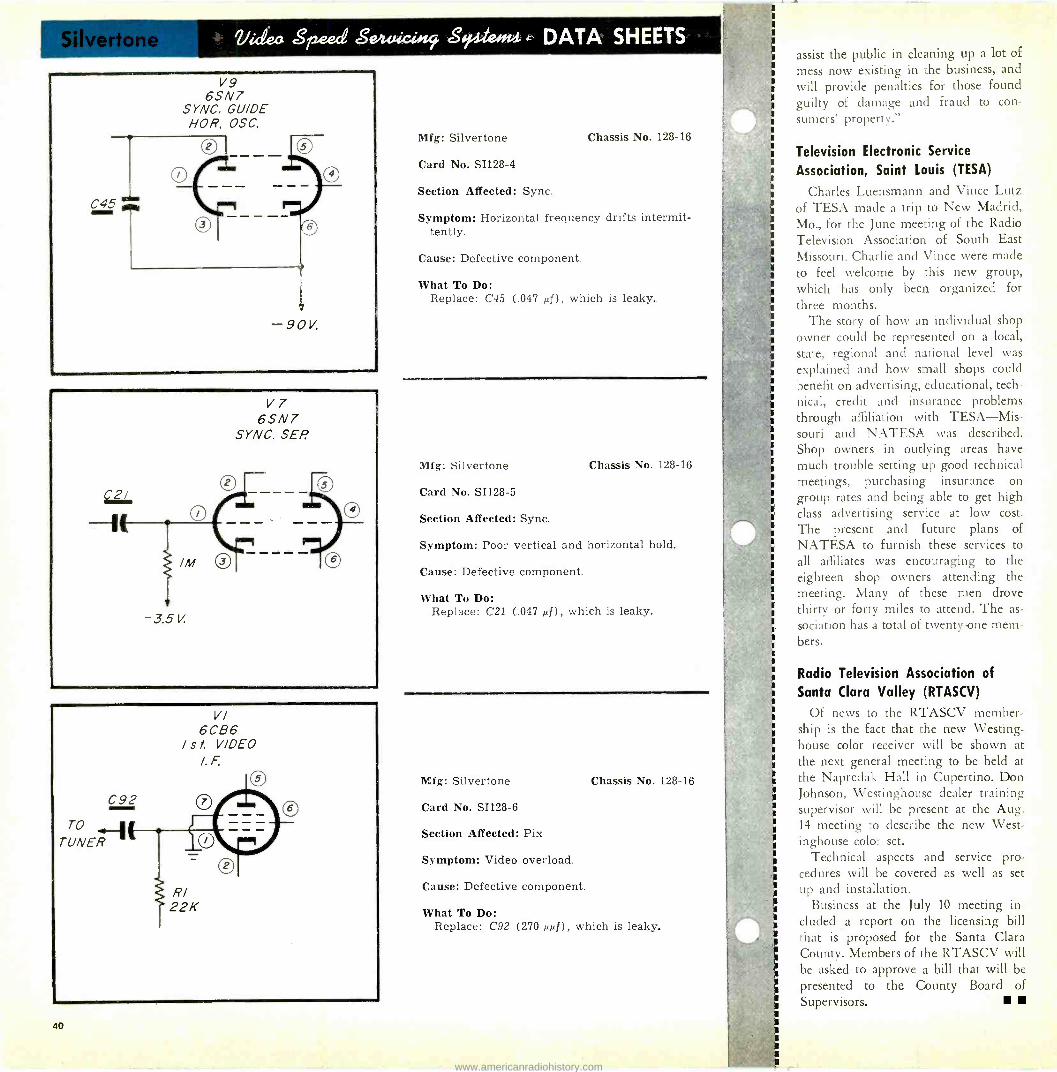
Video Speed Sm4xieülf Seileoft4 c DATA SHEETS
V7 6SN7
SYNC. SEP.
/M
-3.5 V
Mfg: Silvertone
Card No. SI128-4
Section Affected: Sync.
Chassis No. 128-16
Symptom: Horizontal frequency drifts intermit- tently.
Cause: Defective component.
What To Do: Replace: C45 (.047 sf), which is leaky.
Mfg: Silvertone Chassis No. 128-16
Card No. SI128-5
Section Affected: Sync.
Symptom: Poor vertical and horizontal hold.
Cause: Defective component.
What To Do: Replace: C21 (.047 AD, which is leaky.
Mfg: Silvertone
Card No. SI128-6
Section Affected: Pix
Symptom: Video overload.
Cause: Defective component.
Chassis No. 128-16
What To Do: Replace: C92 (270 µµf), which is leaky.
assist the public in cleaning up a lot of mess now existing in :he business, and will provide penalties for those found guilty of damage and fraud to con-
sumers' property."
Television Electronic Service
Association, Saint Louis (TESA)
Charles Luensmann and Vince Lutz of TESA made a trip to New Madrid, Mo., for the June mee:ing of the Radio Television Association of South East Missouri. Charlie and Vince were made to feel welcome by this new group, which has only been organized for three months.
The story of how an individual shop owner could be represented on a local, state, regional and national level was explained and how small shops could benefit on advertising, educational, tech- nical, credit and insurance problems through affiliation with TESA-Mis- souri and NATESA was described. Shop owners in outlying areas have much trouble setting up good technical meetings, purchasing insurance on group rates and being able to get high class advertising service at low cost. The present and future plans of NATESA to furnish these services to
all affiliates was encouraging to the eighteen shop owners attending the meeting. Many of these men drove thirty or forty miles to attend. The as-
sociation has a total of twenty-one mem- bers.
Radio Television Association of Santa Clara Valley (RTASCV)
Of news to the RTASCV member- ship is the fact that the new Westing- house color receiver will be shown at the next general meeting to be held at the Napredak Hall in Cupertino. Don Johnson, Westinghouse dealer training supervisor will be present at the Aug. 14 meeting to describe the new West- inghouse color set.
Technical aspects and service pro- cedures will be covered as well as set up and installation.
Business at the July 10 meeting in- cluded a report on the licensing bill that is proposed for the Santa Clara County. Members of the RTASCV will be asked to approve a bill that will be presented to the County Board of Supervisors.
40
www.americanradiohistory.com

THE ANSWERMAN
Inquiries Sent To The Answerman Will Be Acknowledged Only
If Accompanied By Radio-TV Service Firm Letterheads Or Similar
Identification.
BY SERVICE DEALER & ELECTRONIC SERVICING TECHNICAL STAFF
Dear Sir: I come across a job to add a VU
meter to a tape recorder in connection with a mixer for a Hi-Fi fan. The recorder has a "Magic Eye" volume indicator only.
Maybe the "Answer Man" or Mr. Lawrence Fielding will mention a
proper information in his "The Serv- ice Dealer and Hi -Fidelity."
W. R. Brooklyn, N. Y.
Inserting a VU meter in a tape re-
corder may be accomplished in accord- ance with Fig. 1. A properly damped VU meter should be used, although so-
called "power -level" meters will do a
fair job. The former cost about $42.00
39001E V.U. METER
RECORDING HEAD
CALIBRATION CONTROL, FOR SETTING UP CORRECT
OPERATING PO/NT OF V. U METER
/K 1/2 WATT
BREAK CONNECTION IN SERIES WITH ONE SIDE OF RECORD -HEAD.
Fig. 1-How to connect a VU meter to
tape recorders.
list, whereas the latter may be obtained at a list of about $17.00 or 18.00.
The potentiometer is suggested in the circuit because not all recording heads require the same energizing current. Since you did not specify the type of
recorder in question, I am suggesting a
value of potentiometer which will
cover most commercially available units. Your job will be to CALIBRATE the meter so that it reads just below full
scale at the point of tape overload, but since you have the eye indicator, this should prove to be fairly simple.
Dear Sir: I have a problem that has mystified
me and may interest some of your read- ers. The receiver is a Travler 46A3. The receiver was examined and it was found that the contrast control was burned open. This looked simple enough. There was no picture or sound.
The audio take-off is in the plate cir-
cuit of the video amplifier which ex-
plains the lack of audio. I thought at
first the problem was only going to in-
volve an open contrast control. I re-
placed the control and turned on the receiver. Still no sound and no picture. The new contrast control burned in a
short time. I referred to the schematic, looked it
over, measured a couple of voltages and [Continued on page 43]
SPECIAL OFFER
TO OUR READERS! By special arrangement with John F.
Rider Publisher, Inc., SERVICE DEALER
and ELECTRONIC SERVICING now brings you a COMPLETE diagram serv- ice fo help you do a faster, easier serv- icing job!
ALL COMPLETE! ALL FACTORY PREPARED! ALL FACTORY
AUTHORIZED!
Just $1.25 for COMPLETE SERVICING IN- FORMATION on any TV receiver ... any year, any make, any model ... from 1946
on!
Just 75t' for COMPLETE SERVICING IN-
N FORMATION on any radio . any year, any make, any model ... from 1941 on!
TAKE ADVANTAGE OF THIS SPECIAL
OFFER ... MAIL THE COUPON TODAY!
I COWAN PUBLISHING CORP. I 67 W. 44 Street, New York 36, N. Y.
Please RUSH me the the following diagrams:
TV DIAGRAMS @ $1.25 EACH
CHASSIS # MAKE MODEL
RADIO DIAGRAMS @ 750 EACH
CHASSIS e MAKE MODEL
MAKE CHECKS & MONEY ORDERS PAYABLE TO COWAN PUBLISHING CORP.
!For all New York City orders, please submit additional 3' soles tax.)
Name
I Address
I City State L -
SERVICE DEALER and ELECTRONIC SERVICING AUGUST, 1956 41
www.americanradiohistory.com

NEW TWIST in REAMING!
Extra leverage-just in sert 3/16" blade or pin
The new XCE- LITE No. 39 chrome plated reamers give you extra ca- pacity - up to 1/2" reaming-chrome-hard cutting edges-plus this handy 3/16" leverage hole. Just insert 3/16" screwdriver or pin-you have the leverage of a T -type reamer plus the convenience of the famous XCELITE handle! Get No. 39 (with fixed handle) or 99-39 (fits your 99 Kit handle - your distributor stocks it with his new No. 99 replacement kit). An ideal addition to your 18" to 38" XCELITE SUPER - REAMERS!
No. 39 reamer fixed
in handle
XCELITE, Incorporaed Dept. R
Orchard Perk, New York
For Originality Look to XCELITE
FOR LONGER SERVICE LIFE
you can rely on... LYTICAP ELECTROLYTIC CAPACITORS
You can recognize PLANET LYTICAPS by their shiny red cardboard jackets and their general neat work- manlike appearance. Available in all frequently used capacities from 3 to 500 volts, they are ideal for all types of service work-radio-television-industrial.
PLANET LYTICAPS ore 100% tested for capacity and leakage; they receive a rigid mechanical inspection. Like all Planet products, they are fully guaranteed for one year. No wonder so many set manufacturers use them as original equipment) *Registered
Ask for PLANET LYTICAPS by name at your regular parts jobber.
BIG 1/2,
CAPACITY
No. 99.39 detachable
reamer
PLANET SALES CORP. BLOOMFIELD, N.J.
TRADE FLASHES [from page 23]
Requirements for a service dealer's license are that he must have a certified technician's license or regu- larly employ a full-time certified technician.
It does not apply to any employee of a licensed serv- ice dealer under direction of a certified technician. That is to say, only one certified technician is re- quired.
Students or apprentices accompanied and super- vised by a certified technician are not required to have licenses but must carry identification cards.
As approved, the ordinance is a compromise be- tween proposals made earlier requiring that all en- gaged in doing repair work or running a business be licensed and those proposals opposing licensing en- tirely. The television service association advocated the licensing proposal.
The requirements of a certified technician are that he must be over 21 years old, have four or more years of experience in servicing equipment, or have tech- nical training (trade, college or correspondence school) equivalent to two years, with a minimum of one year's practical experience.
A service dealer's annual license fee is $25 and a certified technician's $10.
A board of examiners is to be selected and pro- vision made for administration and enforcement of the ordinance. Members of the examining board will include three service dealers, an instructor of a TV school and an engineer from one of the local TV stations.
Industry -wide plans for the observance of Na- tional Television Week, Sept. 23-29, began to jell as manufacturers, dealers and broadcasters spelled out their individual and collective sales promotion campaigns.
Celebration of the Week again will be under the joint sponsorship of the Radio -Electronics -Tele- vision Manufacturers Association (RETMA), the Na- tional Association of Radio and Television Broad- casters (NARTB), the National Appliance and
Radio-TV Dealers Association (NARDA), and the Television Advertising Bureau.
RETMA and the other sponsoring organizations adopted the following slogan for this year's promo- tion campaign: "National Television Week-Cele- brating the Finest Home Entertainment in Sight".
With the termination of Capehart's Television - Radio and High Fidelity Production and Sales-Mr. F. B. "Ted" Ostman, Director of Capehart-Farns- worth Company Service Operations will join the Federal Electric Corporation, another I T & T Divi- sion. Mr. Ostman will be Staff ConJultant to Major General Francis H. Lanahan, Executive Vice -Presi- dent.
Robert C. Kocmoud is the new sales promotion manager of General Cement Mfg. Co., Rockford, Illinois, and all that firm's sales divisions. The appoint- ment was made recently by Stanley B. Valiulis, G -C president. Mr. Kocmoud brings to his new position several years' work with the advertising department of a large mail order company.
The two-way radio communications industry, through the Radio -Electronics -Television Manufac- turers Association, announced plans looking toward the inauguration of an extensive educational and liaison program for the industry.
In accordance with this program, Carroll M. White, who has had many years experience in mili- tary, municipal and industrial communications, has been employed as Manager of Mobile Radio Com- munications by RETMA. In his new position, Mr. White will conduct a varied and extensive campaign to acquaint the government, industry and the pub- lic with the contributions made by the land mobile communications industry to the over-all economy and safety of the country. He will be stationed in Washington at RETMA headquarters.
MARINE ELECTRONICS [from page 6]
However, unless it has been specifically engineered for marine use, no ac equipment should be grounded in any way, because of the danger of causing electrol- ysis. This applies especially to battery chargers, some of which employ auto -transformers. Connecting them to a boat's batteries (while the batteries are still con- nected to boat circuits) is an invitation to rapid elec- trolysis. More on this in a succeeding chapter.
CORRECTION
The reader's attention is called to two corrections that should be made in Fig. 1 of the June installment of "The Marine Electronic Business" of page 15. The rectifier protective resistor is 22 ohms, not 22K; and the filter resistor is 500 ohms, not 500K. These correc- tions will render the diagram correct in every detail.
42 SERVICE DEALER and ELECTRONIC SERVICING AUGUST, 1956
www.americanradiohistory.com

ANSWERMAN [from page 41]
found that instead of having, as the print called for, 135 volts at the cathode circuit of the 6V6 audio output tube I
had nearly 400 volts. Tracing down the circuit I found that a large voltage was being applied to the contrast control when it should have been much less than 135 volts. I went back over the circuit diagram and found a condenser, EC -17B which was the filter condenser from the bottom of the audio output transformer to the cathode circuit of the audio output tube. Again, I thought, this is an easy one. The 40 µf condenser is shorted and putting too much B plus on the 135 volt line. I checked the con- denser. Needless to say, it was good.
I still haven't found why the contrast control has such a high voltage on it or 400 volts exists at the cathode of the 6V6 audio output tube.
I hope you can help me in this. P. C. Philadelphia, Pa.
In examining the B plus system and the power supply circuit as shown in Fig. 2 of the Travler 46A3 TV chassis it can be noted that there is another way in which 400 volts can appear at
the cathode of the audio output tube besides with a shorted 40 µf condenser (not considering a shorted 6V6 audio output tube). That is, if a short occurs in the power transformer filament wind- ings. If the 5 volt filament winding for the 5U4 tube should short to the 6 volt winding, as shown in Fig. 2 the 400
Fig. 2-Partial schematic of Travler 46A3 chassis showing power supply, audio, and
audio output.
volts on the 5 volt filament winding would also be applied to the 6 volt winding for the 6V6 tube and thus to its cathode circuitry. This is more than likely the cause of the difficulty.
Mr. Answerman: What can be causing the low hum in
the audio output from a television re-
ceiver I have been servicing. When the volume control is turned down the hum is still present from the speaker. It is not very loud but could possibly be considered objectionable.
Naturally, the first thing checked was tubes, then B plus filters. They were all found to be normal. Now what?
I have noticed that when I bring my hand in near the audio circuits there is a change in amplitude of the hum depending upon the position of
my hand. Some locations cause the hum to increase and others reduce the hum.
Would very much appreciate a sug- gestion as to what to try next.
T. R. Dallas, Texas
More than likely your problem is
due to lead dress. In some receivers the ac leads that run to the on -off switch on the volume control pass along side of the audio stages. These leads can very easily induce 60 cycle voltages into the grids, or across the grid leak re-
sistors. Lead dress in this section is more important than many technicians be-
lieve. Fortunately, it is usually solved in the experimental models and the technician is not too often bothered with lead dress problems.
When a hum is present as stated, one of the first steps to locate its cause would be to examine the ac lines run- ning near the volume control and most particularly near the grid leak resistors. Another possibility of this difficulty may be the vertical deflection leads, such as those that feed the vertical out- put transformer. These wires must definitely be placed away from audio stages.
Also, contrast control or video sig- nal leads running near audio circuits
$3.25
`7 each
QUICK -CHANGE 5AXP4 HOLDER
Permits Speedy Yoke Changing
TELE-SCOPIC PRODUCTS, INC.
FOR HANDLING CHASSIS
WITHOUT CUTTING FINGERS
CHASSIS HOLDERS $1.00
pair 215 W. 33rd St. New York 1, N.Y.
Why "The Man On The Roof"
prefers
for making superior television antenna installations
Take "Snap -In" Type
CHIMNEY MOUNTS and WALL BRACKETS for instance . . .
Unique U Bolts instead of two screws make for quick, simple, antenna installation. Spring tension on steel mast retainers holds antenna mast while Special U Bolts are inserted and tightened. Saves installer time - permits greater safety. Same features are included in Snap -In Wall Brackets.
"Special U
I far superior screws"
Bolt is to two 1
SN50 CHIMNEY MOUNT (Two To A Set)
r ---- 1
"Hot -Dip Galvanized F .
for rust resistance prevents ugly I
rust streaking" I
r "Need only one hand
1
and spintite for secur- I
ing mast"
\ri
"One hand can be used to hold on to the mast, ladder or mounting for greater safety"
-,
time fumbling "Saves 1
with screws and screwdriver. Only one man needed on roof"
,11r. Installer: DON'T BE SWITCHED-IT'S YOUR TIME AND SAFETY
Your Distributor has these in stock or can order and receive them immediately. If your dis- tributor does not handle South River products, please write us on your business letterhead. We'll
see him at once and tell him the story of South River superiority. Products made better by design - with the installer in mind MAKE IT EASY FOR YOURSELF . . . Better for your Customers
Insist on mountings and accessories made by
METAL PRODUCTS CO., INC. South River, New Jersey
PIONEER MANUFACTURER AND OUTSTANDING PRODUCER OF THE FINEST LINE OF ANTENNA MOUNTING ACCESSORIES
WRITE FOR OUR 1956 CATALOG
SERVICE DEALER and ELECTRONIC SERVICING AUGUST, 1956 43
www.americanradiohistory.com
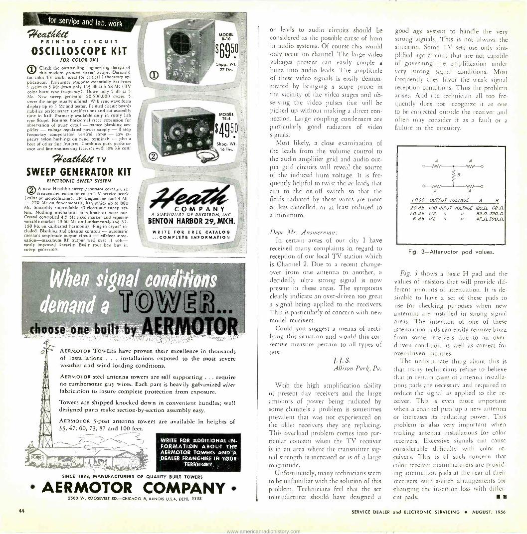
for service and lab. work
PRINTED CIRCUIT OSCILLOSCOPE KIT
fOR COLOR TV!
0Check the outstanding engineering design of this modern printed circuit Scope. Designed
for color TV work, ideal for critical Laboratory ap- plications. Frequency response essentially Hat from 5 cycles to 5 Mc down only 111 db at 3.58 Mc (TV color burst sync frequency). Down only 5 db at 5
Mc. New sweep generator 20-500,000 cycles, 5. times the range usually offered. Will sync wave form display up to 5 Mc and better. Printed circuit boards stabilize performance specifications and cut assembly time in half. Formerly available only in costly Lab type Scope. Features horizontal trace expansion for observation of pulse detail - retrace blanking am- plifier - voltage regulated power supply - 3 step frequency compensated vertical input - low ca- pacity nylon bushings on panel terminals - plus a
host of other fine features. Combines peak perform- ance and fine engineering features with low kit cost'
Nzecteldeez T v
SWEEP GENERATOR KIT ELECTRONIC SWEEP SYSTEM
OA new Heathkit sweep generator covering all frequencies encountered in TV service work
(color or monochrome) . FM frequencies too! 4 Mc - 220 Mc on fundamentals, harmonics up to 880 Mc. Smoothly controllable all -electronic sweep sys- tem. Nothing mechanical to vibrate or wear out. Crystal controlled 4.5 Mc fixed marker and separate variable marker 19-60 Mc on fundamentals and 57- 180 Mc on calibrated harmonics. Plug-in crystal in- cluded. Blanking and phasing controls - automatic constant amplitude output circuit - effcient atten- uation-maximum RF output well over .1 volt- vastly improved linearity. Easily your best buy in sweep generators.
aose one built b
MODEL o-10
$6950 Shpg. Wt.
27 lbs.
MODEL TS -4
$49 Shpg. Wt.
16 lbs.
50
COMPANY A SUBSIDIARY CF DAYSTROM, INC.
BENTON HARBOR 29, MICH.
WRITE FOR ! REE CATALOG ...COMPLETE INFORMATION
AERMOTOR TOWERS have proven their excellence in thousands of installations . . . installations exposed to the most severe weather and wind loading conditions.
AERMOTOR steel antenna towers are self supporting ... require no cumbersome guy wires. Each part is heavily galvanized after fabrication to insure complete protection from exposure.
Towers are shipped knocked down in convenient bundles; well designed parts make section -by -section assembly easy.
AERMOTOR 3 -post antenna towers 33, 47. 60, 73, 87 and 100 feet.
are available in heights of
WRITE FOR ADDITIONAL IN- FORMATION ABOUT ABOUT THE AERMOTOR TOWERS AND A DEALER FRANCHISE IN YOUR
TERRITORY.
SINCE 1888, MANUFACTURERS OF QUALITY BUILT TOWERS
AERMOTOR COMPANY 2500 W. ROOSEVELT RD.-CHICAGO 8, ILLINOIS U.S.A. DEPT.. 33118
or leads to audio circuits should be considered as the possible cause of hum in audio systems. Of course this would only occur on channel. The large video voltages present can easily couple a buzz into audio leads. The amplitude of these video signals is easily demon- strated by bringing a scope probe in the vicinity of the video stages and ob- serving the video pulses that will be picked up without making a direct con- nection. Large coupling condensers are particularly good radiators of video signals.
Most likely, a close examination of the leads from the volume control to the audio amplifier grid and audio out- put grid circuits will reveal the source of the induced hum voltage. It is fre- quently helpful to twist the ac leads that run to the on -off switch so that the fields radiated by these wires are more or less cancelled, or at least reduced to a minimum.
Dear Mr. Ansruerman: In certain areas of our city I have
received many complaints in regard to reception of our local TV station which is Channel 2. Due to a recent change- over from one antenna to another, a
decidedly ultra strong signal is now present in these areas. The symptoms clearly indicate an over -driven too great a signal being applied to the receivers. This is particularly of concern with new model receivers.
Could you suggest a means of recti- fying this situation and would this cor- rective measure pertain to all types of sets.
J.J.S. Allison Park, Pa.
Wtih the high amplification ability of present day receivers and the large amounts of power being radiated by some channels a problem is sometimes prevalent that was not experienced on the older receivers they are replacing. This overload problem comes into par- ticular concern when the TV receiver is in an area where the transmitter sig- nal strength is increased or is of a large magnitude.
Unfortunately, many technicians seem to be unfamiliar with the solution of this problem. Technicians feel that the set manufacturer should have designed a
good agc system to handle the very strong signals. This is not always the situation. Some TV sets use only sim- plified agc circuits that are not capable of governing the amplification under very strong signal conditions. Most frequently they favor the weak signal reception conditions. Thus the problem arises. And the technician all too fre- quently does not recognize it as one to be corrected outside the receiver and often may consider it as a fault or a failure in the circuitry.
LOSS OUTPUT VOLTAGE A B
20 db ///O INPUT VOLTAGE /2011 6811 l O db 1/3 rr rr 8212 22011
6 db 1/2 tr rt 4711390_0_
Fig. 3-Attenuator pad values.
Fig. 3 shows a basic H pad and the values of resistors that will provide dif- ferent amounts of attenuation. It is de- sirable to have a set of these pads to use for checking purposes when new antennas are installed in strong signal areas. The insertion of one of these attenuation pads can easily remove buzz from some receivers due to an over- driven condition as well as correct for over -driven pictures.
The unfortunate thing about this is
that many technicians refuse to believe that in certain cases of antenna installa- tions pads are necessary and required to reduce the signal as applied to the re- ceiver. This is even more important when a channel puts up a new antenna or increases its radiating power. This problem is also very important when making antenna installations for color receivers. Excessive signals can cause considerable difficulty with color re-
ceivers. This is of such concern that color receiver manufacturers are provid- ing attenuation pads at the rear of their receivers with switch arrangements for changing the insertion loss with differ- ent pads.
44 SERVICE DEALER and ELECTRONIC SERVICING AUGUST, 1956
www.americanradiohistory.com
AMPLIFIERS -(Audio, Hi-Fi, P. A.) Allied Radio Corp. 100 N. Western Ave., Chicago 80, III. Blonder -Tongue Labs. Ina. 526 North Ave., Westfield, N. J. Bogen & Co., Inc., David 29 Ninth Ave., New York 14, N. Y. Transvision, Inc. 360 North Ave., New Rochelle, N. Y.
ANTENNAS Amphenol Electronics Corp. 1830 S. 54th Ave., Chicago 50, III. Channel Master Corp. Ellenville. New York Clear Beam Antenna Corp. Canoga Park. Calif. Cornell -Dubilier Electric Corp. South Plainfield, New Jersey Electrend Products Corp St. Joseph, Mich. Finney Company. The 4612 St, Clair Ave., Cleveland 3, Ohio Hi -Lo TV Antenna Corp. 3540 N. Ravenswood Ave.. Chicago 13, III. Holloway Electronics Corp. Fort Lauderdale. Fla. JFD Manufacturing Co., Inc. 6127 16th Ave., Brooklyn 4, N. Y. Philco Corp. Philadelphia 34. Pa. Radiart Corp. 3455 Vega Ave., Cleveland 13, Ohio Radio Merchandise Sales, Inc. 2016 Bronxdale Ave., New York 60, N. Y. Snyder Mfg. Co. 22nd & Ontario Sts.. Philadelphia 40, Pa. Technical Appliance Corp. Sherburne, New York Telco Electronics Mfg. Co. __.__...... _.. 919 Taylor Ave.. Rockford. 111. mires, Inc. Asubry Park, N. 1. Walsco Electronics Corp. 3602 Crenshaw Blvd , Los Angeles 16, Cal. Winegard Company 3000 Scotten Blvd., Burlington, Iowa
ANTENNA ACCESSORIES Alliance Manufacturing Co. Alliance, Ohio Am phenol Electronics Corp. 1830 S. 54th Ave Chicago 50, Ill. Blonder -Tongue Labs, Inc. 526 North Ave.. Westfield, N. J. Channel Master Corp. Ellenville, New York General Cement Mfg. Co. 919 Taylor Ave., Rockford, III. I. E. Manufacturing Co. 325 N. Hoyne Ave., Chicago 12, III. 1 F D Manufacturing Co., Inc. 6127 16th Ave.. Brooklyn 4. N. Y. Jontz Manufacturing Co. 1101 E. Mc inlay Ave., Mishawaka, Ind. Kenwood Engineering Co. 265 Colfax Ave., Kenilworth, N. J. Mosley Electronics 8622 St. Charles Rock Rd., St. Louis 14, Mo. Mueller Eelectric Co. 1583 E. 31st Street, Cleveland 14, Ohio Philco Corp. Philadelphia 34. Pa. Radiart Corp. 3455 Vega Ave., Cleveland 13, Ohio Radio Merchandise Sales, Inc. 2016 Bronxdale Ave., New York 60, N. Y. South River Metal Products Co., Inn South River, New Jersey Superex Electronics Corp. 6 Radford Place, Yonkers, N. Y.
BATTERIES
Burgess Battery Co. Freeport, Illinois RCA, (Tube Div.) Harrison, New Jersey
BOOKS & MANUALS Cisi n, Harry G. Cowan Publishing Corp. Electronic Publishing Co. Rider, John F., Publisher Sams, Howard W. & Co.. Inc. United Catalog Publishers
Amagansett, N. Y. 67 West 44th Street, New York 36, N. Y.
180 N. Wacker Drive, Chicago 6, III. 480 Canal Street, New York 13, N. Y.
2201 E. 46th Street. Indianapolis 5, Ind. 110 Lafayette Street, New York 13, N. Y.
BUSINESS ORDER FORMS Electronic Publishing Co. 180 N. Wacker Drive, Chicago 6, Ill. Oelrich Publications 4308 N. Milwaukee Ave., Chicago 41. III.
CAPACITORS A erovox Corp. New Bedford, Mass. Astron Corp. 255 Grant Ave., East Newark, N. J. Centralab. Div. of Globe -Union 900 E. Keefe Ave., Milwaukee I. Wisc. Cornell-Dubilier Electric Corp. South Plainfield, New Jersey Erie Resistor Corp. Erle. Pa. Illinois Condenser Co. _.. 1616 N. Throop St., Chicago 22. Ill. Planet Sales Corp. 225 Belleville Ave., Bloomfield, N. J. Pyramid Electric Co. 1445 Hudson Blvd., North Bergen, N. J. Sprague Products Co. 71 Marshall Street, North Adams, Mass.
CHEMICALS. SPRAYS, LUBRICANTS Electronic Chemical Corp. .. 813 Comm unipaw Ave.. Jersey City 4, N. J. General Cement Mfg. Co. .. _. _. _.. 919 Taylor Ave.. Rockford, Ill. Great Eastern Mfg. Co. 165 Remsen Ave., Brooklyn 12. N. Y. Krylon. Inc. Ford & Washington Sts.. Norristown. Pa. Quietrole Co., Inc. Spartanburg, South Carolina Superes Electronics Corp. 6 Radford Place, Yonkers. N. Y. Telematic Industries, Inc. 16 Howard Ave.. Brooklyn 21, N. Y. Walsco Electronics Corp. __. 3602 Crenshaw Blvd.. Los Angeles 16, Cal.
CHOKES, COILS & TRANSFORMERS (RF) Acme Electric Corp. .._. _ .. 468 Water Street, Cuba, New York Chicago Standard Transformer Corp. .. 3501 Addison Street. Chicago 18, III. Merit Coil & Transformer Corp. 4427 N. Clark Street, Chicago 40, III. Miller. J. W. Company 5917 S. Main Street. Los Angeles 3, Cal. Superes Electronics Corp. 6 Radford Place, Yonkers, N. Y. Triad Transformer Corp. 4055 Redwood Ave., Venice. Cal.
CHOKES, COILS & TRANSFORMERS (Audio and Line Freq.)
Acme Electric Corp. 468 Water Street, Cuba, New York Chicago Standard Transformer Corp. 3501 Addison Street, Chicago 18. III. Delco Radio (Div. of General Motors Corp.) . Kokomo. Indiana Merit Coil & Transformer Corp. 4427 N. Clark Steet. Chicago 40, III. Parma. Power Company .. _ 4721 N. Dam en Ave., Chicago 25, III. Triad Transformer Corp. 4055 Redwood Ave., Venice, Calif.
CHOKES, COILS & TRANSFORMERS (Deflection & Focusing)
Acme Electric Corp. _. _. _. _ 468 Water Street, Cuba, New York Chicago Standard Transformer Corp. _ 3501 Addison Street. Chicago 18, III. Great Eastern Mfg. Co. 165 Remsen Ave., Brooklyn 12, N. Y. Merit Coil & Transformer Corp. 4427 N. Clark Street, Chicago 40, III. Perma-Power Company 4721 N. Damen Ave., Chicago 25, III. Ram Electronic Sales Co. Irvington, New York Super« Electronics Corp. 6 Radford Place, Yonkers, N. Y. Triad Transformer Corp. 4055 Redwood Ave., Venice, Calif.
CONNECTORS, PLUGS Blonder -Tongue Labs, Inc. 526 North Ave., Westfield, N. J. Cannon Electric Co. _. P. 0. Box #75, Los Angeles 31, Calif. Eby Sales Co. of N. Y. 130 Lafayette Street. New York 13, N. Y. General Cement Mfg. Co. ........ 919 Taylor Ave., Rockford, III. Mosley Electronics ... 8622 St. Charles Rock Rd.. St. Louis 14, Mo. Radio Merchandise Sales. Inc. 2016 Bronxdale Ave., New York 60, N. Y.
FUSES Bussmann Mfg. Co. University and Jefferson, St. Louis 7, Mo. Littelfuse, Inc. 4751 N. Ravenswood Ave., Chicago 40, III,
BUYER'S DIRECTORY OF
ADVERTISED PRODUCTS This department is an additional service
to our readers and advertisers. It is not intended to cover all products in all cate- gories, Tor is it intended to cover all prod- ucts mode by any manufacturer.
The classifications are broad. Under each is listed the name and address of only those manufacturers who have, in the recent past, or who are currently advertising these par- ticular products in this publication.
This service is not a part of the adver- tiser's contract. The listings may change in
future issues. Every reasonable precaution is taken to avoid errors and omissions.
HARDWARE I. E. Manufacturing Co. Kenwood Engineering Co. Mueller Electric Co. South River Metal Products Co., Inc. Television Hardware Mfg. Co. Walsco Electronics Corp. 3602
325 N. Hoyne Ave., Chicago 12, III. 265 Colfax Ave.. Kenilworth, N. J.
83 E. 31st Street, Cleveland 14. Ohio South River. New Jersey
919 Taylor Ave., Rockford, III. Crenshaw Blvd., Los Angeles 16, Cal.
MICROPHONES, Stands & Accessories American Microphone Co. 370 S. Fair Oaks Ave., Pasadena 3, Cal. Atlas Sound Corp. 1446 39th Street, Brooklyn 18, N. Y. Shure Bros Inc. 222 Hartrey Avenue. Evanston, III.
PHONOGRAPH NEEDLES Jensen Industries, Inc. 342 S. Wood Street, Chicago 12, III. Permo, Inc. 6415 N. Ravenswood Ave.. Chicago 26, Ill. Recoton Corp. 52-35 Barnett Ave., Long Island City 4, N. Y. Walco-Electrovox Co.. Inc. 60 Franklin Street. East Orange, N. J.
PHONOGRAPH PICKUPS & CARTRIDGES American Microphone Co. 370 S. Fair Oaks Ave., Pasadena 3, Cal. Electro -Voice, Inc. Buchanan, Michigan Shure Brothers, Inc. 222 Hartrey Avenue. Evanston, III. Sonotone Corp. Elmsford, New York
POWER SUPPLIES (Converters & Inverters) American Television & Radio Co. 300 East First St., St. Paul 1, Minn. Electro Products Labs, Inc. 4501 N. Ravenswood Ave., Chicago 40, III. Parma -Power Company 4721 N. Damen Ave., Chicago 25, III. Vokar Corporation Dexter 2, Michigan
RESISTORS & CONTROLS Aerovox Corp. New Bedford, Mass. Centralab, Div. of Globe -Union 900 E. Keefe Ave., Milwaukee I, Wisc. Clarostat Mfg. Co., Inc. Dover, New Hampshire Delco Radio, Div. of General Motors Corp. Kokomo, Indiana Erie Resistor Corp. Erie, Pa. International Resistance Co. 401 N. Broad St., Philadelphia 8. Pa.
SEMI -CONDUCTORS C BS- Hytron 100 Endicott Street, Danvers, Mass. Federal Telephone & Radio Corp. 100 Kingsland Road, Clifton, N. J. General Electric Co. Schenectady, New York Philco Corp. _ Philadelphia 34, Pa.
Harrison, New Jersey Newton, Mass.
RCA. (Tube Div.) ..
Raytheon Mfg. Company Tarzian Inc., Sarkes 415 N. College Ave.. Bloomington, Ind. Tung -Sol Electric, Inc. 95 Eighth Ave., Newark 4, N. J.
SERVICING AIDS Allied Radio Corp. 100 N. Western Ave., Chicago 80, III. American Phenolic Corp. 1830 S. 54th Ave., Chicago 50. III. Belden Manufacturing Co. 4647 W. Van Buren St.. Chicago 80, III. Blonder -Tongue Labs, Inc. 526 North Ave.. Westfield, N. J. Colman Tool & Machine Co P.O. Box 7026, Amarillo, Tex. Columbia Wire & Supply Co. 2850 Irving Park Road, Chicago 18, III. Electric Soldering Iron Co. Deep River, Conn. Electronic Publishing Co 180 N. Wacker Drive, Chicago 6. Ill. General Cement Mfg. Co. 919 Taylor Ave., Rockford, III. Mall Tool Company . 7740 South Chicago Ave., Chicago 19. III. Oelrich Publications 4308 N. Milwaukee Ave., Chicago 41, III. Quietrole Co., Inc. Spartanburg, South Carolina Ram Electronic Sales Co. Irvington, New York Tele-Scopic Products. Inc. 215 W. 33rd Street, New York I, N. Y. Ungar Electric Tools, Inc. _. P. 0. Box 312. Venice, Calif. United Catalog Publishers 110 Lafayette Street, New York 13. N. Y. Vaco Products Co. 317 E. Ontario Street, Chicago II, III. Wall Mfg. Co Grove City, Pa.
N. 15 St..Phila. Weller Elec. Corp. 160, Pa. Wen Products, Inc. 5806 Northwest Highway, Chicago 31. III. Xcelite, Inc Thorne Ave. and Bank St.. Orchard Park, N. Y. Yeats Appliance Dolly Sales Co. 2133 N. 12th Street, Milwaukee 5, Wisc.
SPEAKERS (including phones) Atlas Sound Corp. 1446 39th Street, Brooklyn 18. N. Y. Delco Radio. Div. of General Motors Corp. Kokomo, Indiana Jensen Mfg. Company 6601 S. Laramie Ave., Chicago 38, III.
North American Philips Co., Inc. 100 East 42nd Street. New York 17, N. Y. Oxford Electric Corp. 3911 S. Michi can Ave.. Chicago 15, Ill. Philco Corp. Philadelphia 34, Pa. Quam -Nichols Company Marquette Rd. & Prairie Ave., Chicago 37, III. Telex Telex Park, St. Paul, Minn. University Loudspeakers, Inc. 80 S. Kensico Ave., White Plains, N. Y.
SPEAKER ENCLOSURES Jensen Mfg. Company 6601 S. Laramie Ave., Chicago 38, Ill. Transvision, Inc. 460 North Ave.. New Rochelle, N. Y. University Loudspeakers, Inc 80 S. KENSICO AVE.. White Plains, N. Y.
TEST EQUIPMENT & INSTRUMENTS American Scientific Development Co. ....334 S. Main St.. Fort Atkinson, Wise. B & K Manufacturing Co. .... 3731 N. Southport, Chicago 13, Ill. Central Electronics, Inc. 1247 Belmont Ave.. Chicago, Ill. Electronic Instrument Company (EICO) 84 Withers Street. Brooklyn II, N. Y. Electronic Test Instrument Corp. 13224 Livernois Avenue, Detroit 38, Mich. General Electronic Research Co. _Whitewater, Wisc. Heath Company, The Benton Harbor, Michigan Hickok Electrical Instrument Co. 10533 Dupont Ave.. Cleveland 8, Ohio Hycon Electronics, Inc. 320 S. Arroyo Parkway, Pasadena, Calif. Jackson Electrical Instrument Co. 16 S. Patterson Blvd., Dayton 2. Ohio Leitch Engineering Co. 326 Lincoln St., Manchester, N.H. Moss Electronic Distributing Co., Inc. 38 Murray Street. New York 7, N. Y. Phaostron Company _ 151 Pasadena Ave., South Pasadena, Calif. Philco Corp. .. Philadelphia 34, Pa. Precision Apparatus Co., Inc. 70-31 84th Street. Glendale 27, L. I., N. Y. Probescope Co. 44-05 30th Ave., Long Island City 3, N. Y. Radio City Products Co., Inc. Centre & Glendale Sts., Easton, Pa. Research Inventions & Mfg. Co. 617 F Street, N. W., Washington I, D. C. Seco Mfg. Co. _. 5015 Penn Avenue South. Minneapolis, Minn. Simpson Electric Company ..5200 W. Kinzie Street. Chicago 44, III. Superior Instruments Co. 2435 White Plains Rd., New York 67. N. Y. Telematic Industries, Inc 15 Howard Ave., Brooklyn 21, N. Y. Teletest Instrument Corp. 31-01 Linden Place. Flushing 54, N. Yi. Triplett Electrical Instrument Co. .... .Bluffton, Ohio Weston Electrical Instrument Corp. ....614 Freiinghuysen Ave.. Newark 5, N. J. Winston Electronics, Inc. 4312 Main Street, Philadelphia 27, Pa.
TOOLS Electric Soldering Iron Co Deep River. Conn. General Cement Mfg. Co. 919 Taylor Ave., Rockford, III. Ohmite Manufacturing Co. 3640 W. Howard Street, Skokie. Illinois Philco Corp. Philadelphia 34, Pa. Kraeuter & Co., Inc. 583 18th Avenue, Newark, N. J. Mall Tool Company 7740 S. Chicago Ave.. Chicago 19, III. Tele.Scopic Products, Inc. 215 W. 33rd Street, New York I, N. Y. Ungar Electric Tools, Inc. P. 0. Box 312, Venice. Calif. Vaco Products Co. Wall Mfg. Co.
317 E. Ontario St., Grove ChicagoCity II.
Pa, 111.
.. .
Walsco Electronics Corp. _. 3602 Crenshaw Blvd.. Los Angeles 16. Cal. Weller Elec. Corp. 160 N. 15 St.. Phila., Pa. Wen Products, Inc. 5806 Northwest Highway, Chicago 31, III. Xcelite, Inc Thorne Ave. and Bank St., Orchard Park, N. Y.
TUBES -CRT & RECEIVING Barry Electronics Corp. 512 Broadway, New York 12, N. Y. CBS-Hytron 100 Endicott St., Danvers, Mass. Coco Electronics Co Columbia Ave, and 18th, Irvington 11, N. J. Delco Radio, Div. of General Motors Corp. ...Kokomo. Indiana Federated Television Mart 513 Rogers Ave., Brooklyn 25. N. Y. General Electric Co. Schenectady. N. Y. Philco Corp. .. Philadelphia 34, Pa. RCA, (Tube Div.) Harrison, N. J. Raytheon Mfg. Company Newton, Mass. Tung -Sol Electric, Inc. 95 Eighth Ave., Newark 4, N. J.
VIBRATORS American Television & Radio Co 300 E. First Street, St. Paul I, Minn. Cornell -Dubilier Electric Corp. South Plainfield. New Jersey Delco Radio, Div. of General Motors Corp. ,- -.... Kokomo, Indiana Radiart Corp. 3455 Vega Ave.. Cleveland 13, Ohio Vokar Corporation Dexter 2. Michigan
WIRE -CABLE -HARNESSES American Phenolic Corp. 1830 S. 54th Ave., Chicago 50, III. Belden Manufacturing Co. 4647 W. Van Buren St.. Chicago 80, III. Columbia Wire & Supply Co. 2850 Irving Park Road, Chicago 18. Ill. Eby Sales Co. of N. Y. 130 Lafayette St., New York 13, N. Y. Federal Telephone & Radio Corp. - 100 Kingsland Road. Clifton, N. J. Jersey Specialty Co. Burgess Place. Mountain View, N. J.
Ask For Sprague By Catalog Number
Know what you're getting ... get exactly what you want. Don't be vague ... insist on
Sprague. Use complete ra- dio -TV serv- ice catalog C-610. Write Sprague Products Company, 71 Mar -
shall Street, No. Adams, Mass.
DON'T JUST SAY
CAPACITORS
SPRAGUE® WORLD'SLARCEST CAPACITOR MANUFACTURER
SERVICE DEALER and ELECTRONIC SERVICING AUGUST, 1956 45
www.americanradiohistory.com
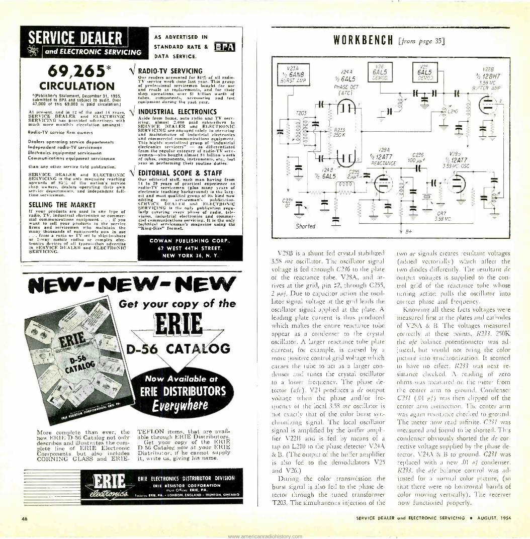
SERVICE DEALER and ELECTRONIC SERVICING
69,265* CIRCULATION
*(Publisher's Statement, December 31, 1955, submitted to BPA and subject to audit. Over 47,000 of this 69,000 is paid circulation.)
At present, and in 12 of the past 16 years, SERVICE DEALER and ELECTRONIC SERVICING has provided advertisers with much more monthly circulation amongst:
Radio-TV service firm owners
Dealers operating service departments Independent radio -TV servicemen Electronics equipment servicemen Communications equipment servicemen
than any other service field publication.
SERVICE DEALER and ELECTRONIC SERVICING is the only magazine reaching upwards of 95% of the nation's service shop owners, dealers operating their own service departments, and independent full- time servicemen.
SELLING THE MARKET If your products are used in any type of radio, TV, industrial electronics or commer- cial communications equipment . if you want to sell your products to the service firms and servicemen who maintain the many thousands of equipments now in use
from a radio or TV set to ship -to -shore or 2 -way mobile radios or complex elec- tronics devices of all types-then advertise in SERVICE DEALER and ELECTRONIC SERVICING.
AS ADVERTISED IN
STANDARD RATE &
DATA SERVICE.
Ni RADIO-TV SERVICING
B PA
Our readers accounted for 84% of all radio - TV service work done last year. This group of professional servicemen bought for use and resale as replacements, and for their shop operations, over $1 k'llion worth of tubes, components, accessories and test equipment during the past year.
INDUSTRIAL ELECTRONICS Aside from home, auto radio and TV serv- icing, almost 2,000 paid subscribers to SERVICE DEALER and ELECTRONIC SERVICING are engaged solely in servicing and maintenance of industrial electronics and commercial communications equipment. This highly specialized group of "industrial electronics servicers" - as differentiated from the regular category of radio -TV serv- icemen-also bought almost $1 billion worth of tubes, components, instruments, etc., last year in performing their routine duties.
EDITORIAL SCOPE & STAFF Our editorial staff, each man having from 14 to 29 years of practical experience as radio -TV servicemen (plus many years of electronic teaching background) is the larg- est and most qualified group of its kind now editing any serviceman's publication. SERVICE DEAIER and ELECTRONIC SERVICING is the only publication regu- larly covering every phase of radio, tele- vision, industrial electronics and commer- cial communications servicing. It is the only technical serviceman's magazine using the "King -Size" format.
COWAN PUBLISHING CORP.,
67 WEST 44TH STREET,
NEW YORK 36, N. Y.
NEW - NEW- NEW Get your copy of the
More complete than ever, the new ERIE D-56 Catalog. not only describes and illustrates the com- plete line of ERIE Electronic Components but also includes CORNING GLASS and ERIE-
t ` J
CATA OG
Now Available at ERIE DISTRIBUTORS
Everywhere
TEFLON items, that are avail- able through ERIE Distributors.
Get your copy of the ERIE D-56 Catalog now at your ERIE Distributor; if he cannot supply it, write us, giving his name.
ERIE ELECTRONICS DISTRIBUTOR DIVISION
. ERIE RESISTOR CORPORATION OH ERIE, PA.
ERIE, PA. LONDON, ENGLAND TRENTON, ONTARIO
WORKBENCH [fieio page 35]
V23 :
6AN8 ;ST '.
T203
2
C231 01TR,
V24A
'/2 6AL5 PHASE OET
(AFC)
V26
6AL5 DEMOD.
6AL5
'
V28A
t/2 12AT7 REACTANCE
IC -11 "±-
C236 100 p).i f
1/26AL5 2µ5f 1 8086`
^ aN
Shorted
V24B'- If --
1
V225
t/2 12BH7
L21?
V2 12AT7
3 58 MO. CSC.
- CR7 3.58 MC.
\2
V28B is a shunt fed crystal stabilized 3.58 me oscillator. The oscillator signal voltage is fed through C236 to the plate of the reactance tube, V28A, and ar- rives at the grid, pin 2, through C255, 2 µµf, Due to capacitor action the oscil- lator signal voltage at the grid leads the oscillator signal applied at the plate. A leading plate current is thus produced which makes the entire reactance tube appear as a condenser to the crystal oscillator. A larger reactance tube plate current, for example, is caused by a
more positive control grid voltage which causes the tube to act as a larger con- denser and tunes the crystal oscillator to a lower frequency. The phase de-
tector (a/c), V24 produces a dc output voltage when the phase and/or fre- quency of the local 3.58 me oscillator is
not exactly that of the color burst syn- chronizing signal. The local oscillator signal is amplified by the buffer ampli- fier V22B and is fed by means òf a
tap on L210 to the phase detector V24A & B. (The output of the buffer amplifier is also fed to the demodulators V25
and V26.) During the color transmission the
burst signal is also fed to the phase de- tector through the tuned transformer T203. The simultaneous injection of the
two ac signals creates resultant voltages (added vectorially) which affect the two diodes differently. The resultant dc output voltages is supplied to the con- trol grid of the reactance tube whose tuning action pulls the oscillator into correct phase and frequency.
Knowing all these facts voltages were measured first at the plates and cathodes of V28A & B. The voltages measured correctly at these points, R233, 250K the afc balance potentiometer was ad- justed, but would not bring the color picture into synchronization. It seemed to have no effect. R233 was next re- sistance checked. A reading of zero ohms was measured on the meter from the center arm to around. Condenser C231 (.01 p.i) was then clipped off the center arm connection. The center arm was again resistance checked to ground. The meter now read infinite. C231 was measured and found to be shorted. This condenser obviously shorted the dc cor- rective voltage supplied by the phase de- tector, V24A & B to ground. C231 was replaced with a new .01 µf condenser. R233, the afc balance control was ad- justed for a normal color picture, (so that there were no horizontal bands of color moving vertically). The receiver now functioned properly.
SERVICE DEALER and ELECTRONIC SERVICING AUGUST, 1956
www.americanradiohistory.com

big reasons why
TROIE . f. P., e.
is "The Choice of Better Service Dealers Everywhere"
) k1FR/T
2 QUAL/TY
3 REI/ABILITY The original product for quieting noisy controls and switches . . . the universal lubri-cleaner for TV and radio . .
Say "QUIETROLE" to your distributor . . .
be sure you get it.
I NO GUM! I NO G° O
GRIME' . 1_, manufactured by
Wet
i
Carried
by recognized
1obbers
everywhere! % I QUIETROLE
COMPANY INC. Spartanburg, South Carolina
IN Active Radio 8 TV Distributors CANADA:> ANADA: 58 Spadino Ave., Toronto 28, Ont.
I-
FREE LITERATURE REQUEST FORM
Valid for 6 weeks only, expires Business Card MUST be attached
z 9/1/56
.D Circle numbers for Free Technical Litera- ture or Information on New Equipment:
p 801 802 803 804 805 806 r 807 808 809 810 811 812
z 813 814 815 816 817 818
tA
I-- If you want more details on products
3 advertised in this issue fill in below:
Page Product o Page Product
u Page Pnoduct
o o
tÀ Name f- U D Title 0 o IY a
W z
Company
Co. Address
City Zone
State
COMMUNITY CAMPAIGNS
Give...the United way
RIDER SPEAKS
[from page 13]
and my wife is slightly more perturbed. I decide that maybe the best thing to do is to go to the club and call another mechanic after I get there. So we dis- connect the charged battery and, lo and behold, the engine continues running and we go to the club.
Now I call another mechanic and de- scribe my difficulty. Within 30 minutes he's at the car. After looking at the ammeter and banging the voltage regu- lator box cover, he declares the gener- ator bad; it must come off. Being stub- born, I ask him if he would check the generator output. No, he has no measur- ing device, but he knows the generator is bad and must be replaced.
I remain stubborn. Two clays later I
get the car back to town and to my regular mechanic. I still have the same battery and the same generator, but a
new set of brushes; the car runs like new.
Don't go away, there's more. The day I get the car fixed my wife
asks me to visit a watch repairman with her. (Several years ago I demonstrated my appreciation of her endurance in living with me for 25 years by buying her a watch from a very reliable estab- lishment.)
Something had happened to the watch early in June and it needed repair. I
suggested that she take it back to the store where I had purchased it. This she did but (unknown to me), when told the repairs would take two weeks, she took it to a watch repairman in the neighborhood. He operated on it, and within a brief period of four weeks she had made four separate visits to him, picking up the watch and return- ing it. It would run for about 48 hours, and then stop. Each time he got it started again he gave a one-year guaran- tee. She now owned four guarantees on a non-functioning watch that was
New PERFO System TI/ tube tester
CANNOT BECOME OBSOLETE!
Model
DM
456
$125
Speed! Tests complete set of tubes In 15 minutes! Compact! Smallest and lightest mutual conduct- ance tester made! Eny to carry.
Permits lull -complement tube testing which must result in increased tube sales
REJUVATESTER RT -203
A CRT tester and rejuvenator in one compact fea- therweight unit!
CA PA CITESTER CT -355
Checks coupling con- densers, under load, without removal from the circuit.
"YSTEM . SEE IT
AT YOUR JOBBER IN SEPT.
FLYBACK TESTER FT -100
Doesn't require a
reference trans- former for corn. parison.
DynaMatic tube tester uses perforated
plastic cards to automatically set up
socket pin connections & test voltages.
For the first time AUTOMATION comes to TV service! No more wait- ing for new roll charts for 6 months to a year, every time new tubes come out. And no more multiple socket panels that become obsolete as soon as a new tube is made. The Dyna- Matic's `PERFO-System' allows you to test the newest tubes and all future tubes as soon as they're out!
Teletest Instrument Corporation 121-08 14th Road
College Point 56, New York
L
I1)lA OF THE `I(1\1r1TII
#300 SERVICE TICKET FILE A new practical low cost system for filing customers service
call and shop job tickets alphabetically in individual file
folders. For instant reference a form is printed on the face
of each folder for summarizing contents. File case is of
heavy cardboard construction in attractive brown simulated
leather finish. File folders are of heavy cream tag stock
with extra flap feature for fast reference (see inset) . .
smartly printed in brown. A to Z file guides are heavy
press board. FILE CASE SIZE 47/6"x 10'/a"x 12'/v" AT YOUR ELECTRONIC PARTS JOBBER
(200 FOLDER CAPACITY)
#300 SERVICE TICKET FILE SYSTEM.......$1.40 (includes case, guides and 100 folders)
#301 BOX OF 100 FILE FOLDERS $2.95
#302 SET OF FILE GUIDES $1.95
OELRICH PUBLICATIONS . ..... ... .
4308 N. MILWAUKEE AVE- CHICAGO 41, ILL. Send me FREE sample Ole folder and colalog.
Nome
Address
City Zen. Stete J
SERVICE DEALER and ELECTRONIC SERVICING AUGUST, 1956 47
www.americanradiohistory.com

Only the 5 TOP-QUALITY brands of_s
STANDARD BRAND TUBES
AT SENSIBLE PRICES 90 Day RETINA Guarantee Brand New
1st quality only Individually boxed
FREEI Newest handy air -mail order form for your ordering convenience. -Free!
Lists ALL popular TV & radio types. Makes mail -ordering a real pleasure. Orders over $25.00 (with remittance) postpaid
Z4 A X2 B3GT H5GT
$ .60 6AS6 1.15I6AS8 _.
.95 6AT6
.8065T8 ..
2.25 1.20 .60
1.10717
7F8 7G7 ..... .... 7H7
..._
1.20 ... 1.1
.85 .. 1.3;
L4 . .85,6AU4GT .... 1.10 71(7 1.20 L6 .. 1.10 6AUSGT .... 1.25 7L7 1.1 LA4 .. _. 1.00 6A U6 .75 7N7 .95 LA6 .... .. I 00 SAW .90 707 1.00 L84 .... I.00,6AV5GT .... 1.20 7R7 .... . 1.30 LC5 1.00 6A V6 .60 7V7 1.30 LC 1.207W7 ........... 1.30 LD 5 .. Ij6AW8 .00 6AX4GT .... .90 7X7 1.00 LE3 ._ ._. .. 1.006AX5GT .... .90 7Y4 .70 LG5 1.00 6856 .......... .70 7Z4
-- . .70
LH4 1.00 6BA7 _....... .9012A4 .85 LN5 1.00 6BC4 1.60 12A L5 .70 NSGT .95 6BC5 .75 12505 .7; Q5GT 1.15 6BC7 1.25 12ATfi .65 84 1.00 6E4051.40 12AT7 1.00 R5 .85 6608 _... .. .75 12AU6 __.... .70 S4 .90 6B E6 .75 12A U 7 .85 S5 .756BF5 ... .9012AV6 .65 T4 .85 68 F6 .70 12A V7 1.05 T5GT .... 1.0566G6G 1.8512ÁW6 1.00 U4 .80 6BH6 .90 12AX4GT .. 1.00 U5 .75 6816 .85 12AX7 ... .. .90 V .9568K5 1.15 12AY7 1.75 V2 _. .70 68K7A 1.15 12ÁZ7 .95 X2B 1.00GBL7GT 1.2512B4A ........ .90
2AF4A . 1.40 68N6 1.1512BA6 .70 2021 1.00 6BQ6GTA .. 1.45 128A7 .95 2X2 .50 68075 1.30 12BD6 .75 3A3 1.10 GBX7GT .... 1.25 12BE6 ...... .75 3A4 .55 6BY56 1.30 12BF6 .70 3A5 .75 6876 .......... .80 12BH7A I.00 3A L5 .... ....... .70 6877 1.35 128 K5 1.10 3AU6 .75 6C4 .60 12BQ6GTB ..1.45 3A V 6 .65 6C5 .80 128X7 .90 3856 .75 6CB5 4.50 126Y7A 1.05 3BC5 .80 6C 88 .75 12877 1.10 38E6 .75 6C1)60 1.90 12CA5 .80 3BN6 .. 1.05 6C F6 .90 12CÚ6 1.45 3BY6 .90 6CG7 .911 12L6 .80 3626 .80 6CL6 1.20 I2SA7GT .... 1.00 3C B6 .85 6C M6 .85 12SC7 .80 3CF6 .85 6CS6 .75 12S17 .75 3CS6 .80 6C U6 1.45 I2SK7GT ... .80 3LF4 1.20 6DC6 .95 I2SL7GT _.. 1.00 3Q4 .85 60E6 .80 I2SN7GTA .85 3Q5GT 1.00 fiF5 .85 12S127G1 _. .75 3S4 .80 fiF6G ......... .80 I2V6GT .80 3V4 .85 6H6 ,75I2WIiGT .. .. .95 4BQ7A ........ 1.30 6J4 3.95 14A4 .. 1.00 4877 1.35 615 .75 1455 ... ....... 1.50 5A M 8 1.05 616 .70 14A7 .. . _.. .85 5AN8 ._ . ._.. 1.10 6K6GT .75 14AF7 ....... 1.00 5AQ5 .75 61(7 ,90 14136 .85 5AS8 1.10 61(8 1.25 14C7 .... ...... 1.00 5518 1.10 6L6GA 1.30 14E8 1.20 5AY8 1.15
.. ... 61661......... 1.75 14E7 1.30
5AW4 . 1.15 6N7 1.20 14F7 .. 1.00 5A74 .60 607 1,00 14F8 1.30 581(7 1.10 654 ,7g 14H7 ._. 1.00 516 .95 6S8GT 1.10 14N7 1.00 514 1.75 6SA7GT .90 1487 -. .95 518 1.10
.
6SC7 ......... 1.00 14R7 1.30 5U4G .70 6SF5 .75 14S7 .. . 1.25 5U4G8 ........ .75 6SF7 ,95 14W7 1.35 5U8 1.10 6SG7 1.00
2919 1.20
5V4G 5V6GT
1.00 .70
6SH7 6SJ7M 95 5AVSGT
25AX4GT 1.30 1.10
5W4GT .70 6SK7GT .
.85
.85 2561(5 1.10 5X4G .80 6S17GT .. 1.00 25BQ6GTB 1.45 5X8 1.05 6SN7GTA/B .90 25CD6GA .. 1.85 5Y3GT .60 6SQ7GT . ,75 25C U6 1.45 5V4G .65 6SR7 .. . .75 251.661 .75 573 .90 614 .. _. 1.30 25W4GT .... .85 574 1.25 6T8 .. I.10 25Z5 .80
fiABGT 1.10 6U8 . I.10 25Z6GT .85 6564 .70 6V3ñ 1.50 3555 .75 GACSGT 1.15 6V6GT .75 3565 .70 6AC7 1.15 6V6M 1.35 35C5 .70 6507G 1.55
_. 6W4GT .80 35L6G1 .65
6AF4 1.35 6W6GT .95 35W4 .55 r,AFfiG 1.20 6X4 .55 35Y4 .75 GAGS .80 6X5GT .55 3575 .60 6AG7 1.35 6X8 1.20 41 .85 6AH4GT 1.00 6Y6G .95 42 . .75 6AH6V 1.05 755 .95 43 .85 6515 1.75 7A6 .80 5055 .75 6A K5 .80 7A7 .85 5065 .. .75 6A K6 .80 758 .80 5005 ,75 6515 _... .657AG7 1.0050L6GT ...... .75 6AL7GT ... 1.657AH7 1.00 50X6GT ..... .90 6A M4 1.55 7B4 .80 50Y6GT 1.00 6AM8 .... .._. 1.15 7B5 .70 50Y7GT .. ... .90 6AN4 1.50 766 1.00 70L7GT ...... 1.55 6A N 5 3.50 7137 .80 80 .65 6AN8 _. ._ 1.20 788 .90 1171761 .... 2.50 6505 .75 7C5 .80 117N /P7 . 2.00 6AQ6 . .60 7C6 1.00 11723 .80 6AQ7GT 1.25 7C7 _. ._ .85 1172461 .... 1.15 6A R5 _. .7517E7 .. 1.20 I I7Z6GT 1.15
... . 6AS5 . .8 7F7 .. .90 5642 1.00 We stock over 1000 types including Diodes, Trans- istors, transmitting and Special Purpose types.
TERMS: .2.5^r with order. balance C.O.D. All mer- chandise guaranteed. H.O.B., N.Y.C.
BARRY ELECTRONICS CORP. Dept. SD
512 Broadway, N. Y. 12, N. Y. Call us day or night
24 -hour telephone service WAlker 5-7000
back for repair for the fifth time. So I go with her and get the fifth
guarantee. This time the watch runs for less than 24 hours. This is the last straw for her (for me too), and she takes the timepiece back to the place where I had bought it. They send it to the factory. She waits two weeks, and peace reigns at home once more.
Don't go away, there's more. My married daughter just moved into
a new home. She reads advertisements and has equipped the house with a well known brand of kitchen appliances. (You know, refrigerator, washing ma- chine, dishwasher -everything.) But the dishwasher wasn't installed, so she called the dealer who had sold her the equipment. He sent the repairman pronto, but the repairman could do nothing because he had no equipment with him. Said he would be back the next day.
A new man came, but he could do nothing, because the first guy had told him nothing about what had to be done, and he had no tools with him. Now my daughter called me. Could I
do something? Did I know someone who could do something?
I don't know anything about dish- washers, but I do know someone in the firm that made the equipment. So I
call my friend and he gets in touch with their service department right away. The man arrives two days later, but can't install the dishwasher because he has no equipment with him! Yes, it's installed now -about five weeks after all this started.
What's all this talk about incompetent TV service technicians? Sure, we have a few, but hardly enough to give us a
monopoly. Anyway, I'm glad July is coming to
a close.
Correction! The June. 1956 issue of Service
Dealer and Electronic Servicing on page 49 contained an erroneous de- scription of the TeleTest Capaci - Tester in the article, "Condenser Checkers," Part 2, by Steve Travis. The correct description of this de- vice appeared in the October, 1955 issue of this magazine in the article entitled, "The CapaciTester," by Sol Heller. The correct operation of the CapaciTester, quoted in part from this article, is as follows:
"The leakage testing section of CapaciTester employs a unique test set-up that is interesting enough to warrant description. This set-up is shown in simplified form in Fig. 1. A 'magic -eye' 6AF6 tube is used as an indicating device in conjunc- tion with the condenser circuit un- der test. This circuit is shown in Fig. 2. Here point A corresponds to the B+ Jack Connection of Fig. 1; point B corresponds to the Grid Jack Connection; and ground cor- responds to the B- Jack Connec- tion. If the grid return of the stage
does not go directly to the ground, the B- Jack lead connects to the 'low' side of the grid resistor. Changes in the shadow -angle of this eye -tube are produced when leak- age exists in the component under test."
CAPACITESTEF OpfJ. CY3f3.......
GR ID
o B pa
II JAC K
TEST PUSHBUTTON
CONDENSER TEST
TOEDBE
B- JACK
UFO
litw. mr
E PUSHBUiTON
CONDENSER TO BE TESTED
Bre BLEEDER RESISTANCE (OR LEAKAGE RESISTANCE OF FILTER CONDENSERS IN POWER SUPPLY)
Fig. 1 -Simplified circuit Fig. 2 -Equivalent circuit
SERVICEMEN WHO PuT PRIDE IN THEIR WORK
"ALWAYS SPECIFY STANCoR L
CHICAGO STANDARD TRANSFORMER CORPORATION
3511 Addison Street Chicago 18, Illinois
ASK FOR SPRAGUE BY
CATALOG NUMBER Know what you're getting .. get
exactly what you want. Don't he
vague ... insist on Sprague. Use complete radio -TV service catalog C-610. Write Sprague Products Company. 71 Marshall Street. North Adams, Massachusetts.
DON'T JUST SAY
CAPACITORS SAY
SPRAGUE® WORLD'S LARGEST CAPACITOR MANUFACTURER
SERVIS-ADES by
TELE-SCOPIC PRODUCTS, INC.
215 W. 33rd St. Mew York 1, N.Y.
ADJUST- ABLE
3rd ARM FOR HOLDING
CHASSIS IN POSITION ON WORK BENCH
$5 .50 each
Send checks or money orders only
48 SERVICE DEALER and ELECTRONIC SERVICING AUGUST, 1956
www.americanradiohistory.com

Advertisers' Index
Aermotor Company 44
Amphenol Electronics Corporation 1
B & K Manufacturing Co. 19
Barry Electronics Corp. 48
Belden Manufacturing Co. 18
Blonder -Tongue Laboratories, Inc. 30
Bussmann Manufacturing Co. 15
CBS-Hytron Cover 2
Channel Master Corp. 7, 8, 9
Chicago Standard Transformer Corp. 48
Cornell-Dubilier Elec. Corp. 2, 3
Erie Resistor Corp.
Heath Company
Jensen Manufacturing Company
Merit Coil & Transformer Corp.
Oelrich Publications
Phaostron Company Philco Corporation Planet Sales Corp.
Quietrole Company
46
44
35
37
47
34
31
42
47
RCA Batteries Cover 4
Radiart Corporation 2, 3
Raytheon Manufacturing Co. 13
Rider, John F. Publisher 36
Sams, Howard W. & Co. 16
South River Metal Products Co. 43
Sprague Products Company 33, 45, 48
TeleTest Instrument Corp.
Tung -Sol Electric, Inc.
Weller Electric Corp.
Xcelite, Inc.
47
17
Cover 3
42
YOUR ELECTRONIC PARTS DISTRIBUTOR INVITES YOU TO
Join the /like, ÛLfl GEN ROUND -UP
PARDNERS, HERE'S YOUR CHANCE ... round up that
old soldering gun or iron. Regardless of brand, age or
condition it is worth $2.00 TRADE-IN if you act now.
all old soldering guns or irons
any brard or condition
00 TRADE-IN 2 REWARD
offer is limited you must act now
CHECK YOUR GUNS
Get ready for the Fall service rush.
Get -his regular $11.95 value or only $9.95 AND SAVE $2.00.
REWARD $2.00 trade-in allowance on a professional model D-550 gun
OFFERED on every old soldering gun or iron
DEAD OR ALIVE no matter what make or condition
PROFESSIONAL MODEL D-550
only / 95 dealer net
with trade-in of any old soldering tool
DUAL HEAT 200/275 WATTS
WELLER ELECTRIC CORP. 601 Stone's Crossing Road, Easton, Pa.
www.americanradiohistory.com

Get your share of vacation, dollars
STOCK, PROMOTE AND SELL RCA RADIO BATTERIES NOW
Plenty of long, sunny vacation weeks-and battery -selling weeks-still to come.. Matter of fact, portables are becoming a year -'round item and battery business is folIowiñg suit. This clean, rapid
turnover business is even easier when you sell 'em the radio -engineered batteries with the name they know-RCA. Now's the time to take inventory to be sure you're not out of stock on the
popular types. Use RCA's sales -building promotional material. Put the RCA cartons out front- your quality -conscious customers will do the rest.
rzrii RADIO BATTERIES RADIO CORPORATION OF AMERICAHARRISON, N. J.
www.americanradiohistory.com
Related Documents


