18/11/2010 ANO-008-DRAN-1.1 AERONAUTICAL CHARTS AIR NAVIGATION ORDER VERSION : 1.1 DATE OF IMPLEMENTATION : 18-11-2010 OFFICE OF PRIME INTEREST : Air Navigation Standards (ANS)

Welcome message from author
This document is posted to help you gain knowledge. Please leave a comment to let me know what you think about it! Share it to your friends and learn new things together.
Transcript
18/11/2010 ANO-008-DRAN-1.1
AERONAUTICAL CHARTS
AIR NAVIGATION ORDER
VERSION : 1.1 DATE OF IMPLEMENTATION : 18-11-2010 OFFICE OF PRIME INTEREST : Air Navigation Standards (ANS)
AERONAUTICAL CHARTS
18/11/2010 ANO-008-DRAN-1.1
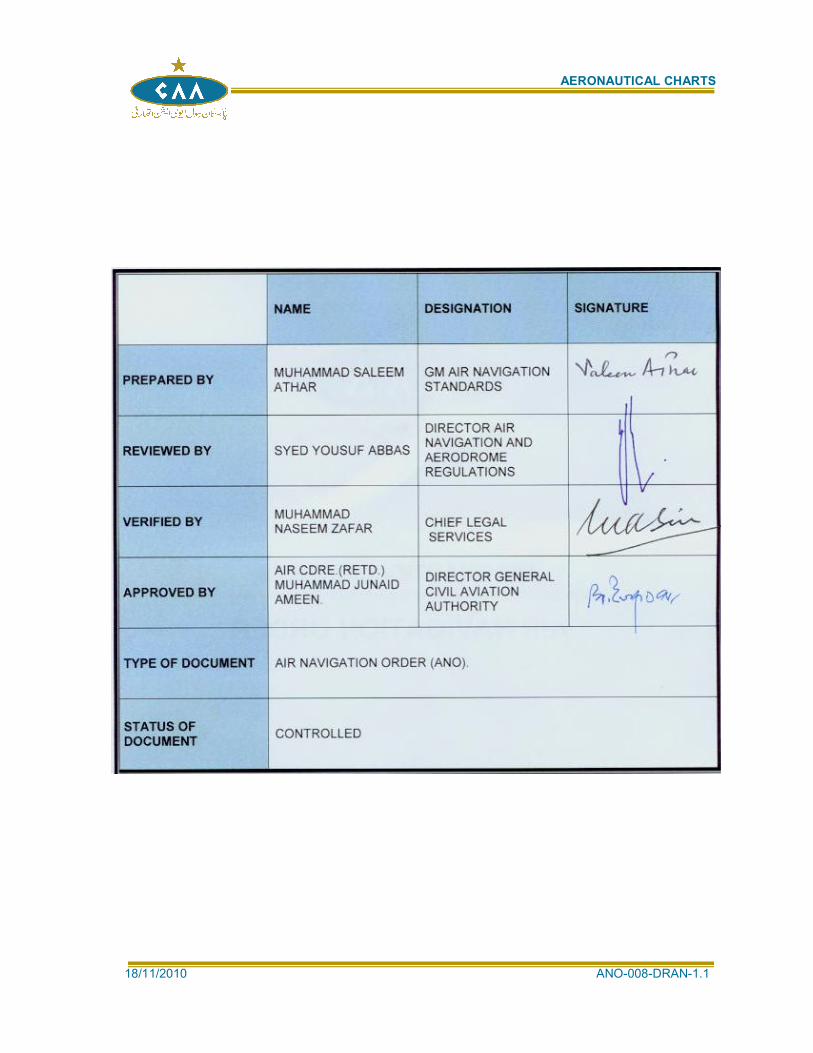
NAME DESIGNATION SIGNATURE
PREPARED BY MUHAMMAD SALEEM ATHAR
GM AIR NAVIGATION STANDARDS
REVIEWED BY SYED YOUSUF ABBAS
DIRECTOR AIR NAVIGATION AND AERODROME REGULATIONS
VERIFIED BY MUHAMMAD NASEEM ZAFAR
CHIEF LEGAL SERVICES
APPROVED BY
AIR CDRE.(RETD.) MUHAMMAD JUNAID AMEEN.
DIRECTOR GENERAL CIVIL AVIATION AUTHORITY
TYPE OF DOCUMENT AIR NAVIGATION ORDER (ANO).
STATUS OF DOCUMENT
CONTROLLED
AERONAUTICAL CHARTS
18/11/2010 ANO-008-DRAN-1.1
RECORDS OF AMENDMENTS
AMENDMENTS
No. Date
Applicable Date Entered Entered by
01 18-11-2010

AERONAUTICAL CHARTS
18/11/2010 ANO-008-DRAN-1.1
INTENTIONALLY
LEFT BLANK
AERONAUTICAL CHARTS
18/11/2010 - i - ANO-008-DRAN-1.1
Table of Contents
A. AUTHORITY: ..................................................................................................................... 1
B. PURPOSE: ......................................................................................................................... 1
C. SCOPE: .............................................................................................................................. 1
D. DESCRIPTION: .................................................................................................................. 1
D1 DEFINITIONS, APPLICABILITY AND AVAILABILITY: ...................................................... 1
D1.1 DEFINITIONS: ................................................................................................................... 1
D1.2 APPLICABILITY: .............................................................................................................. 12
D1.3 AVAILABILITY: ................................................................................................................. 12
D2 GENERAL SPECIFICATIONS: ........................................................................................ 13
D2.1 OPERATIONAL REQUIREMENTS FOR CHARTS: ........................................................ 13
D2.2 TITLES: ............................................................................................................................ 14
D2.3 MISCELLANEOUS INFORMATION: ............................................................................... 14
D2.4 SYMBOLS: ....................................................................................................................... 14
D2.5 UNITS OF MEASUREMENT: .......................................................................................... 15
D2.6 SCALE AND PROJECTION: ........................................................................................... 15
D2.7 DATE OF VALIDITY OF AERONAUTICAL INFORMATION: .......................................... 15
D2.8 SPELLING OF GEOGRAPHICAL NAMES: ..................................................................... 15
D2.9 ABBREVIATIONS: ........................................................................................................... 15
D2.10 POLITICAL BOUNDARIES: ............................................................................................. 16
D2.11 COLOURS: ...................................................................................................................... 16
D2.12 RELIEF: ............................................................................................................................ 16
D2.13 PROHIBITED, RESTRICTED AND DANGER AREAS: ................................................... 16
D2.14 AIR TRAFFIC SERVICES AIRSPACES: ......................................................................... 16
D2.15 MAGNETIC VARIATION: ................................................................................................. 16
D2.16 TYPOGRAPHY: ............................................................................................................... 17
D2.17 AERONAUTICAL DATA: ................................................................................................. 17
D2.18 COMMON REFERENCE SYSTEMS: .............................................................................. 18
D3 AERODROME OBSTACLE CHART — ICAO TYPE A (OPERATING LIMITATIONS): .. 19
D3.1 FUNCTION: ...................................................................................................................... 19
D3.2 AVAILABILITY: ................................................................................................................. 19
D3.3 UNITS OF MEASUREMENT: .......................................................................................... 19
D3.4 COVERAGE AND SCALE: .............................................................................................. 19
D3.5 FORMAT: ......................................................................................................................... 20
D3.6 IDENTIFICATION: ............................................................................................................ 20
D3.7 MAGNETIC VARIATION: ................................................................................................. 20
AERONAUTICAL CHARTS
18/11/2010 - ii - ANO-008-DRAN-1.1
D3.8 AERONAUTICAL DATA: ................................................................................................. 20
D3.9 ACCURACY: .................................................................................................................... 22
D4 AERODROME OBSTACLE CHART — ICAO TYPE B ................................................... 23
D4.1 FUNCTION: ...................................................................................................................... 23
D4.2 AVAILABILITY: ................................................................................................................. 23
D4.3 UNITS OF MEASUREMENT: .......................................................................................... 23
D4.4 COVERAGE AND SCALE: .............................................................................................. 23
D4.5 FORMAT: ......................................................................................................................... 23
D4.6 IDENTIFICATION: ............................................................................................................ 24
D4.7 CULTURE AND TOPOGRAPHY: .................................................................................... 24
D4.8 MAGNETIC VARIATION: ................................................................................................. 24
D4.9 AERONAUTICAL DATA: ................................................................................................. 24
D4.10 ACCURACY: .................................................................................................................... 25
D5 AERODROME TERRAIN AND OBSTACLE CHART — ICAO (ELECTRONIC): ............ 26
D5.1 FUNCTION: ...................................................................................................................... 26
D5.2 AVAILABILITY: ................................................................................................................. 26
D5.3 IDENTIFICATION: ............................................................................................................ 27
D5.4 CHART COVERAGE: ...................................................................................................... 27
D5.5 CHART CONTENT: ......................................................................................................... 27
D5.6 ACCURACY AND RESOLUTION: ................................................................................... 29
D5.7 ELECTRONIC FUNCTIONALITY: ................................................................................... 29
D5.8 CHART DATA PRODUCT SPECIFICATIONS: ............................................................... 30
D6 PRECISION APPROACH TERRAIN CHART — ICAO ................................................... 31
D6.1 FUNCTION: ...................................................................................................................... 31
D6.2 AVAILABILITY: ................................................................................................................. 31
D6.3 SCALE: ............................................................................................................................ 31
D6.4 IDENTIFICATION: ............................................................................................................ 31
D6.5 PLAN AND PROFILE INFORMATION: ........................................................................... 31
D7 ENROUTE CHART — ICAO ............................................................................................ 31
D7.1 FUNCTION: ...................................................................................................................... 31
D7.2 AVAILABILITY: ................................................................................................................. 32
D7.3 COVERAGE AND SCALE: .............................................................................................. 32
D7.4 PROJECTION: ................................................................................................................. 32
D7.5 IDENTIFICATION: ............................................................................................................ 32
D7.6 CULTURE AND TOPOGRAPHY: .................................................................................... 32
D7.7 MAGNETIC VARIATION: ................................................................................................. 33
D7.8 BEARINGS, TRACKS AND RADIALS: ............................................................................ 33
D7.9 AERONAUTICAL DATA: ................................................................................................. 33
AERONAUTICAL CHARTS
18/11/2010 - iii - ANO-008-DRAN-1.1
D8 AREA CHART — ICAO ................................................................................................... 35
D8.1 FUNCTION: ...................................................................................................................... 35
D8.2 AVAILABILITY: ................................................................................................................. 35
D8.3 COVERAGE AND SCALE: .............................................................................................. 35
D8.4 PROJECTION: ................................................................................................................. 35
D8.5 IDENTIFICATION: ............................................................................................................ 35
D8.6 CULTURE AND TOPOGRAPHY: .................................................................................... 36
D8.7 MAGNETIC VARIATION: ................................................................................................. 36
D8.8 BEARINGS, TRACKS AND RADIALS: ............................................................................ 36
D8.9 AERONAUTICAL DATA: ................................................................................................. 36
D9 STANDARD DEPARTURE CHART — INSTRUMENT (SID) — ICAO ........................... 38
D9.1 FUNCTION: ...................................................................................................................... 38
D9.2 AVAILABILITY: ................................................................................................................. 38
D9.3 COVERAGE AND SCALE: .............................................................................................. 38
D9.4 PROJECTION: ................................................................................................................. 38
D9.5 IDENTIFICATION: ............................................................................................................ 39
D9.6 CULTURE AND TOPOGRAPHY: .................................................................................... 39
D9.7 MAGNETIC VARIATION: ................................................................................................. 39
D9.8 BEARINGS, TRACKS AND RADIALS: ............................................................................ 39
D9.9 AERONAUTICAL DATA: ................................................................................................. 40
D10 STANDARD ARRIVAL CHART — INSTRUMENT (STAR) — ICAO .............................. 42
D10.1 FUNCTION: ...................................................................................................................... 42
D10.2 AVAILABILITY: ................................................................................................................. 42
D10.3 COVERAGE AND SCALE: .............................................................................................. 42
D10.4 PROJECTION: ................................................................................................................. 42
D10.5 IDENTIFICATION: ............................................................................................................ 42
D10.6 CULTURE AND TOPOGRAPHY: .................................................................................... 43
D10.7 MAGNETIC VARIATION: ................................................................................................. 43
D10.8 BEARINGS, TRACKS AND RADIALS: ............................................................................ 43
D10.9 AERONAUTICAL DATA: ................................................................................................. 43
D11 INSTRUMENT APPROACH CHART — ICAO ................................................................ 45
D11.1 FUNCTION: ...................................................................................................................... 45
D11.2 AVAILABILITY: ................................................................................................................. 46
D11.3 COVERAGE AND SCALE: .............................................................................................. 46
D11.4 FORMAT: ......................................................................................................................... 46
D11.5 PROJECTION: ................................................................................................................. 46
D11.6 IDENTIFICATION: ............................................................................................................ 46
D11.7 CULTURE AND TOPOGRAPHY: .................................................................................... 47
AERONAUTICAL CHARTS
18/11/2010 - iv - ANO-008-DRAN-1.1
D11.8 MAGNETIC VARIATION: ................................................................................................. 47
D11.9 BEARINGS, TRACKS AND RADIALS: ............................................................................ 47
D11.10 AERONAUTICAL DATA: ................................................................................................. 48
D12 VISUAL APPROACH CHART — ICAO ........................................................................... 51
D12.1 FUNCTION: ...................................................................................................................... 51
D12.2 AVAILABILITY: ................................................................................................................. 51
D12.3 SCALE: ............................................................................................................................ 52
D12.4 FORMAT: ......................................................................................................................... 52
D12.5 PROJECTION: ................................................................................................................. 52
D12.6 IDENTIFICATION: ............................................................................................................ 52
D12.7 CULTURE AND TOPOGRAPHY: .................................................................................... 52
D12.8 MAGNETIC VARIATION: ................................................................................................. 52
D12.9 BEARINGS, TRACKS AND RADIALS: ............................................................................ 53
D12.10 AERONAUTICAL DATA: ................................................................................................. 53
D13 AERODROME/HELIPORT CHART — ICAO................................................................... 54
D13.1 FUNCTION: ...................................................................................................................... 54
D13.2 AVAILABILITY: ................................................................................................................. 54
D13.3 COVERAGE AND SCALE: .............................................................................................. 54
D13.4 IDENTIFICATION: ............................................................................................................ 54
D13.5 MAGNETIC VARIATION: ................................................................................................. 54
D13.6 AERODROME/HELIPORT DATA: ................................................................................... 54
D14 AERODROME GROUND MOVEMENT CHART — ICAO ............................................... 56
D14.1 FUNCTION: ...................................................................................................................... 56
D14.2 AVAILABILITY: ................................................................................................................. 57
D14.3 COVERAGE AND SCALE: .............................................................................................. 57
D14.4 IDENTIFICATION: ............................................................................................................ 57
D14.5 MAGNETIC VARIATION: ................................................................................................. 57
D14.6 AERODROME DATA: ...................................................................................................... 57
D15 AIRCRAFT PARKING/DOCKING CHART — ICAO ........................................................ 58
D15.1 FUNCTION: ...................................................................................................................... 58
D15.2 AVAILABILITY: ................................................................................................................. 58
D15.3 COVERAGE AND SCALE: .............................................................................................. 58
D15.4 IDENTIFICATION: ............................................................................................................ 58
D15.5 MAGNETIC VARIATION: ................................................................................................. 58
D15.6 AERODROME DATA: ...................................................................................................... 58
D16 WORLD AERONAUTICAL CHART — ICAO 1:1 000 000............................................... 59
D16.1 FUNCTION: ...................................................................................................................... 59
D16.2 AVAILABILITY: ................................................................................................................. 59
AERONAUTICAL CHARTS
18/11/2010 - v - ANO-008-DRAN-1.1
D16.3 SCALES: .......................................................................................................................... 60
D16.4 FORMAT: ......................................................................................................................... 60
D16.5 PROJECTION: ................................................................................................................. 60
D16.6 IDENTIFICATION: ............................................................................................................ 61
D16.7 CULTURE AND TOPOGRAPHY: .................................................................................... 62
D16.8 MAGNETIC VARIATION: ................................................................................................. 64
D16.9 AERONAUTICAL DATA: ................................................................................................. 64
D17 AERONAUTICAL CHART — ICAO 1:500 000 ................................................................ 65
D17.1 FUNCTION: ...................................................................................................................... 65
D17.2 AVAILABILITY: ................................................................................................................. 65
D17.3 SCALES: .......................................................................................................................... 65
D17.4 FORMAT: ......................................................................................................................... 66
D17.5 PROJECTION: ................................................................................................................. 66
D17.6 IDENTIFICATION: ............................................................................................................ 66
D17.7 CULTURE AND TOPOGRAPHY: .................................................................................... 67
D17.8 MAGNETIC VARIATION: ................................................................................................. 69
D17.9 AERONAUTICAL DATA: ................................................................................................. 69
D18 AERONAUTICAL NAVIGATION CHART — ICAO SMALL SCALE ................................ 70
D18.1 FUNCTION: ...................................................................................................................... 70
D18.2 AVAILABILITY: ................................................................................................................. 70
D18.3 COVERAGE AND SCALE: .............................................................................................. 70
D18.4 FORMAT: ......................................................................................................................... 71
D18.5 PROJECTION: ................................................................................................................. 71
D18.6 CULTURE AND TOPOGRAPHY: .................................................................................... 71
D18.7 MAGNETIC VARIATION: ................................................................................................. 73
D18.8 AERONAUTICAL DATA: ................................................................................................. 73
D19 PLOTTING CHART — ICAO ........................................................................................... 74
D19.1 FUNCTION: ...................................................................................................................... 74
D19.2 AVAILABILITY .................................................................................................................. 74
D19.3 COVERAGE AND SCALE: .............................................................................................. 74
D19.4 FORMAT: ......................................................................................................................... 74
D19.5 PROJECTION: ................................................................................................................. 74
D19.6 IDENTIFICATION: ............................................................................................................ 75
D19.7 CULTURE AND TOPOGRAPHY: .................................................................................... 75
D19.8 MAGNETIC VARIATION: ................................................................................................. 75
D19.9 AERONAUTICAL DATA: ................................................................................................. 75
D20 ELECTRONIC AERONAUTICAL CHART DISPLAY — ICAO......................................... 76
D20.1 FUNCTION: ...................................................................................................................... 76
AERONAUTICAL CHARTS
18/11/2010 - vi - ANO-008-DRAN-1.1
D20.2 INFORMATION AVAILABLE FOR DISPLAY: ................................................................. 76
D20.3 DISPLAY REQUIREMENTS: ........................................................................................... 76
D20.4 PROVISION AND UPDATING OF DATA: ....................................................................... 77
D20.5 PERFORMANCE TESTS, MALFUNCTION ALARMS AND INDICATIONS: .................. 77
D20.6 BACK-UP ARRANGEMENTS: ......................................................................................... 77
D21 ATC SURVEILLANCE MINIMUM ALTITUDE CHART — ICAO ...................................... 78
D21.1 FUNCTION: ...................................................................................................................... 78
D21.2 AVAILABILITY: ................................................................................................................. 78
D21.3 COVERAGE AND SCALE: .............................................................................................. 78
D21.4 PROJECTION: ................................................................................................................. 78
D21.5 IDENTIFICATION: ............................................................................................................ 78
D21.6 CULTURE AND TOPOGRAPHY: .................................................................................... 79
D21.7 MAGNETIC VARIATION: ................................................................................................. 79
D21.8 BEARINGS, TRACKS AND RADIALS: ............................................................................ 79
D21.9 AERONAUTICAL DATA: ................................................................................................. 79
E. EVIDENCES (ACRONYMS / RECORDS / REFERENCES): .......................................... 80
E1 ACRONYMS .................................................................................................................... 80
E2 RECORDS ....................................................................................................................... 84
E3 REFERENCES: ................................................................................................................ 84
IMPLEMENTATION: ............................................................................................................................ 84
APPENDIX – 1 MARGINAL NOTE LAYOUT ............................................................................... 85
APPENDIX 2 ICAO CHART SYMBOLS ................................................................................... 86
APPENDIX 3 COLOUR GUIDE ................................................................................................ 99
APPENDIX 4 HYPSOMETRIC TINT GUIDE .......................................................................... 101
APPENDIX 5 SHEET LAYOUT INDEX FOR THE WORLD AERONAUTICAL CHART — ICAO 1:1 000 000 ........................................................................... 102
APPENDIX 6 AERONAUTICAL DATA QUALITY REQUIREMENTS ..................................... 103
AERONAUTICAL CHARTS
18/11/2010 Page 1 of 106 ANO-008-DRAN-1.1
A. AUTHORITY:
A1 This Air Navigation Order (ANO) has been issued by the Director General of Pakistan Civil Aviation Authority in pursuance of Rules 4 (3), 180, 360 and other enabling provisions of the Civil Aviation Rules, 1994 (CARs, 94).
B. PURPOSE:
B1 To provide the specifications for physical characteristics, configuration, material, performance, personnel or procedure pertaining to the provision of authentic and accurate Aeronautical Charts to the extent possible, the uniform application of which is recognized as necessary and/or desirable for the safety and regularity of air navigation in Islamic Republic of Pakistan and to ensure compliance of Civil Aviation Rules, 1994 and ICAO SARPS prescribed in Annex-4 & other related documents.
C. SCOPE:
C1 The specifications prescribed in this ANO shall be applicable to all Air Navigation Service Providers, Operators, Meteorological Authority, Civil/Technical Works and other agencies which collect, prepare, check, compile, disseminate and receive aeronautical charts for Air Navigation purposes.
D. DESCRIPTION:
D1 DEFINITIONS, APPLICABILITY AND AVAILABILITY:
D1.1 DEFINITIONS:
The following terms when used in this ANO, have the meanings assigned to them respectively. Any term not defined are used hereunder, shall have the same meaning as given in Civil Aviation Ordinance 1960, Pakistan Civil Aviation Authority Ordinance, 1982 and CARs, 1994.
D1.1.1 AERODROME: Any area of land or water designed, equipped, set apart or commonly used or intended to be
used, either wholly or in part, for affording facilities for the landing and departure, of aircraft and includes all buildings, sheds, vessels, piers, and other structures thereon or appertaining thereto.
Note:- The term “aerodrome” where used in the provisions relating to flight plans and ATS messages is intended to cover also sites other than aerodromes which may be used by certain types of aircraft, e.g. helicopters or balloons.
D1.1.2 AERODROME ELEVATION: The elevation of the highest point of the landing area.
D1.1.3 AERODROME OPERATING MINIMA: The cloud ceiling and visibility, or runway visual range, for take-off; and the decision
height, or altitude, or minimum descent height, or altitude, and visibility, or runway, visual range, and visual reference, for landing; specified by an operator in his operations manual as being the minima for take-off and landing by an aircraft at an aerodrome. In other words it is the limits of usability of an aerodrome for:
a) take-off, expressed in terms of runway visual range and/or visibility and, if necessary, cloud conditions;
b) landing in precision approach and landing operations, expressed in terms of visibility and/or runway visual range and decision altitude/height (DA/H) as appropriate to the category of the operation; and
c) landing in approach and landing operations with vertical guidance, expressed in terms of visibility and/or runway visual range and decision altitude/height (DA/H); and
d) landing in non-precision approach and landing operations, expressed in terms of visibility and/or runway visual range, minimum descent altitude/height (MDA/H) and,
AERONAUTICAL CHARTS
18/11/2010 Page 2 of 106 ANO-008-DRAN-1.1
if necessary, cloud conditions.
D1.1.4 AERODROME REFERENCE POINT: The designated geographical location of an aerodrome.
D1.1.5 AERONAUTICAL CHART: A representation of a portion of the Earth, its culture and relief, specifically designated to
meet the requirements of air navigation. Aircraft stand. A designated area on an apron intended to be used for parking an aircraft.
D1.1.6 AIRCRAFT STAND: A designated area on an apron intended to be used for parking an aircraft.
D1.1.7 AIR DEFENCE IDENTIFICATION ZONE: Special designated airspace of defined dimensions within which aircraft are required to
comply with special identification and/or reporting procedures additional to those related to the provision of air traffic services (ATS).
D1.1.8 Deleted
D1.1.9 AIR TRAFFIC SERVICE: A generic term meaning variously, flight information service, alerting service, air traffic
advisory service, air traffic control service (area control service, approach control service or aerodrome control service).
D1.1.10 AIR TRANSIT ROUTE: A defined route for the air transiting of helicopters.
D1.1.11 AIRWAY: An area designated by the Director-General as an airway under rule 67 and which is a
control area in the form of a corridor equipped with radio navigational aids.
D1.1.12 ALTITUDE: The vertical distance in feet of a level or a point, or an object considered as a point,
measured from mean sea level (MSL).
D1.1.13 APPLICATION: Manipulation and processing of data in support of user requirements (ISO 19104*).
D1.1.14 APRON: That part of an aerodrome to be used:
a) for the purpose of enabling passenger to board, or disembarked from, aircraft
b) for loading cargo on to, or unloading cargo from, aircraft, or
c) for refuelling, parking or carrying out maintenance on aircraft.
(A defined area, on a land aerodrome, intended to accommodate aircraft for purposes of loading or unloading passengers, mail or cargo, fuelling, parking or maintenance.)
D1.1.15 AREA MINIMUM ALTITUDE (AMA): The minimum altitude to be used under instrument meteorological conditions (IMC) that
will provide a minimum obstacle clearance within a specified area, normally formed by parallels and meridians.
D1.1.16 AREA NAVIGATION (RNAV): A method of navigation which permits aircraft operation on any desired flight path within the coverage of ground-or space-based navigation aids or within the limits of the capability of self-contained aids, or a combination of these.
AERONAUTICAL CHARTS
18/11/2010 Page 3 of 106 ANO-008-DRAN-1.1
Note: - Area navigation includes performance-based navigation as well as other operations that do not meet the definition of performance-based navigation.
D1.1.17 ARRIVAL ROUTES: Routes identified in an instrument approach procedure by which aircraft may proceed
from the en-route phase of flight to an initial approach fix.
D1.1.18 ATS ROUTE: A specified route designed for channeling the flow of traffic as necessary for the
provision of air traffic services.
Note 1:- The term ATS route is used to mean variously, airway, advisory route, controlled or uncontrolled route, arrival or departure route, etc.
Note 2:- An ATS route is defined by route specifications that include an ATS route designator, the track to or from significant points (waypoints), distance between significant points, reporting requirements and, as determined by the appropriate ATS authority, the lowest safe altitude.
D1.1.19 ATS SURVEILLANCE SYSTEM: A generic term meaning variously, ADS-B, PSR, SSR or any comparable ground-based
system that enables the identification of aircraft.
D1.1.20 BARE EARTH: Surface of the Earth including bodies of water and permanent ice and snow, and
excluding vegetation and man-made objects.
D1.1.21 CALENDAR: Discrete temporal reference system that provides the basis for defining temporal position
to a resolution of one day (ISO 19108*).
D1.1.22 CANOPY: Bare Earth supplemented by vegetation height.
D1.1.23 CHANGE-OVER POINT: The point at which an aircraft navigating on an ATS route segment defined by reference
to very high frequency omnidirectional radio ranges is expected to transfer its primary navigational reference from the facility behind the aircraft to the next facility ahead of the aircraft.
Note:- Change-over points are established to provide the optimum balance in respect of signal strength and quality between facilities at all levels to be used and to ensure a common source of azimuth guidance for all aircraft operating along the same portion of a route segment.
D1.1.24 CLEARWAY: A defined rectangular area on the ground or water under the control of the appropriate
authority, selected or prepared as a suitable area over which an aeroplane may make a portion of its initial climb to a specified height.
D1.1.25 CONTOUR LINE: A line on a map or chart connecting points of equal elevation.
D1.1.26 CULTURE: All man-made features constructed on the surface of the Earth, such as cities, railways
and canals.
D1.1.27 CYCLIC REDUNDANCY CHECK (CRC): A mathematical algorithm applied to the digital expression of data that provides a level of
assurance against loss or alteration of data.
AERONAUTICAL CHARTS
18/11/2010 Page 4 of 106 ANO-008-DRAN-1.1
D1.1.28 DANGER AREA: An airspace of defined dimensions within which activities dangerous to the flight of
aircraft may exist at specified times.
D1.1.29 DATA PRODUCT SPECIFICATION: Detailed description of a data set or data set series together with additional information
that will enable it to be created, supplied to and used by another party (ISO 19131).
Note:- A data product specification provides a description of the universe of discourse and a specification for mapping the universe of discourse to a data set. It may be used for production, sales, end-use or other purpose.
D1.1.30 DATA QUALITY: A degree or level of confidence that the data provided meet the requirements of the data
user in terms of accuracy, resolution and integrity.
D1.1.31 DATA SET: Identical collection of data (ISO19101).
D1.1.32 DATA SET SERIES: Collection of data sets sharing the same product specification (ISO 191 15*).
D1.1.33 DATUM: Any quantity or set of quantities that may serve as a reference or basis for the calculation
of other quantities (ISO 19104).
D1.1.34 DIGITAL ELEVATION MODEL (DEM): The representation of terrain surface by continuous elevation vales at all intersections of
a defined grid, referenced to common datum.
D1.1.35 DISPLACED THRESHOLD: A threshold not located at the extremity of a runway.
D1.1.36 ELECTRONIC AERONAUTICAL CHART DISPLAY: An electronic device by which flight crews are enabled to execute, in a convenient and
timely manner, route planning, route monitoring and navigation by displaying required information.
D1.1.37 ELEVATION: The vertical distance of a point or a level, on or affixed to the surface of the earth,
measured from mean sea level.
D1.1.38 ELLIPSOID HEIGHT (GEODETIC HEIGHT): The height related to the reference ellipsoid, measured along the ellipsoidal outer normal
through the point in question.
D1.1.39 FEATURE: Abstraction of real world phenomena (ISO 19101).
D1.1.40 FEATURE ATTRIBUTE: Characteristic of a feature (ISO 19101).
Note:- A feature attribute has a name, a data type and a value domain associated with it.
D1.1.41 FINAL APPROACH: That part of an instrument approach procedure which commences at the specified final
approach fix or point, or where such a fix or point is not specified,
a) at the end of the last procedure turn, base turn or inbound turn of a racetrack procedure, if specified; or
AERONAUTICAL CHARTS
18/11/2010 Page 5 of 106 ANO-008-DRAN-1.1
b) at the point of interception of the last track specified in the approach procedure; and
ends at a point in the vicinity of an aerodrome from which:
i. a landing can be made; or
ii. a missed approach procedure is initiated.
D1.1.42 FINAL APPROACH AND TAKE-OFF AREA (FATO): A defined area over which the final phase of the approach manoeuvre to hover or landing
is completed and from which the take-off manoeuvre is commenced. Where the FATO is to be used by performance Class 1 helicopters, the defined area includes the rejected take-off area available.
D1.1.43 FINAL APPROACH FIX OR POINT: That fix or point of an instrument approach procedure where the final approach segment
commences.
D1.1.44 FINAL APPROACH SEGMENT: That segment of an instrument approach procedure in which alignment and descent for
landing are accomplished.
D1.1.45 FLIGHT INFORMATION REGION: An airspace designated as a flight information region by the director general under the rule 67
and which is an airspace in which flight information and alerting services are available.
D1.1.46 FLIGHT LEVEL: A surface of constant atmospheric pressure which is related to a specific pressure
datum, 1 013.2 hectopascals (hPa), and is separated from other such surfaces by specific pressure intervals.
Note 1:- A pressure type altimeter calibrated in accordance with the Standard Atmosphere:
a) when set to a QNH altimeter setting, will indicate altitude;
b) when set to a QFE altimeter setting, will indicate height above the QFE reference datum;
c) when set to a pressure of 1 013.2 hPa, may be used to indicate flight levels.
Note 2:- The terms “height” and “altitude”, used in Note 1 above, indicate altimetric rather than geometric heights and altitudes.
D1.1.47 GEODESIC DISTANCE: The shortest distance between any two points on a mathematically defined ellipsoidal
surface.
D1.1.48 GEODETIC DATUM: A minimum set of parameters required to define location and orientation of the local
reference system with respect to the global reference system/frame.
D1.1.49 GEOID: The equipotential surface in the gravity field of the Earth which coincides with the
undisturbed mean sea level (MSL) extended continuously through the continents.
Note:- The geoid is irregular in shape because of local gravitational disturbances (wind tides, salinity, current, etc.) and the direction of gravity is perpendicular to the geoid at every point.
AERONAUTICAL CHARTS
18/11/2010 Page 6 of 106 ANO-008-DRAN-1.1
D1.1.50 GEOID UNDULATION: The distance of the geoid above (positive) or below (negative) the mathematical
reference ellipsoid.
Note:- In respect to the World Geodetic System — 1984 (WGS-84) defined ellipsoid, the difference between the WGS-84 ellipsoidal height and orthometric height represents WGS-84 geoid undulation.
D1.1.51 GLIDE PATH: A descent profile determined for vertical guidance during a final approach.
D1.1.52 GREGORIAN CALENDAR: Calendar in general use; first introduced in 1582 to define a year that more closely
approximates the tropical year than the Julian calendar (ISO 19 108).
Note:- In the Gregorian calendar, common years have 365 days and leap years 366 days divided into twelve sequential months.
D1.1.53 HEIGHT: The vertical distance of a level, a point or an object considered as a point, measured
from a specified datum.
D1.1.54 HELICOPTER STAND: An aircraft stand which provides for parking a helicopter and where ground taxi
operations are completed or where the helicopter touches down and lifts off for air taxi operations.
D1.1.55 HELIPORT: An aerodrome or a defined area on a structure intended to be used wholly or in part for
the arrival, departure and surface movement of helicopters.
D1.1.56 HOLDING PROCEDURE: A predetermined manoeuvre which keeps an aircraft within a specified airspace while
awaiting further clearance.
D1.1.57 HOT SPOT: A location on an aerodrome movement area with a history or potential risk of collision or
runway incursion, and where heightened attention by pilots/drivers is necessary.
D1.1.58 HUMAN FACTORS PRINCIPLES: Principles which apply to aeronautical design, certification, training, operations and
maintenance and which seek safe interface between the human and other system components by proper consideration to human performance.
D1.1.59 HYPSOMETRIC TINTS: A succession of shades or colour gradations used to depict ranges of elevation.
D1.1.60 INITIAL APPROACH SEGMENT: That segment of an instrument approach procedure between the initial approach fix and
the intermediate approach fix or, where applicable, the final approach fixes or point.
D1.1.61 INSTRUMENT APPROACH PROCEDURE: A series of predetermined manoeuvres by reference to flight instruments with specified
protection from obstacles from the initial approach fix, or where applicable, from the beginning of a defined arrival route to a point from which a landing can be completed and thereafter, if a landing is not completed, to a position at which holding or en-route obstacle clearance criteria apply.
D1.1.62 INTERMEDIATE APPROACH SEGMENT: That segment of an instrument approach procedure between either the intermediate
approach fix and the final approach fix or point, or between the end of a reversal, racetrack or dead reckoning track procedure and the final approach fix or point, as appropriate.
AERONAUTICAL CHARTS
18/11/2010 Page 7 of 106 ANO-008-DRAN-1.1
D1.1.63 INTERMEDIATE HOLDING POSITION: A designated position intended for traffic control at which taxiing aircraft and vehicles
shall stop and hold until further cleared to proceed, when so instructed by the aerodrome control tower.
D1.1.64 ISOGONAL: A line on a map or chart on which all points have the same magnetic variation for a
specified epoch.
D1.1.65 ISOGRIV: A line on a map or chart which joins points of equal angular difference between the North
of the navigation grid and Magnetic North.
D1.1.66 LANDING AREA: That part of a movement area intended for the landing or take-off of aircraft.
D1.1.67 LANDING DIRECTION INDICATOR: A device to indicate visually the direction currently designated for landing and for take-
off.
D1.1.68 LEVEL: A generic term relating to the vertical position of an aircraft in flight and meaning
variously, height, altitude or flight level.
D1.1.69 LOGON ADDRESS: A specified code used for data link logon to an ATS unit.
D1.1.70 MAGNETIC VARIATION: The angular difference between True North and Magnetic North.
Note:- The value given indicates whether the angular difference is East or West of True North .
D1.1.71 MANOEUVRING AREA: The part of an aerodrome to be used for the take-off and landing of aircraft and for the
movement of aircraft associated with take-off and landing, excluding aprons.
D1.1.72 MARKING: A symbol or group of symbols displayed on the surface of the movement area in order to
convey aeronautical information.
D1.1.73 METADATA: Data about data (ISO 19115).
Note:- Data that describes and documents data.
D1.1.74 MINIMUM EN-ROUTE ALTITUDE (MEA): The altitude for an en-route segment that provides adequate reception of relevant
navigation facilities and ATS communications. Complies with the airspace structure and provides the required obstacle clearance.
D1.1.75 MINIMUM OBSTACLE CLEARANCE ALTITUDE (MOCA): The minimum altitude for a defined segment of flight that provides the required obstacle
clearance.
D1.1.76 MINIMUM SECTOR ALTITUDE: The lowest altitude which may be used which will provide a minimum clearance of 300 m
(1 000 ft) above all objects located in an area contained within a sector of a circle of 46 km (25 NM) radius centred on a radio aid to navigation.
AERONAUTICAL CHARTS
18/11/2010 Page 8 of 106 ANO-008-DRAN-1.1
D1.1.77 MISSED APPROACH POINT (MAPT): That point in an instrument approach procedure at or before which the prescribed missed
approach procedure must be initiated in order to ensure that the minimum obstacle clearance is not infringed.
D1.1.78 MISSED APPROACH PROCEDURE: The procedure to be followed if the approach cannot be continued.
D1.1.79 MOVEMENT AREA: That part of an aerodrome to be used for the take-off, landing and taxiing of aircraft,
consisting of the manoeuvring area and the apron(s).
D1.1.80 NAVIGATION SPECIFICATION: A set of aircraft and flight crew requirements needed to support performance-based
navigation operations within a defined airspace. There are two kinds of navigation specifications:
D1.1.80.1 REQUIRED NAVIGATION PERFORMANCE (RNP) SPECIFICATION:. A navigation specification based on area navigation that includes the requirement for
performance monitoring and alerting, designated by the prefix RNP, e.g. RNP 4, RNP APCH.
D1.1.80.2 AREA NAVIGATION (RNAV) SPECIFICATION: A navigation specification based on area navigation that does not include the
requirement for performance monitoring and alerting, designated by the prefix RNAV, e.g. RNAV 5, RNAV 1.
Note:- The ICAO Performance-Based Navigation Manual(Doc 9613),Volume II contains detailed guidance on navigation specifications.
Note:- The term RNP as previously defined as “a statement of the navigation performance ,necessary for operation within a defined airspace” ,has been removed from this ANO as the concept of RNP has been overtaken by the concept of PBN. The term RNP in this ANO is now solely used in context of navigation specifications that require performance monitoring and alerting. E.g. RNP 4 refers to the aircraft and operating requirements including a 4NMlateral performance with on board performance monitoring and alerting that are detailed in the PBN Manual (Doc9613).
D1.1.81 OBSTACLE: All fixed (whether temporary or permanent) and mobile objects, or parts thereof, that:
a) are located on an area intended for the surface movement of aircraft; or
b) extend above a defined surface intended to protect aircraft in flight; or
c) stand outside those defined surfaces and that have been assessed as being a hazard to air navigation.
Note:- The term obstacle is used in this ANO solely for the purpose of specifying the charting of objects that are considered a potential hazard to the safe passage of aircraft in the type of operation for which the individual chart series is designed.
D1.1.82 OBSTACLE CLEARANCE ALTITUDE (OCA) OR OBSTACLE CLEARANCE HEIGHT (OCH):
The lowest altitude or the lowest height above the elevation of the relevant runway threshold or the aerodrome elevation as applicable, used in establishing compliance with appropriate obstacle clearance criteria.
Note 1:- Obstacle clearance altitude is referenced to mean sea level and obstacle clearance height is referenced to the threshold elevation or in the case of non-precision approaches to the aerodrome elevation or the threshold elevation if that is more than 2 m
AERONAUTICAL CHARTS
18/11/2010 Page 9 of 106 ANO-008-DRAN-1.1
(7 ft) below the aerodrome elevation. An obstacle clearance height for a circling approach is referenced to the aerodrome elevation.
Note 2:- For convenience when both expressions are used they may be written in the form “obstacle clearance altitude/height” and abbreviated “OCA/H”.
Note 3:- See Procedures for Air Navigation Services — Aircraft Operations (Doc 8168), Volume I, Part III, 1.5, and Volume II, Part III, 6.4, for specific applications of this definition.
D1.1.83 OBSTACLE FREE ZONE (OFZ): The airspace above the inner approach surface, inner transitional surfaces, and balked
landing surface and that portion of the strip bounded by these surfaces, which is not penetrated by any fixed obstacle other than a low-mass and frangibly mounted one required for air navigation purposes.
D1.1.84 OPERATOR: A person, organization, or enterprise engaged in, or offering to engage in, an aircraft
operation.
D1.1.85 ORTHOMETRIC HEIGHT: Height of a point related to the geoid, generally presented as an MSL elevation.
D1.1.86 PERFORMANCE BASED NAVIGATION (PBN): Area navigation based on performance requirements for aircraft operating along an
ATS route, on an instrument approach procedure or in a designated airspace.
Note:- Performance requirements are expressed in navigation specifications (RNAV specification, RNP specification) in terms of accuracy, integrity, continuity, availability and functionality needed for the proposed operation in the context of a particular airspace concept.
D1.1.87 POINT LIGHT: A luminous signal appearing without perceptible length.
D1.1.88 PORTRAYAL: Presentation of information to humans(ISO 19117)
D1.1.89 POSITION (GEOGRAPHICAL): Set of coordinates (latitude and longitude) referenced to the mathematical reference
ellipsoid which define the position of a point on the surface of the Earth.
D1.1.90 PRECISION APPROACH PROCEDURE: An instrument approach procedure utilizing azimuth and glide path information provided
by ILS or PAR.
D1.1.91 PROCEDURE ALTITUDE/HEIGHT: A specified altitude/height flown operationally at or above the minimum altitude/height
and established to accommodate a stabilized descent at a prescribed descent gradient/angle in the intermediate/final approach segment.
D1.1.92 PROCEDURE TURN: A manoeuvre in which a turn is made away from a designated track followed by a turn in
the opposite direction to permit the aircraft to intercept and proceed along the reciprocal of the designated track.
Note 1:- Procedure turns are designated “left” or “right” according to the direction of the initial turn.
Note 2:- Procedure turns may be designated as being made either in level flight or while descending, according to the circumstances of each individual procedure.
AERONAUTICAL CHARTS
18/11/2010 Page 10 of 106 ANO-008-DRAN-1.1
D1.1.93 PROHIBITED AREA: An area designated by the Director-General under Rule 67 to be a prohibited area (An
airspace of defined dimensions, above the land areas or territorial waters, within which the flight of aircraft is prohibited).
D1.1.94 RELIEF: The inequalities in elevation of the surface of the Earth represented on aeronautical
charts by contours, hypsometric tints, shading or spot elevations.
D1.1.95 REPORTING POINT: A specified (named) geographical location in relation to which the position of an aircraft
can be reported.
Note;- There are three categories of reporting points: ground-based navigation aid, intersection and waypoint. In this context of this definition ,intersection is a significant point expressed as radials, bearings and /or distances from ground-based navigation aids. A reporting point can be indicated as “on request “ or as “ compulsory “
D1.1.96 RESOLUTION: A number of units or digits to which a measured or calculated value is expressed and
used.
D1.1.97 RESTRICTED AREA: An area designated by the Director-General under Rule 67 to be a restricted area (An
airspace of defined dimensions, above the land areas or territorial waters of a State, within which the flight of aircraft is restricted in accordance with certain specified conditions).
D1.1.98 REVERSAL PROCEDURE: A procedure designed to enable aircraft to reverse direction during the initial approach
segment of an instrument approach procedure. The sequence may include procedure turns or base turns.
D1.1.99 RUNWAY: A defined rectangular area on a land aerodrome prepared for the landing and take-off of
aircraft.
D1.1.100 RUNWAY-HOLDING POSITION: A designated position intended to protect a runway, an obstacle limitation surface, or an
ILS/MLS critical/sensitive area at which taxiing aircraft and vehicles shall stop and hold, unless otherwise authorized by the aerodrome control tower.
D1.1.101 RUNWAY STRIP: A defined area including the runway and stopway, if provided:
a) intended :to reduce the risk of damage to aircraft running off a runway; and
b) to protect aircraft flying over it during take-off or landing operations.
D1.1.102 RUNWAY VISUAL RANGE (RVR): The range over which the pilot of an aircraft on the centre line of a runway can see the
runway surface markings or the lights delineating the runway or identifying its centre line.
D1.1.103 SHOULDER: An area adjacent to the edge of a pavement so prepared as to provide a transition
between the pavement and the adjacent surface.
D1.1.104 SIGNIFICANT POINT: A specified geographical location used in defining an ATS route or the flight path of an aircraft and for other navigation and ATS purposes.
AERONAUTICAL CHARTS
18/11/2010 Page 11 of 106 ANO-008-DRAN-1.1
Note:- There are three categories of significant points: ground-based navigation aid, intersection and waypoint. In the context of this definition, intersection is a significant point expressed as radials, bearings and/or distances from ground-based navigation aids.
D1.1.105 STOP-WAY: A defined rectangular area on the ground at the end of take-off run available prepared as
a suitable area in which an aircraft can be stopped in the case of an abandoned take-off.
D1.1.106 TAXIING: Movement of an aircraft on the surface of an aerodrome under its own power, excluding
take-off and landing, but including, in the case of helicopters, operation over the surface of an aerodrome within a height band associated with ground effect and at speeds associated with taxiing.
D1.1.107 TAXI-ROUTE: A defined path established for the movement of helicopters from one part of a heliport to
another. A taxi-route includes a helicopter air or ground taxiway which is centred on the taxi-route.
D1.1.108 TAXIWAY: A defined path on a land aerodrome established for the taxiing of aircraft and intended to
provide a link between one part of the aerodrome and another, including:
a) AIRCRAFT STAND TAXI LANE. A portion of an apron designated as a taxiway and
intended to provide access to aircraft stands only;
b) APRON TAXIWAY. A portion of a taxiway system located on an apron and intended
to provide a through taxi route across the apron;
c) RAPID EXIT TAXIWAY. A taxiway connected to a runway at an acute angle and designed to allow landing aeroplanes to turn off at higher speeds than are achieved on other exit taxiways thereby minimizing runway occupancy times.
D1.1.109 TERMINAL ARRIVAL ALTITUDE (TAA): The lowest altitude that will provide a minimum clearance of 300 m (1 000 ft) above all
objects located in an arc of a circle defined by a 46-km (25 NM) radius centred on the initial approach fix (IAF), or where there is no IAF on the intermediate approach fix (IF), delimited by straight lines joining the extremity of the arc to the IF. The combined TAAs associated with an approach procedure shall account for an area of 360 degrees around the IF.
D1.1.110 TERRAIN: The surface of the Earth containing naturally occurring features such as mountains, hills,
ridges, valleys, bodies of water, permanent ice and snow, and excluding obstacles.
Note:- In practical terms, depending on the method of data collection, terrain represents the continuous surface that exists at the bare Earth, the top of the canopy or something in-between, also known as “first reflective surface” .
D1.1.111 THRESHOLD: The beginning of that portion of the runway usable for landing.
D1.1.112 TOUCHDOWN AND LIFT-OFF AREA (TLOF): A load bearing area on which a helicopter may touch down or lift off.
D1.1.113 TOUCHDOWN ZONE: The portion of a runway, beyond the threshold, where it is intended landing aeroplanes
first contact the runway.
D1.1.114 TRACK: The projection on the earth’s surface of the path of an aircraft, the direction of which path at
any point is usually expressed in degrees from North (true, magnetic or grid).
AERONAUTICAL CHARTS
18/11/2010 Page 12 of 106 ANO-008-DRAN-1.1
D1.1.115 TRANSITION ALTITUDE: The altitude at or below which the vertical position of an aircraft is controlled by reference
to altitudes.
D1.1.116 VECTORING: Provision of navigational guidance to aircraft in the form of specific headings, based on
the use of an ATS surveillance system.
D1.1.117 VISUAL APPROACH PROCEDURE: A series of predetermined manoeuvres by visual reference, from the initial approach fix,
or where applicable, from the beginning of a defined arrival route to a point from which a landing can be completed and thereafter, if a landing is not completed, a go-around procedure can be carried out.
D1.1.118 WAYPOINT: A specified geographical location used to define an area navigation route or the flight path
of an aircraft employing area navigation. Waypoints are identified as either:
a) FLY-BY WAYPOINT:
A waypoint which requires turn anticipation to allow tangential interception of the next segment of a route or procedure; or
b) FLYOVER WAYPOINT: A waypoint at which a turn is initiated in order to join the next segment of a route or procedure.
D1.2 APPLICABILITY:
D1.2.1 The specifications of this ANO shall be applicable to all aeronautical charts with effect from 15th November, 2009.
D1.2.2 AIS providers shall ensure that aeronautical charts conform to the prescribed (specifications) as far as practicable.
D1.2.2.1 All charts should in addition conform to the recommended practices relevant to the particular chart.
D1.3 AVAILABILITY:
D1.3.1 Information: The Authority (AIS Provider) shall on request by another Contracting State provide all the information relating to its own territory that is necessary to enable the standards of this ANO to be met.
D1.3.2 Charts: The Authority (AIS Provider) shall, when so specified, ensure the availability of charts in whichever of the following ways is appropriate for a particular chart or single sheet of a chart series.
D1.3.2.1 For any chart or single sheet of a chart series entirely contained within the territory of Pakistan, having the jurisdiction over the territory shall either:
a) produce the chart or sheet itself; or
b) arrange for its production by another Contracting State or by an agency; or
c) provide another Contracting State prepared to accept an obligation to produce the chart or sheet with the data necessary for its production.
D1.3.2.2 For any chart or single sheet of a chart series which includes the territory of two or more Contracting States, the States having jurisdiction over the territory so included shall determine the manner in which the chart or sheet will be made available. This determination shall be made with due regard being given to regional air navigation agreements and to any programme of allocation established by the Council of ICAO.
AERONAUTICAL CHARTS
18/11/2010 Page 13 of 106 ANO-008-DRAN-1.1
Note:- The phrase “regional air navigation agreements” refers to the agreements approved by the Council of ICAO normally on the advice of regional air navigation meetings.
D1.3.3 The Authority (AIS Provider) shall take all reasonable measures to ensure that the information it provides and the aeronautical charts made available are adequate and accurate and that they are maintained up to date by an adequate revision service.
D1.3.4 To improve worldwide dissemination of information on new charting techniques and production methods, appropriate charts produced by the Authority should be made available without charge to other Contracting States on request on a reciprocal basis.
Note:- Guidance material on the preparation of aeronautical charts, including sample formats, is contained in the Aeronautical Chart Manual (Doc 8697).
D2 GENERAL SPECIFICATIONS:
Note:- The standards and recommended practices contained in this Para are applicable
to all ICAO aeronautical charts unless otherwise stated in the specifications of the chart concerned.
D2.1 OPERATIONAL REQUIREMENTS FOR CHARTS:
Note:- For the purpose of this ANO, the total flight is divided into the following phases:
Phase 1 - Taxi from aircraft stand to take-off point.
Phase 2 - Take-off and climb to en-route ATS route structure.
Phase 3 - En-route ATS route structure.
Phase 4 - Descent to approach.
Phase 5 - Approach to land missed approach.
Phase 6 - Landing and taxi to aircraft stand.
D2.1.1 Each type of chart shall provide information relevant to the function of the chart and its design shall observe Human Factors principles, which facilitate its optimum use.
Note:- Guidance material on the application of Human Factors principals is available in the ICAO Human Factors Training Manual (Doc. 9683)
D2.1.2 Each type of chart shall provide information appropriate to the phase of flight, to ensure the safe and expeditious operation of the aircraft.
D2.1.3 The presentation of information shall be accurate, free from distortion and clutter, unambiguous, and be readable under all normal operating conditions.
D2.1.4 Colours or tints and type size used shall be such that the chart can be easily read and interpreted by the pilot in varying conditions of natural and artificial light.
D2.1.5 The information shall be in a form, which enables the pilot to acquire it in a reasonable time consistent with workload and operating conditions.
D2.1.6 The presentation of information provided on each type of chart shall permit smooth transition from chart to chart as appropriate to the phase of flight.
D2.1.7 The charts should be True North orientated.
AERONAUTICAL CHARTS
18/11/2010 Page 14 of 106 ANO-008-DRAN-1.1
D2.1.8 The basic sheet size of the charts should be 210 X 148 mm (8.27 X 5.82 in) (A5).
D2.2 TITLES:
D2.2.1 The title of a chart or chart series prepared in accordance with the specifications contained in this ANO and intended to satisfy the function of the chart, shall be that of the relevant Para heading as modified by application of any Standard contained therein, except that such title shall not include “ICAO” unless the chart conforms with all standards specified in D2 and any specified for the particular chart.
D2.3 MISCELLANEOUS INFORMATION:
D2.3.1 The marginal note layout shall be as given in Appendix 1, except as otherwise specified for a particular chart.
D2.3.2 The following information shall be shown on the face of the each chart unless otherwise stated in the specification of the chart concerned:
a) designation or title of the chart series;
Note:- The title may be abbreviated.
b) name and reference of the sheet;
c) on each margin an indication of the adjoining sheet (when applicable).
D2.3.3 A legend to the symbols and abbreviations used shall be provided. The legend shall be on the face or reverse of each chart except that, where it is impracticable for reasons of space, a legend may be published separately.
D2.3.4 The name and adequate address of the producing Authority (agency) shall be shown in the margin of the chart except that, where the chart is published as part of an aeronautical document, this information may be placed in the front of that document.
D2.4 SYMBOLS:
D2.4.1 Symbols used shall conform to those shown in Appendix 2 – ICAO Chart, except that where it is desired to show on an aeronautical chart special features or items of importance to civil aviation for which no ICAO symbol is at present provided, any appropriate symbol may be chosen for this purpose, provided that it does not cause confusion with any existing ICAO chart symbol or impair the legibility of the chart.
Note:- The size and prominence of symbols and the thickness and spacing of lines may be varied according to the scale and functions of the chart, with due regard to the importance of the information they convey.
D2.4.2 To represent ground-based navigation aids, intersections and waypoints, the same basic symbol shall be used on all charts on which they appear, regardless of chart purpose.
D2.4.3 The symbol used for significant points shall be based on a hierarchy of symbols and selected in the following order: ground-based navigation aid, intersection, waypoint symbol. A waypoint symbol shall be used only when a particular significant point does not already exist as either a ground-based navigation aid or intersection.
D2.4.4 The Authority/AIS provider shall ensure that as of 15 November 2012, symbols are shown in the manner specified in D2.4.2, D2.4.3 and Appendix 2 – ICAO Chart Symbols, symbol number 121.
D2.4.5 The Authority/AIS provider should ensure that symbols are shown in the manner specified in D2.4.2, D2.4.3 and Appendix 2 – ICAO Chart Symbols, symbol number 121.

AERONAUTICAL CHARTS
18/11/2010 Page 15 of 106 ANO-008-DRAN-1.1
D2.5 UNITS OF MEASUREMENT:
D2.5.1 Distance shall be derived as geodesic distances.
D2.5.2 Distance shall be expressed either kilometers or nautical miles or both, provided the units are clearly differentiated.
D2.5.3 Altitudes, elevations and heights shall be expressed in either metres or feet or both, provided the units are clearly differentiated.
D2.5.4 Linear dimensions on aerodromes and short distances shall be expressed in metres.
D2.5.5 The order of resolution of distances, dimensions, elevations and heights shall be that as specified for a particular chart.
D2.5.6 The units of measurement used to express distances, altitudes, elevations and heights shall be conspicuously stated on the face of each chart.
D2.5.7 Conversion scales (kilometres/nautical miles, metres/feet) shall be provided on each chart on which distances, elevations or altitudes are shown. The conversion scales shall be placed on the face of each chart.
D2.6 SCALE AND PROJECTION:
D2.6.1 For charts of large areas, the name and basic parameters and scale of the projection shall be indicated.
D2.6.2 For charts of small areas, a linear scale only shall be indicated.
D2.7 DATE OF VALIDITY OF AERONAUTICAL INFORMATION:
D2.7.1 The date of validity of aeronautical information shall be clearly indicated on the face of each chart.
D2.8 SPELLING OF GEOGRAPHICAL NAMES:
D2.8.1 The symbols of the Roman alphabet shall be used for all writing.
D2.8.2 The names of places and of geographical features in countries which officially use varieties of the Roman alphabet shall be accepted in their official spelling, including the accents and diacritical marks used in the respective alphabets.
D2.8.3 Where a geographical term such as “cape”, “point”, “gulf”, “river”, is abbreviated on any particular chart, that word shall be spelt out in full in the English language, in respect of the most important example of each type. Punctuation marks shall not be used in abbreviations within the body of a chart.
D2.8.4 In areas where Romanized names have not been officially produced or adopted, and outside the territory of Contracting Stated, names should be transliterated from the non-Roman alphabet form by the system generally used by the aeronautical charts producing agency/section.
D2.9 ABBREVIATIONS:
D2.9.1 Abbreviations shall be used on aeronautical charts whenever they are appropriate.
D2.9.2 Where applicable, abbreviations should be selected from the Procedures for Air Navigation Services ABC – ICAO Abbreviations and Codes (Doc 8400).
AERONAUTICAL CHARTS
18/11/2010 Page 16 of 106 ANO-008-DRAN-1.1
D2.10 POLITICAL BOUNDARIES:
D2.10.1 International boundaries shall be shown, but may be interrupted if data more important to the use of the chart would be obscured.
D2.10.2 Where the territory of more than one State appears on a chart, the names identifying the countries shall be indicated.
Note:- In the case of a dependent territory, the name of the sovereign State may be added in brackets.
D2.11 COLOURS:
D2.11.1 Colours used on charts should conform to Appendix 3 – Colour Guide.
D2.12 RELIEF:
D2.12.1 Relief, where shown, shall be portrayed in a manner that will satisfy the chart users' need for:
a) orientation and identification;
b) safe terrain clearance;
c) clarity of aeronautical information when shown;
d) planning.
Note:- Relief is usually portrayed by combinations of contours, hypsometric tints, spot elevations and hill shading, the choice of method being affected by the nature and scale of the chart and its intended use.
D2.12.2 Where relief is shown by hypsometric tints, the tints used should be based on those shown in the Hypsometric Tint Guide in Appendix 4.
D2.12.3 Where spot elevations are used they shall be shown for selected critical points.
D2.12.3.1 The value of spot elevations of doubtful accuracy shall be followed by the sign ±.
D2.13 PROHIBITED, RESTRICTED AND DANGER AREAS:
D2.13.1 When prohibited, restricted or danger areas are shown, the reference or other identification shall be included, except that the nationality letters may be omitted.
D2.14 AIR TRAFFIC SERVICES AIRSPACES:
D2.14.1 When ATS airspace is shown on a chart, the class of airspace, the type, name or call sign, the vertical limits and the radio frequency(ies) to be used shall be indicated and the horizontal limits depicted in accordance with Appendix 2 -ICAO Chart Symbols.
D2.14.2 On charts used for visual flight, those parts of the ATS Airspace Classifications table D2.1 given in ANO-002-DRAN-1.0 applicable to the airspace depicted on the chart should be on the face or reverse of each chart.
D2.15 MAGNETIC VARIATION:
D2.15.1 True North and magnetic variation shall be indicated. The order of resolution of magnetic variation shall be that as specified for a particular chart.
AERONAUTICAL CHARTS
18/11/2010 Page 17 of 106 ANO-008-DRAN-1.1
D2.15.2 When magnetic variation is shown on a chart, the values shown should be those for the year nearest to the date of publication that is divisible by five (5), i.e. 1980, 1985, etc. In exceptional cases where the current value would be more than one degree different, after applying the calculation for annual change, an interim date and value should be quoted.
Note:- The date and the annual change may be shown.
D2.15.3 For instrument procedure charts, the publication of a magnetic variation change should be completed within a maximum of six AIRAC cycles.
D2.15.4 In large terminal areas with multiple aerodromes, a single rounded value of magnetic variation should be applied so that the procedures that service multiple aerodromes use a single, common variation value.
D2.16 TYPOGRAPHY:
D2.16.1 The sample types suitable for aeronautical charts prescribed in the ICAO Aeronautical Chart Manual (Doc 8697) should be used.
D2.17 AERONAUTICAL DATA:
D2.17.1 The Authority/AIS Provider shall take all necessary measures to introduce a properly organized quality system containing procedures, processes and resources necessary to implement quality management at each function stage as prescribed in Para D3.1.7 of ANO-007-DRAN-2.0. The execution of such quality management shall be made demonstrable for each function stage, when required. In addition, it shall be ensured that established procedures exist in order that aeronautical data at any moment is traceable to its origin so to allow any data anomalies or errors, detected during the production/maintenance phases or in the operational use, to be corrected.
Note 1:- Specifications governing the quality system are prescribed in Para D3 of ANO007-DRAN-1.0.
Note 2:- Quality system should be implemented by 15 November, 2012 to comply with the above provision.
D2.17.2 The Authority/AIS Provider shall ensure that the order of chart resolution of aeronautical data shall be that as specified for a particular chart and as presented in a tabular form in Appendix 6.
D2.17.3 The Authority /AIS Provider shall ensure that integrity of aeronautical data is maintained throughout the data process from survey/origin to the next intended user. Aeronautical data integrity requirements shall be based upon the potential risk resulting from the corruption of data and upon the use to which the data item is put. Consequently, the following classification and data integrity level shall apply:
a) critical data, integrity level 1 x 10⁻⁸ : there is a high probability when using corrupted critical data that the continued safe flight and landing of an aircraft would be severely at risk with the potential for catastrophe;
b) essential data, integrity level 1 x 10⁻⁵ : there is a low probability when using corrupted essential data that the continued safe flight and landing of an aircraft would be severely at risk with the potential for catastrophe; and
c) routine data, integrity level 1 x 10⁻³ : there is a very low probability when using corrupted routine data that the continued safe flight and landing of an aircraft would be severely at risk with the potential for catastrophe.
D2.17.4 Aeronautical data quality requirements related to the integrity and data classification shall be as provided in Tables 1 to 6 in Appendix 6.
AERONAUTICAL CHARTS
18/11/2010 Page 18 of 106 ANO-008-DRAN-1.1
D2.17.5 Electronic aeronautical data sets shall be protected by the inclusion in the data sets of a 32 bit cyclic redundancy check (CRC) implemented by the application dealing with the data sets. This shall apply to the protection of all integrity levels of data sets as specified in D2.17.3.
Note 1:- Guidance material on the aeronautical data quality requirements (accuracy, resolution, integrity, protection and traceability) is contained in the World Geodetic System — 1984 (WGS-84) Manual (Doc 9674). Supporting material in respect of the provisions of Appendix 6 related to chart resolution and integrity of aeronautical data is contained in RTCA Document DO-201A and European Organization for Civil Aviation Equipment (EUROCAE) Document ED-77 — Industry Requirements for Aeronautical Information
Note 2:- Cyclic Redundancy Check (CRC) shall be implemented by 15 November, 2012 to comply with the provisions of Para D2.17.5.
D2.18 COMMON REFERENCE SYSTEMS:
D2.18.1 HORIZONTAL REFERENCE SYSTEM:
D2.18.1.1 World Geodetic System -- 1984 (WGS-84) shall be used as the horizontal (geodetic) reference system. Published aeronautical geographical coordinates (indicating latitude and longitude) shall be expressed in terms of the WGS-84 geodetic reference datum.
Note:- Comprehensive guidance material concerning WGS-84 is contained in the World Geodetic System — 1984 (WGS-84) Manual (Doc 9674).
D2.18.1.2 Geographical coordinates which have been transformed into WGS-84 coordinates but whose accuracy of original field work does not meet the requirements prescribed in Para D2 of ANO-002-DRAN-1.0,and ICAO Annex 14, Volumes I and II, chapter 2 shall be identified by an asterisk.
D2.18.1.3 The order of chart resolution of geographical coordinates shall be that specified for a particular chart series and in accordance with Appendix 6, Table 1.
Note:- Specifications governing the determination and reporting (accuracy of filed work and data integrity) of WGS-84 related aeronautical coordinates for geographical positions established by air traffic services are given in ANO-002-DRAN-1.0 Para D2, D11 Table D11.1; and for aerodromes/heliport related positions are given in Annex 14, Volumes I and II, Chapter 2, and in Table 2 of Appendices 5 and 1, respectively.
D2.18.2 VERTICAL REFERENCE SYSTEM:
D2.18.2.1 Mean sea level (MSL) datum, which gives the relationship of gravity-related height (elevation) to a surface known as the geoid, shall be used as the vertical reference system.
Note 1:- The geoid globally most closely approximates MSL. It is defined as the equipotential surface in the gravity field of the Earth that coincides with the undisturbed MSL extended continuously through the continents.
Note 2:- Gravity-related heights (elevations) are also referred to as orthometric heights while distances of points above the ellipsoid are referred to as ellipsoidal heights.
D2.18.2.2 In addition to the elevations referenced to MSL, for the specific surveyed ground positions, geoid undulation (referenced to the WGS-84 ellipsoid) for those positions shall also be published as specified for a particular chart.
Note:- Specifications governing the determination and reporting (accuracy of filed work and data integrity) of elevation and geoid undulation at specific positions at aerodromes/heliports are given in Annex 14, Volumes I and II, Chapter 2, and in Table 2 of Appendices 5 and 1, respectively.
AERONAUTICAL CHARTS
18/11/2010 Page 19 of 106 ANO-008-DRAN-1.1
Note:- AIS Authority should prepare plan for the implementation of geoid undulation as the same has not been implemented yet in Pakistan and the provision shall be implemented latest by 12 November 2015.
D2.18.2.3 The order of chart resolution of elevation and geoid undulation shall be that specified for a particular chart series and in accordance with Appendix 6, Table 2.
D2.18.3 TEMPORAL REFERENCE SYSTEM:
D2.18.3.1 The Gregorian calendar and Coordinated Universal Time (UTC) shall be used as the temporal reference system.
D2.18.3.2 When a different temporal reference system is used for charting, this shall be indicated in GEN 2.1.2 of the Aeronautical Information Publication (AIP).
D3 AERODROME OBSTACLE CHART — ICAO TYPE A (OPERATING LIMITATIONS):
D3.1 FUNCTION:
D3.1.1 This chart, in combination with the relevant information published in the AIP, shall provide the data necessary to enable an operator to comply with the operating limitations of Annex 6, Part I, Chapter 5, and Part III, Section II, Chapter 3.
D3.2 AVAILABILITY:
D3.2.1 Aerodrome Obstacle Charts — ICAO Type A (Operating Limitations) shall be made available in the manner prescribed in D1.3.2 for all aerodromes regularly used by international civil aviation, except for those aerodromes where there are no obstacles in the take-off flight path areas or where the Aerodrome Terrain and Obstacle Chart — ICAO (Electronic) is provided in accordance with provisions of Para D5.
D3.2.2 Where a chart is not required because no obstacles exist in the take-off flight path area, a notification to this effect shall be published in the AIP.
D3.3 UNITS OF MEASUREMENT:
D3.3.1 Elevations shall be shown to the nearest half-metre or to the nearest foot.
D3.3.2 Linear dimensions shall be shown to the nearest half-metre.
D3.4 COVERAGE AND SCALE:
D3.4.1 The extent of each plan shall be sufficient to cover all obstacles.
Note:- Isolated distant obstacles that would unnecessarily increase the sheet size may be indicated by the appropriate symbol and an arrow, provided that the distance and bearing from the end of the runway farthest removed and the elevation are given.
D3.4.2 The horizontal scale shall be within the range of 1:10 000 to 1:15 000.
D3.4.3 The horizontal scale should be 1:10 000.
Note:- When the production of the charts would be expedited thereby, a scale
of 1:20 000 may be used.
AERONAUTICAL CHARTS
18/11/2010 Page 20 of 106 ANO-008-DRAN-1.1
D3.4.4 The vertical scale shall be ten times the horizontal scale.
D3.4.5 Linear scale:
D3.4.5.1 Horizontal and vertical linear scales showing both metres and feet shall be included in the charts.
D3.5 FORMAT:
D3.5.1 The charts shall depict a plan and profile of each runway, any associated stopway or clearway, the take-off flight path area and obstacles.
D3.5.2 The profile for each runway, stopway, clearway and the obstacles in the take-off flight path area shall be shown above its corresponding plan. The profile of an alternative take-off flight path area shall comprise a linear projection of the full take-off flight path and shall be disposed above its corresponding plan in the manner most suited to the ready interpretation of the information.
D3.5.3 A profile grid shall be ruled over the entire profile area exclusive of the runway. The zero for vertical coordinates shall be mean sea level. The zero for horizontal coordinates shall be the end of the runway furthest from the take-off flight path area concerned. Graduation marks indicating the subdivisions of intervals shall be shown along the base of the grid and along the vertical margins.
D3.5.3.1 The vertical grid should have intervals of 30 m (100 ft) and the horizontal grid should have intervals of 300 m (1 000 ft).
D3.5.4 The chart shall include:
a) a box for recording the operational data specified in Para D3.8.3;
b) a box for recording amendments and dates thereof.
D3.6 IDENTIFICATION:
D3.6.1 The chart shall be identified by the country’s name (i.e. Pakistan), the name of the city or town, or area, which the aerodrome serves, the name of the aerodrome and the designator(s) of the runway(s).
D3.7 MAGNETIC VARIATION:
D3.7.1 The magnetic variation to the nearest degree and date of information shall be indicated.
D3.8 AERONAUTICAL DATA:
D3.8.1 Obstacles:
D3.8.1.1 Objects in the take-off flight path area which project above a plane surface having a 1.2 per cent slope and having a common origin with the take-off flight path area, shall be regarded as obstacles, except that obstacles lying wholly below the shadow of other obstacles as defined in Para D3.8.1.2 need not be shown. Mobile objects such as boats, trains and trucks, which may project above the 1.2 per cent plane, shall be considered obstacles but shall not be considered as being capable of creating a shadow.
D3.8.1.2 The shadow of an obstacle is considered to be a plane surface originating at a horizontal line passing through the top of the obstacle at right angles to the centre line of the take-off flight path area. The plane covers the complete width of the take-off flight path area and extends to the plane defined in Para D3.8.1.1 or to the next higher obstacle if it occurs first. For the first 300 m (1 000 ft) of the take-off flight path area, the shadow planes are horizontal and beyond this point such planes have an upward slope of 1.2 per cent.
AERONAUTICAL CHARTS
18/11/2010 Page 21 of 106 ANO-008-DRAN-1.1
D3.8.1.3 If the obstacle creating a shadow is likely to be removed, objects that would become obstacles by its removal shall be shown.
D3.8.2 Take-off flight path area:
D3.8.2.1 The take-off flight path area consists of a quadrilateral area on the surface of the earth lying directly below, and symmetrically disposed about, the take-off flight path. This area has the following characteristics:
a) it commences at the end of the area declared suitable for take-off (i.e. at the end of the runway or clearway as appropriate);
b) its width at the point of origin is 180 m (600 ft) and this width increases at the rate of 0.25D to a maximum of 1 800 m (6 000 ft), where D is the distance from the point of origin;
c) it extends to the point beyond which no obstacles exist or to a distance of 10.0 km (5.4 NM), whichever is the lesser.
D3.8.2.2 For runways serving aircraft having operating limitations which do not preclude the use of a take-off flight path gradient of less than 1.2 per cent, the extent of the takeoff flight path area specified in Para D3.8.2.1 c) shall be increased to not less than 12.0 km (6.5 NM) and the slope of the plane surface specified in Para D3.8.1.1 and D3.8.1.2 shall be reduced to 1.0 per cent or less.
Note:- When a 1.0 per cent survey plane touches no obstacles, this plane may be lowered until it touches the first obstacle.
D3.8.3 Declared distances:
D3.8.3.1 The following information for each direction of each runway shall be entered in the space provided:
a) take-off run available;
b) accelerate-stop distance available;
c) take-off distance available;
d) landing distance available.
Note:- In Annex 14, Volume I, Attachment A, Section 3, guidance is given on declared distances.
D3.8.3.2 Where a declared distance is not provided because a runway is usable in one direction only, that runway should be identified as “not usable for takeoff, landing or both”.
D3.8.4 Plan and profile views:
D3.8.4.1 The plan view shall show:
a) the outline of the runways by a solid line, including the length and width, the magnetic bearing to the nearest degree, and the runway number;
b) the outline of the clearways by a broken line, including the length and identification as such;
c) take-off flight path areas by a dashed line and the centre line by a fine line consisting of short and long dashes;
AERONAUTICAL CHARTS
18/11/2010 Page 22 of 106 ANO-008-DRAN-1.1
d) alternative take-off flight path areas. When alternative take-off flight path areas not centred on the extension of the runway centre line are shown, notes shall be provided explaining the significance of such areas;
e) obstacles, including:
i. the exact location of each obstacle together with a symbol indicative of its type;
ii. the elevation and identification of each obstacle;
iii. the limits of penetration of obstacles of large extent in a distinctive manner identified in the legend.
Note:- This does not exclude the necessity for indicating critical spot elevations within the take-off flight path area.
D3.8.4.1.1 The nature of the runway and stopway surfaces should be indicated.
D3.8.4.1.2 Stopways should be identified as such and should be shown by a broken line.
D3.8.4.1.3 When stopways are shown, the length of each stopway shall be indicated.
D3.8.4.2 The profile view shall show:
a) the profile of the centre line of the runway by a solid line and the profile of the centre line of any associated stopways and clearways by a broken line;
b) the elevation of the runway centre line at each end of the runway, at the stopway and at the origin of each takeoff flight path area, and at each significant change in slope of runway and stopway;
c) obstacles, including:
i. each obstacle by a solid vertical line extending from a convenient grid line over at least one other grid line to the elevation of the top of the obstacle;
ii. identification of each obstacle;
iii. the limits of penetration of obstacles of large extent in a distinctive manner identified in the legend.
Note:- An obstacle profile consisting of a line joining the tops of each obstacle and representing the shadow created by successive obstacles may be shown.
D3.9 ACCURACY:
D3.9.1 The order of accuracy attained shall be shown on the chart.
D3.9.2 The horizontal dimensions and the elevations of the runway, stopway and clearway to be printed on the chart should be determined to the nearest 0.5 m (1 ft).
D3.9.3 The order of accuracy of the field work and the precision of chart production should be such that measurements in the take-off flight path areas can be taken from the chart within the following maximum deviations:
a) horizontal distances: 5 m (15 ft) at a point of origin increasing at a rate of 1 per 500;
b) vertical distances: 0.5 m (1.5 ft) in the first 300 m (1 000 ft) and increasing at a rate of 1 per 1 000.
AERONAUTICAL CHARTS
18/11/2010 Page 23 of 106 ANO-008-DRAN-1.1
D3.9.4 Datum:
D3.9.4.1 Where no accurate datum for vertical reference is available, the elevation of the datum used shall be stated and shall be identified as assumed.
D4 AERODROME OBSTACLE CHART — ICAO TYPE B
D4.1 FUNCTION:
D4.1.1 This chart shall provide information to satisfy the following functions:
a) the determination of minimum safe altitudes/heights including those for circling procedures;
b) the determination of procedures for use in the event of an emergency during take-off or landing;
c) the application of obstacle clearing and marking criteria; and
d) the provision of source material for aeronautical charts.
D4.2 AVAILABILITY:
D4.2.1 Aerodrome Obstacle Charts — ICAO Type B should be made available, in the manner prescribed in Para D1.3.2, for all aerodromes regularly used by international civil aviation except for those aerodromes where the Aerodrome Terrain and Obstacle Chart — ICAO (Electronic) is provided in accordance with Para D5.
D4.2.2 When a chart combining the specifications prescribed in Para D3 and D4 is made available, it shall be called the Aerodrome Obstacle Chart — ICAO (Comprehensive).
D4.3 UNITS OF MEASUREMENT:
D4.3.1 Elevations shall be shown to the nearest half-metre or to the nearest foot.
D4.3.2 Linear dimensions shall be shown to the nearest half-metre.
D4.4 COVERAGE AND SCALE:
D4.4.1 The extent of each plan shall be sufficient to cover all obstacles.
Note:- Isolated distant obstacles that would unnecessarily increase the sheet size may be indicated by the appropriate symbol and an arrow, provided that the distance and bearing from the aerodrome reference point and elevation are given.
D4.4.2 The horizontal scale shall be within the range of 1:10 000 to 1:20 000.
D4.4.3 A horizontal linear scale showing both metres and feet shall be included in the chart. When necessary, a linear scale for kilometres and a linear scale for nautical miles shall also be shown.
D4.5 FORMAT:
D4.5.1 The charts shall include:
a) any necessary explanation of the projection used;
b) any necessary identification of the grid used;
AERONAUTICAL CHARTS
18/11/2010 Page 24 of 106 ANO-008-DRAN-1.1
c) a notation indicating that obstacles are those which penetrate the surfaces specified in Annex 14, Volume I, Chapter 4;
d) a box for recording amendments and dates thereof;
e) outside the neat line, every minute of latitude and longitude marked in degrees and minutes.
Note:- Lines of latitude and longitude may be shown across the face of the chart.
D4.6 IDENTIFICATION:
D4.6.1 The chart shall be identified by the country’s name (i.e. Pakistan), the name of the city or town, or area, which the aerodrome serves and the name of the aerodrome.
D4.7 CULTURE AND TOPOGRAPHY:
D4.7.1 Drainage and hydrographic details shall be kept to a minimum.
D4.7.2 Buildings and other salient features associated with the aerodrome shall be shown. Wherever possible, they shall be shown to scale.
D4.7.3 All objects, either cultural or natural, that project above the take-off and approach surfaces specified in D4.9 or the clearing and marking surfaces specified in Annex 14, Volume I, Chapter 4, shall be shown.
D4.7.4 Roads and railroads within the take-off and approach area, and less than 600 m (2 000 ft) from the end of the runway or runway extensions, shall be shown.
Note:- Geographical names of features may be shown if of significance.
D4.8 MAGNETIC VARIATION:
D4.8.1 The chart shall show a compass rose orientated to the True North, or a North point, showing the magnetic variation to the nearest degree with the date of magnetic information and annual change.
D4.9 AERONAUTICAL DATA:
D4.9.1 The charts shall show:
a) the aerodrome reference point and its geographical coordinates in degrees, minutes and seconds;
b) the outline of the runways by a solid line;
c) the length and width of the runway;
d) the magnetic bearing to the nearest degree of the runway and the runway number;
e) the elevation of the runway centre line at each end of the runway, at the stopway, at the origin of each takeoff and approach area, and at each significant change of slope of runway and stopway;
f) taxiways, aprons and parking areas identified as such, and the outlines by a solid line;
g) stopways identified as such and depicted by a broken line;
h) the length of each stopway;
AERONAUTICAL CHARTS
18/11/2010 Page 25 of 106 ANO-008-DRAN-1.1
i) clearways identified as such and depicted by a broken line;
j) the length of each clearway;
k) take-off and approach surfaces identified as such and depicted by a broken line;
l) take-off and approach areas;
Note:- The take-off area is described in D3.8.2.1. The approach area consists of an area on the surface of the earth lying directly below the approach surface as specified in Annex 14, Volume I, Chapter 4.
m) obstacles at their exact location, including:
i. a symbol indicative of their type;
ii. elevation;
iii. identification;
iv. limits of penetration of large extent in a distinctive manner identified in the legend;
Note:- This does not exclude the necessity for indicating critical spot elevations within the take-off and approach areas.
n) any additional obstacles, as determined by D3.8.1.1 including the obstacles in the shadow of an obstacle, which would otherwise be exempted.
Note:- The specifications in Annex 14, Volume I, Chapter 4, are minimum requirements. Where the competent authority has established lower surfaces, they may be used in the determination of obstacles.
D4.9.1.1 The nature of the runway and stopway surfaces should be given.
D4.9.1.2 Wherever practicable, the highest object or obstacle between adjacent approach areas within a radius of 5 000 m (15 000 ft) from the aerodrome reference point should be indicated in a prominent manner.
D4.9.1.3 The extent of tree areas and relief features, part of which constitute obstacles should be shown.
D4.10 ACCURACY:
D4.10.1 The order of accuracy attained shall be shown on the chart.
D4.10.2 The horizontal dimensions and the elevations of the movement area, stopways and clearways to be printed on the chart should be determined to the nearest 0.5 m (1 ft).
D4.10.3 The order or accuracy of the field work and the precision of chart production should be such that the resulting data will be within the maximum deviations indicated herein:
a) Take-off and approach areas:
i. horizontal distances: 5 m (15 ft) at point of origin increasing at a rate of 1 per 500;
ii. vertical distances: 0.5 m (1.5 ft) in the first 300 m (1 000 ft) and increasing at a rate of 1 per 1 000.
AERONAUTICAL CHARTS
18/11/2010 Page 26 of 106 ANO-008-DRAN-1.1
b) Other areas:
i. horizontal distances: 5 m (15 ft) within 5 000 m (15 000 ft) of the aerodrome reference point and 12 m (40 ft) beyond that area;
ii. vertical distances: 1 m (3 ft) within 1 500 m (5 000 ft) of the aerodrome reference point increasing at a rate of 1 per 1 000.
D4.10.4 Datum:
D4.10.4.1 Where no accurate datum for vertical reference is available, the elevation of the datum used shall be stated and identified as assumed.
Note:- PCAA has adopted Aerodrome Obstacle Chart ICAO — Type A. Aerodrome obstacle chart ICAO – Type B is not produced/published.
D5 AERODROME TERRAIN AND OBSTACLE CHART — ICAO (ELECTRONIC):
D5.1 FUNCTION:
D5.1.1 This electronic chart shall portray the terrain and obstacle data in combination with aeronautical data, as appropriate, necessary to:
a) enable an operator to comply with the operating limitations of Annex 6, Part I, Chapter 5, and Part III, Section II, Chapter 3 by developing contingency procedures for use in the event of an emergency during a missed approach or take-off, and by performing aircraft operating limitations analysis; and
b) support the following air navigation applications:
i. instrument procedure design (including circling procedure);
ii. aerodrome obstacle restriction and removal; and
iii. provision of source data for the production of other aeronautical charts.
D5.2 AVAILABILITY:
D5.2.1 From 12 November 2015, Aerodrome Terrain and Obstacle Charts — ICAO (Electronic) shall be made available in the manner prescribed in D1.3.2 for aerodromes regularly used by International Civil Aviation.
Note 1:- Where the Aerodrome Terrain and Obstacle Chart — ICAO (Electronic) is made available, the Aerodrome Obstacle Chart — ICAO Type A (Operating Limitations) and the Aerodrome Obstacle Chart — ICAO Type B are not required (see D3.2.1 and D4.2.1).
Note 2:- The information required by the Precision Approach Terrain Chart — ICAO may be provided in the Aerodrome Terrain and Obstacle Chart — ICAO (Electronic). Where this occurs the Precision Approach Terrain Chart — ICAO is not required (see D6.2.1).
D5.2.2 Aerodrome Terrain and Obstacle Charts — ICAO (Electronic) should be made available in the manner prescribed in D1.3.2 for all aerodromes regularly used by international civil aviation.
D5.2.3 The Aerodrome Terrain and Obstacle Chart — ICAO (Electronic) shall also be made available in hard copy format upon request.
Note:- For specifications regarding hard copy printed output see D5.7.7.
AERONAUTICAL CHARTS
18/11/2010 Page 27 of 106 ANO-008-DRAN-1.1
D5.2.4 The ISO 19100 series of standards for geographic information shall be used as a general data modelling framework.
Note:- The use of the ISO 19100 series of standards for geographic information supports the interchange and use of the Aerodrome Terrain and Obstacle Chart — ICAO (Electronic) among different users.
D5.3 IDENTIFICATION:
D5.3.1 Electronic charts shall be identified by the name of the country (Pakistan) in which the aerodrome is located, the name of the city or town which the aerodrome serves, and the name of the aerodrome.
D5.4 CHART COVERAGE:
D5.4.1 The extent of each chart shall be sufficient to cover Area 2 as specified in Para D10.1 of ANO-007-DRAN-2.0.
D5.5 CHART CONTENT:
D5.5.1 GENERAL:
D5.5.1.1 When developing computer graphic applications that are used to portray features on the chart, the relationships between features, feature attributes, and the underlying spatial geometry and associated topological relationships shall be specified by an application schema. Portrayed information shall be provided on the basis of portrayal specifications applied according to defined portrayal rules. Portrayal specifications and portrayal rules shall not be part of the data set. Portrayal rules shall be stored in a portrayal catalogue which shall make reference to separately-stored portrayal specifications.
Note:- ISO Standard 19117 contains a definition of the schema describing the portrayal mechanism of feature-based geographic information, while ISO Standard 19109 contains rules for application schema. Spatial geometry and associated topological relationships are defined in ISO Standard 19107.
D5.5.1.2 Symbols used to portray features shall be in accordance with Para D2.4 and Appendix 2 — ICAO Chart Symbols.
D5.5.2 TERRAIN FEATURE:
D5.5.2.1 The terrain feature, and associated attributes, to be portrayed and database linked to the chart shall be based on the electronic terrain data sets which satisfy the requirements specified in Para D10 and D12 of ANO-007-DRAN-2.0.
D5.5.2.2 The terrain feature shall be portrayed in a manner that provides an effective general impression of a terrain. This shall be a representation of terrain surface by continuous elevation values at all intersections of the defined grid, also known as the Digital Elevation Model (DEM).
Note:- In accordance with Para D10 and D12 of ANO-007-DRAN-2.0., the DEM for Area 2 post spacing (grid) is specified at 1 arc second (approximately 30 m).
D5.5.2.3 Representation of terrain surface should be provided as a selectable layer of contour lines in addition to the DEM.
D5.5.2.4 An ortho-rectified image which matches the features on the DEM with features on the overlying image should be used to enhance the DEM. The image should be provided as a separate selectable layer.
AERONAUTICAL CHARTS
18/11/2010 Page 28 of 106 ANO-008-DRAN-1.1
D5.5.2.5 The portrayed terrain feature shall be linked to the following associated attributes in the database(s):
a) horizontal positions of grid points in geographic coordinates and elevations of the points;
b) surface type;
c) contour line values, if provided; and
d) names of cities, towns and other prominent topographic features.
D5.5.2.6 Other terrain attributes specified in Para D12 and Table D12-3 of ANO-007-DRAN-2.0 and provided in the database(s) should be linked to the portrayed terrain feature.
D5.5.3 Obstacle features D5.5.3.1 Obstacle features, and associated attributes, portrayed or database-linked to the chart shall be based on electronic obstacle data sets which satisfy the requirements given in Para D10 and D12 of ANO-007-DRAN-2.0.
D5.5.3.1 Each obstacle shall be portrayed by an appropriate symbol and obstacle identifier.
D5.5.3.2 The portrayed obstacle feature shall be linked to the following associated attributes in the database(s):
a) horizontal position in geographic coordinates and associated elevation;
b) obstacle type; and
c) obstacle extent, if appropriate.
D5.5.3.3 Other obstacle attributes specified in D12 and Table D12-3 of ANO-007-DRAN-2.0 and provided in the database(s) should be linked to the portrayed obstacle feature.
D5.5.4 AERODROME FEATURES:
D5.5.4.1 Aerodrome features, and associated attributes, portrayed and database-linked to the chart shall be based on aerodrome data which satisfy the requirements of Annex 14, Volume I, Appendix 5 and Para D11 of ANO-007-DRAN-2.0.
D5.5.4.2 The following aerodrome features shall be portrayed by an appropriate symbol:
a) aerodrome reference point;
b) runway(s), with designation numbers, and if available, stopway(s) and clearway(s); and
c) taxiways, aprons, large buildings and other prominent aerodrome features.
D5.5.4.3 The portrayed aerodrome feature shall be linked to the following associated attributes in the database(s):
a) geographical coordinates of the aerodrome reference point;
b) aerodrome magnetic variation, year of information and annual change;
Note:- Magnetic variation may be database-linked to the aerodrome reference point.
c) length and width of runway(s), stopway(s) and clearway(s);
d) type of surface of runway(s) and stopway(s);
AERONAUTICAL CHARTS
18/11/2010 Page 29 of 106 ANO-008-DRAN-1.1
e) magnetic bearings of the runway(s) to the nearest degree;
f) elevations at each end of runway(s), stopway(s) and clearway(s), and at each significant change in slope of runway(s) and stopway(s);
g) declared distances for each runway direction, or the abbreviation “NU” where a runway direction cannot be used for take-off or landing or both.
Note:- Annex 14, Volume I, Attachment A, provides guidance on declared distances.
D5.5.5 RADIO NAVIGATION AID FEATURES:
D5.5.5.1 Each radio navigation aid feature located within the chart coverage shall be portrayed by an appropriate symbol.
Note:- Navigation aid feature attributes may be linked to the portrayed navigation aid features in the database(s).
D5.6 ACCURACY AND RESOLUTION:
D5.6.1 The order of accuracy of aeronautical data shall be as specified in Para D11 of ANO-002-DRAN-1.0 and Annex 14, Volume I, Appendix 5 and Volume II, Appendix 1. The order of accuracy of terrain and obstacle data shall be as specified in Para D12 of ANO-007-DRAN-2.0.
D5.6.2 The aeronautical data resolution shall be as specified in Para D11 while the resolution for terrain and obstacle data shall be as specified in Para D12 of ANO-007-DRAN-2.0.
D5.7 ELECTRONIC FUNCTIONALITY:
D5.7.1 It shall be possible to vary the scale at which the chart is viewed. Symbols and text size shall vary with chart scale to enhance readability.
D5.7.2 Information on the chart shall be geo-referenced, and it shall be possible to determine cursor position to at least the nearest second.
D5.7.3 The chart shall be compatible with widely available desktop computer hardware, software and media.
D5.7.4 The chart should include its own “reader” software.
D5.7.5 It shall not be possible to remove information from the chart without an authorized update.
D5.7.6 When, due to congestion of information, the details necessary to support the function of the chart cannot be shown with sufficient clarity on a single comprehensive chart view, selectable information layers shall be provided to allow for the customized combination of information.
Note:- An electronic chart format with user-selectable information layers is the preferred
method of presentation for most aerodrome features.
D5.7.7 It shall be possible to print the chart in hard copy format according to the content specifications and scale determined by the user.
Note 1:- Printed output may consist of “tiled” sheets or specific selected areas according
to user requirements.
Note 2:- Feature attribute information available through database link may be supplied
separately on appropriately referenced sheets.

AERONAUTICAL CHARTS
18/11/2010 Page 30 of 106 ANO-008-DRAN-1.1
D5.8 CHART DATA PRODUCT SPECIFICATIONS:
D5.8.1 A comprehensive statement of the data sets comprising the chart shall be provided in the form of data product specifications on which basis air navigation users will be able to evaluate the chart data product and determine whether it fulfils the requirements for its intended use (application).
D5.8.2 The chart data product specifications shall include an overview, a specification scope, a data product identification, data content information, the reference systems used, the data quality requirements, and information on data capture, data maintenance, data portrayal, data product delivery, as well as any additional information available, and metadata.
Note:- ISO Standard 19131 specifies the requirements and outline of data product specifications for geographic information.
D5.8.3 The overview of the chart data product specifications shall provide an informal description of the product and shall contain general information about the data product. The specification scope of the chart data product specifications shall contain the spatial (horizontal) extent of the chart coverage. The chart data product identification shall include the title of the product, a brief narrative summary of the content and purpose, and a description of the geographic area covered by the chart.
D5.8.4 The data content of the chart data product specifications shall clearly identify the type of coverage and/or imagery and shall provide a narrative description of each.
Note:- ISO Standard 19123 contains schema for coverage geometry and functions.
D5.8.5 The chart data product specifications shall include information that defines the reference systems used. This shall include the spatial reference system (horizontal and vertical) and, if appropriate, temporal reference system. The chart data product specifications shall identify the data quality requirements. This shall include a statement on acceptable conformance quality levels and corresponding data quality measures. This statement shall cover all the data quality elements and data quality sub-elements; even if only to state that a specific data quality element or sub-element is not applicable.
Note:- ISO Standard 19113 contains quality principles for geographic information while ISO Standard 19114 covers quality evaluation procedures.
D5.8.6 The chart data product specifications shall include a data capture statement which shall be a general description of the sources and of processes applied for the capture of chart data. The principles and criteria applied in the maintenance of the chart shall also be provided in the chart data product specifications, including the frequency with which the chart product is updated. Of particular importance shall be the maintenance information of obstacle data sets included on the chart and an indication of the principles, methods and criteria applied for obstacle data maintenance.
D5.8.7 The chart data product specifications shall contain information on how data are portrayed on the chart, as detailed in Para D5.5.1.1. The chart data product specifications shall also contain data product delivery information which shall include delivery formats and delivery medium information.
D5.8.8 The core chart metadata elements shall be included in the chart data product specifications. Any additional metadata items required to be supplied shall be stated in the product specifications together with the format and encoding of the metadata.
Note 1:- ISO Standard 19115 specifies requirements for geographic information metadata.
Note 2:- The chart data product specifications document the chart data product which is implemented as data set. Those data sets are described by metadata.
AERONAUTICAL CHARTS
18/11/2010 Page 31 of 106 ANO-008-DRAN-1.1
D6 PRECISION APPROACH TERRAIN CHART — ICAO
D6.1 FUNCTION:
D6.1.1 The chart shall provide detailed terrain profile information within a defined portion of the final approach so as to enable aircraft operating agencies to assess the effect of the terrain on decision height determination by the use of radio altimeters.
D6.2 AVAILABILITY:
D6.2.1 The Precision Approach Terrain Chart — ICAO shall be made available for all precision approach runways Categories II and III at aerodromes used by international civil aviation, except where the requisite information is provided in the Aerodrome Terrain and Obstacle Chart — ICAO (Electronic) in accordance with Para D5.
D6.2.2 The Precision Approach Terrain Chart — ICAO shall be revised whenever any significant change occurs.
D6.3 SCALE:
D6.3.1 The horizontal scale should be 1:2 500, and the vertical scale 1:500.
D6.3.2 When the chart includes a profile of the terrain to a distance greater than 900 m (3 000 ft) from the runway threshold, the horizontal scale should be 1:5 000.
D6.4 IDENTIFICATION:
D6.4.1 The chart shall be identified by the name of the country (Pakistan) in which the aerodrome is located, the name of the city or town, or area, which the aerodrome serves, the name of the aerodrome and the designator of the runway.
D6.5 PLAN AND PROFILE INFORMATION:
D6.5.1 The chart shall include:
a) a plan showing contours at 1 m (3 ft) intervals in the area 60 m (200 ft) on either side of the extended centre line of the runway, to the same distance as the profile, the contours to be related to the runway threshold;
b) an indication where the terrain or any object thereon, within the plan defined in a) above, differs by ±3 m (10 ft) in height from the centre line profile and is likely to affect a radio altimeter;
c) a profile of the terrain to a distance of 900 m (3 000 ft) from the threshold along the extended centre line of the runway.
D6.5.2 Where the terrain at a distance greater than 900 m (3 000 ft) from the runway threshold is mountainous or otherwise significant to users of the chart, the profile of the terrain should be shown to a distance not exceeding 2 000 m (6 500 ft) from the runway threshold.
D6.5.3 The ILS reference datum height should be shown to the nearest half metre or foot.
D7 ENROUTE CHART — ICAO
D7.1 FUNCTION:
D7.1.1 This chart shall provide flight crews with information to facilitate navigation along ATS routes in compliance with air traffic services procedures.
AERONAUTICAL CHARTS
18/11/2010 Page 32 of 106 ANO-008-DRAN-1.1
Note:- Simplified versions of these charts are appropriate for inclusion in Aeronautical Information Publications to complement the tabulation of communication and navigation facilities.
D7.2 AVAILABILITY:
D7.2.1 The Enroute Chart — ICAO shall be made available in the manner prescribed in D1.3.2 for all areas where flight information regions have been established.
Note:- Under certain conditions, an Area Chart — ICAO may have to be provided. (See Para D8).
D7.2.2 Where different air traffic services routes, position reporting requirements or lateral limits of flight information regions or control areas exist in different layers of airspace and cannot be shown with sufficient clarity on one chart, separate charts shall be provided.
D7.3 COVERAGE AND SCALE:
Note 1:- A uniform scale for charts of this type cannot be specified due to the varying degree of congestion of information in certain areas.
Note 2:- A linear scale based on the mean scale of the chart may be shown.
D7.3.1 Layout of sheet lines should be determined by the density and pattern of the ATS route structure.
D7.3.2 Large variations of scale between adjacent charts showing a continuous route structure shall be avoided.
D7.3.3 An adequate overlap of charts shall be provided to ensure continuity of navigation.
D7.4 PROJECTION:
D7.4.1 A conformal projection on which a straight line approximates a great circle should be used.
D7.4.2 Parallels and meridians shall be shown at suitable intervals.
D7.4.3 Graduation marks shall be placed at consistent intervals along selected parallels and meridians.
D7.5 IDENTIFICATION:
D7.5.1 Each sheet shall be identified by chart series and number.
D7.6 CULTURE AND TOPOGRAPHY:
D7.6.1 Generalized shore lines of all open water areas, large lakes and rivers shall be shown except where they conflict with data more applicable to the function of the chart.
D7.6.2 Within each quadrilateral formed by the parallels and meridians the area minimum altitude shall be shown, except as provided for in Para D7.6.3.
D7.6.3 In areas of high latitude where it is determined by the appropriate authority that True North orientation of the chart is impractical, the area minimum altitude should be shown within each quadrilateral formed by reference lines of the graticule (grid) used.
D7.6.4 Where charts are not True North orientated, this fact and the selected orientation used shall be clearly indicated.
AERONAUTICAL CHARTS
18/11/2010 Page 33 of 106 ANO-008-DRAN-1.1
D7.7 MAGNETIC VARIATION:
D7.7.1 Isogonals should be indicated and the date of the isogonic information given.
D7.8 BEARINGS, TRACKS AND RADIALS:
D7.8.1 Bearings, tracks and radials shall be magnetic, except as provided for in Para D7.8.2. Where bearings and tracks are additionally provided as true values for RNAV segments, they shall be shown in parentheses to the nearest tenth of a degree, e.g. 290° (294.9°T).
D7.8.2 In areas of high latitude where it is determined by the appropriate authority that reference to Magnetic North is impractical, another suitable reference, i.e. True North or Grid North, should be used.
D7.8.3 Where bearings, tracks or radials are given with reference to True North or Grid North, this shall be clearly indicated. When Grid North is used its reference grid meridian shall be identified.
D7.9 AERONAUTICAL DATA:
D7.9.1 AERODROMES:
D7.9.1.1 All aerodromes used by International Civil Aviation to which an instrument approach can be made shall be shown.
Note:- Other aerodromes may be shown.
D7.9.2 PROHIBITED, RESTRICTED AND DANGER AREAS:
D7.9.2.1 Prohibited, restricted and danger areas relevant to the layer of airspace, shall be depicted with their identification and vertical limits.
Note:- The above provision should be implemented by 15 November 2012. Prohibited, restricted and danger areas relevant to the layer of airspace may be published separately until the implementation.
D7.9.3 AIR TRAFFIC SERVICES SYSTEM:
D7.9.3.1 Where appropriate, the components of the established air traffic services system shall be shown.
D7.9.3.1.1 The components shall include the following:
a) the radio navigation aids associated with the air traffic services system together with their names, identifications, frequencies and geographical coordinates in degrees, minutes and seconds;
b) in respect of DME, additionally the elevation of the transmitting antenna of the DME to the nearest 30 m (100 ft);
c) an indication of all designated airspace, including lateral and vertical limits and the appropriate class of airspace;
d) all ATS routes for en-route flight including route designators, the track to the nearest degree in both directions along each segment of the routes and, where established, the designation of the navigation specification(s) including any limitations and the direction of traffic flow;
AERONAUTICAL CHARTS
18/11/2010 Page 34 of 106 ANO-008-DRAN-1.1
e) all significant points which define the ATS routes and are not marked by the position of a radio navigation aid, together with their name-codes and geographical coordinates in degrees, minutes and seconds;
f) in respect of waypoints defining VOR/DME area navigation routes, additionally,
i. the station identification and radio frequency of the reference VOR/DME;
ii. the bearing to the nearest tenth of a degree and the distance to the nearest two-tenths of a kilometer (tenth of a nautical mile) from the reference VOR/DME, if the waypoint is not collocated with it;
g) an indication of all compulsory and “on-request” reporting points and ATS/MET reporting points;
h) the distances to the nearest kilometre or nautical mile between significant points constituting turning points or reporting points;
Note:- Overall distances between radio navigation aids may also be shown.
i) change-over points on route segments defined by reference to very high frequency omnidirectional radio ranges, indicating the distances to the nearest kilometre or nautical mile to the navigation aids;
Note:- Change-over points established at the midpoint between two aids, or at the intersection of two radials in the case of a route which changes direction between the aids, need not be shown for each route segment if a general statement regarding their existence is made.
j) minimum en-route altitudes and minimum obstacle clearance altitudes, on ATS routes to the nearest higher 50 metres or 100 feet (see Para D2.22 of ANO-002-DRAN-1.0);
k) communication facilities listed with their channels and, if applicable, logon address;
l) air defence identification zone (ADIZ) properly identified.
Note:- ADIZ procedures may be described in the chart legend.
D7.9.4 SUPPLEMENTARY INFORMATION:
D7.9.4.1 Details of departure and arrival routes and associated holding patterns in terminal areas shall be shown unless they are shown on an Area Chart, a Standard Departure Chart — Instrument (SID) — ICAO or a Standard Arrival Chart — Instrument (STAR) — ICAO.
Note 1:- For specifications of these charts see Para D8, D9 and D10.
Note 2:- Departure routes normally originate at the end of a runway; arrival routes normally terminate at the point where an instrument approach is initiated.
D7.9.4.2 Where established, altimeter setting regions shall be shown and identified.
AERONAUTICAL CHARTS
18/11/2010 Page 35 of 106 ANO-008-DRAN-1.1
D8 AREA CHART — ICAO
D8.1 FUNCTION:
D8.1.1 This chart shall provide the flight crew with information to facilitate the following phases of instrument flight:
a) the transition between the en-route phase and approach to an aerodrome;
b) the transition between take-off/missed approach and enroute phase of flight; and
c) flights through areas of complex ATS routes or airspace structure.
Note:- The function described in 8.1 c) may be satisfied by a separate chart or an inset on an Enroute Chart — ICAO.
D8.2 AVAILABILITY:
D8.2.1 The Area Chart — ICAO shall be made available in the manner prescribed in Para D1.3.2 where the air traffic services routes or position reporting requirements are complex and cannot be adequately shown on an Enroute Chart — ICAO.
D8.2.2 Where air traffic services routes or position reporting requirements are different for arrivals and for departures, and these cannot be shown with sufficient clarity on one chart, separate charts shall be provided.
Note:- Under certain conditions a Standard Departure Chart — Instrument (SID) — ICAO and a Standard Arrival Chart — Instrument (STAR) — ICAO may have to be provided (see Para D9 and D10).
D8.3 COVERAGE AND SCALE:
D8.3.1 The coverage of each chart shall extend to points that effectively show departure and arrival routes.
D8.3.2 The chart shall be drawn to scale and a scale-bar shown.
D8.4 PROJECTION:
D8.4.1 A conformal projection on which a straight line approximates a great circle should be used.
D8.4.2 Parallels and meridians shall be shown at suitable intervals.
D8.4.3 Graduation marks shall be placed at consistent intervals along the neat lines, as appropriate.
D8.5 IDENTIFICATION:
D8.5.1 The chart shall be identified by a name associated with the airspace portrayed.
Note:- The name may be that of the air traffic services centre, the name of the largest city or town situated in the area covered by the chart or the name of the city that the aerodrome serves. Where more than one aerodrome serves the city or town, the name of the aerodrome on which the procedures are based should be added.
AERONAUTICAL CHARTS
18/11/2010 Page 36 of 106 ANO-008-DRAN-1.1
D8.6 CULTURE AND TOPOGRAPHY:
D8.6.1 Generalized shorelines of all open water areas, large lakes and rivers shall be shown except where they conflict with data more applicable to the function of the chart.
D8.6.2 To improve situational awareness in areas where significant relief exists, all relief exceeding 300 m (1 000 ft) above the elevation of the primary aerodrome should be shown by smoothed contour lines, contour values and layer tints printed in brown. Appropriate spot elevations, including the highest elevation within each top contour line, should be shown printed in black. Obstacles should also be shown.
Note 1:- The next higher suitable contour line appearing on base topographic maps exceeding 300 m (1 000 ft) above the elevation of the primary aerodrome may be selected to start layer tinting.
Note 2:- An appropriate brown colour, on which half-tone layer tinting is to be based, is specified in Appendix 3 — Colour Guide for contours and topographic features.
Note 3:- Appropriate spot elevations and obstacles are those provided by the procedures specialist.
Note 4:- The above provision should be implemented by 15 November 2012.
D8.7 MAGNETIC VARIATION:
D8.7.1 The average magnetic variation of the area covered by the chart shall be shown to the nearest degree.
D8.8 BEARINGS, TRACKS AND RADIALS:
D8.8.1 Bearings, tracks and radials shall be magnetic, except as provided for in Para D8.8.2. Where bearings and tracks are additionally provided as true values for RNAV segments, they shall be shown in parentheses to the nearest tenth of a degree, e.g. 290° (294.9°T).
D8.8.2 In areas of high latitude, where it is determined by the appropriate authority that reference to Magnetic North is impractical, another suitable reference, i.e. True North or Grid North, should be used.
D8.8.3 Where bearings, tracks or radials are given with reference to True North or Grid North, this shall be clearly indicated. When Grid North is used, its reference grid meridian shall be identified.
D8.9 AERONAUTICAL DATA:
D8.9.1 Aerodromes: All aerodromes which affect the terminal routings shall be shown. Where appropriate a runway pattern symbol shall be used.
D8.9.2 Prohibited, restricted and danger areas: Prohibited, restricted and danger areas shall be depicted with their identification and vertical limits.
D8.9.3 Area minimum altitudes: Area minimum altitudes shall be shown within quadrilaterals formed by the parallels and meridians.
Note:- Depending on the selected chart scale, quadrilaterals formed by the parallels and meridians normally correspond to the whole degree of latitude and longitude.
D8.9.4 Air traffic services system:
D8.9.4.1 The components of the established relevant air traffic services system shall be shown.
D8.9.4.1.1 The components shall include the following:
AERONAUTICAL CHARTS
18/11/2010 Page 37 of 106 ANO-008-DRAN-1.1
a) the radio navigation aids associated with the air traffic services system together with their names, identifications, frequencies and geographical coordinates in degrees, minutes and seconds;
b) in respect of DME, additionally the elevation of the transmitting antenna of the DME to the nearest 30 m (100 ft);
c) terminal radio aids which are required for outbound and inbound traffic and for holding patterns;
d) the lateral and vertical limits of all designated airspace and the appropriate class of airspace;
e) the designation of the navigation specification(s) including any limitations, where established;
f) holding patterns and terminal routings, together with the route designators, and the track to the nearest degree along each segment of the prescribed airways and terminal routings;
g) all significant points which define the terminal routings and are not marked by the position of a radio navigation aid, together with their name-codes and geographical coordinates in degrees, minutes and seconds;
h) in respect of waypoints defining VOR/DME area navigation routes, additionally,
i. the station identification and radio frequency of the reference VOR/DME;
ii. the bearing to the nearest tenth of a degree and the distance to the nearest two-tenths of a kilometre (tenth of a nautical mile) from the reference VOR/DME, if the waypoint is not collocated with it;
i) an indication of all compulsory and “on-request” reporting points;
j) the distances to the nearest kilometre or nautical mile between significant points constituting turning points or reporting points;
Note:- Overall distances between radio navigation aids may also be shown.
k) change-over points on route segments defined by reference to very high frequency omnidirectional radio ranges, indicating the distances to the nearest kilometre or nautical mile to the radio navigation aids;
Note:- Change-over points established at midpoint between two aids, or at the intersection of two radials in the case of a route which changes direction between the aids, need not be shown for each route segment if a general statement regarding their existence is made.
l) minimum en-route altitudes and minimum obstacle clearance altitudes, on ATS routes to the nearest higher 50 metres or 100 feet (see Para D2.22 of ANO-002-DRAN-1.0,);
m) established minimum vectoring altitudes to the nearest higher 50 m or 100 ft, clearly identified;
Note1:- Where ATS surveillance systems are used to vector aircraft to or from significant points on a published standard departure or arrival route or to issue clearance for descent below the minimum sector altitude during arrival, the relevant procedures may be shown on the Area Chart — ICAO unless excessive chart clutter will result.
AERONAUTICAL CHARTS
18/11/2010 Page 38 of 106 ANO-008-DRAN-1.1
Note 2:- Where excessive chart clutter will result, an ATC Surveillance Minimum Altitude Chart — ICAO may be provided (see Para D21), in which case the elements indicated in Para D8.9.4.1.1, l), need not be duplicated on the Area Chart — ICAO.
n) area speed and level/altitude restrictions where established;
o) communication facilities listed with their channels and, if applicable, logon address;
p) an indication of ‘flyover’ significant points.
Note:- The above provision should be implemented by 15 November 2012.
D9 STANDARD DEPARTURE CHART — INSTRUMENT (SID) — ICAO
D9.1 FUNCTION:
D9.1.1 This chart shall provide the flight crew with information to enable it to comply with the designated standard departure route — instrument from take-off phase to the enroute phase.
Note 1:- Provisions governing the identification of standard departure routes are given in
Para D10 of ANO-002-DRAN-1.0; guidance material relating to the establishment of such routes is contained in the Air Traffic Services Planning Manual (Doc 9426).
Note 2:- Provisions governing obstacle clearance criteria and details of the minimum information to be published are contained in the Procedures for Air Navigation Services — Aircraft Operations (PANS-OPS, Doc 8168), Volume II, Part II.
D9.2 AVAILABILITY:
D9.2.1 The Standard Departure Chart — Instrument (SID) — ICAO shall be made available wherever a standard departure route — instrument has been established and cannot be shown with sufficient clarity on the Area Chart — ICAO.
D9.3 COVERAGE AND SCALE:
D9.3.1 The coverage of the chart shall be sufficient to indicate the point where the departure route begins and the specified significant point at which the en-route phase of flight along a designated air traffic services route can be commenced.
Note:- The departure route normally originates at the end of a runway.
D9.3.2 The chart should be drawn to scale.
D9.3.3 If the chart is drawn to scale, a scale-bar shall be shown.
D9.3.4 When the chart is not drawn to scale the annotation “NOT TO SCALE” shall be shown and the symbol for scalebreak shall be used on tracks and other aspects of the chart which are too large to be drawn to scale.
D9.4 PROJECTION:
D9.4.1 A conformal projection on which a straight line approximates a great circle should be used.
AERONAUTICAL CHARTS
18/11/2010 Page 39 of 106 ANO-008-DRAN-1.1
D9.4.2 When the chart is drawn to scale, parallels and meridians should be shown at suitable intervals.
D9.4.3 Graduation marks shall be placed at consistent intervals along the neat lines.
D9.5 IDENTIFICATION:
D9.5.1 The chart shall be identified by the name of the city or town, or area, which the aerodrome serves, the name of the aerodrome and the identification of the standard departure route(s) — instrument as established in accordance with the Procedures for Air Navigation Services — Aircraft Operations (PANS OPS, Doc 8168), Volume II, Part I, Section 3, Chapter 5.
Note:- The identification of the standard departure route(s) — instrument is provided by the procedures specialist.
D9.6 CULTURE AND TOPOGRAPHY:
D9.6.1 Where the chart is drawn to scale, generalized shore lines of all open water areas, large lakes and rivers shall be shown except where they conflict with data more applicable to the function of the chart.
D9.6.2 To improve situational awareness in areas where significant relief exists, the chart should be drawn to scale and all relief exceeding 300 m (1 000 ft) above the aerodrome elevation should be shown by smoothed contour lines, contour values and layer tints printed in brown. Appropriate spot elevations, including the highest elevation within each top contour line, should be shown printed in black. Obstacles should also be shown.
Note 1:- The next higher suitable contour line appearing on base topographic maps exceeding 300 m (1 000 ft) above the aerodrome elevation may be selected to start layer tinting.
Note 2:- An appropriate brown colour, on which half-tone layer tinting is to be based, is specified in Appendix 3 — Colour Guide for contours and topographic features.
Note 3:- Appropriate spot elevations and obstacles are those provided by the procedures specialist.
D9.7 MAGNETIC VARIATION:
D9.7.1 Magnetic variation used in determining the magnetic bearings, tracks and radials shall be shown to the nearest degree.
D9.8 BEARINGS, TRACKS AND RADIALS:
D9.8.1 Bearings, tracks and radials shall be magnetic, except as provided for in Para D9.8.2. Where bearings and tracks are additionally provided as true values for RNAV segments, they shall be shown in parentheses to the nearest tenth of a degree, e.g. 290° (294.9°T).
Note:- A note to this effect may be included on the chart.
D9.8.2 In areas of high latitude, where it is determined by the appropriate authority that reference to Magnetic North is impractical, another suitable reference, i.e. True North or Grid North, should be used.
D9.8.3 Where bearings, tracks or radials are given with reference to True North or Grid North, this shall be clearly indicated. When Grid North is used its reference grid meridian shall be identified.
AERONAUTICAL CHARTS
18/11/2010 Page 40 of 106 ANO-008-DRAN-1.1
D9.9 AERONAUTICAL DATA:
D9.9.1 AERODROMES:
D9.9.1.1 The aerodrome of departure shall be shown by the runway pattern.
D9.9.1.2 All aerodromes which affect the designated standard departure route — instrument shall be shown and identified. Where appropriate the aerodrome runway patterns shall be shown.
D9.9.2 PROHIBITED, RESTRICTED AND DANGER AREAS:
D9.9.2.1 Prohibited, restricted and danger areas which may affect the execution of the procedures shall be shown with their identification and vertical limits.
D9.9.3 MINIMUM SECTOR ALTITUDE:
D9.9.3.1 The established minimum sector altitude, based on a navigation aid associated with the procedure, shall be shown with a clear indication of the sector to which it applies.
D9.9.3.2 Where the minimum sector altitude has not been established, the chart shall be drawn to scale and area minimum altitudes shall be shown within quadrilaterals formed by the parallels and meridians. Area minimum altitudes shall also be shown in those parts of the chart not covered by the minimum sector altitude.
Note:- Depending on the selected chart scale, quadrilaterals formed by the parallels and meridians normally correspond to the half-degree of latitude and longitude.
D9.9.4 AIR TRAFFIC SERVICES SYSTEM:
D9.9.4.1 The components of the established relevant air traffic services system shall be shown.
D9.9.4.1.1 The components shall comprise the following:
a) a graphic portrayal of each standard departure route — instrument, including:
i. route designator;
ii. significant points defining the route;
iii. track or radial to the nearest degree along each segment of the route;
iv. distances to the nearest kilometre or nautical mile between significant points;
v. minimum obstacle clearance altitudes, along the route or route segments and altitudes required by the procedure to the nearest higher 50 m or 100 ft and flight level restrictions where established;
Note:- The above provision should be implemented by 15 November 2012.
vi. where the chart is drawn to scale and vectoring on departure is provided, established minimum vectoring altitudes to the nearest higher 50 m or 100 ft, clearly identified;
Note 1:- Where ATS surveillance systems are used to vector aircraft to or from significant points on a published standard departure route, the relevant procedures may be shown on the Standard Departure Chart — Instrument (SID) — ICAO unless excessive chart clutter will result.
Note 2:- Where excessive chart clutter will result, an ATC Surveillance Minimum Altitude Chart — ICAO may be provided (Para D21), in which case the elements
AERONAUTICAL CHARTS
18/11/2010 Page 41 of 106 ANO-008-DRAN-1.1
indicated in Para D9.9.4.1.1, a) vi., need not be duplicated on the Standard Departure Chart — Instrument (SID) — ICAO.
Note 3:- The above provision should be implemented by 15 November 2012.
b) the radio navigation aid(s) associated with the route(s) including:
i. plain language name;
ii. identification;
iii. frequency;
iv. geographical coordinates in degrees, minutes and seconds;
v. for DME, the channel and the elevation of the transmitting antenna of the DME to the nearest 30 m (100 ft);
Note:- The provisions b) iv. & v. should be implemented by 15 November 2012.
c) the name-codes of the significant points not marked by the position of a radio navigation aid, their geographical coordinates in degrees, minutes and seconds and the bearing to the nearest tenth of a degree and distance to the nearest two-tenths of a kilometre (tenth of a nautical mile) from the reference radio navigation aid;
d) applicable holding patterns;
e) transition altitude/height to the nearest higher 300 m or 1 000 ft;
f) the position and height of close-in obstacles which penetrate the obstacle identification surface (OIS). A note shall be included whenever close-in obstacles penetrating the OIS exist but which were not considered for the published procedure design gradient;
Note:- In accordance with PANS-OPS, Volume II, information on close-in obstacles is provided by the procedures specialist.
g) area speed restrictions, where established;
h) the designation of the navigation specification(s) including any limitations, where established;
i) all compulsory and “on-request” reporting points;
j) radio communication procedures, including:
i. call sign(s) of ATS unit(s);
ii. frequency;
iii. transponder setting, where appropriate.
k) an indication of ‘flyover’ significant points.
D9.9.4.2 A textual description of standard departure route(s) — instrument (SID) and relevant communication failure procedures should be provided and should, whenever feasible, be shown on the chart or on the same page which contains the chart.
AERONAUTICAL CHARTS
18/11/2010 Page 42 of 106 ANO-008-DRAN-1.1
D9.9.4.3 AERONAUTICAL DATABASE REQUIREMENTS:
D9.9.4.3.1 Appropriate data to support navigation database coding shall be published in accordance with the Procedures for Air Navigation Services — Aircraft Operations (PANS-OPS, Doc 8168), Volume II, Part III, Section 5, Chapter 2, 2.1, on the verso of the chart or as a separate, properly referenced sheet.
Note:- Appropriate data are those provided by the procedures specialist.
D10 STANDARD ARRIVAL CHART — INSTRUMENT (STAR) — ICAO
D10.1 FUNCTION:
D10.1.1 This chart shall provide the flight crew with information to enable it to comply with the designated standard arrival route — instrument from the en-route phase to the approach phase.
Note 1:- Standard arrival routes — instrument are to be interpreted as including “standard descent profiles”, “continuous descent approach”, and other non-standard descriptions. In the case of a standard descent profile, the depiction of a cross-section is not required.
Note 2:- Provisions governing the identification of standard arrival routes are given in Para D10 of ANO-002-DRAN-1.0; guidance material relating to the establishment of such routes is contained in the Air Traffic Services Planning Manual (Doc 9426).
D10.2 AVAILABILITY:
D10.2.1 The Standard Arrival Chart — Instrument (STAR) — ICAO shall be made available wherever a standard arrival route — instrument has been established and cannot be shown with sufficient clarity on the Area Chart.
D10.3 COVERAGE AND SCALE:
D10.3.1 The coverage of the chart shall be sufficient to indicate the points where the en-route phase ends and the approach phase begins.
D10.3.2 The chart should be drawn to scale.
D10.3.3 If the chart is drawn to scale, a scale-bar shall be shown.
D10.3.4 When the chart is not drawn to scale the annotation “NOT TO SCALE” shall be shown and the symbol for scale break shall be used on tracks and other aspects of the chart which are too large to be drawn to scale.
D10.4 PROJECTION:
D10.4.1 A conformal projection on which a straight line approximates a great circle should be used.
D10.4.2 When the chart is drawn to scale, parallels and meridians should be shown at suitable intervals.
D10.4.3 Graduation marks shall be placed at consistent intervals along the neat lines.
D10.5 IDENTIFICATION:
D10.5.1 The chart shall be identified by the name of the city or town, or area, which the aerodrome serves, the name of the aerodrome, and the identification of the standard arrival route(s) C
AERONAUTICAL CHARTS
18/11/2010 Page 43 of 106 ANO-008-DRAN-1.1
instrument as established in accordance with the Procedures for Air Navigation Services — Aircraft Operations (PANS OPS, Doc 8168), Volume II, Part I, Section 4, Chapter 2.
Note:- The identification of the standard arrival route(s) — instrument is provided by the procedures specialist.
D10.6 CULTURE AND TOPOGRAPHY:
D10.6.1 Where the chart is drawn to scale, generalized shore lines of all open water areas, large lakes and rivers shall be shown except where they conflict with data more applicable to the function of the chart.
D10.6.2 To improve situational awareness in areas where significant relief exists, the chart should be drawn to scale and all relief exceeding 300 m (1 000 ft) above the aerodrome elevation should be shown by smoothed contour lines, contour values and layer tints printed in brown. Appropriate spot elevations, including the highest elevation within each top contour line, should be shown printed in black. Obstacles should also be shown.
Note 1:- The next higher suitable contour line appearing on base topographic maps exceeding 300 m (1 000 ft) above the aerodrome elevation may be selected to start layer tinting.
Note 2:- An appropriate brown colour, on which half-tone layer tinting is to be based, is specified in Appendix 3 — Colour Guide for contours and topographic features.
Note 3:- Appropriate spot elevations and obstacles are those provided by the procedures specialist.
Note 4:- The provisions given in Para D10.6.1 & D10.6.2 should be implemented by 15 November 2012.
D10.7 MAGNETIC VARIATION:
D10.7.1 Magnetic variation used in determining the magnetic bearings, tracks and radials shall be shown to the nearest degree.
D10.8 BEARINGS, TRACKS AND RADIALS:
D10.8.1 Bearings, tracks and radials shall be magnetic, except as provided for in Para D10.8.2. Where bearings and tracks are additionally provided as true values for RNAV segments, they shall be shown in parentheses to the nearest tenth of a degree, e.g. 290° (294.9°T).
Note:- A note to this effect may be included on the chart.
D10.8.2 In areas of high latitude, where it is determined by the appropriate authority that reference to Magnetic North is impractical, another suitable reference, i.e. True North or Grid North, should be used.
D10.8.3 Where bearings, tracks or radials are given with reference to True North or Grid North, this shall be clearly indicated. When Grid North is used its reference grid meridian shall be identified.
D10.9 AERONAUTICAL DATA:
D10.9.1 AERODROMES:
D10.9.1.1 The aerodrome of landing shall be shown by the runway pattern.
D10.9.1.2 All aerodromes which affect the designated standard arrival route — instrument shall be shown and identified. Where appropriate the aerodrome runway patterns shall be shown.
AERONAUTICAL CHARTS
18/11/2010 Page 44 of 106 ANO-008-DRAN-1.1
D10.9.2 PROHIBITED, RESTRICTED AND DANGER AREAS:
D10.9.2.1 Prohibited, restricted and danger areas which may affect the execution of the procedures shall be shown with their identification and vertical limits.
Note:- This provision should be implemented by 15 November 2012.
D10.9.3 MINIMUM SECTOR ALTITUDE:
D10.9.3.1 The established minimum sector altitude shall be shown with a clear indication of the sector to which it applies.
D10.9.3.2 Where the minimum sector altitude has not been established, the chart shall be drawn to scale and area minimum altitudes shall be shown within quadrilaterals formed by the parallels and meridians. Area minimum altitudes shall also be shown in those parts of the chart not covered by the minimum sector altitude.
Note:- Depending on the selected chart scale, quadrilaterals formed by the parallels and meridians normally correspond to the half-degree of latitude and longitude.
D10.9.4 AIR TRAFFIC SERVICES SYSTEM:
D10.9.4.1 The components of the established relevant air traffic services system shall be shown.
D10.9.4.1.1 The components shall comprise the following:
a) a graphic portrayal of each standard arrival route — instrument, including:
i. route designator;
ii. significant points defining the route;
iii. track or radial to the nearest degree along each segment of the route;
iv. distances to the nearest kilometre or nautical mile between significant points;
v. minimum obstacle clearance altitudes, along the route or route segments and altitudes required by the procedure to the nearest higher 50 m or 100 ft and flight level restrictions where established;
vi. where the chart is drawn to scale and vectoring on arrival is provided, established minimum vectoring altitudes to the nearest higher 50 m or 100 ft, clearly identified;
Note 1:- Where ATS surveillance systems are used to vector aircraft to or from significant points on a published standard arrival route or to issue clearance for descent below the minimum sector altitude during arrival, the relevant procedures may be shown on the Standard Arrival Chart — Instrument (STAR) — ICAO unless excessive chart clutter will result.
Note 2:- Where excessive chart clutter will result, an ATC Surveillance Minimum Altitude Chart — ICAO may be provided (see Para D21), in which case the elements indicated by Para 10.9.4.1.1, a) vi., need not be duplicated on the Standard Arrival Chart — Instrument (STAR) — ICAO.
Note 3:- The provisions a) v. & vi. should be implemented by 15 November 2012.
b) the radio navigation aid(s) associated with the route(s) including:
i. plain language name;
AERONAUTICAL CHARTS
18/11/2010 Page 45 of 106 ANO-008-DRAN-1.1
ii. identification;
iii. frequency;
iv. geographical coordinates in degrees, minutes and seconds;
v. for DME, the channel and the elevation of the transmitting antenna of the DME to the nearest 30 m (100 ft);
Note:- The provisions b) iv. & v. should be implemented by 15 November 2012
c) the name-codes of the significant points not marked by the position of a radio navigation aid, their geographical coordinates in degrees, minutes and seconds and the bearing to the nearest tenth of a degree and distance to the nearest two-tenths of a kilometre (tenth of a nautical mile) from the reference radio navigation aid;
d) applicable holding patterns;
e) transition altitude/height to the nearest higher 300 m or 1 000 ft;
f) area speed restrictions, where established;
g) the designation of the navigation specification(s) including any limitations, where established;
h) all compulsory and “on-request” reporting points;
i) radio communication procedures, including:
i. call sign(s) of ATS unit(s);
ii. frequency;
iii. transponder setting, where appropriate.
j) an indication of ‘flyover’ significant points.
D10.9.4.2 A textual description of standard arrival route(s) — instrument (STAR) and relevant communication failure procedures should be provided and should, whenever feasible, be shown on the chart or on the same page which contains the chart.
D10.9.4.3 Aeronautical database requirements Appropriate data to support navigation database coding shall be published in accordance with the Procedures for Air Navigation Services — Aircraft Operations (PANS-OPS, Doc 8168), Volume II, Part III, Section 5, Chapter 2, 2.2, on the verso of the chart or as a separate, properly referenced sheet.
Note:- Appropriate data are those provided by the procedures specialist.
D11 INSTRUMENT APPROACH CHART — ICAO
D11.1 FUNCTION:
D11.1.1 This chart shall provide flight crews with information which will enable them to perform an approved instrument approach procedure to the runway of intended landing including the missed approach procedure and where applicable, associated holding patterns.
Note:- Detailed criteria for the establishment of instrument approach procedures and the resolutions of associated altitudes/heights are contained in the Procedures for Air Navigation Services — Aircraft Operations (PANS-OPS, Doc 8168).
AERONAUTICAL CHARTS
18/11/2010 Page 46 of 106 ANO-008-DRAN-1.1
D11.2 AVAILABILITY:
D11.2.1 Instrument Approach Charts — ICAO shall be made available for all aerodromes used by international civil aviation where instrument approach procedures have been established.
D11.2.2 A separate Instrument Approach Chart — ICAO shall normally be provided for each precision approach procedure.
D11.2.3 A separate Instrument Approach Chart — ICAO shall normally be provided for each non-precision approach procedure.
Note:- A single precision or non-precision approach procedure chart may be provided to portray more than one approach procedure when the procedures for the intermediate approach, final approach and missed approach segments are identical.
D11.2.4 When the values for track, time or altitude differ between categories of aircraft on other than the final approach segment of the instrument approach procedures and the listing of these differences on a single chart could cause clutter or confusion, more than one chart shall be provided.
Note:- For categories of aircraft, see Procedures for Air Navigation Services — Aircraft Operations (PANS-OPS, Doc 8168), Volume II, Part I, Section 4, Chapter 9.
D11.2.5 Instrument Approach Charts — ICAO shall be revised whenever information essential to safe operation becomes out of date.
D11.3 COVERAGE AND SCALE:
D11.3.1 The coverage of the chart shall be sufficient to include all segments of the instrument approach procedure and such additional areas as may be necessary for the type of approach intended.
D11.3.2 The scale selected shall ensure optimum legibility consistent with:
a) the procedure shown on the chart;
b) sheet size.
D11.3.3 A scale indication shall be given.
D11.3.3.1 Except where this is not practicable, a distance circle with a radius of 20 km (10 NM) centred on a DME located on or close to the aerodrome, or on the aerodrome reference point where no suitable DME is available, shall be shown; its radius shall be indicated on the circumference.
D11.3.3.2 A distance scale should be shown directly below the profile.
D11.4 FORMAT:
D11.4.1 The sheet size should be 210 × 148 mm (8.27 × 5.82 in).
D11.5 PROJECTION:
D11.5.1 A conformal projection on which a straight line approximates a great circle shall be used.
D11.5.2 Graduation marks should be placed at consistent intervals along the neat lines.
D11.6 IDENTIFICATION:
D11.6.1 The chart shall be identified by the name of the city or town, or area, which the aerodrome serves, the name of the aerodrome and the identification of the instrument approach procedure as established in accordance with the Procedures for Air Navigation Services — Aircraft Operations (PANS-OPS, Doc 8168), Volume II, Part I, Section 4, Chapter 9.
AERONAUTICAL CHARTS
18/11/2010 Page 47 of 106 ANO-008-DRAN-1.1
Note:- The identification of the instrument approach procedure is provided by the procedures specialist.
D11.7 CULTURE AND TOPOGRAPHY:
D11.7.1 Culture and topographic information pertinent to the safe execution of the instrument approach procedure, including the missed approach procedure, associated holding procedures and visual manoeuvring (circling) procedure when established, shall be shown. Topographic information shall be named, only when necessary, to facilitate the understanding of such information, and the minimum shall be a delineation of land masses and significant lakes and rivers.
D11.7.2 Relief shall be shown in a manner best suited to the particular elevation characteristics of the area. In areas where relief exceeds 1 200 m (4 000 ft) above the aerodrome elevation within the coverage of the chart or 600 m (2 000 ft) within 11 km (6 NM) of the aerodrome reference point or when final approach or missed approach procedure gradient is steeper than optimal due to terrain, all relief exceeding 150 m (500 ft) above the aerodrome elevation shall be shown by smoothed contour lines, contour values and layer tints printed in brown. Appropriate spot elevations, including the highest elevation within each top contour line, shall also be shown printed in black.
Note 1:- The next higher suitable contour line appearing on base topographic maps exceeding 150 m (500 ft) above the aerodrome elevation may be selected to start layer tinting.
Note 2:- An appropriate brown colour, on which half-tone layer tinting is to be based, is specified in Appendix 3 — Colour Guide for contours and topographic features.
Note 2:- Appropriate spot elevations are those provided by the procedures specialist.
D11.7.3 In areas where relief is lower than specified in Para D11.7.2, all relief exceeding 150 m (500 ft) above the aerodrome elevation should be shown by smoothed contour lines, contour values and layer tints printed in brown. Appropriate spot elevations, including the highest elevation within each top contour line, should also be shown printed in black.
Note 1:- The next higher suitable contour line appearing on base topographic maps exceeding 150 m (500 ft) above the aerodrome elevation may be selected to start layer tinting.
Note 2:- An appropriate brown colour, on which half-tone layer tinting is to be based, is
specified in Appendix 3 — Colour Guide for contours and topographic features.
Note 3:- Appropriate spot elevations are those provided by the procedures specialist.
D11.8 MAGNETIC VARIATION:
D11.8.1 The magnetic variation should be shown.
D11.8.2 When shown, the value of the variation, indicated to the nearest degree, shall agree with that used in determining magnetic bearings, tracks and radials.
D11.9 BEARINGS, TRACKS AND RADIALS:
D11.9.1 Bearings, tracks and radials shall be magnetic except as provided for in Para D11.9.2. Where bearings and tracks are additionally provided as true values for RNAV segments, they shall be shown in parentheses to the nearest tenth of a degree, e.g. 290° (294.9°T).
Note:- A note to this effect may be included on the chart.
D11.9.2 In areas of high latitude, where it is determined by the appropriate authority that reference to Magnetic North is impractical, another suitable reference, i.e. True North or Grid North, should be used.
AERONAUTICAL CHARTS
18/11/2010 Page 48 of 106 ANO-008-DRAN-1.1
D11.9.3 Where bearings, tracks or radials are given with reference to True North or Grid North, this shall be clearly indicated. When Grid North is used its reference grid meridian shall be identified.
D11.10 AERONAUTICAL DATA:
D11.10.1 AERODROMES:
D11.10.1.1 All aerodromes which show a distinctive pattern from the air shall be shown by the appropriate symbol. Abandoned aerodromes shall be identified as abandoned.
D11.10.1.2 The runway pattern, at a scale sufficiently large to show it clearly, shall be shown for:
a) the aerodrome on which the procedure is based;
b) aerodromes affecting the traffic pattern or so situated as to be likely, under adverse weather conditions, to be mistaken for the aerodrome of intended landing.
D11.10.1.3 The aerodrome elevation shall be shown to the nearest metre or foot in a prominent position on the chart.
D11.10.1.4 The threshold elevation or, where applicable, the highest elevation of the touchdown zone shall be shown to the nearest metre or foot.
D11.10.2 OBSTACLES:
D11.10.2.1 Obstacles shall be shown on the plan view of the chart.
Note:- Appropriate obstacles are those provided by the procedures specialist.
D11.10.2.2 If one or more obstacles are the determining factor of an obstacle clearance altitude/height, those obstacles should be identified.
D11.10.2.3 The elevation of the top of obstacles shall be shown to the nearest (next higher) metre or foot.
D11.10.2.4 The heights of obstacles above a datum other than mean sea level (see Para D11.10.2.3) should be shown. When shown, they should be given in parentheses on the chart.
D11.10.2.5 When the heights of obstacles above a datum other than mean sea level are shown, the datum shall be the aerodrome elevation except that, at aerodromes having an instrument runway (or runways) with a threshold elevation more than 2 m (7 ft) below the aerodrome elevation, the chart datum shall be the threshold elevation of the runway to which the instrument approach is related.
D11.10.2.6 Where a datum other than mean sea level is used, it shall be stated in a prominent position on the chart.
D11.10.2.7 Where an obstacle free zone has not been established for a precision approach runway Category I, this shall be indicated.
D11.10.3 PROHIBITED, RESTRICTED AND DANGER AREAS:
D11.10.3.1 Prohibited areas, restricted areas, and danger areas which may affect the execution of the procedures shall be shown with their identification and vertical limits.
D11.10.4 RADIO COMMUNICATION FACILITIES AND NAVIGATION AIDS:
D11.10.4.1 Radio navigation aids required for the procedures together with their frequencies, identifications and track-defining characteristics, if any, shall be shown. In the case of a procedure in which more than one station is located on the final approach track, the facility to be used for track guidance for final approach shall be clearly identified. In addition, consideration shall be given to the elimination from the approach chart of those facilities that are not used by the procedure.
AERONAUTICAL CHARTS
18/11/2010 Page 49 of 106 ANO-008-DRAN-1.1
D11.10.4.2 The initial approach fix (IAF), the intermediate approach fix (IF), the final approach fix (FAF) (or final approach point (FAP) for an ILS approach procedure), the missed approach point (MAPt), where established, and other essential fixes or points comprising the procedure shall be shown and identified.
D11.10.4.3 The final approach fix (or final approach point for an ILS approach procedure) should be identified with its geographical coordinates in degrees, minutes and seconds.
Note:- This provision should be implemented by 15 November 2012.
D11.10.4.4 Radio navigation aids that might be used in diversionary procedures together with their track-defining characteristics, if any, shall be shown or indicated on the chart.
D11.10.4.5 Radio communication frequencies, including call signs, that are required for the execution of the procedures shall be shown.
D11.10.4.6 When required by the procedures, the distance to the aerodrome from each radio navigation aid concerned with the final approach shall be shown to the nearest kilometre or nautical mile. When no track-defining aid indicates the bearing of the aerodrome, the bearing shall also be shown to the nearest degree.
D11.10.5 MINIMUM SECTOR ALTITUDE OR TERMINAL ARRIVAL ALTITUDE:
D11.10.5.1 The minimum sector altitude or terminal arrival altitude established shall be shown, with a clear indication of the sector to which it applies.
D11.10.6 PORTRAYAL OF PROCEDURE TRACKS:
D11.10.6.1 The plan view shall show the following information in the manner indicated:
a) the approach procedure track by an arrowed continuous line indicating the direction of flight;
b) the missed approach procedure track by an arrowed broken line;
c) any additional procedure track, other than those specified in a) and b), by an arrowed dotted line;
d) bearings, tracks, radials to the nearest degree and distances to the nearest two-tenths of a kilometre or tenth of a nautical mile or times required for the procedure;
e) where no track-defining aid is available, the magnetic bearing to the nearest degree to the aerodrome from the radio navigation aids concerned with the final approach;
f) the boundaries of any sector in which visual manoeuvring (circling) is prohibited;
g) where specified the holding pattern and minimum holding altitude/height associated with the approach and missed approach;
h) caution notes where required, prominently displayed on the face of the chart;
i) an indication of ‘flyover’ significant points.
D11.10.6.2 The plan view should show the distance to the aerodrome from each radio navigation aid concerned with the final approach.
D11.10.6.3 A profile shall be provided normally below the plan view showing the following data:
a) the aerodrome by a solid block at aerodrome elevation;
AERONAUTICAL CHARTS
18/11/2010 Page 50 of 106 ANO-008-DRAN-1.1
b) the profile of the approach procedure segments by an arrowed continuous line indicating the direction of flight;
c) the profile of the missed approach procedure segment by an arrowed broken line and a description of the procedure;
d) the profile of any additional procedure segment, other than those specified in b) and c), by an arrowed dotted line;
e) bearings, tracks, radials to the nearest degree and distances to the nearest two-tenths of a kilometre or tenth of a nautical mile or times required for the procedure;
f) altitudes/heights required by the procedures, including transition altitude and procedure altitudes/heights, where established;
g) limiting distance to the nearest kilometre or nautical mile on procedure turn, when specified;
h) the intermediate approach fix or point, on procedures where no course reversal is authorized;
i) a line representing the aerodrome elevation or threshold elevation, as appropriate, extended across the width of the chart including a distance scale with its origin at the runway threshold.
D11.10.6.4 Heights required by procedures should be shown in parentheses, using the height datum selected in accordance with Para D11.10.2.5.
D11.10.6.5 The profile view should include a ground profile or a minimum altitude/height portrayal as follows:
a) a ground profile shown by a solid line depicting the highest elevations of the relief occurring within the primary area of the final approach segment. The highest elevations of the relief occurring in the secondary areas of the final approach segment shown by a dashed line; or
b) minimum altitudes/heights in the intermediate and final approach segments indicated within bounded shaded blocks.
Note 1:- For the ground profile portrayal, actual templates of the primary and secondary areas of the final approach segment are provided to the cartographer by the procedures specialist.
Note 2:- The minimum altitude/height portrayal is intended for use on charts depicting non-precision approaches with a final approach fix.
D11.10.7 AERODROME OPERATING MINIMA:
D11.10.7.1 Aerodrome operating minima when established shall be shown.
D11.10.7.2 The obstacle clearance altitudes/heights for the aircraft categories for which the procedure is designed shall be shown; for precision approach procedures, additional OCA/H for Cat DL aircraft (wing span between 65 m and 80 m and/or vertical distance between the flight path of the wheels and the glide path antenna between 7 m and 8 m) shall be published, when necessary.
D11.10.8 SUPPLEMENTARY INFORMATION:
D11.10.8.1 When the missed approach point is defined by:
a) a distance from the final approach fix, or
AERONAUTICAL CHARTS
18/11/2010 Page 51 of 106 ANO-008-DRAN-1.1
b) a facility or a fix and the corresponding distance from the final approach fix, the distance to the nearest two-tenths of a kilometre or tenth of a nautical mile and a table showing ground speeds and times from the final approach fix to the missed approach point shall be shown.
D11.10.8.2 When DME is required for use in the final approach segment, a table showing altitudes/heights for each 2 km or 1 NM, as appropriate, shall be shown. The table shall not include distances which would correspond to altitudes/ heights below the OCA/H.
D11.10.8.3 For procedures in which DME is not required for use in the final approach segment but where a suitably located DME is available to provide advisory descent profile information, a table showing the altitudes/heights should be included.
D11.10.8.4 A rate of descent table should be shown.
D11.10.8.5 For non-precision approach procedures with a final approach fix, the final approach descent gradient to the nearest one-tenth of a per cent and, in parentheses, descent angle to the nearest one-tenth of a degree shall be shown.
D11.10.8.6 For precision approach procedures and approach procedures with vertical guidance, the reference datum height to the nearest half metre or foot and the glide path/elevation/vertical path angle to the nearest one-tenth of a degree shall be shown.
D11.10.8.7 When a final approach fix is specified at the final approach point for ILS, a clear indication shall be given whether it applies to the ILS, the associated ILS localizer only procedure, or both. In the case of MLS, a clear indication shall be given when an FAF has been specified at the final approach point.
D11.10.8.8 If the final approach descent gradient/angle for any type of instrument approach procedure exceeds the maximum value specified in the Procedures for Air Navigation Services Aircraft Operations (PANS-OPS, Doc 8168), Volume II, Part I, Section 4, Chapter 5, a cautionary note shall be included.
D11.10.9 AERONAUTICAL DATABASE REQUIREMENTS:
D11.10.9.1 Appropriate data to support navigation database coding shall be published in accordance with the Procedures for Air Navigation Services — Aircraft Operations (PANS-OPS, Doc 8168), Volume II, Part III, Section 5, Chapter 2, 2.3 for RNAV procedures and Volume II, Part I, Section 4, Chapter 9, 9.4.1.4 for non-RNAV procedures, on the verso of the chart or as a separate, properly referenced sheet.
Note:- Appropriate data are those provided by the procedures specialist.
D12 VISUAL APPROACH CHART — ICAO
D12.1 FUNCTION:
D12.1.1 This chart shall provide flight crews with information which will enable them to transit from the en-route/descent to approach phases of flight to the runway of intended landing by means of visual reference.
D12.2 AVAILABILITY:
D12.2.1 The Visual Approach Chart — ICAO shall be made available in the manner prescribed in Para D1.3.2 for all aerodromes used by international civil aviation where:
a) only limited navigation facilities are available; or
b) radio communication facilities are not available; or
AERONAUTICAL CHARTS
18/11/2010 Page 52 of 106 ANO-008-DRAN-1.1
c) no adequate aeronautical charts of the aerodrome and its surroundings at 1:500 000 or greater scale are available; or
d) visual approach procedures have been established.
D12.3 SCALE:
D12.3.1 The scale shall be sufficiently large to permit depiction of significant features and indication of the aerodrome layout.
D12.3.2 The scale should not be smaller than 1:500 000.
Note:- A scale of 1:250 000 or 1:200 000 is preferred.
D12.3.3 When an Instrument Approach Chart is available for a given aerodrome, the Visual Approach Chart should be drawn to the same scale.
D12.4 FORMAT:
D12.4.1 The sheet size should be 210 × 148 mm (8.27 × 5.82 in).
Note:- It would be advantageous to print the charts in several colours, selected to provide maximum legibility in varying degrees and kinds of light.
D12.5 PROJECTION:
D12.5.1 A conformal projection on which a straight line approximates a great circle shall be used.
D12.5.2 Graduation marks should be placed at consistent intervals along the neat lines.
D12.6 IDENTIFICATION:
D12.6.1 The chart shall be identified by the name of the city or town which the aerodrome serves and the name of the aerodrome.
D12.7 CULTURE AND TOPOGRAPHY:
D12.7.1 Natural and cultural landmarks shall be shown (e.g. bluffs, cliffs, sand dunes, cities, towns, roads, railroads, isolated lighthouses, etc.).
D12.7.1.1 Geographical place names should be included only when they are required to avoid confusion or ambiguity.
D12.7.2 Shore lines, lakes, rivers and streams shall be shown.
D12.7.3 Relief shall be shown in a manner best suited to the particular elevation and obstacle characteristics of the area covered by the chart.
D12.7.4 When shown, spot elevations should be carefully selected.
Note:- The value of certain spot elevations/heights in relation to both mean sea level and aerodrome elevation may be given.
D12.7.5 The figures relating to different reference levels shall be clearly differentiated in their presentation.
D12.8 MAGNETIC VARIATION:
D12.8.1 The magnetic variation shall be shown.
AERONAUTICAL CHARTS
18/11/2010 Page 53 of 106 ANO-008-DRAN-1.1
D12.9 BEARINGS, TRACKS AND RADIALS:
D12.9.1 Bearings, tracks and radials shall be magnetic except as provided for in Para D12.9.2.
D12.9.2 In areas of high latitude, where it is determined by the appropriate authority that reference to Magnetic North is impractical, another suitable reference, i.e. True North or Grid North, should be used.
D12.9.3 Where bearings, tracks or radials are given with reference to True North or Grid North, this shall be clearly indicated. When Grid North is used its reference grid meridian shall be identified.
D12.10 AERONAUTICAL DATA:
D12.10.1 AERODROMES:
D12.10.1.1 All aerodromes shall be shown by the runway pattern. Restrictions on the use of any landing direction shall be indicated. Where there is any risk of confusion between two neighbouring aerodromes this shall be indicated. Abandoned aerodromes shall be identified as abandoned.
D12.10.1.2 The aerodrome elevation shall be shown in a prominent position on the chart.
D12.10.2 OBSTACLES:
D12.10.2.1 Obstacles shall be shown and identified.
D12.10.2.2 The elevation of the top of obstacles shall be shown to the nearest (next higher) metre or foot.
D12.10.2.3 The heights of obstacles above the aerodrome elevation should be shown.
D12.10.2.3.1 When the heights of obstacles are shown, the height datum shall be stated in a prominent position on the chart and the heights shall be given in parentheses on the chart.
D12.10.3 PROHIBITED, RESTRICTED AND DANGER AREAS:
D12.10.3.1 Prohibited areas, restricted areas, and danger areas shall be depicted with their identification and vertical limits.
D12.10.4 DESIGNATED AIRSPACE:
D12.10.4.1 Where applicable, control zones and aerodrome traffic zones shall be depicted with their vertical limits and the appropriate class of airspace.
D12.10.5 VISUAL APPROACH INFORMATION:
D12.10.5.1 Visual approach procedures shall be shown where applicable.
D12.10.5.2 Visual aids for navigation shall be shown as appropriate.
D12.10.5.3 Location and type of the visual approach slope indicator systems with their nominal approach slope angle(s), minimum eye height(s) over the threshold of the on-slope signal(s), and where the axis of the system is not parallel to the runway centre line, the angle and direction of displacement, i.e. left or right, shall be shown.
D12.10.6 SUPPLEMENTARY INFORMATION:
D12.10.6.1 Radio navigation aids together with their frequencies and identifications shall be shown as appropriate.
D12.10.6.2 Radio communication facilities with their frequencies shall be shown as appropriate.
AERONAUTICAL CHARTS
18/11/2010 Page 54 of 106 ANO-008-DRAN-1.1
D13 AERODROME/HELIPORT CHART — ICAO
D13.1 FUNCTION:
D13.1.1 This chart shall provide flight crews with information which will facilitate the ground movement of aircraft:
a) from the aircraft stand to the runway; and
b) from the runway to the aircraft stand;
and helicopter movement:
a) from the helicopter stand to the touchdown and lift-off area and to the final approach and take-off area;
b) from the final approach and take-off area to the touchdown and lift-off area and to the helicopter stand;
c) along helicopter ground and air taxiways; and
d) along air transit routes;
it shall also provide essential operational information at the aerodrome/heliport.
D13.2 AVAILABILITY:
D13.2.1 The Aerodrome/Heliport Chart — ICAO shall be made available in the manner prescribed in Para D1.3.2 for all aerodromes/heliports regularly used by international civil aviation.
D13.2.2 The Aerodrome/Heliport Chart — ICAO should be made available also, in the manner prescribed in Para D1.3.2, for all other aerodromes/heliports available for use by international civil aviation.
Note:- Under certain conditions an Aerodrome Ground Movement Chart — ICAO and an Aircraft Parking/Docking Chart — ICAO may have to be provided (see Para D14 and D15); in which case, the elements portrayed on these supplementary charts need not be duplicated on the Aerodrome/Heliport Chart — ICAO.
D13.3 COVERAGE AND SCALE:
D13.3.1 The coverage and scale shall be sufficiently large to show clearly all the elements listed in Para D13.6.1.
D13.3.2 A linear scale shall be shown.
D13.4 IDENTIFICATION:
D13.4.1 The chart shall be identified by the name of the city or town, or area, which the aerodrome/heliport serves and the name of the aerodrome/heliport.
D13.5 MAGNETIC VARIATION:
D13.5.1 True and Magnetic North arrows and magnetic variation to the nearest degree and annual change of the magnetic variation shall be shown.
D13.6 AERODROME/HELIPORT DATA:
D13.6.1 This chart shall show:
AERONAUTICAL CHARTS
18/11/2010 Page 55 of 106 ANO-008-DRAN-1.1
a) geographical coordinates in degrees, minutes and seconds for the aerodrome/heliport reference point;
b) elevations, to the nearest metre or foot, of the aerodrome/heliport and apron (altimeter checkpoint locations) where applicable; and for non-precision approaches, elevations and geoid undulations of runway thresholds and the geometric centre of the touchdown and lift-off area;
c) elevations and geoid undulations, to the nearest half metre or foot, of the precision approach runway threshold, the geometric centre of the touchdown and lift-off area, and at the highest elevation of the touchdown zone of a precision approach runway;
Note:- Geoid undulation has to be implemented latest by 12 November 2015.
d) all runways including those under construction with designation number, length and width to the nearest metre, bearing strength, displaced thresholds, stopways, clearways, runway directions to the nearest degree magnetic, type of surface and runway markings;
Note:- Bearing strengths may be shown in tabular form on the face or verso of the chart.
e) all aprons, with aircraft/helicopter stands, lighting, markings and other visual guidance and control aids, where applicable, including location and type of visual docking guidance systems, type of surface for heliports, and bearing strengths or aircraft type restrictions where the bearing strength is less than that of the associated runways;
Note:- Bearing strengths or aircraft type restrictions may be shown in tabular form on the face or verso of the chart.
f) geographical coordinates in degrees, minutes and seconds for thresholds, geometric centre of touchdown and lift-off area and/or thresholds of the final approach and take-off area (where appropriate);
g) all taxiways, helicopter air and ground taxiways with type of surface, helicopter air transit routes, with designations, width, lighting, markings (including runway-holding positions and, where established, intermediate holding positions), stop bars, other visual guidance and control aids, and bearing strength or aircraft type restrictions where the bearing strength is less than that of the associated runways;
Note:- Bearing strengths or aircraft type restrictions may be shown in tabular form on the face or verso of the chart.
h) where established, hot spot locations with additional information properly annotated;
Note:- Additional information regarding hot spots may be shown in tabular form on the face or verso of the chart.
i) geographical coordinates in degrees, minutes, seconds and hundredths of seconds for appropriate taxiway centre line points and aircraft stands;
j) where established, standard routes for taxiing aircraft with their designators;
k) the boundaries of the air traffic control service;
Note:- This provision should be implemented by 15 November 2012.
l) position of runway visual range (RVR) observation sites;

AERONAUTICAL CHARTS
18/11/2010 Page 56 of 106 ANO-008-DRAN-1.1
m) approach and runway lighting;
n) location and type of the visual approach slope indicator systems with their nominal approach slope angle(s), minimum eye height(s) over the threshold of the on-slope signal(s), and where the axis of the system is not parallel to the runway centre line, the angle and direction of the displacement, i.e. left or right;
o) relevant communication facilities listed with their channels and, if applicable, logon address;
p) obstacles to taxiing;
q) aircraft servicing areas and buildings of operational significance;
r) VOR checkpoint and radio frequency of the aid concerned;
s) any part of the depicted movement area permanently unsuitable for aircraft, clearly identified as such.
D13.6.2 In addition to the items in Para D13.6.1 relating to heliports, the chart shall show:
a) heliport type;
Note:- Heliport types are identified in Annex 14, Volume II, as surface-level, elevated or helideck.
b) touchdown and lift-off area including dimensions to the nearest metre, slope, type of surface and bearing strength in tonnes;
c) final approach and take-off area including type, true bearing to the nearest degree, designation number (where appropriate), length and width to the nearest metre, slope and type of surface;
d) safety area including length, width and type of surface;
e) helicopter clearway including length and ground profile;
f) obstacles including type and elevation of the top of the obstacles to the nearest (next higher) metre or foot;
g) visual aids for approach procedures, marking and lighting of final approach and take-off area, and of touchdown and lift-off area;
h) declared distances to the nearest metre for heliports, where relevant, including:
i. take-off distance available;
ii. rejected take-off distance available;
iii. landing distance available.
D14 AERODROME GROUND MOVEMENT CHART — ICAO
D14.1 FUNCTION:
D14.1.1 This supplementary chart shall provide flight crews with detailed information to facilitate the ground movement of aircraft to and from the aircraft stands and the parking/docking of aircraft.
AERONAUTICAL CHARTS
18/11/2010 Page 57 of 106 ANO-008-DRAN-1.1
D14.2 AVAILABILITY:
D14.2.1 The Aerodrome Ground Movement Chart — ICAO should be made available in the manner prescribed in Para D1.3.2 where, due to congestion of information, details necessary for the ground movement of aircraft along the taxiways to and from the aircraft stands cannot be shown with sufficient clarity on the Aerodrome/Heliport Chart — ICAO.
D14.3 COVERAGE AND SCALE:
D14.3.1 The coverage and scale shall be sufficiently large to show clearly all the elements listed in Para D14.6.
D14.3.2 A linear scale should be shown.
D14.4 IDENTIFICATION:
D14.4.1 The chart shall be identified by the name of the city or town, or area, which the aerodrome serves and the name of the aerodrome.
D14.5 MAGNETIC VARIATION:
D14.5.1 A True North arrow shall be shown.
D14.5.2 Magnetic variation to the nearest degree and its annual change should be shown.
Note:- This chart need not be True North orientated.
D14.6 AERODROME DATA:
D14.6.1 This chart shall show in a similar manner all the information on the Aerodrome/Heliport Chart — ICAO relevant to the area depicted, including:
a) apron elevation to the nearest metre or foot;
b) aprons with aircraft stands, bearing strengths or aircraft type restrictions, lighting, marking and other visual guidance and control aids, where applicable, including location and type of visual docking guidance systems;
c) geographical coordinates in degrees, minutes, seconds and hundredths of seconds for aircraft stands;
d) taxiways with designations, width to the nearest metre, bearing strength or aircraft type restrictions where applicable, lighting, markings (including runway-holding positions and, where established, intermediate holding positions), stop bars, and other visual guidance and control aids;
e) where established, hot spot locations with additional information properly annotated;
Note:- Additional information regarding hot spots may be shown in tabular form on the face or verso of the chart.
f) where established, standard routes for taxiing aircraft, with their designators;
g) geographical coordinates in degrees, minutes, seconds and hundredths of seconds for appropriate taxiway centre line points;
h) the boundaries of the air traffic control service;
AERONAUTICAL CHARTS
18/11/2010 Page 58 of 106 ANO-008-DRAN-1.1
i) relevant communication facilities listed with their channels and, if applicable, logon address;
j) obstacles to taxiing;
k) aircraft servicing areas and buildings of operational significance;
l) VOR checkpoint and radio frequency of the aid concerned;
m) any part of the depicted movement area permanently unsuitable for aircraft, clearly identified as such.
D15 AIRCRAFT PARKING/DOCKING CHART — ICAO
D15.1 FUNCTION:
D15.1.1 This supplementary chart shall provide flight crews with detailed information to facilitate the ground movement of aircraft between the taxiways and the aircraft stands and the parking/docking of aircraft.
D15.2 AVAILABILITY:
D15.2.1 The Aircraft Parking/ Docking Chart — ICAO should be made available in the manner prescribed in Para D1.3.2 where, due to the complexity of the terminal facilities, the information cannot be shown with sufficient clarity on the Aerodrome/Heliport Chart — ICAO or on the Aerodrome Ground Movement Chart — ICAO.
D15.3 COVERAGE AND SCALE:
D15.3.1 The coverage and scale shall be sufficiently large to show clearly all the elements listed in Para D15.6.
D15.3.2 A linear scale should be shown.
D15.4 IDENTIFICATION:
D15.4.1 The chart shall be identified by the name of the city or town, or area, which the aerodrome serves and the name of the aerodrome.
D15.5 MAGNETIC VARIATION:
D15.5.1 A True North arrow shall be shown.
D15.5.2 Magnetic variation to the nearest degree and its annual change should be shown.
Note:- This chart need not be True North orientated.
D15.6 AERODROME DATA:
D15.6.1 This chart shall show in a similar manner all the information on the Aerodrome/Heliport Chart — ICAO and the Aerodrome Ground Movement Chart — ICAO relevant to the area depicted, including:
a) apron elevation to the nearest metre or foot;
Note:- This provision should be implemented by 12 November 2015.
b) aprons with aircraft stands, bearing strengths or aircraft type restrictions, lighting, marking and other visual guidance and control aids, where applicable, including location and type of visual docking guidance systems;
AERONAUTICAL CHARTS
18/11/2010 Page 59 of 106 ANO-008-DRAN-1.1
c) geographical coordinates in degrees, minutes, seconds and hundredths of seconds for aircraft stands;
d) taxiway entries with designations, including runway holding positions and, where established, intermediate holding positions, and stop bars;
e) where established, hot spot locations with additional information properly annotated;
Note:- Additional information regarding hot spots may be shown in tabular form on the face or verso of the chart.
f) geographical coordinates in degrees, minutes, seconds and hundredths of seconds for appropriate taxiway centre line points;
g) the boundaries of the air traffic control service;
Note:- This provision should be implemented by 15 November 2012.
h) relevant communication facilities listed with their channels and, if applicable, logon address;
i) obstacles to taxiing;
j) aircraft servicing areas and buildings of operational significance;
k) VOR checkpoint and radio frequency of the aid concerned;
l) any part of the depicted movement area permanently unsuitable for aircraft, clearly identified as such.
D16 WORLD AERONAUTICAL CHART — ICAO 1:1 000 000
D16.1 FUNCTION:
D16.1.1 This chart shall provide information to satisfy the requirements of visual air navigation.
Note:- This chart may also serve:
1) as a basic aeronautical chart:
a) when highly specialized charts lacking visual information do not provide essential data;
b) to provide complete world coverage at a constant scale with a uniform presentation of planimetric data;
c) in the production of other charts required by international civil aviation;
2) as a pre-flight planning chart.
D16.2 AVAILABILITY:
D16.2.1 The World Aeronautical Chart — ICAO 1:1 000 000 shall be made available in the manner prescribed in Para D1.3.2 for all areas delineated in Appendix 5.
Note:- When operational or chart production considerations indicate that operational requirements can be effectively satisfied by Aeronautical Charts — ICAO 1:500 000 or Aeronautical Navigation Charts — ICAO Small Scale, either of these charts may be made available instead of the basic 1:1 000 000 chart.
AERONAUTICAL CHARTS
18/11/2010 Page 60 of 106 ANO-008-DRAN-1.1
D16.2.2 To ensure complete coverage of all land areas and adequate continuity in any one coordinated series, the selection of a scale of other than 1:1 000 000 should be determined by regional agreement.
D16.3 SCALES:
D16.3.1 Linear scales for kilometres and nautical miles arranged in the following order:
— kilometres,
— nautical miles,
with their zero points in the same vertical line shall be shown in the margin.
D16.3.1.1 The length of the linear scales should represent at least 200 km (110 NM).
D16.3.2 A conversion scale (metres/feet) shall be shown in the margin.
D16.4 FORMAT:
D16.4.1 The title and marginal notes should be in English language.
D16.4.2 The information regarding the number of the adjoining sheets and the unit of measurement to express elevations shall be so located as to be clearly visible when the sheet is folded.
D16.4.3 The method of folding should be as follows:
“Fold the chart on the long axis, near the mid-parallel of latitude, face out; with the bottom half of the chart face upward, fold inwards near the meridian, and fold both halves backward in accordion folds”.
D16.4.4 Whenever practicable, the sheet lines should conform with those shown in the index in Appendix 5.
Note 1:- The area covered by a sheet may vary from the lines shown to satisfy particular requirements.
Note 2:- The value of adopting identical sheet lines for ICAO 1:1 000 000 Charts and the corresponding sheet of the International Map of the World (IMW), provided aeronautical requirements are not compromised, is recognized.
D16.4.5 The sheet lines used shall be notified to ICAO through Directorate of Air Navigation and Aerodrome Regulations of the Authority for publication in the ICAO Aeronautical Chart Catalogue (Doc 7101).
D16.4.6 Overlaps should be provided by extending the chart area on the top and right side beyond the area given on the index. This overlap area should contain all aeronautical, topographical, hydrographical and cultural information. The overlap should extend up to 28 km (15 NM) if possible but in any case from the limiting parallels and meridians of each chart to the neat line.
D16.5 PROJECTION:
D16.5.1 The projections shall be as follows:
a) between the Equator and 80° latitude: the Lambert conformal conic projection, in separate bands for each tier of charts. The standard parallels for each 4° band shall be 40′′ south of the northern parallel and 40′′ north of the southern parallel;
b) between 80° and 90° latitude: the Polar stereographic projection with scale matching that of the Lambert conformal conic projection at latitude 80°, except that in the
AERONAUTICAL CHARTS
18/11/2010 Page 61 of 106 ANO-008-DRAN-1.1
northern hemisphere the Lambert conformal conic projection may be used between 80° and 84° latitude and the Polar stereographic projection between 84° and 90° with the scales matching at 84° North.
D16.5.2 Graticules and graduations shall be shown as follows:
a) Parallels:
Latitude Distance between parallels Graduations on parallels
0° to 72° 30' 1'
72° to 84° 30' 5' 84° to 89° 30' 1° 89° to 90° 30' 5°
(Only on degree parallels from 72° to 89°)
b) Meridians:
Latitude Interval between meridians Graduations on meridians
0° to 52° 30' 1
52° to 72° 30' 1′ (Only on even numbered
meridians)
72° to 84° 1° 1 84° to 89° 5° 1 89° to 90° 15° 1′
(Only on every fourth meridian)
D16.5.3 The graduation marks at 1′′ and 5′′ intervals shall extend away from the Greenwich Meridian and from the Equator. Each 10′′ interval shall be shown by a mark on both sides of the graticule line.
D16.5.3.1 The length of the graduation marks should be approximately 1.3 mm (0.05 in) for the 1′′ intervals, and 2 mm (0.08 in) for the 5′′ intervals and 2 mm (0.08 in) extending on both sides of the graticule line for the 10′′ intervals.
D16.5.4 All meridians and parallels shall be numbered in the borders of the charts. In addition, each parallel shall be numbered within the body of the chart in such a manner that the parallel can be readily identified when the chart is folded.
Note:- Meridians may be numbered within the body of the chart.
D16.5.5 The name and basic parameters of the projection shall be indicated in the margin.
D16.6 IDENTIFICATION:
D16.6.1 Sheet numbering shall be in conformity with the index in Appendix 5.
Note:- The corresponding International Map of the World (IMW) sheet number may also be shown.
AERONAUTICAL CHARTS
18/11/2010 Page 62 of 106 ANO-008-DRAN-1.1
D16.7 CULTURE AND TOPOGRAPHY:
D16.7.1 Built-up areas:
D16.7.1.1 Cities, towns and villages shall be selected and shown according to their relative importance to visual air navigation.
D16.7.1.2 Cities and towns of sufficient size should be indicated by the outline of their built up areas and not of their established city limits.
D16.7.2 Railroads:
D16.7.2.1 All railroads having landmark value shall be shown.
Note 1:- In congested areas, some railroads may be omitted in the interest of legibility.
Note 2:- Railroads may be named where space permits.
D16.7.2.2 Important tunnels should be shown.
Note:- A descriptive note may be added.
D16.7.3 Highways and roads:
D16.7.3.1 Road systems shall be shown in sufficient detail to indicate significant patterns from the air.
D16.7.3.2 Roads should not be shown in built-up areas unless they can be distinguished from the air as definite landmarks.
Note:- The numbers or names of important highways may be shown.
D16.7.4 Landmarks:
D16.7.4.1 Natural and cultural landmarks, such as bridges, prominent transmission lines, permanent cable car installations, wind turbines, mine structures, forts, ruins, levees, pipelines, and rocks, bluffs, cliffs, sand dunes, isolated lighthouses, lightships, etc., when considered to be of importance for visual air navigation, should be shown.
Note:- Descriptive notes may be added.
D16.7.5 Political boundaries:
D16.7.5.1 International boundaries shall be shown. Un-demarcated and undefined boundaries shall be distinguished by descriptive notes.
D16.7.6 Hydrography:
D16.7.6.1 All water features compatible with the scale of the chart comprising shore lines, lakes, rivers and streams (including those non-perennial in nature), salt lakes, glaciers and ice caps shall be shown.
D16.7.6.2 The tint covering large open water areas should be kept very light.
Note:- A narrow band of darker tone may be used along the shore line to emphasize this feature.
D16.7.6.3 Reefs and shoals including rocky ledges, tidal flats, isolated rocks, sand, gravel, stone and all similar areas should be shown by symbols when of significant landmark value.
AERONAUTICAL CHARTS
18/11/2010 Page 63 of 106 ANO-008-DRAN-1.1
Note:- Groups of rocks may be shown by a few representative rock symbols within the area.
D16.7.7 Contours:
D16.7.7.1 Contours shall be shown. The selection of intervals shall be governed by the requirement to depict clearly the relief features required in air navigation.
D16.7.7.2 The values of the contours used shall be shown.
D16.7.8 Hypsometric tints:
D16.7.8.1 When hypsometric tints are used the range of elevations for the tints shall be shown.
D16.7.8.2 The scale of the hypsometric tints used on the chart shall be shown in the margin.
D16.7.9 Spot elevations:
D16.7.9.1 Spot elevations shall be shown at selected critical points. The elevations selected shall always be the highest in the immediate vicinity and shall generally indicate the top of a peak, ridge, etc. Elevations in valleys and at lake surface levels which are of special value to the aviator shall be shown. The position of each selected elevation shall be indicated by a dot.
D16.7.9.2 The elevation (in metres or feet) of the highest point on the chart and its geographical position to the nearest five minutes shall be indicated in the margin.
D16.7.9.3 The spot elevation of the highest point in any sheet should be cleared of hypsometric tinting.
D16.7.10 Incomplete or unreliable relief:
D16.7.10.1 Areas that have not been surveyed for contour information shall be labelled “Relief data incomplete”.
D16.7.10.2 Charts on which spot elevations are generally unreliable shall bear a warning note prominently displayed on the face of the chart in the colour used for aeronautical information, as follows:
“Warning — The reliability of relief information on this chart is doubtful and elevations should be used with caution”.
D16.7.11 Escarpments:
D16.7.11.1 Escarpments should be shown when they are prominent landmarks or when cultural detail is very sparse.
D16.7.12 Wooded areas:
D16.7.12.1 Wooded areas should be shown.
Note:- On high latitude charts, the approximate extreme northern or southern limits of tree growth may be shown.
D16.7.12.2 Where shown, the approximate extreme northern or southern limits of tree growth shall be indicated by a dashed black line and shall be appropriately labelled.
D16.7.13 Date of topographic information:
D16.7.13.1 The date of latest information shown on the topographic base shall be indicated in the margin.
AERONAUTICAL CHARTS
18/11/2010 Page 64 of 106 ANO-008-DRAN-1.1
D16.8 MAGNETIC VARIATION:
D16.8.1 Isogonic lines shall be shown.
D16.8.2 The date of the isogonic information shall be indicated in the margin.
D16.9 AERONAUTICAL DATA:
D16.9.1 Aeronautical data shown shall be kept to a minimum consistent with the use of the chart for visual navigation and the revision cycle (see Para D16.9.6).
D16.9.2 Aerodromes:
D16.9.2.1 Land and water aerodromes and heliports shall be shown with their names, to the extent that they do not produce undesirable congestion on the chart, priority being given to those of greatest aeronautical significance.
D16.9.2.2 The aerodrome elevation, the lighting available, the type of runway surface and the length of the longest runway or channel, shown in abbreviated form for each aerodrome in conformity with the example given in Appendix 2, provided they do not cause undesirable clutter on the chart, shall be indicated.
D16.9.2.3 Abandoned aerodromes which are still recognizable as aerodromes from the air shall be shown and identified as abandoned.
D16.9.3 Obstacles
D16.9.3.1 Obstacles shall be shown.
Note:- Objects of a height of 100 m (300 ft) or more above ground are normally regarded as obstacles.
D16.9.3.2 When considered of importance to visual flight, prominent transmission lines, permanent cable car installations and wind turbines, which are obstacles, shall be shown.
D16.9.4 Prohibited, restricted and danger areas Prohibited, restricted and danger areas shall be shown.
D16.9.5 Air traffic services system:
D16.9.5.1 Significant elements of the air traffic services system including, where practicable, control zones, aerodrome traffic zones, control areas, flight information regions and other airspaces in which VFR flights operate shall be shown together with the appropriate class of airspace.
D16.9.5.2 Where appropriate, the air defence identification zone (ADIZ) shall be shown and properly identified.
Note:- ADIZ procedures may be described in the chart legend.
D16.9.6 Radio navigation aids:
D16.9.6.1 Radio navigation aids shall be shown by the appropriate symbol and named, but excluding their frequencies, coded designators, times of operation and other characteristics unless any or all of this information which is shown is kept up to date by means of new editions of the chart.
D16.9.7 Supplementary information:
D16.9.7.1 Aeronautical ground lights together with their characteristics or their identifications or both shall be shown.

AERONAUTICAL CHARTS
18/11/2010 Page 65 of 106 ANO-008-DRAN-1.1
D16.9.7.2 Marine lights on outer prominent coastal or isolated features of not less than 28 km (15 NM) visibility range shall be shown:
a) where they are not less distinguishable than more powerful marine lights in the vicinity;
b) where they are readily distinguishable from other marine or other types of lights in the vicinity of built-up coastal areas;
c) where they are the only lights of significance available.
D17 AERONAUTICAL CHART — ICAO 1:500 000
D17.1 FUNCTION:
D17.1.1 This chart shall provide information to satisfy the requirements of visual air navigation for low speed, short- or medium-range operations at low and intermediate altitudes.
Note 1:- This chart may be used:
a) to serve as a basic aeronautical chart;
b) to provide a suitable medium for basic pilot and navigation training;
c) to supplement highly specialized charts which do not provide essential visual information;
d) in pre-flight planning.
Note 2:- It is intended that these charts be provided for land areas where charts of this scale are required for civil air operations employing visual air navigation independently or in support of other forms of air navigation.
Note 3:- Where States produce charts of this series covering their national territories, the entire area being portrayed is usually treated on a regional basis.
D17.2 AVAILABILITY:
D17.2.1 The Aeronautical Chart — ICAO 1:500 000 should be made available in the manner prescribed in Para D1.3.2 for all areas delineated in Appendix 5.
Note:- The selection of this scale as an alternative to the World Aeronautical Chart — ICAO 1:1 000 000 is covered in Para D16.2.1 and D16.2.2.
D17.3 SCALES:
D17.3.1 Linear scales for kilometres and nautical miles arranged in the following order:
— kilometres,
— nautical miles,
with their zero points in the same vertical line shall be shown in the margin.
D17.3.1.1 The length of the linear scale should be not less than 200 mm (8 in).
D17.3.2 A conversion scale (metres/feet) shall be shown in the margin.
AERONAUTICAL CHARTS
18/11/2010 Page 66 of 106 ANO-008-DRAN-1.1
D17.4 FORMAT:
D17.4.1 The title and marginal notes shall be in English language.
D17.4.2 The information regarding the number of the adjoining sheets and the unit of measurement used to express elevation shall be so located as to be clearly visible when the sheet is folded.
D17.4.3 The method of folding should be as follows:
“Fold the chart on the long axis near the mid-parallel of latitude, face out, with the bottom part of the chart face upward. Fold inwards near the meridian and fold both halves backward in accordion folds”.
D17.4.4 Whenever practicable, sheets should be quarter sheets of the World Aeronautical Chart — ICAO 1:1 000 000. An appropriate index to adjacent sheets, showing the relationship between the two chart series should be included on the face of the chart or on the reverse side.
Note:- Sheet lines may be varied to satisfy particular requirements.
D17.4.5 Overlaps should be provided by extending the chart area on the top and right side beyond the area given on the index. This overlap area should contain all aeronautical, topographical, hydrographical and cultural information. The overlap should extend up to 15 km (8 NM), if possible, but in any case from the limiting parallels and meridians of each chart to the neat line.
D17.5 PROJECTION:
D17.5.1 A conformal (orthomorphic) projection shall be used.
D17.5.2 The projection of the World Aeronautical Chart — ICAO 1:1 000 000 should be used.
D17.5.3 Parallels shall be shown at intervals of 30′.
D17.5.3.1 Meridians shall normally be shown at intervals of 30′.
Note:- At high latitudes this interval may be increased.
D17.5.4 Graduation marks shall be shown at 1′′intervals along each whole degree meridian and parallel, extending away from the Greenwich Meridian and from the Equator. Each 10′′ interval shall be shown by a mark on both sides of the graticule line.
D17.5.4.1 The length of the graduation marks should be approximately 1.3 mm (0.05 in) for the 1′′intervals, and 2 mm (0.08 in) for the 5′′intervals and 2 mm (0.08 in) extending on both sides of the graticule line for the 10′′intervals.
D17.5.5 All meridians and parallels shown shall be numbered in the borders of the chart.
D17.5.5.1 Each meridian and parallel should be numbered within the body of the chart whenever this data is required operationally.
D17.5.6 The name and basic parameters of the projection shall be indicated in the margin.
D17.6 IDENTIFICATION:
D17.6.1 Each sheet shall be identified by a name which should be that of the principal town or of a main geographical feature appearing on the sheet.
D17.6.1.1 Where applicable, sheets should also be identified by the reference number of the corresponding World Aeronautical Chart — ICAO 1:1 000 000, with the addition of one or more of the following letter suffixes indicating the quadrant or quadrants:
AERONAUTICAL CHARTS
18/11/2010 Page 67 of 106 ANO-008-DRAN-1.1
Letter Chart quadrant
A North-West
B North-East
C South-East
D South-West
D17.7 CULTURE AND TOPOGRAPHY:
D17.7.1 Built-up areas:
D17.7.1.1 Cities, towns and villages shall be selected and shown according to their relative importance to visual air navigation.
D17.7.1.2 Cities and towns of sufficient size should be shown by the outline of their built-up areas and not of their established city limits.
D17.7.2 Railroads:
D17.7.2.1 All railroads having landmark value shall be shown.
Note 1:- In congested areas, some railroads may be omitted in the interest of legibility.
Note 2:- Railroads may be named.
Note 3:- Rail stations may be shown.
D17.7.2.2 Tunnels shall be shown when they serve as prominent landmarks.
Note:- A descriptive note may be added, if necessary, to accentuate this feature.
D17.7.3 Highways and roads:
D17.7.3.1 Road systems shall be shown in sufficient detail to indicate significant patterns from the air.
Note:- Roads under construction may be shown.
D17.7.3.2 Roads should not be shown in built-up areas unless they can be distinguished from the air as definite landmarks.
Note:- The numbers or names of important highways may be shown.
D17.7.4 Landmarks:
D17.7.4.1 Natural and cultural landmarks, such as bridges, mine structures, lookout towers, forts, ruins, levees, pipelines, prominent transmission lines, permanent cable car installations, wind turbines and rocks, bluffs, cliffs, sand dunes, isolated lighthouses, lightships, etc., when considered to be of importance for visual air navigation, should be shown.
Note:- Descriptive notes may be added.
D17.7.5 Political boundaries:
D17.7.5.1 International boundaries shall be shown. Un-demarcated or undefined boundaries shall be distinguished by descriptive notes.
Note:- Other boundaries may be shown.
AERONAUTICAL CHARTS
18/11/2010 Page 68 of 106 ANO-008-DRAN-1.1
D17.7.6 Hydrography:
D17.7.6.1 All water features compatible with the scale of the chart comprising shore lines, lakes, rivers and streams (including those non-perennial in nature), salt lakes, glaciers and ice caps shall be shown.
D17.7.6.2 The tint covering large open water areas should be kept very light.
Note:- A narrow band of darker tone may be used along the shore line to emphasize this feature.
D17.7.6.3 Reefs and shoals, including rocky ledges, tidal flats, isolated rocks, sand, gravel, stone and all similar areas should be shown by symbols when of significant landmark value.
Note:- Groups of rocks may be shown by a few representative rock symbols within the area.
D17.7.7 Contours:
D17.7.7.1 Contours shall be shown. The selection of intervals shall be governed by the requirement to depict clearly the relief features required in air navigation.
D17.7.7.2 The values of the contours used shall be shown.
D17.7.8 Hypsometric tints:
D17.7.8.1 When hypsometric tints are used, the range of elevations for the tints shall be shown.
D17.7.8.2 The scale of the hypsometric tints used on the chart shall be shown in the margin.
D17.7.9 Spot elevations:
D17.7.9.1 Spot elevations shall be shown at selected critical points. The elevation selected shall always be the highest in the immediate vicinity and shall generally indicate the top of a peak, ridge, etc. Elevations in valleys and at lake surface levels which are of navigational value shall be shown. The position of each selected elevation shall be indicated by a dot.
D17.7.9.2 The elevation (in metres or feet) of the highest point on the chart and its geographical position to the nearest five minutes shall be indicated in the margin.
D17.7.9.3 The spot elevation of the highest point on any sheet should be cleared of hypsometric tinting.
D17.7.10 Incomplete or unreliable relief
D17.7.10.1 Areas that have not been surveyed for contour information shall be labelled “Relief data incomplete”.
D17.7.10.2 Charts on which spot elevations are generally unreliable shall bear a warning note prominently displayed on the face of the chart in the colour used for aeronautical information, as follows:
“Warning — The reliability of relief information on this chart is doubtful and elevations should be used with caution.”
D17.7.11 Escarpments:
D17.7.11.1 Escarpments should be shown when they are prominent landmarks or when cultural detail is very sparse.
AERONAUTICAL CHARTS
18/11/2010 Page 69 of 106 ANO-008-DRAN-1.1
D17.7.12 Wooded areas:
D17.7.12.1 Wooded areas should be shown.
Note:- On high latitude charts the approximate extreme northern or southern limits of tree growth may be shown.
D17.7.12.2 Where shown, the approximate northern or southern limits of tree growth shall be indicated by a dashed black line and shall be appropriately labelled.
D17.7.13 Date of topographic information:
D17.7.13.1 The date of latest information shown on the topographic base shall be indicated in the margin.
D17.8 MAGNETIC VARIATION:
D17.8.1 Isogonic lines shall be shown.
D17.8.2 The date of the isogonic information shall be indicated in the margin.
D17.9 AERONAUTICAL DATA:
D17.9.1 Aeronautical information shall be shown consistent with the use of the chart and the revision cycle.
D17.9.2 Aerodromes:
D17.9.2.1 Land and water aerodromes and heliports shall be shown with their names, to the extent that they do not produce undesirable congestion on the chart, priority being given to those of greatest aeronautical significance.
D17.9.2.2 The aerodrome elevation, the lighting available, the type of runway surface and the length of the longest runway or channel, shown in abbreviated form for each aerodrome in conformity with the example given in Appendix 2, provided they do not cause undesirable clutter on the chart, shall be indicated.
D17.9.2.3 Abandoned aerodromes which are still recognizable as aerodromes from the air shall be shown and identified as abandoned.
D17.9.3 Obstacles:
D17.9.3.1 Obstacles shall be shown.
Note:- Objects of a height of 100 m (300 ft) or more above ground are normally regarded as obstacles.
D17.9.3.2 When considered of importance to visual flight, prominent transmission lines permanent cable car installations and wind turbines, which are obstacles, shall be shown.
D17.9.4 Prohibited, restricted and danger areas:
D17.9.4.1 Prohibited, restricted and danger areas shall be shown.
D17.9.5 Air traffic services system:
D17.9.5.1 Significant elements of the air traffic services system including, where practicable, control zones, aerodrome traffic zones, control areas, flight information regions and other airspaces in which VFR flights operate shall be shown together with the appropriate class of airspace.
AERONAUTICAL CHARTS
18/11/2010 Page 70 of 106 ANO-008-DRAN-1.1
D17.9.5.2 Where appropriate, the air defence identification zone (ADIZ) shall be shown and properly identified.
Note:- ADIZ procedures may be described in the chart legend.
D17.9.6 Radio navigation aids:
D17.9.6.1 Radio navigation aids shall be shown by the appropriate symbol and named, but excluding their frequencies, coded designators, times of operation and other characteristics unless any or all of this information which is shown is kept up to date by means of new editions of the chart.
D17.9.7 Supplementary information:
D17.9.7.1 Aeronautical ground lights together with their characteristics or their identifications or both shall be shown.
D17.9.7.2 Marine lights on outer prominent coastal or isolated features of not less than 28 km (15 NM) visibility range shall be shown:
a) where they are not less distinguishable than more powerful marine lights in the vicinity;
b) where they are readily distinguishable from other marine or other types of lights in the vicinity of built-up coastal areas;
c) where they are the only lights of significance available.
D18 AERONAUTICAL NAVIGATION CHART — ICAO SMALL SCALE
D18.1 FUNCTION:
D18.1.1 This chart shall:
a) serve as an air navigation aid for flight crews of long range aircraft at high altitudes;
b) provide selective checkpoints over extensive ranges for identification at high altitudes and speeds, which are required for visual confirmation of position;
c) provide for continuous visual reference to the ground during long range flights over areas lacking radio or other electronic navigation aids, or over areas where visual navigation is preferred or becomes necessary;
d) provide a general purpose chart series for long range flight planning and plotting.
D18.2 AVAILABILITY:
D18.2.1 The Aeronautical Navigation Chart — ICAO Small Scale should be made available in the manner prescribed in Para D1.3.2 for all areas delineated in Appendix 5.
Note:- The selection of this scale as an alternative to the World Aeronautical Chart — ICAO 1:1 000 000 is covered in Para D16.2.1 and D16.2.2.
D18.3 COVERAGE AND SCALE:
D18.3.1 The Aeronautical Navigation Chart — ICAO Small Scale should provide, as a minimum, complete coverage of the major land masses of the world.
Note 1:- A sheet layout for this series is contained in the Aeronautical Chart Manual (Doc 8697).
AERONAUTICAL CHARTS
18/11/2010 Page 71 of 106 ANO-008-DRAN-1.1
Note 2:- The sheet size may represent the maximum press size available to the producing agency.
D18.3.2 The scale shall be in the range of 1:2 000 000 to 1:5 000 000.
D18.3.3 The scale of the chart shall be substituted in the title for the words “Small Scale”.
D18.3.4 Linear scales for kilometres and nautical miles arranged in the following order:
— kilometres,
— nautical miles,
with their zero points in the same vertical line shall be shown in the margin.
D18.3.5 The length of the linear scale should be not less than 200 mm (8 in).
D18.3.6 A conversion scale (metres/feet) shall be shown in the margin.
D18.4 FORMAT:
D18.4.1 The title and marginal notes shall be in English language.
D18.4.2 The information regarding the number of the adjoining sheets and the unit of measurement to express elevations shall be so located as to be clearly visible when the sheet is folded.
Note:- There is no internationally agreed sheet numbering.
D18.5 PROJECTION:
D18.5.1 A conformal (orthomorphic) projection shall be used.
D18.5.1.1 The name and basic parameters of the projection shall be shown in the margin.
D18.5.2 Parallels shall be shown at intervals of 1°.
D18.5.2.1 Graduations on the parallels shall be shown at sufficiently close intervals compatible with the latitude and the scale of the chart.
D18.5.3 Meridians shall be shown at intervals compatible with the latitude and the scale of the chart.
D18.5.3.1 Graduations on the meridians shall be shown at intervals not exceeding 5′.
D18.5.4 The graduation marks shall extend away from the Greenwich Meridian and from the Equator.
D18.5.5 All meridians and parallels shown shall be numbered in the borders of the chart. In addition, when required, meridians and parallels shall be numbered within the body of the chart in such a manner that they can be readily identified when the chart is folded.
D18.6 CULTURE AND TOPOGRAPHY:
D18.6.1 Built-up areas:
D18.6.1.1 Cities, towns and villages shall be selected and shown according to their relative importance to visual air navigation.
D18.6.1.2 Cities and towns of sufficient size should be indicated by the outline of their built-up areas and not of their established city limits.
AERONAUTICAL CHARTS
18/11/2010 Page 72 of 106 ANO-008-DRAN-1.1
D18.6.2 Railroads:
D18.6.2.1 All railroads having landmark value shall be shown.
Note:- In congested areas, some railroads may be omitted in the interest of legibility.
D18.6.2.2 Important tunnels should be shown.
Note:- A descriptive note may be added.
D18.6.3 Highways and roads:
D18.6.3.1 Road systems shall be shown in sufficient detail to indicate significant patterns from the air.
D18.6.3.2 Roads should not be shown in built-up areas unless they can be distinguished from the air as definite landmarks.
D18.6.4 Landmarks:
D18.6.4.1 Natural and cultural landmarks, such as bridges, prominent transmission lines, permanent cable car installations, wind turbines, mine structures, forts, ruins, levees, pipelines and rocks, bluffs, cliffs, sand dunes, isolated lighthouses, lightships, etc., when considered to be of importance for visual air navigation, should be shown.
Note:- Descriptive notes may be added.
D18.6.5 Political boundaries:
D18.6.5.1 International boundaries shall be shown. Un-demarcated and undefined boundaries shall be distinguished by descriptive notes.
D18.6.6 Hydrography:
D18.6.6.1 All water features compatible with the scale of the chart comprising shore lines, lakes, rivers and streams (including those non-perennial in nature), salt lakes, glaciers and ice caps shall be shown.
D18.6.6.2 The tint covering large open water areas should be kept very light.
Note:- A narrow band of darker tone may be used along the shore line to emphasize this feature.
D18.6.6.3 Reefs and shoals including rocky ledges, tidal flats, isolated rocks, sand, gravel, stone and all similar areas should be shown by a symbol when of significant landmark value.
D18.6.7 Contours:
D18.6.7.1 Contours shall be shown. The selection of intervals shall be governed by the requirement to depict clearly the relief features required in air navigation.
D18.6.7.2 The values of the contours used shall be shown.
D18.6.8 Hypsometric tints
D18.6.8.1 When hypsometric tints are used the range of elevations for the tints shall be shown.
D18.6.8.2 The scale of the hypsometric tints used on the chart shall be shown in the margin.
AERONAUTICAL CHARTS
18/11/2010 Page 73 of 106 ANO-008-DRAN-1.1
D18.6.9 Spot elevations:
D18.6.9.1 Spot elevations shall be shown at selected critical points. The elevations selected shall always be the highest in the immediate vicinity, and shall generally indicate the top of a peak, ridge, etc. Elevations in valleys and at lake surface levels which are of value to visual air navigation shall be shown. The position of each selected elevation shall be indicated by a dot.
D18.6.9.2 The elevation (in metres or feet) of the highest point on the chart and its geographical position to the nearest five minutes shall be indicated in the margin.
D18.6.9.3 The spot elevation of the highest point in any sheet should be cleared of hypsometric tinting.
D18.6.10 Incomplete or unreliable relief
D18.6.10.1 Areas that have not been surveyed for contour information shall be labelled “Relief data incomplete”.
D18.6.10.2 Charts on which spot elevations are generally unreliable shall bear a warning note prominently displayed on the face of the chart in the colour used for aeronautical information, as follows:
“Warning — The reliability of relief information on this chart is doubtful and elevations should be used with caution.”
D18.6.11 Escarpments:
D18.6.11.1 Escarpments should be shown when they are prominent landmarks or when cultural detail is very sparse.
D18.6.12 Wooded Areas:
D18.6.12.1 Wooded areas of large extent should be shown.
D18.6.13 Date of topographic information:
D18.6.13.1 The date of latest information shown on the topographic base shall be indicated in the margin.
D18.6.14 Colours:
D18.6.14.1 Subdued colours should be used for the chart background to facilitate plotting.
D18.6.14.2 Good colour contrast should be ensured to emphasize features important to visual air navigation.
D18.7 MAGNETIC VARIATION:
D18.7.1 Isogonic lines shall be shown.
D18.7.2 The date of isogonic information shall be indicated in the margin.
D18.8 AERONAUTICAL DATA:
D18.8.1 Aerodromes:
D18.8.1.1 Land and water aerodromes and heliports shall be shown with their names, to the extent that they do not produce undesirable congestion on the chart, priority being given to those of greatest aeronautical significance.
AERONAUTICAL CHARTS
18/11/2010 Page 74 of 106 ANO-008-DRAN-1.1
D18.8.2 Obstacles:
D18.8.2.1 Obstacles shall be shown.
D18.8.3 Prohibited, restricted and danger areas:
D18.8.3.1 Prohibited, restricted and danger areas should be shown when considered to be of importance to air navigation.
D18.8.4 Air traffic services system:
D18.8.4.1 Significant elements of the air traffic services system should be shown when considered to be of importance to air navigation.
D18.8.4.2 Where appropriate, the air defence identification zone (ADIZ) should be shown and properly identified.
Note:- ADIZ procedures may be described in the chart legend.
D18.8.5 Radio navigation aids
Note:- Radio aids to navigation may be shown by the appropriate symbol and named.
D19 PLOTTING CHART — ICAO
D19.1 FUNCTION:
D19.1.1 This chart shall provide a means of maintaining a continuous flight record of the aircraft position by various fixing methods and dead reckoning in order to maintain an intended flight path.
D19.2 AVAILABILITY
D19.2.1 This chart should be made available, in the manner prescribed in Para D1.3.2, to cover major air routes over oceanic areas and sparsely settled areas used by international civil aviation.
Note:- In areas where the Enroute Chart — ICAO is provided there may be no requirement for a plotting chart.
D19.3 COVERAGE AND SCALE:
D19.3.1 Where practicable, the chart for a particular region should cover major air routes and their terminals on a single sheet.
D19.3.2 The scale should be governed by the area to be covered.
Note:- Normally the scale will range from 1:3 000 000 to 1:7 500 000.
D19.4 FORMAT:
D19.4.1 The sheet should be of a size that can be adapted for use on a navigator’s plotting table.
D19.5 PROJECTION:
D19.5.1 A conformal projection on which a straight line approximates a great circle should be used.
D19.5.2 Parallels and meridians shall be shown.
AERONAUTICAL CHARTS
18/11/2010 Page 75 of 106 ANO-008-DRAN-1.1
D19.5.2.1 The intervals should be arranged to permit accurate plotting to be carried out with a minimum of time and effort.
D19.5.2.2 Graduation marks shall be shown at consistent intervals along an appropriate number of parallels and meridians. The interval selected shall, regardless of scale, minimize the amount of interpolation required for accurate plotting.
D19.5.2.3 Parallels and meridians should be numbered so that a number appears at least once every 15 cm (6 in) on the face of the chart.
D19.5.2.4 If a navigational grid is shown on charts covering the higher latitudes, it shall comprise lines parallel to the Meridian or anti-Meridian of Greenwich.
D19.6 IDENTIFICATION:
D19.6.1 Each sheet shall be identified by chart series and number.
D19.7 CULTURE AND TOPOGRAPHY:
D19.7.1 Generalized shore lines of all open water areas, large lakes and rivers shall be shown.
D19.7.2 Spot elevations for selected features constituting a hazard to air navigation shall be shown.
D19.7.3 Particularly hazardous or prominent relief features should be emphasized.
Note:- Large cities and towns may be shown.
D19.8 MAGNETIC VARIATION:
D19.8.1 Isogonals or, in higher latitudes, isogrivs, or both, shall be shown at consistent intervals throughout the chart. The interval selected shall, regardless of scale, minimize the amount of interpolation required.
D19.8.2 The date of the isogonic information shall be shown.
D19.9 AERONAUTICAL DATA:
D19.9.1 The following aeronautical data shall be shown:
a) aerodromes regularly used by international commercial air transport together with their names;
b) selected radio aids to navigation that will contribute to position-finding together with their names and identifications;
c) lattices of long-range electronic aids to navigation, as required;
d) boundaries of flight information regions, control areas and control zones necessary to the function of the chart;
e) designated reporting points necessary to the function of the chart;
f) ocean station vessels.
Note:- Other aeronautical data may be shown provided that they do not detract from the legibility of essential information.
D19.9.2 Aeronautical ground lights and marine lights useful for air navigation should be shown where other means of navigation are non-existent.

AERONAUTICAL CHARTS
18/11/2010 Page 76 of 106 ANO-008-DRAN-1.1
D20 ELECTRONIC AERONAUTICAL CHART DISPLAY — ICAO
D20.1 FUNCTION:
D20.1.1 The Electronic Aeronautical Chart Display — ICAO, with adequate back-up arrangements and in compliance with the requirements of Annex 6 for charts, shall enable flight crews to execute, in a convenient and timely manner, route planning, route monitoring and navigation by displaying required information.
D20.2 INFORMATION AVAILABLE FOR DISPLAY:
D20.2.1 The Electronic Aeronautical Chart Display — ICAO shall be capable of displaying all aeronautical, cultural and topographic information required by Para D5 and D7 through D19 of this ANO.
D20.2.2 The Electronic Aeronautical Chart Display — ICAO should be capable of displaying all aeronautical, cultural and topographic information recommended by this ANO in Paras D5 and D7 through D19.
Note:- The Electronic Aeronautical Chart Display — ICAO may display supplementary information, in addition to that required for the equivalent paper chart, which may be considered useful for safe navigation.
D20.3 DISPLAY REQUIREMENTS:
D20.3.1 Display categories:
D20.3.1.1 Information available for display shall be subdivided into the following categories:
a) basic display information, permanently retained on the display and consisting of the minimum information essential for the safe conduct of flight; and
b) other display information, which may be removed from the display or displayed individually on demand, and consisting of information not considered essential for the safe conduct of flight.
D20.3.1.2 It shall be a simple function to add or remove other display information but shall not be possible to remove information contained in the basic display.
D20.3.2 Display mode and generation of neighbouring area:
D20.3.2.1 The Electronic Aeronautical Chart Display — ICAO shall be capable of continuously plotting the aircraft’s position in a true motion mode where reset and generation of the surrounding area shall take place automatically.
Note:- Other modes, such as static chart displays, may be available.
D20.3.2.2 It shall be possible manually to change the chart area and the position of the aircraft relative to the edge of the display.
D20.3.3 Scale:
D20.3.3.1 It shall be possible to vary the scale at which a chart is displayed.
D20.3.4 Symbols:
D20.3.4.1 Symbols used shall conform to those specified for electronic charts in Appendix 2 — ICAO Chart Symbols except where it is desired to show items for which no ICAO chart symbol is provided. In these cases electronic chart symbols shall be chosen which:
a) employ a minimum use of lines, arcs and area fills;
AERONAUTICAL CHARTS
18/11/2010 Page 77 of 106 ANO-008-DRAN-1.1
b) do not cause confusion with any existing aeronautical chart symbol;
c) do not impair the legibility of the display.
Note:- Additional details for each symbol may be added according to the resolution of the output media, but any enhancements may not change the basic recognizability of the symbol.
D20.3.5 Display hardware:
D20.3.5.1 The effective size of the chart presentation shall be sufficient to display the information required by Para D20.2 without excessive scrolling.
D20.3.5.2 The display shall have the capabilities required to accurately portray required elements of Appendix 2 — ICAO Chart Symbols.
D20.3.5.3 The method of presentation shall ensure that the displayed information is clearly visible to the observer in the conditions of natural and artificial light experienced in the cockpit.
D20.3.5.4 The display luminance shall be adjustable by the flight crew.
D20.4 PROVISION AND UPDATING OF DATA:
D20.4.1 The provision and updating of data for use by the display shall be in conformance with the aeronautical data quality system requirements.
Note:- For aeronautical data quality system requirements see Para D2.17 of this ANO and Para D3.2 of ANO-007-DRAN-2.0 – Aeronautical Information Service.
D20.4.2 The display shall be capable of automatically accepting authorized updates to existing data. A means of ensuring that authorized data and all relevant updates to that data have been correctly loaded into the display shall be provided.
D20.4.3 The display shall be capable of accepting updates to authorized data entered manually with simple means for verification prior to final acceptance of the data. Updates entered manually shall be distinguishable on the display from authorized data and its authorized updates and shall not affect display legibility.
D20.4.4 A record shall be kept of all updates, including date and time of application.
D20.4.5 The display shall allow the flight crew to display updates so that the flight crew may review the contents of the updates and determine that they have been included in the system.
D20.5 PERFORMANCE TESTS, MALFUNCTION ALARMS AND INDICATIONS:
D20.5.1 A means shall be provided for carrying out onboard tests of major functions. In case of a failure, the test shall display information to indicate which part of the system is at fault.
D20.5.2 A suitable alarm or indication of system malfunction shall be provided.
D20.6 BACK-UP ARRANGEMENTS:
D20.6.1 To ensure safe navigation in case of a failure of the Electronic Aeronautical Chart Display — ICAO, the provision of adequate back-up arrangements shall include:
a) facilities enabling a safe takeover of display functions in order to ensure that a failure does not result in a critical situation; and
b) a back-up arrangement facilitating the means for safe navigation of the remaining part of the flight.
AERONAUTICAL CHARTS
18/11/2010 Page 78 of 106 ANO-008-DRAN-1.1
Note:- A suitable back-up system may include the carriage of paper charts.
D21 ATC SURVEILLANCE MINIMUM ALTITUDE CHART — ICAO
D21.1 FUNCTION:
D21.1.1 This supplementary chart shall provide information that will enable flight crews to monitor and cross-check altitudes assigned by a controller using an ATS surveillance system.
Note:- The objectives of the air traffic control service as prescribed in ANO-002-DRAN-1.0 do not include prevention of collision with terrain. The procedures prescribed in the Procedures for Air Navigation Services — Air Traffic Management (PANS-ATM, Doc 4444) and ATS Standards Manual do not relieve pilots of their responsibility to ensure that any clearances issued by air traffic control units are safe in this respect, When an IFR flight is vectored or is given a direct routing which takes the aircraft off an ATS route, the PANS-ATM, Chapter 8, 8.6.5.2 applies.
D21.1.2 A note indicating that the chart may only be used for cross-checking of altitudes assigned while the aircraft is identified shall be prominently displayed on the face of the chart.
D21.2 AVAILABILITY:
D21.2.1 The ATC Surveillance Minimum Altitude Chart — ICAO should be made available, in the manner prescribed in Para D1.3.2, where vectoring procedures are established and minimum vectoring altitudes cannot be shown adequately on the Area Chart — ICAO, Standard Departure Chart — Instrument (SID) — ICAO or Standard Arrival Chart — Instrument (STAR) — ICAO.
Note :- This provision shall be implemented by 15 November 2012.
D21.3 COVERAGE AND SCALE:
D21.3.1 The coverage of the chart shall be sufficient to effectively show the information associated with vectoring procedures.
D21.3.2 The chart shall be drawn to scale.
D21.3.3 The chart should be drawn to the same scale as the associated Area Chart — ICAO.
D21.4 PROJECTION:
D21.4.1 A conformal projection on which a straight line approximates a geodesic line should be used.
D21.4.2 Graduation marks should be placed at consistent intervals along the neat lines, as appropriate.
D21.5 IDENTIFICATION:
D21.5.1 The chart shall be identified by the name of the aerodrome for which the vectoring procedures are established or, when procedures apply to more than one aerodrome, the name associated with the airspace portrayed.
Note:- The name may be that of the city which the aerodrome serves or, when the procedures apply to more than one aerodrome, that of the air traffic services centre or the largest city or town situated in the area covered by the chart.
AERONAUTICAL CHARTS
18/11/2010 Page 79 of 106 ANO-008-DRAN-1.1
D21.6 CULTURE AND TOPOGRAPHY:
D21.6.1 Generalized shorelines of all open water areas, large lakes and rivers shall be shown except where they conflict with data more applicable to the function of the chart.
D21.6.2 Appropriate spot elevations and obstacles shall be shown.
Note:- Appropriate spot elevations and obstacles are those provided by the procedures specialist.
D21.7 MAGNETIC VARIATION:
D21.7.1 The average magnetic variation of the area covered by the chart shall be shown to the nearest degree.
D21.8 BEARINGS, TRACKS AND RADIALS:
D21.8.1 Bearings, tracks and radials shall be magnetic, except as provided for in Para D21.8.2.
D21.8.2 In areas of high latitude, where it is determined by the appropriate authority that reference to Magnetic North is impractical, another suitable reference, i.e. True North or Grid North, should be used.
D21.8.3 Where bearings, tracks or radials are given with reference to True North or Grid North, this shall be clearly indicated. When Grid North is used its reference grid meridian shall be identified.
D21.9 AERONAUTICAL DATA:
D21.9.1 Aerodromes:
D21.9.1.1 All aerodromes that affect the terminal routings shall be shown. Where appropriate a runway pattern symbol shall be used.
D21.9.1.2 The elevation of the primary aerodrome to the nearest metre or foot shall be shown.
D21.9.2 Prohibited, restricted and danger areas:
D21.9.2.1 Prohibited, restricted and danger areas shall be depicted with their identification.
D21.9.3 Air traffic services system:
D21.9.3.1 The chart shall show components of the established air traffic services system including:
a) relevant radio navigation aids together with their identifications;
b) lateral limits of relevant designated airspace;
c) relevant significant points associated with standard instrument departure and arrival procedures;
Note:- Routes used in the vectoring of aircraft to and from the significant points may be shown.
d) transition altitude, where established;
e) information associated with vectoring including:
i. minimum vectoring altitudes to the nearest higher 50 m or 100 ft, clearly identified;
AERONAUTICAL CHARTS
18/11/2010 Page 80 of 106 ANO-008-DRAN-1.1
ii. lateral limits of minimum vectoring altitude sectors normally defined by bearings and radials to/from radio navigation aids to the nearest degree or, if not practicable, geographical coordinates in degrees, minutes and seconds and shown by heavy lines so as to clearly differentiate between established sectors;
Note:- In congested areas geographical coordinates may be omitted in the interest of legibility.
iii. distance circles at 20-km or 10-NM intervals or, when practicable, 10-km or 5-NM intervals shown as fine dashed lines with the radius indicated on the circumference and centred on the identified aerodrome main VOR radio navigation aid or, if not available, on the aerodrome/heliport reference point;
iv. notes concerning correction for low temperature effect, as applicable;
f) communications procedures including call sign(s) and channel(s) of the ATC unit(s) concerned.
D21.9.3.2 A textual description of relevant communication failure procedures should be provided and should, whenever feasible, be shown on the chart or on the same page that contains the chart.
E. EVIDENCES (ACRONYMS / RECORDS / REFERENCES):
E1 ACRONYMS
A/G : AIR TO GROUND
AAL : ABOVE AERODROME LEVEL
ACAS : AIRCRAFT COLLISION AVOIDANCE SYSTEM
ACC : AREA CONTROL CENTRE
ACFT : AIRCRAFT
AD : AERODROME
ADA : ADVISORY AREA
ADC : AERODROME CHART
ADD : ASSIGNED ALTITUDE DEVIATION
ADF : AUTOMATIC DIRECTION FINDING EQUIPMENT
ADIZ : AIR DEFENCE IDENTIFICATION ZONE
ADR : ADVISORY ROUTE
AFC : AREA FORECAST CENTRE
AFO : AERODROME FIRE OFFICER
AFP : ATC FLIGHT PLAN MESSAGE
AFTN : AERONAUTICAL FIXED TELECOMMUNICATION NETWORK
AGA : AERODROME, AIR ROUTES AND GROUND AIDS
AGL : ABOVE GROUND LEVEL
AIC : AERONAUTICAL INFORMATION CIRCULAR
AIDC : AIR TRAFFIC SERVICE INTER-FACILITY DATA COMMUNICATION
AIP : AERONAUTICAL INFORMATION PUBLICATION
AIRAC : AERONAUTICAL INFORMATION REGULATION AND CONTROL
AIREP : AIR –REPORT
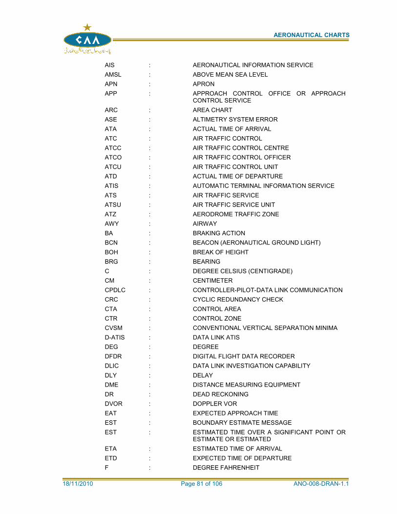
AERONAUTICAL CHARTS
18/11/2010 Page 81 of 106 ANO-008-DRAN-1.1
AIS : AERONAUTICAL INFORMATION SERVICE
AMSL : ABOVE MEAN SEA LEVEL
APN : APRON
APP : APPROACH CONTROL OFFICE OR APPROACH CONTROL SERVICE
ARC : AREA CHART
ASE : ALTIMETRY SYSTEM ERROR
ATA : ACTUAL TIME OF ARRIVAL
ATC : AIR TRAFFIC CONTROL
ATCC : AIR TRAFFIC CONTROL CENTRE
ATCO : AIR TRAFFIC CONTROL OFFICER
ATCU : AIR TRAFFIC CONTROL UNIT
ATD : ACTUAL TIME OF DEPARTURE
ATIS : AUTOMATIC TERMINAL INFORMATION SERVICE
ATS : AIR TRAFFIC SERVICE
ATSU : AIR TRAFFIC SERVICE UNIT
ATZ : AERODROME TRAFFIC ZONE
AWY : AIRWAY
BA : BRAKING ACTION
BCN : BEACON (AERONAUTICAL GROUND LIGHT)
BOH : BREAK OF HEIGHT
BRG : BEARING
C : DEGREE CELSIUS (CENTIGRADE)
CM : CENTIMETER
CPDLC : CONTROLLER-PILOT-DATA LINK COMMUNICATION
CRC : CYCLIC REDUNDANCY CHECK
CTA : CONTROL AREA
CTR : CONTROL ZONE
CVSM : CONVENTIONAL VERTICAL SEPARATION MINIMA
D-ATIS : DATA LINK ATIS
DEG : DEGREE
DFDR : DIGITAL FLIGHT DATA RECORDER
DLIC : DATA LINK INVESTIGATION CAPABILITY
DLY : DELAY
DME : DISTANCE MEASURING EQUIPMENT
DR : DEAD RECKONING
DVOR : DOPPLER VOR
EAT : EXPECTED APPROACH TIME
EST : BOUNDARY ESTIMATE MESSAGE
EST : ESTIMATED TIME OVER A SIGNIFICANT POINT OR ESTIMATE OR ESTIMATED
ETA : ESTIMATED TIME OF ARRIVAL
ETD : EXPECTED TIME OF DEPARTURE
F : DEGREE FAHRENHEIT
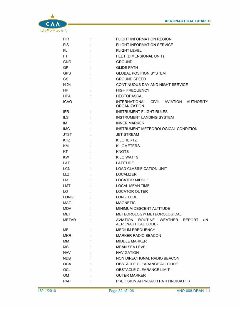
AERONAUTICAL CHARTS
18/11/2010 Page 82 of 106 ANO-008-DRAN-1.1
FIR : FLIGHT INFORMATION REGION
FIS : FLIGHT INFORMATION SERVICE
FL : FLIGHT LEVEL
FT : FEET (DIMENSIONAL UNIT)
GND : GROUND
GP : GLIDE PATH
GPS : GLOBAL POSITION SYSTEM
GS : GROUND SPEED
H 24 : CONTINUOUS DAY AND NIGHT SERVICE
HF : HIGH FREQUENCY
HPA : HECTOPASCAL
ICAO : INTERNATIONAL CIVIL AVIATION AUTHORITY ORGANIZATION
IFR : INSTRUMENT FLIGHT RULES
ILS : INSTRUMENT LANDING SYSTEM
IM : INNER MARKER
IMC : INSTRUMENT METEOROLOGICAL CONDITION
JTST : JET STREAM
KHZ : KILOHERTZ
KM : KILOMETERS
KT : KNOTS
KW : KILO WATTS
LAT : LATITUDE
LCN : LOAD CLASSIFICATION UNIT
LLZ : LOCALIZER
LM : LOCATOR MIDDLE
LMT : LOCAL MEAN TIME
LO : LOCATOR OUTER
LONG : LONGITUDE
MAG : MAGNETIC
MDA : MINIMUM DESCENT ALTITUDE
MET : METEOROLOGY/ METEOROLOGICAL
METAR : AVIATION ROUTINE WEATHER REPORT (IN AERONAUTICAL CODE)
MF : MEDIUM FREQUENCY
MKR : MARKER RADIO BEACON
MM : MIDDLE MARKER
MSL : MEAN SEA LEVEL
NAV : NAVIGATION
NDB : NON DIRECTIONAL RADIO BEACON
OCA : OBSTACLE CLEARANCE ALTITUDE
OCL : OBSTACLE CLEARANCE LIMIT
OM : OUTER MARKER
PAPI : PRECISION APPROACH PATH INDICATOR
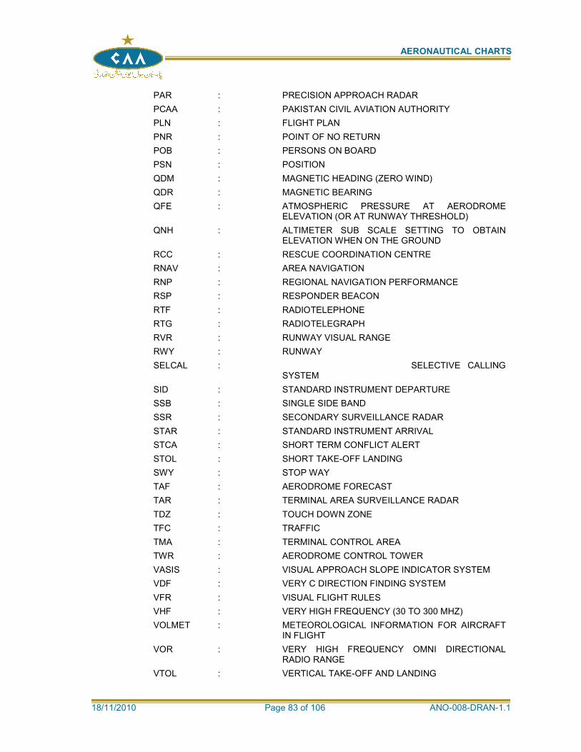
AERONAUTICAL CHARTS
18/11/2010 Page 83 of 106 ANO-008-DRAN-1.1
PAR : PRECISION APPROACH RADAR
PCAA : PAKISTAN CIVIL AVIATION AUTHORITY
PLN : FLIGHT PLAN
PNR : POINT OF NO RETURN
POB : PERSONS ON BOARD
PSN : POSITION
QDM : MAGNETIC HEADING (ZERO WIND)
QDR : MAGNETIC BEARING
QFE : ATMOSPHERIC PRESSURE AT AERODROME ELEVATION (OR AT RUNWAY THRESHOLD)
QNH : ALTIMETER SUB SCALE SETTING TO OBTAIN ELEVATION WHEN ON THE GROUND
RCC : RESCUE COORDINATION CENTRE
RNAV : AREA NAVIGATION
RNP : REGIONAL NAVIGATION PERFORMANCE
RSP : RESPONDER BEACON
RTF : RADIOTELEPHONE
RTG : RADIOTELEGRAPH
RVR : RUNWAY VISUAL RANGE
RWY : RUNWAY
SELCAL : SELECTIVE CALLING SYSTEM
SID : STANDARD INSTRUMENT DEPARTURE
SSB : SINGLE SIDE BAND
SSR : SECONDARY SURVEILLANCE RADAR
STAR : STANDARD INSTRUMENT ARRIVAL
STCA : SHORT TERM CONFLICT ALERT
STOL : SHORT TAKE-OFF LANDING
SWY : STOP WAY
TAF : AERODROME FORECAST
TAR : TERMINAL AREA SURVEILLANCE RADAR
TDZ : TOUCH DOWN ZONE
TFC : TRAFFIC
TMA : TERMINAL CONTROL AREA
TWR : AERODROME CONTROL TOWER
VASIS : VISUAL APPROACH SLOPE INDICATOR SYSTEM
VDF : VERY C DIRECTION FINDING SYSTEM
VFR : VISUAL FLIGHT RULES
VHF : VERY HIGH FREQUENCY (30 TO 300 MHZ)
VOLMET : METEOROLOGICAL INFORMATION FOR AIRCRAFT IN FLIGHT
VOR : VERY HIGH FREQUENCY OMNI DIRECTIONAL RADIO RANGE
VTOL : VERTICAL TAKE-OFF AND LANDING
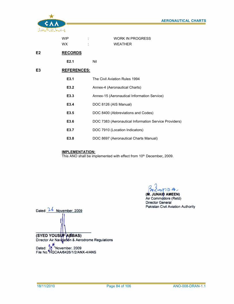
AERONAUTICAL CHARTS
18/11/2010 Page 84 of 106 ANO-008-DRAN-1.1
WIP : WORK IN PROGRESS
WX : WEATHER
E2 RECORDS
E2.1 Nil
E3 REFERENCES:
E3.1 The Civil Aviation Rules 1994
E3.2 Annex-4 (Aeronautical Charts)
E3.3 Annex-15 (Aeronautical Information Service)
E3.4 DOC 8126 (AIS Manual)
E3.5 DOC 8400 (Abbreviations and Codes)
E3.6 DOC 7383 (Aeronautical Information Service Providers)
E3.7 DOC 7910 (Location Indicators)
E3.8 DOC 8697 (Aeronautical Charts Manual)
IMPLEMENTATION: This ANO shall be implemented with effect from 10th December, 2009.
(M. JUNAID AMEEN)
Air Commodore (Retd) Director General Pakistan Civil Aviation Authority
Dated: November, 2009
(SYED YOUSUF ABBAS) Director Air Navigation & Aerodrome Regulations Dated: November, 2009 File No. HQCAA/6426/1/2/ANX-4/ANS

AERONAUTICAL CHARTS
18/11/2010 Page 85 of 106 ANO-008-DRAN-1.1
APPENDIX 1
MARGINAL NOTE LAYOUT
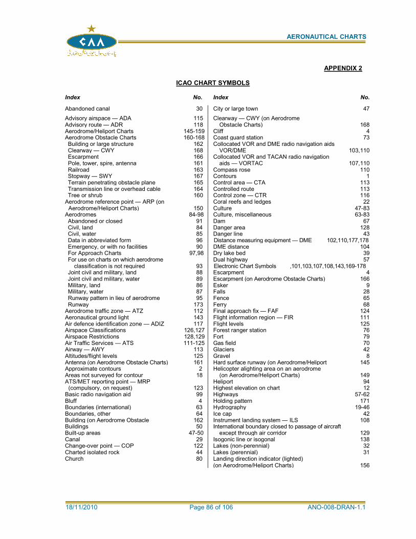
AERONAUTICAL CHARTS
18/11/2010 Page 86 of 106 ANO-008-DRAN-1.1
APPENDIX 2
ICAO CHART SYMBOLS Index No. Index No.
Abandoned canal 30 City or large town 47
Advisory airspace — ADA 115 Clearway — CWY (on Aerodrome Advisory route — ADR 118 Obstacle Charts) 168 Aerodrome/Heliport Charts 145-159 Cliff 4 Aerodrome Obstacle Charts 160-168 Coast guard station 73 Building or large structure 162 Collocated VOR and DME radio navigation aids Clearway — CWY 168 VOR/DME 103,110 Escarpment 166 Collocated VOR and TACAN radio navigation Pole, tower, spire, antenna 161 aids — VORTAC 107,110 Railroad 163 Compass rose 110 Stopway — SWY 167 Contours 1 Terrain penetrating obstacle plane 165 Control area — CTA 113 Transmission line or overhead cable 164 Controlled route 113 Tree or shrub 160 Control zone — CTR 116
Aerodrome reference point — ARP (on Coral reefs and ledges 22 Aerodrome/Heliport Charts) 150 Culture 47-83
Aerodromes 84-98 Culture, miscellaneous 63-83 Abandoned or closed 91 Dam 67 Civil, land 84 Danger area 128 Civil, water 85 Danger line 43 Data in abbreviated form 96 Distance measuring equipment — DME 102,110,177,178 Emergency, or with no facilities 90 DME distance 104 For Approach Charts 97,98 Dry lake bed 39 For use on charts on which aerodrome Dual highway 57
classification is not required 93 Electronic Chart Symbols ,101,103,107,108,143,169-178 Joint civil and military, land 88 Escarpment 4 Joint civil and military, water 89 Escarpment (on Aerodrome Obstacle Charts) 166 Military, land 86 Esker 9 Military, water 87 Falls 28 Runway pattern in lieu of aerodrome 95 Fence 65 Runway 173 Ferry 68
Aerodrome traffic zone — ATZ 112 Final approach fix — FAF 124 Aeronautical ground light 143 Flight information region — FIR 111 Air defence identification zone — ADIZ 117 Flight levels 125 Airspace Classifications 126,127 Forest ranger station 76 Airspace Restrictions 128,129 Fort 79 Air Traffic Services — ATS 111-125 Gas field 70 Airway — AWY 113 Glaciers 42 Altitudes/flight levels 125 Gravel 8 Antenna (on Aerodrome Obstacle Charts) 161 Hard surface runway (on Aerodrome/Heliport 145 Approximate contours 2 Helicopter alighting area on an aerodrome Areas not surveyed for contour 18 (on Aerodrome/Heliport Charts) 149 ATS/MET reporting point — MRP Heliport 94
(compulsory, on request) 123 Highest elevation on chart 12 Basic radio navigation aid 99 Highways 57-62 Bluff 4 Holding pattern 171 Boundaries (international) 63 Hydrography 19-46 Boundaries, other 64 Ice cap 42 Building (on Aerodrome Obstacle 162 Instrument landing system — ILS 108 Buildings 50 International boundary closed to passage of aircraft Built-up areas 47-50 except through air corridor 129 Canal 29 Isogonic line or isogonal 138 Change-over point — COP 122 Lakes (non-perennial) 32 Charted isolated rock 44 Lakes (perennial) 31 Church 80 Landing direction indicator (lighted)
(on Aerodrome/Heliport Charts)
156
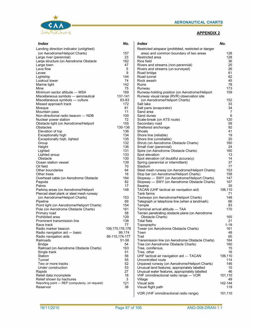
AERONAUTICAL CHARTS
18/11/2010 Page 87 of 106 ANO-008-DRAN-1.1
Index No. Index No.
Landing direction indicator (unlighted) Restricted airspace (prohibited, restricted or danger
(on Aerodrome/Heliport Charts) 157 area) and common boundary of two areas 128 Large river (perennial) 23 Restricted area 128 Large structure (on Aerodrome Obstacle 162 Rice field 36 Large town 47 Rivers and streams (non-perennial) 25 Lava flow 5 Rivers and streams (un-surveyed) 26 Levee 9 Road bridge 61 Lightship 144 Road tunnel 62 Lookout tower 74 Rock awash 45 Marine light 142 Ruins 78 Mine 75 Runway 173 Minimum sector altitude — MSA 169 Runway-holding position (on Aerodrome/Heliport 159 Miscellaneous symbols — aeronautical 137-141 Runway visual range (RVR) observation site Miscellaneous symbols — culture 63-83 (on Aerodrome/Heliport Charts) 152 Missed approach track 172 Salt lake 33 Mosque 81 Salt pans (evaporator) 34 Mountain pass 11 Sand area 7 Non-directional radio beacon — NDB 100 Sand dunes 6 Nuclear power station 72 Scale-break (on ATS route) 120 Obstacle light (on Aerodrome/Heliport 155 Secondary road 59 Obstacles 130-136 Sheltered anchorage 92
Elevation of top 136 Shoals 41 Exceptionally high 134 Shore line (reliable) 19 Exceptionally high, lighted 135 Shore line (unreliable) 20 Group 132 Shrub (on Aerodrome Obstacle Charts) 160 Height 136 Small river (perennial) 24 Lighted 131 Spire (on Aerodrome Obstacle Charts) 160 Lighted group 133 Spot elevation 13 Obstacle 130 Spot elevation (of doubtful accuracy) 14
Ocean station vessel 139 Spring (perennial or intermittent) 37 Oil field 70 Stadium 77 Other boundaries 64 Steel mesh runway (on Aerodrome/Heliport Charts) 153 Other trees 16 Stop bar (on Aerodrome/Heliport Charts) 158 Overhead cable (on Aerodrome Obstacle 164 Stopway — SWY (on Aerodrome/Heliport Charts) 147 Pagoda 82 Stopway — SWY (on Aerodrome Obstacle Charts) 167 Palms 17 Swamp 35 Parking areas (on Aerodrome/Heliport 148 TACAN (UHF tactical air navigation aid) 106,110 Pierced steel plank or steel mesh runway Tank farms 71
(on Aerodrome/Heliport Charts) 153 Taxiways (on Aerodrome/Heliport Charts) 148 Pipeline 69 Telegraph or telephone line (when a landmark) 66 Point light (on Aerodrome/Heliport Charts) 154 Temple 83 Pole (on Aerodrome Obstacle Charts) 161 Terminal arrival altitude — TAA 170 Primary road 58 Terrain penetrating obstacle plane (on Aerodrome Prohibited area 129 Obstacle Charts) 165 Prominent transmission line 138 Tidal flats 21 Race track 77 Topography 1-18 Radio marker beacon 109,175,176,178 Tower (on Aerodrome Obstacle Charts) 161 Radio navigation aid — basic 99,174 Town 48 Radio navigation aids 99-110,174-177 Trail 60 Railroads 51-56 Transmission line (on Aerodrome Obstacle Charts) 164
Bridge 54 Tree (on Aerodrome Obstacle Charts) 160 Railroad (on Aerodrome Obstacle Charts) 163 Tree, coniferous 15 Single track 51 Tree, other 16 Station 56 UHF tactical air navigation aid — TACAN 106,110 Tunnel 55 Uncontrolled route 114 Two or more tracks 52 Unpaved runway (on Aerodrome/Heliport Charts) 146 Under construction 53 Unusual land features, appropriately labelled 10
Rapids 27 Unusual water features, appropriately labelled 46 Relief data incomplete 18 VHF omnidirectional radio range — VOR 101,110 Relief shown by hachures 3 Village 49 Reporting point — REP (compulsory, on request) 121 Visual aids 142-144 Reservoir 38 Visual flight path 119
VOR (VHF omnidirectional radio range) 101,110
APPENDIX 2
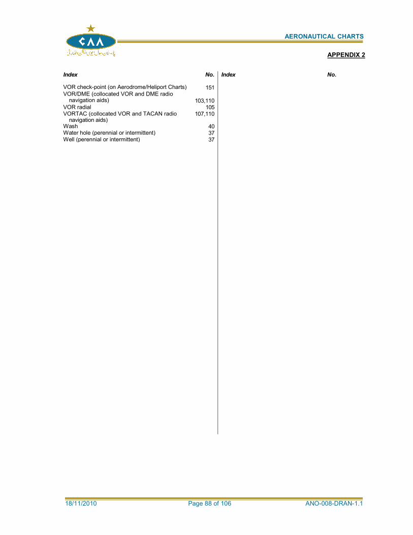
AERONAUTICAL CHARTS
18/11/2010 Page 88 of 106 ANO-008-DRAN-1.1
Index No. Index No.
VOR check-point (on Aerodrome/Heliport Charts) 151 VOR/DME (collocated VOR and DME radio
navigation aids)
103,110
VOR radial 105 VORTAC (collocated VOR and TACAN radio
navigation aids) 107,110
Wash 40 Water hole (perennial or intermittent) 37 Well (perennial or intermittent) 37
APPENDIX 2
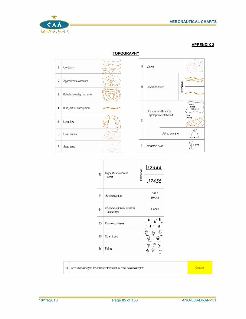
AERONAUTICAL CHARTS
18/11/2010 Page 89 of 106 ANO-008-DRAN-1.1
APPENDIX 2
TOPOGRAPHY
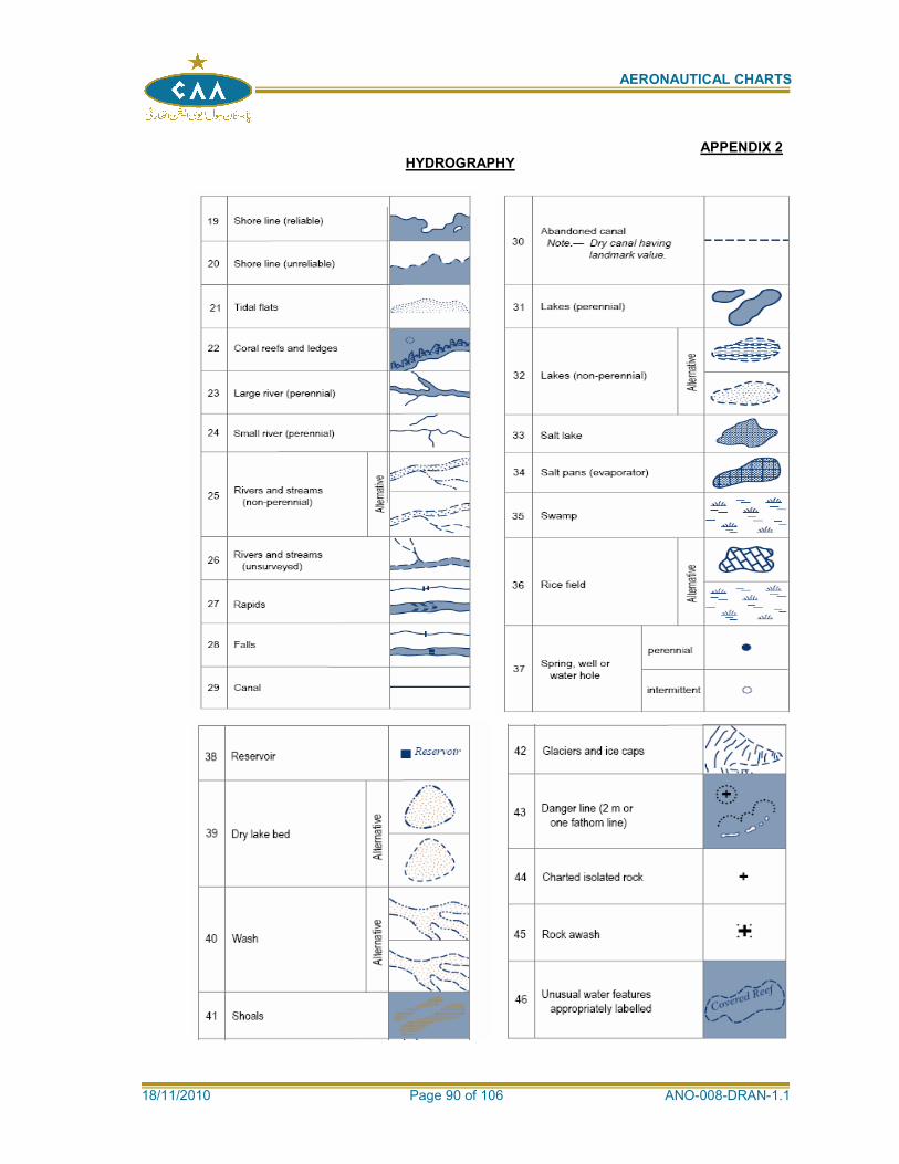
AERONAUTICAL CHARTS
18/11/2010 Page 90 of 106 ANO-008-DRAN-1.1
APPENDIX 2 HYDROGRAPHY
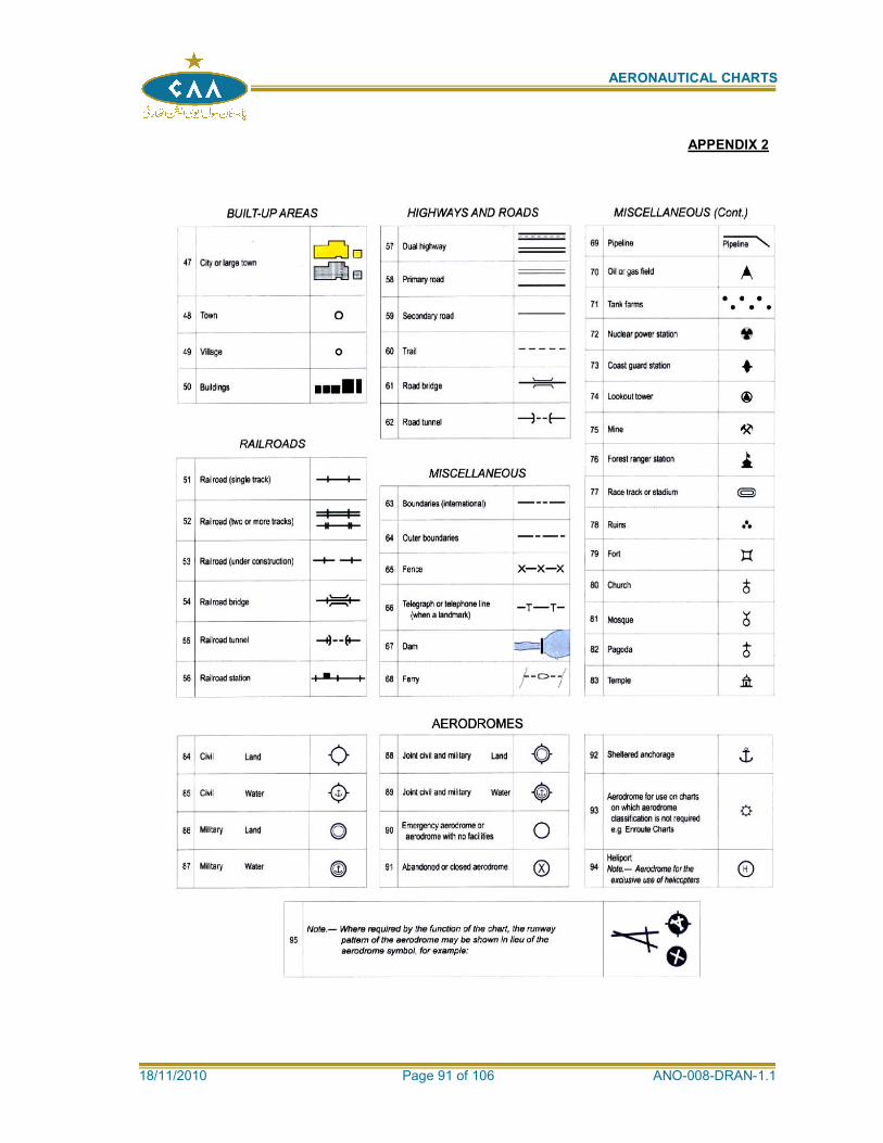
AERONAUTICAL CHARTS
18/11/2010 Page 91 of 106 ANO-008-DRAN-1.1
APPENDIX 2
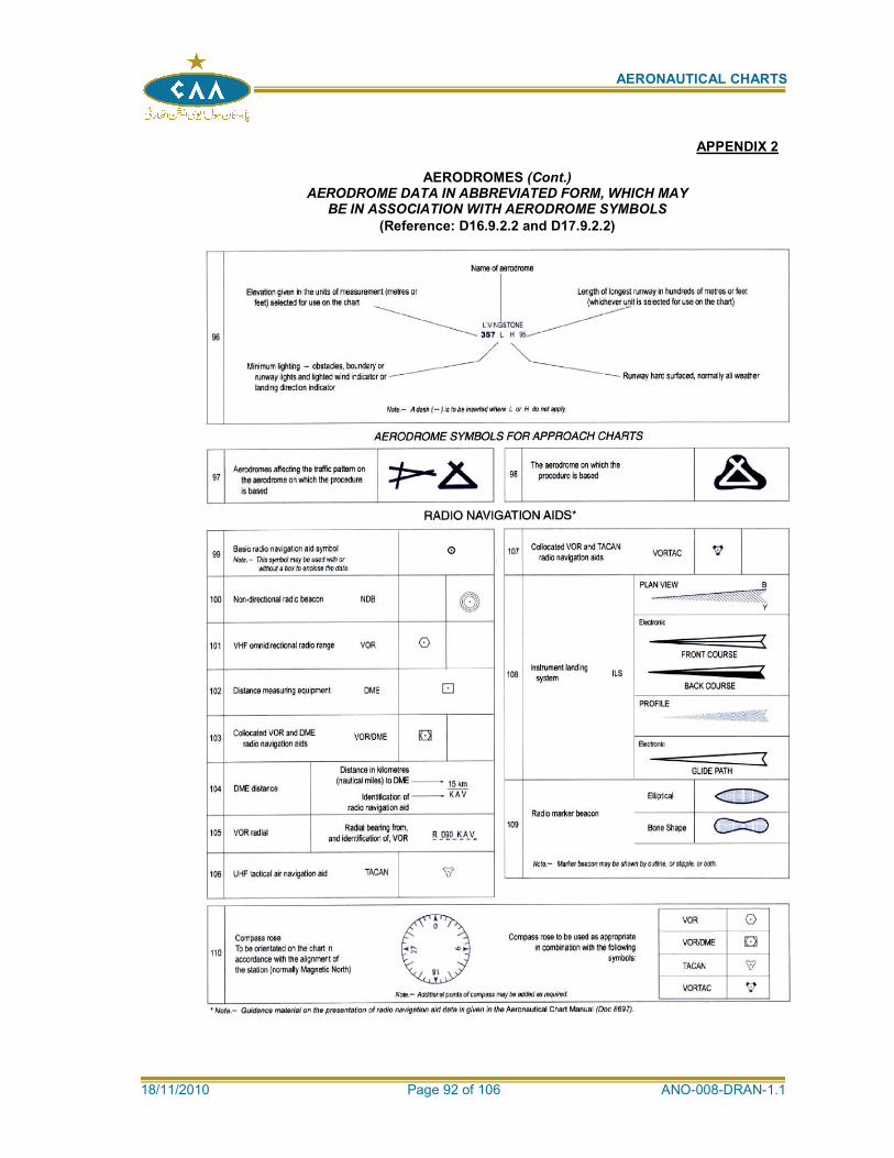
AERONAUTICAL CHARTS
18/11/2010 Page 92 of 106 ANO-008-DRAN-1.1
APPENDIX 2
AERODROMES (Cont.) AERODROME DATA IN ABBREVIATED FORM, WHICH MAY
BE IN ASSOCIATION WITH AERODROME SYMBOLS
(Reference: D16.9.2.2 and D17.9.2.2)
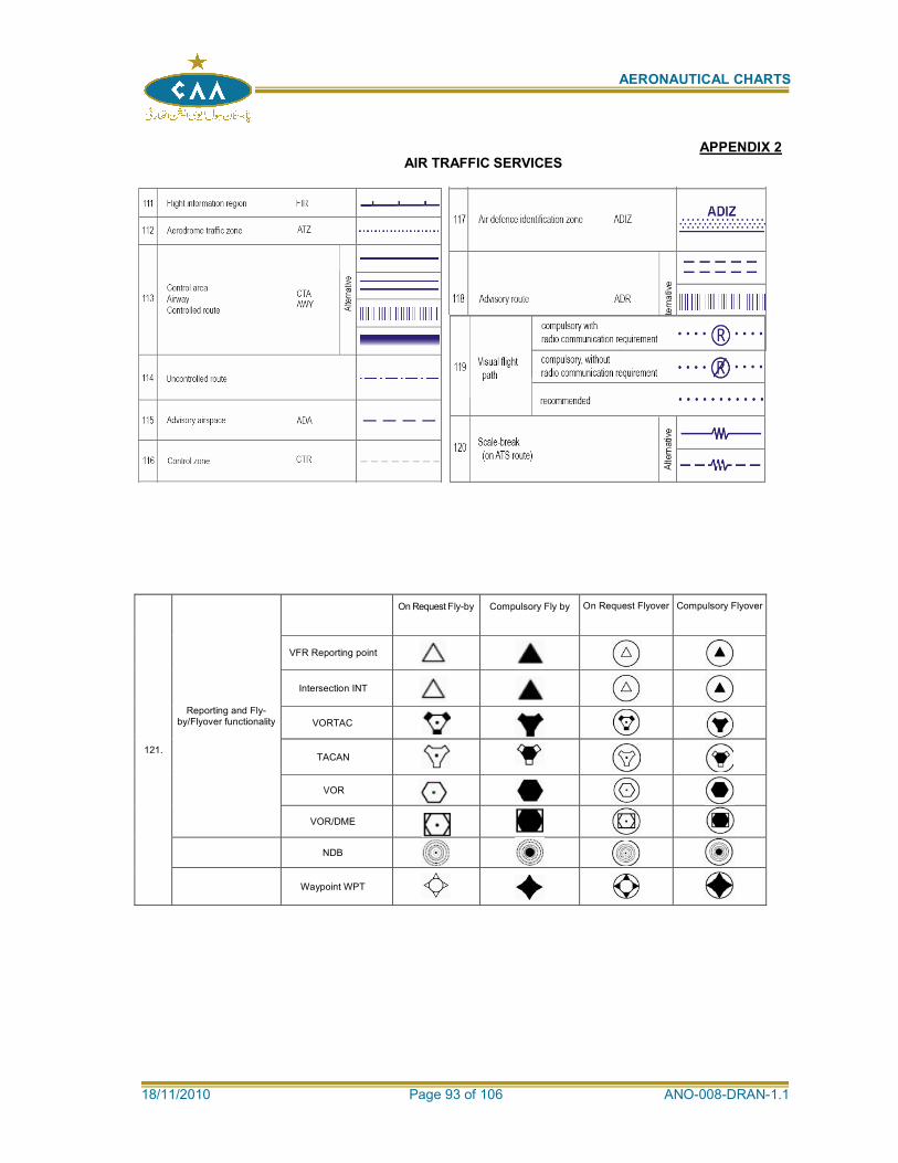
AERONAUTICAL CHARTS
18/11/2010 Page 93 of 106 ANO-008-DRAN-1.1
APPENDIX 2 AIR TRAFFIC SERVICES
121.
Reporting and Fly-by/Flyover functionality
On Request Fly-by Compulsory Fly by On Request Flyover Compulsory Flyover
VFR Reporting point
Intersection INT
VORTAC
TACAN
VOR
VOR/DME
NDB
Waypoint WPT
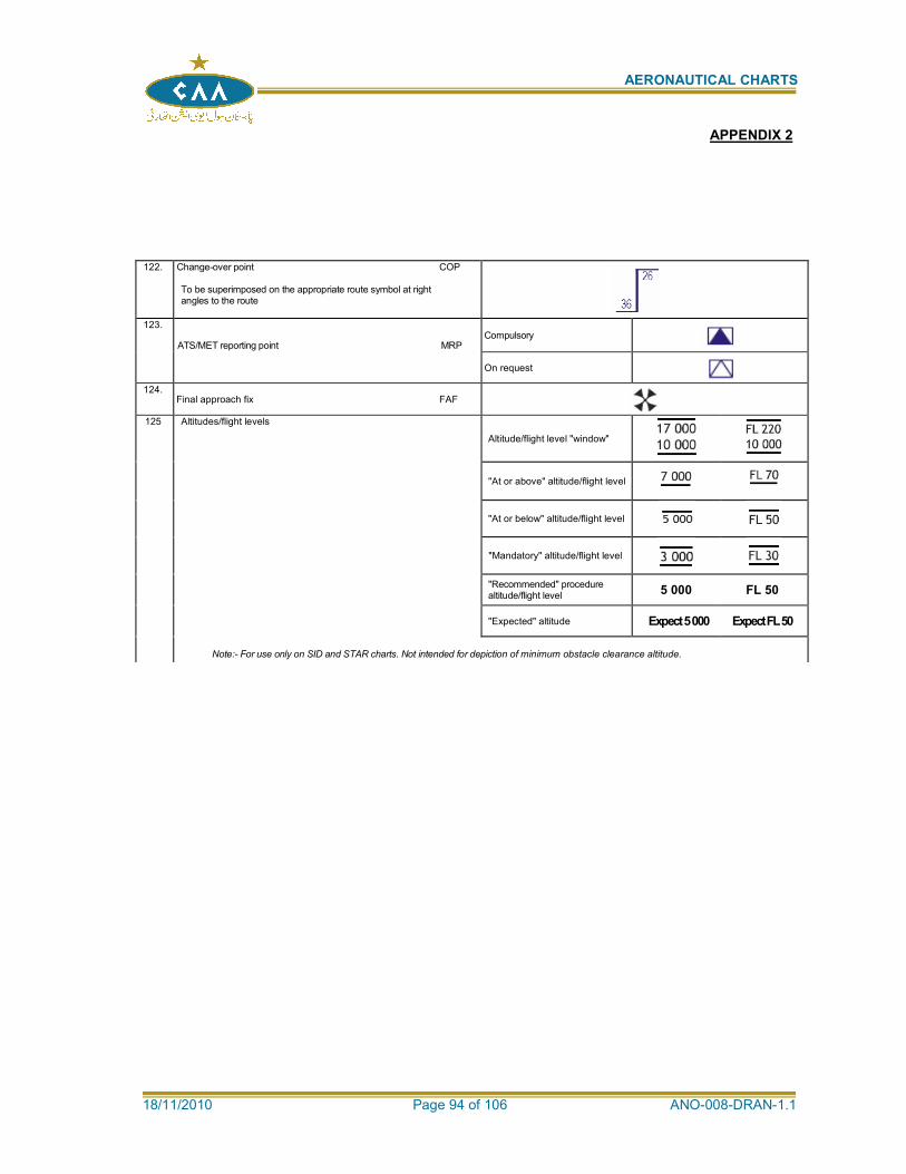
AERONAUTICAL CHARTS
18/11/2010 Page 94 of 106 ANO-008-DRAN-1.1
122. Change-over point COP To be superimposed on the appropriate route symbol at right angles to the route
123.
ATS/MET reporting point MRP
Compulsory
On request
124. Final approach fix FAF
125 Altitudes/flight levels
Altitude/flight level "window"
"At or above" altitude/flight level
"At or below" altitude/flight level
"Mandatory" altitude/flight level
"Recommended" procedure altitude/flight level
5 000 FL 50
"Expected" altitude Expect 5 000 Expect FL 50
Note:- For use only on SID and STAR charts. Not intended for depiction of minimum obstacle clearance altitude.
APPENDIX 2
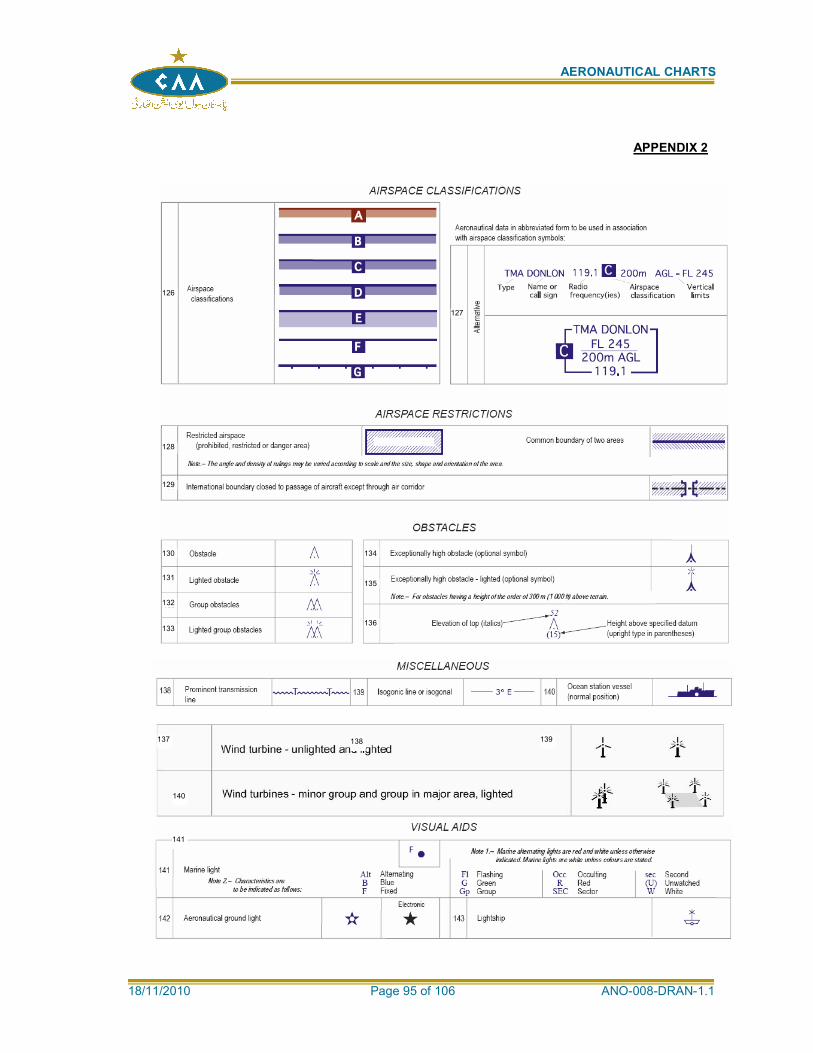
AERONAUTICAL CHARTS
18/11/2010 Page 95 of 106 ANO-008-DRAN-1.1
APPENDIX 2
126
127
128
129
130
131
132
133
134
135
136 137
136
138 139
140
141

AERONAUTICAL CHARTS
18/11/2010 Page 96 of 106 ANO-008-DRAN-1.1
142
143 144
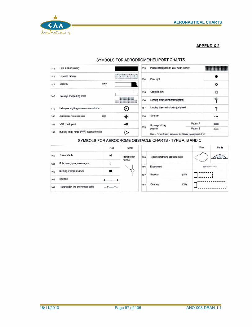
AERONAUTICAL CHARTS
18/11/2010 Page 97 of 106 ANO-008-DRAN-1.1
APPENDIX 2
145
146
147
148
149
150
151
152
155
153
154
156
157
158
159
160
161
162
164
163
165
166
167
168
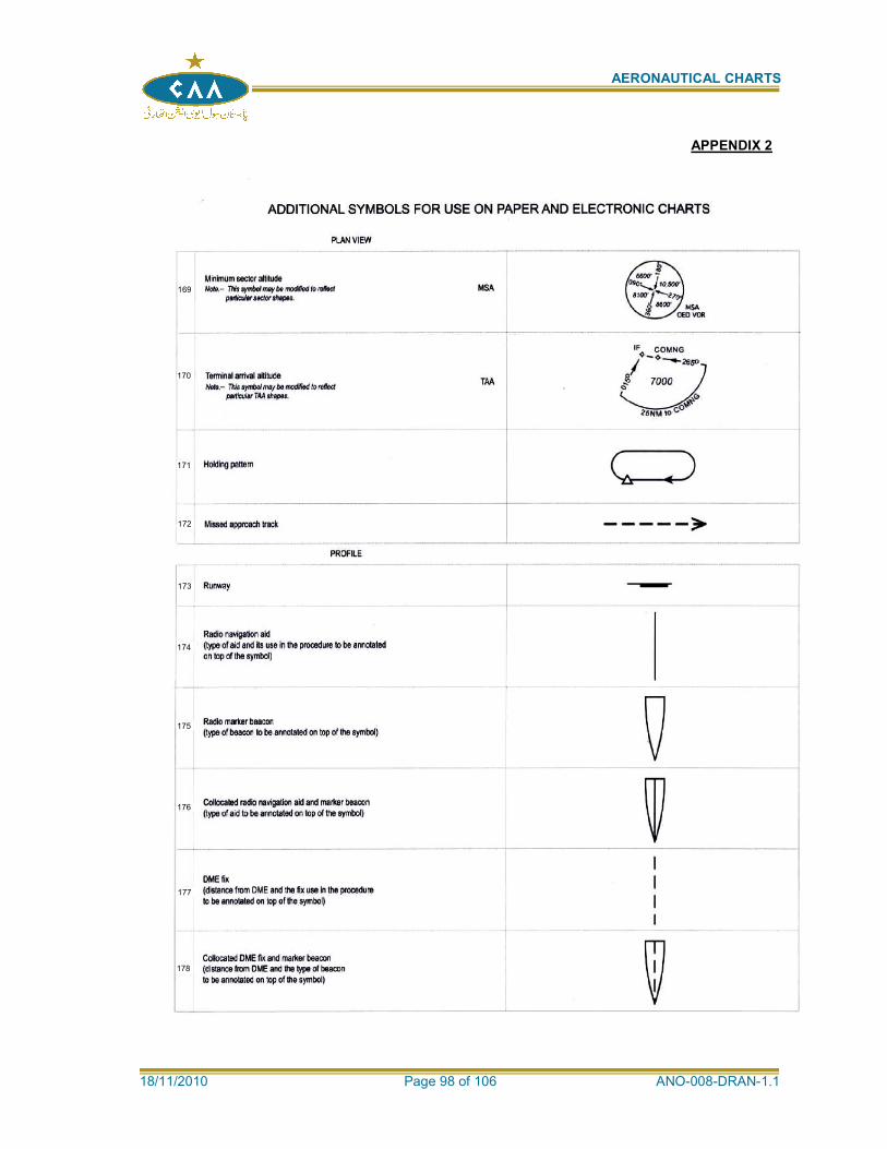
AERONAUTICAL CHARTS
18/11/2010 Page 98 of 106 ANO-008-DRAN-1.1
APPENDIX 2
169
170
171
172
173
174
175
176
177
178
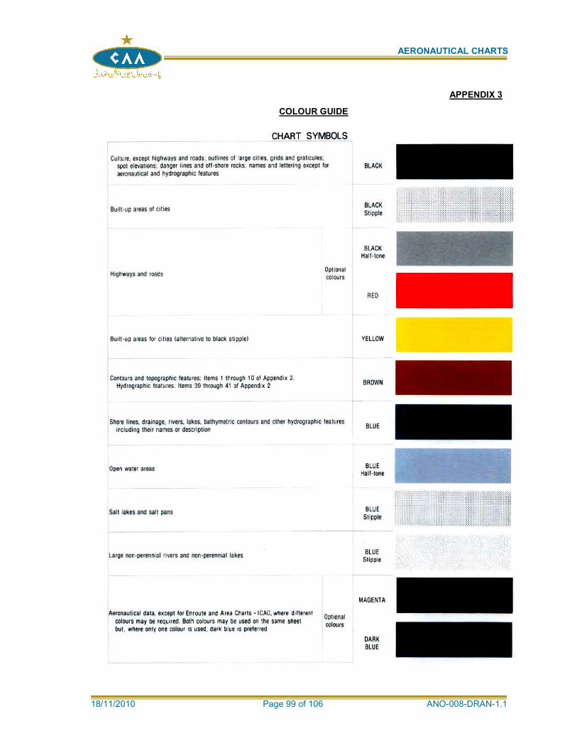
AERONAUTICAL CHARTS
18/11/2010 Page 99 of 106 ANO-008-DRAN-1.1
APPENDIX 3
COLOUR GUIDE
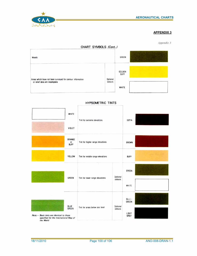
AERONAUTICAL CHARTS
18/11/2010 Page 100 of 106 ANO-008-DRAN-1.1
APPENDIX 3
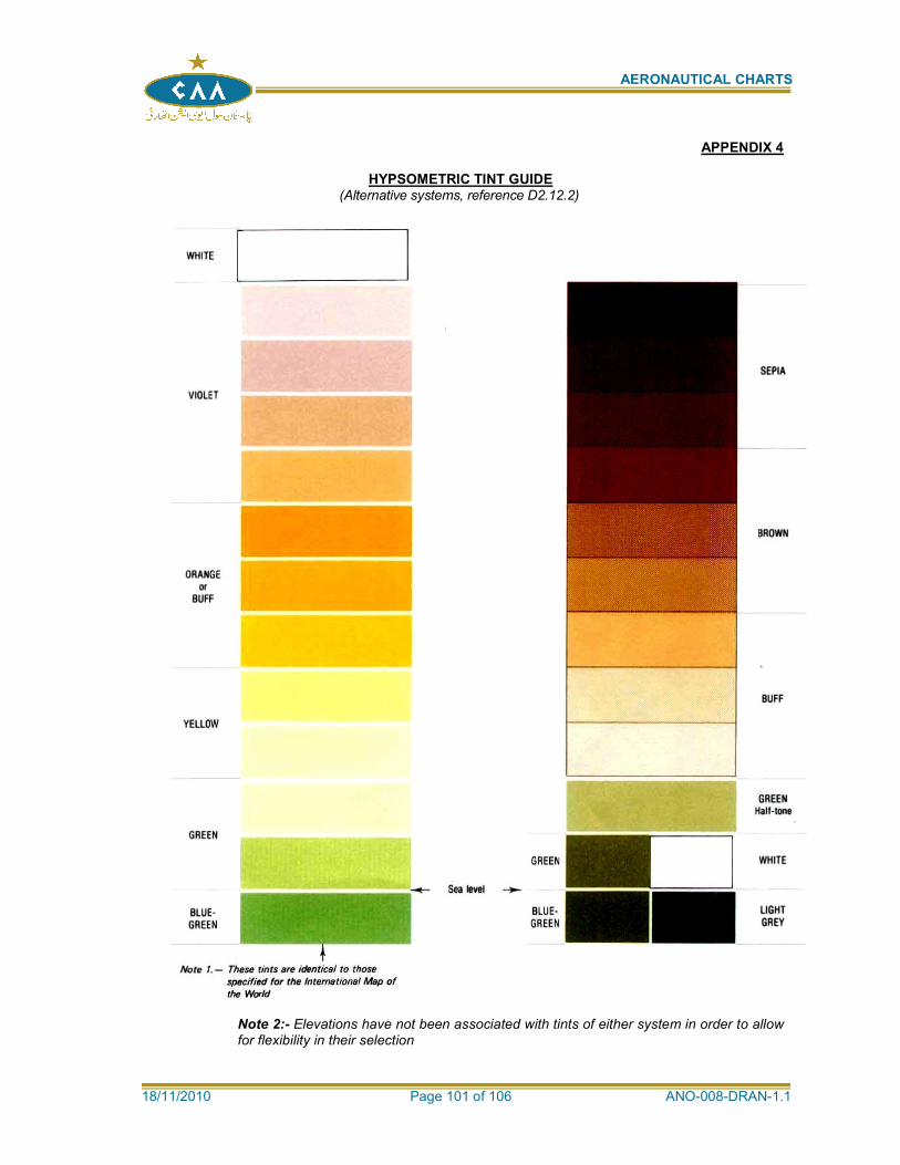
AERONAUTICAL CHARTS
18/11/2010 Page 101 of 106 ANO-008-DRAN-1.1
APPENDIX 4
HYPSOMETRIC TINT GUIDE (Alternative systems, reference D2.12.2)
Note 2:- Elevations have not been associated with tints of either system in order to allow for flexibility in their selection
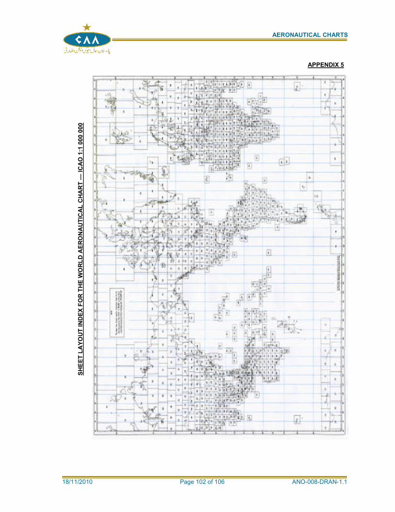
AERONAUTICAL CHARTS
18/11/2010 Page 102 of 106 ANO-008-DRAN-1.1
APPENDIX 5
SH
EE
T L
AY
OU
T I
ND
EX
FO
R T
HE
WO
RL
D A
ER
ON
AU
TIC
AL
CH
AR
T —
IC
AO
1:1
00
0 0
00
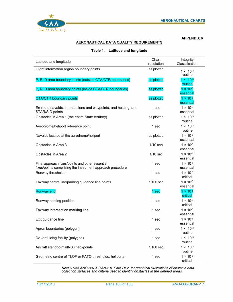
AERONAUTICAL CHARTS
18/11/2010 Page 103 of 106 ANO-008-DRAN-1.1
APPENDIX 6 AERONAUTICAL DATA QUALITY REQUIREMENTS
Table 1. Latitude and longitude
Latitude and longitude Chart
resolution Integrity
Classification
Flight information region boundary points as plotted 1 × 10⁻³
routine
P, R, D area boundary points (outside CTA/CTR boundaries) as plotted 1 × 10⁻³
routine
P, R, D area boundary points (inside CTA/CTR boundaries) as plotted 1 × 10⁻⁵
essential
CTA/CTR boundary points as plotted 1 × 10⁻⁵
essential
En-route navaids, intersections and waypoints, and holding, and STAR/SID points
1 sec 1 × 10⁻⁵
essential
Obstacles in Area 1 (the entire State territory) as plotted 1 × 10⁻³
routine
Aerodrome/heliport reference point 1 sec 1 × 10⁻³
routine
Navaids located at the aerodrome/heliport as plotted 1 × 10⁻⁵
essential
Obstacles in Area 3 1/10 sec 1 × 10⁻⁵
essential
Obstacles in Area 2 1/10 sec 1 × 10⁻⁵
essential
Final approach fixes/points and other essential fixes/points comprising the instrument approach procedure
1 sec 1 × 10⁻⁵
essential
Runway thresholds 1 sec 1 × 10⁻⁸
critical
Taxiway centre line/parking guidance line points 1/100 sec 1 × 10⁻⁵
essential
Runway end 1 sec 1 × 10⁻⁸
critical
Runway holding position 1 sec 1 × 10⁻⁸
critical
Taxiway intersection marking line 1 sec 1 × 10⁻⁵
essential
Exit guidance line 1 sec 1 × 10⁻⁵
essential
Apron boundaries (polygon) 1 sec 1 × 10⁻³
routine
De-/anti-icing facility (polygon) 1 sec 1 × 10⁻³
routine
Aircraft standpoints/INS checkpoints 1/100 sec 1 × 10⁻³
routine
Geometric centre of TLOF or FATO thresholds, heliports 1 sec 1 × 10⁻⁸
critical Note:- See ANO-007-DRAN-2.0, Para D12, for graphical illustrations of obstacle data collection surfaces and criteria used to identify obstacles in the defined areas.
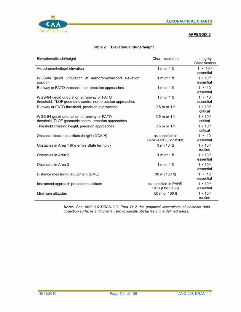
AERONAUTICAL CHARTS
18/11/2010 Page 104 of 106 ANO-008-DRAN-1.1
Table 2. Elevation/altitude/height
Elevation/altitude/height Chart resolution Integrity Classification
Aerodrome/heliport elevation 1 m or 1 ft 1 × 10⁻⁵
essential
WGS-84 geoid undulation at aerodrome/heliport elevation position
1 m or 1 ft 1 × 10⁻⁵
essential
Runway or FATO threshold, non-precision approaches 1 m or 1 ft 1 × 10 essential
WGS-84 geoid undulation at runway or FATO threshold, TLOF geometric centre, non-precision approaches
1 m or 1 ft 1 × 10 essential
Runway or FATO threshold, precision approaches 0.5 m or 1 ft 1 × 10⁻⁸
critical
WGS-84 geoid undulation at runway or FATO threshold, TLOF geometric centre, precision approaches
0.5 m or 1 ft 1 × 10⁻⁸
critical
Threshold crossing height, precision approaches 0.5 m or 1 ft 1 × 10⁻⁸
critical
Obstacle clearance altitude/height (OCA/H) as specified in PANS-OPS (Doc 8168)
1 × 10 essential
Obstacles in Area 1 (the entire State territory) 3 m (10 ft) 1 × 10⁻³
routine
Obstacles in Area 2 1 m or 1 ft 1 × 10⁻⁵
essential
Obstacles in Area 3 1 m or 1 ft 1 × 10⁻⁵
essential
Distance measuring equipment (DME) 30 m (100 ft) 1 × 10 essential
Instrument approach procedures altitude as specified in PANS-OPS (Doc 8168)
1 × 10⁻⁵
essential
Minimum altitudes 50 m or 100 ft 1 × 10⁻³
routine
Note:- See ANO-007-DRAN-2.0, Para D12, for graphical illustrations of obstacle data
collection surfaces and criteria used to identify obstacles in the defined areas.
APPENDIX 6
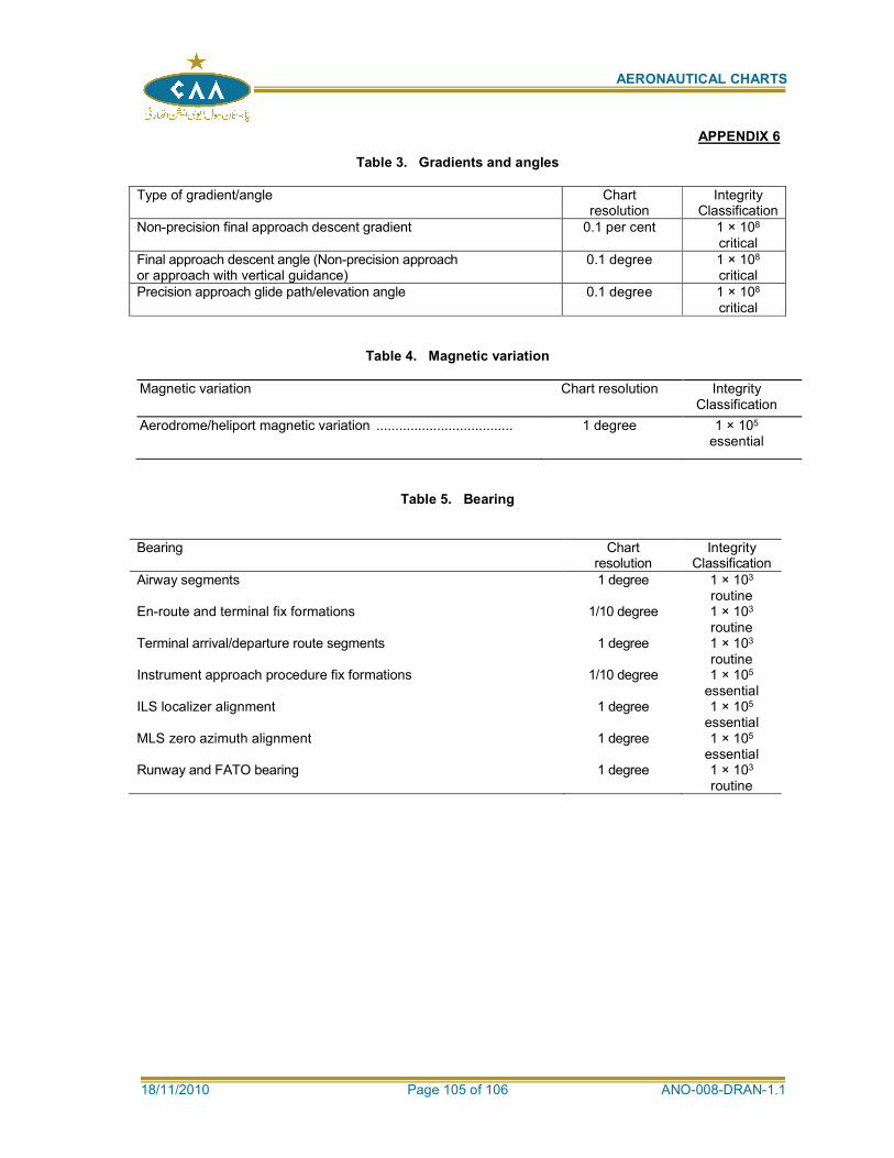
AERONAUTICAL CHARTS
18/11/2010 Page 105 of 106 ANO-008-DRAN-1.1
Table 3. Gradients and angles
Type of gradient/angle Chart resolution
Integrity Classification
Non-precision final approach descent gradient 0.1 per cent 1 × 10⁸
critical
Final approach descent angle (Non-precision approach or approach with vertical guidance)
0.1 degree 1 × 10⁸
critical
Precision approach glide path/elevation angle 0.1 degree 1 × 10⁸
critical
Table 4. Magnetic variation
Magnetic variation Chart resolution Integrity Classification
Aerodrome/heliport magnetic variation .................................... 1 degree 1 × 10⁵
essential
Table 5. Bearing
Bearing Chart resolution
Integrity Classification
Airway segments 1 degree 1 × 10³
routine En-route and terminal fix formations 1/10 degree 1 × 10³
routine Terminal arrival/departure route segments 1 degree 1 × 10³
routine Instrument approach procedure fix formations 1/10 degree 1 × 10⁵
essential ILS localizer alignment 1 degree 1 × 10⁵
essential MLS zero azimuth alignment 1 degree 1 × 10⁵
essential Runway and FATO bearing 1 degree 1 × 10³
routine
APPENDIX 6
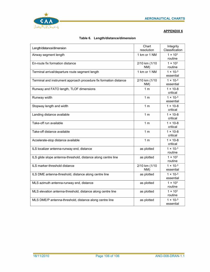
AERONAUTICAL CHARTS
18/11/2010 Page 106 of 106 ANO-008-DRAN-1.1
Table 6. Length/distance/dimension
Length/distance/dimension Chart
resolution Integrity
Classification
Airway segment length 1 km or 1 NM 1 × 10³
routine
En-route fix formation distance 2/10 km (1/10 NM)
1 × 10³
routine
Terminal arrival/departure route segment length 1 km or 1 NM 1 × 10⁻⁵
essential
Terminal and instrument approach procedure fix formation distance 2/10 km (1/10 NM)
1 × 10⁻⁵
essential
Runway and FATO length, TLOF dimensions 1 m 1 × 10⁻⁸ critical
Runway width 1 m 1 × 10⁻⁵
essential
Stopway length and width 1 m 1 × 10⁻⁸ critical
Landing distance available 1 m 1 × 10⁻⁸ critical
Take-off run available 1 m 1 × 10⁻⁸ critical
Take-off distance available 1 m 1 × 10⁻⁸ critical
Accelerate-stop distance available 1 m 1 × 10⁻⁸ critical
ILS localizer antenna-runway end, distance as plotted 1 × 10⁻³
routine
ILS glide slope antenna-threshold, distance along centre line as plotted 1 × 10³
routine
ILS marker-threshold distance 2/10 km (1/10 NM)
1 × 10⁻⁵
essential
ILS DME antenna-threshold, distance along centre line as plotted 1 × 10⁻⁵
essential
MLS azimuth antenna-runway end, distance as plotted 1 × 10³
routine
MLS elevation antenna-threshold, distance along centre line as plotted 1 × 10³
routine
MLS DME/P antenna-threshold, distance along centre line as plotted 1 × 10⁻⁵
essential
APPENDIX 6
Related Documents


