1 ANNUAL REPORT 2005 Meeting date: June 1, 2005 Seid Koric * & Brian G. Thomas •Engineering Applications Analyst, NCSA & Ph. D. Candidate Department of Mechanical & Industrial Engineering University of Illinois at Urbana-Champaign Solidification Stress Modeling using ABAQUS University of Illinois at Urbana-Champaign • Metals Processing Simulation Lab • S. Koric 2 Objectives To predict the evolution of temperature, shape, stress and strain distribution in the solidifying shell in continuous casting mold by a nonlinear multipurpose commercial finite element package with an accurate approach. Validate the model with available analytical solution and benchmarks with in-house code CON2D specializing in accurate modeling of 2D continuous casting. To enable new model to be applied to the continuous casting problems by incorporating even more complete and realistic phenomena. To perform a unique realistic 3D thermal stress analysis of solidification of the shell of a thin slab caster that can accurately predict the 3D mechanical state in some critical regions important to crack formation. Apply FE results to predict the effects of casting speed on total strain evolution, to predict maximum casting speed to avoid bulging, to predict damage strains and transverse and longitudinal cracks, to find ideal taper and more.

Welcome message from author
This document is posted to help you gain knowledge. Please leave a comment to let me know what you think about it! Share it to your friends and learn new things together.
Transcript

1
ANNUAL REPORT 2005Meeting date: June 1, 2005
Seid Koric* & Brian G. Thomas•Engineering Applications Analyst, NCSA &
Ph. D. Candidate
Department of Mechanical & Industrial EngineeringUniversity of Illinois at Urbana-Champaign
Solidification Stress Modeling using ABAQUS
University of Illinois at Urbana-Champaign • Metals Processing Simulation Lab • S. Koric 2
Objectives
To predict the evolution of temperature, shape, stress and strain distribution in the solidifying shell in continuous casting mold by a nonlinear multipurpose commercial finite element package with an accurate approach.
Validate the model with available analytical solution and benchmarks with in-house code CON2D specializing in accurate modeling of 2D continuous casting.
To enable new model to be applied to the continuous casting problems by incorporating even more complete and realistic phenomena.
To perform a unique realistic 3D thermal stress analysis of solidification of the shell of a thin slab caster that can accurately predict the 3D mechanical state in some critical regions important to crack formation.
Apply FE results to predict the effects of casting speed on total strain evolution, to predict maximum casting speed to avoid bulging, to predict damage strains and transverse and longitudinal cracks, to find ideal taper and more.
2
University of Illinois at Urbana-Champaign • Metals Processing Simulation Lab • S. Koric 3
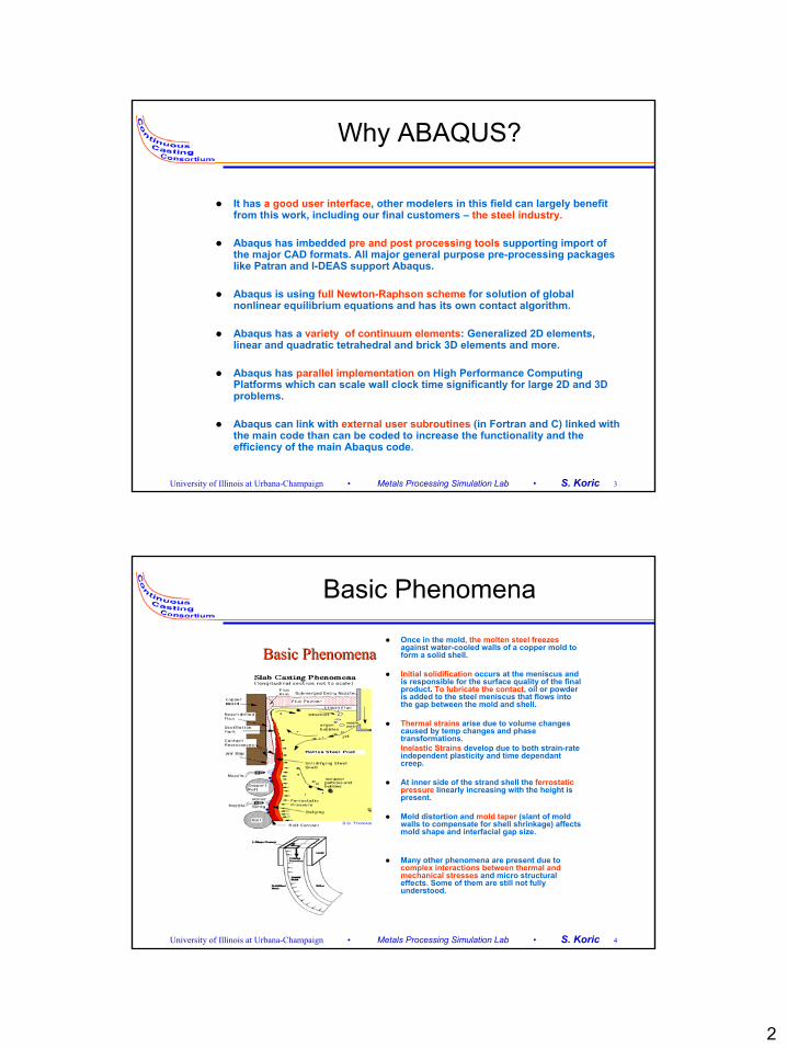
Why ABAQUS?
It has a good user interface, other modelers in this field can largely benefit from this work, including our final customers – the steel industry.
Abaqus has imbedded pre and post processing tools supporting import of the major CAD formats. All major general purpose pre-processing packages like Patran and I-DEAS support Abaqus.
Abaqus is using full Newton-Raphson scheme for solution of global nonlinear equilibrium equations and has its own contact algorithm.
Abaqus has a variety of continuum elements: Generalized 2D elements, linear and quadratic tetrahedral and brick 3D elements and more.
Abaqus has parallel implementation on High Performance Computing Platforms which can scale wall clock time significantly for large 2D and 3D problems.
Abaqus can link with external user subroutines (in Fortran and C) linked with the main code than can be coded to increase the functionality and the efficiency of the main Abaqus code.
University of Illinois at Urbana-Champaign • Metals Processing Simulation Lab • S. Koric 4
Basic Phenomena
Basic PhenomenaBasic PhenomenaOnce in the mold, the molten steel freezes against water-cooled walls of a copper mold to form a solid shell.
Initial solidification occurs at the meniscus and is responsible for the surface quality of the final product. To lubricate the contact, oil or powder is added to the steel meniscus that flows into the gap between the mold and shell.
Thermal strains arise due to volume changes caused by temp changes and phase transformations.Inelastic Strains develop due to both strain-rate independent plasticity and time dependant creep.
At inner side of the strand shell the ferrostaticpressure linearly increasing with the height is present.
Mold distortion and mold taper (slant of mold walls to compensate for shell shrinkage) affects mold shape and interfacial gap size.
Many other phenomena are present due tocomplex interactions between thermal and mechanical stresses and micro structural effects. Some of them are still not fully understood.

3
University of Illinois at Urbana-Champaign • Metals Processing Simulation Lab • S. Koric 5
Governing Equations
Heat Equation:
Equilibrium Equation (small strain assumption):
Rate Representation of Total Strain Decomposition:
Constitutive Law (Rate Form, No large rotations):
Inelastic (visco-plastic) Strain Rate (strain rate independent plasticity + creep):
Thermal Strain:
( ) ( ) ( )H T T T Tk T k TT t x x y y
ρ ∂ ∂ ∂ ∂ ∂ ∂ = + ∂ ∂ ∂ ∂ ∂ ∂
( ) 0ox b∇ ⋅ σ + =
ie th:( )= − −D & & &&σ ε ε ε 22 (k )3
= µ + − ⊗D I I I
thieel εεεε &&&& ++=
)C,%,T,(f ieie εσ=ε&
{ } ( ) ( )( ) [ ]Trefiirefth 000111TT)T(TT)T( −α−−α=ε
ie ie ie3 1 2: , trace( ) , :2 3 3
σ = = − σ ε =& & &S S S Iσ ε ε
University of Illinois at Urbana-Champaign • Metals Processing Simulation Lab • S. Koric 6
Computational Methods Used to Solve Governing Equations
Global Solution Methods (solving global FE equations)
-Full Newton-Raphson used by Abaqus
-Operator-Splitting used by CON2D
Local Integration Methods (on every material points integrating constitutive laws)
-Abaqus provided via CREEP subroutine, fully implicit followed by local NR
-Abaqus provided via CREEP subroutine, explicit
-Fully Implicit followed by local bounded NR
-Fully Implicit followed by Nemat-Nasser
-Radial Return Method for Rate Independent Plasticity, for liquid/mushy zone only

4
University of Illinois at Urbana-Champaign • Metals Processing Simulation Lab • S. Koric 7
Big Picture: Materially Non-Linear FEM Solution Strategy in ABAQUS with UMAT
IterationNR Global
[ ] [ ] { } { } { } { } 0i ; UU ; SS ; KK ttt0
ttt0
ttt0 ==== ∆+∆+∆+
1ii +=
[ ]{ } { } { }{ } { } { }-1i
tt-1i
tti
tt-1i
tt-1i
tt-1i
U U U
S - P U K
∆+=
=∆∆+∆+
∆+∆+∆+
Tolerance
{ } { } { }ttti
tti U - U U ∆+∆+ =∆
t t tYes
∆+=
IterationNR newStart No,
{ } { } { } ∑∫ ∫t+∆t T t+∆t T t+∆t
V A
P = N b dV + N Φ dA
ttat Vector Load External Global ∆+
{ } { } { } t t t
Equilibrium Configuration at t
U , S , P{ } Ttttt
tt
0} 0 0 1 1 {1 T )(T database HT from T Nodal Read
∆+∆+∆+
∆+
=αε ttth
{ } [ ]{ }ttiU B
Increment StrainElement ∆+∆+ ∆=∆ tt
iε
{ } { } { }tie
ttt , , Points Gauss allat
called UMAT
εεσ ∆+∆
[ ] { }{ }∂
∂
t+∆t
t+∆t
Stress Update AlgorithamImplicit Integration of IVP
Calculation of CTO :
σJ =
∆ε
{ } { } [ ]J , , ttie
tt ∆+∆+ εσ
{ } { }
[ ][ ]
E
∫
∫
t+∆t T t+∆tel , i
Vel
t+∆t Tel, i Vel
lement Internal Force and Element Tangent Matrix
S = B σ dV
K = B J B dV[ ] [ ] { } { }∑∑ ∆+∆+∆+∆+ == tt
iel,tt
eltt
i el,tt
i S S , K K
University of Illinois at Urbana-Champaign • Metals Processing Simulation Lab • S. Koric 8
Big Picture 2: CON2D Solution ProcedureOperator Splitting Technique (No global iterations, no CTO !)
Given:Calculate Trial Stress: LOCAL STEP: Implicit Integration of constitutive law followed by 2 level local bounded NR.Local Step Output:
Radial Return Factor: Stress Estimate Expansion:
Inelastic Strain Rate Estimate:
GLOBAL STEP: Finite Element Solution of equilibrium equation.Using constitutive law with initial strain.Inelastic strain rate based on estimate from Step1Solve linear global system for only once for every time increment:
Update Values :
Update Stress:
{ } { } { }t t tie, ,∆ε σ ε
t t t tie
ˆˆ ,+∆ +∆σ ε
{ } [ ] { } { } { } { }( ) { } { } { }t t t t t tt t t t t* t t * * *ie th hydD , S
+∆ +∆ +∆+∆ +∆σ = ε − ε + ε + ∆ε = σ − σ
t t
*t t
ˆ +∆
+∆
σα =
σ{ } { } { }t t t tt t * *
hydˆ S+∆ +∆+∆σ = α + σ
( ) { } { }t tt tt t t t t t t t
ie ie ie iet t
S3ˆ ˆˆˆˆf , , ˆ2
+∆+∆
+∆ +∆ +∆ +∆+∆
ε = σ ε ε = εσ
:Flow Ru le& &&
{ } { } { }
{ } { } { }el el el
el el
t tt t t tT T Tie th
V V V
t t t t tT T Tel
V V S
ˆ[B ][D][B]dV d [B ][D] tdV [B ][D] dV
[B ][D] dV [N ] b dV [N ] dAφ
+∆+∆ +∆
+∆ +∆
Σ ∆ = Σ ε ∆ +Σ ∆ε −
−Σ ε + Σ +Σ φ
∫ ∫ ∫
∫ ∫ ∫
&
{ }t t
ieˆ +∆ε&
{ }t td +∆∆
{ } { } { } { } { } { } { }t tt t t t t t t t t t tie ie
ˆd d d , [B] d , t+∆+∆ +∆ +∆ +∆ +∆
= + ∆ ∆ε = ∆ ∆ε = ε ∆&
{ } { } { } { } { }( )t t t t t t t t tie th[D]+∆ +∆ +∆ +∆σ = σ + ∆ε − ∆ε − ∆ε

5
University of Illinois at Urbana-Champaign • Metals Processing Simulation Lab • S. Koric 9
Constitutive Models for Solid Steel (T<=Tsol)
Plastic Strain (%)
Stre
ss(M
Pa)
0 2 4 6 80
5
10
15
20
25 Strain Rate = 1x10⁻⁴ 1/sec.
Symbols: Experiments [YM WON, Met. Trans. B, 2000]Lines: CON2D (Koslowski III)
1100 oC
1200 oC
1300 oC
Plastic Strain (%)St
ress
(MPa
)0 2 4 6 80
1
2
3
CON2D, 1425 oCCON2D, 1525 oCExperiment, 1425 oCExperiment, 1525 oC
Strain Rate = 1.4x10⁻⁴
Kozlowski III Law for Austenite Power Law for δ-ferrite
Modified Power Law for Delta-Ferrite (Parkman 2000)
Kozlowski Model for Austenite (Kozlowski 1991)
University of Illinois at Urbana-Champaign • Metals Processing Simulation Lab • S. Koric 10
Constitutive Models for Solid Steel (T<=Tsol)
Kozlowski Model for Austenite (Kozlowski 1991)
Modified Power Law for Delta-Ferrite (Parkman 2000)
( ) ( ) ( ) ( )( ) ( )( ) ( )( )( ) ( )( )
( )( ) ( )( )( ) ( )( )( ) ( )
( )
32 1 4
1
31
32
33
24 4 5
1/ sec. % exp 4.465 10
130.5 5.128 10
0.6289 1.114 10
8.132 1.54 10
(% ) 4.655 10 7.14 10 % 1.2 10 %
oo f T K
f T Ko o o
o o
o o
o o
f C MPa f T K K T K
f T K T K
f T K T K
f T K T K
f C C C
ε σ ε ε −
−
−
−
= − − ×
= − ×
= − + ×
= − ×
= × + × + ×
&
( ) ( ) ( )( )( ) ( )
( )( )
2
5.52
5.56 104
5
4
1/ sec. 0.1 (% ) 300 (1 1000 )
% 1.3678 10 %
9.4156 10 0.3495
1 1.617 10 0.06166
no m
o
o
MPa f C T K
f C C
m T K
n T K
ε σ ε
−
−
− ×
−
−
= +
= ×
= − × +
= × −
&

6
University of Illinois at Urbana-Champaign • Metals Processing Simulation Lab • S. Koric 11
1D Solidification Stress Problem for Program Validation
Analytical Solution exists (Weiner & Boley1963). Elastic in solid, Perfectly Plastic in liquid/mushy. No viscoplastic law for solid yet in this model.
Provides an extremely useful validation test for integration methods, since stress update algorithm in liquid/mushy zone is a major challenge !
Yield stress linearly drops with temp. from 20Mpa @ 1000C to 0.03Mpa @ SolidusTemp 1494.35C
A strip of 2D elements used as a 1D FE Domain for validation
Generalized plane strain both in y and z direction to give 3D stress/strain state
Tested both of our methods to emulate Elastic-Perfectly Plastic material behavior plus both Abaqus native CREEP integration methods.
University of Illinois at Urbana-Champaign • Metals Processing Simulation Lab • S. Koric 12
Constants Used in Abaqus Numerical Solution of WB Analytical Test Problem
Conductivity [W/mK] 33.Specific Heat [J/kg/K] 661.Elastic Modulus in Solid [Gpa] 40.Elastic Modulus in Liq. [Gpa] 14.Thermal Linear Exp. [1/k] 2.E-5Density [kg/m3] 7500.Poisson’s Ratio 0.3Liquidus Temp [O C] 1494.48Solidus Temp [O C] 1494.38Initial Temp [O C] 1495.Latent Heat [J/kgK] 272000.Number of Elements 300.Uniform Element Length [mm] 0.1
Artificial and non-physical thermal BC from VB (slab surface quenched to 1000C),replaced by a convective BC with h=220000 [W/m2K]
Simple calculation to get h, from surface energy balance at initial instant of time:
and for finite values)( ∞−=∂∂
− TThxTk 495
0001.049533 h=

7
University of Illinois at Urbana-Champaign • Metals Processing Simulation Lab • S. Koric 13
Analytical, CON2D, and Abaqus Temperature and Stress Results (Weiner-Boley)
0 5 10 15 20 25 301000
1100
1200
1300
1400
1500
Distance to the chilled surface [mm]
Tem
pera
ture
[C]
Analytical 5 secAbaqus 5 secCON2D 5 secAnalytical 21 secAbaqus 21 secCON2D 21 sec
0 5 10 15 20 25 30-25
-20
-15
-10
-5
0
5
10
15
Distance to the chilled surface [mm]
Str
ess
[MP
a]
Analytical 5 secAbaqus 5 secCON2D 5 secAnalytical 21 secAbaqus 21 secCON2D 21 sec
All different Stress Update Integration methods in Abaqus yield the same result, and are represented by a single Abaqus curve in bellow stress graph.
University of Illinois at Urbana-Champaign • Metals Processing Simulation Lab • S. Koric 14
Solidifying Slice (0.27 %C) with Realistic Heat Flux and Temperature Dependant Material Properties
1000 1200 1400 16000.7
0.8
0.9
1
1.1
1.2
1.3
1.4x 10⁶
Temperature [C]
Ent
halp
y [J
/kg]
Hf
1000 1200 1400 160030
32
34
36
38
40
Temperature [C]
Con
duct
ivity
[W/m
K]
259.3 W/mK in Liquid
0 5 10 15 20 251
2
3
4
5
6
7
Time Bellow Meniscus [sec]
Surfa
ce H
eat F
lux
[MW
/m2 ]
1000 1100 1200 1300 1400 1500 16001.2
1.4
1.6
1.8
2
2.2
2.4x 10⁻⁵
Temperature [C]
Coe
ffici
ent o
f The
rmal
Exp
ansi
on [1
/K]

8
University of Illinois at Urbana-Champaign • Metals Processing Simulation Lab • S. Koric 15
Abaqus and CON2D Temperature and Stress Results for Realistic Solidifying Slice in CC Mold
0 5 10 15 20 25 30900
1000
1100
1200
1300
1400
1500
1600
Distance to the chilled surface [mm]
Tem
pera
ture
[C]
Abaqus 5 secCON2D 5 secAbaqus 21 secCON2D 21 sec
0 5 10 15 20 25 30-12
-10
-8
-6
-4
-2
0
2
4
6
Distance to the chilled surface [mm]
Stre
ss [M
Pa]
Abaqus 5 secCON2D 5 secAbaqus 21 secCON2D 21 sec
University of Illinois at Urbana-Champaign • Metals Processing Simulation Lab • S. Koric 16
CPU Benchmarking Results
CODE Global Method for Solving BVP
Local Integration Method
Treatment of Liq./Mushy zone
CPU time (Minutes)
Abaqus Full NR Implicit followed by local Bounded NR
Liquid Function 55
Abaqus Full NR Implicit followed by Nemat-Nasser
Liquid Function 53
Abaqus Full NR Implicit followed by local Bounded NR
Radial Return 5.6
Abaqus Full NR Implicit followed by loc. full NR (CREEP)
Radial Return or Liquid Function
Failed
Abaqus Full NR Explicit (CREEP) Liquid Function 185 CON2D Operator Splitting
(Initial Strain) Implicit followed by local Bounded NR
Liquid Function 6
CON2D Operator Splitting (Initial Strain)
Implicit followed by Nemat-Nasser
Liquid Function 5.9

9
University of Illinois at Urbana-Champaign • Metals Processing Simulation Lab • S. Koric 17
Conclusions
The temperature and stress results are matching very well between two codes. A small discrepancy between the stress results in thecoldest zone is under investigation.
It took Abaqus in average 2-3 iterations with its global full NR methods to achieve convergence, while CON2D is using explicit operator splitting technique to solve global equilibrium equations without any iterations per increment which is CPU cost effective, but might be prone to some minor errors and oscillations.
Local implicit integration followed by local bounded NR methodturned out to be the most efficient and robust method for integrating our highly nonlinear constitutive laws.
CPU time for Abaqus with our UMAT using local implicit rate independent plasticity algorithm (Radial Return) in liquid/mushy zone and fully implicit local integration method followed by local bounded NR in solid is totally comparable to CON2D, a clear sign that Abaqus with our UMAT is now ready to tackle large problems.
University of Illinois at Urbana-Champaign • Metals Processing Simulation Lab • S. Koric 18
Local Bounded NR versus Local Full NR, a key fast convergence

10
University of Illinois at Urbana-Champaign • Metals Processing Simulation Lab • S. Koric 19
Current & Future Work
Add more Phenomena (Physics) to the model in order to match real process condition: Internal BC with Ferrostatic Pressure, contact and friction between mold and shell, input mold distortion data.
Program a consistent tangent operator with respect to temperature in our UMAT and perform incrementally-coupled 2D analysis with Abaqus (L-Shape FE Domain).
Incorporate a realistic gap-size heat transfer coefficient that can produce a reasonable match with realistic heat flux from plant measurements.
Perform a realistic 3D thermal stress analysis with adequate mesh refinement of solidification of shell of a thin slab caster that can accurately predict the 3D mechanical state in some critical zones important to crack formation. This would be the first of its kind ever performed. With enough dofs (3D), parallel Abaqus features will be applied (each time increment solved in parallel on NCSA’s SMP machines). The UMAT presented here has been already coded for a 3D stress state.
Add constitutive model for steels with delta-ferrite.
University of Illinois at Urbana-Champaign • Metals Processing Simulation Lab • S. Koric 20
2D Application, Shell Behavior with strand corner
Courtesy of Chungsheng Li, CON2D
X(mm)
Y(m
m)
0 10 20 30 40 50 60 70
0
10
20
30
40
50
60
STRESS-Z(MPa)6421
-1-2-4-6
V=2.2 m/min V=4.4 m/min
Predict the temperature, stress, and strain evaluation across a 2D section of the strand
Predict the distorted shape of the strand
Good for billet and corner portions of the slab

11
University of Illinois at Urbana-Champaign • Metals Processing Simulation Lab • S. Koric 21
3D Application, Thin Slab Caster
Due to a funnel type mold, complex geometry in casting direction is causingan in-plane bending phenomena which was not modeled in 2D CON2Dmodels. Only a 3D model can give the accurate stress distribution.
University of Illinois at Urbana-Champaign • Metals Processing Simulation Lab • S. Koric 22
Crack defects in continuous cast slabs
Cracks form by combination of 1) tensile stress and2) metallurgical embrittlement
Surface Cracks (initiated in the mold)
Transverse cornerTransverse surfaceLongitudinal midfaceLongitudinal cornerStar
Off corner
Internal cracks (initiated at solidification front)
Midway StraighteningPinch roll
Radial streaks
Centerline Triple point Diagonal

12
University of Illinois at Urbana-Champaign • Metals Processing Simulation Lab • S. Koric 23
Acknowledgements
Prof. Brian G. ThomasChungsheng Li, PhD, Former UIUC studentHong Zhu, PhD, Former UIUC studentNational Center for Supercomputing Applications
Related Documents