Annexure JR Metal - Amirthamangalam 1 List of Annexures Annexure I Location Map (Topo Map & Administrative Set-up) Annexure II Survey Nos. – Combined Sketch Annexure III Site Photographs Annexure IV Plant Layout Annexure V Manufacturing Process Annexure VI Details of disposal of Solid & Liquid Wastes Annexure VII Drainage & Water Bodies Map Annexure VIII Water Balance Diagram Annexure IX Raw Material Consumption Annexure X Stack Characteristics Annexure XI Air Pollution Control Measures

Welcome message from author
This document is posted to help you gain knowledge. Please leave a comment to let me know what you think about it! Share it to your friends and learn new things together.
Transcript

Annexure JR Metal - Amirthamangalam 1
List of Annexures Annexure I Location Map (Topo Map & Administrative Set-up)
Annexure II Survey Nos. – Combined Sketch
Annexure III Site Photographs
Annexure IV Plant Layout
Annexure V Manufacturing Process
Annexure VI Details of disposal of Solid & Liquid Wastes
Annexure VII Drainage & Water Bodies Map
Annexure VIII Water Balance Diagram
Annexure IX Raw Material Consumption
Annexure X Stack Characteristics
Annexure XI Air Pollution Control Measures

Annexure JR Metal - Amirthamangalam 2
Annexure I
Location Map

Annexure JR Metal - Amirthamangalam 3

Annexure JR Metal - Amirthamangalam 4

Annexure JR Metal - Amirthamangalam 5
Annexure II Combined Sketch

Annexure JR Metal - Amirthamanagalam
6

Annexure JR Metal - Amirthamanagalam
7
Annexure III
Site Photograph

Annexure JR Metal - Amirthamanagalam
8
Site Photographs

Annexure JR Metal - Amirthamanagalam
9
Annexure IV
Plant Layout

Annexure JR Metal - Amirthamanagalam
10
Plant Layout

Annexure JR Metal - Amirthamanagalam
11
Annexure V
Manufacturing Process

Annexure JR Metal - Amirthamanagalam
12
Sponge Iron Plant
The plant consists of raw material preparation unit where iron ore and non-coking
coal are crushed and screened to obtain the required sizes. These required sizes are
conveyed to stock house for storing in the respective bins. No crushing is envisaged
for dolomite/limestone, as it is received mostly in 0-4 mm size form. This limestone
is conveyed to its respective bins. The sized materials stored in bins at stock house
are charged in rotary kiln with predetermined feed rates with the help of weigh
feeders, volumetric feeders, and conveyors.
The iron ore is preheated, and reduced to sponge iron in the rotary kiln at the
required and controlled temperatures and pressure. Carbon and volatile matter in
coal is utilised and converted into char. Dolomite is used for desulfurization, and in
the process becomes dolochar. Sponge iron, char and dolochar travel from kiln to
cooler and are cooled to about 80ºC by indirect cooling, using water as medium.
The material cooled and discharged from the cooler, is conveyed to product
separation system. A junction house is provided in between cooler & product
separation system, to take care of any eventualities occurring due to the breakdown
of the product separation system, which may happen due to breakdown of
equipment etc. The cooler discharged material is screened, and separated with the
help of magnetic separators. Sponge iron lumps and sponge iron fines are taken to
their respective bins. Dolochar, and char which are non magnetic are taken to a
single bin.
Annexure JR Metal - Amirthamanagalam
13
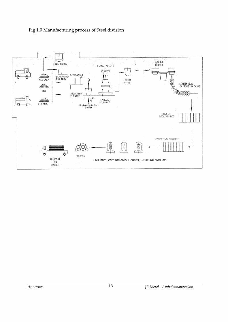
Fig 1.0 Manufacturing process of Steel division
TMT bars, Wire rod coils, Rounds, Structural products

Annexure JR Metal - Amirthamanagalam
14
Details of Steel Production Units Steel melting Shop
The Steel Melting Process can be subdivided into the following stages:-
Stage 1: Production of Liquid Metal from Induction Furnace.
Stage 2: Transfer of Liquid Steel to the Ladle Furnace
Stage 3: Continuous Casting.
Induction Furnace Scrap and Direct Reduction Iron (DRI) are the main raw materials for melting in the
Induction Furnace. The scrap and DRI will be brought into the steel plant premises
by Tipper / Dumpers / Trucks and unloaded either in the open scrap yard where it
will be intermittently stored or directly into the scrap bay, whereas, Sponge Iron is
produced within the Plant at Sponge Iron Plant. The usage of scrap and DRI in the
Steel Melt Shop is in the ratio of 56:44.
Raw Materials
Qty. in % fed in charge
Recovery
Qty. fed TPA for 6,00,000
Scrap + Cast iron Pieces
56% 96%
3,36,000
DRI 44% 82% 2,64,000
The capacity in the scrap bay of scrap and DRI will be in the same ratio. The scrap
bay will store the scrap and DRI in bins. In the scrap bay the trucks will be unloaded
by EOT cranes, and the tippers will tip the scrap / DRI into the bins directly.
From the bins in the Melting Bay EOT cranes will load the scrap in to a scrap bucket
which will be charged in to the Induction Furnace by EOT Crane. The first charge will
be of light scrap + cast iron pieces of about 3 T followed by DRI to be fed in 2-3
installments. The balance of heavy scrap is charged towards the end of the heat.

Annexure JR Metal - Amirthamanagalam
15
Fe metal C Si Mn P S
92.1% 0.25% 0.35% 0.5 % 0.03% 0.04%
The DRI will be mainly Coal based and will be in lumps with size range of 3 mm to 20 mm with a bulk density of about 2100 kg/ cum. The typical chemical composition of coal based DRI is:
Metallization Fe Total P S C Si
92% 94% 0.045% 0.02% 0.1% 1.8
Melting
The Induction Furnaces are Melting Units. The heat, and stirring in a coreless
Induction Furnace is caused by magnetic forces which result from the interaction of
the electrical current flowing in the induction coil, and in the molten bath itself melts
the metal and can increase the bath temp. to required temperature of 1600°C to
1650°C. Slag formed is taken out in the process.
The first charge of 3 t will consist of scrap and cast iron pieces only. DRI will be fed
in two or three installments. Frequent deslagging will be done to take the slag out. A
mechanical poker is provided to compact the scrap during feeding and to avoid the
formation of a bridge. The scrap mix used is shredded scrap, HMS, Cast Iron and
coal based DRI. Induction Furnace liquid steel output quality is dependent on the
quality of charge mix.
There will be 2 x 40 T Electric Induction Furnaces and 1 x 30 T Electric Induction
Furnace. The tapping temperature is maintained to approx. 1620°C.

Annexure JR Metal - Amirthamanagalam
16
The final chemistry of Liquid Metal from the induction furnace is:
C P S Temp.
0.30 max. 0.070 max 0.05 max. 1620 Deg.C
One heat in one Induction Furnace is estimated to take about 120 minutes on an
average. There will be two Induction Furnaces of 40T capacity + 1 No. of 30 T. The
Melting Bay has to therefore handle 48 heats every 24 hours.
Slag handling
The slag generated during melting will be to the extent of 10%. De-slagging will be
done by tilting the IF forward during the process while the power is reduced to a
minimum for 1-2 min. During the process of deslagging by forward tilting will be
done 5 - 6 times every heat. The slag will fall into in a slag box parked below the
Induction Furnace. The slag pot capacity will be 10 T to take care of the slag of each
heat. The slag pot will be lifted by the EOT crane and either be emptied in a dumper
or at the end of the bay. From there the slag will be taken to the slag dumping area.
Continuous Casting Machine
Liquid steel from ladle furnace is now placed in the Turret of the Continuous
Casting Machine. The Turret shall be moved and positioned over the tundish into
which the liquid steel will flow. From the tundish the liquid steel will flow into the
mould which shapes and forms the billet. The required starting ladle temperature
for the manufacture of billet for TMT rebars, wire rod, rounds, structural / grade at
the CCM is about 1650° C.
The hot billet goes through a water spray cooling chamber and comes to a
straightening cum withdrawal machine which is a set of individually driven rollers
with hydraulically pressed rollers.

Annexure JR Metal - Amirthamanagalam
17
The withdrawal machine also varies the speed of the billet to keep the level of the
mould constant as the steel flow into it varies as the metering nozzle erodes with
time. After the withdrawal machine is the oxy-fuel cutting machine which cuts the
billets into 6 m / 12 m length.
The billet by the time it reaches the cutting machine has no liquid core. The billets of
the 2 strands then come out onto a run out roller table and go into the run-in roller
table of the cooling bed. The transportation of the billets together from the run-in
roller table onto the cooling bed is done by an over head cross transfer for further
pushing of by a billet pusher on a skid Bank cooling bed.
A non-sequence casting cycle is as follows:
Placement of ladle on the Ladle turret : 2 min.
Moving the turret on position : 2.min.
Opening of the slide gate to start flow of : 1 min.
steel into the tundish
Opening the tundish metering nozzle : 1 min.
Start and end of casting including
slow start /slow finish : 25 min.
Total : 31 min.
Machine preparation : 20 min. After every sequence the CCM will have to be prepared again. The final output from
the CCM is 200 mm sq. billets in 6 m/ 12 m length.
Rolling Mill
The DRI – IF – CCM – RM route is considered for the integrated plant under
consideration, which is suitably supported by the Captive Power Plant. The main
technological facilities in different processing steps for production of rolled products

Annexure JR Metal - Amirthamanagalam
18
in DRI-SMS-RM route are as follows.
S.No Processing step Technological facility
1. Iron making Direct Reduction Plant
2. Steel making Induction Furnace
3. Casting Billet Caster
4. Rolling of Billets/ Blooms Rolling Mill
The Billets from Steel Melting Shop after Quality inspection are charged into
reheating furnace and at discharge end uniformly heated billets at a temperature of
about 1050OC – 1250OC (depending upon grade of Steel being rolled) are discharged
by an Ejector.
The heated billets are fed to different rolling mills to produce required size of
finished products.
The rolled product after last stand is transferred to Turnover Cooling Bed, and cut to
specified length and after Quality inspection and requisite Color Coding, bundling
etc. is shifted to despatch section.

Annexure JR Metal - Amirthamanagalam
19
WASTE HEAT RECOVERY – POWER GENERATION The process of sponge iron making by the DRI route produces a large quantity of
flue furnace gas. About 3500 N.Cu.m of flue gas with a calorific value of 900
K.Cal/N.Cu.m will be generated per ton of hot metal produced. It is estimated to
generate about 15 tons per hour of steam, which inturn generates about 8000 KW
power per kiln, and hence total Power Generated for 2-kilns together will be 16 MW.
In addition to above, it is proposed to make use of the Dolachar generated in Kilns
alongwith some quantity of coal in the AFBC boiler to generate additionally 16MW
of power, thus resulting in a total of 32MW power generation.
The Power plant will consist of a boiler house, steam turbine and generator along
with accessories such as condensers, deaerators, boiler feed pumps, controls and
instrumentation.
Process flow sheet for captive power plant is as shown in the following page.

Annexure JR Metal - Amirthamanagalam
20
Flow Diagram for Captive Power Plant
WHR / FBC BOILER
FLUE GAS
FROM ROTARY KILN & DOLACHAR/COAL
STEAM
TURBINE
GENERATOR
A
I
R
P
R
E
H
E
A
T
E
R
AIR
WATER
FLUE GAS
AIR
AIR COOLED CONDENSOR WATER OUT
DEAERATOR FLUE GAS TO CHIMNEY THROUGH ID FAN
32.0 MW
STEAM

Annexure JR Metal - Amirthamanagalam
21
Annexure VI
Details of Solid and Liquid Waste generation and disposal method

Annexure JR Metal - Amirthamanagalam
22
Solid Wastes
The solid waste generated will be slag from melting, and dolochar from sponge iron
plant.
Flyash and Bottom ash will be generated from Power Plant.
The quantity of solid waste that would be generated in the proposed plant are as
follows
S. No. Description Quantity Generated (T/D) Mode of Disposal
1. Slag 130 Ground slag will be given to
Cement manufacturers
2. Fly ash 27.65 Will be given to Cement
manufacturers
3. Bottom ash 6.91 Will be given to Brick
manufacturers
4. Dolochar 57 Will be used in AFBC Boiler
Waste water generated LIQUID WASTE MANAGEMENT
Description of effluent generated Qty (KLD)
Boiler Blow Down 18
DM. Plant Regeration Waste 15
Induction Cooling Blowdown 20
Rotary Kiln Cooling Blowdown 110
Concast Cooling Blow Down 10
TMT Cooling Blow Down 12
Sewage 9
Total 194

Annexure JR Metal - Amirthamanagalam
23
Annexure VII
Drainage & Water bodies Map

Annexure JR Metal - Amirthamanagalam
24

Annexure JR Metal - Amirthamanagalam
25
Annexure VIII
Water Balance Diagram

Annexure JR Metal - Amirthamanagalam
26
Water Balance Diagram
All values are in KLD.
Raw Water 325
Induction Furnace 1 & 2 Cooling
Concast Cooling
Rolling Mill Cooling
Boiler Water Make-up (AFBC)
Boiler Water Make-up (WHRB)
Rotary Kiln Cooling
Evaporation Loss – 40
Evaporation Loss – 20
Evaporation Loss – 18
60
30
30
10
10
160
12
10
20
9
9
Green Belt
Cooling Pond I
Cooling Pond II
170
Guard Pond
Evaporation Loss – 1
Evaporation Loss – 50
110
Coal Dust Suppression /
Ash Dyke
7
D.M. Plant Regeneration
15 15
Domestic Consumption
10 9
STP 9
37
Rec
ycle
d
14
8
Har
vest
ed R
ain
Wat
er/
Bo
rew
ell
17
7
325
Neutralization Pit
RO Plant
185
RO Reject
148
30
15

Annexure JR Metal - Amirthamanagalam
27
Annexure IX
Raw Material Consumption

Annexure JR Metal - Amirthamanagalam
28
RAW MATERIAL REQUIREMENT
Annual requirement of raw materials on the basis of achievable production is as follows:
FOR SPONGE IRON PLANT
Sl.
No.
Raw Material Quantity (TPA)
1.
2.
3.
Iron-Ore
Coal
Dolomite/Limestone/ Quartz
5,40,000
2,70,000
14,900
FOR INDUCTION FURNACE / (BILLET)
Sl.
No.
Raw Material Quantity (TPA)
1.
2.
3.
4.
Sponge Iron
Melting Scrap
Ramming Mars
Refractories
2,15,000
4,32,000
1,200
620
FOR RE-ROLLING MILL
The Billet produced by the Steel Melt Shop will be the Raw Material for Re-Rolling Mill
Sl.
No.
Raw Material Quantity
1.
2.
Coal for
Producer Gas
Furnace Oil
23,000 TPA
4 KL/day
FOR POWER PLANT
Sl.
No.
Raw Material Upon Expansion
1.
Imported Coal
384 TPD
Annexure JR Metal - Amirthamanagalam
29
Annexure X
Stack Characteristics

Annexure JR Metal - Amirthamanagalam
30
Stack Characteristics
Stack No 1 2 3 4 5 6 7 8
Material of Construction M.S M.S M.S M.S M.S M.S M.S M.S
Stack attached to Rotary Kiln 2 x 350TPD
Induction Furnace
40T
Induction Furnace
40T
Induction Furnace
30T
Re-Heating Furnace
40T
Power Plant
16 MW (AFBC – 65
TPH)
D.G. Set 750 KVA
D.G. Set 625 KVA
Stack height Above the ground level, in m
30.0 30.0 30.0 30.0 30.0 110.0 9.0 9.0
Stack top Round or Circular
Circular Circular Circular Circular Circular Circular Circular Circular
Inside dimensions of the stack at top, mm
1350 200 200 200 350 1500 180 150
Gas quantity – m3/hr 110000 1080 1080 1080 1080 500400 1500 1200
Flue gas temperature, oC 176 70 70 70 70 140 300 250
Exit velocity of the gas, m/s 22.0 10 10 10 10 21.0 19 19
Emission concentration, mg/m3
SO2 284.0 --- --- --- 462 240.11 432 420
NOx 113.6 --- --- --- 210 97.40 72 60
SPM 100 150 150 150 11 6.95 2.4 3
Emission rate, g/s
SO2 8.68 --- --- --- 0.1386 33.36 0.18 0.14
NOx 3.47 --- --- --- 0.063 13.54 0.03 0.02
SPM 3.06 0.045 0.045 0.045 0.0033 0.97 0.001 0.001

Annexure JR Metal - Amirthamanagalam
31
Annexure XI
Air Pollution Control Measures

Annexure JR Metal - Amirthamanagalam
32
Air Pollution Control Equipments
The sources & process of pollution, the pollutants and their respective control measures of the
proposed plant are as follows
Sl. No. Source of Pollution Process of
Pollution
Pollutants Control Measures
1 Rotary Kiln (2 x 350 TPD) DRI Process SO2, NOX, SPM ESP/Stack
Use of Limestone
2 Electric Induction Furnace
40 T
Melting of Scrap SPM Cyclone/ Wet
Scrubber / Chimney
3 Electric Induction Furnace
40 T
Melting of Scrap SPM Cyclone/ Wet
Scrubber / Chimney
4 Electric Induction Furnace
30 T
Melting of Scrap SPM Cyclone/Bagfilter/
Chimney
5 Re-heating Furnace
40 T
Annehealing of
Billets
SPM Producer Gas used /
ID Fan / Stack
6 AFBC (65 TPH)
[Power Plant (16 MW)]
Fuel (Coal)
Burning
SO2, NOX, SPM ESP / Low NOX
Burner / Use of
Lime Stone / Stack
7 D.G. Set (750 KVA) Fuel burning ie.
HSD
SO2, NOX, SPM Stack as per CPCB
8 D.G. Set (625 KVA) Fuel burning ie.
HSD
SO2, NOX, SPM Stack as per CPCB

Annexure JR Metal - Amirthamanagalam
33
Fugitive Emissions
i. Iron Ore / Coal Dust Extraction and Suppression
Iron-Ore/Coal handling plant is provided with set of bag filters for extraction of dust
emanating during transfer of Iron-Ore/coal from one conveyer to another. Bag filters are
provided at all junction towers, where Iron-Ore/coal is transferred from one conveyor to
another. Bag filter is also provided at the discharge point from conveyor belt to a shuttle
conveyor at the top of the bunker. Bag filter is also provided at the transfer of Iron-Ore/coal
from shuttle conveyor to the bunker.
The roads in the entire plant site will be asphalted.
ii. Iron-Ore / Coal Handling &Preparation plant Truck Unloading hoppers Dust Suppression System
Belt Conveyor Provided with Steel Hoods to Eliminate spillage & dust nuisance
Conveyor Tunnel Below Truck unloading hopper
Dust Extractor & Bag filter
Open Iron Ore / Coal stock pile
Provided with water sprinkler spray System. Eliminates spontaneous Combustion of coal thereby loss of coal & pollution due to burning of coal.
iii. Sponge Iron Screening & Handling Plant Sponge Iron Screening/Crusher and Bunker
Dust extractor connected to Bag filter.
Loading equipment Dustless soft loading equipment.
Conveyor/Transfer Point All conveyor & transfer points are provided with dust extractor/Bag filter.
Belt Conveyor Continuous hooding along length of Belt Conveyor.
Suggested control measures for arresting fugitive dust emissions along with the envisaged
pollution control equipment are adequate and will help to have a healthy and cleaner
environment inside the plant thereby improve the productivity and the efficiency of the
workers as well as that of plant machinery.
Related Documents