Welcome message from author
This document is posted to help you gain knowledge. Please leave a comment to let me know what you think about it! Share it to your friends and learn new things together.
Transcript
ANNEX “A”
1
TABLE OF CONTENTS
I. BACKGROUND ...........................................................................................6
II. THE PROJECT .............................................................................................6
PART 1 GENERAL REQUIREMENTS...........................................................9
1.1 GENERAL ................................................................................................................9
1.2 OBLIGATIONS OF THE CONTRACTOR ...........................................................12
1.3 SURVEY LAYOUT AND INSTALLATION OF MARKERS, ETC. ..................13
1.4 MATERIALS AND WORKMANSHIP .................................................................14
1.5 PROGRAM OF WORK ..........................................................................................16
1.6 TEMPORARY WORKS .........................................................................................17
1.7 TEST AND INSPECTIONS ...................................................................................22
1.8 SUBMITTALS ........................................................................................................24
1.9 QUALITY CONTROL REQUIREMENTS ...........................................................28
1.10 MOBILIZATION AND DEMOBILIZATION.......................................................34
1.11 OPERATIONS AND MAINTENANCE OF OFFICE AND SERVICE VEHICLE ................................................................................................................36
PART 2 EARTHWORKS ................................................................................ 37
2.1 CLEARING AND GRUBBING .............................................................................37
2.2 STRIPPING ............................................................................................................41
2.3 EXCAVATION ......................................................................................................42
2.4 STRUCTURE EXCAVATION ..............................................................................51
2.5 EMBANKMENT ....................................................................................................53
2.6 COMPACTION EQUIPMENT AND DENSITY CONTROL STRIPS ................61
PART 3 DRAINAGE AND SLOPE PROTECTION STRUCTURES ........ 63
3.1 DRAINAGE DITCHES AND BASINS .................................................................63
3.2 RC PIPES....................................................................................................................68
3.3 CLEANING AND REHABILITATION OF EXISTING DRAINAGE EARTH AND CONCRETE DITCHES ..................................................................69
3.4 CONCRETE LINED DITCH .................................................................................70
PART 4 BRIDGE CONSTRUCTION ............................................................ 73
4.1 CONCRETE WORKS FOR STRUCTURES .........................................................73
4.2 PREFORMED JOINT FILLER AND JOINT SEALING FILLER ......................119
PART 5 TRACKWORKS ............................................................................. 121
5.1 SCOPE ..................................................................................................................121
ANNEX “A”
2
5.2 DESCRIPTION OF WORK .................................................................................121
5.3 TRACK MATERIALS REQUIRED ....................................................................121
5.4 PREPARATION AND HANDLING OF TRACK MATERIALS .......................133
5.5 TRANSPORT AND STORAGE OF TRACK MATERIALS ..............................135
5.6 USE OF TRACK MATERIALS ...........................................................................136
5.7 WELDING OF RAILS .........................................................................................139
5.8 TRACK LAYING .................................................................................................142
5.9 STORAGE OF MATERIALS DERIVED FROM THE WORK .........................142
5.10 CONDITIONING OF TRACKS...........................................................................142
5.11 TOLERANCE OF TRACK CONSTRUCTION WORK AND TRACK REHABILITATION WORK ................................................................................143
5.12 TRIAL TRAIN OPERATION ON NEWLY CONSTRUCTED AND REHABILITATED TRACKS ..............................................................................145
5.13 ADJUSTMENT FOLLOWING RELAYING OF PERMANENT WAYS ..........146
5.14 MEASUREMENT AND PAYMENT ..................................................................147
PART 6 MISCELLANEOUS WORKS ........................................................ 149
6.1 FENCING .............................................................................................................149
6.2 CEMENT MORTAR ............................................................................................150
6.3 STONE MASONRY .............................................................................................151
6.4 DEMOLITION WORK ........................................................................................154
PART 7 TRACK MATERIALS .................................................................... 156
SPECIFICATIONS FOR BALLAST ........................................................... 156
1. GENERAL REQUIREMENTS ............................................................................156
2. QUALITY REQUIREMENTS .............................................................................156
3. GRADING REQUIREMENTS ............................................................................156
4. HANDLING OF BALLAST ................................................................................156
SPECIFICATION FOR RAILS (JISE 1101 OR EQUIVALENT) ................... 157
1. SCOPE ..................................................................................................................157
2. CLASSIFICATION ..............................................................................................157
3. MATERIAL ..........................................................................................................157
4. MANUFACTURING PROCESS .........................................................................157
5. SECTION ..............................................................................................................158
6. APPEARANCE AND OTHER ITEMS OF QUALITY .......................................158
7. TEST AND INSPECTION ...................................................................................159
8. MARKING ............................................................................................................161
9. SUPERVISION OF MANUFACTURE ...............................................................162
ANNEX “A”
3
10. DATA TO BE PRESENTED................................................................................162
SPECIFICATION FOR FISHPLATE FOR ANGLE BARS FOR 37A KG RAIL (JIS E 1102 OR EQUIVALENT) ........................................................ 163
1. SCOPE ..................................................................................................................163
2. TYPE .....................................................................................................................163
3. QUALITY .............................................................................................................163
4. MANUFACTURING METHOD AND WORK PROCESS ................................164
5. SHAPES AND DIMENSIONS.............................................................................164
SPECIFICATION FOR TRACKBOLTS (FISHPLATE BOLTS) (JIS E 1107 OR EQUIVALENT) ............................................................................... 166
1. SCOPE ..................................................................................................................166
2. MATERIALS ........................................................................................................166
3. SHAPE, SIZE AND ALLOWABLE ERROR ......................................................166
4. TESTS ...................................................................................................................166
5. APPEARANCES ..................................................................................................166
SPECIFICATION FOR SPRING WASHERS (JIS E 1115 OR EQUIVALENT) .................................................................................................................... 167
1. SCOPE ..................................................................................................................167
2. KINDS ..................................................................................................................167
3. MATERIALS ........................................................................................................167
4. MANUFACTURING METHOD ........................................................................167
5. SHAPE, SIZE AND QUALITY ...........................................................................167
SPECIFICATION FOR TRACK SPIKES (PNR SPECS) ......................... 168
1. MANUFACTURE ................................................................................................168
2. CHEMICAL PROPERTIES AND TESTS ...........................................................168
3. PHYSICAL PROPERTIES AND TESTS ............................................................168
SPECIFICATION FOR TURNOUT SLEEPERS FOR TURNOUT NO. 10 37 KG RAILS .............................................................................................. 169
1. SCOPE ..................................................................................................................169
2. DIMNESIONS AND NUMBER OF PIECES PER SET .....................................169
3. QUALITY OF TURNOUT SLEEPERS ...............................................................169
4. SIZE AND PERMISSIBLE TOLERANCES .......................................................169
SPECIFICATION FOR TURNOUT NO.10 37 KG RAIL (JIS E 1303).... 170
1. SCOPE ..................................................................................................................170
2. COMPOSITION ...................................................................................................170
ANNEX “A”
4
3. SHAPE AND DIMENSIONS ...............................................................................170
4. DESIGN CONDITION .........................................................................................170
6. MANUFACTURE ................................................................................................171
7. INSPECTION .......................................................................................................171
STANDARD SPECIFICATION FOR FUSHION WELDING OF RAILS BY ALUMINO – THERMIC PROCESS,SKV – F PROCESS................ 172
1. INTRODUCTION ................................................................................................172
2. SCOPE ..................................................................................................................172
3. MANNER OF SUPPLY OF THE „PORTION‟. ..................................................172
4. TECHNICAL REQUIREMENTS FOR THE SUPPLY OF THE „PORTION‟ ...........................................................................................................172
5. REACTION TESTS. .............................................................................................173
6. NUMBER OF REACTIONS ................................................................................173
7. PHYSICAL TESTS ON TEST WELDS. .............................................................173
8. NUMBER OF TEST WELDS. .............................................................................174
9. RETESTS ..............................................................................................................175
10. ADDITIONAL TESTSAFTER REPROCESSING. .............................................175
11. ACCEPTANCE ....................................................................................................175
12. TESTING FACILITIES. .......................................................................................175
13. ACCEPTANCE TESTS FOR WELDED JOINTS ...............................................175
14. MARKINGS .........................................................................................................176
SPECIFICATIONS FOR WOODEN JOINT TIES .................................... 177
1.1 SCOPE ..................................................................................................................177
1.2 GENERAL ............................................................................................................177
1.3 PERMISSIBILITY OF DEFECTS .......................................................................178
1.4 SIZE ......................................................................................................................179
1.5 DELIVERY, INSPECTION, MARKING AND ACCEPTANCE .......................179
PART 8 DPWH STANDARDS FOR ASPHALT PAVEMENT OVERLAY AND PAVEMENT MARKINGS ....................................... 182
ITEM 306 – BITUMINOUS ROAD MIX SURFACE COURSE ............... 182
306.1 Description ............................................................................................................182
306.2 Material Requirements ..........................................................................................182
306.3 Construction Requirements ...................................................................................183
306.4 Method of Measurement .......................................................................................186
306.5 Basis of Payment ...................................................................................................186
ITEM 606 – PAVEMENT MARKINGS ...................................................... 188

ANNEX “A”
5
606.1 Description ............................................................................................................188
606.2 Premixed Reflectorized Traffic Paints ..................................................................188
606.3 Method of Measurement .......................................................................................191
606.4 Basis of Payment ...................................................................................................191
ANNEX “A”
6
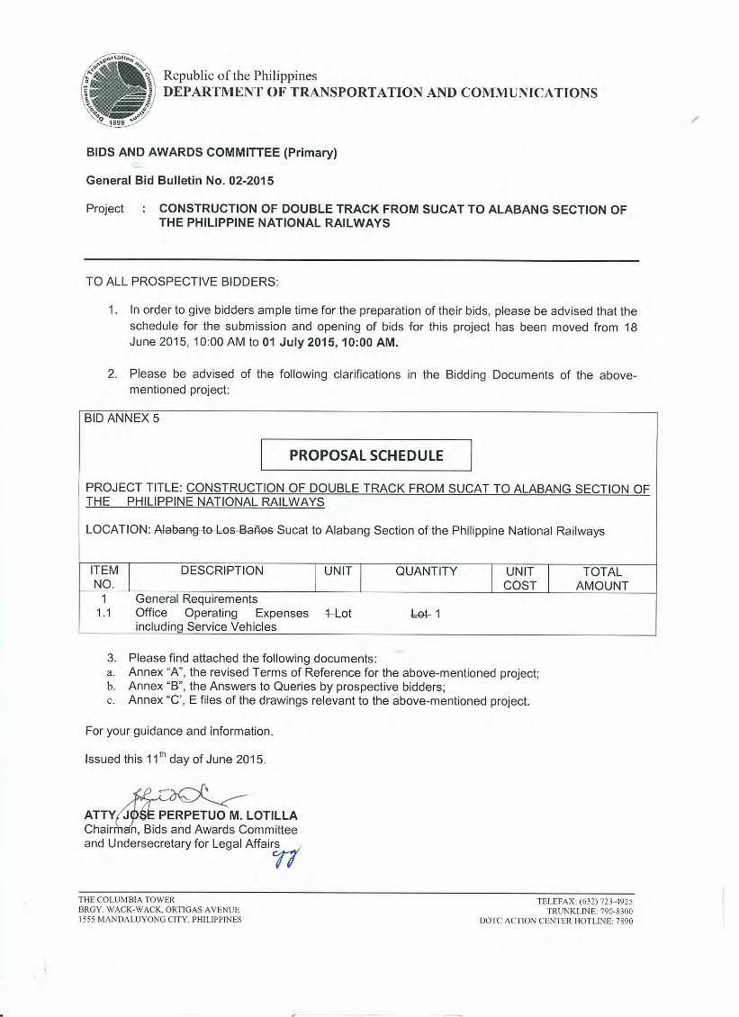
I. BACKGROUND
The Philippine National Railways Metro Manila Commuter Line has an existing line from Tutuban/Caloocan to Calamba which consist of a double railway track alignment from Tutuban/Caloocan to Sucat and a single railway track alignment from Sucat to Calamba. At present PNR is operating its commuter trains here from Tutuban to Calamba City.
In view of the demands for a cheap, safe, fast and reliable mass transport, the Philippine National Railways is embarking on a project named Double Tracking of Sucat to Alabang section. The project will redound to the reduction of travel time and increase train operation‟s capacity.
II. THE PROJECT
The project involves the construction of new track from Sucat to Alabang for the following items of works but not limited to:
1. Earthworks – Clearing and grubbing, disposal of excavated unsuitable materials and embankment formation of double track from Sucat Station to Alabang Station including a 300m each station yard at Sucat and Alabang Station inclusive of the required survey works. Construction/installation of Embankment and Ballast wall protection at 2,200 linear meter each.
2. Drainage and Slope Protections – Supply and install concrete lined ditch, U-type ditch and catch basin on locations to be designated by the Engineer.
3. Trackworks – Supply and install track ballast, 20meter-37kg rails including trackbolts and angle bars, #10 x 37kg Turnouts and switch ties, pre-stressed concrete sleepers with rail fastening, wood joint ties with trackspikes and thermit weldings and all other necessary works.
4. Bridge - Design of One (1) Bridge Slab Deck using E35 Cooper Loading at Alabang including construction of this Superstructure consisting of the supply/delivery of 2 each pre-stressed concrete girders AASHTO Type IVB, L=21.7m., 4000psi concreting works on slab with reinforcement(Vol=17.95cu.m., RSB 4,343.84kgs.), bearing pad & accessories (4 ea. elastomeric bearing pads, 200mm x 600mm x 50mm), 0.08 cu.m. Non-shrink mortar, 2.4mts 75mm dia. PVC Pipe, 3.2sq.m. premolded expansion joint filler, scaffolding and other works and materials to complete.
5. Fencing – Supply and install solid fence and see thru fence including survey works and all coordination on the PNR Right of Way on both sides of the tracks (South and North bound).
6. Level Crossing – Demolition of existing road crossings affected by the double tracking including its disposal on locations to be designated by the Engineer, supply and install asphalt pavement overlay after laying of tracks, railroad crossing lines, installation of two (2) crossing cabins with manual crossing barriers and other related works.
7. Demolition of Old Alabang Station – Demolition of Old Station, clearing & grubbing, hauling and disposal of demolished materials, preparation of embankment for

ANNEX “A”
7
earthworks and trackworks, turn-over of reusable materials to PNR and other works to complete the project.
8. Construction drawings shall first be prepared by the Contractor and submitted as draft for review and approval of the Project Engineer and Project Manager. If approved it will be submitted in a standard size tracing paper for GFC Stamping and signature of Project Engineer and Project Manager prior to any actual constructions.
9. All measurement for payment shall be referred to in the Bill of Quantities, thus all other works not specified herein shall be deemed incidental for payment and have been considered by the contractor in his unit cost estimate for the completion of the project.
10. Site Investigation information -The Contractor shall be deemed to have acquired and considered the information critical during the preparation of his bid and have carried out such further tests as he may consider necessary. No claims for additional payment will be considered from the Contractor on the grounds that the information acquired from the Engineer is incorrect or misleading.
11. No work that will in any way adversely affect train operations shall be started until adequate provision, satisfactory to the Engineer, has been made to allow trains to operate safely and punctually. No train operations shall be hampered by the Contractor except by written permission from the Engineer. This condition is further explained under the General Obligations of the Contractor.
12. The contractor shall ensure that the line is clear from any obstructions that might cause accidents/derailments. The contractor will be liable for any untoward incidents that might occur during the project implementation caused by these obstructions during his daytime and/or nighttime works.
13. As soon as an award has been made for the project, the contractor shall post a tarpaulin signboard suitably framed for outdoor display at the project location. The location will be as instructed by the Engineer. The design and format of the tarpaulin shown below shall have the following specifications: (as per COA Circular No. 2013-004).
Tarpaulin , white, 8ft x 8ft Font Size : Main Information - 3” Resolution : 70 dpi Sub-information – 1” Font : Helvetica Font Color – Black

ANNEX “A”
8
PHILIPPINE NATIONAL RAILWAYS PNR Executive Bldg., Mayhaligue St., Tutuban,Tondo, Manila, Philippines
Project : _____________________________ Cost: ________________ Location: ____________________________ Fund Source/s_________ Implementing Agency : Philippine National Railways Development Partner/s_______________________________________ Contractor/Supplier : ________________________________________ Brief Description of the Project : _______________________________ Project Details :
Project Date Project Status Remarks
Duration Started Target Date of Completion
Percentage of Completion
As of (Date)
Cost Incurred to Date
Date Completed
For particulars or complaints about this project, please contact the Regional Office or Cluster which has audit jurisdiction on this project: COA Regional Office No./Cluster ______________________ Address : _________________________________________ Contact No. : __________or Text COA Citizen‟s Desk at 0915-5391957 Note: 1. The above form shall be filled-up by the Contractor in coordination with the PNR‟s Representative. It shall be maintained as current as possible and updated as instructed by the Engineer. 2. No additional payment will be measured for this works since the cost related herein are included in the Contractor‟s detailed estimate for contingencies.
ANNEX “A”
9
PART 1 GENERAL REQUIREMENTS
1.1 GENERAL
1.1.1 SCOPE OF SPECIFICATIONS
The Specifications define the general requirements for the quality and control of materials and workmanship for the satisfactory completion of the work herein described in the following Sections.
1.1.2 COORDINATION OF SPECIFICATIONS WITH OTHER CONTRACTDOCUMENTS
These Specifications shall be read in conjunction with the other contract documents. In case of ambiguities or discrepancies, the Specifications shall have precedence over the Drawings and/or as instructed/resolved by the Engineer. Any specifications for the works not specified herein shall be referred to a standard specification and/or approved by the Engineer.
1.1.3 SITE INVESTIGATION INFORMATION
The Contractor shall be deemed to have acquired and considered the information critical during the preparation of his bid and have carried out such further tests as he may consider necessary. No claims for additional payment will be considered from the Contractor on the grounds that the information acquired from the Engineer is incorrect or misleading.
1.1.4 REFERENCE IN SPECIFICATION
Reference to standard specifications such as AREA, ASTM or AASHTO shall in every case be deemed to include the latest edition or issue of such specifications. Such specifications are referred to by abbreviations, for example AASHTO T 193 means the Standard Specifications for concrete aggregates.
References to parts, items, clauses or paragraphs which appear in the following text, but which have no title, shall be parts, items, clauses or paragraphs in the Specifications.
1.1.5 TESTING
The testing methods and procedures shall be in accordance with ASTM unless otherwise specified in the particular Section of this Specification or as shown on the Drawings and as may be directed by the Engineer in writing. When samples of materials are to be taken for testing, the methods to be utilized are fully described in the ASTM and shall be followed unless described in this Specification or referred to in this Specification to other standards or as directed in writing by the Engineer.
ANNEX “A”
10
Any material which does not conform to the requirements of these Specifications will be rejected whether in place or not. Such material shall be removed immediately from the Site at the Contractor‟s expense.
1.1.6 STANDARDS
In the specifications, references are made to the standards issued by the following organizations and referred to by abbreviations shown.
AREA - American Railway Engineering Association
AASHTO - American Association of State Highways and Transportation Officials
ANSI - American National Standards Institute
ASTM - American Society for Testing and Materials
AWS - American Welding Society
AISC - American Institute of Steel Construction
AISI - American Iron and Steel Institute
ACI - American Concrete Institute
JIS - Japanese Industrial Standard
PS - Philippine Standard
SSPC - Steel Structure Painting Council
Where one of the above standards is referred to the corresponding other standards listed above it shall be considered to be equally applicable, provided that performance and functions of materials, or workmanship or methods of tests, etc., are equal to or better than those specified in the referred standards and provided that the quantity of the works will not be increased on account of the compliance to with the new standard.
The Contractor shall submit proof that, when a standard other than that specified is proposed, it is in fact equal to or better than the specified standard. Such reference shall in every case be considered to be made to the latest edition of the said references.
1.1.7 UNITS OF MEASUREMENT
Throughout the Contract, whenever practicable, the International System of Units (SI) has been used. Where not practicable, other customary units have been used like for instance the units board foot/feet (bf).
Measurement and payment shall be as specified only in the Bill of Quantities.
ANNEX “A”
11
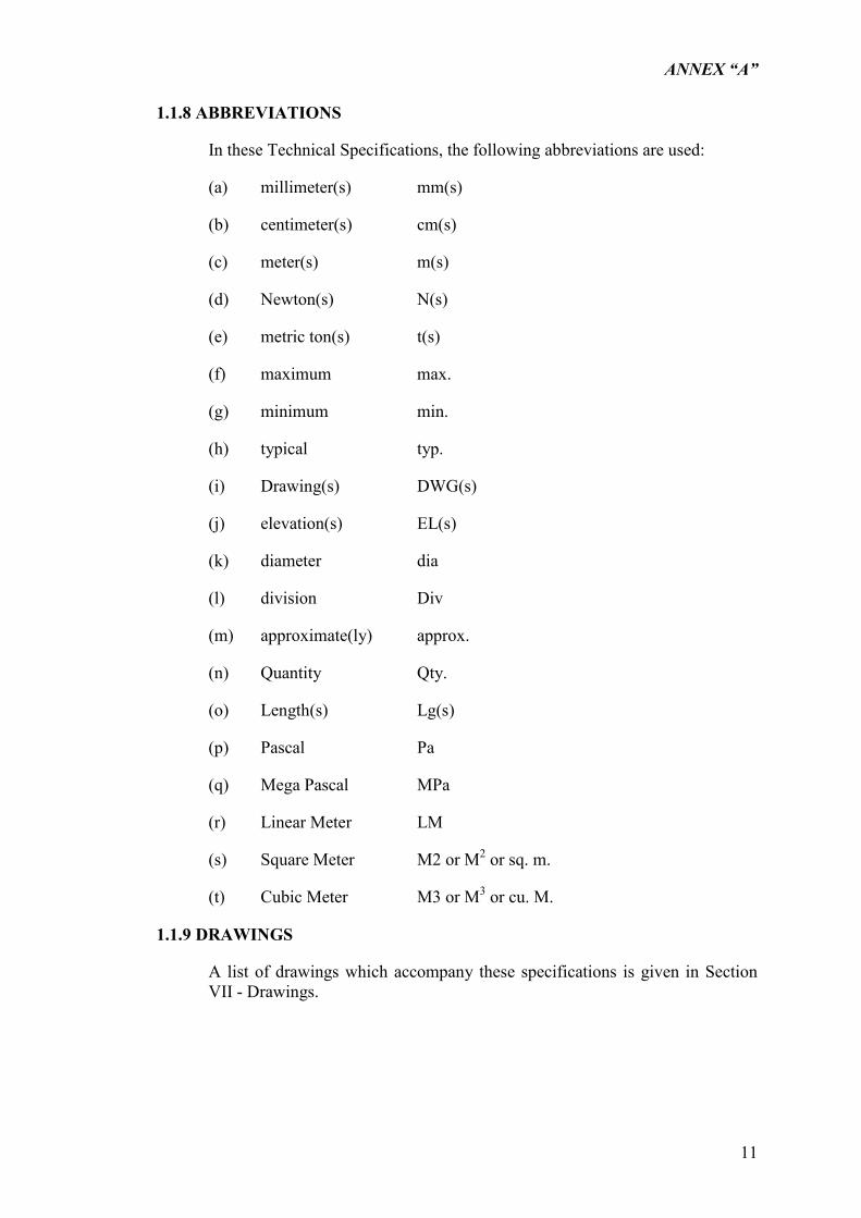
1.1.8 ABBREVIATIONS
In these Technical Specifications, the following abbreviations are used:
(a) millimeter(s) mm(s)
(b) centimeter(s) cm(s)
(c) meter(s) m(s)
(d) Newton(s) N(s)
(e) metric ton(s) t(s)
(f) maximum max.
(g) minimum min.
(h) typical typ.
(i) Drawing(s) DWG(s)
(j) elevation(s) EL(s)
(k) diameter dia
(l) division Div
(m) approximate(ly) approx.
(n) Quantity Qty.
(o) Length(s) Lg(s)
(p) Pascal Pa
(q) Mega Pascal MPa
(r) Linear Meter LM
(s) Square Meter M2 or M2 or sq. m.
(t) Cubic Meter M3 or M3 or cu. M.
1.1.9 DRAWINGS
A list of drawings which accompany these specifications is given in Section VII - Drawings.
ANNEX “A”
12
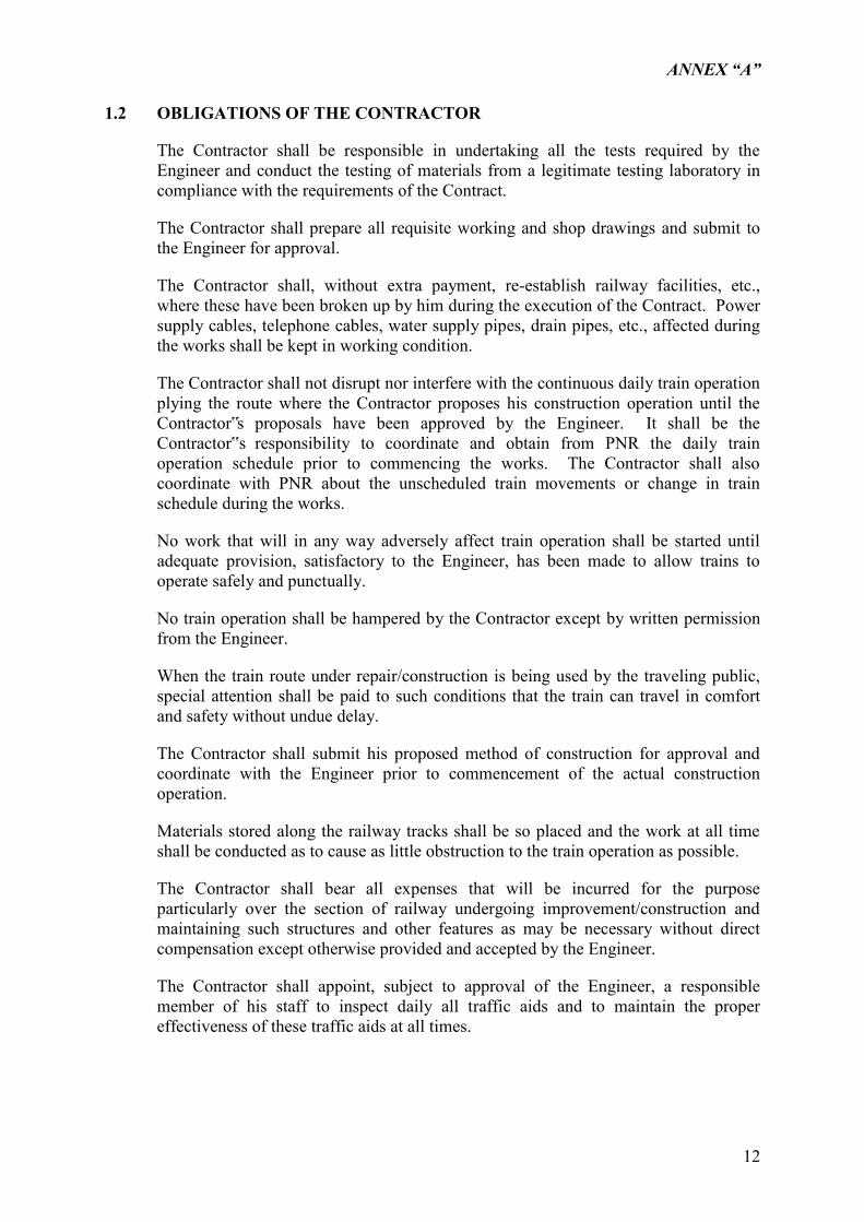
1.2 OBLIGATIONS OF THE CONTRACTOR
The Contractor shall be responsible in undertaking all the tests required by the Engineer and conduct the testing of materials from a legitimate testing laboratory in compliance with the requirements of the Contract.
The Contractor shall prepare all requisite working and shop drawings and submit to the Engineer for approval.
The Contractor shall, without extra payment, re-establish railway facilities, etc., where these have been broken up by him during the execution of the Contract. Power supply cables, telephone cables, water supply pipes, drain pipes, etc., affected during the works shall be kept in working condition.
The Contractor shall not disrupt nor interfere with the continuous daily train operation plying the route where the Contractor proposes his construction operation until the Contractor‟s proposals have been approved by the Engineer. It shall be the Contractor‟s responsibility to coordinate and obtain from PNR the daily train operation schedule prior to commencing the works. The Contractor shall also coordinate with PNR about the unscheduled train movements or change in train schedule during the works.
No work that will in any way adversely affect train operation shall be started until adequate provision, satisfactory to the Engineer, has been made to allow trains to operate safely and punctually.
No train operation shall be hampered by the Contractor except by written permission from the Engineer.
When the train route under repair/construction is being used by the traveling public, special attention shall be paid to such conditions that the train can travel in comfort and safety without undue delay.
The Contractor shall submit his proposed method of construction for approval and coordinate with the Engineer prior to commencement of the actual construction operation.
Materials stored along the railway tracks shall be so placed and the work at all time shall be conducted as to cause as little obstruction to the train operation as possible.
The Contractor shall bear all expenses that will be incurred for the purpose particularly over the section of railway undergoing improvement/construction and maintaining such structures and other features as may be necessary without direct compensation except otherwise provided and accepted by the Engineer.
The Contractor shall appoint, subject to approval of the Engineer, a responsible member of his staff to inspect daily all traffic aids and to maintain the proper effectiveness of these traffic aids at all times.
ANNEX “A”
13
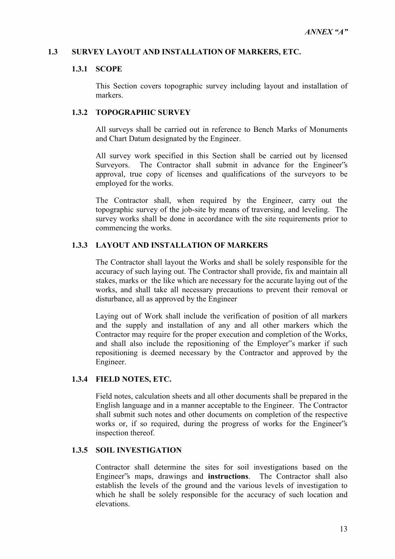
1.3 SURVEY LAYOUT AND INSTALLATION OF MARKERS, ETC.
1.3.1 SCOPE
This Section covers topographic survey including layout and installation of markers.
1.3.2 TOPOGRAPHIC SURVEY
All surveys shall be carried out in reference to Bench Marks of Monuments and Chart Datum designated by the Engineer.
All survey work specified in this Section shall be carried out by licensed Surveyors. The Contractor shall submit in advance for the Engineer‟s approval, true copy of licenses and qualifications of the surveyors to be employed for the works.
The Contractor shall, when required by the Engineer, carry out the topographic survey of the job-site by means of traversing, and leveling. The survey works shall be done in accordance with the site requirements prior to commencing the works.
1.3.3 LAYOUT AND INSTALLATION OF MARKERS
The Contractor shall layout the Works and shall be solely responsible for the accuracy of such laying out. The Contractor shall provide, fix and maintain all stakes, marks or the like which are necessary for the accurate laying out of the works, and shall take all necessary precautions to prevent their removal or disturbance, all as approved by the Engineer
Laying out of Work shall include the verification of position of all markers and the supply and installation of any and all other markers which the Contractor may require for the proper execution and completion of the Works, and shall also include the repositioning of the Employer‟s marker if such repositioning is deemed necessary by the Contractor and approved by the Engineer.
1.3.4 FIELD NOTES, ETC.
Field notes, calculation sheets and all other documents shall be prepared in the English language and in a manner acceptable to the Engineer. The Contractor shall submit such notes and other documents on completion of the respective works or, if so required, during the progress of works for the Engineer‟s inspection thereof.
1.3.5 SOIL INVESTIGATION
Contractor shall determine the sites for soil investigations based on the Engineer‟s maps, drawings and instructions. The Contractor shall also establish the levels of the ground and the various levels of investigation to which he shall be solely responsible for the accuracy of such location and elevations.
ANNEX “A”
14
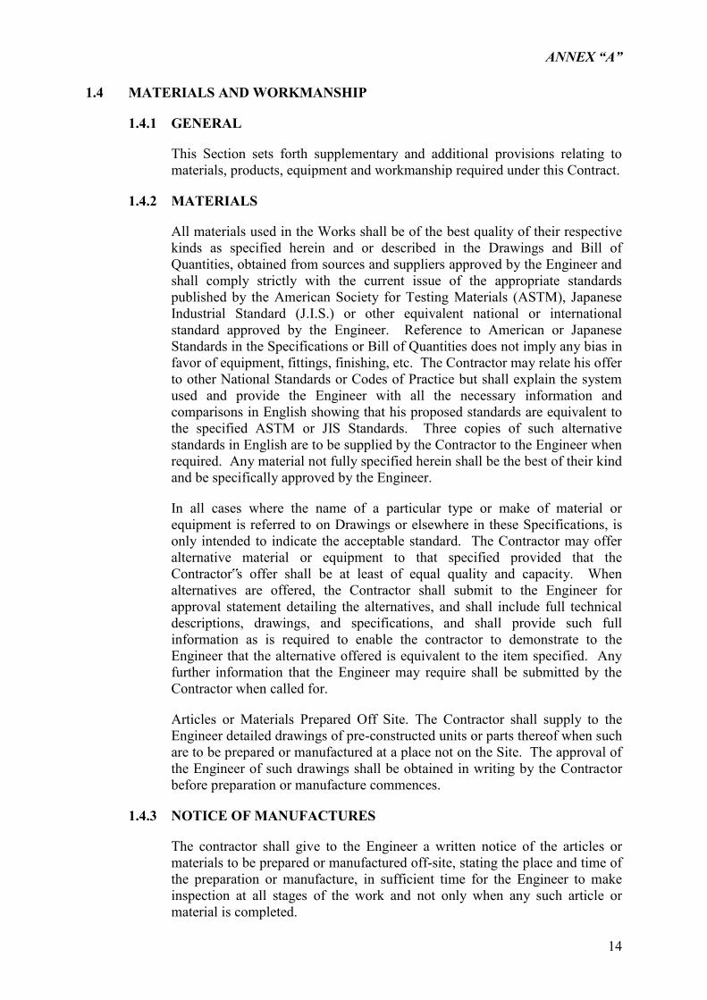
1.4 MATERIALS AND WORKMANSHIP
1.4.1 GENERAL
This Section sets forth supplementary and additional provisions relating to materials, products, equipment and workmanship required under this Contract.
1.4.2 MATERIALS
All materials used in the Works shall be of the best quality of their respective kinds as specified herein and or described in the Drawings and Bill of Quantities, obtained from sources and suppliers approved by the Engineer and shall comply strictly with the current issue of the appropriate standards published by the American Society for Testing Materials (ASTM), Japanese Industrial Standard (J.I.S.) or other equivalent national or international standard approved by the Engineer. Reference to American or Japanese Standards in the Specifications or Bill of Quantities does not imply any bias in favor of equipment, fittings, finishing, etc. The Contractor may relate his offer to other National Standards or Codes of Practice but shall explain the system used and provide the Engineer with all the necessary information and comparisons in English showing that his proposed standards are equivalent to the specified ASTM or JIS Standards. Three copies of such alternative standards in English are to be supplied by the Contractor to the Engineer when required. Any material not fully specified herein shall be the best of their kind and be specifically approved by the Engineer.
In all cases where the name of a particular type or make of material or equipment is referred to on Drawings or elsewhere in these Specifications, is only intended to indicate the acceptable standard. The Contractor may offer alternative material or equipment to that specified provided that the Contractor‟s offer shall be at least of equal quality and capacity. When alternatives are offered, the Contractor shall submit to the Engineer for approval statement detailing the alternatives, and shall include full technical descriptions, drawings, and specifications, and shall provide such full information as is required to enable the contractor to demonstrate to the Engineer that the alternative offered is equivalent to the item specified. Any further information that the Engineer may require shall be submitted by the Contractor when called for.
Articles or Materials Prepared Off Site. The Contractor shall supply to the Engineer detailed drawings of pre-constructed units or parts thereof when such are to be prepared or manufactured at a place not on the Site. The approval of the Engineer of such drawings shall be obtained in writing by the Contractor before preparation or manufacture commences.
1.4.3 NOTICE OF MANUFACTURES
The contractor shall give to the Engineer a written notice of the articles or materials to be prepared or manufactured off-site, stating the place and time of the preparation or manufacture, in sufficient time for the Engineer to make inspection at all stages of the work and not only when any such article or material is completed.
ANNEX “A”
15
Any article or material which is prepared or manufactured without giving such prior written notice to the Engineer may be rejected if the Engineer considers that inspection was necessary during the progress of the preparation or manufacture.
1.4.4 WORKMANSHIP
All workmanship shall be of the best quality appropriate to each category of work in the light of internationally recognized standards of practice. During its progress, and upon completion, the Works shall conform to the lines, elevations, and grades as shown on the Drawings. The Contractor shall complete the proposed Works in every detail as specified. However, should there be any detail or details omitted from the Drawings or Specifications which are essential to the intended completeness of any work, then it shall be the responsibility of the Contractor to furnish and install such details, subject to approval by the Engineer. Any work or workmanship not conforming to the best practices shall be subject to rejection.
1.4.5 MEASUREMENT AND PAYMENT
The requirements under materials and workmanship are incidental to other items of work and will not be measured for payment.
ANNEX “A”
16
1.5 PROGRAM OF WORK
1.5.1 DESCRIPTION
The Contractor shall within seven (7)) calendar days from the date of the Letter of Acceptance, submit to the Employer thru the Engineer a detailed working program including among others, Gantt Chart/S-Curve and PERT-CPM schedule. The program shall, in every respect, comply with the stipulations regarding the sequence of work stated in the Contract Documents.
All works shall be completed within the Contract Period stated in the Contract and by elaborating the program, due attention shall be made to all measures which reasonably can be taken in the order to diminish the inconvenience (for the common railway traffic) and to coordinate, when required, concurrent labor operation. The work program shall be approved by the Engineer before the work starts.
ANNEX “A”
17
1.6 TEMPORARY WORKS
This Section sets forth supplementary and additional provisions relating to preparatory works, facilities and safeguards required for execution of works for this Contract.
1.6.1 GENERAL PROVISIONS
The Contractor shall be responsible for temporary works, facilities and safeguards specified or required under the Contract.
The Contractor shall select, arrange for, and if necessary pay for the use of sites for detours, for all central mixing plants for concrete and for the storage of equipment, for office buildings, housing, or other uses necessary to the prosecution of the work:
Before any land belonging to the Employer or to a private landowner is used for any purpose in connection with the prosecution of the Work, the Engineer‟s approval shall be obtained.
If any utility for water, electricity, drainage, etc., passing through the site will be affected by the Works, the contractor shall provide a satisfactory alternative utility in full working order to the satisfaction of the owner of the utility and the Engineer, before the cutting of the existing utility.
Temporary Works shall be adequate for intended uses and for all loads imposed without excessive settlement, deflection or deformation. All parts and members shall be properly supported, wedged, braced and secured to prevent displacement or failure.
Temporary and permanent utilities used for construction shall be adequate for intended uses and not to be overloaded or otherwise used or arranged in any manner which will endanger persons, properties and premises of the Works. Connections shall be properly made, lines and wirings securely anchored in place, and protected against accidents.
Upon completion of the Works, unless otherwise required or directed, all preparatory structures, installations and utility services shall be disconnected and removed from the Site.
1.6.2 RIGHT-OF-WAY
The right-of-way is the strip of land acquired for and devoted to the railway. The right-of-way widths shown on the drawings are approximate only; the effective widths will be established by the Engineer.
1.6.3 TEMPORARY UTILITIES AND SERVICES
Water: The Contractor shall provide and maintain the necessary pumps, valves, motors, storage tanks or reservoir and distribution lines to adequately supply water for the Project.
ANNEX “A”
18
a) Drinking Water: Provide and maintain canister, coolers or connected drinking fountains, of sufficient number to reasonable serve the Project.
b) Construction Water: Provide and maintain temporary water service and distribution of adequate capacity for construction purposes. Include portable units, lines extensions, hoses, valves, etc., as necessary.
c) Electricity: The Contractor shall provide and maintain supply of electricity, including a stand-by generator of adequate capacity, to reasonably serve the Project.
(1) Provide and maintain temporary electric service and distribution of adequate capacity for power, lighting, and other construction needs including wiring, transformers, safety devices, connections, etc., as necessary.
(2) Provide temporary lighting as necessary to properly and safely perform work at enclosed spaces or under hazardous conditions. Likewise, provide lights for night protection as necessary.
(3) Temporary electrical system shall comply with the Philippine Electrical Code. The Employer will assist the contractor to secure the necessary power source and permit prior to the temporary installation of electric service to site. However, the cost of installation, permits and other related works for this purpose shall be borne by the Contractor.
d) The Contractor shall undertake or arrange for the regular daily clean-up and removal of trash, waste, construction debris, etc., from the Site and Temporary Work Yard to disposal areas designated by the Engineer or in accordance with local Codes and Regulations.
1.6.4 FIRST-AID AND FIRE PROTECTION
Emergency Calls: Determine locations of nearest available police, hospital or medical services and maintain their list at the Contractor‟s Site Office. The copied list shall be furnished to the Engineer.
Fire Protection
a) Establish appropriate emergency routes and procedures and submit plan to the Engineer.
b) Maintain fire extinguishers and other facilities necessary for reasonable fire protection deterrent action at the Site and Temporary Work Yard.
Minor Injuries: Provide and maintain at the Contractor‟s Site Office reasonable bandage and sterilant materials for first-aid treatment of minor injuries.
ANNEX “A”
19
1.6.5 CONSTRUCTION SAFEGUARDS
Trenches intersecting thoroughfares shall be provided with bridges or other crossing with railings, as necessary, suitable for safely carrying the type of traffic involved.
Open shafts, ramps, platforms and other such conditions shall be protected by sturdy barricades or railings.
Scaffolds, ladders ramps, hoists, and other facilities shall be provided, maintained and operated as necessary.
Storage and shop areas shall be provided, arranged and maintained at approved locations as necessary to properly store, handle and fabricate the various materials and equipment required.
1.6.6 ACCESS
The Contractor shall provide and maintain adequate access to the Project Site and all areas related to the Works.
(1) The Contractor shall provide, maintain, and remove on completion of the works for which they are required adequate access to the Project Site including sleepers, tracks, and stagings over roads, access and service roads, temporary crossings or bridges over streams or unstable ground, and he shall make them suitable in every respect for carrying all Constructional Plant required for the Work, for providing access and traffic for himself or others, or for any other purpose. Such temporary road works shall be constructed to the satisfaction of the Engineer, but the Contractor shall nevertheless be responsible for any damage done to or used by such temporary road works.
(2) Before constructing temporary road works, the Contractor shall make all necessary arrangements, including payment if required, with the public authorities or landowners concerned, for the use of the land, and he shall obtain the approval of the Engineer. Such approval will not, however, relieve the contractor of his responsibility. Upon completion of the Works, the contractor shall clean up and restore the land to the satisfaction of the Engineer or the landowner concerned. If existing roads will be used for access to the Site, the Contractor shall maintain such road for the duration of its use.
The Contractor shall make all arrangements necessary to permit the passage along the railway section relating to this Contract of the Constructional Plants, materials and employees belonging to other Contractors engaged in the construction of contiguous stretches of railway (if any). For this purpose the Contractor and the Contractors concerned in the construction of the stretches contiguous to those through which they pass shall, when necessary and with at least 15 days notice, request the Engineer for permission to pass and submit a schedule for passage. After the Engineer has granted such permission and approved the schedule submitted, both the Contractors permitting the passage and those requesting it shall undertake to observe the schedule approved by the Engineer for the passage along the site without any
ANNEX “A”
20
right to extra payment in consequence of the restrictions on passage or the necessary temporary suspension of works due to the aforesaid schedule.(3)
1.6.7 TEMPORARY TRAFFIC RAMPS
In cases where it is necessary or required by the Engineer, the Contractor shall construct and maintain temporary traffic ramps, and furnish all the labor and materials required thereof.
1.6.8 TEMPORARY TRAFFIC CONTROL
a) In order to facilitate traffic through or around the Works, or whenever ordered by the Engineer, the Contractor shall erect and maintain at prescribed points on the work and at the approaches to the work, traffic signs, lights, flares, barricades and other facilities as required by the Engineer for the direction and control of traffic.
b) Where required, or where directed by the Engineer, the Contractor shall furnish and station competent flagmen whose sole duties shall consist in directing the movement of traffic through or around the work.
(c) In addition to the requirements of (1) and (2) above, the Contractor shall furnish and erect, within or in the vicinity of the project area, such warning and guide signs as may be ordered by the Engineer.
1.6.9 PROTECTION OF DRAINAGE STRUCTURES, ACCESS ROAD, ETC.
1) In the movement of the Contractor‟s equipment and/or material from one portion of the work to another on the existing road or bridges, spillage resulting from haulage operation shall be removed immediately at the Contractor‟s expense.
2) The Contractor shall assume all cost of constructing any and all temporary bridges and accessory features, and the removal of the same after the completion of the project.
3) The Contractor shall carry out all temporary control measures as shown on the plans or ordered by the Engineer during the life of this contract to control soil erosion and water pollution to protect the existing structures as well as new structures to be provided under this contract, through use of beams, dikes, dams, sediment basins, fiber mats, netting, gravel, mulches, grasses, slope drains, and other erosion control devices or methods. The temporary erosion control provisions shall be coordinated with the permanent erosion control features specified elsewhere in the contract to the extent practical to assure economical, effective and continuous erosion control throughout the construction and post construction period. At the pre-construction conference or prior to the start of the applicable construction, the Contractor shall submit for acceptance his schedules for accomplishment of temporary and permanent erosion control work, as are applicable for bridges and other structures at watercourses, lakes, ponds or other areas of water impoundment.
ANNEX “A”
21
1.6.10 EXTRAORDINARY TRAFFIC
The Contractor is responsible for carrying out any necessary investigations and the obtaining of approvals, licenses, escorts and any other necessary facilities in order to enable extraordinary traffic to be moved on the roads in the project area. Any expenses arising out of this requirement shall be deemed to have been included in other item of works.
1.6.11 MAINTENANCE AND PROTECTION OF TRAFFIC
The Contractor shall keep the existing road open to traffic during the performance of the works, provided that when approved by the Engineer the Contractor may bypass traffic over a detour.
The contractor shall take necessary care at all times during the execution of the works to ensure the existing convenience and safety of residents along and adjacent to the road, and any public highway that may be affected by the Works. Any failure of the Contractor to meet this requirement will entitle the Engineer to carry out such work as he deems to be necessary and to charge the Contractor with the full cost thereof plus ten percent of such cost, which sum will be deducted from any money due or which may become due to the Contractor under the Contract. The Engineer shall indicate the number and type of road crossings involve in this Project.
1.6.12 PARKING
The parking space if any for use of vehicles for the project shall be maintained by the Contractor.
1.6.13 PROTECTION
The Contractor shall provide barricades as necessary for public protection.
1.6.14 COMMUNICATION FACILITIES
The Contractor shall provide telephone between jobsite and Engineer‟s/ Contractor‟s Office.
1.6.15 MEASUREMENT AND PAYMENT
1.6.15.1 Temporary works
The requirements under Temporary Works are incidental to other items of work and will not be measured for payment.
ANNEX “A”
22
1.7 TEST AND INSPECTIONS
1.7.1 GENERAL
This Section sets forth general provisions regarding tests and inspections required under this Contract.
1.7.2 FIELD LABORATORY
The Contractor shall provide all the necessary testing of materials from legitimate testing laboratory as approved by the Engineer and where laboratory tests specified under various sections of the Specifications shall be carried out, all at the Contractor‟s expense.
1.7.3 TESTS
The Contractor shall carry out all tests required under the various Sections of the Specifications in the presence and under the supervision of the Engineer.
All tests shall generally be carried out in accordance with the requirements and procedures of the referred standards for the Engineer‟s approval.
The tests shall be considered as particularized if the purpose or normal title such tests are specified.
1) For the estimation purpose, the requirements of ASTM, AASHTO, JIS or similar standards shall be taken into account.
2) Where the tests are specified to be carried out in a manner directed by the Engineer, the requirements of the above mentioned standards for similar tests shall be taken into account for estimation purpose and the tests shall be considered also as specified.
Unless otherwise expressly stated, all tests and the works in connection therewith shall be considered as incidental to the Permanent Works which require such tests and all costs thereof shall be deemed to be included in and covered by Pay Items as shown in the Bill of Quantities.
1.7.4 TEST AT THE SITE
Notwithstanding any previous inspections and tests, all materials delivered to the Site shall be subject to examinations and tests, if so directed by the Engineer. Should such test be desired by Engineer, Contractor will be advised in sufficient time to permit such testing.
1) All such examinations and tests shall be carried out by the Contractor at his cost in the presence of the Engineer in accordance with the normal practice in respect of such examinations and tests if the same may be carried out by the Contractor with his staff and equipment available at the Site.
2) Otherwise, the tests shall be made at a laboratory by the Engineer at the cost to the Contractor.
ANNEX “A”
23
The Engineer shall be at liberty to reject any materials which do not comply with the requirements of the Contract notwithstanding any previous approval thereof.
The Contractor shall not be entitled to any extra payments or extension of time for completion of the Works on account of the rejection of materials due to their non-compliance with the requirements of the Contract or of the waiting time reasonably required for carrying out the examinations and tests.
The Contractor shall furnish test samples as instructed and shall provide reasonable assistance and cooperation as necessary to permit tests to be performed on materials or work in place including reasonable stoppage of Work during testing.
1.7.5 MEASUREMENT OF PAYMENT
Unless otherwise expressly stated, all tests and the works in connection therewith shall be considered as incidental to the Permanent Works which required such tests and all costs thereof shall be deemed to be included in and covered by the Pay Items as shown in the Bill of Quantities.
ANNEX “A”
24
1.8 SUBMITTALS
1.8.1 GENERAL
This Section sets forth general provisions regarding submittals required of the Contractor.
The Contractor shall submit to the Engineer all construction schedules, monthly progress reports, final construction report, statement of completion, final statement, survey data, shop drawings, as-built drawings, product data, samples, and construction photographs as specified.
Until submittal is reviewed by the Engineer, approved and released for distribution, work involving relevant product data may not proceed.
Engineer‟s review will be signified by comments as required identifying items for resubmission and by stamp of Engineer when work is released for distribution.
1.8.2 CONSTRUCTION SCHEDULES, SURVEY DATA AND SHOP DRAWINGS
Schedules, data, field drawings and shop drawings shall be originally prepared by Contractor, Sub-Contractor, Supplier or Distributor which shall illustrate appropriate portions of work. The work items shall be described in relation to responsibility, fabrication, layout, setting or erection details as specified in appropriate Sections.
Submittal drawings to be reproducible transparency with one opaque print.
Maximum sheet size is 610mm x 1070mm (23.5 in. x 33 in.)
1.8.3 PRODUCT DATA
Certain Sections of the Specifications state that manufacturer‟s standard schematic drawings, catalogue sheets, diagrams, schedules, performance charts, illustrations and other standard descriptive data will be accepted in lieu of shop drawings.
From the above and when necessary:
1) Delete information which is not applicable to the project; 2) Supplement standard information to provide additional information applicable to the project; 3) Show dimensions and clearances required; and 4) Show performance characteristics and capacities.
1.8.4 SAMPLES
Submit samples in sizes and quantities specified.
Where color is a criterion, submit full range of colors.
Construct field samples or mock-ups at locations acceptable to Engineer.
ANNEX “A”
25
Construct each sample or mock-up complete, including work of all trades required to finish work.
Reviewed and approved samples or mock-ups will become standards of workmanship and material against which, installed work will be checked on the Project.
1.8.5 CONTRACTOR’S RESPONSIBILITIES
Review shop drawings product data and samples prior to submission.
Verify:
1) Field Measurements 2) Field Construction Criteria 3) Catalogue Numbers and Similar Data Coordinate each submittal with the Project requirements and Contract Documents.
Contractor‟s responsibility for errors and omissions on submittals is not relieved by Engineer‟s review of submittals.
Contractor‟s responsibility for deviations on submittals from requirements of Contract Documents is not relieved by Engineer‟s review of submittals, unless Engineer gives written acceptance of specified deviations.
Notify Engineer, in writing at time of submission, of deviation on submittals from requirements of Contract Documents.
After Engineer‟s review, distribute copies.
The Contractor shall schedule submissions at least 5 working days before dates reviewed submittals will be needed.
The Contractor shall submit one (1) reproducible transparency and one opaque print of schedules, survey data and shop drawings, and number of copies of project data which Contractor requires for distribution plus four (4) copies which will be retained by Engineer.
The Contractor‟s submittals shall be accompanied with transmittal letter, in duplicate copies, containing:
1) Date 2) Project title and number 3) Contractor‟s name and address 4) Number of each shop drawing, product data and sample 5) Other pertinent data Submittals shall include: 1) Data and revision dates 2) Project title and number 3) Name of - Contractor - Sub-Contractor
ANNEX “A”
26
- Supplier - Manufacturer - Separate retailer when pertinent 4) Identification of product or material 5) Relation to adjacent structure or material 6) Field dimensions, clearly identified as such 7) Specifications Section Number 8) Applicable standards, such as ASTM, JIS numbers 9) Contractor‟s stamp, initialed or signed, certifying review of submittal, verification of field measurements and compliance with Contract Documents
1.8.6 DISTRIBUTION OF SUBMITTALS AFTER REVIEW
Distribute copies of shop drawings and product data which carry Engineer‟s stamp, to: 1) Job-site file 2) Record documents file 3) Sub-Contractors 4) Suppliers 5) Fabricators As appropriate in each case.
1.8.7 CONSTRUCTION PHOTOGRAPHS
Provide record progress photographs taken at a fixed point and angle as when and where directed by the Engineer as intervals of not more than twenty eight (28) calendar days.
The photographs shall be sufficient in number and location to record the exact progress of works. Provide one (1) proof print of each photograph taken and the negative and five (5) colored copies, 245 x 203 mm of any of the photographs selected by the Engineer. Two (2) copies are to be signed by the Contractor and the Engineer. Albums to accommodate the selected photographs shall be supplied by Contractor.
1.8.8 MONTHLY PROGRESS REPORT
The Contractor shall maintain a daily log describing the important events pertaining to the works, the working hours, the number of laborers employed, effective operation time of equipment, overtime hours, delays due to meteorological conditions, the lack of labor, materials or equipment, progress made and instructions, notifications and recommendations made by the Engineer.
The Contractor shall furnish to the Engineer ten (10) copies of the monthly progress reports within seven (7) days after the end of every month, indicating progress made, construction activities, inventories of material used and stored on jobsite numbers of labors, equipment available and hours utilized, number of working days, the summary of the daily log of the month and all important events in relation to the Works.

ANNEX “A”
27
1.8.9 AS-BUILT DRAWINGS AND FINAL CONSTRUCTION REPORT
Within twenty eight (28) calendar days after the issuance of the Taking Over Certificate, the Contractor shall prepare and submit two (2) sets of As-Built Drawings and final construction report as draft. And within fourteen (14) days after the issuance of the last Taking Over Certificate, the Contractor shall submit five (5) sets of final construction report and final As-Built Drawings. As built Drawings of the works consist of one (1) set of original size copy, one (1) set of original size reproducible, two (2) sets of reduced size copy, one (1) set of reduced size reproducible and one (1) set of electronic file, which shall be subject to approval of the Engineer.
ANNEX “A”
28
1.9 QUALITY CONTROL REQUIREMENTS
1.9.1 GENERAL
This Section sets forth supplementary and additional provisions relating to quality control and additional provisions relating to quality control and workmanship required under this Contract.
1.9.2 CONTRACTOR’S SUBMISSION
All shop drawings, certificates of compliance manufacturer‟s literature, material samples, mix design, guarantees, equipment data, and other information as called for under the various headings of these specifications shall be submitted by the Contractor as required. The adequacy and accuracy of submittals for compliance and so certify them in accordance with the quality control requirements. Except in cases where approval by the Engineer is required under the various headings of these specifications or on the Contract Drawings, certification by the Contractor that a submittal, complies with the contract requirements shall signify completion of the review process. However, the Engineer reserves the right to review and require correction of any submittal, but failure to do so shall not constitute a waiver of any requirement of the contract drawings or specifications.
a) Within twenty eight (28) calendar days after receipt of Notice to Proceed, the Contractor shall submit to the Engineer four (4) copies of submittals control document listing all submittal items. In preparing the document adequate time will be allowed for review by the Contractor‟s quality control organization and a minimum of fourteen (14) calendar days for review approval, and possible re-submittal of items for which approval by the Engineer is required and items for which deviation from the requirements of the contract drawings or specifications is proposed by the Contractor. Scheduling of submittals on the control document shall be coordinated with the approved progress schedule. All required submittals must be made in time to allow for review, certification, approval if required, procurement, delivery and preparatory inspection of the item before it is needed in construction. It is the Contractor‟s obligation to comply with the specification requirements for the items on the Schedule. The Contractor‟s quality control representative shall review the listing at least every twenty eight (28) calendar days and take appropriate action to maintain a complete and current listing. Copies of updated or corrected listing shall be submitted to the Engineer at least every twenty eight (28) calendar days in four (4) copies. Payment will not be made for any material or equipment which does not comply with contract requirements. The Contractor shall submit a preliminary submittal control document covering submittals required within the first fifty six (56) calendar days after receipt of Notice to Proceed prior to making any submittals.
b) All submittals made under this Section entitled “Shop Drawings” in a foreign language shall be accompanied by an English translation.
c) The Contractor shall maintain a complete file of all submittals which he has certified and all submittals which have also been approved by the
ANNEX “A”
29
Engineer. Upon the completion of the work under this Contract, the Contract shall furnish one complete set of prints of all shop drawings as finally certified in addition to those furnished in accordance with the Specification requirements for shop drawings. These drawings shall show changes and revisions made up to the time the Project is completed and accepted.
d) Submittal control documents and all submittals to the Engineer shall be addressed to:
The Project Manager
Project Implementation Office
PNR Executive Bldg, Mayhaligue St. Tutuban
Tondo, Metro Manila
e) The Contractor shall perform on the site, and with his own organization, work equivalent to at least fifty (50) percent of the total amount of work to be performed under the Contract. If during the progress of the work hereunder, the Contractor shall request a reduction in such percentage to the Employer through the Engineer, and the Engineer determines that it would be to the Employer‟s advantage, the percentage of the work required to be performed by the Contractor may be reduced, provided, written approval of such reduction is obtained by the Contractor from the Engineer. If the above percentage is less than 100%, the successful bidder must furnish to the engineer within fifteen (15) days after award a description of the items of work which he will perform with his own forces, the estimated cost of those items, and the percentage of total work those items represent.
The Employer will furnish to the Contractor some rails available as listed on the drawings to be incorporated or installed in the work or used in its performance. Such property will be furnished at the place shown on the drawings, and the Contractor will be required to accept delivery when made, paying any demurrage or detention charges incurred, and loading and transporting the property to the job site at his own expense. All such property will be installed or incorporated into the work at the expense of the Contractor, unless otherwise indicated herein. The Contractor shall verify the quantity and condition of such Government furnished property when delivered to him, acknowledge receipt thereof in writing to the Engineer, and in case of damage to or shortage of such property, he shall within 24 hours report in writing such damage or shortage to the Engineer.
Contractor‟s Quality Control
a) The Contractor shall provide and maintain an effective quality control program.
1) The Contractor shall establish a quality control system to review all submittals made to the Engineer in accordance with the above submission requirements, and to perform sufficient inspection and/or tests of all items of work, including that of his subcontractors, to ensure conformance to
ANNEX “A”
30
applicable specifications and drawings with respect to the materials, workmanship, construction, with emphasis on the surveillance tests and submittals required in the technical provisions of the contract specification including in plant inspection. The Contractor‟s quality control system will be established to include all construction, except where the technical provisions of the contract provide for specific Government control by inspections, tests, or other means. The Contractor‟s quality control system will be keyed to the proposed construction deficiencies. The Employer reserves the right to direct the location of the required test. Any of the test that, when performed, do not indicate compliance with contract requirements will be reported but will not be considered as a test to satisfy the required number of tests.
2) The Contractor has full responsibility for compliance with all provisions of the Contract. The burden of proof of Contract compliance is placed on the Contractor and not assumed by the Employer. The Contractor‟s quality control without question and the right to inspect or verify at any time is reserved by the Engineer.
3) The Engineer, reserves the right to inspect at the source supplies or services not manufactured or performed within the Contractor‟s facility. Engineer‟s inspection shall not constitute acceptance, or shall it in any way replace Contractor inspection or otherwise relieve the contractors, or suppliers plants is performed by the Engineer, such inspection shall not be used by Contractor as evidence of effective inspection by such subcontractors or suppliers.
4) The quality control program may be implemented by the Contractor utilizing his job supervisory staff to insure compliance with the Contract Plans and Specifications. It will be supplemented as necessary with special technicians, part-time specialty quality control men, and testing facilities to provide capability for the reviews, inspection, controls and tests required. The Contractor‟s quality control personnel shall be experienced and qualified in the specialty of work they are performing. They will report to the Engineer when required.
5) The prime Contractor‟s designated quality control representative, will be required to certify, with each submittal, that it has been reviewed in detail and that it is correct and in strict conformance with the contract drawings and specifications, except as may be otherwise explicitly stated.
6) The Contractor‟s inspection system shall for producers which will assure that the latest applicable contract drawings, specifications, certified submittals, approved submittals, and instructions required by the contract, as well as authorized changes thereto, are used for fabrication inspection and testing.
7) The Contractor shall provide and maintain all measuring and testing devices, laboratory equipment, instruments, transportation, and supplies necessary to accomplish the required testing and inspection. All measuring and testing devices shall be calibrated at established intervals against certified
ANNEX “A”
31
standards which have known valid relationships to national standards. The Contractor‟s measuring and testing equipment shall be made available for use by the Engineer for verification of their accuracy and condition as well as for any inspection or test desired.
b) The Contractor‟s quality control system at the job site shall follow a three-step procedure.
1) First, to ensure that the plant, materials, equipment, and safety auxiliaries meet the submittals and contract requirements. The Contractor will perform preparatory inspections as soon as possible after delivery of plant, equipment, and material to the site and, in any event, prior to incorporation of material and equipment in the work. The Contractor will appropriately annotate his quality control reports for all preparatory inspections with a detailed list of items of plant, equipment, and material inspected or tested, findings relative to compliance with approvals, Contractors-certified submittals and contract requirements, and actions taken where non-compliance is discovered. In addition, during preparatory inspections, the Contractor will make an examination of the work area to insure that all preliminary work has been completed, check to assure that provisions have been completed to provide required control testing, and take necessary action to insure that all plant, equipment, and material is properly stored to prevent damage from the elements and construction operations and will so note on the quality control reports. Names of all personnel who participate in each preparatory inspection will be listed on the quality control report.
2) Second, at the start of each new phase of construction to establish that methods, techniques, and standards of workmanship are in strict compliance with the contract requirements. The Contractor will appropriately annotate his quality control reports for all initial inspections to include a detailed description and location of the segment or phase of work inspected including checks, tests and measurements made to determine that quality of construction, tolerances, and workmanship standards are in strict compliance with the contract requirements. The names of personnel who participate in the initial inspection will be listed on the quality control reports.
3) Third, follow-up inspections will be performed on a daily or re-curring basis as necessary to insure that construction is proceeding in accordance with contract requirements. The Contractor‟s quality control reports will detail the results of follow-up testing, inspection, and corrective actions.
4) The Contractor‟s quality control representative will advise the Engineer at least 24 hours prior to all preparatory and initial inspections. The Engineer will participate in the preparatory and follow-up inspection.
c) The Contractor shall furnish a daily construction quality control report. The report shall be in accordance with a form as may be proposed by the Contractor and approved by the Engineer. Additional check lists and forms for specific operations may be required to supplement the daily inspection form. The report shall include all inspections and tests made. It shall provide factual evidence that the required inspections or tests have been performed, including
ANNEX “A”
32
type and number of inspections or rejection and the corrective action taken. The daily report shall cover both conforming and defective items. It shall include a statement that all materials and equipment incorporated in the work are in full compliance with the terms of the contract except as noted. The report will cover all items and specifically include the items listed in the quality control paragraphs of the technical provisions. The report will be verified and signed by the prime Contractor‟s designated quality control representative. The daily reports will be furnished in two copies (Original and one duplicate) to the Engineer at the job site. The report will be legibly handwritten in ink or typewritten. Reports shall be submitted not later than the close of business on the first working day following the date of the report. Reports shall have all supporting documents (such as concrete placement checklists, laboratory reports of compaction tests, sieve analysis, etc.) attached. Incomplete reports will not be accepted. The Contractor is responsible for insuring that test reports are prepared and attached to the daily report for the day that the test was performed. Negative reports are required for days during which there is no activity on the project site to include a brief statement as to why there was no activity during a normal workday or schedule.
d) After the contract is awarded and before field construction operations are started, the Contractor shall meet the Engineer, and discuss quality control requirements. The meeting shall develop mutual understanding relative to details of the system, including the forms to be used for recording the quality control operations, inspections, administration of the system, and the interrelationship of Contractor and Engineer inspection.
e) The Contractor will need to give consideration to his quality control plan prior to bidding. This will assist in the early submission of an acceptable plan. The Contractor will furnish to the Employer not later than fourteen (14) calendar days after receipt of Notice to Proceed, a quality control plan which will include the procedures, instructions, and reports to be used. This document will include as a minimum.
(1) The quality control organization. This will be in the form of an organization chart that shows names and specific responsibilities of each of the quality control personnel.
(2) The qualifications of each person performing submittal review and certification, and inspection will be summarized not to exceed one (1) typewritten page, giving education, present job position, and previous work experience. These may be furnished in phases as the work progresses but in no cases later than fourteen (14) calendar days before coming on the job.
(3) A copy of a letter of direction to each of the Contractor‟s quality control representatives, outlining his duties, authority, and responsibilities, and signed by a responsible officer of the firm.
(4) Proposed methods of performing quality control inspections, including those for his subcontractors‟ work.
ANNEX “A”
33
(5) Test methods to include the names and qualifications of technicians employed by the Contractor as well as specific tests to be performed by each, the names of all qualified test organization to be used, and the location and availability of test facilities and equipment.
(6) Procedures for reviewing all shop drawings, samples, certificates, etc., for contract compliance and certifying them.
(7) Method of documenting quality control operation, inspection, and testing. Including samples of proposed forms.
(8) Each copy of the complete plan will be assembled in a folder in the order listed above. Four (4) copies will be submitted for approval. Revisions to the plan will be submitted in four (4) copies.
f) Unless specifically authorized by the Engineer, no construction shall be started until the Contractor‟s quality control plan is approved. The approval will be contingent on satisfactory implementation and results. Payments will be withheld for all work until the quality control plan has been submitted and approved.
g) The Contractor shall notify the Engineer in writing of any proposed change in his quality control system or personnel. No such change will be implemented prior to acceptance by the Engineer.
1.9.3 MEASUREMENT AND PAYMENT
The requirements under this Section are incidental to other items of work and will not be measured for payment, unless otherwise specified in the Bill of Quantities.
ANNEX “A”
34
1.10 MOBILIZATION AND DEMOBILIZATION
1.10.1 SCOPE
This Section refers to the mobilization in preparation for the execution of the Works, and demobilization after completion of the Works.
1.10.2 MOBILIZATION
Mobilization includes the following:
1) Plant and Equipment
a) Assembly, preparation and loading for shipment of all plant and equipment at the Contractor‟s home station or source of supply.
b) Transportation of plant, equipment and materials from home station or source of supply to the site.
c) Unload and install, ready for use, all plant and equipment and whatever else required for the execution of the Works.
d) Maintenance of the plant and equipment during the construction which shall include providing sufficient supply of spare for the construction plant and equipment.
2) Construction of temporary site office and appurtenant facilities such as office tables, drafting table and instrument, water, power and sanitary facilities necessary for an effective and efficient execution of the work.
3) Construction of all temporary access roads for an effective and efficient execution of the Works.
4) Survey layout and installation of fixed points for the setting out of the works.
1.10.3 DEMOBILIZATION
Demobilization shall include the following:
1) The dismantling, preparation and loading for removal and shipment of all Contractor‟s plant and equipment at the Site.
Transportation of all the above plant, equipment and materials of the site to the home station or somewhere else outside the Site.2)
3) Dismantling and removing of all temporary buildings and structures.
4) Removal of all supplementary markers furnished and installed by the Contractor, provided that the Engineer has not taken the option to retain the markers.
ANNEX “A”
35
5) The clean-up of the Site and Work area, and the removal of material, debris, waste, etc., and making good damage or temporary alterations.
1.10.4 MEASUREMENT AND PAYMENT
The requirements under this Section are incidental to other items of work and will not be measured for payment.

ANNEX “A”
36
1.11 OPERATIONS AND MAINTENANCE OF OFFICE AND SERVICE VEHICLE
1.11.1 OFFICE SUPPLIES
This covers the provisions office supplies on a day to day operating expenses of the existing PNR‟s Engineer‟s office at Tutuban Manila such as common stationeries, printer‟s refillable inks and a monthly (Php1,200.00) prepaid cell cards for the period of two hundred (200) calendar days.
1.11.2 SERVICE VEHICLE
This covers the provision of service vehicle of at least 2009 model pick-up, air-con, in good running condition and updated registration on owned / lease basis including driver and twenty (20) liters of fuel per day for the exclusive use of the PNR Project Engineer supervising the project for the period of two hundred (200) calendar days. Maintenance and fuel cost for the service vehicle shall be included under this item.
ANNEX “A”
37
PART 2 EARTHWORKS
2.1 CLEARING AND GRUBBING
2.1.1 SCOPE
The clearing and grubbing shall consist of clearing of all trees, down timber, snags, brush, other vegetation, rubbish, and all other objectionable material, including grubbing stumps, roots, and disposing of all spoil material resulting from the clearing and grubbing in accordance with these Specifications or as directed by the Engineer. It shall also include the removal and disposal of structures that obtrude, encroach upon, or otherwise obstruct the works except where otherwise provided for in these Specifications or ordered by the Engineer.
2.1.2CONSTRUCTION REQUIREMENTS
2.1.2.1 General
The Engineer will establish the limits of work and designate all trees, shrubs, plants and other things to be cleared. The contractor shall preserve all objects designated to remain.
2.1.2.2 Clearing and Grubbing
All surface objects and trees, stumps, roots and other protruding obstructions, not designated to remain, shall be cleared and/or grubbed, including mowing as required, except as provided below:
1) Removal of undisturbed stumps and roots and non-perishable solid objects with a minimum of 900 mm (36 inches) below subgrade or slope of embankments will not be required.
2) In areas outside of the grading limits of cut and embankment areas, stumps and nonperishable solid objects shall be cut off not more than 150 mm (6 inches) above the ground line or low water level.
3) In areas to be rounded at the top of cut slopes, stumps shall be cut off flush with or below the surface of the final slope line.
4) Grubbing of pits, channel changes and ditches will be required only to the depth necessitated by the proposed excavation within such areas.
Except in areas to be excavated, stump holes and other holes from which obstructions are removed shall be backfilled with suitable material and compacted to the required density.
ANNEX “A”
38
If perishable material is burned, it shall be burned under the constant care of competent watchmen at such times and in such a manner that the surrounding vegetation, other adjacent property, or anything designated to remain on the right of way will not be jeopardized. If permitted, burning shall be done in accordance with applicable laws, ordinances, and regulations.
The Contractor shall use high intensity burning procedures, (i.e., incinerators, high stacking or pit and ditch burning with forced air supplements) that produce intense burning with little or no visible smoke emission during the burning process. At the conclusion of each burning session, the fire shall be completely extinguished so that no smoldering debris remains.
In the event that the Contractor is directed by the Engineer not to start burning operations or to suspend such operations because of hazardous weather conditions, material to be burned which interferes with subsequent construction operations shall be moved by the contractor to temporary locations clear of construction operations and later if directed by the Engineer, shall be placed on a designated spot and burned.
Materials and debris which cannot be burned and perishable materials be disposed off by methods and at locations approved by the Engineer, on or off the project. If disposal is by burying, the debris shall be placed in layers with the material so disturbed to avoid nesting. Each layer shall be covered or mixed with earth material by the land-fill method to fill all voids. The top layer of material buried shall be covered with at least 300 mm (12 inches) of earth or other approved material shall be graded, shaped and compacted to present a pleasing appearance. If the disposal location is off the project, the contractor shall make all necessary arrangements with property owners in writing for obtaining suitable disposal locations which are outside the limits of view from the project. The cost involved shall be included in the unit bid price. A copy of such agreement shall be furnished to the Engineer. The disposal areas shall be seeded, fertilized and mulched at the Contractor‟s expense.
Woody material may be disposed off by chipping. The wood chips may be used for mulch, slope erosion control or may be uniformly spread over selected areas as directed by the Engineer. Wood chips used as mulch for slope erosion control shall have a maximum thickness of 12 mm (1/2 inch) and faces not exceeding 3900 sq. mm. (6 sq. inches) on any individual surface area. Wood chips not designated for use under other sections shall be spread over the designated areas in layers not to exceed 75 mm (3 inches) loose thickness. Diseased trees shall be buried or disposed off as directed by the Engineer.
All merchantable timber in the clearing area which has not been removed from the right of way prior to the beginning of
ANNEX “A”
39
construction, shall become the property of the Employer, unless otherwise provided.
Low hanging branches and unsound or unsightly branches of trees or shrubs designated to remain shall be trimmed as directed. Branches of trees extending over the railway shall be trimmed to give a clear height of 6 m (20 feet) above the railway surface. All trimming shall be done by skilled workmen and in accordance with good tree surgery practices.
Timber cut inside the area staked for clearing shall be felled within the area to be cleared.
2.1.2.3 Individual Removal of Trees or Stumps
Individual trees or stumps designated by the Engineer for removal and located in areas other than those established for clearing and grubbing and roadside cleanup shall be removed and disposed off as specified under Subsection 2.1.2.2 except trees removed shall be cut as nearly flush with the ground as practicable without removing stumps.
2.1.2.4 Removal of Stumps, Roots, Topsoil, Etc.
The area occupied by the existing railway is excluded from the strip considered, and the clearing and grubbing is limited to the surface area directed by the Engineer.
In cut areas, all stumps and roots shall be removed to a depth of not less than 50 cm below the finished subgrade level.
In areas under roadbed embankments, from which topsoil or unsuitable materials are to be removed or which are designated to be compacted, all stumps and roots shall be removed to a depth of at least 90 cm below the original ground surface.
Grubbing of channels and ditches will be required only to the depth necessary for the proposed excavation within such areas.
In areas under roadbed embankments designed by the Engineer, the Contractor shall remove the topsoil and dispose of it on adjacent land as directed by the Engineer.
In general, the removal of topsoil should include only the removal of soil which is sufficiently fertile to encourage or sustain a growth of vegetation.
No removal of topsoil over any designated area shall be less than 15 cm in depth measured vertically or as directed by the Engineer, and the topsoil shall be kept separate from other excavated material.
ANNEX “A”
40
This removal of topsoil shall not be paid for separately as it is a subsidiary obligation of the Contractor in carrying out the clearing and grubbing operations.
When the topsoil will be used for dressing of the slopes of the embankment as directed by the Engineer or as indicated on the drawings, this work will be considered as formation of embankment and shall conform to the requirement of Section 2.5 of these Specifications for construction, measurement and payment. In this case the removal of topsoil will not be measured for direct payment, but will be considered as a subsidiary obligation of the Contractor covered by the Scheduled item “Embankment” with material from Common or Selected Borrow.
2.1.3 MEASUREMENT AND PAYMENT
2.1.3.1 Measurement will be by one or more of the following alternate methods:
a. Area Basis. The work to be paid for shall be the number of square meters and fractions thereof acceptably cleared and grubbed within the limits indicated on the Drawings or as may be adjusted in field staking by the Engineer. Areas not within the clearing and grubbing limits shown on the Drawings or not staked for clearing and grubbing will not be measured for payment.
b. Lump Sum Basis. When the Bill of Quantities contains a Clearing and Grubbing lump sum item, no measurement of area will be made for such item.
c. Individual Unit Basis (Selective Clearing). The diameter of trees will be measured at a height of 1.4 m (54 inches) above the ground. Trees less than 150 mm (6 inches) in diameter will not be measured for payment.
When Bill of Quantities indicates measurement of trees by individual unit basis, the units will be designated and measured in accordance with the following schedule of sizes:
Diameter at height of 1.4 m Pay Item Designation Over 150 mm to 900 mm Small Over 900 mm Large
2.1.3.2 Basis of Payment
The accepted quantities, measured as prescribed in Sub-Section 2.1.3.1 shall be paid for at the contract unit price for each of the Pay Items listed in the Bill of Quantities, which price and payment shall be full compensation for furnishing all labor, equipment, tools and incidentals necessary to complete the work prescribed in this Section.
ANNEX “A”
41
2.2 STRIPPING
2.2.1 SCOPE
This work shall consist of removing topsoil, transporting and depositing it in stockpiles and replacing and spreading it where indicated on the Drawings or where directed by the Engineer.
2.2.2 CONSTRUCTION REQUIREMENTS
The areas from which stripping of topsoil may be required shall be indicated on the Drawings. The Contractor shall remove topsoil from such portions of these areas and to such depth as the Engineer may require. No stripping of topsoil of any designated area shall be less than 150 mm in depth. The topsoil removed shall be transported, deposited in stock piles at locations approved by the Engineer, and/or spread and compacted with a light roller where indicated on the drawings or where directed by the Engineer. The topsoil shall be kept separate from other excavated materials and shall be completely removed to the required depth from any designated area prior to the beginning of regular excavation or embankment work in the area. No payment will be made for stripping the topsoil carried out in areas other than those ordered.
2.2.3 MEASUREMENT AND PAYMENT
2.2.3.1 Method of Measurement
The quantities of stripping to be paid for according to these Specifications shall be the number of square meters acceptably stripped in accordance with the instructions of the Engineer and shall be deemed to be included in the pay Item for Clearing and Grubbing.
2.2.3.2 Basis Of Payment
Unless otherwise provided in the special provisions, stripping shall not be measured and paid for separately, but the cost thereof shall be considered as included in the Contract Price for Clearing and Grubbing.
ANNEX “A”
42
2.3 EXCAVATION
2.3.1 SCOPE
Excavation shall consist of all work necessary for the excavation including placing or disposal of earth or rock or other material from or to the railway or adjacent thereto, for construction of waterways, ditches, levees and approaches for the unclassified excavation, rock excavation or muck excavation, for the removal of unsuitable material and topsoil, the removal of landslides, all in accordance with these Specifications and in reasonably close conformity with the lines, grades, shown on the drawings or as established by the Engineer.
Excavation will be classified as “unclassified excavation”, “rock excavation”, “common excavation” or “muck excavation” as indicated in the Bill of Quantities and hereinafter described.
1) Unclassified Excavation. Unclassified excavation shall consist of the excavation and disposal of all materials regardless of its nature, or not classified and included in the Bill of Quantities under other pay items.
2) Rock Excavation. Rock Excavation shall consist of igneous, sedimentary and metamorphic rock which cannot be excavated without blasting or the use of rippers, and all boulders or other detached stones each having a volume of one (1) cubic meter or more as determined by physical measurements or visually by the Engineer.
3) Common Excavation. Common excavation are those not included in the Bill of Quantities under “rock excavation” or other pay items.
4) Muck Excavation. Muck excavation shall consist of the removal and disposal of deposits of saturated or unsaturated mixtures of soils and organic matter not suitable for foundation materials regardless of moisture content.
Excavation shall comprise all excavation except Structure Excavation and Borrow Excavation.
2.3.2 GENERAL
2.3.2.1 Soil Information
Any information of the properties of the soil that may be shown on the drawings or obtained by the Contractor as a result of discussions with the Engineer or others shall be without prejudice and shall not be considered as a valid basis for the Contractor‟s Tender Prices.
The excavation work will be carried out in accordance with these Specifications and the specifications for other work items involved, and in conformity with the lines, grades, section and dimensions shown on the drawings or required by the Engineer.
ANNEX “A”
43
2.3.2.2 Horizontal and Vertical Alignment
The Engineer will supply the Contractor with the locations of the Points of Intersection of Tangents and Grade Lines. The drawings will indicate the properties of horizontal and vertical curves. The Contractor shall stake-out the work and obtain the Engineer‟s approval of his stake-out before proceeding with construction. If, in the opinion of the Engineer, any modification of the line or grade is advisable, either before or after stake-out the Engineer will issue detailed instructions to the Contractor for such modifications, and the contractor shall revise the stake-out for further approval. These requirements shall be met without additional payment and all costs thereof shall be included in the Tender Prices for pay items under the Contract.
The top of the formation level after compaction shall be accurate to within plus or minus three centimeter of the level shown on the drawings.
The profiles shown on the drawings indicate the elevation of the roadbed at the level of the finished centerline.
2.3.2.3 Quantities
The quantities of the various classes of excavation and embankment to be measured for payment under the Contract will be limited to the lines shown on the drawings, and will be indicated on approved profiles and cross-sections. Excavation beyond the lines shown on the approved profile and cross-sections will not be paid for. The Engineer may decide the angle of the slope of cuts and fills or the formation of benches in the slopes as the work proceeds on the basis of his evaluation of the soil characteristics. The actual lines of cuts and fills as made shall be duly measured and recorded by the Contractor. The Engineer will check these records and will approve the measurements, if correct, as a basis of payment. Excavation and fill in excess of the approved cross-section will not be paid for.
Excess of excavation shall be backfilled, as directed by the Engineer, with approved material without extra payment to the Contractor. Excess of fill may be either left in place or removed as required by the Engineer.
2.3.3 CONSTRUCTION REQUIREMENTS
2.3.3.1 General
When there is evidence of discrepancies on the actual elevations and that shown on the Drawings, a pre-construction survey referred to the datum plane used in the approved Drawing shall be undertaken by the Contractor under the control of the Engineer to serve as basis for the computation of the actual volume of the excavated materials.
ANNEX “A”
44
All excavations shall be finished to reasonably smooth and uniform surfaces. No materials shall be wasted without authority of the Engineer. Excavation operations shall be conducted so that material outside of the limits of slopes will not be disturbed. Prior to excavation, all necessary clearing and grubbing in that area shall have been performed in accordance with Section 2.1 Clearing and Grubbing.
2.3.3.2 Conservation of Topsoil
Where provided for on the Drawings all suitable topsoil encountered in excavation and on areas where embankment is to be placed shall be removed to such extent and to such depth as the Engineer may direct. The removed topsoil shall be transported and deposited in storage piles at locations approved by the Engineer. The topsoil shall be completely removed to the required depth from any designated area prior to the beginning of regular excavation or embankment work in the area and shall be kept separate from other excavated materials for later use.
2.3.3.3 Utilization of Excavated Materials
All suitable material removed from the excavations shall be used in the formation of the embankment, subgrade, shoulders, slopes, bedding and backfill for structures, and for other purposes shown on the Drawings or as directed by the Engineer.
The Engineer will designate as unsuitable those soils that cannot be properly compacted in embankments. All unsuitable material shall be disposed off as shown on the Drawings or as directed without delay to the Contractor.
Only approved materials shall be used in the construction of embankments and backfills. All unsuitable materials shall be disposed off as shown on the Drawings or as directed.
All excess material, including rock and boulders that cannot be used in embankments shall be disposed off as directed.
Material encountered in the excavation and determined by the Engineer as suitable for topping, slope protection, or other purposes shall be conserved and utilized as directed by the Engineer.
Borrow materials shall not be placed until after the readily accessible railway excavation has been placed in the fill, unless otherwise permitted or directed by the Engineer. If the Contractor places more borrow than is required and thereby causes a waste of excavation, the amount of such waste will be deducted from the borrow volume.
2.3.3.4 Pre-watering
Excavation areas and borrow pits may be pre-watered before excavating the material. When pre-watering is used, the areas to be excavated shall be moistened to the full depth, from the surface to the
ANNEX “A”
45
bottom of the excavation. The water shall be controlled so that the excavated material will contain the proper moisture to permit compaction to the specified density with the use of standard compacting equipment. Pre-watering shall be supplemented where necessary, by truck watering units, to assure that the embankment material contains the proper moisture at the time of compaction.
The Contractor shall provide drilling equipment capable of suitably checking the moisture penetration to the full depth of the excavation.
2.3.3.5 Excavation of Ditches. Etc.
All materials excavated from the side ditches, channel changes, irrigation ditches, inlet and outlet ditches, toe ditches, furrow ditches, and such other ditches as may be designated on the Drawings or staked by the Engineer, shall be utilized as provided in Subsection 2.3.3.3.
Ditches shall conform to the slope, grade, and shape of the required cross-section, with no projections of roots, stumps, rock or similar matter. The Contractor shall maintain and keep open and free from leaves, sticks, and other debris all ditches dug by him until final acceptance of the work.
Furrow ditches shall be formed by plowing a continuous furrow along the line staked by the Engineer. Methods other than plowing may be used if acceptable to the Engineer. The ditches shall be cleaned out by hand shovel work, by ditcher, or by some other suitable method, throwing all loose materials on the downhill side so that the bottom of the finished ditch shall be approximately 450 mm (18 inches) below the crest of the loose material piled on the downhill side. Hand finish will not be required, but the flow lines shall be in satisfactory shape to provide drainage without overflow.
2.3.3.6 Construction of Ditches
The Contractor shall construct channels, side, and interception ditches, inlet and outlet ditches as shown on the drawings or where ordered by the Engineer, whether for temporary or permanent drainage. In order to keep water away from the embankment, and/or roadbed during construction, the Contractor shall at all times insure adequate drainage by so scheduling ditch and outlet construction that the drainage is operative before work is begun on the embankment. He shall clean and trim all such drainage ditches from time to time so that there may be a free flow of water throughout the whole Contract Period and Maintenance Period. Damage to the work attributable to wetting through failure to provide adequate drainage will result in an order to repair the damage at the Contractor‟s expense. Ditches sections, and final trimming, including the repair of any damage that may have been done during the construction work, shall be carried out after the completion of the construction work and shall be a condition for final approval and acceptance.
ANNEX “A”
46
Payment for the excavation of side ditches, interception ditches and channels for permanent drainage shall be at the unit price for Excavation, subject to the provisions of this Section.
2.3.3.7 Excavation of Roadbed Level
Rock shall be excavated to a depth of 150 mm (6 inches) below subgrade within the limits of the roadbed, and the excavation backfilled with material designated on the Drawings or approved by the Engineer and compacted to the required density.
When excavation methods employed by the Contractor leave undrained pockets in the rock surface, the Contractor shall, at his own expense, properly drain such depression or when permitted by the Engineer fill the depression with approved impermeable material.
Material below subgrade, other than solid rock shall be thoroughly scarified to a depth of 150 mm (6 inches) and the moisture content increased or reduced, as necessary, to bring the material throughout this 150 mm layer to the moisture content suitable for maximum compaction. This layer shall then be compacted in accordance with Subsection 2.5.3.3.
2.3.3.8 Removal of Unsuitable Material
Where the Drawings show the top portion of the roadbed to be selected topping, all unsuitable materials shall be excavated to the depth necessary for replacement of the selected topping to the required compacted thickness.
Where excavation to the finished graded section results in a subgrade or slopes of unsuitable soil, the Engineer may require the Contractor to remove the unsuitable material and backfill to the finished graded section with approved material. The Contractor shall conduct his operations in such a way that the Engineer can take the necessary cross-sectional measurements before the backfill is placed.
The excavation of muck shall be handled in a manner that will not permit the entrapment of muck within the backfill. The material used for backfilling up to the groundline or water level, whichever is higher, shall be rock or other suitable granular material selected from the roadway excavation, if available. If not available, suitable material shall be obtained from other approved sources. Unsuitable material removed shall be disposed off in designated areas shown on the Drawings or approved by the Engineer.
2.3.3.9 Conglomerate
When the material in cuts is conglomerate that, in the opinion of the Engineer, is not so firmly consolidated as to require drilling, the Contractor shall use an excavator with suitable steel tines, or other
ANNEX “A”
47
appropriate equipment for its removal. Such work shall be considered as Common Excavation.
2.3.3.10 Removal of Existing Obstructions
The Tender Price for all classes of excavation shall include the cost of removal of all material, regardless of its nature, encountered within the approved limits for excavation including the removal and disposal, as required by the Engineer, of existing brick, stone, concrete or masonry, rock boulders or fragments encountered during excavation.
Only boulders of an individual size greater than 1 cubic meter or blocks of masonry of an individual size greater than 1 cubic meter will be paid for under the respective pay item for “Demolition Work” shown in the Bill of Quantities.
2.3.3.11 Removal or Diversion of Water
Except where provided for Structure Excavation, no separate payment shall be made for control of or removal of water during or after excavation. The cost of sheeting, shoring, pumping and draining, where required in the opinion of the Engineer, shall be included in the Tender Prices for excavation. The Contractor shall provide necessary facilities for dewatering and for draining or diverting water courses when necessary for the execution and protection of the work or where required by the Engineer.
The Contractor shall provide such drainage outlet ditches as may be necessary to effect proper drainage before rain is to be expected. Such drainage ditches for protection of work during construction and their maintenance and clearing to make them continuously effective during the Work shall be included in the Tender Price. No separate payment for such ditches will be made.
2.3.3.12 Use and Disposal of Excavated Material
All suitable material excavated within the limits and scope of the project shall, unless provision is expressly made to the contrary in these Specifications, be used in the most effective manner for the formation of the embankment or for backfill. Any material surplus to these requirements, or any material declared in writing by the Engineer to be unsuitable, shall be disposed of and leveled in thin layers by the Contractor outside the right-of-way or as directed by the Engineer in accordance with the provisions of these Specifications, and shall be considered as Common Excavation and paid for at the unit price for this item subject to the provisions herein, which payment shall include the cost of obtaining the consent of the owner or tenant of land where the disposal is made. The use of arable land for this purpose shall be avoided far as possible.
When unsuitable material is ordered to be removed, the soil left in place after the removal of the unsuitable material shall be compacted,
ANNEX “A”
48
to a depth of 15 cm to a density of 90 percent of the maximum dry density determined according to AASHTO T99. Payment for such compaction shall be included in the Unit Price for Excavation.
Unsuitable material ordered removed between the project areas shall be properly disposed of along the side of embankment of this Section within the PNR right-of-way and to be leveled to the desired elevation as approved by the Engineer. However, any excess unsuitable material in the project areas are allowed to be dumped in similar manner along the PNR right-of-way as directed by the Engineer.
2.3.3.13 Relocation of Stream Channels
Where indicated on the drawings or where required by the Engineer the Contractor shall take cross-sections of existing stream channels and, in collaboration with the Engineer, mark them with details of the excavation required for the relocation of the stream channel. Work shall not proceed without approval of the marked cross-sections by the Engineer. The work stream-channel excavation shall be considered as Common Excavation, and paid for at the Unit Price for this item, subject to the provisions of this Section.
2.3.3.14 Removal of Loose Earth or Rock
Loose earth or rock shall be removed from slopes when required by the Engineer. Payment for such removal shall be at the Unit Price as shown in the Bill of Quantities and subject to the provisions of this Section.
2.3.3.15 Landslide, Benches, Flattening of Slopes
The Engineer may order the removal of material resulting from landslide, the construction of Benches in or above the cut slope, or, where in his opinion the slope, after cutting, shows or instability, and flattening of the slope. Payment for all such work shall be at the Unit Price subject to the provisions of this Section.
2.3.3.16 Rehabilitation of Railway Roadbed and Restoration of Roadbed Shoulders
Existing railway roadbed shall be excavated to the levels indicated on the drawings below the rail top elevation for the various sectors described. All excavated materials shall be utilized to restore and widen the railway to support the full ballast section.
In order to perform this work, the existing railway track shall be temporarily removed and relocated without disconnecting them, and restoring the railway to its original alignment at the changed level.
Restoration of the roadbed shoulders (bank widening) is required before ballast can be placed and retained on the edges of the roadbed. The excavated material shall be used for the restoration of the
ANNEX “A”
49
shoulders. The soiled ballast shall be used for restoration of the shoulders.
The Contractor shall note that there may be insufficient material from the excavation to complete the fills. All additive materials required shall be supplied by the Contractor unless other arrangements have been made. When the Contractor is required to supply fill material from outside the railway right-of-way, he shall state in his proposal the locations from which he intends to obtain materials so that the Engineer can investigate the quality of materials.
Only approved materials shall be used as fill. In the opinion of the Engineer the quality of any fill materials delivered to the site is unacceptable in the light of his previous investigation, such material shall be rejected and disposed of by the Contractor at his own expense.
Borrow areas shall not be excavated before they have been cross-sectioned if required by the Engineer.
Borrow areas shall be adequately drained during borrow operations. Removal of earth material shall be planned to minimize erosion and saturation. Borrow areas shall be excavated to neat and regular shape, and left in a condition satisfactory to the Engineer.
Planning for shoulder restoration includes the work of extending culverts to the new limits of fills, and the choice of suitable material and filling and placement methods. Particular care shall be taken that the pattern of natural drainage is maintained.
After culverts are extended, vegetation and organic matter should be cleared from the slope and foundation area on which fresh material is to be laid.
2.3.4 MEASUREMENT AND PAYMENT
2.3.4.1 Method of Measurement
The quantities of excavation to be paid for shall be the number of cubic meters of material acceptably excavated, measured and computed by the method approved by the Engineer. The material shall be measured in the original position in the natural ground after clearing and grubbing.
Profile and cross-sections, to be approved scale and showing the required details, shall be drawn on transparent tracing paper by the Contractor, reviewed and checked by the Engineer, and in accordance with the specified requirements, approved by him. They shall then become the basis of the quantities to be measured for payment. The Contractor shall provide the Engineer with three copies of the approved tracings and of the detailed quantity computation sheets.
ANNEX “A”
50
The measurement shall include the unavoidable overbreakage due to the slides when not attributable to carelessness of the Contractor.
2.3.4.2 Basis of Payment
Excavation, including work defined as Excavation in other sections and elsewhere in these Specifications whatever the haulage distance of the excavated material, shall be paid for separately in the following cases:
a) When the material resulting from the excavation made for the construction of the roadbed for railway is declared in writing by the Engineer to be unsuitable for use in the embankment.
b) When the material resulting from the excavation made for the construction of the embankment is surplus to the amount required for the construction of the works, provided, however it is not material rendered surplus by reason of the Contractor‟s having opened borrow pits solely for his own convenience.
It is understood that the balance of the Earthworks for the determination of the quantities of cut that exceed or fall short of the quantities of fill shall be made by conventionally adopting the value 0.85 for shrinkage factor of earth material, which value allow for the change in density of the material before excavation and after incorporation in embankment.
Where the Engineer orders the use of material obtained from Excavation for the execution of other works (such as stone masonry or aggregates for concrete) the excavation shall not be paid for separately but shall be considered as a subsidiary obligation of the Contractor covered under the unit price paid for the other works in which the material is employed.
The quantities, determined as provided above, shall be paid for at the unit price listed in the Bill of Quantities which price and payment shall be full compensation for all the costs indicated in these Specifications, and all other costs necessary or usual for the proper completion of the work prescribed in this Section.
ANNEX “A”
51
2.4 STRUCTURE EXCAVATION
2.4.1 SCOPE
This Section shall consist of the necessary excavation for foundations, wall footings of structures for ROW fencing, ballast and embankment wall protection, and drainages The backfilling of completed structures and the disposal of all excavated materials, shall be in accordance with these Specifications and in reasonably close conformity with the Drawings or as established by the Engineer.
It shall also include the furnishing and placing of approved foundation fill material to replace unsuitable material encountered below the foundation elevation of structures.
2.4.2 CONSTRUCTION REQUIREMENTS
2.4.2.1 Clearing and Grubbing
Prior to starting excavation operations in any area, all necessary clearing and grubbing in that area shall have been performed in accordance with Section 2.1 Clearing and Grubbing.
2.4.2.2 Excavation
1) General, all structures. The Contractor shall notify the Engineer sufficiently in advance of the beginning of any excavation so that cross-sectional elevations and measurements may be taken on the undisturbed ground. The natural ground adjacent to the structure shall not be disturbed without permission of the Engineer.
Trenches or foundation pits for structure footings shall be excavated to the lines and grades or elevations shown on the Drawings or as staked by the Engineer. They shall be of sufficient size to permit the placing of structures or structure footings of the full width and length shown. The elevations of the bottoms of footings, as shown on the Drawings, shall be considered as approximate only and the Engineer may order, in writing, such changes in dimensions or elevations of footings as may be deemed necessary, to secure a satisfactory foundation.
Boulders, logs, and other objectionable materials encountered in excavation shall be removed.
After each excavation is completed, the Contractor shall notify the Engineer to that effect and no footing, bedding material or pipe culvert shall be placed until the Engineer has approved the depth of excavation and the character of the foundation material.
2) Structures other than pipe culverts. All rock or other hard foundation materials shall be cleaned of all loose materials, and cut to a firm surface, either level, stepped, or serrated as directed by the Engineer. All seams or crevices shall be cleaned and grouted. All
ANNEX “A”
52
loose and disintegrated rocks and thin strata shall be removed. When the footing is to rest on material other than rock, excavation to final grade shall not be made until just before the footing is to be placed. When the foundation material is soft or mucky or otherwise unsuitable, as determined by the Engineer, the Contractor shall remove the unsuitable material and backfill with approved granular material. This foundation fill shall be placed and compacted in 150 mm (6 inches) layers up to the foundation elevation.
2.4.2.3 Utilization of Excavated Materials
All excavated materials, so far as suitable, shall be utilized as backfill or embankment. The surplus material shall be disposed off in such manner as not to obstruct the stream or otherwise impair the efficiency or appearance of the structure. No excavated material shall be deposited at any time so as to endanger the partly finished structure.
2.4.3 MEASUREMENT AND PAYMENT
2.4.3.1 Method of Measurement
Structure excavations shall not be measured for payment since it is all inclusive in the pay item of works in the Bill of Quantity.
2.4.3.2 Basis of Payment
The accepted quantities, measured as prescribed in 2.4.3.1 above shall be paid for at the contract unit price for each of the particular Pay Items listed and included in the Bill of Quantities. The payment shall constitute full compensation for the removal and disposal of excavated materials including all labor, equipment, tools and incidentals necessary to complete the work prescribed in this Section.
ANNEX “A”
53
2.5 EMBANKMENT
2.5.1 SCOPE
This Section consists of the construction of embankment in accordance with this Specification and in conformity with the lines, grades, and dimensions shown on the Drawings or established by the Engineer.
2.5.2 MATERIAL REQUIREMENTS
Embankment shall be constructed so that settlement within the completed embankment material is minimal, the earthworks are stable and they retain their shape. Embankment shall not be constructed of unsuitable materials in consonance with the following definitions.
The Engineer shall specify the suitable material for embankment in accordance with the result of material tests.
Unsuitable Material – Material other than suitable for embankment in accordance with the result of material tests.
a) Materials containing detrimental quantities of organic material, such as grass, roots, and sewage.
b) Highly organic soils such as peat and muck.
c) Soils with liquid limit exceeding 80% and/or plasticity index exceeding 55%.
d) Soil with a natural water content exceeding 100%.
e) Soil with very low natural density, 800 kg/cu. M. or lower.
f) Soils that cannot be properly compacted as determined by the Engineer.
2.5.3 CONSTRUCTION REQUIREMENTS
2.5.3.1 General
Prior to construction of embankment, all necessary clearing and grubbing in that area shall have been performed in conformity with Section 2.1 Clearing and Grubbing.
Embankment construction shall consist of constructing railway embankments, including preparation of the areas upon which they are to be placed, the construction of dikes within or adjacent to the railway, the placing and compacting of approved material within railway areas where unsuitable material has been removed; and the placing and compacting of embankment material in holes, pits, and other depressions within the railway area.
ANNEX “A”
54
Embankments and backfills shall contain no muck, peat, sod, roots, or other deleterious matter. Rocks, broken concrete or other solid, bulky materials shall not be placed in embankment areas where piling is to be placed or driven.
Where shown on the Drawings or directed by the Engineer, the surface of the existing ground shall be compacted to a depth of 150 mm (6 inches) and to the specified requirements of this item.
Where provided on the Drawings and Bill of Quantities the top portions of the roadbed in both cuts and embankments, as indicated, shall consist of selected borrow for topping from excavation.
2.5.3.2 Methods of Construction
When there is evidence of discrepancies on the actual elevations and that shown on the Drawings a preconstruction survey referred to the datum plane used in the approved Drawing shall be undertaken by the Contractor under the control of the Engineer to serve as basis for the computation of the actual volume of the embankment materials.
When embankment is to be placed and compacted on hillsides, or when new embankments is to be constructed against existing embankments, or when embankment is built one-half width at a time, the existing slopes that are steeper than 3:1 when measured at right angles to the railway shall be continuously benched over those areas as the work is brought up in layers.
Benching will be subject to the Engineer‟s approval and shall be of sufficient width to permit operation of placement and compaction equipment. Each horizontal cut shall begin at the intersection of the original ground and the vertical sides of the previous cuts. Material thus excavated shall be placed and compacted along with the embankment material in accordance with the procedure described in this Section.
Unless shown otherwise on the Drawings where an embankment of less than 1.2 m (4 feet) below subgrade is to be made all sod and vegetable matter shall be removed from the surface upon which the embankment is to be placed, and the cleared surface shall be completely broken up by plowing, scarifying, or stepping to a minimum depth of 150 mm except provided in Subsection 2.3.3.2. This area shall then be compacted as provided in Subsection 2.5.3.3, sod not required to be removed shall be thoroughly disc harrowed or scarified before construction of embankment. Wherever a compacted railroad surface containing granular materials lies within 900 mm (36 inches) of the subgrade, such old road surface shall be scarified to a depth of at least 150 mm (6 inches) whenever directed by the Engineer. This scarified material shall then be compacted as provided in Subsection 2.5.3.3.
ANNEX “A”
55
When shoulder excavation is specified, the railway shoulder shall be excavated to the depth and width shown on the drawings. The shoulder material shall be removed without disturbing the adjacent existing base course material, and all excess excavated materials shall be disposed off as provided in Subsection 2.3.3.3. If necessary, the areas shall be compacted before being backfilled.
Railway embankment in earth material shall be placed in horizontal layers not exceeding 200 mm (8 inches), loose measurement, and shall be compacted as specified before the next layer is placed. Effective spreading equipment shall be used on each lift to obtain uniform thickness prior to compacting. As the compaction of each layer progresses, continuous leveling and manipulating will be required to assure uniform density. Water shall be added or removed, if necessary, in order to obtain the required density. Removal of water shall be accomplished through aeration by plowing, blading, discing, or other methods satisfactory to the Engineer.
Where embankment is to be constructed across low swampy ground that will not support the mass of trucks or other hauling equipment, the lower part of the fill may be constructed by dumping successive loads in a uniformly distributed layer of a thickness not greater than that necessary to support the hauling equipment while placing subsequent layers.
When excavated material contains more than 25 mass percent of rock larger than 150 mm in greatest diameter and cannot be placed in layers of the thickness prescribed without crushing, pulverizing or further breaking down the pieces resulting from excavation methods, such materials may be placed on the embankment in layers not exceeding in thickness the approximate average size of the larger rocks, but not greater than 600 mm (24 inches).
Even though the thickness of layers is limited as provided above, the placing of individual rocks and boulders greater than 600 mm in diameter will be permitted provided that when placed, they do not exceed 1200 mm (48 inches) in height and provided they are carefully distributed, with the interstices filled with finer material to form a dense and compact mass.
Each layer shall be leveled and smoothed with suitable leveling equipment and by distribution of spalls and finer fragments of earth. Lifts of material containing more than 25 mass percent of rock larger than 150 mm in greatest dimension shall not be constructed above 300 mm (12 inches) below the finished subgrade. The balance of the embankment shall be composed of suitable material smoothed and placed in layers not exceeding 200 mm (8 inches) in loose thickness and compacted as specified for embankments.
ANNEX “A”
56
Dumping and rolling areas shall be kept separate, and no lift shall be covered by another until compaction complies with the requirements of Subsection 2.5.3.3.
Hauling and leveling equipment shall be so routed and distributed over each layer of the fill in such a manner as to make use of compaction effort afforded thereby and to minimize rutting and uneven compaction.
2.5.3.3 Compaction
Compaction Trials
Before commencing the formation of embankments, the Contractor shall submit in writing to the Engineer for approval his proposals for the compaction of each type of fill material to be used in the Works. The proposals shall include the relationship between the types of compaction equipment, and the number of passes required and the method of adjusting moisture content. The Contractor shall carry out full scale compaction trials on areas not less than 10 m wide and 50 m long as required by the Engineer and using his proposed procedures or such amendments thereto as may be found necessary to satisfy the Engineer and using his proposed procedures or such amendments thereto as may be found necessary to satisfy the Engineer that all the specified requirements regarding compaction can be consistently achieved. Compaction trials with the main types of fill material to be used in the Works shall be completed before work with corresponding materials will be allowed to commence.
Throughout the periods when compaction of earthwork is in progress, the Contractor shall adhere to the compaction procedures found from compaction trials for each type of material being compacted, each type of compaction equipment and each degree of compaction specified.
Earth
The Contractor shall compact the material placed in all embankment layers and the material scarified to the designated depth below subgrade in cut section, until a uniform density of not less than 95 mass percent of the maximum determined by AASHTO T99 Method C, is attained, at a moisture content determined by the Engineer to be suitable for such density. Acceptance of compaction may be based on adherence to an approved roller pattern developed as set forth in Section 2.7, Compaction Equipment and Density Control Strips.
The Engineer shall during the progress of the Work, make density tests of compacted material in accordance with AASHTO T 191, T205, or other approved field density tests, including the use of properly calibrated nuclear testing devices. A correction for coarse particles may be made in accordance with AASHTO T224. If, by such tests, the Engineer determines that the specified density and moisture
ANNEX “A”
57
conditions have not been attained, the Contractor shall perform additional work as may be necessary to attain the specified conditions.
At least one group of three in-site density tests shall be carried out for each 500 sq. m. each compacted fill.
Rock
Density requirements will not apply to portions of embankments constructed of materials which cannot be tested in accordance with approved methods.
Embankment materials classified as rock shall be deposited, spread and leveled the full width of the fill with sufficient earth or other fine material so deposited to fill the interstices to produce a dense compact embankment. In addition, the compaction equipment, shall compact the embankment full width with a minimum depth as required and shown in the drawings.
2.5.3.4 Protection of Roadbed During Construction
During construction of the railway, the roadbed shall be maintained in such condition that it will be well drained at all times. Side ditches or gutters emptying from cuts to embankments or otherwise shall be so constructed as to avoid damage to embankments by erosion.
2.5.3.5 Protection of Structures
If embankment can be deposited on one side only of abutments, wing walls, piers or culvert headwalls, care shall be taken that the area immediately adjacent to the structure is not compacted to the extent that it will cause overturning of, or excessive pressure against the structure. When noted on the Drawings, the fill adjacent to the end bent of a bridge shall not be placed higher than the bottom of the backwall of the bent until the superstructure is in place. When embankment is to be placed on both sides of a concrete wall or box type structure, operations shall be so conducted that the embankment is always at approximately the same elevation on both sides of the structure.
2.5.3.6 Rounding and Warping Slopes
Rounding – Except in solid rock, the tops and bottoms of all slopes, including the slopes of drainage ditches, shall be rounded as indicated on the Drawings. A layer of earth overlaying rock shall be rounded above the rock as done in earth slopes.
Warping – Adjustments in slopes shall be made to avoid injury in standing trees or marring of weathered rock, or to harmonize with existing landscape features, and the transition to such adjusted slopes shall be gradual. At intersections of cuts and fills, slopes shall be
ANNEX “A”
58
adjusted and warped to flow into each other or into the natural ground surfaces without noticeable break.
2.5.3.7 Finishing Roadbed and Slopes
After the roadbed has been substantially completed, the full width shall be conditioned by removing any soft or other unstable material that will not compact properly or serve the intended purpose. The resulting areas and all other low sections, holes or depressions shall be brought to grade with suitable selected material. Scarifying, blading, dragging, rolling, or other methods of work shall be performed or used as necessary to provide a thoroughly compacted roadbed shaped to the grades and cross-sections shown on the Drawings or as staked by the Engineer.
All earth slopes shall be left with roughened surfaces but shall be reasonably uniform without any noticeable break and in reasonably close conformity with the Drawings or other surfaces indicated on the Drawings or as staked by the Engineer, with no variations therefrom readily discernible as viewed from the road.
2.5.3.8 Serrated Slopes
Cut slopes in rippable material (soft rock) having slope ratios between 0.75:1 and 2:1 shall be constructed so that final slope line shall consist of a series of small horizontal steps. The step rise and tread dimensions shall be shown on the Drawings. No scaling shall be performed on the stepped slopes except for removal of large rocks which will obviously be a safety hazard if they fail into the ditchline or railway.
2.5.3.9 Earth Berms
When called for in the Contract permanent earth berms shall be constructed of well graded materials with no rocks having a diameter greater than 0.25 the height of the berm. When local material is not acceptable, acceptable material shall be imported, as directed by the Engineer.
2.5.3.10 Compacted Berm
Compacted berm construction shall consist of moistening or drying and placing material as necessary in locations shown on the drawings or as established by the Engineer. Material shall contain no roots, sod, or other deleterious materials. Contractor shall take precaution to prevent material from escaping over the embankment slope. Shoulder surface beneath berm will be roughened to provide a bond between the berm and shoulder when completed. The Contractor shall compact the material placed until at least 90 mass percent of the maximum density obtained as determined by AASHTO T99, Method C. The cross-section of the finished compacted bermshall reasonably conform to the typical cross-section shown on the Drawings.
ANNEX “A”
59
2.5.3.11Uncompacted Berm
Uncompacted berm construction shall consist of drying, if necessary, and placing material in locations shown on the Drawings or as established by the Engineer. Materials shall contain no roots, sod or other deleterious materials. Contractor shall take precautions to prevent material from escaping over the embankment slope.
2.5.3.12 Compaction of Existing Ground
This work shall consist of compacting the existing ground or roadbed, the existing embankment may be leveled by cutting, rooting, or scarifying with approved mechanical means to a level to be determined by the Engineer. The earth or other material obtained as a result of this operation will be declared by the Engineer to be either suitable or unsuitable for use in the embankment. In the first case it shall be used in the adjacent embankment as directed by the Engineer, and payment shall be as provided in this clause for Embankment. In the second case the material shall be disposed of as provided in Subsection 2.3.3.3, and payment shall be as provided for Excavation in Subsection 2.3.4.2. No fill material shall be placed on the existing ground and/or roadbed until such time that it is thoroughly compacted to the satisfaction of the Engineer.
2.5.3.13Widening of Existing Fills and Embankments
The widths and slopes shall be as shown on the drawings and designated in the field by the Engineer. Existing pipe and box culverts will be extended to the dimensions indicated on the drawings within the PNR right-of-way. Where the right-of-way of the PNR will be exceeded, the additional right-of-way shall be acquired by PNR.
2.5.3.14 Ensuring Embankment Width
The Contractor shall provide a minimum tolerance of 350 mm width on both sides of the Embankment after the ballast has been properly laid and constructed true to grade as shown on the drawings and approved by the Engineer.
2.5.4 MEASUREMENT AND PAYMENT
2.5.4.1 Method of Measurement
The quantity of embankment to be paid for shall be the volume of material compacted in place, accepted by the Engineer and formed with material obtained from any source.
Material from excavation per Section 2.3 which is used in embankment and accepted by the Engineer will be paid under embankment and such payment will be deemed to include the cost of excavating, hauling, stockpiling and all other costs incidental to the work.
ANNEX “A”
60
Material for Selected Borrow topping will be measured and paid for under the same conditions specified in the preceding paragraph.
The quantities to be paid for the Compaction Existing Ground shall be the number of square meters executed. The area compacted by the Contractor for service road (temporary access road) built by him for his own convenience shall not be paid separately.
The quantity of ensuring embankment width shall be measured by the cubic meter.
2.5.4.2 Basis of Payment
The accepted quantities, measured as prescribed in Section 2.5.4.1 shall be paid for at the contract unit price for each of the Pay Items listed and shown in the Bill of Quantities. The payment shall constitute full compensation for sourcing, placing and compacting all materials including all labor, equipment, tools and incidentals necessary to complete the work prescribed in this Section.
ANNEX “A”
61
2.6 COMPACTION EQUIPMENT AND DENSITY CONTROL STRIPS
2.6.1 SCOPE
When specified, this procedure will be used to determine density requirements of selected embankments and subgrade. The procedure will consist of control strip construction to establish target densities for the specified course plus use of sand cone method of density testing equipment to determine in-place density obtained during the construction process.
2.6.2 CONSTRUCTION REQUIREMENTS
2.6.2.1 Compaction Equipment
Compaction equipment shall be capable of obtaining compaction requirements without detrimentally affecting the compacted material. The equipment shall be modern, efficient compacting units approved by the Engineer. The compacting units may be of any type, provided they are capable of compacting each lift of material as specified and shall meet the minimum requirements as required and approved by the Engineer.
2.6.2.2 Construction of Control Strips and Determination of Target Density
To determine target density, a control strip shall be constructed at the beginning of work on each course of material to be compacted. Each control strip, constructed to acceptable density and surface tolerances shall remain in place and become a section of the completed railway. Unacceptable control strip shall be corrected or removed and replaced at the Contractor‟s expense. A control strip shall have an approximate area in square meter as required by the Engineer and shall be of the same depth specified for the construction of the course which it represents.
The materials used in the construction of the control strip shall conform to the specification requirements. They shall be furnished from the same source and shall be of the same type to be used in the remainder of the course represented by the control strip. The underlying grade or structure upon which a control strip is to be constructed shall have the prior approval of the Engineer.
The equipment used in the construction of the control strip shall be approved by the Engineer and shall be of the same type and mass to be used on the remainder of the course represented by the control strip.
Compaction of control strips shall commence immediately after the course has been placed to the specified thickness, and shall be continuous and uniform over the entire surface. Compaction of the control strip shall be continued until no discernible increase in density can be obtained by additional compactive effort.
ANNEX “A”
62
Upon completion of the compaction, the mean density of the control strip will be determined by averaging the results of ten in place density tests taken at randomly selected sites within the control strip. The mean density of the control strip shall be the target density for the remainder of the course which it represents.
If the mean density of the control strips is less than 95 percent of the density of laboratory compacted specimens as determined by testing procedures appropriate for the material being placed, the Engineer may order the construction of another control strip.
A new control strip may also be ordered by the Engineer or requested by the Contractor when:
1.) A change in the material or job mix formula, is made.
2.) Ten days of production have been accepted without construction of a new control strip.
3.) There is reason to believe that a control strip density is not representative of the material being placed.
2.6.3 MEASUREMENT AND PAYMENT
2.6.3.1 Methods of Measurement
No measurement for payment will be made for this item.
2.6.3.2 Basis of Payment
Unless otherwise provided, the cost of constructing the control strip will be considered incidental to the cost of the work item for which the control strip is required. Payment for the work item shall be deemed to include compensation for performing the work herein specified and the furnishing of all materials, labor, tools, equipment and incidentals necessary to construct the density control strip. No payment will be made for any material used in the construction of unacceptable control strip.
ANNEX “A”
63
PART 3 DRAINAGE AND SLOPE PROTECTION STRUCTURES
3.1 DRAINAGE DITCHES AND BASINS
3.1.1 SCOPE
This Section shall consist of the construction of concrete lined ditch and U-type ditches.
The Work shall also include the general items in connection with the construction of ditches along the slope toes and cut sections, vertical ditches along the slopes, median strip drains, relating ditches connecting to these drains, catch basins, drainage pipes, inlet and outlet of drain, connection between drains. All works shall be done in accordance with these Specifications and in reasonably close conformity with the lines, levels, grades and dimensions shown on the Drawings or as directed by the Engineer.
3.1.2 MATERIAL
Materials for any precast and cast-in-place concrete shall conform to the requirements of Section 4.1, of these Specifications.
The shape and size of drainage structures shall be as shown on the Drawings.
Joint Mortar – Joint mortar for concrete pipes shall consist of 1 part, by volume of Portland Cement, and two (2) parts of approved sand with water as necessary to obtain the required consistency.
Portland cement and sand shall conform to the requirements of Section 4.1, Concrete Works for Structures. Mortar shall be used within thirty (30) minutes after its preparation.
Bedding material shall conform to the requirements of Subsection 3.1.3.2, Bedding.
Backfilling material shall conform to the requirements of Subsection 3.1.3.5, Backfilling.
When the location of manufacturing plants allows, the plants will be inspected periodically for compliance with specified manufacturing methods, and material samples will be obtained for laboratory testing for compliance with materials quality requirements. This can be the basis for acceptance of manufacturing lots as to quality.
Prior to and during incorporation of materials in the work, these materials will be subject to the latest inspection and approval of the Engineer.
ANNEX “A”
64
3.1.3 CONSTRUCTION REQUIREMENTS
3.1.3.1 Excavation
Trenches shall be excavated in accordance with the requirements of 2.3, Excavation, to a width sufficient to allow for proper jointing of the conduit and thorough compaction of the bedding and backfill material under and around the conduit. When feasible, trench walls shall be vertical.
The completed trench bottom shall be firm for its full length and width. Where required, in the case of crop drains, the trench shall have a longitudinal camber of the magnitude specified.
When so specified on the Drawings, the excavation for conduits placed in embankment fill, shall be made after the embankment has been completed to the specified or directed height above the designed grade of the conduit.
3.1.3.2 Bedding
The conduit bedding shall conform to one of the classes specified. When no bedding class is specified, the requirements for Class C bedding shall apply.
Class A bedding shall consist of a continuous concrete cradle conforming to the drawing details.
Class B bedding shall consist of bedding the conduit to a depth of not less than 30 percent of the vertical outside diameter of the conduit. The minimum thickness of bedding material beneath the pipe shall be 100 mm. The bedding material shall be sand or selected sandy soil all of which passes a 9.5 mm sieve and not more than 10 percent of which passes a 0.075 mm sieve. The layer of bedding material shall be shaped to fit the conduit for at least 15 percent of its total height. Recesses in the trench bottom shall be shaped to accommodate the bell when bell and spigot type conduit is used.
Class C bedding shall consist of bedding the conduit to a depth of not less than 10 percent of its total height. The foundation surface, completed in accordance with Section 2.3, Excavation, shall be shaped to fit the conduit and shall have recesses shaped to receive the bells, if any.
For large diameter structural plate pipe the shaped bed to be used need not exceed the width of bottom plate.
Foundation for drainage ditches, except waterway pipes and drainage pipes, shall be filled with cobble 10 cm in diameter with binder sand and gravel, or with sand gravel or as shown on the Drawings approved by the Engineer and compacted to the specified line and grade by means of rammer, etc.
ANNEX “A”
65
3.1.3.3 Laying Conduit, Drainage Ditch
The conduit laying shall begin at the downstream end of the conduit line. The lower segment of the conduits shall be in contact with the shaped bedding throughout its full length.
Paved or partially-lined conduit shall be laid such that the longitudinal center line of the pave segment coincides with the flow line. Elliptical and elliptically reinforced conduits shall be placed with the major axis within 5 degrees of a vertical plane through the longitudinal axis of the conduit.
Drainage ditches shall be laid out to the exact line and grade as shown on the Drawings.
Bottom surface of ditches shall be smoothly and uniformly finished. Unless otherwise specified, joints of precast blocks shall be constructed so as to resist against sliding effectively by excavating soil to the shape of hook and placing concrete without disturbing surrounding soil.
Cast-in-place concrete for drainage ditches, catch basins, inlet and outlet of drainage ditches and pipes and connection of ditches shall be cons to the requirements of Section 4.1, Concrete Works for Structures of these Specifications. These structures shall be exactly as shown on the Drawings and as directed by the Engineer. The top portions of catch basins or inlet on which covers are to be placed shall be carefully and smoothly finished.
3.1.3.4 Jointing Conduit, Construction Joint of Drainage Ditch
a) Jointing Conduit
The method of joining conduit sections shall be such that the ends are fully entered and the inner surfaces are reasonably flush and even.
Joints shall be made with (a) Portland Cement mortar, (b) Portland Cement grout, or any other type, as may be specified. Mortar joints shall be made with an excess of mortar to form a continuous bead around the outside of the conduit and finished smooth on the inside. For grouted joints, molds or runners shall be used to retain the poured grout.
When Portland Cement mixtures are used, the completed joints shall be protected against rapid drying by any suitable covering material.
Conduits shall be inspected before any backfill is placed. Any pipe found to be out of alignment, unduly settled, or damaged shall be taken up and relaid or replaced.
b) Construction Joint of Drainage Ditch
ANNEX “A”
66
Construction of drainage ditch structure shall be built to the specified lines, grades and dimensions. The location of all construction joints shall be as shown on the drawings or as approved by the Engineer. The contractor shall place and attach to the structure all timber, metal or other accessories necessary for the completion of drainage ditch as shown on the Drawings.
3.1.3.5 Backfilling
Materials for backfill on each side of the conduit for the full trench width and to an elevation of 300 mm above the top of the conduit shall be fine, readily compactible soil or granular material selected from excavation or from a source of the Contractor‟s choice, and shall not contain stones that would be retained on a 50 mm sieve, chunks of highly plastic clay, or other objectionable material. Granular backfill material shall have not less than 95 percent passing a 12.5 mm sieve and not less than 95 percent retained on a 4.75 mm sieve. Oversized material, if present, shall be removed at the source of the material, except as directed by the Engineer.
When the top of the conduit is flushed with or below the top of the trench, backfill material shall be placed at or near optimum moisture content and compacted in layers not exceeding 1500 mm (compacted) on both sides of an elevation 300 mm above the 300 mm above the top of the conduit. Care shall be exercised to thoroughly compact the backfill under the haunches of the conduit. The backfill shall be brought up evenly on both sides of the conduit for the full required length. Except where negative projecting embankment-type installation is specified, the backfill material shall be placed and compacted for the full depth of the trench.
When the top of the conduit is above the top of the trench, backfill shall be placed at or near optimum moisture content and compacted in layers not exceeding 300 mm (compacted) and shall be brought up openly on both sides of the conduit for its full length to an elevation 300 mm above the top of the conduit. The width of backfill on each side of the conduit for the portion above the top of the trench shall be equal to twice the diameter of the conduit or 3.5 m, whichever is less. The backfill material used in the trench for a distance on each side of the conduit equal to the horizontal inside diameter and to 300 mm above the top of the conduit shall conform to the requirements for backfill material in this Subsection. The remainder of the backfill shall consist of material from excavation and borrow that is suitable for embankment construction.
Compaction to the density specified in Section 2.5, Embankment, shall be achieved by use of mechanical tampers or by rolling or method approved by the Engineer.
ANNEX “A”
67
All conduits after being bedded and backfilled as specified in this Section shall be protected by one meter cover of fill before equipment is permitted to cross during construction of the railroad way.
Backfill for ditches or inlets on the railway shall be carefully made so as to obtain a bearing capacity equal to the adjacent subgrade. Backfill for vertical ditches along the slopes shall be carefully constructed so as to prevent erosion by overflow of drain water or rain.
3.1.3.6 Imperfect Trench
Under this method, for rigid conduit, the embankment shall be completed as described in subsection 3.1.3.5, Backfilling, to a height above the conduits equal to the vertical outside diameter of the conduit plus 300 mm. A trench equal in width to the outside horizontal diameter of the conduit and to the length shown on the Drawings or as directed by the Engineer shall then be excavated to within 300 mm of the top of the conduit, trench walls being as nearly vertical as possible. The trench shall be loosely filled with highly compressible soil. Straw, hay, corn stalks, leaves brush or sawdust may be used to fill the lower one-fourth to one-third of the trench. Construction of embankment above shall then proceed in a normal manner.
3.1.4 MEASUREMENT AND PAYMENT
3.1.4.1 Method of Measurement
The quantities of drainage for concrete lined ditches and U-type ditches to be paid for will be the total length of installed, completed and accepted.
The quantities of catch basins to be paid for will be the number of units/pieces furnished and installed, complete in place and accepted.
3.1.4.2 Basis of Payment
The quantities of to be paid under drainage and slope protection shall be as indicated in the bill of quantities including all other works to complete these item of works.
ANNEX “A”
68
3.2 RC PIPES
3.2.1 SCOPE
The provision for of 300mm RC Pipes shall be as directed by the Engineer on locations deemed necessary used as cross drains .Materials shall be Extra strength and standard strength clay pipe AASHTO M65 / DPWH standards or its equivalent. Granular backfill filter material shall be permeable and shall meet the requirements of AASHTO M 6, except that soundness tests will not be required and minor variation in grading and content of deleterious substances may be approved by the Engineer. Trenches shall be excavated to the dimensions and grades required as directed by the Engineer. A minimum of 150 mm bedding layer of granular backfill material shall be placed and compacted at the bottom of the trench for its full width and length.
ANNEX “A”
69
3.3 CLEANING AND REHABILITATION OF EXISTING DRAINAGE EARTH AND CONCRETE DITCHES
3.3.1 SCOPE
This Section shall consist of cleaning and rehabilitation of existing earth and concrete ditches, in reasonably close conformity with this Specification and as shown on the Drawings.
3.3.2 MATERIAL REQUIREMENTS
Materials used for repair or replacement under the various Pay Items shall conform to the requirements of the applicable Sections of this Specification.
3.3.3 CONSTRUCTION REQUIREMENTS
The earth and concrete shall be carefully removed and cleaned of foreign materials.
In such cases where the Contractor damaged the existing ditches, he shall furnish all materials required to repair the ditches and perform all excavation and backfill and restore the ditches all at the contract bid price for this Item.
All debris and left outs shall be properly disposed off by the Contractor at the disposal area designated and approved by the Engineer at no additional cost to the Employer.
3.3.4 MEASUREMENT AND PAYMENT
3.3.4.1 Method of Measurement
Measurement will be made by the linear meter of ditches acceptably cleaned, as designated in the Bill of Quantities.
Ditches cleaned in place will be measured along the flow line of the center line acceptably cleaned as directed.
3.3.4.2 Basis of Payment
The quantities determined for the ditches as provided in the above Method of Measurement, shall be paid for at the contract price bid per unit of measurement for each of the Pay Items listed and appear in the Bill of Quantities, which price and payment shall be full compensation for the work of this item except excavation and backfill which is paid for under Section 2.3, Excavation.
Excavation and backfill necessary shall be done as part of the work of this Section.
ANNEX “A”
70
3.4 CONCRETE LINED DITCH
3.4.1 SCOPE AND DESCRIPTION
In the construction of embankment of the railway facilities it will be necessary to line a portion or portions of the canals due to the texture of the soil uncovered during excavation. In such cases, the Contractor shall construct a 50 mm thick concrete reinforced with wire mesh lining all in accordance with the lines and grade as shown in the Drawings.
The work shall include the trimming of the foundation and the construction of the canal lining with the necessary construction joints as specified herein.
3.4.2 METHOD OF CONSTRUCTION
1. Trimming Foundation for concrete Lining
Trimming foundation for concrete lining includes trimming and finishing the ditch section upon which concrete lining is to be placed.
Where foundation material has been excavated beyond the neat lines of the underside of the ditch lining, the excess excavation shall be filled with selected material conforming to the requirements of a compacted embankment. Where foundation material has been disturbed or loosened during trimming operations or with selected material as directed by the Engineer. Selected material placed on ditch side slopes shall be placed in layers which parallel the foundation. Selected material placed in the invert shall be placed in layers which parallel the foundation surface. Where the thickness of the selected material is more than 150 mm, the material shall be placed in layers not exceeding 150 mm thick before compaction. Selected material shall be moisture conditioned for proper compaction and compacted to not less than 90 percent compaction.
2. Canal Lining
Concrete for canal lining shall conform to the provisions of Section 4.1. The surface of the lining shall be finished as specified for finish under Section 4.1 or as specified herein.
The Contractor may be permitted to over excavate the foundation and increase the thickness of the lining at his expense to facilitate his construction operations. However, no abrupt changes in the configuration of the foundation will be permitted. Such changes shall be gradual and shall be subject to approval by the Engineer.
When concrete lining operations are stopped for the day because of equipment breakdown or delayed by other causes, the end of fresh concrete shall be bulkheaded to a vertical surface and a construction joint be provided as specified herein.
Construction joints in canal lining shall be provided at every four (4) meters.
ANNEX “A”
71
3.4.3 CONCRETE FINISH FOR LINED DITCH
Allowable deviations from established lines, grades and dimensions shall be as approved by the Engineer. These allowable deviations are defined as “tolerance” and are distinguished from surface irregularities in finish as described herein.
Finishing of concrete surfaces for concrete lined ditch shall be performed only by skilled workmen. The Contractor shall advise the Engineer as to when concrete will be finished. Unless inspection is waived in each specific case, finishing of concrete shall be performed only in the presence of the Engineer. Concrete surfaces will be tested by the Engineer to determine that surface irregularities are within the limits hereinafter specified.
Surface irregularities are classified as “abrupt” or “gradual”. Offsets caused by displaced or misplaced form sheathing or lining or form sections or by loose knots in forms or otherwise defective form lumber will be considered abrupt irregularities, and will be tested by direct measurements. All other irregularities will be considered to be gradual irregularities, and will be measured as the departure from the testing edge of an approved template held parallel to and in contact with the surface. The template shall consist of a straight edge or the equivalent thereof for curved surfaces.
Exterior surfaces for concrete lined ditch will be sloped for drainage where shown on the Drawings or as directed. The finished surface shall be equivalent in evenness, smoothness and from freedom from rock pockets and surface voids to that obtainable by effective use of a long-handled steel trowel. Light surface fitting and light trowel marks will not be considered objectionable. Surface irregularities measured as described above shall not exceed 0.60 cm for bottom slabs and 1.20 cm for side slopes.
Moisture Control For Unformed Surfaces
In warm, dry, or windy weather the moisture control measures specified herein shall be taken to inhibit loss of moisture from the surface of the concrete. Such surfaces shall be fog-sprayed, covered completely with white polyethylene sheet, or otherwise treated as approved. The curing specified in Section 4.1, shall be started as soon as the concrete hardens, however, the surface of the concrete shall be kept wet during the change in curing methods.
If surfaces are fog-sprayed, the fog-spray shall maintain a sheet of moisture on the concrete but shall not displace or create a wet surface during finishing operations. Surfaces shall be fog-sprayed during and immediately following finishing operations, and fog spraying shall be interrupted only to enable finishing operations. Such interruptions shall be of minimum duration and shall occur only in the immediate area being finished.
Plastic shrinkage cracks which occur before the concrete hardens shall be closed. Shrinkage cracks shall be closed by working; crack shall not be sealed by troweling only.
ANNEX “A”
72
3.4.4 MEASUREMENT AND PAYMENT
3.4.4.1 Method of Measurement
Concrete Lined Ditch will be measured by the cubic meters of acceptably placed lining computed to the neat lines and dimensions as shown in the Drawings unless otherwise specified. Concrete or mortar wasted as directed or used to fill unauthorized over excavation will not be measured for payment.
3.4.4.2 Basis of Payment
Payment of concrete for canal lining will be made on the contract unit price per cubic meter, which price and payment shall constitute full compensation for furnishing all materials, labor, supplies, tools, equipment and incidentals necessary to complete the work and for subsidiary work called for in the construction including construction joints.
ANNEX “A”
73
PART 4
BRIDGE CONSTRUCTION
4.1 CONCRETE WORKS FOR STRUCTURES
4.1.1 SCOPE
4.1.1.1
This work shall consist of furnishing, placing and finishing concrete in all structures in accordance with this Specification and conforming to the lines, grades, and dimensions shown on the Drawings. Concrete shall consist of a mixture of Portland Cement, fine aggregate, coarse aggregate, admixtures when specified, and water mixed in the proportions specified or approved by the Engineer.
4.1.2 GENERAL PROVISIONS
4.1.2.1
Full cooperation shall be given to the other trades to install embedded items. Suitable templates or instruction will be provided for setting, items shall have been inspected, and tests for concrete or other materials or for mechanical operations shall have been completed and approved.
4.1.2.2
The following reference standards, listed below, shall become part of this Specification:
a) American concrete Institute (ACI), Standard ACI 211.1 Recommended Practice for Selecting Proportions for Structural Concrete ACI 214 Recommended Practice for Evaluation of Compressive Test Results of Field Concrete ACI 305 Recommended Practice for Hot Weather Concreting ACI 315 Manual of Standard Practice for Detailing Reinforced Concrete Structure
ANNEX “A”
74
b) American Society for Testing and Materials (ASTM) Publications: A 82 Cold-Drawn Steel Wire for Concrete Reinforcement A 185 Welded Steel Wire Fabric Concrete Reinforcement A 615 Deformed and Plain Billet-Steel Bars for Concrete Reinforcement A 616 Rail-Steel Deformed and Plain Bars for Concrete Reinforcement A 617 Axle-Steel Deformed and Plain Bars for Concrete Reinforcement C 31 Making and Curing Concrete Test Specimens In the Field C 33 Concrete Aggregate C 39 Compressive Strength of Cylindrical Concrete Specimens C 42 Drilled Cores and Sawed Beams of Concrete, Obtaining and testing C 94 Ready-mixed Concrete C 150 Portland Cement C 171 Sheet Materials for Curing Concrete C 173 Air Content of Freshly Mixed Concrete by The Volumetric Method C 192 Making and Curing Concrete Test Specimens In the Laboratory C 231 Air Content of Freshly Mixed Concrete by the Pressure Method C 260 Air-Entraining Admixtures for Concrete C 309 Liquid Membrane-Forming Compounds for Curing Concrete C 494 Chemical Admixtures for Concrete C 1751 Preformed Expansion Joint Fillers for Concrete
ANNEX “A”
75
Paving and Structural Construction (Non- Extruding and Resilient Bituminous Types)
c) American Association of State Highway and Transportation
Official (AASHTO) Sampling of fresh concrete T 141 Weight per cubic meter and Air content (gravimetric) Of concrete T 121 Slump of Portland Cement Concrete T 119 d) American Welding Society (AWS)
D 12.1 Welding Reinforcing Steel, Metal Inserts and Connections in Reinforced Concrete Construction e) Philippine Standard (PS) 681-04; 1975
DSB 275 Steel Bars for Concrete Reinforcement
4.1.2.3 Submittals
1) Refer to Section 1.11, General Requirements of this Volume.
2) Test Reports and Certificates shall be furnished in conformity with Section 1 and approval received before delivery of certified or tested materials to the Project Site .
4.1.3 MATERIAL REQUIREMENTS
4.1.3.1 Concrete and Concrete Ingredients
1. Concrete and concrete materials shall conform to the requirements of this Section. Unless otherwise shown on the Drawings or required by the Engineer, concrete shall be of Class B.
2. Reinforcing Steel. Reinforcing steel shall conform to the requirements of Subsection 4.1.2.2 b (ASTMA 615 and 4.1.2.2c. PS681-04, 198 DSB 275)
3. Structural Steel. Structural steel shall conform to the requirements of corresponding materials in Section 4.2, Metal Structures and 4.3.3.1.2a (AASHTO M 183 or JIS 3101, JIS G 3106).
4. Elastomeric Bearing. Elastomeric bearing pads shall conform to AASHTO M 2312, Laminated Elastomeric Bridge Bearings.
ANNEX “A”
76
5. Paints. Paints shall conform to the requirements in Item 4.7, Painting.
6. Concrete Curing Compound. Curing compound shall conform to the requirements of AASHTO M 148 Liquid membrane-forming compounds for curing concrete.
7. Joint filler. Unless otherwise shown on the Drawings or required by the Engineer, materials for expansion joint filler shall conform to the requirements of the following specifications:
a. AASHTO M 33 Preformed expansion joint filler for concrete.
AASHTO M 153 Preformed sponge rubber and cork expansion b. joint fillers for concrete paving and structural construction.
c. AASHTO M 173 Concrete joint sealer hot poured elastic type.
d. AASHTO M 213 Preformed expansion joint filler for concrete paving and structural construction-non-extruding and resilient bituminous type.
e. AASHTO M 220 Preformed elastomeric compression joint seals for concrete.
8. Proportioning and Strength of Structural Concrete
This shall be in accordance with the specification requirements of this section.
9. Sampling and Testing
This shall be in accordance with this specification or as required by the Engineer.
4.1.3.1.1 Cement
1. Portland Cement and Masonry Cement
Cement shall conform to the requirements of the following cited Specifications for the type specified or permitted.
Type Specification
Portland Cement AASHTO M 85 (ASTM C 150)
Blended Hydraulic Cements AASHTO M 240 (ASTM 595)
Masonry Cement AASHTO M 150 (ASTM C 91)
ANNEX “A”
77
When Types IV and V (AASHTO M 85), P and PA (AASHTO M 150) cements are used, proper recognition shall be given to the effects of slower strength gain on concrete proportioning and construction practices. Types S and SA cements will be permitted only when blended with Portland Cement in proportions approved by the Engineer.
Unless otherwise permitted by the Engineer, the product of only one mill of any one brand and type of Portland Cement shall be used on the project.
Only type I Portland Cement shall be used unless otherwise mention in other parts of the specification or required by the Engineer. Different brands or the same brands from the different mills shall not be mixed nor shall they be used alternately unless the mix is approved by the Engineer.
The Contractor shall provide suitable means of storing and projecting the cement against dampness. Cement which, for any reason, has become partially set or which contains lumps or caked cement will be rejected. Cement salvaged from discarded or used bags shall not be used.
Samples of cement shall be obtained in accordance with AASHTO T 1217.
4.1.3.2 Admixtures
Admixtures shall conform to the following:
a) Air-Entraining Admixtures
ASTM C 260, AASHTO M 154 or equivalent.
b) Admixture other than air-entraining agent shall conform to ASTM C 494, AASHTO M 194.
c) Chemical admixture if specified or permitted, shall conform to the requirements of AASHTO M 194.
d) Admixture containing chloride ions, or other ions producing deleterious effects, shall not be used.
e) Calcium chloride shall conform to AASHTO M 144, if specified or permitted by the Engineer.
4.1.3.3 Aggregates
1) Coarse Aggregates
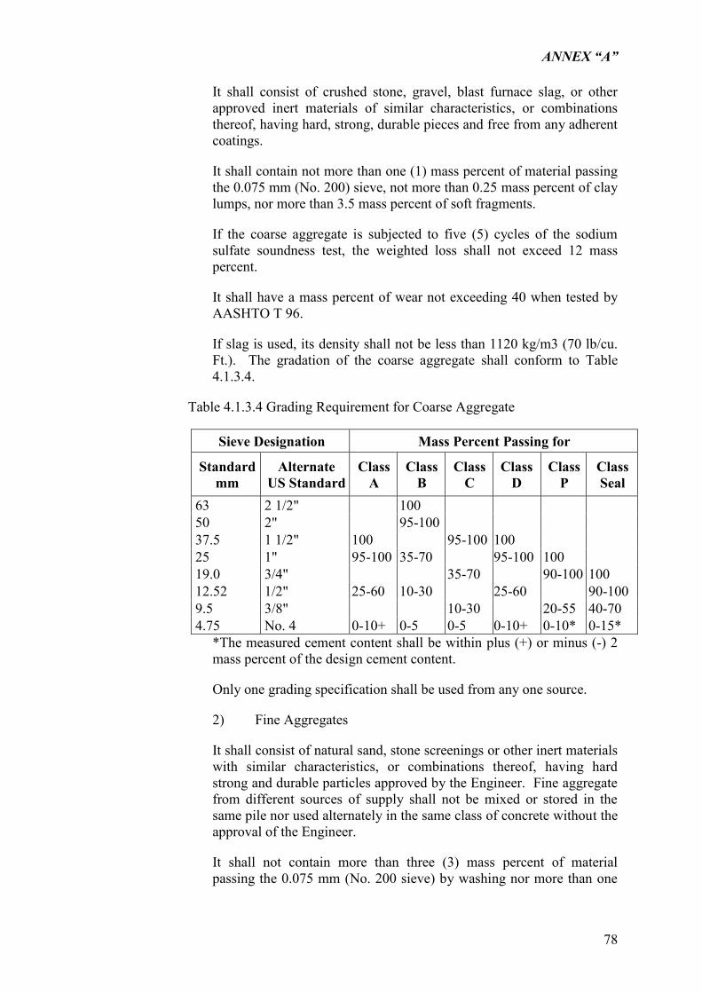
ANNEX “A”
78
It shall consist of crushed stone, gravel, blast furnace slag, or other approved inert materials of similar characteristics, or combinations thereof, having hard, strong, durable pieces and free from any adherent coatings.
It shall contain not more than one (1) mass percent of material passing the 0.075 mm (No. 200) sieve, not more than 0.25 mass percent of clay lumps, nor more than 3.5 mass percent of soft fragments.
If the coarse aggregate is subjected to five (5) cycles of the sodium sulfate soundness test, the weighted loss shall not exceed 12 mass percent.
It shall have a mass percent of wear not exceeding 40 when tested by AASHTO T 96.
If slag is used, its density shall not be less than 1120 kg/m3 (70 lb/cu. Ft.). The gradation of the coarse aggregate shall conform to Table 4.1.3.4.
Table 4.1.3.4 Grading Requirement for Coarse Aggregate
Sieve Designation Mass Percent Passing for
Standard mm
Alternate US Standard
Class A
Class B
Class C
Class D
Class P
Class Seal
63 2 1/2" 100 50 2" 95-100 37.5 1 1/2" 100 95-100 100 25 1" 95-100 35-70 95-100 100 19.0 3/4" 35-70 90-100 100 12.52 1/2" 25-60 10-30 25-60 90-100 9.5 3/8" 10-30 20-55 40-70 4.75 No. 4 0-10+ 0-5 0-5 0-10+ 0-10* 0-15*
*The measured cement content shall be within plus (+) or minus (-) 2 mass percent of the design cement content.
Only one grading specification shall be used from any one source.
2) Fine Aggregates
It shall consist of natural sand, stone screenings or other inert materials with similar characteristics, or combinations thereof, having hard strong and durable particles approved by the Engineer. Fine aggregate from different sources of supply shall not be mixed or stored in the same pile nor used alternately in the same class of concrete without the approval of the Engineer.
It shall not contain more than three (3) mass percent of material passing the 0.075 mm (No. 200 sieve) by washing nor more than one
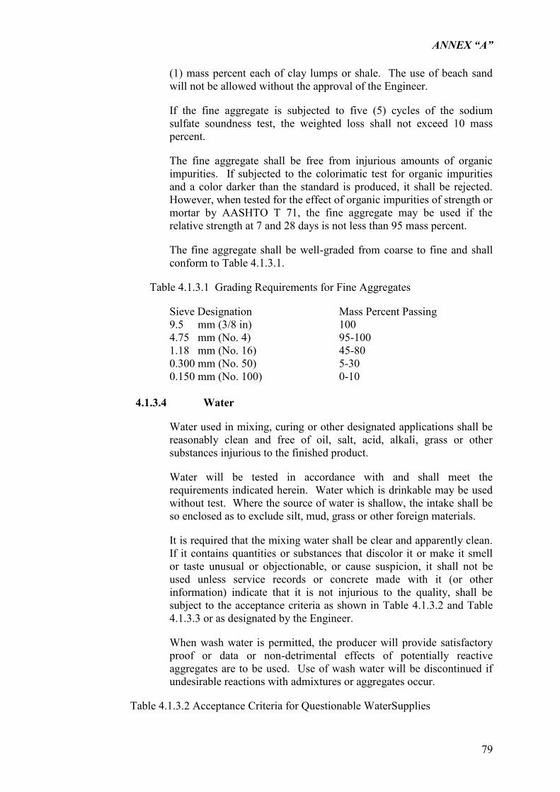
ANNEX “A”
79
(1) mass percent each of clay lumps or shale. The use of beach sand will not be allowed without the approval of the Engineer.
If the fine aggregate is subjected to five (5) cycles of the sodium sulfate soundness test, the weighted loss shall not exceed 10 mass percent.
The fine aggregate shall be free from injurious amounts of organic impurities. If subjected to the colorimatic test for organic impurities and a color darker than the standard is produced, it shall be rejected. However, when tested for the effect of organic impurities of strength or mortar by AASHTO T 71, the fine aggregate may be used if the relative strength at 7 and 28 days is not less than 95 mass percent.
The fine aggregate shall be well-graded from coarse to fine and shall conform to Table 4.1.3.1.
Table 4.1.3.1 Grading Requirements for Fine Aggregates
Sieve Designation Mass Percent Passing 9.5 mm (3/8 in) 100 4.75 mm (No. 4) 95-100 1.18 mm (No. 16) 45-80 0.300 mm (No. 50) 5-30 0.150 mm (No. 100) 0-10
4.1.3.4 Water
Water used in mixing, curing or other designated applications shall be reasonably clean and free of oil, salt, acid, alkali, grass or other substances injurious to the finished product.
Water will be tested in accordance with and shall meet the requirements indicated herein. Water which is drinkable may be used without test. Where the source of water is shallow, the intake shall be so enclosed as to exclude silt, mud, grass or other foreign materials.
It is required that the mixing water shall be clear and apparently clean. If it contains quantities or substances that discolor it or make it smell or taste unusual or objectionable, or cause suspicion, it shall not be used unless service records or concrete made with it (or other information) indicate that it is not injurious to the quality, shall be subject to the acceptance criteria as shown in Table 4.1.3.2 and Table 4.1.3.3 or as designated by the Engineer.
When wash water is permitted, the producer will provide satisfactory proof or data or non-detrimental effects of potentially reactive aggregates are to be used. Use of wash water will be discontinued if undesirable reactions with admixtures or aggregates occur.
Table 4.1.3.2 Acceptance Criteria for Questionable WaterSupplies
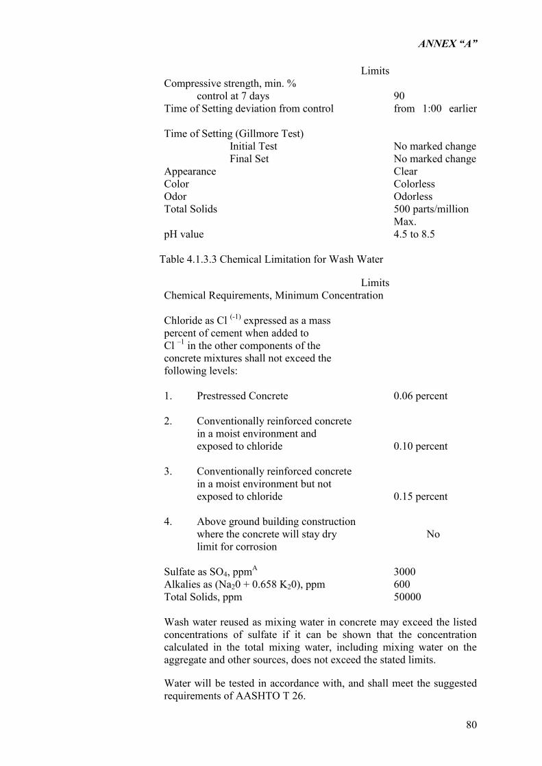
ANNEX “A”
80
Limits Compressive strength, min. %
control at 7 days 90 Time of Setting deviation from control from 1:00 earlier
Time of Setting (Gillmore Test)
Initial Test No marked change Final Set No marked change
Appearance Clear Color Colorless Odor Odorless Total Solids 500 parts/million
Max. pH value 4.5 to 8.5
Table 4.1.3.3 Chemical Limitation for Wash Water
Limits Chemical Requirements, Minimum Concentration
Chloride as Cl (-1) expressed as a mass percent of cement when added to Cl –1 in the other components of the concrete mixtures shall not exceed the following levels: 1. Prestressed Concrete 0.06 percent 2. Conventionally reinforced concrete in a moist environment and exposed to chloride 0.10 percent 3. Conventionally reinforced concrete in a moist environment but not exposed to chloride 0.15 percent 4. Above ground building construction where the concrete will stay dry No limit for corrosion
Sulfate as SO4, ppmA 3000 Alkalies as (Na20 + 0.658 K20), ppm 600 Total Solids, ppm 50000
Wash water reused as mixing water in concrete may exceed the listed concentrations of sulfate if it can be shown that the concentration calculated in the total mixing water, including mixing water on the aggregate and other sources, does not exceed the stated limits.
Water will be tested in accordance with, and shall meet the suggested requirements of AASHTO T 26.
ANNEX “A”
81
Water known to be of potable quality may be used without test.
4.1.3.5 Curing Materials
1) Impervious sheet materials shall conform to ASTM C 171, or equivalent except that polyethylene film, if used, shall be white opaque.
2) Burlap shall be commercial quality, non-staining type consisting 2 layers minimum.
3) Membrane Forming Curing Compound shall conform to ASTM C 309, AASHTO M 148 or equivalent.
4.1.3.6
Form materials, coatings and ties are specified in paragraph 4.1.6, FORMWORKS AND FALSE WORKS.
4.1.3.7
Reinforcement
1) Deformed bars conforming to DSB 275, Bars for reinforcing concrete of PS 681-04.02 :1975 First Revision, or equivalent.
2) Mesh reinforcement conforming to AASHTO M 55.
4.1.3.8
Expansion Joint Filler
Poured filler for joints shall conform to the requirements of AASHTO M 173.
Preformed joint filler shall conform to the requirements of AASHTO M 33 (ASTM D 994), AASHTO M 153 to M 213, AASHTO M 220 or ASTM D 751, type and class suitable for the use intended and shall be punched to admit the dowels where called for on the Drawings.
The filler for its joint shall be furnished in a single piece for the depth and width required for the joint unless otherwise authorized by the Engineer. When the use of more than one piece is authorized for a joint, the abutting ends shall be fastened securely, and held accurately to shape, by stapling or other positive fastening satisfactory to the Engineer.
4.1.3.9
Vapor Barrier and Sealant
1) Asphalt-saturated waterproof reinforced draft paper.
ANNEX “A”
82
2) Polyethylene sheeting shall be not less than 0.2 mm nominal thickness.
4.1.4 SAMPLES AND TESTING
4.1.4.1
Testing except as otherwise specified herein shall be performed by an approved testing agency as proposed by the Contractor and approved by the Engineer at no additional cost to the Employer.
1) Cement
Sampled either at the mill or at the site of the work and tested by an approved independent commercial or national testing laboratory at no additional cost to the Employer. Certified copies of laboratory test reports shall be furnished for each lot of cement and shall include all test data, results, land certificates that the sampling and testing procedures are in conformity with the Specifications. No cement shall be used until notice has been given by the Engineer that the test results are satisfactory. Cement that has been stored, other than in bins at the mills, for more than 4 months after delivery to the Site shall be retreated before use. Cement delivered at the Site and later found under test to be unsuitable shall not be incorporated into the permanent works.
2) Aggregates
Tested as prescribed in ASTM C 33.
3) Reinforcement
Certified copies of mill certificates of tests shall accompany deliveries of steel bar reinforcement. If requested by the Engineer, additional testing of the materials shall be made at the Contractor‟s expense.
4) Concrete Tests
For test purposes, three sets of test specimens shall be taken, under the instruction of the Engineer, from each 50 cubic meter or fraction thereof of each class of concrete placed. At least one set of test specimen shall be provided for each class of concrete placed in each 8-hour shift.
Each shall consist of two test specimens, and shall be made from a separate batch. Samples shall be secured in conformity with ASTM C 172. Test specimens shall be made, cured, and packed for shipment in accordance with ASTM C 31. Cylinders will be tested in accordance with ASTM C 39 by and at the expense of the contractor. Test specimens will be evaluated separately by the Engineer for meeting strength requirements with CONCRETE QUALITY of ACI 318. The standard age of test shall be 28 days, but 7-day test may be used, with
ANNEX “A”
83
the permission of the Engineer, provided that the relation between the 7-day and 28-day strengths on the concrete is established by tests for the materials and proportions used. When samples fail to conform to the requirements for strength, the Engineer shall have the right to order a change in the proportions of the concrete mix for the remaining portions of the work at no additional cost to the Engineer.
5) Test of hardened concrete in or removed from the Structure:
When the result of the strength test of the control specimens indicates the concrete as placed does not meet the requirements or where there is other evidence that the quality of the concrete is below the requirements, test on core of in-place concrete shall be made in conformity with ASTM C 42.
Core specimens shall be obtained by the Contractor and shall be tested. Any deficiency shall be corrected. If the Contractor elects a load test, he may submit a proposal for approval. If the proposal is approved, the load test shall be made by the Contractor and the test results evaluated by the Engineer in conformity with Chapter 20 of ACI 318. The cost of the load test shall be borne by the contractor. If any concrete shows evidence of failure during the load test or fails the load test, the deficiency shall be corrected in a manner approved by the Engineer at no additional cost to the Employer.
6) Admixtures
All admixtures shall be tested and those that have been in storage at the Project Site for longer than 6 months shall be retest and if found to be satisfactory, it can be used.
a) Air-Entraining Admixtures
Tested for conformity to the referenced specification under which it is furnished. The testing shall be conducted with cement and aggregate proposed for the Project.
b) Other admixtures, if approved, tested for conformity to the referenced specifications under which it is furnished. The testing shall be conducted with cement and aggregates proposed for the Project.
4.1.5 STORAGE
4.1.5.1
Storage accommodations for concrete materials shall be subject to approval and shall afford easy access for inspection and identification of each shipment in accordance with test reports.
1) Cement
ANNEX “A”
84
Immediately upon receipt at the Site, the cement shall be stored separately in a dry weather tight, properly ventilated structure, with adequate provisions for prevention or absorption of moisture. Cement bags should not be stacked more than 13 bags high. The cement most likely to have been exposed to moisture or stored in bags for more than 4 months shall not be used unless proven by tests to be in good condition.
2) Aggregates
Stored to assure good drainage, to preclude inclusion of foreign matter, and to preserve the gradation.
3) Reinforcement
All reinforcements shall be stored separately for each grade and diameter, off the ground in a shed or under a suitable rain-proof cover.
4.1.6 FORMWORKS AND FALSEWORKS
4.1.6.1 Falsework Design And Drawings
Detailed working drawings and supporting calculations of the falsework shall be furnished by the Contractor to the Engineer. No falsework construction shall start until the Engineer has reviewed and approved the design. The Contractor shall provide sufficient time for the Engineer to complete this review. Such time shall be proportionate to the complexity of the falsework design and in no case be less than two weeks.
The Contractor may review the falsework drawings at any time provided sufficient time is allowed for the Engineer‟s review before construction is started on the revised portion.
Assumptions used in design of the falsework shall include but not be limited to the following:
1. The entire superstructure cross-section, except for the railing, shall be considered to be placed at one time, except when in the opinion of the Engineer, a portion of the load is carried by members previously cast and having attained a specified strength.
2. The loading used on timber piles shall not exceed the bearing value for the pile and shall in no case exceed 20 tons per pile.
3. Soil bearing values and soil condition (wet and dry) shall be designated by the Contractor on the falsework drawings. Falsework footings shall be designed to carry the loads imposed upon them without exceeding estimated soil bearing values or allowable settlements.
ANNEX “A”
85
4. The maximum loadings and deflections used on jacks, brackets, columns and other manufactured devices shall not exceed the manufacturer‟s recommendations. If requested by the Engineer, the Contractor shall furnish catalogue or other data verifying these recommendations.
5. If the concrete is to be pre-stressed, the falsework shall be designed to support any increased or readjusted loads caused by the pre-stressing forces.
6. Joints supporting slabs and overhangs shall be considered as falsework and designed as such.
Anticipated total settlements of falsework and forms shall be indicated by the Contractor on the falsework drawings. These should include falsework footing settlements over 20 mm will not be allowed unless otherwise permitted by the Engineer. Deck slab forms between girders shall be constructed with no allowance for settlement relative to the girders.
Detailed calculations by the Contractor showing the stresses deflections, and camber necessary to compensate for said deflections in all load supporting members shall be supplied.
4.1.6.2 Falsework Construction
The falsework shall be constructed to conform to the falsework drawings. The materials used in the falsework construction shall be of the quantity and quality necessary to withstand the stresses imposed. The workmanship used in falsework shall be of such quality that the falsework will support the loads imposed on it without excessive settlement or take-up beyond that shown on the falsework drawings.
When falsework is supported on piles, the piles shall be driven in a bearing value equal to the total calculated pile loading as shown on the falsework drawings.
Suitable jacks or edges shall be used in connection with falsework to set the forms to their required grade and to take up any excessive settlement in the falsework either before or during the placing of concrete.
4.1.6.3 Removing Falsework
Unless otherwise shown on the drawings, or permitted by the Engineer, falsework supporting any span of a supported bridge shall not be released.
Falsework supporting deck overhangs and deck slabs between girders shall not be released until 7 days after the deck concrete has been placed.
ANNEX “A”
86
In addition to the above requirements, falsework for place pre-stressed portion of structure shall not be released until after the pre-stressing steel has been tensioned.
All falsework materials shall be completely removed. Falsework piling shall be removed at least 50 cm below the surface of the original ground or stream bed. When falsework piling is driven within the limits of ditch or channel excavation areas, the falsework piling within such areas shall be removed to at least 50 cm below the bottom and side slopes of said excavated area.
All debris and refuse resulting from work shall be removed and the site left in a neat and presentable condition.
4.1.6.4
Formwork Design and Drawings
The Contractor shall prepare drawings and material data for the formwork and shutters to be submitted to the Engineer for approval unless otherwise directed.
The requirements for design of formwork are the same as described under Section 4.1.6.1.
4.1.6.5
Formwork Construction
Concrete forms shall be mortar-tight, true to the dimensions, lines and grades of the structure and with the sufficient strength, rigidity, shape and surface smoothness as to leave the finished works true to the dimensions shown on the Drawings or required by the Engineer and with the surface finish as specified.
Formwork and shutters are to be constructed in accordance with the approved Drawings.
The inside surfaces of forms shall be cleaned of all dirt, mortar and foreign material. Forms which will later be removed shall be thoroughly coated with form oil prior to use. The form oil shall be of commercial quality form oil or other approved coating which will permit the ready release of the forms and will not discolor the concrete.
Concrete shall not be deposited in the forms until all work in connection with constructing the forms has been completed, all materials required to be embedded in the concrete have been placed before the unit is to be poured, and the Engineer has inspected and approved said forms and materials. Such work shall include the removal of all dirt, chips, sawdust and other foreign material from the forms.
ANNEX “A”
87
The rate of depositing concrete in forms shall be such to prevent bulging of the forms or form panels in excess of the deflections permitted by the Specification.
Forms for all concrete surfaces which will not be completely enclosed or hidden below the permanent ground surface shall conform to the requirements herein for forms for exposed surfaces. Interior surfaces of underground drainage structures shall be considered to be completely enclosed surfaces.
Formwork for concrete place under water shall be watertight. When lumber is used, this shall be planed, tongued and grooved.
Forms for exposed concrete surfaces shall be designed and constructed so that the formed surface of the concrete does not undulate excessively in any direction between studs, joists, form stiffeners, form fasteners, or wales. Undulations exceeding either 2 mm or 1/270 of the center to center distance between studs, joists, form stiffeners, form fasteners, or wales will be considered to be excessive. Should any form of forming system, even though previously approved for use, produce a concrete surface with excessive undulations, its use shall be discontinued until modifications satisfactory to the Engineer have been made. Portions of concrete structures with surface undulations in excess of the limits herein specified may be rejected by the Engineer.
All exposed surfaces of similar portions of a concrete structure shall be formed with the same forming material or with materials which produce similar concrete surface textures, color and appearance.
Forms for exposed surfaces shall be made of form materials of even thickness and width and with uniform texture. The materials shall have sharp edges and be mortar-tight.
Forms for exposed surfaces shall be constructed with triangular fillets at least 20 mm wide attached so as to prevent Mortar runs and to produce smooth straight chamfers at all sharp edges of the concrete.
Form fasteners consisting of form bolts, clamps or other devices shall be used as necessary to prevent spreading of the forms during concrete placement. The use of ties consisting of twisted wire loops to hold forms in position will not be permitted.
Anchor devices may be cast into the concrete for later use in supporting forms or for lifting pre-cast members.
The use of driven types of anchorage for fastening forms of form supports to concrete will not be permitted.
4.1.6.6 Removal of Forms and Falsework
Forms and falsework shall not be removed without the consent of the Engineer. The Engineer‟s consent shall not relieve the Contractor of
ANNEX “A”
88
responsibility for the safety of the work. Blocks and bracing shall be removed at the time the forms are removed and in no case shall any portion of the wood forms be left in the concrete.
Supporting forms of shoring shall not be removed until structural members have acquired sufficient strength to support safely their own weight and any construction and/or storage load to which they may be subjected, but in no case shall they be removed in less than 7 days, nor shall forms used for curing be removed before expiration of curing period except as specified in paragraph CURING. Care shall be taken to avoid spalling the concrete surface or damaging concrete edges. Wood forms shall be completely removed.
a) Control Tests
Results of suitable control tests will be used as evidence that concrete has attained sufficient strength to permit removal of supporting forms. Cylinders required for control tests shall be provided in addition to those otherwise required by the Specifications. Test specimens shall be removed from molds at the end of 24 hours and stored near to the structure as practicable the same protection from the elements during curing. Supporting forms or shoring shall not be removed until control-test specimens have attained strength of at least 15.68 MPa. The newly unsupported portions of the structure shall not be subject to heavy construction or materials loading.
b) Tie-rods to be entirely removed from the wall shall be loosened 24 hours after concrete is placed, and form ties, except for a sufficient number to hold forms in place, may be removed at that time. Ties wholly withdrawn from wall shall be pulled toward the face that will be concealed from view in the permanent work.
Filling of tie-rods or bolt holes as specified herein or approved by the Engineer.c)
Falsework removal for continuous or cantilevered structures shall be as directed by the Engineer or shall be such that the structure is gradually subjected to its working stress.
When concrete strength tests are used for removal of forms and supports, such removal should not begin until the concrete has attained the percentage of the specified design strength shown in the table below.
Minimum Time Minimum %age Design Strength Centering under Girders, beams Frames or arches 14 days 80% Floor slabs 14 days 70% Walls 1 day 70% Columns 2 days 70%
ANNEX “A”
89
Sides of beams and all other vertical surfaces 1 day 70%
In continuous structures, falsework shall not be released in any span until the first and second adjoining spans on each side have reached the strength specified or as approved by the Engineer.
In order to determine the condition of column concrete, forms shall be removed from columns before releasing supports from beneath beams and girders.
Forms and falsework shall not be released from under concrete without first determining if the concrete has gained adequate strength without regard to the time element. In the absence of strength determination, the forms and falsework are to remain in place until removal is permitted by the Engineer.
The forms for footings constructed within cofferdams or cribs may be left in place when, in the opinion of the Engineer, their removal would endanger the safety of the cofferdam or crib, and when the forms so left intact will not be exposed to view in the finished structure. All other forms shall be removed whether above or below the ground line or water level.
4.1.6.7 Concrete Surfaces To Be Smooth
Form surfaces that will be in contact with concrete shall be of materials that is non-reactive with concrete and that will produce concrete surfaces equivalent in smoothness and appearance to that produced by new 1.2 x 2.4 meters plywood panels. Smaller size panels shall be used only where required on joints, with each area less than 1.2 meters wide formed with single panel accurately cut to the required dimensions. Cut surfaces shall be smooth and treated with form coating. Panel joints that will be in contact with concrete with defects that will impair the texture and appearance of finish surfaces shall not be used. Form lining, if used, shall be installed over solid backing. Column forms shall be made with a minimum number of joints.
4.1.6.8 Concrete Surfaces To Be Exposed
Form surfaces that will be in contact with concrete shall be sound, tight lumber or other material producing equivalent finish.
4.1.6.9Form Ties
Form ties shall be factory-fabricated, removal or snap-off metal ties of design that it will not allow form deflection and will not spill concrete upon removal. Solid backing shall be provided for each tie. Ties shall be fitted with devices that will leave holes in the concrete surface not less than 9 mm nor more than 25 mm in diameter and of depth not less than 25 mm.
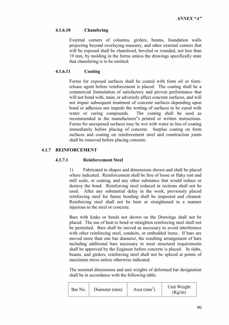
ANNEX “A”
90
4.1.6.10 Chamfering
External corners of columns, girders, beams, foundation walls projecting beyond overlaying masonry, and other external corners that will be exposed shall be chamfered, beveled or rounded, not less than 19 mm, by molding in the forms unless the drawings specifically state that chamfering is to be omitted.
4.1.6.11 Coating
Forms for exposed surfaces shall be coated with form oil or form-release agent before reinforcement is placed. The coating shall be a commercial formulation of satisfactory and proven performance that will not bond with, stain, or adversely affect concrete surfaces, and will not impair subsequent treatment of concrete surfaces depending upon bond or adhesion nor impede the wetting of surfaces to be cured with water or curing compounds. The coating shall be used as recommended in the manufacturer‟s printed or written instructions. Forms for unexposed surfaces may be wet with water in lieu of coating immediately before placing of concrete. Surplus coating on form surfaces and coating on reinforcement steel and construction joints shall be removed before placing concrete.
4.1.7 REINFORCEMENT
4.1.7.1 Reinforcement Steel
1) Fabricated to shapes and dimensions shown and shall be placed where indicated. Reinforcement shall be free of loose or flaky rust and mill scale, or coating, and any other substance that would reduce or destroy the bond. Reinforcing steel reduced in sections shall not be used. After any substantial delay in the work, previously placed reinforcing steel for future bonding shall be inspected and cleaned. Reinforcing steel shall not be bent or straightened in a manner injurious to the steel or concrete.
Bars with kinks or bends not shown on the Drawings shall not be placed. The use of heat to bend or straighten reinforcing steel shall not be permitted. Bars shall be moved as necessary to avoid interference with other reinforcing steel, conduits, or embedded items. If bars are moved more than one bar diameter, the resulting arrangement of bars including additional bars necessary to meet structural requirements shall be approved by the Engineer before concrete is placed. In slabs, beams, and girders, reinforcing steel shall not be spliced at points of maximum stress unless otherwise indicated.
The nominal dimensions and unit weights of deformed bar designation shall be in accordance with the following table.
Bar No. Diameter (mm) Area (mm2) Unit Weight (Kg/m)
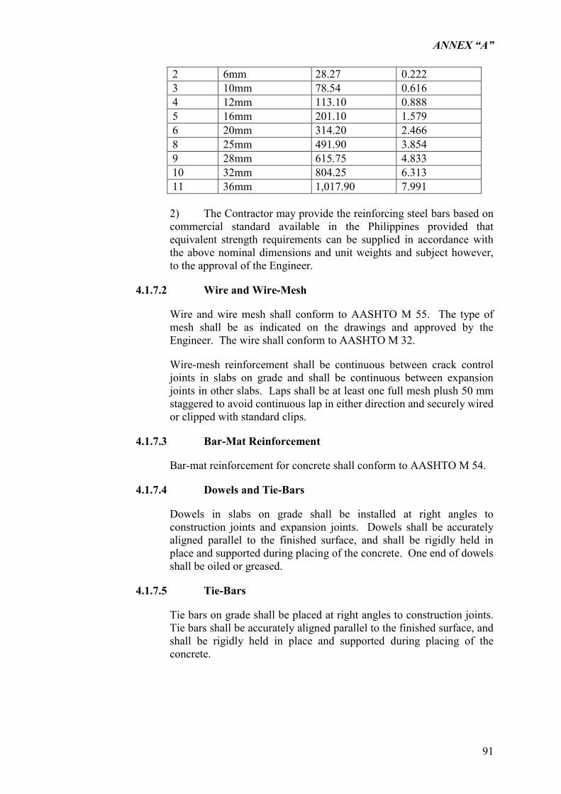
ANNEX “A”
91
2 6mm 28.27 0.222 3 10mm 78.54 0.616 4 12mm 113.10 0.888 5 16mm 201.10 1.579 6 20mm 314.20 2.466 8 25mm 491.90 3.854 9 28mm 615.75 4.833 10 32mm 804.25 6.313 11 36mm 1,017.90 7.991
2) The Contractor may provide the reinforcing steel bars based on commercial standard available in the Philippines provided that equivalent strength requirements can be supplied in accordance with the above nominal dimensions and unit weights and subject however, to the approval of the Engineer.
4.1.7.2 Wire and Wire-Mesh
Wire and wire mesh shall conform to AASHTO M 55. The type of mesh shall be as indicated on the drawings and approved by the Engineer. The wire shall conform to AASHTO M 32.
Wire-mesh reinforcement shall be continuous between crack control joints in slabs on grade and shall be continuous between expansion joints in other slabs. Laps shall be at least one full mesh plush 50 mm staggered to avoid continuous lap in either direction and securely wired or clipped with standard clips.
4.1.7.3 Bar-Mat Reinforcement
Bar-mat reinforcement for concrete shall conform to AASHTO M 54.
4.1.7.4 Dowels and Tie-Bars
Dowels in slabs on grade shall be installed at right angles to construction joints and expansion joints. Dowels shall be accurately aligned parallel to the finished surface, and shall be rigidly held in place and supported during placing of the concrete. One end of dowels shall be oiled or greased.
4.1.7.5 Tie-Bars
Tie bars on grade shall be placed at right angles to construction joints. Tie bars shall be accurately aligned parallel to the finished surface, and shall be rigidly held in place and supported during placing of the concrete.
ANNEX “A”
92
4.1.7.6 Supports
Supports shall be provided in conformity with ACI 315 and ACI 318 unless otherwise indicated or specified. Wire, ties, when used, shall be rigidly held in place and supported during placing of the concrete.
1) For Slabs on Grade
Reinforcement shall be supported on precast structure units spaced at intervals required by size of reinforcement used, to keep reinforcement the minimum height specified or indicated above the underside of slab or footing.
2) For Slabs other than on Grade
Supports for which any portion will be less than 25 mm concrete surface that will be exposed to view or painted shall be plastic-coated steel conforming to ACI 315, stainless steel, pre-cast concrete units, or plastic. Pre-cast concrete units shall be wedge-shaped, not larger than 90 mm by 90 mm, and of thickness equal to that indicated for concrete protection of reinforcement. The pre-cast units shall have cast-in galvanized tie wires hooked at top for anchorage and shall blend with concrete surfaces after finishing is completed. Concrete shall be of the same quality as for slabs, but with coarse aggregate reduced. Plastic supports shall be of strength and spaced so as not to deform weight to which it is subjected.
4.1.7.7 Welding Reinforcing Bars
Welding of reinforcing bars shall only be permitted where shown. All welding shown shall be performed in accordance with AWS D 12.1 or equivalent.
4.1.7.8 Exposed Reinforcement Bars, Dowels, Etc.
Exposed reinforcement bars, dowels and plates intended for bonding with future extensions shall be protected from corrosion.
4.1.7.9 Concrete Protection For Reinforcement
1) The minimum cover of reinforcement shall be as indicated on the Drawings or as specified in the other Sections and as shown in the table below.
2) Tolerance for concrete cover of reinforcing steel other than tendons:
MINIMUM COVER MAXIMUM VARIATION 75 mm or more 9 mm less than 75 mm 6 mm
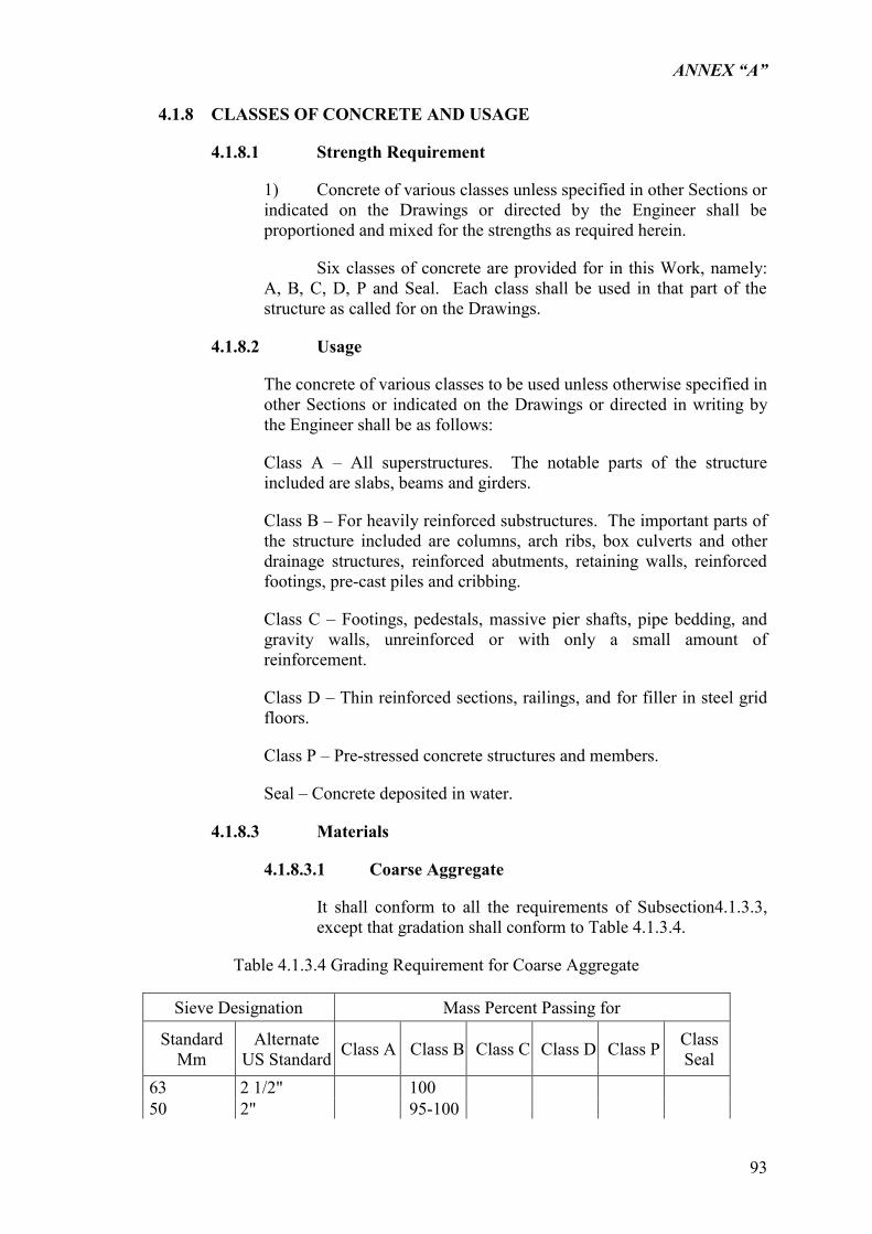
ANNEX “A”
93
4.1.8 CLASSES OF CONCRETE AND USAGE
4.1.8.1 Strength Requirement
1) Concrete of various classes unless specified in other Sections or indicated on the Drawings or directed by the Engineer shall be proportioned and mixed for the strengths as required herein.
Six classes of concrete are provided for in this Work, namely: A, B, C, D, P and Seal. Each class shall be used in that part of the structure as called for on the Drawings.
4.1.8.2 Usage
The concrete of various classes to be used unless otherwise specified in other Sections or indicated on the Drawings or directed in writing by the Engineer shall be as follows:
Class A – All superstructures. The notable parts of the structure included are slabs, beams and girders.
Class B – For heavily reinforced substructures. The important parts of the structure included are columns, arch ribs, box culverts and other drainage structures, reinforced abutments, retaining walls, reinforced footings, pre-cast piles and cribbing.
Class C – Footings, pedestals, massive pier shafts, pipe bedding, and gravity walls, unreinforced or with only a small amount of reinforcement.
Class D – Thin reinforced sections, railings, and for filler in steel grid floors.
Class P – Pre-stressed concrete structures and members.
Seal – Concrete deposited in water.
4.1.8.3 Materials
4.1.8.3.1 Coarse Aggregate
It shall conform to all the requirements of Subsection4.1.3.3, except that gradation shall conform to Table 4.1.3.4.
Table 4.1.3.4 Grading Requirement for Coarse Aggregate
Sieve Designation Mass Percent Passing for
Standard Mm
Alternate US Standard Class A Class B Class C Class D Class P Class
Seal 63 2 1/2" 100 50 2" 95-100
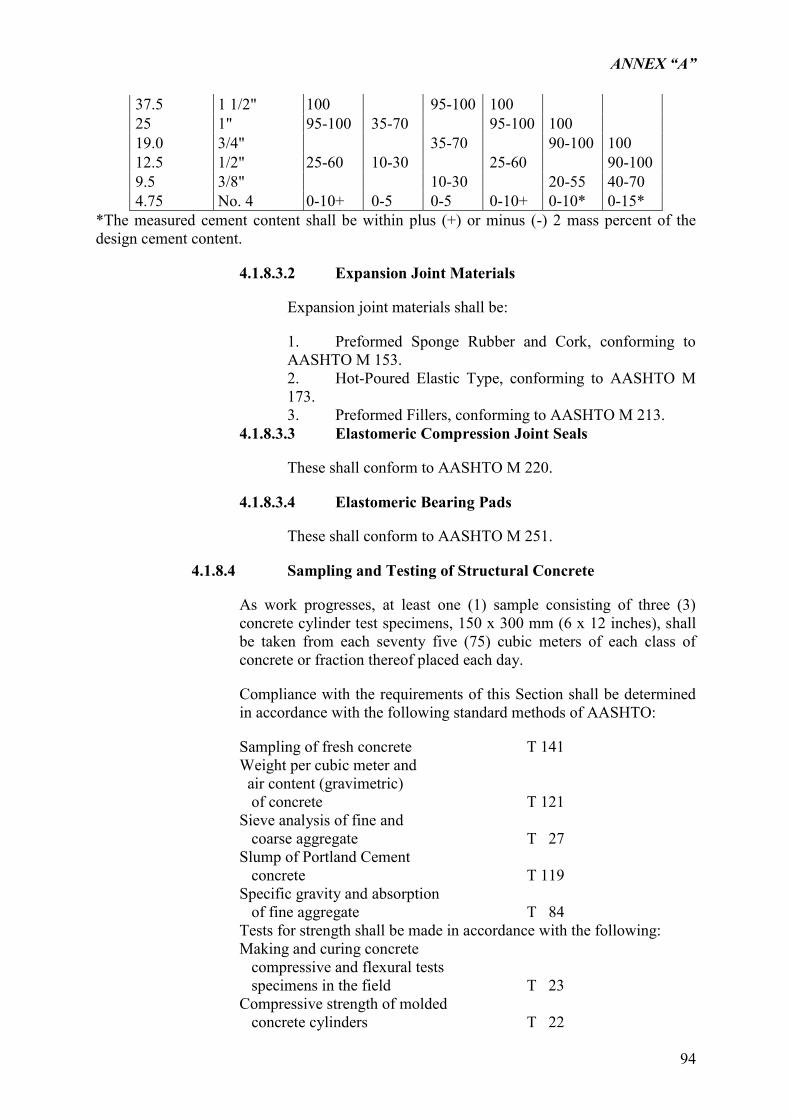
ANNEX “A”
94
37.5 1 1/2" 100 95-100 100 25 1" 95-100 35-70 95-100 100 19.0 3/4" 35-70 90-100 100 12.5 1/2" 25-60 10-30 25-60 90-100 9.5 3/8" 10-30 20-55 40-70 4.75 No. 4 0-10+ 0-5 0-5 0-10+ 0-10* 0-15*
*The measured cement content shall be within plus (+) or minus (-) 2 mass percent of the design cement content.
4.1.8.3.2 Expansion Joint Materials
Expansion joint materials shall be:
1. Preformed Sponge Rubber and Cork, conforming to AASHTO M 153. 2. Hot-Poured Elastic Type, conforming to AASHTO M 173. 3. Preformed Fillers, conforming to AASHTO M 213.
4.1.8.3.3 Elastomeric Compression Joint Seals
These shall conform to AASHTO M 220.
4.1.8.3.4 Elastomeric Bearing Pads
These shall conform to AASHTO M 251.
4.1.8.4 Sampling and Testing of Structural Concrete
As work progresses, at least one (1) sample consisting of three (3) concrete cylinder test specimens, 150 x 300 mm (6 x 12 inches), shall be taken from each seventy five (75) cubic meters of each class of concrete or fraction thereof placed each day.
Compliance with the requirements of this Section shall be determined in accordance with the following standard methods of AASHTO:
Sampling of fresh concrete T 141 Weight per cubic meter and air content (gravimetric) of concrete T 121 Sieve analysis of fine and coarse aggregate T 27 Slump of Portland Cement concrete T 119 Specific gravity and absorption of fine aggregate T 84
Tests for strength shall be made in accordance with the following: Making and curing concrete compressive and flexural tests specimens in the field T 23 Compressive strength of molded concrete cylinders T 22
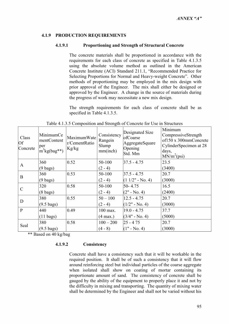
ANNEX “A”
95
4.1.9 PRODUCTION REQUIREMENTS
4.1.9.1 Proportioning and Strength of Structural Concrete
The concrete materials shall be proportioned in accordance with the requirements for each class of concrete as specified in Table 4.1.3.5 using the absolute volume method as outlined in the American Concrete Institute (ACI) Standard 211.1, “Recommended Practice for Selecting Proportions for Normal and Heavy-weight Concrete”. Other methods of proportioning may be employed in the mix design with prior approval of the Engineer. The mix shall either be designed or approved by the Engineer. A change in the source of materials during the progress of work may necessitate a new mix design.
The strength requirements for each class of concrete shall be as specified in Table 4.1.3.5.
Table 4.1.3.5 Composition and Strength of Concrete for Use in Structures
Class Of Concrete
MinimumCementContent per m3kg(bag**)
MaximumWater/CementRatio Kg/kg
ConsistencyRangein Slump mm(inch)
Designated Size ofCoarse AggregateSquare Opening Std. Mm
Minimum CompressiveStrength of150 x 300mmConcrete CylinderSpecimen at 28 days, MN/m2(psi)
A 360 0.52 50-100 37.5 - 4.75 23.5 (9 bags) (2 - 4) (3400)
B 360 0.53 50-100 37.5 - 4.75 20.7 (9 bags) (2 - 4) (1 1/2" - No. 4) (3000)
C 320 0.58 50-100 50- 4.75 16.5 (8 bags) (2 - 4) (2" - No. 4) (2400)
D 380 0.55 50 – 100 12.5 - 4.75 20.7 (9.5 bags) (2 - 4) (1/2" - No. 4) (3000)
P 440 0.49 100 max. 19.0 - 4.75 37.7 (11 bags) (4 max.) (3/4" - No. 4) (5000)
Seal 380 0.58 100 – 200 25 - 4 75 20.7 (9.5 bags) (4 - 8) (1" - No. 4) (3000)
** Based on 40 kg/bag
4.1.9.2 Consistency
Concrete shall have a consistency such that it will be workable in the required position. It shall be of such a consistency that it will flow around reinforcing steel but individual particles of the coarse aggregate when isolated shall show on coating of mortar containing its proportionate amount of sand. The consistency of concrete shall be gauged by the ability of the equipment to properly place it and not by the difficulty in mixing and transporting. The quantity of mixing water shall be determined by the Engineer and shall not be varied without his
ANNEX “A”
96
consent. Concrete as dry as it is practical to place with the equipment specified shall be used.
4.1.9.3 Batching
Measuring and batching of materials shall be done at a batching plant.
1. Portland Cement
Either sacked or bulk cement may be used. No fraction of a sack of cement shall be used in a batch of concrete unless the cement is weighed.
All bulk cement shall be weighed on an approved weighing device. The bulk cement weighing hopper shall be properly sealed and vented to preclude dusting operation. The discharge chute shall not be suspended from the weighing hopper and shall be so arranged that cement will neither be lodged in it nor leak from it.
Accuracy of batching shall be within plus (+) or minus (-) 1 mass percent.
2. Water
Water may be measured either by volume or by weight. The accuracy of measuring the water shall be within a range of error of not more than 1 percent.
3. Aggregates
Stockpiling of aggregates shall be in accordance with Subsection 4.1.9.5. All aggregates whether produced or handled by hydraulic methods or washed, shall be stockpiled or binned for draining at least 12 hours prior to batching. Rail shipment requiring more than 12 hours will be accepted as adequate binning only if the car bodies permit free drainage. If the aggregates contain high or non-uniform moisture content, storage or stockpile period in excess of 12 hours may be required by the Engineer.
Batching shall be so conducted as to result in a 2 mass percent maximum tolerance for the required materials.
4. Bins and Scales
The batching plant shall include separate bins for bulk cement, fine aggregate and for each size of coarse aggregate, a weighing hopper, and scales capable of determining accurately the mass of each component of the batch.
Scales shall be accurate to one half (0.5) percent throughout the range used.
5. Batching
ANNEX “A”
97
When batches are hauled to the mixer, bulk cement shall be transported either in waterproof compartments or between the fine and coarse aggregates. When cement is placed in contact with moist aggregates, batches will be rejected unless mixed within 1 ½ hours of such contact. Sacked cement may be transported on top of the aggregates.
Batches shall be delivered to the mixer separate and intact. Each batch shall be dumped cleanly into the mixer without loss, and, when more than one batch is carried on the truck, without spilling of material from one batch compartment into another.
6. Admixtures
The Contractor shall follow an approved procedure for adding the specified amount of admixture to each batch and will be responsible for its uniform operation during the progress of the work. He shall provide separate scales for the admixtures which are to be proportioned by weight, and accurate measures for those to be proportioned by volume. Admixtures shall be measured into the mixer with an accuracy of plus or minus (3) percent.
The use of calcium chloride as an admixture will not be permitted.
4.1.9.4 Mixing and Delivery
Concrete may be mixed at the site of construction, at a central point or by a combination of central point and truck mixing or by a combination of central point mixing and truck agitating. Mixing and delivery of concrete shall be in accordance with the appropriate requirements of AASHTO M 157 except as modified in the following paragraphs of this section, for truck mixing or a combination of central point and truck mixing or truck agitating. Delivery of concrete shall be regulated so that placing is at a continuous rate unless delayed by the placing operations. The intervals between delivery of batches shall not be so great as to allow the concrete in place to harden partially, and in no case shall such an interval exceed 30 minutes.
When volumetric measurements are authorized, the weight proportions shall be converted to equivalent volumetric proportions. In such cases, suitable allowance shall be made for variations in the moisture condition of the aggregates, including the bulking effect in the fine aggregate. Batching and mixing shall be in accordance with ASTM C 685, Section 6 through 9.
For batch mixing in the site of construction or at a central point, a batch mixer, or an approved type shall be used. Mixer having a rated capacity of less than one bag batch shall not be used. The volume of concrete mixed per batch shall not exceed the mixer‟s nominal capacity as shown on the manufacturer‟s standard rating plate on the mixer except that an overload up to ten percent above the mixer‟s nominal capacity may be permitted, provided concrete test data from
ANNEX “A”
98
strength, segregation and uniform consistency are satisfactory and provided no spillage of concrete takes place. The batch shall be so charge into the drum that a portion of water shall enter in advance of the cement and aggregates. The flow of water shall be uniform and shall be in the drum by the end of the first 15 seconds of the mixing period. Mixing time shall be measured from the time all materials, except water, are in the drum. Mixing time shall not be less than 60 seconds for mixers having a capacity of 1.5 m3 or less. For mixers having a capacity greater than 1.5 m3, the mixing time shall not be less than 90 seconds. If timing starts, the instant the skip reaches its maximum raised position, 4 seconds shall be added to the specified mixing time. Mixing time ends when the discharge chute opens.
The mixer shall be operated at the drum speed as shown on the manufacturer‟s name plate on the mixer. Any concrete mixed less than the specified time shall be discarded and disposed off by the Contractor at his own expense.
The timing device on stationary mixers shall be equipped with a bell or other suitable warning device adjusted to give a clearly audible signal each time the lock is released. In case of failure of the timing device, the Contractor will be permitted to continue operations while it is being repaired, provided he furnished an approved timepiece equipped with minute and second hands. If the timing device is not placed in good working order within 24 hours, further use of the mixer will be prohibited until repairs are made.
Re-tempering concrete will not be permitted. Admixtures for increasing the workability, for retarding the set, or for accelerating the set or improving the pumping characteristics of the concrete will be permitted only when specifically provided for in the Contract, or authorized in writing by the Engineer.
1. Mixing Concrete: General
Concrete shall be thoroughly mixed in a mixer of an approved size and type that will insure a uniform distribution of the materials throughout the mass.
All concrete shall be mixed in mechanically operated mixers. Mixing plat and equipment for transporting and placing concrete shall be arranged with an ample auxiliary installation to provide a minimum supply of concrete in case of breakdown of machinery or in case the normal supply of concrete is disrupted. The auxiliary supply of concrete shall be sufficient to complete the casting of a section up to a construction joint that will meet the approval of the Engineer.
Equipment having components made of aluminum or magnesium alloys, which would have contact with plastic concrete during mixing, transporting or pumping of Portland Cement concrete, shall not be used.
ANNEX “A”
99
Materials shall be measured by weighing. The apparatus provided for weighing the aggregates and cement shall be suitably designed and constructed for this purpose. The accuracy of all weighing devices except that for water shall be such that successive quantities can be measured to within one percent of the desired amounts. The water measuring device shall be accurate to plus or minus 0.5 mass percent. All measuring devices shall be subject to the approval of the Engineer. Scales and measuring devices shall be tested at the expense of the Contractor as frequently as the Engineer may deem necessary to insure their accuracy.
Weighing equipment shall be insulated against vibration or movement of other operating equipment in the plant. When the entire plant is running, the scale reading at cut-off shall not vary from the weight designated by the Engineer more than one mass percent for cement, 1 ½ mass percent for any size of aggregate, or one more mass percent for the total aggregate in any batch.
2. Mixing Concrete at Site
Concrete mixers may be of the revolving drum or the revolving blade type and the mixing drum or blades shall be operated uniformly at the mixing speed recommended by the manufacturer. The pick-up and throw-over blades of mixers shall be restored or replaced when any part or section is worn 20 mm or more below the original height of the manufacturer‟s design. Mixers and agitators which have an accumulation of hard concrete or mortar shall not be used.
When bulk cement is used and volume of the batch is 0.5m3 or more, the scale and weigh hopper for Portland Cement shall be separate and distinct from the aggregate hopper or hoppers. The discharge mechanism of the bulk cement weigh hopper shall be interlocked against opening before the full amount of cement is in the hopper. The discharging mechanism shall also be interlocked against opening when the amount of cement in the hopper is underweight by more than 3 mass percent of the amount specified.
When the aggregate contains more water than the quantity necessary to produce a saturated surface-dry condition, representative samples shall be taken and the moisture content determined for each kind of aggregate.
The batch shall be so charged into the mixer that some water will enter in advance of cement and aggregate. All water shall be in the drum by the end of the first quarter of the specified mixing time.
Cement shall be batched and charged into the mixer so that it will not result in loss of cement due to the effect of wind, or in accumulation of cement on surfaces of conveyors or hoppers, or in other conditions which reduce or vary the required quantity of cement in the concrete mixture.
ANNEX “A”
100
The entire content of a batch mixer shall be removed from the drum before materials for a succeeding batch are placed therein. The materials composing a batch except water shall be deposited simultaneously into the mixer.
All concrete shall be mixed for a period of not less than 1 ½ minutes after all materials, including water, are in the mixer. During the period of mixing, the mixer shall operate at the speed for which it has been designed.
Mixers shall be operated with an automatic timing device that can be locked by the Engineer. The time device and discharge mechanics shall be so interlocked that during normal operation no part of the batch will be discharged until the specified mixing time has elapsed.
The first batch of concrete materials placed in the mixer shall contain a sufficient excess of cement, sand, and water to coat the inside of the drum without reducing the required mortar content of the mix. When mixing is to cease for a period of one hour or more, the mixer shall be thoroughly cleaned.
3. Mixing Concrete at Central Plant
Mixing at central plant shall conform to the requirements for mixing at the site.
4. Mixing Concrete in Truck
Truck mixers, unless otherwise authorized by the Engineer, shall be of the revolving drum type, watertight, and so constructed that the concrete can be mixed to insure a uniform distribution of materials throughout the mass. All solid materials for the concrete shall be accurately measured and charged into the drum at the proportioning plant. Except as subsequently provided, the truck mixer shall be equipped with a device by which the quantity of water added can be readily verified. The mixing water may be added directly to the batch, in which case a tank is not required. Truck mixers may be required to be provided with a means of which the mixing time can be readily verified by the Engineer.
The maximum size of batch in truck mixers shall not exceed the minimum rated capacity of the mixer as stated by the manufacturer and stamped in metal on the mixer. Truck mixing shall, unless otherwise directed be continued for not less than 100 revolutions after all ingredients, including water, are in the drum. The mixing speed shall not be less than 4 rpm, nor more than 6 rpm.
Mixing shall begin within 30 minutes after the cement has been added either to the water or aggregate, but when cement is charged into a mixer drum containing water or surface-wet aggregate and when the temperature is above 32 deg. C, this limit shall be reduced to 15 minutes. The limitation in time between the introduction of the
ANNEX “A”
101
cement to the aggregate and the beginning of the mixing may be waived when, in the judgment of the Engineer, the aggregate is sufficiently free from moisture so that there will be no harmful effects on the cement.
When a truck mixer is used for transportation, the mixing time specified in Subsection 4.1.9 at a stationary mixer may be reduced to 30 seconds and the mixing completed in a truck mixer. The mixing time in the truck mixer shall be as specified for truck mixing.
5. Transporting Mixed Concrete
Mixed concrete may only be transported to the delivery point in truck agitators or truck mixers operating at the speed designated by the manufacturers of the equipment as agitating speed, or in non-agitating hauling equipment, provided the consistency and workability of the mixed concrete upon discharge at the delivery point is suitable for adequate placement and consolidation in place.
Truck agitators shall be loaded not to exceed the manufacturer‟s guaranteed capacity. They shall maintain the mixed concrete in a thoroughly mixed and uniform mass during hauling.
No additional mixing water shall be incorporated into the concrete during hauling or after arrival at the delivery point.
The rate of discharge of mixed concrete from truck mixers or agitators shall be controlled by the speed of rotation of the drum in the discharge direction with the discharge gate fully open.
When a truck mixer or agitator is used for transporting concrete to the delivery point, discharge shall be completed within one hour, or before 250 revolutions of the drums or blades, whichever comes first, after the introduction of the cement to the aggregates. Under conditions contributing to quick stiffening of the concrete or when the temperature of the concrete is 30 deg. C, or above a time less than one hour will be required.
6. Delivery of Mixed Concrete
The Contractor shall have sufficient plant capacity and transportation apparatus to insure continuous delivery at the rate required. The rate of delivery of concrete during concreting operations shall be such as to provide for the proper handling, placing and finishing of the concrete. The rate shall be such that the interval between batches shall not exceed 20 minutes. The methods of delivering and handling the concrete shall be such as will facilitate placing of the minimum handling.
ANNEX “A”
102
4.1.9.5 Storage of Cement and Aggregate
All cement shall be stored, immediately upon delivery at the Site, in weatherproof building which will protect the cement from dampness. The floor shall be raised from the ground. The buildings shall be placed in locations approved by the Engineer. Provisions for storage shall be ample, and the shipments of cement as received shall be separately stored in such a manner as to allow the earliest deliveries to be used first and to provide easy access for identification and inspection of each shipment. Storage buildings shall have capacity for storage of a sufficient quantity of cement to allow sampling at least twelve (12) days before the cement is to be used. Bulk cement, if used, shall be transferred to elevated air tight and waterproof bins. Stored cement shall meet the test requirements at any time after shortage when retest is ordered by the Engineer. At the time of use, all cement shall be free flowing and free of lumps.
The handling and storing of concrete aggregates shall be such as to prevent segregation or the inclusion of foreign materials. The Engineer may require that aggregate be stored on separate platforms at satisfactory locations.
In order to secure greater uniformity of concrete mix, the Engineer may require that the coarse aggregate be separated into two or more sizes. Different sizes of aggregates shall be stored in separate bins or in separate stock piles sufficiently remote from each other to prevent the material at the edges of the piles from becoming intermixed.
4.1.10 CONSTRUCTION REQUIREMENTS
4.1.10.1 Handling and Placing Concrete: General
Concrete shall not be placed until forms and reinforcing steel have been checked and approved by the Engineer.
In preparation for the placing of concrete all sawdust, ships and other construction debris and extraneous matter shall be remove from inside the formwork, struts, stays and braces, serving temporarily to hold the forms in correct shape and alignment, pending the placing of concrete at their locations, shall be removed when the concrete placing has reached an elevation rendering their service unnecessary. These temporary members shall be entirely removed from the forms and not buried in the concrete.
No concrete shall be used which does not reach its final position in the forms within the time stipulated under “Time of Hauling and Placing Mixed Concrete”.
Concrete shall be placed so as to avoid segregation of the materials and the displacement of the reinforcement. The use of long troughs, chutes, and pipes for conveying concrete to the forms shall be permitted only on written authorization of the Engineer. The Engineer
ANNEX “A”
103
shall reject the use of the equipment for concrete transportation that will allow segregation, loss of fine materials, or in any other way will have a deteriorating effect on the concrete quality.
Open troughs and chutes shall be of metal or metal lined; where steep slopes are required, the chutes shall be equipped with baffles or be in short lengths that reverse the direction of movement to avoid segregation.
All chutes, troughs and pipes shall be kept clean and free from coatings of hardened concrete by thoroughly flushing with water after each run. Water used for flushing shall be discharged clear of the structure.
When placing operations would involve dropping the concrete more than 1.5m, concrete shall be conveyed through sheet metal or approved pipes. As far as practicable, the pipes shall be kept full of concrete during placing and their lower and shall be kept buried in the newly placed concrete. After initial set of the concrete, the forms shall not be jarred and no strain shall be placed on the ends of projecting reinforcement bars.
The concrete shall be placed as nearly as possible to its final position and the use of vibrators for moving of the mass of fresh concrete shall not be permitted.
4.1.10.1.1 Placing Concrete by Pneumatic Means
Pneumatic placing of concrete will be permitted only if specified or authorized by the Engineer. The equipment shall be so arranged that vibration will not damage freshly placed concrete.
Where concrete is conveyed and placed by pneumatic means. The equipment shall be suitable in kind and adequate in capacity for the work. The machine shall be located as close as practicable to the work. The discharge lines shall be horizontal or inclined upwards from the machines. The discharge end of the line shall not be more than 3 m from the point of deposit.
At the conclusion of placing the concrete, the entire equipment shall be thoroughly cleaned.
4.1.10.1.2 Placing of Concrete by Pumping
The placing of concrete by pumping will be permitted only if specified or if authorized by the Engineer. The equipment shall be so arranged that vibration will not damage freshly placed concrete.
Where concrete is conveyed and placed by mechanically applied pressure the equipment shall be suitable in kind and adequate in capacity for the work. The operation of the pump
ANNEX “A”
104
shall be such that a continuous stream of concrete without air pockets it produced. When pumping is completed. The concrete remaining in the pipeline. If it is to be used, shall be ejected in such a manner that there will be no contamination of the concrete or separation of the ingredients. After this operation, the entire equipments shall be thoroughly cleaned.
4.1.10.1.3 Placing Concrete in Water
Concrete shall not be placed in water except with approval of the Engineer and under his immediate supervision. In this case the method of placing shall be hereinafter specified.
Concrete deposited in water shall be Class B concrete with a minimum cement content of 400 kg/m3of concrete. The slump of the concrete shall be maintained between 10 and 20 cm. To prevent segregation, concrete shall be carefully placed in a compact mass, in its final position , by means of a tremie, a bottom-dump bucket, or other approved means, and shall not be disturbed after being placed.
A tremie shall consist of a tube having a diameter of not less than 250 mm constructed in sections having flanged couplings fitted with gaskets with a hopper at the top. The tremie shall be supported so as to permit free movement of the discharge and over the entire top surface of the work and so as to permit rapid lowering when necessary to retard or stop the flow of concrete. The discharge end shall be closed at the start of work so as to prevent water entering at al times; the tremie tube shall be kept full to the bottom of the hopper. When a batch is dumped into the hopper, the flow of concrete shall be induced by lightly raising the discharge end, but always keeping it in the placed concrete. The flow shall be continuous until the work is completed.
When the concrete is placed with a bottom-dump bucket, the top of the bucket shall be open. The bottom doors shall open freely downward and outward when tripped. The buckets shall be completely filled and slowly lowered to avoid backwash. It shall not be dumped until it rests on the surface upon which the concrete is to be deposited and when discharged shall be withdrawn slowly until well above the concrete.
4.1.10.2 Compaction of Concrete
Concrete during and immediately after placing shall be thoroughly compacted. The concrete in walls, beams, columns and the like shall be placed in horizontal layers not more than 30 cm thick except as hereinafter provided. When less than a complete layer is placed in one operation, it shall be terminated in a vertical bulkhead. Each layer shall be placed and compacted before the preceding layer has taken initial set to prevent injury to the green concrete and avoid surfaces of
ANNEX “A”
105
separation so as to avoid the formation of a construction joint with a preceding layer.
The compaction shall be done by mechanical vibration. The concrete shall be vibrated internally unless special authorization of other methods is given by the Engineer or is provided herein. Vibrators shall be of a type, design, and frequency approved by the Engineer. The intensity of vibration shall be such as to visibly affect a mass of concrete with a 3 cm slump over a radius of at least 50 cm. A sufficient number of vibrators shall be provided to properly compact each batch immediately after it is placed in the forms. Vibrators shall be manipulated so as to thoroughly work the concrete around the reinforcement and embedded fixtures and into the corners and angles of the forms and shall be applied at the point of placing and in the area of freshly placed concrete. The vibrators shall be inserted into and withdrawn from the concrete slowly. The vibration shall be of sufficient duration and intensity to compact the concrete thoroughly but shall not be continued so as to cause segregation and at any one point to the extent that localized areas of grout are formed.
Application of vibrators shall be at points uniformly spaced, and not farther apart than twice the radius over which the vibration is visibly effective. Vibration shall not be applied directly or thru the reinforcement to sections or layers of concrete that have hardened to the degree that the concrete ceases to be plastic under vibration. It shall not be used to make concrete flow in the forms over distances so great as to cause segregation, and vibrators shall not be used to transport concrete in the forms of troughs or chutes.
4.1.10.3 Casting Sections and Construction Joints
The concrete in each form shall be placed continuously. Placing of concrete on any such form shall not be allowed to commence unless sufficiently inspected and approved materials for the concrete is at hand, and labor and equipment are sufficient to complete the pour without interruption.
Joints in the concrete due to stopping work shall be avoided as much as possible. Such joints, when necessary, shall be constructed to meet the approval of the Engineer.
When the placing of concrete is temporarily discontinued, the concrete, after becoming firm enough to retain its shape, shall be cleaned of laitance and other objectionable material to a sufficient depth to expose sound concrete. Where a “faster edge” might be produced at a construction joint, as in the sloped top surface of a wingwall, an inset formwork shall be used to produce an edge thickness of not less than 15 cm in the succeeding layer. Work shall not be discontinued within 50 cm of the top of any face, unless provision has been made for a coping less than 50 cm thick, in which case if permitted by the
ANNEX “A”
106
Engineer, the construction joint may be made at the underside of coping.
Immediately following the discontinuance of placing concrete, all accumulations of mortar splashed upon the reinforcing steel and the surfaces of forms shall be removed. Dried mortar chips and dust shall not be puddle into the unset concrete. Care shall be exercised, during the cleaning of the reinforcing steel, not to injure or break the concrete-steel bond at and near the surface of the concrete.
4.1.10.4 Casting Box Culverts
In general, the base slab of box culverts shall be placed exercised in order to secure bonding in the construction joint and appropriate keys shall be left in the sidewalls for anchoring the top slab. Each wingwall shall be constructed, if possible, as a monolith. Construction joints where unavoidable, shall be horizontal and so located that no joints will be visible in the exposed face of the wingwall above the ground line.
Vertical construction joints shall be at right angles to the axis of the culverts.
4.1.10.5 Casting Columns, Slabs and Girders
Concrete in columns shall be placed in one continuous operation, unless otherwise directed. The concrete shall be allowed to set for at least 20 hours before the caps are placed.
Unless otherwise permitted by the Engineer, no concrete shall be placed in the superstructure until the column forms have been stripped sufficiently to determine the condition of the concrete in the column. The load of the superstructure shall not be allowed to come upon the bents until they have been in place at least 14 days, unless otherwise permitted by the Engineer.
Concrete in slab spans shall be placed in one continuous operation for each span unless otherwise provided.
Concrete in T-beam or deck girder spans shall be placed in one continuous operation unless otherwise directed. If it is permitted to place the concrete in two separate operations, each of the operations, shall be continuous: first, to the top of the girder stems, and second, to completion. In the latter case, the bond between stem and slab shall be secured by means of suitable shear keys which may be formed by the use of timber blocks approximately 50 mm x 100 mm in cross-section having a length of 100 mm less than the width of the girder stem. These key blocks shall be placed along the girder stems as required, but the spacing shall not be greater than 300 mm center to center. The blocks shall be beveled and oiled in such a manner as to insure their ready removal, and they shall be removed as soon as the concrete has set sufficiently to retain its shape. If the Contractor wishes to place the
ANNEX “A”
107
concrete in two separate operations, he shall, with his request for permission to do so, submit plans and proposals shall be subject to the approval of the Engineer.
In box girders, the concrete in the bottom slab shall be poured first, as a separate operation.
The concrete in the webs and the top slab shall be placed in one continuous operation unless otherwise specified. If it is permitted to place the concrete in more than one operation, the requirements for T-beam shall apply.
4.1.10.6 Construction Joints
Construction joints shall be made only where shown on the Drawings or called for in the pouring schedule, unless otherwise approved by the Engineer. Shear keys or reinforcement shall be used, unless otherwise specified, to transmit shear or to bond the two sections together.
Before depositing new concrete on or against concrete which has hardened, the forms shall be retightened. The surface of the hardened concrete shall be roughened as required by the Engineer, in a manner that will not leave loose particles of aggregate or damage concrete at the surface. It shall be thoroughly cleaned of foreign matter and laitance. When directed by the Engineer the surface of the hardened concrete which will be in contact with new concrete shall be washed with water to this satisfaction, and to insure an excess of mortar at the juncture of the hardened and the newly deposited concrete, the cleaned and saturated surfaces, including vertical and inclined surfaces shall first be thoroughly covered with a coating of mortar of the same proportion of sand and cement as the class of concrete used against which the new concrete shall be placed before the grout or mortar has attained its initial set.
The placing of concrete shall be carried conti nuously from joint to joint. The face edges of all joints which are exposed to view shall be carefully finished true to line and elevation.
4.1.10.7 Concrete Surface Finishing
Surface finishing shall be classified as follows:
Class 1. Ordinary Finish
Class 2. Rubbed Finish
Class 3. Floated Finish
All concrete shall be given Class 1, Ordinary Finish and additionally any further finish as specified.
ANNEX “A”
108
Unless otherwise, specified, the following surfaces shall be given a Class 2, Rubbed Finish.
1. The exposed faces of piers, abutments, wingwalls, and retaining walls.
2. The outside faces of girders, T-beams, slabs, columns, brackets, headwalls and parapets.
Excluded, however, are the tops and bottoms of floor slabs, and sidewalks, bottoms of beams and girders, sides of interior beams and girders, backwalls above bridge seats or the underside of the copings. The surface exposed surfaces below the bridge seats to 20 cm below low water elevation or 50 cm below finished ground level when such ground level is above the water surface. Wingwalls shall be finished from the top to 50 cm below the finished slope lines on the outside face and shall be finished on top and for a depth of 20 cm below the top on the back sides.
Unless otherwise specified, the surface of the traveled way shall be Class 3, Floated Finish.
Class 1, Concrete Ordinary Finish
Immediately following the removal of forms, all fins and irregular projections shall be removed from all surface except from those which are not to be exposed or are not to be waterproofed. On all surfaces the cavities produced by form ties and all other holes, honeycomb spots, broken corners or edges and other defects shall be thoroughly cleaned, and after having been kept saturated with water for a period of not less than three hours shall be carefully pointed and made true with a mortar of cement and fine aggregate mixed in the proportions used in the grade of the concrete being finished. Mortar used in pointing shall not be more than one old. The mortar patches shall be cured as specified under Subsection 4.1.10.8. All construction and expansion joints in the completed work shall be left carefully tooled and free of all mortar and concrete. The joint filler shall be left exposed for its full length with a clean and true edges.
The resulting surface shall be true and uniform. All repaired surfaces, the appearance of which is not satisfactory to the Engineer, shall be “rubbed” as specified below.
Class 2, Concrete Rubbed Finish
After removal of forms, the rubbing of concrete shall be started as soon as its condition will permit. Immediately before starting this work, the concrete shall be kept thoroughly saturated with water for a minimum period of three hours. Sufficient time shall have elapsed before the wetting down to allow the mortar used in the pointing of road holes and defects to thoroughly set. Surfaces to be finished shall be rubbed with a minimum coarse carborumdum stone using a small amount of
ANNEX “A”
109
mortar on each face. The mortar shall be composed of cement and fine sand mixed in the proportions used in the concrete being finished. Rubbing shall be continued until all form marks, projections and irregularities have been removed, all voids have been filled, and a uniform surface has been obtained. The face produced by this rubbing shall be left in place at this time.
After all concrete above the surface being created has been cast, the final finish shall be obtained by rubbing with a fine carborundum stone and water. This rubbing shall be continued until the entire surface is of smooth texture and uniform color.
After the final rubbing is completed and the surface has dried, it should be rubbed with burlap to remove loose powder and shallbe left free from all unsound patches, paste, powder and objectionable marks.
Class 3, Concrete Floated Finish
After the concrete is compacted as specified in Subsection 4.1.10.2 Compaction of Concrete, the surface shall be carefully struck off with a strike board to conform to the cross-section and grade shown on the Drawings. Proper allowance shall be made for camber if required. The strike board may be operated longitudinally or transversely and shall be moved forward with a combined longitudinal and transverse motion, the manipulation being such that neither is raised from the side forms during the process. A slight excess of concrete shall be kept infront of the cutting edge at all times.
After striking off and consolidating as specified above, the surface shall be made uniform by longitudinal or transverse floating or both. Longitudinal floating will be required except in place where this method is not feasible.
The longitudinal float, operated from foot bridges, shall be worked with a sawing motion while held in a floating position parallel to the road centerline and passing gradually from one side of the pavement to the other. The float shall then be moved forward one-half of each length and the above operation repeated. Machine floating which produced equivalent result may be substituted for the above manual method.
The transverse float shall be operated across the pavement by starting at the edge and slowly moving to the center and back again to the edge. The float shall then be moved forward one-half of each length and the above operation repeated. Care shall be taken to preserve the crown and cross-section of the pavement.
After the longitudinal floating has been completed and the excess water removed, but while the concrete is still plastic, the slab surface shall be tested for trueness with a straight-edge. For this purpose, the Contractor shall furnish and use an accurate 3m straight-edge swung handless 1m longer than one-half the width of the slab.
ANNEX “A”
110
The straight-edge shall be held in successive positions parallel to the road centerline and in contact with the surface and the whole area gone over from one side of the slab to the other as necessary. Advancement along the deck shall be in successive stages of not more than one-half the length of the straight edge. Any depression found shall be immediately filled with freshly mixed concrete, struck off, consolidated and refinished. The straight-edge testing and refloating shall continue until the entire surface is found to be free from observable departure from the straight-edge and the slabs has the required grade and contour, until there are no deviations of more than 3mm under the 3m straight-edge.
When the concrete has hardened sufficiently, the surface shall be given a broom finish. The broom shall be an approved type. The strokes shall be square across the slabs from edge to edge, with adjacent strokes slightly overlapped, and shall be made by drawing the broom without tearing the concrete, but so as to produce regular corrugations not over 3 mm in depth. The surface as thus finished shall be free from porous spots, irregularities, depressions and small pockets or rough spots such as may be caused by accidental disturbing, during the final brooming of particles of coarse aggregate embedded near the surface.
4.1.10.8 Curing Concrete
All newly placed concrete shall be cured in accordance with this Specification, unless otherwise directed by the Engineer. The curing method shall be one or more of the following:
1. Water Method
The concrete shall be kept continuously wet by the application of water for a minimum period of 7 days after the concrete has been placed.
The entire surface of the concrete shall be kept dump by applying water with an atomizing nozzle. Cotton mats, rugs, carpets, or earth or sand blankets may be used to retain the moisture. At the expiration of the curing period the concrete surface shall be cleared of the curing medium.
2. Curing compound
Surfaces exposed to the air may be cured by the application of an impervious membrane if approved by the Engineer.
The membrane forming compound used shall be practically colorless liquid. The use of any membrane-forming compound that will alter the natural color of the concrete or impart a slippery surface to any wearing surface shall be prohibited. The compound shall be applied with a pressure spray in such a manner as to cover the entire concrete surface with a minimum film and shall be of such character that it will harden within 30 minutes after application. The amount of compound
ANNEX “A”
111
applied shall be ample to seal the surface of the concrete thoroughly. Power-operated spraying equipment shall be equipped with an operational pressure gauge and means of controlling the pressure.
The curing compound shall be applied to the concrete following the surface finishing operation immediately after the moisture sheen begins to disappear from the surface, but before any drying shrinkage or craze cracks begin to appear. In the event of any delay, in the application of the curing compound, which results in any drying or cracking of the surface, application of water with an atomizing nozzle as specified under “Water Method”, shall be started immediately and shall be continued, until the application of the compound is resumed or started, however, the compound shall not be applied over any resulting free standing water. Should the film of compound be damaged from any cause before the expiration of 7 days after the concrete is placed in the case of structures, the damaged portion shall be repaired immediately with additional compound.
Curing compound shall not be diluted or altered in any manner after manufacture. At the time of use, the compound shall be in a thoroughly mixed condition. If the compound has not been used within 120 days after the date of manufacture, the Engineer may require additional testing before the use to determine compliance to requirements.
An anti-setting agent or a combination of anti-setting agents shall be incorporated in the curing compound to prevent caking.
The curing compound shall be packaged in clean barrels or steel containers or shall be supplied from a suitable storage tank located on the Site. Storage tanks shall have a permanent system designed to completely redisperse any settled material without introducing air or any other foreign substance. Containers shall be well-sealed with ring seals and lug type crimp lids. The linings of the containers shall be of a character that will resist the solvent of the curing compound. Each container shall be labeled with a manufacturer‟s name, specification number, batch number, capacity and date of manufacture, and shall have label warning concerning flammability. The label shall also warn that the curing compound shall be well-stirred before use. When the curing compound is shipped in tanks or tank trunks, a shipping invoice shall accompany each load. The invoice shall contain the same information as that required herein for container labels.
Curing compound may be sampled by the Engineer at the source of supply and on the Site.
3. Waterproof Membrane Method
The exposed finished surfaces of concrete shall be sprayed with water, using a nozzle that so atomizes the flow that a mist and not a spray is formed until the concrete has set, after which a curing membrane of
ANNEX “A”
112
waterproof paper or plastic sheeting shall be placed. The curing membrane shall remain in place for a period of not less than 72 hours.
Waterproof paper and plastic sheeting shall conform to the specification of AASHTO M 171.
The waterproof paper or plastic sheeting shall be formed into sheets of such width as to cover completely the entire concrete surface.
All joints in the sheets shall be securely cemented together in such a manner as to provide a waterproof joint. The joint seams shall have a minimum lap of 100 mm.
The sheets shall be securely weighed down by placing a bank of earth on the edges of the sheets or by other means satisfactory to the Engineer.
Should any portion of the sheets be broken or damaged within 72 hours after being placed, the broken or damaged portions shall be immediately repaired with new sheets properly cemented into place.
Sections of membrane which have lost their waterproof qualities or have been damaged to such an extent as to render them unfit for curing, the concrete shall not be used.
4. Forms-in-Place Method
Formed surfaces of concrete may be cured by retaining the form-in-place. The forms shall remain place for a minimum period of 7 days after the concrete has been placed, except that for members over 50 cm in least dimensions, the forms shall remain in place for a minimum period of 5 days. Wooden forms shall be kept wet by watering during the curing period.
5. Curing Cast-in-Situ Concrete
All newly placed concrete for cast-in-situ structures, other than highway bridge deck, shall be cured by the water method, the forms-in-place method, or as permitted herein, by the curing compound method, all in accordance with the requirements of Subsection 4.1.10.8 Curing Concrete.
The curing compound method may be used on concrete surfaces which are to be buried under ground and surfaces where only Ordinary Surface Finish is to be applied and which a uniform color is not required and which will not be visible from public view.
The top surface of highway bridge decks shall be cured by either the curing compound method or the water method. The curing compound method or the water method. The curing compound shall be applied progressively during the deck finishing operations. The water cure
ANNEX “A”
113
shall be applied not later than 4 hours after completion of the deck finishing.
When deemed necessary by the Engineer during periods of hot weather, water shall be applied to concrete surface being cured by the curing compound method or by the forms in-place method until the Engineer determine that a cooling effect is no longer required.
6. Curing Pre-Cast Concrete (except piles)
Pre-cast concrete members shall be cured for not less than 7 days by the water method or by steam curing. Steam curing for pre-cast members shall conform to the following provisions:
a. After placement of the concrete, members shall be held for a minimum 4-hour pre-steaming period.
b. To prevent moisture loss on exposed surfaces during the pre-steaming period, members shall be covered immediately after casing or the exposed surface shall be kept wet by fog spray or wet blankets.
c. Enclosures for steam curing shall allow free circulation of steam about the member and shall be constructed to contain the live steam with a minimum moisture loss. The use of tarpaulins or similar flexible covers will be permitted, provided they are kept in good condition and secured in such a manner to prevent the loss of steam and moisture.
d. Steam at jets shall be low pressure and in a saturated condition. Steam jets shall not impinge directly on the concrete, test cylinders, or forms. During application of the steam, the temperature rise within the enclosure shall not exceed 20 deg. C per hour. The curing temperature throughout the enclosure shall not exceed 65 deg. C and shall be maintained at a constant level for a sufficient time necessary to develop the required compressive strength. Control cylinders shall be covered to prevent moisture loss and shall be placed in a location where temperature of the enclosure will be the same as that of the concrete.
e. Temperature recording devices that will provide an accurate continuous permanent record of the curing temperature shall be provided. A minimum of one temperature recording device per 50 m of continuous bed length will be required for checking temperature.
f. Curing of pre-cast concrete for pre-cast concrete will be considered completed after the termination of the steam curing cycle.
7. Curing Pre-Cast Concrete Piles
All newly placed concrete for pre-cast concrete piles, conventionally reinforced or prestressed shall be cured by the “Water Method” as described in Subsection 4.1.10.8 Curing Concrete, except
ANNEX “A”
114
that the concrete shall be kept under moisture for at least 14 days. At the option of the Contractor, steam curing may be used in which case the steam curing provisions of Subsection 4.1.10.8 (6) Curing Pre-Cast Concrete (except piles) shall apply except that the concrete shall be kept wet for at least 7 days including the holding and steaming period.
4.1.11 PRECAST PRESTRESSED POST-TENSIONED STRUCTURAL CONCRETE GIRDER
4.1.11.1 Scope
This work shall consist of furnishing, placing and finishing Precast Prestressed, Post-Tensioned girder conforming to the line, grades and dimension shown on the drawing.
4.1.11.2 Materials
(1) Postland Cement shall conform to the requirement of ASTM C150 and or ASTM 595 or specified in section 4.1.3.1.1 of this specification.
(2) Admixture shall conform to the requirement of this specification, section 4.1.3.2.
(3) Aggregate shall conform to the requirement of this specification as per section 4.1.3.3.
(4) Reinforcement:
a) Reinforcing bars shall conform to the requirement of ASTM A615/A615 M.
b) Prestressing strands shall conform to the requirement of seven wire stressed relieved ASTMA416/A416 M for low relaxation wire.
(5) Water shall be clean, fresh and potable.
4.1.11.3 Design Requirement:
(1) Concrete mix shall be class P with minimum compressive strength at
28 days of 5000 psi.
For normal prestressing a release strength of 23 mpa, 3500psi shall (2) be used unless the design requires a higher release strength. Some release strengths are indicated in the PCI design handbook for selected prestressed members based on different load conditions, strand patterns, and span lengths. Do not transfer prestressing forces during de-tensioning until concrete has reach a minimum compressive strength of 24mpa 3500psi, unless a higher strength is required by the Engineer.
ANNEX “A”
115
(3) Loads
Loading for members and connections shall include all dead load, live load, applicable lateral loads such as wind and earthquake, applicable construction loads such as handling, erection loads, and other applicable loads.
(4) Design Calculations
Design calculations for members and connections not shown in the contract drawings shall be made by a registered professional engineer experienced in the precast-prestressed concrete.
4.1.11.4 Performance Requirement
Perform the following testing to ensure the materials and method used meet the requirements and will produce precast-prestressed concrete members which are suitable for their intended use.
(1) High-Strength Steel Tendons
a. Testing shall be as specified for the STEEL STRESSING TENDONS AND ACCESSORIES FOR PRESTRESSED CONCRETE.
b. Anchorages for postensioning tendons will not interfere with the placement of the member such that adequate compaction of the concrete in the anchorage zone is impeded.
(2) Concrete
Concrete shall be sampled and cylinders made in accordance with ASTM C 172 and ASTM C 31/C 31M.
a. Concrete Test Cylinders. A minimum of two concrete test cylinders per bed shall be made to verify the strength of concrete at the time of stress transfer and a minimum of two test cylinders, shall be made for each mix design to verify the attainment of the specified strength.
b. Cylinder Making. Cylinders shall be made as near as possible to the location where they will be cured and shall not be disturbed in any way from 1/2 hour after casting until they are either 24 hours old or ready to be tested. Concrete in cylinders may be consolidated by rodding or by vibration as specified in ATSM C 31/C 31M.
c. Cylinder Curing
(1) Test cylinders shall be cured with similar methods as the members they represent. In lieu of actual curing with the members, cylinders may be cured in curing chambers correlated shall be constantly verified by use of recording thermometers in the curing
ANNEX “A”
116
chambers and comparison with the temperature records of beds and by use of the same methods of moisture retention for curing chambers and casting bads.
(2) For beds cured by steam or radiant heat, cylinders shall be place at random points along the bed. If there is any indication of variable heat, cylinders shall be placed in the coolest area.
(3) Test cylinders to indicate compliance with specified 28-day or earlier strength shall remain in the bed with the member until the member is removed. At that time, the cylinders shall be removed from their molds and place in storage in a moist condition at 23 degrees plus or minus 1.5 degrees C.
d. Testing of Cylinders
(1) Testing of cylinders to determine compressive strength shall be performed in accordance with ASTM C 39. The strength of concrete at any given age shall be determined as the average of two cylinders, except a single cylinder test can be used to determine stress transfer strength or predictive strengths at less than 28 days.
(2) Testing machines shall be calibrated in accordance with ASTM C 39.
(3) Air Content
The air content tests shall be conducted in accordance with ASTM C 231. At least one air content test shall be conducted on the concrete from which each member is cast.
4.1.11.5 Execution
(1) Inspection
Comply with requirements of ACI 301, Section 9 – Prestressed Concrete.
(2) Preparation
Comply with requirements of ACI 301, Section 9 – Prestressed Concrete, as follows:
2.1 Grouting; and 2.2 Tendons and concrete. (3) Placement
Comply with requirements of ACI 301, Section 9 – Prestressed Concrete, as follows:
ANNEX “A”
117
3.1 Tendons and accessories; and 3.2 Grout (4) Tensioning and other operations involving tendons
Comply with requirements of ACI 301, Section 9 – Prestressed Concrete, as follows:
4.1 Sequence; 4.2 Tensioning multiple; 4.3 Prestressing force; 4.4 Prestress loss; 4.5 Formwork; 4.6 Prevention of damage to tendons, and 4.7 Trimming of tendons.
4.1.12 MEASUREMENT AND PAYMENT
4.1.12.1 Measurement
Concrete shall be measured by the cubic meters of various kind and classes of respective items of work required as shown in the Drawings or as specified and as installed and accepted in completed work.
a) Reinforcing steel and anchor bolts.
b) Space required for or occupied by expansion/construction joints, joint fillers, waterstops, chambers and like detail of relatively small size.
Setting out of the work to be paid for shall not be measured separately, the cost shall be deemed as part of and incidentals to the foundation works.
Formworks/Falseworks shall not be measured separately for payment. The cost is deemed as part and incidentals to the concrete works.
4.1.12.2 Payment
The quantities measured as provided above, shall be paid for at the contract price according to the class of concrete for the pay item shown in the Bill of Quantities. The unit price shall be considered to construction and expansion joints, vapor barrier and sealant, form oil coating, necessary accesses for pipes, conduits, sewer drains and the like and work required for placing concrete in the final position including material, batching, mixing. Transporting, handling, placing, compacting, curing, protection and finishing of concrete surfaces.
The quantity of reinforcing steel bars to be paid for shall be measured by the weight of reinforcing steel bars fabricated and installed completely and certified by the Engineer for payment. The cost shall constitute full compensation for furnishing materials, labor, equipment,

ANNEX “A”
118
tools, and incidentals necessary to complete reinforcing steelworks as indicated in the Bill of Quantities.
ANNEX “A”
119
4.2 PREFORMED JOINT FILLER AND JOINT SEALING FILLER
4.2.1 SCOPE
This work shall consist of furnishing and application of a resilient joint filler and joint sealing material in connection with the construction of bridges in accordance with these specifications and drawings or as directed by the Engineer.
4.2.2 MATERIAL
Poured filler for joint shall conform to the requirements of AASHTO M 173(ASTM D 1190). Preformed fillers for joints shall conform to the requirements of AASHTO M 153(ASTM D 1752), AASHTO M 220.
4.2.3 CONSTRUCTION REQUIREMENTS
Preparation of Joints. Immediately before sealing, the joints shall be thoroughly cleaned of all laitance, curing compound, and other foreign material. Cleaning shall be accomplished by sandblasting, wire brushing, or high pressure water blast. Upon completion of cleaning, the joints shall be blown out with compressed air. The joint faces shall be dry when the seal is applied.
Prior to resealing of joints, the existing joint material shall be removed to the depth shown on the drawings. If joint sealer other than that originally used is specified, all existing joint sealer shall be removed.
4.2.4
Installation of Sealants. Joints shall be inspected for proper width, depth, alignment, and preparation, and shall be approved by the Engineer before sealing is allowed. Sealants shall be installed in accordance with the following requirements:
Hot Poured Sealants. The joint sealant shall be applied uniformly solid from bottom to top and shall be filled without formation of entrapped air or voids. A backing material shall be placed which shall be non-adhesive to the concrete or the sealant material. The sealant shall not be heated to more than 11 deg. C below the safe heating temperature. The safe heating temperature can be obtained from the manufacturer‟s shipping container. A direct connecting pressure type extruding device with nozzles shaped for insertion into the joint shall be provided. Any sealant spilled on the surface of the concrete shall be removed immediately.
Preformed Joint Fillers. Preformed joint filler shall be placed using equipment capable of installing the filler in the upright position, without cutting, nicking, distorting, or otherwise damaging the seal. Lubricant shall be applied to the concrete or the preformed filler, or both, and the seal shall be installed in a substantially compressed condition and at the depth below the surface of the concrete. The joint filler shall be installed in the longest practicable length in
ANNEX “A”
120
longitudinal joints and shall be cut at the joint intersections for continuous installation in the transverse joint.
4.2.5 MEASUREMENT AND PAYMENT
4.2.5.1 Method of Measurement
The joint sealing material shall be measured by the number of liter of sealer, and square meter of filler material installed in place and accepted.
4.2.5.2 Basis of Payment
Payment for the joint sealing material shall be made at the contract unit price per liter and square meter as shown in the Bill of Quantities. The payment shall be full compensation for furnishing all materials, and for all labor, equipment, tools, and incidentals necessary to complete the work.
ANNEX “A”
121
PART 5 TRACKWORKS
5.1 SCOPE
This work shall consist of the following:
(a)Double tracking from Sucat to Alabang
5.2 DESCRIPTION OF WORK
5.2.1 SECTION BETWEEN SUCAT AND ALABANG
a. Clearing and grubbing, removal and disposal of trees, stumps, brush, roots, vegetation, rubbish, etc; and other objectionable matter as directed by the Engineer.
b. Preparation of subbase with selected borrow to include rolling up to required degree of compaction.
c. Spreading of sub-ballast along weak or submerged sections.
d. Track laying using new 37 kg ASCE rails with new fishplates or angle bars, trackbolts, prestressed concrete sleepers, rail fastenings and ballasting with crushed rocks on prepared sub-base/sub-ballast.
e. Welding of rails into 60 meter panel.
f. Installation of new turnout 4 sets of No. 10for new 37 kg rails for the station yard (300meters third track each at Sucat and Alabang complete with accessories and wood sleepers.
g. Tamping, aligning leveling and stabilizing of tracks to the required elevation with the use of a track tamping machine.
5.3 TRACK MATERIALS REQUIRED
5.3.1 RAILS
a. Supply of Rails
The Contractor shall supply new 37 kg rails. The Contractor shall also use re-conditioned 37 kg ASCE rail as directed by the Engineer.
b. Inspection of rails to be reconditioned.
The Contractor shall thoroughly inspect the existing rails, and those rails having the following defects shall not be reconditioned.
(1) Breaks, cracks and wear more than 11mm at the top of rail
(2) Shortage in cross section of more than 20%.
ANNEX “A”
122
(3) Excessive corrosion.
(4) Bends or wear at the ends, and excessive deflection or distortion.
(5) Length of less than 5m. In case of welding, 3.0m rails can be used.
c. The Contractor shall weld the rails in situ into a 60 m panel using the Thermit Welding or gas pressure and flash but welding process.
d. For specifications for rails, see DRAWINGS.
5.3.2 JOINT BARS (ANGLE BARS/FISHPLATES)
a. Supply of Joint Bars
Joint bars for 37kg ASCE and for 40 Kg N rails shall be supplied by the Contractor. Compromise angle bars for 37kg ASCE rails and 32kg ASCE rails shall also be supplied by the Contractor.
b. The materials for compromise angle bars for 37kg ASCE and 32kg ASCE rails shall be manufactured from rolled steel or cutting in accordance with the requirements of JIS E-1102 (Carbon Steel for Machine Structural Use) S45C or equivalent standards (Refer to the attached drawing).
c. For specification for joint bars, see “Part 7 Track Materials”
5.3.3 TRACK BOLTS
a. Trackbolts for 40N rails or 37kg rails shall be supplied by the Contractor.
b. For specification for track bolts, see “Part 7 Track Materials”.
5.3.4 SPRING WASHERS
a. Spring washers shall be supplied by the Contractor.
b. For specifications for spring washers, see “Part 7 Track Materials”
5.3.5 TRACK SPIKES (SQUARE)/SCREW SPIKES
a. Trackspikes and screw spikes shall be supplied by the Contractor.
b. For specification for trackspikes, see “Part 7 Track Materials”.
5.3.6 PRE-STRESSED CONCRETE SLEEPERS & RAIL FASTENERS
Rail clips shall be used for new pre-stressed concrete sleepers as shown in the drawings. It shall conform to standards acceptable PNR and shall include all parts and fittings for the various types of sleepers as shown in the drawings and as instructed by the Engineer. The Contractor shall submit technical data from the manufacturer for the Engineer‟s approval.
ANNEX “A”
123
A. CONCRETE SLEEPERS
1. SCOPE
This specification covers all the requirements for the size, shape and quality for the supply of Prestressed Concrete Sleepers including Complete Sets of Rail Fastening Components.
1.1
Concrete sleeper shall be prestressed monoblock concrete sleepers suitable for used with 37 kg/m rails. The concrete sleepers shall be of a standard acceptable to PNR, manufactured at local factories approved by the Engineer. The Contractor shall test the quality of the concrete sleepers and submit test result as indicated by the Engineer for approval.
The dimensions of concrete sleepers are as follows.
Length Width Thickness
Concrete Sleepers 200 cm 22.5 cm As per drawing
1.2
The rail fastening system shall be the e type 2000 or the latest equivalent with anti-vandal mechanism to thwart the unauthorized removal of the clips. The Supplier shall provide PNR with the drawings of the rail fastening components indicating the detailed measurements.
1.3 Spacing of Concrete Sleepers
The spacing of concrete sleepers shall be 0.714 meters on center.
2.
2.1 PERFORMANCE
When tested in accordance with Section 9.2, the sleepers shall have neither cracks nor other deformations.
2.2
When tested in accordance with Section 9.2 sleeper shall be not less than those shown in Table 1.
Table 1
Section of Rail Seat : Section of Center
ANNEX “A”
124
Lower Flange : Upper Flange 13.0 ton : 11.5 ton Span : 700 mm
2.3 Shapes and Dimensions
When tested in accordance with Section 9.2, shall have no cracks or deformation with the pull – out load of 3 tons being applied to the tie plug, and the pull out breaking load of the tie plug shall not be less than 5 tons.
3. SHAPES AND DIMENSIONS
The shape and dimensions of the sleepers shall conform to the drawing unless otherwise specified in this standard. However, dimensions shown in the drawings shall be used as standard if the tolerance are not specifically indicated.
4. QUALITY
4.1 Cement
Cement shall be Portland cement or high – early – strength cement conforming to JIS R 5210 (Portland Cement) or equivalent.
4.2 Aggregate
The maximum size of the coarse aggregate shall be 20mm, and the use of sea sand will not be permitted.
4.3 Strength
The standard compressive for the design of concrete s hall be 500 kg/cm2
5. STEEL MATERIAL FOR PRESTRESSED CONCRETE
Steel material for prestressed concrete shall be indented steel wire. The steel wire for prestressed concrete shall conform to JIS G 3532 (Uncoated Stress – Relieved Steel Wire and Standard Wire for Prestressed Concrete) or equivalent and this material shall be used after being cold drawn, bluing in the final process for stress relieving. The quality of the wire shall meet the requirements shown in Table 2. The deformed steel standard wire for the prestressed concrete sleepers shall be capable to provide sufficient bonding performance and fatigue strength.
Table 2
Nominal Section Tensile Load for Elongation Relaxation Size Area Load 0.2 % (%)
ANNEX “A”
125
3 – 2.90 36.61 Minimum Minimum Minimum Minimum 3,900 3,450 kg 3.5 3.5
6. STEEL WIRE
Plain wire for reinforcement shall be low Carbon Steel Wire conforming to JIS G3532 (Low Carbon Steel Wires) or equivalent.
7. EMBEDDED STEEL MATERIALS
The plugs shall be suitably resistant to corrosion and be able to withstand repeated loads within the railway track environment without fatigue failure or excessive maintenance requirements, and conform to JIS 02401 – 3 (Fastening Devices for Prestressed Concrete Sleepers). To protect against corrosion, the ends of tendons shall not protrude beyond the ends of the sleepers and shall have a minimum cover of 20 mm (3/4 in).
8. MANUFACTURING METHOD
8.1 Relative position between Form and Prestressing Steel Wire.
The deviation in the relative position between the form and prestressing steel wire shall be less than 2 mm.
8.2 Preliminary Stretching
Prestressing Steel Wire of Prestressed Concrete Sleepers.
8.3 Tensile Force of Steel Wire
The tensile force to be applied to the steel wire for Prestressed concrete after fixing both ends shall be 3,090 + 50 kg for curing I air, and 3,240 + 50 kg.
8.4 Accelerated High Temperature Curing
When performing accelerated high temperature curing, steam with sufficient humidity content shall be used, and at least 3 hours shall elapsed from the mixing of concrete to the application of heat. The rate temperature rise and lowering shall be less than 15 degrees centigrade per hour. The maximum temperature shall not exceed the temperature of steel plus 40 degree centigrade and in addition it shall be less than 60 degrees centigrade. However, in the case of accelerated high temperature curing with equipment in which curing temperature will not affect the tensile force of the steel wire, the maximum temperature shall be 60 degrees centigrade.
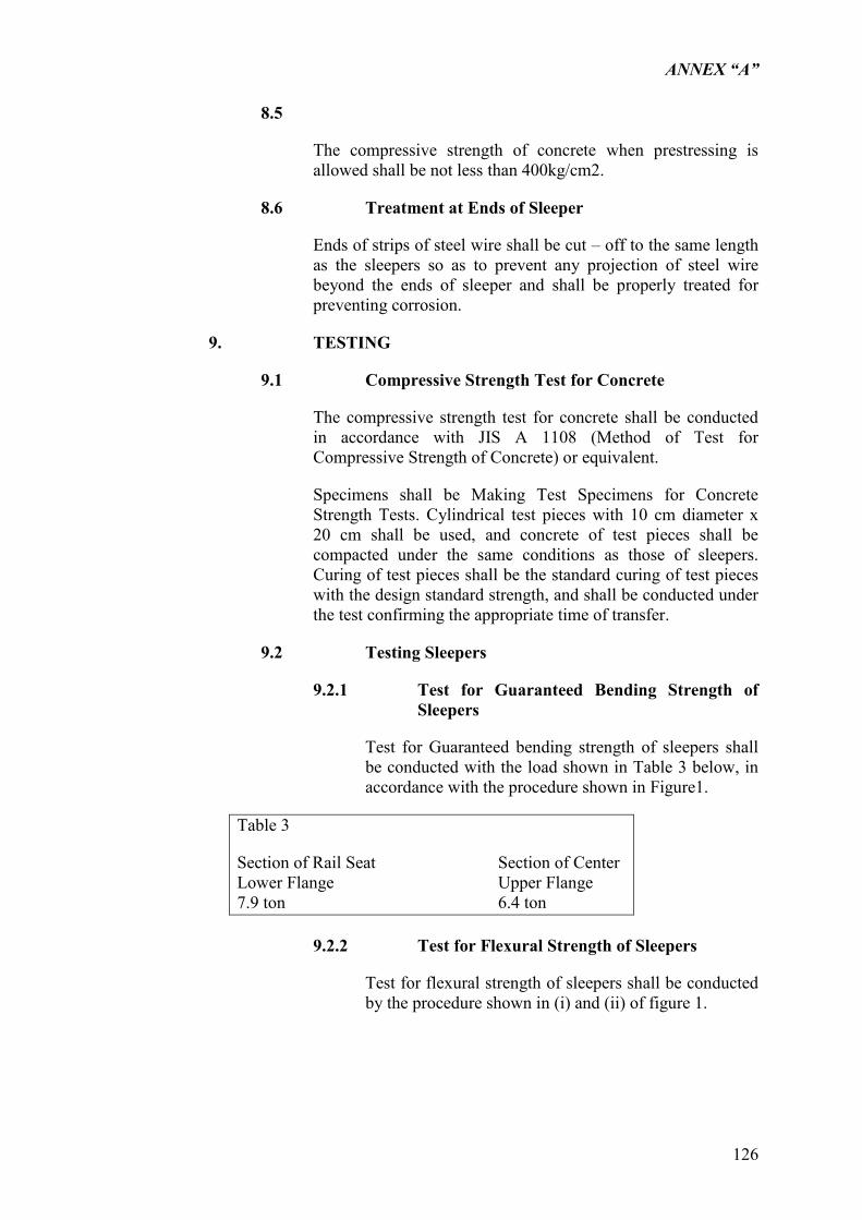
ANNEX “A”
126
8.5
The compressive strength of concrete when prestressing is allowed shall be not less than 400kg/cm2.
8.6 Treatment at Ends of Sleeper
Ends of strips of steel wire shall be cut – off to the same length as the sleepers so as to prevent any projection of steel wire beyond the ends of sleeper and shall be properly treated for preventing corrosion.
9. TESTING
9.1 Compressive Strength Test for Concrete
The compressive strength test for concrete shall be conducted in accordance with JIS A 1108 (Method of Test for Compressive Strength of Concrete) or equivalent.
Specimens shall be Making Test Specimens for Concrete Strength Tests. Cylindrical test pieces with 10 cm diameter x 20 cm shall be used, and concrete of test pieces shall be compacted under the same conditions as those of sleepers. Curing of test pieces shall be the standard curing of test pieces with the design standard strength, and shall be conducted under the test confirming the appropriate time of transfer.
9.2 Testing Sleepers
9.2.1 Test for Guaranteed Bending Strength of Sleepers
Test for Guaranteed bending strength of sleepers shall be conducted with the load shown in Table 3 below, in accordance with the procedure shown in Figure1.
Table 3
Section of Rail Seat Section of Center Lower Flange Upper Flange 7.9 ton 6.4 ton
9.2.2 Test for Flexural Strength of Sleepers
Test for flexural strength of sleepers shall be conducted by the procedure shown in (i) and (ii) of figure 1.

ANNEX “A”
127
9.2.3 Test for Guaranteed Pullout Strength and Test for Pullout Breaking Strength of cast shoulder.
Test for guaranteed pullout strength and test for pullout breaking strength of cast shoulder shall be conducted with the tension load gradually applied to bolts in conformity with the procedure shown in Figure 2.
10. INSPECTION
10.1 Frequency of Inspection for the Compressive Strength of Concrete
The frequency of inspection for the compressive strength of concrete shall conform to the following:
a. Inspection for conforming to the design standard strength shall be conducted at least once in every four hours of concrete mixing work if the mix proportion is not changed. But in inspection must be reformed each time the mix proportion is changed.
b. Inspection for confirming the compressive strength of concrete to determine the appropriate time of transfer shall be performed at least once for all sleepers in a lot which will be prestressed at the same time. However, inspection is required each time for the lot when the mix proportion is changed.
10.2 Acceptance
a. If the minimum compressive strength of 3 test pieces meets the provisions in Section 9.2, the lot representative by such test pieces shall be deemed to have successfully passed the test.
Should sufficiently reliable test results be available which indicate the relation between the compressive strength of concrete at the ages of 28 days and 7 days, the compressive strength at the age of 28 days may be received by conversion from the compressive strength at the age of 7 days predetermined by the test.
b. Guaranteed Flexural Strength of Sleepers and Guaranteed Pullout Strength of cast shoulder.
Inspection for the guaranteed flexural strength of sleepers and the guaranteed pullout strength of cast shoulder shall be conducted for the group of sleepers as one lot which was prestressed at the same time, and one specimen per lot shall be subjected to the test in this inspection. If the specimen is found to be conforming to the test requirements for
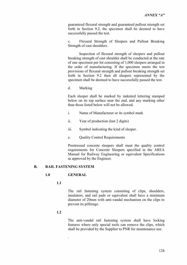
ANNEX “A”
128
guaranteed flexural strength and guaranteed pullout strength set forth in Section 9.2, the specimen shall be deemed to have successfully passed the test.
c. Flexural Strength of Sleepers and Pullout Breaking Strength of cast shoulders.
Inspection of flexural strength of sleepers and pullout breaking strength of cast shoulder shall be conducted at the rate of one specimen per lot consisting of 1,000 sleepers arranged in the order of manufacturing. If the specimen meets the test provisions of flexural strength and pullout breaking strength set forth in Section 9.2 then all sleepers represented by the specimen shall be deemed to have successfully passed the test.
d. Marking
Each sleeper shall be marked by indented lettering stamped below on its top surface near the end, and any marking other than those listed below will not be allowed.
i. Name of Manufacturer or its symbol mark
ii. Year of production (last 2 digits)
iii. Symbol indicating the kind of sleeper.
e. Quality Control Requirements
Prestressed concrete sleepers shall meet the quality control requirements for Concrete Sleepers specified in the AREA Manual for Railway Engineering or equivalent Specifications as approved by the Engineer.
B. RAIL FASTENING SYSTEM
1.0 GENERAL
1.1
The rail fastening system consisting of clips, shoulders, insulators, and rail pads or equivalent shall have a minimum diameter of 20mm with anti-vandal mechanism on the clips to prevent its pilferage.
1.2
The anti-vandal rail fastening system shall have locking features where only special tools can remove the clips, which shall be provided by the Supplier to PNR for maintenance use.
.

ANNEX “A”
129
1.3
The supplier of the rail fastening system shall provide the nominal positions of the cast iron settings in the concrete sleeper and shall supply the rail fastening components.
1.4
Track gauge shall be nominal 1,067 mm +/- 2 mm measured at 14mm below the rail head with the rails inclined at 1 in 40 +/- 2 degrees.
1.5
The rail fastening system shall be designed to suit 37 kg ASCE rail
1.6
The rail fastening system shall incorporate a 6 mm thick HIGH density Polyethylene rail pad of proven performance similar with the climate in the Philippines.
1.7
Toe load shall be minimum of 1,000 kgf +/- 10% when measured in a clip driving fixtures. The clip deflection shall be at least 11 mm at the nominal deflection.
1.8
The rail fastening system shall meet the current track performance requirements of the European norm, EN 13481-2
1.9
The rail fastening components per sleeper sets shall consist of the following:
1) 4 Nos type 2000 Anti-Vandal elastic rail clips.
2) 4 Nos Glass Reinforced Nylon Insulators
3) 4 Nos Spheroidal Graphite Iron shoulder inserts
4) 2 Nos HDPE Rail Pads 6mm thick.
1.10
The chemical and Mechanical Properties of the Rail fastening components shall be within the following ranges:
Spheroidal Graphite Iron Shoulder:
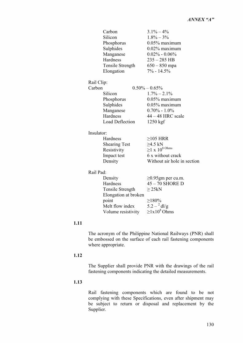
ANNEX “A”
130
Carbon 3.1% – 4% Silicon 1.8% – 3% Phosphorus 0.05% maximum Sulphides 0.02% maximum Manganese 0.02% - 0.06% Hardness 235 – 285 HB Tensile Strength 650 – 850 mpa Elongation 7% - 14.5% Rail Clip: Carbon 0.50% – 0.65%
Silicon 1.7% – 2.1% Phosphorus 0.05% maximum Sulphides 0.05% maximum Manganese 0.70% - 1.0% Hardness 44 – 48 HRC scale Load Deflection 1250 kgf
Insulator: Hardness ≥105 HRR Shearing Test ≥4.5 kN Resistivity ≥1 x 10⁸ Ohms
Impact test 6 x without crack Density Without air hole in section Rail Pad: Density ≥0.95gm per cu.m. Hardness 45 – 70 SHORE D Tensile Strength ≥ 25kN Elongation at broken point ≥180% Melt flow index 5.2 – 2 dl/g Volume resistivity ≥1x10⁸ Ohms
1.11
The acronym of the Philippine National Railways (PNR) shall be embossed on the surface of each rail fastening components where appropriate.
1.12
The Supplier shall provide PNR with the drawings of the rail fastening components indicating the detailed measurements.
1.13
Rail fastening components which are found to be not complying with these Specifications, even after shipment may be subject to return or disposal and replacement by the Supplier.
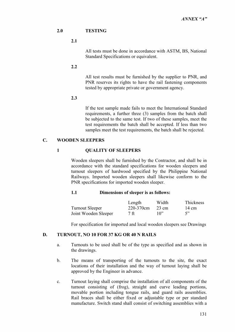
ANNEX “A”
131
2.0 TESTING
2.1
All tests must be done in accordance with ASTM, BS, National Standard Specifications or equivalent.
2.2
All test results must be furnished by the supplier to PNR, and PNR reserves its rights to have the rail fastening components tested by appropriate private or government agency.
2.3
If the test sample made fails to meet the International Standard requirements, a further three (3) samples from the batch shall be subjected to the same test. If two of these samples, meet the test requirements the batch shall be accepted. If less than two samples meet the test requirements, the batch shall be rejected.
C. WOODEN SLEEPERS
1 QUALITY OF SLEEPERS
Wooden sleepers shall be furnished by the Contractor, and shall be in accordance with the standard specifications for wooden sleepers and turnout sleepers of hardwood specified by the Philippine National Railways. Imported wooden sleepers shall likewise conform to the PNR specifications for imported wooden sleeper.
1.1 Dimensions of sleeper is as follows:
Length Width Thickness Turnout Sleeper 220-370cm 23 cm 14 cm Joint Wooden Sleeper 7 ft 10” 5”
For specification for imported and local wooden sleepers see Drawings
D. TURNOUT, NO 10 FOR 37 KG OR 40 N RAILS
a. Turnouts to be used shall be of the type as specified and as shown in the drawings.
b. The means of transporting of the turnouts to the site, the exact locations of their installation and the way of turnout laying shall be approved by the Engineer in advance.
c. Turnout laying shall comprise the installation of all components of the turnout consisting of (frog), straight and curve leading portions, movable portion including tongue rails, and guard rails assemblies. Rail braces shall be either fixed or adjustable type or per standard manufacture. Switch stand shall consist of switching assemblies with a
ANNEX “A”
132
throwing lever, a connecting bar, a switch lock and a movable switch sign, and shall be manually operated.
d. All tongue rails, frogs and guard rails shall be placed in accordance with the drawings and track work plan approved by the Engineer.
e. Switches shall be left in proper adjustment, special care being given to avoid the bending of the tongue rails for which appropriate protective measures should be taken by the contractor before they are installed in place.
f. All movable parts of turnouts shall be kept in well-cleaned condition by removing floating rusts and applying lubricant oil thereto so as to keep them movable freely.
g. Once turnouts are installed in place they shall be inspected by the Engineer.
h. For specification for turnouts, see “PART 7 TRACK MATERIALS” ”.
E. CRUSHED ROCK BALLAST
a. Ballast shall be supplied by the contractor.
b. For specifications for ballast, see “PART 7 TRACK MATERIALS”
F. FILLING MATERIALS (ITEM 204 DPWH, EMBANKMENT)
a. Filling materials for embankments shall be supplied by Contractor
G. THERMIT WELDING
a. Rails shall be completely welded by and with the Contractor supplying all the requirements for welding of rail by thermit process.
b. For thermit welding of rails, see section 5.7.
ANNEX “A”
133
5.4 PREPARATION AND HANDLING OF TRACK MATERIALS
5.4.1 PREPARATION
a. The Contractor shall obtain the approval of the Engineer on the track work schedule including the force to be employed and the speed with which the work will proceed. Prior to commencement of the work, the Contractor shall notify the Engineer at least five working days in advance so that adequate arrangements can be made by the Engineer for the execution of the work.
b. The Contractor shall obtain the approval of the Engineer on the centerline stakes for track improvement purpose before the commencement of track work. After the stakes for the track improvement have been approved by the Engineer the Contractor shall follow the stakes in the track laying, lining and surfacing.
c. No material shall be placed nor shall the track be laid on the subgrade until the sub-grade has been constructed and finished true to the line and planes according to the stakes set by the Contractor on the completed subgrade as approved by the Engineer.
d. When the prepared subgrade is used for the purpose of transporting materials and equipment by trucks and/or for the operation of heavy equipment it shall be with the approval of the Engineer. The sub-grade shall be restored to the original state by grading and compacting to the satisfaction of the Engineer at the Contractor‟s own cost before the track construction is commenced.
5.4.2 HANDLING OF TRACK MATERIALS
The Contractor shall take all precautions for the transport of track materials to the site of work and shall coordinate fully with the Engineer in advance on the locations and times of loading and unloading the track materials.
a. At the site, it is necessary to load or convey the rails by the rail carrier with derrick crane. When handling rails by hand using rail tongs, no attempt shall be made to throw the rails. Special care shall be taken in handling the tongue rails of turnouts so as not to cause any damage thereon.
b. Distribution of Rails
The Contractor shall distribute rails so that they can be laid without unnecessary additional handling taking care of the following:
Place rails base down, parallel with the track and with sufficient bearing to prevent bending or swinging.
To minimize the cutting of new full-length rails, short rails shall be distributed in proper places to provide for proper spacing on the curved track and locations for connections to switches.
ANNEX “A”
134
c. Handling of Wooden Sleepers
Preservative Treatment of Wooden Sleepers
(1) Any fabricating such as end trimming and, if required, adzing and boring or application of anti-cracking devices shall be performed at manufacturing plants of wood sleepers.
(2) As the turnout sleepers are not uniform in length, location of the switch components cannot be predicted, and they shall not be adzed or bored in advance.
d. Unloading and Stacking of Wooden Sleepers
Wooden sleepers shall not be unloaded by dropping or throwing them onto rails, rock or hard surfaces. Sleepers shall be handled with tongs and not with bars or sharp tools to avoid any damage.
e. Handling of Ballast
In loading and unloading ballast, the Contractor shall take precautions to prevent intrusion of soil or dust into the ballast.
(1) The ballast shall be loaded and unloaded by the Contractor. Care shall be taken not to destroy or disturb the grade stakes. The Contractor shall trim the ballast to conform to the standard ballast cross section plans. Any surplus ballast after trimming shall be disposed of as directed by the Engineer.
f. Handling of Concrete Sleepers
Care shall be taken in the transport, handling, placing, and tamping of ballast beneath the sleepers so as to avoid chipping and cracking of the concrete sleepers. Any sleeper which has been so damaged, and in the judgment of the Engineer is unserviceable, shall be removed and replaced.
ANNEX “A”
135
5.5 TRANSPORT AND STORAGE OF TRACK MATERIALS
a. The Contractor shall fully coordinate with the Engineer and obtain has approval on locations, methods and times of storage of track materials.
b. Rails and turnouts shall be placed on appropriate supports so as to prevent any damage or bents thereto. In station grounds, rails shall be stacked properly not to cause any hazard to train passage and off the tracks in a place convenient for distribution.
c. Joint bars, track bolts, spring washers and track spikes and accessories of turnouts shall be stored in the warehouses or sheds. If they are required to be stored outdoors, appropriate protective measures shall be taken against rainwater and other foreign matters that may cause any damage thereto.
d. Stacks of sleeper shall be appropriately supported and likewise protected from sparks or other fire hazards and undue damage by covering with appropriate tarpaulins. Concrete sleepers shall be protected inserts by means of a plastic cap wooden planks plug or other suitable device approved by the Engineer.
e. Caps or plugs shall be placed in position at the time of manufacture, left in place during shipping and not removed until fastenings are affixed to the sleepers.
f. Handling and transporting of concrete sleepers shall be done with utmost care so as not to incur undue cracks and/or chipping at edges. Sleepers shall not be unloaded by dropping or throwing unto rails, rocks or hard surfaces. Sleepers shall be handled with tongs and not with bars or sharp tools to avoid any damage. Any damaged sleeper resulting from mishandling shall be replaced.
g. In the case where the ballast is stored in the stockyard, the surface shall be graded, and vegetation and rubbish shall be removed prior to the stacking of ballast materials.
h. Quantities of materials classified by respective types stored at the site shall be ensured by the Contractor for the approval of the Engineer.
i. The Contractor shall be responsible for the security to prevent any Pilferage or damage to the materials stored at the site.
j. Other means of transport required to move track and other construction Materials rail shall furnished by the Contractor
ANNEX “A”
136
5.6 USE OF TRACK MATERIALS
a. Use of Rails
Specified short rails on the ordinary fish plates joint should be used on the curved track, in order to ensure even rail joints on both rails to connect with the turnouts. Rails less than 5 meters in length shall not be used.
Rails to be used on sharp curves shall be bent prior to the laying work.
When short rails are used on the curved track, the arrangement of short rails shall be approved by the Engineer in advance.
b. Cutting and Drilling of Rails
When available, the Contractor shall use a friction type rail saw for the cutting of rails. The surface to be cut shall be square to the centerline of rail. No rail shall be cut with gas torches under any circumstances.
When drilling a new bolt hole on the rail web as required to prepare the short rails, the drilling shall be carried out in accordance with the standard drilling practices.
Accurate positions in correct dimension of holes as specified on the drawings. No hole shall be punched or burned with a torch in the rails under any circumstances. After drilling, all the chips and burrs shall be neatly removed. No hole shall be drilled between the existing holes.
c. Laying of Sleepers
Concrete sleepers shall be laid only on track sections where specified or as directed by the Engineer. Use of concrete sleepers under rail joints shall be avoided.
Sleepers shall be laid square to the rail on the straight track and concentrically on the curved track in a uniform interval. Sleepers shall be laid at spacing as specified on the drawings. The bottom of the rail, the rail pad and the rails seats shall be ensured that all fastening components such as rail clips, ferrules, rail pads, etc. are complete and properly installed.
The centerline of the sleeper length shall coincide with the centerline of track alignment.
d. Laying of Rails
In laying the rails, the Contractor shall take the following precautions:
Use mechanical devices whenever possible and take utmost care to protect the workers from possible hazards.
In laying second hand rails, care shall be exercised to prevent a gap of more than 2mm and to align the rail within allowable gauge tolerance.
ANNEX “A”
137
Gauging of the track shall be carried out at least every third sleeper when the second line of rails is laid against the requisite track gauge plus required slack on the curved track.
The following are the radius of gauge on curve track:
RADIUS (m) SLACK (mm)
300 m - 0
300 – 175 m - 8 mm
<175 m - 15 mm
The increase or decrease of slack shall be at the transaction area, 5 m length minimum.
The required super elevation for curves shall be:
C = 8.40 V2/R
Cmax = 90 mm
e. Rail Joints (On location without welding)
Joints in the opposite rails shall be located evenly unless otherwise directed by the Engineer. In laying the rails on curves, care shall be taken to place the short rails on the location of inside rails so as to maintain even rail joints throughout the curves.
Rail joints on prestressed concrete sections shall be of the supported type and rail joints on wooden sections shall be of the suspended type.
Rail joints shall be provided at locations remote from road crossings, at least 5 m before crossing.
Provision of space allowance for expansion of rails shall follow the criteria to be made by the Engineer. Approved expansion shims of metal or fibre shall be used to provide for the proper space allowance between adjacent rail ends, and a rail thermometer shall be used to determine the proper thickness of shims to be inserted in accordance with rail temperature. After laying the rails and setting up rail joints, all records of expansion spaces set up on the rack shall be submitted to the Engineers for review and approval.
Contact surfaces between the rails and joint bars shall be greased, and those between joint bars and track bolts and on the threads of track bolts shall be lubricated just before laying the rails.
All rail joints shall be firmly bolted and fitted with approved spring washers. All bolts shall be tightened to the following torque before track is turned over to train operation:
Common Trackbolts 2,000 kg-cm (80 lb. rails)
ANNEX “A”
138
2,000 kg-cm (73 lb. rails)
1,600 kg-cm (65 lb. rails)
Bolts shall be tightened in the proper sequence to seat joints, beginning at the center of the joint and working both ways to the ends of the joint. When bolts are tightened, the surfaces of rail heads and gauge line of both rails shall be set coinciding with one another.
f. Track Spikes
Two (2) track spikes shall be used for fastening the rail to the sleeper. The existing sleepers of insufficient bearing for the track spikes shall be reworked and the holes shall be plugged with wooden inserts. Track spikes shall be provided as shown in the drawings.
g. Screw Spikes
Four (4) screw spikes shall be used for fastening rails to bridge sleepers.
ANNEX “A”
139
5.7 WELDING OF RAILS
a. Inspection and Classification of Existing Rail for Welding
A field inspection shall be made on rails in service, and all rails containing severe engine drive burns, anchor nicks, excessive wear on the rail base or other visible flaws shall be rejected for welding. It is recommended that the rail selected for welding be picked up in such a manner that the rail wear pattern in the continuous welded rail (CWR) string will remain approximately the same as it was in original service. One method to keep the rails in an orderly manner with respect to their wear pattern is to mark the north or west rail 2-4-6 etc.
Remove jointed rail in sections 60 meter long, then the joint bars are removed. Joint bars, bolts and washers may be salvaged as repair material or the rail may be cropped as a unit. The rail is carefully inspected after cropping, and rail not suitable for welding is removed. Some engine drive burns may be oxyacetylene welded to upgrade the rail.
When the rail arrives at the welding site, a qualified rail inspector shall carefully inspect the rail for head wear, corrosion, base wear, sweeps, kinks or any other defect that may have escaped detection in the previous inspection. Rail for each CWR string must be matched to have the same height and width within 1.6 mm (1/16 in.).
The Contractor has the option for any methodology to achieve efficient welding operation while continuing to maintain rail traffic, subject however to the approval of the Engineer. The Engineer will not allow the use of a Holland-in-Track flash butt welder.
It is recommended that the rail be stored straight and level on a firm base and each tier stripped in four places.
(1) Minimum rail length should be 59 meter after cropping.
(2) Excess oils, grease, tars, etc., must be removed from the rail before welding.
(3) Maximum head flow should be 6.4mm (1/4 in.) on each side of the rail if shears are used to remove the upset metal.
(4) Grade crossing rails must be free of corrosion or rejected for welding except for yards or similar tracks.
(5) Bolt holes and bond holes must be eliminated by cropping.
(6) After cropping, both ends of the rail should be inspected for piped condition.
Recommended Rail Grading Classification:
Recommended Rail Grading Classification
Rail Weight MAXIMUM RAIL WEAR General Rail Use and
Condition Top Gauge
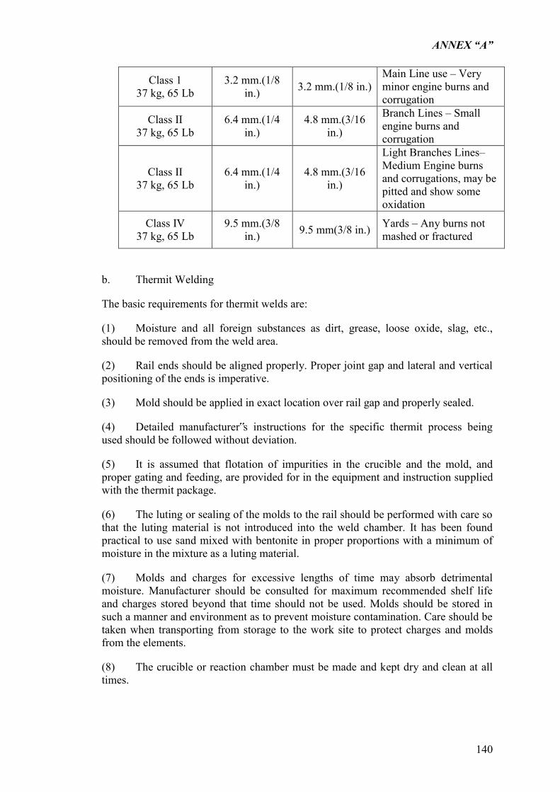
ANNEX “A”
140
Class 1 37 kg, 65 Lb
3.2 mm.(1/8 in.) 3.2 mm.(1/8 in.)
Main Line use – Very minor engine burns and corrugation
Class II 37 kg, 65 Lb
6.4 mm.(1/4 in.)
4.8 mm.(3/16 in.)
Branch Lines – Small engine burns and corrugation
Class II 37 kg, 65 Lb
6.4 mm.(1/4 in.)
4.8 mm.(3/16 in.)
Light Branches Lines– Medium Engine burns and corrugations, may be pitted and show some oxidation
Class IV 37 kg, 65 Lb
9.5 mm.(3/8 in.) 9.5 mm(3/8 in.) Yards – Any burns not
mashed or fractured
b. Thermit Welding
The basic requirements for thermit welds are:
(1) Moisture and all foreign substances as dirt, grease, loose oxide, slag, etc., should be removed from the weld area.
(2) Rail ends should be aligned properly. Proper joint gap and lateral and vertical positioning of the ends is imperative.
(3) Mold should be applied in exact location over rail gap and properly sealed.
(4) Detailed manufacturer‟s instructions for the specific thermit process being used should be followed without deviation.
(5) It is assumed that flotation of impurities in the crucible and the mold, and proper gating and feeding, are provided for in the equipment and instruction supplied with the thermit package.
(6) The luting or sealing of the molds to the rail should be performed with care so that the luting material is not introduced into the weld chamber. It has been found practical to use sand mixed with bentonite in proper proportions with a minimum of moisture in the mixture as a luting material.
(7) Molds and charges for excessive lengths of time may absorb detrimental moisture. Manufacturer should be consulted for maximum recommended shelf life and charges stored beyond that time should not be used. Molds should be stored in such a manner and environment as to prevent moisture contamination. Care should be taken when transporting from storage to the work site to protect charges and molds from the elements.
(8) The crucible or reaction chamber must be made and kept dry and clean at all times.
ANNEX “A”
141
(9) Partial welding portions should never be used because of the possibility of material segregation and the need for proper metal supply to the weld. Two weld charges should never be mixed.
(10) It is recommended that welding not be performed during precipitation of any kind unless adequate precautions are taken to completely protect the crucible, mold, and adjacent rail from moisture.
(11) If temperature conditions are such that rapid contraction or expansion of rail is taking place, welding should be avoided unless a rail puller/expander is used to maintain the gap spacing and hold the rails in position until the weld metal is below 371 deg. C (700 deg. F).
(12) If compromise welds are being made, only molds and charges designed for the specific transition in rail size shall be used.
(13) In the case of the processes in which the filler material is tapped manually, the metal shall not be tapped until the reaction is completed and the slag has separated from the filler material.
(14) The period of time immediately following the pouring of the metal is critical to production of a good weld. During the first three minutes the rail should not be disturbed in any manner. After that, at a time recommended by the manufacturer of the charge used, the slag basin and mold may be removed, and the excess Ballast shall be well packed with metal removed. If chisel cutting is performed, the rail must be adequately supported; however, it is recommended that excess metal be removed by shearing. Finish grinding the contours should be performed only after weld metal has cooled below 316 deg. C (600 deg. F).
In order to minimize mechanical strains and stresses on the weld metal, it is recommended that a rail puller/expander be used to hold the rails in place on either side of the new weld. They should be left in place until the weld metal has cooled to below 371 deg. C (700 deg. F).(15)
(16) If strap bars are used on the joint after welding, only bars designed with proper clearance of cast-on fins should be used.
ANNEX “A”
142
5.8 TRACK LAYING
Track laying shall be performed by the Contractor conforming with alignment, profile, track structure, and gauge of track specified in the drawings. Track laying shall be carried out by the following method as directed by the Engineer.
a. Once the formation is ready for track laying, ballast shall be unloaded and spread to a design of 200 mm after which it shall be rolled.
b. PC sleeper hooked to a spreader which pre-sets the spacing of the sleepers shall then be laid over the ballast. After aligning the running sleepers, the speaker shall be detached.
c. Parts which shall be welded into 60 meter panels shall be laid on top of the sleepers and later fastened to the sleeper with slips. Rails shall be fasten temporarily together using fish plates and bolts.
d. More ballast shall be unloaded and evenly spread using a ballast regulator.
e. A tamping machine shall tamp the ballast and align and level the tracks.
f. More ballast shall be unloaded and spread by the ballast regulator where it is needed.
g. The tamping machine shall make another pass over the track to further tamp, align and level the tracks.
h. Spot unloading of ballast shall be done where it is required.
i. Final tamping, aligning and leveling of the tracks to the final grade shall be undertaken after which ballast is trimmed to conform to the standard ballast section in the drawings. The Contractor shall dispose of any surplus ballast after trimming as directed by the Engineers.
j. The rails shall be welded into 120 m panelafter removing the fish plates.
5.9 STORAGE OF MATERIALS DERIVED FROM THE WORK
Various track materials derived as the consequence of the work shall be properly stored in the location as directed by the Engineer for which proper inventories shall be made and kept until proper turnover of such materials has been made to PNR.
5.10 CONDITIONING OF TRACKS
After track laying, the overall conditioning of the tracks shall be carried out to finish the track construction by overall tamping and trimming of ballast in accordance with the specified alignment, cross-sections, grade based on grade stakes, super elevation, track gauge and slack.
ANNEX “A”
143
5.11 TOLERANCE OF TRACK CONSTRUCTION WORK AND TRACK REHABILITATION WORK
The measurement of irregularities of tracks constructed in place shall conform to the following conditions:
a. Measuring instrument to be used shall be calibrated and approved by the Engineer in advance.
b. Track irregularities shall be measured in the static condition.
c. The measurement of track irregularities shall be conducted every 5 meters along the track centerline.
d. The irregularities are indicated by the expressions as shown in the following where measuring unit it is in millimeter (mm). Irregularities in super elevation, slack of track gauge and ordinates from grade lines are the measured value minus the specified value.
5.11.1 TRACK GAUGE
Excessive values are expressed with (+) sign, while values in shortage are expressed with (-) sign.
5.11.2 CROSS LEVEL
The left hand side rail on the straight track and the inner rail on the curved track are used as the base of leveling; a (+) sign expenses the higher and a (-) sign expenses the lower irregularities of the opposite rail.
5.11.3 ALIGNMENT
Measurement shall be conducted by 10 m. base at the gauge line on the left hand side rail on the straight track and on the outer rail on the curved track where the (+) sign expresses outward irregularities and the (-) sign expresses the inward irregularities of track alignment.
5.11.4 LONGITUDINAL LEVEL
Measurement shall be conducted by a 10 m. base at the surface of rail expressing upward irregularities with a (+) sign and downward irregularities with a (-) sign.
5.11.5 MEASUREMENT
The measurement of alignment and longitudinal level shall be conducted using a string with an effective length of 10 meters to be extended with a tension of 2 kg, and the measurement of irregularities shall be made at the middle of the string. In measuring the longitudinal level, 1.0 millimeter shall be deducted from the measured value as the sag of the string.
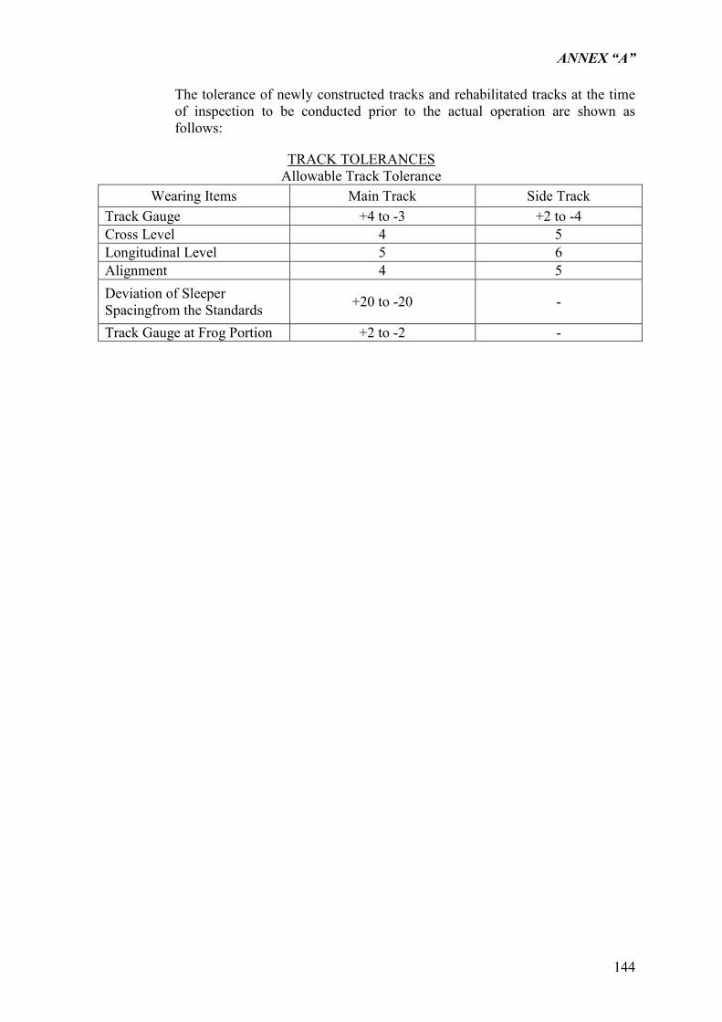
ANNEX “A”
144
The tolerance of newly constructed tracks and rehabilitated tracks at the time of inspection to be conducted prior to the actual operation are shown as follows:
TRACK TOLERANCES Allowable Track Tolerance
Wearing Items Main Track Side Track Track Gauge +4 to -3 +2 to -4 Cross Level 4 5 Longitudinal Level 5 6 Alignment 4 5 Deviation of Sleeper Spacingfrom the Standards +20 to -20 -
Track Gauge at Frog Portion +2 to -2 -
ANNEX “A”
145
5.12 TRIAL TRAIN OPERATION ON NEWLY CONSTRUCTED AND REHABILITATED TRACKS
In the case where trial operation is carried out on the newly constructedtracks, the operation shall be performed by assigning a person responsible for the operation under the following guidelines:
a. Prior to the trial run, track irregularities under various items as specified elsewhere shall be measured by the Contractor, and the records of the result shall be submitted by the Contractor to the Engineer for review.
b. Prior to the trial run, instruments to measure the settlement of track thereof shall be installed by the Contractor according to the instructions given by the Engineer, and their installations shall be examined by the Engineer for approval.
c. Upon the trial run, the Contractor shall measure the settlement of track by the aforementioned instruments installed. The records of the result shall be submitted to the Engineer again for review.
d. After the trial run has been conducted, the Contractor shall carry out the track conditioning again only at such locations instructed by the engineer as the results of the trial run, the second trial run shall be carried out and the records of second measurements shall be submitted to the Engineer again for review.
e. After the results of measurements are approved as being satisfactory to the Engineer, all temporary structures and measuring instruments provided for the trial run shall be removed by the Contractor under the direction of the Engineer.
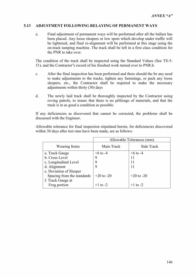
ANNEX “A”
146
5.13 ADJUSTMENT FOLLOWING RELAYING OF PERMANENT WAYS
a. Final adjustment of permanent ways will be performed after all the ballast has been placed. Any loose sleepers or low spots which develop under traffic will be tightened, and final re-alignment will be performed at this stage using the on-track tamping machine. The track shall be left in a first class condition for the PNR to take over.
The condition of the track shall be inspected using the Standard Values (See TS-5-51), and the Contractor‟s record of his finished work turned over to PNR.b.
c. After the final inspection has been performed and there should the be any need to make adjustments to the tracks, tighten any fastenings, or pack any loose sleepers, etc., the Contractor shall be required to make the necessary adjustments within thirty (30) days
d. The newly laid track shall be thoroughly inspected by the Contractor using roving patrols, to insure that there is no pilferage of materials, and that the track is in as good a condition as possible.
If any deficiencies as discovered that cannot be corrected, the problems shall be discussed with the Engineer.
Allowable tolerance for final inspection stipulated herein, for deficiencies discovered within 30 days after test runs have been made, are as follows:
Allowable Tolerances (mm)
Wearing Items Main Track Side Track
a. Track Gauge b. Cross Level c. Longitudinal Level d. Alignment e. Deviation of Sleeper Spacing from the standards f. Track Gauge at Frog portion
+6 to -4 9 9 9 +20 to -20 +1 to -2
+6 to -4 11 11 11 +20 to -20 +1 to -2
ANNEX “A”
147
5.14 MEASUREMENT AND PAYMENT
5.14.1 METHOD OF MEASUREMENT
5.14.1.1
The quantity of new or reconditioned rails to be paid shall be the number of pieces of installed 37 kg/m x meter complete with angle bars, track bolts and washers.
5.14.1.2
The quantity of PC sleepers to be paid shall be the number of pieces installed complete with rail fasteners which shall be supplied by the winning bidder.
5.14.1.3
The quantity of turnout sleepers to be paid shall be the number of sets installed complete with track spikes.
5.14.1.4
The quantity of ballast to be paid shall be the number of cubic meters unloaded at site and accepted by the Engineer. The ballast while still on the ballast-wagons shall be inspected and checked for its “water level” volume which shall be the basis for measurement. Prior to unloading the Contractor shall level the top surface of the ballast on the wagons to facilitate volume calculation. The costs incurred in hauling the ballast from the approved source or crushing plant is construed to have included in the unit price offered by the Contractor. The distribution cost and, after installation of tracks, the tamping, lifting, leveling and aligning costs are likewise presumed to have been included in the unit price of ballast as offered.
5.14.1.5
The quantity of rail welding to be measured for payment shall be the number of welded rail joints completed and accepted by the Engineer. The work includes all collection, transport, handling, assembly and laying of all necessary materials in positions. The works also include all cutting of closure and joining to abutting sections, all welding, trimming and grinding procedures.
5.14.1.6
The quantity of new turnouts/diamond crossings to be measured for payment shall be number of sets supplied and installed which shall include the supply and installation of sleepers, angle bars, track spikes, track bolts and washers. The cost of tamping using hand tampers shall be included in the unit price per set as offered by the Contractor.

ANNEX “A”
148
5.14.1.7 Basis of Payment
The quantities, determined as provided above, shall be paid for at the Contract Unit Price for the pay items listed and shown in the Bill of Quantities. The prices and payments shall be full compensation for furnishing and placing all materials including all labor, fools, equipment and incidentals necessary to complete the works prescribed in this Section.
ANNEX “A”
149
PART 6 MISCELLANEOUS WORKS
6.1 FENCING
6.1.1 SCOPE
This work shall consist of furnishing and constructing concrete pile and concrete panel for fencing in accordance with the details, and at the locations, shown on the Drawings or as required by the Engineer.
6.1.2 MATERIAL REQUIREMENTS
6.1.2.1 Concrete
Concrete pile and concrete panel shall be made of Class “B” Concrete, in accordance with Section 4.1, Concrete Works. The concrete pile posts shall be cast to the length shown on the detailed Drawings, and shall have a smooth surface finish. Concrete panel shall be cast to the sections or dimensions shown on the detailed Drawings and shall have a smooth surface finish.
6.1.2.2
Steel Reinforcement - Steel reinforcement for concrete pile posts and concrete panel shall conform to the provisions of Subsection 4.1.7.1, Reinforcing Steel.
6.1.3 CONSTRUCTION REQUIREMENTS
The contractor shall perform such clearing and grubbing as may be necessary to construct the fence to the required grade and alignment. Fence shall generally follow the contour of the ground. Grading shall be performed where necessary to provide a neat appearance.
6.1.3.1
Erection of Pile PostThe pile post shall be driven and erected in vertical position true to line and grade and shall be adequately supported prior to driving. The pile posts shall be erected to the height and location shown on the Drawings or as ordered by the Engineer. After driving is completed, all loose and displaced materials shall be cleaned and removed from around the piles with method approved by the Engineer. The driving of concrete pile post shall be done in accordance with Section 4.1, Piling.
6.1.3.2
Concrete panel shall be installed and constructed as shown on the Drawings and the method approved by the Engineer.
ANNEX “A”
150
6.2 CEMENT MORTAR
6.2.1 SCOPE
a. General
This work shall consist of preparing and furnishing mortar in accordance with these Specifications for masonry and for any other incidental work. The work under this section shall also be in accordance with Section 4.1 – Concrete Works for Structures.
b. Composition
Unless otherwise indicated on the drawings, masonry mortar shall be composed of one part Portland cement and two parts fine aggregate by volume to which hydrated lime may be added in an amount equal to 10 percent of the cement by weight. An air-entraining admixture may be used.
6.2.2 MATERIALS
Type 1 portland cement conforming to AASHTO M85 may be used.
Masonry cement shall conform to the requirements of ASTM C91.
Fine aggregate shall conform to the requirements of AASHTO T71.
Hydrated lime shall meet the requirements for residue, popping and pitting, and water retention shown for type N lime in ASTM C207.
Water shall conform to the requirements of AASHTO T26.
Air-entraining agents shall be as approved by the Engineer.
6.2.3 CONSTRUCTION REQUIREMENTS
All the materials except the water shall be mixed, either in a tight box or in an approved mortar mixer, until the mixture assumes a uniform color, after which the water shall be added and the mixing continued.
Mortar shall be mixed only in those quantities required for immediate use.
Mortar that is not used within 45 minutes after the water has been added shall be discarded.
ANNEX “A”
151
6.3 STONE MASONRY
6.3.1 SCOPE
This work shall consist of stone masonry in minor structures, slope protection around the drainage structures, in the retaining walls, and in other places where called for on the drawings or ordered in writing by the Engineer. The masonry shall be constructed on the prepared foundation bed in accordance with these Specifications and the specifications for other work items involved and in conformity with the lines, grades, sections, and dimensions shown on the drawings or required by the Engineer.
6.3.2 MATERIALS
a. Stone
The stone shall be clean, hard, and of a kind known to be durable, and shall be subject to the Engineer‟s approval. Adobe blocks shall not be used unless otherwise specified.
Unless other sizes are shown on the drawings, stones shall have thicknesses of not less than 15 cm, widths of not less than one and one half times their respective thicknesses, and lengths of not less than one and one half times their respective widths.
Each stone shall be of good shape and free of depressions and projections that might weaken or prevent it from being properly bedded.
The stone shall be dressed to remove any thin or weak portions. Face stones shall be dressed to provide bed and joint lines that do not vary more than 2 cm from true lines and to ensure the meeting of bed and joint lines without the rounding of the corners of the stones in excess of 3 cm in radius. Bed surfaces of face stones shall be approximately normal to the faces of the stones for about 8 cm and from this point may depart from a normal plane not to exceed 5 cm in 30 cm.
Face stones shall be pitched to line along all beds and joints. The maximum projections of rock faces beyond pitch lines shall not be more than 5 cm.
b. Mortar
The mortar shall conform to the requirements of Section 6.4.
6.3.3 CONSTRUCTION REQUIREMENTS
a. Selection and Placing
When the masonry is to be placed on a prepared foundation bed, the bed shall firm and normal to, or in steps normal to, the face of the wall, and shall have been approved by the Engineer before any stone is placed.
ANNEX “A”
152
Care shall be taken to prevent the bunching of small stones or stones of the same size. Large stones shall be used in the corners.
All stones shall be cleaned thoroughly and wetted immediately before being set, and the bed which is to receive them shall be cleaned and moistened before the mortar is spread. They shall be laid with their longest faces horizontal in full beds of mortar, and joints shall be flushed with mortar.
The exposed faces of individual stones shall be parallel to the faces of the walls in which the stones are set.
The stones shall be so handled as not jar or displace the stones already set. Suitable equipment shall be provided for setting stones larger than those that can be handled by two men. The rolling or turning of stones on the walls will not be permitted. If a stone is loosened after the mortar has taken initial set, it shall be removed, the mortar cleaned off, and the stone relaid with fresh mortar.
b. Beds and Joints
Bed for face stones may vary from 2 cm to 5 cm in thickness. They shall not extend in an unbroken line through more than five stones. Joints may vary from 2 cm to 5 cm in thickness. They shall not extend in an unbroken line through more than two stones. They may be at angles with the vertical from 0 to 45. Face stone shall bond at least 15 cm longitudinally and 5 cm vertically. At no place shall corners of four stones be adjacent to each other.
Cross beds for vertical faced walls shall be level, and for battered walls may vary from level to normal to the batter line of the face of the wall.
c. Headers
Headers shall be distributed uniformly throughout the wall of structures so as to form at least one fifth of the exposed faces. They shall be of such lengths as to extend from the front face of the wall into the backing at least 30 cm.
When a wall is 45 cm or less in thickness, the headers shall extend entirely from front to back face.
d. Backing
The backing shall be built chiefly of large stones and in a workmanlike manner. The individual stones composing the backing and hearting shall be wall bonded with the stones in the face wall and with each other. All openings and interstices in the backing shall be filled completely with mortar or with spalls surrounded completely by mortar.
e. Pointing
Both bed and vertical joints shall be finished as shown on the drawings or as directed by the Engineer. The mortar in joints on top surfaces shall be crowned slightly at the center of the masonry to provide drainage.
ANNEX “A”
153
f. Coping
Copings, if called for, shall be as shown on the drawings. Where copings are not called for, the top of the wall shall be finished with stones wide enough to cover the top of the wall from 45 cm to 1 meter in length, and of random heights, with a minimum height of 15 cm. Stone shall be laid in such a manner that the top course is an integral part of the wall. The tops of the top courses of stone shall be pitched to line in both vertical and horizontal planes.
g. Weep Holes
All walls and abutments shall be provided with weep holes. Unless otherwise shown on the drawings or directed by the Engineer, the weep holes shall be placed at the lowest points where free outlets can be obtained and shall be spaced not more than 2 meters center to center.
h. Cleaning Exposed Faces
Immediately after laid, and while the mortar is fresh, all fresh stones shall be thoroughly cleaned of mortar stains and shall be kept clean until the work is completed.
i. Curing
In hot or dry weather the masonry shall be satisfactorily protected from the sun and shall be kept wet for a period of at least three days after completion.
ANNEX “A”
154
6.4 DEMOLITION WORK
6.4.1 DESCRIPTION
This section shall be applied to the general demolition work of structures, such as concrete, steel structure, timber and drainage and others to be executed under the Contract
6.4.2 GENERAL PROVISIONS
The contractor shall be deemed to have satisfied himself as to the site condition and others whatsoever, and to include in his unit prices to cover all risk for any contingencies that may arise during or in connection with the work.
The demolition work shall be carried out by the approved method and equipment such as concrete breaker, gascutter, hydraulic jack, compressed air disconnector, or manpower but no blasting shall be used unless approved in writing by the Engineer.
The Contractor shall provide suitable equipment, skillful labors and appropriate temporary works such as scaffoldings to ensure the safety in his demolition works as well as the adjacent area.
The Contractor shall demolish all the structural members above the formation level, on which the subsequent and permanent works under this Contract will be constructed. To this end, the temporary work such as excavation shall be conducted by the Contractor.
6.4.3 MATERIALS REQUIREMENT
a. Reusable Steel Structures
The Contractor shall, prior to the dismantling work of any steel members classified as reusable, submit his scheme or method of operation in disconnecting any members of the steel structures for the approval of the Engineer.
The Contractor shall not be allowed to cut the steel members by gas cutter but to disconnect the bolts, or rivets with due care thereby avoiding any damage to the steel parts. If any difficulty in disconnecting the steel members are encountered, the Contractor shall coordinate with the Engineer about his methodology before any dismantling activity is to be undertaken by him.
All the reusable steel structures, shall be after dismantling operation, sorted in a proper manner, transported and unloaded with care to Caloocan stockyard upon the instructions of the Engineer.
b. Unusable Steel Structures

ANNEX “A”
155
The Contractor shall be responsible for the dismantling of steel structures classified as scrap and shall be removed from the site, transported and unloaded at the Caloocan stockyard.
The Contractor will be allowed to cut the steel members considered as scrap, to facilitate for the easy and convenient dismantling and transporting operation.
c. Concrete and Other Members
a. After demolishing, these members as debris shall be removed from the site as soon as possible and dumped at the disposal area approved by the Engineer.
b. These demolished members shall be broken to small pieces not more than 50 cm, before disposal.
d. Pavement and Earth
Pavement and excessive earth in the area shown on the Drawing shall be removed in a proper manner and method approved by the Engineer and dumped at the disposal area designated by the Engineer.
6.4.4 CONSTRUCTION METHOD
The Contractor shall prior to the commencement of any work herein submit his proposal of work method for the Engineer‟s approval, including temporary works such as formwork, support, scaffolding, etc.
The Contractor shall perform the work described above, within and adjacent to the railway, on the right-of-way as shown on the drawings or as directed by the Engineer. All materials recovered from demolition shall remain the property of the Employer unless specifically provided otherwise in the Contract Documents except materials resulting from the demolition structures. All designated salvageable material shall be removed, without unnecessary damage, in sections or pieces which may be readily transported, and shall be stored by the Contractor at specified places on the project as directed by the Engineer. Basements or cavities left by structure removal shall be filled with acceptable material to the level of the surrounding ground.
6.4.4.1 Performance of this work under the Contract shall be measured by payment
The obligation will also include salvage of materials, removed, their custody, preservation, storage on the right-of-way, and disposal as provided herein, except for the substructure materials.
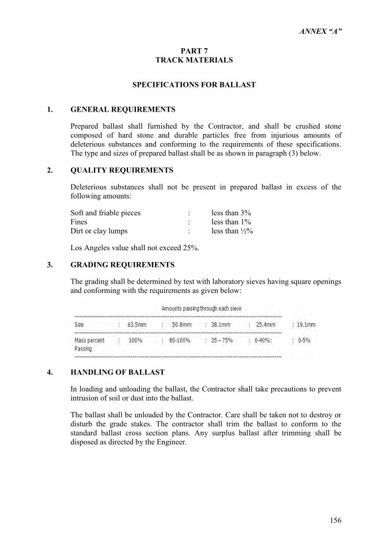
ANNEX “A”
156
PART 7 TRACK MATERIALS
SPECIFICATIONS FOR BALLAST
1. GENERAL REQUIREMENTS
Prepared ballast shall furnished by the Contractor, and shall be crushed stone composed of hard stone and durable particles free from injurious amounts of deleterious substances and conforming to the requirements of these specifications. The type and sizes of prepared ballast shall be as shown in paragraph (3) below.
2. QUALITY REQUIREMENTS
Deleterious substances shall not be present in prepared ballast in excess of the following amounts:
Soft and friable pieces : less than 3% Fines : less than 1% Dirt or clay lumps : less than ½%
Los Angeles value shall not exceed 25%.
3. GRADING REQUIREMENTS
The grading shall be determined by test with laboratory sieves having square openings and conforming with the requirements as given below:
4. HANDLING OF BALLAST
In loading and unloading the ballast, the Contractor shall take precautions to prevent intrusion of soil or dust into the ballast.
The ballast shall be unloaded by the Contractor. Care shall be taken not to destroy or disturb the grade stakes. The contractor shall trim the ballast to conform to the standard ballast cross section plans. Any surplus ballast after trimming shall be disposed as directed by the Engineer.
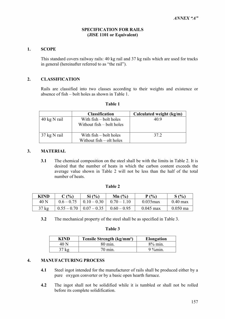
ANNEX “A”
157
SPECIFICATION FOR RAILS
(JISE 1101 or Equivalent)
1. SCOPE
This standard covers railway rails: 40 kg rail and 37 kg rails which are used for tracks in general (hereinafter referred to as “the rail”).
2. CLASSIFICATION
Rails are classified into two classes according to their weights and existence or absence of fish – bolt holes as shown in Table 1.
Table 1
Classification Calculated weight (kg/m) 40 kg N rail With fish – bolt holes
Without fish – bolt holes
40.9
37 kg N rail With fish – bolt holes Without fish – olt holes
37.2
3. MATERIAL
3.1 The chemical composition on the steel shall be with the limits in Table 2. It is desired that the number of heats in which the carbon content exceeds the average value shown in Table 2 will not be less than the half of the total number of heats.
Table 2
KIND C (%) Si (%) Mn (%) P (%) S (%) 40 N 0.6 – 0.75 0.10 – 0.30 0.70 – 1.10 0.035max 0.40 max 37 kg 0.55 – 0.70 0.07 – 0.35 0.60 – 0.95 0.045 max 0.050 ma
3.2 The mechanical property of the steel shall be as specified in Table 3.
Table 3
KIND Tensile Strength (kg/mm²) Elongation 40 N 80 min. 8% min. 37 kg 70 min. 9 %min.
4. MANUFACTURING PROCESS
4.1 Steel ingot intended for the manufacturer of rails shall be produced either by a pure oxygen converter or by a basic open hearth furnace.
4.2 The ingot shall not be solidified while it is tumbled or shall not be rolled before its complete solidification.
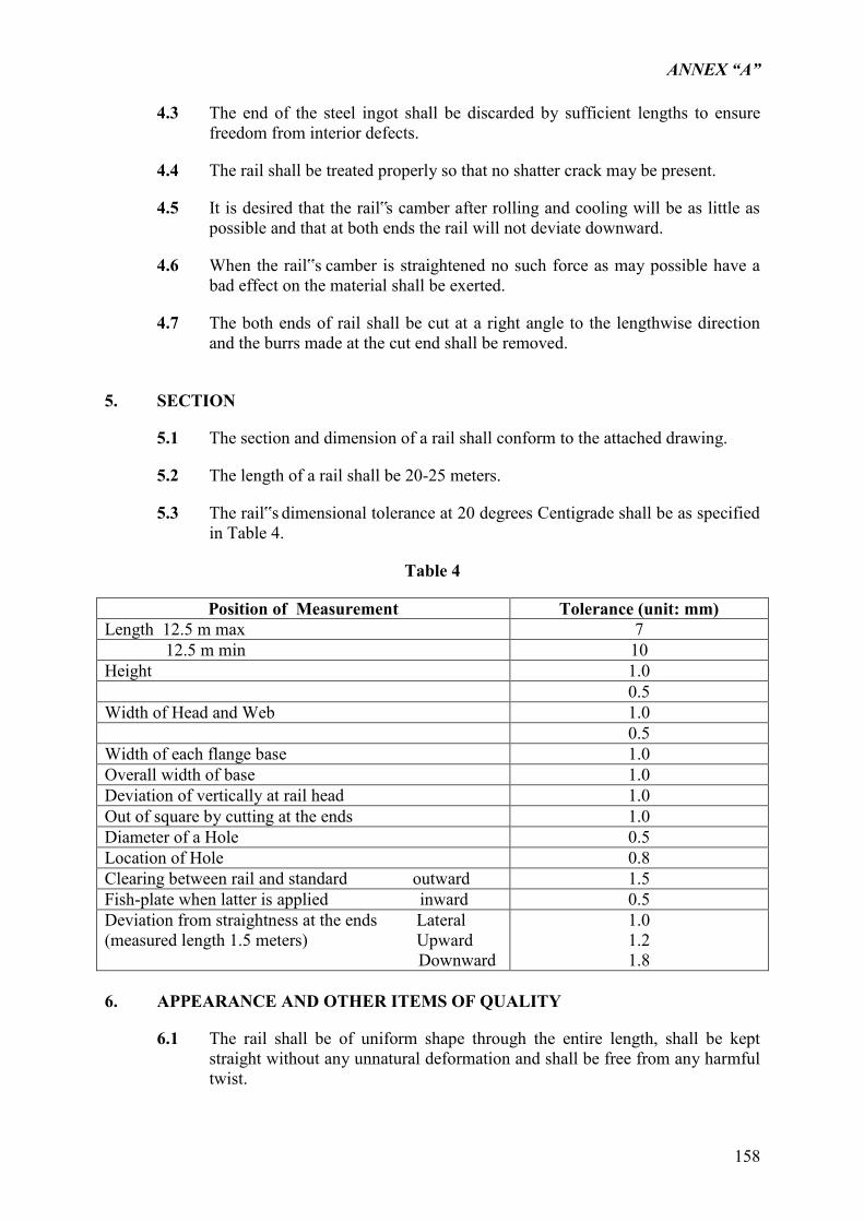
ANNEX “A”
158
4.3 The end of the steel ingot shall be discarded by sufficient lengths to ensure freedom from interior defects.
4.4 The rail shall be treated properly so that no shatter crack may be present.
4.5 It is desired that the rail‟s camber after rolling and cooling will be as little as possible and that at both ends the rail will not deviate downward.
4.6 When the rail‟s camber is straightened no such force as may possible have a bad effect on the material shall be exerted.
4.7 The both ends of rail shall be cut at a right angle to the lengthwise direction and the burrs made at the cut end shall be removed.
5. SECTION
5.1 The section and dimension of a rail shall conform to the attached drawing.
5.2 The length of a rail shall be 20-25 meters.
5.3 The rail‟s dimensional tolerance at 20 degrees Centigrade shall be as specified in Table 4.
Table 4
Position of Measurement Tolerance (unit: mm) Length 12.5 m max 7 12.5 m min 10 Height 1.0 0.5 Width of Head and Web 1.0 0.5 Width of each flange base 1.0 Overall width of base 1.0 Deviation of vertically at rail head 1.0 Out of square by cutting at the ends 1.0 Diameter of a Hole 0.5 Location of Hole 0.8 Clearing between rail and standard outward 1.5 Fish-plate when latter is applied inward 0.5 Deviation from straightness at the ends Lateral (measured length 1.5 meters) Upward Downward
1.0 1.2 1.8
6. APPEARANCE AND OTHER ITEMS OF QUALITY
6.1 The rail shall be of uniform shape through the entire length, shall be kept straight without any unnatural deformation and shall be free from any harmful twist.
ANNEX “A”
159
6.2 The rail shall not have any such defects as harmful crack and flaw on its surface.
6.3 In the cross-section of rail and in the inside surface of fish-bolt hole, there shall not exist any internal defects such as the harmful pipe and the segregation of impurities.
6.4 Fish-bolt holes shall be drilled accurately and smoothly in the web at both ends of rail as shown in the attached drawing.
6.5 The rail with fish-bolt holes shall be chamfered around rail head and upper fillet at the periphery of fish-bolt hole shown in the attached drawing.
7. TEST AND INSPECTION
7.1
The tools to be used to inspect the shape and dimensions shall be those designated or approved by PNR.
7.2 Chemical; analysis and inspection:
7.2.1 The specimen to be used in chemical analysis shall be sampled in accordance with JIS G 0303 “General Rule for Inspection of steel.” or equivalent.
7.2.2 The method of analysis shall conform to the following and the result of analysis shall conform to the provisions specified in Table 2.
JIS G 1211 (General rules concerning the method of iron and steel analysis) JIS G 1211 (Method of carbon analysis of iron and steel) JIS G 1212 (Method of silicon analysis of iron and steel) JIS G 1213 (Method of manganese analysis of iron and steel) JIS G 1214 (Method of phosphor analysis of iron and steel)
JIS G 1215 (Method of sulphur analysis of iron and steel) JIS G 1202 (General rules concerning the method of emission-spectroscopic
analysis of iron and steel) JIS G 1252 (Method of emission-spectroscopic analysis of carbon steel and low
alloy steel) JIS G 1203 (General rules concerning the method of emission-spectroscopic
analysis of photoelectric-photometric system of iron and steel) JIS G 1253 (Method of the emission-spectroscopic analysis of photoelectric-
photometric system of iron and steel)
7.3 Tensile Test and Inspection:
Ingots obtained from the same heat shall be made one group and one tensile test piece shall be taken from the rear end of the top-end crop of the rail rolled from an ingot selected at random out of the group, as illustrated below:
The test and inspection shall be conducted as specified below:
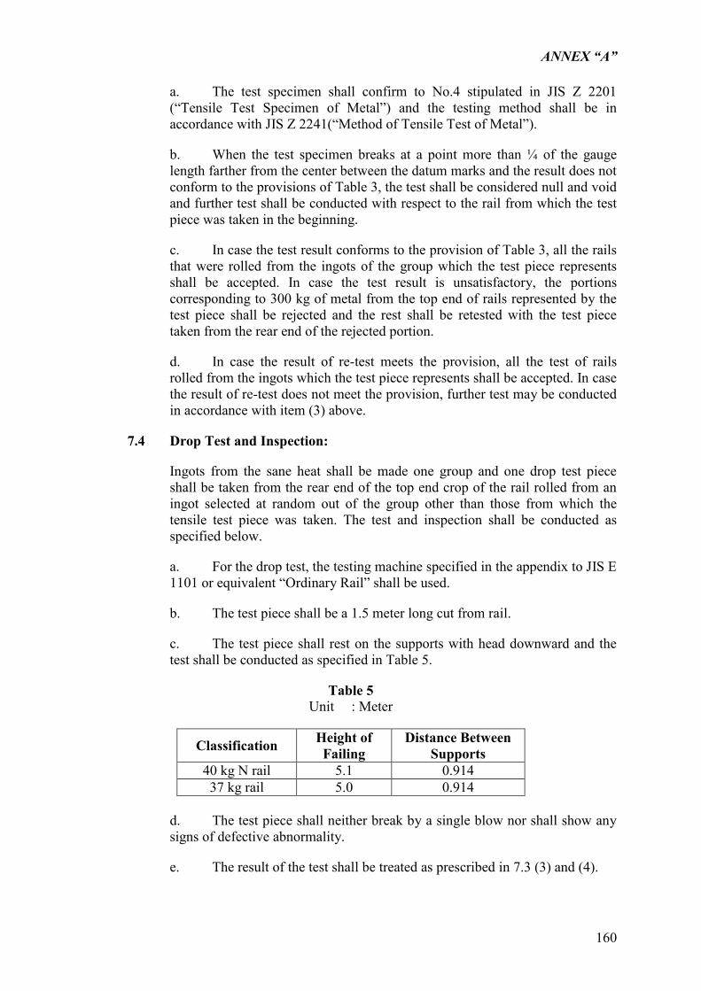
ANNEX “A”
160
a. The test specimen shall confirm to No.4 stipulated in JIS Z 2201 (“Tensile Test Specimen of Metal”) and the testing method shall be in accordance with JIS Z 2241(“Method of Tensile Test of Metal”).
b. When the test specimen breaks at a point more than ¼ of the gauge length farther from the center between the datum marks and the result does not conform to the provisions of Table 3, the test shall be considered null and void and further test shall be conducted with respect to the rail from which the test piece was taken in the beginning.
c. In case the test result conforms to the provision of Table 3, all the rails that were rolled from the ingots of the group which the test piece represents shall be accepted. In case the test result is unsatisfactory, the portions corresponding to 300 kg of metal from the top end of rails represented by the test piece shall be rejected and the rest shall be retested with the test piece taken from the rear end of the rejected portion.
d. In case the result of re-test meets the provision, all the test of rails rolled from the ingots which the test piece represents shall be accepted. In case the result of re-test does not meet the provision, further test may be conducted in accordance with item (3) above.
7.4 Drop Test and Inspection:
Ingots from the sane heat shall be made one group and one drop test piece shall be taken from the rear end of the top end crop of the rail rolled from an ingot selected at random out of the group other than those from which the tensile test piece was taken. The test and inspection shall be conducted as specified below.
a. For the drop test, the testing machine specified in the appendix to JIS E 1101 or equivalent “Ordinary Rail” shall be used.
b. The test piece shall be a 1.5 meter long cut from rail.
c. The test piece shall rest on the supports with head downward and the test shall be conducted as specified in Table 5.
Table 5 Unit : Meter
Classification Height of Failing
Distance Between Supports
40 kg N rail 5.1 0.914 37 kg rail 5.0 0.914
d. The test piece shall neither break by a single blow nor shall show any signs of defective abnormality.
e. The result of the test shall be treated as prescribed in 7.3 (3) and (4).
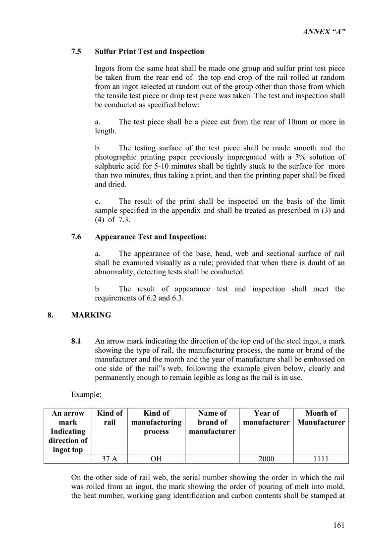
ANNEX “A”
161
7.5 Sulfur Print Test and Inspection
Ingots from the same heat shall be made one group and sulfur print test piece be taken from the rear end of the top end crop of the rail rolled at random from an ingot selected at random out of the group other than those from which the tensile test piece or drop test piece was taken. The test and inspection shall be conducted as specified below:
a. The test piece shall be a piece cut from the rear of 10mm or more in length.
b. The testing surface of the test piece shall be made smooth and the photographic printing paper previously impregnated with a 3% solution of sulphuric acid for 5-10 minutes shall be tightly stuck to the surface for more than two minutes, thus taking a print, and then the printing paper shall be fixed and dried.
c. The result of the print shall be inspected on the basis of the limit sample specified in the appendix and shall be treated as prescribed in (3) and (4) of 7.3.
7.6 Appearance Test and Inspection:
a. The appearance of the base, head, web and sectional surface of rail shall be examined visually as a rule; provided that when there is doubt of an abnormality, detecting tests shall be conducted.
b. The result of appearance test and inspection shall meet the requirements of 6.2 and 6.3.
8. MARKING
8.1 An arrow mark indicating the direction of the top end of the steel ingot, a mark
showing the type of rail, the manufacturing process, the name or brand of the manufacturer and the month and the year of manufacture shall be embossed on one side of the rail‟s web, following the example given below, clearly and permanently enough to remain legible as long as the rail is in use.
Example:
An arrow mark
Indicating direction of
ingot top
Kind of rail
Kind of manufacturing
process
Name of brand of
manufacturer
Year of manufacturer
Month of Manufacturer
37 A OH 2000 1111
On the other side of rail web, the serial number showing the order in which the rail was rolled from an ingot, the mark showing the order of pouring of melt into mold, the heat number, working gang identification and carbon contents shall be stamped at
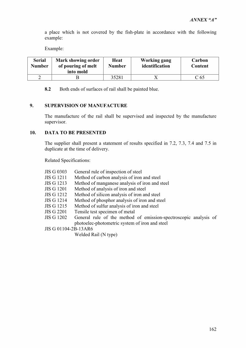
ANNEX “A”
162
a place which is not covered by the fish-plate in accordance with the following example:
Example:
Serial Number
Mark showing order of pouring of melt
into mold
Heat Number
Working gang identification
Carbon Content
2 B 35281 X C 65
8.2 Both ends of surfaces of rail shall be painted blue.
9. SUPERVISION OF MANUFACTURE
The manufacture of the rail shall be supervised and inspected by the manufacture supervisor.
10. DATA TO BE PRESENTED
The supplier shall present a statement of results specified in 7.2, 7.3, 7.4 and 7.5 in duplicate at the time of delivery. Related Specifications:
JIS G 0303 General rule of inspection of steel JIS G 1211 Method of carbon analysis of iron and steel JIS G 1213 Method of manganese analysis of iron and steel JIS G 1201 Method of analysis of iron and steel JIS G 1212 Method of silicon analysis of iron and steel JIS G 1214 Method of phosphor analysis of iron and steel JIS G 1215 Method of sulfur analysis of iron and steel JIS G 2201 Tensile test specimen of metal JIS G 1202 General rule of the method of emission-spectroscopic analysis of
photoelec-photometric system of iron and steel JIS G 01104-2B-13AR6
Welded Rail (N type)
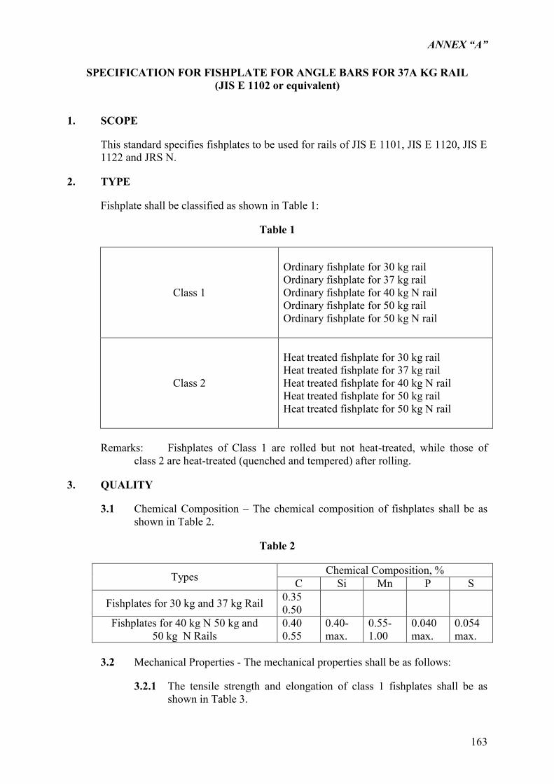
ANNEX “A”
163
SPECIFICATION FOR FISHPLATE FOR ANGLE BARS FOR 37A KG RAIL
(JIS E 1102 or equivalent)
1. SCOPE
This standard specifies fishplates to be used for rails of JIS E 1101, JIS E 1120, JIS E 1122 and JRS N.
2. TYPE
Fishplate shall be classified as shown in Table 1:
Table 1
Class 1
Ordinary fishplate for 30 kg rail Ordinary fishplate for 37 kg rail Ordinary fishplate for 40 kg N rail Ordinary fishplate for 50 kg rail Ordinary fishplate for 50 kg N rail
Class 2
Heat treated fishplate for 30 kg rail Heat treated fishplate for 37 kg rail Heat treated fishplate for 40 kg N rail Heat treated fishplate for 50 kg rail Heat treated fishplate for 50 kg N rail
Remarks: Fishplates of Class 1 are rolled but not heat-treated, while those of
class 2 are heat-treated (quenched and tempered) after rolling.
3. QUALITY
3.1 Chemical Composition – The chemical composition of fishplates shall be as shown in Table 2.
Table 2
Types Chemical Composition, % C Si Mn P S
Fishplates for 30 kg and 37 kg Rail 0.35 0.50
Fishplates for 40 kg N 50 kg and 50 kg N Rails
0.40 0.55
0.40-max.
0.55-1.00
0.040 max.
0.054 max.
3.2 Mechanical Properties - The mechanical properties shall be as follows:
3.2.1 The tensile strength and elongation of class 1 fishplates shall be as shown in Table 3.
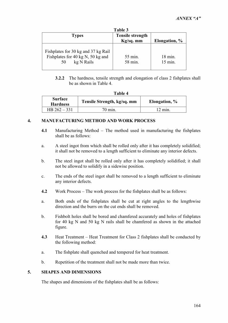
ANNEX “A”
164
Table 3 Types
Tensile strength
Kg/sq. mm
Elongation, %
Fishplates for 30 kg and 37 kg Rail Fishplates for 40 kg N, 50 kg and
50 kg N Rails
55 min. 58 min.
18 min. 15 min.
3.2.2 The hardness, tensile strength and elongation of class 2 fishplates shall
be as shown in Table 4.
Table 4 Surface
Hardness Tensile Strength, kg/sq. mm Elongation, %
HB 262 – 331 70 min. 12 min. 4. MANUFACTURING METHOD AND WORK PROCESS
4.1 Manufacturing Method – The method used in manufacturing the fishplates shall be as follows:
a. A steel ingot from which shall be rolled only after it has completely solidified; it shall not be removed to a length sufficient to eliminate any interior defects.
b. The steel ingot shall be rolled only after it has completely solidified; it shall not be allowed to solidify in a sidewise position.
c. The ends of the steel ingot shall be removed to a length sufficient to eliminate any interior defects.
4.2 Work Process – The work process for the fishplates shall be as follows:
a. Both ends of the fishplates shall be cut at right angles to the lengthwise direction and the burrs on the cut ends shall be removed.
b. Fishbolt holes shall be bored and chamfered accurately and holes of fishplates for 40 kg N and 50 kg N rails shall be chamfered as shown in the attached figure.
4.3 Heat Treatment – Heat Treatment for Class 2 fishplates shall be conducted by the following method:
a. The fishplate shall quenched and tempered for heat treatment.
b. Repetition of the treatment shall not be made more than twice.
5. SHAPES AND DIMENSIONS
The shapes and dimensions of the fishplates shall be as follows:
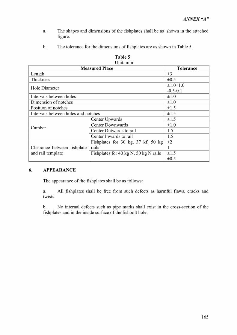
ANNEX “A”
165
a. The shapes and dimensions of the fishplates shall be as shown in the attached figure.
b. The tolerance for the dimensions of fishplates are as shown in Table 5.
Table 5 Unit. mm
Measured Place Tolerance Length ±3 Thickness ±0.5
Hole Diameter ±1.0+1.0 -0.5-0.1
Intervals between holes ±1.0 Dimension of notches ±1.0 Position of notches ±1.5 Intervals between holes and notches ±1.5
Camber
Center Upwards ±1.5 Center Downwards +1.0 Center Outwards to rail 1.5 Center Inwards to rail 1.5
Clearance between fishplate and rail template
Fishplates for 30 kg, 37 kf, 50 kg rails
±2 1
Fishplates for 40 kg N, 50 kg N rails ±1.5 ±0.5
6. APPEARANCE
The appearance of the fishplates shall be as follows:
a. All fishplates shall be free from such defects as harmful flaws, cracks and twists.
b. No internal defects such as pipe marks shall exist in the cross-section of the fishplates and in the inside surface of the fishbolt hole.
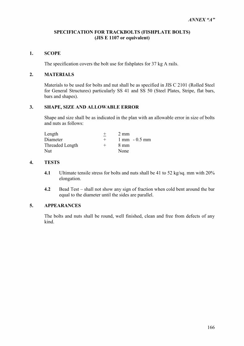
ANNEX “A”
166
SPECIFICATION FOR TRACKBOLTS (FISHPLATE BOLTS)
(JIS E 1107 or equivalent)
1. SCOPE
The specification covers the bolt use for fishplates for 37 kg A rails.
2. MATERIALS
Materials to be used for bolts and nut shall be as specified in JIS C 2101 (Rolled Steel for General Structures) particularly SS 41 and SS 50 (Steel Plates, Stripe, flat bars, bars and shapes).
3. SHAPE, SIZE AND ALLOWABLE ERROR
Shape and size shall be as indicated in the plan with an allowable error in size of bolts and nuts as follows:
Length + 2 mm Diameter + 1 mm - 0.5 mm Threaded Length + 8 mm Nut None
4. TESTS
4.1 Ultimate tensile stress for bolts and nuts shall be 41 to 52 kg/sq. mm with 20% elongation.
4.2 Bead Test – shall not show any sign of fraction when cold bent around the bar equal to the diameter until the sides are parallel.
5. APPEARANCES
The bolts and nuts shall be round, well finished, clean and free from defects of any kind.
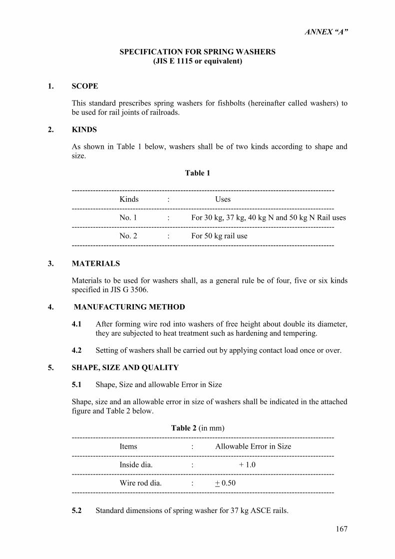
ANNEX “A”
167
SPECIFICATION FOR SPRING WASHERS
(JIS E 1115 or equivalent)
1. SCOPE
This standard prescribes spring washers for fishbolts (hereinafter called washers) to be used for rail joints of railroads.
2. KINDS
As shown in Table 1 below, washers shall be of two kinds according to shape and size.
Table 1
--------------------------------------------------------------------------------------------------- Kinds : Uses --------------------------------------------------------------------------------------------------- No. 1 : For 30 kg, 37 kg, 40 kg N and 50 kg N Rail uses --------------------------------------------------------------------------------------------------- No. 2 : For 50 kg rail use --------------------------------------------------------------------------------------------------- 3. MATERIALS
Materials to be used for washers shall, as a general rule be of four, five or six kinds specified in JIS G 3506.
4. MANUFACTURING METHOD
4.1 After forming wire rod into washers of free height about double its diameter, they are subjected to heat treatment such as hardening and tempering.
4.2 Setting of washers shall be carried out by applying contact load once or over.
5. SHAPE, SIZE AND QUALITY
5.1 Shape, Size and allowable Error in Size
Shape, size and an allowable error in size of washers shall be indicated in the attached figure and Table 2 below.
Table 2 (in mm) --------------------------------------------------------------------------------------------------- Items : Allowable Error in Size --------------------------------------------------------------------------------------------------- Inside dia. : + 1.0 --------------------------------------------------------------------------------------------------- Wire rod dia. : + 0.50 ---------------------------------------------------------------------------------------------------
5.2 Standard dimensions of spring washer for 37 kg ASCE rails.
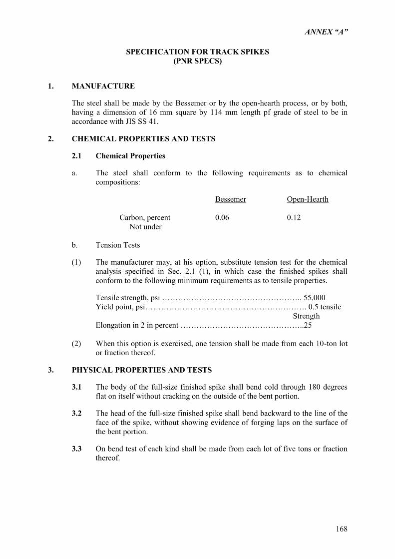
ANNEX “A”
168
SPECIFICATION FOR TRACK SPIKES
(PNR SPECS)
1. MANUFACTURE
The steel shall be made by the Bessemer or by the open-hearth process, or by both, having a dimension of 16 mm square by 114 mm length pf grade of steel to be in accordance with JIS SS 41.
2. CHEMICAL PROPERTIES AND TESTS
2.1 Chemical Properties
a. The steel shall conform to the following requirements as to chemical compositions:
Bessemer Open-Hearth
Carbon, percent 0.06 0.12 Not under
b. Tension Tests
(1) The manufacturer may, at his option, substitute tension test for the chemical analysis specified in Sec. 2.1 (1), in which case the finished spikes shall conform to the following minimum requirements as to tensile properties.
Tensile strength, psi …………………………………………….. 55,000 Yield point, psi……………………………………………………. 0.5 tensile Strength Elongation in 2 in percent ………………………………………..25 (2) When this option is exercised, one tension shall be made from each 10-ton lot
or fraction thereof.
3. PHYSICAL PROPERTIES AND TESTS
3.1 The body of the full-size finished spike shall bend cold through 180 degrees flat on itself without cracking on the outside of the bent portion.
3.2 The head of the full-size finished spike shall bend backward to the line of the face of the spike, without showing evidence of forging laps on the surface of the bent portion.
3.3 On bend test of each kind shall be made from each lot of five tons or fraction thereof.
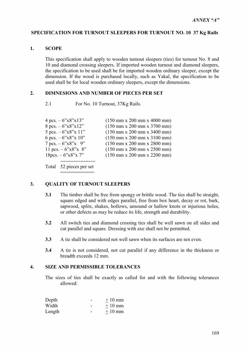
ANNEX “A”
169
SPECIFICATION FOR TURNOUT SLEEPERS FOR TURNOUT NO. 10 37 Kg Rails
1. SCOPE
This specification shall apply to wooden turnout sleepers (ties) for turnout No. 8 and 10 and diamond crossing sleepers. If imported wooden turnout and diamond sleepers, the specification to be used shall be for imported wooden ordinary sleeper, except the dimension. If the wood is purchased locally, such as Yakal, the specification to be used shall be for local wooden ordinary sleepers, except the dimensions.
2. DIMNESIONS AND NUMBER OF PIECES PER SET
2.1 For No. 10 Turnout, 37Kg Rails.
4 pcs. – 6”x8”x13‟ (150 mm x 200 mm x 4000 mm) 8 pcs. – 6”x8”x12‟ (150 mm x 200 mm x 3700 mm) 5 pcs. – 6”x8”x 11‟ (150 mm x 200 mm x 3400 mm) 6 pcs. – 6”x8”x 10‟ (150 mm x 200 mm x 3100 mm) 7 pcs. – 6”x8”x 9‟ (150 mm x 200 mm x 2800 mm) 11 pcs. – 6”x8”x 8‟ (150 mm x 200 mm x 2500 mm) 18pcs. – 6”x8”x 7‟ (150 mm x 200 mm x 2200 mm)
--------------------- Total 52 pieces per set
============
3. QUALITY OF TURNOUT SLEEPERS
3.1 The timber shall be free from spongy or brittle wood. The ties shall be straight, square edged and with edges parallel, free from box heart, decay or rot, bark, sapwood, splits, shakes, hollows, unsound or hallow knots or injurious holes, or other defects as may be reduce its life, strength and durability.
3.2 All switch ties and diamond crossing ties shall be well sawn on all sides and cut parallel and square. Dressing with axe shall not be permitted.
3.3 A tie shall be considered not well sawn when its surfaces are not even.
3.4 A tie is not considered, not cut parallel if any difference in the thickness or breadth exceeds 12 mm.
4. SIZE AND PERMISSIBLE TOLERANCES
The sizes of ties shall be exactly as called for and with the following tolerances allowed:
Depth - + 10 mm Width - + 10 mm Length - + 10 mm
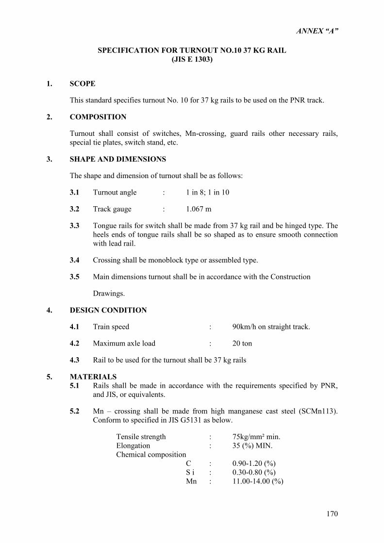
ANNEX “A”
170
SPECIFICATION FOR TURNOUT NO.10 37 KG RAIL
(JIS E 1303)
1. SCOPE
This standard specifies turnout No. 10 for 37 kg rails to be used on the PNR track.
2. COMPOSITION
Turnout shall consist of switches, Mn-crossing, guard rails other necessary rails, special tie plates, switch stand, etc.
3. SHAPE AND DIMENSIONS
The shape and dimension of turnout shall be as follows:
3.1 Turnout angle : 1 in 8; 1 in 10
3.2 Track gauge : 1.067 m
3.3 Tongue rails for switch shall be made from 37 kg rail and be hinged type. The heels ends of tongue rails shall be so shaped as to ensure smooth connection with lead rail.
3.4 Crossing shall be monoblock type or assembled type.
3.5 Main dimensions turnout shall be in accordance with the Construction
Drawings.
4. DESIGN CONDITION
4.1 Train speed : 90km/h on straight track.
4.2 Maximum axle load : 20 ton
4.3 Rail to be used for the turnout shall be 37 kg rails
5. MATERIALS 5.1 Rails shall be made in accordance with the requirements specified by PNR,
and JIS, or equivalents.
5.2 Mn – crossing shall be made from high manganese cast steel (SCMn113). Conform to specified in JIS G5131 as below.
Tensile strength : 75kg/mm² min. Elongation : 35 (%) MIN. Chemical composition C : 0.90-1.20 (%) S i : 0.30-0.80 (%) Mn : 11.00-14.00 (%)
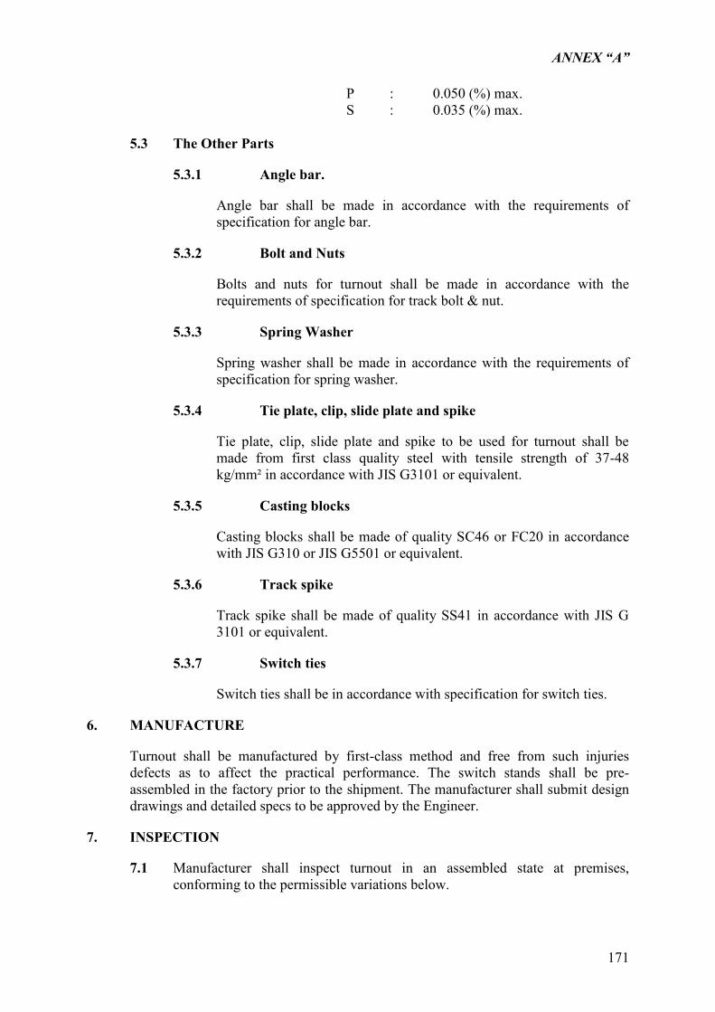
ANNEX “A”
171
P : 0.050 (%) max. S : 0.035 (%) max.
5.3 The Other Parts
5.3.1 Angle bar.
Angle bar shall be made in accordance with the requirements of specification for angle bar.
5.3.2 Bolt and Nuts
Bolts and nuts for turnout shall be made in accordance with the requirements of specification for track bolt & nut.
5.3.3 Spring Washer
Spring washer shall be made in accordance with the requirements of specification for spring washer.
5.3.4 Tie plate, clip, slide plate and spike
Tie plate, clip, slide plate and spike to be used for turnout shall be made from first class quality steel with tensile strength of 37-48 kg/mm² in accordance with JIS G3101 or equivalent.
5.3.5 Casting blocks
Casting blocks shall be made of quality SC46 or FC20 in accordance with JIS G310 or JIS G5501 or equivalent.
5.3.6 Track spike
Track spike shall be made of quality SS41 in accordance with JIS G 3101 or equivalent.
5.3.7 Switch ties
Switch ties shall be in accordance with specification for switch ties.
6. MANUFACTURE
Turnout shall be manufactured by first-class method and free from such injuries defects as to affect the practical performance. The switch stands shall be pre-assembled in the factory prior to the shipment. The manufacturer shall submit design drawings and detailed specs to be approved by the Engineer.
7. INSPECTION
7.1 Manufacturer shall inspect turnout in an assembled state at premises, conforming to the permissible variations below.
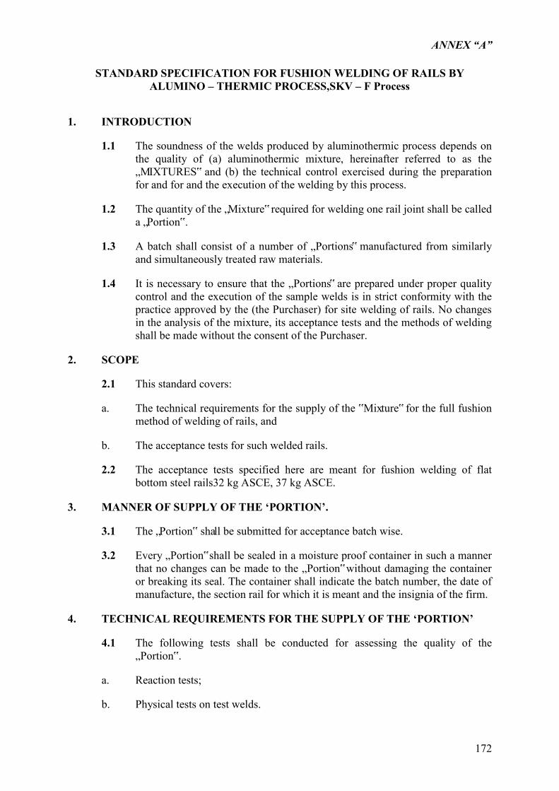
ANNEX “A”
172
STANDARD SPECIFICATION FOR FUSHION WELDING OF RAILS BY
ALUMINO – THERMIC PROCESS,SKV – F Process
1. INTRODUCTION
1.1 The soundness of the welds produced by aluminothermic process depends on the quality of (a) aluminothermic mixture, hereinafter referred to as the „MIXTURES‟ and (b) the technical control exercised during the preparation for and for and the execution of the welding by this process.
1.2 The quantity of the „Mixture‟ required for welding one rail joint shall be called a „Portion‟.
1.3 A batch shall consist of a number of „Portions‟ manufactured from similarly and simultaneously treated raw materials.
1.4 It is necessary to ensure that the „Portions‟ are prepared under proper quality control and the execution of the sample welds is in strict conformity with the practice approved by the (the Purchaser) for site welding of rails. No changes in the analysis of the mixture, its acceptance tests and the methods of welding shall be made without the consent of the Purchaser.
2. SCOPE
2.1 This standard covers:
a. The technical requirements for the supply of the ‟Mixture‟ for the full fushion method of welding of rails, and
b. The acceptance tests for such welded rails.
2.2 The acceptance tests specified here are meant for fushion welding of flat bottom steel rails32 kg ASCE, 37 kg ASCE.
3. MANNER OF SUPPLY OF THE ‘PORTION’.
3.1 The „Portion‟ shall be submitted for acceptance batch wise.
3.2 Every „Portion‟ shall be sealed in a moisture proof container in such a manner that no changes can be made to the „Portion‟ without damaging the container or breaking its seal. The container shall indicate the batch number, the date of manufacture, the section rail for which it is meant and the insignia of the firm.
4. TECHNICAL REQUIREMENTS FOR THE SUPPLY OF THE ‘PORTION’
4.1 The following tests shall be conducted for assessing the quality of the „Portion‟.
a. Reaction tests;
b. Physical tests on test welds.
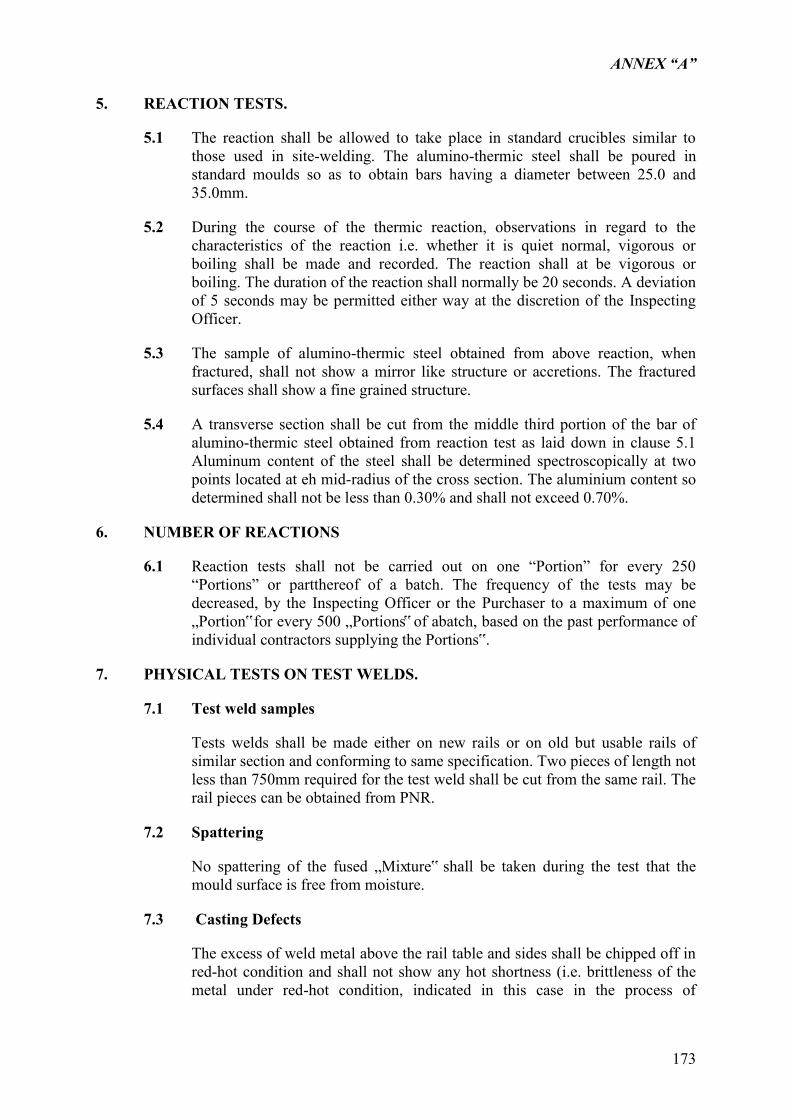
ANNEX “A”
173
5. REACTION TESTS.
5.1 The reaction shall be allowed to take place in standard crucibles similar to those used in site-welding. The alumino-thermic steel shall be poured in standard moulds so as to obtain bars having a diameter between 25.0 and 35.0mm.
5.2 During the course of the thermic reaction, observations in regard to the characteristics of the reaction i.e. whether it is quiet normal, vigorous or boiling shall be made and recorded. The reaction shall at be vigorous or boiling. The duration of the reaction shall normally be 20 seconds. A deviation of 5 seconds may be permitted either way at the discretion of the Inspecting Officer.
5.3 The sample of alumino-thermic steel obtained from above reaction, when fractured, shall not show a mirror like structure or accretions. The fractured surfaces shall show a fine grained structure.
5.4 A transverse section shall be cut from the middle third portion of the bar of alumino-thermic steel obtained from reaction test as laid down in clause 5.1 Aluminum content of the steel shall be determined spectroscopically at two points located at eh mid-radius of the cross section. The aluminium content so determined shall not be less than 0.30% and shall not exceed 0.70%.
6. NUMBER OF REACTIONS
6.1 Reaction tests shall not be carried out on one “Portion” for every 250 “Portions” or partthereof of a batch. The frequency of the tests may be decreased, by the Inspecting Officer or the Purchaser to a maximum of one „Portion‟ for every 500 „Portions‟ of abatch, based on the past performance of individual contractors supplying the Portions‟.
7. PHYSICAL TESTS ON TEST WELDS.
7.1 Test weld samples
Tests welds shall be made either on new rails or on old but usable rails of similar section and conforming to same specification. Two pieces of length not less than 750mm required for the test weld shall be cut from the same rail. The rail pieces can be obtained from PNR.
7.2 Spattering
No spattering of the fused „Mixture‟ shall be taken during the test that the mould surface is free from moisture.
7.3 Casting Defects
The excess of weld metal above the rail table and sides shall be chipped off in red-hot condition and shall not show any hot shortness (i.e. brittleness of the metal under red-hot condition, indicated in this case in the process of
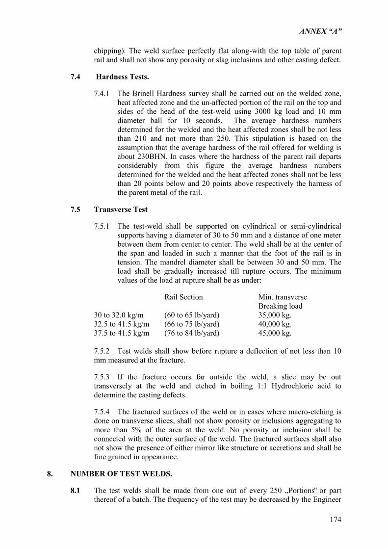
ANNEX “A”
174
chipping). The weld surface perfectly flat along-with the top table of parent rail and shall not show any porosity or slag inclusions and other casting defect.
7.4 Hardness Tests.
7.4.1 The Brinell Hardness survey shall be carried out on the welded zone, heat affected zone and the un-affected portion of the rail on the top and sides of the head of the test-weld using 3000 kg load and 10 mm diameter ball for 10 seconds. The average hardness numbers determined for the welded and the heat affected zones shall be not less than 210 and not more than 250. This stipulation is based on the assumption that the average hardness of the rail offered for welding is about 230BHN. In cases where the hardness of the parent rail departs considerably from this figure the average hardness numbers determined for the welded and the heat affected zones shall not be less than 20 points below and 20 points above respectively the harness of the parent metal of the rail.
7.5 Transverse Test
7.5.1 The test-weld shall be supported on cylindrical or semi-cylindrical supports having a diameter of 30 to 50 mm and a distance of one meter between them from center to center. The weld shall be at the center of the span and loaded in such a manner that the foot of the rail is in tension. The mandrel diameter shall be between 30 and 50 mm. The load shall be gradually increased till rupture occurs. The minimum values of the load at rupture shall be as under:
Rail Section Min. transverse Breaking load
30 to 32.0 kg/m (60 to 65 lb/yard) 35,000 kg. 32.5 to 41.5 kg/m (66 to 75 lb/yard) 40,000 kg. 37.5 to 41.5 kg/m (76 to 84 lb/yard) 45,000 kg. 7.5.2 Test welds shall show before rupture a deflection of not less than 10 mm measured at the fracture.
7.5.3 If the fracture occurs far outside the weld, a slice may be out transversely at the weld and etched in boiling 1:1 Hydrochloric acid to determine the casting defects.
7.5.4 The fractured surfaces of the weld or in cases where macro-etching is done on transverse slices, shall not show porosity or inclusions aggregating to more than 5% of the area at the weld. No porosity or inclusion shall be connected with the outer surface of the weld. The fractured surfaces shall also not show the presence of either mirror like structure or accretions and shall be fine grained in appearance.
8. NUMBER OF TEST WELDS.
8.1 The test welds shall be made from one out of every 250 „Portions‟ or part thereof of a batch. The frequency of the test may be decreased by the Engineer
ANNEX “A”
175
or the Purchaser to a maximum of one every 500 „Portions‟ of a batch, based on the past performance of individual contractors supplying the “Portions‟.
9. RETESTS
9.1 Should the results of any of the tests referred to in Clauses 5 to 7 be unsatisfactory and should the Supplier forth-with give notice in the writing to the Engineer or the Purchaser that he desires additional tests to be carried out, these shall be carried out at his own expense. These additional tests shall be carried out in the same manner in all respects as the tests originally carried out on another two „Portions‟ from the same batch selected by the Inspecting Officer or the Purchaser.
9.2 If the results of both these tests are satisfactory, the batch represented by the „Portion‟ from which these welds were prepared may be accepted. If either or both the tests show any of the above defects, the batch shall be rejected.
10. ADDITIONAL TESTSAFTER REPROCESSING.
10.1 In the event of any sample „Portion‟ from a batch failing to comply with the requirement ofClause 5.4 the supplier, if he desired so, may be permitted to resubmit the batch after necessary reprocessing once only. The reprocessed „Portions‟ shall be resubmitted under a separate batch and serial numbers.
11. ACCEPTANCE
11.1 Acceptance shall be done batch wise. Every individual batch that satisfies the conditions prescribed in the specification shall be accepted after an identification mark has been put on it by the Inspecting Officer.
12. TESTING FACILITIES.
12.1 The supplier shall at his own expense supply all labor and appliances for such testing as may be carried out in the presence of the purchaser or the Engineer in his own premises or at any other pace acceptable to the Purchaser in accordance with this Specification.
13. ACCEPTANCE TESTS FOR WELDED JOINTS
13.1 Fusion welding of rails by this process shall be executed in accordance with the best practice approved by the Purchaser. Only approved „Portions‟ shall be used for the work.
13.2 Rail joints welded by a supplier shall be guaranteed by him against failure for a period of two years from the date of making the welds or from the date such welded joints are inserted in the track, in case the welding is done outside the track. Any such welded joint, which fails by cracking within this period of guarantee, shall be re-welded free of cost by the supplier.
13.3 One out of every 100 welded joints shall be picked up at random and subjected to hardness and transverse tests as laid down in Clauses 7.4 and 7.5 shall comply with the provisions laid therein.
ANNEX “A”
176
13.3.1 In the event of any welded joint failing in any one or more requirements of this specification, the Railways will be at liberty to suspend forthwith further welding of joints. The work will remain suspended until the supplier has improved his welding technique and the Joints welded by him can stand up to the above tests. Further, the period of guarantee vide Clause 13.2 above of the Joint already welded shall be extend for a further period of one year and any such welded joint which fails within this extended period of guarantee or shows signs of failure by cracking shall be re-welded free of cost by the supplier.
13.3.2 The welded joints with the extended period of guarantee shall be marked „X‟ on the outer side of the head of the rail near the Joint in addition to the markings prescribed in Clause 14. Such marked joints shall be kept under careful observation by the Railway.
14. MARKINGS
14.1 All the welded Joint shall be distinctly stamped by the supplier in the following manner:
(Month, Year, firm‟s insignia) and „X‟ (where necessary).
The markings shall be on the outer side of the rail head within 150 mm from the welded joints.
ANNEX “A”
177
SPECIFICATIONS FOR WOODEN JOINT TIES
1.1 SCOPE
This specification covers the requirement for size, shape, quality, physical properties, inspection, testing, marking and acceptance of joint wood sleepers from acceptable species.
1.2 GENERAL
All ties shall be cut from mature, healthy live trees and shall be of the following species:
I. LOCAL WOOD a. Basilan – Yakal (H. Basilanica Foxw.) b. Yakal – Kaliot (H. Malibato Foxw.) c. Yakal – Magasusu (H. Mindanensis Foxw.) d. Yakal – Saplungan (H. Plagata (Bico) Vid) e. Yakal – (S. Astylosa Foxw.) f. Yakal – Gisok (S. Gisok Foxw.) g. Yakal – Mabolo (S. Ciliata King) h. Yakal – Malibato (S. Malibato Foxw.) i. Yakal – Yambak (S. Faloefereides Foxw.) II. IMPORTED WOOD
All imported timbers are to be merbau, yellow be merbau, yellow Balau, Selangan Batu No. 1 or Chengal or equivalent imported hard wood that will comply with the ranges of the mechanical and related properties of Philippine woods as stated in the tabulation in this Technical Specifications.
a. SELANGAN BATU TIMBER SLEEPER
RANGE: 45 species in Shorea group of this genus from Ceylon and India to Malaya, Borneo, the Philippines and Moluccas. Sul (S. robusta) in Indian, Guijo (S. guiso) in Philippine and Bangkirai (Shorea sp. Including S. laevis) in Borneo best known in this group.
Large amount imported to Japan from Sabah and Sarawak mixed with Meranti. Logs quite similar to Meranti and careful classification needed.
PROPERTIES: Wood very hard, which distinguishes Seraya.
BARK: Similar to Seraya. Usually fibrous inner bark left on logs when imported.
WOOD: Yellow, yellow brown or red brown and some greenish on surface. Heartwood somewhat distinct and sapwood paler.
WEIGHT: A.D.0.84 ~ 1.05.
GRAIN: Interlocked.
ANNEX “A”
178
TEXTURE: Moderately fine or fine.
1.2.1 The timber shall be free from spongy or brittle wood. Except, as otherwise permitted in this specification, sleepers shall be straight, square edged, and with edges parallel, free from boxed heart, decay or rot, bark, sapwood, splits, shakes, hollows, unsound or hollow knots or injurious holes, scars or any other defects as may reduce its life, strength and durability.
1.2.2 All sleepers shall be well sawn on all sides and cut parallel and square. Dressing with axe shall not be permitted.
1.2.2.1 A Sleeper shall be considered not cut parallel if any difference in the thickness and breadth exceeds 12 mm.
1.2.2.2 A sleeper is considered not cut parallel if any difference in the thickness and breadth exceeds 12 mm.
1.2.2.3 If the sleeper is longer than specified, it should be reduced to the proper length before it is offered for inspection.
1.3 PERMISSIBILITY OF DEFECTS
1.3.1
Center or Boxed Heart of Presence of Pith will not be permitted. Sleepers with center or boxed heart may, however, be accepted but only on molave species if the heart is sound and tight.
1.3.2 Cracks and Splits
(1) End Splits – Provided a split does not seem likely to extend and is not in the direction of the spike position and the sleeper is not freshly sawn, a sleeper with this defect may be accepted if the split does not exceed 150 mm in length and not more than 1.5 mm in width.
(2) Cross Breaks – Sleepers with cross breaks are not acceptable.
(3) Surface Cracks – Sleepers sawn from sound timber with this defect may be accepted provided the cracks are light.
(4) Sun or Seasoning Cracks – This is not easy to define. It may be taken to mean a sleeper which is in existence for at least three months from the date of conversion from the log. The color of freshly sawn sleepers is usually white and this provides an indication of probable age. In deciding the age of sleeper, inspecting officers can take other factors into account such as the time taken to reach the railway depot, period held in storage at depot from local inquiry, etc. These would be permitted if they are light.
(5) Miscellaneous Cracks and Splits – Ordinary cracks and splits may be permitted if they are light.
ANNEX “A”
179
1.3.3 Crook, Cup, Twist and Bow
(1) Crook – This will be permitted with a maximum deviation of 70 mm. An S – bend on the width of the sleeper and bend on the depth is not acceptable.
(2) Cup, twist and bow are not acceptable.
1.3.4 Decay
Sleepers containing decay or rot in any form of degree will not be accepted.
1.3.5 Heart Defects – Sleepers with deep heart crack and winding heart crack are not acceptable.
1.3.6 Hollows, Knots, and Scars
(1) Hollows – Hollows not more than 12 mm in diameter and less than 25 mm deep and not exceeding three hollows per 300 mm length of the sleeper may be permissible. No hollow shall be permitted between 450 mm and 750 mm from the center of the sleeper.
(2) Knots – No sleeper will be accepted with large knots within the section lying between 450 mm and 750 mm from the center of its length. Large knots are those with diameter exceeding one – half of the width of the surface on which it appears. No loose, hollow or unsound knots shall be permitted.
(3) Scars – Any small scar away from the rail seat will be permissible.
(4) Sleepers with ruptured ends will not be accepted.
1.3.7 Sapwood
Presence of sapwood is permissible along one narrow surface of the sleepers only but shall not exceed 12 mm thick. Sapwood is not permissible in general on undersize sleepers.
1.3.8 Shakes
(1) Cup Shakes – These will not be permitted under the rail seat. Elsewhere it may be permitted if less than 50 mm in width and not more than 300 mm from the end of the sleeper.
1.4 SIZE
a. The standard joint sleeper dimensions are 5” x 10” x 7‟.
1.5 DELIVERY, INSPECTION, MARKING AND ACCEPTANCE
1.5.1
Sleepers shall be delivered and supplied at PNR station yard to be designated by the Engineer.
ANNEX “A”
180
1.5.2
The inspection of all sleepers will be made by the Engineer‟s Inspection Team and those that conform to this specification and accepted shall be branded/stamped by the Inspectors.
1.5.3
All sleepers offered for inspection must bear the Contractor‟s property mark, a facsimile of which should be furnished to the Engineer who may direct the Contractor to change it if considered not necessary. This facsimile shall be sleeper for identity of the Supplier/Contractor.
All sleepers intended for inspection shall be spread with their heart side up in long lines parallel with one another and supported with at least one support. Sleepers spread on the ground will not be inspected.
All sleepers must be cleaned of mud and dirt before inspection. The ends must be plastered at the time of inspection. Previously rejected sleepers should not be spread for inspection without prior advice unless they are the subject of a complaint to a higher authority in which case it will have the rejection mark of the Engineer‟s inspection Team who originally rejected them.
Sleepers of a longer length than actually required should first be cut to desired length before final/stamped accordingly by the Engineer‟s inspection Team unless sleeper is thus cut.
Sleepers will be inspected one by one, each sleeper being turned round for inspection, all sides and ends receiving individual inspection.
Contractor shall furnish all necessary labor to turn over all sleepers one by one for inspection and branding/tamping by the Engineer‟s inspection Team. All accepted sleepers will be stamped with big marking hammer at the middle top and clear faces of the sleepers. Accepted sleepers shall be completely marked with the following:
(1) “M” if Molave, “Y” if Yacal and first letter for named of imported wood.
(2) “L” to indicate properly inspected by representative of General Services Division
(3) “A” to indicate properly inspected by representative of Management Audits of PNR.
(4) “F” to indicate properly inspected by the representative of the Engineer.
All accepted sleepers after being completely marked shall immediately be stockpiled again in the same required manner.
All cost due to branding/marking of the sleeper by the Contractor/Supplier, spreading the sleepers for inspection and stockpiling them and loading on PNR boxcars shall be at the expense of the Contractor.
ANNEX “A”
181
1.5.4 FACILITIES FOR PRE-INSPECTION
The Contractor shall afford at his own expense all reasonable facilities to satisfy the Engineer‟s Inspection Team that the sleepers are in accordance with these specifications.
1.5.5 HANDLING OF JOINT SLEEPERS
Preservative treatment of Wooden Sleepers
(1) Any fabricating such as end trimming and, if required, adzing and boring or application of anti – cracking devices shall be performed at manufacturing plants of wood sleepers.
1.5.6 UNLOADING AND STACKING OF JOINT SLEEPERS
Wooden sleepers shall not be unloaded by dropping or throwing them onto rails, rock or hard surfaces. Sleepers shall be handled with tongs and not with bars or sharp tools to avoid any damage.
The Contractor shall fully coordinate with the Engineer and obtain his approval on locations, methods and times of storage of the wooden sleepers.
Stacks of sleepers shall be appropriately supported and likewise protected from sparks or other fire hazards and undue damage.
1.5.7 MECHANICAL AND RELATED PROPERTIES
When tested, imported hard wood shall meet the minimum ranges of Mechanical and Related Properties of Philippine Woods shown on Figure 1 .
ANNEX “A”
182
PART 8 DPWH STANDARDS FOR ASPHALT PAVEMENT OVERLAY AND PAVEMENT
MARKINGS
ITEM 306 – BITUMINOUS ROAD MIX SURFACE COURSE
306.1 Description
This Item shall consist of constructing a bituminous road-mix surface course on a prepared base in accordance with these Specification and in conformity with the lines, grades and typical cross-sections shown on the Plans, or as established by the Engineer.
306.2 Material Requirements
306.2.1 Bituminous Material
The bituminous material shall be either rapid Curing (RC) Cut-back, Medium Curing (MC) Cut-back or Emulsified Asphalt, whichever is called for in the Bill of Quantities. It shall conform to the requirements of Item 702, Bituminous Material. The type and grade will be specified in the Special Provisions.
306.2.2 Aggregate
The aggregate shall conform to applicable requirements of Item 703, Aggregates. It will be tested for acceptance immediately preceding addition of bituminous material to the mix. This Acceptance will be based on periodic samples from the windrowed materials after all aggregates have been blended for each layer.
The aggregate may be new or salvaged from the existing surface.
1. New Aggregate
It shall conform to the applicable requirements of Item 703, Aggregates.
2. Salvaged Aggregate
Where aggregate required for the road mix surface course is already in place, the Contractor shall not be responsible for its grading or quality except for removal of oversize pieces. In general, salvaged aggregate to be used for road mix surface course will consist of materials meeting the requirements given in Item 703, Aggregates, for new aggregate or may consist of selected granular material for other grading. Any particles of salvaged aggregate appearing in the surface at the time of lay-down and finishing that will not pass 37.5 mm (1-1/2 inch) sieve shall be removed by the Contractor as directed by the Engineer.
ANNEX “A”
183
306.2.3 Proportioning of Mixture
The proportion of bituminous material on the basis of total dry aggregate, shall be from 4.5 to 7.0 mass percent when cut-back asphalt is used and from 6.0 to 10.0 mass percent when emulsified asphalt is used. The exact percentage to be used shall be fixed by the Engineer in accordance with the job-mix formula and the other quality control requirements.
During the mixing operation, one-half to one (0.5 to 1.0) mass percent of hydrated lime, dry aggregate basis, shall be added to the mixture. The lower percentage limit is applicable to aggregates which are predominantly calcareous.
306.3 Construction Requirements
306.3.1 Weather Limitations
The construction of road mix bituminous pavement shall be carried on only when the surface on which the material is to be placed is dry and when the weather is not foggy or rainy.
306.3.2 Construction Equipment
The equipment used by the Contractor shall include scarifying, mixing, spreading, finishing and compacting equipment; a bituminous distributor; and the equipment for heating bituminous material.
The distributor shall be so designed, equipped, maintained and operated that bituminous material at even heat may be applied uniformly on variable widths of surface up to 4.5 m at readily determined and controlled rates from 0.2 to 10 L/m2, with uniform pressure, and with an allowable variation from any specified rate not to exceed 0.1 L/m2. Distributor equipment shall include a tachometer pressure gauge, accurate volume measuring devices or a calibrated tank, and a thermometer for measuring temperatures of tank contents. Distributors shall be equipped with a power unit for the pump, and full circulation spray bars adjustable laterally and vertically.
Travelling or stationary mixing plants or other equipment of proven performance may be used by the Contractor in lieu of the specified equipment, if approved by the Engineer.
Rollers shall be self-propelled steel-wheel tandem or 3-wheel rollers weighing not less than 8 tonnes each and pneumatic tire rollers having a total compacting width of not less than 1,520 mm (60 inches) and the gross mass adjustable within the range of 3,640 to 6,360 kilograms per metre (200 t0 350 pounds per inch) of compaction width. The operating mass shall be directed. Tire pressure or contact pressure may be specified for pneumatic-tire rollers. All tires on pneumatic rollers shall be equally inflated, exerting equal unit pressure, with a means of varying the contact pressure to suit project conditions.
ANNEX “A”
184
306.3.3 Preparation of Base
1. Case 1 (New Aggregate)
When new aggregate is to be used for the road mix surface course, the existing base shall be scarified lightly and bladed to uniform grade and to the cross-section shown on the Plans and shall then be rolled or watered and rolled, as directed. If so ordered by the Engineer, depressions shall first be filled and weak portions of the base strengthened with new aggregate.
2. Case 2 (Salvaged Aggregate)
When material in the existing road surface is to be used for mixing, the surface shall be scarified lightly and bladed to uniform grade and to the cross-section shown on the Plans. The reshaped surface shall then be scarified again to the depth ordered by the Engineer and in such manner as to leave a foundation of undisturbed material parallel, both in profile and cross-section, to the proposed finished surface. The loosened materials shall be bladed aside into a windrow at the side of the road and the undisturbed material rolled or watered and rolled, as directed.
306.3.4 Placing Aggregates
New aggregates, where required, shall be uniformly spread on the prepared surface by the use of spreader boxes, or other approved mechanical spreading devices. When two or more sizes of aggregates are used, each size of aggregate shall be placed in the proper amount to provide for surfacing of the required width and thickness. The proper amounts of the separate sizes of aggregate for each course shall be blended and shaped into a windrow of uniform cross-section. At least one day shall be allowed for measuring, sampling and testing for approval of quantity and gradation before the windrowed material is spread for application of bituminous material.
If the surface moisture of the aggregate is more than 2 percent of the dry weight of the aggregate, except when the bituminous material is emulsified asphalt, the aggregate shall be turned by blades or disc harrows or otherwise aerated until the moisture content is reduced to 2 percent or less. The aggregate shall then be spread smoothly and uniformly over half the road or other convenient width of the surface ready for the application of bituminous material, except that when a traveling mixing plant is used, the aggregate shall be formed into a uniform cross-section.
In lieu of aerating and drying the aggregate, the Contractor may use an approved additive, except where emulsified asphalt is used, which shall be satisfactorily blended with the bituminous material. The additive shall permit suitable coating of the wet aggregate and shall prevent the bituminous coating from stripping in the presence of water.
306.3.5 Application of Bituminous Material
The bituminous material shall be uniformly distributed in successive application, in such amounts and at such intervals as directed. The mixing
ANNEX “A”
185
equipment shall follow immediately behind the distributor, after each application of bituminous material, to partially mix the aggregate and the bituminous material.
306.3.6 Mixing
After the last application of bituminous material and partial mixing, the entire mass of bituminous material and aggregate shall be windrowed on the road surface and then mixed, by blading the mixture from side to side of the road, or by manipulation producing equivalent results, until all aggregate particles are coated with bituminous material and the whole mass has a uniform color and the mixture is free from fat or lean spots, or balls of uncoated particles. During the mixing operations, care shall be taken to avoid cutting into the underlying course or contaminating the mixture with earth or other extraneous matter. When directed, the mixing process shall be confined to part of the width or area of the road so as to allow traffic to pass.
Should the mixture show an excess, deficiency or uneven distribution of bituminous material, the condition shall be corrected by the addition of aggregate or bituminous material as required and re-mixing. If the mixture contains excessive amounts of moisture or volatile matter, it shall be bladed, aerated or otherwise manipulated until the moisture and volatile content are satisfactory. The spreading of the mix shall not be done when the surface to be covered is in an unsatisfactory condition. At the end of each day‟s work, or when the work is interrupted by weather conditions or otherwise, all loose materials shall be bladed into a windrow, whether mixing is completed or not, and shall be retained in a windrow until operations are resumed.
When the mixing operations have been satisfactorily completed, the mixture shall be formed into a windrow of uniform cross-section.
If the Contractor elects to use traveling or stationary mixing plants in lieu of the specified equipment, the same requirements regarding residual moisture and evaporation of volatiles given above shall apply.
306.3.7 Spreading, Compacting and Finishing
The material shall be spread by a self-propelled pneumatic-tire blade grader or a mechanical spreader of approved type. In spreading from the windrow, care shall be taken to avoid cutting into the underlying base.
After the material is spread, the surface shall be rolled. Rolling shall be parallel to the road center line and shall commence at the outer edges of the road, overlapping the shoulders and progressing towards the center, overlapping on successive passes by at least one-half the width of the roller, except that on superelevated curves, rolling shall progress from the lower to the upper edge.
Each pass shall terminate at least 910 mm (3 ft) in advance or to the rear of the end of the preceding pass. During compaction, the surface shall be dragged or bladed as necessary to fill ruts and to remove incipient corrugations or other irregularities. Rolling shall continue until the surfacing is of uniform texture
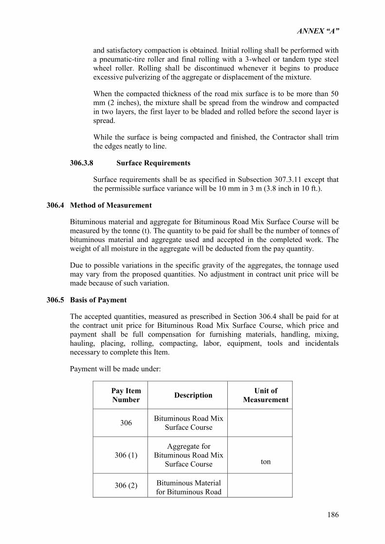
ANNEX “A”
186
and satisfactory compaction is obtained. Initial rolling shall be performed with a pneumatic-tire roller and final rolling with a 3-wheel or tandem type steel wheel roller. Rolling shall be discontinued whenever it begins to produce excessive pulverizing of the aggregate or displacement of the mixture.
When the compacted thickness of the road mix surface is to be more than 50 mm (2 inches), the mixture shall be spread from the windrow and compacted in two layers, the first layer to be bladed and rolled before the second layer is spread.
While the surface is being compacted and finished, the Contractor shall trim the edges neatly to line.
306.3.8 Surface Requirements
Surface requirements shall be as specified in Subsection 307.3.11 except that the permissible surface variance will be 10 mm in 3 m (3.8 inch in 10 ft.).
306.4 Method of Measurement
Bituminous material and aggregate for Bituminous Road Mix Surface Course will be measured by the tonne (t). The quantity to be paid for shall be the number of tonnes of bituminous material and aggregate used and accepted in the completed work. The weight of all moisture in the aggregate will be deducted from the pay quantity.
Due to possible variations in the specific gravity of the aggregates, the tonnage used may vary from the proposed quantities. No adjustment in contract unit price will be made because of such variation.
306.5 Basis of Payment
The accepted quantities, measured as prescribed in Section 306.4 shall be paid for at the contract unit price for Bituminous Road Mix Surface Course, which price and payment shall be full compensation for furnishing materials, handling, mixing, hauling, placing, rolling, compacting, labor, equipment, tools and incidentals necessary to complete this Item.
Payment will be made under:
Pay Item Number Description Unit of
Measurement
306 Bituminous Road Mix Surface Course
306 (1) Aggregate for
Bituminous Road Mix Surface Course
ton
306 (2) Bituminous Material for Bituminous Road

ANNEX “A”
187
Mix Surface Course
ton
ANNEX “A”
188
ITEM 606 – PAVEMENT MARKINGS
606.1 Description
This item shall consist of placing markings on the finished pavement. The work shall include the furnishing of premixed reflectorized traffic paint or reflectorized pavement marking paint conforming to the requirements of AASHTO M 248, whichever is called for in the Contract, sampling and packing, preparing the surface, and applying the paint to the pavement surface, all in accordance with this Specification.
The paint shall be applied to the size, shape and location of the markings shown on the Plans, or as required by the Engineer.
606.2 Premixed Reflectorized Traffic Paints
Premixed reflectorized traffic paint is a paint in which the glass beads are mixed in the paint during the process of manufacture, so that upon application and drying, the paint line is capable of retroreflection of the light beams.
Premixed reflectorized traffic paints which are available in both white and yellow are paints that provide reflective marking for concrete, bituminous, bricks or stone surface of highways, bridges, tunnels, streets, parking lots and airports.
606.2.1 Classification
Premixed reflectorized traffic paint shall be classified according to the following types based on the vehicles used:
Type I – Alkyd
Type II – Chlorinated Rubber Alkyd
606.2.2 Material Requirements
The paint shall consist of pigments, vehicles and glass beads so combined as to produce a paint that will conform to the following requirements.
Condition in container – The packaged material shall be free from lumps and mixed readily to a smooth homogenous state.
Skinning – The packaged material shall not skin within 48 hours in a ¾ filled, tightly closed container.
Appearance of Dried Film – The paint film shall dry to a smooth uniform finish.
Flexibility – The dried paint film shall not show cracking or flaking after being bent about 180 degrees over a 12.7 mm mandrel.
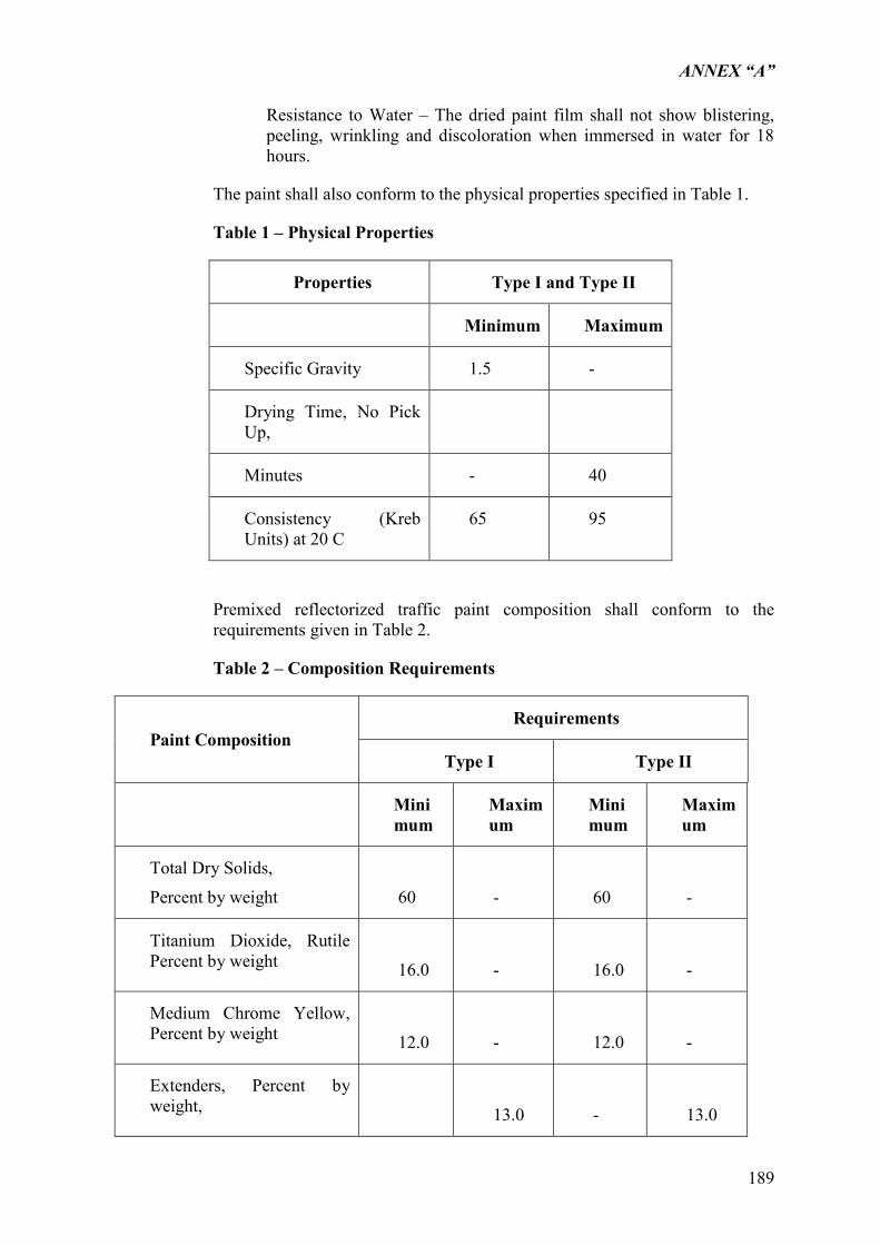
ANNEX “A”
189
Resistance to Water – The dried paint film shall not show blistering, peeling, wrinkling and discoloration when immersed in water for 18 hours.
The paint shall also conform to the physical properties specified in Table 1.
Table 1 – Physical Properties
Properties Type I and Type II
Minimum Maximum
Specific Gravity 1.5 -
Drying Time, No Pick Up,
Minutes - 40
Consistency (Kreb Units) at 20 C
65 95
Premixed reflectorized traffic paint composition shall conform to the requirements given in Table 2.
Table 2 – Composition Requirements
Paint Composition Requirements
Type I Type II
Minimum
Maximum
Minimum
Maximum
Total Dry Solids,
Percent by weight
60
-
60
-
Titanium Dioxide, Rutile Percent by weight
16.0
-
16.0
-
Medium Chrome Yellow, Percent by weight
12.0
-
12.0
-
Extenders, Percent by weight,
13.0
-
13.0
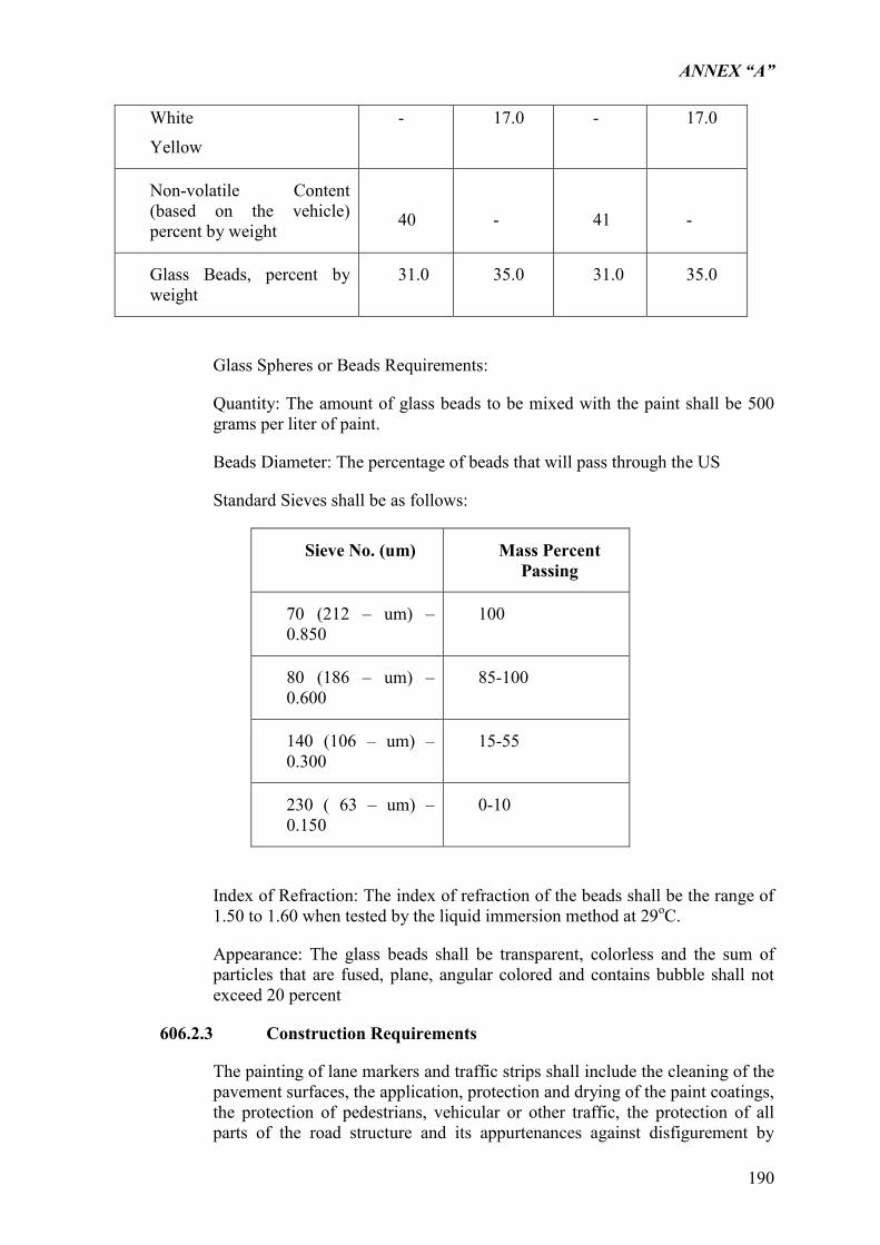
ANNEX “A”
190
White
Yellow
- 17.0 - 17.0
Non-volatile Content (based on the vehicle) percent by weight
40
-
41
-
Glass Beads, percent by weight
31.0 35.0 31.0 35.0
Glass Spheres or Beads Requirements:
Quantity: The amount of glass beads to be mixed with the paint shall be 500 grams per liter of paint.
Beads Diameter: The percentage of beads that will pass through the US
Standard Sieves shall be as follows:
Sieve No. (um) Mass Percent Passing
70 (212 – um) – 0.850
100
80 (186 – um) – 0.600
85-100
140 (106 – um) – 0.300
15-55
230 ( 63 – um) – 0.150
0-10
Index of Refraction: The index of refraction of the beads shall be the range of 1.50 to 1.60 when tested by the liquid immersion method at 29oC.
Appearance: The glass beads shall be transparent, colorless and the sum of particles that are fused, plane, angular colored and contains bubble shall not exceed 20 percent
606.2.3 Construction Requirements
The painting of lane markers and traffic strips shall include the cleaning of the pavement surfaces, the application, protection and drying of the paint coatings, the protection of pedestrians, vehicular or other traffic, the protection of all parts of the road structure and its appurtenances against disfigurement by
ANNEX “A”
191
spatters, splashes or smirches of paints or of paint materials, and the supplying of all tools, labor and traffic paint necessary for the entire work.
The paint shall not be applied during rain or wet weather or when the air is misty, or when in the opinion of the Engineer, conditions are unfavorable for thework. Paint shall not be applied upon damp pavement surfaces, or upon pavement which has absorbed heat sufficient to cause the paint to blister and produce a porous film of paint.
The application of paint shall preferably be carried out by a machine specially made for this purpose but where brushes are used, only round or oval brushes not exceeding 100 mm in width will be permitted. The paint shall be so applied as to produce a uniform, even coating in close contact with the surface being painted.
Traffic paint shall be applied to the pavement at the rate of 0.33 L /m2 and shall dry sufficiently to be free from cracking in from 15 to 30 minutes.
All markings shall present a clean cut, uniform and workmanlike appearance. Markings that fail to have a uniform, satisfactory appearance either by day or night, shall be corrected by the Contractor in a manner acceptable to the Engineer and at no cost to the Government.
606.2.4 Sampling
The paint shall be sampled in accordance with PNS 484/ISO 1512 or other Philippine Standard Method of Sampling Paints and Varnishes.
606.2.5 Test Methods
The paints shall be tested in accordance with the methods specified in PNS 461 or other Philippine Standard Method of Tests for Paints and Varnishes.
606.2.6 Packing, Packaging and Marking
The paints shall be packed, packaged and marked in accordance with PNS 140.
606.3 Method of Measurement
The quantity of pavement markings to be paid for shall either be the length as shown on the Plans of painted traffic line of the stated width or the area as shown on the plans of symbols, lettering, hatchings, and the like, completed and accepted. Separate items shall be provided for premixed reflectorized traffic paint and reflectorized thermoplastic pavement markings.
606.4 Basis of Payment
The quantities measured as determined in Section 606.4, Method of Measurement, shall be paid for at the appropriate contract unit price for the Pay Items shown in the Bid Schedule which price and payment shall constitute full compensation for furnishing and placing all materials, samplingand packing, forthe preparation of the
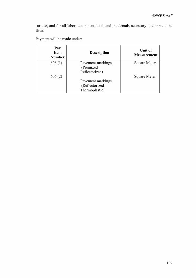
ANNEX “A”
192
surface, and for all labor, equipment, tools and incidentals necessary to complete the Item.
Payment will be made under:
Pay Item
Number Description Unit of
Measurement
606 (1) 606 (2)
Pavement markings (Premixed Reflectorized) Pavement markings (Reflectorized Thermoplastic)
Square Meter Square Meter
Related Documents