An Investigation of Security In Near Field Communication Systems by Steven J. Olivieri A Dissertation Submitted to the Faculty of the WORCESTER POLYTECHNIC INSTITUTE in partial fulfillment of the requirements for the Degree of Doctor of Philosophy in Electrical and Computer Engineering by January 26, 2015 APPROVED: Professor Alexander M. Wyglinski Professor Yunsi Fei WPI, Advisor Northeastern University Professor Fred J. Looft III Professor Xinming Huang WPI WPI Professor Thomas Eisenbarth Professor Craig Shue WPI WPI

Welcome message from author
This document is posted to help you gain knowledge. Please leave a comment to let me know what you think about it! Share it to your friends and learn new things together.
Transcript
An Investigation of Security
In Near Field Communication Systems
by
Steven J. Olivieri
A Dissertation
Submitted to the Faculty
of the
WORCESTER POLYTECHNIC INSTITUTE
in partial fulfillment of the requirements for the
Degree of Doctor of Philosophy
in
Electrical and Computer Engineering
by
January 26, 2015
APPROVED:
Professor Alexander M. Wyglinski Professor Yunsi FeiWPI, Advisor Northeastern University
Professor Fred J. Looft III Professor Xinming HuangWPI WPI
Professor Thomas Eisenbarth Professor Craig ShueWPI WPI
Abstract
Increasingly, goods and services are purchased over the Internet without any form of phys-
ical currency. This practice, often called e-commerce, offers sellers and buyers a convenient
way to trade globally as no physical currency must change hands and buyers from any-
where in the world can browse online store fronts from around the globe. Nevertheless,
many transactions still require a physical presence. For these sorts of transactions, a new
technology called Near Field Communication has emerged to provide buyers with some of
the conveniences of e-commerce while still allowing them to purchase goods locally.
Near Field Communication (NFC), an evolution of Radio-Frequency Identification (RFID),
allows one electronic device to transmit short messages to another nearby device. A buyer
can store his or her payment information on a tag and a cashier can retrieve that information
with an appropriate reader. Advanced devices can store payment information for multiple
credit and debit cards as well as gift cards and other credentials. By consolidating all of
these payment forms into a single device, the buyer has fewer objects to carry with her.
Further, proper implementation of such a device can offer increased security over plastic
cards in the form of advanced encryption.
Using a testing platform consisting of commercial, off-the-shelf components, this disser-
tation investigates the security of the NFC physical-layer protocols as well as the primary
NFC security protocol, NFC-SEC. In addition, it analyzes a situation in which the NFC pro-
tocols appear to break, potentially compromising sensitive data. Finally, this dissertation
provides a proof of security for the NFC-SEC-1 variation of NFC-SEC.

iii
Acknowledgements
First, I must thank Professor Alex Wyglinski, who served as my primary advisor for both of
my graduate degrees at WPI and who read through numerous drafts of every paper that I
have written and provided great feedback each time. He also knows pretty much everybody
and his connections were invaluable for tracking down additional support. Plus, he helped
me to find my current job. Thanks, Professor!
I would also like to thank Professors Yunsi Fei, Fred Looft, Xinming Huang, Thomas
Eisenbarth, and Craig Shue for serving on my dissertation committee and for providing
valuable insight and additions to this dissertation.
To MIT Lincoln Laboratory and LinQuest, thank you for supporting me for the past
few years as I worked to complete my PhD and for your understanding when my schedule
was not quite normal.
To Isaac, Drew, Zebs, Zach, Ben, Allison, Andrea, Tim, Soe San, Tom, Mike, and anyone
else that I’ve forgotten to list here, thank you for making my time at WPI awesome. You
all were always there to distract me from getting work done and to ensure that I did not
lose my mind. Thanks!
My parents, my sister, and Jamie: Hey, I finished. Please don’t call me Dr. Steve. And
also, thanks for everything. Really.
Finally, thanks to Jennifer. You’re the best! I totally wouldn’t have finished without
you. I love you. <3
iv
Contents
List of Figures vii
List of Tables ix
List of Algorithms x
1 Introduction 1
1.1 Research Motivation . . . . . . . . . . . . . . . . . . . . . . . . . . . . . . . 11.2 Current State of the Art . . . . . . . . . . . . . . . . . . . . . . . . . . . . . 21.3 Research Objectives . . . . . . . . . . . . . . . . . . . . . . . . . . . . . . . 31.4 Contributions . . . . . . . . . . . . . . . . . . . . . . . . . . . . . . . . . . . 31.5 Dissertation Organization . . . . . . . . . . . . . . . . . . . . . . . . . . . . 4
2 Near Field Communication 5
2.1 Overview . . . . . . . . . . . . . . . . . . . . . . . . . . . . . . . . . . . . . 52.2 Physical Operation . . . . . . . . . . . . . . . . . . . . . . . . . . . . . . . . 62.3 Protocol . . . . . . . . . . . . . . . . . . . . . . . . . . . . . . . . . . . . . . 8
2.3.1 Analog Interface . . . . . . . . . . . . . . . . . . . . . . . . . . . . . 92.3.2 Digital Interface . . . . . . . . . . . . . . . . . . . . . . . . . . . . . 13
2.3.2.1 Single Device Detection and Initialization . . . . . . . . . . 152.3.2.2 Data Exchange Protocol . . . . . . . . . . . . . . . . . . . 22
2.3.3 Logical Link Control . . . . . . . . . . . . . . . . . . . . . . . . . . . 272.3.3.1 LLCP Frames . . . . . . . . . . . . . . . . . . . . . . . . . 292.3.3.2 MAC Mapping . . . . . . . . . . . . . . . . . . . . . . . . . 302.3.3.3 Activating a Link . . . . . . . . . . . . . . . . . . . . . . . 312.3.3.4 Exchanging Data . . . . . . . . . . . . . . . . . . . . . . . . 322.3.3.5 Deactivating a Link . . . . . . . . . . . . . . . . . . . . . . 34
2.3.4 Simple NDEF Exchange Protocol . . . . . . . . . . . . . . . . . . . . 342.3.5 NFC Data Exchange Format . . . . . . . . . . . . . . . . . . . . . . 37
2.4 Chapter Summary . . . . . . . . . . . . . . . . . . . . . . . . . . . . . . . . 39
3 Cryptography Overview 41
3.1 Advanced Encryption Standard . . . . . . . . . . . . . . . . . . . . . . . . . 413.1.1 Finite Field Math . . . . . . . . . . . . . . . . . . . . . . . . . . . . 43
v
3.1.2 Key Schedule . . . . . . . . . . . . . . . . . . . . . . . . . . . . . . . 443.1.3 AddRoundKey . . . . . . . . . . . . . . . . . . . . . . . . . . . . . . 453.1.4 SubBytes . . . . . . . . . . . . . . . . . . . . . . . . . . . . . . . . . 463.1.5 ShiftRows . . . . . . . . . . . . . . . . . . . . . . . . . . . . . . . . . 473.1.6 MixColumns . . . . . . . . . . . . . . . . . . . . . . . . . . . . . . . 473.1.7 Decryption . . . . . . . . . . . . . . . . . . . . . . . . . . . . . . . . 48
3.2 Diffie-Hellman . . . . . . . . . . . . . . . . . . . . . . . . . . . . . . . . . . . 483.3 Elliptic Curves . . . . . . . . . . . . . . . . . . . . . . . . . . . . . . . . . . 513.4 NFC-SEC . . . . . . . . . . . . . . . . . . . . . . . . . . . . . . . . . . . . . 553.5 NFC-SEC-1 . . . . . . . . . . . . . . . . . . . . . . . . . . . . . . . . . . . . 583.6 Chapter Summary . . . . . . . . . . . . . . . . . . . . . . . . . . . . . . . . 61
4 NFC Protocol Security 63
4.1 Eavesdropping Attacks . . . . . . . . . . . . . . . . . . . . . . . . . . . . . . 634.2 Data Alteration Attacks . . . . . . . . . . . . . . . . . . . . . . . . . . . . . 664.3 Man-in-the-Middle Attacks . . . . . . . . . . . . . . . . . . . . . . . . . . . 684.4 Relay Attacks . . . . . . . . . . . . . . . . . . . . . . . . . . . . . . . . . . . 704.5 Chapter Summary . . . . . . . . . . . . . . . . . . . . . . . . . . . . . . . . 75
5 NFC Testing Platform 76
5.1 Hardware . . . . . . . . . . . . . . . . . . . . . . . . . . . . . . . . . . . . . 765.2 Software . . . . . . . . . . . . . . . . . . . . . . . . . . . . . . . . . . . . . . 805.3 Implementation . . . . . . . . . . . . . . . . . . . . . . . . . . . . . . . . . . 805.4 Chapter Summary . . . . . . . . . . . . . . . . . . . . . . . . . . . . . . . . 82
6 An Analysis of Double Target Trouble 83
6.1 The Problem . . . . . . . . . . . . . . . . . . . . . . . . . . . . . . . . . . . 836.2 Proposed Experiment . . . . . . . . . . . . . . . . . . . . . . . . . . . . . . 846.3 Experimental Results and Analysis . . . . . . . . . . . . . . . . . . . . . . . 856.4 Security Implications . . . . . . . . . . . . . . . . . . . . . . . . . . . . . . . 916.5 Chapter Summary . . . . . . . . . . . . . . . . . . . . . . . . . . . . . . . . 94
7 NFC-SEC Proof of Security 95
7.1 Protocol Composition Logic . . . . . . . . . . . . . . . . . . . . . . . . . . . 957.2 NFC-SEC-1 SSE Algorithm . . . . . . . . . . . . . . . . . . . . . . . . . . . 977.3 The PCL Proof System . . . . . . . . . . . . . . . . . . . . . . . . . . . . . 997.4 Proof of Authentication . . . . . . . . . . . . . . . . . . . . . . . . . . . . . 1027.5 Chapter Summary . . . . . . . . . . . . . . . . . . . . . . . . . . . . . . . . 104
8 Conclusions 106
8.1 Summary and Accomplishments . . . . . . . . . . . . . . . . . . . . . . . . 1068.2 Future Work . . . . . . . . . . . . . . . . . . . . . . . . . . . . . . . . . . . 1078.3 Resulting Publications . . . . . . . . . . . . . . . . . . . . . . . . . . . . . . 108

vi
A Multiplying in Finite Fields 109
A.1 Peasant Algorithm . . . . . . . . . . . . . . . . . . . . . . . . . . . . . . . . 109A.2 Finite Fields . . . . . . . . . . . . . . . . . . . . . . . . . . . . . . . . . . . 111
Bibliography 115
vii
List of Figures
2.1 Regions of an EM field. . . . . . . . . . . . . . . . . . . . . . . . . . . . . . 72.2 Magnetic induction with two NFC devices. . . . . . . . . . . . . . . . . . . 82.3 Structure of the NFC protocol layers. . . . . . . . . . . . . . . . . . . . . . . 92.4 Modified Miller sequences. . . . . . . . . . . . . . . . . . . . . . . . . . . . . 112.5 Manchester encoding for passive fc/128 devices. . . . . . . . . . . . . . . . . 122.6 Manchester encoding for fc/64 or fc/32 devices. . . . . . . . . . . . . . . . . 132.7 Flowchart of a NFC transaction. . . . . . . . . . . . . . . . . . . . . . . . . 142.8 Initial RF Collision Avoidance. . . . . . . . . . . . . . . . . . . . . . . . . . 152.9 Initial active mode configuration. . . . . . . . . . . . . . . . . . . . . . . . . 162.10 Initialization frames for passive fc/128 devices. . . . . . . . . . . . . . . . . . 172.11 Flowchart of the anti-collision algorithm for passive fc/128 devices. . . . . . 192.12 Example of the anti-collision algorithm for passive fc/128 devices. . . . . . . 212.13 Anti-collision frame format for passive fc/64 and fc/64 devices. . . . . . . . . 222.14 Example of the anti-collision algorithm for NFC-F devices. . . . . . . . . . . 222.15 Frame formats for the Data Exchange Protocol. . . . . . . . . . . . . . . . . 232.16 Flowchart of the Data Exchange Protocol for passive communication. . . . 242.17 Flowchart of the Data Exchange Protocol for active communication. . . . . 252.18 Format of the ATR REQ command. . . . . . . . . . . . . . . . . . . . . . . 262.19 Payload of a DEP frame. . . . . . . . . . . . . . . . . . . . . . . . . . . . . 272.20 Structure of the LLC layer. . . . . . . . . . . . . . . . . . . . . . . . . . . . 292.21 Format of the LLCP PDU. . . . . . . . . . . . . . . . . . . . . . . . . . . . 302.22 Example of an ATR REQ that supports LLCP. . . . . . . . . . . . . . . . . 312.23 Simple NDEF Exchange Protocol frame format. . . . . . . . . . . . . . . . . 342.24 Example of a fragmented SNEP message. . . . . . . . . . . . . . . . . . . . 352.25 Format of an NDEF record. . . . . . . . . . . . . . . . . . . . . . . . . . . . 382.26 Format of an NDEF short record. . . . . . . . . . . . . . . . . . . . . . . . . 39
3.1 Illustration of the AES AddRoundKey function. . . . . . . . . . . . . . . . . 463.2 Illustration of the AES ShiftRows function. . . . . . . . . . . . . . . . . . . 473.3 Example of the Diffie-Hellman key exchange algorithm. . . . . . . . . . . . 513.4 The elliptic curve y2 = x3 + x. . . . . . . . . . . . . . . . . . . . . . . . . . 523.5 The elliptic curve y2 = x3 + x over F13. . . . . . . . . . . . . . . . . . . . . 533.6 Example of the Elliptic Curve Diffie-Hellman key exchange algorithm. . . . 54
viii
3.7 Format of the NFC-SEC PDU. . . . . . . . . . . . . . . . . . . . . . . . . . 553.8 Flowchart of the NFC-SEC protocol. . . . . . . . . . . . . . . . . . . . . . . 573.9 Establishing the NFC-SEC-1 shared secret service. . . . . . . . . . . . . . . 593.10 Establishing the NFC-SEC-1 secure channel service. . . . . . . . . . . . . . 603.11 Sending encrypted data with NFC-SEC-1. . . . . . . . . . . . . . . . . . . . 62
4.1 Example of an eavesdropping attack. . . . . . . . . . . . . . . . . . . . . . . 644.2 Data modification attack at 100% ASK. . . . . . . . . . . . . . . . . . . . . 674.3 A man-in-the-middle attack with NFC devices. . . . . . . . . . . . . . . . . 684.4 A typical relay attack with NFC devices. . . . . . . . . . . . . . . . . . . . . 704.5 A long distance relay attack with NFC devices. . . . . . . . . . . . . . . . . 73
5.1 A block diagram of the NFC testing platform. . . . . . . . . . . . . . . . . . 775.2 Photograph of the NFC testing platform. . . . . . . . . . . . . . . . . . . . 78
6.1 Flowchart of the Double Target Trouble experiment. . . . . . . . . . . . . . 856.2 DTT control test. . . . . . . . . . . . . . . . . . . . . . . . . . . . . . . . . . 866.3 DTT test at 424 Kbps active, 0 cm. . . . . . . . . . . . . . . . . . . . . . . 876.4 DTT test at 424 Kbps passive, 0 cm. . . . . . . . . . . . . . . . . . . . . . . 886.5 DTT test at 106 Kbps active, 0 cm. . . . . . . . . . . . . . . . . . . . . . . 896.6 DTT test at 424 Kbps active, 4 cm. . . . . . . . . . . . . . . . . . . . . . . 906.7 DTT test at 424 Kbps passive, 4 cm. . . . . . . . . . . . . . . . . . . . . . . 916.8 DTT test at 106 Kbps active, 4 cm. . . . . . . . . . . . . . . . . . . . . . . 92
7.1 Authentication properties of the NFC-SEC-1 Initiator. . . . . . . . . . . . . 1027.2 Proof of weak authentication for NFC-SEC-1 Initiator. . . . . . . . . . . . . 1037.3 Proof of strong authentication for NFC-SEC-1 Initiator. . . . . . . . . . . . 105
ix
List of Tables
2.1 Comparison of popular wireless technologies. . . . . . . . . . . . . . . . . . 62.2 Modulation and coding schemes used for NFC. . . . . . . . . . . . . . . . . 102.3 Coding of the SAK frame. . . . . . . . . . . . . . . . . . . . . . . . . . . . . 182.4 Service Access Point Address Mapping for LLCP. . . . . . . . . . . . . . . . 302.5 TLVs for NFC-DEP ATR REQ frames. . . . . . . . . . . . . . . . . . . . . 322.6 SNEP request codes. . . . . . . . . . . . . . . . . . . . . . . . . . . . . . . . 362.7 SNEP response codes. . . . . . . . . . . . . . . . . . . . . . . . . . . . . . . 372.8 TNF encoding for NDEF records. . . . . . . . . . . . . . . . . . . . . . . . . 40
3.1 NFC-SEC PDUs. . . . . . . . . . . . . . . . . . . . . . . . . . . . . . . . . . 55
6.1 Double Target Trouble results from Alice’s perspective. . . . . . . . . . . . 93
x
List of Algorithms
3.1 Pseudo code of the AES algorithm. . . . . . . . . . . . . . . . . . . . . . . . 423.2 Pseudo code of the AES key expansion. . . . . . . . . . . . . . . . . . . . . 453.3 Pseudo code of the inverse AES algorithm. . . . . . . . . . . . . . . . . . . 49
7.1 PCL Algorithm for NFC-SEC-1 Initiator. . . . . . . . . . . . . . . . . . . . 977.2 PCL Algorithm for NFC-SEC-1 Target. . . . . . . . . . . . . . . . . . . . . 98
A.1 The modified peasant algorithm in C. . . . . . . . . . . . . . . . . . . . . . 114

1
Chapter 1
Introduction
1.1 Research Motivation
For at least 150,000 years, people have engaged in trade and commerce. Early humans
bartered goods and services directly. As early as 12,000 BCE, civilizations in the Mediter-
ranean region traded with obsidian [1]. By 9,000 BCE, cattle and grain were common forms
of money [2]. Cowrie shells were used in China as early as 1,200 BCE [2]. The first coins
appeared in Lydia (present day Turkey) in 687 BCE [2]. While these first coins were made
from electrum, future coins would be made of bronze, silver, gold, and other metals. Paper
money was first introduced in Song dynasty China in 1024 CE [3].
Today, we have many methods of paying for goods and services. Some transactions still
use coins and bank notes. Others use checks, money orders, and other forms of guarantees.
Still others use credit cards and debit cards. Increasingly, goods and services are purchased
over the Internet without any form of physical currency. This practice, sometimes called
e-commerce [4], offers sellers and buyers a convenient way to trade globally as no physical
currency must change hands and buyers from anywhere in the world can browse online store
fronts from around the globe.
Nevertheless, many transactions still require a physical presence. A driver still purchases
gasoline for his automobile at gas stations, a thirsty athlete might buy a bottle of water from
a vending machine, and the older couple with the convenience store down the road probably
2
doesn’t have an online presence. For these sorts of transactions, a new technology called
Near Field Communication has emerged to provide buyers with some of the conveniences
of e-commerce while still allowing them to purchase goods locally.
Near Field Communication (NFC) allows one electronic device to transmit short mes-
sages to another nearby device. As an evolution of Radio-Frequency Identification (RFID),
NFC also allows such a device to read passive tags. These tags might contain web addresses,
images, product information, or other forms of data. Specifically for financial transactions,
these tags can hold payment credentials. Thus, a buyer can store his or her payment in-
formation on a tag and a cashier can retrieve that information with an appropriate reader.
Advanced devices can store payment information for multiple credit and debit cards as well
as gift cards and other credentials. By consolidating all of these payment forms into a
single device, the buyer has fewer objects to carry with her. Further, proper implementa-
tion of such a device can offer increased security over plastic cards in the form of advanced
encryption.
1.2 Current State of the Art
Today, Near Field Communication is used in a wide variety of applications all over
the world, including parking meters [5], event ticketing [6][7], public transportation [8][9],
hotel keys [10], and in-store payments [11][12][13]. Major credit card companies in the
United States have NFC-enabled devices and payment terminals (e.g. payWave for Visa
[14], PayPass for MasterCard [15]). Google has developed an application called Google
Wallet [16] that enables users to store credit card information on their phones and then use
those phones to pay at MasterCard PayPass terminals. BlackBerry OS [17] and Windows
Phone 8 [18] have similar applications.
Support for NFC in mobile phones is increasingly common in the United States and
elsewhere. Google has added NFC support to its Android operating system and many
device manufacturers have enabled the feature, including HTC [19], Samsung [20], Motorola
[21], and LG Electronics [22]. Many of Research in Motion’s BlackBerry phones support
the technology [23], as do some Windows phones [24]. While most NFC-enabled phones
3
are smart phones, some feature phones also have support for NFC, most notably the Nokia
6131 flip phone, which was the first mass market mobile phone with built-in support [25].
As of late 2014, Apple’s iPhone supports NFC transactions only in a very limited form
called Apple Pay.
1.3 Research Objectives
While Near Field Communication provides many advantages that traditional payment
methods lack, it also has drawbacks. For instance, storing multiple payment credentials
into a single NFC-enabled device produces a single point of failure. Should the NFC-
enabled device be lost or stolen, so too are all of those payment credentials lost. Perhaps
the biggest potential disadvantage to using NFC over other payment methods is that NFC
devices transmit data wirelessly. Wireless transmissions tend to be vulnerable to a number
of malicious attacks, including eavesdropping and relay attacks. With this in mind, the
primary research objectives of this dissertation are the following:
• To provide a comprehensive overview of Near Field Communication technology, public
key cryptography, and other technologies related to NFC mobile payment applications.
• To build a testing platform using commonly available hardware and software that is
capable of emulating realistic NFC transactions.
• To utilize the testing platform to investigate security vulnerabilities in the most com-
monly implemented NFC protocols and specifications, including NFCIP-1 and NFC-
SEC.
1.4 Contributions
In order to complete the tasks described in Section 1.3, this dissertation makes the
following novel contributions:
• A comprehensive overview of the vulnerabilities inherent to NFC transactions, the
current state of research toward exploiting those vulnerabilities, and defenses built
4
into the NFC protocols to thwart them.
• A testing platform that includes microprocessors, NFC controllers, and other hardware
and software commonly found in widely-used mobile devices. This testing platform
allows users to investigate a variety of NFC devices and software combinations for
protocol correctness and vulnerabilities.
• An investigation into a flaw in the NFC single-device detection protocol that exposes
NFC transactions to numerous security problems, including spoofed data and denial
of service attacks.
• A proof of security for the NFC-SEC-1 SSE security protocol, used to establish a
secure channel in the absence of hardware secure elements (e.g. SIM cards) using
Protocol Composition Logic.
A list of publications resulting from this work can be found in Section 8.3.
1.5 Dissertation Organization
The remainder of this dissertation is organized as follows: Chapter 2 provides detailed
descriptions of Near Field Communication technology and Chapter 3 describes the encryp-
tion systems employed by NFC devices; Chapter 4 contains a thorough overview of the
current state of research into exploiting NFC transactions; Chapter 5 describes the hard-
ware, software, and operation of the testing NFC platform; Chapter 6 details a vulnerability
in the NFC single-device detection protocol; Chapter 7 examines the NFC-SEC protocol
with Protocol Compositioon Logic and offers a proof for NFC-SEC-1 SSE; finally, Chap-
ter 8 offers concluding remarks and directions for future research. Appendix A describes an
algorithm for multiplying integers in certain finite fields.
5
Chapter 2
Near Field Communication
This chapter provides an introduction to the near field communication (NFC) technology
used in this dissertation, including a brief overview and history of the technology and a
detailed primer on its operation.
2.1 Overview
Near Field Communication (NFC) technology is fairly new, having first been published
as a standard by Ecma International as ECMA-340 in December, 2002 [27]. Building
upon the ideas established by Radio Frequency Identification (RFID), NFC devices use
short-range radio communication to transfer information. While RFID allowed one-way
communication (e.g., a smart phone reading a passive smart tag), NFC additionally allows
two-way communication (e.g., two smart phones exchanging information). Like many RFID
devices, NFC devices operate in the 13.56 MHz industrial, scientific, and medical (ISM)
band, which is unlicensed worldwide. The operating range of NFC devices is typically less
than five centimeters. Table 2.1 compares NFC technology with some other popular wireless
technologies.
In 2004, the International Organization of Standardization (ISO) and the International
Electrotechnical Commission (IEC) published a revised version of this standard as ISO/IEC
Parts of this Chapter were submitted for publication to Wiley Journal on Wireless Communications andNetworks [26].
6
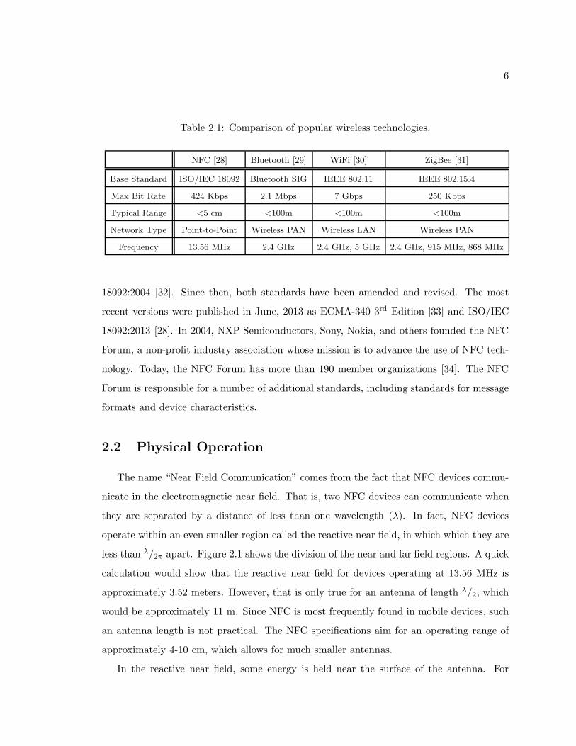
Table 2.1: Comparison of popular wireless technologies.
NFC [28] Bluetooth [29] WiFi [30] ZigBee [31]
Base Standard ISO/IEC 18092 Bluetooth SIG IEEE 802.11 IEEE 802.15.4
Max Bit Rate 424 Kbps 2.1 Mbps 7 Gbps 250 Kbps
Typical Range <5 cm <100m <100m <100m
Network Type Point-to-Point Wireless PAN Wireless LAN Wireless PAN
Frequency 13.56 MHz 2.4 GHz 2.4 GHz, 5 GHz 2.4 GHz, 915 MHz, 868 MHz
18092:2004 [32]. Since then, both standards have been amended and revised. The most
recent versions were published in June, 2013 as ECMA-340 3rd Edition [33] and ISO/IEC
18092:2013 [28]. In 2004, NXP Semiconductors, Sony, Nokia, and others founded the NFC
Forum, a non-profit industry association whose mission is to advance the use of NFC tech-
nology. Today, the NFC Forum has more than 190 member organizations [34]. The NFC
Forum is responsible for a number of additional standards, including standards for message
formats and device characteristics.
2.2 Physical Operation
The name “Near Field Communication” comes from the fact that NFC devices commu-
nicate in the electromagnetic near field. That is, two NFC devices can communicate when
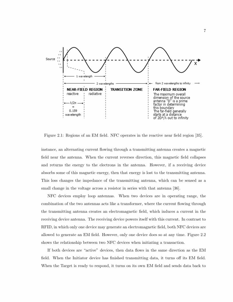
they are separated by a distance of less than one wavelength (λ). In fact, NFC devices
operate within an even smaller region called the reactive near field, in which which they are
less than λ/2π apart. Figure 2.1 shows the division of the near and far field regions. A quick
calculation would show that the reactive near field for devices operating at 13.56 MHz is
approximately 3.52 meters. However, that is only true for an antenna of length λ/2, which
would be approximately 11 m. Since NFC is most frequently found in mobile devices, such
an antenna length is not practical. The NFC specifications aim for an operating range of
approximately 4-10 cm, which allows for much smaller antennas.
In the reactive near field, some energy is held near the surface of the antenna. For
7
Figure 2.1: Regions of an EM field. NFC operates in the reactive near field region [35].
instance, an alternating current flowing through a transmitting antenna creates a magnetic
field near the antenna. When the current reverses direction, this magnetic field collapses
and returns the energy to the electrons in the antenna. However, if a receiving device
absorbs some of this magnetic energy, then that energy is lost to the transmitting antenna.
This loss changes the impedance of the transmitting antenna, which can be sensed as a
small change in the voltage across a resistor in series with that antenna [36].
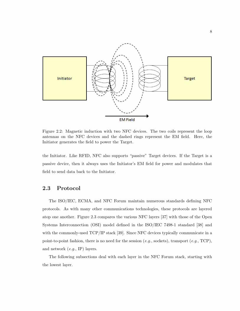
NFC devices employ loop antennas. When two devices are in operating range, the
combination of the two antennas acts like a transformer, where the current flowing through
the transmitting antenna creates an electromagnetic field, which induces a current in the
receiving device antenna. The receiving device powers itself with this current. In contrast to
RFID, in which only one device may generate an electromagnetic field, both NFC devices are
allowed to generate an EM field. However, only one device does so at any time. Figure 2.2
shows the relationship between two NFC devices when initiating a transaction.
If both devices are “active” devices, then data flows in the same direction as the EM
field. When the Initiator device has finished transmitting data, it turns off its EM field.
When the Target is ready to respond, it turns on its own EM field and sends data back to
8
Figure 2.2: Magnetic induction with two NFC devices. The two coils represent the loopantennas on the NFC devices and the dashed rings represent the EM field. Here, theInitiator generates the field to power the Target.
the Initiator. Like RFID, NFC also supports “passive” Target devices. If the Target is a
passive device, then it always uses the Initiator’s EM field for power and modulates that
field to send data back to the Initiator.
2.3 Protocol
The ISO/IEC, ECMA, and NFC Forum maintain numerous standards defining NFC
protocols. As with many other communications technologies, these protocols are layered
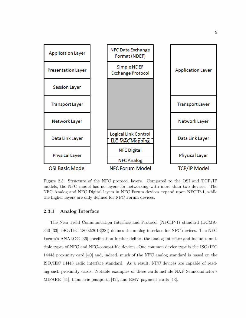
atop one another. Figure 2.3 compares the various NFC layers [37] with those of the Open
Systems Interconnection (OSI) model defined in the ISO/IEC 7498-1 standard [38] and
with the commonly-used TCP/IP stack [39]. Since NFC devices typically communicate in a
point-to-point fashion, there is no need for the session (e.g., sockets), transport (e.g., TCP),
and network (e.g., IP) layers.
The following subsections deal with each layer in the NFC Forum stack, starting with
the lowest layer.
9
Figure 2.3: Structure of the NFC protocol layers. Compared to the OSI and TCP/IPmodels, the NFC model has no layers for networking with more than two devices. TheNFC Analog and NFC Digital layers in NFC Forum devices expand upon NFCIP-1, whilethe higher layers are only defined for NFC Forum devices.
2.3.1 Analog Interface
The Near Field Communication Interface and Protocol (NFCIP-1) standard (ECMA-
340 [33], ISO/IEC 18092:2013[28]) defines the analog interface for NFC devices. The NFC
Forum’s ANALOG [36] specification further defines the analog interface and includes mul-
tiple types of NFC and NFC-compatible devices. One common device type is the ISO/IEC
14443 proximity card [40] and, indeed, much of the NFC analog standard is based on the
ISO/IEC 14443 radio interface standard. As a result, NFC devices are capable of read-
ing such proximity cards. Notable examples of these cards include NXP Semiconductor’s
MIFARE [41], biometric passports [42], and EMV payment cards [43].
10
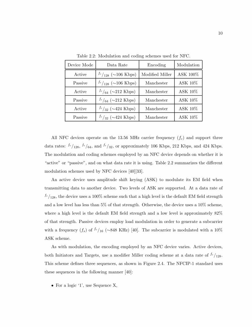
Table 2.2: Modulation and coding schemes used for NFC.
Device Mode Data Rate Encoding Modulation
Active fc/128 (∼106 Kbps) Modified Miller ASK 100%
Passive fc/128 (∼106 Kbps) Manchester ASK 10%
Active fc/64 (∼212 Kbps) Manchester ASK 10%
Passive fc/64 (∼212 Kbps) Manchester ASK 10%
Active fc/32 (∼424 Kbps) Manchester ASK 10%
Passive fc/32 (∼424 Kbps) Manchester ASK 10%
All NFC devices operate on the 13.56 MHz carrier frequency (fc) and support three
data rates: fc/128,fc/64, and
fc/32, or approximately 106 Kbps, 212 Kbps, and 424 Kbps.
The modulation and coding schemes employed by an NFC device depends on whether it is
“active” or “passive”, and on what data rate it is using. Table 2.2 summarizes the different
modulation schemes used by NFC devices [40][33].
An active device uses amplitude shift keying (ASK) to modulate its EM field when
transmitting data to another device. Two levels of ASK are supported. At a data rate of
fc/128, the device uses a 100% scheme such that a high level is the default EM field strength
and a low level has less than 5% of that strength. Otherwise, the device uses a 10% scheme,
where a high level is the default EM field strength and a low level is approximately 82%
of that strength. Passive devices employ load modulation in order to generate a subcarrier
with a frequency (fs) of fc/16 (∼848 KHz) [40]. The subcarrier is modulated with a 10%
ASK scheme.
As with modulation, the encoding employed by an NFC device varies. Active devices,
both Initiators and Targets, use a modifier Miller coding scheme at a data rate of fc/128.
This scheme defines three sequences, as shown in Figure 2.4. The NFCIP-1 standard uses
these sequences in the following manner [40]:
• For a logic ‘1’, use Sequence X,
11
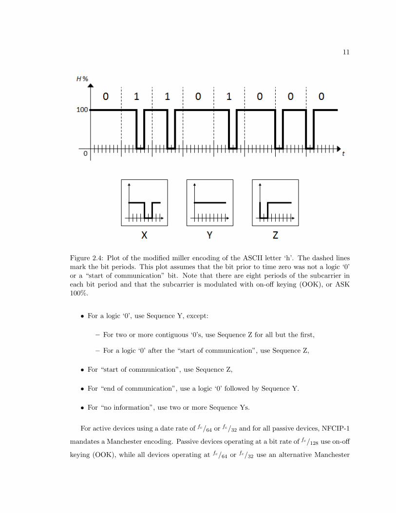
Figure 2.4: Plot of the modified miller encoding of the ASCII letter ‘h’. The dashed linesmark the bit periods. This plot assumes that the bit prior to time zero was not a logic ‘0’or a “start of communication” bit. Note that there are eight periods of the subcarrier ineach bit period and that the subcarrier is modulated with on-off keying (OOK), or ASK100%.
• For a logic ‘0’, use Sequence Y, except:
– For two or more contiguous ‘0’s, use Sequence Z for all but the first,
– For a logic ‘0’ after the “start of communication”, use Sequence Z,
• For “start of communication”, use Sequence Z,
• For “end of communication”, use a logic ‘0’ followed by Sequence Y.
• For “no information”, use two or more Sequence Ys.
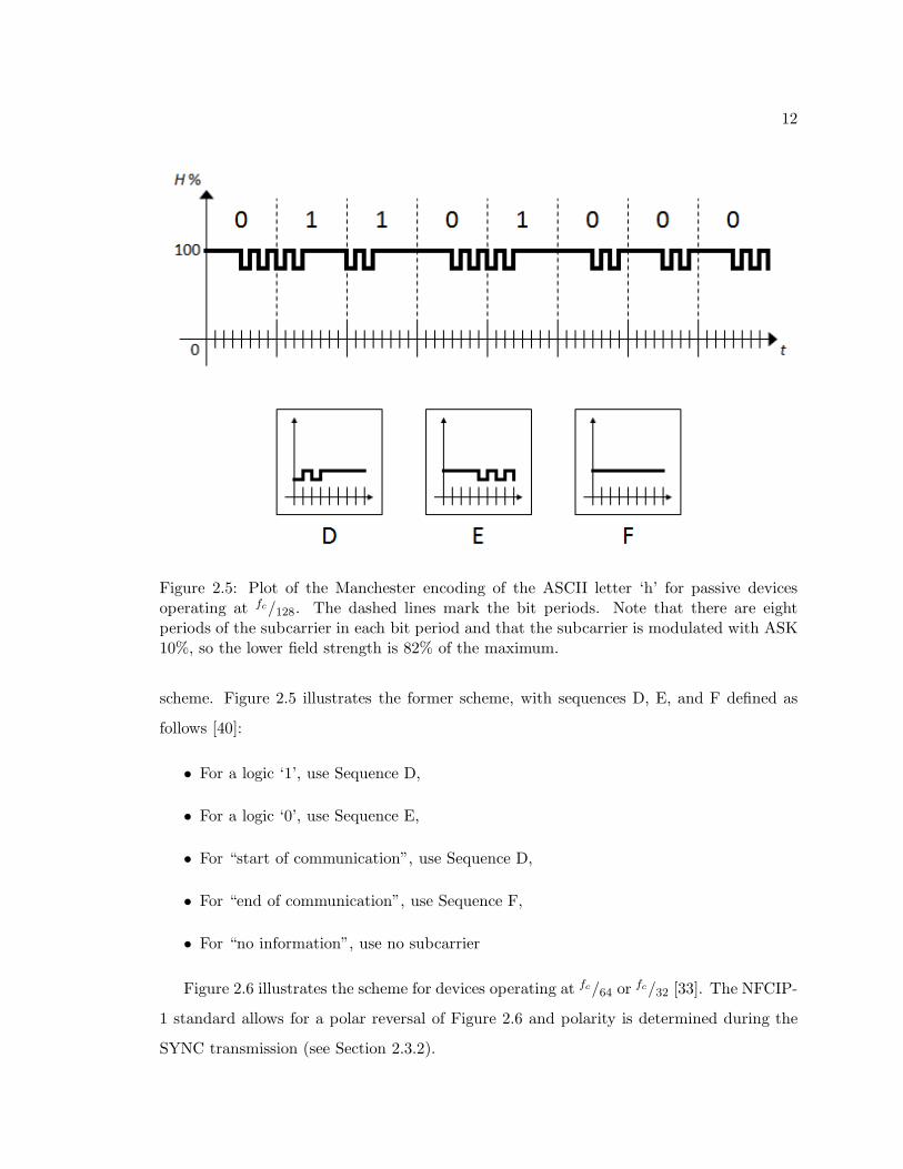
For active devices using a date rate of fc/64 orfc/32 and for all passive devices, NFCIP-1
mandates a Manchester encoding. Passive devices operating at a bit rate of fc/128 use on-off
keying (OOK), while all devices operating at fc/64 or fc/32 use an alternative Manchester
12
Figure 2.5: Plot of the Manchester encoding of the ASCII letter ‘h’ for passive devicesoperating at fc/128. The dashed lines mark the bit periods. Note that there are eightperiods of the subcarrier in each bit period and that the subcarrier is modulated with ASK10%, so the lower field strength is 82% of the maximum.
scheme. Figure 2.5 illustrates the former scheme, with sequences D, E, and F defined as
follows [40]:
• For a logic ‘1’, use Sequence D,
• For a logic ‘0’, use Sequence E,
• For “start of communication”, use Sequence D,
• For “end of communication”, use Sequence F,
• For “no information”, use no subcarrier
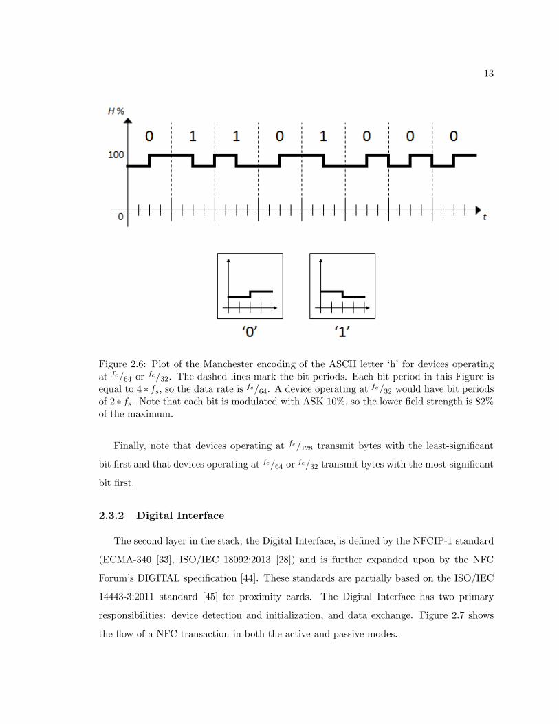
Figure 2.6 illustrates the scheme for devices operating at fc/64 orfc/32 [33]. The NFCIP-
1 standard allows for a polar reversal of Figure 2.6 and polarity is determined during the
SYNC transmission (see Section 2.3.2).
13
Figure 2.6: Plot of the Manchester encoding of the ASCII letter ‘h’ for devices operatingat fc/64 or fc/32. The dashed lines mark the bit periods. Each bit period in this Figure isequal to 4 ∗ fs, so the data rate is fc/64. A device operating at fc/32 would have bit periodsof 2 ∗ fs. Note that each bit is modulated with ASK 10%, so the lower field strength is 82%of the maximum.
Finally, note that devices operating at fc/128 transmit bytes with the least-significant
bit first and that devices operating at fc/64 orfc/32 transmit bytes with the most-significant
bit first.
2.3.2 Digital Interface
The second layer in the stack, the Digital Interface, is defined by the NFCIP-1 standard
(ECMA-340 [33], ISO/IEC 18092:2013 [28]) and is further expanded upon by the NFC
Forum’s DIGITAL specification [44]. These standards are partially based on the ISO/IEC
14443-3:2011 standard [45] for proximity cards. The Digital Interface has two primary
responsibilities: device detection and initialization, and data exchange. Figure 2.7 shows
the flow of a NFC transaction in both the active and passive modes.
14
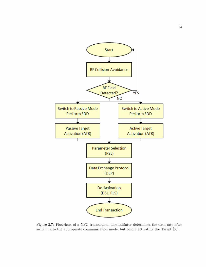
Figure 2.7: Flowchart of a NFC transaction. The Initiator determines the data rate afterswitching to the appropriate communication mode, but before activating the Target [33].
15
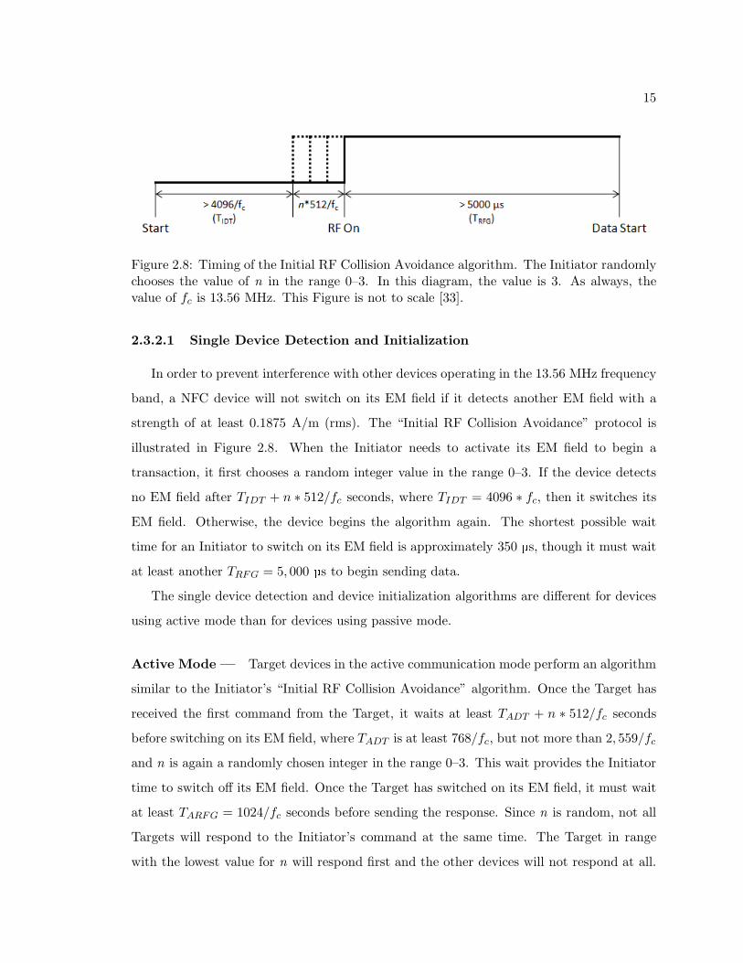
Figure 2.8: Timing of the Initial RF Collision Avoidance algorithm. The Initiator randomlychooses the value of n in the range 0–3. In this diagram, the value is 3. As always, thevalue of fc is 13.56 MHz. This Figure is not to scale [33].
2.3.2.1 Single Device Detection and Initialization
In order to prevent interference with other devices operating in the 13.56 MHz frequency
band, a NFC device will not switch on its EM field if it detects another EM field with a
strength of at least 0.1875 A/m (rms). The “Initial RF Collision Avoidance” protocol is
illustrated in Figure 2.8. When the Initiator needs to activate its EM field to begin a
transaction, it first chooses a random integer value in the range 0–3. If the device detects
no EM field after TIDT + n ∗ 512/fc seconds, where TIDT = 4096 ∗ fc, then it switches its
EM field. Otherwise, the device begins the algorithm again. The shortest possible wait
time for an Initiator to switch on its EM field is approximately 350 µs, though it must wait
at least another TRFG = 5, 000 µs to begin sending data.
The single device detection and device initialization algorithms are different for devices
using active mode than for devices using passive mode.
Active Mode — Target devices in the active communication mode perform an algorithm
similar to the Initiator’s “Initial RF Collision Avoidance” algorithm. Once the Target has
received the first command from the Target, it waits at least TADT + n ∗ 512/fc seconds
before switching on its EM field, where TADT is at least 768/fc, but not more than 2, 559/fc
and n is again a randomly chosen integer in the range 0–3. This wait provides the Initiator
time to switch off its EM field. Once the Target has switched on its EM field, it must wait
at least TARFG = 1024/fc seconds before sending the response. Since n is random, not all
Targets will respond to the Initiator’s command at the same time. The Target in range
with the lowest value for n will respond first and the other devices will not respond at all.
16
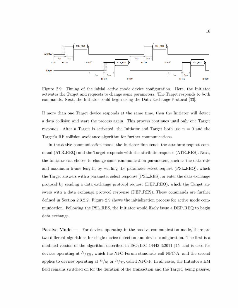
Figure 2.9: Timing of the initial active mode device configuration. Here, the Initiatoractivates the Target and requests to change some parameters. The Target responds to bothcommands. Next, the Initiator could begin using the Data Exchange Protocol [33].
If more than one Target device responds at the same time, then the Initiator will detect
a data collision and start the process again. This process continues until only one Target
responds. After a Target is activated, the Initiator and Target both use n = 0 and the
Target’s RF collision avoidance algorithm for further communications.
In the active communication mode, the Initiator first sends the attribute request com-
mand (ATR REQ) and the Target responds with the attribute response (ATR RES). Next,
the Initiator can choose to change some communication parameters, such as the data rate
and maximum frame length, by sending the parameter select request (PSL REQ), which
the Target answers with a parameter select response (PSL RES), or enter the data exchange
protocol by sending a data exchange protocol request (DEP REQ), which the Target an-
swers with a data exchange protocol response (DEP RES). These commands are further
defined in Section 2.3.2.2. Figure 2.9 shows the initialization process for active mode com-
munication. Following the PSL RES, the Initiator would likely issue a DEP REQ to begin
data exchange.
Passive Mode — For devices operating in the passive communication mode, there are
two different algorithms for single device detection and device configuration. The first is a
modified version of the algorithm described in ISO/IEC 14443-3:2011 [45] and is used for
devices operating at fc/128, which the NFC Forum standards call NFC-A, and the second
applies to devices operating at fc/64 or fc/32, called NFC-F. In all cases, the Initiator’s EM
field remains switched on for the duration of the transaction and the Target, being passive,

17
Figure 2.10: a) A short frame, used for starting communication. b) A standard frame, usedfor most commands. Standard frames can have n ≥ 1 bytes and each byte has odd parity,P. This Figure shows a frame with 2 bytes. c) A bit-oriented frame used for single-devicedetection. Here, the Initiator sends three full bytes and three additional bits; the Targetsends the remaining five bits of that byte and then three more full bytes. The total numberof bits in a bit-oriented frame is always 56, but the split can occur anywhere. If the splitoccurs mid-byte, as it does in this Figure, then the parity bit for the split byte is ignored.
never generates its own field.
NFC-A Devices — The first algorithm, used for devices operating at fc/128 in passive
mode, employs three types of frames, as shown in Figure 2.10. Short frames are used to begin
transactions, bit-oriented SDD frames are used for the single-device detection algorithm,
and standard frames are used for all other commands and data. All frames are transmitted
in pairs so that each request from the Initiator is paired with a response from the Target.
The time that the Target must wait before sending a response depends on the request that
the Initiator sent. For the commands used in the anti-collision algorithm, devices must use
a value of 1236/fc so that they respond synchronously. For other commands, the delay can
be longer, but not shorter. The time that the Initiator waits after receiving a response is
at least 1772/fc.
The first command that the Initiator sends is sense request (SENS REQ), a short frame,
which all Target devices in range answer with sense response (SENS RES), a standard
frame of two bytes. If only one device responds, then the Initiator sends out a single-
device detection request (SDD REQ) to get the device’s unique ID (NFCID1). The Target
responds with its NFCID1 (SDD RES). Next, the Initiator sends out a SEL REQ command
with the Target’s NFCID1 and the Target responds with a select acknowledge (SAK). If the
18
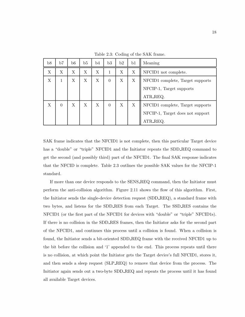
Table 2.3: Coding of the SAK frame.
b8 b7 b6 b5 b4 b3 b2 b1 Meaning
X X X X X 1 X X NFCID1 not complete.
X 1 X X X 0 X X NFCID1 complete, Target supports
NFCIP-1, Target supports
ATR REQ.
X 0 X X X 0 X X NFCID1 complete, Target supports
NFCIP-1, Target does not support
ATR REQ.
SAK frame indicates that the NFCID1 is not complete, then this particular Target device
has a “double” or “triple” NFCID1 and the Initiator repeats the SDD REQ command to
get the second (and possibly third) part of the NFCID1. The final SAK response indicates
that the NFCID is complete. Table 2.3 outlines the possible SAK values for the NFCIP-1
standard.
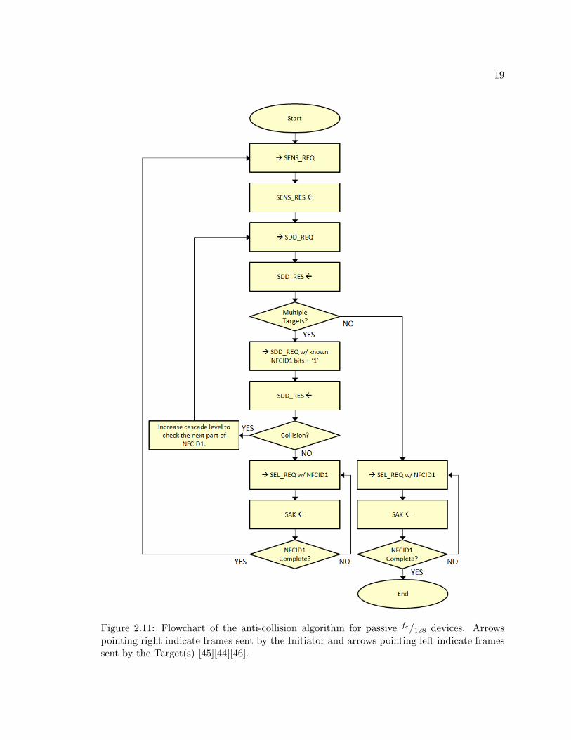
If more than one device responds to the SENS REQ command, then the Initiator must
perform the anti-collision algorithm. Figure 2.11 shows the flow of this algorithm. First,
the Initiator sends the single-device detection request (SDD REQ), a standard frame with
two bytes, and listens for the SDD RES from each Target. The SSD RES contains the
NFCID1 (or the first part of the NFCID1 for devices with “double” or “triple” NFCID1s).
If there is no collision in the SDD RES frames, then the Initiator asks for the second part
of the NFCID1, and continues this process until a collision is found. When a collision is
found, the Initiator sends a bit-oriented SDD REQ frame with the received NFCID1 up to
the bit before the collision and ‘1’ appended to the end. This process repeats until there
is no collision, at which point the Initiator gets the Target device’s full NFCID1, stores it,
and then sends a sleep request (SLP REQ) to remove that device from the process. The
Initiator again sends out a two-byte SDD REQ and repeats the process until it has found
all available Target devices.
19
Figure 2.11: Flowchart of the anti-collision algorithm for passive fc/128 devices. Arrowspointing right indicate frames sent by the Initiator and arrows pointing left indicate framessent by the Target(s) [45][44][46].
20
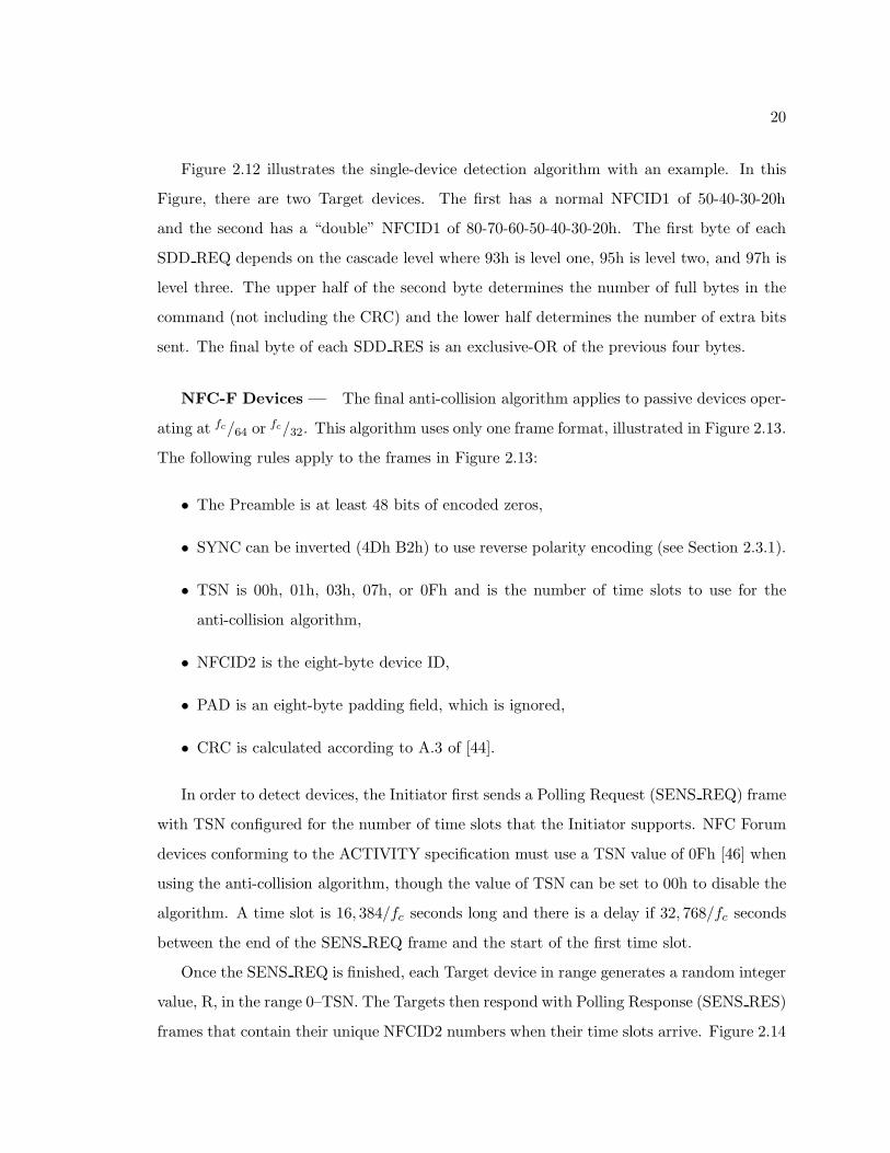
Figure 2.12 illustrates the single-device detection algorithm with an example. In this
Figure, there are two Target devices. The first has a normal NFCID1 of 50-40-30-20h
and the second has a “double” NFCID1 of 80-70-60-50-40-30-20h. The first byte of each
SDD REQ depends on the cascade level where 93h is level one, 95h is level two, and 97h is
level three. The upper half of the second byte determines the number of full bytes in the
command (not including the CRC) and the lower half determines the number of extra bits
sent. The final byte of each SDD RES is an exclusive-OR of the previous four bytes.
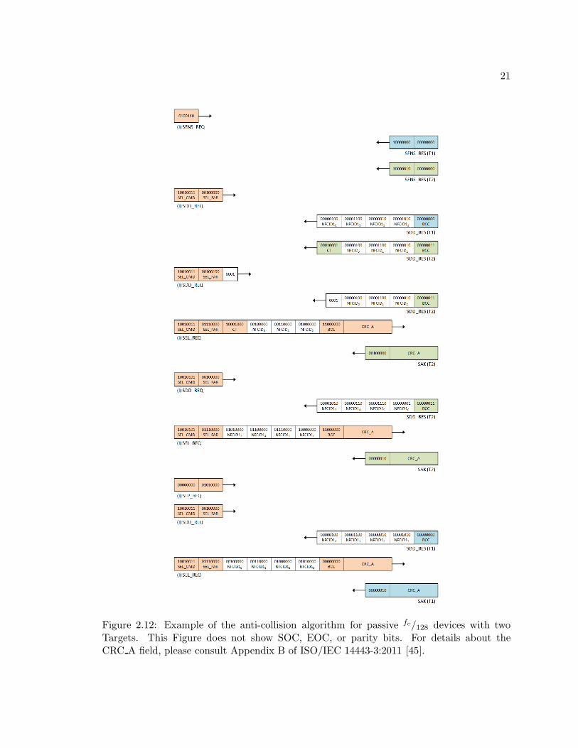
NFC-F Devices — The final anti-collision algorithm applies to passive devices oper-
ating at fc/64 orfc/32. This algorithm uses only one frame format, illustrated in Figure 2.13.
The following rules apply to the frames in Figure 2.13:
• The Preamble is at least 48 bits of encoded zeros,
• SYNC can be inverted (4Dh B2h) to use reverse polarity encoding (see Section 2.3.1).
• TSN is 00h, 01h, 03h, 07h, or 0Fh and is the number of time slots to use for the
anti-collision algorithm,
• NFCID2 is the eight-byte device ID,
• PAD is an eight-byte padding field, which is ignored,
• CRC is calculated according to A.3 of [44].
In order to detect devices, the Initiator first sends a Polling Request (SENS REQ) frame
with TSN configured for the number of time slots that the Initiator supports. NFC Forum
devices conforming to the ACTIVITY specification must use a TSN value of 0Fh [46] when
using the anti-collision algorithm, though the value of TSN can be set to 00h to disable the
algorithm. A time slot is 16, 384/fc seconds long and there is a delay if 32, 768/fc seconds
between the end of the SENS REQ frame and the start of the first time slot.
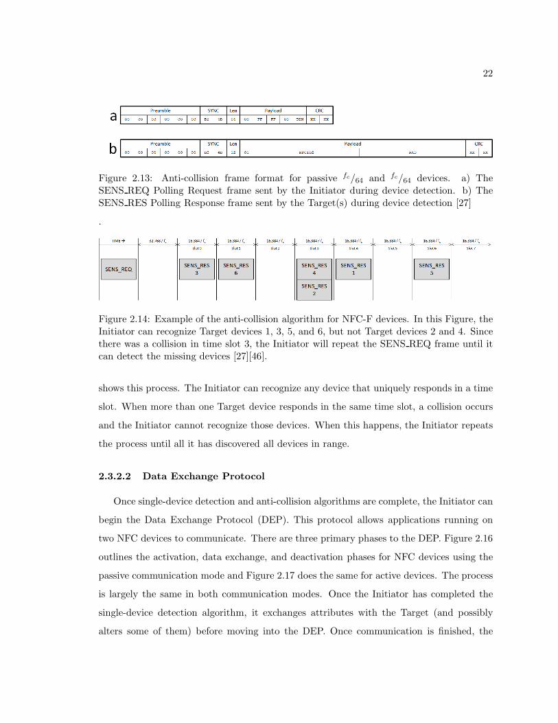
Once the SENS REQ is finished, each Target device in range generates a random integer
value, R, in the range 0–TSN. The Targets then respond with Polling Response (SENS RES)
frames that contain their unique NFCID2 numbers when their time slots arrive. Figure 2.14
21
Figure 2.12: Example of the anti-collision algorithm for passive fc/128 devices with twoTargets. This Figure does not show SOC, EOC, or parity bits. For details about theCRC A field, please consult Appendix B of ISO/IEC 14443-3:2011 [45].
22
Figure 2.13: Anti-collision frame format for passive fc/64 and fc/64 devices. a) TheSENS REQ Polling Request frame sent by the Initiator during device detection. b) TheSENS RES Polling Response frame sent by the Target(s) during device detection [27]
.
Figure 2.14: Example of the anti-collision algorithm for NFC-F devices. In this Figure, theInitiator can recognize Target devices 1, 3, 5, and 6, but not Target devices 2 and 4. Sincethere was a collision in time slot 3, the Initiator will repeat the SENS REQ frame until itcan detect the missing devices [27][46].
shows this process. The Initiator can recognize any device that uniquely responds in a time
slot. When more than one Target device responds in the same time slot, a collision occurs
and the Initiator cannot recognize those devices. When this happens, the Initiator repeats
the process until all it has discovered all devices in range.
2.3.2.2 Data Exchange Protocol
Once single-device detection and anti-collision algorithms are complete, the Initiator can
begin the Data Exchange Protocol (DEP). This protocol allows applications running on
two NFC devices to communicate. There are three primary phases to the DEP. Figure 2.16
outlines the activation, data exchange, and deactivation phases for NFC devices using the
passive communication mode and Figure 2.17 does the same for active devices. The process
is largely the same in both communication modes. Once the Initiator has completed the
single-device detection algorithm, it exchanges attributes with the Target (and possibly
alters some of them) before moving into the DEP. Once communication is finished, the
23
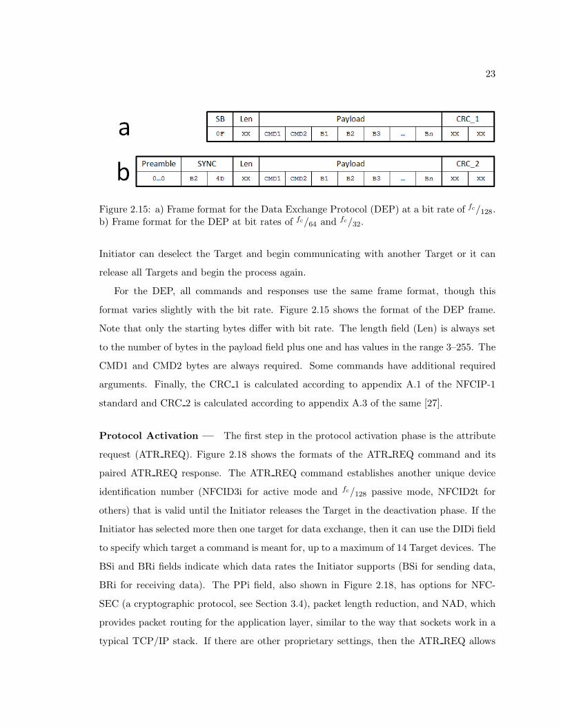
Figure 2.15: a) Frame format for the Data Exchange Protocol (DEP) at a bit rate of fc/128.b) Frame format for the DEP at bit rates of fc/64 and fc/32.
Initiator can deselect the Target and begin communicating with another Target or it can
release all Targets and begin the process again.
For the DEP, all commands and responses use the same frame format, though this
format varies slightly with the bit rate. Figure 2.15 shows the format of the DEP frame.
Note that only the starting bytes differ with bit rate. The length field (Len) is always set
to the number of bytes in the payload field plus one and has values in the range 3–255. The
CMD1 and CMD2 bytes are always required. Some commands have additional required
arguments. Finally, the CRC 1 is calculated according to appendix A.1 of the NFCIP-1
standard and CRC 2 is calculated according to appendix A.3 of the same [27].
Protocol Activation — The first step in the protocol activation phase is the attribute
request (ATR REQ). Figure 2.18 shows the formats of the ATR REQ command and its
paired ATR REQ response. The ATR REQ command establishes another unique device
identification number (NFCID3i for active mode and fc/128 passive mode, NFCID2t for
others) that is valid until the Initiator releases the Target in the deactivation phase. If the
Initiator has selected more then one target for data exchange, then it can use the DIDi field
to specify which target a command is meant for, up to a maximum of 14 Target devices. The
BSi and BRi fields indicate which data rates the Initiator supports (BSi for sending data,
BRi for receiving data). The PPi field, also shown in Figure 2.18, has options for NFC-
SEC (a cryptographic protocol, see Section 3.4), packet length reduction, and NAD, which
provides packet routing for the application layer, similar to the way that sockets work in a
typical TCP/IP stack. If there are other proprietary settings, then the ATR REQ allows

24
Figure 2.16: Flowchart of the Data Exchange Protocol for passive communication. If aTarget does not support the ATR REQ command, then it is not NFCIP-1 compliant andthus NFC-DEP is not possible [27][46].
25
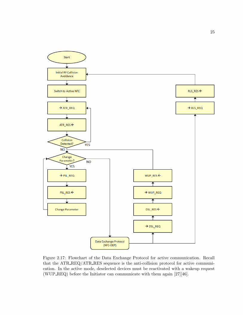
Figure 2.17: Flowchart of the Data Exchange Protocol for active communication. Recallthat the ATR REQ/ATR RES sequence is the anti-collision protocol for active communi-cation. In the active mode, deselected devices must be reactivated with a wakeup request(WUP REQ) before the Initiator can communicate with them again [27][46].
26
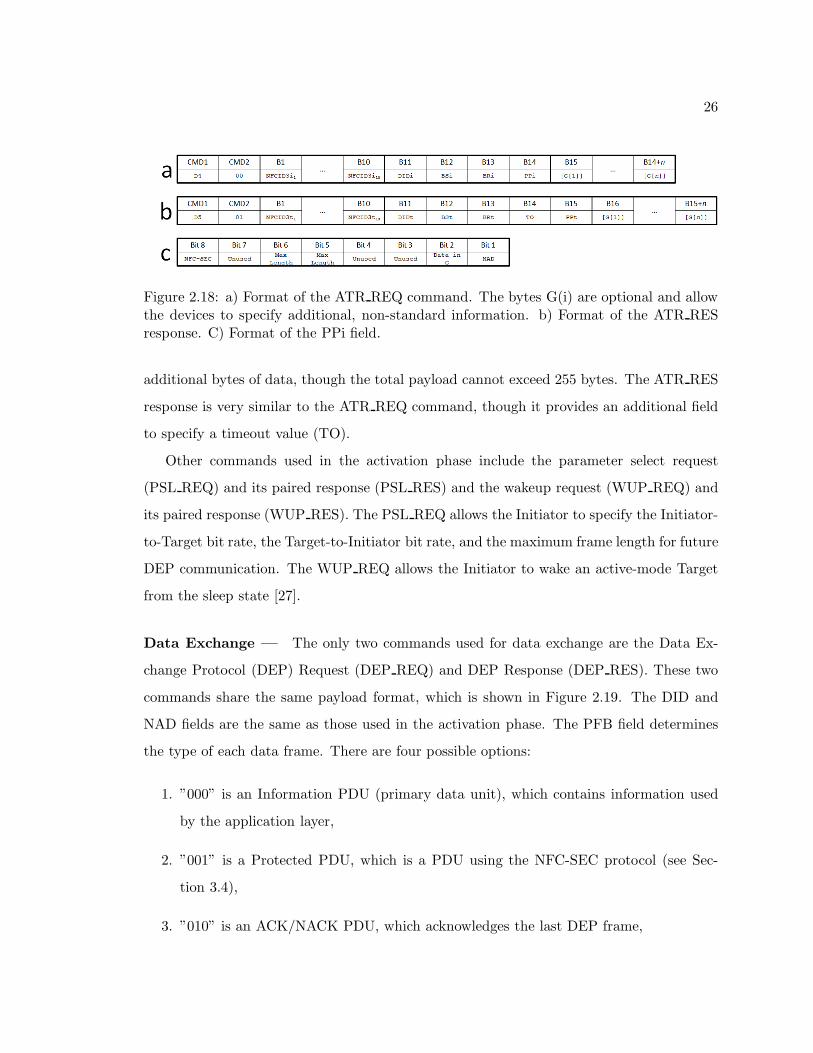
Figure 2.18: a) Format of the ATR REQ command. The bytes G(i) are optional and allowthe devices to specify additional, non-standard information. b) Format of the ATR RESresponse. C) Format of the PPi field.
additional bytes of data, though the total payload cannot exceed 255 bytes. The ATR RES
response is very similar to the ATR REQ command, though it provides an additional field
to specify a timeout value (TO).
Other commands used in the activation phase include the parameter select request
(PSL REQ) and its paired response (PSL RES) and the wakeup request (WUP REQ) and
its paired response (WUP RES). The PSL REQ allows the Initiator to specify the Initiator-
to-Target bit rate, the Target-to-Initiator bit rate, and the maximum frame length for future
DEP communication. The WUP REQ allows the Initiator to wake an active-mode Target
from the sleep state [27].
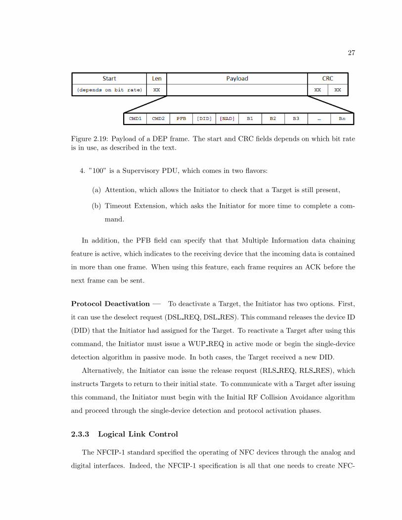
Data Exchange — The only two commands used for data exchange are the Data Ex-
change Protocol (DEP) Request (DEP REQ) and DEP Response (DEP RES). These two
commands share the same payload format, which is shown in Figure 2.19. The DID and
NAD fields are the same as those used in the activation phase. The PFB field determines
the type of each data frame. There are four possible options:
1. ”000” is an Information PDU (primary data unit), which contains information used
by the application layer,
2. ”001” is a Protected PDU, which is a PDU using the NFC-SEC protocol (see Sec-
tion 3.4),
3. ”010” is an ACK/NACK PDU, which acknowledges the last DEP frame,
27
Figure 2.19: Payload of a DEP frame. The start and CRC fields depends on which bit rateis in use, as described in the text.
4. ”100” is a Supervisory PDU, which comes in two flavors:
(a) Attention, which allows the Initiator to check that a Target is still present,
(b) Timeout Extension, which asks the Initiator for more time to complete a com-
mand.
In addition, the PFB field can specify that that Multiple Information data chaining
feature is active, which indicates to the receiving device that the incoming data is contained
in more than one frame. When using this feature, each frame requires an ACK before the
next frame can be sent.
Protocol Deactivation — To deactivate a Target, the Initiator has two options. First,
it can use the deselect request (DSL REQ, DSL RES). This command releases the device ID
(DID) that the Initiator had assigned for the Target. To reactivate a Target after using this
command, the Initiator must issue a WUP REQ in active mode or begin the single-device
detection algorithm in passive mode. In both cases, the Target received a new DID.
Alternatively, the Initiator can issue the release request (RLS REQ, RLS RES), which
instructs Targets to return to their initial state. To communicate with a Target after issuing
this command, the Initiator must begin with the Initial RF Collision Avoidance algorithm
and proceed through the single-device detection and protocol activation phases.
2.3.3 Logical Link Control
The NFCIP-1 standard specified the operating of NFC devices through the analog and
digital interfaces. Indeed, the NFCIP-1 specification is all that one needs to create NFC-
28
compliant devices. However, the NFC Forum maintains its own collection of NFC standards
that further clarify and expand the ISO/IEC standards. Some of these standards clarify
existing ISO/IEC standards, such as ANALOG [36], DIGITAL [44], and ACTIVITY [46].
Others add new functionality on top of the underlying NFCIP-1 specifications. The next
layer in the stack is the Logical Link Control Protocol (LLCP), which is specified by the
LLCP standard from the NFC Forum [37]. This layer is approximately equivalent to the
top half of the OSI model’s Data Link Layer (see Figure 2.3).
The LLCP simplifies the transfer of data from one NFC device to another by providing a
uniform interface to higher layers in the stack. Among the features that the LLCP provides
are link activation, supervision, and deactivation, aggregation and disaggregation of smaller
digital-layer frames, and a “synchronous balanced transfer mode”, which allows Target
devices to initiate communication and manage connections. This last feature contrasts
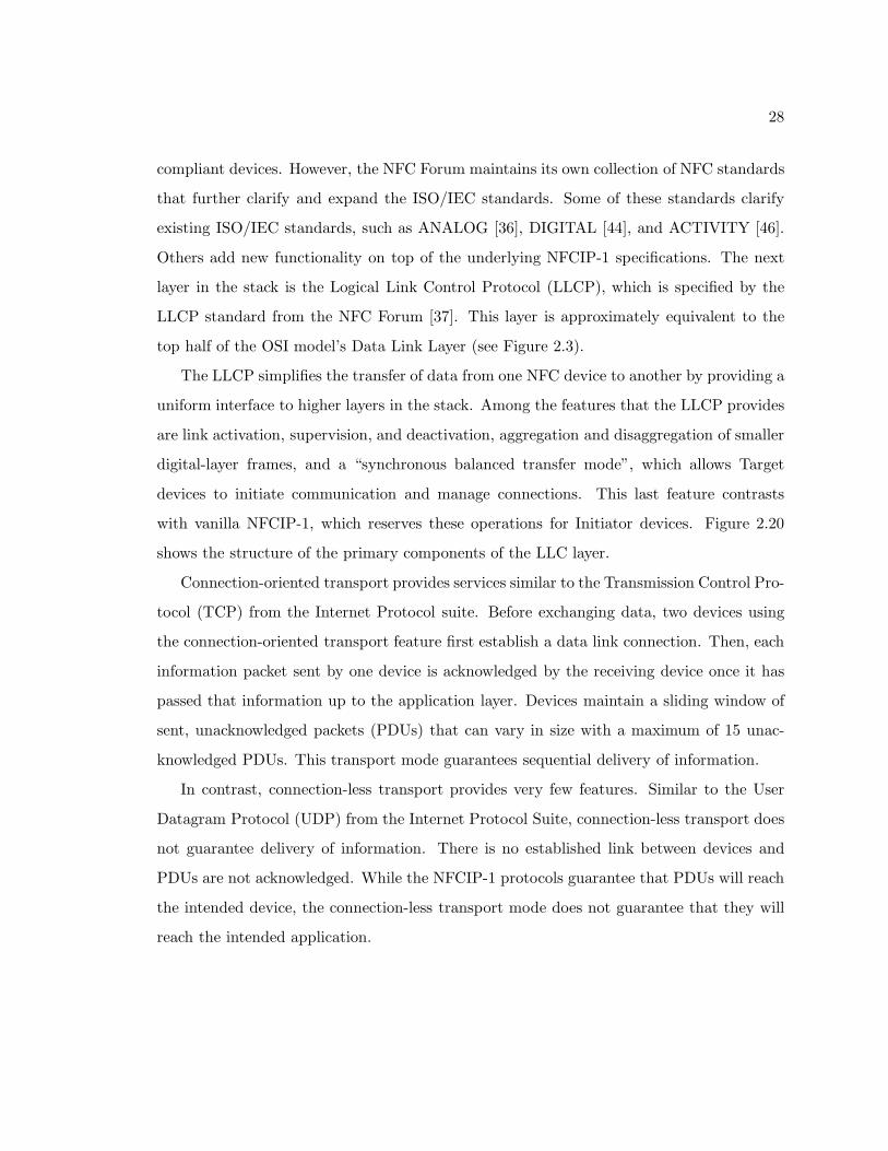
with vanilla NFCIP-1, which reserves these operations for Initiator devices. Figure 2.20
shows the structure of the primary components of the LLC layer.
Connection-oriented transport provides services similar to the Transmission Control Pro-
tocol (TCP) from the Internet Protocol suite. Before exchanging data, two devices using
the connection-oriented transport feature first establish a data link connection. Then, each
information packet sent by one device is acknowledged by the receiving device once it has
passed that information up to the application layer. Devices maintain a sliding window of
sent, unacknowledged packets (PDUs) that can vary in size with a maximum of 15 unac-
knowledged PDUs. This transport mode guarantees sequential delivery of information.
In contrast, connection-less transport provides very few features. Similar to the User
Datagram Protocol (UDP) from the Internet Protocol Suite, connection-less transport does
not guarantee delivery of information. There is no established link between devices and
PDUs are not acknowledged. While the NFCIP-1 protocols guarantee that PDUs will reach
the intended device, the connection-less transport mode does not guarantee that they will
reach the intended application.
29
Figure 2.20: Structure of the LLC layer. The MAC mapping sublayer allows the LLC tointerface with various other digital interfaces, but this text only considers those NFC devicesusing the NFC-DEP protocol [37].
2.3.3.1 LLCP Frames
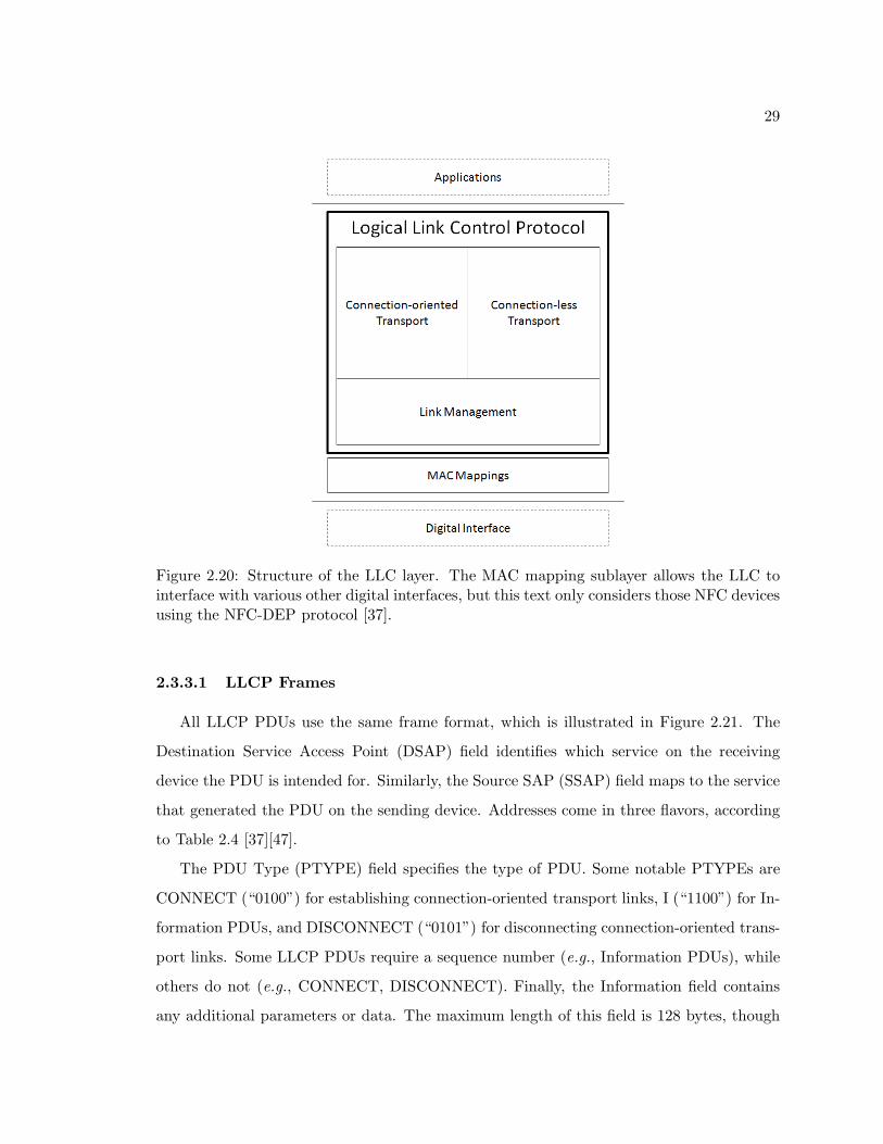
All LLCP PDUs use the same frame format, which is illustrated in Figure 2.21. The
Destination Service Access Point (DSAP) field identifies which service on the receiving
device the PDU is intended for. Similarly, the Source SAP (SSAP) field maps to the service
that generated the PDU on the sending device. Addresses come in three flavors, according
to Table 2.4 [37][47].
The PDU Type (PTYPE) field specifies the type of PDU. Some notable PTYPEs are
CONNECT (“0100”) for establishing connection-oriented transport links, I (“1100”) for In-
formation PDUs, and DISCONNECT (“0101”) for disconnecting connection-oriented trans-
port links. Some LLCP PDUs require a sequence number (e.g., Information PDUs), while
others do not (e.g., CONNECT, DISCONNECT). Finally, the Information field contains
any additional parameters or data. The maximum length of this field is 128 bytes, though
30
Table 2.4: Service Access Point Address Mapping for LLCP.
SAP Description
00h–0Fh Well-Known Service Access Points
00h · · · LLCP Link Management
01h · · · Service Discovery Protocol (SDP)
04h · · · Simple NDEF Exchange Protocol (SNEP)
10h–1Fh Services in the local service environment that are advertised by SDP
20h–3Fh Services in the local service environment that are not advertised by SDP
Figure 2.21: Format of the LLCP PDU. The value of M is 0–128 by default, though devicescan specify a larger maximum upon link establishment. Not all PDUs have the Sequencefield [37].
devices can establish a higher maximum when establishing a link.
2.3.3.2 MAC Mapping
The LLC layer can support different MAC mappings. However, the NFC Forum only
specifies the NFC-DEP mapping. This mapping sits atop the Digital Interface described in
Section 2.3.2, but with the following notable restrictions [37]:
• The Device ID (DID) feature is not used.
• The NAD feature is not used.
• Timeout Extension PDUs are not used.
• The Attention PDU is used only for exceptions.
31
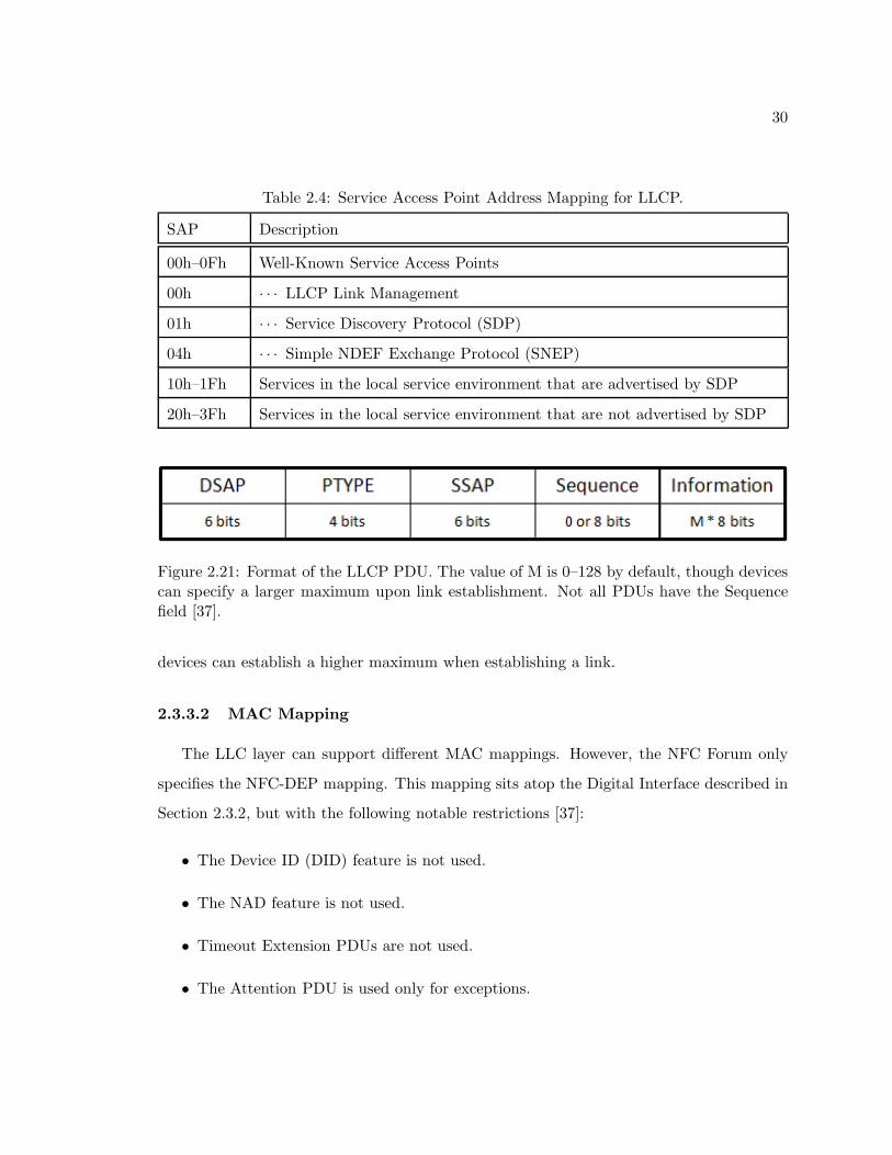
Figure 2.22: Example of an ATR REQ that supports LLCP. This device uses version 1.1of LLCP, keeps the default MIU of 128, supports the LLC Protocol and the Simple NDEFExchange Protocol (see Section 2.3.4), keeps the default LTO of 100 ms, and supports bothconnection-oriented and connection-less transport modes.
• The payload length value for ATR REQ and similar commands is always set to “11”
for a maximum length of 255 bytes.
2.3.3.3 Activating a Link
In order to activate the LLC protocol, the MAC sets the first three General Bytes of
ATR REQ (G(1)–G(3)) to “46h 66h 6Dh”. Following this, the MAC writes a number of
additional LLC-related parameters into the General Bytes field. Table 2.5 [37] describes the
parameters, called TLVs (type, length, value), and Figure 2.22 shows an example ATR REQ
frame with support for LLCP. Only the VERSION TLV is mandatory and only the TLVs
included in Table 2.5 are supported.
Once the Target device receives the LLCP-enabled ATR REQ, it issues an ATR RES
with the same format for the General Bytes field. Then, both devices continue the normal
NFC-DEP activation algorithm, including parameter selections. When both devices enter
the DEP stage, they notify their local LLC layers that a connection is complete. At this
point, the LLC layer takes over.
The LLC layers must agree on a protocol version number before proceeding. If the
major and minor version numbers for both the ATR REQ and the ATR RES match, then
the version number is that of the ATR REQ. If the major numbers match, but the minors
do not, then the version number is the lower of the two. If the major numbers do not
match, then the device with the higher major number determines if the other device’s
version number is compatible. If so, then both devices use the lower version number. If
not, then the link activation fails.
32
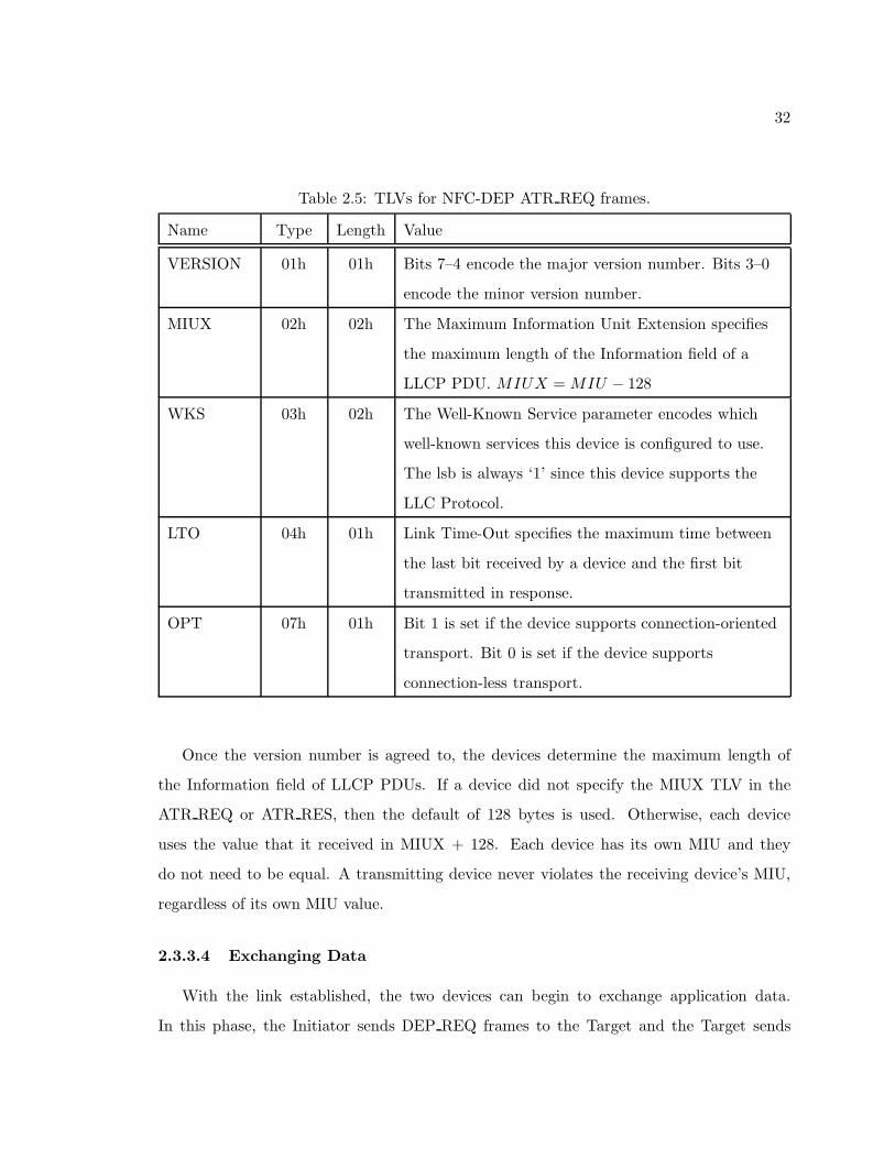
Table 2.5: TLVs for NFC-DEP ATR REQ frames.
Name Type Length Value
VERSION 01h 01h Bits 7–4 encode the major version number. Bits 3–0
encode the minor version number.
MIUX 02h 02h The Maximum Information Unit Extension specifies
the maximum length of the Information field of a
LLCP PDU. MIUX =MIU − 128
WKS 03h 02h The Well-Known Service parameter encodes which
well-known services this device is configured to use.
The lsb is always ‘1’ since this device supports the
LLC Protocol.
LTO 04h 01h Link Time-Out specifies the maximum time between
the last bit received by a device and the first bit
transmitted in response.
OPT 07h 01h Bit 1 is set if the device supports connection-oriented
transport. Bit 0 is set if the device supports
connection-less transport.
Once the version number is agreed to, the devices determine the maximum length of
the Information field of LLCP PDUs. If a device did not specify the MIUX TLV in the
ATR REQ or ATR RES, then the default of 128 bytes is used. Otherwise, each device
uses the value that it received in MIUX + 128. Each device has its own MIU and they
do not need to be equal. A transmitting device never violates the receiving device’s MIU,
regardless of its own MIU value.
2.3.3.4 Exchanging Data
With the link established, the two devices can begin to exchange application data.
In this phase, the Initiator sends DEP REQ frames to the Target and the Target sends
33
DEP RES frames to the Initiator. When a LLCP PDU does not fit into a single DEP
frame, the Multiple Information chaining mechanism described in Section 2.3.2.2 is used.
When receiving chained data, the MAC reassembles it into a single LLCP PDU before
passing it up to the LLC layer. During the date exchange phase, either the connection-less
transport mode or the connection-oriented transport mode can be used.
Connection-less Transport — The connection-less transport mode does not require
the establishment of a data link and thus also does not require the disconnection of such
a link. In this mode, all information is sent with the Unnumbered Information (UI) PDU,
which does not use a sequence number. Both devices are able to send and received UI
PDUs at any time, within the limits of the NFC-DEP protocol, and neither device ever
acknowledges receipt of a UI PDU from the other device. Both devices are free to ignore
incoming PDUs for any reason.
Connection-oriented Transport — In contrast to connection-less mode, the connection-
oriented transport mode does require establishing a logical data link before exchanging other
data. A device can request to establish a data link with the CONNECT PDU, which spec-
ifies the MIUX to use for the connection, the receive window size, and the name of the
service on the remote device to which the local device wishes to establish a data link. The
remote device responds with a Connection Complete (CC) PDU, which specifies the MIUX
and receive window size for the remove device.
With the data link established, the two devices can now exchange data using Information
(I) PDUs. These PDUs use a sequence number to ensure that the receiving device receives
them in the correct order. Each I PDU must be acknowledged by the receiving device with
a Receive Ready (RR) PDU. If the receiver is not ready for the next I PDU, it instead sends
the Receive Not Ready (RNR) PDU. When it later becomes ready, it then sends the RR
PDU. If there is a problem with a received I PDU, then the receiver can reply with a Frame
Reject (FRMR) PDU to inform the sending device of the problem and the sending device
can choose to resend the errored frame. Using this protocol, both devices can be sure that
each frame is sent and received in the proper order and without error.
34
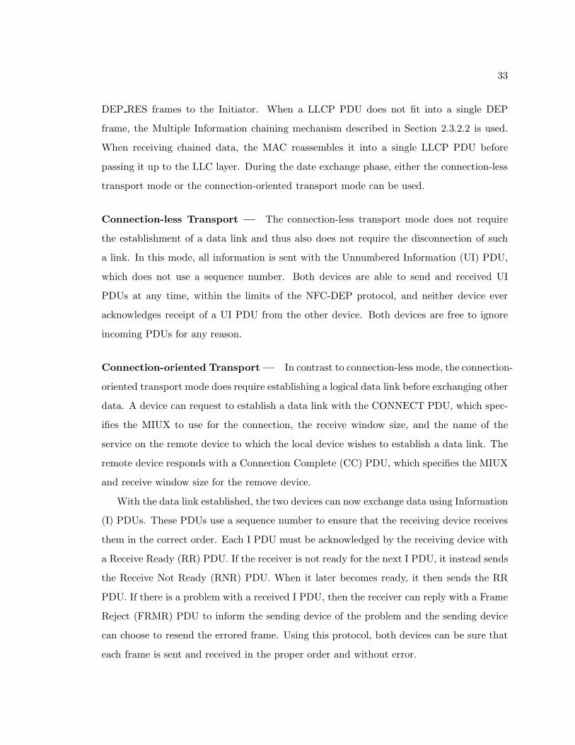
Figure 2.23: Simple NDEF Exchange Protocol (SNEP) frame format. The upper nibble ofVersion encode the major version number while the lower nibble encodes the minor versionnumber. The Code is a request code for frames sent by a SNEP client and a response codefor frames send by a SNEP server. Not all frames have the Information field [48].
When a device wishes to terminate a data link, it sends the Disconnect (DISC) PDU
with the DSAP field populated with the access point of the service to disconnect from. In
response, the remote device informs the application-layer service of the disconnection and
then issues the Disconnect Mode (DM) PDU to confirm the data link disconnection.
2.3.3.5 Deactivating a Link
To terminate the LLC link connection, a device issues the DISC PDU with the DSAP set
to 00h to indicate the LLCP service. The other device responds with the DM PDU. Once
this is complete, the LLC layers inform their respective MAC layers to disconnect. The
Initiator sends the DSL REQ frame, which the Target answers with the DSL RES frame.
This completes both the NFC-DEP and LLC protocols.
2.3.4 Simple NDEF Exchange Protocol
The Simple NDEF Exchange Protocol (SNEP), defined by the NFC Forum’s SNEP
specification [48] sits atop the LLC layer and acts as a service that allows two NFC Forum
devices to exchange NFC Data Exchange Format (NDEF) messages (see Section 2.3.5). The
SNEP service is found at SAP 04h [47]. SNEP frames are transmitted in the Information
field of LLCP PDUs and have the format shown in Figure 2.23. The largest NDEF message
that can fit into a SNEP frame is 232 − 1 bytes because this is the largest value that fits
into the 32-bit Length field.
When a SNEP message does not fit into a single LLCP PDU, it is split into multiple
PDUs. Upon receiving the first PDU, the receiving device checks the protocol version
number of the received frame using an algorithm similar to the one used by the LLC
Protocol. If the received protocol version is supported, then the receiving device can send
35
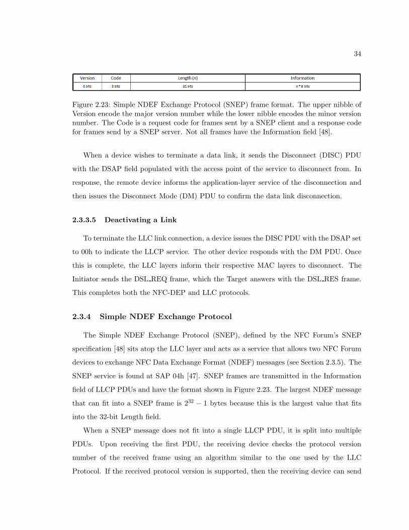
Figure 2.24: Example of a fragmented SNEP message. The web server sends a URL encodedas a NDEF message to the SNEP client, which sends a “Get” request to the SNEP server.The SNEP server passes the URL to the web server, which retrieves the document andpasses it to the SNEP server as a NDEF message. Since the document is too large to fitinto one SNEP message, the SNEP server splits it into four fragments. Once the SNEPclient has received all four fragments, it passes the NDEF document back to the web browser[48].
a “Continue” frame, which prompts the sending device to send the remaining pieces of the
SNEP message. If the protocol version is not supported, then the receiving device sends a
“Unsupported Version” frame and the transaction is complete. Figure 2.24 illustrates an
example in which the SNEP client requests a message from a SNEP server and the SNEP
server’s response does not fit into a single SNEP frame.
There are four request codes that the SNEP client can send to a SNEP server, which
are summarized in Table 2.6 [48]. The “Continue” request code asks the SNEP server to
send the remaining fragments of a fragmented SNEP message. The Information field of
a “Continue” request is empty and so the Length field is zero. If the client is unable or
unwilling to receive the remaining fragments, then it instead sends a “Reject” request. This
request also contains an empty Information field.
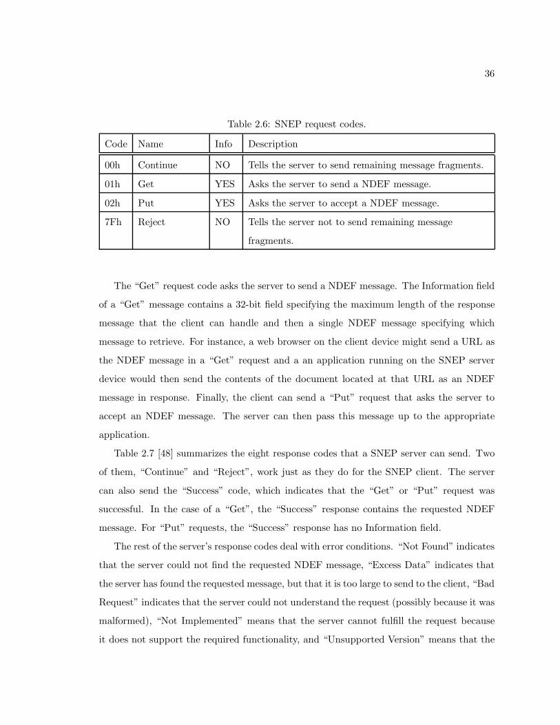
36
Table 2.6: SNEP request codes.
Code Name Info Description
00h Continue NO Tells the server to send remaining message fragments.
01h Get YES Asks the server to send a NDEF message.
02h Put YES Asks the server to accept a NDEF message.
7Fh Reject NO Tells the server not to send remaining message
fragments.
The “Get” request code asks the server to send a NDEF message. The Information field
of a “Get” message contains a 32-bit field specifying the maximum length of the response
message that the client can handle and then a single NDEF message specifying which
message to retrieve. For instance, a web browser on the client device might send a URL as
the NDEF message in a “Get” request and a an application running on the SNEP server
device would then send the contents of the document located at that URL as an NDEF
message in response. Finally, the client can send a “Put” request that asks the server to
accept an NDEF message. The server can then pass this message up to the appropriate
application.
Table 2.7 [48] summarizes the eight response codes that a SNEP server can send. Two
of them, “Continue” and “Reject”, work just as they do for the SNEP client. The server
can also send the “Success” code, which indicates that the “Get” or “Put” request was
successful. In the case of a “Get”, the “Success” response contains the requested NDEF
message. For “Put” requests, the “Success” response has no Information field.
The rest of the server’s response codes deal with error conditions. “Not Found” indicates
that the server could not find the requested NDEF message, “Excess Data” indicates that
the server has found the requested message, but that it is too large to send to the client, “Bad
Request” indicates that the server could not understand the request (possibly because it was
malformed), “Not Implemented” means that the server cannot fulfill the request because
it does not support the required functionality, and “Unsupported Version” means that the
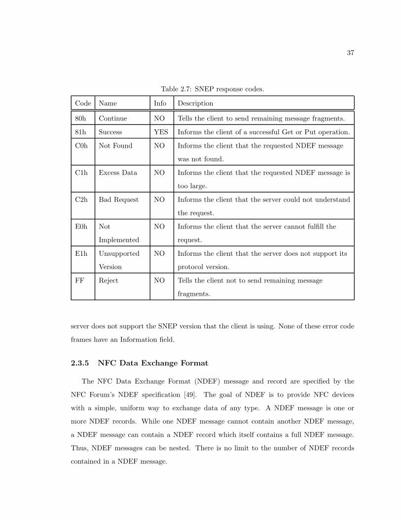
37
Table 2.7: SNEP response codes.
Code Name Info Description
80h Continue NO Tells the client to send remaining message fragments.
81h Success YES Informs the client of a successful Get or Put operation.
C0h Not Found NO Informs the client that the requested NDEF message
was not found.
C1h Excess Data NO Informs the client that the requested NDEF message is
too large.
C2h Bad Request NO Informs the client that the server could not understand
the request.
E0h Not
Implemented
NO Informs the client that the server cannot fulfill the
request.
E1h Unsupported
Version
NO Informs the client that the server does not support its
protocol version.
FF Reject NO Tells the client not to send remaining message
fragments.
server does not support the SNEP version that the client is using. None of these error code
frames have an Information field.
2.3.5 NFC Data Exchange Format
The NFC Data Exchange Format (NDEF) message and record are specified by the
NFC Forum’s NDEF specification [49]. The goal of NDEF is to provide NFC devices
with a simple, uniform way to exchange data of any type. A NDEF message is one or
more NDEF records. While one NDEF message cannot contain another NDEF message,
a NDEF message can contain a NDEF record which itself contains a full NDEF message.
Thus, NDEF messages can be nested. There is no limit to the number of NDEF records
contained in a NDEF message.

38
Figure 2.25: Format of an NDEF record. The fields with italicized labels have variablelengths. The size of the Type, ID, and Payload fields are encoded in the Type Length,Payload Length, and ID Length fields, respectively. If the IL flag is not set, then neitherthe ID Length field nor the ID field is included in the record. If the Type Length or PayloadLength is zero, then the respective Type or Payload field is not present in the record [49].
Figure 2.25 show the format of a NDEF record. The Message Begin (MB) flag is set for
the first NDEF record in a NDEF message and the Message End (ME) flag is set for the
final NDEF record in a NDEF message. If the message has only one record, then both flags
are set. The Chunk Flag (CF) flag indicates that a record is either the first chunk or an
intermediate chunk of a chunked payload. The final chunk of a chunked payload does not
set CF. The Short Record (SR) flag indicates that this NDEF record is of the short record
format (see Figure 2.26). Finally, the ID Length (IL) flag is set when the ID Length field is
present in the record. The Type Name Format (TNF) field encodes the format of the Type
field.
The maximum length of the payload in a normal NDEF record is 232 − 1 bytes because
the Payload Length field is 32 bits. Longer application payloads can be separated into
chunks using the chunked payload feature. The full payload must be contained in a single
NDEF message, which has no limit on size. Chunked payloads have an initial record, zero or
more intermediate records, and a final record. The initial record of a chunked payload also
specifies the payload type and (optionally) the ID for the entire set. Subsequent records set
39
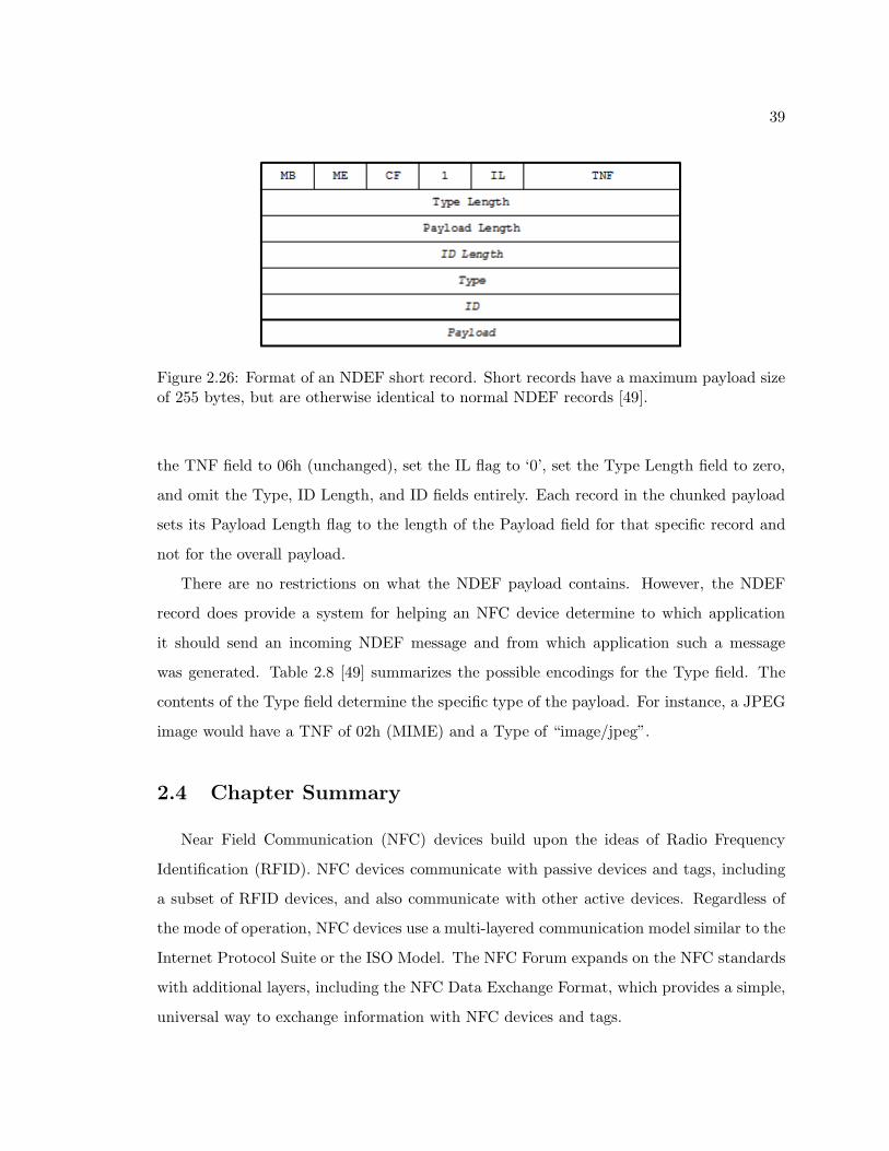
Figure 2.26: Format of an NDEF short record. Short records have a maximum payload sizeof 255 bytes, but are otherwise identical to normal NDEF records [49].
the TNF field to 06h (unchanged), set the IL flag to ‘0’, set the Type Length field to zero,
and omit the Type, ID Length, and ID fields entirely. Each record in the chunked payload
sets its Payload Length flag to the length of the Payload field for that specific record and
not for the overall payload.
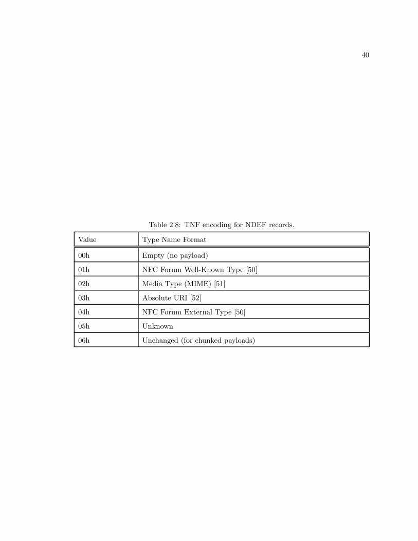
There are no restrictions on what the NDEF payload contains. However, the NDEF
record does provide a system for helping an NFC device determine to which application
it should send an incoming NDEF message and from which application such a message
was generated. Table 2.8 [49] summarizes the possible encodings for the Type field. The
contents of the Type field determine the specific type of the payload. For instance, a JPEG
image would have a TNF of 02h (MIME) and a Type of “image/jpeg”.
2.4 Chapter Summary
Near Field Communication (NFC) devices build upon the ideas of Radio Frequency
Identification (RFID). NFC devices communicate with passive devices and tags, including
a subset of RFID devices, and also communicate with other active devices. Regardless of
the mode of operation, NFC devices use a multi-layered communication model similar to the
Internet Protocol Suite or the ISO Model. The NFC Forum expands on the NFC standards
with additional layers, including the NFC Data Exchange Format, which provides a simple,
universal way to exchange information with NFC devices and tags.
40
Table 2.8: TNF encoding for NDEF records.
Value Type Name Format
00h Empty (no payload)
01h NFC Forum Well-Known Type [50]
02h Media Type (MIME) [51]
03h Absolute URI [52]
04h NFC Forum External Type [50]
05h Unknown
06h Unchanged (for chunked payloads)
41
Chapter 3
Cryptography Overview
The ECMA-385 [53] standard describes the NFC Security and Services Protocol (NFC-
SEC) and ECMA-386 [54] describes a means of implementing that protocol. This chapter
describes NFC-SEC and the cryptographic algorithms used to implement it.
3.1 Advanced Encryption Standard
The Advanced Encryption Standard (AES) is a method for encrypting electronic data.
In 2001, the National Institute of Standards and Technology (NIST) announced AES as
Federal Information Processing Standards Publication 197 [56]. Since then, AES has been
adopted by the United States government as a replacement for the Data Encryption Stan-
dard (DES), and the National Security Agency approved the use of AES for encrypting
SECRET and TOP SECRET classified information [57]. Many modern computer proces-
sors have special instructions for quickly encrypting data with AES [58] and many software
libraries take advantage of these special instructions, including the popular OpenSSL secu-
rity suite [59]. In summary, AES is a powerful, widely-used encryption algorithm.
The input to AES is a message, called the plaintext, and the output is an encrypted
message, called the ciphertext. At a high level, AES uses a secret number, called the
cipher key, to perform mathematical operations on the bits that make up the plaintext.
AES supports key sizes or 128, 192, and 256 bits. The NFC-SEC protocol uses a key size of
Parts of this Chapter were submitted for publication to Elsevier Computer Communications [55].
42
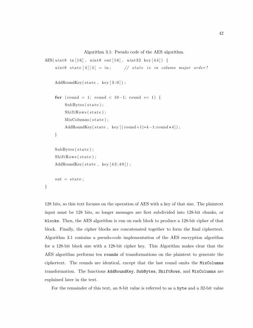
Algorithm 3.1: Pseudo code of the AES algorithm.
AES( uint8 in [ 1 6 ] , u int8 out [ 1 6 ] , u int32 key [ 4 4 ] ) {
uint8 s t a t e [ 4 ] [ 4 ] = in ; // s t a t e i s in column major order !
AddRoundKey( s tate , key [ 3 : 0 ] ) ;
for ( round = 1 ; round < 10−1; round += 1) {
SubBytes ( s t a t e ) ;
ShiftRows ( s t a t e ) ;
MixColumns ( s t a t e ) ;
AddRoundKey( s tate , key [ ( round+1)*4−1: round *4 ] ) ;
}
SubBytes ( s t a t e ) ;
ShiftRows ( s t a t e ) ;
AddRoundKey( s tate , key [ 4 3 : 4 0 ] ) ;
out = s t a t e ;
}
128 bits, so this text focuses on the operation of AES with a key of that size. The plaintext
input must be 128 bits, so longer messages are first subdivided into 128-bit chunks, or
blocks. Then, the AES algorithm is run on each block to produce a 128-bit cipher of that
block. Finally, the cipher blocks are concatenated together to form the final ciphertext.
Algorithm 3.1 contains a pseudo-code implementation of the AES encryption algorithm
for a 128-bit block size with a 128-bit cipher key. This Algorithm makes clear that the
AES algorithm performs ten rounds of transformations on the plaintext to generate the
ciphertext. The rounds are identical, except that the last round omits the MixColumns
transformation. The functions AddRoundKey, SubBytes, ShiftRows, and MixColumns are
explained later in the text.
For the remainder of this text, an 8-bit value is referred to as a byte and a 32-bit value
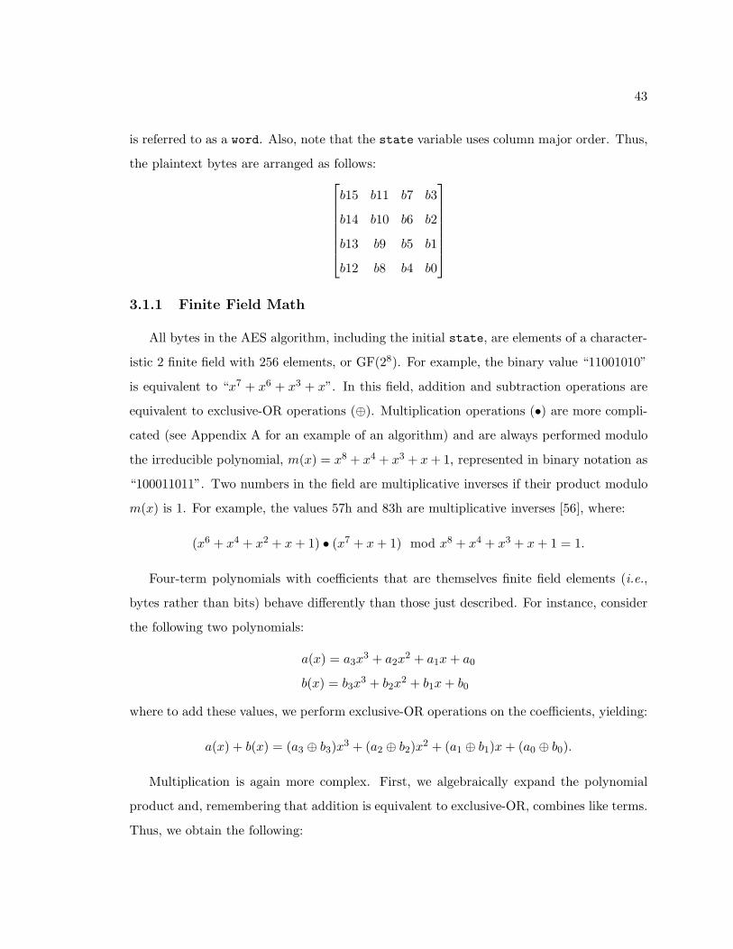
43
is referred to as a word. Also, note that the state variable uses column major order. Thus,
the plaintext bytes are arranged as follows:
b15 b11 b7 b3
b14 b10 b6 b2
b13 b9 b5 b1
b12 b8 b4 b0
3.1.1 Finite Field Math
All bytes in the AES algorithm, including the initial state, are elements of a character-
istic 2 finite field with 256 elements, or GF(28). For example, the binary value “11001010”
is equivalent to “x7 + x6 + x3 + x”. In this field, addition and subtraction operations are
equivalent to exclusive-OR operations (⊕). Multiplication operations (•) are more compli-
cated (see Appendix A for an example of an algorithm) and are always performed modulo
the irreducible polynomial, m(x) = x8 + x4 + x3 + x+ 1, represented in binary notation as
“100011011”. Two numbers in the field are multiplicative inverses if their product modulo
m(x) is 1. For example, the values 57h and 83h are multiplicative inverses [56], where:
(x6 + x4 + x2 + x+ 1) • (x7 + x+ 1) mod x8 + x4 + x3 + x+ 1 = 1.
Four-term polynomials with coefficients that are themselves finite field elements (i.e.,
bytes rather than bits) behave differently than those just described. For instance, consider
the following two polynomials:
a(x) = a3x3 + a2x
2 + a1x+ a0
b(x) = b3x3 + b2x
2 + b1x+ b0
where to add these values, we perform exclusive-OR operations on the coefficients, yielding:
a(x) + b(x) = (a3 ⊕ b3)x3 + (a2 ⊕ b2)x
2 + (a1 ⊕ b1)x+ (a0 ⊕ b0).
Multiplication is again more complex. First, we algebraically expand the polynomial
product and, remembering that addition is equivalent to exclusive-OR, combines like terms.
Thus, we obtain the following:
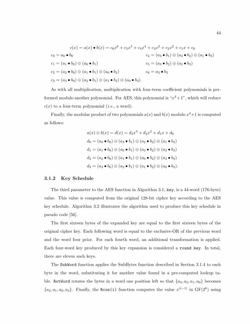
44
c(x) = a(x) • b(x) = c6x6 + c5x
5 + c4x4 + c3x
3 + c2x2 + c1x+ c0
c0 = a0 • b0 c4 = (a3 • b1)⊕ (a2 • b2)⊕ (a1 • b3)
c1 = (a1 • b0)⊕ (a0 • b1) c5 = (a3 • b2)⊕ (a2 • b3)
c2 = (a2 • b0)⊕ (a1 • b1)⊕ (a0 • b2) c6 = a3 • b3
c3 = (a3 • b0)⊕ (a2 • b1)⊕ (a1 • b2)⊕ (a0 • b3).
As with all multiplication, multiplication with four-term coefficient polynomials is per-
formed modulo another polynomial. For AES, this polynomial is “x4+1”, which will reduce
c(x) to a four-term polynomial (i.e., a word).
Finally, the modular product of two polynomials a(x) and b(x) modulo x4+1 is computed
as follows:
a(x)⊗ b(x) = d(x) = d3x3 + d2x
2 + d1x+ d0
d0 = (a0 • b0)⊕ (a3 • b1)⊕ (a2 • b2)⊕ (a1 • b3)
d1 = (a1 • b0)⊕ (a0 • b1)⊕ (a3 • b2)⊕ (a2 • b3)
d2 = (a2 • b0)⊕ (a1 • b1)⊕ (a0 • b2)⊕ (a3 • b3)
d3 = (a3 • b0)⊕ (a2 • b1)⊕ (a1 • b2)⊕ (a0 • b3).
3.1.2 Key Schedule
The third parameter to the AES function in Algorithm 3.1, key, is a 44-word (176-byte)
value. This value is computed from the original 128-bit cipher key according to the AES
key schedule. Algorithm 3.2 illustrates the algorithm used to produce this key schedule in
pseudo code [56].
The first sixteen bytes of the expanded key are equal to the first sixteen bytes of the
original cipher key. Each following word is equal to the exclusive-OR of the previous word
and the word four prior. For each fourth word, an additional transformation is applied.
Each four-word key produced by this key expansion is considered a round key. In total,
there are eleven such keys.
The SubWord function applies the SubBytes function described in Section 3.1.4 to each
byte in the word, substituting it for another value found in a pre-computed lookup ta-
ble. RotWord rotates the bytes in a word one position left so that {a3, a2, a1, a0} becomes
{a2, a1, a0, a3}. Finally, the Rcon(i) function computes the value x(i−1) in GF(28) using
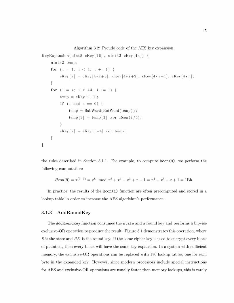
45
Algorithm 3.2: Pseudo code of the AES key expansion.
KeyExpansion( u int8 cKey [ 1 6 ] , u int32 eKey [ 4 4 ] ) {
uint32 temp ;
for ( i = 1 ; i < 4 ; i += 1) {
eKey [ i ] = cKey [4* i +3] , cKey [4* i +2] , cKey [4* i +1] , cKey [4* i ] ;
}
for ( i = 4 ; i < 44 ; i += 1) {
temp = eKey [ i −1] ;
i f ( i mod 4 == 0) {
temp = SubWord(RotWord( temp) ) ;
temp [ 3 ] = temp [ 3 ] xor Rcon( i /4) ;
}
eKey [ i ] = eKey [ i −4] xor temp ;
}
}
the rules described in Section 3.1.1. For example, to compute Rcon(9), we perform the
following computation:
Rcon(9) = x(9−1) = x8 mod x8 + x4 + x3 + x+ 1 = x4 + x3 + x+ 1 = 1Bh.
In practice, the results of the Rcon(i) function are often precomputed and stored in a
lookup table in order to increase the AES algorithm’s performance.
3.1.3 AddRoundKey
The AddRoundKey function consumes the state and a round key and performs a bitwise
exclusive-OR operation to produce the result. Figure 3.1 demonstrates this operation, where
S is the state and RK is the round key. If the same cipher key is used to encrypt every block
of plaintext, then every block will have the same key expansion. In a system with sufficient
memory, the exclusive-OR operations can be replaced with 176 lookup tables, one for each
byte in the expanded key. However, since modern processors include special instructions
for AES and exclusive-OR operations are usually faster than memory lookups, this is rarely
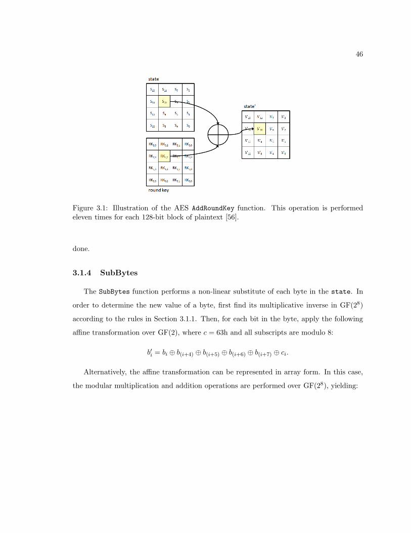
46
Figure 3.1: Illustration of the AES AddRoundKey function. This operation is performedeleven times for each 128-bit block of plaintext [56].
done.
3.1.4 SubBytes
The SubBytes function performs a non-linear substitute of each byte in the state. In
order to determine the new value of a byte, first find its multiplicative inverse in GF(28)
according to the rules in Section 3.1.1. Then, for each bit in the byte, apply the following
affine transformation over GF(2), where c = 63h and all subscripts are modulo 8:
b′i = bi ⊕ b(i+4) ⊕ b(i+5) ⊕ b(i+6) ⊕ b(i+7) ⊕ ci.
Alternatively, the affine transformation can be represented in array form. In this case,
the modular multiplication and addition operations are performed over GF(28), yielding:
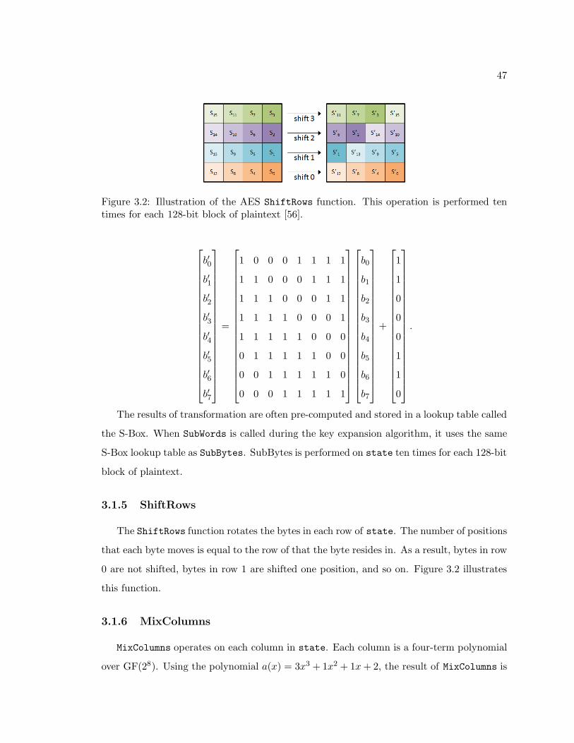
47
Figure 3.2: Illustration of the AES ShiftRows function. This operation is performed tentimes for each 128-bit block of plaintext [56].
b′0
b′1
b′2
b′3
b′4
b′5
b′6
b′7
=
1 0 0 0 1 1 1 1
1 1 0 0 0 1 1 1
1 1 1 0 0 0 1 1
1 1 1 1 0 0 0 1
1 1 1 1 1 0 0 0
0 1 1 1 1 1 0 0
0 0 1 1 1 1 1 0
0 0 0 1 1 1 1 1
b0
b1
b2
b3
b4
b5
b6
b7
+
1
1
0
0
0
1
1
0
.
The results of transformation are often pre-computed and stored in a lookup table called
the S-Box. When SubWords is called during the key expansion algorithm, it uses the same
S-Box lookup table as SubBytes. SubBytes is performed on state ten times for each 128-bit
block of plaintext.
3.1.5 ShiftRows
The ShiftRows function rotates the bytes in each row of state. The number of positions
that each byte moves is equal to the row of that the byte resides in. As a result, bytes in row
0 are not shifted, bytes in row 1 are shifted one position, and so on. Figure 3.2 illustrates
this function.
3.1.6 MixColumns
MixColumns operates on each column in state. Each column is a four-term polynomial
over GF(28). Using the polynomial a(x) = 3x3 + 1x2 + 1x+ 2, the result of MixColumns is
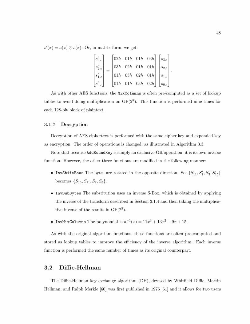
48
s′(x) = a(x)⊗ s(x). Or, in matrix form, we get:
s′3,c
s′2,c
s′1,c
s′0,c
=
02h 01h 01h 03h
03h 02h 01h 01h
01h 03h 02h 01h
01h 01h 03h 02h
s3,c
s2,c
s1,c
s0,c
.
As with other AES functions, the MixColumns is often pre-computed as a set of lookup
tables to avoid doing multiplication on GF(28). This function is performed nine times for
each 128-bit block of plaintext.
3.1.7 Decryption
Decryption of AES ciphertext is performed with the same cipher key and expanded key
as encryption. The order of operations is changed, as illustrated in Algorithm 3.3.
Note that because AddRoundKey is simply an exclusive-OR operation, it is its own inverse
function. However, the other three functions are modified in the following manner:
• InvShiftRows The bytes are rotated in the opposite direction. So, {S′11, S
′7, S
′3, S
′15}
becomes {S15, S11, S7, S3}.
• InvSubBytes The substitution uses an inverse S-Box, which is obtained by applying
the inverse of the transform described in Section 3.1.4 and then taking the multiplica-
tive inverse of the results in GF(28).
• InvMixColumns The polynomial is a−1(x) = 11x3 + 13x2 + 9x+ 15.
As with the original algorithm functions, these functions are often pre-computed and
stored as lookup tables to improve the efficiency of the inverse algorithm. Each inverse
function is performed the same number of times as its original counterpart.
3.2 Diffie-Hellman
The Diffie-Hellman key exchange algorithm (DH), devised by Whitfield Diffie, Martin
Hellman, and Ralph Merkle [60] was first published in 1976 [61] and it allows for two users
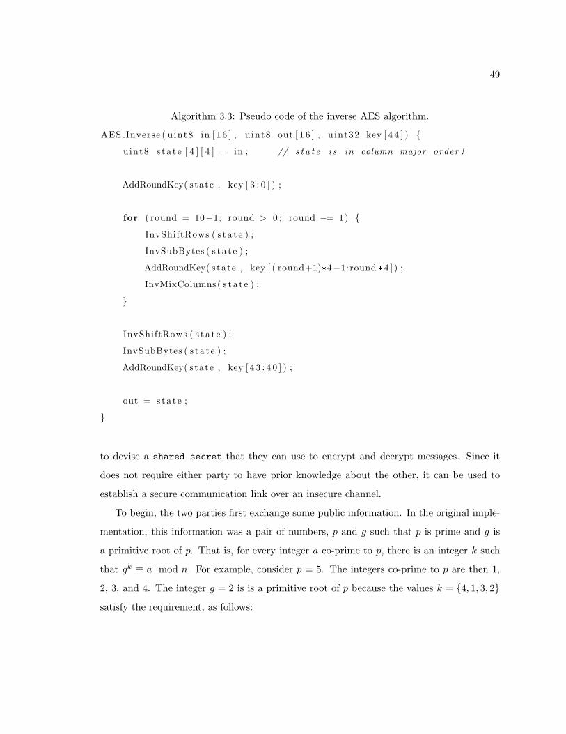
49
Algorithm 3.3: Pseudo code of the inverse AES algorithm.
AES Inverse ( u int8 in [ 1 6 ] , u int8 out [ 1 6 ] , u int32 key [ 4 4 ] ) {
uint8 s t a t e [ 4 ] [ 4 ] = in ; // s t a t e i s in column major order !
AddRoundKey( s tate , key [ 3 : 0 ] ) ;
for ( round = 10−1; round > 0 ; round −= 1) {
InvShiftRows ( s t a t e ) ;
InvSubBytes ( s t a t e ) ;
AddRoundKey( s tate , key [ ( round+1)*4−1: round *4 ] ) ;
InvMixColumns( s t a t e ) ;
}
InvShiftRows ( s t a t e ) ;
InvSubBytes ( s t a t e ) ;
AddRoundKey( s tate , key [ 4 3 : 4 0 ] ) ;
out = s t a t e ;
}
to devise a shared secret that they can use to encrypt and decrypt messages. Since it
does not require either party to have prior knowledge about the other, it can be used to
establish a secure communication link over an insecure channel.
To begin, the two parties first exchange some public information. In the original imple-
mentation, this information was a pair of numbers, p and g such that p is prime and g is
a primitive root of p. That is, for every integer a co-prime to p, there is an integer k such
that gk ≡ a mod n. For example, consider p = 5. The integers co-prime to p are then 1,
2, 3, and 4. The integer g = 2 is is a primitive root of p because the values k = {4, 1, 3, 2}
satisfy the requirement, as follows:
50
24 = 16 = 1 mod 5
21 = 2 = 2 mod 5
23 = 8 = 3 mod 5
22 = 4 = 4 mod 5.
All arithmetic is performed modulo p, forming a finite cyclic group with g as the gener-
ating element. Once the two parties agree on the initial parameters, the first party, Alice,
chooses a random integer, a, and calculates A = ga mod p. Alice sends this new value, A,
to the second party, Bob. Similarly, Bob chooses a random integer, b, and calculates B = gb
mod p, which he sends to Alice. Finally, both parties compute the shared secret, s, using
the following operations:
Alice: s = Ba mod p
Bob: s = Ab mod p.
Note that the shared secret s is equal for both Alice and Bob because (ga)b mod p ≡
(gb)a mod p. When Alice wishes to send a message m to Bob, she multiplies the message
by the shared secret and sends ms. To decrypt it, Bob calculates s−1 and then applies
it to recover the received message, m = mss−1. When Bob sends a message to Alice,
the operations are reversed. Figure 3.3 shows a simple example of the DH key exchange
algorithm.
In practice, the values for a, b, and p would need to be much larger. This is due to
the fact that for large values, there is no efficient algorithm to recover a or b given only
p, g, A, and B, a problem known as the discrete logarithm problem. In addition, while
the original DH implementation used the same secret to encrypt and decrypt messages for
both, modern implementations use a pair of encryption and decryption keys for each user
to provide additional security. Finally, the public information does not need to be a pair of
integers. Other finite cyclic groups work as well. NFC-SEC uses a popular variation of DH
in which the public information are the parameters to an elliptic curve.
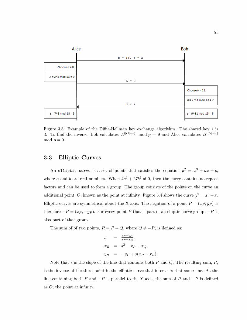
51
Figure 3.3: Example of the Diffie-Hellman key exchange algorithm. The shared key s is3. To find the inverse, Bob calculates A(|G|−b) mod p = 9 and Alice calculates B(|G|−a)
mod p = 9.
3.3 Elliptic Curves
An elliptic curve is a set of points that satisfies the equation y2 = x3 + ax + b,
where a and b are real numbers. When 4a3 + 27b2 6= 0, then the curve contains no repeat
factors and can be used to form a group. The group consists of the points on the curve an
additional point, O, known as the point at infinity. Figure 3.4 shows the curve y2 = x3+x.
Elliptic curves are symmetrical about the X axis. The negation of a point P = (xP , yP ) is
therefore −P = (xP ,−yP ). For every point P that is part of an elliptic curve group, −P is
also part of that group.
The sum of of two points, R = P +Q, where Q 6= −P , is defined as:
s =yP−yQxP−xQ
,
xR = s2 − xP − xQ,
yR = −yP + s(xP − xR).
Note that s is the slope of the line that contains both P and Q. The resulting sum, R,
is the inverse of the third point in the elliptic curve that intersects that same line. As the
line containing both P and −P is parallel to the Y axis, the sum of P and −P is defined
as O, the point at infinity.
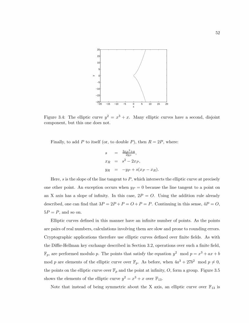
52
x
y
−20 −15 −10 −5 0 5 10 15 20−20
−15
−10
−5
0
5
10
15
20
Figure 3.4: The elliptic curve y2 = x3 + x. Many elliptic curves have a second, disjointcomponent, but this one does not.
Finally, to add P to itself (or, to double P ), then R = 2P , where:
s = 3xP2+a
2yP,
xR = s2 − 2xP ,
yR = −yP + s(xP − xR).
Here, s is the slope of the line tangent to P , which intersects the elliptic curve at precisely
one other point. An exception occurs when yP = 0 because the line tangent to a point on
an X axis has a slope of infinity. In this case, 2P = O. Using the addition rule already
described, one can find that 3P = 2P +P = O+P = P . Continuing in this sense, 4P = O,
5P = P , and so on.
Elliptic curves defined in this manner have an infinite number of points. As the points
are pairs of real numbers, calculations involving them are slow and prone to rounding errors.
Cryptographic applications therefore use elliptic curves defined over finite fields. As with
the Diffie-Hellman key exchange described in Section 3.2, operations over such a finite field,
Fp, are performed modulo p. The points that satisfy the equation y2 mod p = x3 + ax+ b
mod p are elements of the elliptic curve over Fp. As before, when 4a3 + 27b2 mod p 6= 0,
the points on the elliptic curve over Fp and the point at infinity, O, form a group. Figure 3.5
shows the elements of the elliptic curve y2 = x3 + x over F13.
Note that instead of being symmetric about the X axis, an elliptic curve over F13 is
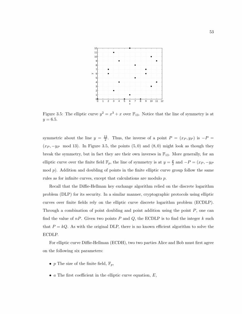
53
0 1 2 3 4 5 6 7 8 9 10 11 120
1
2
3
4
5
6
7
8
9
10
11
12
x
y
Figure 3.5: The elliptic curve y2 = x3 + x over F13. Notice that the line of symmetry is aty = 6.5.
symmetric about the line y = 132 . Thus, the inverse of a point P = (xP , yP ) is −P =
(xP ,−yP mod 13). In Figure 3.5, the points (5, 0) and (8, 0) might look as though they
break the symmetry, but in fact they are their own inverses in F13. More generally, for an
elliptic curve over the finite field Fp, the line of symmetry is at y = p2 and −P = (xP ,−yP
mod p). Addition and doubling of points in the finite elliptic curve group follow the same
rules as for infinite curves, except that calculations are modulo p.
Recall that the Diffie-Hellman key exchange algorithm relied on the discrete logarithm
problem (DLP) for its security. In a similar manner, cryptographic protocols using elliptic
curves over finite fields rely on the elliptic curve discrete logarithm problem (ECDLP).
Through a combination of point doubling and point addition using the point P , one can
find the value of nP . Given two points P and Q, the ECDLP is to find the integer k such
that P = kQ. As with the original DLP, there is no known efficient algorithm to solve the
ECDLP.
For elliptic curve Diffie-Hellman (ECDH), two two parties Alice and Bob must first agree
on the following six parameters:
• p The size of the finite field, Fp,
• a The first coefficient in the elliptic curve equation, E,
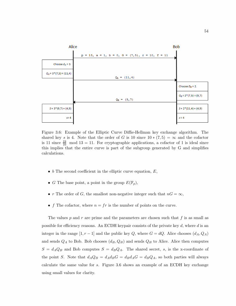
54
Figure 3.6: Example of the Elliptic Curve Diffie-Hellman key exchange algorithm. Theshared key s is 4. Note that the order of G is 10 since 10 ∗ (7, 5) = ∞ and the cofactoris 11 since 19
10 mod 13 = 11. For cryptographic applications, a cofactor of 1 is ideal sincethis implies that the entire curve is part of the subgroup generated by G and simplifiescalculations.
• b The second coefficient in the elliptic curve equation, E,
• G The base point, a point in the group E(Fp),
• r The order of G, the smallest non-negative integer such that nG = ∞,
• f The cofactor, where n = fr is the number of points on the curve.
The values p and r are prime and the parameters are chosen such that f is as small as
possible for efficiency reasons. An ECDH keypair consists of the private key d, where d is an
integer in the range [1, r − 1] and the public key Q, where G = dQ. Alice chooses (dA, QA)
and sends QA to Bob. Bob chooses (dB , QB) and sends QB to Alice. Alice then computes
S = dAQB and Bob computes S = dBQA. The shared secret, s, is the x-coordinate of
the point S. Note that dAQB = dAdBG = dBdAG = dBQA, so both parties will always
calculate the same value for s. Figure 3.6 shows an example of an ECDH key exchange
using small values for clarity.
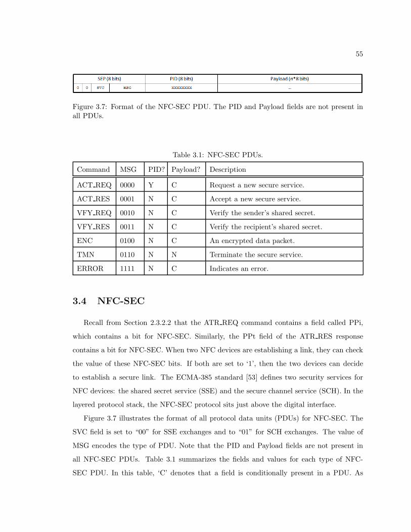
55
Figure 3.7: Format of the NFC-SEC PDU. The PID and Payload fields are not present inall PDUs.
Table 3.1: NFC-SEC PDUs.
Command MSG PID? Payload? Description
ACT REQ 0000 Y C Request a new secure service.
ACT RES 0001 N C Accept a new secure service.
VFY REQ 0010 N C Verify the sender’s shared secret.
VFY RES 0011 N C Verify the recipient’s shared secret.
ENC 0100 N C An encrypted data packet.
TMN 0110 N N Terminate the secure service.
ERROR 1111 N C Indicates an error.
3.4 NFC-SEC
Recall from Section 2.3.2.2 that the ATR REQ command contains a field called PPi,
which contains a bit for NFC-SEC. Similarly, the PPt field of the ATR RES response
contains a bit for NFC-SEC. When two NFC devices are establishing a link, they can check
the value of these NFC-SEC bits. If both are set to ‘1’, then the two devices can decide
to establish a secure link. The ECMA-385 standard [53] defines two security services for
NFC devices: the shared secret service (SSE) and the secure channel service (SCH). In the
layered protocol stack, the NFC-SEC protocol sits just above the digital interface.
Figure 3.7 illustrates the format of all protocol data units (PDUs) for NFC-SEC. The
SVC field is set to “00” for SSE exchanges and to “01” for SCH exchanges. The value of
MSG encodes the type of PDU. Note that the PID and Payload fields are not present in
all NFC-SEC PDUs. Table 3.1 summarizes the fields and values for each type of NFC-
SEC PDU. In this table, ‘C’ denotes that a field is conditionally present in a PDU. As
56
the NFC-SEC protocol sits above the digital layer described by NFCIP-1, the entirety of
each NFC-SEC PDU is transmitted in the Payload field of a NFC PDU during the Data
Exchange Protocol (DEP) phase.
As with other NFC protocols, the PDUs are separated into three phases. In the
first phase, two NFC-SEC devices establish the secure services. The Activation Request
(ACT REQ) and Activation Response (ACT RES) PDUs begin the service. Next, the
Verification Request (VFY REQ) and Verification Response (VFY RES) enable the two
devices to ensure that their shared secret is valid. Once the link is established, encrypted
messages are sent with the Encrypted (ENC) PDU. To terminate the link, one device sends
the Terminate (TMN) PDU. Finally, errors are sent with the ERROR PDU, which always
terminates a secure link. Figure 3.8 shows the process of establishing, using, and then
terminating the secure services described by NFC-SEC.
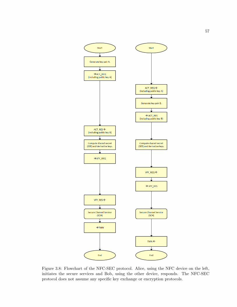
57
Figure 3.8: Flowchart of the NFC-SEC protocol. Alice, using the NFC device on the left,initiates the secure services and Bob, using the other device, responds. The NFC-SECprotocol does not assume any specific key exchange or encryption protocols.
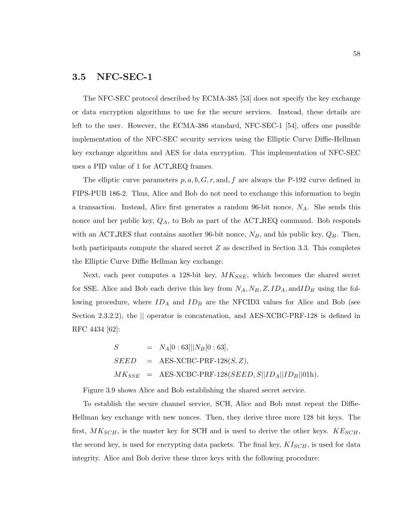
58
3.5 NFC-SEC-1
The NFC-SEC protocol described by ECMA-385 [53] does not specify the key exchange
or data encryption algorithms to use for the secure services. Instead, these details are
left to the user. However, the ECMA-386 standard, NFC-SEC-1 [54], offers one possible
implementation of the NFC-SEC security services using the Elliptic Curve Diffie-Hellman
key exchange algorithm and AES for data encryption. This implementation of NFC-SEC
uses a PID value of 1 for ACT REQ frames.
The elliptic curve parameters p, a, b,G, r, and, f are always the P-192 curve defined in
FIPS-PUB 186-2. Thus, Alice and Bob do not need to exchange this information to begin
a transaction. Instead, Alice first generates a random 96-bit nonce, NA. She sends this
nonce and her public key, QA, to Bob as part of the ACT REQ command. Bob responds
with an ACT RES that contains another 96-bit nonce, NB , and his public key, QB . Then,
both participants compute the shared secret Z as described in Section 3.3. This completes
the Elliptic Curve Diffie Hellman key exchange.
Next, each peer computes a 128-bit key, MKSSE, which becomes the shared secret
for SSE. Alice and Bob each derive this key from NA, NB , Z, IDA, andIDB using the fol-
lowing procedure, where IDA and IDB are the NFCID3 values for Alice and Bob (see
Section 2.3.2.2), the || operator is concatenation, and AES-XCBC-PRF-128 is defined in
RFC 4434 [62]:
S = NA[0 : 63]||NB [0 : 63],
SEED = AES-XCBC-PRF-128(S,Z),
MKSSE = AES-XCBC-PRF-128(SEED,S||IDA||IDB ||01h).
Figure 3.9 shows Alice and Bob establishing the shared secret service.
To establish the secure channel service, SCH, Alice and Bob must repeat the Diffie-
Hellman key exchange with new nonces. Then, they derive three more 128 bit keys. The
first, MKSCH , is the master key for SCH and is used to derive the other keys. KESCH ,
the second key, is used for encrypting data packets. The final key, KISCH , is used for data
integrity. Alice and Bob derive these three keys with the following procedure:
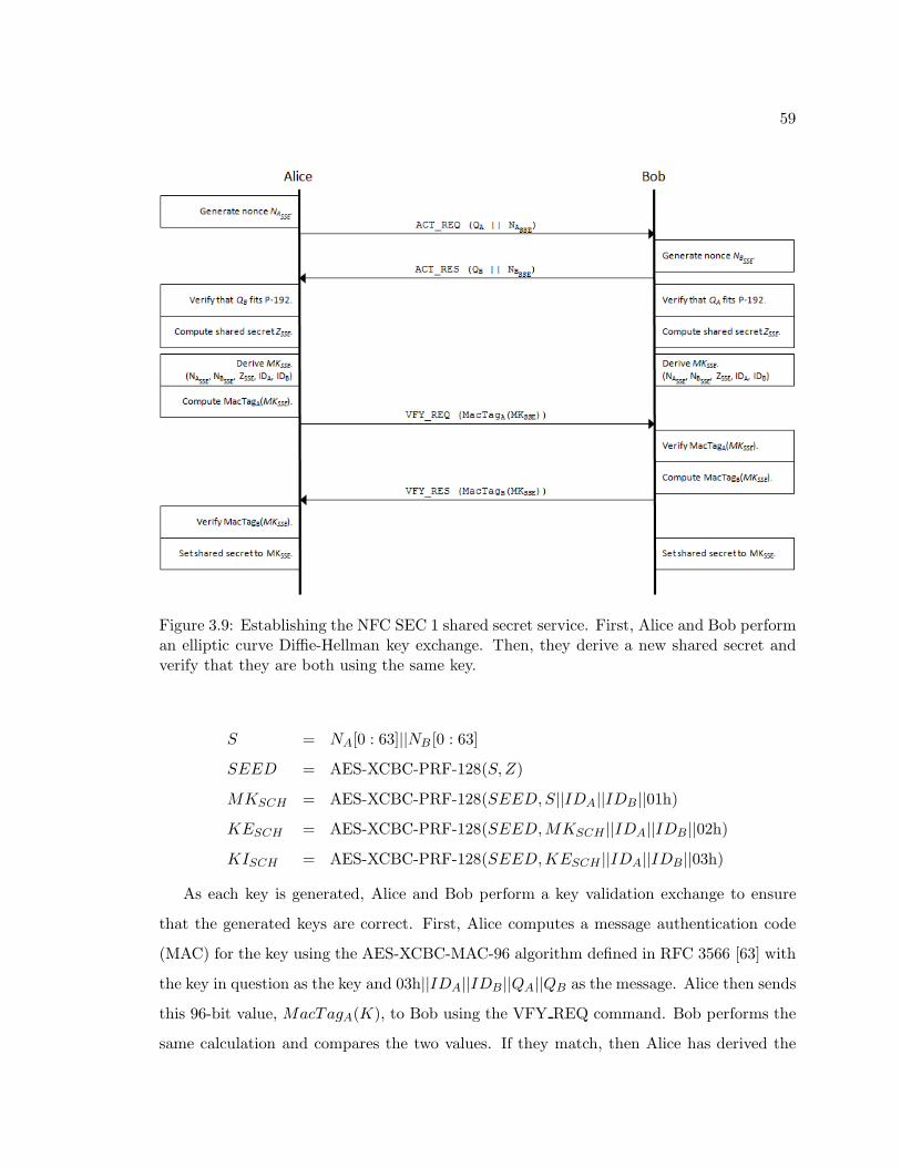
59
Figure 3.9: Establishing the NFC SEC 1 shared secret service. First, Alice and Bob performan elliptic curve Diffie-Hellman key exchange. Then, they derive a new shared secret andverify that they are both using the same key.
S = NA[0 : 63]||NB [0 : 63]
SEED = AES-XCBC-PRF-128(S,Z)
MKSCH = AES-XCBC-PRF-128(SEED,S||IDA||IDB ||01h)
KESCH = AES-XCBC-PRF-128(SEED,MKSCH ||IDA||IDB ||02h)
KISCH = AES-XCBC-PRF-128(SEED,KESCH ||IDA||IDB ||03h)
As each key is generated, Alice and Bob perform a key validation exchange to ensure
that the generated keys are correct. First, Alice computes a message authentication code
(MAC) for the key using the AES-XCBC-MAC-96 algorithm defined in RFC 3566 [63] with
the key in question as the key and 03h||IDA||IDB ||QA||QB as the message. Alice then sends
this 96-bit value, MacTagA(K), to Bob using the VFY REQ command. Bob performs the
same calculation and compares the two values. If they match, then Alice has derived the
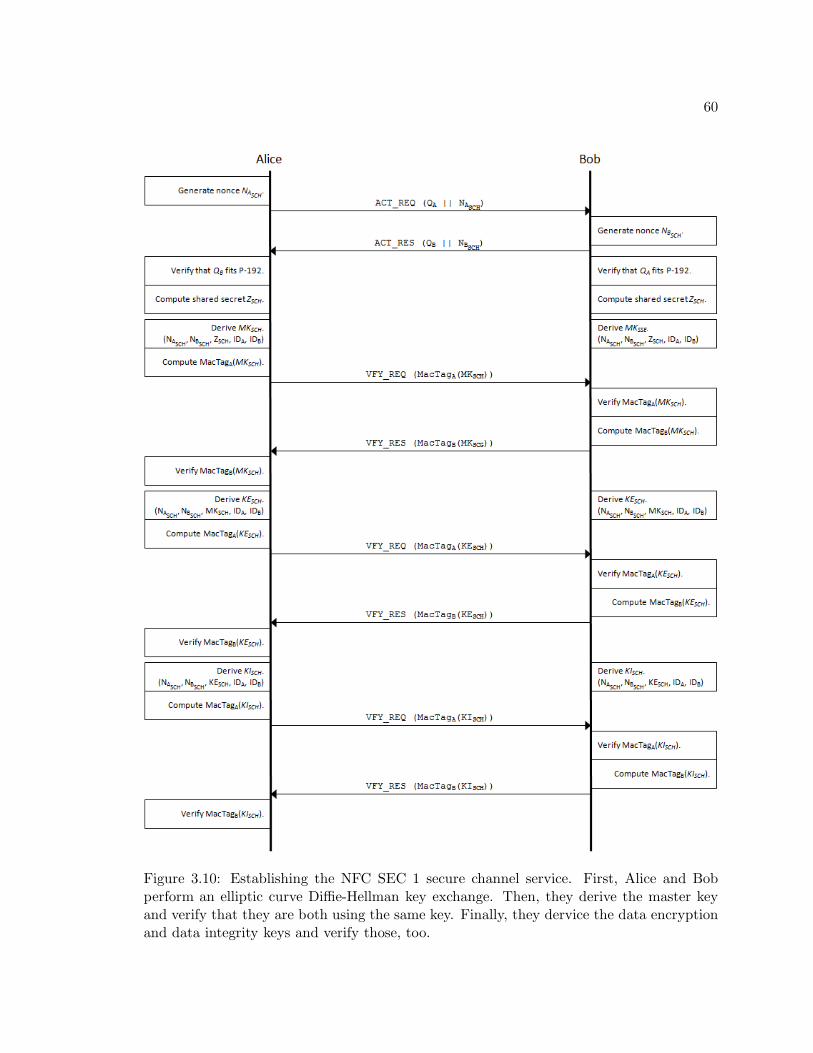
60
Figure 3.10: Establishing the NFC SEC 1 secure channel service. First, Alice and Bobperform an elliptic curve Diffie-Hellman key exchange. Then, they derive the master keyand verify that they are both using the same key. Finally, they dervice the data encryptionand data integrity keys and verify those, too.
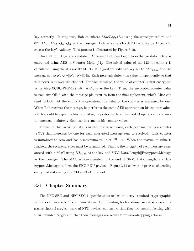
61
key correctly. In response, Bob calculates MacTagB(K) using the same procedure and
02h||IDB ||IDA||QB ||QA as the message. Bob sends a VFY RES response to Alice, who
checks the key’s validity. This process is illustrated by Figure 3.10.
Once all four keys are validated, Alice and Bob can begin to exchange data. Data is
encrypted using AES in Counter Mode [64]. The initial value of the 128 bit counter is
calculated using the AES-XCBC-PRF-128 algorithm with the key set to MKSCH and the
message set to KISCH ||NA||NB ||04h. Each peer calculates this value independently so that
it is never sent over the channel. For each message, the value of counter is first encrypted
using AES-XCBC-PRF-128 with KESCH as the key. Then, the encrypted counter value
is exclusive-OR’d with the message plaintext to form the final ciphertext, which Alice can
send to Bob. At the end of the operation, the value of the counter is increased by one.
When Bob receives the message, he performs the same AES operation on his counter value,
which should be equal to Alice’s, and again performs the exclusive-OR operation to recover
the message plaintext. Bob also increments his counter value.
To ensure that arriving data is in the proper sequence, each peer maintains a counter
(SNV) that increases by one for each encrypted message sent or received. This counter
is initialized to zero and has a maximum value of 224 − 1. When the maximum value is
reached, the secure services must be terminated. Finally, the integrity of each message guar-
anteed with a MAC using KISCH as the key and SNV||Data Length||Encrypted Message
as the message. The MAC is concatenated to the end of SNV, Data Length, and En-
crypted Message to form the ENC PDU payload. Figure 3.11 shows the process of sending
encrypted data using the NFC-SEC-1 protocol.
3.6 Chapter Summary
The NFC-SEC and NFC-SEC-1 specifications utilize industry standard cryptographic
protocols to secure NFC communications. By providing both a shared secret service and a
secure channel service, users of NFC devices can ensure that they are communicating with
their intended target and that their messages are secure from eavesdropping attacks.
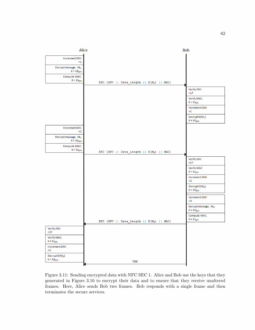
62
Figure 3.11: Sending encrypted data with NFC SEC 1. Alice and Bob use the keys that theygenerated in Figure 3.10 to encrypt their data and to ensure that they receive unalteredframes. Here, Alice sends Bob two frames. Bob responds with a single frame and thenterminates the secure services.
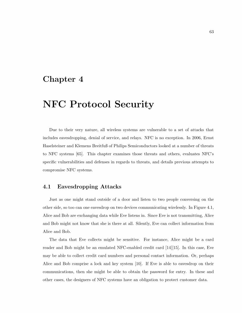
63
Chapter 4
NFC Protocol Security
Due to their very nature, all wireless systems are vulnerable to a set of attacks that
includes eavesdropping, denial of service, and relays. NFC is no exception. In 2006, Ernst
Haselsteiner and Klemens Breitfuß of Philips Semiconductors looked at a number of threats
to NFC systems [65]. This chapter examines those threats and others, evaluates NFC’s
specific vulnerabilities and defenses in regards to threats, and details previous attempts to
compromise NFC systems.
4.1 Eavesdropping Attacks
Just as one might stand outside of a door and listen to two people conversing on the
other side, so too can one eavesdrop on two devices communicating wirelessly. In Figure 4.1,
Alice and Bob are exchanging data while Eve listens in. Since Eve is not transmitting, Alice
and Bob might not know that she is there at all. Silently, Eve can collect information from
Alice and Bob.
The data that Eve collects might be sensitive. For instance, Alice might be a card
reader and Bob might be an emulated NFC-enabled credit card [14][15]. In this case, Eve
may be able to collect credit card numbers and personal contact information. Or, perhaps
Alice and Bob comprise a lock and key system [10]. If Eve is able to eavesdrop on their
communications, then she might be able to obtain the password for entry. In these and
other cases, the designers of NFC systems have an obligation to protect customer data.
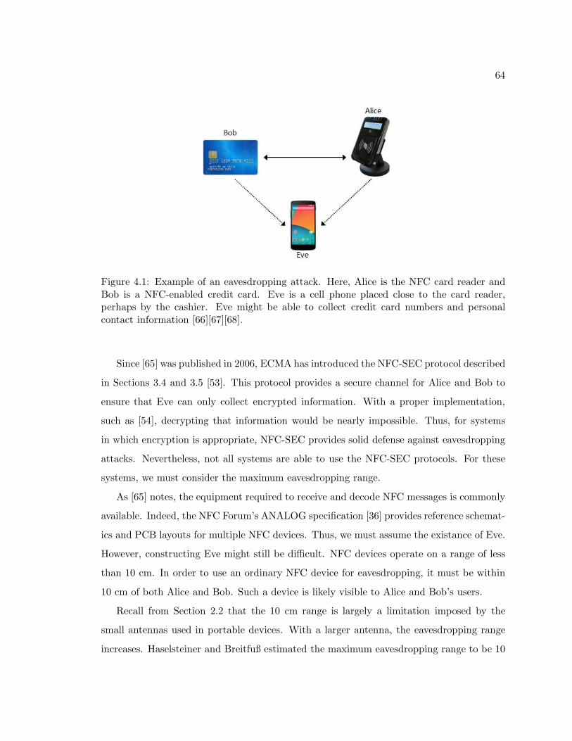
64
Figure 4.1: Example of an eavesdropping attack. Here, Alice is the NFC card reader andBob is a NFC-enabled credit card. Eve is a cell phone placed close to the card reader,perhaps by the cashier. Eve might be able to collect credit card numbers and personalcontact information [66][67][68].
Since [65] was published in 2006, ECMA has introduced the NFC-SEC protocol described
in Sections 3.4 and 3.5 [53]. This protocol provides a secure channel for Alice and Bob to
ensure that Eve can only collect encrypted information. With a proper implementation,
such as [54], decrypting that information would be nearly impossible. Thus, for systems
in which encryption is appropriate, NFC-SEC provides solid defense against eavesdropping
attacks. Nevertheless, not all systems are able to use the NFC-SEC protocols. For these
systems, we must consider the maximum eavesdropping range.
As [65] notes, the equipment required to receive and decode NFC messages is commonly
available. Indeed, the NFC Forum’s ANALOG specification [36] provides reference schemat-
ics and PCB layouts for multiple NFC devices. Thus, we must assume the existance of Eve.
However, constructing Eve might still be difficult. NFC devices operate on a range of less
than 10 cm. In order to use an ordinary NFC device for eavesdropping, it must be within
10 cm of both Alice and Bob. Such a device is likely visible to Alice and Bob’s users.
Recall from Section 2.2 that the 10 cm range is largely a limitation imposed by the
small antennas used in portable devices. With a larger antenna, the eavesdropping range
increases. Haselsteiner and Breitfuß estimated the maximum eavesdropping range to be 10
65
meters for NFC devices communicating in active mode and 1 meter for devices using the
passive mode [65].
In [69], Brown et al. construct an experiment in which they emulate a transmitting
NFC device with a one turn circular coil antenna with a radius of 1.5 cm. This device
transmitted a square wave at 108 kHz in order to approximate an active fc/128 device using
100% ASK. Using a second antenna similar to the first, the authors were able to receive and
decode the square wave signal at a distance of 0.5 meters when the transmit field strength
was set to 0.5 A/m. At a strength of 1.5 A/m, the authors were able to receive a signal at
a distance of 0.7 meters and at 4.5 A/m, a distance of 0.9 meters.
The NFCIP-1 specification requires a minimum RF field strength of 1.5 A/m and al-
lows a maximum strength of 7.5 A/m [33]. Thus, the experiments in [69] show that the
eavesdropping range for active NFC devices at fc/128 is longer than 10 cm. Indeed, at the
required minimum RF strength of 1.5 A/m, the eavesdropping range is approximately 7x
the normal operating range. At higher strengths, the range is even longer.
In addition to the above experiments, Brown et al. constructed a second setup in which
they used a shopping cart as the eavesdropping antenna. In this scenario, they were able to
receive the emulated NFC signal at a range of 0.3 meters when the transmit field strength
was 1.5 A/m and 0.4 meters at a strength of 4.5 A/m. This distance is not the 10 meters
predicted by [65], but it might be far enough for a clever customer to use his shopping cart
as an eavesdropping antenna to record payment transactions. Further, it shows that an
eavesdropping antenna need not always be precisely designed.
As noted in [65] and [70], the eavesdropping range of passive NFC communications
should be smaller than it is for active communications. In [71], the authors conduct an
experiment in which they use an off-the-shelf NFC-enabled cellular phone and a typical
NFC card reader to conduct transactions in passive mode. In addition, they construct
two eavesdropping antennas by attaching an oscilloscope to both a MiFare UltraLight label
and a MiFar Classic card. After performing the experiments with the antennas placed
in numerous positions, the author concludes that the maximum eavesdropping range for
passive NFC communications is approximately 0.3 meters.
The experiments in [69] and [71] demonstrate that NFC’s maximum operating range of
66
10 cm is not a sufficient defense against eavesdropping attacks. While neither experiment
achieved the predicted eavesdropping range of 10 meters, better antenna design increases
the maximum eavesdropping range significantly. In [72], Hancke was able to eavesdrop at
ranges of up to 15 meters with large, commercially-avaiable antennas. While such setups
might not be practical for eavesdropping on credit card transactions, they could instead be
used to skim the same data from passersby with NFC-enabled cards in their wallets.
4.2 Data Alteration Attacks
A second classification of attacks are those that modify the data that a NFC device
receives. Haselsteiner and Breitfuß consider three variations of data alteration in [65]: data
corruption, data modification, and data insertion. The simplest of these is data corruption.
In this attack, a rogue device transmits data on the 13.56 MHz frequency at such a strength
that any other data transmitted on that frequency would be corrupt. Alternatively, a device
could continuously generate a strong 13.56 MHz signal, preventing NFC devices from turning
on their own RF fields. As noted in Section 2.3.2, a NFC device executes the “Initial RF
Collision Avoidance” protocol before enabling its RF field. If it detects another field with
a strength of at least 0.1875 A/m (rms), then it does not turn on its own field [33]. The
result of both attacks is a denial of service.
NFC offers no protection against a denial-of-service attack. However, NFC devices are
able to detect other RF fields, so such attacks should always be detectable [65]. Nevertheless,
these simple attacks could prevent proximity cards from functioning properly, prevent the
NFC payment transactions from completing, and prevent the transmission of important
medical data.
Data modification attacks are more complex and their feasability depends on both the
data rate and transmission mode that the victim devices employ. Active devices operating
at fc/128 employ a modified Miller encoding with 100ASK modulation (see Figure 2.4). In
this scenario, the RF field is either at full strength or it is off. When the field is off, a
rogue device could fill the pause with a signal at full strength. However, when the field
is at full strength, the attacker has no practical way to cancel out that signal. Thus,

67
Figure 4.2: Data modification attack at 100% ASK, as employed by an active NFC deviceoperating at fc/128. In scenarios a and b, the rogue device detects a ‘0’ bit and doesnothing. At best, the attacker could cause data corruption by causing the receiver to detecttwo consecutive bit periods with no pauses, but this is equivalent to the data collision attackdiscussed previously. In scenario c, the rogue device detects a ‘1’ and turns on its RF fieldfor the next bit period. However, the next bit was already a ‘0’, so the data arrives at thereceiver unchanged. In scenario d, the rogue detects a ‘1’, turns on its RF field, and changesthe next ‘1’ bit into a ‘0’ bit. The receiver sees a valid bit sequence and does not know thatthe data has been changed.
data modification in the active, fc/128 mode is only possible for two consecutive ‘1’ bits.
Figure 4.2 demonstrates this.
In all other communication modes, NFC devices use a 10% ASK modulation scheme
in which the signal levels are 100% and 82%. Here, a rogue device could add a signal to
the transmitted 82% signals such that that the receiver sees the 82% signals as 100% and
the 100% signals as 82%. Since the NFC specification allows a large range for the RF field
strength (1.5-7.5 A/m [33]), such an attack seems plausible. However, the rogue device
would need to predict when the transmitter sent an 82% signal quickly enough to change
its value.
These data modification attacks are easily defeated. NFC-SEC offers data integrity
mechanisms, so devices utilizing this protocol could detect any data modifications. For
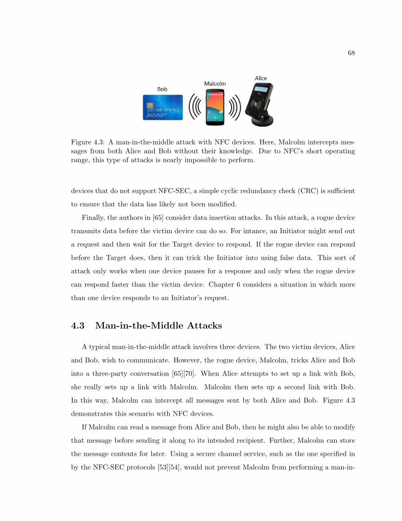
68
Figure 4.3: A man-in-the-middle attack with NFC devices. Here, Malcolm intercepts mes-sages from both Alice and Bob without their knowledge. Due to NFC’s short operatingrange, this type of attacks is nearly impossible to perform.
devices that do not support NFC-SEC, a simple cyclic redundancy check (CRC) is sufficient
to ensure that the data has likely not been modified.
Finally, the authors in [65] consider data insertion attacks. In this attack, a rogue device
transmits data before the victim device can do so. For intance, an Initiator might send out
a request and then wait for the Target device to respond. If the rogue device can respond
before the Target does, then it can trick the Initiator into using false data. This sort of
attack only works when one device pauses for a response and only when the rogue device
can respond faster than the victim device. Chapter 6 considers a situation in which more
than one device responds to an Initiator’s request.
4.3 Man-in-the-Middle Attacks
A typical man-in-the-middle attack involves three devices. The two victim devices, Alice
and Bob, wish to communicate. However, the rogue device, Malcolm, tricks Alice and Bob
into a three-party conversation [65][70]. When Alice attempts to set up a link with Bob,
she really sets up a link with Malcolm. Malcolm then sets up a second link with Bob.
In this way, Malcolm can intercept all messages sent by both Alice and Bob. Figure 4.3
demonstrates this scenario with NFC devices.
If Malcolm can read a message from Alice and Bob, then he might also be able to modify
that message before sending it along to its intended recipient. Further, Malcolm can store
the message contents for later. Using a secure channel service, such as the one specified in
by the NFC-SEC protocols [53][54], would not prevent Malcolm from performing a man-in-
69
the-middle attack. Rather, Malcolm would simply establish two secure channels, one each
with Alice and Bob. One counter to this problem lies with authentication services, in which
public keys are verified by a third-party. NFC-SEC does not require such authentication.
Nevertheless, NFC does offer strong defenses against man-in-the-middle attacks. Con-
sider the situation in Figure 4.3. Here, Alice is an active device, Bob is a passive device,
and Malcolm can use both modes. To begin the transaction, Alice sends a message to Bob,
which Malcolm intercepts. At the same time, Malcolm must also ensure that Bob does not
receive Alice’s message. If Malcolm disturbs the transmission such that Bob cannot read
it, then Alice would be able to detect Malcolm’s transmissions and she could then stop the
transaction. However, let us assume that Alice does not check for this distruption since
NFCIP-1 [33] does not require it. Once Malcolm has the message from Alice, he must relay
that message to Bob. In doin so, Malcolm must enable his RF field. Since Bob is a passive
device, Alice will have left her RF field on so that Bob use it to respond. With two active
RF fields, Bob will not likely be able to understand the message that Malcolm relays.
What about two active devices? As with the previous scenario, Malcolm must first
disturb Alice’s transmission so that Bob cannot receive it. Again, Alice could check for this
disturbance and stop the transaction. As before, let us assume that she does not perform
this check. This time, Alice turns off her RF field so that Bob can use his own field to
respond. Next, Malcolm must relay Alice’s message to Bob. When he does so, both Bob
and Alice will receive that message. Alice can again detect a problem since Malcolm’s
message was not what she expected from Bob.
In either case, a man-in-the-middle attack with three NFC devices is simply not feasbile.
In order for it to work, Alice and Bob would need to be far enough apart so that they could
not detect each other and Malcolm would have to move such that he is only ever within
range of either Alice or Bob. Since NFC devices operate with a range of only 4-10 cm, a
device capable of performing such feats would almost certainly be detectable by the parties
in control of Alice and Bob.
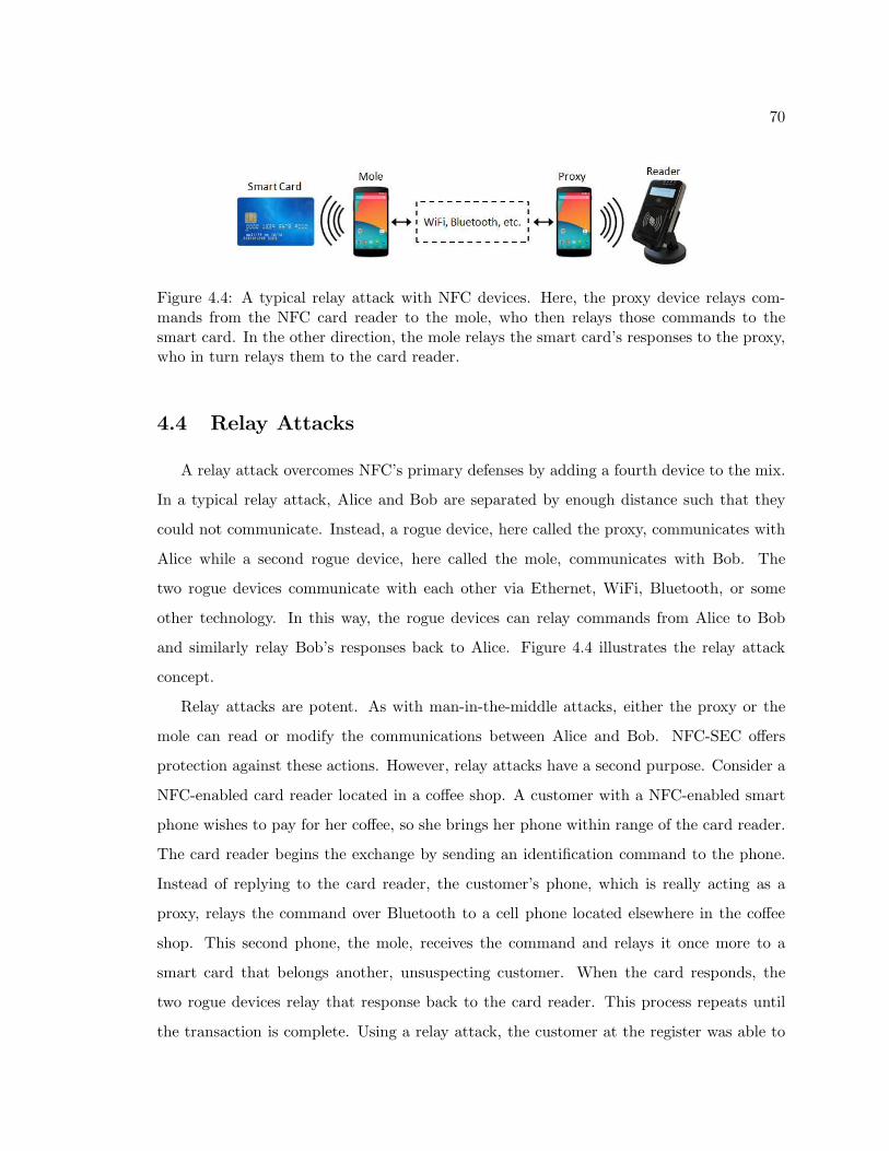
70
Figure 4.4: A typical relay attack with NFC devices. Here, the proxy device relays com-mands from the NFC card reader to the mole, who then relays those commands to thesmart card. In the other direction, the mole relays the smart card’s responses to the proxy,who in turn relays them to the card reader.
4.4 Relay Attacks
A relay attack overcomes NFC’s primary defenses by adding a fourth device to the mix.
In a typical relay attack, Alice and Bob are separated by enough distance such that they
could not communicate. Instead, a rogue device, here called the proxy, communicates with
Alice while a second rogue device, here called the mole, communicates with Bob. The
two rogue devices communicate with each other via Ethernet, WiFi, Bluetooth, or some
other technology. In this way, the rogue devices can relay commands from Alice to Bob
and similarly relay Bob’s responses back to Alice. Figure 4.4 illustrates the relay attack
concept.
Relay attacks are potent. As with man-in-the-middle attacks, either the proxy or the
mole can read or modify the communications between Alice and Bob. NFC-SEC offers
protection against these actions. However, relay attacks have a second purpose. Consider a
NFC-enabled card reader located in a coffee shop. A customer with a NFC-enabled smart
phone wishes to pay for her coffee, so she brings her phone within range of the card reader.
The card reader begins the exchange by sending an identification command to the phone.
Instead of replying to the card reader, the customer’s phone, which is really acting as a
proxy, relays the command over Bluetooth to a cell phone located elsewhere in the coffee
shop. This second phone, the mole, receives the command and relays it once more to a
smart card that belongs another, unsuspecting customer. When the card responds, the
two rogue devices relay that response back to the card reader. This process repeats until
the transaction is complete. Using a relay attack, the customer at the register was able to
71
purchase her coffee with another customer’s card. Note that since the two rogue devices
simply relayed messages, NFC-SEC and other security protocols would not have prevented
the relay attack.
There have been numerous relay attacks on NFC devices. In [73], Francis, et al. devise
a relay attack using four NFC-enabled mobile phones. Alice and the proxy were Nokia
6212 Classic phones [74], while Bob and the mole were Nokia 6131 phones [75]. Each of
these phones runs the Nokia Series 40 operating system and supports Java applications. In
order to demonstrate the relay attack, the authors established a Bluetooth link between the
proxy and the mole and wrote custom Java applications to send messages in both directions
through the relay train. While this attack was not connected to any real-world systems, it
nevertheless showed that NFC devices, like other wireless systems, are vulnerable to relay
attacks.
The phones used in the attack presented in [73] were some of the first phones to support
NFC and both are now discontinued. However, modern systems are still susceptible to
relay attacks. Authors Wang, et al. describe a relay attack in [76] that uses HTC One
X [77] smart phones running Google’s Android 4 operating sytem and the Android Beam
application. Android Beam uses NFC to establish a Bluetooth link between two devices.
Many applications shipped on modern Android smart phones used Beam to communicate,
including YouTube and Chrome [76]. In this attack, Beam is used to establish Bluetooth
links between Alice and the proxy and between the mole and Bob while the link between
the two rogue devices runs over WiFi. As in the previous attack with Nokia phones, the
authors are able to relay messages from Alice to Bob via the proxy and mole pair.
Another application on modern Android smart phones that uses NFC is Google Wallet.
The Google Wallet application interfaces with JavaCard applets on the phone’s secure ele-
ment that store credit card and other payment information. With Google Wallet, customers
can use their phones to pay for purchases at NFC-enabled terminals. In [78], Roland, et al.
demonstrate a relay attack that works with Google Wallet. Using a commercial, off-the-shelf
point of sale terminal and a MasterCard PayPass credit card supporting EMV Mag-Stripe
security, the authors were able to demonstrate a successful relay attack. Google patched
the Wallet application in September 2012 to prevent this specific attack, but it might yet
72
be vulnerable to other forms of attack.
Often, the major limiting factor for any of the above relay attacks is distance. In order
to communicate with the victim’s smart card or NFC device, the mole must be within
operating range, which is typically less than 10 cm [28]. Therefore, the attacker operating
the mole device might have to be uncomfortably close to his victim. Indeed, contactless
smart cards rely on this short operating range to ensure that the card’s owner is in fact
present at the point of sale. But what if the range was not so limited?
In [79], Kfir and Wool devise NFC devices that are capable of transmitting and receiving
NFC messages at much longer distances than 10 cm. To do so, they wrapped loops of wire
around an otherwise unmodified NFC device. Then, they connected the wire to a set of
power amplifiers and filters. Finally, they added an optimally-sized antenna made from
copper tubing. This device acted as a proxy and was capable of interacting with the card
reader at distances of up to 50 meters. For an NFC transaction in which both Alice and
Bob would be active devices, two of these proxy devices are sufficient to carry out a long-
distance relay attack.
However, in the case of a smart card transaction, the mole communicates with a passive
device. To do this, the mole must first power the smart card, which is only possible when
the card is within the mole’s reactive near field (see Figure 2.1), which limits the maximum
distance between the mole and the smart card to only 3.52 meters. In fact, due to con-
straints on antenna size and power, Kfir and Wool were only able to increase the reliable
communication range to 40 cm with a mole device similar to their proxy device [79]. With
access to the NFC device driver software and expensive signal processing components, they
were able to increase this range further to 55 cm.
The relay attack in [79] was still limited by the distance between the proxy and the
mole. After all, the connectivity options commonly found on NFC-enabled devices, such
as Bluetooth and WiFi, are themselves designed only to work at distances of less than 100
meters [29][30]. In “Long Distance Relay Attack” [80], authors attempt to remove this
limitation by introducing more devices to the attack architecture. Figure 4.5 illustrates this
new approach. With the expanded relay attack architecture, Sportiello and Ciardulli were
able to demonstrate a relay attack over a distance of ∼541 km with an ePassport in Italy
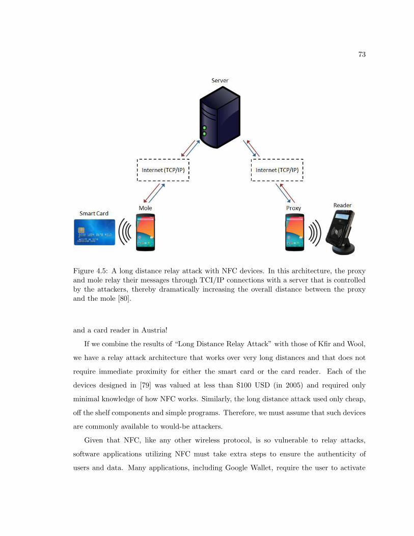
73
Figure 4.5: A long distance relay attack with NFC devices. In this architecture, the proxyand mole relay their messages through TCI/IP connections with a server that is controlledby the attackers, thereby dramatically increasing the overall distance between the proxyand the mole [80].
and a card reader in Austria!
If we combine the results of “Long Distance Relay Attack” with those of Kfir and Wool,
we have a relay attack architecture that works over very long distances and that does not
require immediate proximity for either the smart card or the card reader. Each of the
devices designed in [79] was valued at less than $100 USD (in 2005) and required only
minimal knowledge of how NFC works. Similarly, the long distance attack used only cheap,
off the shelf components and simple programs. Therefore, we must assume that such devices
are commonly available to would-be attackers.
Given that NFC, like any other wireless protocol, is so vulnerable to relay attacks,
software applications utilizing NFC must take extra steps to ensure the authenticity of
users and data. Many applications, including Google Wallet, require the user to activate
74
enable the NFC antenna with a PIN. While PINs do increase security, they also increase
the amount of time needed to complete a transaction. As speed and convenience are two of
NFC’s primary selling points, a PIN system might not be appropriate for all applications
[80][78].
Another simple solution to the relay attack problem is the faraday cage [78]. If a smart
card is enclosed in metal, such as aluminum foil, then a mole will have extreme difficulty
communicating with it. Faraday cages are already in use for some systems. Indeed, many
proximity cards (e.g. security badges, green cards) come with metal envelopes. Unfortu-
nately, this solution is not practical in all cases. Whether for style, simplicity, cost, or other
reasons, most of us do not carry metallic purses and wallets. Thus, most smart cards and
other NFC/RFID devices (e.g. ePassports) remain vulnerable.
The attacks against EMV, Google Wallet, and ePassports worked because these spec-
ifications allow for long response delays. In some cases, these long delays are necessary.
For instance, a passive device might need to perform a cryptographic operation in response
to a command from an active card reader [80]. For this reason, ISO 14443 [40] allows the
responding device to ask for as much as ∼4.95 seconds to respond to a command. With
current technology, five seconds is a very long time. Certainly, it is enough time to re-
lay messages across the world via the Internet. Therefore, applications should implement
tighter time controls for transactions that are not likely to need so much time for processing.
To combat the long distance relay attack, one might imagine using GPS location data to
ensure that the two NFC devices are located within the expected 10 cm range. Indeed, [76]
and [73] do suggest doing just that. However, GPS technology is not reliable at distances
of less than a few meters [81] and it is even less reliable indoors since microwaves are
attenuated and scattered by many common building materials. Thus, relay attacks within
a shop might still be viable.
A second approach to combating the long distance relay attack involves sensors. Modern
smart phones contain many sensors that the payment application could query. In [82], Halevi
et al. use ambient sound and light data to determine whether the card reader and smart
card are in the same location. With audio, the authors reported a 100% success rate for
detecting when the two devices are in different locations. With light, they report about a
75
90% success rate. In both cases, sensor data makes the job of a would-be relay attacker
significantly more difficult.
However, the authors in [82] used two phones of the same model to record their audio and
light data. Replacing one phone with a card reader, which likely has different sensors and
processing chips, might significantly weaken their results. Further, these sensing techniques
might have little promise if the attacker is in the same general location as the card reader.
Another attempt at using sensor data attempts to improve upon these results by using
temperature sensors [83], Urien and Piramuthu devise an experiment in which both the card
reader and the smart card are equipped with temperature sensors. In theory, both sensors
should measure the same temperature when the card is placed in close proximity to the
reader. When the reader detects a card, it begins a key exchange based on Elliptic-Curve
Diffie Hellman (see Sections 3.2). A combination of secret keys, random nonces, and the
temperature data allow the two devices to establish a shared secret. If the temperatures are
not within the set tolerance, then the transaction is aborted. Otherwise, the two devices
begin a time-limited exchange of bits. In order to prevent replay attacks, this bit exchange
includes some information that should be secret. With a combination of temperature data
and the time-limited exchange, the authors conclude that their approach makes relay attacks
on NFC devices nearly impossible.
4.5 Chapter Summary
Near Field Communication, like any other wireless protocol, is vulnerable to a number
of attacks. These attacks can allow malicious actors to obtain sensitive information, falsify
credentials, and deny service to legitimate users. The short operating range of NFC de-
vices provides good defense against some of these attacks, especially the man-in-the-middle
attack. The NFC-SEC protocols provide solid defense against eavesdropping and data al-
teration attacks for systems in which secure channels are appropriate, though systems that
cannot implement NFC-SEC are still vulnerable. Finally, a combination of sensor data and
time-limited challenges provides great defense against relay attacks. Generally, NFC, when
combined with application-level security, is fairly robust against common attacks.
76
Chapter 5
NFC Testing Platform
In order to test the security of modern NFC devices, I created the NFC teting platform
described in this Chapter. The NFC testing platform consists of modern, open-source
hardware (Section 5.1) and free, open-source software (Section 5.2). This combination
makes it the ideal platform for academic experimentation.
5.1 Hardware
The hardware for the NFC testing platform consists of a small computing board, three
NFC-enabled devices, and a number of supporting elements. The hardware was selected
with three criteria in mind: availability, affordability, and similarity to real-world NFC
devices. Figure 5.2 is a photograph of the NFC testing platform’s primary hardware com-
ponents, which are:
• PandaBoard ES : The large board in the top-right corner of Figure 5.2 is a PandaBoard
ES [84]. This fairly inexpensive (less than US$200 at the time of this writing) platform
contains hardware similar to that found in mobile phones and other NFC-enabled
devices. At the heart of the PandaBoard ES is a Texas Instruments OMAP4460
system on chip (SoC), which contains a dual-core ARM Cortex-A9 microprocessors,
an OpenGL ES v2.0 compatible graphics core, and 2 GB of system memory. Other
features include 802.11b/g/n WiFi, Bluetooth v2.1 EDR, HDMI outputs, two USB
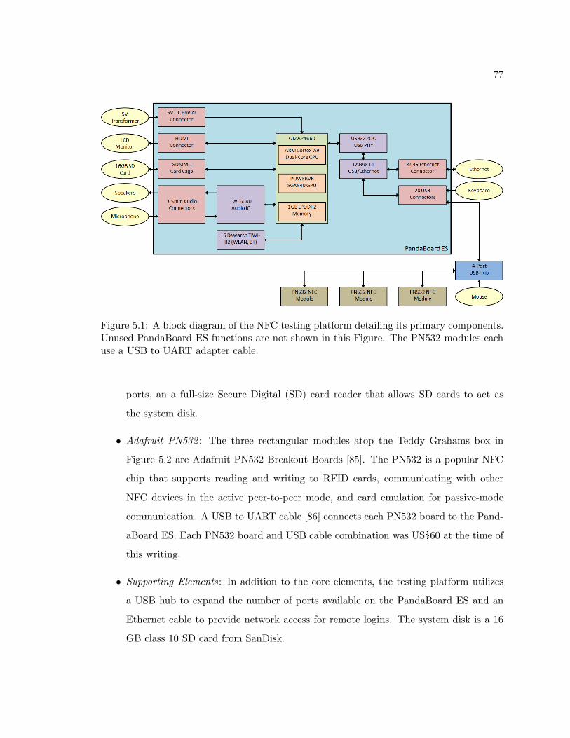
77
Figure 5.1: A block diagram of the NFC testing platform detailing its primary components.Unused PandaBoard ES functions are not shown in this Figure. The PN532 modules eachuse a USB to UART adapter cable.
ports, an a full-size Secure Digital (SD) card reader that allows SD cards to act as
the system disk.
• Adafruit PN532 : The three rectangular modules atop the Teddy Grahams box in
Figure 5.2 are Adafruit PN532 Breakout Boards [85]. The PN532 is a popular NFC
chip that supports reading and writing to RFID cards, communicating with other
NFC devices in the active peer-to-peer mode, and card emulation for passive-mode
communication. A USB to UART cable [86] connects each PN532 board to the Pand-
aBoard ES. Each PN532 board and USB cable combination was US$60 at the time of
this writing.
• Supporting Elements: In addition to the core elements, the testing platform utilizes
a USB hub to expand the number of ports available on the PandaBoard ES and an
Ethernet cable to provide network access for remote logins. The system disk is a 16
GB class 10 SD card from SanDisk.
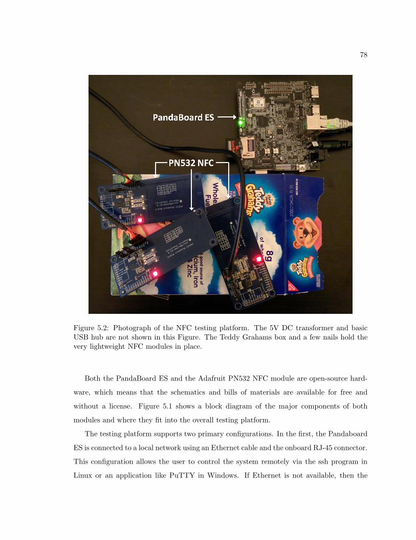
78
Figure 5.2: Photograph of the NFC testing platform. The 5V DC transformer and basicUSB hub are not shown in this Figure. The Teddy Grahams box and a few nails hold thevery lightweight NFC modules in place.
Both the PandaBoard ES and the Adafruit PN532 NFC module are open-source hard-
ware, which means that the schematics and bills of materials are available for free and
without a license. Figure 5.1 shows a block diagram of the major components of both
modules and where they fit into the overall testing platform.
The testing platform supports two primary configurations. In the first, the Pandaboard
ES is connected to a local network using an Ethernet cable and the onboard RJ-45 connector.
This configuration allows the user to control the system remotely via the ssh program in
Linux or an application like PuTTY in Windows. If Ethernet is not available, then the
79
Pandaboard ES can connect to the local network via WiFi or Bluetooth by utilizing the LS
Research TiWi-R2 device. However, using this device seems to produce instability in the
system, often resulting in kernel panics and system freezes. Thus, the Ethernet connection
is preferable.
In the second configuration, the user can connect a keyboard, a mouse, and a monitor
directly to the Pandaboard ES, negating the need for network support. The monitor must
have an HDMI connector because the Pandaboard ES’s DVI connector is not fully functional
at the time of this writing. The keyboard and mouse should be connected via USB. Since
the Pandaboard ES has only two USB ports, a USB hub is necessary to utilize the keyboard,
mouse, and three NFC devices simultaneously. The prefered connection scheme uses a four-
port USB hub to connect the mouse and three NFC devices while the keyboard is connected
directly to the board, as shown in Figure 5.1.
Other hardware was considered for inclusion in the NFC testing platform. Compared to
the Pandaboard ES, the Raspberry Pi [87] has less memory at only 512MB, has a much less
capable processer, and lacks the Pandaboard’s WiFi and Bluetooth capabilities. In addition,
the Raspberry Pi is less open than the Pandaboard ES, lacking public PCB design files.
Finally, the CPU used on the Raspberry Pi is no longer supported by many popular Linux
distributions. Despite these limitations, the Raspberry Pi could nevertheless serve as a
decent heart for a NFC test platform. It carries a much lower price than the PandaBoard
ES, has smaller physical dimensions, and has a large community of users.
Instead of a using a combination of the PandaBoard ES and the PN532 NFC module,
one might use a modern smartphone. Models like the LG Nexus 5 contain more powerful
hardware than the PandaBoard ES and use newer NFC chips. However, such devices
tend to carry high costs and are much less open than the PandaBoard ES. Additionally,
while programming an application for the PandaBoard ES is essentially no different than
programming an application for a typical personal computer, programming on a smartphone
requires the programmer to learn a new system of tools and restrictions.
Future iterations of the NFC testing platform might include more modern NFC devices
that support the NFC-SEC protocols, such as the PN533 [88]. At the time of this writ-
ing, no open-source hardware devices carry such a chip. A module similar to the PN532
80
from Adafruit but instead carrying a PN533 chip would certainly improve the NFC testing
platform.
5.2 Software
The operating system for the NFC testing platform is Ubuntu 12.04 LTS (Precise Pan-
golin) [89], a free, open-source Linux distribution. Ubuntu 12.04 is recommended by Texas
Instruments for the PandaBoard ES and is available as a pre-configured image. In addi-
tion, Ubuntu 12.04 was the development platform for Texas Instruments engineers and thus
provides packages to install additional drivers and utilities for the PandaBoard ES. The
operating system is stored on the 16 GB SanDisk SD card.
While the NFC testing platform uses Ubuntu, the PandaBoard ES is supported by
numerous other operating systems, including Fedora and Gentoo Linux. There are also
Android builds available for the PandaBoard ES, which more closely mirror the software
found on most smartphones. None of these alternative operating systems are recommended
by Texas Instruments, but all of them support the hardware just as well.
On top of Ubuntu, a free, open-source library called libnfc [90] provides low-level drivers
and utilities for interacting with the PN532 device as well as with many other NFC devices.
The software described in Section 6.2 was built against version 1.7rc7 of libnfc as this was
the latest version available at the time of the experiments.
Future versions of the NFC testing platform might incorporate other free, open-source
utilities such as libfreefare [90], which provides functions for working with MIFARE tags,
and any of the numerous libraries available for reading and writing NDEF records. Newer,
more stable versions of Ubuntu or another operating system would also improve the NFC
testing platform.
5.3 Implementation
In order to recreate the test platform, the user must first install Ubuntu 12.04 to a SD
card. Insert the card, then connect a monitor, keyboard, and mouse. Power the Pandaboard
81
ES to boot the system. For a wired Ethernet connection, simply connect a standard Cat5
cable. The included Network Manager software can configure wireless networks.
Next, update the system. The following commands in will update any pre-installed soft-
ware, add the TI repository for Pandaboard, and perform a full system upgrade. Then, they
install the Pandaboard ES software and firmware from the Texas Instruments repository
and configure the system to use it.
sudo sed --in-place=.bak -e ’s/\^# \(deb.*\)/\1/’ /etc/apt/sources.list
sudo apt-get update
sudo apt-get install python-software-properties
sudo add-apt-repository ppa:tiomap-dev/release
sudo apt-get update
sudo apt-get dist-upgrade
sudo apt-get install ubuntu-omap4-extras
sudo apt-get install --reinstall pvr-omap4-dkms
alsaucm -c PandaES set _verb HiFi
sudo flash-kernel --update-bootloader
Reboot the system. These next commands install some libraries and programs that
libnfc depends on.
sudo apt-get install libusb-dev libpcsclite-dev
sudo apt-get install libusb-0.1-4 libpcsclite1 libccid pcscd
sudo apt-get install subversion
sudo apt-get install debhelper dh-autoreconf libtool
sudo apt-get install dpkg-dev
Finally, install libnfc according to the instructions found on the libnfc website [90]. Once
that is finished, run the following commands to remove any unneeded software and allow
you to use libnfc and the Pandaboard ES properly. Remember to replace “username” with
your actual username!
82
sudo apt-get autoremove
useradd -a -G dialout username
With at least one PN532 connection via USB cable, use the nfc-list command. If no
devices are found, then something went wrong. Otherwise, everything is OK!
Mostly, the system behaved as expected. However, the WiFi module was quite flaky
and often caused the system to lock up. Using a wired Ethernet connection produced a
much more stable system. Additionally, logging into the system remotely via SSH improved
stability over using the Ubuntu GUI locally. Even with the above changes, the system would
still rarely lock up. Advisors in the #pandaboard IRC channel on the Freenode network
attributed these freezes to the SD card. While the SD card is necessary to boot the system,
using an attached USB drive for everything else might improve overall system stability.
5.4 Chapter Summary
The NFC testing platform allows researchers to test NFC hardware and software imple-
mentations for protocol correctness, security flaws, efficiency, and features. It is comprised
entirely of commercially-available, off-the-shelf, open-source hardware and free, open-source
software. This chapter described the many components that make up the NFC testing plat-
form and explained why those components were chosen. Additionally, this chapter provided
implementation details and noted limitations of the system.
83
Chapter 6
An Analysis of Double Target
Trouble
Section 2.3.2.1 describes a single-device detection protocol to ensure that a NFC device
communicates with only one other NFC device. This chapter details an experiment that
shows what happens when this protocol fails.
6.1 The Problem
Standard NFC transactions are point-to-point and only involve two devices: the Initiator
and the Target. When an Initiator wishes to communicate with a Target device, it first
performs the single-device detection algorithms described in Section 2.3.2.1. There are a
few reasons for this behavior.
First, all NFC devices communicate on the same 13.56 MHz frequency band. Thus,
multiple simultaneous transmissions in close proximity will cause interference. If more than
one Target device responded to the Initiator’s commands, then the Initiator might not be
able to read any responses at all. By selecting only one Target, the Initiator ensures that
only one standards-compliant NFC device is transmitting at any given time. Secondly,
some NFC transactions contain sensitive information. For instance, NFC devices can store
payment information, medical information, or access credentials. If the Initiator is not
84
careful to select the correct Target, then malicious devices could spoof this information.
Finally, the Initiator might wish to obtain information from a specific device with a known
identifier. In this case, the Initiator simply needs to select the correct Target from all
possible Target devices in range. The single-device detection algorithms can do this.
What happens if the single-device detection algorithm does not function as expected?
6.2 Proposed Experiment
In order to conduct this experiment, three PN532 NFC devices are connected to the
PandaBoard ES, as shown in Figure 5.2. Note that the three loop antennas are all touching
and that one NFC device is sandwiched between the other two. In this configuration, the
Initiator device is in the center and is flanked by the two Target devices.
Figure 6.1 illustrates the general testing procedure for each iteration of the Double
Target Trouble experiment. Each of three NFC devices was assigned an alias. Alice is the
Initiator device; Bob and Eve are the Target devices. First, the program configures the two
Target devices so that they are idly and waiting for an Initiator to communicate. Then, it
initializes Alice to look for a Target device. When she finds one, she transmits the message,
“Hello! I’m Alice!”. If either Target receives that message, then it responds with, “Hello
to you, too!”. If Alice receives a response, then she sends the message, “Who are you?”. If
Bob receives this second message from Alice, then he responds with, “I’m Bob!”. Likewise,
if Eve receives the second message, then she responds with, “I’m Eve!”. Not shown in
Figure 6.1 is a 5 second delay between each iteration of the test to allow all three devices
time to disconnect from libnfc.
If the single-device detection algorithm is working correctly, then Alice should receive a
response to each of her messages from Bob or Eve, but not both. Likewise, only Bob or
Eve should detect that they have paired with Alice. If Alice fails to receive a message, or
if she receives a message from an unknown sender, then a data collision has occurred. If
Bob and Eve do not agree on who responded to Alice, then the target selection process has
failed.
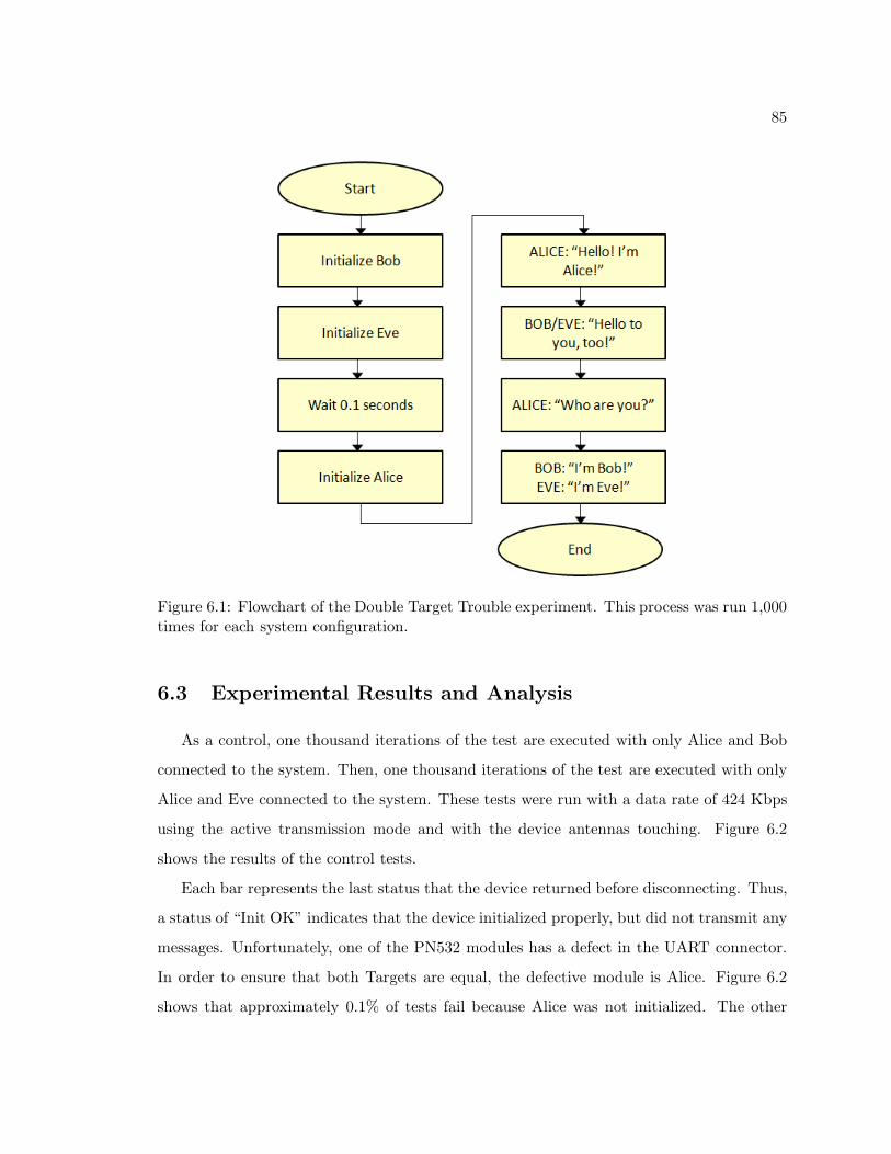
85
Figure 6.1: Flowchart of the Double Target Trouble experiment. This process was run 1,000times for each system configuration.
6.3 Experimental Results and Analysis
As a control, one thousand iterations of the test are executed with only Alice and Bob
connected to the system. Then, one thousand iterations of the test are executed with only
Alice and Eve connected to the system. These tests were run with a data rate of 424 Kbps
using the active transmission mode and with the device antennas touching. Figure 6.2
shows the results of the control tests.
Each bar represents the last status that the device returned before disconnecting. Thus,
a status of “Init OK” indicates that the device initialized properly, but did not transmit any
messages. Unfortunately, one of the PN532 modules has a defect in the UART connector.
In order to ensure that both Targets are equal, the defective module is Alice. Figure 6.2
shows that approximately 0.1% of tests fail because Alice was not initialized. The other
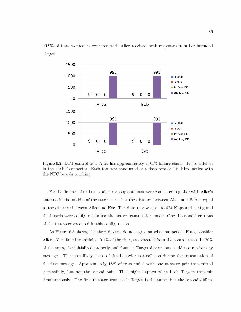
86
99.9% of tests worked as expected with Alice received both responses from her intended
Target.
Figure 6.2: DTT control test. Alice has approximately a 0.1% failure chance due to a defectin the UART connector. Each test was conducted at a data rate of 424 Kbps active withthe NFC boards touching.
For the first set of real tests, all three loop antennas were connected together with Alice’s
antenna in the middle of the stack such that the distance between Alice and Bob is equal
to the distance between Alice and Eve. The data rate was set to 424 Kbps and configured
the boards were configured to use the active transmission mode. One thousand iterations
of the test were executed in this configuration.
As Figure 6.3 shows, the three devices do not agree on what happened. First, consider
Alice. Alice failed to initialize 0.1% of the time, as expected from the control tests. In 20%
of the tests, she initialized properly and found a Target device, but could not receive any
messages. The most likely cause of this behavior is a collision during the transmission of
the first message. Approximately 18% of tests ended with one message pair transmitted
successfully, but not the second pair. This might happen when both Targets transmit
simultaneously. The first message from each Target is the same, but the second differs.
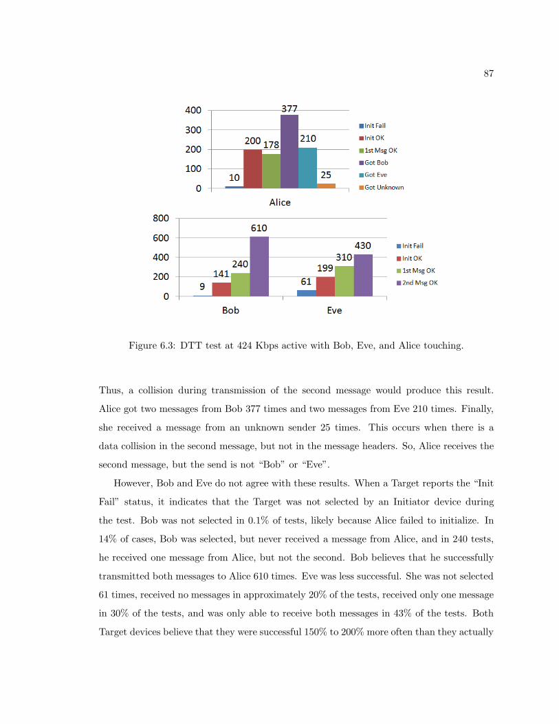
87
Figure 6.3: DTT test at 424 Kbps active with Bob, Eve, and Alice touching.
Thus, a collision during transmission of the second message would produce this result.
Alice got two messages from Bob 377 times and two messages from Eve 210 times. Finally,
she received a message from an unknown sender 25 times. This occurs when there is a
data collision in the second message, but not in the message headers. So, Alice receives the
second message, but the send is not “Bob” or “Eve”.
However, Bob and Eve do not agree with these results. When a Target reports the “Init
Fail” status, it indicates that the Target was not selected by an Initiator device during
the test. Bob was not selected in 0.1% of tests, likely because Alice failed to initialize. In
14% of cases, Bob was selected, but never received a message from Alice, and in 240 tests,
he received one message from Alice, but not the second. Bob believes that he successfully
transmitted both messages to Alice 610 times. Eve was less successful. She was not selected
61 times, received no messages in approximately 20% of the tests, received only one message
in 30% of the tests, and was only able to receive both messages in 43% of the tests. Both
Target devices believe that they were successful 150% to 200% more often than they actually
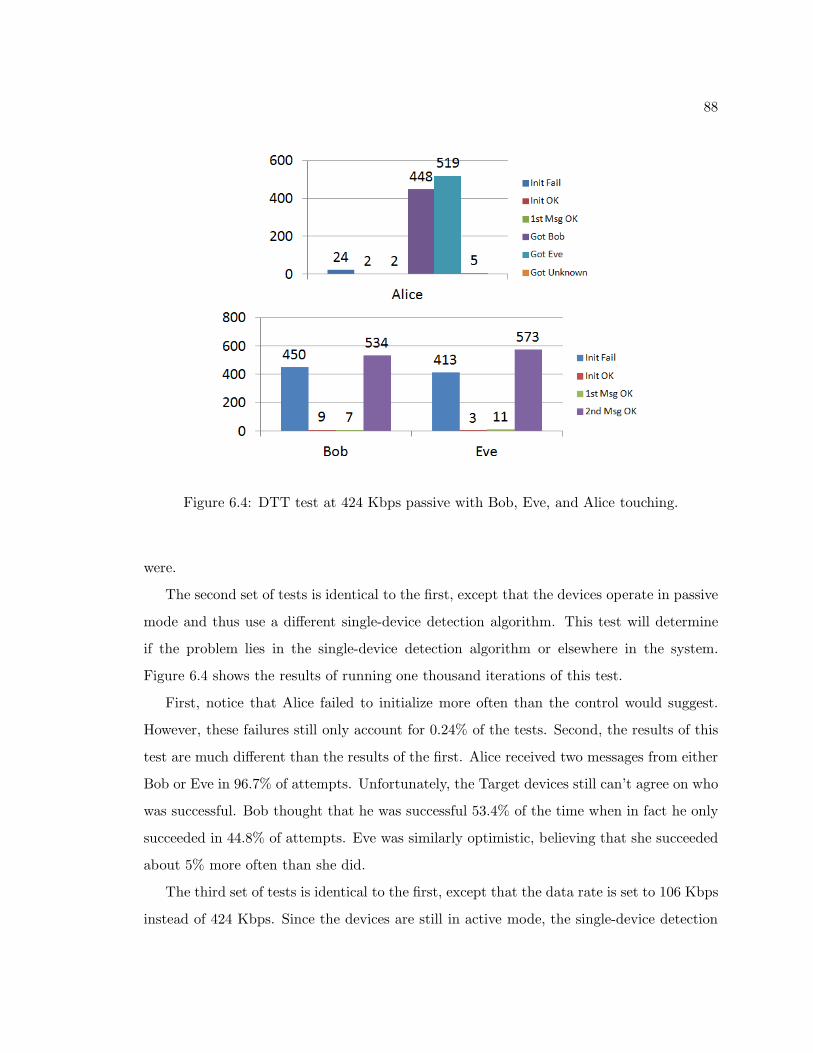
88
Figure 6.4: DTT test at 424 Kbps passive with Bob, Eve, and Alice touching.
were.
The second set of tests is identical to the first, except that the devices operate in passive
mode and thus use a different single-device detection algorithm. This test will determine
if the problem lies in the single-device detection algorithm or elsewhere in the system.
Figure 6.4 shows the results of running one thousand iterations of this test.
First, notice that Alice failed to initialize more often than the control would suggest.
However, these failures still only account for 0.24% of the tests. Second, the results of this
test are much different than the results of the first. Alice received two messages from either
Bob or Eve in 96.7% of attempts. Unfortunately, the Target devices still can’t agree on who
was successful. Bob thought that he was successful 53.4% of the time when in fact he only
succeeded in 44.8% of attempts. Eve was similarly optimistic, believing that she succeeded
about 5% more often than she did.
The third set of tests is identical to the first, except that the data rate is set to 106 Kbps
instead of 424 Kbps. Since the devices are still in active mode, the single-device detection
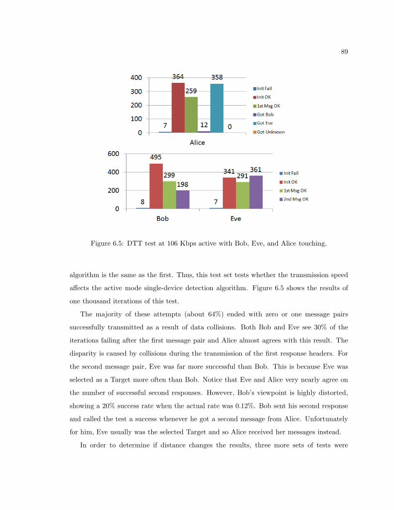
89
Figure 6.5: DTT test at 106 Kbps active with Bob, Eve, and Alice touching.
algorithm is the same as the first. Thus, this test set tests whether the transmission speed
affects the active mode single-device detection algorithm. Figure 6.5 shows the results of
one thousand iterations of this test.
The majority of these attempts (about 64%) ended with zero or one message pairs
successfully transmitted as a result of data collisions. Both Bob and Eve see 30% of the
iterations failing after the first message pair and Alice almost agrees with this result. The
disparity is caused by collisions during the transmission of the first response headers. For
the second message pair, Eve was far more successful than Bob. This is because Eve was
selected as a Target more often than Bob. Notice that Eve and Alice very nearly agree on
the number of successful second responses. However, Bob’s viewpoint is highly distorted,
showing a 20% success rate when the actual rate was 0.12%. Bob sent his second response
and called the test a success whenever he got a second message from Alice. Unfortunately
for him, Eve usually was the selected Target and so Alice received her messages instead.
In order to determine if distance changes the results, three more sets of tests were
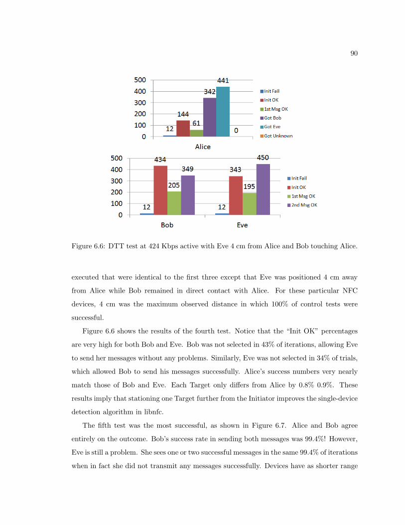
90
Figure 6.6: DTT test at 424 Kbps active with Eve 4 cm from Alice and Bob touching Alice.
executed that were identical to the first three except that Eve was positioned 4 cm away
from Alice while Bob remained in direct contact with Alice. For these particular NFC
devices, 4 cm was the maximum observed distance in which 100% of control tests were
successful.
Figure 6.6 shows the results of the fourth test. Notice that the “Init OK” percentages
are very high for both Bob and Eve. Bob was not selected in 43% of iterations, allowing Eve
to send her messages without any problems. Similarly, Eve was not selected in 34% of trials,
which allowed Bob to send his messages successfully. Alice’s success numbers very nearly
match those of Bob and Eve. Each Target only differs from Alice by 0.8% 0.9%. These
results imply that stationing one Target further from the Initiator improves the single-device
detection algorithm in libnfc.
The fifth test was the most successful, as shown in Figure 6.7. Alice and Bob agree
entirely on the outcome. Bob’s success rate in sending both messages was 99.4%! However,
Eve is still a problem. She sees one or two successful messages in the same 99.4% of iterations
when in fact she did not transmit any messages successfully. Devices have as shorter range
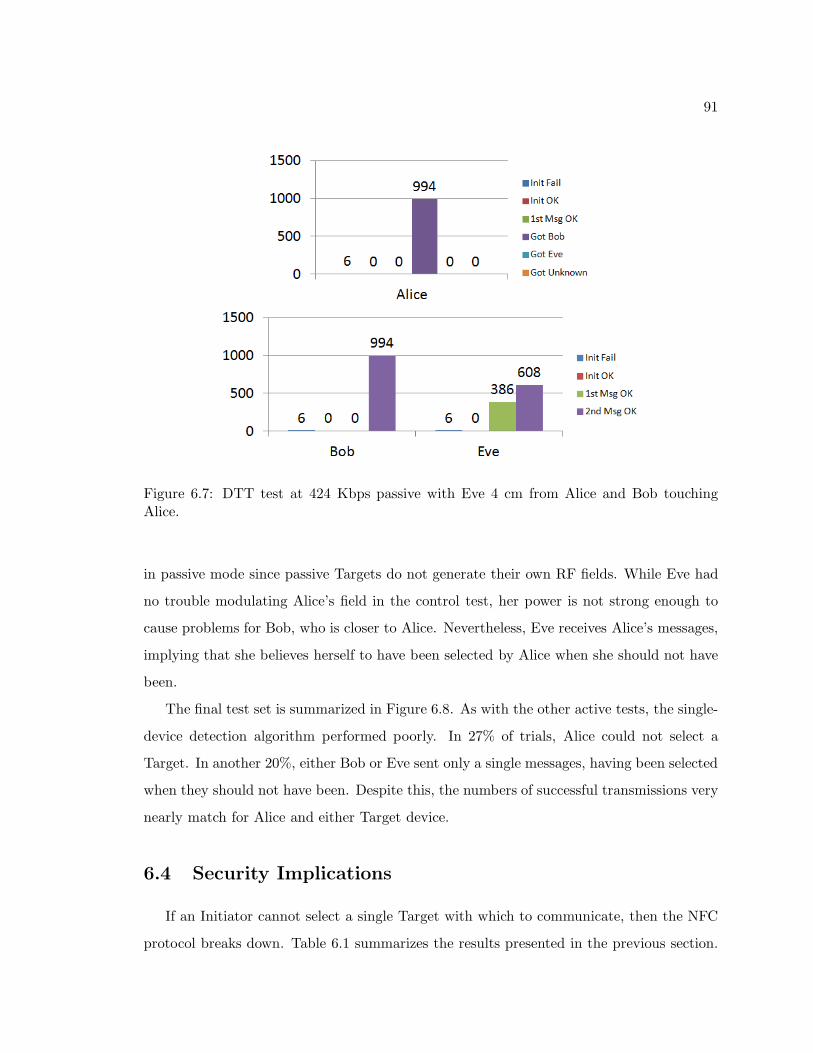
91
Figure 6.7: DTT test at 424 Kbps passive with Eve 4 cm from Alice and Bob touchingAlice.
in passive mode since passive Targets do not generate their own RF fields. While Eve had
no trouble modulating Alice’s field in the control test, her power is not strong enough to
cause problems for Bob, who is closer to Alice. Nevertheless, Eve receives Alice’s messages,
implying that she believes herself to have been selected by Alice when she should not have
been.
The final test set is summarized in Figure 6.8. As with the other active tests, the single-
device detection algorithm performed poorly. In 27% of trials, Alice could not select a
Target. In another 20%, either Bob or Eve sent only a single messages, having been selected
when they should not have been. Despite this, the numbers of successful transmissions very
nearly match for Alice and either Target device.
6.4 Security Implications
If an Initiator cannot select a single Target with which to communicate, then the NFC
protocol breaks down. Table 6.1 summarizes the results presented in the previous section.
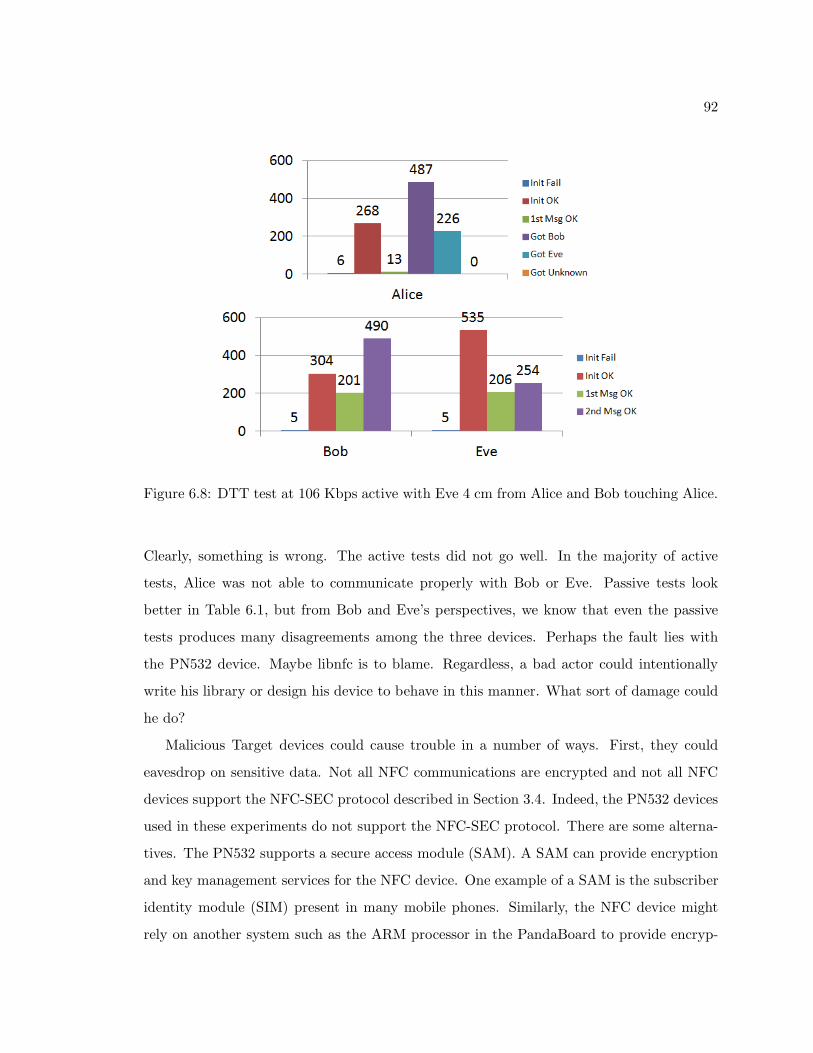
92
Figure 6.8: DTT test at 106 Kbps active with Eve 4 cm from Alice and Bob touching Alice.
Clearly, something is wrong. The active tests did not go well. In the majority of active
tests, Alice was not able to communicate properly with Bob or Eve. Passive tests look
better in Table 6.1, but from Bob and Eve’s perspectives, we know that even the passive
tests produces many disagreements among the three devices. Perhaps the fault lies with
the PN532 device. Maybe libnfc is to blame. Regardless, a bad actor could intentionally
write his library or design his device to behave in this manner. What sort of damage could
he do?
Malicious Target devices could cause trouble in a number of ways. First, they could
eavesdrop on sensitive data. Not all NFC communications are encrypted and not all NFC
devices support the NFC-SEC protocol described in Section 3.4. Indeed, the PN532 devices
used in these experiments do not support the NFC-SEC protocol. There are some alterna-
tives. The PN532 supports a secure access module (SAM). A SAM can provide encryption
and key management services for the NFC device. One example of a SAM is the subscriber
identity module (SIM) present in many mobile phones. Similarly, the NFC device might
rely on another system such as the ARM processor in the PandaBoard to provide encryp-
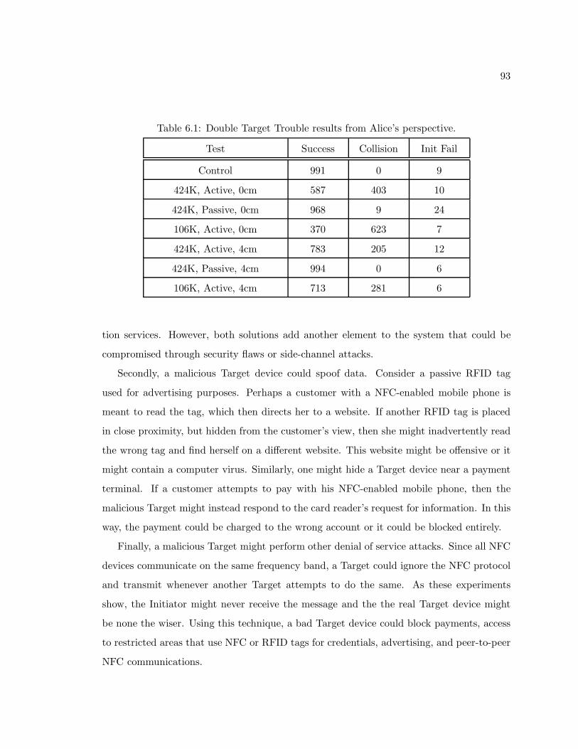
93
Table 6.1: Double Target Trouble results from Alice’s perspective.
Test Success Collision Init Fail
Control 991 0 9
424K, Active, 0cm 587 403 10
424K, Passive, 0cm 968 9 24
106K, Active, 0cm 370 623 7
424K, Active, 4cm 783 205 12
424K, Passive, 4cm 994 0 6
106K, Active, 4cm 713 281 6
tion services. However, both solutions add another element to the system that could be
compromised through security flaws or side-channel attacks.
Secondly, a malicious Target device could spoof data. Consider a passive RFID tag
used for advertising purposes. Perhaps a customer with a NFC-enabled mobile phone is
meant to read the tag, which then directs her to a website. If another RFID tag is placed
in close proximity, but hidden from the customer’s view, then she might inadvertently read
the wrong tag and find herself on a different website. This website might be offensive or it
might contain a computer virus. Similarly, one might hide a Target device near a payment
terminal. If a customer attempts to pay with his NFC-enabled mobile phone, then the
malicious Target might instead respond to the card reader’s request for information. In this
way, the payment could be charged to the wrong account or it could be blocked entirely.
Finally, a malicious Target might perform other denial of service attacks. Since all NFC
devices communicate on the same frequency band, a Target could ignore the NFC protocol
and transmit whenever another Target attempts to do the same. As these experiments
show, the Initiator might never receive the message and the the real Target device might
be none the wiser. Using this technique, a bad Target device could block payments, access
to restricted areas that use NFC or RFID tags for credentials, advertising, and peer-to-peer
NFC communications.

94
6.5 Chapter Summary
This chapter presented an experiment that showed what happens when NFC Target
devices do not follow the NFC protocol. Whether by accident or intentionally, a bad Target
device could eavesdrop on sensitive data, spoof data, and deny service to legitimate devices.
While encryption can alleviate the first problem and more advanced security services can
somewhat alleviate the second, neither is effective against the third type of attack. Further,
not all devices are suitable for encryption. For instance, one would not wish to forget his
private key when accessing critical medical sensor information.
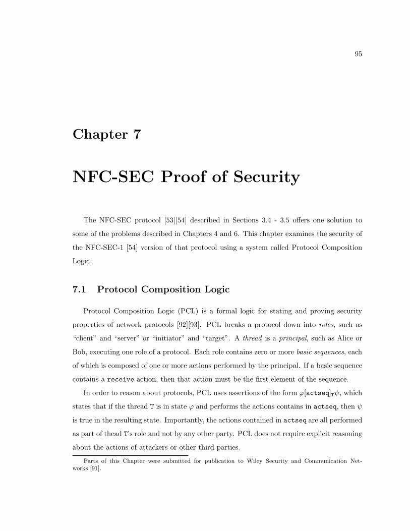
95
Chapter 7
NFC-SEC Proof of Security
The NFC-SEC protocol [53][54] described in Sections 3.4 - 3.5 offers one solution to
some of the problems described in Chapters 4 and 6. This chapter examines the security of
the NFC-SEC-1 [54] version of that protocol using a system called Protocol Composition
Logic.
7.1 Protocol Composition Logic
Protocol Composition Logic (PCL) is a formal logic for stating and proving security
properties of network protocols [92][93]. PCL breaks a protocol down into roles, such as
“client” and “server” or “initiator” and “target”. A thread is a principal, such as Alice or
Bob, executing one role of a protocol. Each role contains zero or more basic sequences, each
of which is composed of one or more actions performed by the principal. If a basic sequence
contains a receive action, then that action must be the first element of the sequence.
In order to reason about protocols, PCL uses assertions of the form ϕ[actseq]Tψ, which
states that if the thread T is in state ϕ and performs the actions contains in actseq, then ψ
is true in the resulting state. Importantly, the actions contained in actseq are all performed
as part of thead T’s role and not by any other party. PCL does not require explicit reasoning
about the actions of attackers or other third parties.
Parts of this Chapter were submitted for publication to Wiley Security and Communication Net-works [91].
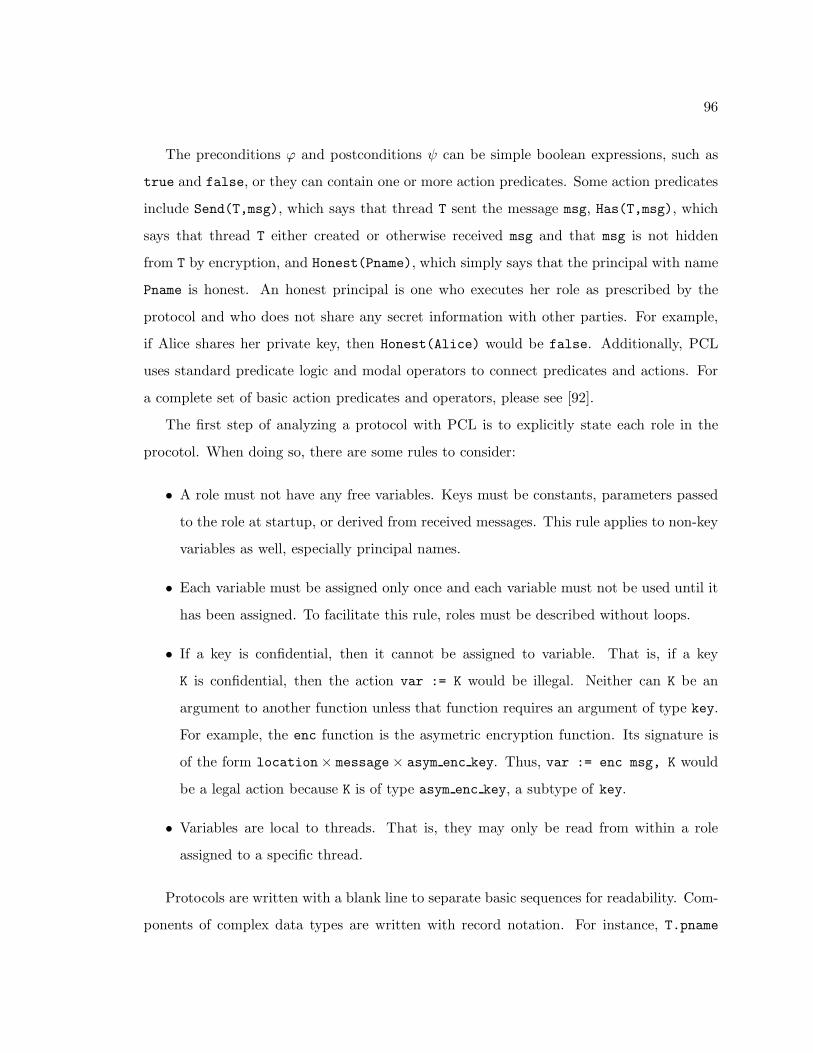
96
The preconditions ϕ and postconditions ψ can be simple boolean expressions, such as
true and false, or they can contain one or more action predicates. Some action predicates
include Send(T,msg), which says that thread T sent the message msg, Has(T,msg), which
says that thread T either created or otherwise received msg and that msg is not hidden
from T by encryption, and Honest(Pname), which simply says that the principal with name
Pname is honest. An honest principal is one who executes her role as prescribed by the
protocol and who does not share any secret information with other parties. For example,
if Alice shares her private key, then Honest(Alice) would be false. Additionally, PCL
uses standard predicate logic and modal operators to connect predicates and actions. For
a complete set of basic action predicates and operators, please see [92].
The first step of analyzing a protocol with PCL is to explicitly state each role in the
procotol. When doing so, there are some rules to consider:
• A role must not have any free variables. Keys must be constants, parameters passed
to the role at startup, or derived from received messages. This rule applies to non-key
variables as well, especially principal names.
• Each variable must be assigned only once and each variable must not be used until it
has been assigned. To facilitate this rule, roles must be described without loops.
• If a key is confidential, then it cannot be assigned to variable. That is, if a key
K is confidential, then the action var := K would be illegal. Neither can K be an
argument to another function unless that function requires an argument of type key.
For example, the enc function is the asymetric encryption function. Its signature is
of the form location× message× asym enc key. Thus, var := enc msg, K would
be a legal action because K is of type asym enc key, a subtype of key.
• Variables are local to threads. That is, they may only be read from within a role
assigned to a specific thread.
Protocols are written with a blank line to separate basic sequences for readability. Com-
ponents of complex data types are written with record notation. For instance, T.pname
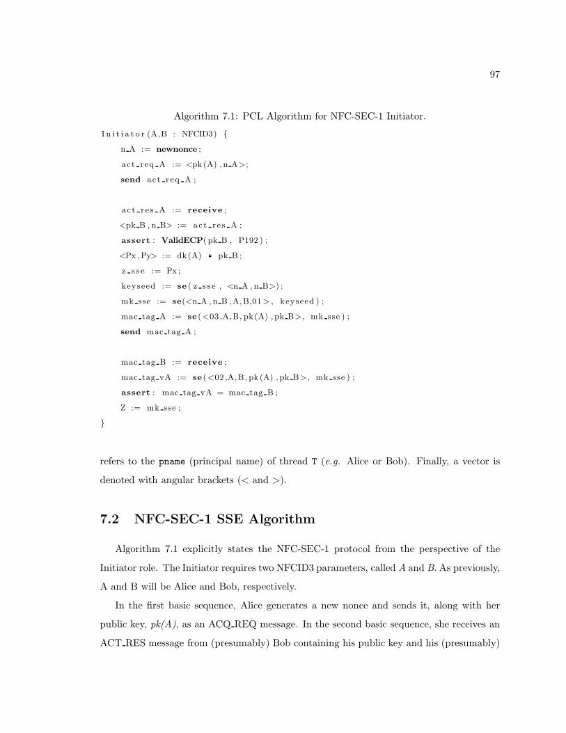
97
Algorithm 7.1: PCL Algorithm for NFC-SEC-1 Initiator.
I n i t i a t o r (A,B : NFCID3) {
n A := newnonce ;
act req A := <pk (A) ,n A>;
send act req A ;
ac t r e s A := receive ;
<pk B , n B> := act r e s A ;
assert : ValidECP( pk B , P192 ) ;
<Px ,Py> := dk(A) * pk B ;
z s s e := Px ;
keyseed := se ( z s s e , <n A , n B>) ;
mk sse := se(<n A , n B ,A,B,01> , keyseed ) ;
mac tag A := se (<03 ,A,B, pk (A) , pk B>, mk sse ) ;
send mac tag A ;
mac tag B := receive ;
mac tag vA := se (<02 ,A,B, pk (A) , pk B>, mk sse ) ;
assert : mac tag vA = mac tag B ;
Z := mk sse ;
}
refers to the pname (principal name) of thread T (e.g. Alice or Bob). Finally, a vector is
denoted with angular brackets (< and >).
7.2 NFC-SEC-1 SSE Algorithm
Algorithm 7.1 explicitly states the NFC-SEC-1 protocol from the perspective of the
Initiator role. The Initiator requires two NFCID3 parameters, called A and B. As previously,
A and B will be Alice and Bob, respectively.
In the first basic sequence, Alice generates a new nonce and sends it, along with her
public key, pk(A), as an ACQ REQ message. In the second basic sequence, she receives an
ACT RES message from (presumably) Bob containing his public key and his (presumably)
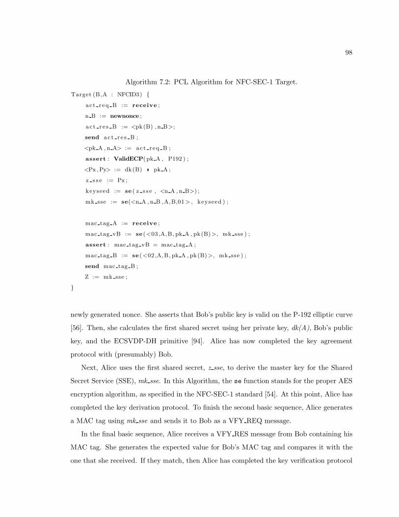
98
Algorithm 7.2: PCL Algorithm for NFC-SEC-1 Target.
Target (B,A : NFCID3) {
ac t r eq B := receive ;
n B := newnonce ;
a c t r e s B := <pk (B) , n B>;
send ac t r e s B ;
<pk A , n A> := act r eq B ;
assert : ValidECP(pk A , P192 ) ;
<Px ,Py> := dk(B) * pk A ;
z s s e := Px ;
keyseed := se ( z s s e , <n A , n B>) ;
mk sse := se(<n A , n B ,A,B,01> , keyseed ) ;
mac tag A := receive ;
mac tag vB := se (<03 ,A,B, pk A , pk (B)>, mk sse ) ;
assert : mac tag vB = mac tag A ;
mac tag B := se (<02 ,A,B, pk A , pk (B)>, mk sse ) ;
send mac tag B ;
Z := mk sse ;
}
newly generated nonce. She asserts that Bob’s public key is valid on the P-192 elliptic curve
[56]. Then, she calculates the first shared secret using her private key, dk(A), Bob’s public
key, and the ECSVDP-DH primitive [94]. Alice has now completed the key agreement
protocol with (presumably) Bob.
Next, Alice uses the first shared secret, z sse, to derive the master key for the Shared
Secret Service (SSE), mk sse. In this Algorithm, the se function stands for the proper AES
encryption algorithm, as specified in the NFC-SEC-1 standard [54]. At this point, Alice has
completed the key derivation protocol. To finish the second basic sequence, Alice generates
a MAC tag using mk sse and sends it to Bob as a VFY REQ message.
In the final basic sequence, Alice receives a VFY RES message from Bob containing his
MAC tag. She generates the expected value for Bob’s MAC tag and compares it with the
one that she received. If they match, then Alice has completed the key verification protocol
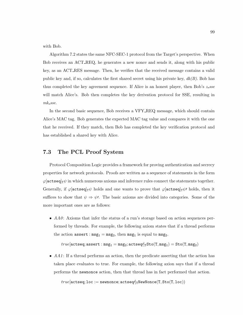
99
with Bob.
Algorithm 7.2 states the same NFC-SEC-1 protocol from the Target’s perspective. When
Bob receives an ACT REQ, he generates a new nonce and sends it, along with his public
key, as an ACT RES message. Then, he verifies that the received message contains a valid
public key and, if so, calculates the first shared secret using his private key, dk(B). Bob has
thus completed the key agreement sequence. If Alice is an honest player, then Bob’s z sse
will match Alice’s. Bob then completes the key derivation protocol for SSE, resulting in
mk sse.
In the second basic sequence, Bob receives a VFY REQ message, which should contain
Alice’s MAC tag. Bob generates the expected MAC tag value and compares it with the one
that he received. If they match, then Bob has completed the key verification protocol and
has established a shared key with Alice.
7.3 The PCL Proof System
Protocol Composition Logic provides a framework for proving authentication and secrecy
properties for network protocols. Proofs are written as a sequence of statements in the form
ϕ[actseq]Tψ in which numerous axioms and inference rules connect the statements together.
Generally, if ϕ[actseq]Tψ holds and one wants to prove that ϕ[actseq]Tψ′ holds, then it
suffices to show that ψ ⇒ ψ′. The basic axioms are divided into categories. Some of the
more important ones are as follows:
• AA0 : Axioms that infer the status of a run’s storage based on action sequences per-
formed by threads. For example, the following axiom states that if a thread performs
the action assert : msg1 = msg2, then msg1 is equal to msg2.
true[actseq; assert : msg1 = msg2; actseq′]TSto(T, msg1) = Sto(T, msg2)
• AA1 : If a thread performs an action, then the predicate asserting that the action has
taken place evaluates to true. For example, the following axion says that if a thread
performs the newnonce action, then that thread has in fact performed that action.
true[actseq; loc := newnonce; actseq′]TNewNonce(T, Sto(T, loc))
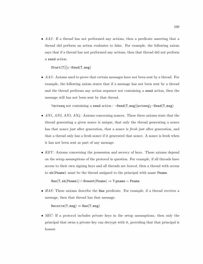
100
• AA2 : If a thread has not performed any actions, then a predicate asserting that a
thread did perform an action evaluates to false. For example, the following axiom
says that if a thread has not performed any actions, then that thread did not perform
a send action.
Start(T)[]T¬Send(T, msg)
• AA3 : Axioms used to prove that certain messages have not been sent by a thread. For
example, the following axiom states that if a message has not been sent by a thread
and the thread performs any action sequence not containing a send action, then the
message still has not been sent by that thread.
∀actseq not containing a send action : ¬Send(T, msg)[actseq]T¬Send(T, msg)
• AN1, AN2, AN3, AN4 : Axioms concerning nonces. These three axioms state that the
thread generating a given nonce is unique, that only the thread generating a nonce
has that nonce just after generation, that a nonce is fresh just after generation, and
that a thread only has a fresh nonce if it generated that nonce. A nonce is fresh when
it has not been sent as part of any message.
• KEY : Axioms concerning the possession and secrecy of keys. These axioms depend
on the setup assumptions of the protocol in question. For example, if all threads have
access to their own signing keys and all threads are honest, then a thread with access
to sk(Pname) must be the thread assigned to the principal with name Pname.
Has(T, sk(Pname)) ∧ Honest(Pname) ⇒ T.pname = Pname
• HAS : These axioms describe the Has predicate. For example, if a thread receives a
message, then that thread has that message.
Receive(T, msg) ⇒ Has(T, msg)
• SEC : If a protocol includes private keys in the setup assumptions, then only the
principal that owns a private key can decrypt with it, providing that that principal is
honest.
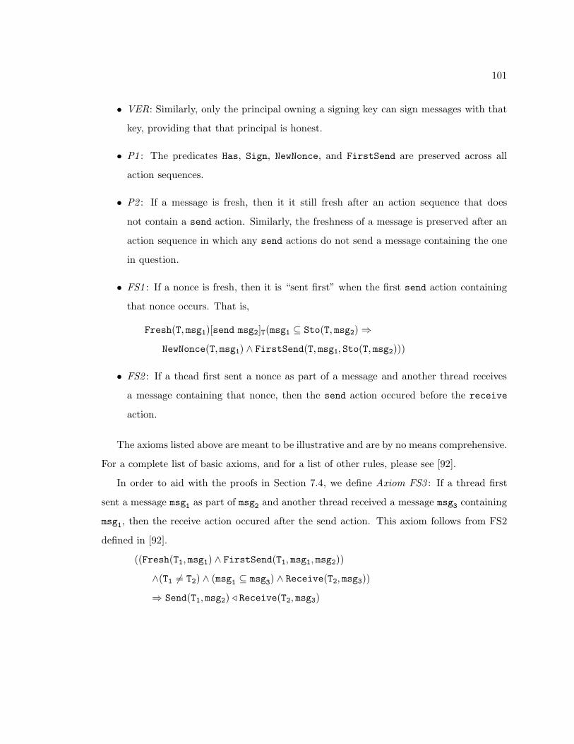
101
• VER: Similarly, only the principal owning a signing key can sign messages with that
key, providing that that principal is honest.
• P1 : The predicates Has, Sign, NewNonce, and FirstSend are preserved across all
action sequences.
• P2 : If a message is fresh, then it it still fresh after an action sequence that does
not contain a send action. Similarly, the freshness of a message is preserved after an
action sequence in which any send actions do not send a message containing the one
in question.
• FS1 : If a nonce is fresh, then it is “sent first” when the first send action containing
that nonce occurs. That is,
Fresh(T, msg1)[send msg2]T(msg1 ⊆ Sto(T, msg2) ⇒
NewNonce(T, msg1) ∧ FirstSend(T, msg1, Sto(T, msg2)))
• FS2 : If a thead first sent a nonce as part of a message and another thread receives
a message containing that nonce, then the send action occured before the receive
action.
The axioms listed above are meant to be illustrative and are by no means comprehensive.
For a complete list of basic axioms, and for a list of other rules, please see [92].
In order to aid with the proofs in Section 7.4, we define Axiom FS3 : If a thread first
sent a message msg1 as part of msg2 and another thread received a message msg3 containing
msg1, then the receive action occured after the send action. This axiom follows from FS2
defined in [92].
((Fresh(T1, msg1) ∧ FirstSend(T1, msg1, msg2))
∧(T1 6= T2) ∧ (msg1 ⊆ msg3) ∧ Receive(T2, msg3))
⇒ Send(T1, msg2) ⊳ Receive(T2, msg3)
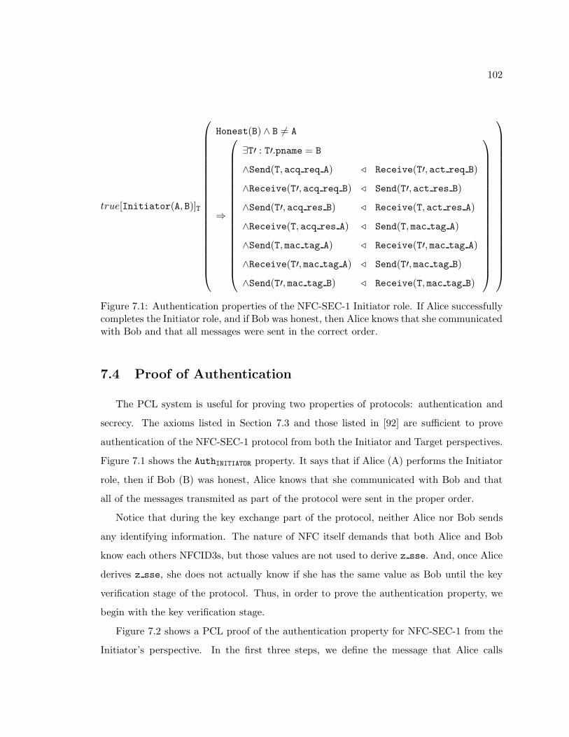
102
true[Initiator(A, B)]T
Honest(B) ∧ B 6= A
⇒
∃T′ : T′.pname = B
∧Send(T, acq req A) ⊳ Receive(T′, act req B)
∧Receive(T′, acq req B) ⊳ Send(T′, act res B)
∧Send(T′, acq res B) ⊳ Receive(T, act res A)
∧Receive(T, acq res A) ⊳ Send(T, mac tag A)
∧Send(T, mac tag A) ⊳ Receive(T′, mac tag A)
∧Receive(T′, mac tag A) ⊳ Send(T′, mac tag B)
∧Send(T′, mac tag B) ⊳ Receive(T, mac tag B)
Figure 7.1: Authentication properties of the NFC-SEC-1 Initiator role. If Alice successfullycompletes the Initiator role, and if Bob was honest, then Alice knows that she communicatedwith Bob and that all messages were sent in the correct order.
7.4 Proof of Authentication
The PCL system is useful for proving two properties of protocols: authentication and
secrecy. The axioms listed in Section 7.3 and those listed in [92] are sufficient to prove
authentication of the NFC-SEC-1 protocol from both the Initiator and Target perspectives.
Figure 7.1 shows the AuthINITIATOR property. It says that if Alice (A) performs the Initiator
role, then if Bob (B) was honest, Alice knows that she communicated with Bob and that
all of the messages transmited as part of the protocol were sent in the proper order.
Notice that during the key exchange part of the protocol, neither Alice nor Bob sends
any identifying information. The nature of NFC itself demands that both Alice and Bob
know each others NFCID3s, but those values are not used to derive z sse. And, once Alice
derives z sse, she does not actually know if she has the same value as Bob until the key
verification stage of the protocol. Thus, in order to prove the authentication property, we
begin with the key verification stage.
Figure 7.2 shows a PCL proof of the authentication property for NFC-SEC-1 from the
Initiator’s perspective. In the first three steps, we define the message that Alice calls
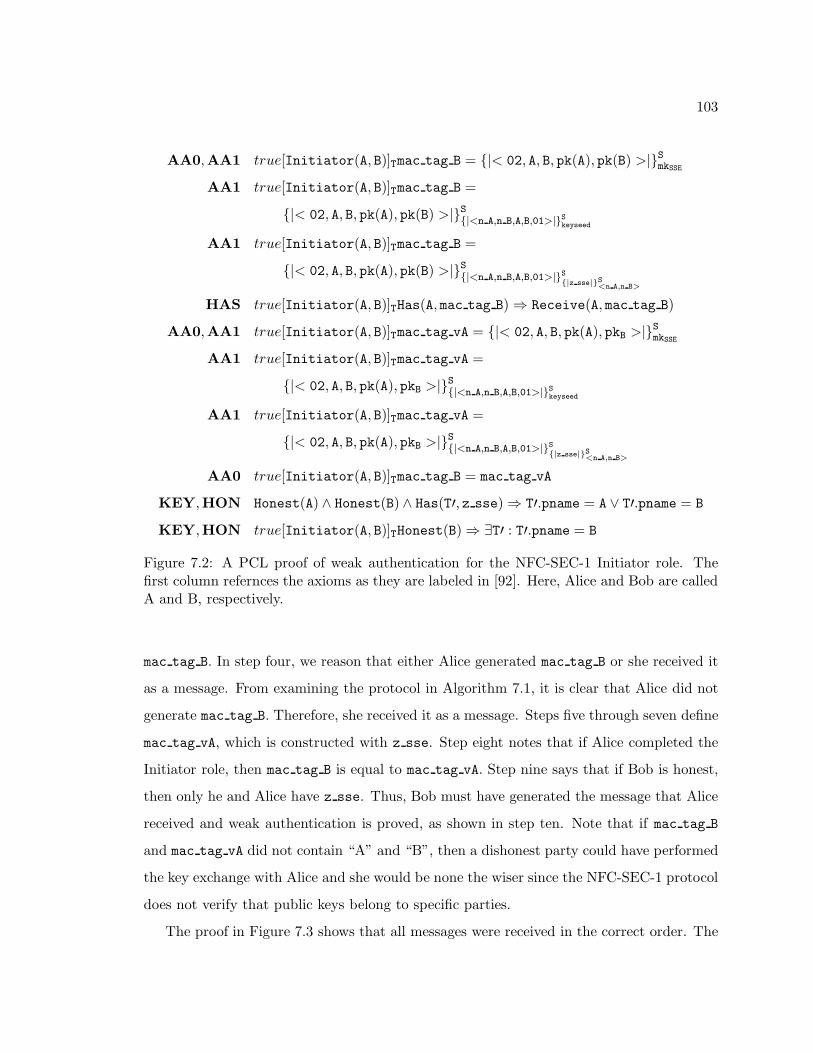
103
AA0,AA1 true[Initiator(A, B)]Tmac tag B = {|< 02, A, B, pk(A), pk(B) >|}SmkSSE
AA1 true[Initiator(A, B)]Tmac tag B =
{|< 02, A, B, pk(A), pk(B) >|}S{|<n A,n B,A,B,01>|}Skeyseed
AA1 true[Initiator(A, B)]Tmac tag B =
{|< 02, A, B, pk(A), pk(B) >|}S{|<n A,n B,A,B,01>|}S{|z sse|}S
<n A,n B>
HAS true[Initiator(A, B)]THas(A, mac tag B) ⇒ Receive(A, mac tag B)
AA0,AA1 true[Initiator(A, B)]Tmac tag vA = {|< 02, A, B, pk(A), pkB >|}SmkSSE
AA1 true[Initiator(A, B)]Tmac tag vA =
{|< 02, A, B, pk(A), pkB >|}S
{|<n A,n B,A,B,01>|}Skeyseed
AA1 true[Initiator(A, B)]Tmac tag vA =
{|< 02, A, B, pk(A), pkB >|}S
{|<n A,n B,A,B,01>|}S{|z sse|}S
<n A,n B>
AA0 true[Initiator(A, B)]Tmac tag B = mac tag vA
KEY,HON Honest(A) ∧ Honest(B) ∧ Has(T′, z sse) ⇒ T′.pname = A ∨ T′.pname = B
KEY,HON true[Initiator(A, B)]THonest(B) ⇒ ∃T′ : T′.pname = B
Figure 7.2: A PCL proof of weak authentication for the NFC-SEC-1 Initiator role. Thefirst column refernces the axioms as they are labeled in [92]. Here, Alice and Bob are calledA and B, respectively.
mac tag B. In step four, we reason that either Alice generated mac tag B or she received it
as a message. From examining the protocol in Algorithm 7.1, it is clear that Alice did not
generate mac tag B. Therefore, she received it as a message. Steps five through seven define
mac tag vA, which is constructed with z sse. Step eight notes that if Alice completed the
Initiator role, then mac tag B is equal to mac tag vA. Step nine says that if Bob is honest,
then only he and Alice have z sse. Thus, Bob must have generated the message that Alice
received and weak authentication is proved, as shown in step ten. Note that if mac tag B
and mac tag vA did not contain “A” and “B”, then a dishonest party could have performed
the key exchange with Alice and she would be none the wiser since the NFC-SEC-1 protocol
does not verify that public keys belong to specific parties.
The proof in Figure 7.3 shows that all messages were received in the correct order. The
104
first step says that if Alice generated a fresh nonce and sent a message containing it, and
then Bob received a message containing that nonce, then Alice sent her message before Bob
received his. Observation of the protocol shows that Bob receives act req B before sending
act res B. Likewise, Bob must have sent his new nonce before Alice received it and, by
observation, Alice must have received act res A before sending mac tag A.
The second step uses the new FS3 axiom to show that since mac tag A was Fresh before
Alice sent it, then she must have sent it before Bob received it. Observation of the protocol
and a second application of FS3 show that the final message, mac tag B was sent and
received in the proper order, thus proving strong authentication.
Since the Initiator and Target perform essentially the same functions in the NFC-SEC-1
protocol, the AuthTARGET property would look very similar to AuthINITIATOR in Figure 7.1 and
the proofs of authentication would be nearly identical to the ones in Figures 7.2 and 7.3.
7.5 Chapter Summary
Protocol Composition Logic (PCL) provides a framework for proving the security prop-
erties of network protocols. In this chapter, PCL is used to provide a proof of the au-
thentication property of the NFC-SEC-1 protocol’s Shared Secret Service (SSE) from the
perspectives of both the Initiator and Target devices.
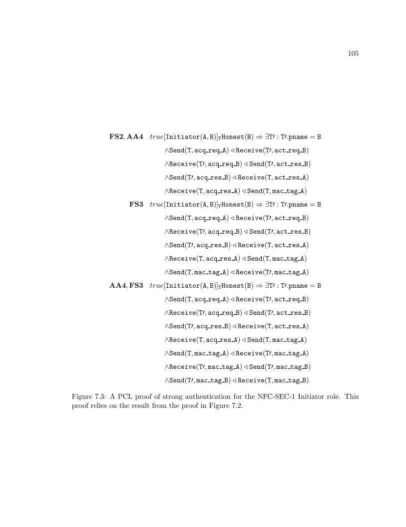
105
FS2,AA4 true[Initiator(A, B)]THonest(B) ⇒ ∃T′ : T′.pname = B
∧Send(T, acq req A) ⊳ Receive(T′, act req B)
∧Receive(T′, acq req B) ⊳ Send(T′, act res B)
∧Send(T′, acq res B) ⊳ Receive(T, act res A)
∧Receive(T, acq res A) ⊳ Send(T, mac tag A)
FS3 true[Initiator(A, B)]THonest(B) ⇒ ∃T′ : T′.pname = B
∧Send(T, acq req A) ⊳ Receive(T′, act req B)
∧Receive(T′, acq req B) ⊳ Send(T′, act res B)
∧Send(T′, acq res B) ⊳ Receive(T, act res A)
∧Receive(T, acq res A) ⊳ Send(T, mac tag A)
∧Send(T, mac tag A) ⊳ Receive(T′, mac tag A)
AA4,FS3 true[Initiator(A, B)]THonest(B) ⇒ ∃T′ : T′.pname = B
∧Send(T, acq req A) ⊳ Receive(T′, act req B)
∧Receive(T′, acq req B) ⊳ Send(T′, act res B)
∧Send(T′, acq res B) ⊳ Receive(T, act res A)
∧Receive(T, acq res A) ⊳ Send(T, mac tag A)
∧Send(T, mac tag A) ⊳ Receive(T′, mac tag A)
∧Receive(T′, mac tag A) ⊳ Send(T′, mac tag B)
∧Send(T′, mac tag B) ⊳ Receive(T, mac tag B)
Figure 7.3: A PCL proof of strong authentication for the NFC-SEC-1 Initiator role. Thisproof relies on the result from the proof in Figure 7.2.
106
Chapter 8
Conclusions
8.1 Summary and Accomplishments
As Near Field Communication (NFC) technology matures, it will increasingly become
part of daily commerce. Therefore, NFC transactions must be as secure as possible. This
dissertation examined the known weaknesses of NFC technology, such as eavesdropping
attacks and relay attacks, as well as its inherent defenses, such as its short communication
range.
A new test and development platform utilizing a combination of commercial, off-the-
shelf components will allow future researchers and engineers to find weaknesses in NFC
protocols and to develop defenses against them. This new test platform uses hardware that
is very similar to that found in typical smart phones and which is compatible with nearly
all other NFC and RFID devices currently on the market. All of the hardware and software
comprising the new test and development platform is open source, enabling future users to
modify it as necessary.
Using the new test platform, this dissertation presented a situation in which the single-
device detection protocol failed to ensure a proper pairing of NFC devices. This failure
leaves NFC transactions open to bad actors and is easily reproduced. One possible defense
against this problem is the NFC-SEC protocol, which provides for secure key exchanges and
encrypted datagrams.
107
The NFC-SEC protocol itself specifies only a framework for security services. The more
specific NFC-SEC-1 protocol provides the details, including elliptic curve Diffie-Hellman
key exchanges and AES data encryption. Using a framework called Protocol Composition
Logic, this dissertation examined the NFC-SEC-1 protocol and proved that it is sound for
authentication purposes. With NFC-SEC-1, two honest actors can ensure that they are
communicating with one another and that all of their messages are sent and received in the
correct order, regardless of any attackers.
8.2 Future Work
While the NFC-SEC protocol is sufficient to secure some NFC transactions, others
cannot benefit from its services. Even then NFC-SEC is employed, security might not be
sufficient. Therefore, further research with the test and developoment platform and other
test equipment is necessary to improve the security of NFC technology. Some possible areas
of exploration include:
• Prove the secrecy properties of NFC-SEC-1 with PCL. While this dissertation was able
to show that NFC-SEC-1 provides proper authentication services, it did not attempt
to show that the protocol provides secrecy of data. Proving the secrecy properties of
NFC-SEC-1 is essential to understanding it.
• Fix the double target problem. Whether the result of a bug in the libnfc software or
a flaw in the PN532 module, the double target problem is easily reproducable and
could cause significant interference for legitimate transactions. Therefore, a fix for the
single-device detection protocol to migitate this problem would be beneficial.
• Update the test and development platform. Adding additional NFC devices, including
some that employ the NFC-SEC protocol, would allow developers to test vulnerabili-
ties and defenses in more realistic situations. Many NFC readers use a standard USB
interface, which the test platform provides. Additionally, the test platform currently
runs a somewhat outdated version of Ubuntu Linux. Future iterations of the platform
108
might use a newer release or switch to the Android operating system to better emulate
current smart phones.
• Improve the libnfc library. The libnfc library is both free and open source and sup-
ports a large selection of NFC and RFID devices. While it does an adequate job of
implementing low-level device drivers, it lacks higher-level interfaces for easily sending
NFC messages in raw or NDEF format. Further, the library appears to be lacking
full support for the PN533 device’s NFC-SEC features. Improvements to libnfc would
benefit all NFC developers and researchers.
8.3 Resulting Publications
• Steven J. Olivieri, Nicholas A. F. DeMarinis, Alexander M. Wyglinski. “On Protocol
Architectures for Near Field Communication Systems: An Overview.” Wiley Journal
on Wireless Communications and Networks, April 2015 (Submitted).
• Steven J. Olivieri, Nicholas A. F. DeMarinis, Alexander M. Wyglinski. “A Tutorial on
Near Field Communication Security Protocols.” Elsevier Computer Communications,
April 2015 (Submitted).
• Steven J. Olivieri, Nicholas A. F. DeMarinis, Alexander M. Wyglinski. “Analyzing
NFC-SEC with Protocol Composition Logic.” Wiley Security and Communication
Networks, April 2015 (Submitted).
109
Appendix A
Multiplying in Finite Fields
The peasant algorithm is an ancient form of multiplication that was used in at least
Egypt, Russia, and Ehtiopia. It allows one to multiply two numbers using only doubling,
halving, and summing. Thus, it was easier to learn than multiplication tables and methods
that we use today.
A.1 Peasant Algorithm
To begin, determine the two multiplicands. As an example, let us use 327 and 15. Next,
decompose the larger of the two multiplicands. To do so, first find the largest power of two
in the larger of the two multiplicands. Begin with the number 1 and multiply by 2 until
the result is larger than the multiplicand.
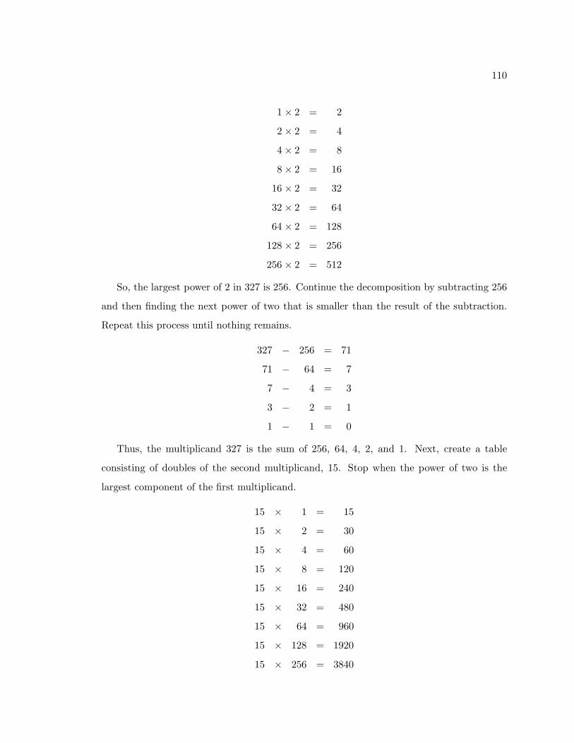
110
1× 2 = 2
2× 2 = 4
4× 2 = 8
8× 2 = 16
16 × 2 = 32
32 × 2 = 64
64 × 2 = 128
128 × 2 = 256
256 × 2 = 512
So, the largest power of 2 in 327 is 256. Continue the decomposition by subtracting 256
and then finding the next power of two that is smaller than the result of the subtraction.
Repeat this process until nothing remains.
327 − 256 = 71
71 − 64 = 7
7 − 4 = 3
3 − 2 = 1
1 − 1 = 0
Thus, the multiplicand 327 is the sum of 256, 64, 4, 2, and 1. Next, create a table
consisting of doubles of the second multiplicand, 15. Stop when the power of two is the
largest component of the first multiplicand.
15 × 1 = 15
15 × 2 = 30
15 × 4 = 60
15 × 8 = 120
15 × 16 = 240
15 × 32 = 480
15 × 64 = 960
15 × 128 = 1920
15 × 256 = 3840
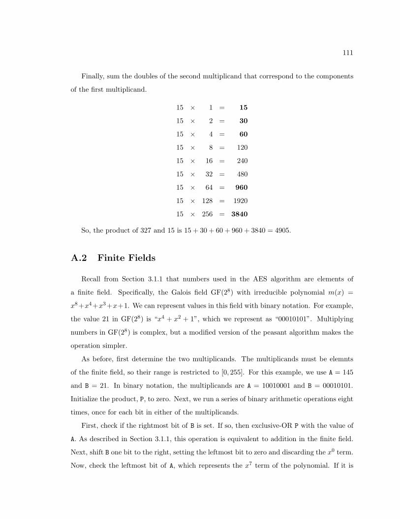
111
Finally, sum the doubles of the second multiplicand that correspond to the components
of the first multiplicand.
15 × 1 = 15
15 × 2 = 30
15 × 4 = 60
15 × 8 = 120
15 × 16 = 240
15 × 32 = 480
15 × 64 = 960
15 × 128 = 1920
15 × 256 = 3840
So, the product of 327 and 15 is 15 + 30 + 60 + 960 + 3840 = 4905.
A.2 Finite Fields
Recall from Section 3.1.1 that numbers used in the AES algorithm are elements of
a finite field. Specifically, the Galois field GF(28) with irreducible polynomial m(x) =
x8+x4+x3+x+1. We can represent values in this field with binary notation. For example,
the value 21 in GF(28) is “x4 + x2 + 1”, which we represent as “00010101”. Multiplying
numbers in GF(28) is complex, but a modified version of the peasant algorithm makes the
operation simpler.
As before, first determine the two multiplicands. The multiplicands must be elemnts
of the finite field, so their range is restricted to [0, 255]. For this example, we use A = 145
and B = 21. In binary notation, the multiplicands are A = 10010001 and B = 00010101.
Initialize the product, P, to zero. Next, we run a series of binary arithmetic operations eight
times, once for each bit in either of the multiplicands.
First, check if the rightmost bit of B is set. If so, then exclusive-OR P with the value of
A. As described in Section 3.1.1, this operation is equivalent to addition in the finite field.
Next, shift B one bit to the right, setting the leftmost bit to zero and discarding the x0 term.
Now, check the leftmost bit of A, which represents the x7 term of the polynomial. If it is
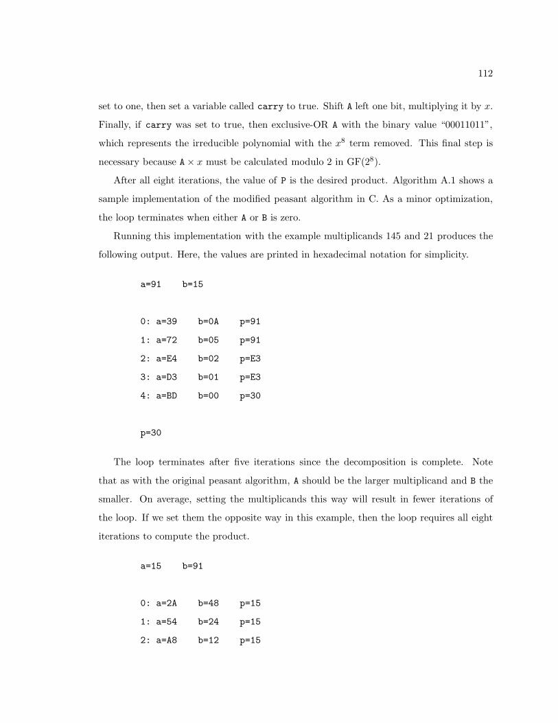
112
set to one, then set a variable called carry to true. Shift A left one bit, multiplying it by x.
Finally, if carry was set to true, then exclusive-OR A with the binary value “00011011”,
which represents the irreducible polynomial with the x8 term removed. This final step is
necessary because A× x must be calculated modulo 2 in GF(28).
After all eight iterations, the value of P is the desired product. Algorithm A.1 shows a
sample implementation of the modified peasant algorithm in C. As a minor optimization,
the loop terminates when either A or B is zero.
Running this implementation with the example multiplicands 145 and 21 produces the
following output. Here, the values are printed in hexadecimal notation for simplicity.
a=91 b=15
0: a=39 b=0A p=91
1: a=72 b=05 p=91
2: a=E4 b=02 p=E3
3: a=D3 b=01 p=E3
4: a=BD b=00 p=30
p=30
The loop terminates after five iterations since the decomposition is complete. Note
that as with the original peasant algorithm, A should be the larger multiplicand and B the
smaller. On average, setting the multiplicands this way will result in fewer iterations of
the loop. If we set them the opposite way in this example, then the loop requires all eight
iterations to compute the product.
a=15 b=91
0: a=2A b=48 p=15
1: a=54 b=24 p=15
2: a=A8 b=12 p=15
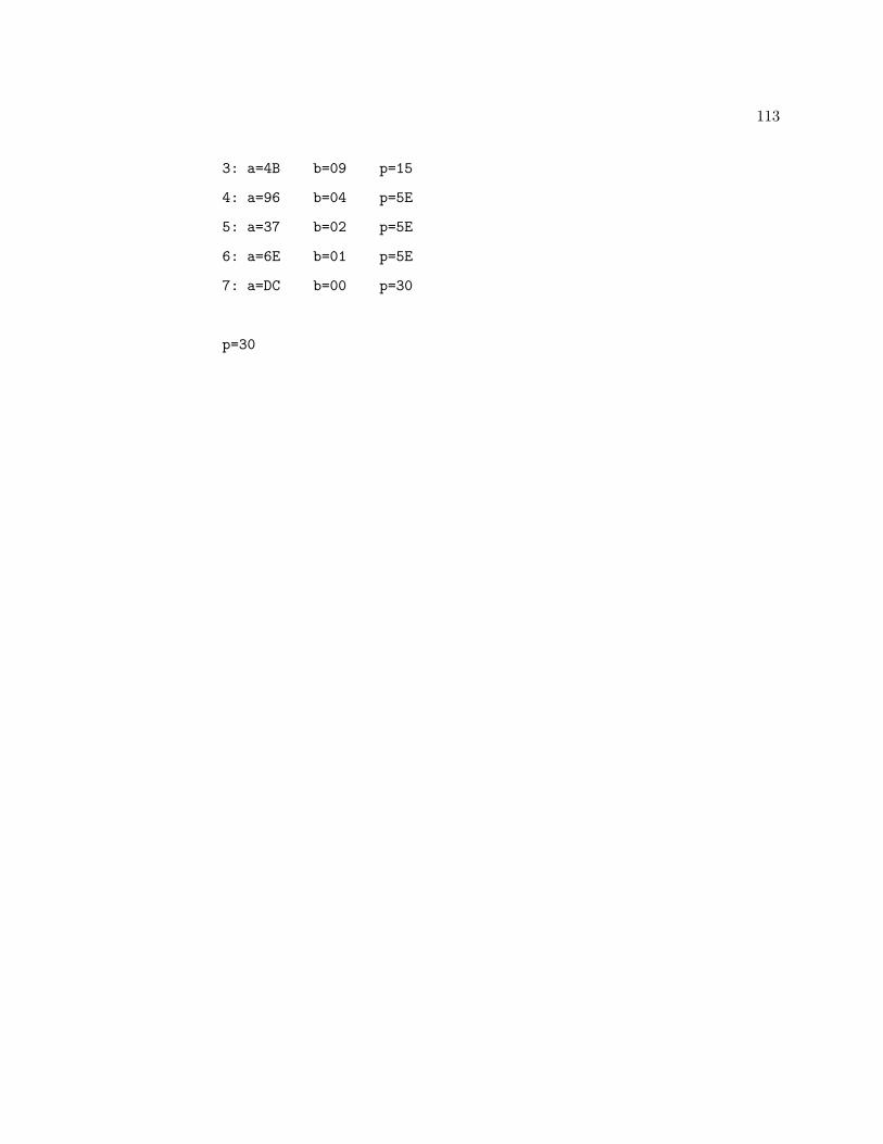
113
3: a=4B b=09 p=15
4: a=96 b=04 p=5E
5: a=37 b=02 p=5E
6: a=6E b=01 p=5E
7: a=DC b=00 p=30
p=30
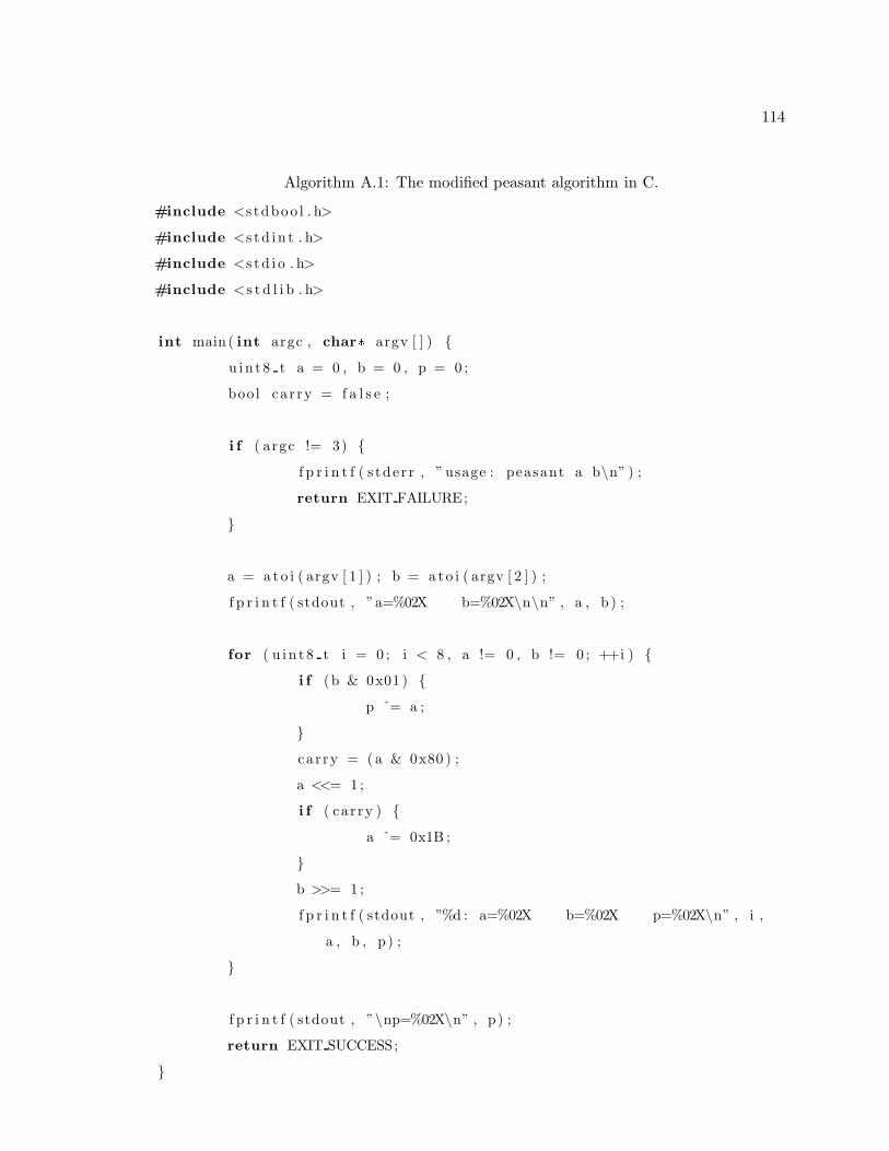
114
Algorithm A.1: The modified peasant algorithm in C.
#include <s tdboo l . h>
#include <s t d i n t . h>
#include <s t d i o . h>
#include <s t d l i b . h>
int main ( int argc , char* argv [ ] ) {
u in t 8 t a = 0 , b = 0 , p = 0 ;
bool car ry = f a l s e ;
i f ( argc != 3) {
f p r i n t f ( s tde r r , ” usage : peasant a b\n” ) ;
return EXIT FAILURE;
}
a = a to i ( argv [ 1 ] ) ; b = a to i ( argv [ 2 ] ) ;
f p r i n t f ( stdout , ”a=%02X b=%02X\n\n” , a , b ) ;
for ( u i n t 8 t i = 0 ; i < 8 , a != 0 , b != 0 ; ++i ) {
i f (b & 0x01 ) {
p ˆ= a ;
}
car ry = ( a & 0x80 ) ;
a <<= 1 ;
i f ( car ry ) {
a ˆ= 0x1B ;
}
b >>= 1 ;
f p r i n t f ( stdout , ”%d : a=%02X b=%02X p=%02X\n” , i ,
a , b , p ) ;
}
f p r i n t f ( stdout , ”\np=%02X\n” , p) ;
return EXIT SUCCESS;
}

115
Bibliography
[1] N. Balkan-Atli, “One of the Earliest Centers of Obsidian Trade: Gollu Dag (Central
Anatolia),” in 6th International Congress of the Archaeology of the Ancient Near East,
vol. 3, Rome, Italy, May 2009, pp. 305–306.
[2] G. Davies, A History of Money: From Ancient Times to the Present Day. University
of Wales Press, 1996.
[3] D. R. Headrick, Technology: A World History. Oxford University Press, 2009.
[4] Merriam-Webster, “e-commerce,” Available from http://www.merriam-webster.com/
dictionary/e-commerce.
[5] “NFC Parking in San Francisco,” Available from http://paybyphone.com/san-fran-nfc.
[6] “Ticketfriend Unveils NFC Event Ticketing System,” Available from http://www.
nfcworld.com/2011/08/01/38883/ticketfriend-unveils-nfc-event-ticketing-system.
[7] A. Kowl, “Paperless Ticketing Moving Toward NFC Tech-
nology,” Available from http://www.rfidsb.com/lifestyle-efficiency
%E2%80%8F/ticketmaster-gives-contactless-tickets-a-bad-name-pt-1/
paperless-ticketing-moving-toward-nfc-technology, 2007.
[8] “Austria: ’Rollout’ Uses NFC Reader Mode To Sell Tick-
ets and Snacks,” Available from http://nfctimes.com/project/
austria-rollout-uses-nfc-reader-mode-sell-tickets-and-snacks, 2007.
116
[9] “NFC in Public Transport,” Available from http://www.nfc-forum.org/resources/
white papers/NFC in Public Transport.pdf, January 2011.
[10] “NFC Phones Replace Room Keys and Eliminate Check-In at Swedish Hotel,”
Available from http://www.nfcworld.com/2010/11/03/34886/nfc-keys-hotel-sweden,
November 2010.
[11] D. Balaban, “Subway To Accept Contactless Payment as it Preps
for Google Wallet,” Available from http://nfctimes.com/news/
subway-begin-us-contactless-payment-rollout-it-preps-google-wallet, October 2011.
[12] S. Clark, “Starbucks UK Set To Accept NFC Payments,” Available from http://www.
nfcworld.com/2011/05/24/37619/starbucks-uk-nfc-payments, May 2011.
[13] K. Krause, “NFC Expands its Reach, Google Wallet Now Accepted at
Bay Area Gap Stores,” Available from http://phandroid.com/2011/11/16/
nfc-expands-its-reach-google-wallet-now-accepted-at-bay-area-gap-stores, Novem-
ber 2011.
[14] “Visa payWave,” Available from http://usa.visa.com/personal/cards/card
technology/paywave.html.
[15] “MasterCard PayPass,” Available from http://www.mastercard.us/paypass.html.
[16] “Google Wallet,” Available from http://www.google.com/wallet.
[17] D. Balaban, “MasterCard Certifies Two BlackBerrys to Run
PayPass on SIMs,” Available from http://nfctimes.com/news/
mastercard-certifies-two-blackberrys-run-paypass-payment-sims, October 2011.
[18] “Wallet for Windows Phone 8,” Available from http://msdn.microsoft.com/en-us/
library/windowsphone/develop/jj207032%28v=vs.105%29.aspx, May 2013.
[19] “HTC One,” Available from http://www.htc.com/www/smartphones/htc-one/.
[20] “Samsung Galaxy S4,” Available from http://www.samsung.com/global/microsite/
galaxys4/.
117
[21] “Motorola Droid RAZR HD,” Available from http://www.motorola.com/us/
consumers/DROID-RAZR-HD-BY-MOTOROLA/m-DROID-RAZR-HD,en US,pd.
html.
[22] “Google/LG Nexus 4,” Available from http://www.google.com/nexus/4/.
[23] “BlackBerry Z10,” Available from http://ca.blackberry.com/smartphones/
blackberry-z10.html.
[24] “Nokia Lumia 928,” Available from http://www.nokia.com/us-en/phones/phone/
lumia928/.
[25] A. Fraser, “Nokia’s NFC Phone History,” Available from http://conversations.nokia.
com/2012/04/11/nokias-nfc-phone-history/, April 2012.
[26] S. J. Olivieri, N. A. F. DeMarinis, and A. M. Wyglinski, “On protocol architectures
for near field communication systems: An overview,” Wiley Journal on Wireless Com-
munications and Networks, 2015, submitted.
[27] ECMA-340, Near Field Communication — Interface and Protocol (NFCIP-1), 1st ed.,
Ecma International, December 2002.
[28] ISO/IEC 18092:2013, Information technology — Telecommunications and information
exchange between systems — Near Field Communication — Interface and Protocol
(NFCIP-1), 2nd ed., ISO/IEC, June 2013.
[29] Specification of the Bluetooth System, 4th ed., Bluetooth Special Interest Group, Febru-
ary 2013.
[30] IEEE 802.11-2012, IEEE Standard for Information technology — Telecommunications
and information exchange between systems, Local and metropolitan area networks —
Specific requirements — Part 11: Wireless LAN Medium Access Control (MAC) and
Physical Layer (PHY) Specifications, IEEE Computer Society, February 2012.
[31] IEEE 802.15.2-2011, IEEE Standard for Local and metropolitan area networks — Part
118
15.4: Low-Rate Wireless Personal Area Networks (LR-WPANs), IEEE Computer So-
ciety, June 2011.
[32] ISO/IEC 18092:2004, Information technology — Telecommunications and information
exchange between systems — Near Field Communication — Interface and Protocol
(NFCIP-1), 1st ed., ISO/IEC, April 2004.
[33] ECMA-340, Near Field Communication — Interface and Protocol (NFCIP-1), 3rd ed.,
Ecma International, June 2013.
[34] R. Cassidy, “Verizon Wireless and Discover Financial Services Join the NFC Forum as
Principal Members,” Available from http://www.nfc-forum.org/news/pr/view?item
key=10dc2059578b35d1bf22cc24a88324dddc0e0199, June 2013.
[35] OSHA Cincinnati Laboratory, “Electromagnetic Radiation and How It Affects Your
Instruments,” Available from https://www.osha.gov/SLTC/radiofrequencyradiation/
electromagnetic fieldmemo/electromagnetic.html, May 1990.
[36] NFC Analog Specification (ANALOG), 1st ed., NFC Forum, July 2012.
[37] Logical Link Control Protocol (LLCP), 1st ed., NFC Forum, June 2011.
[38] ISO/IEC 7498-1, Information technology — Open Systems Interconnection — Basic
Reference Model: The Basic Model, 2nd ed., ISO/IEC, November 1994.
[39] A. S. Tanenbaum, Computer Networks, 4th ed. Prentice Hall, 2002.
[40] ISO/IEC 14443-2:2010, Identification cards — Contactless integrated circuit(s) cards
– Proximity cards — Part 2: Radio frequency power and signal interface, 2nd ed.,
ISO/IEC, August 2010.
[41] “MIFARE Contactless Smartcard Technology,” Available from http://www.mifare.
net/.
[42] ICAO, “Document 9303, Machine Readable Travel Documents,” Available from http://
www.icao.int/publications/pages/publication.aspx?docnum=9303.
119
[43] EMV Contactless Specifications for Payment Systems Book D — EMV Contactless
Communication Protocol Specification, 2nd ed., EMVCo, June 2012.
[44] NFC Digital Protocol (DIGITAL), 1st ed., NFC Forum, November 2010.
[45] ISO/IEC 14443-3:2011, Identification cards — Contactless integrated circuit(s) cards
– Proximity cards — Part 3: Initialization and anticollision, 2nd ed., ISO/IEC, April
2011.
[46] NFC Activity Specification (ACTIVITY), 1st ed., NFC Forum, November 2010.
[47] “NFC Forum Assigned Numbers Register,” Available from http://www.nfc-forum.org/
specs/nfc forum assigned numbers register, 2013.
[48] Simple NDEF Exchange Protocol (SNEP), 1st ed., NFC Forum, August 2011.
[49] NFC Data Exchange Format (NDEF), 1st ed., NFC Forum, July 2006.
[50] NFC Record Type Definition (RTD), 1st ed., NFC Forum, July 2006.
[51] N. Freed and N. Borenstein, RFC 2046, Multipurpose Internet Mail Extensions
(MIME) Part Two: Media Types, The Internet Engineering Task Force (IETF),
November 1996.
[52] T. Berners-Lee, R. Fielding, and L. Masinter, RFC 3986, Uniform Resource Identifier
(URI): Generic Syntax, The Internet Engineering Task Force (IETF), January 2005.
[53] ECMA-385, NFCIP1-1 Security Services and Protocol (NFC-SEC), 3rd ed., Ecma In-
ternational, June 2013.
[54] ECMA-386, NFC-SEC Cryptography Standard using ECDH and AES (NFC-SEC-01),
2nd ed., Ecma International, June 2010.
[55] S. J. Olivieri, N. A. F. DeMarinis, and A. M. Wyglinski, “A tutorial on near field com-
munication security protocols,” Elsevier Computer Communications, 2015, submitted.
[56] FIPS PUB 197, Announcing the Advanced Encryption Standard (AES), National In-
stitute of Standards and Technology, November 2001.
120
[57] “CNSS Policy No. 15, Fact Sheet No. 1, National Policy on the Use of the Advanced
Encryption Standard (AES) to Protect National Security Systems and National Secu-
rity Information,” Available from http://csrc.nist.gov/groups/ST/toolkit/documents/
aes/CNSS15FS.pdf, June 2003.
[58] “AES-NI Suport on Intel Processors,” Available from http://ark.intel.com/search/
advanced/?AESTech=true.
[59] “OpenSSL Cryptography and SSL/TLS Toolkit,” Available from http://www.openssl.
org/.
[60] M. E. Hellman, B. W. Diffie, and R. C. Merkle, “Cryptographic apparatus and
method,” US Patent 4200770, April 1980.
[61] W. Diffie and M. E. Hellman, “New Directions in Cryptography,” IEEE Transactions
on Information Theory, vol. IT-22, no. 6, November 1976.
[62] P. Hoffman, RFC 4434, The AES-XCBC-PRF-128 Algorithm for the Internet Key
Exchange Protocol (IKE), The Internet Engineering Task Force (IETF), February 2006.
[63] S. Frankel and H. Herbert, RFC 3566, The AES-XCBC-MAC-96 Algorithm and Its
Use With IPSec, The Internet Engineering Task Force (IETF), September 2003.
[64] ISO/IEC 10116:2006, Information technology — Security techniques — Modes of op-
eration for an n-bit block cipher, 3rd ed., ISO/IEC, February 2006.
[65] E. Haselsteiner and K. Breitfuß, “Security in Near Field Communication (NFC),” in
Workshop on RFID Security, 2006, pp. 12–14.
[66] EMVCo LLC, “About EMV,” Available from http://www.emvco.com/about emv.
aspx.
[67] Tecnoyouth, “Come acquistare Nexus 5 dal Play Store in Italia,” Available from http://
www.tecnoyouth.it/wp-content/uploads/2013/10/Nexus-5.jpg.
121
[68] NFC World, “ACS launches NFC reader with interactive LCD dis-
play,” Available from http://www.nfcworld.com/2011/03/30/36732/
acs-launches-nfc-reader-with-interactive-lcd-display/.
[69] T. W. Brown, T. Diakos, and J. A. Briffa, “Evaluating the Eavesdropping Range of
Varying Magnetic Field Strengths in NFC Standards,” in 7th European Conference on
Antennas and Propagation (EUCAP). IEEE, 2013, pp. 3525–3528.
[70] G. V. Damme, K. Wouters, and B. Preneel, “Practical Experiences with NFC Security
on Mobile Phones,” Proceedings of the RFIDSec, vol. 9, 2009.
[71] H. Kortvedt and S. F. Mjølsnes, “Eavesdropping Near Field Communication,” in The
Norwegian Information Security Conference (NISK), 2009.
[72] G. Hancke et al., “Eavesdropping Attacks on High-Frequency RFID Tokens,” in 4th
Workshop on RFID Security (RFIDSec), 2008, pp. 100–113.
[73] L. Francis, G. Hancke, K. Mayes, and K. Markantonakis, “Practical NFC Peer-to-Peer
Relay Attack Using Mobile Phones,” in Radio Frequency Identification: Security and
Privacy Issues. Springer, 2010, pp. 35–49.
[74] Nokia, “Nokia 6212 Classic User Guide,” Available from http://nds1.nokia.com/
phones/files/guides/Nokia 6212 classic UG en.pdf.
[75] ——, “Nokia 6131 User Guide,” Available from http://nds1.nokia.com/phones/files/
guides/Nokia 6131 NFC UG en.pdf.
[76] Z. Wang, Z. Xu, W. Xin, and Z. Chen, “Implementation and Analysis of a Practical
NFC Relay Attack Example,” in Second International Conference on Instrumentation,
Measurement, Computer, Communication and Control (IMCCC). IEEE, 2012, pp.
143–146.
[77] HTC, “HTC One X,” Available from http://www.htc.com/www/smartphones/
htc-one-x/.
122
[78] M. Roland, J. Langer, and J. Scharinger, “Applying Relay Attacks to Google Wallet,”
in 5th International Workshop on Near Field Communication (NFC). IEEE, 2013,
pp. 1–6.
[79] Z. Kfir and A. Wool, “Picking Virtual Pockets Using Relay Attacks on Contactless
Smartcard,” in First International Conference on Security and Privacy for Emerging
Areas in Communications Networks (SecureComm). IEEE, 2005, pp. 47–58.
[80] L. Sportiello and A. Ciardulli, “Long Distance Relay Attack,” in Radio Frequency
Identification. Springer, 2013, pp. 69–85.
[81] GPS.gov, “GPS Accuracy,” Available from http://www.gps.gov/systems/gps/
performance/accuracy/.
[82] T. Halevi, D. Ma, N. Saxena, and T. Xiang, “Secure Proximity Detection for NFC
Devices Based on Ambient Sensor Data,” in Computer Security – ESORICS. Springer,
2012, pp. 379–396.
[83] P. Urien and S. Piramuthu, “Elliptic Curve-Based RFID/NFC Authentication with
Temperature Sensor Input for Relay Attacks,” Decision Support Systems, 2013.
[84] “PandaBoard ES,” Available from http://pandaboard.org/.
[85] Adafruit, “PN532 NFC/RFID Controller Breakout Board – v1.3,” Available from
http://www.adafruit.com/products/364.
[86] ——, “USB FTDI TTL-232 Cable – TTL-232R 3.3V,” Available from http://www.
adafruit.com/products/70.
[87] “Raspberry Pi,” Available from http://www.raspberrypi.org/.
[88] NXP, “PN533 NFC,” Available from http://www.nxp.com/products/identification
and security/nfc and reader ics/nfc contactless reader ics/PN5331B3HN.html.
[89] “Ubuntu 12.04.4 LTS (Precise Pangolin),” Available from http://releases.ubuntu.com/
12.04.4/.
123
[90] “NFC Tools,” Available from http://nfc-tools.org/index.php?title=Main Page.
[91] S. J. Olivieri, N. A. F. DeMarinis, and A. M. Wyglinski, “Analyzing nfc-sec with proto-
col composition logic,” Wiley Security and Communication Networks, 2015, submitted.
[92] A. Datta, J. C. Mitchell, A. Roy, and S. H. Stiller, “Protocol Composition Logic,” in
Formal Models and Techniques for Analyzing Security Protocols. IOS Press, 2011,
vol. 5, pp. 182–221.
[93] A. Datta, A. Derek, J. C. Mitchell, and A. Roy, “Protocol Composition Logic,” Elec-
tronic Notes in Theoretical Computer Science, vol. 172, pp. 311–358, 2007.
[94] IEEE 1363, IEEE Standard Specifications for Public-Key Cryptography, IEEE Com-
puter Society, January 2000.
Related Documents