Green Energy and Technology Anil Kumar Om Prakash Editors Solar Desalination Technology

Welcome message from author
This document is posted to help you gain knowledge. Please leave a comment to let me know what you think about it! Share it to your friends and learn new things together.
Transcript
Green Energy and Technology
Anil KumarOm Prakash Editors
Solar Desalination Technology

Green Energy and Technology

Climate change, environmental impact and the limited natural resources urgescientific research and novel technical solutions. Themonograph series Green Energyand Technology serves as a publishing platform for scientific and technologicalapproaches to “green”—i.e. environmentally friendly and sustainable—technologies.While a focus lies on energy and power supply, it also covers “green” solutions inindustrial engineering and engineering design. Green Energy and Technologyaddresses researchers, advanced students, technical consultants as well as decisionmakers in industries and politics. Hence, the level of presentation spans frominstructional to highly technical. **Indexed in Scopus**.
More information about this series at http://www.springer.com/series/8059

Anil Kumar • Om PrakashEditors
Solar DesalinationTechnology
123
EditorsAnil KumarDepartment of Mechanical EngineeringDelhi Technological UniversityDelhi, India
Om PrakashDepartment of Mechanical EngineeringBirla Institute of Technology, MesraRanchi, Jharkhand, India
ISSN 1865-3529 ISSN 1865-3537 (electronic)Green Energy and TechnologyISBN 978-981-13-6886-8 ISBN 978-981-13-6887-5 (eBook)https://doi.org/10.1007/978-981-13-6887-5
Library of Congress Control Number: 2019933380
© Springer Nature Singapore Pte Ltd. 2019This work is subject to copyright. All rights are reserved by the Publisher, whether the whole or partof the material is concerned, specifically the rights of translation, reprinting, reuse of illustrations,recitation, broadcasting, reproduction on microfilms or in any other physical way, and transmissionor information storage and retrieval, electronic adaptation, computer software, or by similar or dissimilarmethodology now known or hereafter developed.The use of general descriptive names, registered names, trademarks, service marks, etc. in thispublication does not imply, even in the absence of a specific statement, that such names are exempt fromthe relevant protective laws and regulations and therefore free for general use.The publisher, the authors and the editors are safe to assume that the advice and information in thisbook are believed to be true and accurate at the date of publication. Neither the publisher nor theauthors or the editors give a warranty, express or implied, with respect to the material contained herein orfor any errors or omissions that may have been made. The publisher remains neutral with regard tojurisdictional claims in published maps and institutional affiliations.
This Springer imprint is published by the registered company Springer Nature Singapore Pte Ltd.The registered company address is: 152 Beach Road, #21-01/04 Gateway East, Singapore 189721,Singapore
Foreword I
Desalination is one of the important energy-intensive processes for producing purewater from saline water. Technologically, a wide range of desalination processesare being developed; however, most of the methods need intensive thermal orelectrical energy. Considering the cost of energy and environmental factors togenerate heat or energy, the development of solar desalination is being progressed.Energy experts Dr. Anil Kumar and Dr. Om Prakash edited this important bookencompassing different aspects of desalination technology. These authors have astrong background in the thermal and solar technologies to compile this book. Thisbook provides details of different types with designing, performance assessment,modeling, simulation, and optimization of solar desalination. In addition, discus-sions on the use of different thermal software to design solar desalination and brinedisposal methods are included. This book would be interesting for the graduatestudents and professionals working in the field of solar desalination.
Seeb, OmanJuly 2018
Prof. Mohammad Shafiur RahmanSultan Qaboos University
v
Foreword II
Considering the actual rate of population and continuous economic growth isobvious that one of the challenges in the future is how to ensure basic needs such asenergy, food, clean air and water. Many regions in worldwide consuming more andmore energy to aliment its growing economy. At the same time, 15% of the worldpopulation have no access to electricity. Of course, the majority is coming fromrural areas in less developed regions. One of the promising solutions is to userenewable energy resources. Not only to provide the energy security but also tosave our precious environment from several pollutants such as greenhouse gasses.The second aspect is also very important since we may observe still more and moreagro-environmental problems on the planet caused by climate change in the lastdecades. One of them is the scarcity of freshwater, especially the potable water. It isno confidence that the above-mentioned issues are clearly addressed in theSustainable Development Goals (SDGs) of the United Nations.
Solar energy emerges as one of the prominent renewable energy sources. Byproper utilization of solar radiation, various important activities such as waterpurification, drying, electricity generation, space heating, and crop cultivation canbe achieved. For the developing nations like India, solar desalination is the newestand an efficient, advanced technology introduced for addressing different problemsfaced by the citizens of this country. The technology which includes desalinationusing solar energy can directly aid in removing a shortage of pure water. There areseveral aspects of solar science and engineering which the students, teachers,researchers, and industry personnel have to study such as solar power generation byPV and solar thermal, solar refrigeration, solar cooking, solar cooling and heating,solar desalination, and solar architecture. Out of these, solar desalination finds aspecial place.
The book Solar Desalination Technology edited by my friends Dr. Anil Kumarand Dr. Om Prakash will fulfill the long-felt need of the book in this vital area. Itwill prove to be a good text/reference book.
vii

The main strength of this book is, its beauty of combining theory and casestudies in various chapters written by the well-known international experts in thearea. I am fully convinced that the readers will immensely benefit from this book.
Prague, Czech Republic Jan Banout, Ph.D.Dean of the Faculty of Tropical AgriSciences
Czech University of Life Sciences Prague
viii Foreword II
Preface
The tremendous rise in demand for energy has led to a scarcity of conventionalsources of energy like fossil fuels, thereby pushing us to search for alternativesources of energy. Sun being the ultimate source of energy, there is a need toharness it for sustainable growth of mankind. Solar desalination has been in practicesince ages to purify the raw water. Due to advancement in science and technology,inexpensive and efficient solar desalination devices have been developed for dis-tilling the raw water using solar power.
In Chapter “Desalination and Solar Still: Boon to Earth,” authors discussed thefundamental concepts of desalination, its classification, its advantages and disad-vantages, its future prospects, and its economic aspects. The fundamental knowl-edge in desalination will enable a better understanding of any solar desalinationsystems.
In Chapter “Feasible Solar Applications for Brines Disposal in DesalinationPlants,” author discussed the sustainable brine disposal methods with more focus onsolar-assisted technologies. Now several commercial ways are implementingworldwide to harvest salt from brine effluent discharge. Solar energy as a renewablesource of power can both imitate the environmental impacts of the conventionalbrine disposal methods and enhance the evaporation rate of the solar evaporationponds. Evaporation pond is relatively easy to construct and operate with minimalmechanical or operator input. The ponds should spread over large surface areas toincrease the evaporation rate. If the rate of evaporation is enhanced, an amount ofland would be reduced. An enhanced rate of evaporation would have two advan-tages: the flexibility to increase the amount of brine wastewater “pushed” throughan evaporation pond and a reduced amount of land that would be needed to achievethe same rate of evaporation.
In Chapter “Effect of Design Parameters on Productivity of Various PassiveSolar Stills,” authors discussed the various designs of solar stills with a specialfocus on different shapes of the top glass cover and basin design. It is evident fromthe researcher’s work that there is no clear-cut possibility to optimize the design asthe yielding of different solar stills is different. But, this study will pave a path toresearchers to come up with new optimum designs which could have a better
ix
performance. It is also observed that the top is critical in enhancing the productivityof the solar still. Different designs of the top glass cover help in absorbing themaximum possible radiation. Basin material, depth of water and energy-absorbingmaterial, inclination of glass cover plate, and insulation also play an important rolein enhancing the performance of the solar still. However, none of the researchersconsidered all the influencing parameters to study the performance. Hence, there isa lot of scope for improvement in the performance of the solar stills.
In Chapter “Performance Analysis of Solar Desalination Systems,” authorsdiscussed the theoretical approach to assess the thermal performance of a simplesolar desalination system. This chapter also presents the performance analysis ofsimple solar still along with a case study. It is concluded that various designs andoperating parameters highly influence the productivity of solar still.
In Chapter “Application of Software in Predicting Thermal Behaviours of SolarStills,” authors explained the different software used for the design and testing ofvarious models of solar still. It also gives an overall idea regarding the kind ofsoftware being used and its feasibility. Software like MATLAB, ANSYS, andFLUENT has been taken into account here for the modeling and development ofvarious solar stills. Moreover, software such as SPSS is often used for statisticaldata analysis. All recently used software are reviewed, and the benefits areexplained.
In Chapter “Simulation, Modeling, and Experimental Studies of SolarDistillation Systems,” authors conferred the details of design software to developefficient solar stills. Software for developing suitable computer code based onmathematical models to predict thermal performance solar stills are discussed. Theapplication of CFD simulations technique is being done with the help of ANSYS,FLUENT, and TRNSYS. MATLAB and FORTRAN are very useful tools for theparametric study of passive and active solar stills. COMSOL Multiphysics coding isalso a useful tool for numerical simulations for solar still.
In Chapter “Progress in Passive Solar Still for Enhancement in Distillate Output,”authors highlighted the advance modifications in the design of passive solar still. Thedevelopment of single- and multi-effect solar still with expansion of different energyabsorbing materials and insulators to reduce the heat loss and enhance the produc-tivity of solar still are studied. To increase the output of solar still nowadays, the useof green nanotechnology is one of the promising tools and it is anticipated that in thenear future more vigor will be added in this area with the modifications in designs ofsolar stills.
In Chapter “Thermal Modelling of Solar Still,” thermal modeling of solar still isdiscussed, which is a powerful tool that can be utilized to optimize the performanceof the solar still for the given set of parameters. It will be helpful to predict thebehavior of a particular type of solar still to understand its suitability andtechno-economic viability. The tremendous improvement in the area of softwaregives a lot of opportunities for model testing and design changes for solar stills. It issuggested that thermal models should be developed for the solar stills and theinfluencing parameter values must be selected by simulation methods suitable forlocal weather conditions before its fabrication and implementation.
x Preface
In Chapter “Thermal Modeling of Pyramid Solar Still,” authors explained thefundaments of pyramid solar still and its advantages over conventional stills. Also,thermal modeling (theoretical/mathematical model) is developed which is veryuseful in the case of pyramid solar still.
In Chapter “Integrated PVT Hybrid Active Solar Still (HASS) with anOptimized Number of Collectors,” authors discussed to optimize the number ofcollectors for PV/T hybrid active solar still. The number of PV/T collectors con-nected in series has been integrated with the basin of solar still. The optimizationof the number of collectors for different heat capacities of water has been carried outon the basis of energy and exergy analysis. Expressions of inner glass, outer glass,and water temperature have been derived for the hybrid active solar system. For thenumerical computations, data of a summer day (May 22, 2008) for Delhi climaticcondition have been used. It has been observed that the increase in the mass ofwater in the basin increases the optimum number of the collector. However, thedaily and exergy efficiency decreases linearly and nonlinearly with the increase inwater mass. It has been observed that the maximum yield occurs at N = 4 for 50 kgof water mass on the basis of exergy efficiency. The thermal model has also beenexperimentally validated.
In Chapter “Analysis of Solar Stills by Using Solar Fraction,” authors discussedthe thermal modeling of passive and active solar stills including a new concept ofsolar fraction factor inside the solar still. The thermal modeling has been done byusing the latitude and longitude of the location of the experiment, that is Delhi.Solar fraction is calculated for the given solar azimuth and altitude angle usingAutoCAD software.
In Chapter “Exergy Analysis of Active and Passive Solar Still,” authors dis-cussed in detail the distinctive methodologies which have been utilized for theexergy investigation of solar stills. The energy efficiency and exergy efficiency havedifferent behaviors, and this depends on the climatic conditions of operation; i.e., ifthe energy and exergy analyses are compared, the latter is better since it gives a realinsight into the working of the device to carry out the distillation process. Hence,the exergy analysis for the solar still represents the quality of the energy that iscontained in this.
In Chapter “Effect of Insulation on Energy and Exergy Effectiveness of aSolar Photovoltaic Panel Incorporated Inclined Solar Still—An ExperimentalInvestigation,” authors highlight the impact of insulation on energy and exergyeffectiveness of a PV panel integrated inclined solar still. Solar still performance isstudied in terms of solar still yield, thermal effectiveness, exergy effectiveness, PVpanel electrical, thermal and exergy effectiveness, and overall daily thermal andexergy effectiveness of the PV panel integrated inclined solar still based onexperimental observations. The maximum yield of 6.2 kg was recorded from the PVpanel integrated still with the bottom and the sidewall insulation. The daily yield of3.3, 4.1, and 6.2 kg, the daily energy effectiveness of 31.32, 38.81, and 57.88, andthe daily exergy effectiveness of 1.72, 2.21, and 4.61% were obtained from the PVpanel integrated solar still without sidewall, with the sidewall, and with the bottomand sidewall insulation, respectively.
Preface xi
In Chapter “Latent Heat Storage for Solar Still Applications,” authors presentedan updated comprehensive overview of the PCM-based solar still technology, and itcan be said that the productivity of solar still can be substantially enhanced by usinglatent heat storage and such systems can be efficiently used for longer time. Thecurrent status of research with respect to this technology has been summarized. Thesincere efforts in this field through research and social awareness will bring thistechnology to the use of the common masses. This will also encourage new researchin this field.
In Chapter “Productivity Improvements of Adsorption Desalination Systems,”authors discussed the progress in productivity of different arrangements ofadsorption-based desalination (AD) system in terms of specific daily water pro-duction (SDWP). The working principle of the AD system is demonstrated, and thecharacteristics of the recommended working pairs are discussed. The maximumSDWP that could be achieved until now is less than 25 kg/kg adsorbent per day.The effect of the operating conditions and cycle time of the system performance ispresented. Moreover, it presents and summarizes the improvement that has beenachieved in the last decades and the trend of this technology in the near future.
It is hoped that this book is complete in all respects of solar desalination tech-nology and can serve as a useful tool for learners, faculty members, practicingengineers, and students. Despite our best of efforts, we regret if some errors are inthe manuscript due to inadvertent mistake. We will greatly appreciate beinginformed about errors and receiving constructive criticism for the improvementof the book.
Delhi, India Anil KumarRanchi, India Om Prakash
xii Preface
Acknowledgements
This book is a tribute to the engineers and scientists who continue to push forwardthe practice and technologies of the solar desalination. These advances continue toincrease the portable water content and promote sustainable desalination technol-ogy. This book work could not be completed without the efforts of numerousindividuals including the primary writers, contributing authors, technical reviewers,and practitioners. Our first and foremost gratitude goes to God Almighty for givingus the opportunity and strength to do our part of service to the society.
We express our heartfelt gratitude to Prof. Yogesh Singh, Vice Chancellor, andProf. Samsher, Registrar, Delhi Technological University, Delhi, India, and ViceChancellor, Birla Institute of Technology, Mesra, Ranchi, India, for their kindencouragement.
We would like to thank our teachers Prof. G. N. Tiwari, Centre for EnergyStudies, Indian Institute of Technology Delhi, India; Prof. Perapong Tekasakul,Vice President, Research System and Graduate Studies, Prince of SongklaUniversity, Hat Yai, Songkhla, Thailand; and Prof. Head, Emran Khan, Departmentof Mechanical Engineering, Jamia Millia Islamia, New Delhi, for building up ouracademic and research career. We are also thankful to Prof. Vipin, Head,Mechanical Engineering Department, Delhi Technological University, Delhi, India,and all colleagues for their support and help in completing of this work.
We appreciate our spouses, Mrs. Abhilasha and Mrs. Poonam Pandey, and ourbeloved children Master Tijil Kumar, Ms. Idika Kumar, and Ms. Shravani Pandey.They have been a great cause of support and inspiration, and their endurance andsympathy throughout this project have been most valued.
Our heartfelt special thanks go toward Springer, for publishing this book. Wewould also like to thank those who directly or indirectly involved in bringing upthis book successfully.
xiii

Last but not least, we wish to express our warmest gratitude to our respectedparents Late Sh. Tara Chand, Smt. Vimlesh and Sh. Krishna Nandan Pandey,Smt. Indu Devi, and our siblings for their unselfish efforts to help in all fields of life.
Anil KumarOm Prakash
xiv Acknowledgements
Contents
Desalination and Solar Still: Boon to Earth . . . . . . . . . . . . . . . . . . . . . . 1Prinshu Pandey, Om Prakash and Anil Kumar
Feasible Solar Applications for Brines Disposalin Desalination Plants . . . . . . . . . . . . . . . . . . . . . . . . . . . . . . . . . . . . . . . 25Shiva Gorjian, Farid Jalili Jamshidian and Behnam Hosseinqolilou
Effect of Design Parameters on Productivity of Various PassiveSolar Stills . . . . . . . . . . . . . . . . . . . . . . . . . . . . . . . . . . . . . . . . . . . . . . . 49Ajay Kumar Kaviti, Anil Kumar and Om Prakash
Performance Analysis of Solar Desalination Systems . . . . . . . . . . . . . . . 75T. V. Arjunan, H. S. Aybar, Jamel Orfi and S. Vijayan
Application of Software in Predicting Thermal Behavioursof Solar Stills . . . . . . . . . . . . . . . . . . . . . . . . . . . . . . . . . . . . . . . . . . . . . 105Anirshu DevRoy, Om Prakash, Shobhana Singh and Anil Kumar
Simulation, Modeling, and Experimental Studies of SolarDistillation Systems . . . . . . . . . . . . . . . . . . . . . . . . . . . . . . . . . . . . . . . . 149Dheeraj Kumar, Anukul Pandey, Om Prakash, Anil Kumarand Anirshu DevRoy
Progress in Passive Solar Still for Enhancementin Distillate Output . . . . . . . . . . . . . . . . . . . . . . . . . . . . . . . . . . . . . . . . . 167Hitesh Panchal
Thermal Modelling of Solar Still . . . . . . . . . . . . . . . . . . . . . . . . . . . . . . 179K. Sampathkumar and C. Elango
Thermal Modeling of Pyramid Solar Still . . . . . . . . . . . . . . . . . . . . . . . 205Kuldeep H. Nayi and Kalpesh V. Modi
xv
Integrated PVT Hybrid Active Solar Still (HASS)with an Optimized Number of Collectors . . . . . . . . . . . . . . . . . . . . . . . . 219M. K. Gaur, G. N. Tiwari, Anand Kushwah, Anil Kumarand Gaurav Saxena
Analysis of Solar Stills by Using Solar Fraction . . . . . . . . . . . . . . . . . . . 237Rajesh Tripathi
Exergy Analysis of Active and Passive Solar Still . . . . . . . . . . . . . . . . . . 261Ravi Kant, Om Prakash, Rajesh Tripathi and Anil Kumar
Effect of Insulation on Energy and Exergy Effectiveness of a SolarPhotovoltaic Panel Incorporated Inclined Solar Still—AnExperimental Investigation . . . . . . . . . . . . . . . . . . . . . . . . . . . . . . . . . . . 275A. Muthu Manokar, M. Vimala, D. Prince Winston,Ravishankar Sathyamurthy and A. E. Kabeel
Latent Heat Storage for Solar Still Applications . . . . . . . . . . . . . . . . . . 293Abhishek Anand, Karunesh Kant, A. Shukla and Atul Sharma
Productivity Improvements of Adsorption Desalination Systems . . . . . . 325Ramy H. Mohammed and Ahmed A. Askalany
xvi Contents
About the Editors
Anil Kumar is an Associate Professor in the Department of MechanicalEngineering, Delhi Technological University, Delhi (Formerly Delhi College ofEngineering). He has also served as faculty in Energy Centre, Maulana AzadNational Institute of Technology (MANIT), Bhopal, India, and Department ofMechanical Engineering, University Institute of Technology, Rajiv GandhiProudyogiki Vishwavidyalaya, Bhopal, India. Dr. Kumar has worked in the EnergyTechnology Research Center, Prince of Songkla University, Hat Yai, Thailand as apostdoctoral researcher. He did B.Tech. in Mechanical Engineering and M.Tech. inEnergy Technology and Ph.D. in Solar Thermal Technologies from Jamia MilliaIslamia (New Delhi), Tezpur University (Tezpur) and the Indian Institute ofTechnology Delhi, respectively. His main areas of research interest are solar ther-mal technology, distribution of energy generation, clean energy technologies,renewable energy application in buildings and energy economics. He has authored8 books, 16 chapters and more than 150 research articles in journals and conferenceproceedings and holds 2 patents.
Om Prakash is an Assistant Professor in the Department of Mechanical Engi-neering, Birla Institute of Technology, Mesra, Ranchi. He did B.E. in MechanicalEngineering and M.E. in Heat Power Engineering from Birla Institute ofTechnology, Mesra, Ranchi. He was awarded his Ph.D. from the Maulana AzadNational Institute of Technology, Bhopal, India in 2015. His research interestsinclude the design and development of innovative products and systems for pro-moting renewable energy. He has authored 11 chapters, 1 book and more than 39research articles in international journals and conferences and holds 1 patent.
xvii
Desalination and Solar Still: Boonto Earth
Prinshu Pandey, Om Prakash and Anil Kumar
Abstract Water is one of the most important components of the Earth. Due torapid increasing population and pollution, shortage of freshwater has become verycommon to every nation, mainly to arid and semiarid regions of the world. Our Earthis covered with almost 75% brackish and brine water. To overcome the growing issueof freshwater shortage, seawater is only medium through which freshwater can beobtained. In this chapter, same has been discussed that how to utilize seawater forgetting freshwater. Desalination has been proved the best way to solve the freshwaterissue of this era. There are various methods for desalination like multi-stage flashdistillation (MSFD), multiple-effect distillation (MED), reverse osmosis (RO), etc. Itis very economical and simple method to obtain freshwater from seawater. To makebest use of the concept of desalination, a new device solar still has been invented. Atthe present time, various researches are continued to improve its thermal efficiency.Many design changes are beingmade in solar still to make it applicable at large scale.Various methods of desalination, and their economics, future prospects, and benefitsare discussed here.
Keywords Solar distillation · Demisters · Recovery ratio · Single-effect solarstill ·Multi-effect solar still · Active still · Passive still
P. PandeyDepartment of Mechanical Engineering, Jalpaiguri Government EngineeringCollege, Asansol, Jalpaiguri, India
O. Prakash (B)Department of Mechanical Engineering, Birla Institute of Technology,Mesra, Ranchi, Indiae-mail: [email protected]
A. KumarDepartment of Mechanical Engineering, Delhi Technological University, Delhi 110042, India
© Springer Nature Singapore Pte Ltd. 2019A. Kumar and O. Prakash (eds.), Solar Desalination Technology,Green Energy and Technology, https://doi.org/10.1007/978-981-13-6887-5_1
1
2 P. Pandey et al.
1 Introduction
Water is one of the most important components of Earth. It is very important forthe existence of human life. It is available on Earth in abundance but very less of itsavailability comes under human use. Fresh and potable water is the most prominentissue at present. About 71% of Earth is covered with water, out of which 96.5% isocean water and rest exists in river and lake, in pond, in ice caps and glaciers, in thesoil and in aquifers, etc. Out of all these, only less than 1%ofwater isworth for humanwhich is fresh. Issue of potable water is growing day by day [1]. There are manyfactorswhich are responsible for the depletion of such less available freshwater. Someof them are increasing population, industrialization, urbanization, transportation, etc.There is a need of water for various purposes like cooking, farming, drinking, andmany more. Thus, safe water is a big challenge for current and future generations[2].
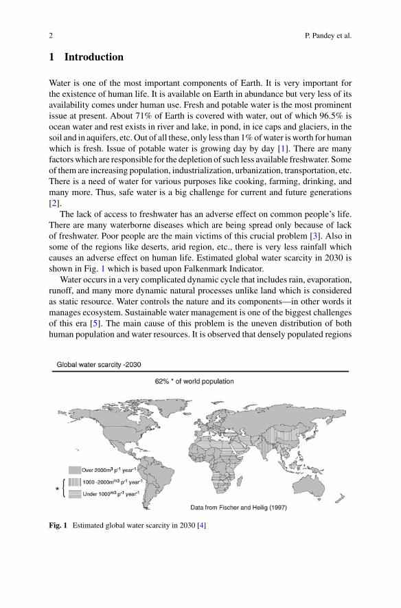
The lack of access to freshwater has an adverse effect on common people’s life.There are many waterborne diseases which are being spread only because of lackof freshwater. Poor people are the main victims of this crucial problem [3]. Also insome of the regions like deserts, arid region, etc., there is very less rainfall whichcauses an adverse effect on human life. Estimated global water scarcity in 2030 isshown in Fig. 1 which is based upon Falkenmark Indicator.
Water occurs in a very complicated dynamic cycle that includes rain, evaporation,runoff, and many more dynamic natural processes unlike land which is consideredas static resource. Water controls the nature and its components—in other words itmanages ecosystem. Sustainable water management is one of the biggest challengesof this era [5]. The main cause of this problem is the uneven distribution of bothhuman population and water resources. It is observed that densely populated regions
Fig. 1 Estimated global water scarcity in 2030 [4]
Desalination and Solar Still: Boon to Earth 3
are having less availability of water and lower populated regions are having adequateor even surplus water availability.
It is not only physical water scarcity which are creating problems to humankindbut also social water scarcity which is growing day by day. Social water scarcityis a water issue which comes into account due to political parties, policies, andsocioeconomic relationships [6].
Due to rapid population growth, freshwater need is increasing day by day. It isbecoming difficult to fulfill everyone’s freshwater need [7]. Shortage of freshwater isdamaging the ecosystem gradually which is one of the dangerous threats to mankind.Freshwater depletion is not the issue of arid regions only rather it has becomecommonthroughout the world [8]. It is very essential to keep control over the depletion offreshwater and to generate more fresh and potable water from other source of waterwhich are not useful to human beings directly.
2 Desalination: A Solution
Water shortage is one of the toughest and threatening issues of today’s generation.More than 15% of the world’s population is deprived of fresh and potable water, outof which some are living in improper sanitation and unhygienic surroundings. Toovercome this deteriorating condition, more and more water is made from seawaterwhich is available in abundance onEarth [9]. This very process can be successfulwithdesalination. Desalination is one of the simplest, earliest, best solutions to freshwatershortage.
The principle of hydrological cycle is followed in man-made desalination processusing other sources of heating and cooling. Large amount of energy is needed toseparate freshwater frombrine and salty seawater.Desalination takes place by feedingsaltwater into themethodwhich gives two output streams as a result, one is freshwaterstream and another is salt-contaminated water stream. Thus, freshwater is obtainedby desalinating saltwater [10].
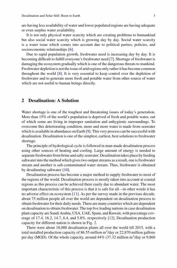
Desalination process has become a major method to supply freshwater to most ofthe regions of the world. Desalination process is mostly taken into account at coastalregions as this process can be achieved there easily due to abundant water. The mostimportant characteristic of this process is that it is safe for all—in other words it hasno adverse effect on ecosystem [11]. As per the survey made in the previous decade,about 75 million people all over the world are dependent on desalination process toobtain freshwater for their daily needs. There aremany countrieswhich are dependenton desalination to obtain freshwater. The top five leading nations in case desalinationplant capacity are SaudiArabia, USA,UAE, Spain, andKuwait, with percentage cov-erage of 17.4, 16.2, 14.7, 6.4, and 5.8%, respectively [12]. Desalination productioncapacity for different nation is shown in Fig. 2.
There were about 18,000 desalination plants all over the world till 2015, with atotal installed production capacity of 86.55 million m3/day or 22,870 million gallonsper day (MGD). Of the whole capacity, around 44% (37.32 million m3/day or 9,860
4 P. Pandey et al.
Fig. 2 Desalination production capacity with different categories for a the world, b the USA, andc other Middle East countries in 2002 [13]
MGD) is located in the Middle East and North Africa. Due to current advancementin technologies related to desalination, 80% of the energy used for water productionover 20 years has been reduced [13].
3 Methods of Desalination
Basically, there are various methods of desalinating brackish and salty seawater.Commercially and economically out of all methods, MSFD, RO, andMED are takeninto account for the desalination purpose. It has been observed that these three meth-ods are the leading ones and in the coming future these three would be the mostcompetitive [8]. There are various methods of desalination which are as under.
3.1 Multi-stage Flash Distillation (MSFD)
The basic principle of MSFD is flash evaporation. In this very process, evaporationof seawater takes place by the reduction of pressure as opposed so as to increase thetemperature. To get the maximum product and to maintain the economies of MSFD,generally regenerative heating is done. Due to regeneration, the seawater flashingin the flashing chamber provides its heat to the seawater going through the flashingmethod. As this is a regenerative heating, this process needs different stages for thecompletion. There is a need to raise the temperature of incoming seawater at eachstage gradually [14]. This gradual increase in temperature of seawater is achieved bythe heat of condensation which is released by the condensing water vapor. There arebasically three parameters essential for a MSFD plant, and these are heat input, heatrecovery, and lastly heat rejection. There are some chances of scale formation in theMSFD plant, and to remove that scale formation, some high-temperature additivesare used [15].
In modern MSFD plant, multi-stage evaporators are used in which about 19–28stages are there [16]. The operating temperature of MSFD plant is in the range of
Desalination and Solar Still: Boon to Earth 5
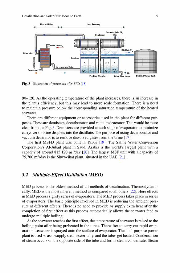
Fig. 3 Illustration of processes of MSFD [18]
90–120. As the operating temperature of the plant increases, there is an increase inthe plant’s efficiency, but this may lead to more scale formation. There is a needto maintain pressure below the corresponding saturation temperature of the heatedseawater.
There are different equipment or accessories used in the plant for different pur-poses. These are demisters, decarbonator, and vacuum deaerator. This would bemoreclear from the Fig. 3. Demisters are provided at each stage of evaporator to minimizecarryover of brine droplets into the distillate. The purpose of using decarbonator andvacuum deaerator is to remove dissolved gases from the brine [17].
The first MSFD plant was built in 1950s [19]. The Saline Water ConversionCorporation’s Al-Jubail plant in Saudi Arabia is the world’s largest plant with acapacity of around 815,120 m3/day [20]. The largest MSF unit with a capacity of75,700 m3/day is the Shuweihat plant, situated in the UAE [21].
3.2 Multiple-Effect Distillation (MED)
MED process is the oldest method of all methods of desalination. Thermodynami-cally, MED is the most inherent method as compared to all others [22]. Here effectsin MED process signify series of evaporators. TheMED process takes place in seriesof evaporators. The basic principle involved in MED is reducing the ambient pres-sure at different effects. There is no need to provide or supply extra heat after thecompletion of first effect as this process automatically allows the seawater feed toundergo multiple boiling.
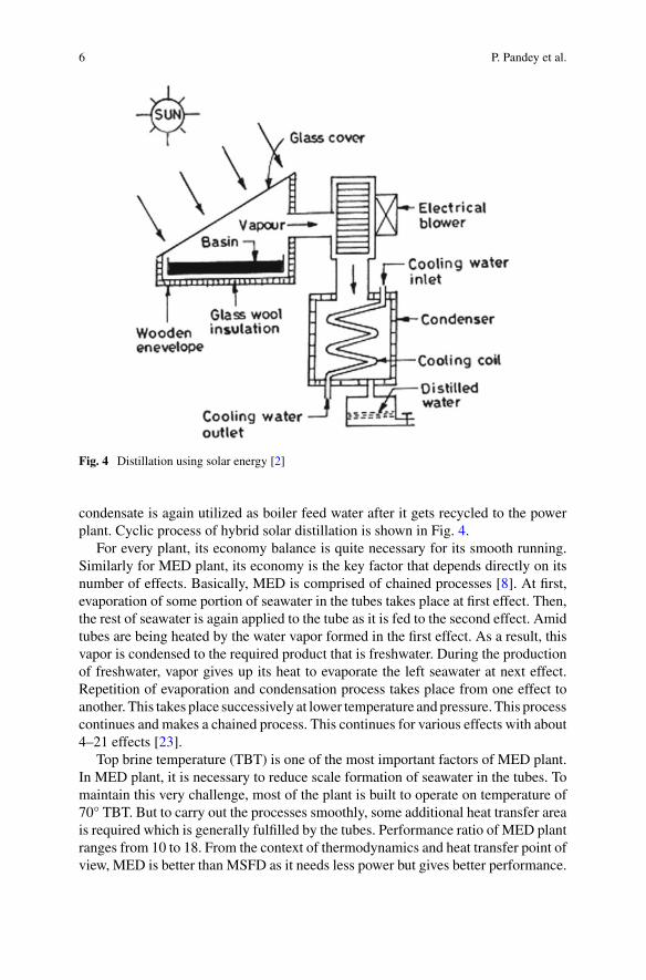
As the seawater reaches the first effect, the temperature of seawater is raised to theboiling point after being preheated in the tubes. Thereafter to carry out rapid evap-oration, seawater is sprayed onto the surface of evaporator. The dual-purpose powerplant is used so as to supply steam externally, and the tubes get heated. Condensationof steam occurs on the opposite side of the tube and forms steam condensate. Steam
6 P. Pandey et al.
Fig. 4 Distillation using solar energy [2]
condensate is again utilized as boiler feed water after it gets recycled to the powerplant. Cyclic process of hybrid solar distillation is shown in Fig. 4.
For every plant, its economy balance is quite necessary for its smooth running.Similarly for MED plant, its economy is the key factor that depends directly on itsnumber of effects. Basically, MED is comprised of chained processes [8]. At first,evaporation of some portion of seawater in the tubes takes place at first effect. Then,the rest of seawater is again applied to the tube as it is fed to the second effect. Amidtubes are being heated by the water vapor formed in the first effect. As a result, thisvapor is condensed to the required product that is freshwater. During the productionof freshwater, vapor gives up its heat to evaporate the left seawater at next effect.Repetition of evaporation and condensation process takes place from one effect toanother. This takes place successively at lower temperature and pressure. This processcontinues and makes a chained process. This continues for various effects with about4–21 effects [23].
Top brine temperature (TBT) is one of the most important factors of MED plant.In MED plant, it is necessary to reduce scale formation of seawater in the tubes. Tomaintain this very challenge, most of the plant is built to operate on temperature of70° TBT. But to carry out the processes smoothly, some additional heat transfer areais required which is generally fulfilled by the tubes. Performance ratio of MED plantranges from 10 to 18. From the context of thermodynamics and heat transfer point ofview, MED is better than MSFD as it needs less power but gives better performance.
Desalination and Solar Still: Boon to Earth 7
Horizontal MED plant is more frequent than other types of plant [24]. Moreover,these are successfully operating for 30–40 years. Various types of tubes can be usedin MED plant like vertical, horizontal, and submerged types. But most frequent ishorizontal tubes.
3.3 Vapor Compression Distillation (VCD)
In VCD, compression of vapor plays an important role in providing heat to carryout evaporation of seawater. The basic principle of VCD is reduction of boilingpoint temperature by the reduction of pressure [25]. Due to this very principle, VCDtakes advantage over other methods. Mainly, two methods are used to carry outVCD—they are steam jet andmechanical compressor. These twomethods are used tocondense water vapor so that sufficient heat can be produced to carry out evaporationof seawater. Here electrically driven method is mechanical compressor.
There exist various types of configuration of VCD units. This allows easyexchange of heat to carry out evaporation of seawater. Steam jet type of VCD isalso called thermocompressor. In thermocompressor, there is a venturi orifice at thesteam jet which creates and extracts water vapor from the evaporator, thus creates alower ambient pressure. Thereafter, steam jet compresses the water vapor extractedby the venturi orifice. Then condensation of mixture takes place on the wall of tubewhich provides thermal energy to evaporate the seawater.
The other type of VCD is low-temperature VCD which requires only power.Hence, it is very simple, efficient, and reliable process. This method is applicablefor mainly small-scale units of desalination. There are various application areas ofVCD units like resorts, drilling sites, and industries. This is very beneficial as it canbe used where there is lack of freshwater [26].
3.4 Reverse Osmosis (RO)
The basic principle involved in this process is that osmotic pressure is to be over-come. To overcome osmotic pressure, an external pressure is applied which is greaterthan that of osmotic pressure on seawater. In reverse osmosis process, flow of waterreverses the direction of natural flow across the membrane; consequently, dissolvedsalt is left behind with increased salt concentration. In this process, there is no needof phase separation and heating. Here energy is required to pressurize the seawa-ter feed to carry out the desalting process [27]. The key factors of RO plant is itsmajor components. There are four major components of RO plant, and they are feedwater pretreatment, membrane separation, high-pressure pumping, and permeatepost-treatment.
There are various undesirable components in the seawater which can damagethe membrane. Hence, there is a need to eliminate those constituents which is done
8 P. Pandey et al.
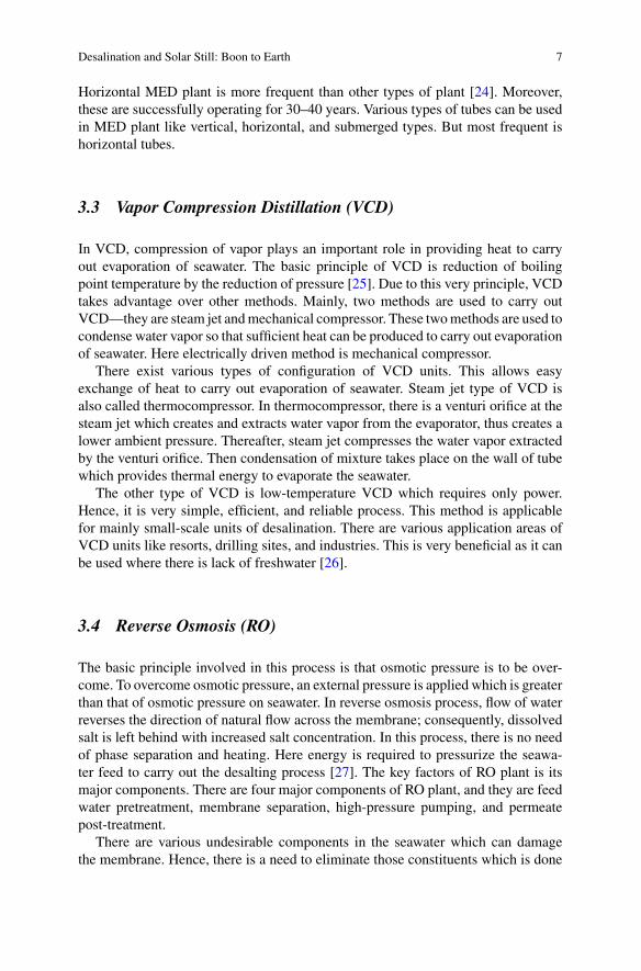
Fig. 5 Schematic ofone-stage seawater RO [13]
by pretreatment [28]. Pretreatment of water includes various methods like coagu-lation, chlorination, acid addition, multimedia filtration, micron cartridge filtration,and dechlorination. Pretreatment of seawater feed depends on different factors likemembrane type, feed water characteristics, membrane configuration, recovery ratio,and product water quality. Depending upon these factors, the type of pretreatment isselected.
The key factor of RO process is to reject salt present in the seawater, for whichpretreated feedwater pressure is to be raised to that extent so that it should be appro-priate to the RO membrane and water can easily pass through them. To raise suchpressure, high-pressure stainless steel pumps are used. Themembrane should be suchthat it can bear the entire pressure drop across it. Generally, centrifugal pumps areused to carry out this operation. An illustration of one-stage RO is shown in Fig. 5.
There are variousmembrane configurations, out ofwhich spiralwound and hollowfine fiber (HFF) are most economical and commercially successful. The shape ofHFF is like U-shaped fiber. In HFF, cellulose triacetate and polyamide are used asmembrane materials [29].
Post-treatment is one of the most important components of RO process. In posttreatmentmainly pH is adjusted, lime is added and dissolved gases like H2S andCO2.Two changes and developments which were introduced in the previous decade havereduced the operating cost of RO plant. Those two developments are: developmentof membrane to operate efficiently for longer time and energy recovery device [30].The devices are used for the purpose of converting pressure drop into rotating energy;hence, the devices are mechanical in nature.
Desalination and Solar Still: Boon to Earth 9
3.5 Freezing
Desalination of seawater can also be done by the process of freezing. It is a verysimple process to obtain freshwater from seawater. During freezing, ice crystals areformed. Due to formation of ice crystals, dissolved salts are removed. It can beachieved under controlled situation. The mixture of seawater is generally cleanedand washed for removing salt in the water left, just before the completion of freez-ing of whole water. Thus, freshwater is obtained by melting the frozen ice. Hence,desalination by freezing includes various processes like firstly seawater cooling,then partial crystallization of ice, thereafter ice is separated from seawater, then mostimportantly melting of ice to get freshwater, at last finishing processes refrigerationand heat rejection [31].
Desalination by freezing has lots of advantages. Some of them are lower powerconsumption, less corrosion, less scaling and precipitate formation. Along withadvantages, there are disadvantages too like handling water and ice mixtures. This isvery difficult to handle these twomixtures together as these aremechanically difficultto process.
Although this process has plenty of advantages, still this is not accepted commer-cially till now to produce freshwater in mass. Very few plants have been made tillnow which proves that it is not reliable. Most famous plant till now was constructedin Saudi Arabia in 1985. This very plant was an experimental solar-powered unit[32]. To govern plant status, few processes were developed like hydrate, indirect,eutectic, triple point, and secondary refrigerant processes [33].
3.6 Solar Distillation
Solar desalination is one such process of desalination in which solar energy is theprimary energy source to carry out desalination of seawater. In this process, solarenergy is used directly for desalinating seawater. Moreover, this process is similarto the process of hydrological cycle. In hydrological cycle, water vapor is producedby heating the seawater with the sun’s ray, and then, condensation of vapor takesplace which ultimately gives condensate which is further collected as product water.Greenhouse solar still is one of the examples of this type of desalination process[34].
This process was developed to increase the efficiency of solar still, but it wasseen that it requires large solar collection area approximately 25 ha land/1000 m3 ofproduct water/day [26]. Not only space but also high capital cost and vulnerabilityto weather-related damage are also its disadvantages.
10 P. Pandey et al.
3.7 Potabilization
Potabilization is also a desalinating process, but it is an additive process to MSF.In other words, it is a suffix to MSF. When MSFD completes, there are some smallamount of impurities like dissolved salts and minerals so the produced desalinatedwater is little bit corrosive to the metals used in materials for water distributionsystem. To avoid all these problems, potabilization is practiced [35].
There are mainly two typical methods which carry out potabilization process.These are: injection of carbon dioxide and hydrated lime [36], and carbonatedwater ispassed through limestone bed filters [37]. Basically, there are four processes involvedin potabilization process—carbonation, liming, chlorination, and aeration. Limingand carbonation processes signify remineralization of water by the addition of car-bon dioxide and hydrated lime. The basic objective of liming and carbonation is toincrease hardness, alkalinity, mineral content, and pH. There is a need to eliminatebacterial growth that is to disinfect water. To avoid water from infection, chlorina-tion process is carried out [38]. It is done by injecting either chlorine gas or calciumhypochlorite. Last but not least, aeration process is carried out to replace oxygen soas to improve water taste.
4 Modification and Advancement in Different Technologyof Desalination
4.1 Advancement in MSFD
MSFD is an efficient process of desalination. But there is a need for modificationand optimization in design of equipment, design based on thermodynamics, selec-tion of materials, structural aspects, techniques of construction and transportation.There has been a gradual evolution in MSFD which includes various changes inthe design, construction, instrumentation, etc. [39]. There has been a gradual evolu-tion in technologies of MSFD which includes vertical MSFD, chemical treatment,equilibration, construction materials, construction techniques, heat transfer, control,instrumentation, etc.
The concept of desalination came into account in the early 1960s. The increaseddemand for freshwater in the arid regions likeMiddle East prevailed the developmentof desalination. From then, desalination plant began in the market. At that time, asper the market demand, plant with capacity of 4500 m3/day was built.
There were various problems in the initial stages of development of desalinationplant. Mainly, design concept and economies were the two vital issues. Due to lackof concept of equilibration, discrepancy between brine and water vapor at low tem-perature increased. Due to changing and traditional technology, now plant of largesize with capacity of 75,850 m3/day is also viable like in UAE [40]. The size ofMSFD plant can be extended up to 136,260 m3/day as per the study [41].
Desalination and Solar Still: Boon to Earth 11
Thepurity of theproductwater is disturbeddue the entry of brine into vapor stream.To overcome this problem, “demisters” are installed. There is a need to care of thedesign and position of demisters in the evaporator. As the scale formation in MSFDis very less, to overcome the least amount of scale formation some chemical additiveshad been developed [42]. Various additives were introduced and rejected. Later high-temperature additives were taken into account which can allow the operation at even115°.
In the initial stage of construction ofMSFD plants, carbon steel (CS) material wasgenerally used for the mechanical parts of the plant, mainly the shell. Later its usewas omitted due to its heavy weight. Then stainless steel (SS) and duplex steel cameinto account as the major materials for mechanical components. Use of SS reducedthe weight of the mechanical components and size of the plant. Moreover, the use ofSS reduced the cost of production of water.
To improve heat and mass transfer performance of ejector system, titanium tubeswere used. Titanium tubes controlled the corrosive vapors inside the evaporatoreffectively. Later Incoloy 825 nickel was also used for making ejector as it has a veryhigh pitting resistance equivalent (PRE) number [43].
Optimization of equipment makes possible for the plant to delete major redun-dancies from the plant configuration. Due to certain changes and advancement intechnologies in MSFD plant designing fouling factors have been reduced in ther-modynamic design of MSF plants. Later on, improvement in transportation andmanufacturing has also improved. Due to improvement in manufacturing and trans-portation, completion of whole project can be achieved in a very short time. Ventingsystem has also been improved which has resulted in diminishing of concentrationof corrosive gas inside the evaporator. This very improvement has increased the lifeof evaporator equipment.
Due to all these improvements and advancements, performance of the MSFDplant has improved a lot. When plant is newly set up, its performance ratio is nearly9 and after some years it becomes 8, and 7.5 in fouled condition.
4.2 Advancement in MED
MED is one of the large-scale and cost-effective desalination plants. It consumes lesspower than that of MSFD [44]. It has significant potential to reduce cost of productwater. Its rated power consumption is below 1.8 Kwh/m3 of distillate.
Gained output ratio which is abbreviated as GOR is higher for MED as comparedto MSFD. GOR value of MSFD is 10, whereas MED has GOR value of 15. Thereare various plants with various units which have been set up and some are underconstruction. Basically, low-temperature MED plants are being made and underconstruction. In Sharjah, there are two units of MED plant with the capacity of22,700 m3/day. There exists a design and demonstration module for capacity of45,400 m3/day. The main issue of desalination plant is scaling and rate of corrosion.Design of MED with TBT of about 70° has prevented this problem [45].
12 P. Pandey et al.
There was a plan in Southern California, USA, to build a unit of capacity283,875 m3/day whose budget was approximately $30 million. The main purposeof this plant was to use vertical tube MED process. The main objective of this plantwas to reduce plant’s capital cost too.
4.3 Advancement in Reverse Osmosis
There have been a lot of changes and improvements in technology in RO process.These very advancements have helped in reducing both capital and operational costs.There are various improvements in different components of the RO plant, but most ofthe progress has beenmade in themembranes. Thus, various areaswere improved likeresistance to compression became better, durability increased, flux was improved,and salt passage was also improved and became smooth.
In 1970s and 1980s, RO came into effect as a competitor to MSFD. It has beenobserved that RO train size has increased as compared to the previous RO trains. ROtrain size has reached to 9084–13,626 m3/day some years back. But it is still smallerthan that of the size ofMSFDplantswhichwere in the rangeof 56,775–68,130m3/dayat that time. There had been a major difference in capacity of RO plant between 2005and 2008. The capacity of plant has reached to 3.5 from 2 million m3/day [46].
Presently, the recovery rate in the RO plant is nearly 35%. This recovery has beenachieved in Middle East nations where about 70% of the desalination water in theworld is produced. As per the latest report, 60% recovery rate has been reported inthe region of Pacific Ocean [47].
Recovery of energy helps RO plant to consume less energy as compared to otherplants. ROplant consumes approximately 6–8 kWh/m3 excluding recovery of energy.But including energy recovery, power consumption reduces to 4–5 KWh/m3. Cur-rently as per the survey, energy consumption has been drastically reduced to therange of 1.8–2.2 kWh/m3 due to advancement in RO technology [48].
RO method for desalination has lots of advantages, but there is a problem withRO method. The problem of pretreatment is a big deal for RO plant [49]. Previouslyfor pretreatment, filtration process was used but as per the report it is an inadequateprocess for pretreatment. Silt Density Index (SDI) is the key factor for RO plant. It isvery necessary to maintain the required filtrated SDI, but it is difficult for RO plantto maintain the required SDI which is a major disadvantage of RO plant.
To resolve this issue of pretreatment, a technology has been developed callednanofiltration (NF). NF membrane treatment proved beneficial, and excellent resultswere obtained [50]. This process increased the rate of production by40%and also pre-vented membrane fouling. There were various materials which were used to developRO membrane, and some of them are polyether amide hydrazide, polyhydroxyethylmethacrylate, etc.
Presently, membranes of low energy and high productivity are available. Manu-facturers of membrane now provide membrane of capacity 47.5 m3/day [46].
Desalination and Solar Still: Boon to Earth 13
5 Economics Related with Desalination
The economyof a plant depends primarily on production cost, location of plant,main-tenance cost, energy consumption, etc. Due to change in technologies and advance-ments in desalination, cost of production is decreasing gradually but on the otherhand due to more contamination of water because of population, pollution, etc., costof water treatment is increasing day by day due to high demand of pure water.
The key factors to select process between two major processes for desalination ofwater like RO andMSFD are technical and economic conditions. Some of the techni-cal conditions which are taken into account are energy source, energy consumption,freshwater quality, space for plant, plant reliability, operational aspects, plant size,etc. Economic conditions are taken into account based on capital, labor, materials,chemicals, etc. [51].
For a desalination plant, a cogeneration scheme is necessary in conjunction withthe generation of power for the best economy of the plant. Economics of desalina-tion plant is determined by the life cycle cost analysis. To evaluate annual plant cost,O&M, that is operation and maintenance costs, are converted into annual cost. Thecost of production of water is evaluated by dividing the sum of all costs by total quan-tity of water. There are various parameters which affect the life cycle cost analysislike plant life, direct capital cost, indirect capital cost, and capacity of production.This cost of production of freshwater is estimated in $/m3. For example, the world’slargest RO plant has water production cost of $0.53/m3 [52].
6 Future Expectance
In last two decades, there have been various improvements in desalination of brackishand brine water. Many new technology and advancements have been introduced toincrease the production of water from desalination. Economic condition has alsoimproved due to reduction in water production costs. It has been accepted withadvancement in technology mainly in arid regions of the world [8]. To minimize costof production of water from desalination, further R&D has been taken into account.There is a need to emphasize R&D in technological advancements to improve theplant’s economy. There are various parts and factors linked to desalination whereR&D efforts are made and some of them are [53]: cogeneration system of desalinatedwater and power, energy utilization mainly solar energy and nuclear energy, thermaldistillation process at very high temperature, technical aspects of differentmethods ofdesalination, chemical therapy for seawater feed, economy of different desalinationprocesses, perfect choice of construction and manufacturing materials, promotion oflarge-scale plants, scale-controlling system, cost-effective materials, introduction ofhybrid systems like NF-RO, MSF-RO, etc., environmentally friendly desalination,sent percent separation of seawater and freshwater.
14 P. Pandey et al.
7 Solar Still
Water is the most important component of our planet. It covers about 75% of theEarth, but still out of that much abundant water only 1% can be used as domesticpurpose, perhaps which are being contaminated by various factors like pollution,sewage disposal, etc. There is a need to obtain freshwater, and most of the waterpresent on the Earth is brackish and salty. Desalination is one of the measures toget freshwater from brackish water. To utilize desalination as an important measure,solar still is being introduced in this developing world. Solar still is a device which iscompletely based on the principle of desalination. It mainly uses the concept of solardistillation. It is now being used worldwide mainly in coastal areas where seawateris available in abundance. It is simple, cost-effective, and easily maintained process[54]. The main disadvantage of solar still is that it has less productivity. Variousresearches and developments are going on so as to enhance the efficiency of solarstill.
For the development and modification of solar still, various researches are goingon the basic design of solar still to increase its productivity and make it more cost-effective [55]. Themain idea for increasing the productivity of solar still is by increas-ing heat transfer rate. To implement this very idea, many researchers have used fins[56].
Srithar andMani are very famous scientists who have worked a lot on the develop-ment of solar still. Both of them dealt with the evaporation rate of industrial effluents.They developed a pilot plant for augmenting the evaporation rate. They developedpilot plant in two stages, onewith spray network systems and another with open fiber-reinforced plastic flat plate collector. Then, they both analyzed the performances ofthem separately and compared to select the better one [57]. Sometimes, performancewas judged by means of usage of sponges.
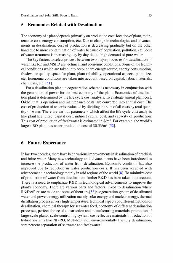
There are various components of solar still like glass cover, container, basin liner,and trough. In solar still, black paint is used to coat inside surface of container; then,collector is combined connected to glass cover. Saline and brackish water is filledinto the container under purification. Glass cover helps the radiation from the sunto be transmitted and later would be absorbed by the basin which further heats theimpure water. Thereafter, condensation of evaporated water takes place below theglass surface. Thus, it gathers in a trough which is located along the length. Simplebasin solar still is shown in Fig. 6 [1].
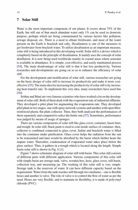
Figure 7 shows schematic diagram of solar still with basin. This solar still consistsof different parts with different application. Various components of this solar stillwith simple basin are storage tank, valve, wooden box, hose, glass cover, still basin,collection tray, and measuring jar. The working of this solar still is very simple.Storage tank is the reservoir of water. It can have different capacity based on therequirement. Water from the tank reaches still through twomediums—one is flexiblehoses and another is valve. The role of valve is to control the flow of water as per theneed. Hoses are very flexible, and to maintain its flexibility, it is made of polyvinylchloride (PVC).
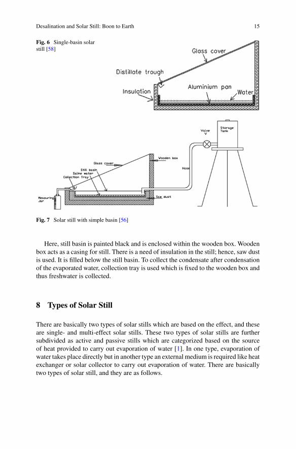
Desalination and Solar Still: Boon to Earth 15
Fig. 6 Single-basin solarstill [58]
Fig. 7 Solar still with simple basin [56]
Here, still basin is painted black and is enclosed within the wooden box. Woodenbox acts as a casing for still. There is a need of insulation in the still; hence, saw dustis used. It is filled below the still basin. To collect the condensate after condensationof the evaporated water, collection tray is used which is fixed to the wooden box andthus freshwater is collected.
8 Types of Solar Still
There are basically two types of solar stills which are based on the effect, and theseare single- and multi-effect solar stills. These two types of solar stills are furthersubdivided as active and passive stills which are categorized based on the sourceof heat provided to carry out evaporation of water [1]. In one type, evaporation ofwater takes place directly but in another type an external medium is required like heatexchanger or solar collector to carry out evaporation of water. There are basicallytwo types of solar still, and they are as follows.
16 P. Pandey et al.
8.1 Single-Effect Solar Still
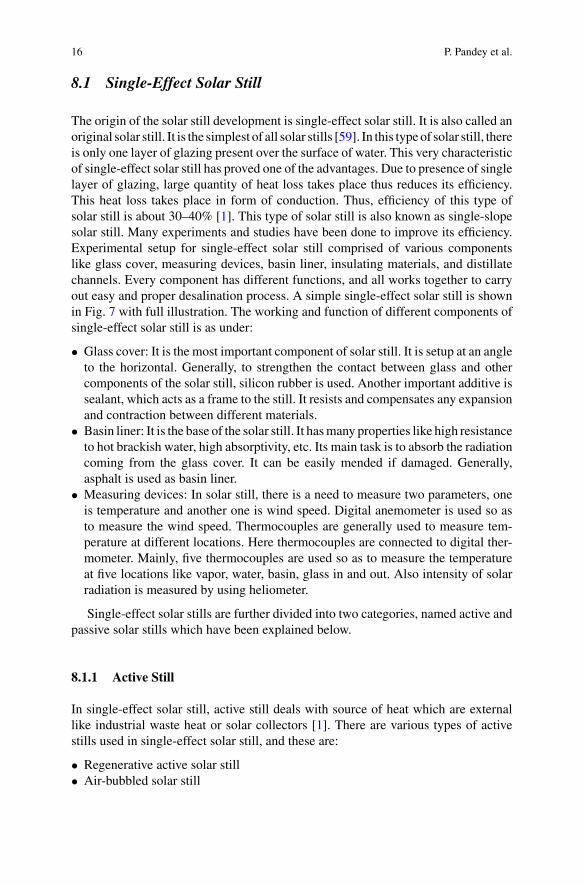
The origin of the solar still development is single-effect solar still. It is also called anoriginal solar still. It is the simplest of all solar stills [59]. In this typeof solar still, thereis only one layer of glazing present over the surface of water. This very characteristicof single-effect solar still has proved one of the advantages. Due to presence of singlelayer of glazing, large quantity of heat loss takes place thus reduces its efficiency.This heat loss takes place in form of conduction. Thus, efficiency of this type ofsolar still is about 30–40% [1]. This type of solar still is also known as single-slopesolar still. Many experiments and studies have been done to improve its efficiency.Experimental setup for single-effect solar still comprised of various componentslike glass cover, measuring devices, basin liner, insulating materials, and distillatechannels. Every component has different functions, and all works together to carryout easy and proper desalination process. A simple single-effect solar still is shownin Fig. 7 with full illustration. The working and function of different components ofsingle-effect solar still is as under:
• Glass cover: It is the most important component of solar still. It is setup at an angleto the horizontal. Generally, to strengthen the contact between glass and othercomponents of the solar still, silicon rubber is used. Another important additive issealant, which acts as a frame to the still. It resists and compensates any expansionand contraction between different materials.
• Basin liner: It is the base of the solar still. It hasmany properties like high resistanceto hot brackish water, high absorptivity, etc. Its main task is to absorb the radiationcoming from the glass cover. It can be easily mended if damaged. Generally,asphalt is used as basin liner.
• Measuring devices: In solar still, there is a need to measure two parameters, oneis temperature and another one is wind speed. Digital anemometer is used so asto measure the wind speed. Thermocouples are generally used to measure tem-perature at different locations. Here thermocouples are connected to digital ther-mometer. Mainly, five thermocouples are used so as to measure the temperatureat five locations like vapor, water, basin, glass in and out. Also intensity of solarradiation is measured by using heliometer.
Single-effect solar stills are further divided into two categories, named active andpassive solar stills which have been explained below.
8.1.1 Active Still
In single-effect solar still, active still deals with source of heat which are externallike industrial waste heat or solar collectors [1]. There are various types of activestills used in single-effect solar still, and these are:
• Regenerative active solar still• Air-bubbled solar still
Desalination and Solar Still: Boon to Earth 17
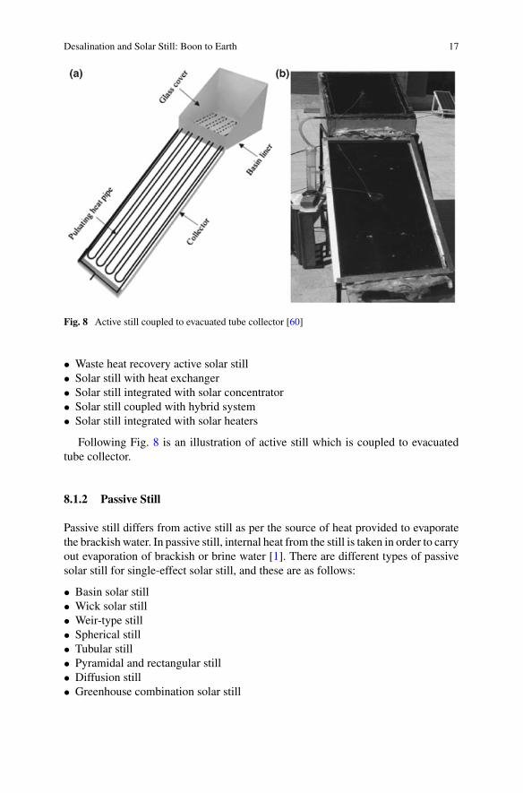
Fig. 8 Active still coupled to evacuated tube collector [60]
• Waste heat recovery active solar still• Solar still with heat exchanger• Solar still integrated with solar concentrator• Solar still coupled with hybrid system• Solar still integrated with solar heaters
Following Fig. 8 is an illustration of active still which is coupled to evacuatedtube collector.
8.1.2 Passive Still
Passive still differs from active still as per the source of heat provided to evaporatethe brackish water. In passive still, internal heat from the still is taken in order to carryout evaporation of brackish or brine water [1]. There are different types of passivesolar still for single-effect solar still, and these are as follows:
• Basin solar still• Wick solar still• Weir-type still• Spherical still• Tubular still• Pyramidal and rectangular still• Diffusion still• Greenhouse combination solar still
18 P. Pandey et al.
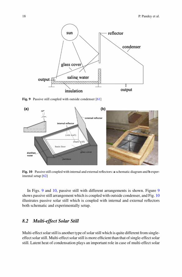
Fig. 9 Passive still coupled with outside condenser [61]
Fig. 10 Passive still coupledwith internal and external reflectors: a schematic diagram and b exper-imental setup [62]
In Figs. 9 and 10, passive still with different arrangements is shown. Figure 9shows passive still arrangement which is coupled with outside condenser, and Fig. 10illustrates passive solar still which is coupled with internal and external reflectorsboth schematic and experimentally setup.
8.2 Multi-effect Solar Still
Multi-effect solar still is another type of solar still which is quite different from single-effect solar still.Multi-effect solar still ismore efficient than that of single-effect solarstill. Latent heat of condensation plays an important role in case of multi-effect solar
Desalination and Solar Still: Boon to Earth 19
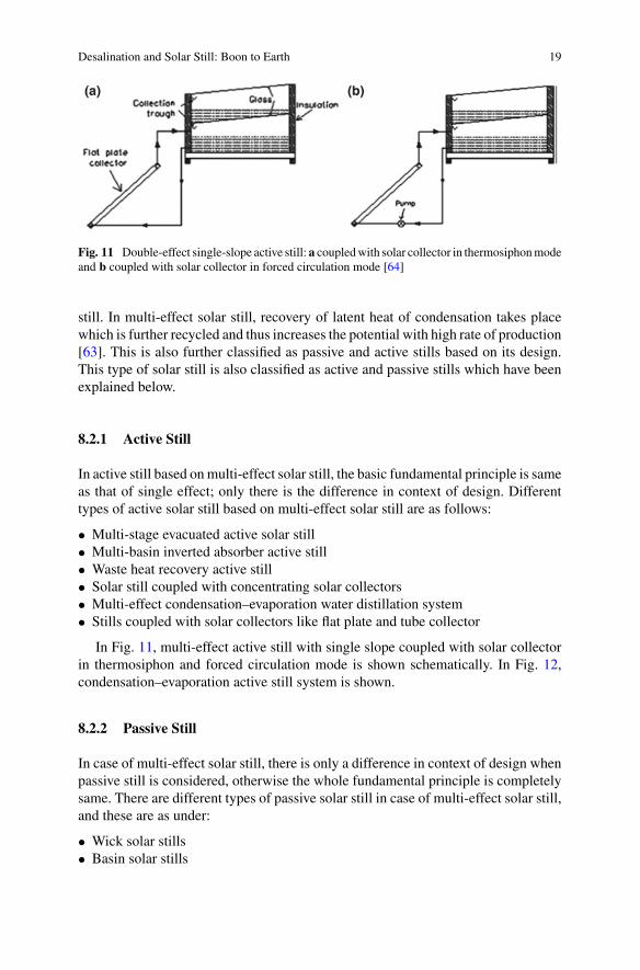
Fig. 11 Double-effect single-slope active still: a coupledwith solar collector in thermosiphonmodeand b coupled with solar collector in forced circulation mode [64]
still. In multi-effect solar still, recovery of latent heat of condensation takes placewhich is further recycled and thus increases the potential with high rate of production[63]. This is also further classified as passive and active stills based on its design.This type of solar still is also classified as active and passive stills which have beenexplained below.
8.2.1 Active Still
In active still based onmulti-effect solar still, the basic fundamental principle is sameas that of single effect; only there is the difference in context of design. Differenttypes of active solar still based on multi-effect solar still are as follows:
• Multi-stage evacuated active solar still• Multi-basin inverted absorber active still• Waste heat recovery active still• Solar still coupled with concentrating solar collectors• Multi-effect condensation–evaporation water distillation system• Stills coupled with solar collectors like flat plate and tube collector
In Fig. 11, multi-effect active still with single slope coupled with solar collectorin thermosiphon and forced circulation mode is shown schematically. In Fig. 12,condensation–evaporation active still system is shown.
8.2.2 Passive Still
In case of multi-effect solar still, there is only a difference in context of design whenpassive still is considered, otherwise the whole fundamental principle is completelysame. There are different types of passive solar still in case of multi-effect solar still,and these are as under:
• Wick solar stills• Basin solar stills
20 P. Pandey et al.
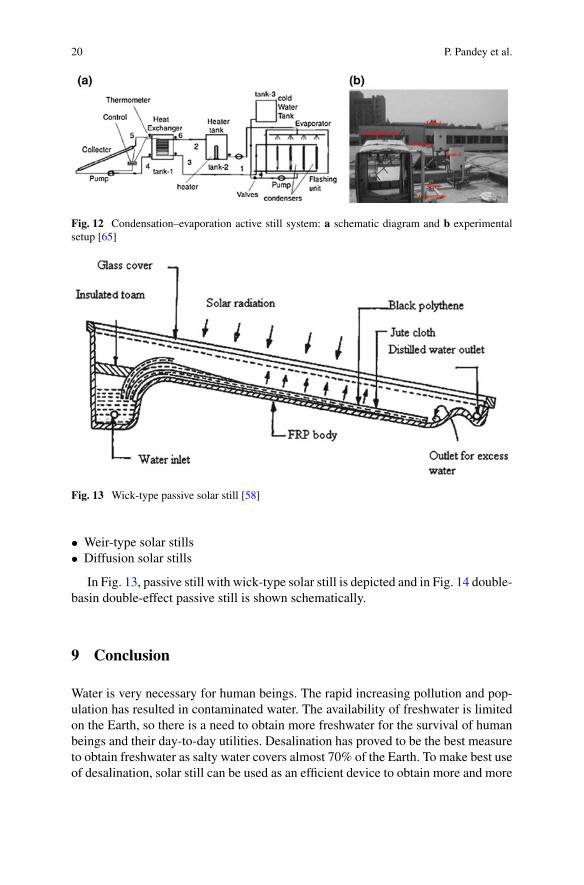
Fig. 12 Condensation–evaporation active still system: a schematic diagram and b experimentalsetup [65]
Fig. 13 Wick-type passive solar still [58]
• Weir-type solar stills• Diffusion solar stills
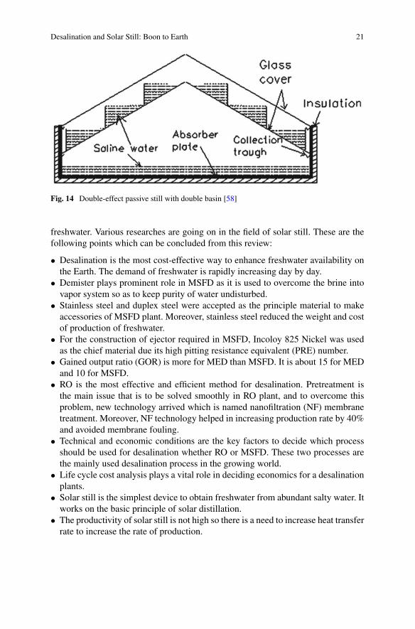
In Fig. 13, passive still with wick-type solar still is depicted and in Fig. 14 double-basin double-effect passive still is shown schematically.
9 Conclusion
Water is very necessary for human beings. The rapid increasing pollution and pop-ulation has resulted in contaminated water. The availability of freshwater is limitedon the Earth, so there is a need to obtain more freshwater for the survival of humanbeings and their day-to-day utilities. Desalination has proved to be the best measureto obtain freshwater as salty water covers almost 70% of the Earth. To make best useof desalination, solar still can be used as an efficient device to obtain more and more
Desalination and Solar Still: Boon to Earth 21
Fig. 14 Double-effect passive still with double basin [58]
freshwater. Various researches are going on in the field of solar still. These are thefollowing points which can be concluded from this review:
• Desalination is the most cost-effective way to enhance freshwater availability onthe Earth. The demand of freshwater is rapidly increasing day by day.
• Demister plays prominent role in MSFD as it is used to overcome the brine intovapor system so as to keep purity of water undisturbed.
• Stainless steel and duplex steel were accepted as the principle material to makeaccessories of MSFD plant. Moreover, stainless steel reduced the weight and costof production of freshwater.
• For the construction of ejector required in MSFD, Incoloy 825 Nickel was usedas the chief material due its high pitting resistance equivalent (PRE) number.
• Gained output ratio (GOR) is more for MED than MSFD. It is about 15 for MEDand 10 for MSFD.
• RO is the most effective and efficient method for desalination. Pretreatment isthe main issue that is to be solved smoothly in RO plant, and to overcome thisproblem, new technology arrived which is named nanofiltration (NF) membranetreatment. Moreover, NF technology helped in increasing production rate by 40%and avoided membrane fouling.
• Technical and economic conditions are the key factors to decide which processshould be used for desalination whether RO or MSFD. These two processes arethe mainly used desalination process in the growing world.
• Life cycle cost analysis plays a vital role in deciding economics for a desalinationplants.
• Solar still is the simplest device to obtain freshwater from abundant salty water. Itworks on the basic principle of solar distillation.
• The productivity of solar still is not high so there is a need to increase heat transferrate to increase the rate of production.
22 P. Pandey et al.
• Previously, single-plate solar stills were introduced in the market but later on aftervarious researches and changes, multi-effect solar still arrived in the market withmore efficiency and rate of production.
• Solar still is mainly categorized as active and passive stills. This classificationis based on the source of heat provided so as to carry out evaporation process.Active still takes heat from the external sources like industrial waste or by usingsolar collectors whether passive still takes heat internally from the still to carryout evaporation of water.
• The configuration of solar still is very simple. It is very cost-effective device toobtain freshwater from brackish and brine water. It has been proved very benefi-cial for arid and semiarid regions where there is more shortage of freshwater ascompared to other regions of the world. Various researches are going on so as toincrease its efficiency and introduce it as a large-scale production device.
References
1. Vishwanath Kumar P, Kumar A, Prakash O, Kaviti AK (2015) Solar stills system design: areview. Renew Sustain Energy Rev 51:153–181
2. Tiwari GN, Singh HN, Tripathi R (2003) Present status of solar distillation. Sol Energy75(5):367–373
3. Rijsberman FR (2006) Water scarcity: fact or fiction?. In: Agricultural water management, vol80, no 1–3 SPEC. ISS, pp 5–22
4. Wallace J (2000) Increasing agricultural water use efficiency to meet future food production.Agric Ecosyst Environ 82(1–3):105–119
5. Pahl-Wostl C (2006) Transitions towards adaptive management of water facing climate andglobal change. Water Resour Manage 21(1):49–62
6. KummuM,Ward PJ, DeMoel H, Varis O (2010) Is physical water scarcity a new phenomenon?Global assessment of water shortage over the last two millennia. Environ Res Lett 5(3)
7. McCutcheon JR,McGinnis RL, ElimelechM (2005) A novel ammonia-carbon dioxide forward(direct) osmosis desalination process. Desalination 174(1):1–11
8. KhawajiAD,Kutubkhanah IK,Wie JM (2008)Advances in seawater desalination technologies.Desalination 221(1–3):47–69
9. Saito K, IrieM, Zaitsu S, Sakai H, Hayashi H, Tanioka A (2012) Power generation with salinitygradient by pressure retarded osmosis using concentrated brine from SWRO system and treatedsewage as pure water. Desalin Water Treat 41(1–3):114–121
10. Qiblawey HM, Banat F (2008) Solar thermal desalination technologies. Desalination220(1–3):633–644
11. Lattemann S, Höpner T (2008) Environmental impact and impact assessment of seawaterdesalination. Desalination 220(1–3):1–15
12. Templer KJ, Tay C, Chandrasekar NA (2006) Motivational cultural intelligence, realistic jobpreview, realistic living conditions preview, and cross-cultural adjustment. Group Org Manage31(1):154–173
13. Greenlee LF, Lawler DF, Freeman BD, Marrot B, Moulin P (2009) Reverse osmosis desalina-tion: water sources, technology, and today’s challenges. Water Res 43(9):2317–2348
14. Kamaluddin BA, Khan S, Ahmed BM (1993) Selection of optimally matched cogenerationplants. Desalination 93(1–3):311–321
15. Consonni S, Lozza G, Macchi E (1989) Optimization of cogeneration systems operation. PartA. Prime movers modelization. In: American society of mechanical engineers, internationalgas turbine institute (publication) IGTI, vol 4, pp 313–322
Desalination and Solar Still: Boon to Earth 23
16. Sommariva C, Syambabu VSN (2001) Increase in water production in UAE. Desalination138(1–3):173–179
17. Finan MA, Harris A, Smith S (1977) The field assessment of a high temperature scale controladditive and its effect on plant corrosion. Desalination 20(1–3):193–201
18. Baig H, Antar MA, Zubair SM (2011) Performance evaluation of a once-through multi-stage flash distillation system: impact of brine heater fouling. Energy Convers Manage52(2):1414–1425
19. Younos T (2009) Environmental issues of desalination. J Contemp Water Res Educ132(1):11–18
20. Al Mudaiheem AM, Miyamura H (1985) Construction and commissioning of al jobail phaseII desalination plant. Desalination 55:1–11
21. Pankratz T (2017) Water desalination report. Water Desalination Rep 53(13):1–422. Al-Shammiri M, Safar M (1999) Multi-effect distillation plants: state of the art. Desalination
126(1–3):45–5923. Michels T (1993) Recent achievements of low temperature multiple effect desalination in the
western areas of Abu Dhabi. UAE. Desalination 93(1–3):111–11824. Ioannidis JPA (2005) Why most published research findings are false. PLoS Med
2(8):0696–070125. N. R. C. Committee on Advancing Desalination Technology (2008) Environmental issues. In:
Desalination: a national perspective, pp 108–14626. Buros OK (2000) The ABCs of desalting. Int Desalin Assoc Mass 2:1–3227. Baig MB, Al Kutbi AA (1998) Design features of a 20 migd SWRO desalination plant, Al
Jubail, Saudi Arabia. Desalination 118(1–3):5–1228. Al-Sheikh AHH (1997) Seawater reverse osmosis pretreatment with an emphasis on the Jeddah
Plant operation experience. Desalination 110(1–2):183–19229. Whitesides GM (2004) Whitesides’ Group: writing a paper. Adv Mater 16(15) SPEC.
ISS:1375–137730. Avlonitis SA,KouroumbasK,VlachakisN (2003) Energy consumption andmembrane replace-
ment cost for seawater RO desalination plants. Desalination 157(1–3):151–15831. BurosOK (1976) Conjunctive use of desalination andwastewater reclamation inwater resource
planning. Desalination 19(1–3):587–59432. Hanahan D, Weinberg RA (2011) Hallmarks of cancer: the next generation. Cell
144(5):646–67433. Manuscript A (2012) NIH public access. Changes 29(6):997–100334. Chang F et al (2006) Bigtable: a distributed storage system for structured data. In: 7th sym-
posium on operating systems design and implementation (OSDI ’06), Nov 6–8, Seattle, WA,USA, pp 205–218
35. Withers A (2005) Options for recarbonation, remineralisation and disinfection for desalinationplants. Desalination 179(1–3) SPEC. ISS:11–24
36. Khawaji AD,Wie JM (1994) Potabilization of desalinatedwater atMadinatYanbuAl-Sinaiyah.Desalination 98(1–3):135–146
37. Al-Rqobah HE, Al-Munayyis AHE (1989) A recarbonation process for treatment of distilledwater produced by MSF plants in Kuwait. Desalination 73(C):295–312
38. Ayyash Y, Imai H, Yamada T, Fukuda T, Yanaga Y, Taniyama T (1994) Performance of reverseosmosis membrane in Jeddah Phase I plant. Desalination 96(1–3):215–224
39. Morris RM (1993) The development of the multi-stage flash distillation process: a designer’sviewpoint. Desalination 93(1–3):57–68
40. Sommariva C, Borsani R, Tasca A (1991) Distillate purity from MSF: the theoretical designand a real case behaviour. Desalination 81(1–3):309–320
41. Hanbury WT (1993) Some thoughts on the limitations on increasing the unit sizes of conven-tional cross-tube MSF distillation plants. Desalination 93(1–3):127–145
42. El-Saie MHA (1993) The MSF desalination process and its prospects for the future. Desalina-tion 93(1–3):43–56
24 P. Pandey et al.
43. Khawaji AD, Wie JM (2001) Performance of MSF desalination plant components over fifteenyears at Madinat Yanbu Al-Sinaiyah. Desalination 134(1–3):231–239
44. Herlyn ELA, Radermacher FJ (2014) Sustainability: challenges for the future. In: Sustainableentrepreneurship: business success through sustainability
45. Ophir A, Gendel A (1994) Adaptation of the multi-effect distillation (MED) processto yield high purity distillate for utilities, refineries and chemical industry. Desalination98(1–3):383–390
46. Peñate B, García-Rodríguez L (2012) Current trends and future prospects in the design ofseawater reverse osmosis desalination technology. Desalination 284:1–8
47. KuriharaM, Yamamura H, Nakanishi T, Jinno S (2001) Operation and reliability of every high-recovery seawater desalination technologies by brine conversion two-stage RO desalinationsystem. Desalination 138(1–3):191–199
48. Peñate B, de la Fuente JA, Barreto M (2010) Operation of the RO Kinetic®energy recoverysystem: description and real experiences. Desalination 252(1–3):179–185
49. Rovel JM (2004) Why A SWRO In Taweelah- pilot plant results demonstrating feasibility andperformance of SWRO on gulf water. Int Desalin Water Reuse Q 13(4):24
50. Hassan AM, Farooque AM, Jamaluddin ATM, Al-Amoudi AS, Al-Sofi MAK, Al-RubaianAF, Kither NM, Al-Tisan IAR, Rowaili A (2000) A demonstration plant based on the newNF—SWRO process. Desalination 131(1–3):157–171
51. Wade NM (1993) Technical and economic evaluation of distillation and reverse osmosis desali-nation processes. Desalination 93(1–3):343–363
52. Henthorne L (2009) The current state of desalination. Int Desalin Assoc 1–253. Yin XA, Yang ZF (2011) Development of a coupled reservoir operation and water diversion
model: balancing human and environmental flow requirements. Ecol Model 222(2):224–23154. Nafey AS, Abdelkader M, Abdelmotalip A, Mabrouk AA (2001) Solar still productivity
enhancement. Energy Convers Manage 42(11):1401–140855. Al-Hayeka I, Badran OO (2004) The effect of using different designs of solar stills on water
distillation. Desalination 169(2):121–12756. Velmurugan V, Gopalakrishnan M, Raghu R, Srithar K (2008) Single basin solar still with fin
for enhancing productivity. Energy Convers Manage 49(10):2602–260857. Srithar K, Mani A (2007) Open fibre reinforced plastic (FRP) flat plate collector (FPC) and
spray network systems for augmenting the evaporation rate of tannery effluent (soak liquor).Sol Energy 81(12):1492–1500
58. RajaseenivasanT,MurugavelKK,ElangoT,HansenRS (2013)A reviewof differentmethods toenhance the productivity of the multi-effect solar still. Renew Sustain Energy Rev 17:248–259
59. Badran OO (2007) Experimental study of the enhancement parameters on a single slope solarstill productivity. Desalination 209(1–3) SPEC. ISS:136–143
60. Kargar Sharif Abad H, Ghiasi M, Jahangiri Mamouri S, Shafii MB (2013) A novel integratedsolar desalination system with a pulsating heat pipe. Desalination 311:206–210
61. El-Bahi A, Inan D (1999) A solar still with minimum inclination, coupled to an outside con-denser. Desalination 123(1):79–83
62. Tanaka H (2009) Experimental study of a basin type solar still with internal and externalreflectors in winter. Desalination 249(1):130–134
63. Tanaka H, Nosoko T, Nagata T (2002) Experimental study of basin-type, multiple-effect,diffusion-coupled solar still. Desalination 150(2):131–144
64. YadavYP (1989) Transient analysis of double-basin solar still integrated with collector. Desali-nation 71(2):151–164
65. Abdel Dayem AM (2006) Experimental and numerical performance of a multi-effectcondensation-evaporation solar water distillation system. Energy 31(14):2374–2391
Feasible Solar Applications for BrinesDisposal in Desalination Plants
Shiva Gorjian, Farid Jalili Jamshidian and Behnam Hosseinqolilou
Abstract Water is a crucial ingredient for human health and one of the very fewvital needs of human beings. More than 1.2 billion people around the work suf-fer from a deficiency of safe drinking water so that it is estimated that 14% of theglobal population lives in water-scarce regions by 2050. Although desalination hasbeen used as conventional water providing technology for a long time in the MiddleEast and the Mediterranean, it has extensive capacities in the USA, Europe, andAustralia as well. Interest in investment in desalination sector has been extendingbeyond these regions of the world which are driven by water stress concerns. Eventhough desalination has the potential to increase the water supply in water-scarceregions, its associated adverse consequences and constraints cannot be ignored. Brinedisposal is the primary environmental consequence that should be considered andstudied when installing a desalination plant. Therefore, essential steps must be takento ensure safe and sustainable brine disposal. Implementation of a proper brine dis-posal method incorporated with a qualified design and construction procedure canmitigate the destructive effects of the desalination plants on the water environmentsand groundwater aquifers. Using solar power as a renewable source can both imi-tate the environmental impacts of the conventional brine disposal methods and anincrease in the evaporation rate of the solar traditional evaporation ponds. Directingthe brine effluent into the solar saltworks can possibly produce salt, and therefore,the desalination plant would be zero liquid discharge (ZLD). This method requireslarge land areas and thus is only applicable in arid and semi-arid regions where theevaporation rates are high and the value of the land is low. Also, expensive liners areneeded to avert salt seepage from the soil and the groundwater contamination. If theevaporation rate is improved, the need for the same amount of land would conse-quently be reduced. Enhancing the rate of evaporation would have two benefits of theflexibility to increase the amount of the brine wastewater flows out of an evaporation
S. Gorjian (B) · B. HosseinqolilouBiosystems Engineering Department, Faculty of Agriculture, Tarbiat Modares University(T.M.U.), Tehran 14115-111, Irane-mail: [email protected]
F. J. JamshidianWater Resources Management and Engineering, Faculty of Civil & Environmental Engineering,Tarbiat Modares University (T.M.U.), Tehran 14115-143, Iran
© Springer Nature Singapore Pte Ltd. 2019A. Kumar and O. Prakash (eds.), Solar Desalination Technology,Green Energy and Technology, https://doi.org/10.1007/978-981-13-6887-5_2
25
26 S. Gorjian et al.
pond and a reduced amount of land that would be needed to achieve the same rateof evaporation.
Keywords Brine disposal · Solar energy · Environmental impacts · Solarsaltworks · Evaporation enhancement
1 Introduction
People need to use water to protect their lives and health. Therefore, the qualityof consumed water has immense importance to humans [1, 2]. Low water qualitycauses many diseases in humans, and however, if fresh and hygienic water is used,it can prevent the occurrence of such conditions [3–7]. The earth contains about1.4 × 109 km3 of water covering almost 70% of the planet surface where 97.5%of which is saline water. Only 2.5% of water on the earth is freshwater and 80%of which is tucked away in ice caps or trapped as soil moisture where they are notreadily available to people. About 0.5% of the freshwater on the earth is availableand should support the lives of people on the planet. Unfortunately, such a slightamount is not distributed equally throughout the world and is not available to peopleat any time and place, if needed [8, 9].
The primary sources of drinking water which is needed for domestic life, agri-culture, and industry are rivers, lakes, underground waters, seawaters, atmosphericwater, and fog collection, which are not possible to use because of their high amountof salt and harmful substances [10, 11]. The rapid growth of population and expan-sion of industry has increased the demand for drinking water in the world [7, 12,13]. Globally, around 780 million people do not have access to safe water, 1.1 bil-lion people do not have the required facilities to make the drinking water better, and2.6 billion are under improvement [14, 15]. Global dryness and desertification areexpected to deteriorate water problems around the world. Even countries that are notcurrently faced with a scarcity of water may have to deal with it in the future. It isanticipated that by 2030, the demand for water consumption in the whole world willbe about 40% higher than freshwater sources, which is indicative of the intensityof use [16, 17]. National water scarcity is known by an index that shows per capitarenewable water per year. When the water reserve of a country or a region is lowerthan 1700 m3 per capita per year, it is under normal stress. Along with that, if therenewable water supply is beneath 1000 m3 per capita per year, the area is underpersistent water stress, and it is under absolute water stress when the water supplyis lower than 500 m3 per capita per year [18]. Water scarcity not only adverselyaffects human lives on the earth, but also it prevents economic development andsocial progress [13, 19, 20]. Therefore, humans, and in particular practitioners in thewater field, should seek to create new and renewable water sources, and desalinationof seawater is one of these solutions [13, 16, 19, 21].
Feasible Solar Applications for Brines Disposal in Desalination … 27
2 Desalination and Water Security
Definition of water security is reliable access to constant volume andwater quality, asfar as it provides health, property, andproduction to the living creatures and eliminatesthe dangers of water scarcity. Sustainable development in any area is not possiblewithoutwater [22–24]. Ensuring adequate amounts of clean and safewater to detoxifyhumanand ecosystemneeds is one of themost significant challenges encountering theworld; the demand for freshwater increaseswhilemany regions around theworld facewith the reduction in water due to climate changing patterns [24]. Communities musttake all necessary measures to protect the environment by maintaining all possiblewater resources [23]. For this reason, human beings need to seek the supply of waterthrough the recycling of all impure water [22, 25]. Seawater conversion to freshwaternot only meets the needs of the community but also prevents the destructive effectof climate change on existing water reservoirs [26]. The analysis of DesalinationNational Research Council shows desalting is a realistic option for the future watersupply; therefore, nationalwater policies should include the use of seawater resourcesfor expansion of water resources in countries [23, 27]. Desalination is a procedureduring which salt and other minerals of saltwater are removed, and freshwater isproduced for various consumptions and applications [28]. Desalination is a processwhich removes salt andminerals from seawater and provides cleanwater for multipleuses [23, 28, 29]. Fortunately, desalination has become widespread throughout theworld to protect water resources, and capacity of global desalination has increasedover the past 40 years [27]. Based on the International Desalination Association(IDA), over 18,400 desalination plants are operating with the production of 86 mcm(million m3 of water) per day [30–32]. Considering the benefits of desalination,researchers still believe that it is useful only when all solutions are addressed andinformed. The community should be notified that desalination systems are easy touse, and currently, using them is the only available solution to deal with the watershortage crisis around the world [33–43].
3 Environmental Impacts of Desalination
Environmental impacts caused by desalination plants are the most serious issuesthat would be exerted by their application. Although much development progresshas happened in desalination industry, there are still concerns about the environ-mental impacts, including dissipating aquatic organisms and their natural habitats,decreasing the dissolved oxygen (DO) concentration, and the rising in water temper-ature, turbidity, and salinity as the consequences of the brine discharge. Therefore,an acceptable desalination plant should meet the environmental regulations [23, 32,44–47]. The other adverse influences can also be produced by noise, intensive energyuse followed by an increase in greenhouse gas (GHG) emissions, chemical materi-als of antiscalants, antifoulants, corrosion inhibitors, defoamers, chlorine, and acids
28 S. Gorjian et al.
which are used as the additives and reaction products which increase the level of met-als [25, 32]. Among these problems, many considerations have been attracted to thedisposal of the concentrated brine, whose improper treatment would definitely causedisturbances to the marine habitat and environmentally sensitive regions. Dischargedconcentrates have high levels of salinity and may hold low chemicals concentrationsand elevated temperatures [32, 38, 44]. Most of the desalination plants installedaround the world are using fossil fuels as the power source which is not sustainableanymore because of depletion threats of the accessible energy resources and increasesin GHG emissions [30, 48, 49]. Research and development efforts should considerthat desalination plants are energy intensive, and developing new technologies canreduce the costs and improve energy efficiency. As a scientific rule, with increasingthe demand for freshwater, there would be significant market potential for renewableenergy systems to drive desalination plants [48, 50, 51].
3.1 Environmental Impact Assessment (EIA)
Environmental impact assessment (EAI) of desalination processes is critical. This iswhile that currently, a standardEIA approach to assess andminimize the environmen-tal impacts of the desalination projects do not exist [51]. The negative consequencesof the desalination facilities can be mitigated by doing an environmental impactassessment (EIA) and implementing environmental management plans (EMPs) tomake the desalination technology sustainable [46]. The EIA reports discuss that dueto the destructive consequences that the facility has on the environment, the energysupply, social benefits and political implication, and the proposed mitigation mea-sures should be considered to reduce issues integrated with the plant [44, 52, 53].Since the 1990s, life cycle assessment (LCA) tool has been used to enhance theenvironmental performance of seawater desalination. The LCA studies of differentseawater desalination techniques revealed that the RO desalination plants have alower ecological load compared to thermal techniques of MED and MSF because ofhigher energy efficiency and lower primary energy use [54]. Despite the ISO 14000assessment tool as a standard developed for assessing the environmental behaviorof the desalination plants, applicable and technical solutions to the environmentalimpacts are still in their early stage. Some ecological policies should be developed todetermine a threshold for efficiency of the plant to minimize the heat discharge, limitthe capacity driven by backup boilers, motivate to use alternatives power sources,and develop hybrid desalination systems (such as MSF + RO and MSF + MED) toincrease efficiency and decrease the environmental impacts [55].
Feasible Solar Applications for Brines Disposal in Desalination … 29
4 RE-Powered Desalination Technologies
Themain feeds for desalination systems are saltywater and energy. Saltwater is abun-dant in almost infinite resources of the oceans and the seas while power, in contrast, isfinite and relatively expensive [25, 30]. Although desalination is an energy-intensivemethod, it has been listed as an “adoption option” by the Intergovernmental Panelon Climate Change (IPCC) which may be more considerable in arid and semi-aridregions [26, 56]. Desalination can be considered as a promising option and essentialalternative for water-scarce countries with also several concerns which are mainlyattributed to the energy demands, environmental impacts, economic considerations,and social and political implications [23, 45, 46]. Using fossil fuels as the powersource of the desalination plants is not sustainable anymore because of exhaustionthreats of the existing energy resources and an increase in GHG emissions as theprimary constraint to the sustainable development [30, 48, 49]. Therefore, the needfor replacing expensive energy sources with alternative energy sources is essential[42, 57–60]. Producing freshwater using renewable energy powered desalination sys-tems can also be a sustainable solution to the water shortage in remote areas wherethe access to the fossil fuels and the public electric power networks is costly or notfeasible, and also there are severe water shortages [60–63].
Currently,many desalination systems around theworld areworking based on solarthermal, solar photovoltaic (PV), wind, tidal, and geothermal as the most proventechniques to produce freshwater from both seawater or brackish water [42, 60,64–66]. Totally, RE-powered desalination technologies fall into two broad categoriesof thermal desalination (driven by solar thermal energy or geothermal wells). Themechanically or electrically operated processes such as RO and ED also poweredeither by PV, wind or hybrid solar/wind [40, 41, 64]. Selecting the most proper RE-driven desalination technology depends on several parameters such as the plant size,feedwater salinity andquality of the producedwater, availability of an electricity grid,technical subtraction, potential of the renewable energy source, and its operation cost[42, 67]. Based on the “Center for Renewable Energy Sources” (CRES) data, around150 stand-alone RE-powered desalination plants have been implemented worldwidefor brackish and seawater desalination [68].
4.1 Solar Desalination Technologies: An Overview
The most common renewable energy sources integrating with desalination plantsare solar, wind, and geothermal that nearly 57% of the renewable energy poweredsolar energy has occupied the desalination market. Solar energy is the best solution.Although solar desalination plants have low operation andmaintenance costs, requirehigh initial costs and large installation areas [69, 70]. However, solar energy is still thebest solution especially for remote areas in arid and semi-arid regions (like theMiddle
30 S. Gorjian et al.
East and Arab Nations), and solar desalination is the most promising applications ofrenewable energies [59, 69–71].
Solar-powered desalination technologies are classified into direct and indirecttechnologies. The most well-known technique based on direct use of solar energy issolar distillation. The direct technologies inwhich evaporation and condensation bothtake place in the same subsystem are more appropriate for small communities wherethe freshwater demand is lower than 200 m3/day [37, 30, 72]. In indirect methods,the plant is divided into two primary subsystems of the solar collector(s) and thedesalination unit [37, 72, 73]. In such systems, solar energy received by photovoltaic(PV) modules or solar thermal collectors is consumed by the desalination unit [37].
5 Brine Disposal Management
Desalination plants produce two main streams of freshwater and concentrate (orbrine). The most destructive environmental issue integrated with desalination pro-cesses is their surplus of brines. Using a cost-effective and eco-friendly concentratemanagement method can be a notable concern in the widespread global use of desali-nation plants. Implementation of a proper brine disposal method incorporated witha qualified design and construction procedure can mitigate the destructive effects ofthe desalination plants on the surface water bodies and groundwater aquifers. Thisis because the higher efficiency of the desalination plant the lower the associatedenvironmental impacts [44, 47, 51, 54, 55]. A survey on the environmental issuesof the desalination plants shows that the vast majority of the researches has beenfocused on the influence of brines on physicochemical attributes of the receivingenvironments [74]. The brine disposal streams cannot be left on land because of thedangerous effect they cause on the groundwater. Therefore, a natural disposal sitefor them is the sea. However, a suitable technology is required to ensure the correctdispersion of the brine streams and, therefore, eliminates their adverse effects on themarine habitat [47].
5.1 Brine Physicochemical Characteristics
Salt is a mineral which is essential to the health of human and other animals. More-over, salt can be a raw material of chemical industry such as sodium hydroxide(NaOH) and sodium carbonate (Na2CO3) production or can be a source of the build-ing materials [32, 75]. About 10% of salt is also needed for road de-icing, productionof cooling brines, and the other smaller applications [76–78].
Feasible Solar Applications for Brines Disposal in Desalination … 31
5.2 Brine Disposal Cost
Brine disposal imposes high value of the expenses from 5–33% of total desalinationcost. These costs depend on the brine characteristics, which itself directly depends onthe feed water quality, desalination technology, recovery percent, chemical additives,and the method which is implemented for disposal. Disposal costs are higher forinland desalination plants in comparison with the plants discharge the brine into thesea [78, 79].
5.3 Environmental Issues of Brine Disposal
Thermal desalination technologies like MSF and MED tend to have the most signifi-cant impact regarding the temperature as a destructive impact since they can disposeof brines 10–15 °C warmer than the oceanic intake waters. While RO technology iscontinuously more common and tends to produce ambient temperature plumes [74].The brine stream generated from seawater RO (SWRO) plants can have double salin-ity level in comparison with the intake water, while distillation processes producethe brine stream which may have only a salinity of 10% higher than the intake water.When a dense brine stream is disposed into the water with lower salinity, the brinetends to sink. This tendency causes problems for the marine environment [44].
The concentrate rejected from membrane desalination processes has been char-acterized by high salinity as well as organics, metals, different amounts of viruses,colloids, bacteria, cysts, and particulates which are concentrated by the membranes.Moreover, the brine may contain various chemical materials used in the pre- andpost-treatment stages, including various de-fouling and anti-scaling materials (suchas polymers and polyphosphates of sulfuric or maleic acid), acidic materials usedfor lowering the pH values, and chemicals utilized to avert membrane deterioration[80]. The high salinity of the brine effluent with raised levels of sodium, chloride,and boron can decrease soil productivity and increase its salinization threat. In addi-tion, it can change the electrical conductivity of the soil by modifying the sodiumadsorption ratio (SAR) and induce specific ion toxicity [81]. Extra impacts are irri-gation and rainwater runoff increase, deficient aeration, and salts leaching decreasefrom root zone because of the imperfect permeability. Heavy metals and inorganiccompounds accumulated in the soil and groundwater reservoirs may also result inlong-term health issues [82].
5.4 Brine Disposal Methods
The usual way of dealing with brine effluent from desalination plants is disposing ofit. The direct discharge of the brine causes the most prominent effects on receiving
32 S. Gorjian et al.
waters such as eutrophication, variations in pHvalue, heavymetals accumulation, andsterilizing properties of disinfectants [32, 80, 81]. There are severalmethods availablefor brine disposal, but choosing the most suitable one depends on the several factorsincluding quantity and quality of brine, discharge location, the admissibility of theoption, environmental regulations, capital and operation costs, and public acceptance[44, 47, 83].
An effort is needed to notify the general public and policy makers on short- andlong-term environmental impacts of the brine stream discharge into the sea. Thiseffort assists to raise the public consciousness on environmental destructive effectsresulted from brine disposal and leads to approve new environmental regulations inthe countries where they require [84]. In general, there are twomain options for brinetreatment: reduction of the brine volume and elimination of specific components. Thefirst one can be carried out by using the evaporation ponds, electrodialysis (ED) sys-tems, or distillation devices. This option causes sludge or solid waste that may bereused later. The latter option can be done by implementing activated sludge, oxi-dation procedures, and ion-exchange (IE) or adsorption processes. Then, the treatedwaste can be reused or discharged in surface or ground waters [80]. However, the sixmost common ways of brine disposal can be specified as disposed into surface waterand submerged, using sewer system blending (in front and end of the wastewatertreatment facility), land applications, deep well injection, using evaporation ponds,and employing zero liquid discharge (ZLD) systems [38, 44]. The most commonbrine disposal techniques, their environmental concerns, and mitigating methods arepresented in Table 3. Another system that has been used to decrease the environmen-tal impacts of the brine disposal is making the brine diluted. This can be done bycooling waters of the power plant, seawater, or municipal wastewaters to minimizesalinity before release [81]. In addition, cost plays a vital role in the choice of aproper method of the brine disposal. The cost of disposal extends from 5 to 33%of the total desalination cost for all processes. The cost of the disposal depends onparameters of brine effluent characteristics, treatment level before disposal, meansof disposal, the brine volume, and the nature of the environment where the brinedisposal is carried out [79]. The cost associated with brine disposal of the inlanddesalination plants is significantly higher than the coastal plants depend on the brinesalinity. Since the brine discharged from desalination plants with groundwater, feedwater has less salinity than those released from the desalination plants with seawaterfeeding [81].
5.4.1 Surface Brine Disposal
Surface disposal is the most usual method of brine disposal. This method includesdisposal of the brine into the freshwater bodies of the lake, rivers, and coastal waters.As the brine effluent enters the intake water, it produces a high salinity plume whichfloats, sinks, or fixates in water depends on the density of the concentrate [83].The brine can also be diluted by efficient blending, utilizing diffusers, or withinmixing zones before surface disposal. Without making the brine diluted, the plume
Feasible Solar Applications for Brines Disposal in Desalination … 33
may broaden for hundreds of meters over the mixing zone, damaging the ecosystem[44]. On the other hand, the brine may also have benefits in some cases. This can beexplained as seawater generally containing sixty elements from the periodic table thatsomeof themare rare and costly.Recently, attentions havebeen focusedon recoveringthe precious metals from the rejected brine, taking benefit of their comparativelyhigh levels in concentrated brines [78]. It has been investigated that for flow rateshigher than 5000 m3/day, extracting at least one of the chemical elements of sodium,potassium, magnesium, calcium, strontium, chloride, bromine, and rubidium couldbe beneficial, but extraction practicability is strongly dependent on the element priceand purity of the final product [85].
However, metal recovery technologies are not still mature enough to competewith conventionalmethods. This technologyneedsmore investigations to enhance theextraction steps performance andgain a sufficient development level to be constructedat an industrial scale [78]. Brine streams produced from desalination plants can alsobe used for irrigating halophytes, which endure a salinity of up to 35,000 ppm, orcan be utilized to produce oilseeds and grains [75].
5.4.2 Submerged Disposal
Submerged disposal is the act of disposing the brine into the underwater whichincludes brackish waters or estuarine environments. The method is carried out byusing lengthy pipes that expand far into the ocean [44, 83]. In submerged disposalmethod,most at threat are the benthicmarine organisms living at the bottomof the sea.By increasing the salinity, the ecosystem will be disrupted, leading to dehydration, adecrement in turgor pressure, and death [83, 86]. If the desalination plant is locatedin a crowded region, coastline disposal may cause a problem due to the mixing zoneinterference with the beach. This is mainly significant during the days that the sea iscalm [44].
5.4.3 Deep Well Injection
Deep well injection brine disposal method is the practice that brine injects into theaquifers, which are not using for drinking water. The depth of such injection wellsranges from0.2 to 1.6miles under the surface of the earth [25]. Implementing the deepwell injection method is not applicable in many locations because of the geologicalsituations and regulatory restrictions [44]. To prevent freshwater be contaminated,the injection wells must be parted from the aquifers developed for the purposesof drinking water. Therefore, a monitoring system should be installed across theinjection wells, and they should be regularly checked by the operators to detect anychanges in the quality of groundwater [79]. In addition, deep injection wells shouldbe tested for their durability under pressure and for leaks to prevent the contaminationof the adjacent aquifers. The mentioned limitations raise the whole cost and reducethe tendency for using this method [44].
34 S. Gorjian et al.
5.4.4 Zero Liquid Discharge (ZLD)
Zero liquid discharge (ZLD) is a strategy for the management of the wastewater thateliminates the liquid waste and enhances the water use efficiency [87]. The ZLDmethod as the most promising technique resolves two environmental severe issuesof the desalination plants by reusing the concentrated brine effluent and producingfreshwater and salt. The ZLD technique uses evaporation mechanism to turn liquidbrine into a dry solid. Therefore, solid waste will be discharged instead of concentratedisposal [44, 88]. Although the ZLD decreases water contamination and enhancesthe supply of water, the technique is costly and intensive energy consumption [87].The ZLD technique leads to a cost-effective brine concentration by removing water,which can be then recycled. The remaining waste would be a semi-dry to dry solidwhich can be further processed for salt production [88, 89]. The ZLDmethod can beconsidered as the only choice for areas where neither deep well injection nor surfacewater is applicable or impermissible. The solid waste produced by the ZLD processcan be maintained in a landfill or leaching chemical into the groundwater which maypose issues if the landfill is not designed properly [44].
6 Solar-Assisted Brine Disposal Techniques
Solar energy is known as one crucial and inexhaustible source of free power in theworld which can be harnessed for salt precipitation especially in locations with desir-able climate and high potential of solar radiation [32, 90]. Many mineral industryprocesses (such as fractional leaching and crystallization) use solar applications.These applications constitute the central portion of the chemical processing usedin salt production from brine [90]. Solar evaporation is widely used in salt miningmethod to harvest salt from seawaters or saline waters [91]. The solar evaporationponds are efficient systems to produce different salts include sea salts and lithiumsalts, which can also be used for management of the brine ejected from inland desali-nation plants [90].
6.1 Solar Saltworks
To avoid potential adverse impacts from disposing brine into the sea, the option ofleading the brine effluent into a solar saltwork can be a viable to have a zero dischargedesalination plant, and at once, probably produce a beneficial product of salt [92, 93].The solar salt production is one of the most effective uses of solar energy, and evap-oration methods are the most appropriate techniques for brines concentration sincetheir usage allows to get a solidwastewhich is easier to be picked up and a disinfectedliquid flow that can be directly depleted or even reused [94]. In the field of inorganicchemistry, solar salt production is indeed a remarkable and uniquely efficient process.
Feasible Solar Applications for Brines Disposal in Desalination … 35
Solar saltworks also known as solar salterns or solar evaporation ponds are human-made systems composed of a series of interconnected shallow ponds through whichseawater or brine discharge from desalination plants evaporates using wind and solarradiation. Solar evaporation ponds are one of the mature methods considered as ageneral solution for disposal of the brine especially for inland desalination plants insemi-arid and arid regions due to solar energy abundance [76, 79]. In downstreamflow, salts with lower solubility in comparison with NaCl precipitate at differentsalinity levels. In the way that calcium carbonate (CaCO3) firstly drops out at TDSvalues of about 100–120 g/L, followed by calcium sulfate (CaSO4) at TDS values ofalmost 180 g/L. At last, sodium chloride (NaCl) precipitates in the crystallizer pondsat TDS values of about 300–350 g/L [93].
Saltworks are more suitable to be constructed in arid or semi-arid regions withhigher temperature values and solar radiation potential. Thefirst pondof the saltworksis fed with brine usually via pumping. As the brine flows from pond to pond, itsconcentration rises continuously through natural evaporation. It is clear that thenatural evaporation rate is affected by the dominant microclimate of the location,such as wind speed, solar radiation, rainfall, ambient temperatures, humidity, andlongevity of the sunshine hours [95]. A little before the water be saturated with NaCl,the brine enters the crystallizer ponds where evaporation continues, and the liquidabove the salt is periodically evaporated so that 5–20 cm of the salt is deposited on thefloors. Then, the remained salt is removed, washed and stockpiled and marketed. In awell-functioning and adequately managed solar saltwork, the purity of the harvestedsalt may exceed 99.7% on a dry basis, which is comparable with vacuum salt purity[81, 94, 96].
About one-third (about 200 × 106 ton/year) of the worldwide salt is producedby solar evaporation of seawater or inland brines [76]. Regarding capacity, solarsaltworks can produce salt in the range of 500–6 × 10⁶ ton/year. If a saltwork isproperly managed, salt production would be eco-friendly, and both the saltworkand the environment would be mutually beneficial [96]. The saltworks are dividedinto two principal groups of continuous and seasonal based on the duration of theoperation. The first type holds a salinity gradient inside the ponds and producessalt throughout the year constantly while the second type, in addition to keeping asalinity gradient, produces only the salt in summer seasons [76]. Solar salterns canalso act as saline wetlands integrated into coastal aquatic ecosystems that combineremarkable environmental heterogeneity with a sharp salinity gradient [76, 97]. Inaddition, planktonic and benthic communities of marine organisms as a biologicalsystem can be developed in company with the increase of the salinity gradient in thesaltwork’s evaporation ponds and crystallizers that can facilitate or deteriorate saltproduction [76, 95]. It is recommended to consider the three following componentsto design a successful solar saltworks [76]:
• Regarding the climatic and geological conditions, sea water quality and themechanical design and operation of the saltworks.
36 S. Gorjian et al.
• Understanding and managing the nutrients metabolism inside the solar saltworksas an open environmental system to achieve the goals of production capacity andquality of salt crystals.
• Employing a salt purification process that purifies the salt crystal surface thor-oughly with minimum consumption of utilities and minimum of losses.
6.1.1 Other Applications of the Saltworks
The saltworks can also be used for cultivating brine shrimps as has been used inAustralia. Saltworks are the ideal locations for the production of brine shrimps sinceno food competitors and predators can survive at these high levels of salinity, resultingin a monoculture under natural environmental conditions [98]. Due to the existenceof the concentrated brine effluent, evaporation ponds can also offer an environment todevelop tilapia species aquaculture or Spirulina cultivation [99], salt harvesting, beta-carotene production, bitterns recovery, and linking to the salinity-gradient solar pondsto generate electricity [79]. As an example, the San Francisco Bay as a shallow baycontains several salt evaporation ponds accountable for producing a large value of theindustrial salt ofAmerica.The exhibitive colors are becauseof altering concentrationsof algae, brine shrimp, and other pond life which have made the ponds appear as ifthey have been dyed [100].
6.1.2 Pros and Cons of the Saltworks
Based on the studies have recently been conducted on solar evaporation ponds inSaudi Arabia, it has been found that under the specific environmental conditions withhigh levels of solar radiation and wind speed and also in high production volumesof the brine, solar ponds can act relatively efficient [77]. Mickley et al. [101] listedseveral pros for disposal of the brine from desalination plants employing evaporationponds. They indicated that evaporation ponds are almost easy to be constructed andrequire low maintenance and little attention from the operator. Those solar saltworksused for membrane concentrate disposal are most applicable for smaller volumes ofthe brine streams and regions with a relatively warm and dry climate with high ratesof evaporation [79, 102]. This method often needs large land areas and, therefore, canonly be operable in arid and semi-arid environments with high levels of evaporationrate and low prices of land.
If the saltworks are not designed and constructed correctly, they would not beimpermeable, and therefore, the pond’s water leakage may cause negative effects onthe ground waters and surface waters in the circumambient wetlands resulting harmsto ecological, recreational, and aesthetic value because of deficient water quality[102]. Many evaporation ponds used in agricultural applications have clay linerswhich are mainly made of polyvinyl chloride, high-density polyethylene, butyl rub-ber, and Hypalon. Nevertheless, clay liners with low penetrability will significantlyreduce the costs of construction, and a small number of leakages are also expected
Feasible Solar Applications for Brines Disposal in Desalination … 37
[78]. On the other hand, they have been criticized since they are not able to recoverthe evaporated water, and the process productivity is absolutely low (about 4 L/m2
day) [81]. Also, the quality of the produced salt is highly variable and uncontrollablesince they are principally used as animal feed supplements, fertilizers, and leathertanning and textile production for industrial uses. The other disadvantage is that thesalt can be harvested only in hot and dry seasons, almost from February to April, andJuly to September in each year when a remarkable amount of energy is necessary toheat the brine in salt pans [103].
The direct cost of the brine disposal using solar saltworks has been estimated tobe 0.56 US$/m3, but this method is the only way which allows for resource recovery.Despite the direct cost, indirect cost of the brine disposalwith thismethod is uncertainand mainly depends on the probable environmental damages [104]. The mentionedcons of the saltworks can lead to a significant decrease in using them in brine disposal.A survey conducted byMickley in 2000 showed that from approximately 85% of theutility-scale desalination plants (with the size > 189m3/day) installed in theUSAonly6% of them used solar evaporation ponds for disposing brine effluents in betweenthe years of 1992 and 2000 and only 2% after 1993 [94]. However, following theassociated engineering standardswill reduce the probable threats, whilemanagementplans will augment confidence that basin operators can mitigate the environmentalthreats [79].
6.1.3 Structure Design Standards
At the present, the salts can be recovered by using solar evaporation ponds frommorethan 10,000 salt pans located throughout the surrounding of the lakeswith area differsfrom less than 24 m2 to around 400 m2 and in depth from 0.3 to 1 m [103]. Solarevaporation ponds would bemore effective if they are intersected intomultiple pondsbased on the “sequential pond theory.” The analysis based on this theory indicatedthat the ponds subdivision causes to lower average brine concentrations in the pondthat result in higher rates of evaporation mean higher rates of production [105].The deposition sequence of crystallized salts from the saline water evaporation is asfollows: The first salt is settled in the form of CaCO3 (calcite), then CaSO4 (gypsum)and afterward NaCl (halite) are formed [105]. In general, halite and carnallite (KClMgCl2 6H2O) are the final salts which are crystallized and deposited along witha little amount of MgSO4 6H2O. Therefore, it would be the best if some smallevaporation ponds are fabricated and connect together to each other by pipelinesfollows by crystallization ponds, sincemanaging the small ponds are easy specificallyin windy situations where wave action can hurt the levees needing high costs formaintenance [79, 105]. Suitable sizing of an evaporation pond straightly depends onthe precise calculation of annual evaporation rate. The evaporation rate specified therequired surface area whereas the estimate of depth depending on surge capacity,water, and salt storage capacity. Based on the literature, the optimum depth of theponds is ranging from 25 to 45 cm to maximize the evaporation rate [79, 106].The mentioned crystallization sequence is directly affected by the temperature of
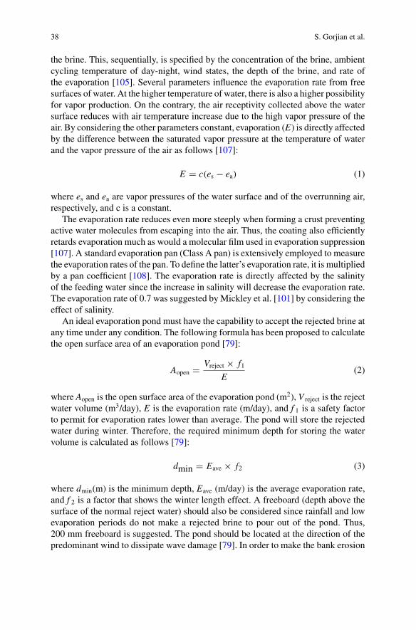
38 S. Gorjian et al.
the brine. This, sequentially, is specified by the concentration of the brine, ambientcycling temperature of day-night, wind states, the depth of the brine, and rate ofthe evaporation [105]. Several parameters influence the evaporation rate from freesurfaces of water. At the higher temperature of water, there is also a higher possibilityfor vapor production. On the contrary, the air receptivity collected above the watersurface reduces with air temperature increase due to the high vapor pressure of theair. By considering the other parameters constant, evaporation (E) is directly affectedby the difference between the saturated vapor pressure at the temperature of waterand the vapor pressure of the air as follows [107]:
E � c(es − ea) (1)
where es and ea are vapor pressures of the water surface and of the overrunning air,respectively, and c is a constant.
The evaporation rate reduces even more steeply when forming a crust preventingactive water molecules from escaping into the air. Thus, the coating also efficientlyretards evaporation much as would a molecular film used in evaporation suppression[107]. A standard evaporation pan (Class A pan) is extensively employed to measurethe evaporation rates of the pan. To define the latter’s evaporation rate, it is multipliedby a pan coefficient [108]. The evaporation rate is directly affected by the salinityof the feeding water since the increase in salinity will decrease the evaporation rate.The evaporation rate of 0.7 was suggested by Mickley et al. [101] by considering theeffect of salinity.
An ideal evaporation pond must have the capability to accept the rejected brine atany time under any condition. The following formula has been proposed to calculatethe open surface area of an evaporation pond [79]:
Aopen � Vreject × f1E
(2)
where Aopen is the open surface area of the evaporation pond (m2), V reject is the rejectwater volume (m3/day), E is the evaporation rate (m/day), and f 1 is a safety factorto permit for evaporation rates lower than average. The pond will store the rejectedwater during winter. Therefore, the required minimum depth for storing the watervolume is calculated as follows [79]:
dmin � Eave × f2 (3)
where dmin(m) is the minimum depth, Eave (m/day) is the average evaporation rate,and f 2 is a factor that shows the winter length effect. A freeboard (depth above thesurface of the normal reject water) should also be considered since rainfall and lowevaporation periods do not make a rejected brine to pour out of the pond. Thus,200 mm freeboard is suggested. The pond should be located at the direction of thepredominant wind to dissipate wave damage [79]. In order to make the bank erosion
Feasible Solar Applications for Brines Disposal in Desalination … 39
minimized, an inside slope of 1:5 has been suggested while the outside bank can befabricated at a slope of 1:2.
Suitable site selection is also another critical parameter since the ponds placedin light and loose soils cause leakage causing salts to move into the groundwater[79]. As has been seen from the studies carried out on solar ponds, for deep bodies(with the depth of 2–6 m) the salts crystallize in a slow, low temperature, and moreisothermal way. For shallow bodies (<2 m), the evaporation is alternately rapid, andday-night crystallization impacts are more notable [105].
Raising the temperature of water in the solar pond increases the evaporation rateswhich lead to increase in vapor pressure difference between the atmosphere andwater surface, decreasing surface tension or the bonds between the water moleculesthat finally can increase the evaporation rate and consequently the productivity ofthe pond. The other options are increasing the surface area exposed to air, increasingthe wind speed, surface roughness, and stirring the pond [79, 102].
6.2 Enhanced Solar Evaporation Ponds
Raising the brine evaporation rate in solar saltworks not only can decrease energycosts and improve the efficiency, but also provide an appropriate processing envi-ronment [103]. Till now, several experimental works and theoretical analysis havereported the use of solar energy for enhancing the brine evaporation in solar salt-works in the literature. The reported results have shown that the efficiency of thesolar evaporators is directly depended on the optical absorptivity of the saline water[103]. Several researchers have studied the possibility of adding dye to the brineand saline water to maximize the absorption of solar energy and, therefore, increasethe water temperature results in lower surface tension, higher saturation vapor pres-sure, and subsequently higher evaporation rate. The researchers recommended theaddition of three and a half dye grains per cubic foot of volume of the brine [109].Collares-Pereira et al. [110] developed and tested a prototype based on a passive solardryer for a MED desalination plant brine salt harvesting. A numerical model wasalso developed to describe the brine evaporation process inside the advanced solardryer (ASD). A primary prototype composing of a covering evaporation channel wasfabricated and the operation conditions were monitored.
In their work, the preliminary ASD prototype was modified to the final design ofthe prototype to be installed at Lesvos. The final salt production results comparedto traditional saltwork and were used to validate the simulation model. Zeng et al.[90] demonstrated a new way to increase solar evaporation rate in saltworks byusing floating Fe3O4/C magnetic particles as the light-absorbing materials. These500 nm particles were synthesized using carbonization of polyfurfuryl alcohol (PFA)incorporated with nanoparticles of Fe3O4. The Fe3O4/C nanoparticles were floatableon water due to a bulk particle density of 0.53 g/cm3 and being hydrophobicity. Theresults showed that Fe3O4/C particles improved the evaporation rate up to 2.3 timesand evaporation of 3.5% salt water.
40 S. Gorjian et al.
O’Reilly [111] developed a pilot-scale collector plate to assess the capabilitiesof the collector in enhancing the evaporation rate. To increase the evaporation rateof synthetic brine wastewater, a 14-month experimental program was undertaken toassess the ability of the unit under different operational parameters. The evaporationrate enhancement was investigated under themeteorological parameters of solar irra-diation, ambient temperature, wind velocity, and relative humidity with film heightsof 0.15, 0.2, and 0.3 mm and brine concentrations of 3.5, 7.0, and 12.5% NaCl ofthe brine. The final results showed that in relative humidities less than 40%, receivedsolar radiationmore than 20MJ/m2/day, constant wind velocities from 1.1 to 1.3m/s,and average daily ambient temperatures higher than 25 °C results in evaporation ratioenhancement between 2.0 and 3.0 in brine concentrations up to 7.0% NaCl.
The solar evaporative crystallization process was studied by Kasedde et al. [103]at Lake Katwe by evaluating brine evaporation rates and thermal efficiency of thesystem. In addition, an analysis was done to evaluate the probability of incensementin productivity of the solar evaporation ponds by implementing of a parabolic solarconcentrator. Final results indicated that the evaporation rates of the brine and thesalt pan temperature are directly affected by weather conditions of the location.
The system composed of a solar concentrator, a tank for storing the working fluid,and a heat exchanger (HE). In the proposed system, incoming solar radiation wasturned to the heat via the concentrator. The working fluid is circulated among thereceiver’s tube where it absorbs heat and transfers it into the storage tank. The hotworking fluid is then transferred to the HE. In the HE, the heat was transferred tothe brine which is pumped from the pan. The hot brine is then sprayed back over theopen surface of the salt pan at temperatures which are higher and, therefore, causingthe evaporation rate enhancement.
The evaporation rate could also be increased by locating light-absorbing agentson the surface or bottom of the solar ponds. Till now, several materials includedifferent dyes, blackened wet jute cloth, plastic bubble sheets in black color, blackrubber, and floating porous plates, etc. have been used to enhance the evaporationrate, but using these materials is quite limited. Horri et al. [112] have studied the useof solar light-absorbing carbon–Fe3O4 particles and reported that they can enhancethe evaporation rate by 230%. In their work, the evaporation process was enhancedby the hydrophobic floating light-absorbing porous materials was mathematicallymodeled, and thermal energy loss mechanisms were mathematically expressed. Theresult showed that by employing 0.045, 0.023, and 0.015 g of the light-absorbingmaterial, the evaporation rate increases by approximate factors of 2.3, 2, and 1.8,respectively.
6.3 Salinity-Gradient Solar Ponds
A salinity-gradient solar pond (SGSP) is a body of water which is warmed by absorb-ing solar radiation and because of its specific structure can supply longstanding heatstorage. The SGSPs differ from the most natural bodies of water since they are strati-
Feasible Solar Applications for Brines Disposal in Desalination … 41
fied artificially, and so, the bottom temperature of the ponds is higher than the surface[113]. An SGSP accumulate solar energy in the form of heat and stores it with thestability which is kept by the salt [114].
6.3.1 Working Principle of the SGSPs
The SGSPs are fabricated for deposit of salts and high concentrate brines so thatsalts like magnesium chloride (MgCl2), sodium nitrate (NaNO3), sodium sulfate(Na2SO4), and NaCl, etc. are precipitated at the base of the pond [105, 114]. Atypical SGSP is mainly comprised of three individual layers [113]: upper convectivezone (UCZ), non-convective zone (NCZ), and lower convective zone (LCZ) [115].Ascan be seen in the figure, UCZ and LCZ have the unite and fixed temperature and saltconcentrations, while in NCZ, these increase with depth [114]. The UCZ is a ratherthin layer of water with a little salt concentration which is instantly connected to theabove-collected air and, therefore, is at the ambient temperature. The NCZ keeps theupper and bottom layers thermally separated from each other. The NCZ is likely themost dominant layer in the pond since it represses total convection inside the pond.The salt content in this layer is higher, and it is denser than the upper layer [113,116]. The LCZ has a high salt gradient that sustains the fluid inside the pond and isheated by absorbing solar radiation. The LCZ attains the highest temperature insidethe pond [113, 115]. To keep the salt gradient constant, freshwater should be addedfrom the top and the concentrated brine from the bottom of the pond simultaneously[114].
In UCZ, almost 45% of receiving solar radiation is absorbed, and the rest is lost inthe form of evaporation, convection, and reflection. In NCZ, because of the existenceof salinity gradient, the warmer water cannot ascent to the surface and cools down asin a normal pond, and thus, heat losses happen only because of heat conduction [114].Depending upon the NCZ thickness, about 15–25% of the solar radiation absorptionoccurs in this layer. By having a blackened surface at the bottom of the pond, up to40% of the whole received solar radiation can be absorbed by LCZ, and thus, thetemperature of this zone ranges from 80 to 90 °C [113, 114, 116].
Due to the mentioned heat transfer mechanisms in an SGSP, the evaporation ratesare more significant than those occurring in natural water bodies. Besides, one ofthe disadvantages of the solar ponds is losing the water since it evaporates which islinked to the heat losses from the pond surface [113].
6.3.2 Applications of the SGSPs
The stored energy in SGSPs can be used for appropriate thermal applications includedesalination, refrigeration, process heating, drying, and solar power generation [105,114, 117]. Temperature levels higher than 80 °C can be gained inmany SGSPs aroundthe world. Moreover, the collected energy in these ponds can also be utilized for low-temperature applications such as air and water heating [113, 115]. In general, the
42 S. Gorjian et al.
brine discharge from the desalination plants, such as membrane filtration and ED,can be reused to recharge the pond. In addition, a thermal desalination technique canalso be used to treat the brine concentrate rejected from desalination plants (such asMSF/MED). The brine discharge from the thermal desalination plants can be fed to abrine concentrator which makes a slurry composed of saturated brine and crystals ofthe salt [117]. Both thermal desalination plants and brine concentrator can be poweredby the thermal energy derived from the SGSPs. In this case, the brine discharge fromthe desalination plants can add to the pond capacity be recharging the solar pond. Suchsystem addresses two serious environmental impactswhich include brine concentratereuse and a sustainable energy source supply for desalination processes [117, 118].The use of an SGSP will be favorable if low-cost land and arid climate are bothavailable since the production depends on the location of the ponds. The studieshave proved that the SGSP’s efficiency is between 10 and 30% if the temperatureof the storage zone is 40–80 °C [114]. However, due to increases in the demand ofsome salts and an increase in operating and capital costs, it has been forced to givea more scientific focus for design and operation of SGSPs [118].
7 Conclusion
Water is an essential element for animals and human activities. Freshwater productionhas become a global concern for several communities, estimated population growthand integrated demand overpass currently accessible water resources. As a result ofrising interest in desalination, the concernment about the probable environmentalimpacts has also grown since the brine discharge has higher potential to adverselyimpact on ecological and physicochemical properties of the receiving environments.
This chapter has reviewed the sustainable brine disposal methods with more focuson solar-assisted technologies. Several commercial ways are now implementingworldwide to harvest salt from brine effluent discharge from the desalination plants.Using solar energy as a renewable source of power can both imitate the environmen-tal impacts of the conventional brine disposal methods and enhance the evaporationrate of the solar evaporation ponds.
Evaporation pond is relatively easy to construct and operatewithminimalmechan-ical or operator input. The ponds should spread over large surface areas to increasethe evaporation rate. If the rate of evaporation be enhanced, the need for the sameamount of land would be reduced. An enhanced rate of evaporation would havetwo advantages: the flexibility to increase the amount of brine wastewater “pushed”through an evaporation pond, and a reduced amount of land that would be needed toachieve the same rate of evaporation.
Feasible Solar Applications for Brines Disposal in Desalination … 43
References
1. Tansel B (2008) New technologies for water and wastewater treatment: a survey of recentpatents. Recent Patents Chem Eng 1(1):17–26
2. Ambashta RD, Sillanpää M (2010) Water purification using magnetic assistance: a review. JHazard Mater 180(1–3):38–49
3. Ackah M, Agyemang O, Anim AK, Osei J, Bentil NO, Kpattah L, Gyamfi ET, HansonJEK (2011) Assessment of groundwater quality for drinking and irrigation: the case study ofTeiman-Oyarifa community, Ga East municipality, Ghana. Proc Int Acad Ecol Environ Sci1(3–4):186–194
4. Huang X, Sillanpää M, Duo BU, Gjessing ET (2008) Water quality in the Tibetan Plateau:metal contents of four selected rivers. Environ Pollut 156(2):270–277
5. Ferguson CM, Charles K, Deere DA (2008) Quantification of microbial sources in drinking-water catchments. Crit Rev Environ Sci Technol 39(1):1–40
6. ZhangY, LoveN, EdwardsM (2009) Nitrification in drinkingwater systems. Crit Rev EnvironSci Technol 39(3):153–208
7. Ahmed MI, Hrairi M, Ismail AF (2009) On the characteristics of multistage evacuated solardistillation. Renew Energy 34(6):1471–1478
8. MacLaughlin C (2000) IDA worldwide desalting plants inventory. International DesalinationAssociation, USA
9. El-Dessouky HTHT, Ettouney HMHM (2002) Fundamentals of salt water desalination. Else-vier
10. Zhang W, Jiang F, Ou J (2011) Global pesticide consumption and pollution: with China as afocus. Proc Int Acad Ecol Environ Sci 1(2):125
11. Hietanen J (2016) Environmental impacts of desalination technologies12. Kargari A, Shirazi MMA (2014) Water desalination: solar-assisted membrane distillation. In:
Encyclopedia of energy engineering and technology, vol 4. CRC Press, USA13. Marcovecchio MG, Mussati SF, Aguirre PA, Nicolás J (2005) Optimization of hybrid desali-
nation processes including multi stage flash and reverse osmosis systems. Desalination182(1–3):111–122
14. Kaur V, Mahajan R (2016)Water crisis: towards a way to improve the situation. RituMahajanInt J Eng Technol Sci Res IJETSR 3(6):2394–3386. www.ijetsr.com
15. DasR,Hamid SBA,AliME, Ismail AF,AnnuarMSM,Ramakrishna S (2014)Multifunctionalcarbon nanotubes in water treatment: the present, past and future. Desalination 354:160–179
16. Karagiannis IC, Soldatos PG (2008)Water desalination cost literature: review and assessment.Desalination 223(1–3):448–456
17. Dore MHI (2005) Forecasting the economic costs of desalination technology. Desalination172(3):207–214
18. FalkenmarkM,Widstrand C (1992) Population and water resources: a delicate balance. PopulBull 47(3):1–36
19. Fritzmann C, Löwenberg J, Wintgens T, Melin T (2007) State-of-the-art of reverse osmosisdesalination. Desalination 216(1–3):1–76
20. Sousa P, Soares A, Monteiro E, Rouboa A (2014) A CFD study of the hydrodynamics in adesalination membrane filled with spacers. Desalination 349:22–30
21. Azimibavil S, Dehkordi AJ (2016) Dynamic simulation of a multi-effect distillation (MED)process. Desalination 392:91–101
22. ElimelechM, PhillipWA, Service RF, ShannonMA, Schiermeier Q, FritzmannC, LowenbergJ, Wintgens T, Melin T, von Medeazza GLM, Dreizin Y, Tenne A, Hoffman D, Tal A, SemiatR, Busch M, Mickols WE, Spiegler KS, El-Sayed YM, Stoughton RW, Lietzke MH, StoverRL, Zhu AZ, Christofides PD, Cohen Y, Song LF, Wilf M, Lee KP, Arnot TC, Mattia D,Larson RE, Cadotte JE, Petersen RJ, Paul DR, Geise GM, Park HB, Sagle AC, Freeman BD,McGrath JE, Glater J, Hong SK, ElimelechM, Holt JK, Majumder M, Chopra N, Andrews R,Hinds BJ, KumarM,GrzelakowskiM, Zilles J, ClarkM,MeierW, Corry B, FalkK, Sedlmeier
44 S. Gorjian et al.
F, Joly L, Netz RR, Bocquet L, Johnson J, Busch M, Ostuni E, Chapman RG, Holmlin RE,Takayama S, Whitesides GM, Kang S, Asatekin A, Mayes AM, Elimelech M, Elimelech M,Zhu XH, Childress AE, Hong SK, Jiang SY, Cao ZQ, Siegers C, Biesalski M, Haag R, CallowJA, Callow ME, Park HB, Freeman BD, Zhang ZB, Sankir M, McGrath JE, Zhou MJ, CathTY, Hancock NT, Lundin CD, Hoppe-Jones C, Drewes JE, Kim SJ, Ko SH, Kang KH, Han J,Gilron J, Song LF, Sirkar KK, McCutcheon JR, McGinnis RL, Elimelech M, McGinnis RL,Elimelech M, Koros WJ, Raluy G, Serra L, Uche J, Lattemann S, Hopner T, Pacheco FA,Pinnau I, Reinhard M, Leckie JO, Tang CYY, Kwon YN, Leckie JO, Coronell O, Mariñas BJ,Zhang XJ, Cahill DG (2011) The future of seawater desalination: energy, technology, and theenvironment. Science (80-.) 333(6043):712–717
23. WilderMO,Aguilar-Barajas I, Pineda-PablosN,VaradyRG,Megdal SB,McEvoy J,MeridethR, Zúñiga-Terán AA, Scott CA (2016) Desalination and water security in the US–Mex-ico border region: assessing the social, environmental and political impacts. Water Int8060(April):1–20
24. Milly PCD, Betancourt J, Falkenmark M, Hirsch RM, Kundzewicz ZW, LettenmaierDP, Stouffer RJ (2008) Stationarity is dead: whither water management? Science (80-.)319(5863):573–574
25. Tsiourtis NX (2001) Desalination and the environment. Desalination 141(3):223–23626. McEvoy J (2014) Desalination and water security: the promise and perils of a technological
fix to the water crisis in Baja California Sur, Mexico. 7(3):518–54127. Council NR (2008) Desalination: a national perspective. National Academies Press28. Cooley H, Gleick P, Wolff G (2006) Desalination, with a grain of salt: perspectives from
California. Pacific Inst, Berkeley, CA29. Yu T-H, Shiu H-Y, Lee M, Chiueh P-T, Hou C-H (2016) Life cycle assessment of envi-
ronmental impacts and energy demand for capacitive deionization technology. Desalination399:53–60
30. Gorjian S, Ghobadian B (2015) Solar desalination: a sustainable solution to water crisis inIran. Renew Sustain Energy Rev 48:571–584
31. Virgili F, PankratzT,Gasson J (2016) IDAdesalination yearbook 2015–2016.MediaAnalyticsLimited
32. Wang H, Xu X, Zhu G (2015) Landscape changes and a salt production sustainableapproach in the state of salt pan area decreasing on the coast of Tianjin, China. Sustainable7(8):10078–10097
33. McEvoy J,WilderM (2012)Discourse and desalination: potential impacts of proposed climatechange adaptation interventions in the Arizona-Sonora border region. Glob Environ Change22(2):353–363
34. Scott CA, Pasqualetti MJ (2010) Energy and water resources scarcity: critical infrastructurefor growth and economic development in Arizona and Sonora. Nat Resour J 645–682
35. ElimelechM, Phillip WA (2011) The future of seawater desalination: energy, technology, andthe environment. Science (80-.) 333(6043):712–717
36. Li C, Goswami Y, Stefanakos E (2013) Solar assisted sea water desalination: a review. RenewSustain Energy Rev 19:136–163
37. Shatat M, Worall M, Riffat S (2013) Opportunities for solar water desalination worldwide:review. Sustain Cities Soc 9:67–80
38. MezherT, FathH,AbbasZ,KhaledA (2011)Techno-economic assessment and environmentalimpacts of desalination technologies. Desalination 266(1–3):263–273
39. Deng R, Xie L, Lin H, Liu J, Han W (2010) Integration of thermal energy and seawaterdesalination. Energy 35(11):4368–4374
40. Al-Karaghouli A, Kazmerski LL (2013) Energy consumption and water production cost ofconventional and renewable-energy-powered desalination processes. Renew Sustain EnergyRev 24:343–356
41. Goosen MFA, Mahmoudi H, Ghaffour N, Bundschuh J, Al Yousef Y (2016) A critical evalu-ation of renewable energy technologies for desalination. In: Application of materials scienceand environmental materials (AMSEM2015), pp 233–258
Feasible Solar Applications for Brines Disposal in Desalination … 45
42. Ghaffour N, Bundschuh J, Mahmoudi H, Goosen MFA (2015) Renewable energy-drivendesalination technologies: a comprehensive review on challenges and potential applicationsof integrated systems. Desalination 356:94–114
43. Ghaffour N, Lattemann S, Missimer T, Ng KC, Sinha S, Amy G (2014) Renewable energy-driven innovative energy-efficient desalination technologies. Appl Energy 136:1155–1165
44. Younos T (2009) Environmental issues of desalination. J Contemp Water Res Educ132(1):11–18
45. Miller JE (2003) Review of water resources and desalination techniques. Sand report no.March, pp 1–54
46. Bombar G, Dölgen D, Alpaslan MN (2015) Environmental impacts and impact mitigationplans for desalination facilities. Desalin Water Treat 3994(April):1–12
47. Einav R, Harussi K, Perry D (2003) The footprint of the desalination processes on the envi-ronment. Desalination 152(1–3):141–154
48. “WaterDesalinationUsingRenewable Energy,” 2012. IEA-ETSAP and IRENA©TechnologyBrief I12. 1–28
49. Burn S, Hoang M, Zarzo D, Olewniak F, Campos E, Bolto B, Barron O (2015) Desalina-tion techniques—a review of the opportunities for desalination in agriculture. Desalination364:2–16
50. Subramani A, Badruzzaman M, Oppenheimer J, Jacangelo JG (2011) Energy minimiza-tion strategies and renewable energy utilization for desalination: a review. Water Res45(5):1907–1920
51. Dawoud MA (2012) Environmental impacts of seawater desalination: Arabian Gulf casestudy. Int J Environ Sustain 1(3)
52. “Renewable EnergyDesalination An Emerging Solution to Close theWater Gap in theMiddleEast and North Africa,” World Bank Publications, USA, Washington D. C., 2012
53. W. Canter L, (1996). Environmental impact assessment. McGraw-Hill, New York. p. 66054. Shahabi MP, Anda M, Ho G (2015) Influence of site-specific parameters on environmental
impacts of desalination. Desalin Water Treat 55(9):2357–236355. Sommariva C, Hogg H, Callister K (2004) Environmental impact of seawater desalina-
tion: relations between improvement in efficiency and environmental impact. Desalination167(1–3):439–444
56. Zhao Y, Min Hu X, Hui Jiang B, Li L (2014) Optimization of the operational parametersfor desalination with response surface methodology during a capacitive deionization process.Desalination 336(1):64–71
57. Singh GK (2013) Solar power generation by PV (photovoltaic) technology: a review. Energy53:1–13
58. Tyagi VV, Rahim NAA, Rahim NA, Selvaraj JAL (2013) Progress in solar PV technology:research and achievement. Renew Sustain Energy Rev 20:443–461
59. Abujazar MSS, Fatihah S, Rakmi AR, Shahrom MZ (2016) The effects of design parameterson productivity performance of a solar still for seawater desalination: a review. Desalination385:178–193
60. Nagaraj R, Thirugnanamurthy D, Rajput MM, Panigrahi BK (2016) Techno-economic analy-sis of hybrid power system sizing applied to small desalination plants for sustainable operation.Int J Sustain Built Environ 5(2):269–276
61. Manju S, Sagar N (2017) Renewable energy integrated desalination: a sustainable solutionto overcome future fresh-water scarcity in India. Renew Sustain Energy Rev 73(December2016):594–609
62. Kalogirou S (2005) Seawater desalination using renewable energy sources. Prog EnergyCom-bust Sci 31(3):242–281
63. Delyannis E (2003) Historic background of desalination and renewable energies. Sol Energy75(5):357–366
64. Cipollina A, Tzen E, Subiela V, Papapetrou M, Koschikowski J, Schwantes R (2015) Renew-able energy desalination: performance analysis and operating data of existing RES desalina-tion plants. Desalin Water Treat 55(11):3126–3146
46 S. Gorjian et al.
65. Xevgenos D, Moustakas K, Malamis D, Loizidou M (2016) An overview on desalination &sustainability: renewable energy-driven desalination and brine management. Desalin WaterTreat 57(5):2304–2314
66. Caldera U, Bogdanov D, Breyer C (2016) Local cost of seawater RO desalination based onsolar PV and wind energy: a global estimate. Desalination 385:207–216
67. Jijakli K, Arafat H, Kennedy S, Mande P, Theeyattuparampil VV (2012) How green solardesalination really is? Environmental assessment using life-cycle analysis (LCA) approach.Desalination 287:123–131
68. Manju S, Sagar N (2017) Renewable energy integrated desalination: a sustainable solu-tion to overcome future fresh-water scarcity in India. Renew Sustain Energy Rev 73(Jan-uary):594–609
69. Chaibi MT (2000) An overview of solar desalination for domestic and agriculture water needsin remote arid areas. Desalination 127(2):119–133
70. SharonH, ReddyKS (2015) A review of solar energy driven desalination technologies. RenewSustain Energy Rev 41:1080–1118
71. Kalogirou S (2009) Solar energy engineering: processes and systems. Academic Press72. Chandrashekara M, Yadav A (2017) Water desalination system using solar heat: a review.
Renew Sustain Energy Rev 67:1308–133073. Qiblawey HHM, Banat F (2008) Solar thermal desalination technologies. Desalination
220(1–3):633–64474. Roberts DA, Johnston EL, Knott NA (2010) Impacts of desalination plant discharges on the
marine environment: a critical review of published studies. Water Res 44(18):5117–512875. Singh R, Hankins N (2016) Emerging membrane technology for sustainable water treatment.
Elsevier76. Sedivy VM (2009) Environmental balance of salt production speaks in favour of solar salt-
works. Glob NEST J 11(1):41–4877. Abdulsalam A, Idris A, Mohamed TA, Ahsan A (2016) An integrated technique using solar
and evaporation ponds for effective brine disposal management. Int J Sustain Energy 1–1278. Morillo J, Usero J, Rosado D, El Bakouri H, Riaza A, Bernaola F-JJ (2014) Comparative
study of brine management technologies for desalination plants. Desalination 336(1):32–4979. Ahmed M, Shayya WH, Hoey D, Mahendran A, Morris R, Al-Handaly J (2000) Use of
evaporation ponds for brine disposal in desalination plants. Desalination 130(2):155–16880. Chelme-Ayala P, Smith DW, El-DinMG (2013) Membrane concentrate management options:
a comprehensive critical review. J Environ Eng Sci 8(3):326–33981. Pérez-González A, Urtiaga AM, Ibáñez R, Ortiz I (2012) State of the art and review on the
treatment technologies of water reverse osmosis concentrates. Water Res 46(2):267–28382. Mohamed AMO, Maraqa M, Al Handhaly J (2005) Impact of land disposal of reject brine
from desalination plants on soil and groundwater. Desalination 182(1–3):411–43383. Mickley M (2001) Membrane concentrate disposal: practices and regulation. US Department
of the Interior, Bureau of Reclamation, Technical Service Center, Water Treatment Engineer-ing and Research Group Boulder, Colo
84. AhmadN, Baddour RE (2014) A review of sources, effects, disposal methods, and regulationsof brine into marine environments. Ocean Coast Manage 87:1–7
85. Shahmansouri A, Min J, Jin L, Bellona C (2015) Feasibility of extracting valuable mineralsfrom desalination concentrate: a comprehensive literature review. J Clean Prod 100:4–16
86. Kimes JK (1995) The regulation of concentrate disposal in Florida.Desalination 102(1):87–9287. Tong T, Elimelech M (2016) The global rise of zero liquid discharge for wastewater manage-
ment: drivers, technologies, and future directions. Environ Sci Technol 50(13):6846–685588. Mashaly AF, Alazba AA, Al-Awaadh AM (2016) Assessing the performance of solar desali-
nation system to approach near-ZLD under hyper arid environment. Desalin Water Treat57(26):12019–12036
89. Balasubramanian P (2013) A brief review on best available technologies for reject water(brine) management in industries. Int J Environ Sci 3(6):2010–2018
Feasible Solar Applications for Brines Disposal in Desalination … 47
90. ZengY,Yao J, Horri BA,WangK,WuY, LiD,WangH (2011) Solar evaporation enhancementusing floating light-absorbing magnetic particles. Energy Environ Sci 4(10):4074
91. Tamimi A, Rawajfeh K (2007) Lumped modeling of solar-evaporative ponds charged fromthe water of the Dead Sea. Desalination 216(1–3):356–366
92. Laspidou C, Hadjibiros K, Gialis S (2010)Minimizing the environmental impact of Sea Brinedisposal by coupling desalination plants with solar saltworks: a case study for Greece. Water2(1)
93. Madkour FF, GaballahMM (2012) Phytoplankton assemblage of a solar saltern in Port Fouad,Egypt. Oceanologia 54(4):687–700
94. Katzir L, Volkmann Y, Daltrophe N, Korngold E, Mesalem R, Oren Y, Gilron J (2010)WAIV-Wind aided intensified evaporation for brine volume reduction and generatingmineral byprod-ucts. Desalin Water Treat 13(1–3):63–73
95. Korovessis NA, Lekkas TD (1999) Solar saltworks production process evolution-wetlandfunction. In: Proceedings of the post conference symposiumSALTWORKS: preserving salinecoastal ecosystems-global NEST, 11–30 Sep 1999
96. Davis JS (2000) Structure, function, and management of the biological system for seasonalsolar saltworks. Glob NEST J 2(3):217–226
97. Costa LT, Farinha JC, Hecker N, Tomàs Vives P (1996) Mediterranean wetland inventory: areference manual. Inst. da Conserv. da Nat. y Wetl. Int. Lisboa, Port
98. Ahmed M, Shayya WH, Hoey D, Al-Handaly J (2001) Brine disposal from reverse osmosisdesalination plants in Oman and the United Arab Emirates. Desalination 133(2):135–147
99. Sánchez AS, Nogueira IBR, Kalid RA (2015) Uses of the reject brine from inland desalinationfor fish farming, Spirulina cultivation, and irrigation of forage shrub and crops. Desalination364:96–107
100. “San Francisco’s Incredible Stained Glass Salt Ponds.” [Online]. Available: http://scribol.com/travel/cities-travel/san-franciscos-incredible-stained-glass-salt-ponds/. Accessed: 22-Sep-2018
101. Mickley M, Hamilton R, Gallegos L, Truesdall J (1993) Membrane concentration disposal.Am Water Work Assoc Res Found Denver Color
102. Salzman SA, Allinson G, Stagnitti F, Coates M, Hill RJ (2001) Performance of constructedevaporation ponds for disposal of smelter waste water: a case study at Portland Aluminum,Victoria, Australia. Water Res 35(9):2121–2128
103. Kasedde H, Lwanyaga JD, Kirabira JB (2014) Optimization of solar energy for salt extractionfrom Lake Katwe, Uganda. Glob NEST J 16(6):1152–1168
104. Malaeb L, Ayoub GM (2011) Reverse osmosis technology for water treatment: state of theart review. Desalination 267(1):1–8
105. El-Badry H (2013) Development of solar ponds optimization model: arab potash solar sys-tem—a case study. Nat Resour 04:82–91
106. OrenA (2009) Saltern evaporation ponds asmodel systems for the study of primary productionprocesses under hypersaline conditions. Aquat Microb Ecol 56(2–3):193–204
107. Turk LJ (1970) Evaporation of brine: a field study on the Bonneville Salt Flats, Utah. WaterResour Res 6(4):1209–1215
108. Ahmed M, Arakel A, Hoey D, Thumarukudy MR, Goosen MFA, Al-Haddabi M, Al-BelushiA (2003) Feasibility of salt production from inland RO desalination plant reject brine: a casestudy. Desalination 158(1–3):109–117
109. Hoque S, Alexander T, Gurian P (2009) Innovative inland brine disposal options, pp 1–13110. Pereira MC, Mendes JF, Horta P, Korovessis N (2007) Final design of an advanced solar
dryer for salt recovery from brine effluent of an MED desalination plant. Desalination211(1–3):222–231
111. O’Reilly D (2009) Evaporation enhancement from evaporation ponds using collector plateunits
112. Horri BA, Chong MN, Chen XD, Wang H (2014) Modelling of solar evaporation assisted byfloating light-absorbing porous materials, pp 73–81

48 S. Gorjian et al.
113. Silva C, González D, Suárez F (2017) An experimental and numerical study of evaporationreduction in a salt-gradient solar pond using floating discs. Sol Energy 142:204–214
114. Velmurugan V, Srithar K (2008) Prospects and scopes of solar pond: a detailed review. RenewSustain Energy Rev 12(8):2253–2263
115. Simic M, George J (2017) Design of a system to monitor and control solar pond: a review.Energy Proc 110:322–327
116. Rizvi R, Jamal Y, Ghauri MB, Salman R, Khan I (2015) Solar pond technology for brinemanagement and heat extraction: a critical review. J Fac Eng Technol 22(2):69–79
117. Nakoa K, Rahaoui K, Date A, Akbarzadeh A (2016) Sustainable zero liquid discharge desali-nation (SZLDD). Sol Energy 135:337–347
118. Cisternas L, Pinto P,OssandónK (2009) Planning and scheduling of solar salt harvest. ComputAided Chem Eng 26:417–422
Effect of Design Parameterson Productivity of Various Passive SolarStills
Ajay Kumar Kaviti, Anil Kumar and Om Prakash
Abstract Fresh water and shortage of conventional energy are two major problemsof the world. Water is the basic necessity for sustenance of all living entities. Humanbeings are considered most refined living entities. They need clean and fresh waterfor their sustenance at less consumption of conventional energy or by consumption ofrenewable energy. In this perspective,many non-renewable and renewable techniqueshave been developed for the purification of brackish or saline water. Among manywater purification techniques, domestic solar still is most attractive and sustainablemethod to cater the need of fresh drinkable water in distant areas at a reasonablecost. Any amount of effort to improve the yield from solar stills by consideringvarious design parameters is worth to discuss. In the last three decades, so manydesign parameters are considered to improve the productivity of fresh water. Variousdesigns and design parameters used by researchers to improve the productivity ofsolar stills were reviewed in this chapter for passive solar stills.
Keywords Solar stills · Desalination · Design parameters · Productivity
1 Introduction
Water is one of the most essential and basic requirements for the sustenance of allliving entities like human beings, animals, birds and trees. Freshwater availabilityis less than 1%, and it is decreasing day by day due to pollution and increasingindustrial revolution and increase in unwanted population [1]. In today’s world,
A. K. Kaviti (B)Department of Mechanical Engineering, VNR Vignana Jyothi Institute of Engineeringand Technology, Hyderabad, Indiae-mail: [email protected]
A. KumarDepartment of Mechanical Engineering, Delhi Technological University, Delhi 110042, India
O. PrakashDepartment of Mechanical Engineering, Birla Institute of Technology, Mesra,Ranchi 835215, India
© Springer Nature Singapore Pte Ltd. 2019A. Kumar and O. Prakash (eds.), Solar Desalination Technology,Green Energy and Technology, https://doi.org/10.1007/978-981-13-6887-5_3
49
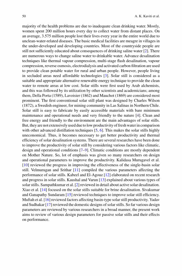
50 A. K. Kaviti et al.
majority of the health problems are due to inadequate clean drinking water. Mostly,women spent 200 million hours every day to collect water from distant places. Onan average, 3.575 million people lost their lives every year in the entire world due tounclean-water-related diseases. The basic medical facilities are meagre in villages inthe under-developed and developing countries. Most of the countryside people arestill not sufficiently educated about consequences of drinking saline water [2]. Thereare numerous ways to change saline water to drinkable water. Advance desalinationtechniques like thermal vapour compression, multi-stage flash desalination, vapourcompression, reverse osmosis, electrodialysis and activated carbon filtration are usedto provide clean potable water for rural and urban people. However, people livingin secluded areas need affordable technologies [3]. Solar still is considered as asuitable and appropriate alternative renewable energy technique to provide the cleanwater to remote areas at low cost. Solar stills were first used by Arab alchemists,and this was followed by its utilization by other scientists and academicians; amongthem, Della Porta (1589), Lavoisier (1862) and Mauchot (1869) are considered mostprominent. The first conventional solar still plant was designed by Charles Wilson(1872), a Swedish engineer, for mining community in Las Salinas in Northern Chile.Solar still is easy to fabricate by easily accessible materials with bare minimummaintenance and operational needs and very friendly to the nature [4]. Clean andfree energy and friendly to the environment are the main advantages of solar stills.But, they are not extensively useddue to lowproductivity of freshwater in comparisonwith other advanced distillation techniques [5, 6]. This makes the solar stills highlyuneconomical. Thus, it becomes necessary to get better productivity and thermalefficiency of solar desalination systems. There are several researches have been doneto improve the productivity of solar still by considering various factors like climatic,design and operational conditions [7–9]. Climatic conditions are mostly dependenton Mother Nature. So, lot of emphasis was given so many researchers on designand operational parameters to improve the productivity. Kalidasa Murugavel et al.[10] reviewed the progress in improving the effectiveness of the single-basin solarstill. Velmurugan and Srithar [11] compiled the various parameters affecting theperformance of solar stills. Kabeel and El-Agouz [12] elaborated on recent researchand progress in solar stills. Kaushal and Varun [13] explained about various types ofsolar stills. Sampathkumar et al. [2] reviewed in detail about active solar desalination.Xiao et al. [14] focused on the solar stills suitable for brine desalination. Sivakumarand Ganapathy Sundaram [15] reviewed techniques to improve solar still efficiency.Muftah et al. [16] reviewed factors affecting basin-type solar still productivity. Yadavand Sudhakar [17] reviewed the domestic designs of solar stills. So far various designparameters are reviewed by various researchers in a broad manner, the present workaims to review of various design parameters for passive solar stills and their effectson performance.
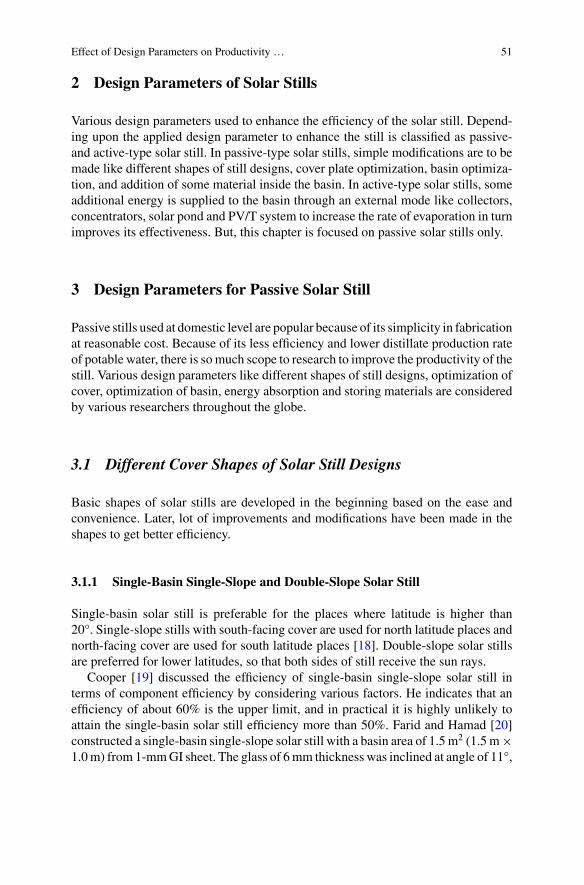
Effect of Design Parameters on Productivity … 51
2 Design Parameters of Solar Stills
Various design parameters used to enhance the efficiency of the solar still. Depend-ing upon the applied design parameter to enhance the still is classified as passive-and active-type solar still. In passive-type solar stills, simple modifications are to bemade like different shapes of still designs, cover plate optimization, basin optimiza-tion, and addition of some material inside the basin. In active-type solar stills, someadditional energy is supplied to the basin through an external mode like collectors,concentrators, solar pond and PV/T system to increase the rate of evaporation in turnimproves its effectiveness. But, this chapter is focused on passive solar stills only.
3 Design Parameters for Passive Solar Still
Passive stills used at domestic level are popular because of its simplicity in fabricationat reasonable cost. Because of its less efficiency and lower distillate production rateof potable water, there is somuch scope to research to improve the productivity of thestill. Various design parameters like different shapes of still designs, optimization ofcover, optimization of basin, energy absorption and storing materials are consideredby various researchers throughout the globe.
3.1 Different Cover Shapes of Solar Still Designs
Basic shapes of solar stills are developed in the beginning based on the ease andconvenience. Later, lot of improvements and modifications have been made in theshapes to get better efficiency.
3.1.1 Single-Basin Single-Slope and Double-Slope Solar Still
Single-basin solar still is preferable for the places where latitude is higher than20°. Single-slope stills with south-facing cover are used for north latitude places andnorth-facing cover are used for south latitude places [18]. Double-slope solar stillsare preferred for lower latitudes, so that both sides of still receive the sun rays.
Cooper [19] discussed the efficiency of single-basin single-slope solar still interms of component efficiency by considering various factors. He indicates that anefficiency of about 60% is the upper limit, and in practical it is highly unlikely toattain the single-basin solar still efficiency more than 50%. Farid and Hamad [20]constructed a single-basin single-slope solar still with a basin area of 1.5 m2 (1.5 m×1.0m) from 1-mmGI sheet. The glass of 6mm thickness was inclined at angle of 11°,
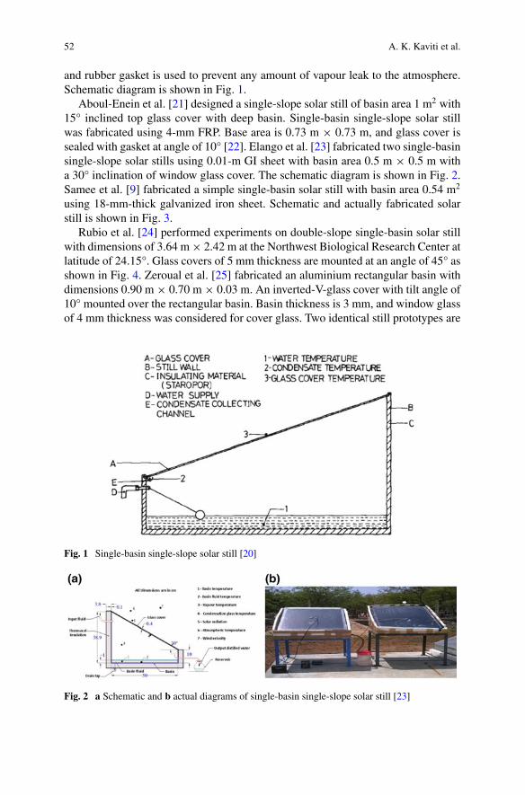
52 A. K. Kaviti et al.
and rubber gasket is used to prevent any amount of vapour leak to the atmosphere.Schematic diagram is shown in Fig. 1.
Aboul-Enein et al. [21] designed a single-slope solar still of basin area 1 m2 with15° inclined top glass cover with deep basin. Single-basin single-slope solar stillwas fabricated using 4-mm FRP. Base area is 0.73 m × 0.73 m, and glass cover issealed with gasket at angle of 10° [22]. Elango et al. [23] fabricated two single-basinsingle-slope solar stills using 0.01-m GI sheet with basin area 0.5 m × 0.5 m witha 30° inclination of window glass cover. The schematic diagram is shown in Fig. 2.Samee et al. [9] fabricated a simple single-basin solar still with basin area 0.54 m2
using 18-mm-thick galvanized iron sheet. Schematic and actually fabricated solarstill is shown in Fig. 3.
Rubio et al. [24] performed experiments on double-slope single-basin solar stillwith dimensions of 3.64 m× 2.42 m at the Northwest Biological Research Center atlatitude of 24.15°. Glass covers of 5 mm thickness are mounted at an angle of 45° asshown in Fig. 4. Zeroual et al. [25] fabricated an aluminium rectangular basin withdimensions 0.90 m× 0.70 m× 0.03 m. An inverted-V-glass cover with tilt angle of10° mounted over the rectangular basin. Basin thickness is 3 mm, and window glassof 4 mm thickness was considered for cover glass. Two identical still prototypes are
Fig. 1 Single-basin single-slope solar still [20]
Fig. 2 a Schematic and b actual diagrams of single-basin single-slope solar still [23]
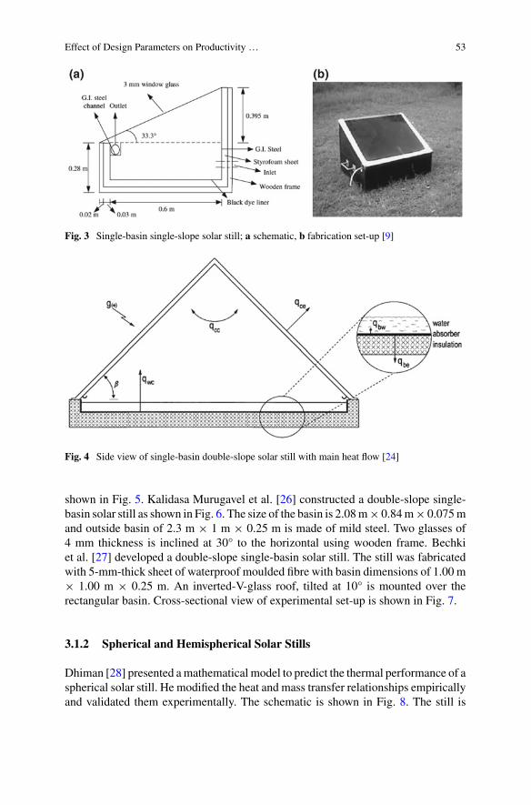
Effect of Design Parameters on Productivity … 53
Fig. 3 Single-basin single-slope solar still; a schematic, b fabrication set-up [9]
Fig. 4 Side view of single-basin double-slope solar still with main heat flow [24]
shown in Fig. 5. Kalidasa Murugavel et al. [26] constructed a double-slope single-basin solar still as shown in Fig. 6. The size of the basin is 2.08m× 0.84m× 0.075mand outside basin of 2.3 m × 1 m × 0.25 m is made of mild steel. Two glasses of4 mm thickness is inclined at 30° to the horizontal using wooden frame. Bechkiet al. [27] developed a double-slope single-basin solar still. The still was fabricatedwith 5-mm-thick sheet of waterproof moulded fibre with basin dimensions of 1.00 m× 1.00 m × 0.25 m. An inverted-V-glass roof, tilted at 10° is mounted over therectangular basin. Cross-sectional view of experimental set-up is shown in Fig. 7.
3.1.2 Spherical and Hemispherical Solar Stills
Dhiman [28] presented amathematical model to predict the thermal performance of aspherical solar still. He modified the heat and mass transfer relationships empiricallyand validated them experimentally. The schematic is shown in Fig. 8. The still is
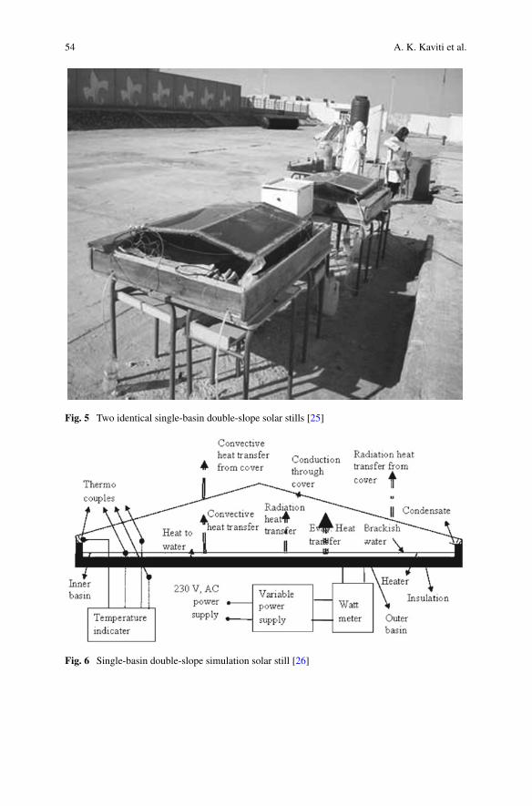
54 A. K. Kaviti et al.
Fig. 5 Two identical single-basin double-slope solar stills [25]
Fig. 6 Single-basin double-slope simulation solar still [26]
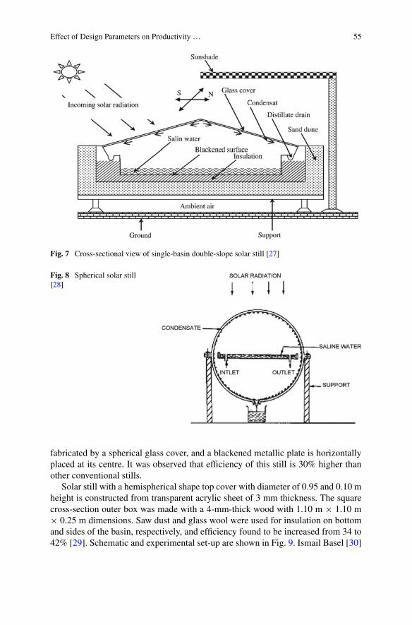
Effect of Design Parameters on Productivity … 55
Fig. 7 Cross-sectional view of single-basin double-slope solar still [27]
Fig. 8 Spherical solar still[28]
fabricated by a spherical glass cover, and a blackened metallic plate is horizontallyplaced at its centre. It was observed that efficiency of this still is 30% higher thanother conventional stills.
Solar still with a hemispherical shape top cover with diameter of 0.95 and 0.10 mheight is constructed from transparent acrylic sheet of 3 mm thickness. The squarecross-section outer box was made with a 4-mm-thick wood with 1.10 m × 1.10 m× 0.25 m dimensions. Saw dust and glass wool were used for insulation on bottomand sides of the basin, respectively, and efficiency found to be increased from 34 to42% [29]. Schematic and experimental set-up are shown in Fig. 9. Ismail Basel [30]
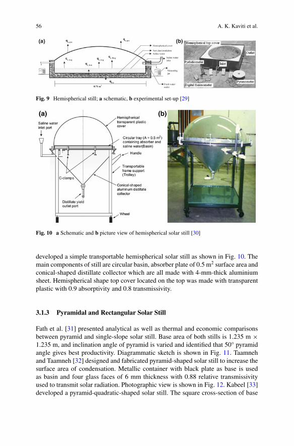
56 A. K. Kaviti et al.
Fig. 9 Hemispherical still; a schematic, b experimental set-up [29]
Fig. 10 a Schematic and b picture view of hemispherical solar still [30]
developed a simple transportable hemispherical solar still as shown in Fig. 10. Themain components of still are circular basin, absorber plate of 0.5 m2 surface area andconical-shaped distillate collector which are all made with 4-mm-thick aluminiumsheet. Hemispherical shape top cover located on the top was made with transparentplastic with 0.9 absorptivity and 0.8 transmissivity.
3.1.3 Pyramidal and Rectangular Solar Still
Fath et al. [31] presented analytical as well as thermal and economic comparisonsbetween pyramid and single-slope solar still. Base area of both stills is 1.235 m ×1.235 m, and inclination angle of pyramid is varied and identified that 50° pyramidangle gives best productivity. Diagrammatic sketch is shown in Fig. 11. Taamnehand Taamneh [32] designed and fabricated pyramid-shaped solar still to increase thesurface area of condensation. Metallic container with black plate as base is usedas basin and four glass faces of 6 mm thickness with 0.88 relative transmissivityused to transmit solar radiation. Photographic view is shown in Fig. 12. Kabeel [33]developed a pyramid-quadratic-shaped solar still. The square cross-section of base
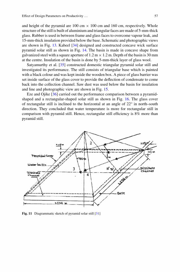
Effect of Design Parameters on Productivity … 57
and height of the pyramid are 100 cm × 100 cm and 160 cm, respectively. Wholestructure of the still is built of aluminium and triangular faces aremade of 5-mm-thickglass. Rubber is used in between frame and glass faces to overcome vapour leak, and15-mm-thick insulation provided below the base. Schematic and photographic viewsare shown in Fig. 13. Kabeel [34] designed and constructed concave wick surfacepyramid solar still as shown in Fig. 14. The basin is made in concave shape fromgalvanized steel with a square aperture of 1.2 m× 1.2 m. Depth of the basin is 30mmat the centre. Insulation of the basin is done by 5-mm-thick layer of glass wool.
Satyamurthy et al. [35] constructed domestic triangular pyramid solar still andinvestigated its performance. The still consists of triangular base which is paintedwith a black colour and was kept inside the wooden box. A piece of glass barrier wasset inside surface of the glass cover to provide the deflection of condensate to comeback into the collection channel. Saw dust was used below the basin for insulationand line and photographic view are shown in Fig. 15.
Eze and Ojike [36] carried out the performance comparison between a pyramid-shaped and a rectangular-shaped solar still as shown in Fig. 16. The glass coverof rectangular still is inclined to the horizontal at an angle of 22° in north–southdirection. They concluded that water temperature is more for rectangular still incomparison with pyramid still. Hence, rectangular still efficiency is 8% more thanpyramid still.
Fig. 11 Diagrammatic sketch of pyramid solar still [31]
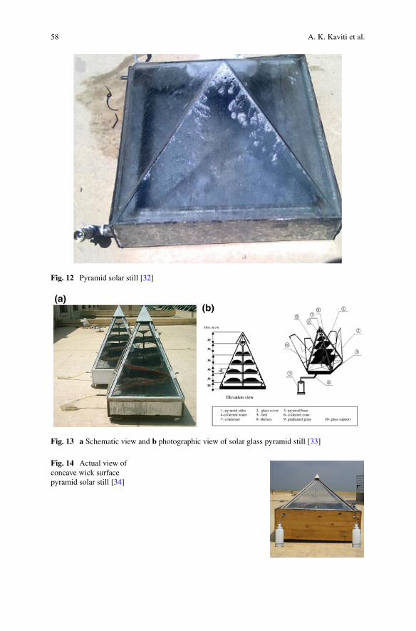
58 A. K. Kaviti et al.
Fig. 12 Pyramid solar still [32]
Fig. 13 a Schematic view and b photographic view of solar glass pyramid still [33]
Fig. 14 Actual view ofconcave wick surfacepyramid solar still [34]
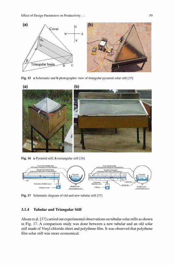
Effect of Design Parameters on Productivity … 59
Fig. 15 a Schematic and b photographic view of triangular pyramid solar still [35]
Fig. 16 a Pyramid still, b rectangular still [36]
Fig. 17 Schematic diagram of old and new tubular still [37]
3.1.4 Tubular and Triangular Still
Ahsan et al. [37] carried out experimental observations on tubular solar stills as shownin Fig. 17. A comparison study was done between a new tubular and an old solarstill made of Vinyl chloride sheet and polythene film. It was observed that polythenefilm solar still was more economical.
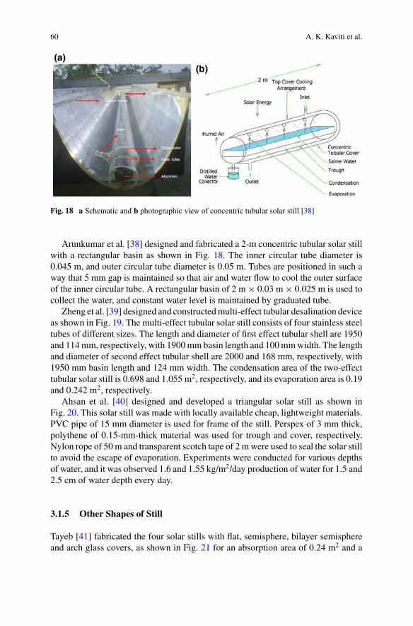
60 A. K. Kaviti et al.
Fig. 18 a Schematic and b photographic view of concentric tubular solar still [38]
Arunkumar et al. [38] designed and fabricated a 2-m concentric tubular solar stillwith a rectangular basin as shown in Fig. 18. The inner circular tube diameter is0.045 m, and outer circular tube diameter is 0.05 m. Tubes are positioned in such away that 5 mm gap is maintained so that air and water flow to cool the outer surfaceof the inner circular tube. A rectangular basin of 2 m× 0.03 m× 0.025 m is used tocollect the water, and constant water level is maintained by graduated tube.
Zheng et al. [39] designed and constructedmulti-effect tubular desalination deviceas shown in Fig. 19. The multi-effect tubular solar still consists of four stainless steeltubes of different sizes. The length and diameter of first effect tubular shell are 1950and 114mm, respectively, with 1900mm basin length and 100mmwidth. The lengthand diameter of second effect tubular shell are 2000 and 168 mm, respectively, with1950 mm basin length and 124 mm width. The condensation area of the two-effecttubular solar still is 0.698 and 1.055 m2, respectively, and its evaporation area is 0.19and 0.242 m2, respectively.
Ahsan et al. [40] designed and developed a triangular solar still as shown inFig. 20. This solar still was made with locally available cheap, lightweight materials.PVC pipe of 15 mm diameter is used for frame of the still. Perspex of 3 mm thick,polythene of 0.15-mm-thick material was used for trough and cover, respectively.Nylon rope of 50 m and transparent scotch tape of 2 mwere used to seal the solar stillto avoid the escape of evaporation. Experiments were conducted for various depthsof water, and it was observed 1.6 and 1.55 kg/m2/day production of water for 1.5 and2.5 cm of water depth every day.
3.1.5 Other Shapes of Still
Tayeb [41] fabricated the four solar stills with flat, semisphere, bilayer semisphereand arch glass covers, as shown in Fig. 21 for an absorption area of 0.24 m2 and a
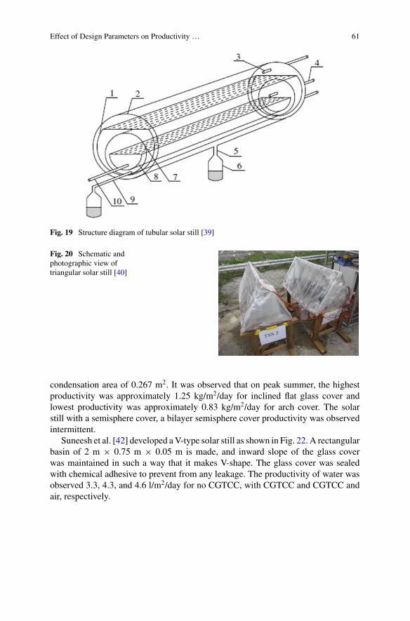
Effect of Design Parameters on Productivity … 61
Fig. 19 Structure diagram of tubular solar still [39]
Fig. 20 Schematic andphotographic view oftriangular solar still [40]
condensation area of 0.267 m2. It was observed that on peak summer, the highestproductivity was approximately 1.25 kg/m2/day for inclined flat glass cover andlowest productivity was approximately 0.83 kg/m2/day for arch cover. The solarstill with a semisphere cover, a bilayer semisphere cover productivity was observedintermittent.
Suneesh et al. [42] developed aV-type solar still as shown in Fig. 22. A rectangularbasin of 2 m × 0.75 m × 0.05 m is made, and inward slope of the glass coverwas maintained in such a way that it makes V-shape. The glass cover was sealedwith chemical adhesive to prevent from any leakage. The productivity of water wasobserved 3.3, 4.3, and 4.6 l/m2/day for no CGTCC, with CGTCC and CGTCC andair, respectively.
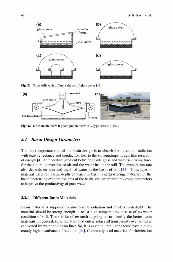
62 A. K. Kaviti et al.
Fig. 21 Solar stills with different shapes of glass cover [41]
Fig. 22 a Schematic view, b photographic view of V-type solar still [42]
3.2 Basin Design Parameters
The most important role of the basin design is to absorb the maximum radiationwith least reflectance and conduction loss to the surroundings. It acts like reservoirof energy [4]. Temperature gradient between inside glass and water is driving forcefor the natural convection of air and the water inside the still. The evaporation ratealso depends on area and depth of water in the basin of still [43]. Thus, type ofmaterial used for basin, depth of water in basin, energy-storing materials in thebasin, increasing evaporation area of the basin, etc. are important design parametersto improve the productivity of pure water.
3.2.1 Different Basin Materials
Basin material is supposed to absorb solar radiation and must be watertight. Thematerial should be strong enough to resist high temperatures in case of no watercondition of still. There is lot of research is going on to identify the better basinmaterials. In general, solar radiation first enters solar still transparent cover which iscaptivated by water and basin liner. So, it is essential that liner should have a mod-erately high absorbance of radiation [44]. Commonly used materials for fabrication
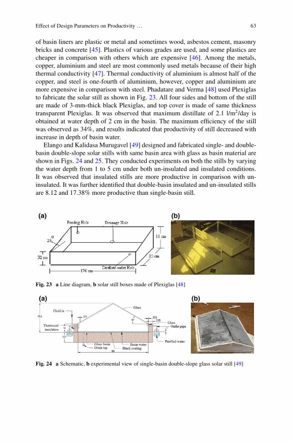
Effect of Design Parameters on Productivity … 63
of basin liners are plastic or metal and sometimes wood, asbestos cement, masonrybricks and concrete [45]. Plastics of various grades are used, and some plastics arecheaper in comparison with others which are expensive [46]. Among the metals,copper, aluminium and steel are most commonly used metals because of their highthermal conductivity [47]. Thermal conductivity of aluminium is almost half of thecopper, and steel is one-fourth of aluminium, however, copper and aluminium aremore expensive in comparison with steel. Phadatare and Verma [48] used Plexiglasto fabricate the solar still as shown in Fig. 23. All four sides and bottom of the stillare made of 3-mm-thick black Plexiglas, and top cover is made of same thicknesstransparent Plexiglas. It was observed that maximum distillate of 2.1 l/m2/day isobtained at water depth of 2 cm in the basin. The maximum efficiency of the stillwas observed as 34%, and results indicated that productivity of still decreased withincrease in depth of basin water.
Elango and Kalidasa Murugavel [49] designed and fabricated single- and double-basin double-slope solar stills with same basin area with glass as basin material areshown in Figs. 24 and 25. They conducted experiments on both the stills by varyingthe water depth from 1 to 5 cm under both un-insulated and insulated conditions.It was observed that insulated stills are more productive in comparison with un-insulated. It was further identified that double-basin insulated and un-insulated stillsare 8.12 and 17.38% more productive than single-basin still.
Fig. 23 a Line diagram, b solar still boxes made of Plexiglas [48]
Fig. 24 a Schematic, b experimental view of single-basin double-slope glass solar still [49]
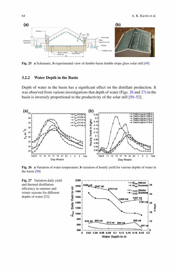
64 A. K. Kaviti et al.
Fig. 25 a Schematic, b experimental view of double-basin double-slope glass solar still [49]
3.2.2 Water Depth in the Basin
Depth of water in the basin has a significant effect on the distillate production. Itwas observed from various investigations that depth of water (Figs. 26 and 27) in thebasin is inversely proportional to the productivity of the solar still [50–52].
Fig. 26 a Variation of water temperature, b variation of hourly yield for various depths of water inthe basin [50]
Fig. 27 Variation daily yieldand thermal distillationefficiency in summer andwinter seasons for differentdepths of water [52]
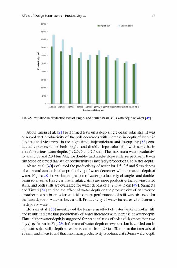
Effect of Design Parameters on Productivity … 65
Fig. 28 Variation in production rate of single- and double-basin stills with depth of water [49]
Aboul Enein et al. [21] performed tests on a deep single-basin solar still. It wasobserved that productivity of the still decreases with increase in depth of water indaytime and vice versa in the night time. Rajmanickam and Ragupathy [53] con-ducted experiments on both single- and double-slope solar stills with same basinarea for various water depths (1, 2.5, 5 and 7.5 cm). The maximum water productiv-ity was 3.07 and 2.34 l/m2/day for double- and single-slope stills, respectively. It wasfurthered observed that water productivity is inversely proportional to water depth.
Ahsan et al. [40] evaluated the productivity of water for 1.5, 2.5 and 5 cm depthsof water and concluded that productivity of water decreases with increase in depth ofwater. Figure 28 shows the comparison of water productivity of single- and double-basin solar stills. It is clear that insulated stills are more productive than un-insulatedstills, and both stills are evaluated for water depths of 1, 2, 3, 4, 5 cm [49]. Sangeetaand Tiwari [54] studied the effect of water depth on the productivity of an invertedabsorber double-basin solar still. Maximum performance of still was observed forthe least depth of water in lowest still. Productivity of water increases with decreasein depth of water.
Hossein et al. [55] investigated the long-term effect of water depth on solar still,and results indicate that productivity of water increases with increase of water depth.Thus, higher water depth is suggested for practical uses of solar stills (more than twodays) as shown in Fig. 29. Influence of water depth on evaporation is carried out ina plastic solar still. Depth of water is varied from 20 to 120 mm in the intervals of20mm, and itwas found thatmaximumproductivity is obtained at 20-mmwater depth
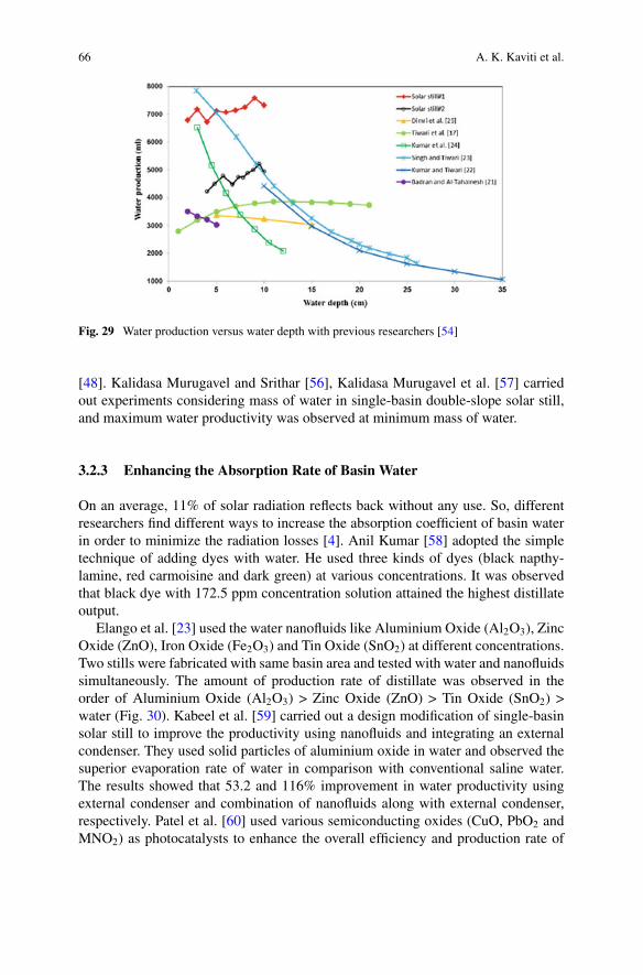
66 A. K. Kaviti et al.
Fig. 29 Water production versus water depth with previous researchers [54]
[48]. Kalidasa Murugavel and Srithar [56], Kalidasa Murugavel et al. [57] carriedout experiments considering mass of water in single-basin double-slope solar still,and maximum water productivity was observed at minimum mass of water.
3.2.3 Enhancing the Absorption Rate of Basin Water
On an average, 11% of solar radiation reflects back without any use. So, differentresearchers find different ways to increase the absorption coefficient of basin waterin order to minimize the radiation losses [4]. Anil Kumar [58] adopted the simpletechnique of adding dyes with water. He used three kinds of dyes (black napthy-lamine, red carmoisine and dark green) at various concentrations. It was observedthat black dye with 172.5 ppm concentration solution attained the highest distillateoutput.
Elango et al. [23] used the water nanofluids like Aluminium Oxide (Al2O3), ZincOxide (ZnO), Iron Oxide (Fe2O3) and Tin Oxide (SnO2) at different concentrations.Two stills were fabricated with same basin area and tested with water and nanofluidssimultaneously. The amount of production rate of distillate was observed in theorder of Aluminium Oxide (Al2O3) > Zinc Oxide (ZnO) > Tin Oxide (SnO2) >water (Fig. 30). Kabeel et al. [59] carried out a design modification of single-basinsolar still to improve the productivity using nanofluids and integrating an externalcondenser. They used solid particles of aluminium oxide in water and observed thesuperior evaporation rate of water in comparison with conventional saline water.The results showed that 53.2 and 116% improvement in water productivity usingexternal condenser and combination of nanofluids along with external condenser,respectively. Patel et al. [60] used various semiconducting oxides (CuO, PbO2 andMNO2) as photocatalysts to enhance the overall efficiency and production rate of
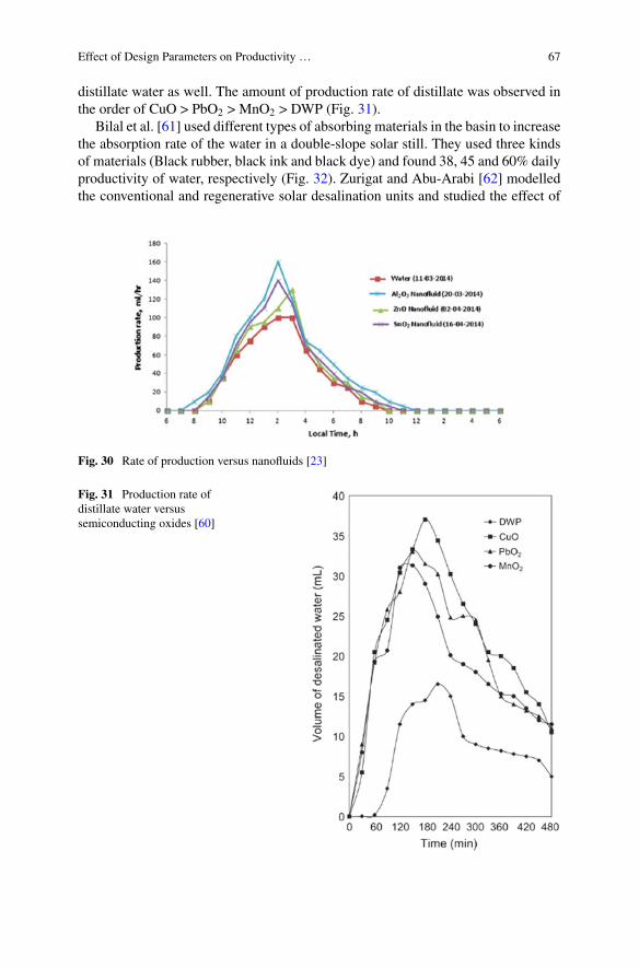
Effect of Design Parameters on Productivity … 67
distillate water as well. The amount of production rate of distillate was observed inthe order of CuO > PbO2 > MnO2 > DWP (Fig. 31).
Bilal et al. [61] used different types of absorbing materials in the basin to increasethe absorption rate of the water in a double-slope solar still. They used three kindsof materials (Black rubber, black ink and black dye) and found 38, 45 and 60% dailyproductivity of water, respectively (Fig. 32). Zurigat and Abu-Arabi [62] modelledthe conventional and regenerative solar desalination units and studied the effect of
Fig. 30 Rate of production versus nanofluids [23]
Fig. 31 Production rate ofdistillate water versussemiconducting oxides [60]
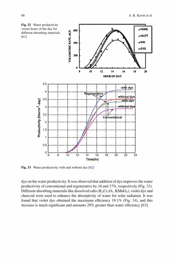
68 A. K. Kaviti et al.
Fig. 32 Water productivityversus hours of the day fordifferent absorbing materials[61]
Fig. 33 Water productivity with and without dye [62]
dye on thewater productivity. It was observed that addition of dye improves the waterproductivity of conventional and regenerative by 16 and 17%, respectively (Fig. 33).Different absorbingmaterials like dissolved salts (K2Cr2O7, KMnO4), violet dye andcharcoal were used to enhance the absorptivity of water for solar radiation. It wasfound that violet dye obtained the maximum efficiency 19.1% (Fig. 34), and thisincrease is much significant and amounts 29% greater than water efficiency [63].
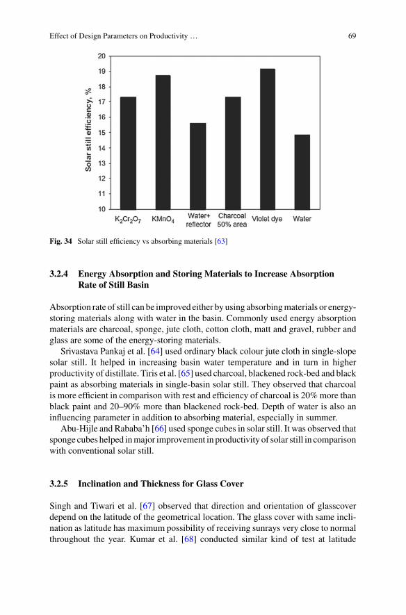
Effect of Design Parameters on Productivity … 69
Fig. 34 Solar still efficiency vs absorbing materials [63]
3.2.4 Energy Absorption and Storing Materials to Increase AbsorptionRate of Still Basin
Absorption rate of still can be improved either by using absorbingmaterials or energy-storing materials along with water in the basin. Commonly used energy absorptionmaterials are charcoal, sponge, jute cloth, cotton cloth, matt and gravel, rubber andglass are some of the energy-storing materials.
Srivastava Pankaj et al. [64] used ordinary black colour jute cloth in single-slopesolar still. It helped in increasing basin water temperature and in turn in higherproductivity of distillate. Tiris et al. [65] used charcoal, blackened rock-bed and blackpaint as absorbing materials in single-basin solar still. They observed that charcoalis more efficient in comparison with rest and efficiency of charcoal is 20%more thanblack paint and 20–90% more than blackened rock-bed. Depth of water is also aninfluencing parameter in addition to absorbing material, especially in summer.
Abu-Hijle and Rababa’h [66] used sponge cubes in solar still. It was observed thatsponge cubes helped inmajor improvement in productivity of solar still in comparisonwith conventional solar still.
3.2.5 Inclination and Thickness for Glass Cover
Singh and Tiwari et al. [67] observed that direction and orientation of glasscoverdepend on the latitude of the geometrical location. The glass cover with same incli-nation as latitude has maximum possibility of receiving sunrays very close to normalthroughout the year. Kumar et al. [68] conducted similar kind of test at latitude
70 A. K. Kaviti et al.
28.36°N by varying the inclination of glass cover and observed that 30° inclinationproduced highest yielding. Akash et al. [69] performed experiments by tilting theglass cover above and below latitude 31.57°N. They observed that tilting angle sameas latitude was 63% more efficient in comparison with other inclinations. Optimumthickness of glass cover helps in enhancing the heat transfer rate. Mink et al. [70]conducted experiments by varying the thickness of glass cover in single-slope solarstill. It was observed that productivity of 3-mm-thick glass cover was 16.5% morethan 6-mm-thick glass cover.
3.2.6 Insulation
The thickness of the insulation also plays a role in reducing heat loss through bot-tom and side walls. Farid and Hamad [20] performed experiments on a single-basindouble-slope solar still with mild steel plate. The basin is lined with concrete, toreduce the heat loss through the bottom surface. Al-Karaghouli and Alnaser con-ducted experiments on solar still with and without insulation of the basin. Dailyproductivity of distillate was 2.46, 2.84 kg/m2, respectively, for without and withinsulation in the month of June.
4 Conclusions
Various designs of solar stills are reviewed with special focus on different shapesof top glass cover and basin design parameters. It is evident from researchers’ workthat there is no clear-cut possibility to optimize the design as yielding of differentsolar stills is different. However, this study will pave a path to researchers to comeup with new optimum designs which can have better performance.
It is also observed that surface of the solar collector is vital in enhancing theproductivity of the solar still. This is where different designs of top glass cover helpfor absorbing the maximum possible radiation.
It is also observed that basin material, depth of water and energy-absorbing mate-rial, inclination of glass cover plate and insulation play an important role in enhanc-ing the performance of the solar still. None of the researchers considered all theinfluencing parameters to study the performance. Hence, there is a lot of scope forimprovement in performance of the solar stills in near future.
References
1. Tiwari GN, Singh HN, Tripathi R (2003) Present status of solar distillation. Solar Energy367–373
Effect of Design Parameters on Productivity … 71
2. Sampathkumar K, Arjuna TV, Pitchandi P, SenthilKumar P (2010) Active solar distillation—adetailed review. Renew Sustain Energy Rev 14:1503–1526
3. Muthu Manokar A, Kalidas Murugavel K, Esakkimuthu G (2014) Different parameters affect-ing the rate of evaporation and condensation on passive solar still—a review. Renew SustainEnergy Rev 38:309–322
4. Malik MAS, Tiwar GN, Kumar A, Sodha MS (1982) Solar distillation. Pergamon Press, UK5. Arjunan TV, Aybar HS, Nedunchezhian N (2009) Status of solar desalination in India. Renew
Sustain Energy Rev 13:2408–24186. Cooper PI (1969) The absorption of radiation in solar stills. Sol Energy 12:3337. Safwat Nafey A, Abdelkader M, Abdelmotalip A, Mabrouk AA (2000) Parameters affecting
solar still productivity. Energy Convers Manag 42:1797–18098. Badran OO (2007) Experimental study of the enhancement parameters on a single slope solar
still productivity. Desalination 209:136–1439. Samee MA, Mirza UK, Majeed T, Ahmad N (2007) Design and performance of a simple and
single basin solar still. Renew Sustain Energy Rev 11:543–54910. Kalidasa Murugavel K, Chockalingam KKSK, Srithar K (2008) Progresses in improving the
effectiveness of the single basin passive solar still. Desalination 220:677–68611. Velmurugana V, Srithar K (2011) Performance analysis of solar stills based on various factors
affecting the productivity—a review. Renew Sustain Energy Rev 15:1294–130412. Kabeel AE, El-Agouz SA (2011) Review of researches and developments on solar stills. Desali-
nation 276:1–1213. Kaushal A, Varun (2010) Solar stills: a review. Renew Sustain Energy Rev 14:446–45314. Gang Xiao, Xihui Wang, Mingjiang Ni, Fei Wang, Weijun Zhu, Zhongyang Luo et al (2013)
A review on solar stills for brine desalination. Appl Energy 103:642–66515. Sivakumar V, Ganapathy Sundaram E (2013) Improvement techniques of solar still efficiency:
a review. Renew Sustain Energy Rev 28:246–26416. Muftah AF, Alghoul MA, Fudholi A, Abdul-Majeed MM, Sopian K (2014) Factors affecting
basin type solar still productivity: a detailed review. Renew Sustain Energy Rev 32:430–44717. Yadav S, Sudhakar K (2015) Different domestic design designs of solar stills: a review. Renew
Sustain Energy Rev 47:718–73118. Tiwari GN,Mukherjee K, Ashok KR, Yadav YP (1986) Comparison of various designs of solar
stills. Desalination 60:191–20219. Cooper PI (1973) The maximum efficiency of single-effect solar stills. Sol Energy 15:205–21720. Farid M, Hamad F (1993) Performance of a single-basin solar still. Renew Energy 3:75–8321. Aboul-Enein S, El-Sebaii AA, El-Bialy E (1998) Investigation of a single-basin solar still with
deep basins. Renew Energy 14:299–30522. Sahoo BB, Sahoo N,Mahanta P, Borbora L, Kalita P, Saha UK (2008) Performance assessment
of a solar still using blackened surface and thermocol insulation. Renew Energy 33:1703–170823. Elango T, Kannan A, Kalidasa Murugavel K (2015) Performance study on single basin single
slope solar still with different water nanofluids. Desalination 360:45–5124. Rubio E, Fernandez JL, Porta MA (2004) Modeling thermal asymmetries in double slope solar
stills. Renew Energy 29:895–90625. Zeroual M, Bouguettaia H, Bechki D, Boughali S, Bouchekima B, Mahcene H (2011) Experi-
mental investigation on a double-slope solar still with partially cooled condenser in the regionof Ouargla (Algeria). Energy Procedia 6:736–742
26. Kalidasa Murugavel K, Chockalingam Kn KSK, Srithar K (2008) An experimental study onsingle basin double slope simulation solar still with thin layer of water in the basin. Desalination220:687–693
27. Bechki D, Bouguettaia H, Blanco-Galvez J, Babay S, Bouchekima B, Boughali S et al (2010)Effect of partial intermittent shading on the performance of a simple basin solar still in southAlgeria. Desalination 260:65–69
28. Dhiman NK (1988) Transient analysis of spherical solar still. Desalination 69:47–5529. Arun Kumar T, Jayaprakash R, Denkenberger D, Ahsan A, Okundamiya MS, Kumar S,
Tanaka H, Aybar HS (2012) An experimental study on a hemispherical solar still. Desalination286:342–348
72 A. K. Kaviti et al.
30. Ismail Basel I (2009) Design and performance of a transportable hemispherical solar still.Renew Energy 34:145–150
31. Fath HES, Samanoudy MEI, Fahmy K, Hassabou A (2003) Thermal-economic analysis andcomparison between pyramid shaped and single slope solar still configurations. Desalination159:69–79
32. Taamneh Y, Taamneh MM (2012) Performance of pyramid-shaped solar still: experimentalstudy. Desalination 291:65–68
33. Kabeel AE (2007) Water production from air using multi-shelves solar glass pyramid system.Renew Energy 32:157–172
34. Kabeel AE (2009) Performance of solar still with a concave wick evaporation surface. Energy34:1504–1509
35. SathyamurthyR,KennadyHJ,NagarajanPK,AhsanA (2014) factors affecting the performanceof triangular pyramid solar still. Desalination 344:383–390
36. Eze JI, Ojike O (2012) Comparative evaluation of rectangular and pyramid-shaped solar stillsusing saline water. Int J Phys Sci 7(31):5202–5208
37. Ahsan A, Imteaz M, Rahman A, Yusuf B, Fukuhara T (2012) Design, fabrication and perfor-mance analysis of an improved solar still. Desalination 292:105–112
38. Arunkumar T, Jayaprakash R, Ahsan A, Denkenberger D, Okundamiya MS (2013) Effect ofwater and air flowon concentric tubular solarwater desalting system.ApplEnergy 103:109–115
39. ZhengH,ChangZ,ChenZ,XieG,WangH (2013) Experimental investigation and performanceanalysis on a group of multi-effect tubular solar desalination devices. Desalination 311:62–68
40. Ahsan A, Imteaz M, Thomas UA, Azmi M, Rahman A, NikDaud NN (2014) Parametersaffecting the performance of a low cost solar still. Appl Energy 114:924–930
41. Tayeb AM (1992) Performance study of some designs of solar still. Energy Convers Manag33:889–898
42. Suneesh PU, Jayaprakash R, Arunkumar T, Denkeberger D (2014) Effect of air flow on V typesolar still with cotton gauze cooling. Desalination 337:1–5
43. Kwatra HS (1996) Performance of a solar still: predicted effect of enhanced evaporation areaon yield and evaporation temperature. Sol Energy 56:261–266
44. Duffie JA (1962) New materials in solar energy utilization. Sol Energy 6:114–11845. Cooper PI, Read WRW (1974) Design philosophy and operating experience Australian stills.
Sol Energy 16:1–846. KohlM, JorgensenG,Brunold S, CarlssonB,HeckM,MollerK (2005)Durability of polymeric
materials. Sol Energy 79:618–62347. Martin CL, Goswami DY (2005) Solar energy pocket reference. International Solar Energy
Society, Freiburg48. Phadatare MK, Verma SK (2007) Influence of water depth on internal heat and mass transfer
in a plastic solar still. Desalination 217:267–27549. Elango T, Kalidasa Murugavel K (2015) The effect of the water depth on the productivity for
single and double basin double slope glass solar stills. Desalination 359:82–9150. Tiwari AK, Tiwari GN (2006) Effect of water depths on heat and mass transfer in a passive
solar still: in summer climatic condition. Desalination 195:78–9451. Tripathi R, Tiwari GN (2006) Thermal modeling of passive and active solar stills for different
depths of water by using the concept of solar fraction. Sol Energy 80:956–96752. Tiwari AK, Tiwari GN (2007) Thermal modeling based on solar fraction and experimental
study of the annual and seasonal performance of a single slope passive solar still: the effect ofwater depths. Desalination 207:184–204
53. Rajamanickam MR, Ragupathy A (2012) Influence of water depth on internal heat and masstransfer in a double slope solar still. Energy Proc 14:1701–1708
54. Sangeeta S, Tiwari GN (1999) Effect of water depth on the performance of an inverted absorberdouble basin solar still. Energy Convers Manag 40:1885–1897
55. Hossein T, Hamed T, Jafarpur K, Estahbanati MRK, Feilizadeh M, Feilizadeh M, ArdekaniAS (2014) A thorough investigation of the effects of water depth on the performance of activesolar stills. Desalination 347:77–85
Effect of Design Parameters on Productivity … 73
56. Kalidasa Murugavel K, Srithar K (2011) Performance study on basin type double slope solarstill with different wick materials and minimum mass of water. Renew Energy 36:612–620
57. Kalidasa Murugavel K, Sivakumar S, Riaz Ahamed J, Chockalingam KKSK, Srithar K (2010)Single basin double slope solar still with minimum basin depth and energy storing materials.Appl Energy 87:514–523
58. Anil Kumar R (1981) Effect of various dyes on solar distillation. Sol Energy 27:51–6559. Kabeel AE, Omara ZM, Essa FA (2014) Enhancement of modified solar still integrated
with external condenser using nanofluids: an experimental approach. Energy Convers Manag78:493–498
60. Patel SG, Bhatnagar S, Vardia J, Ameta SC (2006) Use of photocatalysts in solar desalination.Desalination 189:287–291
61. Bilal AA, Mousa MS, Omar O, Yaser E (1998) Experimental evaluation of a single-basin solarstill using different absorbing materials. Renew Energy 14(1–4):307–310
62. Zurigat YH, Abu-ArabiMK (2004)Modelling and performance analysis of a regenerative solardesalination unit. Appl Therm Eng 24:1061–1072
63. Nijmeh S, Odeh S, Akash B (2005) Experimental and theoretical study of a single-basin solarstill in Jordan. Int Commun Heat Mass Transf 32:565–572
64. Srivastava Pankaj K, Agrawal SK (2013) Experimental and theoretical analysis of single slopedbasin type solar still consisting of multiple low thermal inertia floating porous absorbers.Desalination 311:198–205
65. Tiris C, Tiris M, Ture E (1996) Improvement of basin type solar still performance: use ofvarious absorber materials and collector integration. In: Proceedings of the WREC
66. Abu-Hijleh BAK, Rababa’h HM (2003) Experimental study of a solar still with sponge cubesin basin. Energy Convers Manag 44:1411–1418
67. SinghHN,TiwariGN (2004)Monthly performance of passive and active solar stills for differentIndian climatic condition. Desalination 168:145–150
68. Kumar S, Tiwari G, Singh H (2000) Annual performance of an active solar distillation system.Desalination 127:79–88
69. Akash B, Mohsen M, Nayfeh W (2000) Experimental study of the basin type solar still underlocal climate conditions. Energy Convers Manag 41:883–890
70. Mink G, Horvath L, Evseev EG, Kudish AI (1998) Design parameters, performance testingand analysis of a double-glazed, air-blown solar still with thermal energy recycle. Sol Energy64:265–277
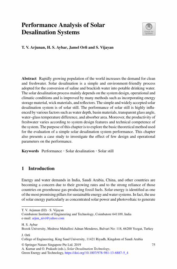
Performance Analysis of SolarDesalination Systems
T. V. Arjunan, H. S. Aybar, Jamel Orfi and S. Vijayan
Abstract Rapidly growing population of the world increases the demand for cleanand freshwater. Solar desalination is a simple and environment-friendly processadopted for the conversion of saline and brackish water into potable drinking water.The solar desalination process mainly depends on the system design, operational andclimatic conditions and is improved by many methods such as incorporating energystoragematerial, wickmaterials, and reflectors. The simple andwidely accepted solardesalination system is of solar still. The performance of solar still is highly influ-enced by various factors such as water depth, basinmaterials, transparent glass angle,water–glass temperature difference, and absorber area. Moreover, the productivity offreshwater varies according to system design features and technical competence ofthe system. The purpose of this chapter is to explore the basic theoreticalmethod usedfor the evaluation of a simple solar desalination system performance. This chapteralso presents a case study to investigate the effect of few design and operationalparameters on the performance.
Keywords Performance · Solar desalination · Solar still
1 Introduction
Energy and water demands in India, Saudi Arabia, China, and other countries arebecoming a concern due to their growing rates and to the strong reliance of thosecountries on greenhouse gas-producing fossil fuels. Solar energy is identified as oneof themost promising pillars for sustainable energy andwater systems. In fact, the useof solar energy particularly as concentrated solar power and photovoltaic to generate
T. V. Arjunan (B) · S. VijayanCoimbatore Institute of Engineering and Technology, Coimbatore 641109, Indiae-mail: [email protected]
H. S. AybarBozok University, Medrese Mahallesi Adnan Menderes, Bulvari No: 118, 66200 Yozgat, Turkey
J. OrfiCollege of Engineering, King Saud University, 11421 Riyadh, Kingdom of Saudi Arabia
© Springer Nature Singapore Pte Ltd. 2019A. Kumar and O. Prakash (eds.), Solar Desalination Technology,Green Energy and Technology, https://doi.org/10.1007/978-981-13-6887-5_4
75
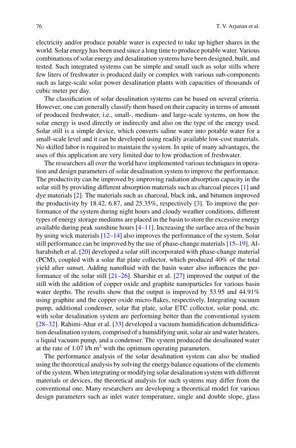
76 T. V. Arjunan et al.
electricity and/or produce potable water is expected to take up higher shares in theworld. Solar energy has been used since a long time to produce potable water. Variouscombinations of solar energy and desalination systems have been designed, built, andtested. Such integrated systems can be simple and small such as solar stills wherefew liters of freshwater is produced daily or complex with various sub-componentssuch as large-scale solar power desalination plants with capacities of thousands ofcubic meter per day.
The classification of solar desalination systems can be based on several criteria.However, one can generally classify them based on their capacity in terms of amountof produced freshwater, i.e., small-, medium- and large-scale systems, on how thesolar energy is used directly or indirectly and also on the type of the energy used.Solar still is a simple device, which converts saline water into potable water for asmall-scale level and it can be developed using readily available low-cost materials.No skilled labor is required to maintain the system. In spite of many advantages, theuses of this application are very limited due to low production of freshwater.
The researchers all over the world have implemented various techniques in opera-tion and design parameters of solar desalination system to improve the performance.The productivity can be improved by improving radiation absorption capacity in thesolar still by providing different absorption materials such as charcoal pieces [1] anddye materials [2]. The materials such as charcoal, black ink, and bitumen improvedthe productivity by 18.42, 6.87, and 25.35%, respectively [3]. To improve the per-formance of the system during night hours and cloudy weather conditions, differenttypes of energy storage mediums are placed in the basin to store the excessive energyavailable during peak sunshine hours [4–11]. Increasing the surface area of the basinby using wick materials [12–14] also improves the performance of the system. Solarstill performance can be improved by the use of phase-change materials [15–19]. Al-harahsheh et al. [20] developed a solar still incorporated with phase-change material(PCM), coupled with a solar flat plate collector, which produced 40% of the totalyield after sunset. Adding nanofluid with the basin water also influences the per-formance of the solar still [21–26]. Sharshir et al. [27] improved the output of thestill with the addition of copper oxide and graphite nanoparticles for various basinwater depths. The results show that the output is improved by 53.95 and 44.91%using graphite and the copper oxide micro-flakes, respectively. Integrating vacuumpump, additional condenser, solar flat plate, solar ETC collector, solar pond, etc.with solar desalination system are performing better than the conventional system[28–32]. Rahimi-Ahar et al. [33] developed a vacuum humidification dehumidifica-tion desalination system, comprised of a humidifying unit, solar air andwater heaters,a liquid vacuum pump, and a condenser. The system produced the desalinated waterat the rate of 1.07 l/h m2 with the optimum operating parameters.
The performance analysis of the solar desalination system can also be studiedusing the theoretical analysis by solving the energy balance equations of the elementsof the system.When integrating ormodifying solar desalination systemwith differentmaterials or devices, the theoretical analysis for such systems may differ from theconventional one. Many researchers are developing a theoretical model for variousdesign parameters such as inlet water temperature, single and double slope, glass
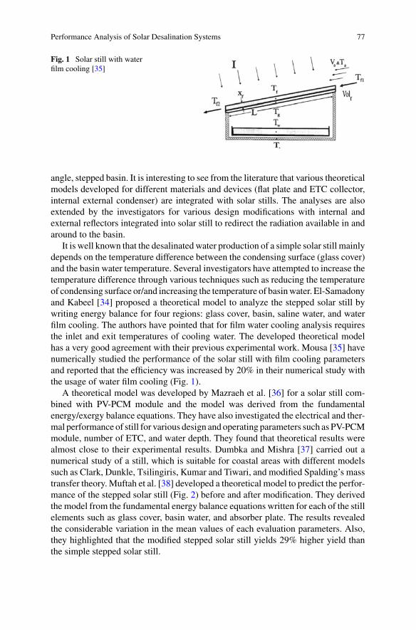
Performance Analysis of Solar Desalination Systems 77
Fig. 1 Solar still with waterfilm cooling [35]
angle, stepped basin. It is interesting to see from the literature that various theoreticalmodels developed for different materials and devices (flat plate and ETC collector,internal external condenser) are integrated with solar stills. The analyses are alsoextended by the investigators for various design modifications with internal andexternal reflectors integrated into solar still to redirect the radiation available in andaround to the basin.
It is well known that the desalinated water production of a simple solar still mainlydepends on the temperature difference between the condensing surface (glass cover)and the basin water temperature. Several investigators have attempted to increase thetemperature difference through various techniques such as reducing the temperatureof condensing surface or/and increasing the temperature of basinwater. El-Samadonyand Kabeel [34] proposed a theoretical model to analyze the stepped solar still bywriting energy balance for four regions: glass cover, basin, saline water, and waterfilm cooling. The authors have pointed that for film water cooling analysis requiresthe inlet and exit temperatures of cooling water. The developed theoretical modelhas a very good agreement with their previous experimental work. Mousa [35] havenumerically studied the performance of the solar still with film cooling parametersand reported that the efficiency was increased by 20% in their numerical study withthe usage of water film cooling (Fig. 1).
A theoretical model was developed by Mazraeh et al. [36] for a solar still com-bined with PV-PCM module and the model was derived from the fundamentalenergy/exergy balance equations. They have also investigated the electrical and ther-mal performance of still for various design and operating parameters such as PV-PCMmodule, number of ETC, and water depth. They found that theoretical results werealmost close to their experimental results. Dumbka and Mishra [37] carried out anumerical study of a still, which is suitable for coastal areas with different modelssuch as Clark, Dunkle, Tsilingiris, Kumar and Tiwari, and modified Spalding’s masstransfer theory. Muftah et al. [38] developed a theoretical model to predict the perfor-mance of the stepped solar still (Fig. 2) before and after modification. They derivedthe model from the fundamental energy balance equations written for each of the stillelements such as glass cover, basin water, and absorber plate. The results revealedthe considerable variation in the mean values of each evaluation parameters. Also,they highlighted that the modified stepped solar still yields 29% higher yield thanthe simple stepped solar still.
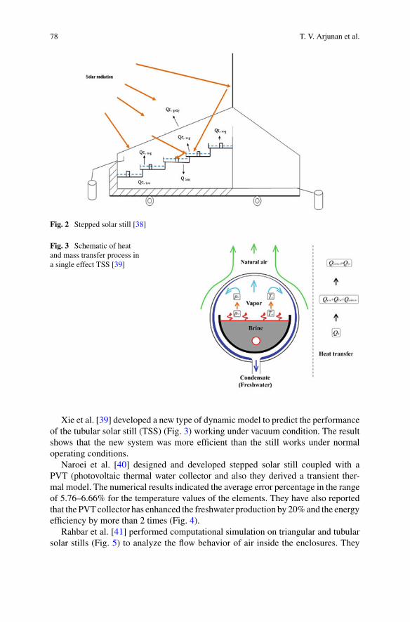
78 T. V. Arjunan et al.
Fig. 2 Stepped solar still [38]
Fig. 3 Schematic of heatand mass transfer process ina single effect TSS [39]
Xie et al. [39] developed a new type of dynamic model to predict the performanceof the tubular solar still (TSS) (Fig. 3) working under vacuum condition. The resultshows that the new system was more efficient than the still works under normaloperating conditions.
Naroei et al. [40] designed and developed stepped solar still coupled with aPVT (photovoltaic thermal water collector and also they derived a transient ther-mal model. The numerical results indicated the average error percentage in the rangeof 5.76–6.66% for the temperature values of the elements. They have also reportedthat the PVT collector has enhanced the freshwater production by 20%and the energyefficiency by more than 2 times (Fig. 4).
Rahbar et al. [41] performed computational simulation on triangular and tubularsolar stills (Fig. 5) to analyze the flow behavior of air inside the enclosures. They
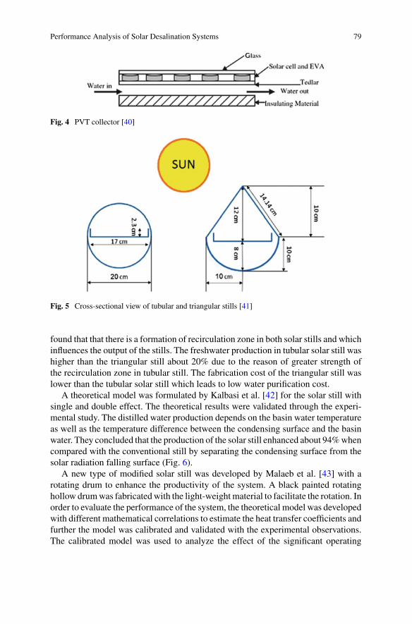
Performance Analysis of Solar Desalination Systems 79
Fig. 4 PVT collector [40]
Fig. 5 Cross-sectional view of tubular and triangular stills [41]
found that that there is a formation of recirculation zone in both solar stills and whichinfluences the output of the stills. The freshwater production in tubular solar still washigher than the triangular still about 20% due to the reason of greater strength ofthe recirculation zone in tubular still. The fabrication cost of the triangular still waslower than the tubular solar still which leads to low water purification cost.
A theoretical model was formulated by Kalbasi et al. [42] for the solar still withsingle and double effect. The theoretical results were validated through the experi-mental study. The distilled water production depends on the basin water temperatureas well as the temperature difference between the condensing surface and the basinwater. They concluded that the production of the solar still enhanced about 94%whencompared with the conventional still by separating the condensing surface from thesolar radiation falling surface (Fig. 6).
A new type of modified solar still was developed by Malaeb et al. [43] with arotating drum to enhance the productivity of the system. A black painted rotatinghollow drumwas fabricatedwith the light-weightmaterial to facilitate the rotation. Inorder to evaluate the performance of the system, the theoretical model was developedwith different mathematical correlations to estimate the heat transfer coefficients andfurther the model was calibrated and validated with the experimental observations.The calibrated model was used to analyze the effect of the significant operating
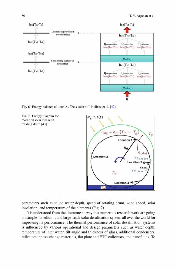
80 T. V. Arjunan et al.
Fig. 6 Energy balance of double effects solar still Kalbasi et al. [42]
Fig. 7 Energy diagram formodified solar still withrotating drum [43]
parameters such as saline water depth, speed of rotating drum, wind speed, solarinsolation, and temperature of the elements (Fig. 7).
It is understood from the literature survey that numerous research work are goingon simple-, medium-, and large-scale solar desalination system all over the world forimproving its performance. The thermal performance of solar desalination systemsis influenced by various operational and design parameters such as water depth,temperature of inlet water, tilt angle and thickness of glass, additional condensers,reflectors, phase-change materials, flat plate and ETC collectors, and nanofluids. To
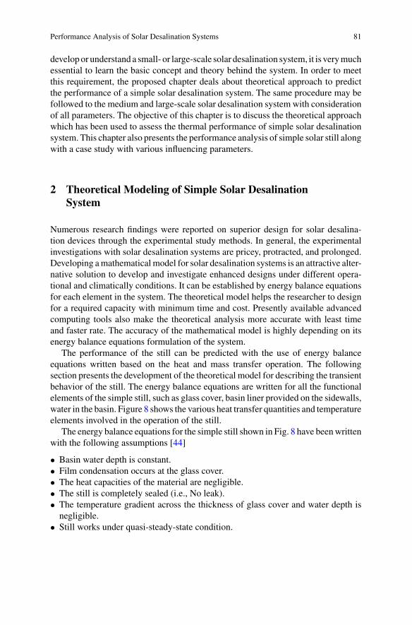
Performance Analysis of Solar Desalination Systems 81
developor understand a small- or large-scale solar desalination system, it is verymuchessential to learn the basic concept and theory behind the system. In order to meetthis requirement, the proposed chapter deals about theoretical approach to predictthe performance of a simple solar desalination system. The same procedure may befollowed to the medium and large-scale solar desalination system with considerationof all parameters. The objective of this chapter is to discuss the theoretical approachwhich has been used to assess the thermal performance of simple solar desalinationsystem. This chapter also presents the performance analysis of simple solar still alongwith a case study with various influencing parameters.
2 Theoretical Modeling of Simple Solar DesalinationSystem
Numerous research findings were reported on superior design for solar desalina-tion devices through the experimental study methods. In general, the experimentalinvestigations with solar desalination systems are pricey, protracted, and prolonged.Developing amathematical model for solar desalination systems is an attractive alter-native solution to develop and investigate enhanced designs under different opera-tional and climatically conditions. It can be established by energy balance equationsfor each element in the system. The theoretical model helps the researcher to designfor a required capacity with minimum time and cost. Presently available advancedcomputing tools also make the theoretical analysis more accurate with least timeand faster rate. The accuracy of the mathematical model is highly depending on itsenergy balance equations formulation of the system.
The performance of the still can be predicted with the use of energy balanceequations written based on the heat and mass transfer operation. The followingsection presents the development of the theoretical model for describing the transientbehavior of the still. The energy balance equations are written for all the functionalelements of the simple still, such as glass cover, basin liner provided on the sidewalls,water in the basin. Figure 8 shows the various heat transfer quantities and temperatureelements involved in the operation of the still.
The energy balance equations for the simple still shown in Fig. 8 have beenwrittenwith the following assumptions [44]
• Basin water depth is constant.• Film condensation occurs at the glass cover.• The heat capacities of the material are negligible.• The still is completely sealed (i.e., No leak).• The temperature gradient across the thickness of glass cover and water depth isnegligible.
• Still works under quasi-steady-state condition.
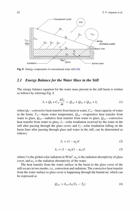
82 T. V. Arjunan et al.
Fig. 8 Energy components of conventional solar still [44]
2.1 Energy Balance for the Water Mass in the Still
The energy balance equation for the water mass present in the still basin is writtenas follows by referring Fig. 8
I1 + Qb + CwdTwdt
� Qcw + Qrw + Qew + I2 (1)
whereQb—convective heat transfer from basin to water,Cw—heat capacity of waterin the basin, Tw—basin water temperature, Qew—evaporative heat transfer fromwater to glass, Qrw—radiative heat transfer from water to glass, Qcw—convectiveheat transfer from water to glass, I1—solar irradiation received by the water in thestill after passing through the glass cover, and I2—solar irradiation falling on thebasin liner after passing through glass and water in the still, can be determined asfollows:
I1 � (1 − αg)I (2)
I2 � (1 − αg)(1 − αw)I (3)
where I is the global solar radiation inW/m2, αg is the radiation absorptivity of glasscover, and αw is the radiation absorptivity of the water.
The heat transfer from the water surface in the basin to the glass cover of thestill occurs in two modes, i.e., convection and radiation. The convective heat transferfrom the water surface to glass cover is happening through the humid air, which canbe expressed as
Qcw � hcwAw(Tw − Tg) (4)
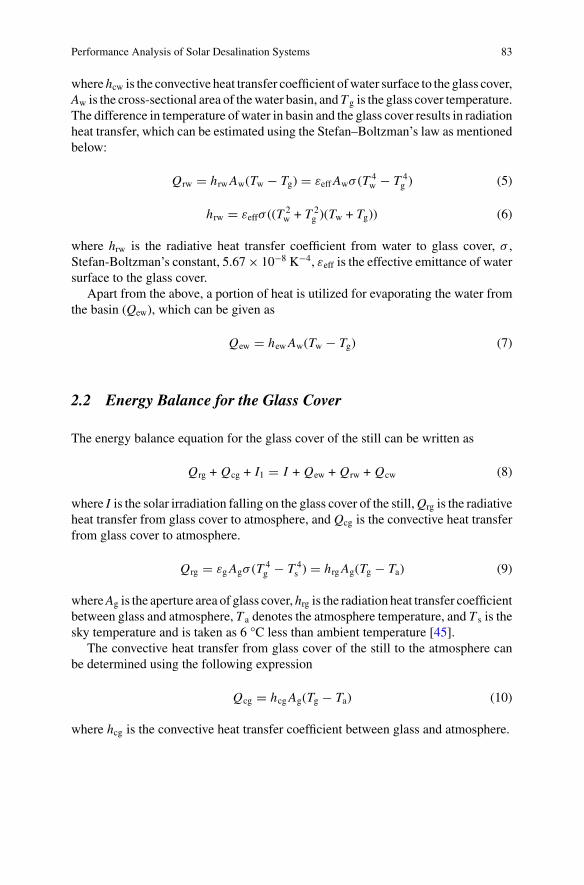
Performance Analysis of Solar Desalination Systems 83
where hcw is the convective heat transfer coefficient ofwater surface to the glass cover,Aw is the cross-sectional area of thewater basin, andT g is the glass cover temperature.The difference in temperature of water in basin and the glass cover results in radiationheat transfer, which can be estimated using the Stefan–Boltzman’s law as mentionedbelow:
Qrw � hrwAw(Tw − Tg) � εeffAwσ (T 4w − T 4
g ) (5)
hrw � εeffσ ((T2w + T 2
g )(Tw + Tg)) (6)
where hrw is the radiative heat transfer coefficient from water to glass cover, σ ,Stefan-Boltzman’s constant, 5.67× 10⁻⁸ K−4, εeff is the effective emittance of watersurface to the glass cover.
Apart from the above, a portion of heat is utilized for evaporating the water fromthe basin (Qew), which can be given as
Qew � hewAw(Tw − Tg) (7)
2.2 Energy Balance for the Glass Cover
The energy balance equation for the glass cover of the still can be written as
Qrg + Qcg + I1 � I + Qew + Qrw + Qcw (8)
where I is the solar irradiation falling on the glass cover of the still,Qrg is the radiativeheat transfer from glass cover to atmosphere, and Qcg is the convective heat transferfrom glass cover to atmosphere.
Qrg � εgAgσ (T4g − T 4
s ) � hrgAg(Tg − Ta) (9)
whereAg is the aperture area of glass cover, hrg is the radiation heat transfer coefficientbetween glass and atmosphere, T a denotes the atmosphere temperature, and T s is thesky temperature and is taken as 6 °C less than ambient temperature [45].
The convective heat transfer from glass cover of the still to the atmosphere canbe determined using the following expression
Qcg � hcgAg(Tg − Ta) (10)
where hcg is the convective heat transfer coefficient between glass and atmosphere.
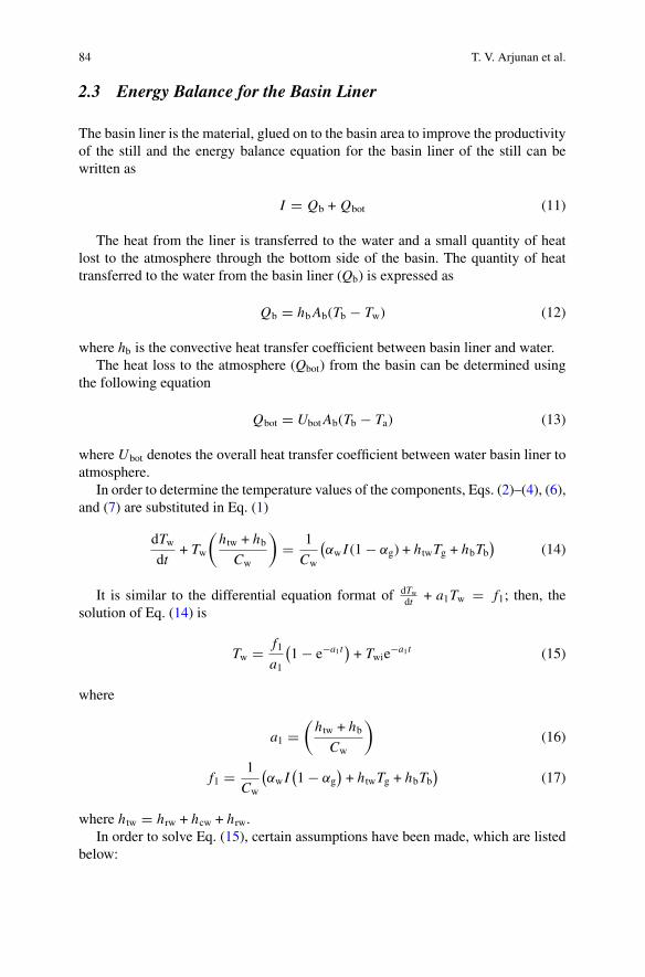
84 T. V. Arjunan et al.
2.3 Energy Balance for the Basin Liner
The basin liner is the material, glued on to the basin area to improve the productivityof the still and the energy balance equation for the basin liner of the still can bewritten as
I � Qb + Qbot (11)
The heat from the liner is transferred to the water and a small quantity of heatlost to the atmosphere through the bottom side of the basin. The quantity of heattransferred to the water from the basin liner (Qb) is expressed as
Qb � hbAb(Tb − Tw) (12)
where hb is the convective heat transfer coefficient between basin liner and water.The heat loss to the atmosphere (Qbot) from the basin can be determined using
the following equation
Qbot � UbotAb(Tb − Ta) (13)
where Ubot denotes the overall heat transfer coefficient between water basin liner toatmosphere.
In order to determine the temperature values of the components, Eqs. (2)–(4), (6),and (7) are substituted in Eq. (1)
dTwdt
+ Tw
(htw + hb
Cw
)� 1
Cw
(αw I (1 − αg) + htwTg + hbTb
)(14)
It is similar to the differential equation format of dTwdt + a1Tw � f1; then, the
solution of Eq. (14) is
Tw � f1a1
(1 − e−a1t
)+ Twie
−a1t (15)
where
a1 �(htw + hb
Cw
)(16)
f1 � 1
Cw
(αw I
(1 − αg
)+ htwTg + hbTb
)(17)
where htw � hrw + hcw + hrw.In order to solve Eq. (15), certain assumptions have been made, which are listed
below:
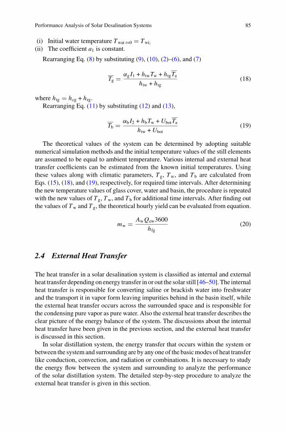
Performance Analysis of Solar Desalination Systems 85
(i) Initial water temperature Twat t=0 � Twi;
(ii) The coefficient a1 is constant.
Rearranging Eq. (8) by substituting (9), (10), (2)–(6), and (7)
Tg � αg I1 + htwTw + htgTahtw + htg
(18)
where htg � hcg + hrg.Rearranging Eq. (11) by substituting (12) and (13),
Tb � αb I2 + hbTw +UbotTahtw +Ubot
(19)
The theoretical values of the system can be determined by adopting suitablenumerical simulation methods and the initial temperature values of the still elementsare assumed to be equal to ambient temperature. Various internal and external heattransfer coefficients can be estimated from the known initial temperatures. Usingthese values along with climatic parameters, T g, Tw, and T b are calculated fromEqs. (15), (18), and (19), respectively, for required time intervals. After determiningthe new temperature values of glass cover, water and basin, the procedure is repeatedwith the new values of T g, Tw, and T b for additional time intervals. After finding outthe values of Tw and T g, the theoretical hourly yield can be evaluated from equation.
mw � AwQew3600
hfg(20)
2.4 External Heat Transfer
The heat transfer in a solar desalination system is classified as internal and externalheat transfer depending on energy transfer in or out the solar still [46–50]. The internalheat transfer is responsible for converting saline or brackish water into freshwaterand the transport it in vapor form leaving impurities behind in the basin itself, whilethe external heat transfer occurs across the surrounded space and is responsible forthe condensing pure vapor as pure water. Also the external heat transfer describes theclear picture of the energy balance of the system. The discussions about the internalheat transfer have been given in the previous section, and the external heat transferis discussed in this section.
In solar distillation system, the energy transfer that occurs within the system orbetween the systemand surrounding are by any one of the basicmodes of heat transferlike conduction, convection, and radiation or combinations. It is necessary to studythe energy flow between the system and surrounding to analyze the performanceof the solar distillation system. The detailed step-by-step procedure to analyze theexternal heat transfer is given in this section.
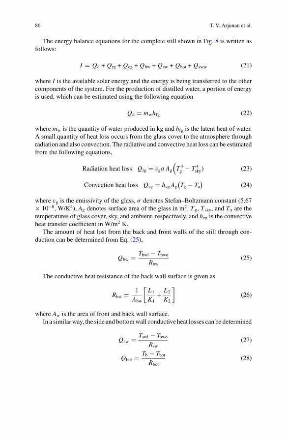
86 T. V. Arjunan et al.
The energy balance equations for the complete still shown in Fig. 8 is written asfollows:
I � Qd + Qrg + Qcg + Qbw + Qsw + Qbot + Qsww (21)
where I is the available solar energy and the energy is being transferred to the othercomponents of the system. For the production of distilled water, a portion of energyis used, which can be estimated using the following equation
Qd � mwhfg (22)
where mw is the quantity of water produced in kg and hfg is the latent heat of water.A small quantity of heat loss occurs from the glass cover to the atmosphere throughradiation and also convection. The radiative and convective heat loss can be estimatedfrom the following equations,
Radiation heat loss Qrg � εgσ Ag
(T 4g − T 4
sky) (23)
Convection heat loss Qcg � hcgAg(Tg − Ta
)(24)
where εg is the emissivity of the glass, σ denotes Stefan–Boltzmann constant (5.67× 10⁻⁸, W/K4), Ag denotes surface area of the glass in m2, T g, T sky, and T a are thetemperatures of glass cover, sky, and ambient, respectively, and hcg is the convectiveheat transfer coefficient in W/m2 K.
The amount of heat lost from the back and front walls of the still through con-duction can be determined from Eq. (25),
Qbw � Tbwi − TbwoRbw
(25)
The conductive heat resistance of the back wall surface is given as
Rbw � 1
Abw
[L1
K1+
L2
K2
](26)
where Aw is the area of front and back wall surface.In a similarway, the side and bottomwall conductive heat losses can be determined
Qsw � Tswi − TswoRsw
(27)
Qbot � Tb − TbotRbot
(28)
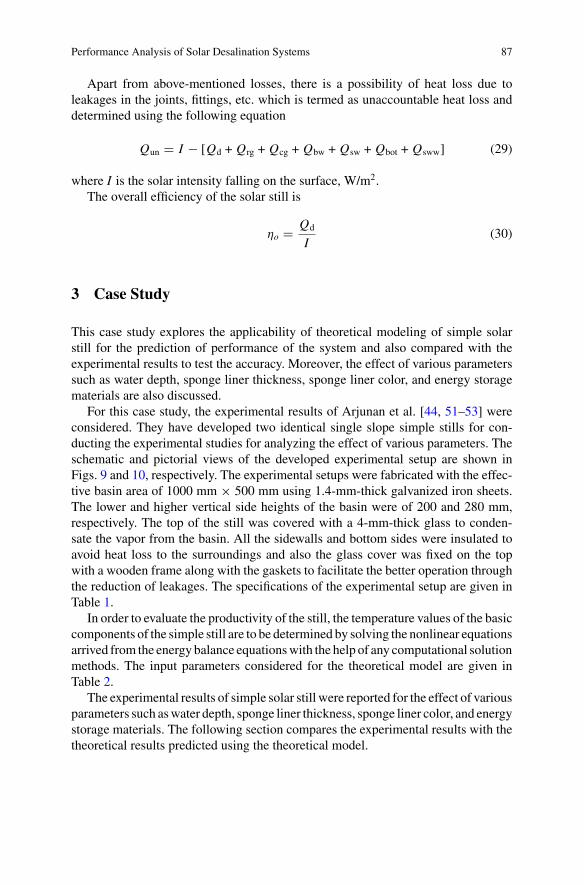
Performance Analysis of Solar Desalination Systems 87
Apart from above-mentioned losses, there is a possibility of heat loss due toleakages in the joints, fittings, etc. which is termed as unaccountable heat loss anddetermined using the following equation
Qun � I − [Qd + Qrg + Qcg + Qbw + Qsw + Qbot + Qsww] (29)
where I is the solar intensity falling on the surface, W/m2.The overall efficiency of the solar still is
ηo � Qd
I(30)
3 Case Study
This case study explores the applicability of theoretical modeling of simple solarstill for the prediction of performance of the system and also compared with theexperimental results to test the accuracy. Moreover, the effect of various parameterssuch as water depth, sponge liner thickness, sponge liner color, and energy storagematerials are also discussed.
For this case study, the experimental results of Arjunan et al. [44, 51–53] wereconsidered. They have developed two identical single slope simple stills for con-ducting the experimental studies for analyzing the effect of various parameters. Theschematic and pictorial views of the developed experimental setup are shown inFigs. 9 and 10, respectively. The experimental setups were fabricated with the effec-tive basin area of 1000 mm × 500 mm using 1.4-mm-thick galvanized iron sheets.The lower and higher vertical side heights of the basin were of 200 and 280 mm,respectively. The top of the still was covered with a 4-mm-thick glass to conden-sate the vapor from the basin. All the sidewalls and bottom sides were insulated toavoid heat loss to the surroundings and also the glass cover was fixed on the topwith a wooden frame along with the gaskets to facilitate the better operation throughthe reduction of leakages. The specifications of the experimental setup are given inTable 1.
In order to evaluate the productivity of the still, the temperature values of the basiccomponents of the simple still are to be determined by solving the nonlinear equationsarrived from the energy balance equationswith the help of any computational solutionmethods. The input parameters considered for the theoretical model are given inTable 2.
The experimental results of simple solar still were reported for the effect of variousparameters such aswater depth, sponge liner thickness, sponge liner color, and energystorage materials. The following section compares the experimental results with thetheoretical results predicted using the theoretical model.
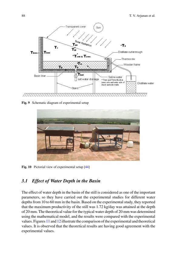
88 T. V. Arjunan et al.
Fig. 9 Schematic diagram of experimental setup
Fig. 10 Pictorial view of experimental setup [44]
3.1 Effect of Water Depth in the Basin
The effect of water depth in the basin of the still is considered as one of the importantparameters, so they have carried out the experimental studies for different waterdepths from 10 to 60mm in the basin. Based on the experimental study, they reportedthat the maximum productivity of the still was 1.72 kg/day was attained at the depthof 20mm. The theoretical value for the typical water depth of 20mmwas determinedusing the mathematical model, and the results were compared with the experimentalvalues. Figures 11 and12 illustrate the comparison of the experimental and theoreticalvalues. It is observed that the theoretical results are having good agreement with theexperimental values.
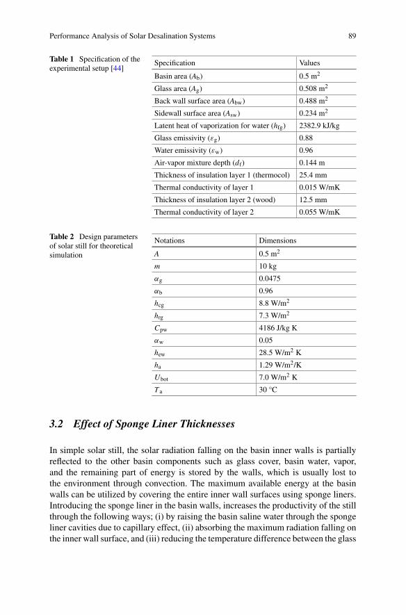
Performance Analysis of Solar Desalination Systems 89
Table 1 Specification of theexperimental setup [44]
Specification Values
Basin area (Ab) 0.5 m2
Glass area (Ag) 0.508 m2
Back wall surface area (Abw) 0.488 m2
Sidewall surface area (Asw) 0.234 m2
Latent heat of vaporization for water (hfg) 2382.9 kJ/kg
Glass emissivity (εg) 0.88
Water emissivity (εw) 0.96
Air-vapor mixture depth (df) 0.144 m
Thickness of insulation layer 1 (thermocol) 25.4 mm
Thermal conductivity of layer 1 0.015 W/mK
Thickness of insulation layer 2 (wood) 12.5 mm
Thermal conductivity of layer 2 0.055 W/mK
Table 2 Design parametersof solar still for theoreticalsimulation
Notations Dimensions
A 0.5 m2
m 10 kg
αg 0.0475
αb 0.96
hcg 8.8 W/m2
hrg 7.3 W/m2
Cpw 4186 J/kg K
αw 0.05
hew 28.5 W/m2 K
ha 1.29 W/m2/K
Ubot 7.0 W/m2 K
T a 30 °C
3.2 Effect of Sponge Liner Thicknesses
In simple solar still, the solar radiation falling on the basin inner walls is partiallyreflected to the other basin components such as glass cover, basin water, vapor,and the remaining part of energy is stored by the walls, which is usually lost tothe environment through convection. The maximum available energy at the basinwalls can be utilized by covering the entire inner wall surfaces using sponge liners.Introducing the sponge liner in the basin walls, increases the productivity of the stillthrough the following ways; (i) by raising the basin saline water through the spongeliner cavities due to capillary effect, (ii) absorbing the maximum radiation falling onthe inner wall surface, and (iii) reducing the temperature difference between the glass
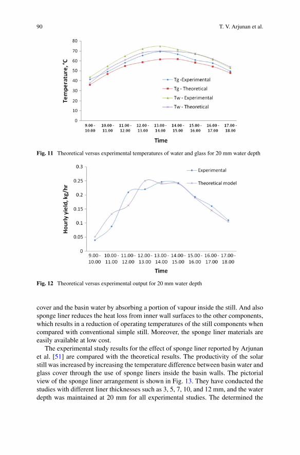
90 T. V. Arjunan et al.
Fig. 11 Theoretical versus experimental temperatures of water and glass for 20 mm water depth
Fig. 12 Theoretical versus experimental output for 20 mm water depth
cover and the basin water by absorbing a portion of vapour inside the still. And alsosponge liner reduces the heat loss from inner wall surfaces to the other components,which results in a reduction of operating temperatures of the still components whencompared with conventional simple still. Moreover, the sponge liner materials areeasily available at low cost.
The experimental study results for the effect of sponge liner reported by Arjunanet al. [51] are compared with the theoretical results. The productivity of the solarstill was increased by increasing the temperature difference between basin water andglass cover through the use of sponge liners inside the basin walls. The pictorialview of the sponge liner arrangement is shown in Fig. 13. They have conducted thestudies with different liner thicknesses such as 3, 5, 7, 10, and 12 mm, and the waterdepth was maintained at 20 mm for all experimental studies. The determined the
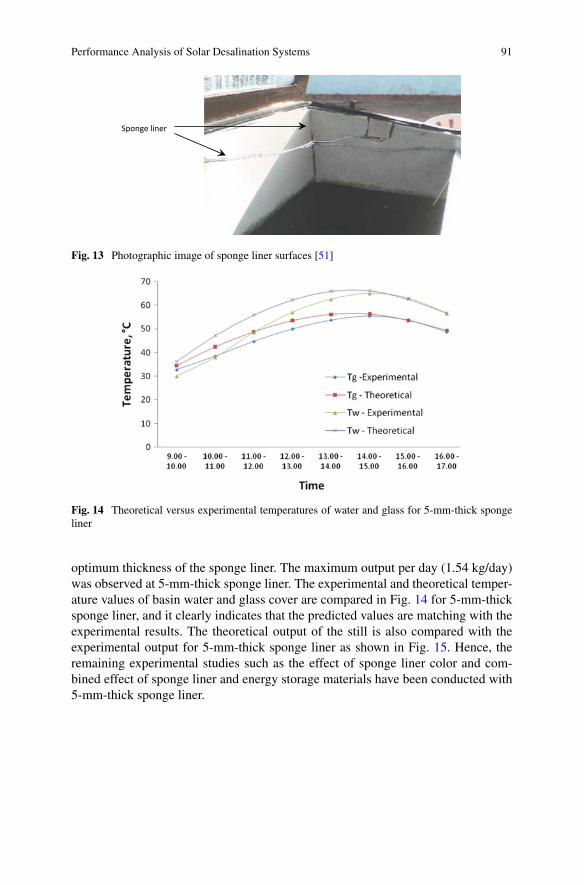
Performance Analysis of Solar Desalination Systems 91
Sponge liner
Fig. 13 Photographic image of sponge liner surfaces [51]
Fig. 14 Theoretical versus experimental temperatures of water and glass for 5-mm-thick spongeliner
optimum thickness of the sponge liner. The maximum output per day (1.54 kg/day)was observed at 5-mm-thick sponge liner. The experimental and theoretical temper-ature values of basin water and glass cover are compared in Fig. 14 for 5-mm-thicksponge liner, and it clearly indicates that the predicted values are matching with theexperimental results. The theoretical output of the still is also compared with theexperimental output for 5-mm-thick sponge liner as shown in Fig. 15. Hence, theremaining experimental studies such as the effect of sponge liner color and com-bined effect of sponge liner and energy storage materials have been conducted with5-mm-thick sponge liner.
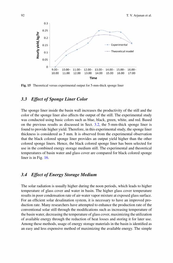
92 T. V. Arjunan et al.
Fig. 15 Theoretical versus experimental output for 5-mm-thick sponge liner
3.3 Effect of Sponge Liner Color
The sponge liner inside the basin wall increases the productivity of the still and thecolor of the sponge liner also affects the output of the still. The experimental studywas conducted using basic colors such as blue, black, green, white, and red. Basedon the previous results as discussed in Sect. 3.2, the 5-mm-thick sponge liner isfound to provide higher yield. Therefore, in this experimental study, the sponge linerthickness is considered as 5 mm. It is observed from the experimental observationthat the black colored sponge liner provides an output yield higher than the othercolored sponge liners. Hence, the black colored sponge liner has been selected foruse in the combined energy storage medium still. The experimental and theoreticaltemperatures of basin water and glass cover are compared for black colored spongeliner is in Fig. 16.
3.4 Effect of Energy Storage Medium
The solar radiation is usually higher during the noon periods, which leads to highertemperature of glass cover and water in basin. The higher glass cover temperatureresults in poor condensation rate of air-water vapor mixture at exposed glass surface.For an efficient solar desalination system, it is necessary to have an improved pro-duction rate. Many researchers have attempted to enhance the production rate of theconventional solar still through the modifications such as increasing temperature ofthe basin water, decreasing the temperature of glass cover, maximizing the utilizationof available energy through the reduction of heat losses and storing it for later use.Among these methods, usage of energy storage materials in the basin is identified asan easy and less expensive method of maximizing the available energy. The simple
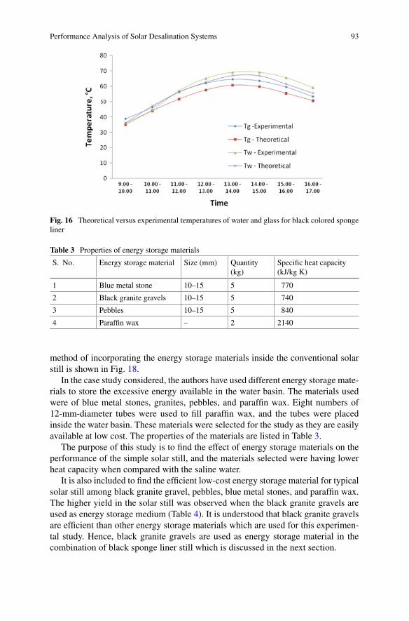
Performance Analysis of Solar Desalination Systems 93
Fig. 16 Theoretical versus experimental temperatures of water and glass for black colored spongeliner
Table 3 Properties of energy storage materials
S. No. Energy storage material Size (mm) Quantity(kg)
Specific heat capacity(kJ/kg K)
1 Blue metal stone 10–15 5 770
2 Black granite gravels 10–15 5 740
3 Pebbles 10–15 5 840
4 Paraffin wax – 2 2140
method of incorporating the energy storage materials inside the conventional solarstill is shown in Fig. 18.
In the case study considered, the authors have used different energy storage mate-rials to store the excessive energy available in the water basin. The materials usedwere of blue metal stones, granites, pebbles, and paraffin wax. Eight numbers of12-mm-diameter tubes were used to fill paraffin wax, and the tubes were placedinside the water basin. These materials were selected for the study as they are easilyavailable at low cost. The properties of the materials are listed in Table 3.
The purpose of this study is to find the effect of energy storage materials on theperformance of the simple solar still, and the materials selected were having lowerheat capacity when compared with the saline water.
It is also included to find the efficient low-cost energy storage material for typicalsolar still among black granite gravel, pebbles, blue metal stones, and paraffin wax.The higher yield in the solar still was observed when the black granite gravels areused as energy storage medium (Table 4). It is understood that black granite gravelsare efficient than other energy storage materials which are used for this experimen-tal study. Hence, black granite gravels are used as energy storage material in thecombination of black sponge liner still which is discussed in the next section.
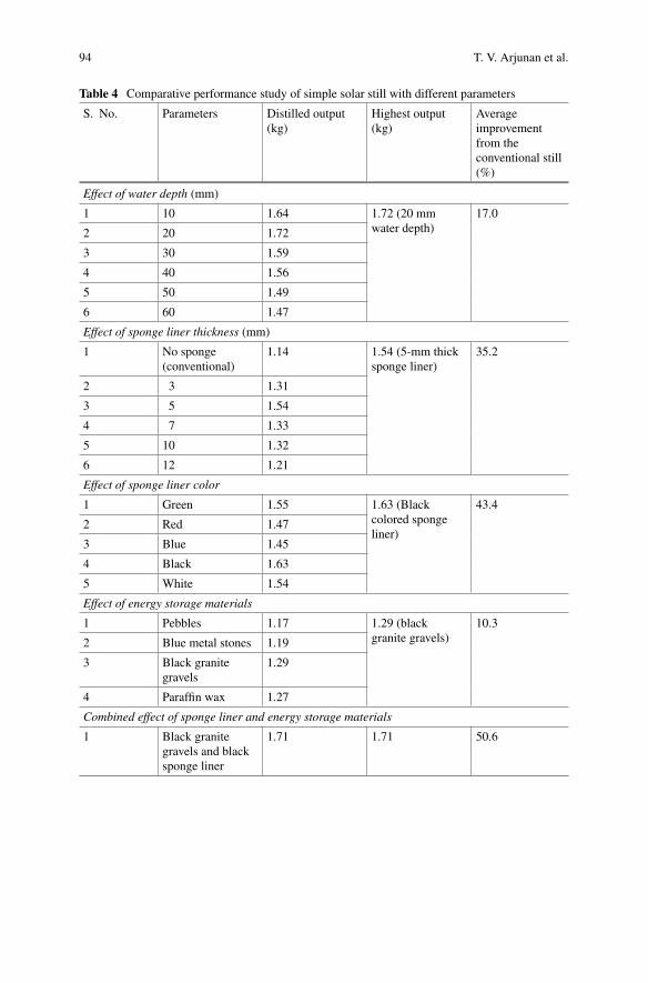
94 T. V. Arjunan et al.
Table 4 Comparative performance study of simple solar still with different parameters
S. No. Parameters Distilled output(kg)
Highest output(kg)
Averageimprovementfrom theconventional still(%)
Effect of water depth (mm)
1 10 1.64 1.72 (20 mmwater depth)
17.0
2 20 1.72
3 30 1.59
4 40 1.56
5 50 1.49
6 60 1.47
Effect of sponge liner thickness (mm)
1 No sponge(conventional)
1.14 1.54 (5-mm thicksponge liner)
35.2
2 3 1.31
3 5 1.54
4 7 1.33
5 10 1.32
6 12 1.21
Effect of sponge liner color
1 Green 1.55 1.63 (Blackcolored spongeliner)
43.4
2 Red 1.47
3 Blue 1.45
4 Black 1.63
5 White 1.54
Effect of energy storage materials
1 Pebbles 1.17 1.29 (blackgranite gravels)
10.3
2 Blue metal stones 1.19
3 Black granitegravels
1.29
4 Paraffin wax 1.27
Combined effect of sponge liner and energy storage materials
1 Black granitegravels and blacksponge liner
1.71 1.71 50.6
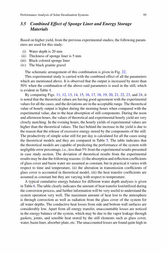
Performance Analysis of Solar Desalination Systems 95
3.5 Combined Effect of Sponge Liner and Energy StorageMaterials
Based on higher yield, from the previous experimental studies, the following param-eters are used for this study:
(i) Water depth is 20 mm(ii) Thickness of sponge liner is 5 mm(iii) Black colored sponge liner(iv) The black granite gravel
The schematic arrangement of this combination is given in Fig. 22.This experimental study is carried with the combined effect of all the parameters
which are mentioned above. It is observed that the output is increased by more than50% when the combination of the above-said parameters is used in the still, whichis evident in Table 4.
By comparing Figs. 11, 12, 13, 14, 15, 16, 17, 18, 19, 20, 21, 22, 23, and 24, itis noted that the theoretical values are having good agreement with the experimentalvalues for all the cases, and the deviations are in the acceptable range. The theoreticalvalue of hourly output is higher during the morning hours when compared with theexperimental value, due to the heat absorption of still components. During the noonand afternoon hours, the values of theoretical and experimental hourly yield are veryclosely matching. In the evening hours, the hourly yields of experimental values arehigher than the theoretical values. The fact behind the increase in the yield is due tothe reason that the release of excessive energy stored by the components of the still.The productivity of simple solar still for per day is calculated for all the cases usingthe theoretical models and they are compared in Table 5. The table indicates thatthe theoretical models are capable of predicting the performance of the system withnegligible error percentage, i.e., less than 5% from the experimental results presentedin case study section. The deviation of theoretical results from the experimentalresultsmay be due the following reasons: (i) the absorption and reflection coefficientsof glass cover and basin water are assumed as constant, but in practical it varies withrespect to time and temperature, (ii) the alteration in transmission coefficients ofglass cover is accounted in theoretical model, (iii) the heat transfer coefficients areassumed as constant but they are varying with respect to temperature.
A typical cumulative energy balance for different water depth analyses is givenin Table 6. The table clearly indicates the amount of heat transfer lost/utilized duringthe conversion process, and further information will be very useful to understand thesystem operation very well. The maximum amount of heat lost to the atmosphereis through convection as well as radiation from the glass cover of the system forall water depths. The conductive heat losses from side and bottom wall surfaces areconsiderably low. Apart from all energy transfer, unaccountable losses are noticedin the energy balance of the system, which may be due to the vapor leakage throughgaskets, joints, and sensible heat stored by the still elements such as glass cover,water, basin liner, absorber plate, etc. The unaccounted losses are found quite high in
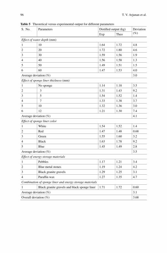
96 T. V. Arjunan et al.
Table 5 Theoretical versus experimental output for different parameters
S. No. Parameters Distilled output (kg) Deviation(%)Exp Theo
Effect of water depth (mm)
1 10 1.64 1.72 4.8
2 20 1.72 1.80 4.6
3 30 1.59 1.56 1.9
4 40 1.56 1.58 1.3
5 50 1.49 1.51 1.5
6 60 1.47 1.53 4.0
Average deviation (%) 3.0
Effect of sponge liner thickness (mm)
1 No sponge 1.14 1.18 3.5
2 3 1.31 1.43 9.2
3 5 1.54 1.52 1.4
4 7 1.33 1.38 3.7
5 10 1.32 1.36 3.0
6 12 1.21 1.30 7.4
Average deviation (%) 4.1
Effect of sponge liner color
1 White 1.54 1.52 1.4
2 Red 1.47 1.48 0.68
3 Green 1.55 1.60 3.2
4 Black 1.63 1.78 9.2
5 Blue 1.45 1.49 2.8
Average deviation (%) 3.5
Effect of energy storage materials
1 Pebbles 1.17 1.21 3.4
2 Blue metal stones 1.19 1.24 4.2
3 Black granite gravels 1.29 1.25 3.1
4 Paraffin wax 1.27 1.35 4.7
Combination of sponge liner and energy storage materials
1 Black granite gravels and black sponge liner 1.71 1.72 0.60
Average deviation (%) 3.1
Overall deviation (%) 3.68
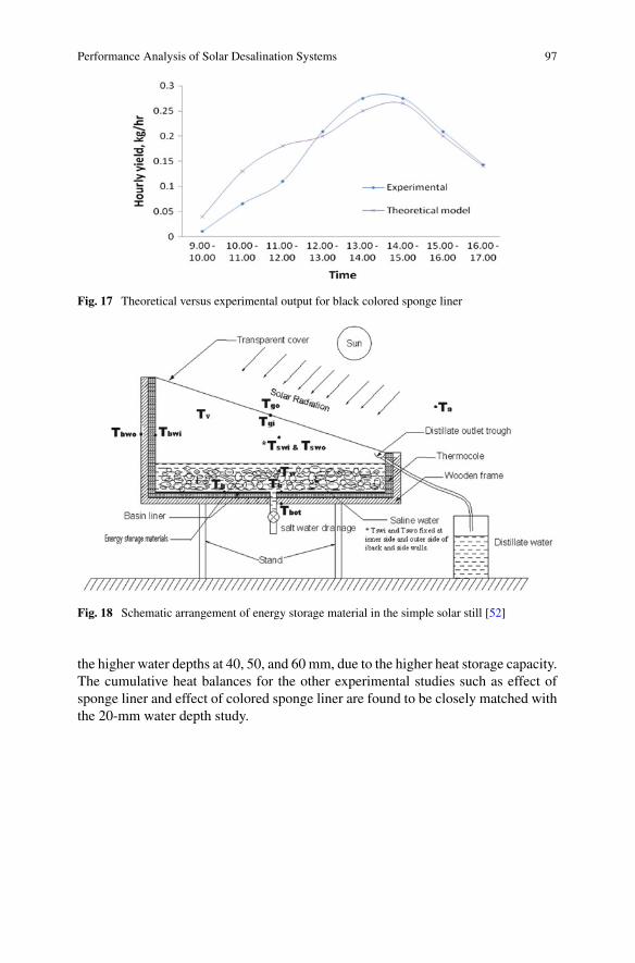
Performance Analysis of Solar Desalination Systems 97
Fig. 17 Theoretical versus experimental output for black colored sponge liner
Fig. 18 Schematic arrangement of energy storage material in the simple solar still [52]
the higher water depths at 40, 50, and 60 mm, due to the higher heat storage capacity.The cumulative heat balances for the other experimental studies such as effect ofsponge liner and effect of colored sponge liner are found to be closely matched withthe 20-mm water depth study.
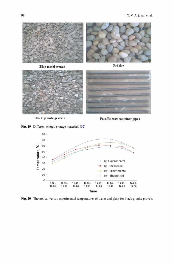
98 T. V. Arjunan et al.
Fig. 19 Different energy storage materials [52]
Fig. 20 Theoretical versus experimental temperatures of water and glass for black granite gravels
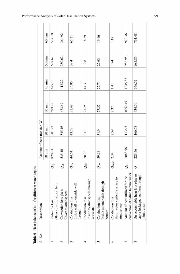
Performance Analysis of Solar Desalination Systems 99
Table6
Heatb
alance
ofstill
fordifferentw
ater
depths
S.No.
Descriptio
nAmount
ofheattransfer,W
10mm
20mm
30mm
40mm
50mm
60mm
1Radiatio
nloss
Glass
coverto
atmosphere
Qrg
820.63
801.77
693.98
625.13
597.62
577.10
2Convectionloss
glass
Cover
toatmosphere
Qcg
535.10
545.16
473.69
412.22
380.62
364.92
3Conductionloss
Inside
walltoou
tsidewall
through
Qbw
44.64
43.79
35.49
36.95
38.4
65.21
4Conductionloss
Inside
toatmospherethrough
sidewalls
Qsw
20.22
23.7
21.25
14.31
19.8
18.29
5Conductionloss
Inside
toouterside
through
botto
m
Qbo
t29.94
31.9
27.52
22.71
22.63
19.46
6Conductionloss
Basin
water
verticalsurfaceto
atmosphere
Qsw
w2.34
2.59
2.37
1.41
1.74
1.18
7Amount
ofheatutilizedforthe
conversion
ofsalin
eto
pure
water
Qd
1083.56
1136.51
1052.45
1045.83
982.95
972.36
8Unaccountableheatloss
(due
tovaporleakage,heatloss
through
joints,etc.)
Qu
223.56
166.68
434.50
656.52
685.86
761.48
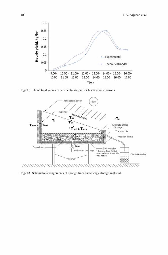
100 T. V. Arjunan et al.
Fig. 21 Theoretical versus experimental output for black granite gravels
Fig. 22 Schematic arrangements of sponge liner and energy storage material
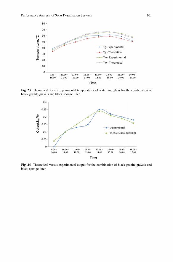
Performance Analysis of Solar Desalination Systems 101
Fig. 23 Theoretical versus experimental temperatures of water and glass for the combination ofblack granite gravels and black sponge liner
Fig. 24 Theoretical versus experimental output for the combination of black granite gravels andblack sponge liner
102 T. V. Arjunan et al.
4 Conclusions
This chapter presents an overview of theoretical modeling procedure for simple solardesalination systemand also reports the significant design and operational parametersof the system which affect the performance are tilt angle, thickness of glass, addi-tional condensers, reflectors, phase-change materials, flat plate and ETC collectors,nanofluids, basin water temperature, water depth, etc. An efficient solar desalinationsystem can be designed with thorough knowledge on the performance and the effectof various parameters. Developing theoretical model for solar desalination systems isan attractive alternative solution to develop and investigate enhanced designs underdifferent operational and climatically conditions. The theoretical models are verysimple and effective tools to design the system with various performance enhance-ment methods such as usage of energy storage materials and sponge liners. Thischapter also explores the capability of the theoretical models along with the casestudy.
References
1. Rajvanshi AK (1981) Effect of various dyes on solar distillation. Sol Energy 27(1):51–652. Okeke CE, Egarievwe SU, Animalu AOE (1990) Effects of coal and charcoal on solar-still
performance. Energy 15(11):1071–10733. Ouar MA, Sellami MH, Meddour SE, Touahir R, Guemari S, Loudiyi K (2017) Experimental
yield analysis of groundwater solar desalination system using absorbent materials. GroundwSustain Dev 5:261–267
4. Kabeel AE, Abdelgaied M, Eisa A (2018) Enhancing the performance of single basin solarstill using high thermal conductivity sensible storage materials. J Clean Prod 183:20–25
5. Deshmukh HS, Thombre SB (2017) Solar distillation with single basin solar still using sensibleheat storage materials. Desalination 410:91–98
6. FaeghM, ShafiiMB (2017) Experimental investigation of a solar still equippedwith an externalheat storage system using phase change materials and heat pipes. Desalination 409:128–135
7. Sharshir SW, Peng G, Wu L, Essa FA, Kabeel AE, Yang N (2017) The effects of flake graphitenanoparticles, phase change material, and film cooling on the solar still performance. ApplEnergy 191:358–366
8. Panchal H, Patel DK, Patel P (2018) Theoretical and experimental performance analysis ofsandstones and marble pieces as thermal energy storage materials inside solar stills. Int JAmbient Energy 39(3):221–229
9. Arjunan TV, Aybar HS, Nedunchezhian N (2017) Experimental study on enhancing the pro-ductivity of solar still using locally available material as a storage medium. J Inst Eng (India)Ser C 98(2):191–196
10. Panchal H, Patel P, Patel N, Thakkar H (2017) Performance analysis of solar still with differentenergy-absorbing materials. Int J Ambient Energy 38(3):224–228
11. Sarhaddi F, Tabrizi FF, Zoori HA, Mousavi SAHS (2017) Comparative study of two weir typecascade solar stills with and without PCM storage using energy and exergy analysis. EnergyConvers Manag 133:97–109
12. Kaushal AK, Mittal MK, Gangacharyulu D (2017) An experimental study of floating wickbasin type vertical multiple effect diffusion solar still with waste heat recovery. Desalination414:35–45
Performance Analysis of Solar Desalination Systems 103
13. Sharon H, Reddy KS, Krithika D, Philip L (2017) Experimental performance investigationof tilted solar still with basin and wick for distillate quality and enviro-economic aspects.Desalination 410:30–54
14. Pal P, Yadav P, Dev R, Singh D (2017) Performance analysis of modified basin type doubleslope multi–wick solar still. Desalination 422:68–82
15. Kabeel AE, Teamah MA, Abdelgaied M, Aziz GBA (2017) Modified pyramid solar still withv-corrugated absorber plate and PCM as a thermal storage medium. J Clean Prod 161:881–887
16. Rufuss DDW, Iniyan S, Suganthi L, Davies PA (2017) Nanoparticles enhanced phase changematerial (NPCM) as heat storage in solar still application for productivity enhancement. EnergyProcedia 141:45–49
17. Arunkumar T, Kabeel AE (2017) Effect of phase change material on concentric circular tubularsolar still-integration meets enhancement. Desalination 414:46–50
18. KabeelAE, El-SamadonyYAF,El-MaghlanyWM(2017) Theoretical performance comparisonof solar still using different PCM. In: Twentieth international water technology conference,IWTC20, pp 424–432
19. Shanmugan S, Palani S, Janarthanan B (2018) Productivity enhancement of solar still by PCMand nanoparticles miscellaneous basin absorbing materials. Desalination 433:186–198
20. Al-harahsheh M, Abu-Arabi M, Mousa H, Alzghoul Z (2018) Solar desalination using solarstill enhanced by external solar collector and PCM. Appl Therm Eng 128:1030–1040
21. Mahian O, Kianifar A, Heris SZ,Wen D, Sahin AZ,Wongwises S (2017) Nanofluids effects onthe evaporation rate in a solar still equipped with a heat exchanger. Nano Energy 36:134–155
22. Rashidi S, Akar S, BovandM, Ellahi R (2018) Volume of fluid model to simulate the nanofluidflow and entropy generation in a single slope solar still. Renew Energy 115:400–410
23. Thakur AK, Agarwal D, Khandelwal P, Dev S (2018) Comparative study and yield productivityof nano-paint and nano-fluid used in a passive-type single basin solar still. In: Advances in smartgrid and renewable energy. Springer, Singapore, pp 709–716
24. Kabeel AE, Omara ZM, Essa FA (2017) Numerical investigation of modified solar still usingnanofluids and external condenser. J Taiwan Inst Chem Eng 75:77–86
25. Rashidi S, Bovand M, Rahbar N, Esfahani JA (2018) Steps optimization and productivityenhancement in a nanofluid cascade solar still. Renew Energy 118:536–545
26. Chen W, Zou C, Li X, Li L (2017) Experimental investigation of SiC nanofluids for solardistillation system: stability, optical properties and thermal conductivity with saline water-based fluid. Int J Heat Mass Transf 107:264–270
27. Sharshir SW, Peng G, Wu L, Yang N, Essa FA, Elsheikh AH, Kabeel AE (2017) Enhancingthe solar still performance using nanofluids and glass cover cooling: experimental study. ApplTherm Eng 113:684–693
28. Kerfah R, Noura B, Meraimi Z, Zeghmati B (2017) Experimental investigation of basin solarstill with additional condensation chamber underAlgerian climatic conditions. J RenewSustainEnergy 9(3):033704
29. Suganthi L, Iniyan S, Rufuss DDW (2018) Combined effect of heat storage, reflective material,and additional heat source on the productivity of a solar still—techno-economic approach. JTest Eval 46(6)
30. Panchal HN, Shah PK (2013) Performance analysis of double basin solar still with evacuatedtubes. Appl Solar Energy 49(3):174–179
31. Dhindsa GS, Mittal MK (2018) Experimental study of basin type vertical multiple effect diffu-sion solar still integrated with mini solar pond to generate nocturnal distillate. Energy ConversManag 165:669–680
32. Panchal H, Mohan I (2017) Various methods applied to solar still for enhancement of distillateoutput. Desalination 415:76–89
33. Rahimi-Ahar Z, Hatamipour MS, Ghalavand Y (2018) Experimental investigation of asolar vacuum humidification-dehumidification (VHDH) desalination system. Desalination437:73–80
34. El-Samadony YAF, Kabeel AE (2014) Theoretical estimation of the optimum glass cover waterfilm cooling parameters combinations of a stepped solar still. Energy 68:744–750
104 T. V. Arjunan et al.
35. Mousa HA (1997) Water film cooling over the glass cover of a solar still including evaporationeffects. Energy 22(1):43–48
36. Mazraeh AE, Babayan M, Yari M, Sefidan AM, Saha SC (2018) Theoretical study on theperformance of a solar still system integrated with PCM-PV module for sustainable water andpower generation. Desalination 443:184–197
37. Dumka P, Mishra DR (2018) Energy and exergy analysis of conventional and modified solarstill integrated with sand bed earth: Study of heat and mass transfer. Desalination 437:15–25
38. Muftah AF, Sopian K, Alghoul MA (2018) Performance of basin type stepped solar stillenhanced with superior design concepts. Desalination 435:198–209
39. Xie G, Sun L, Yan T, Tang J, Bao J, Du M (2018) Model development and experimentalverification for tubular solar still operating under vacuum condition. Energy 157:115–130
40. Naroei M, Sarhaddi F, Sobhnamayan F (2018) Efficiency of a photovoltaic thermal steppedsolar still: experimental and numerical analysis. Desalination 441:87–95
41. Rahbar N, Asadi A, Fotouhi-Bafghi E (2018) Performance evaluation of two solar stills ofdifferent geometries: tubular versus triangular: experimental study, numerical simulation, andsecond law analysis. Desalination 443:44–55
42. Kalbasi R, Alemrajabi AA, Afrand M (2018) Thermal modeling and analysis of single anddouble effect solar stills: an experimental validation. Appl Therm Eng 129:1455–1465
43. Malaeb L, Aboughali K, Ayoub GM (2016) Modeling of a modified solar still system withenhanced productivity. Sol Energy 125:360–372
44. Arjunan TV, Aybar HS, Nedunchezhian N (2011) Effect of sponge liner on the internal heattransfer coefficients in a simple solar still. Desalin Water Treat 29(1–3):271–284
45. Badran OO, Abu-Khader MM (2007) Evaluating thermal performance of a single slope solarstill. Heat Mass Transf 43(10):985–995
46. Edalatpour M, Kianifar A, Ghiami S (2015) Effect of blade installation on heat transfer andfluid flow within a single slope solar still. Int Commun Heat Mass Transfer 66:63–70
47. Chen Z, Yao Y, Zheng Z, Zheng H, Yang Y, Hou LA, Chen G (2013) Analysis of the character-istics of heat and mass transfer of a three-effect tubular solar still and experimental research.Desalination 330:42–48
48. Singh AK, Tiwari GN (1993) Thermal evaluation of regenerative active solar distillation underthermosyphon mode. Energy Convers Manag 34:697–706
49. El-Samadony YAF, El-Maghlany WM, Kabeel AE (2016) Influence of glass cover inclinationangle on radiation heat transfer rate within stepped solar still. Desalination 384:68–77
50. Prakash J, Kavathekar AK (1986) Performance prediction of a regenerative solar still. Solar &Wind Technology 3(2):119–125
51. Arjunan TV, Aybar HS, Nedunchezhian N (2011) The effect of sponge liner on the performanceof simple solar still. Int J Renew Energy Technol 2(2):169–192
52. Arjunan TV, Aybar H, Neelakrishnan S, Sampathkumar K, Amjad S, Subramanian R,Nedunchezhian N (2012) The effect of sponge liner colors on the performance of simplesolar stills. Energy Sour Part A Recovery Util Environ Effects 34(21):1984–1994
53. Arjunan TV, Aybar HS, Sadagopan P, SaratChandran B, Neelakrishnan S, Nedunchezhian N(2014) The effect of energy storage materials on the performance of a simple solar still. EnergySources Part A Recovery Util Environ Effects 36(2):131–141
Application of Software in PredictingThermal Behaviours of Solar Stills
Anirshu DevRoy, Om Prakash, Shobhana Singh and Anil Kumar
Abstract Software plays a major role in analysis and simulation of solar stills.These simulation techniques are very much cheaper and time saving compared tothe experimental analysis of a system. This chapter explains the different softwareused for the design and testing of various models of solar still. It also gives anoverall idea of what type of software being used and its feasibility. Software likeMATLAB, ANSYS and FLUENT have been taken into account here for modellingand development of various solar stills. Moreover, software such as SPSS is oftenused for statistical data analysis. All recent software have been selected and reviewedand the benefits explained.
Keywords Solar still · Simulation · Modelling · CFD · FORTRAN · MATLAB ·SPSS
Nomenclature
A Area, m2
Ag Aspect ratio for glass A = L/HC Vapour concentration of air, kg m−3
c Specific heat, J kg−1 °C−1
Cp Specific heat capacity at constant pressure, J kg−1 K−1
A. DevRoyDepartment of Mechanical Engineering,Jalpaiguri Government Engineering College, Jalpaiguri, India
O. Prakash (B)Department of Mechanical Engineering, Birla Institute of Technology Mesra,Ranchi 835215, Indiae-mail: [email protected]
S. SinghDepartment of Energy Technology, Aalborg University, 9220 Aalborg East, Denmark
A. KumarDepartment of Mechanical Engineering, Delhi Technological University, Delhi 110042, India
© Springer Nature Singapore Pte Ltd. 2019A. Kumar and O. Prakash (eds.), Solar Desalination Technology,Green Energy and Technology, https://doi.org/10.1007/978-981-13-6887-5_5
105
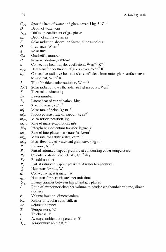
106 A. DevRoy et al.
Cwg Specific heat of water and glass cover, J kg−1 °C−1
D Depth of water, cmDag Diffusion coefficient of gas phasedw Depth of saline water, mF Solar radiation absorption factor, dimensionlessG Irradiance, W m−2
g Solar fluxGn Grashoff’s numberH Solar irradiation, kWh/m2
h Convection heat transfer coefficient, W m−2 K−1
hglc Heat transfer coefficient of glass cover, W/m2 Kh p Convective radiative heat transfer coefficient from outer glass surface cover
to ambient, W/m2 KIt Tilt of incident solar radiation, W m−2
Is(t) Solar radiation over the solar still glass cover, W/m2
K Thermal conductivityLe Lewis numberLv Latent heat of vaporization, J/kgm Specific mass, kg/m2
m ′b Mass rate of brine, kg m−3
m ′ev Produced mass rate of vapour, kg m−3
meva Mass for evaporation, kgmevap Rate of mass evaporation, m/sMgl Interphase momentum transfer, kg/m2 s2
m lg Rate of interphase mass transfer, kg/m3
m ′sw Mass rate for saline water, kg m−3
mwg Mass flow rate of water and glass cover, kg s−1
P Pressure, N/m2
Pci Partial saturated vapour pressure at condensing cover temperaturePd Calculated daily productivity, 1/m2 dayPr Prandtl numberPv Partial saturated vapour pressure at water temperatureQ Heat transfer rate, Wqa Convective heat transfer, Wqe,v Heat transfer per unit area per unit timeQlg Energy transfer between liquid and gas phasesR Ratio of evaporator chamber volume to condenser chamber volume, dimen-
sionlessr Volume fraction, dimensionlessRd Radius of tubular solar still, mSc Schmidt numberT Temperature, °Ct Thickness, mta Average ambient temperature, °CTam Temperature ambient, °C
Application of Software in Predicting Thermal Behaviours … 107
Tg Glass temperature, °CTgin Inner glass surface temperature, °CTgout Outer glass cover temperature, °CTv Water temperature, °CU Side heat loss coefficient from basin to ambient, W m−2 K−1
u X component of velocity, m s−1
Ueva Heat transfer coefficient for evaporation, W/m2 KV Velocity vector, m/sv Y component of velocity, m s−1
W Wind velocity, m/sw Compressor power, wXA Mass fraction of liquid phaseYA Mass fraction of gas phaseyb Concentration of salt in brine, mg l−1
ysw Concentration of salts in feeding water, mg l−1
Greek Symbols
β Reflectivityγ Thermal diffusivity of air, m2 s−1
λ/ϕ Brine depth to frontal height, –ϕg Latitude of glass cover, °ϕw Latitude of water, °φ Glass inclination angle, °ρ Density, kg/m3
σ Stefan–Boltzmann constant (5.67 × 10⁻⁸ Wm2 K−4)μ Viscosity, kg/m sχ Feed concentration factor
Subscripts
1 Initiala AirB Baseb Direct beam of solar radiationBs Basinc Convectivee Evaporativeeff Effectiveev Evaporator
108 A. DevRoy et al.
f Refrigerationg Glassl Side lossLiq Liquidrad Radiativev Water
1 Introduction
The harnessing of solar energy began in 1839 when Alexandre Edmond Becquereldiscovered that certain materials produce small amount of electric current whenexposed to light [1]. Henceforth, solar energy is being used in some productivemanner other than natural use. Now in the twenty-first century with drastic increasein human population, the non-renewable energy resources are being exhausted at veryhigh rate. The demand for renewable energy has increased, and this leads to massivedevelopment in alternative energy sources like solar, wind, water, geothermal. Newdesigns and developments are being done causing lesser pollution and at low costwith high efficiency.
Altogether, serious steps are being taken for conserving the natural habitat. Nownatural habitat is composed of soil, air, water, etc. Considering water, although theworld has abundance of water, fresh water is of only 2% of the world’s water supply.In recent times, with the increase in population, fresh water in the world is decreasingat an alarming rate, which leads to alternative methods for extracting fresh water [2].One of them is the usage of solar still to extract fresh water from impure water. Solarstill is having its use since the pre-Incaian period. After that, various types of designsand modifications have been suggested and implemented. The solar still distils waterusing the heat of the sun to evaporate and then cool and collect it. The applicationof solar still is not just extraction of pure distilled water but to provide fresh waterin regions where the freshwater availability is not easy. Using solar still, fresh watercan be obtained easily at a low cost, but like all other conventional devices, it is quitetime-consuming. However, the fresh water finally available is in a very low quantity.Various modifications in design are made to increase the usability of the solar stillbased on different categories to enhance its productivity. Some of the methods toincrease the productivity of a solar still are to change its shape or the materials usedwhich absorb large amount of heat energy, using the optimum angle of inclination,etc. [3].
Figure 1 illustrates the basic design of a solar still; here, the contaminated waterlies at the bottom of the container, and due to solar radiation, water gets evaporatedand condensed water droplets are formed on the upper glass cover which is finallycollected as fresh water. Now each category of solar still has various types of designbased on its shape and size. Each produces a different amount of fresh water and hasvarious merits and demerits. All these types are experimented individually, and thedata are used by various researchers and manufacturers across the globe. Now an
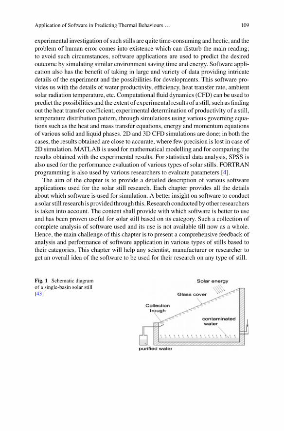
Application of Software in Predicting Thermal Behaviours … 109
experimental investigation of such stills are quite time-consuming and hectic, and theproblem of human error comes into existence which can disturb the main reading;to avoid such circumstances, software applications are used to predict the desiredoutcome by simulating similar environment saving time and energy. Software appli-cation also has the benefit of taking in large and variety of data providing intricatedetails of the experiment and the possibilities for developments. This software pro-vides us with the details of water productivity, efficiency, heat transfer rate, ambientsolar radiation temperature, etc. Computational fluid dynamics (CFD) can be used topredict the possibilities and the extent of experimental results of a still, such as findingout the heat transfer coefficient, experimental determination of productivity of a still,temperature distribution pattern, through simulations using various governing equa-tions such as the heat and mass transfer equations, energy and momentum equationsof various solid and liquid phases. 2D and 3D CFD simulations are done; in both thecases, the results obtained are close to accurate, where few precision is lost in case of2D simulation. MATLAB is used for mathematical modelling and for comparing theresults obtained with the experimental results. For statistical data analysis, SPSS isalso used for the performance evaluation of various types of solar stills. FORTRANprogramming is also used by various researchers to evaluate parameters [4].
The aim of the chapter is to provide a detailed description of various softwareapplications used for the solar still research. Each chapter provides all the detailsabout which software is used for simulation. A better insight on software to conducta solar still research is provided through this.Research conducted byother researchersis taken into account. The content shall provide with which software is better to useand has been proven useful for solar still based on its category. Such a collection ofcomplete analysis of software used and its use is not available till now as a whole.Hence, the main challenge of this chapter is to present a comprehensive feedback ofanalysis and performance of software application in various types of stills based totheir categories. This chapter will help any scientist, manufacturer or researcher toget an overall idea of the software to be used for their research on any type of still.
Fig. 1 Schematic diagramof a single-basin solar still[43]
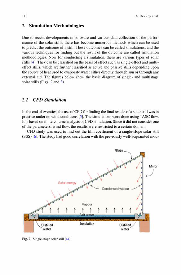
110 A. DevRoy et al.
2 Simulation Methodologies
Due to recent developments in software and various data collection of the perfor-mance of the solar stills, there has become numerous methods which can be usedto predict the outcome of a still. These outcomes can be called simulations, and thevarious techniques for finding out the result of the outcome are called simulationmethodologies. Now for conducting a simulation, there are various types of solarstills [4]. They can be classified on the basis of effect such as single-effect and multi-effect stills, which are further classified as active and passive stills depending uponthe source of heat used to evaporate water either directly through sun or through anyexternal aid. The figures below show the basic diagram of single- and multistagesolar stills (Figs. 2 and 3).
2.1 CFD Simulation
In the end of twenties, the use of CFD for finding the final results of a solar still was inpractice under no wind conditions [5]. The simulations were done using TASC flow.It is based on finite volume analysis of CFD simulation. Since it did not consider oneof the parameters, wind flow, the results were restricted to a certain domain.
CFD study was used to find out the film coefficient of a single-slope solar still(SSS) [6]. The study had good correlation with the previously well-acquainted mod-
Fig. 2 Single-stage solar still [44]
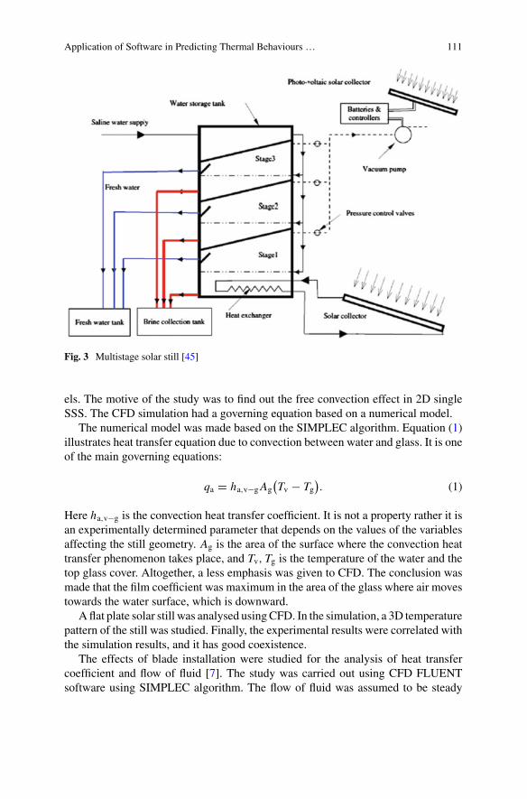
Application of Software in Predicting Thermal Behaviours … 111
Fig. 3 Multistage solar still [45]
els. The motive of the study was to find out the free convection effect in 2D singleSSS. The CFD simulation had a governing equation based on a numerical model.
The numerical model was made based on the SIMPLEC algorithm. Equation (1)illustrates heat transfer equation due to convection between water and glass. It is oneof the main governing equations:
qa = ha,v−gAg(Tv − Tg
). (1)
Here ha,v−g is the convection heat transfer coefficient. It is not a property rather it isan experimentally determined parameter that depends on the values of the variablesaffecting the still geometry. Ag is the area of the surface where the convection heattransfer phenomenon takes place, and Tv, Tg is the temperature of the water and thetop glass cover. Altogether, a less emphasis was given to CFD. The conclusion wasmade that the film coefficient was maximum in the area of the glass where air movestowards the water surface, which is downward.
A flat plate solar still was analysed usingCFD. In the simulation, a 3D temperaturepattern of the still was studied. Finally, the experimental results were correlated withthe simulation results, and it has good coexistence.
The effects of blade installation were studied for the analysis of heat transfercoefficient and flow of fluid [7]. The study was carried out using CFD FLUENTsoftware using SIMPLEC algorithm. The flow of fluid was assumed to be steady
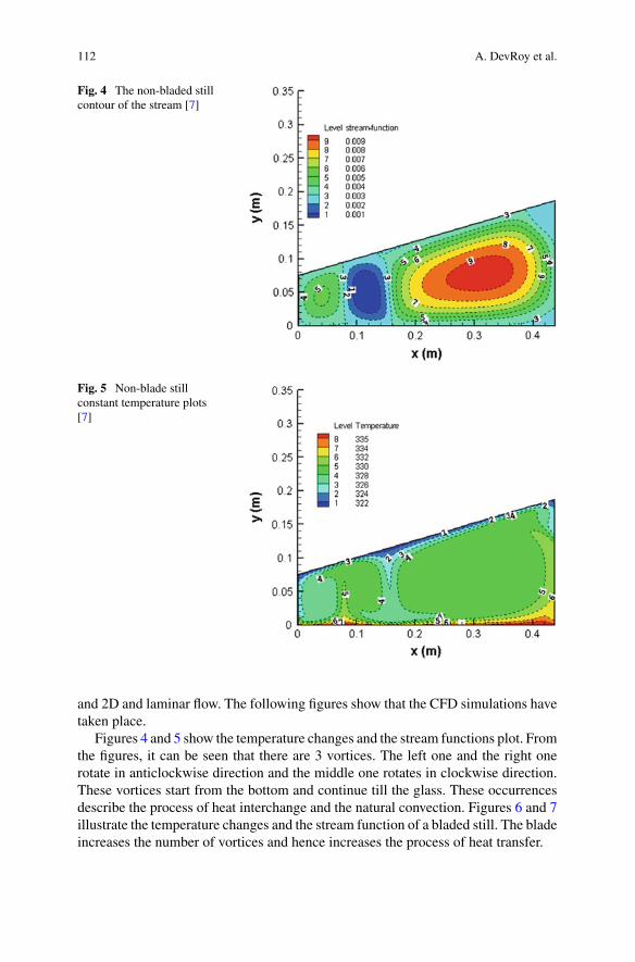
112 A. DevRoy et al.
Fig. 4 The non-bladed stillcontour of the stream [7]
Fig. 5 Non-blade stillconstant temperature plots[7]
and 2D and laminar flow. The following figures show that the CFD simulations havetaken place.
Figures 4 and 5 show the temperature changes and the stream functions plot. Fromthe figures, it can be seen that there are 3 vortices. The left one and the right onerotate in anticlockwise direction and the middle one rotates in clockwise direction.These vortices start from the bottom and continue till the glass. These occurrencesdescribe the process of heat interchange and the natural convection. Figures 6 and 7illustrate the temperature changes and the stream function of a bladed still. The bladeincreases the number of vortices and hence increases the process of heat transfer.
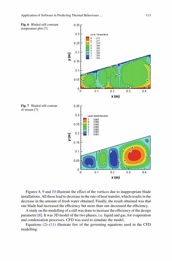
Application of Software in Predicting Thermal Behaviours … 113
Fig. 6 Bladed still constanttemperature plot [7]
Fig. 7 Bladed still contourof stream [7]
Figures 8, 9 and 10 illustrate the effect of the vortices due to inappropriate bladeinstallations. All these lead to decrease in the rate of heat transfer, which results in thedecrease in the amount of fresh water obtained. Finally, the result obtained was thatone blade had increased the efficiency but more than one decreased the efficiency.
A study on themodelling of a still was done to increase the efficiency of the designparameter [8]. It was 3D model of the two phases, i.e. liquid and gas, for evaporationand condensation processes. CFD was used to simulate the model.
Equations (2)–(11) illustrate few of the governing equations used in the CFDmodelling:
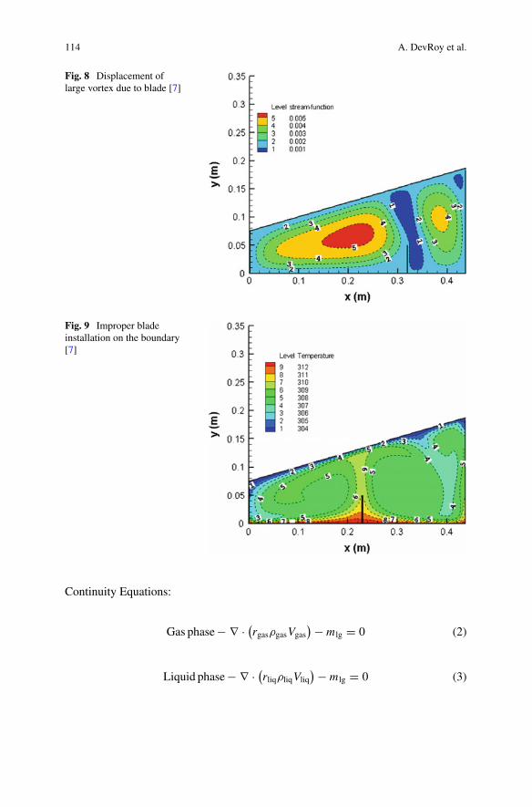
114 A. DevRoy et al.
Fig. 8 Displacement oflarge vortex due to blade [7]
Fig. 9 Improper bladeinstallation on the boundary[7]
Continuity Equations:
Gas phase− ∇ · (rgasρgasVgas
) − m lg = 0 (2)
Liquid phase− ∇ · (rliqρliqVliq
) − m lg = 0 (3)
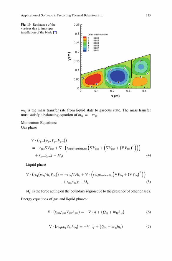
Application of Software in Predicting Thermal Behaviours … 115
Fig. 10 Resistance of thevortices due to improperinstallation of the blade [7]
m lg is the mass transfer rate from liquid state to gaseous state. The mass transfermust satisfy a balancing equation of m lg = −mgl.
Momentum Equations:Gas phase
∇ · (rgas
(ρgasVgasVgas
))
= −rgas∇Pgas + ∇ ·(rgasμlaminar,gas
(∇Vgas +
(∇Vgas + (∇Vgas
)T)))
+ rgasρgasg − Mgl (4)
Liquid phase
∇ · (rliq
(ρliqVliqVliq
)) = −rliq∇Pliq + ∇ ·(rliqμlaminar,liq
(∇Vliq + (∇Vliq
)T))
+ rliqρliqg + Mgl (5)
Mgl is the force acting on the boundary region due to the presence of other phases.
Energy equations of gas and liquid phases:
∇ · (rgasρgasVgashgas
) = −∇ · q + (Qlg + m lghlg
)(6)
∇ · (rliqρliqVliqhliq
) = −∇ · q + (Qlq + m lghlg
)(7)
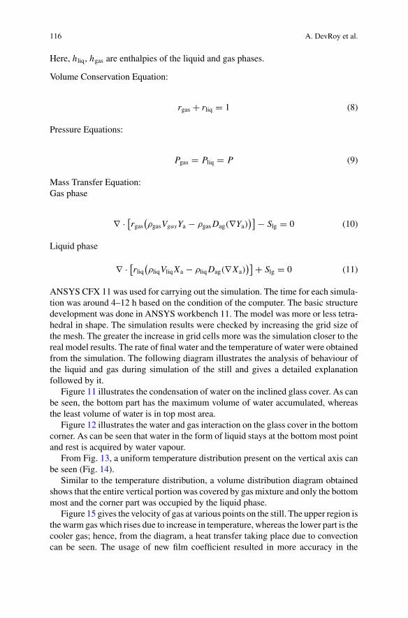
116 A. DevRoy et al.
Here, hliq, hgas are enthalpies of the liquid and gas phases.
Volume Conservation Equation:
rgas + rliq = 1 (8)
Pressure Equations:
Pgas = Pliq = P (9)
Mass Transfer Equation:Gas phase
∇ · [rgas
(ρgasVgasYa − ρgasDag(∇Ya)
)] − Slg = 0 (10)
Liquid phase
∇ · [rliq
(ρliqVliqXa − ρliqDag(∇Xa)
)] + Slg = 0 (11)
ANSYS CFX 11 was used for carrying out the simulation. The time for each simula-tion was around 4–12 h based on the condition of the computer. The basic structuredevelopment was done in ANSYS workbench 11. The model was more or less tetra-hedral in shape. The simulation results were checked by increasing the grid size ofthe mesh. The greater the increase in grid cells more was the simulation closer to thereal model results. The rate of final water and the temperature of water were obtainedfrom the simulation. The following diagram illustrates the analysis of behaviour ofthe liquid and gas during simulation of the still and gives a detailed explanationfollowed by it.
Figure 11 illustrates the condensation of water on the inclined glass cover. As canbe seen, the bottom part has the maximum volume of water accumulated, whereasthe least volume of water is in top most area.
Figure 12 illustrates the water and gas interaction on the glass cover in the bottomcorner. As can be seen that water in the form of liquid stays at the bottom most pointand rest is acquired by water vapour.
From Fig. 13, a uniform temperature distribution present on the vertical axis canbe seen (Fig. 14).
Similar to the temperature distribution, a volume distribution diagram obtainedshows that the entire vertical portion was covered by gas mixture and only the bottommost and the corner part was occupied by the liquid phase.
Figure 15 gives the velocity of gas at various points on the still. The upper region isthe warm gas which rises due to increase in temperature, whereas the lower part is thecooler gas; hence, from the diagram, a heat transfer taking place due to convectioncan be seen. The usage of new film coefficient resulted in more accuracy in the
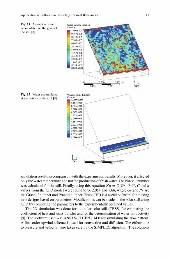
Application of Software in Predicting Thermal Behaviours … 117
Fig. 11 Amount of wateraccumulated on the glass ofthe still [8]
Fig. 12 Water accumulatedat the bottom of the still [8]
simulation results in comparison with the experimental results. Moreover, it affectedonly thewater temperature and not the production of freshwater. TheNusselt numberwas calculated for the still. Finally, using this equation Nu = C(Gr · Pr)n , C and nvalues from the CFD model were found to be 2.054 and 1.66, where Gr and Pr arethe Grashof number and Prandtl number. Thus, CFD is a useful software for makingnew designs based on parameters. Modifications can be made on the solar still usingCFD by comparing the parameters to the experimentally obtained values.
The 2D simulation was done for a tubular solar still (TBSS) for estimating thecoefficient of heat and mass transfer and for the determination of water productivity[9]. The software used was ANSYS-FLUENT 14.0 for simulating the flow pattern.A first-order upwind scheme is used for convection and diffusion. The effects dueto pressure and velocity were taken care by the SIMPLEC algorithm. The solutions
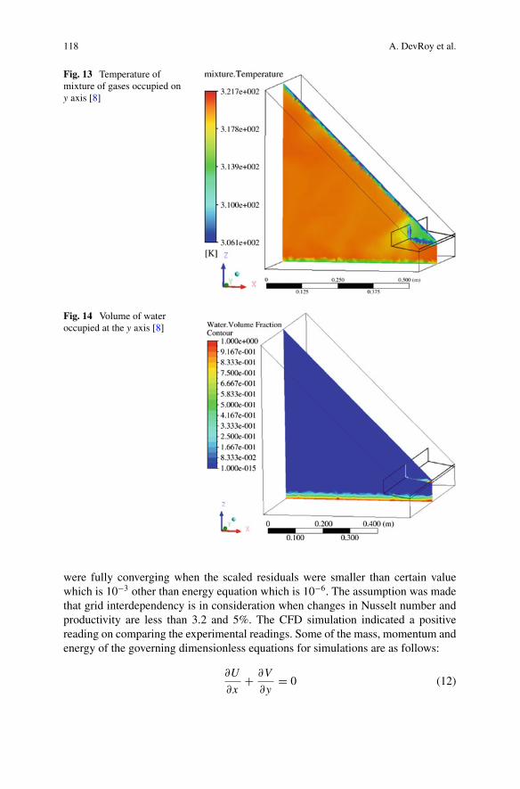
118 A. DevRoy et al.
Fig. 13 Temperature ofmixture of gases occupied ony axis [8]
Fig. 14 Volume of wateroccupied at the y axis [8]
were fully converging when the scaled residuals were smaller than certain valuewhich is 10−3 other than energy equation which is 10−6. The assumption was madethat grid interdependency is in consideration when changes in Nusselt number andproductivity are less than 3.2 and 5%. The CFD simulation indicated a positivereading on comparing the experimental readings. Some of the mass, momentum andenergy of the governing dimensionless equations for simulations are as follows:
∂U
∂x+ ∂V
∂y= 0 (12)
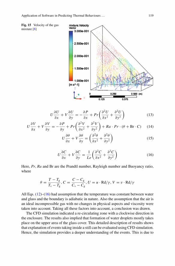
Application of Software in Predicting Thermal Behaviours … 119
Fig. 15 Velocity of the gasmixture [8]
U∂U
∂x+ V
∂U
∂y= −∂P
∂x+ Pr
(∂2U
∂x2+ ∂2U
∂y2
)(13)
U∂V
∂x+ V
∂V
∂y= −∂P
∂y+ Pr
(∂2V
∂x2+ ∂2V
∂y2
)+ Ra · Pr · (θ + Br · C) (14)
U∂θ
∂x+ V
∂θ
∂y=
(∂2θ
∂x2+ ∂2θ
∂y2
)(15)
U∂C
∂x+ V
∂C
∂y= 1
Le
(∂2C
∂x2+ ∂2C
∂y2
)(16)
Here, Pr, Ra and Br are the Prandtl number, Rayleigh number and Buoyancy ratio,where
θ = T − TgTv − Tg
,C = C − Cg
Cv − Cg,U = u · Rd/γ, V = v · Rd/γ
All Eqs. (12)–(16) had assumption that the temperature was constant between waterand glass and the boundary is adiabatic in nature. Also the assumption that the air isan ideal incompressible gas with no changes in physical aspects and viscosity weretaken into account. Taking all these factors into account, a conclusion was drawn.
The CFD simulation indicated a re-circulating zone with a clockwise direction inthe enclosure. The results also implied that formation of water droplets mostly takesplace on the upper area of the glass cover. This detailed description of results showsthat explanation of events taking inside a still can be evaluated using CFD simulation.Hence, the simulation provides a deeper understanding of the events. This is due to
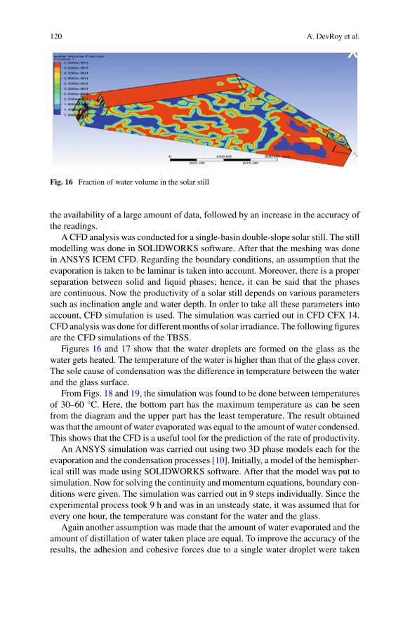
120 A. DevRoy et al.
Fig. 16 Fraction of water volume in the solar still
the availability of a large amount of data, followed by an increase in the accuracy ofthe readings.
A CFD analysis was conducted for a single-basin double-slope solar still. The stillmodelling was done in SOLIDWORKS software. After that the meshing was donein ANSYS ICEM CFD. Regarding the boundary conditions, an assumption that theevaporation is taken to be laminar is taken into account. Moreover, there is a properseparation between solid and liquid phases; hence, it can be said that the phasesare continuous. Now the productivity of a solar still depends on various parameterssuch as inclination angle and water depth. In order to take all these parameters intoaccount, CFD simulation is used. The simulation was carried out in CFD CFX 14.CFDanalysiswas done for differentmonths of solar irradiance. The following figuresare the CFD simulations of the TBSS.
Figures 16 and 17 show that the water droplets are formed on the glass as thewater gets heated. The temperature of the water is higher than that of the glass cover.The sole cause of condensation was the difference in temperature between the waterand the glass surface.
From Figs. 18 and 19, the simulation was found to be done between temperaturesof 30–60 °C. Here, the bottom part has the maximum temperature as can be seenfrom the diagram and the upper part has the least temperature. The result obtainedwas that the amount of water evaporated was equal to the amount of water condensed.This shows that the CFD is a useful tool for the prediction of the rate of productivity.
An ANSYS simulation was carried out using two 3D phase models each for theevaporation and the condensation processes [10]. Initially, a model of the hemispher-ical still was made using SOLIDWORKS software. After that the model was put tosimulation. Now for solving the continuity andmomentum equations, boundary con-ditions were given. The simulation was carried out in 9 steps individually. Since theexperimental process took 9 h and was in an unsteady state, it was assumed that forevery one hour, the temperature was constant for the water and the glass.
Again another assumption was made that the amount of water evaporated and theamount of distillation of water taken place are equal. To improve the accuracy of theresults, the adhesion and cohesive forces due to a single water droplet were taken
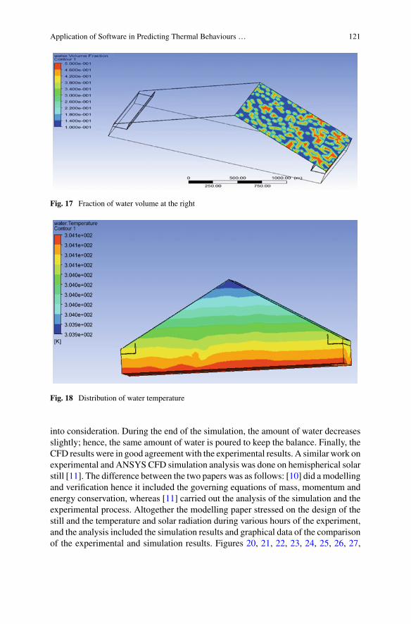
Application of Software in Predicting Thermal Behaviours … 121
Fig. 17 Fraction of water volume at the right
Fig. 18 Distribution of water temperature
into consideration. During the end of the simulation, the amount of water decreasesslightly; hence, the same amount of water is poured to keep the balance. Finally, theCFD results were in good agreement with the experimental results. A similar work onexperimental and ANSYS CFD simulation analysis was done on hemispherical solarstill [11]. The difference between the two papers was as follows: [10] did a modellingand verification hence it included the governing equations of mass, momentum andenergy conservation, whereas [11] carried out the analysis of the simulation and theexperimental process. Altogether the modelling paper stressed on the design of thestill and the temperature and solar radiation during various hours of the experiment,and the analysis included the simulation results and graphical data of the comparisonof the experimental and simulation results. Figures 20, 21, 22, 23, 24, 25, 26, 27,
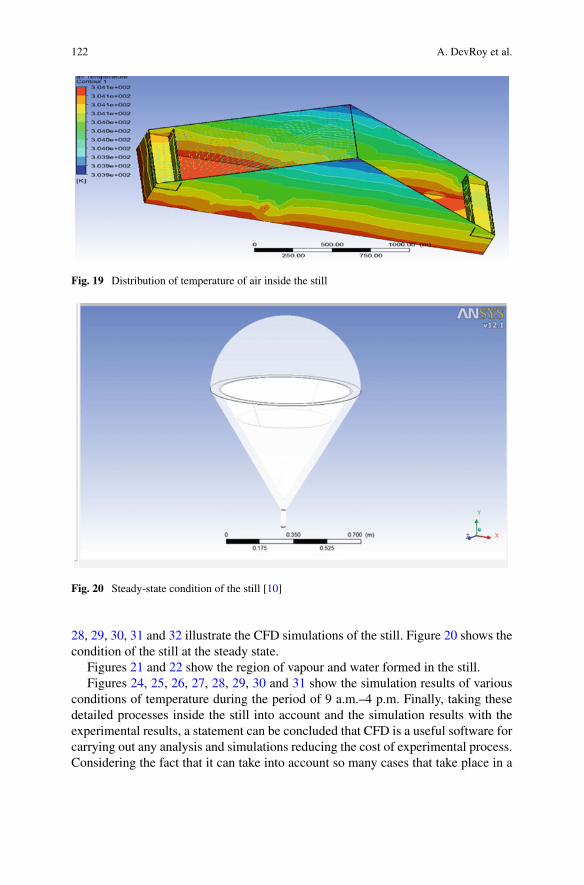
122 A. DevRoy et al.
Fig. 19 Distribution of temperature of air inside the still
Fig. 20 Steady-state condition of the still [10]
28, 29, 30, 31 and 32 illustrate the CFD simulations of the still. Figure 20 shows thecondition of the still at the steady state.
Figures 21 and 22 show the region of vapour and water formed in the still.Figures 24, 25, 26, 27, 28, 29, 30 and 31 show the simulation results of various
conditions of temperature during the period of 9 a.m.–4 p.m. Finally, taking thesedetailed processes inside the still into account and the simulation results with theexperimental results, a statement can be concluded that CFD is a useful software forcarrying out any analysis and simulations reducing the cost of experimental process.Considering the fact that it can take into account so many cases that take place in a
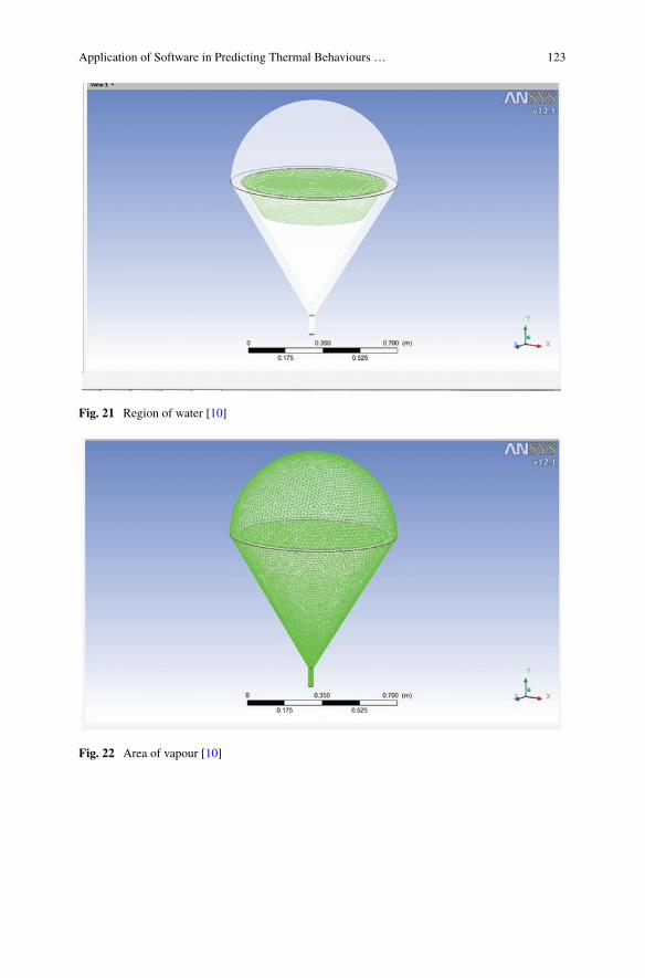
Application of Software in Predicting Thermal Behaviours … 123
Fig. 21 Region of water [10]
Fig. 22 Area of vapour [10]
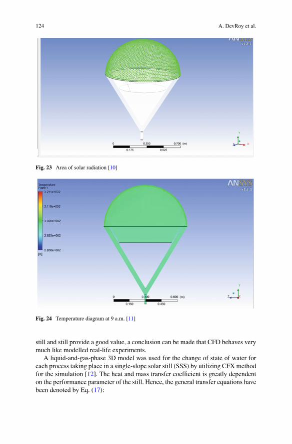
124 A. DevRoy et al.
Fig. 23 Area of solar radiation [10]
Fig. 24 Temperature diagram at 9 a.m. [11]
still and still provide a good value, a conclusion can be made that CFD behaves verymuch like modelled real-life experiments.
A liquid-and-gas-phase 3D model was used for the change of state of water foreach process taking place in a single-slope solar still (SSS) by utilizing CFXmethodfor the simulation [12]. The heat and mass transfer coefficient is greatly dependenton the performance parameter of the still. Hence, the general transfer equations havebeen denoted by Eq. (17):
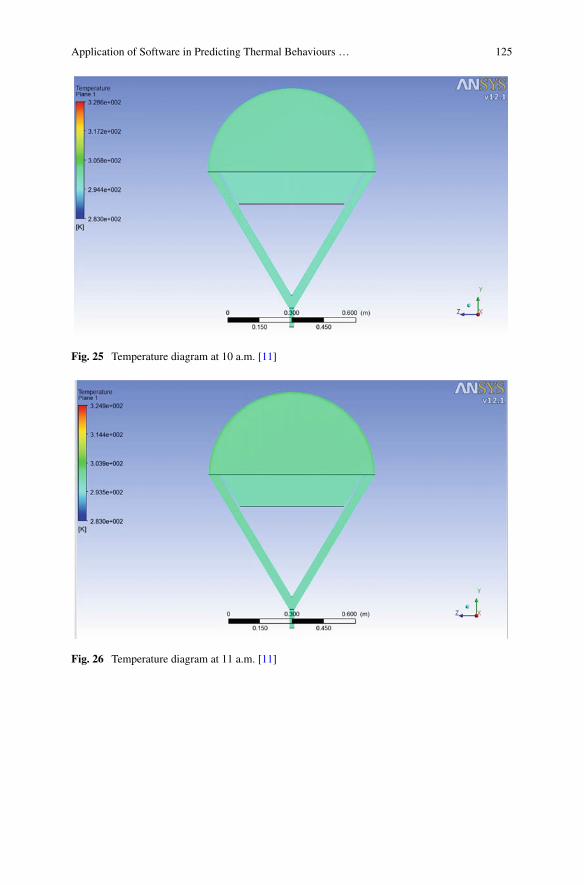
Application of Software in Predicting Thermal Behaviours … 125
Fig. 25 Temperature diagram at 10 a.m. [11]
Fig. 26 Temperature diagram at 11 a.m. [11]
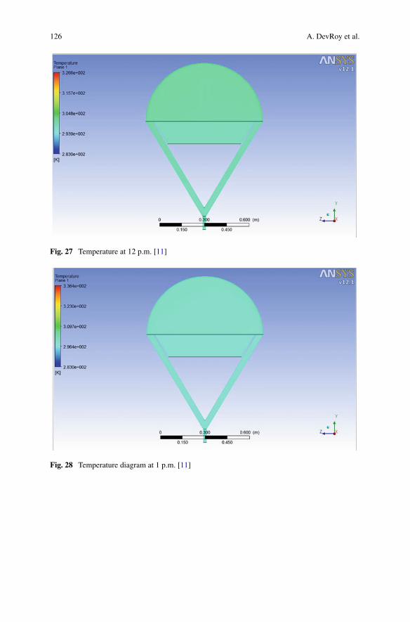
126 A. DevRoy et al.
Fig. 27 Temperature at 12 p.m. [11]
Fig. 28 Temperature diagram at 1 p.m. [11]
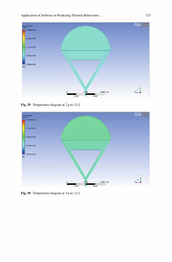
Application of Software in Predicting Thermal Behaviours … 127
Fig. 29 Temperature diagram at 2 p.m. [11]
Fig. 30 Temperature diagram at 3 p.m. [11]
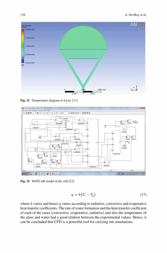
128 A. DevRoy et al.
Fig. 31 Temperature diagram at 4 p.m. [11]
Fig. 32 MATLAB model of the still [23]
q = h(Tv − Tg
)(17)
where h varies and hence q varies according to radiative, convective and evaporativeheat transfer coefficients. The rate of water formation and the heat transfer coefficientof each of the cases (convective, evaporative, radiative) and also the temperature ofthe glass and water had a good relation between the experimental values. Hence, itcan be concluded that CFD is a powerful tool for carrying out simulations.
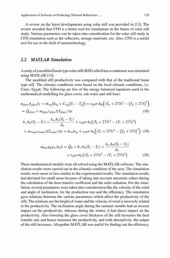
Application of Software in Predicting Thermal Behaviours … 129
A review on the latest developments using solar still was provided in [13]. Thereview revealed that CFD is a better tool for simulations in the future of solar stillstudy. Various parameters can be taken into consideration for the solar still study inCFD simulation such as the reflectors, storage materials, etc. Also, CFD is a usefultool for use in the field of nanotechnology.
2.2 MATLAB Simulation
Astudyof amodifiedbasin type solar still (BSS)whichhas a condenserwas simulatedusing MATLAB [14].
The modified still productivity was compared with that of the traditional basintype still. The climatic conditions were based on the local climatic conditions, i.e.Cairo, Egypt. The following are few of the energy balanced equations used in themathematical modelling for glass cover, salt water and still base:
αglassAglass IT + mwg(hfg + Cwg
(Tv − Tg
)) + εeffσ AB
((Tw + 273)4 − (
Tg + 273)4)
= Qglass + mglasscglass�Tglass/�t (18)
hvAb(Tb − Tv) + kwAb(Tb − Tv)
dw+ εeffσ Ab
((Tb + 273)4 − (Tv + 273)4
)
= mwatercwater�Twater/�t + mwthfg + εeffσ Ab
((Tv + 273)4 − (
Tg + 273)4)
(19)
αbaseϕgϕwAb It = Qb + hvAb(Tb − Tv) + kwAb(Tb − Tv)
dw+ εeffωAb
((Tb + 273)4 − (Tv + 273)4
)(20)
These mathematical models were all solved using the MATLAB software. The sim-ulation results were carried out in the climatic condition of the area. The simulationresults were more or less similar to the experimental results. The simulation resultshad deviated for small areas because of taking into account uncertain values duringthe calculation of the heat transfer coefficient and the solar radiation. For the simu-lation, several parameters were taken into consideration like the velocity of the windand angle of inclination. for the production rate and the efficiency. The simulationgave relations between the various parameters which affect the productivity of thestill. The relations are the height of water and the velocity of wind is inversely relatedto the productivity. The inclination angle during the summer months had an inverseimpact on the productivity, whereas during the winter, it had direct impact on theproductivity. Also lowering the glass cover thickness of the still increases the heattransfer rate and hence increases the productivity, and with absorptivity, the outputof the still increases. Altogether MATLAB was useful for finding out the efficiency,
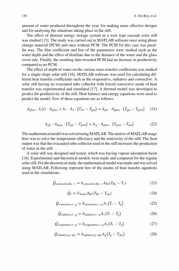
130 A. DevRoy et al.
amount of water produced throughout the year, for making more effective designsand for analysing the situations taking place in the still.
The effect of thermal energy storage system in a weir type cascade solar stillwas studied [15]. The study was carried out in MATLAB software once using phasechange material (PCM) and once without PCM. The PCM for this case was paraf-fin wax. The film coefficient and few of the parameters were studied such as thewater depth and the effect of distillate due to the distance of the water and the glasscover rate. Finally, the resulting data revealed PCM had an increase in productivitycompared to no PCM.
The effect of depth of water on the various mass transfer coefficients was studiedfor a single-slope solar still [16]. MATLAB software was used for calculating dif-ferent heat transfer coefficients such as the evaporative, radiative and convective. Asolar still having an evacuated tube collector with forced convective mode of heattransfer was experimented and simulated [17]. A thermal model was developed topredict the productivity of the still. Heat balance and energy equations were used topredict the model. Few of these equations are as follows:
αglass · Is(t) · Aglass + hv · Aa · (Tsw − Tgin
) = hglc · Aglass · (Tgin − Tgout
)(21)
hglc · Aglass · (Tgin − Tgout
) = h p · Aglass · (Tgout − Tam
)(22)
Themathematicalmodelwas solved usingMATLAB.Themotive ofMATLABusagehere was to solve the temperature efficiency and the emissivity of the still. The finaloutput was that the evacuated tube collector used in the still increases the productionof water in the still.
A solar still was designed and tested, which was having vapour adsorption basin[18]. Experimental and theoretical models were made and compared for the regularsolar still. For the theoretical study, themathematicalmodelwasmade andwas solvedusing MATLAB. Following represent few of the modes of heat transfer equationsused in the simulations.
Qconvective,Bs−v = hconvective,Bs−vABs(TBs − Tv) (23)
Ql = UbasinABs(TBs − Tam) (24)
Qconvective,v−g = hconvective,v−gAv(Tv − Tg
)(25)
Qradiative,v−g = hradiative,v−gAv(Tv − Tg
)(26)
Qevaporative,v−g = hevaporative,v−gAv(Tv − Tg
)(27)
Qradiative,g−sky = hradiative,g−skyAg(Tg − Tsky
)(28)
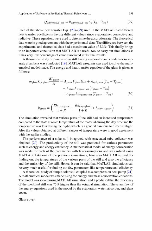
Application of Software in Predicting Thermal Behaviours … 131
Qconvective,g−sky = hconvective,g−skyAg(Tg − Tsky
)(29)
Each of the above heat transfer Eqs. (23)–(29) used in the MATLAB had differentheat transfer coefficients having different values since evaporative, convective andradiative. These equationswere used to determine the absorption rate. The theoreticaldata were in good agreement with the experimental data. The difference between theexperimental and theoretical data had a maximum value of 2.3%. This finally bringsto an important conclusion that MATLAB is a useful tool to carry out simulations asit has very low percentage of error associated in its final results.
A theoretical study of passive solar still having evaporator and condenser in sep-arate chambers was conducted [19]. MATLAB program was used to solve the math-ematical model made. The energy and heat transfer equation of the glass is given asfollows:
mglasscCp,glasscdTglasscdt
= AglasscFglasscGeff + Av1hglassc(Tv1 − Tglassc
)
− Aglasschc,glassc−am(Tglassc − Tam
)
− Aglasschrad,glassc−sky(Tglassc − Tsky
)(30)
hglassc =(Rhc,v1−glassc
1 + R+ Rhe,v1−glassc
1 + R+ hrad,v1−glassc
)(31)
The simulation revealed that various parts of the still had an increased temperaturecompared to the state at room temperature of the material during the day time and thetemperature was less during the night, which is a general case due to direct sunlight.Also the values obtained at different ranges of temperature were in good agreementwith the earlier studies.
The performance of a solar still integrated with evacuated tube collector wasobtained [20]. The productivity of the still was predicted for various parameterssuch as energy and energy efficiency. A mathematical model of energy conservationwas made for each of the parameters with few assumptions and was solved usingMATLAB. Like one of the previous simulations, here also MATLAB is used forfinding out the temperatures of the various parts of the still and also the efficiencyand the emissivity of the still. Hence, it can be said that MATLAB simulations canbe very much useful for finding out few parameters like temperature and efficiency.
A theoretical study of simple solar still coupled to a compression heat pump [21].A mathematical model was made using the energy and mass conservation equations.Themodel was solved usingMATLAB simulation, and it predicted that the efficiencyof the modified still was 75% higher than the original simulation. These are few ofthe energy equations used in the model by the evaporator, water, absorber, and glasscover.
Glass cover:
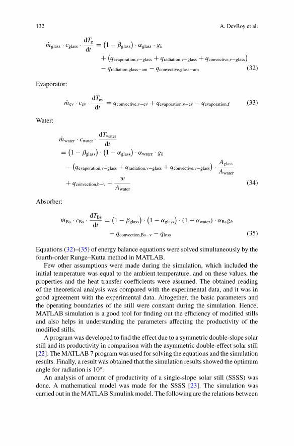
132 A. DevRoy et al.
mglass · cglass · dTgdt
= (1 − βglass
) · αglass · gh+ (
qevaporation,v−glass + qradiation,v−glass + qconvective,v−glass)
− qradiation,glass−am − qconvective,glass−am (32)
Evaporator:
mev · cev · dTevdt
= qconvective,v−ev + qevaporation,v−ev − qevaporation,f (33)
Water:
mwater · cwater · dTwaterdt
= (1 − βglass
) · (1 − αglass
) · αwater · gh− (
qevaporation,v−glass + qradiation,v−glass + qconvective,v−glass) · Aglass
Awater
+ qconvection,b−v + w
Awater(34)
Absorber:
mBs · cBs · dTBsdt
= (1 − βglass
) · (1 − αglass
) · (1 − αwater) · αBsgh
− qconvection,Bs−v − qloss (35)
Equations (32)–(35) of energy balance equations were solved simultaneously by thefourth-order Runge–Kutta method in MATLAB.
Few other assumptions were made during the simulation, which included theinitial temperature was equal to the ambient temperature, and on these values, theproperties and the heat transfer coefficients were assumed. The obtained readingof the theoretical analysis was compared with the experimental data, and it was ingood agreement with the experimental data. Altogether, the basic parameters andthe operating boundaries of the still were constant during the simulation. Hence,MATLAB simulation is a good tool for finding out the efficiency of modified stillsand also helps in understanding the parameters affecting the productivity of themodified stills.
A program was developed to find the effect due to a symmetric double-slope solarstill and its productivity in comparison with the asymmetric double-effect solar still[22]. TheMATLAB 7 programwas used for solving the equations and the simulationresults. Finally, a result was obtained that the simulation results showed the optimumangle for radiation is 10°.
An analysis of amount of productivity of a single-slope solar still (SSSS) wasdone. A mathematical model was made for the SSSS [23]. The simulation wascarried out in theMATLABSimulinkmodel. The following are the relations between
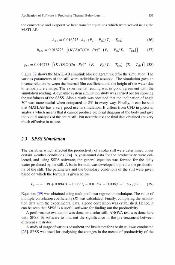
Application of Software in Predicting Thermal Behaviours … 133
the convective and evaporative heat transfer equations which were solved using theMATLAB:
he,v = 0.016273 · hc · (Pv − Pci)/Tv − Tgin) (36)
he,w = 0.016723 · [(K/A)C(Gn · Pr)n · (
Pv − Pci/Tv − Tgin)]
(37)
qe,v = 0.016273 · [(K/D)C(Gn · Pr)n · (
Pv − Pci/Tv − Tgin) · (
Tv − Tgin)]
(38)
Figure 32 shows the MATLAB simulink block diagram used for the simulation. Thevarious parameters of the still were individually assessed. The simulation gave aninverse relation between the internal film coefficient and the height of the water dueto temperature change. The experimental reading was in good agreement with thesimulation reading. A dynamic system simulation study was carried out for showingthe usefulness of the SSSS. Also a result was obtained that the inclination of angle30° was more useful when compared to 23° in every way. Finally, it can be saidthat MATLAB has a very good use in simulation. It differs from CFD in pictorialanalysis which means that it cannot produce pictorial diagram of the body and giveindividual analysis of the entire still, but nevertheless the final data obtained are verymuch effective in nature.
2.3 SPSS Simulation
The variables which affected the productivity of a solar still were determined undercertain weather conditions [24]. A year-round data for the productivity were col-lected, and using SSPS software, the general equation was formed for the dailywater produced by the still. A basic formula was developed to predict the productiv-ity of the still. The parameters and the boundary conditions of the still were givenbased on which the formula is given below:
Pd = −1.39 + 0.894H + 0.033ta − 0.017W − 0.008φ − 1.2(λ/ϕ) (39)
Equation (39) was obtained using multiple linear regression technique. The value ofmultiple correlation coefficients (R) was calculated. Finally, comparing the simula-tion data with the experimental data, a good correlation was established. Hence, itcan be seen that SPSS is a useful software for finding out the productivity.
A performance evaluation was done on a solar still. ANOVA test was done herewith SPSS 16 software to find out the significance in the pre-treatment betweendifferent substrates.
A study of usage of various adsorbent and insulators for a basin still was conducted[25]. SPSS was used for analysing the changes in the means of productivity of the
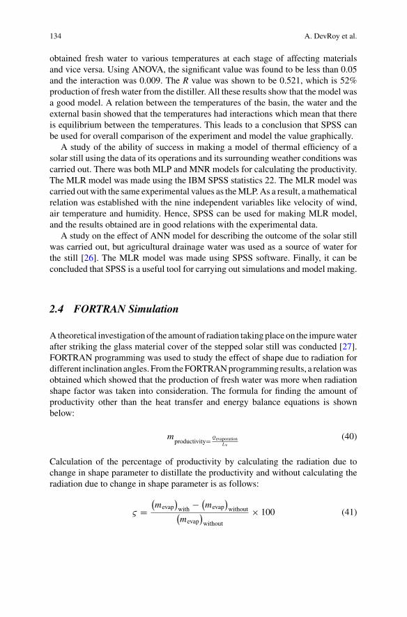
134 A. DevRoy et al.
obtained fresh water to various temperatures at each stage of affecting materialsand vice versa. Using ANOVA, the significant value was found to be less than 0.05and the interaction was 0.009. The R value was shown to be 0.521, which is 52%production of fresh water from the distiller. All these results show that the model wasa good model. A relation between the temperatures of the basin, the water and theexternal basin showed that the temperatures had interactions which mean that thereis equilibrium between the temperatures. This leads to a conclusion that SPSS canbe used for overall comparison of the experiment and model the value graphically.
A study of the ability of success in making a model of thermal efficiency of asolar still using the data of its operations and its surrounding weather conditions wascarried out. There was both MLP and MNR models for calculating the productivity.The MLR model was made using the IBM SPSS statistics 22. The MLR model wascarried out with the same experimental values as theMLP.As a result, amathematicalrelation was established with the nine independent variables like velocity of wind,air temperature and humidity. Hence, SPSS can be used for making MLR model,and the results obtained are in good relations with the experimental data.
A study on the effect of ANN model for describing the outcome of the solar stillwas carried out, but agricultural drainage water was used as a source of water forthe still [26]. The MLR model was made using SPSS software. Finally, it can beconcluded that SPSS is a useful tool for carrying out simulations and model making.
2.4 FORTRAN Simulation
Atheoretical investigation of the amount of radiation taking place on the impurewaterafter striking the glass material cover of the stepped solar still was conducted [27].FORTRAN programming was used to study the effect of shape due to radiation fordifferent inclination angles. From theFORTRANprogramming results, a relationwasobtained which showed that the production of fresh water was more when radiationshape factor was taken into consideration. The formula for finding the amount ofproductivity other than the heat transfer and energy balance equations is shownbelow:
mproductivity= Qevaporation
Lv
(40)
Calculation of the percentage of productivity by calculating the radiation due tochange in shape parameter to distillate the productivity and without calculating theradiation due to change in shape parameter is as follows:
ς =(mevap
)with − (
mevap)without(
mevap)without
× 100 (41)
Application of Software in Predicting Thermal Behaviours … 135
Finally, it can be concluded that FORTRAN programming is a useful to for findingout the effect due to individual parameters.
An experimental and mathematical study of the addition of solar reflector andcollector in a simple solar still (SSS) was conducted [28]. The mathematical modelin the form of differential equations was solved by the fourth-order Runge–Kuttamethod. The entire process is done in FORTRAN language. The program was alsoused to predict the changes in temperature per hour for the various parts of the solarstill and also to predict the amount of clean water obtained and the film coefficientof the still. The equation for the hourly yield is given below:
meva = Ueva · (Tv − Tgin
) · 3600/Lv (42)
Here Eq. (42) meva is the distillate rate and Lv is the latent heat of vaporization andUeva is the film coefficient due to evaporation. FORTRAN language can be used forsolvingmathematicalmodels predicting various outputs of the still. Hence, themodelobtained by the mathematical analysis had a good correlation with the experimentaldata obtained for the same experiment.
A comparative study on the effects of coupling flat plate and spherical plate solarstill collector was done. The thermal modelling differential equations were solvedusing the fourth-order Runge–Kutta method. Programming was done in FORTRANlanguage. This takes back to the previous conclusion that FORTRAN is a useful toolfor finding out the parameters.
A simulation study of the double-film solar still together with conventional solarstill was carried out [29]. The FORTRAN 90 was used for finding out the simu-lated values. The newly modified still was compared with the original solar still forassessment.
A study on the methods to increase the productivity of fresh water in a solar stillby changing glass screen design and amount of solar radiation absorbed between thesingle slopes and double slopes, hemispherical still was conducted [30]. A fourth-order Runge–Kutta was used for solving equations. The programs for finding outthe various parameters were made using FORTRAN language. Hence, based on theprevious analysis, a conclusion can be made that FORTRAN is one of the usefultools which is favoured for finding individualistic parameters.
A study of the ability of single and double stills to be used in the daily purpose foreconomic use and also the energy transfer processes of the stills and its surroundingswas carried out [31]. Heat and mass transfer equations were used for the modelling.The equations were fourth-order differential equations solved by using the methodof Runge–Kutta in FORTRAN language. The final results obtained were used foranalysis of the feasibility of the stills.
136 A. DevRoy et al.
2.5 MATLAB Simulation on Single-Stage Active Still
Studying of a single-slope solar still contains a fluid for supplying heat energy tothe liquid [32]. The energy equations were solved using the MATLAB model. TheMATLAB equation was based on the command ode 15s, which is faster than thecommand ode 45. The energy equations were generally the parameters of the stillssuch as inner glass cover and outer glass cover. The mass balance equations areillustrated below:
m ′SW = m ′
ev + m ′b (43)
m ′SWySW = m ′
byb (44)
m ′b = 1
χm ′
sw (45)
m ′ev = 1 − χ
χm ′
sw (46)
The simulation results gave a significant relation between the speed of the wind andits effect in the production of amount of distilled water. Also it showed that waterdepth had a significant relation with the production of fresh water.
ANN model was used to study the productivity of a triple-slope solar still [33].Three ANNmodels were made and solved using MATLABmodels such as the feed-back network model, the Elman model and the NARXmodel. For the NARXmodel,there was 3 types of neuron numbers, each created and solved using MATLAB. Thedata consisted of 46 samples, which were taken as input data for the ANN model.Finally, the results were that the feed-forward model had the best results comparedto the other two models.
An optimization of the number of collectors was done for PV/T hybrid solar still[34]. The software used was MATLAB 7 for solving the equations, few of whichwere involved of heat and mass transfer and energy equations. Finally, the hourlyvariations were found out.
A study of a modified still, which has three different designs of cover each havingdifferent amount of productivity, was done [35]. A MATLAB program was used fordevelopment of the model. Also the MATLAB program was used to find the variousrelations between the different parameters of the still. The result obtained was thatno model had a good output over the range of considered months on comparison.The result obtained by the MATLAB simulation was not in good agreement with theexperimental data due to the variation in parameters.
A study to find the inner and outer glass covers of an active solar still was con-ducted [36]. MATLAB program was used here in order to calculate the various filmcoefficients. Further, these values will be used for calculating the theoretical values
Application of Software in Predicting Thermal Behaviours … 137
of various parameters. From the above procedure, it can be said that MATLAB isuseful for making and validating experimental models.
2.6 FORTRAN Simulation of Active Solar Still
A study of a modified double-slope active solar still and a numerical investigation forthe still were carried out [37]. The numerical model was solved using FORTRAN 6.6computer program. The program solved energy equations of still such as the basin,water and cover of the still. All the main energy equations were solved using thefourth-order Runge–Kutta method. The final results of the simulation displayed therelation of the temperature effects and fresh water productivity.
2.7 CFD Simulation of Multistage Still
A CFD study on novel multistage evacuated solar still using FLUENT software wasconducted. The still consisted of three stages, but only one stage was taken for CFDsimulation. The model of the still had a finite element analysis (FEA) and a structuralanalysis using MSC/NASTRAN FEA software. The simulation was done in a 2Dmodel. The FLUENT segregated solver was used for solving the models of transientconditions.
The figures below illustrate the results obtained on CFD simulation.Figure 33 illustrates the stress conditions of the cylindrical model made after
stiffener was added to the walls of the model. Figure 34 shows the liquid mixture ofwater as a fraction of volume. It can be seen that the maximum liquid water is formedat the base of the still. The simulation result was very handful for the developmentand for implementing new designs. Hence, it can be concluded that CFD can be usednot only for comparison between experimental and theoretical analyses but also forfinding out the relation between various parameters.
A newmultistage solar still was designed for increasing the amount of fresh waterproduced and also to increase the efficiency over the conventional simple solar still[38]. CFD FLUENT software was used to find out the heat and mass transfer ratesof the still. The structure was made using NASTRAN software. The stage of thestill was modelled using the Gambit pre-processor. The mesh generated was 2D innature.
Figure 35 represents the overall density of the mixture of water in liquid phasein the simulation. The amount of condensation of water taken place inside the stillis shown in Fig. 36. As illustrated from the figure, the condensation is maximumwhere the evaporation occurs. Figure 37 illustrates the path motion of the vapourswhere the heavier vapours are moving down and the hot vapours are moving up.The big vortices are away from the smaller ones; also, it can be seen that they areall continuous in nature. Figure 38 illustrates the velocity vectors of the path taken
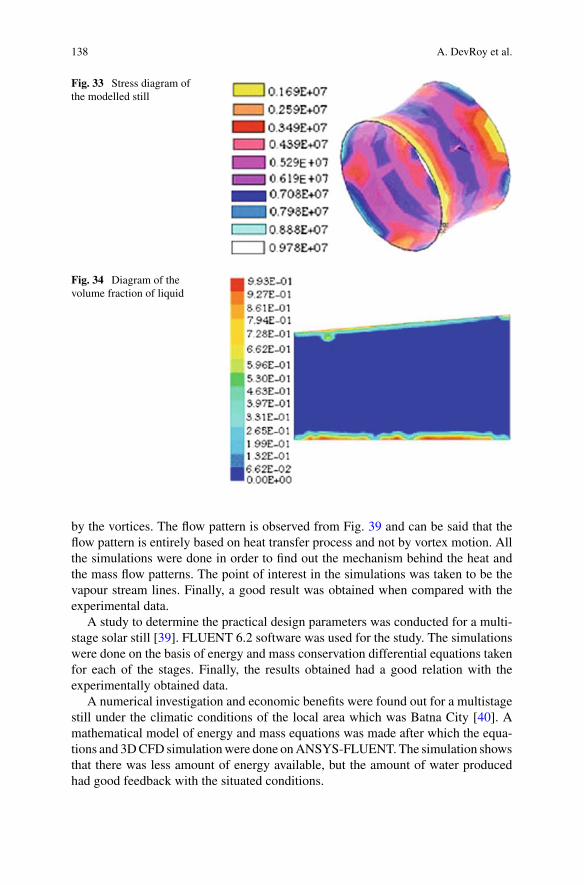
138 A. DevRoy et al.
Fig. 33 Stress diagram ofthe modelled still
Fig. 34 Diagram of thevolume fraction of liquid
by the vortices. The flow pattern is observed from Fig. 39 and can be said that theflow pattern is entirely based on heat transfer process and not by vortex motion. Allthe simulations were done in order to find out the mechanism behind the heat andthe mass flow patterns. The point of interest in the simulations was taken to be thevapour stream lines. Finally, a good result was obtained when compared with theexperimental data.
A study to determine the practical design parameters was conducted for a multi-stage solar still [39]. FLUENT 6.2 software was used for the study. The simulationswere done on the basis of energy and mass conservation differential equations takenfor each of the stages. Finally, the results obtained had a good relation with theexperimentally obtained data.
A numerical investigation and economic benefits were found out for a multistagestill under the climatic conditions of the local area which was Batna City [40]. Amathematical model of energy and mass equations was made after which the equa-tions and 3DCFD simulationwere done onANSYS-FLUENT. The simulation showsthat there was less amount of energy available, but the amount of water producedhad good feedback with the situated conditions.
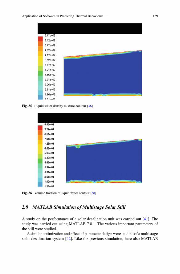
Application of Software in Predicting Thermal Behaviours … 139
Fig. 35 Liquid water density mixture contour [38]
Fig. 36 Volume fraction of liquid water contour [38]
2.8 MATLAB Simulation of Multistage Solar Still
A study on the performance of a solar desalination unit was carried out [41]. Thestudy was carried out using MATLAB 7.0.1. The various important parameters ofthe still were studied.
A similar optimization and effect of parameter designwere studied of amultistagesolar desalination system [42]. Like the previous simulation, here also MATLAB
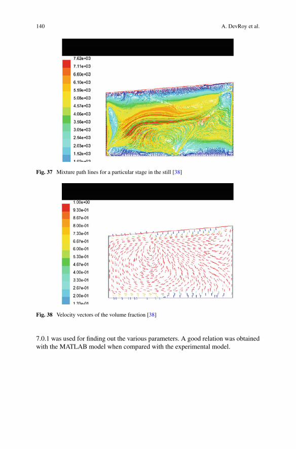
140 A. DevRoy et al.
Fig. 37 Mixture path lines for a particular stage in the still [38]
Fig. 38 Velocity vectors of the volume fraction [38]
7.0.1 was used for finding out the various parameters. A good relation was obtainedwith the MATLAB model when compared with the experimental model.
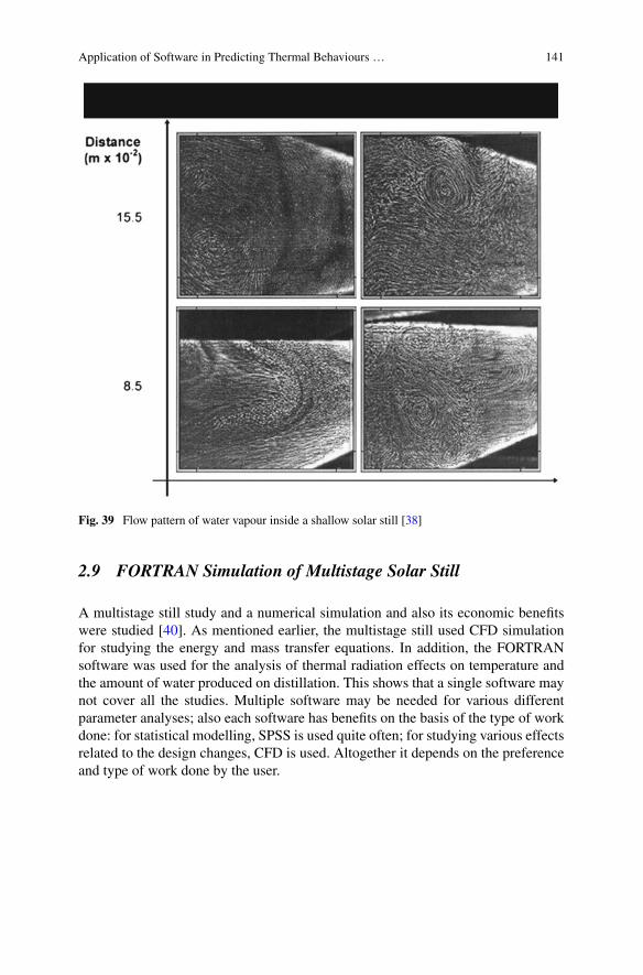
Application of Software in Predicting Thermal Behaviours … 141
Fig. 39 Flow pattern of water vapour inside a shallow solar still [38]
2.9 FORTRAN Simulation of Multistage Solar Still
A multistage still study and a numerical simulation and also its economic benefitswere studied [40]. As mentioned earlier, the multistage still used CFD simulationfor studying the energy and mass transfer equations. In addition, the FORTRANsoftware was used for the analysis of thermal radiation effects on temperature andthe amount of water produced on distillation. This shows that a single software maynot cover all the studies. Multiple software may be needed for various differentparameter analyses; also each software has benefits on the basis of the type of workdone: for statistical modelling, SPSS is used quite often; for studying various effectsrelated to the design changes, CFD is used. Altogether it depends on the preferenceand type of work done by the user.
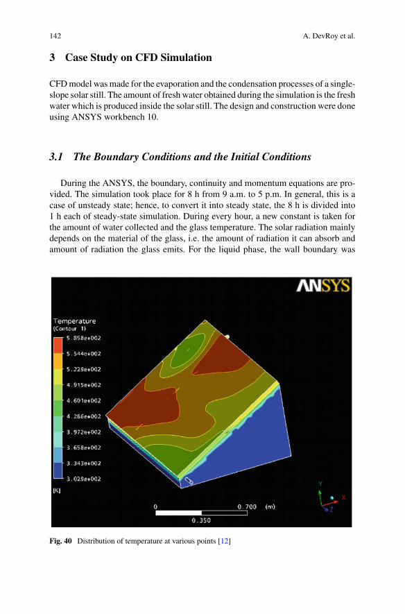
142 A. DevRoy et al.
3 Case Study on CFD Simulation
CFDmodel wasmade for the evaporation and the condensation processes of a single-slope solar still. The amount of fresh water obtained during the simulation is the freshwater which is produced inside the solar still. The design and construction were doneusing ANSYS workbench 10.
3.1 The Boundary Conditions and the Initial Conditions
During the ANSYS, the boundary, continuity and momentum equations are pro-vided. The simulation took place for 8 h from 9 a.m. to 5 p.m. In general, this is acase of unsteady state; hence, to convert it into steady state, the 8 h is divided into1 h each of steady-state simulation. During every hour, a new constant is taken forthe amount of water collected and the glass temperature. The solar radiation mainlydepends on the material of the glass, i.e. the amount of radiation it can absorb andamount of radiation the glass emits. For the liquid phase, the wall boundary was
Fig. 40 Distribution of temperature at various points [12]
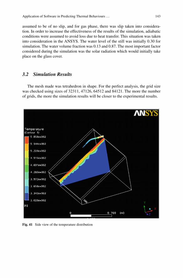
Application of Software in Predicting Thermal Behaviours … 143
assumed to be of no slip, and for gas phase, there was slip taken into considera-tion. In order to increase the effectiveness of the results of the simulation, adiabaticconditions were assumed to avoid loss due to heat transfer. This situation was takeninto consideration in the ANSYS. The water level of the still was initially 0.30 forsimulation. The water volume fraction was 0.13 and 0.87. The most important factorconsidered during the simulation was the solar radiation which would initially takeplace on the glass cover.
3.2 Simulation Results
The mesh made was tetrahedron in shape. For the perfect analysis, the grid sizewas checked using sizes of 32311, 47126, 64512 and 84121. The more the numberof grids, the more the simulation results will be closer to the experimental results.
Fig. 41 Side view of the temperature distribution
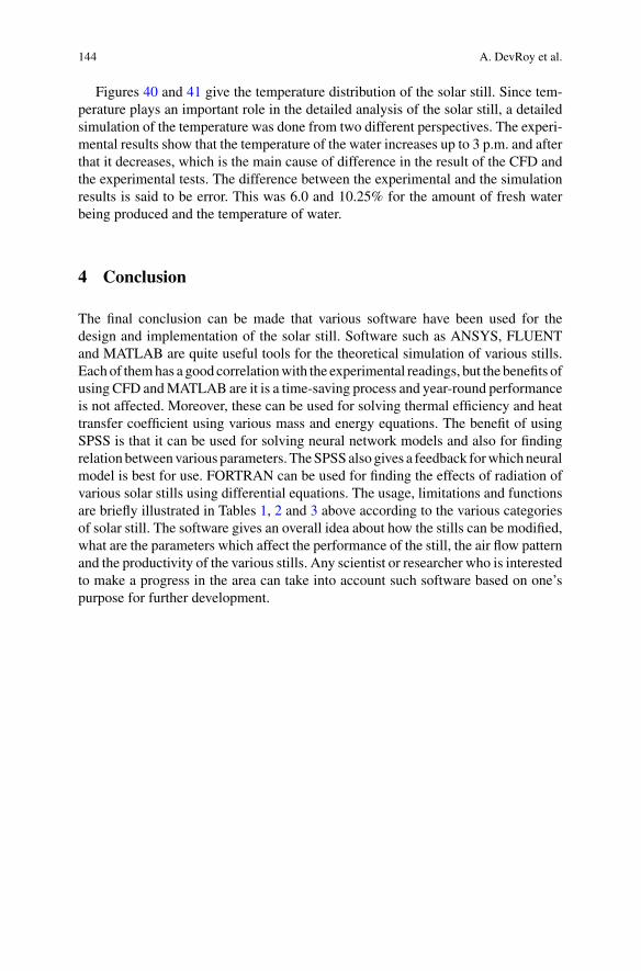
144 A. DevRoy et al.
Figures 40 and 41 give the temperature distribution of the solar still. Since tem-perature plays an important role in the detailed analysis of the solar still, a detailedsimulation of the temperature was done from two different perspectives. The experi-mental results show that the temperature of the water increases up to 3 p.m. and afterthat it decreases, which is the main cause of difference in the result of the CFD andthe experimental tests. The difference between the experimental and the simulationresults is said to be error. This was 6.0 and 10.25% for the amount of fresh waterbeing produced and the temperature of water.
4 Conclusion
The final conclusion can be made that various software have been used for thedesign and implementation of the solar still. Software such as ANSYS, FLUENTand MATLAB are quite useful tools for the theoretical simulation of various stills.Each of themhas a good correlationwith the experimental readings, but the benefits ofusing CFD andMATLAB are it is a time-saving process and year-round performanceis not affected. Moreover, these can be used for solving thermal efficiency and heattransfer coefficient using various mass and energy equations. The benefit of usingSPSS is that it can be used for solving neural network models and also for findingrelation betweenvarious parameters. TheSPSSalso gives a feedback forwhichneuralmodel is best for use. FORTRAN can be used for finding the effects of radiation ofvarious solar stills using differential equations. The usage, limitations and functionsare briefly illustrated in Tables 1, 2 and 3 above according to the various categoriesof solar still. The software gives an overall idea about how the stills can be modified,what are the parameters which affect the performance of the still, the air flow patternand the productivity of the various stills. Any scientist or researcher who is interestedto make a progress in the area can take into account such software based on one’spurpose for further development.
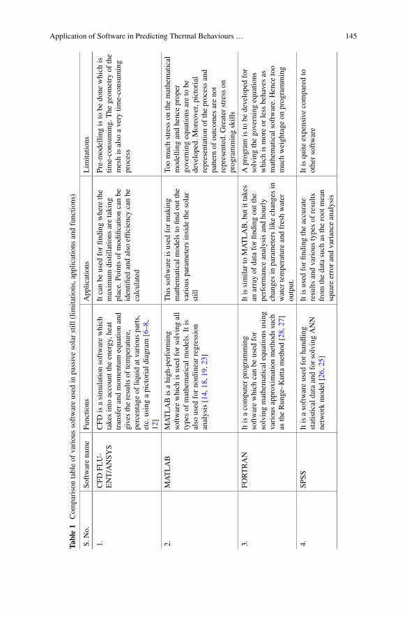
Application of Software in Predicting Thermal Behaviours … 145
Table1
Com
parisontableof
variou
ssoftwareused
inpassivesolarstill
(lim
itatio
ns,app
lications
andfunctio
ns)
S.No.
Softwarename
Functio
nsApp
lications
Lim
itatio
ns
1.CFD
FLU-
ENT/ANSY
SCFD
isasimulationsoftwarewhich
takesinto
accountthe
energy,h
eat
transfer
andmom
entum
equatio
nand
givestheresults
oftemperature,
percentage
ofliq
uidatvariousparts,
etc.usingapictoriald
iagram
[6–8,
12]
Itcanbe
used
forfin
ding
where
the
maxim
umdistillations
aretaking
place.Po
intsof
mod
ificatio
ncanbe
identifi
edandalso
effic
iencycanbe
calculated
Pre-modellin
gisto
bedone
which
istim
e-consum
ing.
The
geom
etry
ofthe
meshisalso
avery
time-consum
ing
process
2.MATLAB
MATLABisahigh-perform
ing
softwarewhich
isused
forsolvingall
typesof
mathematicalmod
els.Itis
also
used
fornonlinearregression
analysis[14,
18,1
9,23]
Thissoftwareisused
formaking
mathematicalmod
elsto
findou
tthe
variousparametersinside
thesolar
still
Toomuchstress
onthemathematical
modellin
gandhenceproper
governingequatio
nsareto
bedeveloped.
Moreover,pictorial
representatio
nof
theprocessand
pattern
ofoutcom
esarenot
represented.
Greater
stress
onprogrammingskills
3.FO
RTRAN
Itisacomputerprogramming
softwarewhich
canbe
used
for
solvingmathematicalequatio
nsusing
variousapproxim
ationmethods
such
astheRunge–K
uttamethod[28,
27]
Itissimila
rto
MATLAB,but
ittakes
anarrayof
dataforfin
ding
outthe
performance
analysisandhourly
changesin
parameterslik
echangesin
water
temperature
andfreshwater
output.
Aprogram
isto
bedevelopedfor
solvingthegoverningequatio
nswhich
ismoreor
less
behavesas
mathematicalsoftware.Hence
too
muchweightage
onprogramming
4.SP
SSItisasoftwareused
forhandlin
gstatistic
aldataandforsolvingANN
networkmodel[26,
25]
Itisused
forfin
ding
theaccurate
results
andvarioustypesof
results
from
thedatasuch
astheroot
mean
square
errorandvariance
analysis
Itisquite
expensivecomparedto
othersoftware
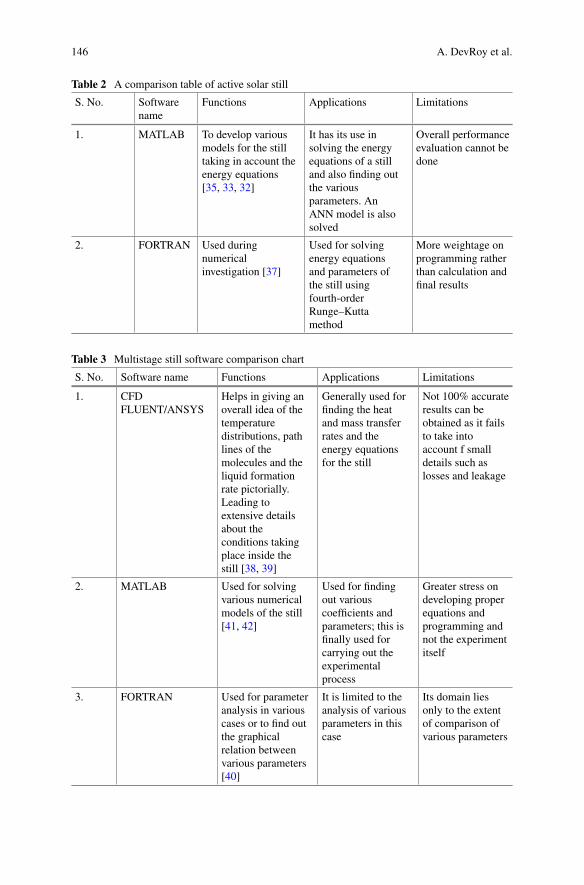
146 A. DevRoy et al.
Table 2 A comparison table of active solar still
S. No. Softwarename
Functions Applications Limitations
1. MATLAB To develop variousmodels for the stilltaking in account theenergy equations[35, 33, 32]
It has its use insolving the energyequations of a stilland also finding outthe variousparameters. AnANN model is alsosolved
Overall performanceevaluation cannot bedone
2. FORTRAN Used duringnumericalinvestigation [37]
Used for solvingenergy equationsand parameters ofthe still usingfourth-orderRunge–Kuttamethod
More weightage onprogramming ratherthan calculation andfinal results
Table 3 Multistage still software comparison chart
S. No. Software name Functions Applications Limitations
1. CFDFLUENT/ANSYS
Helps in giving anoverall idea of thetemperaturedistributions, pathlines of themolecules and theliquid formationrate pictorially.Leading toextensive detailsabout theconditions takingplace inside thestill [38, 39]
Generally used forfinding the heatand mass transferrates and theenergy equationsfor the still
Not 100% accurateresults can beobtained as it failsto take intoaccount f smalldetails such aslosses and leakage
2. MATLAB Used for solvingvarious numericalmodels of the still[41, 42]
Used for findingout variouscoefficients andparameters; this isfinally used forcarrying out theexperimentalprocess
Greater stress ondeveloping properequations andprogramming andnot the experimentitself
3. FORTRAN Used for parameteranalysis in variouscases or to find outthe graphicalrelation betweenvarious parameters[40]
It is limited to theanalysis of variousparameters in thiscase
Its domain liesonly to the extentof comparison ofvarious parameters
Application of Software in Predicting Thermal Behaviours … 147
References
1. Williams R (1960) Becquerel photovoltaic effect in binary compounds. J Chem Phys32(5):1505–1514
2. Tiwari GN, Singh HN, Tripathi R (2003) Present status of solar distillation. Sol Energy75(5):367–373
3. Panchal H, Patel P, Mevada R, Patel H (2014) Reviews on different energy absorbing materialsfor performance analysis of solar still. Int J Adv Eng Res Dev 1(11):62–66
4. Vishwanath Kumar P, Kumar A, Prakash O, Kaviti AK (2015) Solar stills system design: areview. Renew Sustain Energy Rev 51:153–181
5. Arulanandam SJ, Hollands KGT, Brundrett E (1999) A CFD heat transfer analysis of thetranspired solar collector under no-wind conditions. Sol Energy 67:93–100
6. Rahbar N, Esfahani JA (2012) Estimation of convective heat transfer coefficient in a single-slope solar still: a numerical study. Desalin Water Treat 50(1–3):387–396
7. Edalatpour M, Kianifar A, Ghiami S (2015) Effect of blade installation on heat transfer andfluid flow within a single slope solar still. Int Commun Heat Mass Transf 66:63–70
8. SetoodehN, Rahimi R,Ameri A (2011)Modeling and determination of heat transfer coefficientin a basin solar still using CFD. Desalination 268(1–3):103–110
9. Rahbar N, Esfahani JA, Fotouhi-Bafghi E (2015) Estimation of convective heat transfer coeffi-cient and water-productivity in a tubular solar still—CFD simulation and theoretical analysis.Sol Energy 113:313–323
10. Poullikkas A, Rouvas C, Hadjipaschalis I, Kourtis G (2012) Optimum sizing of steam turbinesfor concentrated solar power plants. Int J Energy Environ 3(1):9–18
11. Panchal HN, Shah PK (2013) Modeling and verification of hemispherical solar still usingANSYS CFD. Int J Energy Environ 4(3):2076–2909
12. Panchal HN, Shah PK (2011) Modelling and verification of single slope solar still usingANSYS-CFX. Int J Energy Environ 2(6):985–998
13. Edalatpour M, Aryana K, Kianifar A, Tiwari GN, Mahian O, Wongwises S (2016) Solar stills:a review of the latest developments in numerical simulations. Sol Energy 135:897–922
14. Ibrahim AGM, Elshamarka SE (2015) Performance study of a modified basin type solar still.Sol Energy 118:397–409
15. Tabrizi FF, Dashtban M, Moghaddam H (2010) Experimental investigation of a weir-typecascade solar still with built-in latent heat thermal energy storage system. Desalination260(1–3):248–253
16. Tiwari AK, Tiwari GN (2006) Effect of water depths on heat and mass transfer in a passivesolar still: in summer climatic condition. Desalination 195(1–3):78–94
17. Kumar S, Dubey A, Tiwari GN (2014) A solar still augmented with an evacuated tube collectorin forced mode. Desalination 347:15–24
18. Kannan R, Selvaganesan C, Vignesh M, Ramesh Babu B, Fuentes M, Vivar M, Skryabin I,Srithar K (2014) Solar still with vapor adsorption basin: performance analysis. Renew Energy62:258–264
19. Madhlopa A, Johnstone C (2009) Numerical study of a passive solar still with separate con-denser. Renew Energy 34(7):1668–1677
20. Singh RV, Kumar S, Hasan MM, Emran Khan M, Tiwari GN (2013) Performance of a solarstill integrated with evacuated tube collector in natural mode. Desalination 318:25–33
21. Halima HB, Frikha N, Slama RB (2014) Numerical investigation of a simple solar still coupledto a compression heat pump. Desalination 337(1):60–66
22. Abderachid T, Abdenacer K (2013) Effect of orientation on the performance of a symmetricsolar still with a double effect solar still (comparison study). Desalination 329:68–77
23. Kumar D, Himanshu P, Ahmad Z (2013) Performance analysis of single slope solar still. Int JMech Robot Res 3(3):66–72
24. Nafey AS, Abdelkader M, Abdelmotalip A, Mabrouk AA (2000) Parameters affecting solarstill productivity. Energy Convers Manag 41(16):1797–1809
148 A. DevRoy et al.
25. Burbano AM (2014) Evaluation of basin and insulating materials in solar still prototype forsolar distillation plant at Kamusuchiwo community, HighGuajira keywords building prototypestill. Int Conf Renew Energies Power Qual 1(12):547–552
26. Mashaly AF, Alazba AA (2016) Neural network approach for predicting solar still productionusing agricultural drainage as a feedwater source. Desalin Water Treat 57(59):28646–28660
27. El-Samadony YAF, El-Maghlany WM, Kabeel AE (2016) Influence of glass cover inclinationangle on radiation heat transfer rate within stepped solar still. Desalination 384:68–77
28. Karroute S, Chaker A (2014) Theoretical and numerical study of the effect of coupling acollector and reflector on the solar still efficiency. In: IREC 2014—5th international renewableenergy congress
29. Belhadj MM, Bouguettaia H, Marif Y, Zerrouki M (2015) Numerical study of a double-slopesolar still coupled with capillary film condenser in South Algeria. Energy Convers Manag94:245–252
30. Karroute S, Chaker A (2011) Effect of orientation of solar still on the productivity of freshwater. In: Revue des Energies Renouvelables ICESD’11 Adrar (2011), pp 25–31
31. Agboola OP, Atikol U, Assefi Hossein (2015) Feasibility assessment of basin solar stills. Int JGreen Energy 12(2):139–147
32. Hamadou OA, Abdellatif K (2014) Modeling an active solar still for sea water desalinationprocess optimization. Desalination 354:1–8
33. Hamdan MA, Haj Khalil RA, Abdelhafez EAM (2013) Comparison of neural network modelsin the estimation of the performance of solar still under Jordanian climate. J Clean EnergyTechnol 1(3):239–242
34. Gaur MK, Tiwari GN (2010) Optimization of number of collectors for integrated PV/T hybridactive solar still. Appl Energy 87(5):1763–1772
35. Malaeb L, Ayoub GM, Al-Hindi M (2014) The effect of cover geometry on the productivity ofa modified solar still desalination unit. Energy Procedia 50:406–413
36. Dimri V, Sarkar B, Singh U, Tiwari GN (2008) Effect of condensing cover material on yieldof an active solar still: an experimental validation. Desalination 227(1–3):178–189
37. Bait O, Si-ameur M, Benmoussa A (2015) Numerical approach of a double slope solar stillcombined with a cylindrical solar water heater: mass and heat energy balance mathematicalmodel. J Polytechnic-Politeknik Dergisi 18(4):227–234
38. Ahmed MI, Hrairi M, Ismail AF (2009) On the characteristics of multistage evacuated solardistillation. Renew Energy 34(6):1471–1478
39. Shatat MIM, Mahkamov K (2010) Determination of rational design parameters of a multi-stage solar water desalination still using transient mathematical modelling. Renew Energy35(1):52–61
40. Bait O, Si-AmeurM (2016) Numerical investigation of a multi-stage solar still under Batna cli-matic conditions: effect of radiation termonmass and heat energy balances. Energy 98:308–323
41. Reddy KS, Ravi Kumar K, O’Donovan TS, Mallick TK (2012) Performance analysis of anevacuated multi-stage solar water desalination system. Desalination 288:80–92
42. Kumar PV, Kaviti AK, Prakash O, Reddy KS (2012) Optimization of design and operatingparameters on the year round performance of a multi-stage evacuated solar desalination systemusing transient mathematical analysis. Int J Energy Environ 3(3):409–434
43. Kabeel AE, Omara ZM, Essa FA, Abdullah AS (2016) Solar still with condenser—a detailedreview. Renew Sustain Energy Rev 59:839–857
44. Saidur R, Elcevvadi ET,Mekhilef S, Safari A,MohammedHA (2011) An overview of differentdistillation methods for small scale applications. Renew Sustain Energy Rev 15(9):4756–4764
45. Rajaseenivasan T, Kalidasa Murugavel K, Elango T, Samuel Hansen R (2013) A review ofdifferent methods to enhance the productivity of the multi-effect solar still. Renew SustainEnergy Rev 17:248–259
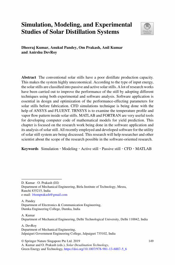
Simulation, Modeling, and ExperimentalStudies of Solar Distillation Systems
Dheeraj Kumar, Anukul Pandey, Om Prakash, Anil Kumarand Anirshu DevRoy
Abstract The conventional solar stills have a poor distillate production capacity.This makes the system highly uneconomical. According to the type of input energy,the solar stills are classified into passive and active solar stills. A lot of researchworkshave been carried out to improve the performance of the still by adopting differenttechniques using both experimental and software analysis. Software application isessential in design and optimization of the performance-effecting parameters forsolar stills before fabrication. CFD simulations technique is being done with thehelp of ANSYS and FLUENT. TRNSYS is to examine the temperature profile andvapor flow pattern inside solar stills. MATLAB and FORTRAN are very useful toolsfor developing computer code of mathematical models for yield prediction. Thischapter is focused on the research work being done in the software application andits analysis of solar still. All recently employed and developed software for the utilityof solar still system are being discussed. This research will help researcher and otherscientist about the scope of the research possible in the software-oriented research.
Keywords Simulation · Modeling · Active still · Passive still · CFD · MATLAB
D. Kumar · O. Prakash (B)Department of Mechanical Engineering, Birla Institute of Technology, Mesra,Ranchi 835215, Indiae-mail: [email protected]
A. PandeyDepartment of Electronics & Communication Engineering,Dumka Engineering College, Dumka, India
A. KumarDepartment of Mechanical Engineering, Delhi Technological University, Delhi 110042, India
A. DevRoyDepartment of Mechanical Engineering,Jalpaiguri Government Engineering College, Jalpaiguri 735102, India
© Springer Nature Singapore Pte Ltd. 2019A. Kumar and O. Prakash (eds.), Solar Desalination Technology,Green Energy and Technology, https://doi.org/10.1007/978-981-13-6887-5_6
149
150 D. Kumar et al.
1 Introduction
Solar energy is an inexhaustible source of energy, available in abundance and ispollution free. Everyday earth receives plenty of energy from the sun. Solar distil-lation is one of the methods to extract drinkable water from saline water with thehelp of solar radiation. Solar still works on the principle of solar distillation and pro-vides potable water for direct human consumption. This distillation process is basedon the evaporation and condensation phenomenon. Using commercial methods toextract pure water via distillation in remote areas is not feasible as the availabilityof fossil fuel or electricity is limited in those areas, and total cost of the system isvery high [1]. Therefore, to provide clean water in remote villages, solar still hasemerged as the most effective alternative. Solar radiation is used to heat up the stillbasin water, which leads to evaporation of basin water. By this, evaporated vaporcondenses on inner glass cover surface. The collected distillate output through thecollecting channel is the fresh water.
Solar stills are available in the large variety depending upon their mode of oper-ation as an active or passive mode. For the better performance, it is needed to doa parametric evaluation and its analysis. The design of solar still can be optimizedwith the help of relevant software. Computational fluid dynamics (CFD) analyze andinvestigate the flow pattern of moist air and temperature distribution, stress patternof adjacent wall, and humid zone. CFD-based simulation software is also being usedfor the prediction of behavior of flow pattern near wall, and condensing cover. TheCFD simulation shows the zones where in solar still where condensation and evapo-ration occurs like moisture zone, condensing zone, evaporation zone, etc. [2]. It alsogives the information regarding the temperature of glass cover, water temperature,and vapor temperature, etc. Programming languages such as FORTRAN are beingused in simulation process for the solution of energy balance equations. ComsolMultiphysics coding is also used for numerical simulations for solar still. MATLABis an essential tool used for the development of mathematical models and to predictthe performance.
This chapter provides the information of the existing design software applied insolar still system for simulation procedures and optimization techniques. The flowbehavior, velocity pattern, and operating parameters effects on distillation rate. Theeffects of inclination angle and shear stress analyzation near wall are also being dis-cussed for different types of solar stills. The relevant data regarding vapor zones, shearstress zones, condensation zone, and its temperatures ranges are taken in account dur-ing analysis.
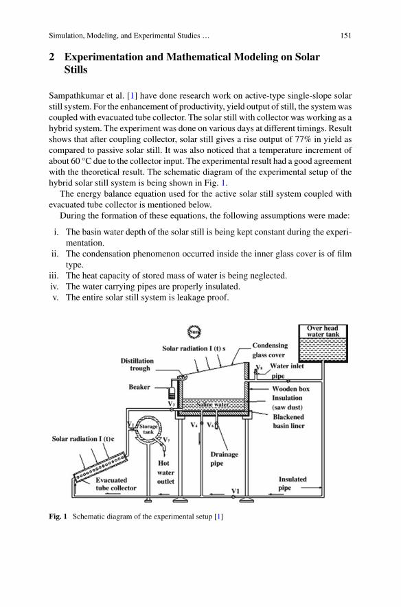
Simulation, Modeling, and Experimental Studies … 151
2 Experimentation and Mathematical Modeling on SolarStills
Sampathkumar et al. [1] have done research work on active-type single-slope solarstill system. For the enhancement of productivity, yield output of still, the systemwascoupled with evacuated tube collector. The solar still with collector was working as ahybrid system. The experiment was done on various days at different timings. Resultshows that after coupling collector, solar still gives a rise output of 77% in yield ascompared to passive solar still. It was also noticed that a temperature increment ofabout 60 °C due to the collector input. The experimental result had a good agreementwith the theoretical result. The schematic diagram of the experimental setup of thehybrid solar still system is being shown in Fig. 1.
The energy balance equation used for the active solar still system coupled withevacuated tube collector is mentioned below.
During the formation of these equations, the following assumptions were made:
i. The basin water depth of the solar still is being kept constant during the experi-mentation.
ii. The condensation phenomenon occurred inside the inner glass cover is of filmtype.
iii. The heat capacity of stored mass of water is being neglected.iv. The water carrying pipes are properly insulated.v. The entire solar still system is leakage proof.
Fig. 1 Schematic diagram of the experimental setup [1]
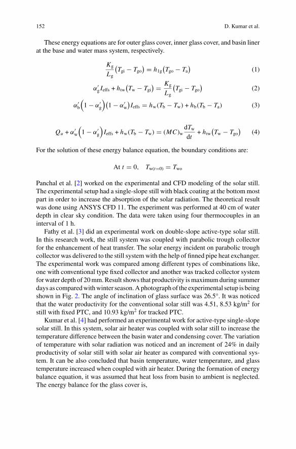
152 D. Kumar et al.
These energy equations are for outer glass cover, inner glass cover, and basin linerat the base and water mass system, respectively.
Kg
Lg
(Tgi − Tgo
) � h1g(Tgo − Ta
)(1)
α′g Ieffs + htw
(Tw − Tgi
) � Kg
Lg
(Tgi − Tgo
)(2)
α′b
(1 − α′
g
)(1 − α′
w
)Ieffs � hw(Tb − Tw) + hb(Tb − Ta) (3)
Qu + α′w
(1 − α′
g
)Ieffs + hw(Tb − Tw) � (MC)w
dTwdt
+ htw(Tw − Tgo
)(4)
For the solution of these energy balance equation, the boundary conditions are:
At t � 0, Tw(t�0) � Two
Panchal et al. [2] worked on the experimental and CFD modeling of the solar still.The experimental setup had a single-slope still with black coating at the bottommostpart in order to increase the absorption of the solar radiation. The theoretical resultwas done using ANSYS CFD 11. The experiment was performed at 40 cm of waterdepth in clear sky condition. The data were taken using four thermocouples in aninterval of 1 h.
Fathy et al. [3] did an experimental work on double-slope active-type solar still.In this research work, the still system was coupled with parabolic trough collectorfor the enhancement of heat transfer. The solar energy incident on parabolic troughcollector was delivered to the still systemwith the help of finned pipe heat exchanger.The experimental work was compared among different types of combinations like,one with conventional type fixed collector and another was tracked collector systemforwater depth of 20mm.Result shows that productivity ismaximumduring summerdays as comparedwithwinter season.Aphotographof the experimental setup is beingshown in Fig. 2. The angle of inclination of glass surface was 26.5°. It was noticedthat the water productivity for the conventional solar still was 4.51, 8.53 kg/m2 forstill with fixed PTC, and 10.93 kg/m2 for tracked PTC.
Kumar et al. [4] had performed an experimental work for active-type single-slopesolar still. In this system, solar air heater was coupled with solar still to increase thetemperature difference between the basin water and condensing cover. The variationof temperature with solar radiation was noticed and an increment of 24% in dailyproductivity of solar still with solar air heater as compared with conventional sys-tem. It can be also concluded that basin temperature, water temperature, and glasstemperature increased when coupled with air heater. During the formation of energybalance equation, it was assumed that heat loss from basin to ambient is neglected.The energy balance for the glass cover is,
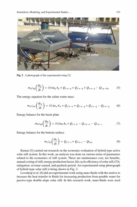
Simulation, Modeling, and Experimental Studies … 153
Fig. 2 A photograph of the experimental setup [3]
mgcpg
(dtgdt
)� I (t)αgAg + Qc,w−g + Qr,w−g + Qe,w−g − Qr,g−sky (5)
The energy equation for the saline water mass
mwcpw
(dtwdt
)� I (t)αwAw + Qc,b−w + Qc,w−g + Qr,w−g − Qe,w−g (6)
Energy balance for the basin plate
mbcpb
(dtbdt
)� I (t)αbAb + Qc,f−b − Qc,b−w − Qr,b−s (7)
Energy balance for the bottom surface
mscps
(dtsdt
)� Qc,f−s + Qr,b−s − Qloss (8)
Kumar [5] carried out research on the economic evaluation of hybrid-type activesolar still system. In this work, an analysis was done on various terms of parametersrelated to the economics of still system. These are maintenance cost, tax benefits,annual costing of still, energy production factor, life cycle efficiency of solar still, CO2
mitigation, revenue earned, and payback period. An experimental setup photographof hybrid-type solar still is being shown in Fig. 3.
Lovedeep et al. [6] did an experimental work using nano-fluids with the motive toincrease the heat transfer in fluids for increasing production from potable water forpassive-type double-slope solar still. In this research work, nano-fluids were used
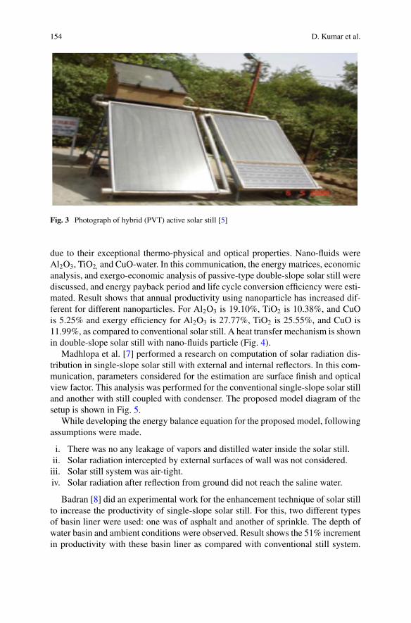
154 D. Kumar et al.
Fig. 3 Photograph of hybrid (PVT) active solar still [5]
due to their exceptional thermo-physical and optical properties. Nano-fluids wereAl2O3, TiO2, and CuO-water. In this communication, the energy matrices, economicanalysis, and exergo-economic analysis of passive-type double-slope solar still werediscussed, and energy payback period and life cycle conversion efficiency were esti-mated. Result shows that annual productivity using nanoparticle has increased dif-ferent for different nanoparticles. For Al2O3 is 19.10%, TiO2 is 10.38%, and CuOis 5.25% and exergy efficiency for Al2O3 is 27.77%, TiO2 is 25.55%, and CuO is11.99%, as compared to conventional solar still. A heat transfer mechanism is shownin double-slope solar still with nano-fluids particle (Fig. 4).
Madhlopa et al. [7] performed a research on computation of solar radiation dis-tribution in single-slope solar still with external and internal reflectors. In this com-munication, parameters considered for the estimation are surface finish and opticalview factor. This analysis was performed for the conventional single-slope solar stilland another with still coupled with condenser. The proposed model diagram of thesetup is shown in Fig. 5.
While developing the energy balance equation for the proposed model, followingassumptions were made.
i. There was no any leakage of vapors and distilled water inside the solar still.ii. Solar radiation intercepted by external surfaces of wall was not considered.iii. Solar still system was air-tight.iv. Solar radiation after reflection from ground did not reach the saline water.
Badran [8] did an experimental work for the enhancement technique of solar stillto increase the productivity of single-slope solar still. For this, two different typesof basin liner were used: one was of asphalt and another of sprinkle. The depth ofwater basin and ambient conditions were observed. Result shows the 51% incrementin productivity with these basin liner as compared with conventional still system.
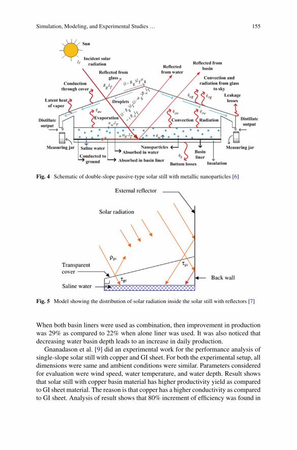
Simulation, Modeling, and Experimental Studies … 155
Fig. 4 Schematic of double-slope passive-type solar still with metallic nanoparticles [6]
Fig. 5 Model showing the distribution of solar radiation inside the solar still with reflectors [7]
When both basin liners were used as combination, then improvement in productionwas 29% as compared to 22% when alone liner was used. It was also noticed thatdecreasing water basin depth leads to an increase in daily production.
Gnanadason et al. [9] did an experimental work for the performance analysis ofsingle-slope solar still with copper and GI sheet. For both the experimental setup, alldimensions were same and ambient conditions were similar. Parameters consideredfor evaluation were wind speed, water temperature, and water depth. Result showsthat solar still with copper basin material has higher productivity yield as comparedto GI sheet material. The reason is that copper has a higher conductivity as comparedto GI sheet. Analysis of result shows that 80% increment of efficiency was found in
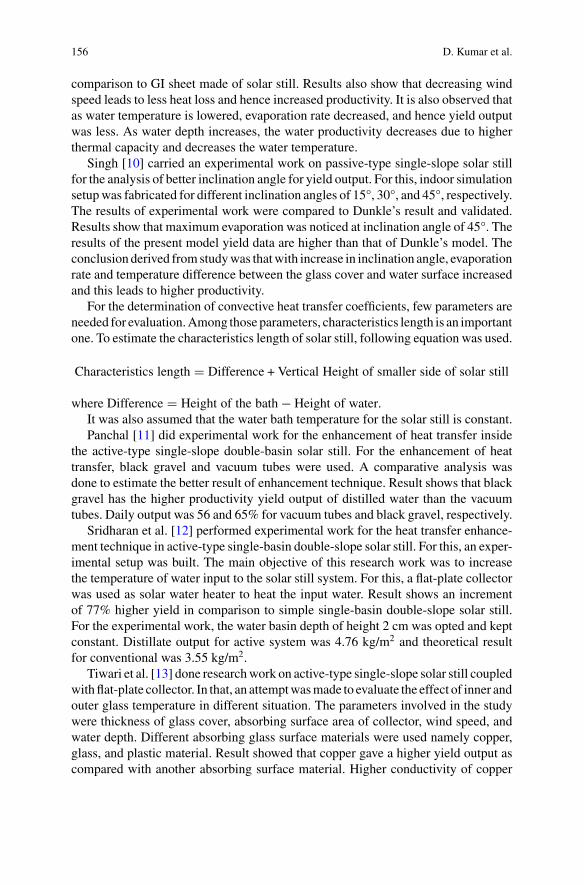
156 D. Kumar et al.
comparison to GI sheet made of solar still. Results also show that decreasing windspeed leads to less heat loss and hence increased productivity. It is also observed thatas water temperature is lowered, evaporation rate decreased, and hence yield outputwas less. As water depth increases, the water productivity decreases due to higherthermal capacity and decreases the water temperature.
Singh [10] carried an experimental work on passive-type single-slope solar stillfor the analysis of better inclination angle for yield output. For this, indoor simulationsetupwas fabricated for different inclination angles of 15°, 30°, and 45°, respectively.The results of experimental work were compared to Dunkle’s result and validated.Results show that maximum evaporation was noticed at inclination angle of 45°. Theresults of the present model yield data are higher than that of Dunkle’s model. Theconclusion derived from studywas thatwith increase in inclination angle, evaporationrate and temperature difference between the glass cover and water surface increasedand this leads to higher productivity.
For the determination of convective heat transfer coefficients, few parameters areneeded for evaluation.Among those parameters, characteristics length is an importantone. To estimate the characteristics length of solar still, following equation was used.
Characteristics length � Difference + Vertical Height of smaller side of solar still
where Difference � Height of the bath − Height of water.It was also assumed that the water bath temperature for the solar still is constant.Panchal [11] did experimental work for the enhancement of heat transfer inside
the active-type single-slope double-basin solar still. For the enhancement of heattransfer, black gravel and vacuum tubes were used. A comparative analysis wasdone to estimate the better result of enhancement technique. Result shows that blackgravel has the higher productivity yield output of distilled water than the vacuumtubes. Daily output was 56 and 65% for vacuum tubes and black gravel, respectively.
Sridharan et al. [12] performed experimental work for the heat transfer enhance-ment technique in active-type single-basin double-slope solar still. For this, an exper-imental setup was built. The main objective of this research work was to increasethe temperature of water input to the solar still system. For this, a flat-plate collectorwas used as solar water heater to heat the input water. Result shows an incrementof 77% higher yield in comparison to simple single-basin double-slope solar still.For the experimental work, the water basin depth of height 2 cm was opted and keptconstant. Distillate output for active system was 4.76 kg/m2 and theoretical resultfor conventional was 3.55 kg/m2.
Tiwari et al. [13] done researchwork on active-type single-slope solar still coupledwithflat-plate collector. In that, an attemptwasmade to evaluate the effect of inner andouter glass temperature in different situation. The parameters involved in the studywere thickness of glass cover, absorbing surface area of collector, wind speed, andwater depth. Different absorbing glass surface materials were used namely copper,glass, and plastic material. Result showed that copper gave a higher yield output ascompared with another absorbing surface material. Higher conductivity of copper
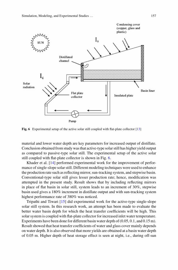
Simulation, Modeling, and Experimental Studies … 157
Fig. 6 Experimental setup of the active solar still coupled with flat-plate collector [13]
material and lower water depth are key parameters for increased output of distillate.Conclusion obtained from studywas that active-type solar still has higher yield outputas compared to passive-type solar still. The experimental setup of the active solarstill coupled with flat-plate collector is shown in Fig. 6.
Khader et al. [14] performed experimental work for the improvement of perfor-mance of single-slope solar still. Differentmodeling techniqueswere used to enhancethe production rate such as reflectingmirror, sun-tracking system, and stepwise basin.Conventional-type solar still gives lesser production rate; hence, modification wasattempted in the present study. Result shows that by including reflecting mirrorsin place of flat basin in solar still, system leads to an increment of 30%, stepwisebasin used gives a 180% increment in distillate output and with sun-tracking systemhighest performance rate of 380% was noticed.
Tripathi and Tiwari [15] did experimental work for the active-type single-slopesolar still system. In this research work, an attempt has been made to evaluate thebetter water basin depth for which the heat transfer coefficients will be high. Thissolar system is coupled with flat-plate collector for increased inlet water temperature.Experiments have been done for different basinwater depth of (0.05, 0.1, and 0.15m).Result showed that heat transfer coefficients of water and glass cover mainly dependsonwater depth. It is also observed that more yields are obtained at a basin water depthof 0.05 m. Higher depth of heat storage effect is seen at night, i.e., during off-sun
158 D. Kumar et al.
shine hours, because of same basin water depth, it showed a higher productivity atnights as compared to day time.
3 Simulation Modeling of Solar Stills
Setoodeh et al. [16] used CFD simulation tool for a three-dimensional two-phasemodels to show the evaporation and condensation process in single-slope solar still.This model was developed in the volume of liquid (VOF) framework for fluid water,a mixture of air and water vapors in quasi-static state condition. Model geometryand its meshing were done using ANSYS Workbench 11. The tetrahedral meshingtype was used. Simulations were carried out with 47,179 nodes. The energy balanceequations considered for the numerical modeling was heat transfer, mass transfer,and continuity equations. The results obtained from CFD are clearly evident withthe fact that it is efficient and sharp modeling software for design.
Singh and Mittal [17] have done simulation work for passive-type single-slopesolar still to find out the suitable inclination angle for the better productivity result.Simulation work is done with the help of ANSYS CFX 13. Geometric model wascreated in ANSYS CAD module and imported to ANSYS meshing module for thegeneration of mesh. Boundary condition was applied to solve the momentum andcontinuity equation. For the simulation process of solar still, two condensing glasscovers having slopes equal to 15° and 30°were chosen. Simulation is carried out in thetemperature difference between 40 and 60 °C at an interval of 2 °C for each reading.The simulation result is shown in Fig. 7. For droplet formation on condensing cover,adhesive forces are taken into consideration and it is observed that condensing coverat inclination of 30° obtains the highest convective and evaporative heat transfercoefficient. The condensing cover at 30° slope gives higher production efficiencyrate of 29.4% than 15° slope.
During the simulation processes, following assumption were made:
i. Bottom temperature is equal to the water temperature inside the solar still.ii. Temperature of the distillate collector is assumed to be equal of glass tempera-
ture.iii. Only adhesive forces are considered for the droplet formation.iv. All the side wall of solar still assumed to be adiabatic since there is no heat loss
to the surrounding.v. No slip boundary is being specified for the liquid phase, and it is specified for
the vapor phase.
Following boundary conditions were applied during simulation process and itsvarious conditions are being presented in Table 1.
Panchal et al. [18] worked in ANSYS CFX tool for modeling and simulationtechnique to represent a model of passive single-slope solar still. To study the simu-lation process of evaporation as well as condensation phenomenon in solar still, thetwo-phase, three-dimensional model was created. The model geometry and meshing
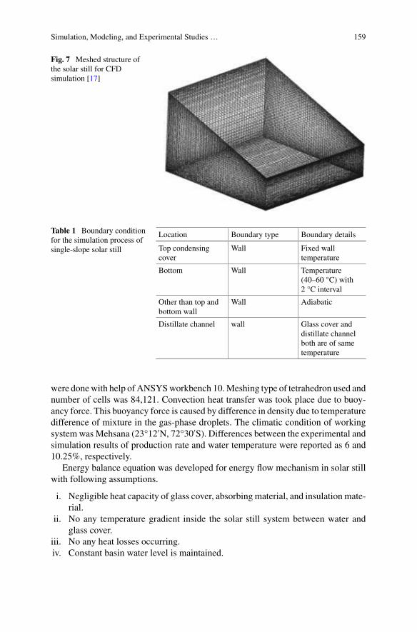
Simulation, Modeling, and Experimental Studies … 159
Fig. 7 Meshed structure ofthe solar still for CFDsimulation [17]
Table 1 Boundary conditionfor the simulation process ofsingle-slope solar still
Location Boundary type Boundary details
Top condensingcover
Wall Fixed walltemperature
Bottom Wall Temperature(40–60 °C) with2 °C interval
Other than top andbottom wall
Wall Adiabatic
Distillate channel wall Glass cover anddistillate channelboth are of sametemperature
were donewith help of ANSYSworkbench 10.Meshing type of tetrahedron used andnumber of cells was 84,121. Convection heat transfer was took place due to buoy-ancy force. This buoyancy force is caused by difference in density due to temperaturedifference of mixture in the gas-phase droplets. The climatic condition of workingsystem wasMehsana (23°12′N, 72°30′S). Differences between the experimental andsimulation results of production rate and water temperature were reported as 6 and10.25%, respectively.
Energy balance equation was developed for energy flow mechanism in solar stillwith following assumptions.
i. Negligible heat capacity of glass cover, absorbing material, and insulation mate-rial.
ii. No any temperature gradient inside the solar still system between water andglass cover.
iii. No any heat losses occurring.iv. Constant basin water level is maintained.
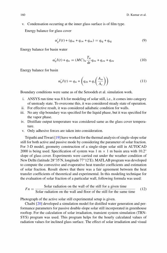
160 D. Kumar et al.
v. Condensation occurring at the inner glass surface is of film type.
Energy balance for glass cover
α′g I (t) + (qrw + qcw + qew) � qrg + qeg (9)
Energy balance for basin water
α′b I (t) + qw � (MC)w
Twdt
qrw + qcw + qew (10)
Energy balance for basin
α′b I (t) � qw +
(qcb + qs
(Ass
As
))(11)
Boundary conditions were same as of the Setoodeh et al. simulation work.
i. ANSYS run time was 8 h for modeling of solar still, i.e., it comes into categoryof unsteady state. To overcome this, it was considered steady state of operation.
ii. For effective result, it was considered adiabatic condition for walls.iii. No any slip boundary was specified for the liquid phase, but it was specified for
the vapor phase.iv. Distillate output temperature was considered same as the glass cover tempera-
ture.v. Only adhesive forces are taken into consideration.
Tripathi and Tiwari [19] haveworked for the thermal analysis of single-slope solarstill for both active and passive mode by considering the parameter of solar fraction.For 3-D model, geometry construction of a single-slope solar still in AUTOCAD2000 is being used. Specification of system was 1 m × 1 m basin area with 10.2°slope of glass cover. Experiments were carried out under the weather condition ofNewDelhi (latitude 28°35′N, longitude 77°12′E).MATLABprogramwas developedto compute the convective and evaporative heat transfer coefficients and estimationof solar fraction. Result shows that there was a fair agreement between the heattransfer coefficients of theoretical and experimental. In this modeling technique forthe evaluation of solar fraction of a particular wall, following formula was used:
Fn � Solar radiation on the wall of the still for a given time
Solar radiation on the wall and floor of the still for the same time(12)
Photograph of the active solar still experimental setup is given.Chaibi [20] developed a simulation model for distilled water generation and per-
formance parameters for passive double-slope solar still incorporated in greenhouserooftop. For the calculation of solar irradiation, transient system simulation (TRN-SYS) program was used. This program helps for the hourly calculated values ofradiation values for inclined glass surface. The effect of solar irradiation and visual
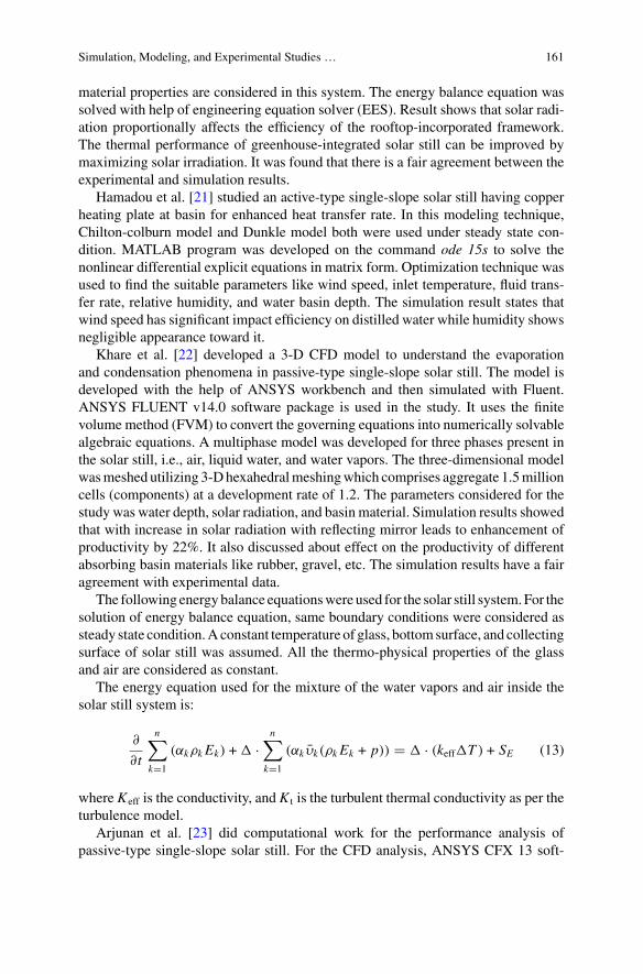
Simulation, Modeling, and Experimental Studies … 161
material properties are considered in this system. The energy balance equation wassolved with help of engineering equation solver (EES). Result shows that solar radi-ation proportionally affects the efficiency of the rooftop-incorporated framework.The thermal performance of greenhouse-integrated solar still can be improved bymaximizing solar irradiation. It was found that there is a fair agreement between theexperimental and simulation results.
Hamadou et al. [21] studied an active-type single-slope solar still having copperheating plate at basin for enhanced heat transfer rate. In this modeling technique,Chilton-colburn model and Dunkle model both were used under steady state con-dition. MATLAB program was developed on the command ode 15s to solve thenonlinear differential explicit equations in matrix form. Optimization technique wasused to find the suitable parameters like wind speed, inlet temperature, fluid trans-fer rate, relative humidity, and water basin depth. The simulation result states thatwind speed has significant impact efficiency on distilled water while humidity showsnegligible appearance toward it.
Khare et al. [22] developed a 3-D CFD model to understand the evaporationand condensation phenomena in passive-type single-slope solar still. The model isdeveloped with the help of ANSYS workbench and then simulated with Fluent.ANSYS FLUENT v14.0 software package is used in the study. It uses the finitevolume method (FVM) to convert the governing equations into numerically solvablealgebraic equations. A multiphase model was developed for three phases present inthe solar still, i.e., air, liquid water, and water vapors. The three-dimensional modelwasmeshed utilizing 3-Dhexahedralmeshingwhich comprises aggregate 1.5millioncells (components) at a development rate of 1.2. The parameters considered for thestudy was water depth, solar radiation, and basin material. Simulation results showedthat with increase in solar radiation with reflecting mirror leads to enhancement ofproductivity by 22%. It also discussed about effect on the productivity of differentabsorbing basin materials like rubber, gravel, etc. The simulation results have a fairagreement with experimental data.
The following energybalance equationswere used for the solar still system.For thesolution of energy balance equation, same boundary conditions were considered assteady state condition.Aconstant temperature of glass, bottomsurface, and collectingsurface of solar still was assumed. All the thermo-physical properties of the glassand air are considered as constant.
The energy equation used for the mixture of the water vapors and air inside thesolar still system is:
∂
∂t
n∑
k�1
(αkρk Ek) + � ·n∑
k�1
(αk υk(ρk Ek + p)) � � · (keff�T ) + SE (13)
where Keff is the conductivity, and K t is the turbulent thermal conductivity as per theturbulence model.
Arjunan et al. [23] did computational work for the performance analysis ofpassive-type single-slope solar still. For the CFD analysis, ANSYS CFX 13 soft-
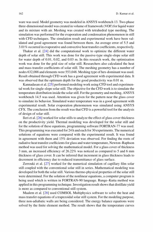
162 D. Kumar et al.
ware was used. Model geometry was modeled in ANSYS workbench 13. Two-phasethree-dimensionalmodel was created in volume of framework (VOF) for liquidwaterand its mixture with air. Meshing was created with tetrahedral type meshing. Thesimulation was performed for the evaporation and condensation phenomenon in stillwith CFD techniques. The simulation result and experimental work have been val-idated and good agreement was found between them. An average error of 5.5 and3.01% occurred in evaporative and convective heat transfer coefficients, respectively.
Thakur et al. [24] did the computational work to optimize the different waterdepth of solar still. This work was done for the passive-type single-slope solar stillfor water depth of 0.01, 0.02, and 0.03 m. In this research work, the optimizationwork was done for the grid size of solar still. Researchers also calculated the heatand mass transfer coefficients of solar still. The meshing geometry has a number ofnodes 632,088 and elements were 553,048.Meshing type of hex-dominant was used.Result obtained through CFD work has a good agreement with experimental data. Itwas observed that the optimum depth for the good productivity was 0.01 m.
Kannadasan et al. [25] performed modeling work using CFD tool and experimen-tal work for single-slope solar still. The objective for the CFDwork is to simulate thetemperature distribution inside the solar still. For the geometry andmeshing, ANSYSworkbench 14.5 was used. Attention was given for the pattern near the glass coverto simulate its behavior. Simulated water temperature was in a good agreement withexperimental result. Solar evaporation phenomenon was simulated using ANSYSCFX. The conclusion from the result was that CFD is a powerful tool for the analysisof design of solar still.
Ileri et al. [26] worked for solar stills to analyze the effect of glass cover thicknesson the productivity yield. Thermal modeling was developed for the solar still andfor the solution of these equations, programming software FORTRAN-77 was used.This programmingwas executed for 24 h and each for 30 experiments. The numericalsolutions of equations were compared with the experimental result. It was foundin agreement with them and 15% deviation was observed. For finding the roots ofradiative heat transfer coefficients for glass andwater temperature, Newton–Raphsonmethod was used for solving the mathematical model. For a glass cover of thickness3 mm, an increased efficiency of 26.22% was noticed as compared to 5 and 6 mmthickness of glass cover. It can be inferred that increment in glass thickness leads todecrement in efficiency due to reduced transmittance of glass surface.
Zerrouki et al. [27] worked for the numerical simulation of capillary film solarstill coupled with the conventional solar still in series. Mathematical modeling wasdeveloped for both the solar still. Various thermo-physical properties of the solar stillwere determined. For the solution of the nonlinear equations, a computer program isbeing used which is written in FORTRAN-90 language. Runge–Kutta method wasapplied in this programming technique. Investigation result shows that distillate yieldis more as compared to conventional still system.
Maalem et al. [28] used COMSOL Multiphysics software to solve the heat andmass transfer equations of a trapezoidal solar still system. For the modeling purpose,three non-adiabatic walls are being considered. The energy balance equations weresolved by the finite element method. The result shows that the temperature curves
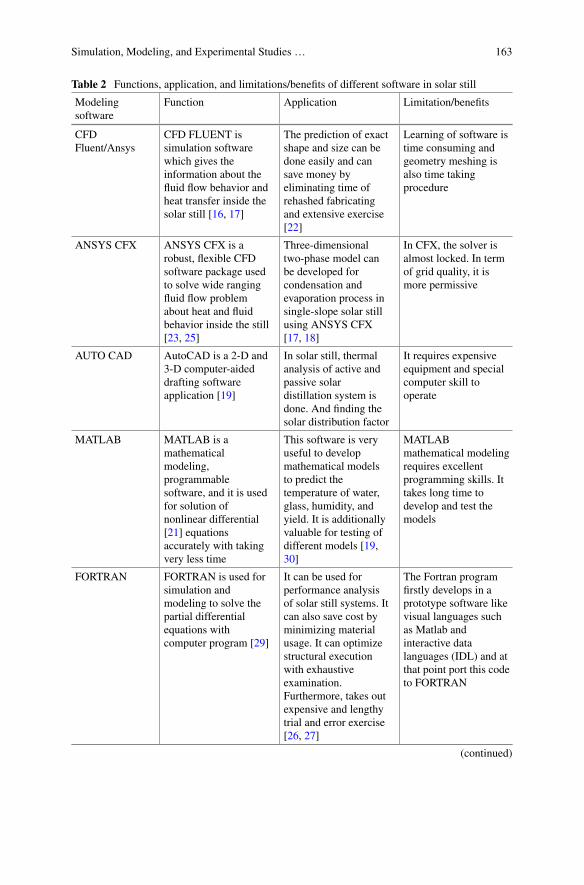
Simulation, Modeling, and Experimental Studies … 163
Table 2 Functions, application, and limitations/benefits of different software in solar still
Modelingsoftware
Function Application Limitation/benefits
CFDFluent/Ansys
CFD FLUENT issimulation softwarewhich gives theinformation about thefluid flow behavior andheat transfer inside thesolar still [16, 17]
The prediction of exactshape and size can bedone easily and cansave money byeliminating time ofrehashed fabricatingand extensive exercise[22]
Learning of software istime consuming andgeometry meshing isalso time takingprocedure
ANSYS CFX ANSYS CFX is arobust, flexible CFDsoftware package usedto solve wide rangingfluid flow problemabout heat and fluidbehavior inside the still[23, 25]
Three-dimensionaltwo-phase model canbe developed forcondensation andevaporation process insingle-slope solar stillusing ANSYS CFX[17, 18]
In CFX, the solver isalmost locked. In termof grid quality, it ismore permissive
AUTO CAD AutoCAD is a 2-D and3-D computer-aideddrafting softwareapplication [19]
In solar still, thermalanalysis of active andpassive solardistillation system isdone. And finding thesolar distribution factor
It requires expensiveequipment and specialcomputer skill tooperate
MATLAB MATLAB is amathematicalmodeling,programmablesoftware, and it is usedfor solution ofnonlinear differential[21] equationsaccurately with takingvery less time
This software is veryuseful to developmathematical modelsto predict thetemperature of water,glass, humidity, andyield. It is additionallyvaluable for testing ofdifferent models [19,30]
MATLABmathematical modelingrequires excellentprogramming skills. Ittakes long time todevelop and test themodels
FORTRAN FORTRAN is used forsimulation andmodeling to solve thepartial differentialequations withcomputer program [29]
It can be used forperformance analysisof solar still systems. Itcan also save cost byminimizing materialusage. It can optimizestructural executionwith exhaustiveexamination.Furthermore, takes outexpensive and lengthytrial and error exercise[26, 27]
The Fortran programfirstly develops in aprototype software likevisual languages suchas Matlab andinteractive datalanguages (IDL) and atthat point port this codeto FORTRAN
(continued)
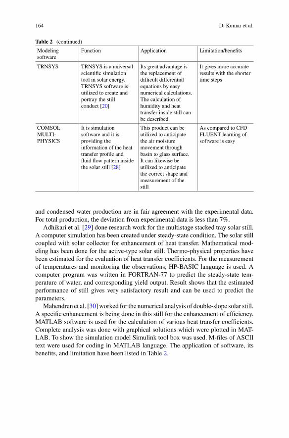
164 D. Kumar et al.
Table 2 (continued)
Modelingsoftware
Function Application Limitation/benefits
TRNSYS TRNSYS is a universalscientific simulationtool in solar energy.TRNSYS software isutilized to create andportray the stillconduct [20]
Its great advantage isthe replacement ofdifficult differentialequations by easynumerical calculations.The calculation ofhumidity and heattransfer inside still canbe described
It gives more accurateresults with the shortertime steps
COMSOLMULTI-PHYSICS
It is simulationsoftware and it isproviding theinformation of the heattransfer profile andfluid flow pattern insidethe solar still [28]
This product can beutilized to anticipatethe air moisturemovement throughbasin to glass surface.It can likewise beutilized to anticipatethe correct shape andmeasurement of thestill
As compared to CFDFLUENT learning ofsoftware is easy
and condensed water production are in fair agreement with the experimental data.For total production, the deviation from experimental data is less than 7%.
Adhikari et al. [29] done research work for the multistage stacked tray solar still.A computer simulation has been created under steady-state condition. The solar stillcoupled with solar collector for enhancement of heat transfer. Mathematical mod-eling has been done for the active-type solar still. Thermo-physical properties havebeen estimated for the evaluation of heat transfer coefficients. For the measurementof temperatures and monitoring the observations, HP-BASIC language is used. Acomputer program was written in FORTRAN-77 to predict the steady-state tem-perature of water, and corresponding yield output. Result shows that the estimatedperformance of still gives very satisfactory result and can be used to predict theparameters.
Mahendren et al. [30]worked for the numerical analysis of double-slope solar still.A specific enhancement is being done in this still for the enhancement of efficiency.MATLAB software is used for the calculation of various heat transfer coefficients.Complete analysis was done with graphical solutions which were plotted in MAT-LAB. To show the simulation model Simulink tool box was used. M-files of ASCIItext were used for coding in MATLAB language. The application of software, itsbenefits, and limitation have been listed in Table 2.
Simulation, Modeling, and Experimental Studies … 165
4 Conclusion
Based rigorous literature review, it is being observed that solar still is one of themost prominent solar thermal applications. Solar still works on the principle of solardistillation and provides potable water for direct human consumption. It fulfills theneeds of the potable water with least expenditure. In this system, raw water getsdistilled without any use of the fossil fuel. In this study, a comprehensive review ofthe various types of the solar still is being presented. In this work, a state-of-the-artreview on both experimental work as well as computational work on the solar still isbeing presented. By properly utilizing the computation study, one can save time of thetedious experimental work. This work will be useful for the scientists, industrialists,and researchers who are working in this field.
References
1. Sampathkumar K, Senthilkumar P (2012) Utilization of solar water heater in a single basinsolar still-an experimental study. Desalination 297:8–19
2. Panchal HN, Patel N (2017) ANSYS CFD and experimental comparison of various parametersof a solar still. Int J Ambient Energy:1–7
3. Fathy M, Hassan H, AhmedMS (2018) Experimental study on the effect of coupling parabolictrough collector with double slope solar still on its performance. Sol Energy 163:54–61
4. Hind, Banaras (2015) Theoretical investigation of solar still coupledwith solar air heater. SSRGInt J Mech Eng (SSRG-IJME) 2(9):0–5
5. Kumar S (2013) Thermal-economic analysis of a hybrid photovoltaic thermal (PVT) activesolar distillation system: role of carbon credit. Urban Clim 5:112–124
6. Sahota L, Shyam, Tiwari GN (2017) Energy matrices, enviroeconomic and exergoeconomicanalysis of passive double slope solar still with water based nanofluids. Desalination 409:66–79
7. Madhlopa A, Johnstone CM (2011) Computation of solar radiation distribution in a solar stillwith internal and external reflectors. Sol Energy 85(2):217–233
8. Badran OO (2007) Experimental study of the enhancement parameters on a single slope solarstill productivity. Desalination 209(1–3 SPEC. ISS.):136–143
9. Gnanadason MK, Kumar SP, Wilson VH, Kumaravel A, Jebadason B (2013) Comparison ofperformance analysis between single basin solar still made up of copper and GI. Int J InnovRes Sci Eng Technol (IJIREST) 2(7):3175–3183
10. Singh N (2013) Performance analysis of single slope solar stills at different inclination angles:an indoor simulation. Int J Curr Eng Technol 3(2):677–684
11. Panchal HN (2015) Enhancement of distillate output of double basin solar still with vacuumtubes. J King Saud Univ Eng Sci 27(2):170–175
12. Chinnathambi S, Sridharan M (2014) Performance enhancement study on single basin doubleslope solar still using flat plate collector. Int J Innov Res Sci Eng Technol 3(3):1303–1308
13. Dimri V, Sarkar B, Singh U, Tiwari GN (2008) Effect of condensing cover material on yieldof an active solar still: an experimental validation. Desalination 227(1–3):178–189
14. Abdallah S, Badran O, Abu-Khader MM (2008) Performance evaluation of a modified designof a single slope solar still. Desalination 219(1–3):222–230
15. Tripathi R, Tiwari GN (2005) Effect of water depth on internal heat and mass transfer for activesolar distillation. Desalination 173(2):187–200
16. SetoodehN, Rahimi R,Ameri A (2011)Modeling and determination of heat transfer coefficientin a basin solar still using CFD. Desalination 268(1–3):103–110

166 D. Kumar et al.
17. Singh A, Mittal MK (2014) Simulation of single slope solar still at different inclinations usingCFD. Int Conf Adv Res Innov:512–519
18. Panchal HN, Shah PK (2011) Modelling and verification of single slope solar still usingANSYS-CFX. Int J Energy Environ 2(6):985–998
19. Tripathi R, Tiwari GN (2006) Thermal modeling of passive and active solar stills for differentdepths of water by using the concept of solar fraction. Sol Energy 80(8):956–967
20. Chaibi MT (2000) Analysis by simulation of a solar still integrated in a greenhouse roof.Desalination 128(2):123–138
21. Hamadou OA, Abdellatif K (2014) Modeling an active solar still for sea water desalinationprocess optimization. Desalination 354:1–8
22. Khare VR, Singh AP, Kumar H, Khatri R (2017) Modelling and performance enhancement ofsingle slope solar still using CFD. Energy Procedia 109:447–455
23. Kumar D, Himanshu P, Ahmad Z (2013) Performance analysis of single slope solar still. Int JMech Robot Res 3(3):66–72
24. Thakur AK, Pathak SK (2017) Single basin solar still with varying depth of water: optimizationby computational method. Iran J Energy Environ 8:216–223
25. Gokilavani NS, PrabhakaranD, Kannadasan T (2014) Experimental studies and CFDmodelingon solar distillation system. Int J Innov Res Sci Eng Technol 3(9):15818–15822
26. Ghoneyem A, Ileri A (1997) Software to analyze solar stills and an experimental study on theeffects of the cover. Desalination 114(1):37–44
27. Zerrouki M, Settou N, Marif Y, Belhadj MM (2014) Simulation study of a capillary filmsolar still coupled with a conventional solar still in South Algeria. Energy Convers Manag85:112–119
28. MaalemMS, Benzaoui A, Bouhenna A (2014) Modeling of simultaneous transfers of heat andmass in a trapezoidal solar distiller. Desalination 344:371–382
29. Adhikari RS, Kumar A, Sootha GD (1995) Simulation studies on a multi-stage stacked traysolar still. Sol Energy 54:317–325
30. Ali I, Senthilkumar R, Mahendren R (2011) Modelling of solar still using granular activatedcarbon in matlab. Bonfring Int J Power Syst Integr Circ 1:5–10
Progress in Passive Solar Stillfor Enhancement in Distillate Output
Hitesh Panchal
Abstract There is a scarcity of consumable water on the planet today, and on theopposite side, plentiful water is accessible in the ocean which is not consumable.Sun-oriented vitality is likewise accessible in bottomless quantity; henceforth, ifsun-oriented vitality is used to change the saline or ocean water into consumablewater, then the issue of consumable water can be reduced. Introduce survey paperdemonstrates the advance in uninvolved sun oriented still to enhance the distillateyield. It indicates the exhaustive work done by specialists from all around the globeto upgrade the distillate yield.
Keywords Passive solar still · Distillate output · Efficiency
1 Introduction
Under 1% water is accessible in the earth and accessible in lake, ocean, well andso on, and remaining water is not potable or drinkable water. Additionally, becauseof augmentation in universe populace, the measure of drinkable water is increasingstep by step. Likewise the wellsprings of consumable water are constrained; conse-quently, the researchers are doing research on customary and additionally nonregularvitality sources. Utilization of customary sources makes contamination in the earth;subsequently, the nonordinary sources are just arrangement on the planet today. Pan-chal [1–4], Panchal et al. [5–7], Panchal and Shah [8–19], Panchal and Patel [3],Panchal and Mohan [20] and Panchal and Sanjay [21].
H. Panchal (B)Department of Mechanical Engineering, Government EngineeringCollege Patan, Katpur, Indiae-mail: [email protected]
© Springer Nature Singapore Pte Ltd. 2019A. Kumar and O. Prakash (eds.), Solar Desalination Technology,Green Energy and Technology, https://doi.org/10.1007/978-981-13-6887-5_7
167
168 H. Panchal
2 Research Work on Passive Solar Still
Dynamic and in addition Passive sun-based still are two fundamental kinds of sun-oriented still on which investigation works have done by researchers. In uninvolvedsun-based still, just sun-oriented vitality is in charge of distillate yield. In Activesun-oriented still, sun powered vitality and additionally incorporation of gatherer isin charge of augmentation in distillate yield. The exploration takes a shot at aloofsun-oriented still and is exhibited underneath:
Moustafa and Brusewitz [22] had outlined and manufactured wick compose sun-oriented still with water streaming framework controlled by stream controller andstop valve for the assessment of augmentation in distillate yield. They found that,stream framework is more beneficial for increase in distillate yield. Prakash andKavanthekar [23] presented regenerative inactive sun powered still and contrastedand same zone and atmosphere conditions. They additionally made warm exami-nation of regenerative sun powered still to foresee its execution and got a decentconcurrence with warm investigation and test examination. Tiwari and Thakur [24]had completed the explanatory articulation for count of effectiveness of detachedsunlight-based still. They took diverse factors like the mass of water in the bowl,sunlight-based insolation, wind speed, and so on. They discovered 2.4 kg normaldistillate yield of inactive sun-oriented still. They reasoned that the lower mass,higher insolation, and lower wind speed expanded productivity of a sun-orientedstill. Yadav and Kumar (1991) had composed and tried single bowl detached sun-oriented still and tried in atmosphere states of Delhi to decide the impacts of saltwater profundity on glass cover temperature, distillate yield, and productivity. Theyinferred that, distillate yield and proficiency of inactive sun powered still expandedby bringing downmass of salt water inside sunlight-based still and furthermore glasscover temperature diminished by bringing down mass of saline solution. Yeh [25]had dissected the execution of upward twofold impact sun-oriented distiller. The stillwas put at 10° tendencies to a flat surface. He found that, utilization of upward-typetwofold—impact sun-oriented still gave more proficient than descending sort unitdue to the higher temperature ascent of water in upward-type latent sun based still.Mowla and Karimi [26] had built up a scientific model for single slant, single bowldetached sun powered as yet having zone of 1 m2 with reversed V write glass coverand contrasted with the model. They discovered great concurrence with the results.Adhikari et al. [27] had built up another idea of sun-based still, a multi-organizestacked sun powered still. The major point of the exploration work was to contrastexploratory outcomes and hypothetical outcomes and discovered great assentation ofhypothetical model and trial comes about. Aboul-Enein et al. [28] arranged a numer-ical model of uninvolved sunlight-based still in light of observational formulae ofvitality adjust conditions of different basic parts like glass cover, safeguard plate, andwater mass. They additionally dissected numerical reenactment which comes withtrial results and discovered great understanding.
Progress in Passive Solar Still for Enhancement in Distillate … 169
Bilal et al. [29] had assessed the impact of utilizing different sun-oriented vitalityretaining materials like dark elastic mate, dark color, and dark ink to assess executionexamination of inactive sun-based still.
Khalifa et al. [30] had indicated change of sunlight-based still for increase inthe distillate yield by preheating of the saline water and using outside and interiorcondensers. Theyfinished up impressive increment in distillate yield of a sun poweredstill by preheating the water and inner and outside condensers. El-Bahi and Inan(1999) had manufactured enhanced outline of an uninvolved sunlight-based stillincorporated with an evaporator territory of 1 m2 secured with 6 mm thickness ofglass cover with a condenser through flat opening. They led a few analyses in Iranand contrasted and a similar zone of detached sunlight-based still and found thatenhanced outline of sun powered still builds distillate yield fundamentally. El-Sebaiiet al. [31] had examinedmica as suspended safeguardmaterial on the investigation ofa traditional detached sun powered still. To lessen the side and base misfortunes wasthe prime point of their exploration work. They found 11% expansion in distillateyield.
Abou-Rayan and Djebdedjian [32] had analyzed the execution of a latent sun-based still by Navier–strokes condition. They arranged a scientific model by think-ing about a blend of air and water vapor blend and got a decent concurrence withexploratory outcomes. Al-Hinani et al. [33] had considered hypothetical examinationof shallow bowl latent sun-oriented still to get comes about on glass cover, tilt, pro-tection impact, and black-top covering on the safeguard plate in atmosphere states ofOman. They found that the shallow water bowl with edge of tilt is equivalent to thescope of Oman with higher protection thickness and an addition of distillate yieldby the black-top bowl absorber. Voropoulos et al. [34] had tentatively and hypothet-ically assessed the conduct of aloof sun-oriented still in light of atmosphere infor-mation and working conditions in Jeddah. They found that, the principle atmosphereinformation and working conditions significantly affect uninvolved sun-oriented stilldistillate yield. They likewise got great straight relationship. Fath Hassan and Hosny[35] had recommended the utilization of balance on one of the consolidating coversfor improvement of the warmth exchange from outside gathering spread to the sur-rounding for higher vanishing. They discovered 55% augmentation in distillate yieldby utilization of balance on the gathering front of inactive sun-oriented still. Valsaraj[36] had led an examinations on the single slant, single bowl aloof sunlight-basedstill with a coasting punctured aluminum sheet on the surface of saline solution forsignificant concentrating sun beams. This game plan keeps the entire water mass get-ting warmed and henceforth increase in distillate yield significantly when the waterprofundity is high.
Ward [37] designed and fabricated anewmodular plastic solar still.He took severallaboratory experiments with the help of solar simulator and received considerabledistillate output of passive solar still in laboratory conditions due to neglecting losses.Bassam et al. [38, 39] had spreader sponge cubes inside the passive solar still forincreasing surface area of brine. They took several experiments with different depthswith same size sponge cubes and received a 20% increase in distillate output dueto capillary action of water inside the sponge cubes. Abdallah and Badran [40] had
170 H. Panchal
proposed a new concept of increasing the distillate output of passive solar still bysolar tracking mechanism. To track the sun and increase distillate output were theobjectives of their research work and they found a remarkable increase in potablewater production in still.
Naim and Mervat [41] had examined the impact of utilizing charcoal as warmthstockpiling material in atmosphere states of Jordan. They found that, charcoal is asuccessful warmth stockpiling material for expanding 20% distillate yield of aloofsunlight based still. Tiwari et al. (2003) proposed a PC demonstrate for differentwarmth exchange coefficients for assessing the numerical reproduction aftereffectsof internal glass cover temperature, external glass cover temperatures, and distillateyield. They inferred that, PC show is a best strategy to assess hypothetical investiga-tion of above parameters. Ben Bacha et al. [42] performed hypothetical investigationand model of the inventive refining module in light of sun-based numerous buildup,vanishing cycle, and tried in atmosphere states of Egypt. They found a decent assen-tation among hypothetical and exploratory results. Shukla [43] prepared a PC modelof the customary uninvolved sun-oriented still to assess the hypothetical distillateyield in view of the vitality adjust condition. They contrasted hypothetical distillateyield and trial distillate yield and discovered great understanding.
Al-Karaghouli and Alnaser [44] had performed examinations to investigateimprovements in distillate yield from twofold bowl and single bowl latent still inatmosphere states of Jeddah. From a half year of nonstop work, they presumed that,twofold bowl sunlight-based still expanded distillate yield of 40% more contrastedand single bowl still.
Hansonet al. [45] had done in-house and field preliminaries on the execution ofsingle bowl latent sun-oriented still for evacuation of a chose gathering of inorganicand bacteriological and natural defiles. They found that, capacity of evacuating sul-lies did not change altogether between the units and the capacity to expel the naturalmixes relies upon Constant of Total disintegrated strong. Shukla and Sorayan [46]had built up another method for upgrade in the distillate yield of uninvolved sunpowered still by utilization of Jute material. They found that, jute fabric has a prop-erty to build dissipation because of decrease in saline water inside the bowl. Theyadditionally thought about hypothetical and test results and discovered great under-standing between them. Zeinab and Ashraf [47] had directed a few examinationson a solitary incline detached sun-oriented still with different sun-oriented vitalityengrossing materials like glass, elastic, dark rock for increase in distillate yield. Fol-lowing a multimonth of research on above materials, they found that, dark rock wasmore viable for expanding the distillate yield of inactive sun-based still took afterby elastic and glass. Sow et al. [48] had examined single, twofold, and triple impactdetached sunlight-based still in atmosphere states of Egypt by thought of variousmisfortunes. They found that, misfortunes of triple impact sun-based still were morecontrasted and single impact and twofold impact. Nijmeh et al. [49] had inspectedthe impacts of different sunlight-based vitality stockpiling materials on the distil-late yield of a detached sun-based still in atmosphere states of Spain. They utilizedbroke up salts, violet color, and charcoal and got 26% addition in distillate yield by
Progress in Passive Solar Still for Enhancement in Distillate … 171
utilization of potassium permanganate contrasted and regular aloof sunlight-basedstill.
Omri et al. [50] had prepared natural convection numerical modeling in triangularcavity with uniform solar insolation by control volume finite element method. Theirstudy proved that, the flow regime and the heat transfer were most critical parametersfor cavity and Rayleigh Number.
KauzoMurase et al. [51] proposed another idea of uninvolved sunlight-based stillcoordinated with water dispersion organize in atmosphere states of Algeria. Theytried tube compose sun-oriented still numerically and tentatively and got great agree-ment. Ayber [52] had contemplated slanted wick compose detached sun-based stilland reasoned that the day by day yield of such sun-oriented still is 2.5–3.5 kg/m2/dayfor summer states of Turkey. The normal water temperature accessible from suchdetached sunlight-based still is around 40 °C, which can be utilized for the house-hold application notwithstanding refined water.
Tanaka and Nakatake [53] had proposed another model of latent sunlight-basedstill by joining inner and outside reflectors for reflecting sun-oriented beams towardthe bowl. They completed a few trials in atmosphere states of China and inferred that,inner and outer reflectors expanded distillate yield of 48%. Tiwari and Tiwari [54]had assessed the execution of aloof sunlight-based still with changing the thicknessof brackish water in summer atmosphere states of New Delhi, India. They took fiveprofundities of water from 0.04 to 0.18 m amid 24 long stretches of time interimon various five days in seven days. They reasoned that bring down profundity ofbrackish water expanded distillate yield because of decline of volumetric warmthlimit. Omar Badran [55] had demonstrated an execution of aloof sunlight-based stillby fluctuating parameters on distillate yield. He led a few trials in atmosphere statesof Jordan and presumed that still expands distillate yield of 51%when it is joinedwitha black-top bowl liner and sprinkler and furthermore builds the nighttime generationof 16% by including above parameters.
Kumar and Bai [56] had performed research on passive solar still with newimproved condensation technique to provide better condensation of inner glass coverfor different brine samples. They concluded that higher distillate output from tapwater is available for comparison with seawater and dairy industry effluent.
Torchia-Nunez et al. [57] had performed enduring state transient hypotheticalenergy investigation of an inactive sun powered still to discover the variables con-centrated on the energy demolition. They inferred that, surrounding temperature wasnot a compelling parameter for energy effectiveness and protection thickness ought tobe higher than 0.02 m to get higher energy productivity. They likewise reasoned that,the better thermodynamic execution acquired when temperature holes were dimin-ished. Velamurugan et al. [58] had done a few investigations of the incorporationof wipe 3D shapes and balances with ventured sun-oriented still for better distil-late yield in atmosphere states of Tamil Nadu, India. Expanding the surface zone ofsalt water was the prime point of their present research. They got 30% addition indistillate yield by combined impacts of wipe solid shapes and balances. Shakthiveland Shanmugasudaram [59] had led an explore on different avenues regarding rockof various sizes as sun powered vitality retaining materials in uninvolved sunlight-
172 H. Panchal
based still. They took 2, 4, and 6 mm sizes of rock took for the present trial. Theylikewise directed warm examination of a sun-oriented still with different sizes ofrock and contrasted and trial results and discovered great ascension. After a basicreport, they found that, inactive sun powered still with 6-mm estimate rock was morebeneficial for expanding distillate yield. Sahoo et al. [60] had done work to expelthe fluoride content in drinking water utilizing sun-oriented still and furthermoreadjust the bowl liner and protection to build productivity and distillate yield. Theypresumed that, fluoride diminished by 92–96% and productivity expanded by 6%with reasonable darkened bowl liner and thermocol protection. Shanmugan et al.[61] had used sponsor reflect simply over the glass front of detached sun-orientedstill to reflect abundance sun beams for addition of sunlight-based still. They gotnoticeable 4.2 kg/m2 distillate yield by utilization of sponsor reflect.
Nafey et al. [62] had carried out an experiment of single-basin passive solarstill with use of concentration of surfactant on distillate output. They took differentconcentration of surfactant like 50, 100, 200, and 300 ppm added to solar still. Theyfound an increase in distillate output by 0.7, 2.5, 4.7. and 7% by use of 50, 100,200, and 300 ppm. They also conclude that, adding of more than 400 ppm decreasesdistillate output by 6%.
Jiang et al. [63] had fabricated desalination technique of passive solar still inte-grated with flash equipment. The aim of the work was to increase distillate yield byflashing of brine in solar still. They carried out theoretical analysis and comparedwith experiment analysis to see the agreement and found good agreement. Kabeel[64] had designed and tested concave-type passive solar still with the pyramid-shapeglass cover. They used Jute cloth as a wick material on the base of passive solarstill for better absorption of sun rays and increased distillate output by capillaryeffect. They found 30% increment in daily efficiency of a solar still compared withconventional still.
Kumar and Umanad [65] had proposed a bond chart procedure to assess thedistillate yield and proficiency of latent sun powered still numerically and contrastedand trial results and discovered great ascension. Ayber andAssefi (2009) had checkedon vital components influencing on the distillate yield of uninvolved sunlight-basedstill. In their investigation, they took different elements like glass cover edges, glasscover tendency edge, and salt water profundity on the distillate yield of uninvolvedsunlight-based still. After a thorough survey of a half year, they proposed themajorityof the above parameters for increase in distillate output. Abdullah et al. [66] hadconsidered different wick materials on the distillate yield of aloof sun-based still.Wick materials spread inside the still and expanded distillate yield. They directeddifferent examinations in atmosphere states of Jordan. They discovered volcanicshakes as best wick material, and it expanded distillate yield by 45%.
Feilizadeh et al. [67] proposed another idea of aloof sun-oriented still executioninvestigation called a radiation show. They took different impacts of the radiationshow on water surface, side dividers, and back dividers of an inactive sun-orientedstill. They inferred that, side dividers and back dividers critically affect sun-orientedstill distillate yield and effectiveness. Dwivedi and Tiwari [68] had assessed lifecycle cost investigation of twofold and single slant latent sunlight-based still in
Progress in Passive Solar Still for Enhancement in Distillate … 173
atmosphere states of New Delhi, India. The point of their examination work wasto look at single and twofold slant, sun powered still with same saline solutionprofundity in atmosphere states of New Delhi, India. They presumed that, solitaryslant latent sun powered is discovered more profitable contrasted and a twofold slantuninvolved sun-oriented still. Kalidasa Murugavelet al. [69] had utilized differentsensible warmth stockpiling materials like quartzite shake, red blocks pieces, bond,solid pieces, washed stones, and iron pieces on the distillate yield of inactive sun-oriented still. They found that, quartzite shake is a best sensible warmth stockpilingmaterial.
Khaled [70] had manufactured latent sunlight-based still with pressed media forincrease in distillate yield. They utilized helical copper spring as adaptable stuffedmedium to create symphonious swaying. They found that, copper spring producesgreat vibrating impact on expanding distillate yield 3.4 kg/m2/day and incrementof productivity 35% contrasted and customary sun-based still. Setoodeh et al. [71]had arranged a model in ANSYS CFD in light of dissipation and buildup processthat happens in the latent sun powered still. They contrasted reproduction resultsand 24-h time interim to acquire fitting outcomes and got great concurrence with theaftereffects of recreations and tests.
Khalifa and Ibrahim (2011) had explained performance analysis of a passivesolar still for evaluation of distillate output with internal and external reflector tiltedat 0°, 10°, 20°, 30°, and 40° angles. They compared experimental results with amathematical model results and received good similarity in results.
Dev et al. [72] proposed a characteristic equations and correlation analysis forpredicting performance of double slope passive solar still in climate conditions ofNew Delhi, India. They used quasi-static conditions for the analysis and obtainedgood agreement of regression analysis for predicted and experimental values.
KalidasaMurugavel and Srithar [73] had performed an experiment with a double-slope passive solar still with a minimum mass of water inside the basin. They usedvarious solar energy absorbing materials integrated with varying fins configurationsand tested in climate conditions of Tamil Nadu, India. They found that, light cottoncloth covered with a lengthwise fin arrangement increased distillate output of passivesolar still.
Mahdi et al. [74] investigated performance analysis of a single slope solar stillwith 4-mm plexi glass and its effect on internal heat transfer coefficients of a passivesolar still. They evaluated the performance ofwick solar still with evaporatormaterialas charcoal in climate conditions of Iran. They conducted experiments with differentdepth, flow rate, and salinity of brine. They found that, charcoal was the best materialto increase distillate output by 2 mm depth with less mass flow rate and low salinityof brine.
174 H. Panchal
3 Conclusion
Following points are derived from the review paper:
Passive solar still has average distillate output around 3 L per day.The main reason behind lower distillate output of passive solar still is loss of latentheat for condensation from glass cover to ambient.The reason behind use of single- and double-slope solar still is the latitude of theparticular location.Higher evaporation temperature and lower condensation chamber leads to higherdistillate output.Use of cloth in passive solar still leads to capillary action of water and leads to betterevaporation for increment in distillate output.Lower depth of water inside the basin of sola still leads to lower volumetric heatcapacity and hence distillate output.Various computational software are also used to predict the distillate output as wellas various temperatures obtained at solar still.
Acknowledgements Author is very thankful to Gujarat Council on Science and Technology (GUJ-COST) for sanctioned 5.5 Lakhs for support as Minor Research Project.
References
1. Panchal H (2010) Experimental analysis of different absorber plates on performance of doubleslope solar still. Int J Eng Sci Technol 2(11):6626–6629
2. Panchal H (2011) Experimental investigation of varying parameters affecting on double slopesingle basin solar still. Int J Adv Eng Sci 2(1):17–21
3. Panchal Hitesh, Patel Sanjay (2016) Effect of various parameters on augmentation of distillateoutput of solar still: a review. Technol Econ Smart Grids Sustain Energy 1(4):1–8
4. Panchal H (2016) Use of thermal energy storage materials for enhancement in distillate outputof solar still: a review. Renew Sustain Energy Rev 61:86–96
5. Panchal Hitesh, Doshi Manish, Chavda Prakash, Goswami Ranvirgiri (2010) Effect of cowdung cakes inside basin on heat transfer coefficients and productivity of single basin singleslope solar still. Int J Appl Eng Res 1(4):675–690
6. Panchal H, Doshi M, Thakor K, Patel A (2011) experimental investigation on coupling evac-uated glass tube collector on single slope single basin solar still productivity. Int J Mech EngTechnol 1:1–9
7. Panchal H, Patel MI, Patel B, Goswami R, Doshi M (2011) A comparative analysis of singleslope solar still coupled with flat plate collector and passive solar still. IJRRAS 7(2):111–116
8. Panchal H, Shah P (2011) Char performance analysis of different energy absorbing plates onsolar stills. Iranica J Energy Environ 2(4):297–301
9. Panchal H, Shah P (2011) Modelling and verification of single slope solar still using ANSYS-CFX. Int J Energy Environ 2(6):985–998
10. Panchal H, Shah P (2012) Effect of varying glass cover thickness on performance of solar still:in a winter climate conditions. Int J Renew Energy Res 1(4):212–223
11. Panchal H, Shah P (2012) Investigation on solar stills having floating plates. Int J EnergyEnviron Eng 3(1):1–5
Progress in Passive Solar Still for Enhancement in Distillate … 175
12. Panchal H, Shah P (2013) Experimental andANSYSCFD simulation analysis of hemisphericalsolar still. IIRE Int J Renew Energy 8(1):1–14
13. Panchal H, Shah P (2013) Modeling and verification of hemispherical solar still using ANSYSCFD. Int J Energy Environ 4(3):427–440
14. Panchal H, Shah P (2013) Performance improvement of solar stills via experimental investi-gation. Int J Adv Des Manuf Technol 5(5):19–23
15. Panchal H, Shah P (2013) Performance analysis of double basin solar still with evacuated tubes.Appl Solar Energy 49(3):174–179
16. Panchal H, Shah P (2014) Enhancement of distillate output of double basin solar still withvacuum tubes. Front Energy 8(1):101–109
17. Panchal H, Shah P (2014) Enhancement of upper basin distillate output by attachment ofvacuum tubes with double-basin solar still. Desalination Water Treat 55(3):587–595. https://doi.org/10.1080/19443994.2014.913997
18. Panchal H, Shah P (2014) Improvement of solar still productivity by energy absorbing plates.J Renew Energy Environ 1(1):1–7
19. Panchal H, Shah P (2014) Investigation on performance analysis of novel design of vac-uum tube-assisted double basin solar still: an experimental approach. Int J Ambient Energy37(3):220–226. https://doi.org/10.1080/01430750.2014.924435
20. Panchal H, Mohan I (2017) Various methods applied to solar still for enhancement of distillateoutput. Desalination 415:76–89
21. Panchal H, Patel S (2017) An extensive review on different design and climatic parameters toincrease distillate output of solar still. Renew Sustain Energy Rev 69:750–758
22. Moustafa SMA, Brusewitz GH (1979) Direct use of solar energy for water desalination. SolEnergy 22(2):141–148
23. Prakash J, Kavathekar AK (1986) Performance prediction of a regenerative solar still. Int JSolar Wind Technol 3(2):119–128
24. Tiwari GN, Thakur K (1991) An analytical expression for efficiency of solar still. EnergyConvers Manage 32(6):595–598
25. Yeh H (1993) Experimental studies on upward-type double effect solar distillers with air flowthrough the second effect. Energy 18(11):1107–1111
26. Mowla D, Karimi G (1995) Mathematical modelling of solar still in Iran. Sol Energy55(5):389–393
27. Adhikari RS, Ashwini K, Sootha GD (1995) Simulation studies on multi-stage stacked traysolar still. Sol Energy 91(1):317–325
28. Aboul-Enein S, El-Sebaii AA, El-bialy E (1998) Investigation of single-basin solar still withdeep basins. Renew Energy 14(1–4):299–305
29. Bilal AA.,Mousa SM., OmarO,Uaser E (1998) Experimental evaluation of a single-basin solarstill using different absorbing materials. Renew Energy 14(1–4):307–310; Convers Manage34(3):209–218
30. Khalifa AJN, Al-JubouriA S, AbdMK (1999) An experimental study on modified simple solarstills. J Energy Convers Manage 40(17):1835–1847
31. El-Sebaii AA, Aboul-Enein s, Ramadan MRI, El-Bialy E (2000) Year-round performance of amodified single-basin solar still with mica plate as a suspended absorber. Energy 25(1):35–49
32. Djebdedjian B, Rayan MA (2000) Theoretical investigation on the performance prediction ofsolar still. Desalination 128(2):139–145
33. Al-Hinani H, Al-NassriMS, Jubran BA (2002) Effect of climate, design and operational param-eters on the yield of a simple solar still. Energy Convers Manage 43(13):1639–1650
34. Voropoulos K, Mathioulakis E, Belessiontis V (2002) Analytical simulation of energybehaviour of solar stills and experimental validation. Desalination 153(2):87–94
35. Fath Hassan ES, Hosny HM (2002) Thermal performance of a single-sloped basin still with aninherent built-in additional condenser. Desalination 142(1):19–27
36. Valsaraj P (2002) An experimental study on solar distillation in a single slope basin still bysurface heating the water mass. 25(4):607–612
37. Ward J (2003) A plastic solar water purifier with high output. Sol Energy 75(5):433–437
176 H. Panchal
38. BassamAK, Abu-Hijileh, Rababa’h HM (2003) Experimental study of a solar still with spongecubes in basin. Energy Convers Manage 44(9):677–688
39. BassamAK, Abu-Hijileh, Rababa’h HM (2003) Experimental study of a solar still with spongecubes in basin. Energy Convers Manage 44(9):1411–1418
40. Abdallah S, Badran OO (2003) Sun tracking system for productivity enhancement of solar still.Desalination 44(9):1411–1418
41. Naim MM, Mervat AE-K (2002) Non conventional solar stills with energy storage element.Desalination 153(1–3):71–80
42. Bacha HB, Damak T, Bouzguenda, Malarej AY (2003) Experimental validation of the distilla-tionmodule of a desalination station using theSMCEDprinciple.RenewEnergy 75(2):403–411
43. Shukla SK (2003) Computer modelling of passive solar still by evaluating absorptivity of basinliner. Int J Ambient Energy 24(3):123–132
44. Al-Karaghouli AA, Alnaser WE (1997) Performance of single and double basin solar stills.Appl Energy 78(3):347–354
45. Hanson A, Zachiritz W, Stevens K, Mimbela L, Polka R, Cisneros L (2004) Discrete waterquality of single basin solar still: laboratory and field studies. Sol Energy 76(3):635–645
46. Shukla S, Sorayan VPS (2005) Thermal modelling of solar stills: an experimental validation.Renew Energy 30(5):683–690
47. Zeinab SAR, Ashraf L (2007) Experimental and theoretical study of a solar desalination systemlocated in Cairo, Egypt. Desalination 217(1–3):52–64
48. Sow Ousmane, Siroux Monica, Desmet Bonard (2004) Energy and Exergetic analysis of atriple effect distiller driven by solar energy. Desalination 174(3):277–286
49. Nijmeh S, Odeh S, Akash B (2005) Experimental and theoretical study of a single-basin solarstill In Jordan. Int Commun Heat Mass Transf 32:565–572
50. Omri A, Ofri J, Nasrallah SB (2005) Natural convection effects in solar stills. Desalination183(1–3):173–178
51. Murase K, Tobata H, Ishikawa M, Tomaya S (2006) Experimental and numerical analysis of atube-type networked solar still for desert technology. Desalination 190(1–3):137–146
52. Ayber HS (2006) Mathematical modeling of an inclined solar water distillation system. Desali-nation 190(1–3):63–70
53. Tanaka H, Nakatake Y (2006) Theoretical analysis of a basin type solar still with internal andexternal reflectors. Desalination 197(1–3):205–216
54. Tiwari AK, Tiwari GN (2006) Effect of water depths on heat and mass transfer in a passivesolar still: in summer climatic condition. Desalination 195(1–3):78–94
55. Badran OO (2007) Experimental study of the enhancement parameters on single slope solarstill productivity. Desalination 209:136–143
56. Kumar VK, Bai RK (2008) Performance study on solar still with enhanced condensation.Desalination 230(1–3):51–61
57. Torchia-Núñeza JC, Porta-Gándarab MA, Cervantes-de Gortaria JG (2008) Energy analysis ofa passive solar still. Renew Energy 33(4):608–616
58. Velmurugan V, Gopalakrishnan M, Raghu R, Srithar K (2008) Single basin solar still with finfor enhancing productivity. Energy Convers Manage 49(10):2602–2608
59. Shakthivel M, Shanmugasundaram S (2008) Effect of energy storage medium on the perfor-mance of solar still. Int J Energy Res 32(1):68–82
60. Sahoo BB, Sahoo N, Mahanta P, Borbora L, Kalitha P, Saha UK (2008) Performanceassessment of solar still using black ended surface and thermocol insulation. Renew Energy33(1):1703–1708
61. Shanmugan S, Rajamohan P, Mutharasu D (2008) Performance study on an acrylic mirrorboosted solar distillation unit utilizing seawater. Desalination 230(1–3):281–287
62. Nafey AS, Mohamad MA, Sharaf MA (2008) Enhancement of solar water distillation pro-cess by surfactant additives enhancement of solar water distillation process. Desalination220(1–3):514–523
63. Jiang JY, Tian H, Cui MX, Liu LJ (2009) Proof-of-concept study of an integrated solar desali-nation system. Renew Energy 34(12):2798–2802
Progress in Passive Solar Still for Enhancement in Distillate … 177
64. Kabeel AE (2009) Performance of solar stills with a concave wick evaporation surface. Energy34(10):1504–1509
65. Kumar R, Umanand L (2009) Modelling of a pressure modulated desalination system usingbond graph methodology. Appl Solar Energy 86(9):1654–1666
66. Aadallah S, Abu-Khader MM, Badarn OO (2009) Effect of various absorbing materials on thethermal performance of solar stills. Desalination 242(1–3):128–137
67. Feilizadeha M, Soltanieha M, Jafarpurb K, Estahbanatic MRK (2010) A new radiation modelfor a single-slope solar still. Desalination 262(1–3):166–173
68. Dwivedi VK, Tiwari GN (2006) Annual Energy and energy analysis of single and double slopepassive solar stills. Trends Appl Sci Res 3:225–241
69. Murugavel KK, Sivakumar S, Ahmad JR, Chockalingam KK, Srithar K (2010) Single basindouble slope solar still with minimum basin depth and energy storing materials. Appl Energy87(2):514–523
70. Khaled MS (2010) Improving the performance of solar still using vibratory harmonic effect.Desalination 251(1–3):3–11
71. Setoodeh N, Rahimi R, Amer A (2010)Modeling and determination of heat transfer coefficientin a basin solar still using CFD. Desalination 268(1–3):103–110
72. Dev R, Singh HN, Tiwari GN (2011) Characteristic equation of double slope passive solar still.Desalination 267(2–3):261–266
73. Murugavel KK, Srithar K (2011) Performance study on basin type double slope solar still withdifferent wick materials and minimum mass of water. Renew Energy 36(2):612–620
74. Mahdi JT, Smith BE, Sharif AO (2011) An experimental wick-type solar still system: designand construction. Desalination 267:233–238
Thermal Modelling of Solar Still
K. Sampathkumar and C. Elango
Abstract Water is the nature’s most precious gift to all living things in this planetearth. In last few decades, numerous research activities have been conducted to obtainclean water from polluted or brackish water. Solar water desalination is one of thefinest alternatives among all conventional methods to provide high quality freshwater. Solar still is an excellent water desalination contrivance which is capable ofusing solar energy very effectively. Many research works have been undertaken forpast decades for the utilization of the solar still for fresh water requirements. Apartfrom the investigational researches on the concert of solar still, the formulation ofconjectural models has also attracted many researchers. But in theoretical modelling,the prediction accuracy highly depends on the incorporation of essential parametersinvolved during various heat transfer processes of the solar still. This article aimedto provide the basic parameters involved and development of thermal modelling fora simple solar still design.
Keywords Thermal modelling · Solar still · Energy balance
Nomenclature
Symbols
A Cross sectional area (m2)b Width (m)df Average distance from water surface to top glass cover (m)dw Water depth in basin (m)I(t) Solar radiation intensity (W/m2)K Thermal conductivity (W/m K)
K. Sampathkumar (B) · C. ElangoDepartment of Mechanical Engineering, Tamilnadu College of Engineering,Coimbatore, Tamilnadu, Indiae-mail: [email protected]
© Springer Nature Singapore Pte Ltd. 2019A. Kumar and O. Prakash (eds.), Solar Desalination Technology,Green Energy and Technology, https://doi.org/10.1007/978-981-13-6887-5_8
179
180 K. Sampathkumar and C. Elango
l Length (m)L Thickness (m)m Mass per unit basin area (kg/m2)m Mass flow rate (kg/s)R Reflectivity
Greek
α Absorptivityβ Coefficient of volumetric expansionε Emissivityτ Transmissivityθ Glass cover inclination with horizontal
Subscripts
ar Airbn Basincv Convectivecd Conductivecr Collectorev Evaporativeeff Effectivefg Humid airgl Glass coverig Inner glass cover surfaceog Outer glass cover surfacerd Radiativesl Solar stillsr Solar radiationtl Totalvr Vapourwr Water
1 Introduction
Water is the most valuable and essential part of our human life. For potable waterrequirements, the human community is generally dependent on natural resources likeponds, lakes, rivers, etc. But the requirement of freshwater is continuously escalating
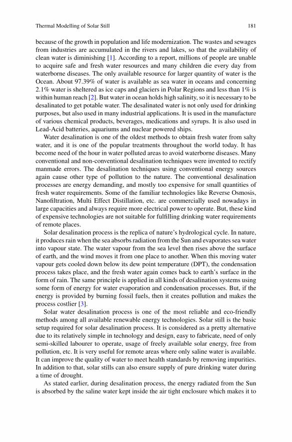
Thermal Modelling of Solar Still 181
because of the growth in population and life modernization. The wastes and sewagesfrom industries are accumulated in the rivers and lakes, so that the availability ofclean water is diminishing [1]. According to a report, millions of people are unableto acquire safe and fresh water resources and many children die every day fromwaterborne diseases. The only available resource for larger quantity of water is theOcean. About 97.39% of water is available as sea water in oceans and concerning2.1% water is sheltered as ice caps and glaciers in Polar Regions and less than 1% iswithin human reach [2]. But water in ocean holds high salinity, so it is necessary to bedesalinated to get potable water. The desalinated water is not only used for drinkingpurposes, but also used in many industrial applications. It is used in the manufactureof various chemical products, beverages, medications and syrups. It is also used inLead-Acid batteries, aquariums and nuclear powered ships.
Water desalination is one of the oldest methods to obtain fresh water from saltywater, and it is one of the popular treatments throughout the world today. It hasbecome need of the hour in water polluted areas to avoid waterborne diseases. Manyconventional and non-conventional desalination techniques were invented to rectifymanmade errors. The desalination techniques using conventional energy sourcesagain cause other type of pollution to the nature. The conventional desalinationprocesses are energy demanding, and mostly too expensive for small quantities offresh water requirements. Some of the familiar technologies like Reverse Osmosis,Nanofiltration, Multi Effect Distillation, etc. are commercially used nowadays inlarge capacities and always require more electrical power to operate. But, these kindof expensive technologies are not suitable for fulfilling drinking water requirementsof remote places.
Solar desalination process is the replica of nature’s hydrological cycle. In nature,it produces rain when the sea absorbs radiation from the Sun and evaporates sea waterinto vapour state. The water vapour from the sea level then rises above the surfaceof earth, and the wind moves it from one place to another. When this moving watervapour gets cooled down below its dew point temperature (DPT), the condensationprocess takes place, and the fresh water again comes back to earth’s surface in theform of rain. The same principle is applied in all kinds of desalination systems usingsome form of energy for water evaporation and condensation processes. But, if theenergy is provided by burning fossil fuels, then it creates pollution and makes theprocess costlier [3].
Solar water desalination process is one of the most reliable and eco-friendlymethods among all available renewable energy technologies. Solar still is the basicsetup required for solar desalination process. It is considered as a pretty alternativedue to its relatively simple in technology and design, easy to fabricate, need of onlysemi-skilled labourer to operate, usage of freely available solar energy, free frompollution, etc. It is very useful for remote areas where only saline water is available.It can improve the quality of water to meet health standards by removing impurities.In addition to that, solar stills can also ensure supply of pure drinking water duringa time of drought.
As stated earlier, during desalination process, the energy radiated from the Sunis absorbed by the saline water kept inside the air tight enclosure which makes it to
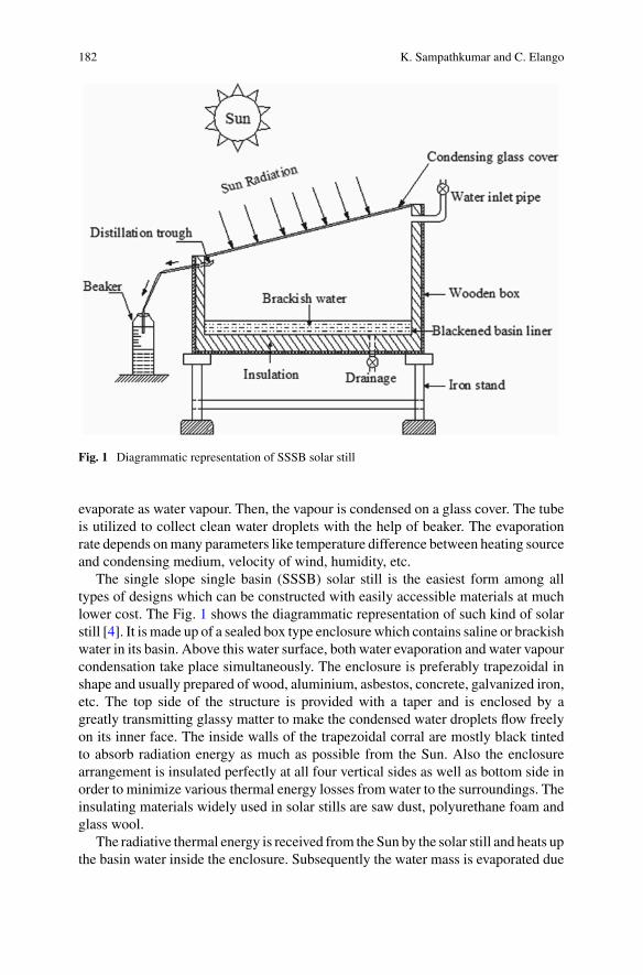
182 K. Sampathkumar and C. Elango
Fig. 1 Diagrammatic representation of SSSB solar still
evaporate as water vapour. Then, the vapour is condensed on a glass cover. The tubeis utilized to collect clean water droplets with the help of beaker. The evaporationrate depends onmany parameters like temperature difference between heating sourceand condensing medium, velocity of wind, humidity, etc.
The single slope single basin (SSSB) solar still is the easiest form among alltypes of designs which can be constructed with easily accessible materials at muchlower cost. The Fig. 1 shows the diagrammatic representation of such kind of solarstill [4]. It is made up of a sealed box type enclosure which contains saline or brackishwater in its basin. Above this water surface, both water evaporation and water vapourcondensation take place simultaneously. The enclosure is preferably trapezoidal inshape and usually prepared of wood, aluminium, asbestos, concrete, galvanized iron,etc. The top side of the structure is provided with a taper and is enclosed by agreatly transmitting glassy matter to make the condensed water droplets flow freelyon its inner face. The inside walls of the trapezoidal corral are mostly black tintedto absorb radiation energy as much as possible from the Sun. Also the enclosurearrangement is insulated perfectly at all four vertical sides as well as bottom side inorder to minimize various thermal energy losses from water to the surroundings. Theinsulating materials widely used in solar stills are saw dust, polyurethane foam andglass wool.
The radiative thermal energy is received from the Sun by the solar still and heats upthe basin water inside the enclosure. Subsequently the water mass is evaporated due
Thermal Modelling of Solar Still 183
to this heating process which in turn forms water vapour in the air space providedinside the structure. The air–water vapour mixture nearer to the surface of basinwater has high temperature and low density compared with the air–water vapourmixture nearer to the top glass cover. This automatically stimulates the heat transferprocess (convection) among liquid and solid surfaces. The air–water vapour mixturerises towards the glass cover and then condenses partially at its inner surface. Thecondensate produced in the form of droplets flows through a conduit attached withthe lower part of the glass cover and is then finally collected in a beaker through a hoseconnected with that conduit. In addition to that, some provisions are made to decantthe salty water into the enclosed space and also to clean the contaminants settleddown in the basin periodically. The entire set-up generally faces South directionon a wooden or iron stand in order to collect maximum possible radiative energythroughout the day from the Sun.
The solar stills are generally categorized as either passive or active systems basedon its energy input mechanism. In passive system, Sun is the only source for thermalenergy in the form of radiation to heat the water available in the basin. But in activesystem, some kind of external devices like solar collectors, solar concentrators, pho-tovoltaic/thermal systems, etc. are used to afford added heat energy to evaporatewater in the basin [5–8].
For improving, solar still performance, many theoretical as well as experimentalattempts have been carried out during the past. Several design and operational modi-fications have been explored for the improvement of solar still performance by manyresearchers. But the experimental research needs comparatively longer duration withhigh investment cost. Also, due to intricacy in fabrication and operation, the exper-imental research works do not provide any flexibility to the researchers during theanalysis of solar still performance. Hence, it is suggested that the theoretical investi-gations are found to be more convenient and highly suitable method to envisage theinfluencing parameters of the still for its efficient operation and utilization.
In theoretical investigations, developing a thermal model is one of the most suc-cessful methods to envisage the concert of any kind of thermal arrangement. In caseof solar still, energy balances between its components are used to develop the thermalmodelling. Also, these thermal models are able to present a clear-cut understandingon the recital of solar stills under authentic working situation. In this context, numer-ous theoretical models were developed by various investigators, namely Dunkle,Adhikari, Kumar and Tiwari, etc. and successfully tested for their suitability. Eventhough various designs have been developed during past few decades, single basinsingle slope solar still has been widely used for its simplest structure and ease ofoperation. This chapter aimed to present the basics for the development of thermalmodelling for such kind of solar still [9–12].
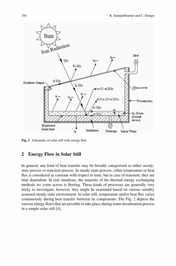
184 K. Sampathkumar and C. Elango
Fig. 2 Schematic of solar still with energy flow
2 Energy Flow in Solar Still
In general, any kind of heat transfer may be broadly categorized as either steady-state process or transient process. In steady-state process, either temperature or heatflux is considered as constant with respect to time; but in case of transient, they aretime dependent. In real situations, the majority of the thermal energy exchangingmethods we come across is fleeting. These kinds of processes are generally verytricky to investigate; however, they might be examined based on various suitablyassumed steady-state environment. In solar still, temperature and/or heat flux variescontinuously during heat transfer between its components. The Fig. 2 depicts thevarious energy flows that are possible to take place during water desalination processin a simple solar still [4].
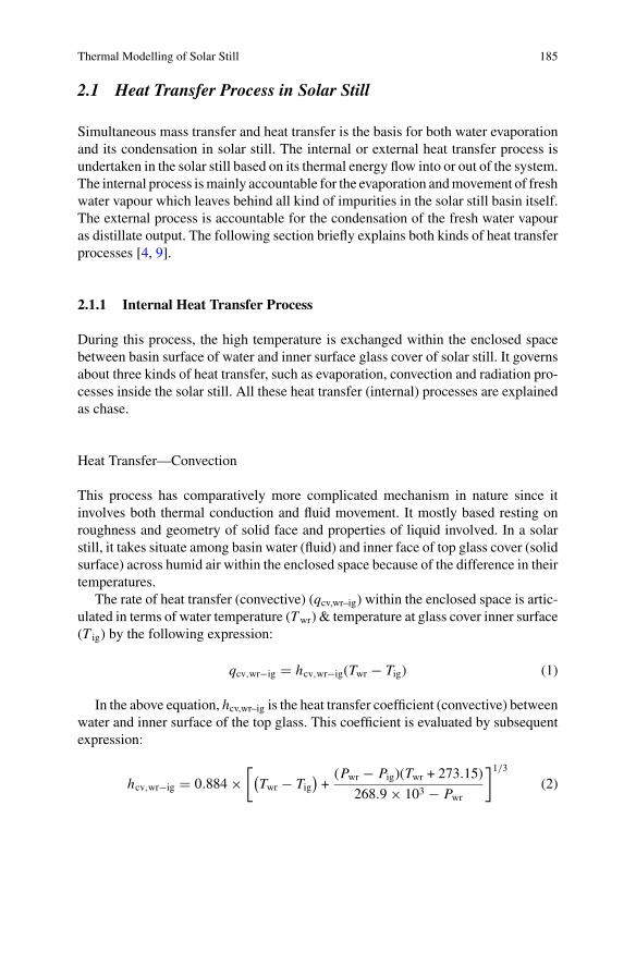
Thermal Modelling of Solar Still 185
2.1 Heat Transfer Process in Solar Still
Simultaneous mass transfer and heat transfer is the basis for both water evaporationand its condensation in solar still. The internal or external heat transfer process isundertaken in the solar still based on its thermal energy flow into or out of the system.The internal process ismainly accountable for the evaporation andmovement of freshwater vapour which leaves behind all kind of impurities in the solar still basin itself.The external process is accountable for the condensation of the fresh water vapouras distillate output. The following section briefly explains both kinds of heat transferprocesses [4, 9].
2.1.1 Internal Heat Transfer Process
During this process, the high temperature is exchanged within the enclosed spacebetween basin surface of water and inner surface glass cover of solar still. It governsabout three kinds of heat transfer, such as evaporation, convection and radiation pro-cesses inside the solar still. All these heat transfer (internal) processes are explainedas chase.
Heat Transfer—Convection
This process has comparatively more complicated mechanism in nature since itinvolves both thermal conduction and fluid movement. It mostly based resting onroughness and geometry of solid face and properties of liquid involved. In a solarstill, it takes situate among basin water (fluid) and inner face of top glass cover (solidsurface) across humid air within the enclosed space because of the difference in theirtemperatures.
The rate of heat transfer (convective) (qcv,wr–ig) within the enclosed space is artic-ulated in terms of water temperature (Twr) & temperature at glass cover inner surface(T ig) by the following expression:
qcv,wr−ig � hcv,wr−ig(Twr − Tig) (1)
In the above equation, hcv,wr–ig is the heat transfer coefficient (convective) betweenwater and inner surface of the top glass. This coefficient is evaluated by subsequentexpression:
hcv,wr−ig � 0.884 ×[(Twr − Tig
)+(Pwr − Pig)(Twr + 273.15)
268.9 × 10³ − Pwr
]1/3
(2)
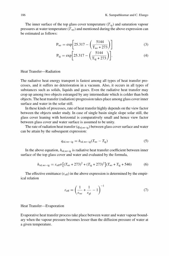
186 K. Sampathkumar and C. Elango
The inner surface of the top glass cover temperature (T ig) and saturation vapourpressures at water temperature (Twr) and mentioned during the above expression canbe estimated as follows:
Pwr � exp
[25.317 −
(5144
Twr + 273
)](3)
Pig � exp
[25.317 −
(5144
Tig + 273
)]. (4)
Heat Transfer—Radiation
The radiative heat energy transport is fastest among all types of heat transfer pro-cesses, and it suffers no deterioration in a vacuum. Also, it occurs in all types ofsubstances such as solids, liquids and gases. Even the radiative heat transfer maycrop up among two objects estranged by any intermediate which is colder than bothobjects. The heat transfer (radiation) progression takes place among glass cover innersurface and water in the solar still.
In these kinds of processes, rate of heat transfer highly depends on the view factorbetween the objects under study. In case of single basin single slope solar still, theglass cover leaning with horizontal is comparatively small and hence view factorbetween glass cover and water surface is assumed to be unity.
The rate of radiation heat transfer (qrd,wr–ig) between glass cover surface and watercan be attain by the subsequent expression:
qrd,wr−ig � hrd,wr−ig(Twr − Tig) (5)
In the above equation, hrd,wr–ig is radiative heat transfer coefficient between innersurface of the top glass cover and water and evaluated by the formula,
hrd,wr−ig � εeffσ[(Twr + 273)2 + (Tig + 273)2
](Twr + Tig + 546) (6)
The effective emittance (εeff) in the above expression is determined by the empir-ical relation
εeff �(
1
εwr+
1
εgl− 1
)−1
(7)
Heat Transfer—Evaporation
Evaporative heat transfer process take place between water and water vapour bound-ary when the vapour pressure becomes lesser than the diffusion pressure of water ata given temperature.
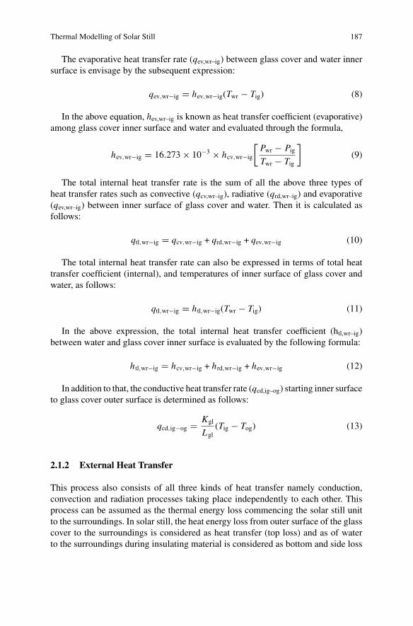
Thermal Modelling of Solar Still 187
The evaporative heat transfer rate (qev,wr–ig) between glass cover and water innersurface is envisage by the subsequent expression:
qev,wr−ig � hev,wr−ig(Twr − Tig) (8)
In the above equation, hev,wr–ig is known as heat transfer coefficient (evaporative)among glass cover inner surface and water and evaluated through the formula,
hev,wr−ig � 16.273 × 10⁻³ × hcv,wr−ig
[Pwr − PigTwr − Tig
](9)
The total internal heat transfer rate is the sum of all the above three types ofheat transfer rates such as convective (qcv,wr–ig), radiative (qrd,wr–ig) and evaporative(qev,wr–ig) between inner surface of glass cover and water. Then it is calculated asfollows:
qtl,wr−ig � qcv,wr−ig + qrd,wr−ig + qev,wr−ig (10)
The total internal heat transfer rate can also be expressed in terms of total heattransfer coefficient (internal), and temperatures of inner surface of glass cover andwater, as follows:
qtl,wr−ig � htl,wr−ig(Twr − Tig) (11)
In the above expression, the total internal heat transfer coefficient (htl,wr–ig)between water and glass cover inner surface is evaluated by the following formula:
htl,wr−ig � hcv,wr−ig + hrd,wr−ig + hev,wr−ig (12)
In addition to that, the conductive heat transfer rate (qcd,ig–og) starting inner surfaceto glass cover outer surface is determined as follows:
qcd,ig−og � Kgl
Lgl(Tig − Tog) (13)
2.1.2 External Heat Transfer
This process also consists of all three kinds of heat transfer namely conduction,convection and radiation processes taking place independently to each other. Thisprocess can be assumed as the thermal energy loss commencing the solar still unitto the surroundings. In solar still, the heat energy loss from outer surface of the glasscover to the surroundings is considered as heat transfer (top loss) and as of waterto the surroundings during insulating material is considered as bottom and side loss
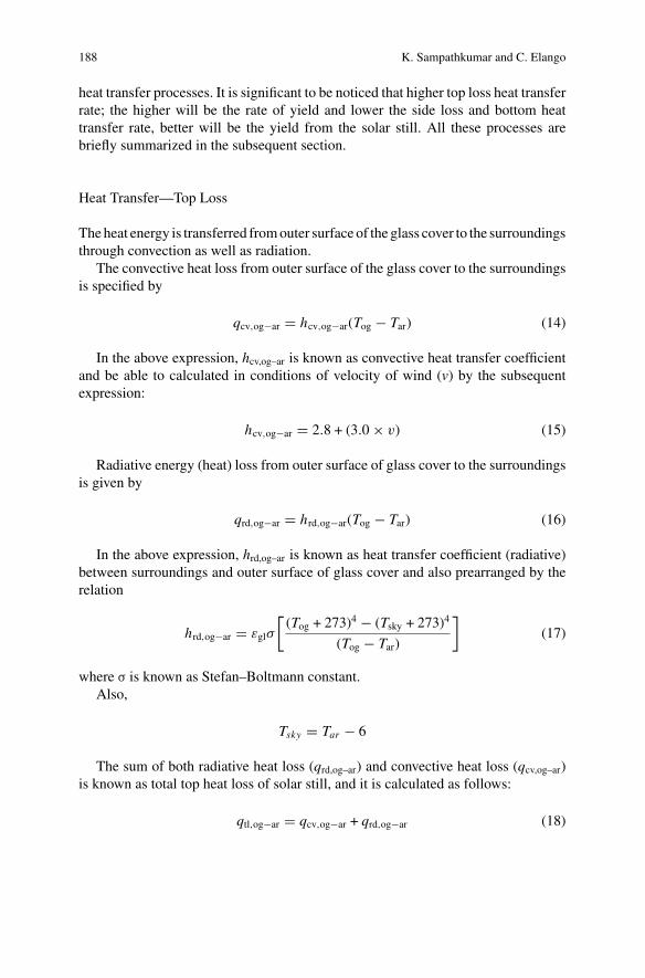
188 K. Sampathkumar and C. Elango
heat transfer processes. It is significant to be noticed that higher top loss heat transferrate; the higher will be the rate of yield and lower the side loss and bottom heattransfer rate, better will be the yield from the solar still. All these processes arebriefly summarized in the subsequent section.
Heat Transfer—Top Loss
Theheat energy is transferred fromouter surface of the glass cover to the surroundingsthrough convection as well as radiation.
The convective heat loss from outer surface of the glass cover to the surroundingsis specified by
qcv,og−ar � hcv,og−ar(Tog − Tar) (14)
In the above expression, hcv,og–ar is known as convective heat transfer coefficientand be able to calculated in conditions of velocity of wind (v) by the subsequentexpression:
hcv,og−ar � 2.8 + (3.0 × v) (15)
Radiative energy (heat) loss from outer surface of glass cover to the surroundingsis given by
qrd,og−ar � hrd,og−ar(Tog − Tar) (16)
In the above expression, hrd,og–ar is known as heat transfer coefficient (radiative)between surroundings and outer surface of glass cover and also prearranged by therelation
hrd,og−ar � εglσ
[(Tog + 273)4 − (Tsky + 273)4
(Tog − Tar)
](17)
where σ is known as Stefan–Boltmann constant.Also,
Tsky � Tar − 6
The sum of both radiative heat loss (qrd,og–ar) and convective heat loss (qcv,og–ar)is known as total top heat loss of solar still, and it is calculated as follows:
qtl,og−ar � qcv,og−ar + qrd,og−ar (18)
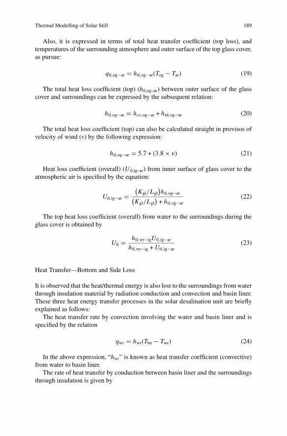
Thermal Modelling of Solar Still 189
Also, it is expressed in terms of total heat transfer coefficient (top loss), andtemperatures of the surrounding atmosphere and outer surface of the top glass cover,as pursue:
qtl,og−ar � htl,og−ar(Tog − Tar) (19)
The total heat loss coefficient (top) (htl,og–ar) between outer surface of the glasscover and surroundings can be expressed by the subsequent relation:
htl,og−ar � hcv,og−ar + hrd,og−ar (20)
The total heat loss coefficient (top) can also be calculated straight in provisos ofvelocity of wind (v) by the following expression:
htl,og−ar � 5.7 + (3.8 × v) (21)
Heat loss coefficient (overall) (U tl,ig–ar) from inner surface of glass cover to theatmospheric air is specified by the equation:
Utl,ig−ar �(Kgl/Lgl
)htl,og−ar(
Kgl/Lgl)+ htl,og−ar
(22)
The top heat loss coefficient (overall) from water to the surroundings during theglass cover is obtained by
Utl � htl,wr−igUtl,ig−ar
htl,wr−ig +Utl,ig−ar(23)
Heat Transfer—Bottom and Side Loss
It is observed that the heat/thermal energy is also lost to the surroundings from waterthrough insulation material by radiation conduction and convection and basin liner.These three heat energy transfer processes in the solar desalination unit are brieflyexplained as follows:
The heat transfer rate by convection involving the water and basin liner and isspecified by the relation
qwr � hwr(Tbn − Twr) (24)
In the above expression, “hwr” is known as heat transfer coefficient (convective)from water to basin liner.
The rate of heat transfer by conduction between basin liner and the surroundingsthrough insulation is given by
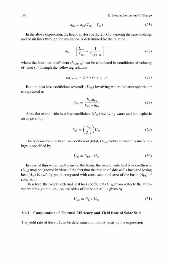
190 K. Sampathkumar and C. Elango
qbn � hbn(Tbn − Tar ) (25)
In the above expression, the heat transfer coefficient (hbn) among the surroundingsand basin liner through the insulation is determined by the relation
hbn �[L ins
Kins+
1
htl,bn−ar
]−1
(26)
where the heat loss coefficient (htl,bn–ar) can be calculated in conditions of velocityof wind (v) through the following relation
htl,bn−ar � 5.7 + (3.8 × v) (27)
Bottom heat loss coefficient (overall) (Ubn) involving water and atmospheric airis expressed as
Ubn � hwrhbnhwr + hbn
(28)
Also, the overall side heat loss coefficient (Uss) involving water and atmosphericair is given by
Uss �(Ass
Abn
)Ubn (29)
The bottom and side heat loss coefficient (total) (Ubs) between water to surround-ings is specified by
Ubs � Ubn +Uss (30)
In case of thin water depths inside the basin, the overall side heat loss coefficient(Uss) may be ignored in view of the fact that the region of side walls involved losingheat (Ass) is awfully petite compared with cross-sectional area of the basin (Abn) ofsolar still.
Therefore, the overall external heat loss coefficient (ULS) from water to the atmo-sphere through bottom, top and sides of the solar still is given by
ULS � Utl +Ubs (31)
2.1.3 Computation of Thermal Efficiency and Yield Rate of Solar Still
The yield rate of the still can be determined on hourly basis by the expression
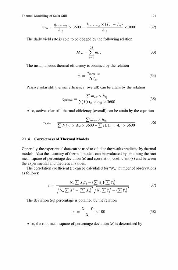
Thermal Modelling of Solar Still 191
mew � qev,wr−ig
hfg× 3600 � hev,wr−ig × (Twr − Tig)
hfg× 3600 (32)
The daily yield rate is able to be dogged by the following relation
Mew �24∑i�1
mew (33)
The instantaneous thermal efficiency is obtained by the relation
ηi � qev,wr−ig
I (t)sr(34)
Passive solar still thermal efficiency (overall) can be attain by the relation
ηpassive �∑
mew × hfg∑I (t)sr × Asl × 3600
(35)
Also, active solar still thermal efficiency (overall) can be attain by the equation
ηactive �∑
mew × hfg∑I (t)sr × Asl × 3600 +
∑I (t)cr × Acr × 3600
(36)
2.1.4 Correctness of Thermal Models
Generally, the experiential data canbeused to validate the results predicted by thermalmodels. Also the accuracy of thermal models can be evaluated by obtaining the rootmean square of percentage deviation (e) and correlation coefficient (r) and betweenthe experimental and theoretical values.
The correlation coefficient (r) can be calculated for “No” number of observationsas follows:
r � No∑
X jYj −(∑
X j)(∑
Yj)
√No
∑X2j − (∑
X j)2√
No∑
Y 2j − (∑
Yj)2 (37)
The deviation (ej) percentage is obtained by the relation
ej � X j − YjX j
× 100 (38)
Also, the root mean square of percentage deviation (e) is determined by
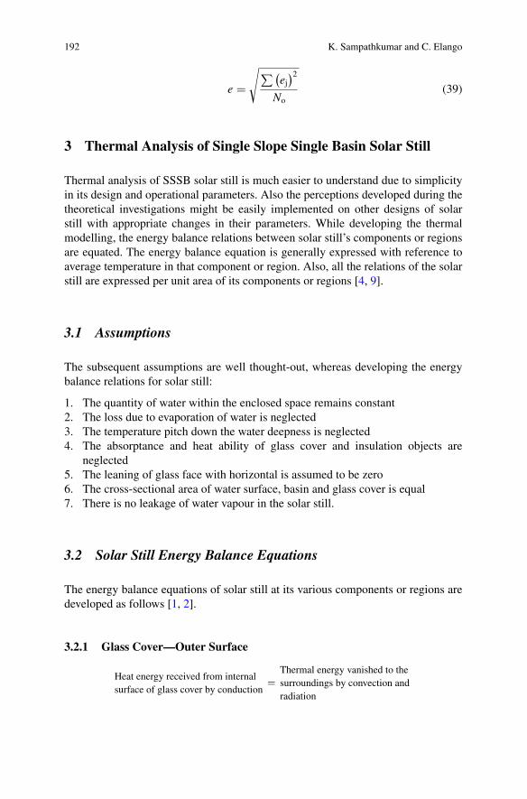
192 K. Sampathkumar and C. Elango
e �√∑(
ej)2
No(39)
3 Thermal Analysis of Single Slope Single Basin Solar Still
Thermal analysis of SSSB solar still is much easier to understand due to simplicityin its design and operational parameters. Also the perceptions developed during thetheoretical investigations might be easily implemented on other designs of solarstill with appropriate changes in their parameters. While developing the thermalmodelling, the energy balance relations between solar still’s components or regionsare equated. The energy balance equation is generally expressed with reference toaverage temperature in that component or region. Also, all the relations of the solarstill are expressed per unit area of its components or regions [4, 9].
3.1 Assumptions
The subsequent assumptions are well thought-out, whereas developing the energybalance relations for solar still:
1. The quantity of water within the enclosed space remains constant2. The loss due to evaporation of water is neglected3. The temperature pitch down the water deepness is neglected4. The absorptance and heat ability of glass cover and insulation objects are
neglected5. The leaning of glass face with horizontal is assumed to be zero6. The cross-sectional area of water surface, basin and glass cover is equal7. There is no leakage of water vapour in the solar still.
3.2 Solar Still Energy Balance Equations
The energy balance equations of solar still at its various components or regions aredeveloped as follows [1, 2].
3.2.1 Glass Cover—Outer Surface
Heat energy received from internalsurface of glass cover by conduction
�Thermal energy vanished to thesurroundings by convection andradiation
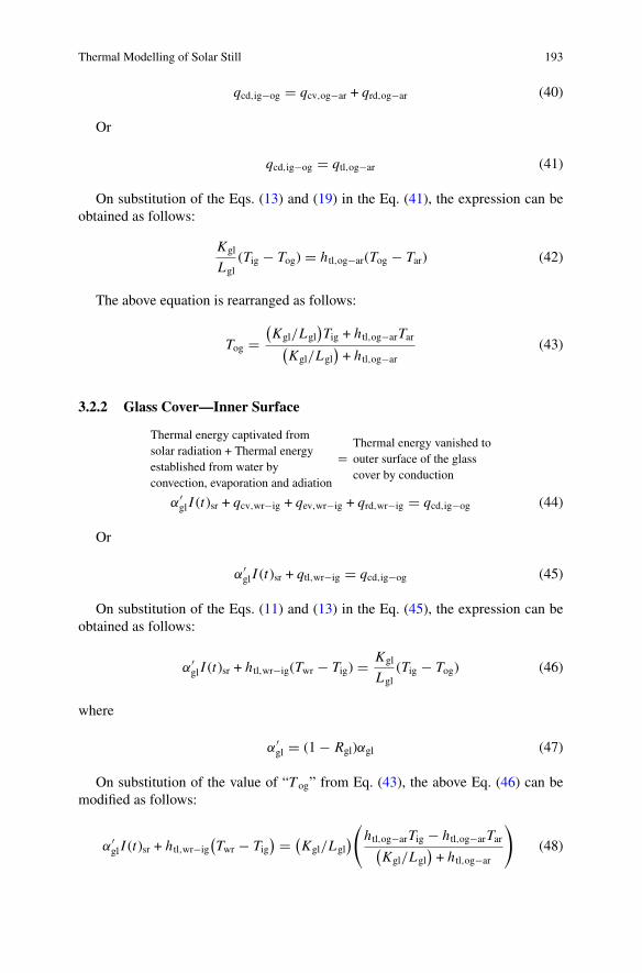
Thermal Modelling of Solar Still 193
qcd,ig−og � qcv,og−ar + qrd,og−ar (40)
Or
qcd,ig−og � qtl,og−ar (41)
On substitution of the Eqs. (13) and (19) in the Eq. (41), the expression can beobtained as follows:
Kgl
Lgl(Tig − Tog) � htl,og−ar(Tog − Tar) (42)
The above equation is rearranged as follows:
Tog �(Kgl/Lgl
)Tig + htl,og−arTar(
Kgl/Lgl)+ htl,og−ar
(43)
3.2.2 Glass Cover—Inner Surface
Thermal energy captivated fromsolar radiation + Thermal energyestablished from water byconvection, evaporation and adiation
�Thermal energy vanished toouter surface of the glasscover by conduction
α′gl I (t)sr + qcv,wr−ig + qev,wr−ig + qrd,wr−ig � qcd,ig−og (44)
Or
α′gl I (t)sr + qtl,wr−ig � qcd,ig−og (45)
On substitution of the Eqs. (11) and (13) in the Eq. (45), the expression can beobtained as follows:
α′gl I (t)sr + htl,wr−ig(Twr − Tig) � Kgl
Lgl(Tig − Tog) (46)
where
α′gl � (1 − Rgl)αgl (47)
On substitution of the value of “T og” from Eq. (43), the above Eq. (46) can bemodified as follows:
α′gl I (t)sr + htl,wr−ig
(Twr − Tig
) � (Kgl/Lgl
)(htl,og−arTig − htl,og−arTar(Kgl/Lgl
)+ htl,og−ar
)(48)
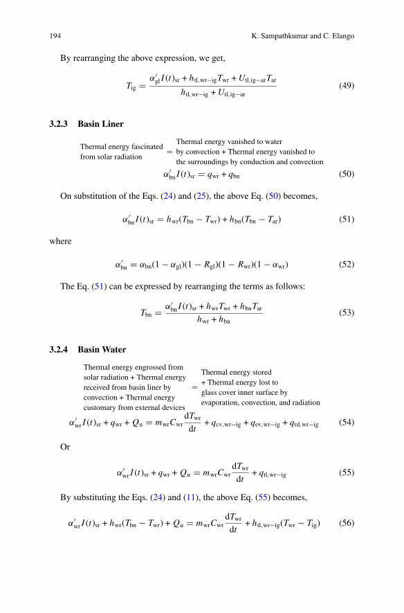
194 K. Sampathkumar and C. Elango
By rearranging the above expression, we get,
Tig � α′gl I (t)sr + htl,wr−igTwr +Utl,ig−arTar
htl,wr−ig +Utl,ig−ar(49)
3.2.3 Basin Liner
Thermal energy fascinatedfrom solar radiation
�Thermal energy vanished to waterby convection + Thermal energy vanished tothe surroundings by conduction and convection
α′bn I (t)sr � qwr + qbn (50)
On substitution of the Eqs. (24) and (25), the above Eq. (50) becomes,
α′bn I (t)sr � hwr(Tbn − Twr) + hbn(Tbn − Tar) (51)
where
α′bn � αbn(1 − αgl)(1 − Rgl)(1 − Rwr)(1 − αwr) (52)
The Eq. (51) can be expressed by rearranging the terms as follows:
Tbn � α′bn I (t)sr + hwrTwr + hbnTar
hwr + hbn(53)
3.2.4 Basin Water
Thermal energy engrossed fromsolar radiation + Thermal energyreceived from basin liner byconvection + Thermal energycustomary from external devices
�Thermal energy stored+ Thermal energy lost toglass cover inner surface byevaporation, convection, and radiation
α′wr I (t)sr + qwr + Qu � mwrCwr
dTwrdt
+ qcv,wr−ig + qev,wr−ig + qrd,wr−ig (54)
Or
α′wr I (t)sr + qwr + Qu � mwrCwr
dTwrdt
+ qtl,wr−ig (55)
By substituting the Eqs. (24) and (11), the above Eq. (55) becomes,
α′wr I (t)sr + hwr(Tbn − Twr) + Qu � mwrCwr
dTwrdt
+ htl,wr−ig(Twr − Tig) (56)
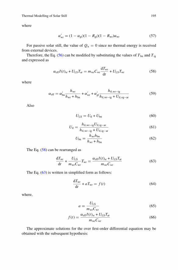
Thermal Modelling of Solar Still 195
where
α′wr � (1 − αgl)(1 − Rgl)(1 − Rwr)αwr (57)
For passive solar still, the value of Qu � 0 since no thermal energy is receivedfrom external devices.
Therefore, the Eq. (56) can be modified by substituting the values of T bn and T ig
and expressed as
αeff I (t)sr +ULSTar � mwrCwrdTwrdt
+ULSTwr (58)
where
αeff � α′bn
hwrhwr + hbn
+ α′wr + α′
gl
htl,wr−ig
htl,wr−ig +Utl,og−ar(59)
Also
ULS � Utl +Ubn (60)
Utl � htl,wr−igUtl,ig−ar
htl,wr−ig +Utl,ig−ar(61)
Ubn � hwrhbnhwr + hbn
(62)
The Eq. (58) can be rearranged as
dTwrdt
+ULS
mwrCwrTwr � αeff I (t)sr +ULSTar
mwrCwr(63)
The Eq. (63) is written in simplified form as follows:
dTwrdt
+ aTwr � f (t) (64)
where,
a � ULS
mwrCwr(65)
f (t) � αeff I (t)sr +ULSTarmwrCwr
(66)
The approximate solutions for the over first-order differential equation may beobtained with the subsequent hypothesis:
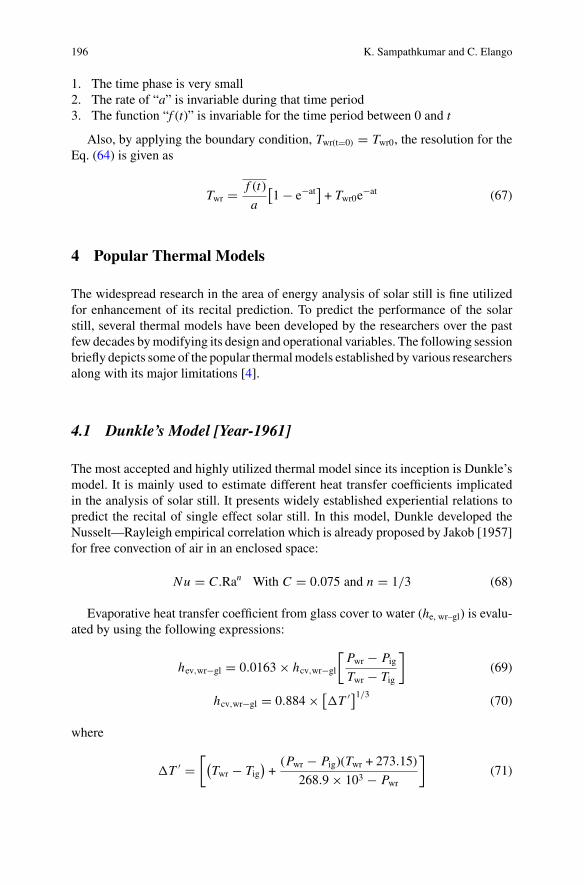
196 K. Sampathkumar and C. Elango
1. The time phase is very small2. The rate of “a” is invariable during that time period3. The function “f (t)” is invariable for the time period between 0 and t
Also, by applying the boundary condition, Twr(t�0) � Twr0, the resolution for theEq. (64) is given as
Twr � f (t)
a
[1 − e−at
]+ Twr0e
−at (67)
4 Popular Thermal Models
The widespread research in the area of energy analysis of solar still is fine utilizedfor enhancement of its recital prediction. To predict the performance of the solarstill, several thermal models have been developed by the researchers over the pastfew decades bymodifying its design and operational variables. The following sessionbriefly depicts some of the popular thermalmodels established by various researchersalong with its major limitations [4].
4.1 Dunkle’s Model [Year-1961]
The most accepted and highly utilized thermal model since its inception is Dunkle’smodel. It is mainly used to estimate different heat transfer coefficients implicatedin the analysis of solar still. It presents widely established experiential relations topredict the recital of single effect solar still. In this model, Dunkle developed theNusselt—Rayleigh empirical correlation which is already proposed by Jakob [1957]for free convection of air in an enclosed space:
Nu � C.Ran With C � 0.075 and n � 1/3 (68)
Evaporative heat transfer coefficient from glass cover to water (he, wr–gl) is evalu-ated by using the following expressions:
hev,wr−gl � 0.0163 × hcv,wr−gl
[Pwr − PigTwr − Tig
](69)
hcv,wr−gl � 0.884 × [T ′]1/3 (70)
where
T ′ �[(Twr − Tig
)+(Pwr − Pig)(Twr + 273.15)
268.9 × 10³ − Pwr
](71)
Thermal Modelling of Solar Still 197
The limitations of Dunkle’s model are given as follows:
1. The empirical correlationswere initially developed for free convective heat trans-fer of air devoid of considering evaporation
2. The difference in temperature range between evaporative and condensing facadeis assumed as 17 °C
3. The moist air’s thermo-physical properties are assumed at Twr ≈ 50 °C4. The evaporation and condensation surfaces are parallel5. The attribute length between evaporation and condensation surfaces is neglected
It is experiential from the investigations that the Dunkle’s model was widelyaccepted by many researchers for solar desalination process even in the workingsituation that are not declining under the limitations of that model.
4.2 Chen et al.’s Model [Year-1984]
Chen et al. developed a mathematical expression to estimate the convective heattransfer coefficient based on Rayleigh number in the range (3.5 × 10³ < Ra < 1 ×10⁶) which can be expressed as,
hcv,wr−gl � 0.2Ra0.26Kfg
df(72)
4.3 Clark’s Model [Year-1990]
In this model, the evaporative heat transfer rate from water to glass cover can beestimated as follows:
qev,wr−gl � (k ′/2)hcv,wr−gl(Pwr − Pig) (73)
where k ′ � 0.016273The Clark’s model is generally applicable when
1. The spacing among evaporation and condensation surfaces is huge2. The condensation and evaporation rates are equal; it is only possible for elevated
working temperature range of the desalination process (i.e. greater than 80 °C)
The Clark’s model was experimentally validated for the operating temperaturerange greater than 55 °C. The experiment was conducted in air-conditioned spacewhich supply high rate of heat transfer. But this is not possible in real operatingconditions of the still.
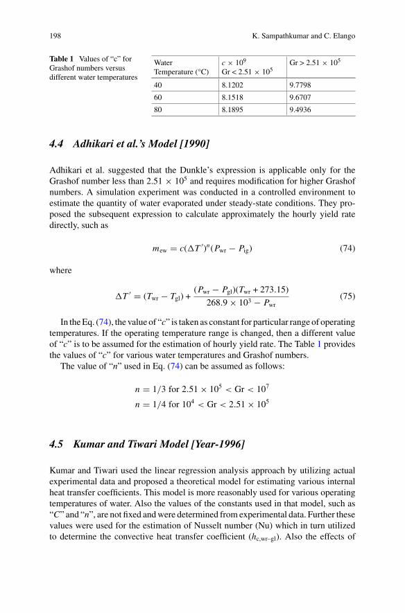
198 K. Sampathkumar and C. Elango
Table 1 Values of “c” forGrashof numbers versusdifferent water temperatures
WaterTemperature (°C)
c × 109
Gr < 2.51 × 10⁵Gr > 2.51 × 10⁵
40 8.1202 9.7798
60 8.1518 9.6707
80 8.1895 9.4936
4.4 Adhikari et al.’s Model [1990]
Adhikari et al. suggested that the Dunkle’s expression is applicable only for theGrashof number less than 2.51 × 10⁵ and requires modification for higher Grashofnumbers. A simulation experiment was conducted in a controlled environment toestimate the quantity of water evaporated under steady-state conditions. They pro-posed the subsequent expression to calculate approximately the hourly yield ratedirectly, such as
mew � c(T ′)n(Pwr − Pig) (74)
where
T ′ � (Twr − Tgl) +(Pwr − Pgl)(Twr + 273.15)
268.9 × 10³ − Pwr(75)
In theEq. (74), the value of “c” is taken as constant for particular range of operatingtemperatures. If the operating temperature range is changed, then a different valueof “c” is to be assumed for the estimation of hourly yield rate. The Table 1 providesthe values of “c” for various water temperatures and Grashof numbers.
The value of “n” used in Eq. (74) can be assumed as follows:
n � 1/3 for 2.51 × 10⁵ < Gr < 107
n � 1/4 for 104 < Gr < 2.51 × 10⁵
4.5 Kumar and Tiwari Model [Year-1996]
Kumar and Tiwari used the linear regression analysis approach by utilizing actualexperimental data and proposed a theoretical model for estimating various internalheat transfer coefficients. This model is more reasonably used for various operatingtemperatures of water. Also the values of the constants used in that model, such as“C” and “n”, are not fixed andwere determined from experimental data. Further thesevalues were used for the estimation of Nusselt number (Nu) which in turn utilizedto determine the convective heat transfer coefficient (hc,wr–gl). Also the effects of
Thermal Modelling of Solar Still 199
orientation of the condenser cover, cavity of the solar still and range of operatingtemperature were incorporated in the model.
The Nusselt number (Nu) expression to guesstimate the convective heat transfercoefficient is given by
Nu � hcv,wr−gldfKfg
� C(Gr Pr)n (76)
Or
hcv,wr−gl � Kfg
dfC(Gr Pr)n (77)
where
Gr � βgd3f ρ
2fg(Twr − Tig)
μ2fg
(78)
Pr � μ f gCp, f g
K f g(79)
The rate of yield during time “t” is estimated by
mew � 0.01623
hlg× Kfg
df× C(Gr Pr)n × (Pwr − Pig) × Abn × t (80)
In the above expression, the values of the constants “C” and “n” are calculatedfrom actual experimental data and governed by the subsequent relations:
C � exp(C0) And
n � m
where,
C0 �
(No∑i�1
yi
)(No∑i�1
x2i
)−
(No∑i�1
xi
)(No∑i�1
xi yi
)
No
(No∑i�1
x2i
)−
(No∑i�1
xi
)2 (81)
m �No
(No∑i�1
xi yi
)−
(No∑i�1
xi
)(No∑i�1
yi
)
No
(No∑i�1
x2i
)−
(No∑i�1
xi
)2 (82)
200 K. Sampathkumar and C. Elango
From above expressions, it is noticed that “No” is the number of observations,and the values of “x” and “y” are obtained from actual experimental data.
4.6 Zheng Hongfei et al.’s Model [Year-2001]
Zheng Hongfei et al. proposed a minor correction in the phrase suggested by Chenet al. to estimate the internal convective heat transfer coefficient which is given asfollows:
hcv,wr−gl � 0.2(Rac)0.26 Kfg
df(83)
where
Rac � d3f ρfggβ
μfgαfgT ′′ (84)
Also
T ′′ �[(
Twr − Tig)+(Pwr − Pig)(Twr + 273.15)
MarPtlMar−Mwr
− Pwr
](85)
In the above Eq. (84), the value of “αfg” stands for humid air’s thermal diffusivity.
4.7 Tsilingiris Model [Year-2007]
A sophisticated model was proposed by Tsilingiris to represent the methods forfirst-order estimation of humid air’s thermo-physical properties. Tsilingiris utilizedthe belongings of dry air and water vapour mixture instead of inappropriate dry airproperties alone to evaluate various parameters of the solar still.
Convection heat transfer coefficient is evaluated by
hcv,wr−gl � CKmix
(gρmixβ
μmixdmix
)n[(Tsi − Tgl) +
Tsi(Pvs − Pvg)(Mar − Mvr)
MarPtl − Pvs(Mar − Mvr)
]n
(86)
The evaporation heat transfer coefficient is estimated by
hev,wr−gl � 1000hlghcv,wr−gl
Cp,ar
(Rcv)ar(Rcv)vr
Ptl(Ptl − Pvs)(Ptl − Pvg)
(87)
The yield rate per unit still area is expressed by
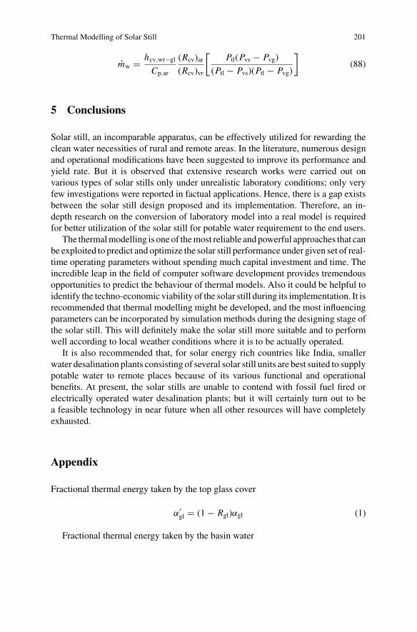
Thermal Modelling of Solar Still 201
mw � hcv,wr−gl
Cp,ar
(Rcv)ar(Rcv)vr
[Ptl(Pvs − Pvg)
(Ptl − Pvs)(Ptl − Pvg)
](88)
5 Conclusions
Solar still, an incomparable apparatus, can be effectively utilized for rewarding theclean water necessities of rural and remote areas. In the literature, numerous designand operational modifications have been suggested to improve its performance andyield rate. But it is observed that extensive research works were carried out onvarious types of solar stills only under unrealistic laboratory conditions; only veryfew investigations were reported in factual applications. Hence, there is a gap existsbetween the solar still design proposed and its implementation. Therefore, an in-depth research on the conversion of laboratory model into a real model is requiredfor better utilization of the solar still for potable water requirement to the end users.
The thermalmodelling is one of themost reliable andpowerful approaches that canbe exploited to predict and optimize the solar still performance under given set of real-time operating parameters without spending much capital investment and time. Theincredible leap in the field of computer software development provides tremendousopportunities to predict the behaviour of thermal models. Also it could be helpful toidentify the techno-economic viability of the solar still during its implementation. It isrecommended that thermal modelling might be developed, and the most influencingparameters can be incorporated by simulation methods during the designing stage ofthe solar still. This will definitely make the solar still more suitable and to performwell according to local weather conditions where it is to be actually operated.
It is also recommended that, for solar energy rich countries like India, smallerwater desalination plants consisting of several solar still units are best suited to supplypotable water to remote places because of its various functional and operationalbenefits. At present, the solar stills are unable to contend with fossil fuel fired orelectrically operated water desalination plants; but it will certainly turn out to bea feasible technology in near future when all other resources will have completelyexhausted.
Appendix
Fractional thermal energy taken by the top glass cover
α′gl � (1 − Rgl)αgl (1)
Fractional thermal energy taken by the basin water
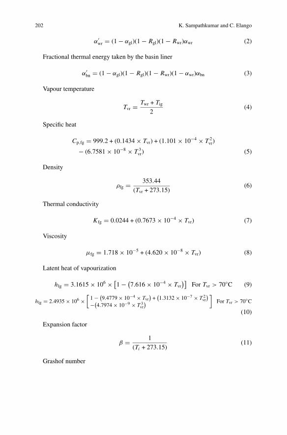
202 K. Sampathkumar and C. Elango
α′wr � (1 − αgl)(1 − Rgl)(1 − Rwr)αwr (2)
Fractional thermal energy taken by the basin liner
α′bn � (1 − αgl)(1 − Rgl)(1 − Rwr)(1 − αwr)αbn (3)
Vapour temperature
Tvr � Twr + Tig2
(4)
Specific heat
Cp,fg � 999.2 + (0.1434 × Tvr) + (1.101 × 10⁻⁴ × T 2vr)
− (6.7581 × 10⁻⁸ × T 3vr) (5)
Density
ρfg � 353.44
(Tvr + 273.15)(6)
Thermal conductivity
Kfg � 0.0244 + (0.7673 × 10⁻⁴ × Tvr) (7)
Viscosity
μfg � 1.718 × 10⁻⁵ + (4.620 × 10⁻⁸ × Tvr) (8)
Latent heat of vapourization
hlg � 3.1615 × 106 × [1 − (
7.616 × 10⁻⁴ × Tvr)]
For Tvr > 70◦C (9)
hlg � 2.4935 × 106 ×[1 − (
9.4779 × 10⁻⁴ × Tvr)+
(1.3132 × 10⁻⁷ × T 2
vr
)−(
4.7974 × 10⁻⁹ × T 3vr
)]
For Tvr > 70◦C
(10)
Expansion factor
β � 1
(Ti + 273.15)(11)
Grashof number
Thermal Modelling of Solar Still 203
Gr � βgd3f ρ
2fgT
μ2fg
(12)
Prandtl number
Pr � μfgCp,fg
Kfg(13)
References
1. Delyannis E (2003) Historic background of desalination and renewable energies. Sol Energy75:357–366
2. Sampathkumar K, Arjunan TV, Pitchandi P, Senthilkumar P (2010) Active solar distillation—adetailed review. Renew Sustain Energy Rev 14:1503–1526
3. Tiwari GN, Tiwari AK (2008) Solar distillation practice for water desalination systems. Ana-maya Publishers, New Delhi
4. Elango C, Gunasekaran N, Sampathkuar K (2015) Thermal models of solar still—a compre-hensive review. Renew Sustain Energy Rev 47:856–911
5. Karuppusamy Sampathkumar (2012) An experimental study on single basin solar still aug-mented with evacuated tubes. Thermal Sci 16(2):573–581
6. Abdel-Rehim Zeinab S, Lasheen Ashraf (2005) Improving the performance of solar desalina-tion systems. Renewable Energy 30:1955–1971
7. Tiwari GN, Dhiman NK (1991) Performance study of a high temperature distillation system.Energy Convers Manag 32(3):283–291
8. Sampathkumar K, Senthilkumar P (2012) Utilization of solar water heater in a single basinsolar still—an experimental study. Desalination 297:8–19
9. Sampathkumar K, Arjunan TV, Senthilkumar P (2011) Single basin solar still coupled withevacuated tubes—thermal modeling and experimental validation. Int Energy J 12:53–66
10. Mowla D, Karimi G (1995) Mathematical modelling of solar stills in Iran. Sol Energy55(5):389–393
11. Hongfei Zheng, Xiaoyan Zhang, Jing Zhang, Yuyuan Wu (2002) A group of improved heatand mass transfer correlations in solar stills. Energy Convers Manag 43:2469–2478
12. Shukla SK, Sorayan VPS (2005) Thermal modeling of solar stills: an experimental validation.Renewable Energy 30:683–699
Thermal Modeling of Pyramid Solar Still
Kuldeep H. Nayi and Kalpesh V. Modi
Abstract Solar desalination ismost encouraging an alternative solution for fulfillingthe requirement of clean and drinkable water in today’s world of energy crises andwater scarcity. Performance viability of solar desalination system is themain concernin this fast and advance world/life. Albeit, conventional solar still is cheap in cost,simple in construction, operation, and maintenance; its low productivity raises manyquestions on its worldwide applicability. Pyramid solar still is an innovative idea anddesign for the solar still that have higher productivity and many more other bene-fits over conventional solar still. Performance of solar still depends on operational,design and meteorological parameters. Thus, it is necessary to establish function thatdescribe the relationship, which can be utilized for optimization of system and fur-thermore to anticipate viability and competitiveness of system. Therefore, thermalmodeling (theoretical/mathematical model) of system plays vital role before actualimplementation of system as well as after implementation for performance evalua-tion and improvement. In this chapter, basic fundaments of pyramid solar still withits advantages over conventional solar still are described. Further, thermal model-ing (theoretical/mathematical model) is developed which can be useful to study thepyramid solar still.
Keywords Renewable energy · Solar desalination · Pyramid solar still · Thermalmodeling · Performance evaluation
K. H. Nayi (B)Mechanical Engineering Department, Government Engineering College,Valsad, Gujarat, Indiae-mail: [email protected]
K. V. ModiMechanical Engineering Department, Government Engineering College, Bhuj, Gujarat, India
© Springer Nature Singapore Pte Ltd. 2019A. Kumar and O. Prakash (eds.), Solar Desalination Technology,Green Energy and Technology, https://doi.org/10.1007/978-981-13-6887-5_9
205
206 K. H. Nayi and K. V. Modi
Nomenclature
English Letters
C Specific heat in kJ/kg Khfg Latent heat of evaporation of water in J/kgm Mass in kgQ Heat transfer rate in kWR ReflectivityT Temperature in K
Greeks
α Absorptivityε Emissivityη Efficiencyσ Stefan–Boltzmann constant
Subscripts
a Ambient airb Basinc Top Covercond Conductiveconv ConvectionDW Distillate waterevp Evaporationeff Effectivei Instantaneousrad Radiativet TotalTheo Theoreticalw Water
1 Introduction
Water is key element for sustain life on earth. It is also necessary for irrigation,agriculture, sanitation, energy generation, industrial production, etc. In twenty-first
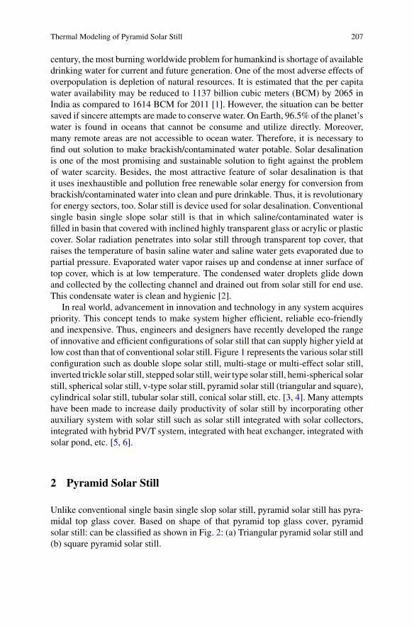
Thermal Modeling of Pyramid Solar Still 207
century, the most burning worldwide problem for humankind is shortage of availabledrinking water for current and future generation. One of the most adverse effects ofoverpopulation is depletion of natural resources. It is estimated that the per capitawater availability may be reduced to 1137 billion cubic meters (BCM) by 2065 inIndia as compared to 1614 BCM for 2011 [1]. However, the situation can be bettersaved if sincere attempts are made to conserve water. On Earth, 96.5% of the planet’swater is found in oceans that cannot be consume and utilize directly. Moreover,many remote areas are not accessible to ocean water. Therefore, it is necessary tofind out solution to make brackish/contaminated water potable. Solar desalinationis one of the most promising and sustainable solution to fight against the problemof water scarcity. Besides, the most attractive feature of solar desalination is thatit uses inexhaustible and pollution free renewable solar energy for conversion frombrackish/contaminated water into clean and pure drinkable. Thus, it is revolutionaryfor energy sectors, too. Solar still is device used for solar desalination. Conventionalsingle basin single slope solar still is that in which saline/contaminated water isfilled in basin that covered with inclined highly transparent glass or acrylic or plasticcover. Solar radiation penetrates into solar still through transparent top cover, thatraises the temperature of basin saline water and saline water gets evaporated due topartial pressure. Evaporated water vapor raises up and condense at inner surface oftop cover, which is at low temperature. The condensed water droplets glide downand collected by the collecting channel and drained out from solar still for end use.This condensate water is clean and hygienic [2].
In real world, advancement in innovation and technology in any system acquirespriority. This concept tends to make system higher efficient, reliable eco-friendlyand inexpensive. Thus, engineers and designers have recently developed the rangeof innovative and efficient configurations of solar still that can supply higher yield atlow cost than that of conventional solar still. Figure 1 represents the various solar stillconfiguration such as double slope solar still, multi-stage or multi-effect solar still,inverted trickle solar still, stepped solar still, weir type solar still, hemi-spherical solarstill, spherical solar still, v-type solar still, pyramid solar still (triangular and square),cylindrical solar still, tubular solar still, conical solar still, etc. [3, 4]. Many attemptshave been made to increase daily productivity of solar still by incorporating otherauxiliary system with solar still such as solar still integrated with solar collectors,integrated with hybrid PV/T system, integrated with heat exchanger, integrated withsolar pond, etc. [5, 6].
2 Pyramid Solar Still
Unlike conventional single basin single slop solar still, pyramid solar still has pyra-midal top glass cover. Based on shape of that pyramid top glass cover, pyramidsolar still: can be classified as shown in Fig. 2: (a) Triangular pyramid solar still and(b) square pyramid solar still.
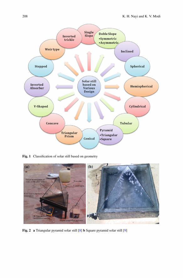
208 K. H. Nayi and K. V. Modi
Fig. 1 Classification of solar still based on geometry
Fig. 2 a Triangular pyramid solar still [8] b Square pyramid solar still [9]
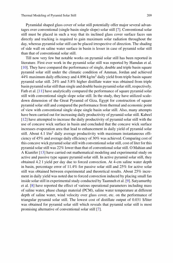
Thermal Modeling of Pyramid Solar Still 209
Pyramidal shaped glass cover of solar still potentially offer major several advan-tages over conventional (single basin single slope) solar still [7]. Conventional solarstill must be placed in such a way that its inclined glass cover surface faces sundirectly and tracking is required to gain maximum solar radiation throughout theday, whereas pyramid solar still can be placed irrespective of direction. The shadingof side wall on saline water surface in basin is lesser in case of pyramid solar stillthan that of conventional solar still.
Till now very few but notable works on pyramid solar still has been reported inliterature. First ever work in the pyramid solar still was reported by Hamdan et al.[10]. They have compared the performance of single, double and triple basin squarepyramid solar still under the climatic condition of Amman, Jordan and achieved44%maximum daily efficiency and 4.896 kg/m2 daily yield from triple basin squarepyramid solar still. 24% and 5.8% higher distillate water was obtained from triplebasin pyramid solar still than single and double basin pyramid solar still, respectively.Fath et al. [11] have analytically compared the performance of square pyramid solarstill with conventional single slope solar still. In the study, they have utilized scale-down dimension of the Great Pyramid of Giza, Egypt for construction of squarepyramid solar still and compared the performance from thermal and economic pointof view with conventional single slope single basin solar still. Also, many attemptshave been carried out for increasing daily productivity of pyramid solar still. Kabeel[12] have attempted to increase the daily productivity of pyramid solar still with theuse of concave wick surface in basin and concluded that the concave wick surfaceincreases evaporation area that lead to enhancement in daily yield of pyramid solarstill. About 4.1 l/m2 daily average productivity with maximum instantaneous effi-ciency of 45% and average daily efficiency of 30% was achieved. Comparing cost ofthis concave wick pyramid solar still with conventional solar still, cost of liter for thispyramid solar still was 22% lower than that of conventional solar still. OMahian andA Kianifer [13] have carried out mathematical modeling and experimental study onactive and passive type square pyramid solar still. In active pyramid solar still, theyobtained 4.2 l yield per day due to forced convection. At 4-cm saline water depthin basin, percentage error of 11.4% for passive solar still and 25% for active solarstill was obtained between experimental and theoretical results. About 25% incre-ment in daily yield was noted due to forced convection induced by placing small faninside solar still in experimental study conducted by Taamneh et al. [9]. Satyamurthyet al. [8] have reported the effect of various operational parameters including massof saline water, phase change material (PCM), saline water temperature at differentdepth of saline water, wind velocity over glass cover, etc. on the performance oftriangular pyramid solar still. The lowest cost of distillate output of 0.031 $/literwas obtained for pyramid solar still which reveals that pyramid solar still is mostpromising alternative of conventional solar still [7].
210 K. H. Nayi and K. V. Modi
3 Thermal Modeling of Square Pyramid Solar Still
Thermal/theoretical modeling of any system is the first step toward development ofsystem. The study of theoretical model can be utilized: for selection of critical designcriteria, for innovative development in system, for checking reliability and capabilityof system for desired purpose before actual execution of system at full scale and forperformance evaluation or comparison between available alternatives. Performanceof any solar still is evaluated based on its daily productivity and efficiency. Althoughworking principle and construction of solar still is simple, its theoretical analysis iscomplex and based on experimental conditions. Thermal modeling of any thermalsystem can be carry out by two ways (i) Energy analysis based on first law of ther-modynamics (first law energy efficiency) (ii) Exergy analysis based on second lawof thermodynamics (second law energy efficiency). In present section, theoreticalmodel of square pyramid solar still has been presented using energy balance equa-tions based on first law of thermodynamics. The study involves the various heat flowsoccurs in system. Dunkle [14] has developed the various heat transfer correlations,which are utilized to calculate the heat transfer in solar still.
Fig. 3 illustrates the various heat transfer occured in solar still. Solar radiationenters in solar still through highly transparent top cover, where some part of it isreflected back, some is absorbed by top cover itself based on material of top coverand remaining radiation is transmitted and reaches at surface of saline water in basin.A part of solar radiation available at surface of saline water is transmitted and reachesto absorber plate of solar still, a part is reflected back towards glass cover that producesgreenhouse effect inside solar still and a part is absorbed by saline water itself thatraises the temperature of saline water. The solar radiation transmitted through salinewater is absorbed by the absorber plate as it acts as a black surface that raises thetemperature of the absorber plate. The absorber plate supplies the heat to salinewater by convection and a part of heat is lost by conduction in surrounding throughbottom and side of still. Saline water receives the heat from basin and solar radiation,which causes the evaporation of saline water. The evaporated water vapor rises upand condenses at the inner surface of glass cover due to the difference between salinewater temperature and glass cover temperature. Thus, glass cover receives heat fromevaporated water vapor that condense on it, from enclosed air and from heated waterin addition to the direct absorbed solar radiation. The energy which is transferred tothe cover is conducted through it and is lost to the surrounding by convection andradiation.
3.1 Energy Balance Equations
The performance of any solar still can be evaluated from its thermal model. Inpresent section, theoretical model is developed to study the transient analysis andperformance of pyramid solar still. For thermal system, theoretical model can be
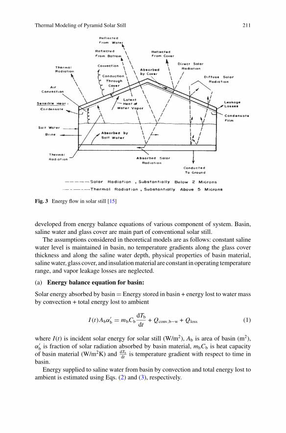
Thermal Modeling of Pyramid Solar Still 211
Fig. 3 Energy flow in solar still [15]
developed from energy balance equations of various component of system. Basin,saline water and glass cover are main part of conventional solar still.
The assumptions considered in theoretical models are as follows: constant salinewater level is maintained in basin, no temperature gradients along the glass coverthickness and along the saline water depth, physical properties of basin material,salinewater, glass cover, and insulationmaterial are constant in operating temperaturerange, and vapor leakage losses are neglected.
(a) Energy balance equation for basin:
Solar energy absorbed by basin� Energy stored in basin + energy lost to water massby convection + total energy lost to ambient
I (t)Abα′b � mbCb
dTbdt
+ Qconv,b−w + Qloss (1)
where I(t) is incident solar energy for solar still (W/m2), Ab is area of basin (m2),α′b is fraction of solar radiation absorbed by basin material, mbCb is heat capacity
of basin material (W/m2K) and dTbdt is temperature gradient with respect to time in
basin.Energy supplied to saline water from basin by convection and total energy lost to
ambient is estimated using Eqs. (2) and (3), respectively.
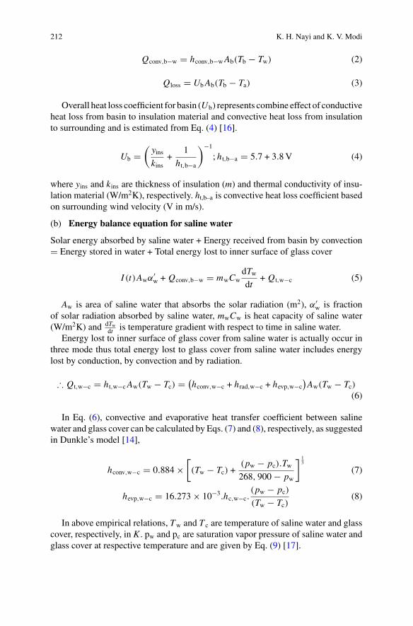
212 K. H. Nayi and K. V. Modi
Qconv,b−w � hconv,b−wAb(Tb − Tw) (2)
Qloss � UbAb(Tb − Ta) (3)
Overall heat loss coefficient for basin (Ub) represents combine effect of conductiveheat loss from basin to insulation material and convective heat loss from insulationto surrounding and is estimated from Eq. (4) [16].
Ub �(yinskins
+1
ht,b−a
)−1
; ht,b−a � 5.7 + 3.8V (4)
where yins and kins are thickness of insulation (m) and thermal conductivity of insu-lation material (W/m2K), respectively. ht,b–a is convective heat loss coefficient basedon surrounding wind velocity (V in m/s).
(b) Energy balance equation for saline water
Solar energy absorbed by saline water + Energy received from basin by convection� Energy stored in water + Total energy lost to inner surface of glass cover
I (t)Awα′w + Qconv,b−w � mwCw
dTwdt
+ Qt,w−c (5)
Aw is area of saline water that absorbs the solar radiation (m2), α′w is fraction
of solar radiation absorbed by saline water, mwCw is heat capacity of saline water(W/m2K) and dTw
dt is temperature gradient with respect to time in saline water.Energy lost to inner surface of glass cover from saline water is actually occur in
three mode thus total energy lost to glass cover from saline water includes energylost by conduction, by convection and by radiation.
∴ Qt,w−c � ht,w−cAw(Tw − Tc) � (hconv,w−c + hrad,w−c + hevp,w−c
)Aw(Tw − Tc)
(6)
In Eq. (6), convective and evaporative heat transfer coefficient between salinewater and glass cover can be calculated by Eqs. (7) and (8), respectively, as suggestedin Dunkle’s model [14],
hconv,w−c � 0.884 ×[(Tw − Tc) +
(pw − pc).Tw268, 900 − pw
] 13
(7)
hevp,w−c � 16.273 × 10−3.hc,w−c.(pw − pc)
(Tw − Tc)(8)
In above empirical relations, Tw and T c are temperature of saline water and glasscover, respectively, in K . pw and pc are saturation vapor pressure of saline water andglass cover at respective temperature and are given by Eq. (9) [17].
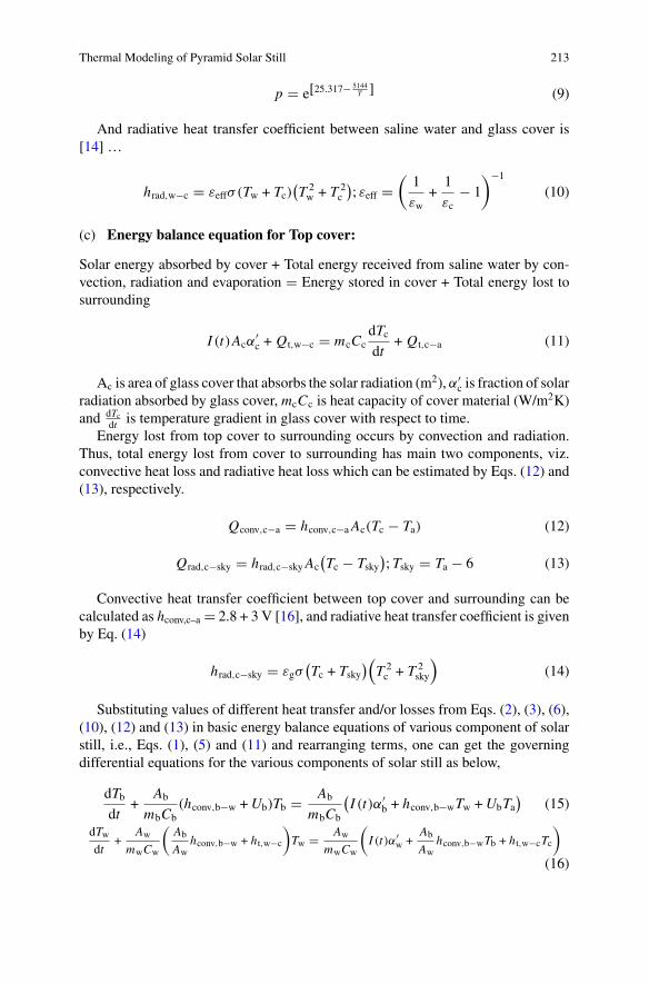
Thermal Modeling of Pyramid Solar Still 213
p � e[25.317−5144T ] (9)
And radiative heat transfer coefficient between saline water and glass cover is[14] …
hrad,w−c � εeffσ(Tw + Tc)(T 2w + T 2
c
); εeff �
(1
εw+
1
εc− 1
)−1
(10)
(c) Energy balance equation for Top cover:
Solar energy absorbed by cover + Total energy received from saline water by con-vection, radiation and evaporation � Energy stored in cover + Total energy lost tosurrounding
I (t)Acα′c + Qt,w−c � mcCc
dTcdt
+ Qt,c−a (11)
Ac is area of glass cover that absorbs the solar radiation (m2), α′c is fraction of solar
radiation absorbed by glass cover, mcCc is heat capacity of cover material (W/m2K)and dTc
dt is temperature gradient in glass cover with respect to time.Energy lost from top cover to surrounding occurs by convection and radiation.
Thus, total energy lost from cover to surrounding has main two components, viz.convective heat loss and radiative heat loss which can be estimated by Eqs. (12) and(13), respectively.
Qconv,c−a � hconv,c−aAc(Tc − Ta) (12)
Qrad,c−sky � hrad,c−skyAc(Tc − Tsky
); Tsky � Ta − 6 (13)
Convective heat transfer coefficient between top cover and surrounding can becalculated as hconv,c–a � 2.8 + 3 V [16], and radiative heat transfer coefficient is givenby Eq. (14)
hrad,c−sky � εgσ(Tc + Tsky
)(T 2c + T 2
sky
)(14)
Substituting values of different heat transfer and/or losses from Eqs. (2), (3), (6),(10), (12) and (13) in basic energy balance equations of various component of solarstill, i.e., Eqs. (1), (5) and (11) and rearranging terms, one can get the governingdifferential equations for the various components of solar still as below,
dTbdt
+Ab
mbCb(hconv,b−w +Ub)Tb � Ab
mbCb
(I (t)α′
b + hconv,b−wTw +UbTa)
(15)
dTwdt
+Aw
mwCw
(Ab
Awhconv,b−w + ht,w−c
)Tw � Aw
mwCw
(I (t)α′
w +Ab
Awhconv,b−wTb + ht,w−cTc
)
(16)
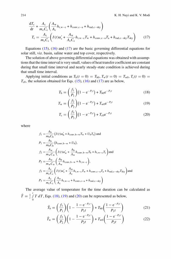
214 K. H. Nayi and K. V. Modi
dTcdt
+Ac
mcCc
(Aw
Acht,w−c + hconv,c−a + hrad,c−sky
)
Tc � Ac
mcCc
(I (t)α′
c +Aw
AcCcht,w−cTw + hconv,c−aTa + hrad,c−skyTsky
)(17)
Equations (15), (16) and (17) are the basic governing differential equations forsolar still, viz. basin, saline water and top cover, respectively.
The solution of above governing differential equations was obtainedwith assump-tions that the time interval is very small, values of heat transfer coefficient are constantduring that small time interval and nearly steady-state condition is achieved duringthat small time interval.
Applying initial conditions as Tb(t � 0) � Tb0, Tw(t � 0) � Tw0, Tc(t � 0) �Tc0, the solution obtained for Eqs. (15), (16) and (17) are as below,
Tb �(
f1P1
)(1 − e−P1t
)+ Tb0e
−P1t (18)
Tw �(
f2P2
)(1 − e−P2t
)+ Tw0e
−P2t (19)
Tc �(
f3P3
)(1 − e−P3t
)+ Tc0e
−P3t (20)
where
f1 � Ab
mbCb
(I (t)α′
b + hconv,b−wTw +UbTa)and
P1 � Ab
mbCb
(hconv,b−w +Ub
),
f2 � Aw
mwCw
(I (t)α′
w +Ab
Awhconv,b−wTb + ht,w−cTc
)and
P2 � Aw
mwCw
(Ab
Awhconv,b−w + ht,w−c
),
f3 � Ac
mcCc
(I (t)α′
c +Aw
Acht,w−cTw + hconv,c−aTa + hrad,c−skyTsky
)and
P3 � Ac
mcCc
(Aw
Acht,w−c + hconv,c−a + hrad,c−sky
)
The average value of temperature for the time duration can be calculated as
T � 1t
t∫0T dT , Eqs. (18), (19) and (20) can be represented as below,
Tb �(
f1P1
)(1 − 1 − e−P1t
P1t
)+ Tb0
(1 − e−P1t
P1t
)(21)
Tw �(
f2P2
)(1 − 1 − e−P2t
P2t
)+ Tw0
(1 − e−P2t
P2t
)(22)
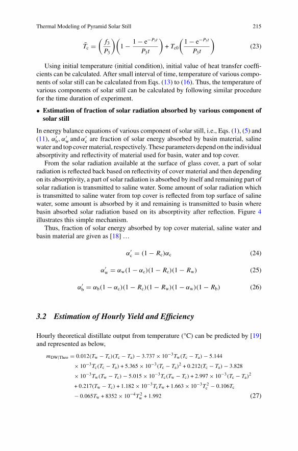
Thermal Modeling of Pyramid Solar Still 215
Tc �(
f3P3
)(1 − 1 − e−P3t
P3t
)+ Tc0
(1 − e−P3t
P3t
)(23)
Using initial temperature (initial condition), initial value of heat transfer coeffi-cients can be calculated. After small interval of time, temperature of various compo-nents of solar still can be calculated from Eqs. (13) to (16). Thus, the temperature ofvarious components of solar still can be calculated by following similar procedurefor the time duration of experiment.
• Estimation of fraction of solar radiation absorbed by various component ofsolar still
In energy balance equations of various component of solar still, i.e., Eqs. (1), (5) and(11), α′
b, α′w andα′
c are fraction of solar energy absorbed by basin material, salinewater and top covermaterial, respectively. These parameters depend on the individualabsorptivity and reflectivity of material used for basin, water and top cover.
From the solar radiation available at the surface of glass cover, a part of solarradiation is reflected back based on reflectivity of cover material and then dependingon its absorptivity, a part of solar radiation is absorbed by itself and remaining part ofsolar radiation is transmitted to saline water. Some amount of solar radiation whichis transmitted to saline water from top cover is reflected from top surface of salinewater, some amount is absorbed by it and remaining is transmitted to basin wherebasin absorbed solar radiation based on its absorptivity after reflection. Figure 4illustrates this simple mechanism.
Thus, fraction of solar energy absorbed by top cover material, saline water andbasin material are given as [18] …
α′c � (1 − Rc)αc (24)
α′w � αw(1 − αc)(1 − Rc)(1 − Rw) (25)
α′b � αb(1 − αc)(1 − Rc)(1 − Rw)(1 − αw)(1 − Rb) (26)
3.2 Estimation of Hourly Yield and Efficiency
Hourly theoretical distillate output from temperature (°C) can be predicted by [19]and represented as below,
mDW|Theo � 0.012(Tw − Tc)(Tc − Ta) − 3.737 × 10⁻³Tw(Tc − Ta) − 5.144
× 10−3Tc(Tc − Ta) + 5.365 × 10⁻³(Tc − Ta)2 + 0.212(Tc − Ta) − 3.828
× 10−3Tw(Tw − Tc) − 5.015 × 10⁻³Tc(Tw − Tc) + 2.997 × 10⁻³(Tc − Ta)2
+ 0.217(Tw − Tc) + 1.182 × 10⁻³TcTw + 1.663 × 10⁻³T 2c − 0.106Tc
− 0.065Tw + 8352 × 10−4T 2w + 1.992 (27)
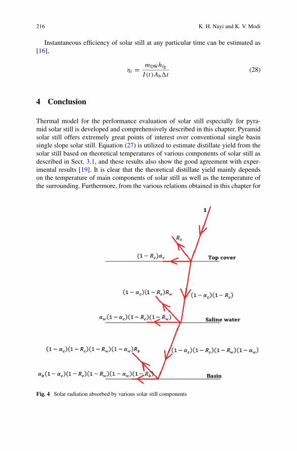
216 K. H. Nayi and K. V. Modi
Instantaneous efficiency of solar still at any particular time can be estimated as[16],
ηi � mDWhfgI (t)Ab�t
(28)
4 Conclusion
Thermal model for the performance evaluation of solar still especially for pyra-mid solar still is developed and comprehensively described in this chapter. Pyramidsolar still offers extremely great points of interest over conventional single basinsingle slope solar still. Equation (27) is utilized to estimate distillate yield from thesolar still based on theoretical temperatures of various components of solar still asdescribed in Sect. 3.1, and these results also show the good agreement with exper-imental results [19]. It is clear that the theoretical distillate yield mainly dependson the temperature of main components of solar still as well as the temperature ofthe surrounding. Furthermore, from the various relations obtained in this chapter for
Fig. 4 Solar radiation absorbed by various solar still components
Thermal Modeling of Pyramid Solar Still 217
temperature estimation, temperature of solar still component (i.e. basin, saline waterand glass cover) has great effect of various climatic parameters like solar radiation,wind speed, surrounding temperature, atmosphere humidity, etc.; various design andmaterial parameters like top cover inclination angle, area and material of absorberplate and condensing cover, salinity of saline water, depth of saline water, thicknessof absorber plate and top cover, thickness and material of insulation, etc. Thus, allparameters mentioned above have a significant effect on the yield of solar still so itis necessary to optimize those all parameters to achive maximum yield. Further, thedaily productivity of pyramid solar still can be improved by providing some addi-tional accessories and add-ons in a simple solar still such as wick materials, storagematerials, nanoparticles, and additional solar collectors and reflectors, etc. Notwith-standing the energy analysis carried out in this chapter, second law efficiency analysisof pyramid solar still need to be developed as it identify areas required for improve-ment in solar still. As pyramid solar still has large advantages over conventional solarstill, pyramid solar still can be thought as an alternative for conventional solar still.
References
1. Jain SK (2011) Population rise and growing water scarcity in India–revised estimates andrequired initiatives. Current Sci 101(3):271–276
2. Al-Hayeka IH, Badran O (2004) The effect of using different designs of solar stills on waterdesalination. Desalination 169:121–127
3. Yadav S, Sudhakar K (2015) Different domestic designs of solar stills: A review. RenewSustainEnergy Rev 47:718–731
4. Sathyamurthy R, Harris Samuel DG, Nagarajan PK, El-Agouz SA (2015) A review of differentsolar still for augmenting fresh water yield. J Environ Sci Technol 8:244–265
5. Kumar PV, Kumar A, Prakash O, Kaviti AK (2015) Solar stills system design: a review. Renewsustain Energy Rev 51:153–181
6. Rufuss DDW, Iniyan S, Suganthi L, Davies PA (2016) Solar stills: a comprehensive review ofdesigns, performance and material advances. Renew Sustain Energy Rev 63:464–496
7. Nayi KH,Modi KV (2018) Pyramid solar still: a comprehensive review. Renew Sustain EnergyRev 81:136–148
8. Sathyamurthy R, Kennady HJ, Nagarajan PK, Ahsan A (2014) Factors affecting the perfor-mance of triangular pyramid solar still. Desalination 344:383–390
9. Yazan Taamneh, Madhar Taamneh (2012) Performance of pyramid-shaped solar still: experi-mental study. Desalination 291:65–68
10. HamdanMA,Musa AM, Jubran BA (1999) Performance of solar still under Jordanian climate.Energy Convers Manag 40:495–503
11. Fath HES, El-Samanoudy M, Fahmy K, Hassabou A (2003) Thermal-economic analysis andcomparison between pyramid shaped and single-slope solar still configurations. Desalination159:69–79
12. Kabeel AE (2009) Performance of solar still with a concave wick evaporation surface. Energy34:1504–1509
13. Mahian O, Kianifar A (2011) Mathematical modelling and experimental study of a solar dis-tillation system. Proc IMechE Part C J Mech Eng Sci 225:1203–1212
14. Dunkle RV (1961) Solar water distillation: the roof type still and amultiple effect diffusion still.In: International development in heat transfer, ASME, proceedings of international transfer PartV. University of Colorado

218 K. H. Nayi and K. V. Modi
15. Garg HP, Dayal M, Furlan G, Sayigh AAM (1987) Physics and technology of solar energy(vol-1): thermal applications, 1st edn. D. Reidel Publishing Company, Holland, p 528
16. Elango C, Gunasekaran N, Sampathkumar K (2015) Thermal models of solar still—a compre-hensive review. Renew Sustain Energy Rev 47:856–919
17. Morad MM, El-Maghawry HA, Wasfy KI (2015) Improving the double slope solar still per-formance by using flat-plate solar collector and cooling glass cover. Desalination 373:1–9
18. Sakthivel M, Shanmugasundaram S (2008) Effect of energy storage medium (black granitegravel) on the performance of a solar still. Int J Energy Res 32:68–82
19. KalidasaMurugavel K, Sivakumar S, RiazAhamed J, ChockalingamKnKSK, SritharK (2010)Single basin double slope solar still with minimum basin depth and energy storing materials.Appl Energy 87:514–523
Integrated PVT Hybrid Active Solar Still(HASS) with an Optimized Numberof Collectors
M. K. Gaur, G. N. Tiwari, Anand Kushwah, Anil Kumar and Gaurav Saxena
Abstract The objective of the chapter was to find the optimum number of collectorsfor PVT hybrid active solar still (HASS). The basin of solar still has been attachedwith number of PVT collectors connected in series. On the basis of energy andexergy analysis, number of collectors has been optimized for water having differentheat capacity. Mathematical relations were derived for determining the temperaturesof water, outer, and inner glass surface. Data of climatic condition in Delhi duringsummer day (May 22, 2008) have been used for the numerical computations. Resultshows that the optimized number of collector rises with the rise in basin water mass.Linear and nonlinear decrement has been observed in exergy efficiency and day-to-day efficiency with the increase in mass of water. Observation based on exergyefficiency shows that the maximum output is obtained at N � 4 for the mass of 50 kgof water. Validation of thermal model is being done by experimental data.
Keywords Optimization · PVT collector · Hybrid solar still · Active · Exergy
1 Introduction
The world population is increasing at a too rapid rate which in turn increases thedemand of human basic needs like food, water, etc. The available fresh water is alsogetting polluted by various means. There are limited fresh water reserves which maynot fulfill the demand in the future. The water scarcity problem is severely affectingvarious dry regions around the globe. Demand of fresh water gets almost double inevery two decades [1].
M. K. Gaur (B) · A. Kushwah · G. SaxenaMechanical Engineering Department, Madhav Institute of Technologyand Science, Gwalior, Indiae-mail: [email protected]
G. N. TiwariCentre of Energy Studies, Indian Institute of Technology Delhi, Delhi, India
A. KumarDepartment of Mechanical Engineering, Delhi Technological University, Delhi 110042, India
© Springer Nature Singapore Pte Ltd. 2019A. Kumar and O. Prakash (eds.), Solar Desalination Technology,Green Energy and Technology, https://doi.org/10.1007/978-981-13-6887-5_10
219
220 M. K. Gaur et al.
India has only 4% of fresh water, feeding 17% of world population. World isgoing to face the biggest challenge of availability of fresh water. By year 2025,about 25% population of the world will face water scarcity and nearly 65% will facewater-stressed situations. By the year 2030, high water stress condition will arisefor 1/2 of the world population [2]. The solar stills are in existence from sixteenthcentury, as it is cheap and easy method of making fresh water. The water purificationsystems operating on solar energy are basically categorized as active and passivesolar stills [3]. Solar still functions on basic principle of evaporation and condensationprocess. The latent heat released during condensation process is utilized for furtherevaporation process in a double or multiple effects solar still. Use of multiple effectsand active mode equipment such as pumps and fans will raise the solar still efficiencybut the total cost of the system also increases. Active components can be driven byPV/T technologies for reducing operating cost and to attain payback after certainduration.
The solar still performance is judged by its efficiency and productivity. The effi-ciency of single-effect still is expressed as the ratio of latent heat of condensation ofwater to the amount of solar energy falling on the solar still. A short time efficiency(typically 15 min) is called as instantaneous efficiency while whole day efficiencyis called as overall efficiency. The per day water output obtained from the solar stillfrom 1 m2 area is termed as its productivity. Basic passive solar still has productiv-ity of about 25 L/m2 day. Thus, minimum of 1 m2 surface is essential to fulfill thedemand of water requirement of individual for meeting their essential needs [4].
The present chapter describes the methodology which may be used for optimiza-tion of the number of collectors to get maximum day-to-day yield from HASS.Exergy analysis, day-to-day yield, and energy efficiency for water mass of varyingheat capacity is being calculated, and the number of collectors for HASS has beenoptimized.
2 General Description and Review
Hybrid Integrated PV/T System means solar still is integrated with PV module.For unit surface area, PV/T collector gives higher electrical and thermal output incomparison with PV module and also it has reduced initial and maintenance costespecially in a regions having extreme weather condition like deserts and coastlineareas.
Recent improvements in PV/THASS have been done byKumar and Tiwari [5] formaking it more efficient. They observed that obtained day-to-day yield is 3.49 timesas obtained in case of passive solar still. In the literature [6, 7], thermal modelingof integrated system of PV/T solar water heater has been carried out. Inside heattransfer coefficient is studied by Kumar and Tiwari [8] for PV/T HASS.
Glass cover was inclined at an angle of 30° with horizontal. DC Pump is providedto circulate the water in active mode. Readings are taken throughout the year on theCSSPSS and HASS in the natural weather situation of India.
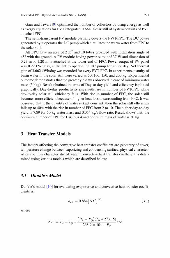
Integrated PVT Hybrid Active Solar Still (HASS) … 221
Gaur and Tiwari [9] optimized the number of collectors by using energy as wellas exergy equations for PVT integrated HASS. Solar still of system consists of PVTattached FPC.
The semi-transparent PV module partially covers the PV/T-FPC. The DC powergenerated by it operates the DC pump which circulates the warm water from FPC tothe solar still.
All FPC have an area of 2 m2 and 10 tubes provided with inclination angle of45° with the ground. A PV module having power output of 37 W and dimension of0.27 m × 1.20 m is attached at the lower end of FPC. Power output of PV panelwas 0.22 kWh/day, sufficient to operate the DC pump for entire day. Net thermalgain of 3.662 kWh/day was recorded for every PVT-FPC. In experiments quantity ofbasin water in the solar still were varied as 50, 100, 150, and 200 kg. Experimentaloutcome demonstrates that the greater yield was observed in case of minimum watermass (50 kg). Result obtained in terms of Day-to-day yield and efficiency is plottedgraphically. Day-to-day productivity rises with rise in number of PVT-FPC whileday-to-day solar still efficiency falls. With rise in number of FPC, the solar stillbecomes more efficient because of higher heat loss to surrounding from FPC. It wasobserved that if the quantity of water is kept constant, then the solar still efficiencyfalls up to 40% with the rise in number of FPC from 2 to 10. The higher day-to-dayyield is 7.89 for 50 kg water mass and 0.054 kg/s flow rate. Result shows that, theoptimum number of FPC for HASS is 4 and optimum mass of water is 50 kg.
3 Heat Transfer Models
The factors affecting the convective heat transfer coefficient are geometry of cover,temperature change between vaporizing and condensing surface, physical character-istics and flow characteristic of water. Convective heat transfer coefficient is deter-mined using various models which are described below:
3.1 Dunkle’s Model
Dunkle’s model [10] for evaluating evaporative and convective heat transfer coeffi-cients is:
hcw � 0.884[�T ′]1/3 (3.1)
where
�T ′ � Tw − Tgi +
(Pw − Pgi
)(Tw + 273.15)
268.9 × 10³ − Pwand
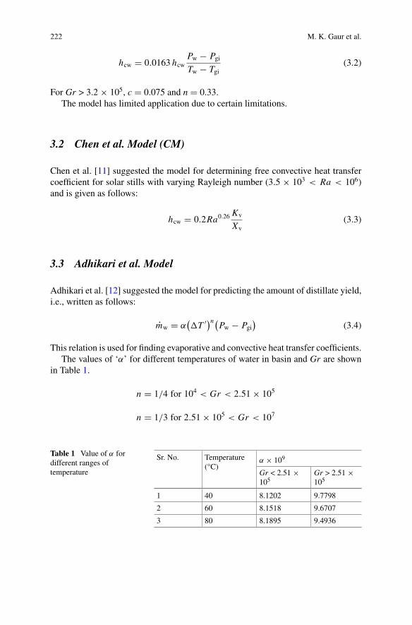
222 M. K. Gaur et al.
hcw � 0.0163 hcwPw − PgiTw − Tgi
(3.2)
For Gr > 3.2 × 10⁵, c � 0.075 and n � 0.33.The model has limited application due to certain limitations.
3.2 Chen et al. Model (CM)
Chen et al. [11] suggested the model for determining free convective heat transfercoefficient for solar stills with varying Rayleigh number (3.5 × 10³ < Ra < 106)and is given as follows:
hcw � 0.2Ra0.26Kv
Xv(3.3)
3.3 Adhikari et al. Model
Adhikari et al. [12] suggested the model for predicting the amount of distillate yield,i.e., written as follows:
mw � α(�T ′)n(Pw − Pgi
)(3.4)
This relation is used for finding evaporative and convective heat transfer coefficients.The values of ‘α’ for different temperatures of water in basin and Gr are shown
in Table 1.
n � 1/4 for 104 < Gr < 2.51 × 10⁵
n � 1/3 for 2.51 × 10⁵ < Gr < 107
Table 1 Value of α fordifferent ranges oftemperature
Sr. No. Temperature(°C)
α × 109
Gr < 2.51 ×10⁵
Gr > 2.51 ×10⁵
1 40 8.1202 9.7798
2 60 8.1518 9.6707
3 80 8.1895 9.4936
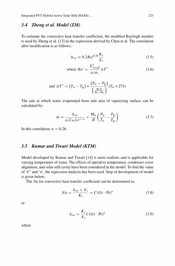
Integrated PVT Hybrid Active Solar Still (HASS) … 223
3.4 Zheng et al. Model (ZM)
To estimate the convective heat transfer coefficient, the modified Rayleigh numberis used by Zheng et al. [13] in the expression derived by Chen et al. The correlationafter modification is as follows:
hcw � 0.2Ra′0.26 Kv
Xv(3.5)
where Ra′ � X3vρvgβ
μvαv�T ′′ (3.6)
and �T ′′ � (Tw − Tgi
)+
(Pw − Pgi
)
(MaPt
Ma−Mw
) (Tw + 273)
The rate at which water evaporated from unit area of vaporizing surface can becalculated by:
m � hcwρvCPvLe1−n
× Mw
R
(PwTw
− PgiTgi
)(3.7)
In this correlation, n � 0.26.
3.5 Kumar and Tiwari Model (KTM)
Model developed by Kumar and Tiwari [14] is more realistic and is applicable forvarying temperature of water. The effects of operative temperature, condenser coveralignment, and solar still cavity have been considered in the model. To find the valueof ‘C’ and ‘n’, the regression analysis has been used. Step of development of modelis given below:
The Nu for convective heat transfer coefficient can be determined as:
Nu � hcw × Xv
Kv� C(Gr · Pr)n (3.8)
or
hcw � Kv
XvC(Gr · Pr)n (3.9)
where
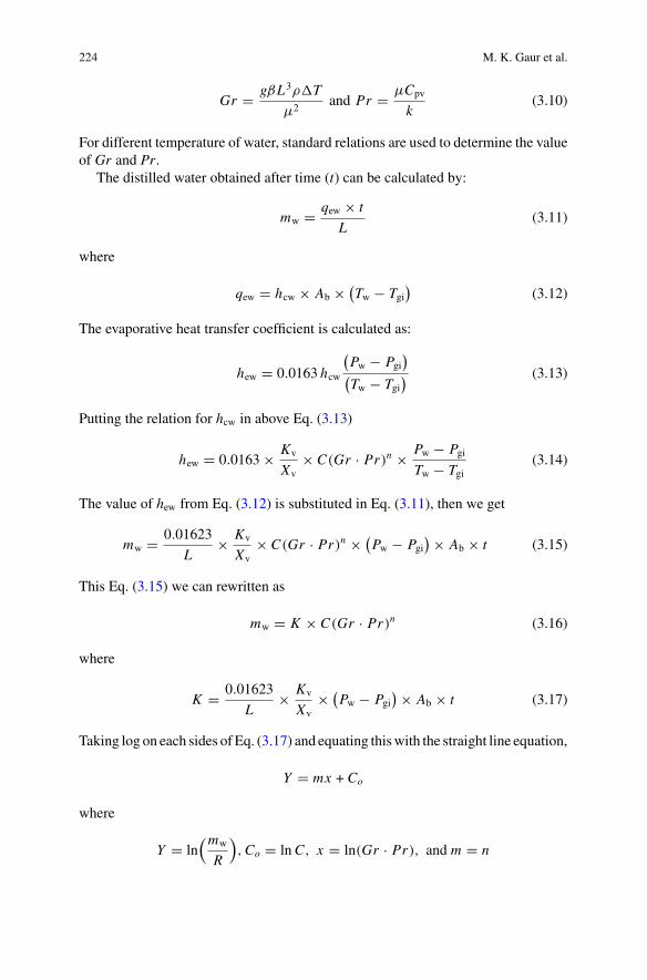
224 M. K. Gaur et al.
Gr � gβL3ρ�T
μ2and Pr � μCpv
k(3.10)
For different temperature of water, standard relations are used to determine the valueof Gr and Pr.
The distilled water obtained after time (t) can be calculated by:
mw � qew × t
L(3.11)
where
qew � hcw × Ab × (Tw − Tgi
)(3.12)
The evaporative heat transfer coefficient is calculated as:
hew � 0.0163 hcw
(Pw − Pgi
)
(Tw − Tgi
) (3.13)
Putting the relation for hcw in above Eq. (3.13)
hew � 0.0163 × Kv
Xv× C(Gr · Pr)n × Pw − Pgi
Tw − Tgi(3.14)
The value of hew from Eq. (3.12) is substituted in Eq. (3.11), then we get
mw � 0.01623
L× Kv
Xv× C(Gr · Pr)n × (
Pw − Pgi) × Ab × t (3.15)
This Eq. (3.15) we can rewritten as
mw � K × C(Gr · Pr)n (3.16)
where
K � 0.01623
L× Kv
Xv× (
Pw − Pgi) × Ab × t (3.17)
Taking log on each sides of Eq. (3.17) and equating thiswith the straight line equation,
Y � mx + Co
where
Y � ln(mw
R
),Co � lnC, x � ln(Gr · Pr), and m � n
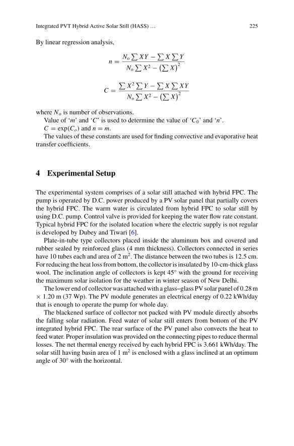
Integrated PVT Hybrid Active Solar Still (HASS) … 225
By linear regression analysis,
n � No∑
XY − ∑X
∑Y
No∑
X2 − (∑X
)2
C �∑
X2 ∑Y − ∑
X∑
XY
No∑
X2 − (∑X
)2
where No is number of observations.Value of ‘m’ and ‘C’ is used to determine the value of ‘C0’ and ‘n’.C � exp(Co) and n � m.The values of these constants are used for finding convective and evaporative heat
transfer coefficients.
4 Experimental Setup
The experimental system comprises of a solar still attached with hybrid FPC. Thepump is operated by D.C. power produced by a PV solar panel that partially coversthe hybrid FPC. The warm water is circulated from hybrid FPC to solar still byusing D.C. pump. Control valve is provided for keeping the water flow rate constant.Typical hybrid FPC for the isolated location where the electric supply is not regularis developed by Dubey and Tiwari [6].
Plate-in-tube type collectors placed inside the aluminum box and covered andrubber sealed by reinforced glass (4 mm thickness). Collectors connected in serieshave 10 tubes each and area of 2 m2. The distance between the two tubes is 12.5 cm.For reducing the heat loss frombottom, the collector is insulated by 10-cm-thick glasswool. The inclination angle of collectors is kept 45° with the ground for receivingthe maximum solar isolation for the weather in winter season of New Delhi.
The lower endof collectorwas attachedwith a glass–glass PVsolar panel of 0.28m× 1.20 m (37 Wp). The PV module generates an electrical energy of 0.22 kWh/daythat is enough to operate the pump for whole day.
The blackened surface of collector not packed with PV module directly absorbsthe falling solar radiation. Feed water of solar still enters from bottom of the PVintegrated hybrid FPC. The rear surface of the PV panel also convects the heat tofeed water. Proper insulation was provided on the connecting pipes to reduce thermallosses. The net thermal energy received by each hybrid FPC is 3.661 kWh/day. Thesolar still having basin area of 1 m2 is enclosed with a glass inclined at an optimumangle of 30° with the horizontal.
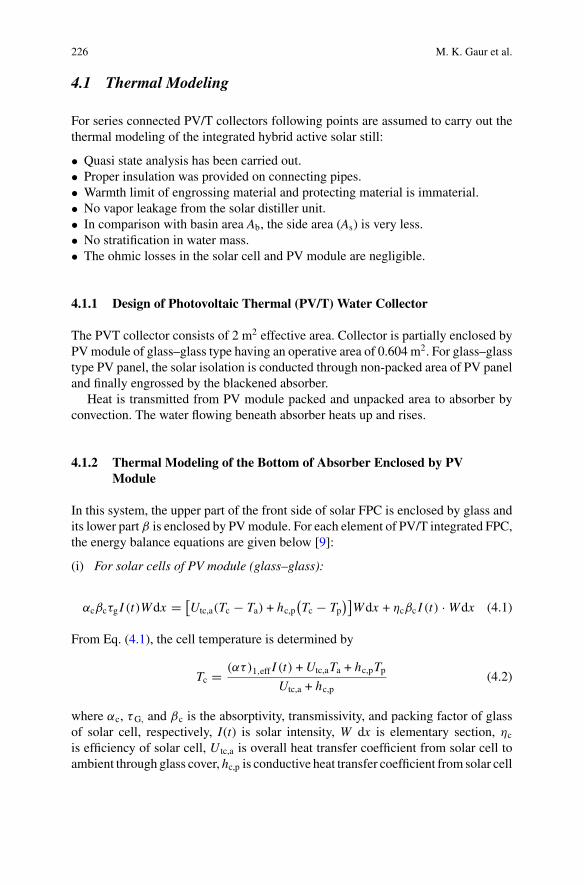
226 M. K. Gaur et al.
4.1 Thermal Modeling
For series connected PV/T collectors following points are assumed to carry out thethermal modeling of the integrated hybrid active solar still:
• Quasi state analysis has been carried out.• Proper insulation was provided on connecting pipes.• Warmth limit of engrossing material and protecting material is immaterial.• No vapor leakage from the solar distiller unit.• In comparison with basin area Ab, the side area (As) is very less.• No stratification in water mass.• The ohmic losses in the solar cell and PV module are negligible.
4.1.1 Design of Photovoltaic Thermal (PV/T) Water Collector
The PVT collector consists of 2 m2 effective area. Collector is partially enclosed byPVmodule of glass–glass type having an operative area of 0.604 m2. For glass–glasstype PV panel, the solar isolation is conducted through non-packed area of PV paneland finally engrossed by the blackened absorber.
Heat is transmitted from PV module packed and unpacked area to absorber byconvection. The water flowing beneath absorber heats up and rises.
4.1.2 Thermal Modeling of the Bottom of Absorber Enclosed by PVModule
In this system, the upper part of the front side of solar FPC is enclosed by glass andits lower part β is enclosed by PVmodule. For each element of PV/T integrated FPC,the energy balance equations are given below [9]:
(i) For solar cells of PV module (glass–glass):
αcβcτg I (t)Wdx � [Utc,a(Tc − Ta) + hc,p
(Tc − Tp
)]Wdx + ηcβc I (t) · Wdx (4.1)
From Eq. (4.1), the cell temperature is determined by
Tc � (ατ)1,eff I (t) +Utc,aTa + hc,pTpUtc,a + hc,p
(4.2)
where αc, τG, and βc is the absorptivity, transmissivity, and packing factor of glassof solar cell, respectively, I(t) is solar intensity, W dx is elementary section, ηc
is efficiency of solar cell, U tc,a is overall heat transfer coefficient from solar cell toambient through glass cover, hc,p is conductive heat transfer coefficient from solar cell
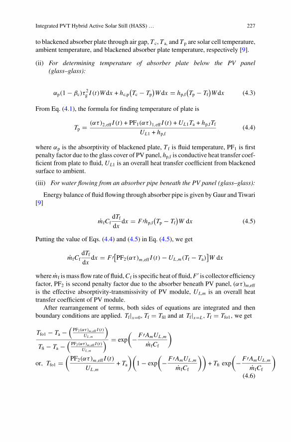
Integrated PVT Hybrid Active Solar Still (HASS) … 227
to blackened absorber plate through air gap, T c, T a, and T p are solar cell temperature,ambient temperature, and blackened absorber plate temperature, respectively [9].
(ii) For determining temperature of absorber plate below the PV panel(glass–glass):
αp(1 − βc)τ2g I (t)Wdx + hc,p
(Tc − Tp
)Wdx � hp,f
(Tp − Tf
)Wdx (4.3)
From Eq. (4.1), the formula for finding temperature of plate is
Tp � (ατ)2,eff I (t) + PF1(ατ)1,eff I (t) +UL1Ta + hp,fTfUL1 + hp,f
(4.4)
where αp is the absorptivity of blackened plate, T f is fluid temperature, PF1 is firstpenalty factor due to the glass cover of PV panel, hp,f is conductive heat transfer coef-ficient from plate to fluid, UL1 is an overall heat transfer coefficient from blackenedsurface to ambient.
(iii) For water flowing from an absorber pipe beneath the PV panel (glass–glass):
Energy balance of fluid flowing through absorber pipe is given byGaur and Tiwari[9]
mfCfdTfdx
dx � F ′hp,f(Tp − Tf
)W dx (4.5)
Putting the value of Eqs. (4.4) and (4.5) in Eq. (4.5), we get
mfCfdTfdx
dx � F ′[PF2(ατ)m,eff I (t) −UL ,m(Tf − Ta)]W dx
where mf ismass flow rate of fluid,Cf is specific heat of fluid,F ′ is collector efficiencyfactor, PF2 is second penalty factor due to the absorber beneath PV panel, (ατ )m,effis the effective absorptivity-transmissivity of PV module, UL,m is an overall heattransfer coefficient of PV module.
After rearrangement of terms, both sides of equations are integrated and thenboundary conditions are applied. Tf|x�0, Tf � Tfil and at Tf|x�L , Tf � Tfo1, we get
Tfo1 − Ta −(PF2(ατ)m,eff I (t)
UL ,m
)
Tfi − Ta −(PF2(ατ)m,eff I (t)
UL ,m
) � exp
(− F ′AmUL ,m
mfCf
)
or, Tfo1 �(PF2(ατ)m,eff I (t)
UL ,m+ Ta
)(1 − exp
(− F ′AmUL ,m
mfCf
))+ Tfi exp
(− F ′AmUL ,m
mfCf
)
(4.6)
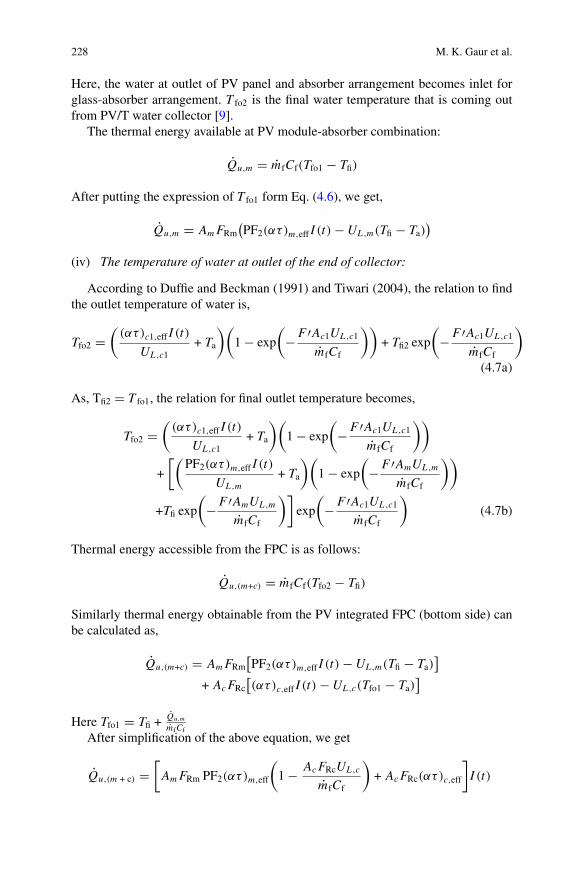
228 M. K. Gaur et al.
Here, the water at outlet of PV panel and absorber arrangement becomes inlet forglass-absorber arrangement. T fo2 is the final water temperature that is coming outfrom PV/T water collector [9].
The thermal energy available at PV module-absorber combination:
Qu,m � mfCf(Tfo1 − Tfi)
After putting the expression of T fo1 form Eq. (4.6), we get,
Qu,m � AmFRm(PF2(ατ)m,eff I (t) −UL ,m(Tfi − Ta)
)
(iv) The temperature of water at outlet of the end of collector:
According to Duffie and Beckman (1991) and Tiwari (2004), the relation to findthe outlet temperature of water is,
Tfo2 �(
(ατ)c1,eff I (t)
UL ,c1+ Ta
)(1 − exp
(− F ′Ac1UL ,c1
mfCf
))+ Tfi2 exp
(− F ′Ac1UL ,c1
mfCf
)
(4.7a)
As, Tfi2 � T fo1, the relation for final outlet temperature becomes,
Tfo2 �(
(ατ)c1,eff I (t)
UL ,c1+ Ta
)(1 − exp
(− F ′Ac1UL ,c1
mfCf
))
+
[(PF2(ατ)m,eff I (t)
UL ,m+ Ta
)(1 − exp
(− F ′AmUL ,m
mfCf
))
+Tfi exp
(− F ′AmUL ,m
mfCf
)]exp
(− F ′Ac1UL ,c1
mfCf
)(4.7b)
Thermal energy accessible from the FPC is as follows:
Qu,(m+c) � mfCf(Tfo2 − Tfi)
Similarly thermal energy obtainable from the PV integrated FPC (bottom side) canbe calculated as,
Qu,(m+c) � AmFRm[PF2(ατ)m,eff I (t) −UL ,m(Tfi − Ta)
]
+ AcFRc[(ατ)c,eff I (t) −UL ,c(Tfo1 − Ta)
]
Here Tfo1 � Tfi +Qu,m
mfCf
After simplification of the above equation, we get
Qu,(m + c) �[AmFRm PF2(ατ)m,eff
(1 − AcFRcUL ,c
mfCf
)+ AcFRc(ατ)c,eff
]I (t)
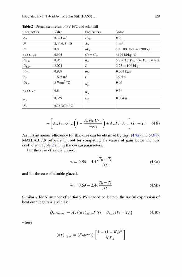
Integrated PVT Hybrid Active Solar Still (HASS) … 229
Table 2 Design parameters of PV FPC and solar still
Parameters Value Parameters Value
Am 0.324 m2 FRc 0.9
N 2, 4, 6, 8, 10 Ab 1 m2
F ′ 0.8 Mw 50, 100, 150 and 200 kg
(ατ )m, eff 0.304 Cf � Cw 4190 kJ/kg °C
FRm 0.95 h2c 5.7 + 3.8 V a,, here V a � 4 m/s
UL,m 2.074 L 2.25 × 10⁵ J/kg
PF2 0.979 mw 0.054 kg/s
Ac 1.675 m2 t 3600 s
UL,c 5 W/m2 °C α′g
0.05
(ατ )c, eff 0.8 α′w
0.34
α′b
0.359 Lg 0.004 m
Kg 0.78 W/m °C
−[AmFRmUL ,m
(1 − AcFRcUL ,c
mfCf
)+ AmFRcUL ,c
](Tfi − Ta) (4.8)
An instantaneous efficiency for this case can be obtained by Eqs. (4.9a) and (4.9b).MATLAB 7.0 software is used for computing the values of gain factor and losscoefficient. Table 2 shows the design parameters.
For the case of single glazed,
ηi � 0.56 − 4.42Tfi − TaI (t)
(4.9a)
and for the case of double glazed,
ηi � 0.59 − 2.46Tfi − TaI (t)
(4.9b)
Similarly for N number of partially PV-shaded collectors, the useful expression ofheat output gain is given as:
Qu,N (m+c) � AN((ατ)eff,N I
′(t) −UL ,N (Tfi − Ta))
(4.10)
where
(ατ)ef f,N � (FR(ατ))1
[1 − (1 − Kk)
N
NKK
]
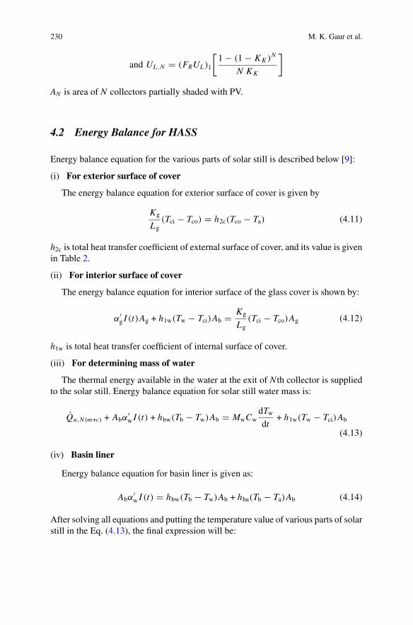
230 M. K. Gaur et al.
and UL ,N � (FRUL)1
[1 − (1 − KK )N
N KK
]
AN is area of N collectors partially shaded with PV.
4.2 Energy Balance for HASS
Energy balance equation for the various parts of solar still is described below [9]:
(i) For exterior surface of cover
The energy balance equation for exterior surface of cover is given by
Kg
Lg(Tci − Tco) � h2c(Tco − Ta) (4.11)
h2c is total heat transfer coefficient of external surface of cover, and its value is givenin Table 2.
(ii) For interior surface of cover
The energy balance equation for interior surface of the glass cover is shown by:
α′g I (t)Ag + h1w(Tw − Tci)Ab � Kg
Lg(Tci − Tco)Ag (4.12)
h1w is total heat transfer coefficient of internal surface of cover.
(iii) For determining mass of water
The thermal energy available in the water at the exit of N th collector is suppliedto the solar still. Energy balance equation for solar still water mass is:
Qu,N (m+c) + Abα′w I (t) + hbw(Tb − Tw)Ab � MwCw
dTwdt
+ h1w(Tw − Tci)Ab
(4.13)
(iv) Basin liner
Energy balance equation for basin liner is given as:
Abα′w I (t) � hbw(Tb − Tw)Ab + hba(Tb − Ta)Ab (4.14)
After solving all equations and putting the temperature value of various parts of solarstill in the Eq. (4.13), the final expression will be:
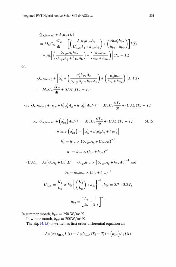
Integrated PVT Hybrid Active Solar Still (HASS) … 231
Qu,N (m+c) + Abα′w I (t)
� MwCwdTwdt
−[(
Abα′gh1wAg
Uc,gaAg + h1wAb
)+
(Abα
′ghbw
hba + hbw
)]I (t)
+ Ab
[(Uc,gaAgh1w
Uc,gaAg + h1wAb
)+
(hbahbw
hba + hbw
)](Tw − Ta)
or,
Qu,N (m+c) +
[α
′w +
(α′gh1wAg
Uc,gaAg + h1wAb
)+
(α′bhbw
hba + hbw
)]Ab I (t)
� MwCwdTwdt
+ (U A)s(Tw − Ta)
or, Qu,N (m+c) +[α
′w + h′
1α′gAg + h1α
′b
]Ab I (t) � MwCw
dTwdt
+ (U A)s(Tw − Ta)
or, Qu,N (m+c) +(α
′eff
)Ab I (t) � MwCw
dTw
dt+ (U A)s(Tw − Ta) (4.15)
where(α
′eff
)�
[α
′w + h′
1α′gAg + h1α
′b
]
h′1 � h1w × (
Uc,gaAg +U1wAb)−1
h1 � hbw × (hba + hbw)−1
(U A)s � Ab[Ut Ag +Ub
],Ut � Uc,gah1w × [
Uc,gaAg + h1wAb]−1
and
Ub � hbahbw × (hba + hbw)−1
Uc,ga � Kg
Lg× h2c
{(Kg
Lg
)+ h2c
}−1
, h2c � 5.7 + 3.8Va
hba �[Lb
kb+
1
2.8
]−1
In summer month, hbw � 250 W/m2 K.In winter month, hbw � 200W/m2 K.The Eq. (4.15) is written as first order differential equation as:
AN (ατ)eff,N I′(t) − ANUL ,N (Tfi − Ta) +
(α
′eff
)Ab I (t)
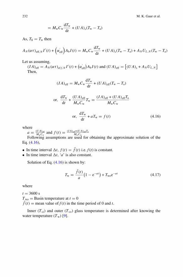
232 M. K. Gaur et al.
� MwCwdTwdt
+ (U A)s(Tw − Ta)
As, Tfi � Tw then
AN (ατ)eff,N I′(t) +
(α
′eff
)Ab I (t) � MwCw
dTwdt
+ (U A)s(Tw − Ta) + ANUL ,N (Tw − Ta)
Let us assuming,(I A)eff � AN (ατ)ef f,N I
′(t) +(α
′eff
)Ab I (t) and (U A)eff � [
(U A)s + ANUL ,N]
Then,
(I A)eff � MwCwdTwdt
+ (U A)eff(Tw − Ta)
or,dTwdt
+(U A)eff
MwCwTw � (I A)eff + (U A)effTa
MwCw
or,dTwdt
+ aTw � f (t) (4.16)
wherea � (U A)eff
MwCwand f (t) � (I A)eff+(U A)effTa
MwCw
Following assumptions are used for obtaining the approximate solution of theEq. (4.16),
• In time interval �t, f (t) � f (t) i.e. f (t) is constant.• In time interval �t, ‘a’ is also constant.
Solution of Eq. (4.16) is shown by:
Tw � f (t)
a
(1 − e−at
)+ Twoe
−at (4.17)
where
t � 3600 sTwo � Basin temperature at t � 0f (t) � mean value of f (t) in the time period of 0 and t.
Inner (T ci) and outer (T co) glass temperature is determined after knowing thewater temperature (Tw) [9].
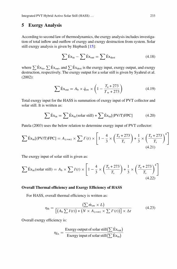
Integrated PVT Hybrid Active Solar Still (HASS) … 233
5 Exergy Analysis
According to second law of thermodynamics, the exergy analysis includes investiga-tion of total inflow and outflow of exergy and exergy destruction from system. Solarstill exergy analysis is given by Hepbasli [15]:
∑Exin −
∑Exout �
∑Exdest (4.18)
where∑
Exin,∑
Exout, and∑
Exdest is the exergy input, exergy output, and exergydestruction, respectively. The exergy output for a solar still is given by Syahrul et al.(2002):
∑Exout � Ab × qew ×
(1 − Ta + 273
Tw + 273
)(4.19)
Total exergy input for the HASS is summation of exergy input of PVT collector andsolar still. It is written as:
∑Exin �
∑Exin(solar still) +
∑Exin[(PV/T)FPC] (4.20)
Patela (2003) uses the below relation to determine exergy input of PVT collector:
∑Exin[(PV/T)FPC] � A(c+m) ×
∑I ′(t) ×
[
1 − 4
3×
(Ta + 273
Ts
)+1
3×
(Ta + 273
Ts
)4]
(4.21)
The exergy input of solar still is given as:
∑Exin(solar still) � Ab ×
∑I (t) ×
[
1 − 4
3×
(Ta + 273
Ts
)+1
3×
(Ta + 273
Ts
)4]
(4.22)
Overall Thermal efficiency and Exergy Efficiency of HASS
For HASS, overall thermal efficiency is written as:
ηth �(∑
mew × L)
[(Ab
∑I (t)
)+
(N × A(c+m) × ∑
I ′(t))] × �t
(4.23)
Overall exergy efficiency is:
ηEx � Exergy output of solar still(∑
Exout)
Exergy input of solar still(∑
Exin)
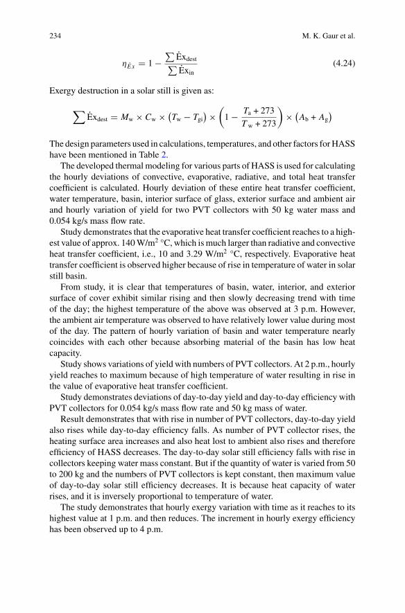
234 M. K. Gaur et al.
ηE x � 1 −∑
Exdest∑Exin
(4.24)
Exergy destruction in a solar still is given as:
∑Exdest � Mw × Cw × (
Tw − Tgi) ×
(1 − Ta + 273
Tw + 273
)× (
Ab + Ag)
The design parameters used in calculations, temperatures, and other factors forHASShave been mentioned in Table 2.
The developed thermal modeling for various parts of HASS is used for calculatingthe hourly deviations of convective, evaporative, radiative, and total heat transfercoefficient is calculated. Hourly deviation of these entire heat transfer coefficient,water temperature, basin, interior surface of glass, exterior surface and ambient airand hourly variation of yield for two PVT collectors with 50 kg water mass and0.054 kg/s mass flow rate.
Study demonstrates that the evaporative heat transfer coefficient reaches to a high-est value of approx. 140W/m2 °C, which is much larger than radiative and convectiveheat transfer coefficient, i.e., 10 and 3.29 W/m2 °C, respectively. Evaporative heattransfer coefficient is observed higher because of rise in temperature of water in solarstill basin.
From study, it is clear that temperatures of basin, water, interior, and exteriorsurface of cover exhibit similar rising and then slowly decreasing trend with timeof the day; the highest temperature of the above was observed at 3 p.m. However,the ambient air temperature was observed to have relatively lower value during mostof the day. The pattern of hourly variation of basin and water temperature nearlycoincides with each other because absorbing material of the basin has low heatcapacity.
Study shows variations of yield with numbers of PVT collectors. At 2 p.m., hourlyyield reaches to maximum because of high temperature of water resulting in rise inthe value of evaporative heat transfer coefficient.
Study demonstrates deviations of day-to-day yield and day-to-day efficiency withPVT collectors for 0.054 kg/s mass flow rate and 50 kg mass of water.
Result demonstrates that with rise in number of PVT collectors, day-to-day yieldalso rises while day-to-day efficiency falls. As number of PVT collector rises, theheating surface area increases and also heat lost to ambient also rises and thereforeefficiency of HASS decreases. The day-to-day solar still efficiency falls with rise incollectors keeping water mass constant. But if the quantity of water is varied from 50to 200 kg and the numbers of PVT collectors is kept constant, then maximum valueof day-to-day solar still efficiency decreases. It is because heat capacity of waterrises, and it is inversely proportional to temperature of water.
The study demonstrates that hourly exergy variation with time as it reaches to itshighest value at 1 p.m. and then reduces. The increment in hourly exergy efficiencyhas been observed up to 4 p.m.
Integrated PVT Hybrid Active Solar Still (HASS) … 235
Study demonstrates the variations in day-to-day exergy and day-to-day exergyefficiency with numbers of collectors for fixed mass and water mass flow. With therise in number of collectors, the day-to-day exergy rises because of increased watertemperature. Maximum day-to-day exergy efficiency is observed for two collectors,and it falls with rise in the number of collectors.
At high temperature, the heat lost to surrounding is more in comparison with gainin useful energy.
Study demonstrates the day-to-day exergy efficiency variation with number ofcollectors for different water mass. As the water mass rises from 50 to 200 kg, theday-to-day exergy efficiency decreases for two or more numbers of PVT collectors.
Two number of collectors is the optimum value for 50 kg water mass for givenHASS. Similarlywe can obtain the value of optimumnumber of collectors for variousmass values of solar still.
6 Conclusion
On the basis of experimentation on a solar still attached with FPC and photovoltaicmodule with 0.054 kg/s mass flow rate and different water mass and other solar stillparameters (Table 2), these observations have been made:
i. Evaporative heat transfer coefficient is observed higher in comparison with con-vective and radiative heat transfer coefficients.
ii. The day-to-day yield obtained during experimentation (7.9 kg) is greater thanday-to-day yield of passive solar still obtained by different investigators.
iii. Based on day-to-day exergy efficiency, it has been noticed that with rise in massof basin water, optimum number of collectors also increases.
References
1. Reif JH, Alhalabi W (2015) Solar-thermal powered desalination: its significant challenges andpotential. Renew Sustain Energy Rev 48:152–165
2. http://www.fewresources.org/water-scarcity-issues-were-running-out-ofwater.html. Accessed07 May 18
3. Raju VR, Narayana RL (2016) Effect of flat plate collectors in series on performance of activesolar still for Indian coastal climatic condition. J King Saud Univ Eng Sci 30(1):78–85
4. Kalidasa Murugavel K, Chockalingam KKSK, Srithar K (2008) Progresses in improving theeffectiveness of the single basin passive solar still. Desalination 220:677–686
5. Kumar S, Tiwari A (2008) An experimental study of hybrid photovoltaic thermal (PV/T) activesolar still. Int J Energy Res 32:847–858
6. Dubey S, Tiwari GN (2008) Thermal modeling of a combined system of photovoltaic thermal(PV/T) solar water heater. Sol Energy 82:602–612
7. Tiwari, Dubey S, SandhuGS, SodhaMS, Anwar SI (2009) Exergy analysis of integrated photo-voltaic thermal solar water heater under constant flow rate and constant collection temperaturemodes. Appl Energy 86:2592–2597

236 M. K. Gaur et al.
8. Kumar S, Tiwari GN (2009) Estimation of internal heat transfer coefficients of a hybrid (PV/Tactive solar still. Sol Energy 83(9):1656–1667
9. Gaur MK, Tiwari GN (2010) Optimization of number of collectors for integrated PV/T hybridactive solar still. Appl Energy 87:1763–1772
10. Dunkle RV (1961) Solar water distillation; the roof type solar still and a multi effect diffusionstill. In: International developments in heat transfer, part V. ASME, University of Colorado, p895
11. Chen Z, Ge X, Sun X, Bar L,Miao YX (1984) Natural convection heat transfer across air layersat various angles of inclination. Engineering thermo physics, pp 211–220 (Special issue for theUSCHINA, bination heat transfer workshop)
12. Adhikari RS, Kumar A, Kumar A (1990) Estimation of mass transfer rates in solar stills. Int JEnergy Res 14:737–744
13. Zheng H, Zhang X, Zhang J, Wu Y (2002) A group of improved heat and mass transfercorrelations in solar stills. Energy Convers Manag 43:2469–2478
14. Kumar S, Tiwari GN (1996) Estimation of convective mass transfer in solar distillation system.Sol Energy 57:459–464
15. Hepbasli A (2008) A key review on exegetic analysis and assessment of renewable energyresources for a sustainable future. Renew Sustain Energ Rev 12:593–661
Analysis of Solar Stills by Using SolarFraction
Rajesh Tripathi
Abstract Thermal modeling of solar stills is based on energy balance equation foreach component of the solar still, viz. condensing cover, water mass, and basin liner.These energy balance equations are dependent on the climatic conditions and designparameters of the solar still. The climatic conditions and design parameters used inthe chapter include the following:
(i) Absorptivity and reflectivity of condensing cover, water surface, and basin ofsolar still
(ii) Transmissivity of condensing cover and water surface(iii) Heat capacity of condensing cover and water mass(iv) Thickness of condensing cover(v) Basin water depth(vi) Solar intensity(vii) Water, basin, condensing cover, and ambient temperatures(viii) Wind velocity(ix) Time.
In the present chapter, a thermal model of passive and active solar stills has beendescribed in detail by calculating solar fraction inside the solar still. The thermalmodeling has been done by using the latitude, longitude of the location of experiment,that is, Delhi. Solar fraction is calculated for given solar azimuth and altitude angleusing AutoCAD software.
Keywords Solar fraction · Solar still · Thermal modeling
NomenclatureAc Area of collector (m2)AE Area of east wall (m2)
R. Tripathi (B)Department of Physics, Galgotias College of Engineering and Technology,Greater Noida 201306, Indiae-mail: [email protected]
© Springer Nature Singapore Pte Ltd. 2019A. Kumar and O. Prakash (eds.), Solar Desalination Technology,Green Energy and Technology, https://doi.org/10.1007/978-981-13-6887-5_11
237
238 R. Tripathi
Ah Area of water directly receiving rays (m2)AN Area of north wall (m2)AN′ Area of projection of north wall (m2)AW Area of west wall (m2)AS Area of south wall (m2)Awater Area of water surface (m2)Cw Specific heat of water in solar still (J/kg °C)Fb Solar fraction for the basin of the stillFn Solar fraction for the north wall of the stillFR Heat removal factorhb Overall heat transfer coefficient from basin liner to ambient air through
bottom and side insulation (W/m2 °C)h1g Convective heat transfer coefficient from glass cover to ambient (W/m2 °C)h1w Total heat transfer coefficient from water surface to glass cover (W/m2 °C)hw Convective heat transfer coefficient from basin liner to water (W/m2 °C)hcw Convective heat transfer coefficient from water surface to glass (W/m2 °C)hew Evaporative heat transfer coefficient fromwater surface to glass (W/m2 °C)I Solar intensity on the glass cover of the solar still (W/m2)Ic Solar intensity on the glass cover of the solar collector panel (W/m2)Ih Solar radiation incident on the horizontal surface of solar still (W/m2)IE Solar radiation incident on the east wall of solar still (W/m2)IW Solar radiation incident on the west wall of solar still (W/m2)IN Solar radiation incident on the north wall of solar still (W/m2)IS Solar radiation incident on the south wall of solar still (W/m2)Ieff Effective solar radiation intensity (W/m2)L Latent heat of vaporization (J/kg)Mw Mass of water in basin (kg)mew Hourly output of still (Kg/m2 h)mew(E) Experimental hourly output of still (Kg/m2 h)mew(T) Theoretical hourly output of still (Kg/m2 h)N Number of observationsQu Rate of useful energy from collector (W)T a Ambient air temperature (°C)T b Basin temperature (°C)T ci Inner temperature of condensing cover (°C)Tw Average water temperature (°C)T g Average glass temperature (°C)UL Overall heat transfer coefficient (W/m2 °C)X i Theoretical or predicted valueY i Experimental value
Analysis of Solar Stills by Using Solar Fraction 239
Greek Symbols
α Absorptivityα′b Solar flux absorbed by the basin liner
α′w Solar flux absorbed by water mass
α′g Solar flux absorbed by glass cover
ρ Reflectivityτ Transmittance
Subscripts
b Basin linerc Collectorg Glass coverw Water
1 Introduction
Using solar energy to obtain potable water from saline/brackish water is known assolar distillation. Different methods have been in existence since the fourth centuryB.C. for getting potable water from saline/brackish water. Delyannis and Delyannis[3] and Talbert et al. [18] overviewed different solar distillation plants in the world.Delyannis [4] and Tiwari et al. [23] reviewed various methods of passive and activesolar distillation along with different models that increased the productivity of stills.Tiwari and Rao [22], Tiwari and Yadav [24] and Tiwari et al. [21] classified solardistillation systems in two main categories; passive and active solar stills as they areshown in Fig. 1. The passive solar still can be further classified as conventional singleslope solar still and conventional double slope solar still. Conventional double slopesolar still is further classified as symmetrical and non-symmetrical double slope solarstills.
The yield of solar stills can be increased by several methods; however, most of thestudies are done using concentrators and flat-plate collectors. Dunkle [5], Cooper,[2], Hirschmann and Roefler [8] and Kumar and Tiwari [11] analyzed heat and masstransfer in solar stills.
Other published works to increase the yield of solar still which is well explainedby Kabeel and Mohamad [10], Tanaka [19], Kabeel and Mohamad [9], Harris andNagarajan [7], Eltawii and Omara [6], Omara [14], Alaudeen et al. [1], Morad et al.[13], Rajamanickam andRajupathy [15], Taamneh [17], Somwanshi and Tiwari [16].
The present chapter deals with thermal modeling of passive and active solar stillsby considering solar fraction inside the solar still in order to increase its yield.
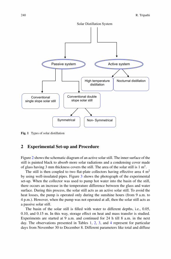
240 R. Tripathi
Solar Distillation System
Non- SymmetricalSymmetrical
Conventional double slope solar still
Nocturnal distillationHigh temperature distillation
Active systemPassive system
Conventional single slope solar still
Fig. 1 Types of solar distillation
2 Experimental Set-up and Procedure
Figure 2 shows the schematic diagram of an active solar still. The inner surface of thestill is painted black to absorb more solar radiations and a condensing cover madeof glass having 3 mm thickness covers the still. The area of the solar still is 1 m2.
The still is then coupled to two flat-plate collectors having effective area 4 m2
by using well-insulated pipes. Figure 3 shows the photograph of the experimentalset-up. When the collector was used to pump hot water into the basin of the still,there occurs an increase in the temperature difference between the glass and watersurface. During this process, the solar still acts as an active solar still. To avoid theheat losses, the pump is operated only during the sunshine hours (from 9 a.m. to4 p.m.). However, when the pump was not operated at all, then the solar still acts asa passive solar still.
The basin of the solar still is filled with water to different depths, i.e., 0.05,0.10, and 0.15 m. In this way, storage effect on heat and mass transfer is studied.Experiments are started at 9 a.m. and continued for 24 h till 8 a.m. in the nextday. The observations presented in Tables 1, 2, 3, and 4 represent for particulardays from November 30 to December 8. Different parameters like total and diffuse
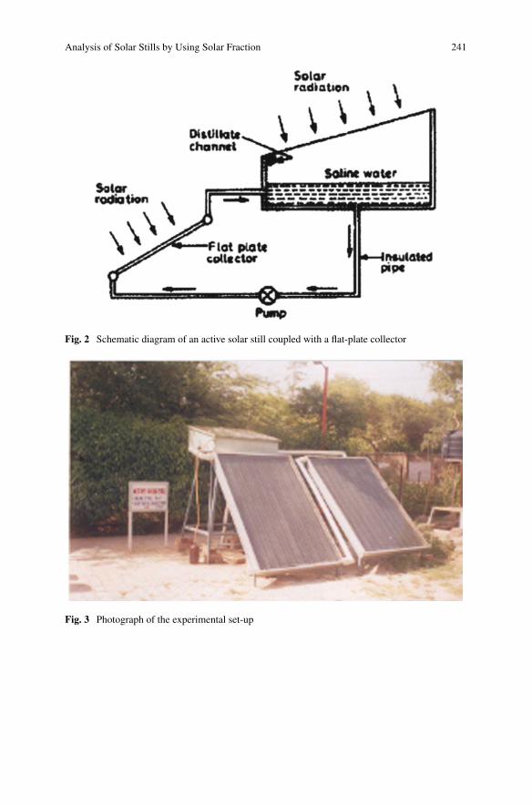
Analysis of Solar Stills by Using Solar Fraction 241
Fig. 2 Schematic diagram of an active solar still coupled with a flat-plate collector
Fig. 3 Photograph of the experimental set-up
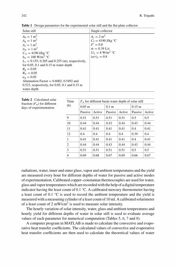
242 R. Tripathi
Table 1 Design parameters for the experimental solar still and the flat-plate collector
Solar still Single collector
Ab = 1 m2
Ag = 1 m2
As = 1 m2
Aw = 1 m2
Cw = 4190 J/kg °Chw = 100 W/m2 °CLv = 0.155, 0.205 and 0.255 (m), respectively,for 0.05, 0.1 and 0.15 m water depthRg = 0.05Rw = 0.05αg = 0.05Attenuation Factor = 0.6002, 0.5492 and0.523, respectively, for 0.05, 0.1 and 0.15 mwater depth
Ac = 2 m2
Cf = 4190 J/kg °CF ′ = 0.8m = 0.39 L/sUL = 8 W/m2 °C(ατ )c = 0.8
Table 2 Calculated solarfraction (Fn) for differentdays of experimentation
Time(h)
Fn for different basin water depth of solar still
0.05 m 0.1 m 0.15 m
Passive Active Passive Active Passive Active
9 0.51 0.51 0.51 0.51 0.5 0.5
10 0.44 0.44 0.43 0.44 0.43 0.44
11 0.41 0.41 0.41 0.41 0.4 0.41
12 0.4 0.4 0.4 0.4 0.39 0.4
1 0.41 0.41 0.41 0.41 0.4 0.41
2 0.44 0.44 0.43 0.44 0.43 0.44
3 0.51 0.51 0.51 0.51 0.5 0.5
4 0.69 0.68 0.67 0.69 0.66 0.67
radiations, water, inner and outer glass, vapor and ambient temperatures and the yieldare measured every hour for different depths of water for passive and active modesof experimentation. Calibrated copper–constantan thermocouples are used for water,glass and vapor temperatureswhich are recordedwith the help of a digital temperatureindicator having the least count of 0.1 °C. A calibrated mercury thermometer havinga least count of 0.1 °C is used to record the ambient temperature and the yield ismeasuredwith ameasuring cylinder of a least count of 10ml.A calibrated solarimeterof a least count of 2 mW/cm2 is used to measure solar intensity.
The hourly variation of solar intensity, water, glass and ambient temperatures andhourly yield for different depths of water in solar still is used to evaluate averagevalues of each parameter for numerical computation (Tables 5, 6, 7 and 8).
A computer program in MATLAB is made to calculate the convective and evapo-rative heat transfer coefficients. The calculated values of convective and evaporativeheat transfer coefficients are then used to calculate the theoretical values of water
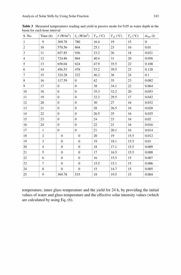
Analysis of Solar Stills by Using Solar Fraction 243
Table 3 Measured temperatures reading and yield in passive mode for 0.05 m water depth in thebasin for each hour interval
S. No. Time (h) I (W/m2) Ic (W/m2) Tw (°C) T ci (°C) T a (°C) mew (l)
1 9 369.78 780 16.4 19 15 0
2 10 570.56 864 25.1 23 16 0.01
3 11 657.85 936 33.2 26 18 0.021
4 12 724.86 864 40.4 31 20 0.056
5 13 658.04 624 47.9 35.5 22 0.108
6 14 456.53 478 53.2 39.5 23 0.128
7 15 324.28 222 46.2 36 24 0.1
8 16 117.59 0 42 35 23 0.082
9 17 0 0 38 34.1 22 0.064
10 18 0 0 35.3 32.2 20 0.053
11 19 0 0 32.3 29.5 17 0.042
12 20 0 0 30 27 16 0.032
13 21 0 0 28 26.5 16 0.028
14 22 0 0 26.5 25 16 0.025
15 23 0 0 24 23 16 0.02
16 24 0 0 22 21 16 0.016
17 1 0 0 21 20.1 16 0.014
18 2 0 0 20 19 15.5 0.012
19 3 0 0 19 18.1 15.5 0.01
20 4 0 0 18 17.1 15.5 0.009
21 5 0 0 17 16.5 15.5 0.008
22 6 0 0 16 15.5 15 0.007
23 7 0 0 15.5 15.1 15 0.006
24 8 0 0 15 14.7 15 0.005
25 9 369.78 535 18 19.5 15 0.004
temperature, inner glass temperature and the yield for 24 h, by providing the initialvalues of water and glass temperature and the effective solar intensity values (whichare calculated by using Eq. (6).
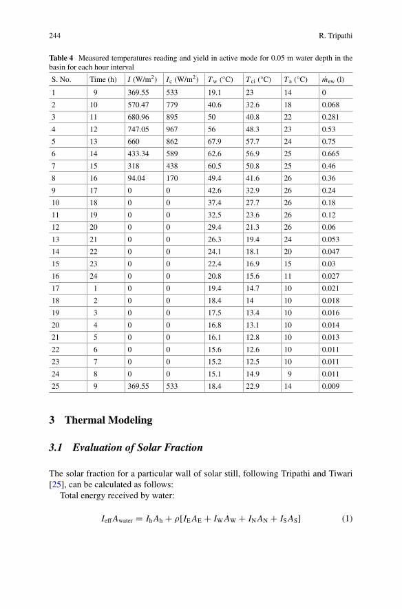
244 R. Tripathi
Table 4 Measured temperatures reading and yield in active mode for 0.05 m water depth in thebasin for each hour interval
S. No. Time (h) I (W/m2) Ic (W/m2) Tw (°C) T ci (°C) T a (°C) mew (l)
1 9 369.55 533 19.1 23 14 0
2 10 570.47 779 40.6 32.6 18 0.068
3 11 680.96 895 50 40.8 22 0.281
4 12 747.05 967 56 48.3 23 0.53
5 13 660 862 67.9 57.7 24 0.75
6 14 433.34 589 62.6 56.9 25 0.665
7 15 318 438 60.5 50.8 25 0.46
8 16 94.04 170 49.4 41.6 26 0.36
9 17 0 0 42.6 32.9 26 0.24
10 18 0 0 37.4 27.7 26 0.18
11 19 0 0 32.5 23.6 26 0.12
12 20 0 0 29.4 21.3 26 0.06
13 21 0 0 26.3 19.4 24 0.053
14 22 0 0 24.1 18.1 20 0.047
15 23 0 0 22.4 16.9 15 0.03
16 24 0 0 20.8 15.6 11 0.027
17 1 0 0 19.4 14.7 10 0.021
18 2 0 0 18.4 14 10 0.018
19 3 0 0 17.5 13.4 10 0.016
20 4 0 0 16.8 13.1 10 0.014
21 5 0 0 16.1 12.8 10 0.013
22 6 0 0 15.6 12.6 10 0.011
23 7 0 0 15.2 12.5 10 0.011
24 8 0 0 15.1 14.9 9 0.011
25 9 369.55 533 18.4 22.9 14 0.009
3 Thermal Modeling
3.1 Evaluation of Solar Fraction
The solar fraction for a particular wall of solar still, following Tripathi and Tiwari[25], can be calculated as follows:
Total energy received by water:
IeffAwater = IhAh + ρ[IEAE + IWAW + INAN + ISAS] (1)
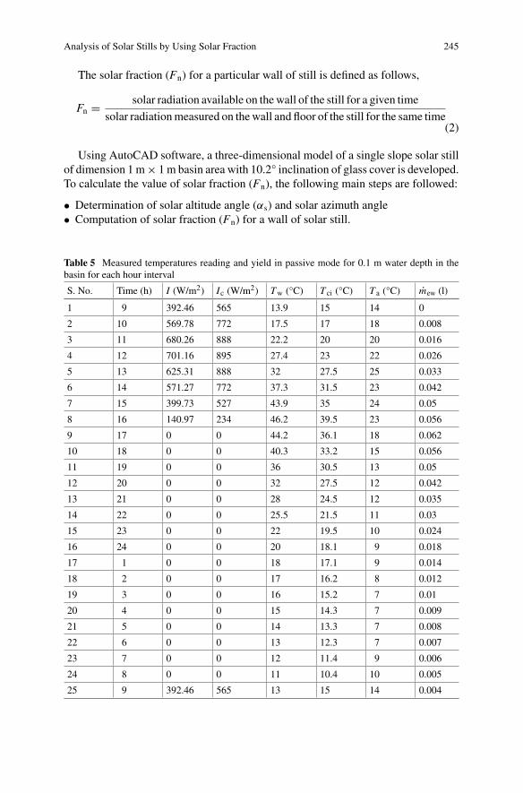
Analysis of Solar Stills by Using Solar Fraction 245
The solar fraction (Fn) for a particular wall of still is defined as follows,
Fn = solar radiation available on thewall of the still for a given time
solar radiationmeasured on thewall and floor of the still for the same time(2)
Using AutoCAD software, a three-dimensional model of a single slope solar stillof dimension 1m× 1m basin area with 10.2° inclination of glass cover is developed.To calculate the value of solar fraction (Fn), the following main steps are followed:
• Determination of solar altitude angle (αs) and solar azimuth angle• Computation of solar fraction (Fn) for a wall of solar still.
Table 5 Measured temperatures reading and yield in passive mode for 0.1 m water depth in thebasin for each hour interval
S. No. Time (h) I (W/m2) Ic (W/m2) Tw (°C) T ci (°C) T a (°C) mew (l)
1 9 392.46 565 13.9 15 14 0
2 10 569.78 772 17.5 17 18 0.008
3 11 680.26 888 22.2 20 20 0.016
4 12 701.16 895 27.4 23 22 0.026
5 13 625.31 888 32 27.5 25 0.033
6 14 571.27 772 37.3 31.5 23 0.042
7 15 399.73 527 43.9 35 24 0.05
8 16 140.97 234 46.2 39.5 23 0.056
9 17 0 0 44.2 36.1 18 0.062
10 18 0 0 40.3 33.2 15 0.056
11 19 0 0 36 30.5 13 0.05
12 20 0 0 32 27.5 12 0.042
13 21 0 0 28 24.5 12 0.035
14 22 0 0 25.5 21.5 11 0.03
15 23 0 0 22 19.5 10 0.024
16 24 0 0 20 18.1 9 0.018
17 1 0 0 18 17.1 9 0.014
18 2 0 0 17 16.2 8 0.012
19 3 0 0 16 15.2 7 0.01
20 4 0 0 15 14.3 7 0.009
21 5 0 0 14 13.3 7 0.008
22 6 0 0 13 12.3 7 0.007
23 7 0 0 12 11.4 9 0.006
24 8 0 0 11 10.4 10 0.005
25 9 392.46 565 13 15 14 0.004
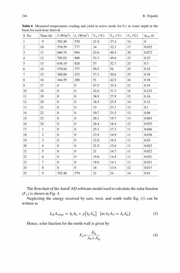
246 R. Tripathi
Table 6 Measured temperatures reading and yield in active mode for 0.1 m water depth in thebasin for each hour interval
S. No. Time (h) I (W/m2) Ic (W/m2) Tw (°C) T ci (°C) T a (°C) mew (l)
1 9 392.48 570 21.8 27.4 14 0
2 10 570.59 777 34 32.3 17 0.032
3 11 680.74 894 42.6 40.4 20 0.072
4 12 702.02 900 52.3 49.6 23 0.25
5 13 636.19 828 57 52.7 25 0.3
6 14 570.84 777 59.5 54 25 0.35
7 15 368.08 532 57.3 50.6 25 0.38
8 16 164.59 288 51 42.5 24 0.36
9 17 0 0 47.5 35.4 21 0.34
10 18 0 0 42.6 31.3 16 0.232
11 19 0 0 38.9 27.9 15 0.16
12 20 0 0 36.5 25.5 14 0.12
13 21 0 0 33 23.1 13 0.1
14 22 0 0 30.7 21.5 12 0.08
15 23 0 0 28.1 19.7 13 0.063
16 24 0 0 26.4 18.4 12 0.053
17 1 0 0 25.1 17.3 11 0.046
18 2 0 0 23.9 16.9 11 0.038
19 3 0 0 22.8 16.5 11 0.03
20 4 0 0 21.9 15.6 11 0.023
21 5 0 0 21 14.7 11 0.022
22 6 0 0 19.8 14.4 11 0.021
23 7 0 0 18.6 14.1 11 0.021
24 8 0 0 18 13.8 12 0.017
25 9 392.48 570 21 24 14 0.01
The flowchart of the AutoCAD software model used to calculate the solar fraction(Fn) is shown in Fig. 4.
Neglecting the energy received by east, west, and south walls Eq. (1) can bewritten as
IeffAwater = IhAh + ρ[IhA
′N
] (as INAN = IhA
′N
)(3)
Hence, solar fraction for the north wall is given by
Fn= A′N
Ah+A′N
(4)
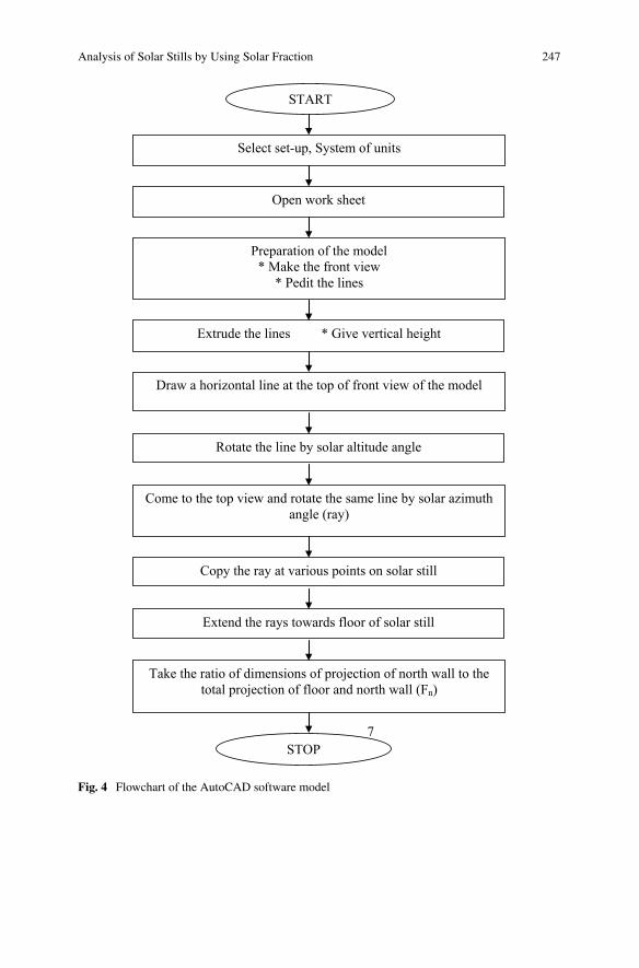
Analysis of Solar Stills by Using Solar Fraction 247
7
START
Select set-up, System of units
Open work sheet
Preparation of the model* Make the front view
* Pedit the lines
Extrude the lines * Give vertical height
Draw a horizontal line at the top of front view of the model
Rotate the line by solar altitude angle
Come to the top view and rotate the same line by solar azimuth angle (ray)
Copy the ray at various points on solar still
Extend the rays towards floor of solar still
Take the ratio of dimensions of projection of north wall to the total projection of floor and north wall (Fn)
STOP
Fig. 4 Flowchart of the AutoCAD software model
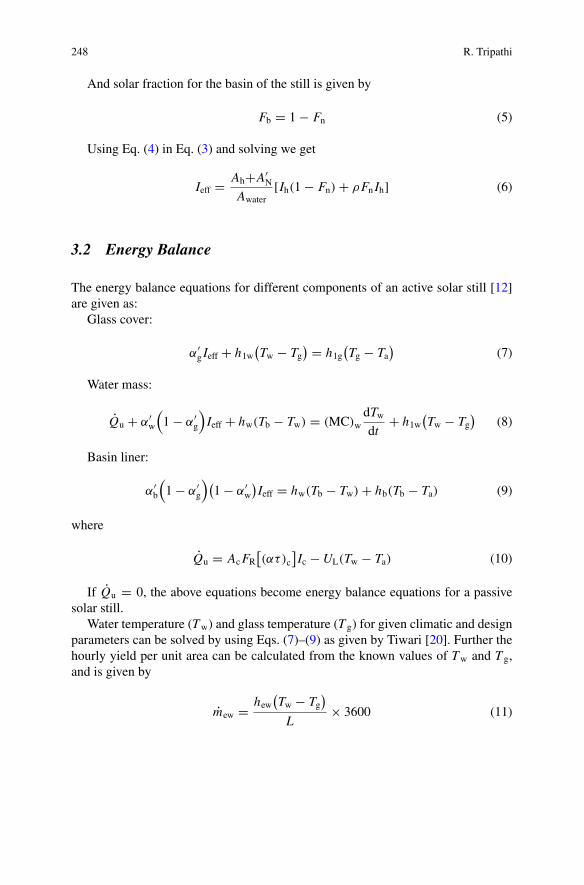
248 R. Tripathi
And solar fraction for the basin of the still is given by
Fb = 1 − Fn (5)
Using Eq. (4) in Eq. (3) and solving we get
Ieff = Ah+A′N
Awater[Ih(1 − Fn) + ρFn Ih] (6)
3.2 Energy Balance
The energy balance equations for different components of an active solar still [12]are given as:
Glass cover:
α′g Ieff + h1w
(Tw − Tg
) = h1g(Tg − Ta
)(7)
Water mass:
Qu + α′w
(1 − α′
g
)Ieff + hw(Tb − Tw) = (MC)w
dTwdt
+ h1w(Tw − Tg
)(8)
Basin liner:
α′b
(1 − α′
g
)(1 − α′
w
)Ieff = hw(Tb − Tw) + hb(Tb − Ta) (9)
where
Qu = AcFR[(ατ)c
]Ic −UL(Tw − Ta) (10)
If Qu = 0, the above equations become energy balance equations for a passivesolar still.
Water temperature (Tw) and glass temperature (T g) for given climatic and designparameters can be solved by using Eqs. (7)–(9) as given by Tiwari [20]. Further thehourly yield per unit area can be calculated from the known values of Tw and T g,and is given by
mew = hew(Tw − Tg
)
L× 3600 (11)
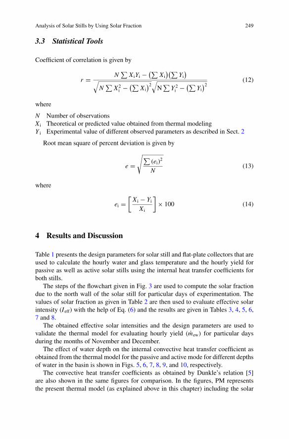
Analysis of Solar Stills by Using Solar Fraction 249
3.3 Statistical Tools
Coefficient of correlation is given by
r = N∑
X iYi −(∑
X i)(∑
Yi)
√N
∑X2i − (∑
X i)2
√N
∑Y 2i − (∑
Yi)2
(12)
where
N Number of observationsX i Theoretical or predicted value obtained from thermal modelingY i Experimental value of different observed parameters as described in Sect. 2
Root mean square of percent deviation is given by
e =√∑
(ei)2
N(13)
where
ei =[X i − Yi
X i
]× 100 (14)
4 Results and Discussion
Table 1 presents the design parameters for solar still and flat-plate collectors that areused to calculate the hourly water and glass temperature and the hourly yield forpassive as well as active solar stills using the internal heat transfer coefficients forboth stills.
The steps of the flowchart given in Fig. 3 are used to compute the solar fractiondue to the north wall of the solar still for particular days of experimentation. Thevalues of solar fraction as given in Table 2 are then used to evaluate effective solarintensity (Ieff) with the help of Eq. (6) and the results are given in Tables 3, 4, 5, 6,7 and 8.
The obtained effective solar intensities and the design parameters are used tovalidate the thermal model for evaluating hourly yield (mew) for particular daysduring the months of November and December.
The effect of water depth on the internal convective heat transfer coefficient asobtained from the thermal model for the passive and active mode for different depthsof water in the basin is shown in Figs. 5, 6, 7, 8, 9, and 10, respectively.
The convective heat transfer coefficients as obtained by Dunkle’s relation [5]are also shown in the same figures for comparison. In the figures, PM representsthe present thermal model (as explained above in this chapter) including the solar
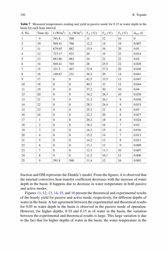
250 R. Tripathi
Table 7 Measured temperatures reading and yield in passive mode for 0.15 m water depth in thebasin for each hour interval
S. No. Time (h) I (W/m2) Ic (W/m2) Tw (°C) T ci (°C) T a (°C) mew (l)
1 9 391.8 560 11 12 16 0
2 10 569.41 766 12.2 14 19 0.007
3 11 679.65 882 15.4 16 20 0.01
4 12 723.17 921 20 19 22 0.014
5 13 681.86 882 24 22 22 0.02
6 14 569.41 765 28 25.5 22 0.028
7 15 321.3 467 32.9 27.5 20 0.036
8 16 140.67 231 36.2 30 14 0.041
9 17 0 0 42.5 33.5 13 0.047
10 18 0 0 40.3 32 12 0.044
11 19 0 0 37.2 30 10 0.04
12 20 0 0 34.2 28.3 10 0.038
13 21 0 0 31.2 26.1 9 0.036
14 22 0 0 28.3 24.4 9 0.033
15 23 0 0 25.2 22 8 0.03
16 24 0 0 22.2 20 8 0.027
17 1 0 0 20.2 18 8 0.024
18 2 0 0 18.2 16 7 0.02
19 3 0 0 16.2 15 6 0.016
20 4 0 0 15.2 14 7 0.013
21 5 0 0 14.2 13 8 0.011
22 6 0 0 13.1 12 9 0.009
23 7 0 0 12.3 11.1 10 0.007
24 8 0 0 11.2 10.1 12 0.006
25 9 391.8 560 11.4 12 16 0.003
fraction and DM represents the Dunkle’s model. From the figures, it is observed thatthe internal convective heat transfer coefficient decreases with the increase of waterdepth in the basin. It happens due to decrease in water temperature in both passiveand active modes.
Figures 11, 12, 13, 14, 15, and 16 present the theoretical and experimental resultsof the hourly yield for passive and active mode, respectively, for different depths ofwater in the basin. A fair agreement between the experimental and theoretical resultsfor 0.05 m water depth in the basin is observed in the passive mode of operation.However, for higher depths, 0.10 and 0.15 m of water in the basin, the variationbetween the experimental and theoretical results is large. This large variation is dueto the fact that for higher depths of water in the basin, the water temperature in the
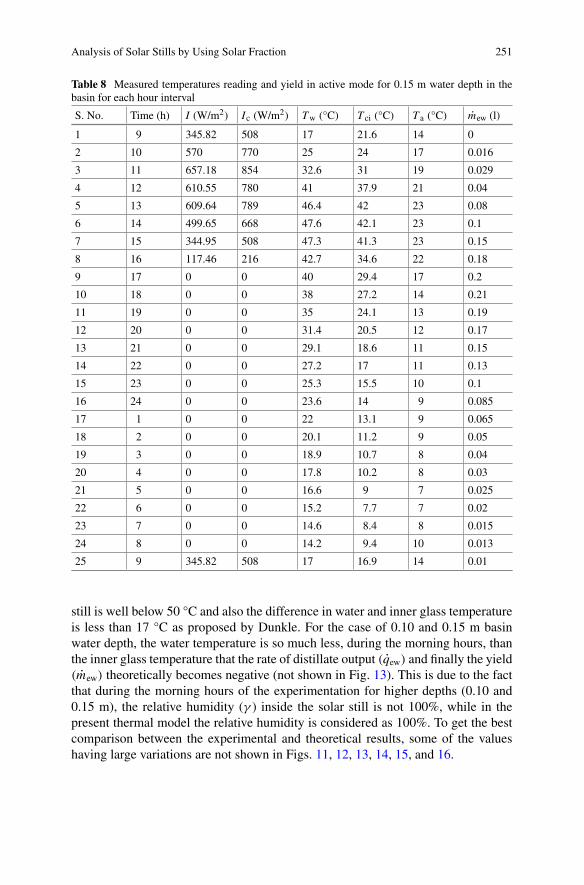
Analysis of Solar Stills by Using Solar Fraction 251
Table 8 Measured temperatures reading and yield in active mode for 0.15 m water depth in thebasin for each hour interval
S. No. Time (h) I (W/m2) Ic (W/m2) Tw (°C) T ci (°C) T a (°C) mew (l)
1 9 345.82 508 17 21.6 14 0
2 10 570 770 25 24 17 0.016
3 11 657.18 854 32.6 31 19 0.029
4 12 610.55 780 41 37.9 21 0.04
5 13 609.64 789 46.4 42 23 0.08
6 14 499.65 668 47.6 42.1 23 0.1
7 15 344.95 508 47.3 41.3 23 0.15
8 16 117.46 216 42.7 34.6 22 0.18
9 17 0 0 40 29.4 17 0.2
10 18 0 0 38 27.2 14 0.21
11 19 0 0 35 24.1 13 0.19
12 20 0 0 31.4 20.5 12 0.17
13 21 0 0 29.1 18.6 11 0.15
14 22 0 0 27.2 17 11 0.13
15 23 0 0 25.3 15.5 10 0.1
16 24 0 0 23.6 14 9 0.085
17 1 0 0 22 13.1 9 0.065
18 2 0 0 20.1 11.2 9 0.05
19 3 0 0 18.9 10.7 8 0.04
20 4 0 0 17.8 10.2 8 0.03
21 5 0 0 16.6 9 7 0.025
22 6 0 0 15.2 7.7 7 0.02
23 7 0 0 14.6 8.4 8 0.015
24 8 0 0 14.2 9.4 10 0.013
25 9 345.82 508 17 16.9 14 0.01
still is well below 50 °C and also the difference in water and inner glass temperatureis less than 17 °C as proposed by Dunkle. For the case of 0.10 and 0.15 m basinwater depth, the water temperature is so much less, during the morning hours, thanthe inner glass temperature that the rate of distillate output (qew) and finally the yield(mew) theoretically becomes negative (not shown in Fig. 13). This is due to the factthat during the morning hours of the experimentation for higher depths (0.10 and0.15 m), the relative humidity (γ ) inside the solar still is not 100%, while in thepresent thermal model the relative humidity is considered as 100%. To get the bestcomparison between the experimental and theoretical results, some of the valueshaving large variations are not shown in Figs. 11, 12, 13, 14, 15, and 16.
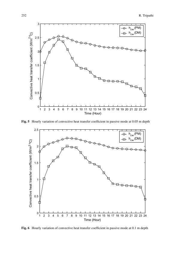
252 R. Tripathi
1 2 3 4 5 6 7 8 9 10 11 12 13 14 15 16 17 18 19 20 21 22 23 240
0.5
1
1.5
2
2.5
3
Time (Hour)
Con
vect
ive
heat
tran
sfer
coe
ffici
ent (
W/m
2o C
)hcw (PM)hcw (DM)
Fig. 5 Hourly variation of convective heat transfer coefficient in passive mode at 0.05 m depth
1 2 3 4 5 6 7 8 9 10 11 12 13 14 15 16 17 18 19 20 21 22 23 240
0.5
1
1.5
2
2.5
Time (Hour)
Con
vect
ive
heat
tran
sfer
coe
ffici
ent (
W/m
2o C
)
hcw (PM)hcw (DM)
Fig. 6 Hourly variation of convective heat transfer coefficient in passive mode at 0.1 m depth
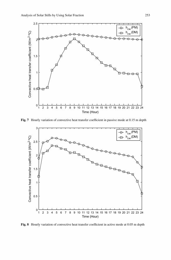
Analysis of Solar Stills by Using Solar Fraction 253
1 2 3 4 5 6 7 8 9 10 11 12 13 14 15 16 17 18 19 20 21 22 23 240
0.5
1
1.5
2
2.5
Time (Hour)
Con
vect
ive
heat
tran
sfer
coe
ffici
ent (
W/m
2o C
)hcw (PM)hcw (DM)
Fig. 7 Hourly variation of convective heat transfer coefficient in passive mode at 0.15 m depth
1 2 3 4 5 6 7 8 9 10 11 12 13 14 15 16 17 18 19 20 21 22 23 240
0.5
1
1.5
2
2.5
3
Time (Hour)
Con
vect
ive
heat
tran
sfer
coe
ffici
ent (
W/m
2o C
)
hcw (PM)hcw (DM)
Fig. 8 Hourly variation of convective heat transfer coefficient in active mode at 0.05 m depth
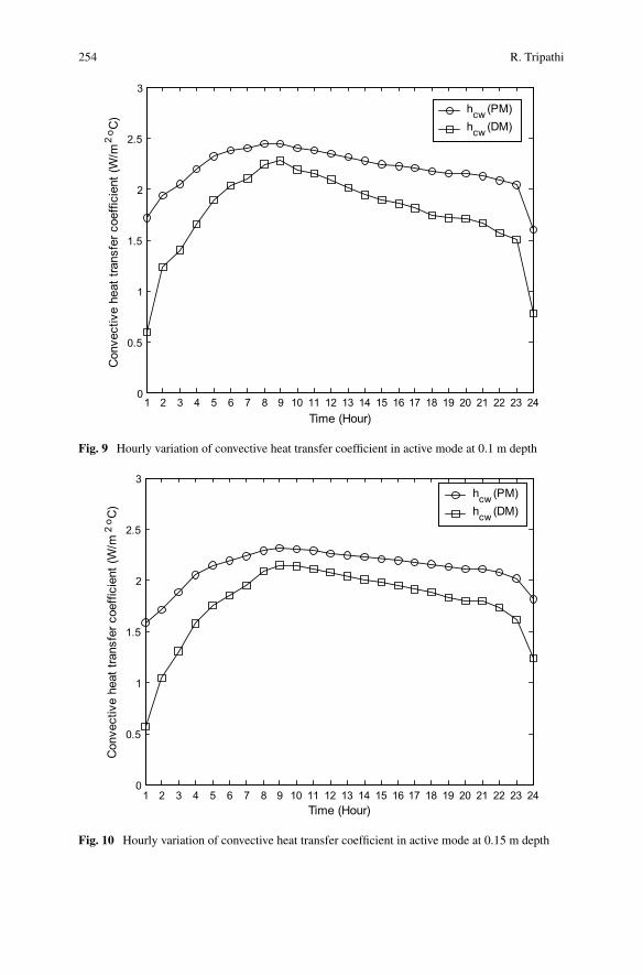
254 R. Tripathi
1 2 3 4 5 6 7 8 9 10 11 12 13 14 15 16 17 18 19 20 21 22 23 240
0.5
1
1.5
2
2.5
3
Time (Hour)
Con
vect
ive
heat
tran
sfer
coe
ffici
ent (
W/m
2o C
)hcw (PM)hcw (DM)
Fig. 9 Hourly variation of convective heat transfer coefficient in active mode at 0.1 m depth
1 2 3 4 5 6 7 8 9 10 11 12 13 14 15 16 17 18 19 20 21 22 23 240
0.5
1
1.5
2
2.5
3
Time (Hour)
Con
vect
ive
heat
tran
sfer
coe
ffici
ent (
W/m
2o C
)
hcw (PM)hcw (DM)
Fig. 10 Hourly variation of convective heat transfer coefficient in active mode at 0.15 m depth
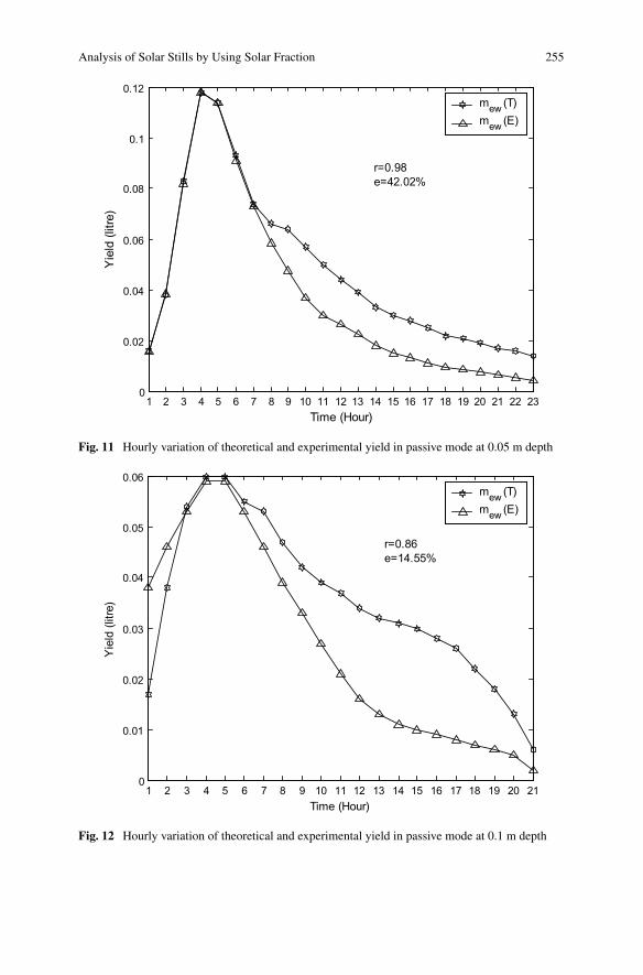
Analysis of Solar Stills by Using Solar Fraction 255
1 2 3 4 5 6 7 8 9 10 11 12 13 14 15 16 17 18 19 20 21 22 230
0.02
0.04
0.06
0.08
0.1
0.12
Time (Hour)
Yie
ld (l
itre)
mew (T)mew (E)
r=0.98e=42.02%
Fig. 11 Hourly variation of theoretical and experimental yield in passive mode at 0.05 m depth
1 2 3 4 5 6 7 8 9 10 11 12 13 14 15 16 17 18 19 20 210
0.01
0.02
0.03
0.04
0.05
0.06
Time (Hour)
Yie
ld (l
itre)
mew (T)mew (E)
r=0.86e=14.55%
Fig. 12 Hourly variation of theoretical and experimental yield in passive mode at 0.1 m depth
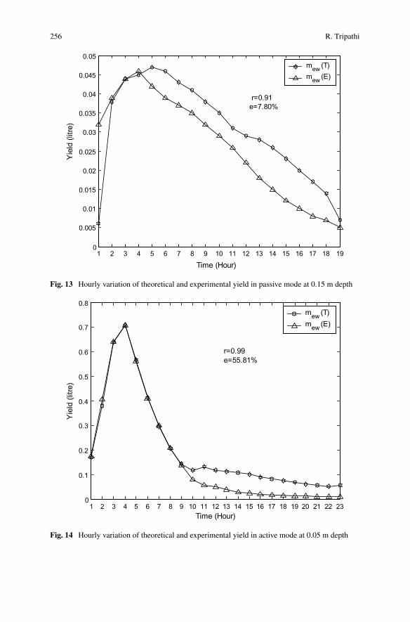
256 R. Tripathi
1 2 3 4 5 6 7 8 9 10 11 12 13 14 15 16 17 18 190
0.005
0.01
0.015
0.02
0.025
0.03
0.035
0.04
0.045
0.05
Time (Hour)
Yie
ld (l
itre)
mew (T)mew (E)
r=0.91e=7.80%
Fig. 13 Hourly variation of theoretical and experimental yield in passive mode at 0.15 m depth
1 2 3 4 5 6 7 8 9 10 11 12 13 14 15 16 17 18 19 20 21 22 230
0.1
0.2
0.3
0.4
0.5
0.6
0.7
0.8
Time (Hour)
Yie
ld (l
itre)
mew (T)mew (E)
r=0.99 e=55.81%
Fig. 14 Hourly variation of theoretical and experimental yield in active mode at 0.05 m depth
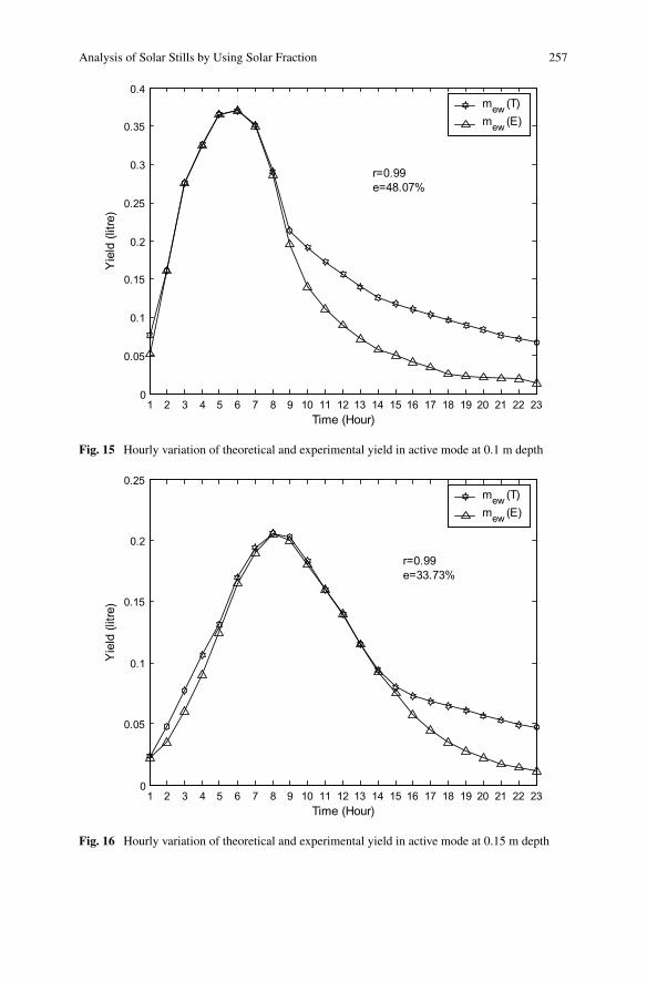
Analysis of Solar Stills by Using Solar Fraction 257
1 2 3 4 5 6 7 8 9 10 11 12 13 14 15 16 17 18 19 20 21 22 230
0.05
0.1
0.15
0.2
0.25
0.3
0.35
0.4
Time (Hour)
Yie
ld (l
itre)
mew (T)mew (E)
r=0.99e=48.07%
Fig. 15 Hourly variation of theoretical and experimental yield in active mode at 0.1 m depth
1 2 3 4 5 6 7 8 9 10 11 12 13 14 15 16 17 18 19 20 21 22 230
0.05
0.1
0.15
0.2
0.25
Time (Hour)
Yie
ld (l
itre)
mew (T)mew (E)
r=0.99e=33.73%
Fig. 16 Hourly variation of theoretical and experimental yield in active mode at 0.15 m depth
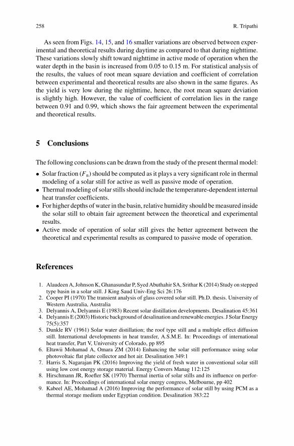
258 R. Tripathi
As seen from Figs. 14, 15, and 16 smaller variations are observed between exper-imental and theoretical results during daytime as compared to that during nighttime.These variations slowly shift toward nighttime in active mode of operation when thewater depth in the basin is increased from 0.05 to 0.15 m. For statistical analysis ofthe results, the values of root mean square deviation and coefficient of correlationbetween experimental and theoretical results are also shown in the same figures. Asthe yield is very low during the nighttime, hence, the root mean square deviationis slightly high. However, the value of coefficient of correlation lies in the rangebetween 0.91 and 0.99, which shows the fair agreement between the experimentaland theoretical results.
5 Conclusions
The following conclusions can be drawn from the study of the present thermalmodel:
• Solar fraction (Fn) should be computed as it plays a very significant role in thermalmodeling of a solar still for active as well as passive mode of operation.
• Thermalmodeling of solar stills should include the temperature-dependent internalheat transfer coefficients.
• For higher depths ofwater in the basin, relative humidity should bemeasured insidethe solar still to obtain fair agreement between the theoretical and experimentalresults.
• Active mode of operation of solar still gives the better agreement between thetheoretical and experimental results as compared to passive mode of operation.
References
1. AlaudeenA, JohnsonK,Ghanasundar P, SyedAbuthahir SA, SritharK (2014) Study on steppedtype basin in a solar still. J King Saud Univ-Eng Sci 26:176
2. Cooper PI (1970) The transient analysis of glass covered solar still. Ph.D. thesis. University ofWestern Australia, Australia
3. Delyannis A, Delyannis E (1983) Recent solar distillation developments. Desalination 45:3614. Delyannis E (2003)Historic background of desalination and renewable energies. J Solar Energy
75(5):3575. Dunkle RV (1961) Solar water distillation; the roof type still and a multiple effect diffusion
still. International developments in heat transfer, A.S.M.E. In: Proceedings of internationalheat transfer, Part V, University of Colorado, pp 895
6. Eltawii Mohamad A, Omara ZM (2014) Enhancing the solar still performance using solarphotovoltaic flat plate collector and hot air. Desalination 349:1
7. Harris S, Nagarajan PK (2016) Improving the yield of fresh water in conventional solar stillusing low cost energy storage material. Energy Convers Manag 112:125
8. Hirschmann JR, Roefler SK (1970) Thermal inertia of solar stills and its influence on perfor-mance. In: Proceedings of international solar energy congress, Melbourne, pp 402
9. Kabeel AE, Mohamad A (2016) Improving the performance of solar still by using PCM as athermal storage medium under Egyptian condition. Desalination 383:22
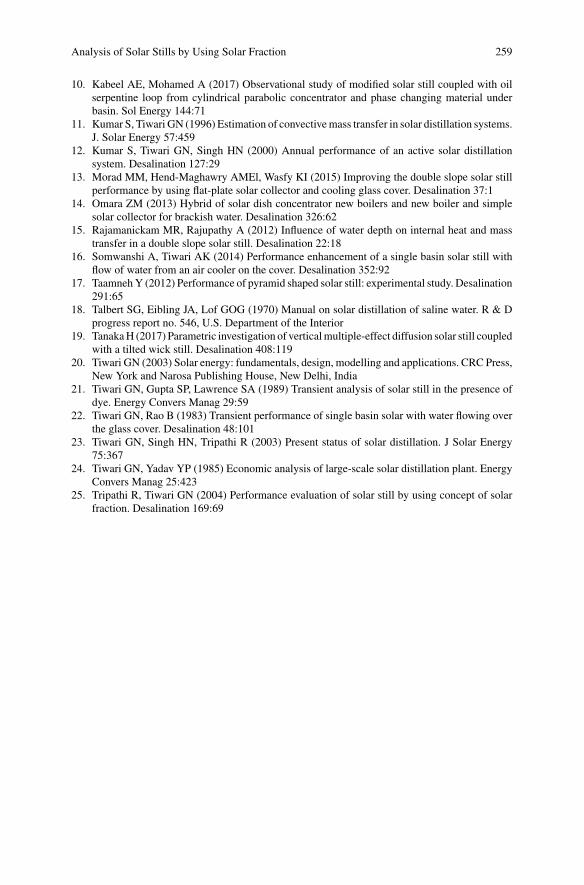
Analysis of Solar Stills by Using Solar Fraction 259
10. Kabeel AE, Mohamed A (2017) Observational study of modified solar still coupled with oilserpentine loop from cylindrical parabolic concentrator and phase changing material underbasin. Sol Energy 144:71
11. Kumar S, Tiwari GN (1996) Estimation of convectivemass transfer in solar distillation systems.J. Solar Energy 57:459
12. Kumar S, Tiwari GN, Singh HN (2000) Annual performance of an active solar distillationsystem. Desalination 127:29
13. Morad MM, Hend-Maghawry AMEl, Wasfy KI (2015) Improving the double slope solar stillperformance by using flat-plate solar collector and cooling glass cover. Desalination 37:1
14. Omara ZM (2013) Hybrid of solar dish concentrator new boilers and new boiler and simplesolar collector for brackish water. Desalination 326:62
15. Rajamanickam MR, Rajupathy A (2012) Influence of water depth on internal heat and masstransfer in a double slope solar still. Desalination 22:18
16. Somwanshi A, Tiwari AK (2014) Performance enhancement of a single basin solar still withflow of water from an air cooler on the cover. Desalination 352:92
17. TaamnehY (2012) Performance of pyramid shaped solar still: experimental study. Desalination291:65
18. Talbert SG, Eibling JA, Lof GOG (1970) Manual on solar distillation of saline water. R & Dprogress report no. 546, U.S. Department of the Interior
19. TanakaH (2017) Parametric investigation of verticalmultiple-effect diffusion solar still coupledwith a tilted wick still. Desalination 408:119
20. Tiwari GN (2003) Solar energy: fundamentals, design, modelling and applications. CRC Press,New York and Narosa Publishing House, New Delhi, India
21. Tiwari GN, Gupta SP, Lawrence SA (1989) Transient analysis of solar still in the presence ofdye. Energy Convers Manag 29:59
22. Tiwari GN, Rao B (1983) Transient performance of single basin solar with water flowing overthe glass cover. Desalination 48:101
23. Tiwari GN, Singh HN, Tripathi R (2003) Present status of solar distillation. J Solar Energy75:367
24. Tiwari GN, Yadav YP (1985) Economic analysis of large-scale solar distillation plant. EnergyConvers Manag 25:423
25. Tripathi R, Tiwari GN (2004) Performance evaluation of solar still by using concept of solarfraction. Desalination 169:69
Exergy Analysis of Active and PassiveSolar Still
Ravi Kant, Om Prakash, Rajesh Tripathi and Anil Kumar
Abstract Over the last fewdecades, theworldwidedemand for freshwater is expand-ing quickly as the supply of freshwater is limited. Solar still (SS) is a profitable sunoriented device that is utilized for changing over the brackish and saline water intoclean water. A number of experiments have been performed on SS to evaluate itsexecution under various climatic and operational conditions. Besides experiments,theoretical investigations have also been helpful in assessing the importance of SS.In this chapter, distinctive methodologies which have been utilized for exergy inves-tigation of solar stills are discussed in detail.
Keywords Desalination · Principle of solar still · Classification of solar still ·Exergy analysis
Nomenclature
As Area of the basin of the still (m2)Cw Solar still water-specific heat (J kg−1 °C−1)Exinput ,Exsun Available energy input in the still (W/m2)Exoutput,Exevap Availability output in the still (W/m2)Exd,b Availability loss in the from basin (W/m2)
R. KantDepartment of Mechanical Engineering, Radharaman Engineering College,Bhopal 462046, India
O. PrakashDepartment of Mechanical Engineering, Birla Institute of Technology,Mesra, Ranchi 835215, India
R. TripathiDepartment of Applied Sciences, Galgotias College of Engineering andTechnology, Greater Noida 201306, India
A. Kumar (B)Department of Mechanical Engineering, Delhi Technological University, Delhi 110042, Indiae-mail: [email protected]
© Springer Nature Singapore Pte Ltd. 2019A. Kumar and O. Prakash (eds.), Solar Desalination Technology,Green Energy and Technology, https://doi.org/10.1007/978-981-13-6887-5_12
261
262 R. Kant et al.
Exw Availability used for water heating (W/m2)Exins Loss of availability due to insulation (W/m2)Exc,w−g Availability due towater and the cover of glass in convection (W/m2)Exe,w−g Availability due to water and the cover of glass in evaporation
(W/m2)Exr,w−g Availability due to water and the cover of glass in radiation (W/m2)Exr,g−a Availability due to cover of glass and atmosphere in radiation
(W/m2)Exc,g−a Availability due to cover of glass and atmosphere in convection
(W/m2)Exin Input of available energy in solar still (W)Exevap Output of available energy in solar still (W)Exdest Loss of availability in solar still water (W)Exsun Available energy input from the sun to the still (W)Exwork Availability of the rate of the work for a still (W)hew Heat transfer coefficient (evaporative) for interface between the sur-
faces of the glass and water (W m−2 °C−1)I(t) Total radiation (W m−2)Qew Thermal energy in evaporation of water vapors (W m−2)qc,w−g Heat transfer (convective) fromwater surface to glass cover (W/m2)qr,w−g Heat transfer (radiative) from surface of water to cover of glass
(W/m2)qe,w−g Heat transfer (Evaporative) from water surface to cover of glass
(W/m2)qc,b−w Heat transfer (convective) from basin to surface of water (W/m2)qb Heat transfer (convective) from basin liner (W/m2)qc,w−g Heat transfer (convective) from surface of water to cover of glass
(W/m2)T a Ambient air temperature (°C)T ci Temperature of the inner cover of the condensing material (°C)TS Temperature from the sun (K)Tw Temperature of water (°C)α Absorptivityg Cover of glassη Efficiencyτ Transmissivityw Mass of watert Totalb Basin liner
Exergy Analysis of Active and Passive Solar Still 263
1 Introduction
Saline/salty water can be cleaned utilizing sun powered energy. The utilization ofsun powered energy to create consumable water is a main factor in removing watercontamination while majority of other water decontamination methods utilize con-ventional energy, for example, coal, oil, gas, and so forth.
A solar still is a device utilized for sunlight based cleaning in which freshwater isobtained from saline water. It is a kind of man made structure of certain materials,such as fiber reinforced plastic (FRP), cement, steel with protection. A glass sheet isused to cover the still from where the sun-oriented radiation enters the water surface.A little reflection and maximum transmission occurs at the cover of the glass and atthe surface of water. A noteworthy amount of radiation is consumed by the liner ofthe basin. The exchange of heat is via convection to the saline water. Exchange fromthe water to the cover of the glass happens by three modes: evaporation, convection,and radiation. Vapor goes out of the majority of ingredients and microorganisms viaheat dissemination to the liner of the basin. The vapor then rises and condenses in theinner cover which is at a temperature less than water. Vapor condensation occurs atthe inner condensing cover, and this condensate trickles down toward the trough dueto sloped glass cover [18]. Scientists have attempted to enhance the output of SS byproposing its different outlines, materials, and working criteria for various climatesituations.
Tiwari and Tiwari have proposed that the SS for a single slope yieldsmay fluctuatefrom 0.5 to 1.2 kg/m2/day during winter time and 1.0–2.5 kg/m2/day during summertime for Delhi (India) climatic conditions [29]. Tiwari and Tiwari estimated theeffectiveness of the SS of single slope as 25.8, 19.7, 22.8% at glass cover slants 15°,30°, and 45° separately for the mid-year climatic state of Delhi, India [30]. Maliket al. have demonstrated that the general effectiveness of a normal SS is accomplishedwith minimum amount of mass of water in the basin [18].
There are large varieties of stills which are used to obtain freshwater from salinewater. Based on converting solar energy, generally solar stills are of 3 types—active,passive, and hybrid. Based on the shape, SS is differentiated as single slope anddouble slope. The various designs of SS are classified in Fig. 1.
The performance of SS can be increased by increasing saline water temperatureusing different techniques such as flat plate collector, external reflector [28], andsolar pond [12]. The productivity of solar still can be increased by 16% by usinginclined external reflector [27]. According to Deniz, various parameters influencingthe productivity of solar still are as follows: inclination angle of condensing cover,cooling of condensing cover, gap distance between condensing cover and watersurface, etc. [4].
The term exergy is used first time in 1956 by the Rant [22]. The exergy is thecombination of two Greek words ex (external) and ergos (work). Available energyof a system is the maximum useful amount of work in the process when systemcomes in equilibrium with surroundings [26]. The nature of energy is understoodby exergy examination in light of the thermodynamics second law and includes the
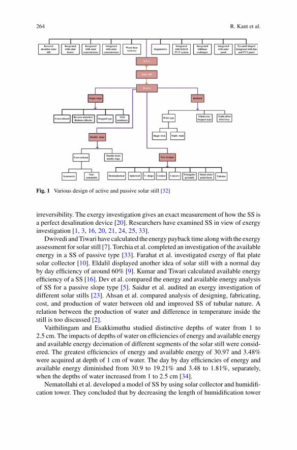
264 R. Kant et al.
Fig. 1 Various design of active and passive solar still [32]
irreversibility. The exergy investigation gives an exact measurement of how the SS isa perfect desalination device [20]. Researchers have examined SS in view of exergyinvestigation [1, 3, 16, 20, 21, 24, 25, 33].
Dwivedi andTiwari have calculated the energy payback time alongwith the exergyassessment for solar still [7]. Torchia et al. completed an investigation of the availableenergy in a SS of passive type [33]. Farahat et al. investigated exergy of flat platesolar collector [10]. Eldalil displayed another idea of solar still with a normal dayby day efficiency of around 60% [9]. Kumar and Tiwari calculated available energyefficiency of a SS [16]. Dev et al. compared the energy and available energy analysisof SS for a passive slope type [5]. Saidur et al. audited an exergy investigation ofdifferent solar stills [23]. Ahsan et al. compared analysis of designing, fabricating,cost, and production of water between old and improved SS of tubular nature. Arelation between the production of water and difference in temperature inside thestill is too discussed [2].
Vaithilingam and Esakkimuthu studied distinctive depths of water from 1 to2.5 cm. The impacts of depths of water on efficiencies of energy and available energyand available energy decimation of different segments of the solar still were consid-ered. The greatest efficiencies of energy and available energy of 30.97 and 3.48%were acquired at depth of 1 cm of water. The day by day efficiencies of energy andavailable energy diminished from 30.9 to 19.21% and 3.48 to 1.81%, separately,when the depths of water increased from 1 to 2.5 cm [34].
Nematollahi et al. developed a model of SS by using solar collector and humidifi-cation tower. They concluded that by decreasing the length of humidification tower
Exergy Analysis of Active and Passive Solar Still 265
and inlet air temperature, the overall efficiency of available energy increases [19].Kwatra did analysis of available energy for describing the thermal behavior of var-ious SS [17]. Nunez et al. analyzed theoretical available energy of steady state andtransient SS. The exergy examinations reveal that a better performance of the ther-moactive is reached when differences in temperature are less after achieving highertemperatures [33].
2 Exergy Analysis of Solar Still
2.1 Passive Solar Still
A number of literatures with exergy investigation of different desalination systemsare found. Various exergy investigations of the solar still have been accounted for inthe writing. Ranjan et al. did examination of energy and available energy for a singleslope solar still. It was seen that the efficiency of energy is in particular incrementsthan the effectiveness of available energy. The momentary rate of available energywas assessed for the parts of detached solar still. It demonstrates that greatest rate onhourly basis of available energy decimations in cover of glass, body of water, linerof the basin reach up to 9.7, 62.5, and 386 W/m2, separately. It has been discoveredthat available energy decimation value in the still segments is particularly reliant onthe amount of sun oriented radiation with time [21].
Shanmugan et al. [25] considered, tentatively, the execution of SS and assessedthe momentary available energy and energy productivity of it. The momentary pro-ductivity of the energy changes during the amid winter from 12.00 to 60.00% andamid summer from 32.00 to 57.00%. The momentary available energy productivityvaries amid winter from 6.00 to 19.00% and amid summer from 7.00 to 18.00%.
Aghaei Zoori et al. [1] displayed hypothetically and tentatively investigation of theefficiencies in energy and available energy of SS. It was observed that the efficiencyof the available energy and energy of the solar still incremented from 3.14 to 10.5%and 44.1 to 83.3%, respectively, when the bay salt water stream rate diminishes from0.2% to 0.065 kg/min.
Kumar and Tiwari [16] thought about the exergy productivity of a slope of singletype SS which is passive in nature and an active one where the SS was combinedwith a photovoltaic unit. They explained that the available energy effectiveness ofthe still of active type was about 5 times high than that of the passive one.
Kianifar et al. [14] investigated an active and a passive pyramid-molded still using2 units to reveal both of available energy and monetary examination. In the detachedSS water depths of 4 cm, the everyday efficiency of available energy observed to be2.43% during winter and 3.06% during summer. For the mid-year, when the depthof water diminishes from 4 to 8 cm, the day by day efficiency of available energydiminished from 3.06 to 2.81%.
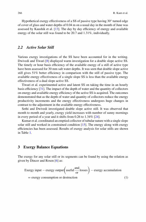
266 R. Kant et al.
Hypothetical exergy effectiveness of a SS of passive type having 30° turned edgeof cover of glass and water depths of 0.04 m on a usual day in the month of June wasassessed by Kaushik et al. [13]. The day by day efficiency of energy and availableenergy of the solar still was found to be 20.7 and 1.31%, individually.
2.2 Active Solar Still
Various exergy investigations of the SS have been accounted for in the writing.Dwivedi and Tiwari [8] displayed warm investigation for a double slope active SS.The timely or hour basis efficiency of the available energy of a still of active typehave been assessed for 30 mm salt water depths. It was seen that double slope activestill gives 51% better efficiency in comparison with the still of passive type. Theavailable energy effectiveness of a single slope SS is less than the available energyeffectiveness of a dual slope active SS.
Tiwari et al. experimented active and latent SS on taking the time in an hourlybasis efficiency [31]. The impact of the depth of water and the quantity of collectorson energy and available energy efficiency of the active SS is acquired. The outcomesdemonstrated that as the depth of water and quantity of collectors reduce the energyproductivity increments and the energy effectiveness undergoes huge changes incontrast to the adjustment in the available energy effectiveness.
Sethi and Dwivedi investigated double slope active still. It was observed thatmonth to month and yearly, exergy yield increases with number of sunny morningsin every period of a year and it shifts from 0.26 to 1.34% [24].
Kumar et al. coordinated an emptied collector of tubular nature with a single slopesolar still and worked in constrained condition [15]. The energy along with exergyefficiencies has been assessed. Results of exergy analysis for solar stills are shownin Table 1.
3 Exergy Balance Equations
The exergy for any solar still or its segments can be found by using the relation asgiven by Dincer and Rosen [6] as:
Exergy input− exergy output
(useful
and
orlosses
)− exergy accumulation
= exergy consumption or destruction (1)
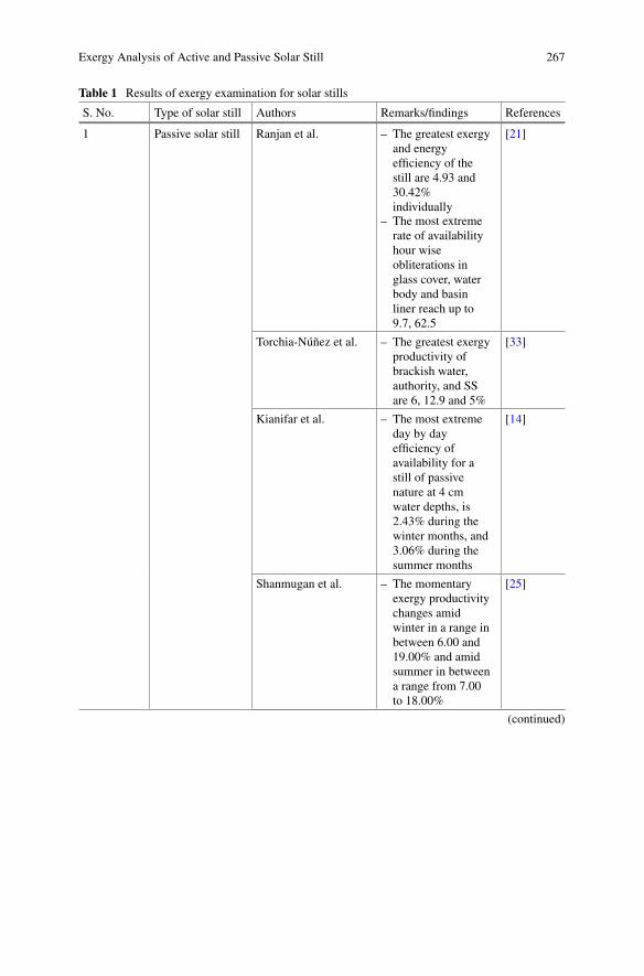
Exergy Analysis of Active and Passive Solar Still 267
Table 1 Results of exergy examination for solar stills
S. No. Type of solar still Authors Remarks/findings References
1 Passive solar still Ranjan et al. – The greatest exergyand energyefficiency of thestill are 4.93 and30.42%individually
– The most extremerate of availabilityhour wiseobliterations inglass cover, waterbody and basinliner reach up to9.7, 62.5
[21]
Torchia-Núñez et al. – The greatest exergyproductivity ofbrackish water,authority, and SSare 6, 12.9 and 5%
[33]
Kianifar et al. – The most extremeday by dayefficiency ofavailability for astill of passivenature at 4 cmwater depths, is2.43% during thewinter months, and3.06% during thesummer months
[14]
Shanmugan et al. – The momentaryexergy productivitychanges amidwinter in a range inbetween 6.00 and19.00% and amidsummer in betweena range from 7.00to 18.00%
[25]
(continued)
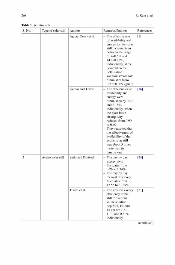
268 R. Kant et al.
Table 1 (continued)
S. No. Type of solar still Authors Remarks/findings References
Aghaei Zoori et al. – The effectivenessof availability andenergy for the solarstill increments inbetween the range3.14–0.5% and44.1–83.3%,individually, at thepoint when thedelta salinesolution stream ratediminishes from0.2 to 0.065 kg/min
[1]
Kumar and Tiwari – The efficiencies ofavailability andenergy werediminished by 36.7and 21.8%,individually, whenthe plate basinabsorptivityreduced from 0.90to 0.60
– They reasoned thatthe effectiveness ofavailability of theactive solar stillwas about 5 timesmore than itspassive one
[16]
2 Active solar still Sethi and Dwivedi – The day by dayexergy yieldfluctuates from0.26 to 1.34%
– The day by daythermal efficiencyfluctuates from13.55 to 31.07%.
[24]
Tiwari et al. – The greatest exergyefficiency of thestill for varioussaline solutiondepths 5, 10, and15 cm are 1.71,1.13, and 0.81%,individually
[31]
(continued)
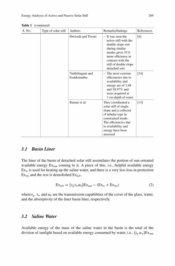
Exergy Analysis of Active and Passive Solar Still 269
Table 1 (continued)
S. No. Type of solar still Authors Remarks/findings References
Dwivedi and Tiwari – It was seen theactive still with thedouble slope sortduring similarmodes gives 51%more efficiency incontrast with thestill of double slopedetached sort
[8]
Vaithilingam andEsakkimuthu
– The most extremeefficiencies due toavailability andenergy are of 3.48and 30.97% andwere acquired at1 cm depth of water
[34]
Kumar et al. They coordinated asolar still of singleslope and a collectorof tubular type inconstrained mode.The efficiencies dueto availability andenergy have beenassessed
[15]
3.1 Basin Liner
The liner of the basin of detached solar still assimilates the portion of sun orientedavailable energy Exsun coming to it. A piece of this, i.e., helpful available energyExw is used for heating up the saline water, and there is a very less loss in protectionExins and the rest is demolished Exd,b.
Exd,b =(τgτwαb
)Exsun − (Exw + Exins) (2)
whereτg, τw and αb are the transmission capabilities of the cover of the glass, water,and the absorptivity of the liner basin liner, respectively.
3.2 Saline Water
Available energy of the mass of the saline water in the basin is the total of thedivision of sunlight based on available energy consumed by water, i.e.,
(tg αw
)Exsun
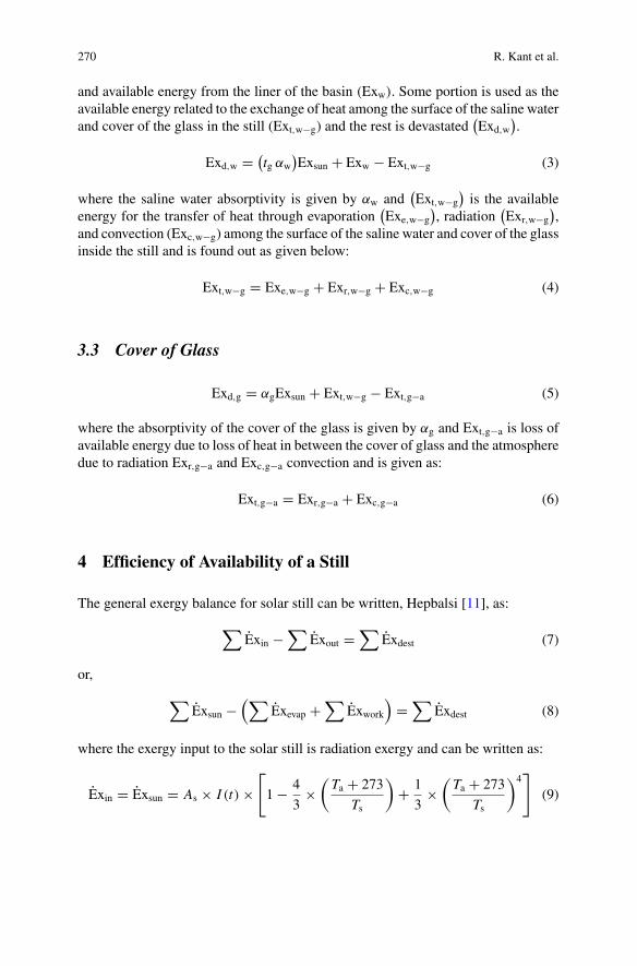
270 R. Kant et al.
and available energy from the liner of the basin (Exw). Some portion is used as theavailable energy related to the exchange of heat among the surface of the saline waterand cover of the glass in the still (Ext,w−g) and the rest is devastated
(Exd,w
).
Exd,w = (tg αw
)Exsun + Exw − Ext,w−g (3)
where the saline water absorptivity is given by αw and(Ext,w−g
)is the available
energy for the transfer of heat through evaporation(Exe,w−g
), radiation
(Exr,w−g
),
and convection (Exc,w−g) among the surface of the saline water and cover of the glassinside the still and is found out as given below:
Ext,w−g = Exe,w−g + Exr,w−g + Exc,w−g (4)
3.3 Cover of Glass
Exd,g = αgExsun + Ext,w−g − Ext,g−a (5)
where the absorptivity of the cover of the glass is given by αg and Ext,g−a is loss ofavailable energy due to loss of heat in between the cover of glass and the atmospheredue to radiation Exr,g−a and Exc,g−a convection and is given as:
Ext,g−a = Exr,g−a + Exc,g−a (6)
4 Efficiency of Availability of a Still
The general exergy balance for solar still can be written, Hepbalsi [11], as:
∑Exin −
∑Exout =
∑Exdest (7)
or,
∑Exsun −
(∑Exevap +
∑Exwork
)=
∑Exdest (8)
where the exergy input to the solar still is radiation exergy and can be written as:
Exin = Exsun = As × I (t) ×[1− 4
3×
(Ta + 273
Ts
)+ 1
3×
(Ta + 273
Ts
)4]
(9)
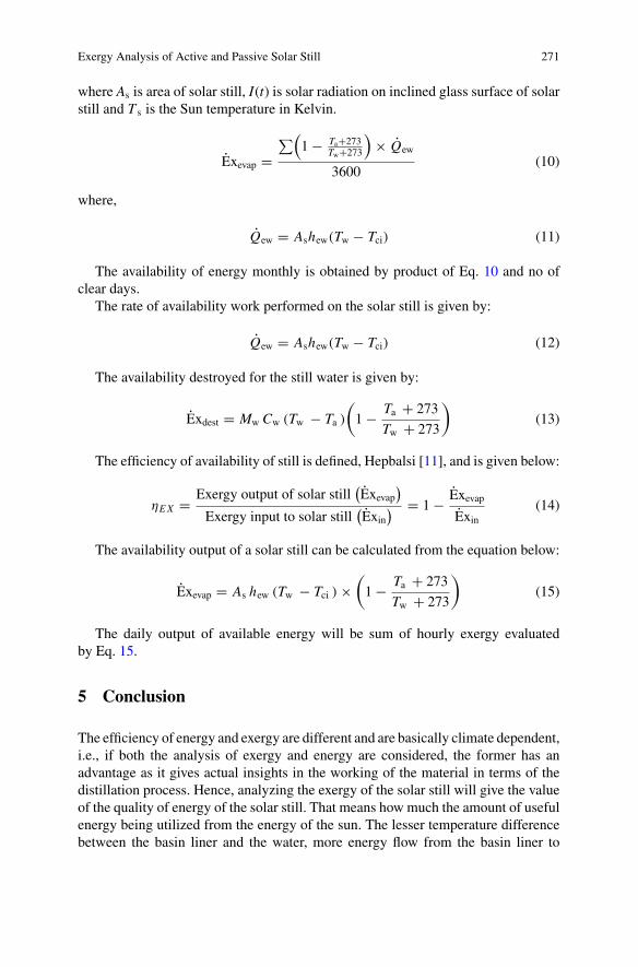
Exergy Analysis of Active and Passive Solar Still 271
where As is area of solar still, I(t) is solar radiation on inclined glass surface of solarstill and T s is the Sun temperature in Kelvin.
Exevap =∑(
1− Ta+273Tw+273
)× Qew
3600(10)
where,
Qew = Ashew(Tw − Tci) (11)
The availability of energy monthly is obtained by product of Eq. 10 and no ofclear days.
The rate of availability work performed on the solar still is given by:
Qew = Ashew(Tw − Tci) (12)
The availability destroyed for the still water is given by:
Exdest = Mw Cw (Tw − Ta )
(1− Ta + 273
Tw + 273
)(13)
The efficiency of availability of still is defined, Hepbalsi [11], and is given below:
ηEX = Exergy output of solar still(Exevap
)Exergy input to solar still
(Exin
) = 1− ExevapExin
(14)
The availability output of a solar still can be calculated from the equation below:
Exevap = As hew (Tw − Tci ) ×(1− Ta + 273
Tw + 273
)(15)
The daily output of available energy will be sum of hourly exergy evaluatedby Eq. 15.
5 Conclusion
The efficiency of energy and exergy are different and are basically climate dependent,i.e., if both the analysis of exergy and energy are considered, the former has anadvantage as it gives actual insights in the working of the material in terms of thedistillation process. Hence, analyzing the exergy of the solar still will give the valueof the quality of energy of the solar still. That means how much the amount of usefulenergy being utilized from the energy of the sun. The lesser temperature differencebetween the basin liner and the water, more energy flow from the basin liner to
272 R. Kant et al.
the water. With the increase in the difference of the temperature the flow of exergyincreases which further decreases the unavailability or unavailable energy. The moreis the temperature difference between the surface of the water and the inner material,the more will the exergy due to evaporation and hence decreases the loss of availableenergy from the left-out water. The difference in the temperature of the glazingsurface and the outer material is very high hence results in less loss of energy in thesystem. During the change in the form of energy from solar to heat, the efficiencyof exergy is low in comparison to instatntaneous efficiency. The amount of loss ofexergy from the liner of the basin to that of the left-out water and the surface of theglazing is maximum. Hence the analysis of exergy for a solar still together with allthe parts is an effective way to design a technically and economically viable solarstill.
References
1. Aghaei Zoori H, Farshchi Tabrizi F, Sarhaddi F, Heshmatnezhad F (2013) Comparison betweenenergy and exergy efficiencies in a weir type cascade solar still. Desalination 325:113–121
2. Ahsan A, Imteaz M, Rahman A, Yusuf B, Fukuhara T (2012) Design, fabrication and perfor-mance analysis of an improved solar still. Desalination 292:105–112
3. Dehghan AA, Afshari A, Rahbar N (2015) Thermal modeling and exergetic analysis of athermoelectric assisted solar still. Sol Energy 115:277–288
4. Deniz E (2013)An investigation of some of the parameters involved in inclined solar distillationsystems. Environ Prog Sustain Energy 32(2):350–354
5. Dev R, Singh HN, Tiwari GN (2011) Characteristic equation of double slope passive solar still.Desalination 267(2–3):261–266
6. Dincer I, Rosen MA (2007) Exergy, environment and sustainable development. In: Exergy, pp36–59
7. Dwivedi VK, Tiwari GN (2008) Annual energy and exergy analysis of single and double slopepassive solar stills. Trends Appl Sci Res 3:225–241
8. Dwivedi VK, Tiwari GN (2010) Experimental validation of thermal model of a double slopeactive solar still under natural circulation mode. Desalination 250(1):49–55
9. Eldalil KMS (2010) Improving the performance of solar still using vibratory harmonic effect.Desalination 251(1–3):3–11
10. Farahat S, Sarhaddi F, Ajam H (2009) Exergetic optimization of flat plate solar collectors.Renew Energy 34(4):1169–1174
11. Hepbalsi A (2006) A key review on exergetic analysis and assessment of renewable energyresources for a sustainable future. Renew Sustain Energy Rev 12:593–661
12. Kabeel AE, Hamed MH, Omara ZM, Sharshir SW (2014) Experimental study of ahumidification-dehumidification solar technique by natural and forced air circulation. Energy68:218–228
13. Kaushik SC, Ranjan KR, Panwar NL (2013) Optimum exergy efficiency of single-effect idealpassive solar stills. Energ Effi 6(3):595–606
14. Kianifar A, Zeinali Heris S, Mahian O (2012) Exergy and economic analysis of a pyramid-shaped solar water purification system: active and passive cases. Energy 38(1):31–36
15. Kumar S, Dubey A, Tiwari GN (2014) A solar still augmented with an evacuated tube collectorin forced mode. Desalination 347:15–24
16. Kumar S, Tiwari GN (2011) Analytical expression for instantaneous exergy efficiency of ashallow basin passive solar still. Int J Therm Sci 50(12):2543–2549
17. Kwatra HS (1996) Performance of a solar still: predicted effect of enhanced evaporation areaon yield and evaporation temperature. Sol Energy 56(3):261–266
Exergy Analysis of Active and Passive Solar Still 273
18. Malik MAS, Tiwari GN, Kumar A, Sodha MS (1982) Solar distillation. Pergamon Press,Oxford, UK
19. Nematollahi F, Rahimi A, Gheinani TT (2013) Experimental and theoretical energy and exergyanalysis for a solar desalination system. Desalination 317:23–31
20. Park SR, Pandey AK, Tyagi VV, Tyagi SK (2014) Energy and exergy analysis of typicalrenewable energy systems. Renew Sustain Energy Rev 30:105–123
21. Ranjan KR, Kaushik SC, Panwar NL (2013) Energy and exergy analysis of passive solardistillation systems. Int J Low-Carbon Technol ctt069
22. Rant Z (1956) Exergy, a new word for “technical available work”. Forschung auf dem Gebietedes Ingenieurwesens 22:36–37 (in German)
23. Saidur R, Boroumandjazi G, Mekhlif S, Jameel M (2012) Exergy analysis of solar energyapplications. Renew Sustain Energy Rev 16(1):350–356
24. Sethi AK, Dwivedi VK (2013) Exergy analysis of double slope active solar still under forcedcirculation mode. Desalin Water Treat 51(40–42):7394–7400
25. Shanmugan S, Manikandan V, Shanmugasundaram K, Janarathanan B, Chandrasekaran J(2012) Energy and exergy analysis of single slope single basin solar still. Int J Ambient Energy33(3):142–151
26. Szargut J (1980) International progress in second law analysis. Energy 5(8–9):709–71827. Tanaka H (2009) Effect of inclination of external reflector of basin type still in summer. Desali-
nation 242(1–3):205–21428. Tiris C, Tiris M, Erdalli Y, SohmenM (1998) Experimental studies on a solar still coupled with
a flat-plate collector and a single basin still. Energy Convers Manag 39(8):853–85629. Tiwari AK, Tiwari GN (2005) Effect of the condensing cover’s slope on internal heat and mass
transfer in distillation: an indoor simulation. Desalination 180(1–3):73–8830. Tiwari AK, Tiwari GN (2006) Effect of water depths on heat and mass transfer in a passive
solar still: in summer climatic condition. Desalination 195(1–3):78–9431. Tiwari GN, Dimri V, Chel A (2009) Parametric study of an active and passive solar distillation
system: energy and exergy analysis. Desalination 242(1–3):1–1832. Tiwari GN, Sahota L (2017) Review on the energy and economic efficiencies of passive and
active solar distillation systems. Desalination 401:151–17933. Torchia-Núñez JC, Porta-Gándara MA, Cervantes-de Gortari JG (2008) Exergy analysis of a
passive solar still. Renew Energy 33(4):608–61634. Vaithilingam S, Esakkimuthu GS (2014) Energy and exergy analysis of single slope passive
solar still: an experimental investigation. Desalin Water Treat 55(6):1433–1444
Effect of Insulation on Energyand Exergy Effectiveness of a SolarPhotovoltaic Panel Incorporated InclinedSolar Still—An ExperimentalInvestigation
A. Muthu Manokar, M. Vimala, D. Prince Winston,Ravishankar Sathyamurthy and A. E. Kabeel
Abstract This manuscript brings out with an impact of insulation on energy andexergy effectiveness of a solar photovoltaic panel incorporated inclined solar still.This research is mainly focuses on the studies of the solar still performance fromthe different parameter such as solar still yield, thermal efficiency, exergy efficiency,solar panel electrical, exergy and thermal efficiency and overall daily thermal andexergy efficiency of the solar panel integrated inclined solar still. The maximumdistilled water of 6.2 kg was achieved as the solar panel integrated inclined still withthe bottom and the sidewall insulation. The daily yield of 3.3, 4.1 and 6.2 kg, the dailyenergy effectiveness of 31.32, 38.81, and 57.88 and the daily exergy effectiveness of1.72, 2.21, and 4.61%was obtained from the solar panel integrated solar still without,with the sidewall, and with the bottom and sidewall insulation, respectively.
Keywords PV panel integrated inclined solar still · Enhancement of still yield ·Energy and exergy efficiency
A. M. Manokar (B)Department of Mechanical Engineering, BS Abdur Rahman CrescentInstitute of Science and Technology, Chennai 600048, Indiae-mail: [email protected]
M. VimalaDepartment of Electrical and Electronics Engineering, RMK EngineeringCollege, Chennai 600206, India
D. P. WinstonDepartment of Electrical and Electronics Engineering, KamarajCollege of Engineering and Technology, Virudhunagar 626001, India
R. SathyamurthyDepartment of Automobile Engineering, Hindustan Institute of Technologyand Science, Chennai 603103, Tamil Nadu, India
R. Sathyamurthy · A. E. KabeelMechanical Power Engineering Department, Faculty of Engineering, TantaUniversity, Tanta, Egypt
© Springer Nature Singapore Pte Ltd. 2019A. Kumar and O. Prakash (eds.), Solar Desalination Technology,Green Energy and Technology, https://doi.org/10.1007/978-981-13-6887-5_13
275
276 A. M. Manokar et al.
Abbreviations
CSS Conventional solar stillEHTC Evaporative heat transfer coefficientISS Inclined solar stillPV/T Photovoltaic thermalPV-ISS PV panel integrated inclined solar still
Nomenclature
A Area (m2)Exinput Exergy input of the PV-ISS (W/m2)Exoutput Exergy output of the PV-ISS (W/m2)h Heat transfer coefficient (W/m2K)I Current (A)I(t) Solar intensity (W/m2)L Latent heat of vaporization (kJ/kg K)M Hourly yield (kg/m2 h)P Partial vapor pressure (N/m2)T Temperature (°C)V Voltage (V)η Efficiency (%)
Subscript
a Ambientc Convectived Dailye Evaporativeg Glassgi Inner glassoverall, exe Overall exergypv Photovoltaics Surface area of condensing coverw Water
Effect of Insulation on Energy and Exergy Effectiveness … 277
1 Introduction
Due to the crisis in water, several desalination processes based on renewable energymethods were developed in order tomeet up the demand of getting fresh intakewater.Over the past few decades, the efficient and more economical solar still technologieswere developed. The design and fabrication of a conventional solar still (CSS) arevery simple and require less maintenance. The basin is constructed with locallyavailable materials and fabricated in the structure of right angle triangle, and a glassis covered over it. In order to increase the absorptivity of basin material, it is coatedwith black paint and to avoid the loss of heat from the basin to the ambient, materialsuch as wood and sawdust is used as thermal insulators. Inside the basin, enoughspaces were provided to fill the brackish or saline water while the solar intensity isabsorbed bywater for quick evaporation from the top liner. Due to the partial pressuredeveloped inside the basin, the evaporated water reach the inner glass cover surfaceto get condensed by the ambient parameters. The water droplets thus formed on thecollector cover gets condensed and collected in a distillate collector which is keptat the end of the collector cover. The distillate collected in the distillate collectorglides through the inclination provided, and freshwater is collected in the separatecalibrated flask. The main drawback of CSS is its lower yield and poor latent heat ofcondensation to the surrounding. To overcome the above difficulties, several designconfigurations were incorporated to improve the yield of the CSS. To improve theproductivity, different modifications in a solar still were made. Inclined Solar Still(ISS) is one such modified form of CSS. However, limited progress was made in theimprovement of inclined still [1–14]. Inclined solar still has the following additionalfeatures incorporated to its design such as flexibility in inclination angle increasedeffective area, the direct projection of solar intensity toward basin, increased thelength of flowing water, an increased retention time of flowing water and higherevaporation rate. All these features improve the performance of ISS as compared toCSS [15]. Researchers have take several efforts in the modification of the ISS forhigh productivity and reported that wick-type ISS are effective [16].
Improvement techniques in solar energy-based desalination approaches areresearched universally, and novel approaches are grown-up regularly. One such pri-mary improvement techniques are the PV panel coupled with the solar still andcollector or concentrator to enhance the electrical power and efficiency of the panel.It is economical, effortless, and simple to fix especially in remote areas. Com-prehensive reviews of improvement techniques in renewable energy-based desali-nation techniques were studied [17–20]. From the detailed review, it was initiatethat the solar panel integrated with solar still can give the distilled yield of about6–12 L/m2/day. Impact of insulation thickness is studied by Khalifa and Hamood[21], and effect of insulation on solar still production is experimentally investigatedby Elango and Murugavel [22] and Al-Karaghouli and Alnaser [23]. Manokar et al.[24, 25] researched the PV panel integrated inclined solar still performance fromthe aspect of solar still yield, exergy and thermal efficiency, and PV panel electricalpower production capacity and efficiency. In this manuscript, the exergy and thermal
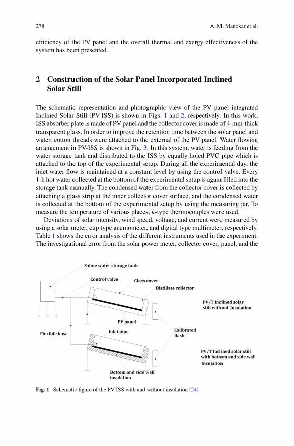
278 A. M. Manokar et al.
efficiency of the PV panel and the overall thermal and exergy effectiveness of thesystem has been presented.
2 Construction of the Solar Panel Incorporated InclinedSolar Still
The schematic representation and photographic view of the PV panel integratedInclined Solar Still (PV-ISS) is shown in Figs. 1 and 2, respectively. In this work,ISS absorber plate is made of PV panel and the collector cover is made of 4-mm-thicktransparent glass. In order to improve the retention time between the solar panel andwater, cotton threads were attached to the external of the PV panel. Water flowingarrangement in PV-ISS is shown in Fig. 3. In this system, water is feeding from thewater storage tank and distributed to the ISS by equally holed PVC pipe which isattached to the top of the experimental setup. During all the experimental day, theinlet water flow is maintained at a constant level by using the control valve. Every1-h hot water collected at the bottom of the experimental setup is again filled into thestorage tank manually. The condensed water from the collector cover is collected byattaching a glass strip at the inner collector cover surface, and the condensed wateris collected at the bottom of the experimental setup by using the measuring jar. Tomeasure the temperature of various places, k-type thermocouples were used.
Deviations of solar intensity, wind speed, voltage, and current were measured byusing a solar meter, cup type anemometer, and digital type multimeter, respectively.Table 1 shows the error analysis of the different instruments used in the experiment.The investigational error from the solar power meter, collector cover, panel, and the
Fig. 1 Schematic figure of the PV-ISS with and without insulation [24]
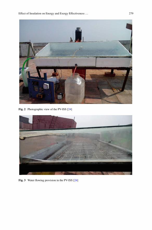
Effect of Insulation on Energy and Exergy Effectiveness … 279
Fig. 2 Photographic view of the PV-ISS [24]
Fig. 3 Water flowing provision in the PV-ISS [24]
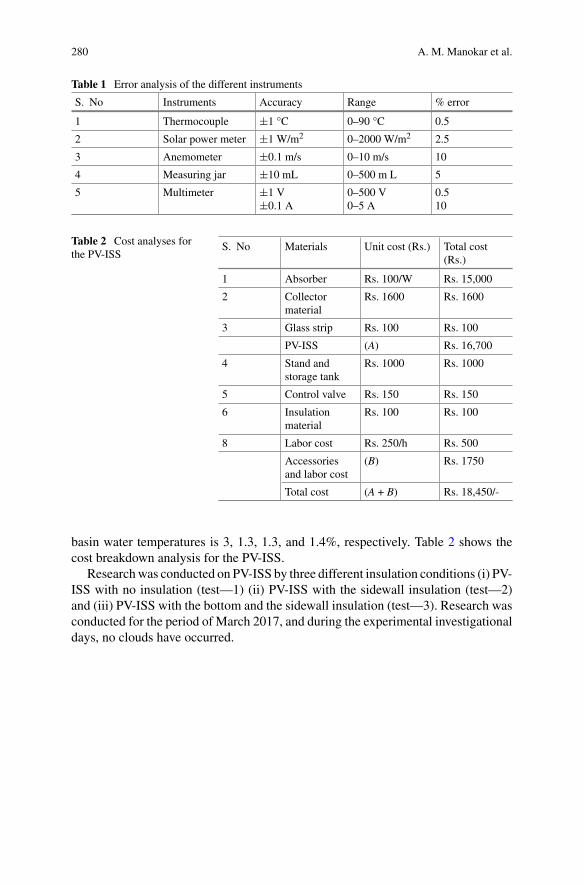
280 A. M. Manokar et al.
Table 1 Error analysis of the different instruments
S. No Instruments Accuracy Range % error
1 Thermocouple ±1 °C 0–90 °C 0.5
2 Solar power meter ±1 W/m2 0–2000 W/m2 2.5
3 Anemometer ±0.1 m/s 0–10 m/s 10
4 Measuring jar ±10 mL 0–500 m L 5
5 Multimeter ±1 V±0.1 A
0–500 V0–5 A
0.510
Table 2 Cost analyses forthe PV-ISS
S. No Materials Unit cost (Rs.) Total cost(Rs.)
1 Absorber Rs. 100/W Rs. 15,000
2 Collectormaterial
Rs. 1600 Rs. 1600
3 Glass strip Rs. 100 Rs. 100
PV-ISS (A) Rs. 16,700
4 Stand andstorage tank
Rs. 1000 Rs. 1000
5 Control valve Rs. 150 Rs. 150
6 Insulationmaterial
Rs. 100 Rs. 100
8 Labor cost Rs. 250/h Rs. 500
Accessoriesand labor cost
(B) Rs. 1750
Total cost (A + B) Rs. 18,450/-
basin water temperatures is 3, 1.3, 1.3, and 1.4%, respectively. Table 2 shows thecost breakdown analysis for the PV-ISS.
Researchwas conducted on PV-ISS by three different insulation conditions (i) PV-ISS with no insulation (test—1) (ii) PV-ISS with the sidewall insulation (test—2)and (iii) PV-ISS with the bottom and the sidewall insulation (test—3). Research wasconducted for the period of March 2017, and during the experimental investigationaldays, no clouds have occurred.
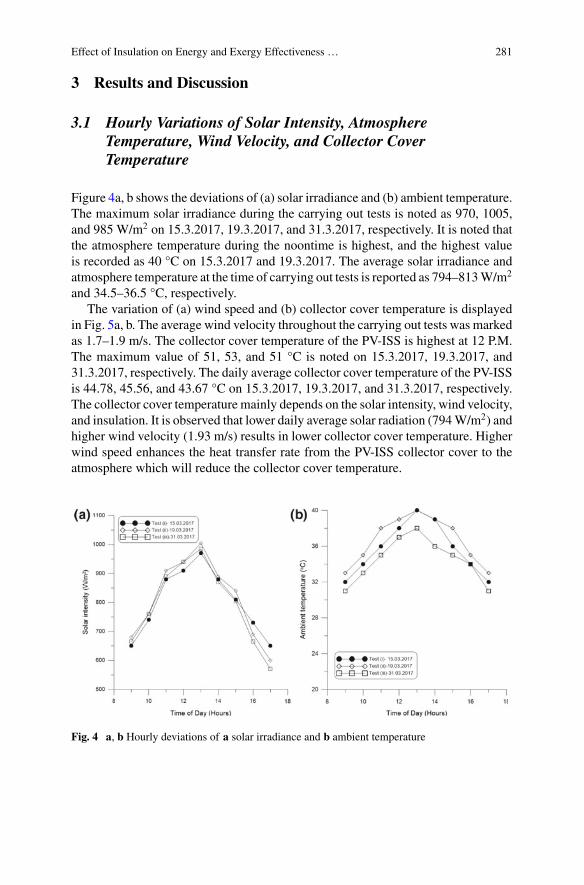
Effect of Insulation on Energy and Exergy Effectiveness … 281
3 Results and Discussion
3.1 Hourly Variations of Solar Intensity, AtmosphereTemperature, Wind Velocity, and Collector CoverTemperature
Figure 4a, b shows the deviations of (a) solar irradiance and (b) ambient temperature.The maximum solar irradiance during the carrying out tests is noted as 970, 1005,and 985 W/m2 on 15.3.2017, 19.3.2017, and 31.3.2017, respectively. It is noted thatthe atmosphere temperature during the noontime is highest, and the highest valueis recorded as 40 °C on 15.3.2017 and 19.3.2017. The average solar irradiance andatmosphere temperature at the time of carrying out tests is reported as 794–813W/m2
and 34.5–36.5 °C, respectively.The variation of (a) wind speed and (b) collector cover temperature is displayed
in Fig. 5a, b. The average wind velocity throughout the carrying out tests was markedas 1.7–1.9 m/s. The collector cover temperature of the PV-ISS is highest at 12 P.M.The maximum value of 51, 53, and 51 °C is noted on 15.3.2017, 19.3.2017, and31.3.2017, respectively. The daily average collector cover temperature of the PV-ISSis 44.78, 45.56, and 43.67 °C on 15.3.2017, 19.3.2017, and 31.3.2017, respectively.The collector cover temperature mainly depends on the solar intensity, wind velocity,and insulation. It is observed that lower daily average solar radiation (794W/m2) andhigher wind velocity (1.93 m/s) results in lower collector cover temperature. Higherwind speed enhances the heat transfer rate from the PV-ISS collector cover to theatmosphere which will reduce the collector cover temperature.
Fig. 4 a, b Hourly deviations of a solar irradiance and b ambient temperature
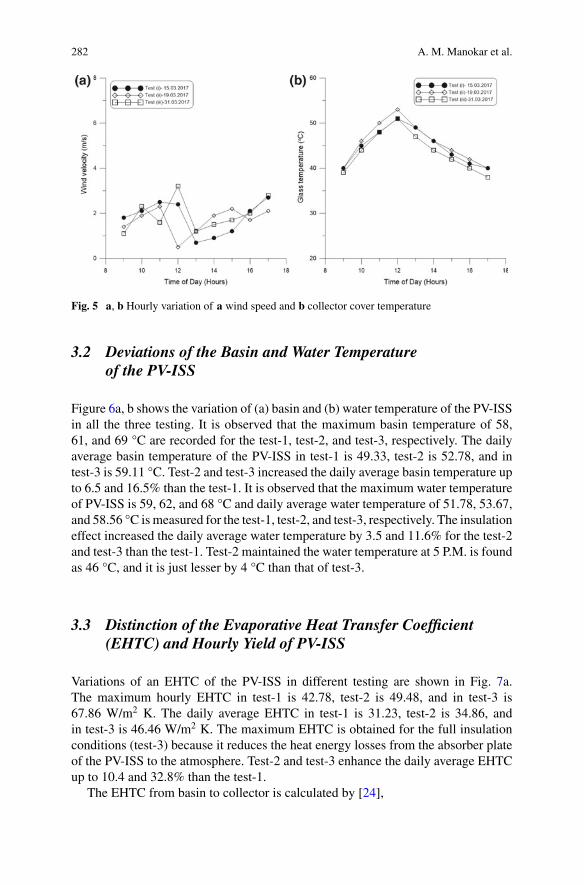
282 A. M. Manokar et al.
Fig. 5 a, b Hourly variation of a wind speed and b collector cover temperature
3.2 Deviations of the Basin and Water Temperatureof the PV-ISS
Figure 6a, b shows the variation of (a) basin and (b) water temperature of the PV-ISSin all the three testing. It is observed that the maximum basin temperature of 58,61, and 69 °C are recorded for the test-1, test-2, and test-3, respectively. The dailyaverage basin temperature of the PV-ISS in test-1 is 49.33, test-2 is 52.78, and intest-3 is 59.11 °C. Test-2 and test-3 increased the daily average basin temperature upto 6.5 and 16.5% than the test-1. It is observed that the maximum water temperatureof PV-ISS is 59, 62, and 68 °C and daily average water temperature of 51.78, 53.67,and 58.56 °C ismeasured for the test-1, test-2, and test-3, respectively. The insulationeffect increased the daily average water temperature by 3.5 and 11.6% for the test-2and test-3 than the test-1. Test-2 maintained the water temperature at 5 P.M. is foundas 46 °C, and it is just lesser by 4 °C than that of test-3.
3.3 Distinction of the Evaporative Heat Transfer Coefficient(EHTC) and Hourly Yield of PV-ISS
Variations of an EHTC of the PV-ISS in different testing are shown in Fig. 7a.The maximum hourly EHTC in test-1 is 42.78, test-2 is 49.48, and in test-3 is67.86 W/m2 K. The daily average EHTC in test-1 is 31.23, test-2 is 34.86, andin test-3 is 46.46 W/m2 K. The maximum EHTC is obtained for the full insulationconditions (test-3) because it reduces the heat energy losses from the absorber plateof the PV-ISS to the atmosphere. Test-2 and test-3 enhance the daily average EHTCup to 10.4 and 32.8% than the test-1.
The EHTC from basin to collector is calculated by [24],
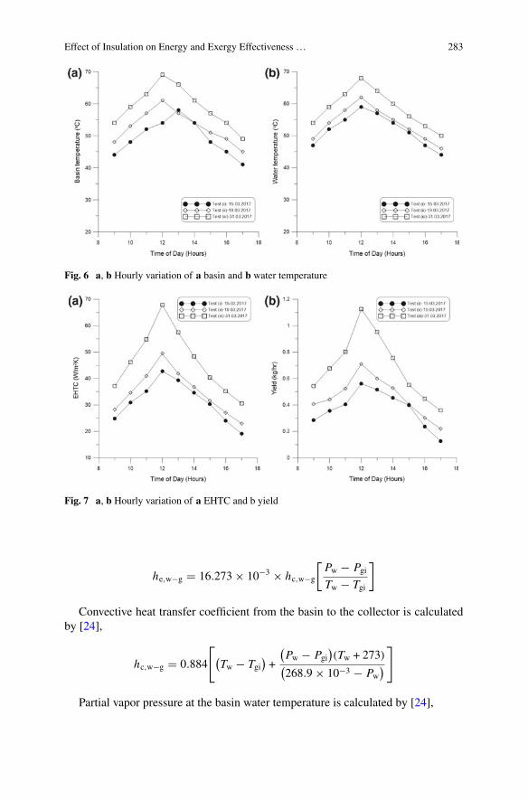
Effect of Insulation on Energy and Exergy Effectiveness … 283
Fig. 6 a, b Hourly variation of a basin and b water temperature
Fig. 7 a, b Hourly variation of a EHTC and b yield
he,w−g � 16.273 × 10⁻³ × hc,w−g
[Pw − PgiTw − Tgi
]
Convective heat transfer coefficient from the basin to the collector is calculatedby [24],
hc,w−g � 0.884
[(Tw − Tgi
)+
(Pw − Pgi
)(Tw + 273)(
268.9 × 10⁻³ − Pw)]
Partial vapor pressure at the basin water temperature is calculated by [24],
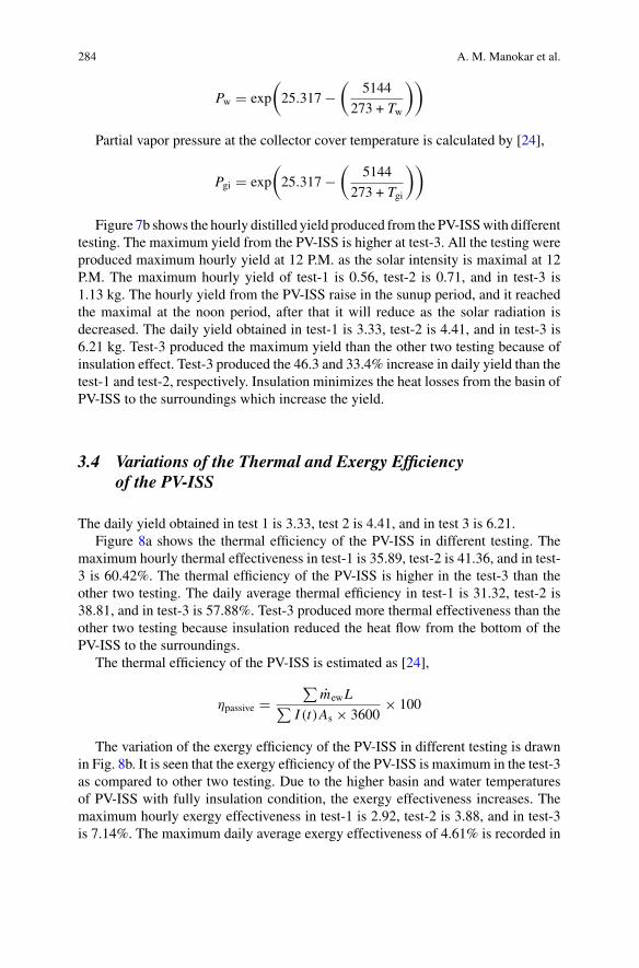
284 A. M. Manokar et al.
Pw � exp
(25.317 −
(5144
273 + Tw
))
Partial vapor pressure at the collector cover temperature is calculated by [24],
Pgi � exp
(25.317 −
(5144
273 + Tgi
))
Figure 7b shows the hourly distilled yield produced from the PV-ISSwith differenttesting. The maximum yield from the PV-ISS is higher at test-3. All the testing wereproduced maximum hourly yield at 12 P.M. as the solar intensity is maximal at 12P.M. The maximum hourly yield of test-1 is 0.56, test-2 is 0.71, and in test-3 is1.13 kg. The hourly yield from the PV-ISS raise in the sunup period, and it reachedthe maximal at the noon period, after that it will reduce as the solar radiation isdecreased. The daily yield obtained in test-1 is 3.33, test-2 is 4.41, and in test-3 is6.21 kg. Test-3 produced the maximum yield than the other two testing because ofinsulation effect. Test-3 produced the 46.3 and 33.4% increase in daily yield than thetest-1 and test-2, respectively. Insulation minimizes the heat losses from the basin ofPV-ISS to the surroundings which increase the yield.
3.4 Variations of the Thermal and Exergy Efficiencyof the PV-ISS
The daily yield obtained in test 1 is 3.33, test 2 is 4.41, and in test 3 is 6.21.Figure 8a shows the thermal efficiency of the PV-ISS in different testing. The
maximum hourly thermal effectiveness in test-1 is 35.89, test-2 is 41.36, and in test-3 is 60.42%. The thermal efficiency of the PV-ISS is higher in the test-3 than theother two testing. The daily average thermal efficiency in test-1 is 31.32, test-2 is38.81, and in test-3 is 57.88%. Test-3 produced more thermal effectiveness than theother two testing because insulation reduced the heat flow from the bottom of thePV-ISS to the surroundings.
The thermal efficiency of the PV-ISS is estimated as [24],
ηpassive �∑
mewL∑I (t)As × 3600
× 100
The variation of the exergy efficiency of the PV-ISS in different testing is drawnin Fig. 8b. It is seen that the exergy efficiency of the PV-ISS is maximum in the test-3as compared to other two testing. Due to the higher basin and water temperaturesof PV-ISS with fully insulation condition, the exergy effectiveness increases. Themaximum hourly exergy effectiveness in test-1 is 2.92, test-2 is 3.88, and in test-3is 7.14%. The maximum daily average exergy effectiveness of 4.61% is recorded in
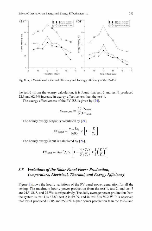
Effect of Insulation on Energy and Exergy Effectiveness … 285
Fig. 8 a, b Variation of a thermal efficiency and b exergy efficiency of the PV-ISS
the test-3. From the exergy calculation, it is found that test-2 and test-3 produced22.3 and 62.7% increase in exergy effectiveness than the test-1.
The exergy effectiveness of the PV-ISS is given by [24],
ηoverall,exe �∑
Exoutput∑Exinput
The hourly exergy output is calculated by [24],
Exoutput � mewL fg
3600×
[1 − Ta
Tw
]
The hourly exergy input is calculated by [24],
Exinput � Aw I′(t) ×
[1 − 4
3
(TaTs
)+1
3
(TaTs
)4]
3.5 Variations of the Solar Panel Power Production,Temperature, Electrical, Thermal, and Exergy Efficiency
Figure 9 shows the hourly variations of the PV panel power generation for all thetesting. The maximum hourly power production from the test-1, test-2, and test-3are 94.5, 88.8, and 72 Watts, respectively. The daily average power production fromthe system is test-1 is 67.80, test-2 is 59.09, and in test-3 is 50.2 W. It is observedthat test-1 produced 12.85 and 25.96% higher power production than the test-2 and
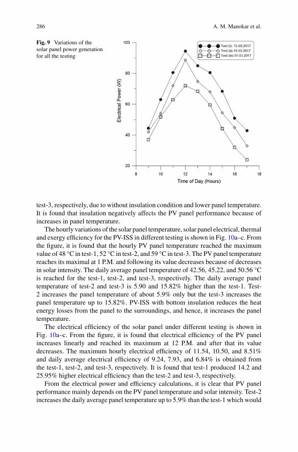
286 A. M. Manokar et al.
Fig. 9 Variations of thesolar panel power generationfor all the testing
test-3, respectively, due to without insulation condition and lower panel temperature.It is found that insulation negatively affects the PV panel performance because ofincreases in panel temperature.
The hourly variations of the solar panel temperature, solar panel electrical, thermaland exergy efficiency for the PV-ISS in different testing is shown in Fig. 10a–c. Fromthe figure, it is found that the hourly PV panel temperature reached the maximumvalue of 48 °C in test-1, 52 °C in test-2, and 59 °C in test-3. The PV panel temperaturereaches its maximal at 1 P.M. and following its value decreases because of decreasesin solar intensity. The daily average panel temperature of 42.56, 45.22, and 50.56 °Cis reached for the test-1, test-2, and test-3, respectively. The daily average paneltemperature of test-2 and test-3 is 5.90 and 15.82% higher than the test-1. Test-2 increases the panel temperature of about 5.9% only but the test-3 increases thepanel temperature up to 15.82%. PV-ISS with bottom insulation reduces the heatenergy losses from the panel to the surroundings, and hence, it increases the paneltemperature.
The electrical efficiency of the solar panel under different testing is shown inFig. 10a–c. From the figure, it is found that electrical efficiency of the PV panelincreases linearly and reached its maximum at 12 P.M. and after that its valuedecreases. The maximum hourly electrical efficiency of 11.54, 10.50, and 8.51%and daily average electrical efficiency of 9.24, 7.93, and 6.84% is obtained fromthe test-1, test-2, and test-3, respectively. It is found that test-1 produced 14.2 and25.95% higher electrical efficiency than the test-2 and test-3, respectively.
From the electrical power and efficiency calculations, it is clear that PV panelperformance mainly depends on the PV panel temperature and solar intensity. Test-2increases the daily average panel temperature up to 5.9% than the test-1 which would
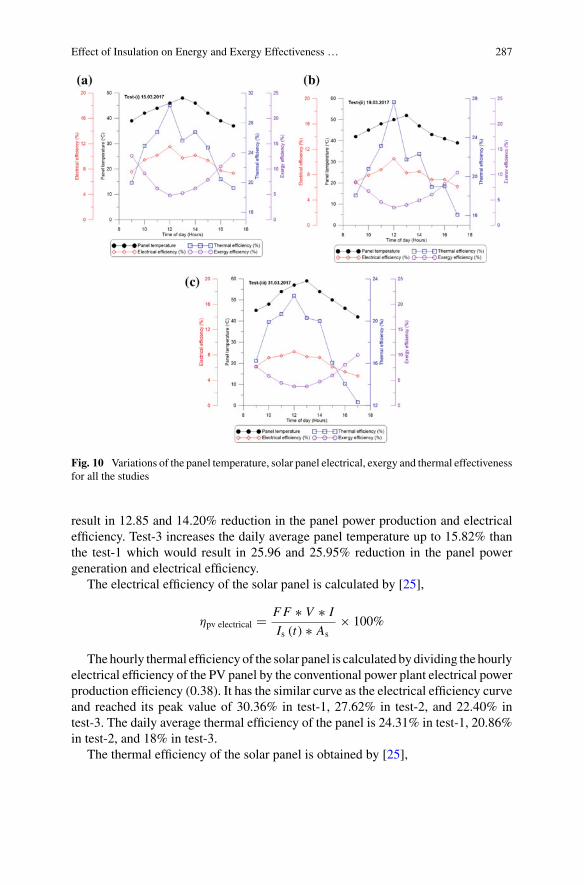
Effect of Insulation on Energy and Exergy Effectiveness … 287
Fig. 10 Variations of the panel temperature, solar panel electrical, exergy and thermal effectivenessfor all the studies
result in 12.85 and 14.20% reduction in the panel power production and electricalefficiency. Test-3 increases the daily average panel temperature up to 15.82% thanthe test-1 which would result in 25.96 and 25.95% reduction in the panel powergeneration and electrical efficiency.
The electrical efficiency of the solar panel is calculated by [25],
ηpv electrical � FF ∗ V ∗ I
Is (t) ∗ As× 100%
Thehourly thermal efficiency of the solar panel is calculated by dividing the hourlyelectrical efficiency of the PV panel by the conventional power plant electrical powerproduction efficiency (0.38). It has the similar curve as the electrical efficiency curveand reached its peak value of 30.36% in test-1, 27.62% in test-2, and 22.40% intest-3. The daily average thermal efficiency of the panel is 24.31% in test-1, 20.86%in test-2, and 18% in test-3.
The thermal efficiency of the solar panel is obtained by [25],
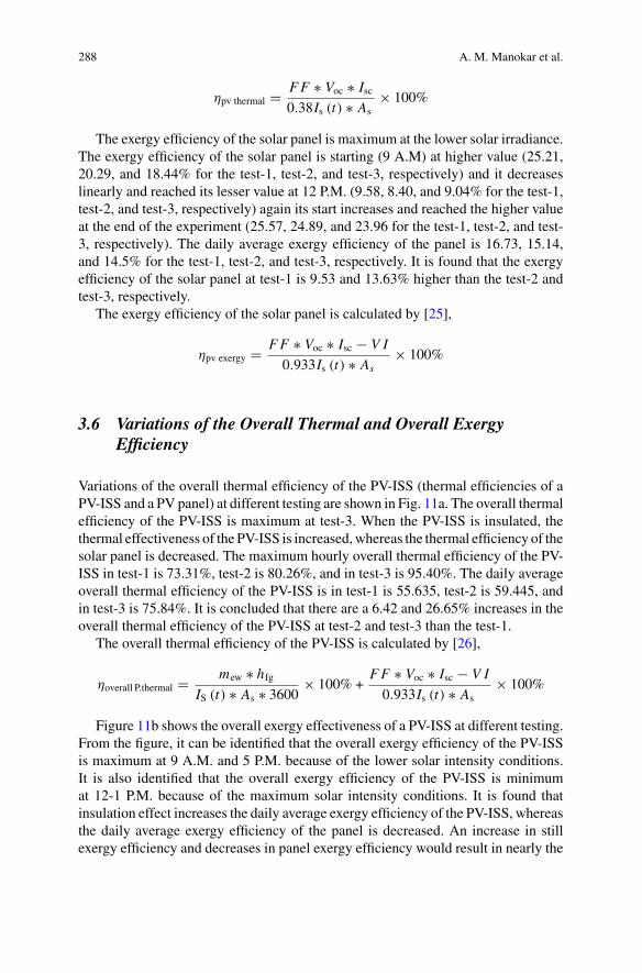
288 A. M. Manokar et al.
ηpv thermal � FF ∗ Voc ∗ Isc0.38Is (t) ∗ As
× 100%
The exergy efficiency of the solar panel is maximum at the lower solar irradiance.The exergy efficiency of the solar panel is starting (9 A.M) at higher value (25.21,20.29, and 18.44% for the test-1, test-2, and test-3, respectively) and it decreaseslinearly and reached its lesser value at 12 P.M. (9.58, 8.40, and 9.04% for the test-1,test-2, and test-3, respectively) again its start increases and reached the higher valueat the end of the experiment (25.57, 24.89, and 23.96 for the test-1, test-2, and test-3, respectively). The daily average exergy efficiency of the panel is 16.73, 15.14,and 14.5% for the test-1, test-2, and test-3, respectively. It is found that the exergyefficiency of the solar panel at test-1 is 9.53 and 13.63% higher than the test-2 andtest-3, respectively.
The exergy efficiency of the solar panel is calculated by [25],
ηpv exergy � FF ∗ Voc ∗ Isc − V I
0.933Is (t) ∗ As× 100%
3.6 Variations of the Overall Thermal and Overall ExergyEfficiency
Variations of the overall thermal efficiency of the PV-ISS (thermal efficiencies of aPV-ISS and a PV panel) at different testing are shown in Fig. 11a. The overall thermalefficiency of the PV-ISS is maximum at test-3. When the PV-ISS is insulated, thethermal effectiveness of the PV-ISS is increased,whereas the thermal efficiency of thesolar panel is decreased. The maximum hourly overall thermal efficiency of the PV-ISS in test-1 is 73.31%, test-2 is 80.26%, and in test-3 is 95.40%. The daily averageoverall thermal efficiency of the PV-ISS is in test-1 is 55.635, test-2 is 59.445, andin test-3 is 75.84%. It is concluded that there are a 6.42 and 26.65% increases in theoverall thermal efficiency of the PV-ISS at test-2 and test-3 than the test-1.
The overall thermal efficiency of the PV-ISS is calculated by [26],
ηoverall P.thermal � mew ∗ hfgIS (t) ∗ As ∗ 3600
× 100% +FF ∗ Voc ∗ Isc − V I
0.933Is (t) ∗ As× 100%
Figure 11b shows the overall exergy effectiveness of a PV-ISS at different testing.From the figure, it can be identified that the overall exergy efficiency of the PV-ISSis maximum at 9 A.M. and 5 P.M. because of the lower solar intensity conditions.It is also identified that the overall exergy efficiency of the PV-ISS is minimumat 12-1 P.M. because of the maximum solar intensity conditions. It is found thatinsulation effect increases the daily average exergy efficiency of the PV-ISS, whereasthe daily average exergy efficiency of the panel is decreased. An increase in stillexergy efficiency and decreases in panel exergy efficiency would result in nearly the
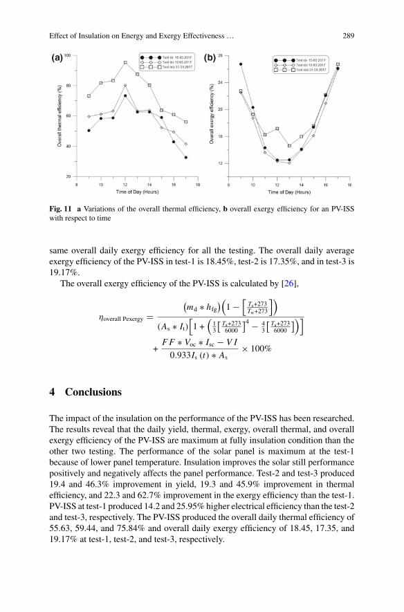
Effect of Insulation on Energy and Exergy Effectiveness … 289
Fig. 11 a Variations of the overall thermal efficiency, b overall exergy efficiency for an PV-ISSwith respect to time
same overall daily exergy efficiency for all the testing. The overall daily averageexergy efficiency of the PV-ISS in test-1 is 18.45%, test-2 is 17.35%, and in test-3 is19.17%.
The overall exergy efficiency of the PV-ISS is calculated by [26],
ηoverall Pexergy �(md ∗ hfg
)(1 −
[Ta+273Tw+273
])
(As ∗ It)[1 +
(13
[ Ta+2736000
]4 − 43
[ Ta+2736000
])]
+FF ∗ Voc ∗ Isc − V I
0.933Is (t) ∗ As× 100%
4 Conclusions
The impact of the insulation on the performance of the PV-ISS has been researched.The results reveal that the daily yield, thermal, exergy, overall thermal, and overallexergy efficiency of the PV-ISS are maximum at fully insulation condition than theother two testing. The performance of the solar panel is maximum at the test-1because of lower panel temperature. Insulation improves the solar still performancepositively and negatively affects the panel performance. Test-2 and test-3 produced19.4 and 46.3% improvement in yield, 19.3 and 45.9% improvement in thermalefficiency, and 22.3 and 62.7% improvement in the exergy efficiency than the test-1.PV-ISS at test-1 produced 14.2 and 25.95% higher electrical efficiency than the test-2and test-3, respectively. The PV-ISS produced the overall daily thermal efficiency of55.63, 59.44, and 75.84% and overall daily exergy efficiency of 18.45, 17.35, and19.17% at test-1, test-2, and test-3, respectively.
290 A. M. Manokar et al.
References
1. MuthuManokar A, KalidasaMurugavel K, Esakkimuthu G (2014) Different parameters affect-ing the rate of evaporation and condensation on passive solar still—a review. Renew SustainEnergy Rev 38:309–322
2. Muthu Manokar A, Prince Winston D, Kabeel AE, Sathyamurthy R, Arunkumar T (2018)Different parameter and technique affecting the rate of evaporation on active solar still—areview. Heat Mass Transf 54:593–630
3. Raj SV, Manokar AM (2017) Design and analysis of solar still. Mater Today Proc4(8):9179–9185
4. ManokarAM,VimalaM,WinstonDP,RameshR,SathyamurthyR,NagarajanPK,BharathwaajR (2018) Different parameters affecting the condensation rate on an active solar still—a review.Environ Prog Sustain Energy. https://doi.org/10.1002/ep.12923
5. Kabeel AE, Manokar AM, Sathyamurthy R, Winston DP, El-Agouz SA, Chamkha AJ (2019)A review on different design modifications employed in inclined solar still for enhancing theproductivity. J Solar Energy Eng 141(3):031007
6. Manokar AM, Taamneh Y, Kabeel AE, Sathyamurthy R, Winston DP, Chamkha AJ (2018)Review of different methods employed in pyramidal solar still desalination to augment theyield of freshwater. Desalin Water Treat 136:20–30
7. Manokar AM, Winston DP, Sathyamurthy R, Kabeel AE, Prasath AR (2018) Experimentalinvestigation on pyramid solar still in passive and active mode. Heat Mass Transf 1–14. https://doi.org/10.1007/s00231-018-2483-3
8. Kabeel AE, Sathyamurthy R, Sharshir SW, Muthumanokar A, Panchal H, Prakash N, ... ElKady MS (2019) Effect of water depth on a novel absorber plate of pyramid solar still coatedwith TiO2 nano black paint. J Clean Prod 213:185–191
9. Kumar PN, Manokar AM, Madhu B, Kabeel AE, Arunkumar T, Panchal H, Sathyamurthy R(2017) Experimental investigation on the effect of water mass in triangular pyramid solar stillintegrated to inclined solar still. Groundwater Sustain Dev 5:229–234
10. Panchal H, Taamneh Y, Sathyamurthy R, Kabeel AE, El-Agouz SA, Naveen Kumar P, Bharath-waaj R (2018) Economic and exergy investigation of triangular pyramid solar still integratedto inclined solar still with baffles. Int J Ambient Energy 1–6
11. KabeelAE, TaamnehY, SathyamurthyR,NaveenKumar P,ManokarAM,Arunkumar T (2019)Experimental study on conventional solar still integratedwith inclined solar still under differentwater depth. Heat Transf-Asian Res 48(1):100–114
12. El-AgouzE,KabeelAE,Subramani J,ManokarAM,ArunkumarT,SathyamurthyR,NagarajanPK, Babu DM (2018) Theoretical analysis of continuous heat extraction from absorber of solarstill for improving the productivity. Periodica Polytech Mech Eng 62(3):187–195
13. Madhu B, Balasubramanian E, Sathyamurthy R, Nagarajan PK, Mageshbabu D, BharathwaajR, Manokar AM (2018). Exergy analysis of solar still with sand heat energy storage. ApplSolar Energy 54(3):173–177
14. Madhu B, Balasubramanian E, Kabeel AE, El-Agouz SA, Manokar AM, Prakash N, Sathya-murthy R (2018) Experimental investigation on the effect of sensible heat energy storage in aninclined solar still with baffles. Desalin Water Treat 116:49–56
15. Kaviti AK, Yadav A, Shukla A (2016) Inclined solar still designs: a review. Renew SustainEnergy Rev 54:429–451
16. ManikandanV, ShanmugasundaramK, Shanmugan S, JanarthananB, Chandrasekaran J (2013)Wick type solar stills: a review. Renew Sustain Energy Rev 20:322–335
17. GudeVG,NagamanyN,DengS (2010)Renewable and sustainable approaches for desalination.Renew Sustain Energy Rev 14:2641–2654
18. Byrne Paul et al (2015) A review on the coupling of cooling, desalination and solar photovoltaicsystems. Renew Sustain Energy Rev 47:703–717
19. Sharon H, Reddy KS (2015) A review of solar energy driven desalination technologies. RenewSustain Energy Rev 41:1080–1118
Effect of Insulation on Energy and Exergy Effectiveness … 291
20. Manokar AM,Winston DP, Kabeel AE, El-Agouz SA, Sathyamurthy R, Arunkumar T, MadhuB, Ahsan A (2018) Integrated PV/T solar still—a mini-review. Desalination 435:259–267
21. Khalifa AJN, Hamood AM (2009) Effect of insulation thickness on the productivity of basintype solar stills: an experimental verification under local climate. Energy Convers Manag50(9):2457–2461
22. Elango T, Murugavel KK (2015) The effect of the water depth on the productivity for singleand double basin double slope glass solar stills. Desalination 359:82–91
23. Al-Karaghouli AA, Alnaser WE (2004) Experimental comparative test of the performances ofsingle and double basin solar-stills. Appl Energy 77(3):317–325
24. Manokar AM, Winston DP, Kabeel AE, Sathyamurthy R (2018) Sustainable fresh water andpower production by integrating PV panel in inclined solar still. J Clean Prod 172:2711–2719
25. Manokar AM, Winston DP, Mondol JD, Sathyamurthy R, Kabeel AE, Panchal H (2018) Com-parative study of an inclined solar panel basin solar still in passive and active mode. Sol Energy169:206–216
26. Singh DB, Yadav JK, Dwivedi VK, Kumar S, Tiwari GN, Al-Helal IM (2016) Experimentaltesting of active solar still integrated with two hybrid PVT collectors. Sol Energy 130:207–223
A. Muthu Manokar was born in Thiruthangal, Virudhunagar (Dt), India, in 1989. He receivedB.E. degree in Electrical and Electronics Engineering from Sree Sowdambika College of Engi-neering, Aruppukottai, in 2011, and the M.E. degree in Energy Engineering from National Engi-neering College, Kovilpatti, in 2013. He completed his Ph.D. degree from Anna University, Chen-nai. Currently he is working as a Assistant professor in the department of Mechanical Engi-neering, BS Abdur Rahman Crescent Institute of Science and Technology, Chennai—600 048,India. His research is centered on the areas of Solar Desalination and Nanotechnology applica-tion in the field of solar thermal energy. He has more than five years of teaching experience.He has Published 26 papers in international Journals. He also has 13 International conferencepublications and 04 National conference publications. He was the General Chair of the IEEEInternational Conference on Renewable Energy Research and Application (ICRERA) in Birm-ingham/UK., 3rd International Conference on New Energy and Future Energy System (NEFES2018), Shanghai, China. He was also the Reviewer for leading International Journals—Desali-nation (Elsevier), Environmental Progress & Sustainable Energy (John Wiley & Sons), JordanJournal of Mechanical and Industrial Engineering, The Journal of Engineering Research, Jour-nal of Renewable Energy, Journal of Water Resource and Protection, Journal of Mechanical Sci-ence and Technology (Springer), International Research Journal of Agricultural and Food Sci-ences, Advances in Applied Agricultural Sciences, Journal of Essential Oil Bearing Plants (Taylor& Francis), Current Research in Hydrology and Water Resources, Open Access Journal of Pho-toenergy, International Journal of Petrochemical Science & Engineering. He may be contacted [email protected]
M. Vimala was currently working as an Assistant Professor in R.M.K. Engineering College,Chennai under the Department of Electrical and Electronics Engineering and also pursuing herPh.D. degree in Anna University, Chennai. She was born in Chennai, India, in 1989. She did herB.E. degree in Magna College of Engineering, in 2010 and the M.E Degree under Power Electron-ics and Drives in R.M.K. Engineering College, in 2013. She has more than five years of Teach-ing Experience. Her area of research is Solar Photovoltaic systems. She has published 2 papersin International Journals and also presented papers in 5 International conferences and 3 papers inNational conferences. She is a corporate member of IEI and lifetime member in ISTE. She maybe contacted at [email protected].
D. Prince Winston completed his B.E. Degree in the discipline of Electrical and Electronics Engi-neering in the R.V.S College of Eng. & Tech., Dindugal, in the year 2006. He completed his M.E.
292 A. M. Manokar et al.
Degree in Power Electronics and Drives in Mepco Schlenk Engineering College, Sivakasi, in theyear 2008. He was awarded the Ph.D. degree from Anna University, Chennai, in the year 2013.The title of his Ph.D. thesis is “Certain Investigations on Energy Conservation in AC and DCMotor Drives.” He has about 8 years of teaching experience at various levels. He has 2 years ofresearch experience in the UGCMajor Research Project at Thiagarajar College of Engineering andTechnology, Madurai. He is currently working as Associate Professor in the Dept. of EEE, Kama-raj College of Engineering and Technology, since May 2013. He has published about 50 papersin referred international journals, 12 papers in international conferences, and 6 papers in nationalconferences. He is currently guiding 10 Ph.D. scholars, including 2 full-time scholars, under AnnaUniversity, Chennai. He may be contacted at [email protected].
Dr. Ravishankar Sathyamurthy received his Bachelor in Mechanical Engineering and pursuedhis post-graduate degree in Thermal Engineering at Anna University of Technology, Thirunelveli,in 2012, and received his Ph.D. degree in Mechanical Engineering from Hindustan Institute ofTechnology and Science, Chennai, in 2016. He has published in 80 reputed international journals.His areas of interest include solar desalination, renewable energy technologies, thermal energystorage, nano-materials, bio-diesel, and combustion modeling. He has reviewed more than 200research articles from journals such as Renewable and Sustainable Energy—A Review, Journal ofApplied Fluid Mechanics, International Journal of Renewable Energy Research, Institute of Engi-neers (India): Series C Case Studies in Thermal Engineering, Journal of Solar Energy, and Journalof Energy Research. He may be contacted at [email protected].
Dr. A. E. Kabeel is a Professor in the Department of Mechanical Engineering at the Uni-versity of Tanta, Egypt. He has been Vice Dean for Postgraduate Studies and Research, Fac-ulty of Engineering, at Tanta University, Tanta, from Jun 2016 until now. He was Head of theMechanical Power Engineering Department, Faculty of Engineering, Tanta University, Tanta, fromSeptember June 2013 to 1/6/2016, and Vice Dean for Community Service and Environmen-tal Development, Faculty of Engineering, Tanta University, Tanta, from 2010 to 2013. He hasreceived many scientific awards, the most recent one being the 2014 Shoman Prize for ArabResearchers. His research interests lie in the area of thermal energy science. In recent years,he has focused on better techniques for enhancing thermal processes, especially in cooling anddesalination programs. He has about 220 research publications in international journals and con-ferences. He may be contacted at [email protected]; [email protected].
Latent Heat Storage for Solar StillApplications
Abhishek Anand, Karunesh Kant, A. Shukla and Atul Sharma
Abstract Water is critical and inevitable for all forms of life, which is availablein copious but not suitable for direct ingestion. Also, the existing technologies arecostly, bungling, and energy inefficient. They trip on fossils fuel which is infect-ing. The technology we are considering here exploits direct solar energy for waterdesalination. This greener technology further concentrates on the latent heat storagethrough phase changematerials (PCMs). The PCMs are profusely available at reason-able rates. The technology transition will reduce the carbon footprint safeguardingthe energy security and environmental sustainability.
Keywords Solar energy · Latent heat storage · Solar still · Phase changematerials · Desalination
1 Introduction
The available water resources on the earth are projected to be nearby 1,386,000,000cubic kilometers (km3). Out of this, total freshwater is about 35,000,000 km3 whichis only 2.5% of the total stock of the water in the hydrosphere. A large fraction ofthis freshwater about 24,000,000 km3 (68.7%) is in the form of permanent snowcover in the Arctic and Antarctic region (Figs. 1 and 2). The surface water flowingin the rivers and lakes is nearly 90,000 km3. This is used for multiple purposes likemunicipal, irrigational, and industrial supply. Most of this water is contaminated,and to make it palatable, multiple treatment processes are sine qua non. A littlemore than 30% exists as groundwater. Much of the groundwater is inaccessible forextractions. Global water withdrawals stand at 3900 km3 per year or 10% of thetotal global renewable energy resources. The consumptive use of water is estimatedto be about 1800–2300 km3 per year. The intermittent and unreasonable extractionof water is detrimental to the natural hydrological cycle. Most of the aquifers are
A. Anand · K. Kant · A. Shukla · A. Sharma (B)Non-Conventional Energy Laboratory, Rajiv Gandhi Institute of Petroleum Technology, Jais,Amethi, Indiae-mail: [email protected]
© Springer Nature Singapore Pte Ltd. 2019A. Kumar and O. Prakash (eds.), Solar Desalination Technology,Green Energy and Technology, https://doi.org/10.1007/978-981-13-6887-5_14
293
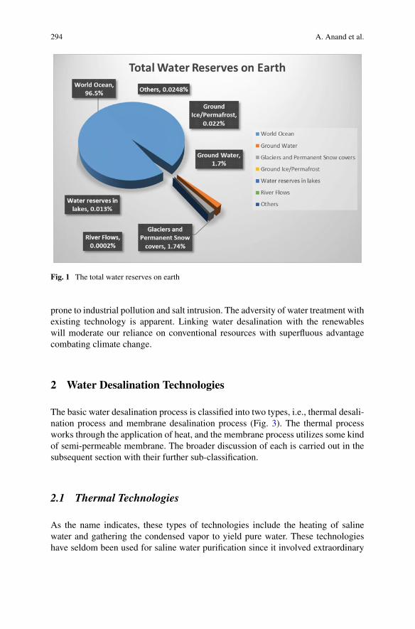
294 A. Anand et al.
Fig. 1 The total water reserves on earth
prone to industrial pollution and salt intrusion. The adversity of water treatment withexisting technology is apparent. Linking water desalination with the renewableswill moderate our reliance on conventional resources with superfluous advantagecombating climate change.
2 Water Desalination Technologies
The basic water desalination process is classified into two types, i.e., thermal desali-nation process and membrane desalination process (Fig. 3). The thermal processworks through the application of heat, and the membrane process utilizes some kindof semi-permeable membrane. The broader discussion of each is carried out in thesubsequent section with their further sub-classification.
2.1 Thermal Technologies
As the name indicates, these types of technologies include the heating of salinewater and gathering the condensed vapor to yield pure water. These technologieshave seldom been used for saline water purification since it involved extraordinary
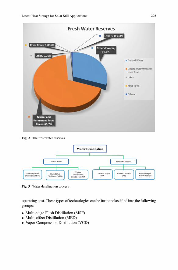
Latent Heat Storage for Solar Still Applications 295
Fig. 2 The freshwater reserves
Fig. 3 Water desalination process
operating cost. These types of technologies can be further classified into the followinggroups:
• Multi-stage Flash Distillation (MSF)• Multi-effect Distillation (MED)• Vapor Compression Distillation (VCD)
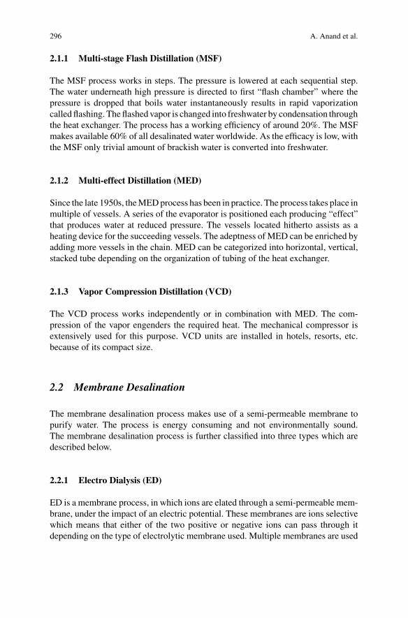
296 A. Anand et al.
2.1.1 Multi-stage Flash Distillation (MSF)
The MSF process works in steps. The pressure is lowered at each sequential step.The water underneath high pressure is directed to first “flash chamber” where thepressure is dropped that boils water instantaneously results in rapid vaporizationcalled flashing. Theflashed vapor is changed into freshwater by condensation throughthe heat exchanger. The process has a working efficiency of around 20%. The MSFmakes available 60% of all desalinated water worldwide. As the efficacy is low, withthe MSF only trivial amount of brackish water is converted into freshwater.
2.1.2 Multi-effect Distillation (MED)
Since the late 1950s, theMEDprocess has been in practice. The process takes place inmultiple of vessels. A series of the evaporator is positioned each producing “effect”that produces water at reduced pressure. The vessels located hitherto assists as aheating device for the succeeding vessels. The adeptness of MED can be enriched byadding more vessels in the chain. MED can be categorized into horizontal, vertical,stacked tube depending on the organization of tubing of the heat exchanger.
2.1.3 Vapor Compression Distillation (VCD)
The VCD process works independently or in combination with MED. The com-pression of the vapor engenders the required heat. The mechanical compressor isextensively used for this purpose. VCD units are installed in hotels, resorts, etc.because of its compact size.
2.2 Membrane Desalination
The membrane desalination process makes use of a semi-permeable membrane topurify water. The process is energy consuming and not environmentally sound.The membrane desalination process is further classified into three types which aredescribed below.
2.2.1 Electro Dialysis (ED)
ED is a membrane process, in which ions are elated through a semi-permeable mem-brane, under the impact of an electric potential. These membranes are ions selectivewhich means that either of the two positive or negative ions can pass through itdepending on the type of electrolytic membrane used. Multiple membranes are used
Latent Heat Storage for Solar Still Applications 297
in this process which ultimately removes positive or negative ions that flow throughit, and then, these ions are removed from wastewater.
2.2.2 Reverse Osmosis (RO)
In the process of osmosis, solvent molecule moves from the lower salt concentrationto the higher concentration through a semi-permeable membrane until the equilib-rium is reached. It is a spontaneous process. But the reversal of it, i.e., reverse osmosis,pressure equal or greater than osmotic pressure is applied on the higher salt concen-tration side so that the solvent molecules move to the lower concentration leavingbehind the salt residue. In this way, desalination is achieved.
2.2.3 Electro Dialysis Reversal (EDR)
In the Electro Dialysis Reversal process, we need to change the polarity of theelectrode at the continuous interval. EDR technology offers higher water recovery.It has the higher potential to prevent scaling and fouling arises out of the high saltconcentration of Calcium (Ca) and Magnesium (Mg). It is quite effective in treatingBarium (Ba) and Strontium (Sr) ions.
3 Solar Still
Solar still uses the direct energy of the sunlight to purify water. It is generally athermal desalination process. The technology is quite energy efficient as it requiresno additional energy inputs. Water is allowed to evaporate, and the vapor is thenallowed to condense which is then collected. The process is the same as we seeduring precipitation. The solar still is categorized into two types, i.e., active processand passive process and is shown in Fig. 4.
3.1 The Passive Solar Still
The passive still works in direct heat of the sunlight with no other additional source ofheat. The temperature achieved is relatively low, so the productivity is quite meagre.The basic design of the passive solar still is shown in Fig. 5.
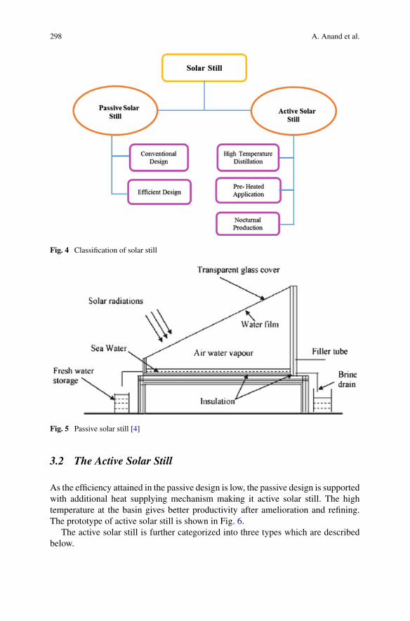
298 A. Anand et al.
Fig. 4 Classification of solar still
Fig. 5 Passive solar still [4]
3.2 The Active Solar Still
As the efficiency attained in the passive design is low, the passive design is supportedwith additional heat supplying mechanism making it active solar still. The hightemperature at the basin gives better productivity after amelioration and refining.The prototype of active solar still is shown in Fig. 6.
The active solar still is further categorized into three types which are describedbelow.
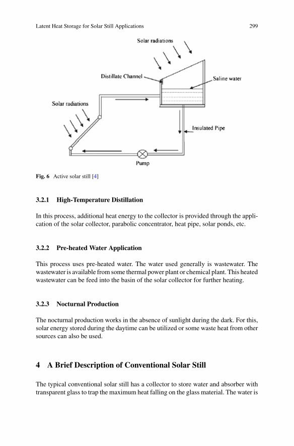
Latent Heat Storage for Solar Still Applications 299
Fig. 6 Active solar still [4]
3.2.1 High-Temperature Distillation
In this process, additional heat energy to the collector is provided through the appli-cation of the solar collector, parabolic concentrator, heat pipe, solar ponds, etc.
3.2.2 Pre-heated Water Application
This process uses pre-heated water. The water used generally is wastewater. Thewastewater is available from some thermal power plant or chemical plant. This heatedwastewater can be feed into the basin of the solar collector for further heating.
3.2.3 Nocturnal Production
The nocturnal production works in the absence of sunlight during the dark. For this,solar energy stored during the daytime can be utilized or some waste heat from othersources can also be used.
4 A Brief Description of Conventional Solar Still
The typical conventional solar still has a collector to store water and absorber withtransparent glass to trap the maximum heat falling on the glass material. The water is
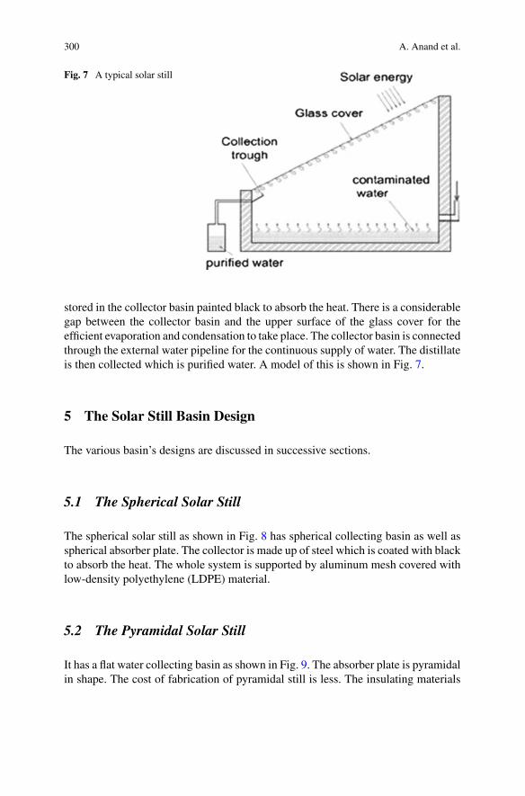
300 A. Anand et al.
Fig. 7 A typical solar still
stored in the collector basin painted black to absorb the heat. There is a considerablegap between the collector basin and the upper surface of the glass cover for theefficient evaporation and condensation to take place. The collector basin is connectedthrough the external water pipeline for the continuous supply of water. The distillateis then collected which is purified water. A model of this is shown in Fig. 7.
5 The Solar Still Basin Design
The various basin’s designs are discussed in successive sections.
5.1 The Spherical Solar Still
The spherical solar still as shown in Fig. 8 has spherical collecting basin as well asspherical absorber plate. The collector is made up of steel which is coated with blackto absorb the heat. The whole system is supported by aluminum mesh covered withlow-density polyethylene (LDPE) material.
5.2 The Pyramidal Solar Still
It has a flat water collecting basin as shown in Fig. 9. The absorber plate is pyramidalin shape. The cost of fabrication of pyramidal still is less. The insulating materials
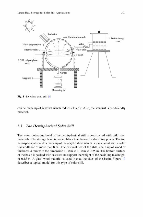
Latent Heat Storage for Solar Still Applications 301
Fig. 8 Spherical solar still [4]
can be made up of sawdust which reduces its cost. Also, the sawdust is eco-friendlymaterial.
5.3 The Hemispherical Solar Still
The water collecting bowl of the hemispherical still is constructed with mild steelmaterials. The storage bowl is coated black to enhance its absorbing power. The tophemispherical shield is made up of the acrylic sheet which is transparent with a solartransmittance of more than 80%. The external box of the still is built up of wood ofthickness 4 mm with the dimension 1.10 m × 1.10 m × 0.25 m. The bottom surfaceof the basin is packed with sawdust (to support the weight of the basin) up to a heightof 0.15 m. A glass wool material is used to coat the sides of the basin. Figure 10describes a typical model for this type of solar still.
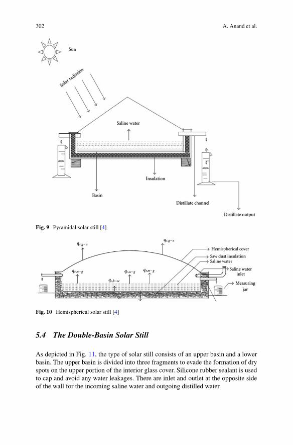
302 A. Anand et al.
Fig. 9 Pyramidal solar still [4]
Fig. 10 Hemispherical solar still [4]
5.4 The Double-Basin Solar Still
As depicted in Fig. 11, the type of solar still consists of an upper basin and a lowerbasin. The upper basin is divided into three fragments to evade the formation of dryspots on the upper portion of the interior glass cover. Silicone rubber sealant is usedto cap and avoid any water leakages. There are inlet and outlet at the opposite sideof the wall for the incoming saline water and outgoing distilled water.
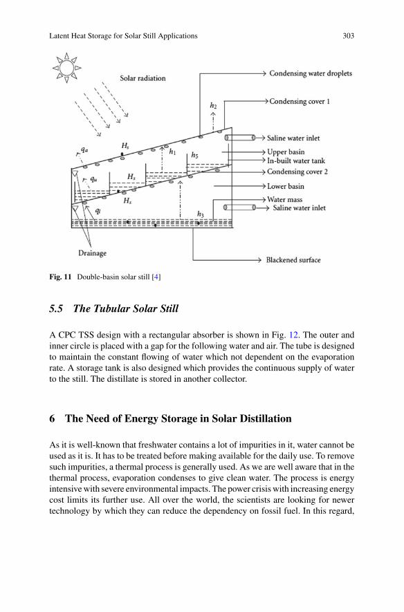
Latent Heat Storage for Solar Still Applications 303
Fig. 11 Double-basin solar still [4]
5.5 The Tubular Solar Still
A CPC TSS design with a rectangular absorber is shown in Fig. 12. The outer andinner circle is placed with a gap for the following water and air. The tube is designedto maintain the constant flowing of water which not dependent on the evaporationrate. A storage tank is also designed which provides the continuous supply of waterto the still. The distillate is stored in another collector.
6 The Need of Energy Storage in Solar Distillation
As it is well-known that freshwater contains a lot of impurities in it, water cannot beused as it is. It has to be treated before making available for the daily use. To removesuch impurities, a thermal process is generally used. As we are well aware that in thethermal process, evaporation condenses to give clean water. The process is energyintensivewith severe environmental impacts. The power crisiswith increasing energycost limits its further use. All over the world, the scientists are looking for newertechnology by which they can reduce the dependency on fossil fuel. In this regard,
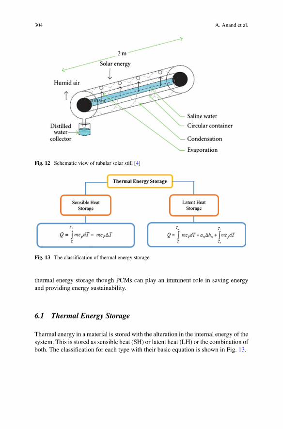
304 A. Anand et al.
Fig. 12 Schematic view of tubular solar still [4]
Fig. 13 The classification of thermal energy storage
thermal energy storage though PCMs can play an imminent role in saving energyand providing energy sustainability.
6.1 Thermal Energy Storage
Thermal energy in a material is stored with the alteration in the internal energy of thesystem. This is stored as sensible heat (SH) or latent heat (LH) or the combination ofboth. The classification for each type with their basic equation is shown in Fig. 13.
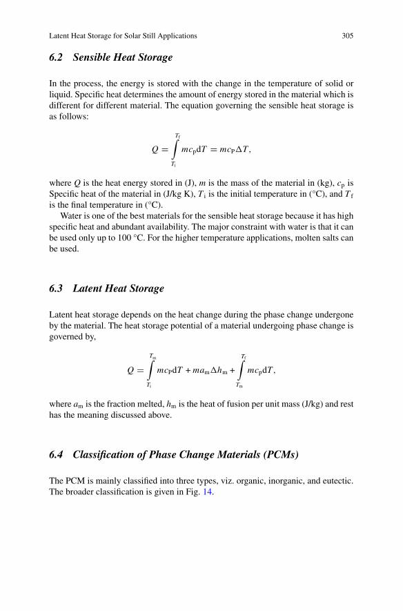
Latent Heat Storage for Solar Still Applications 305
6.2 Sensible Heat Storage
In the process, the energy is stored with the change in the temperature of solid orliquid. Specific heat determines the amount of energy stored in the material which isdifferent for different material. The equation governing the sensible heat storage isas follows:
Q �Tf∫
Ti
mcpdT � mcP�T,
where Q is the heat energy stored in (J), m is the mass of the material in (kg), cp isSpecific heat of the material in (J/kg K), T i is the initial temperature in (°C), and T f
is the final temperature in (°C).Water is one of the best materials for the sensible heat storage because it has high
specific heat and abundant availability. The major constraint with water is that it canbe used only up to 100 °C. For the higher temperature applications, molten salts canbe used.
6.3 Latent Heat Storage
Latent heat storage depends on the heat change during the phase change undergoneby the material. The heat storage potential of a material undergoing phase change isgoverned by,
Q �Tm∫
Ti
mcPdT + mam�hm +
Tf∫
Tm
mcpdT,
where am is the fraction melted, hm is the heat of fusion per unit mass (J/kg) and resthas the meaning discussed above.
6.4 Classification of Phase Change Materials (PCMs)
The PCM is mainly classified into three types, viz. organic, inorganic, and eutectic.The broader classification is given in Fig. 14.
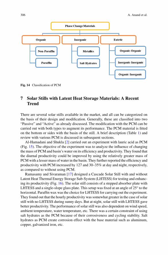
306 A. Anand et al.
Fig. 14 Classification of PCM
7 Solar Stills with Latent Heat Storage Materials: A RecentTrend
There are several solar stills available in the market, and all can be categorized onthe basis of their design and modification. Generally, these are classified into two“Passive” and “Active” as already discussed. The modification with the PCM can becarried out with both types to augment its performance. The PCM material is fittedon the bottom or sides with the basin of the still. A brief description (Table 1) andreview with various PCM is discussed in subsequent sections.
Al-Hamadani and Shukla [2] carried out an experiment with lauric acid as PCM(Fig. 15). The objective of the experiment was to analyze the influence of changingthemass of PCM and basin’s water on its efficiency and productivity. They found thatthe diurnal productivity could be improved by using the relatively greater mass ofPCMwith a lesser mass of water in the basin. They further reported the efficiency andproductivity with PCM increased by 127 and 30–35% at day and night, respectively,as compared to without using PCM.
Ramasamy and Sivaraman [17] designed a Cascade Solar Still with and withoutLatent Heat Thermal Energy Storage Sub-System (LHTESS) for testing and enhanc-ing its productivity (Fig. 16). The solar still consists of a stepped absorber plate withLHTESS and a single-slope glass plate. This setup was fixed at an angle of 25° to thehorizontal. Paraffin wax was the choice for LHTESS for carrying out the experiment.They found out that the hourly productivity was somewhat greater in the case of solarstill with no LHTESS during sunny days. But at night, solar still with LHTESS gavebetter productivity. The performance of solar still was also dependent on wind speed,ambient temperature, water temperature, etc. There was a certain constraint of usingsalt hydrates as the PCM because of their corrosiveness and cycling stability. Salthydrates as PCM create corrosion effect with the base material such as aluminum,copper, galvanized iron, etc.
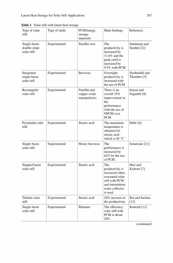
Latent Heat Storage for Solar Still Applications 307
Table 1 Solar still with latent heat storage
Type of solarstill
Type of study PCM/energystoragematerials
Main findings Reference
Single-basindouble-slopesolar still
Experimental Paraffin wax Theproductivity isincreased by11.6% and thepeak yield isincreased by9.5% with PCM
Sundaram andSenthil [22]
Integratedsingle-basinsolar still
Experimental Beeswax Overnightproductivity isincreased withthe use of PCM
Deshmukh andThombre [5]
Rectangularsolar still
Experimental Paraffin andcopper oxidenanoparticles
There is anoverall 35%improvement intheperformancewith the use ofNPCM overPCM
Iniyan andSuganthi [9]
Pyramidal solarstill
Experimental Stearic acid The maximumtemperature isobtained forstearic acidwhich is 65 °C
Dube [6]
Single-basinsolar still
Experimental Honey beeswax Theperformance isincreased by62% by the useof PCM
Sonawane [21]
Stepped basinsolar still
Experimental Stearic acid Theproductivity isincreased whenevacuated solarstill with PCMand intermittentwater collectoris used
Hari andKishore [7]
Tubular solarstill
Experimental Stearic acid 20% increase inthe productivity
Rai and Sachan[15]
Single-basinsolar still
Experimental Bitumen The efficiencysolar still withPCM is about20%
Kantesh [11]
(continued)
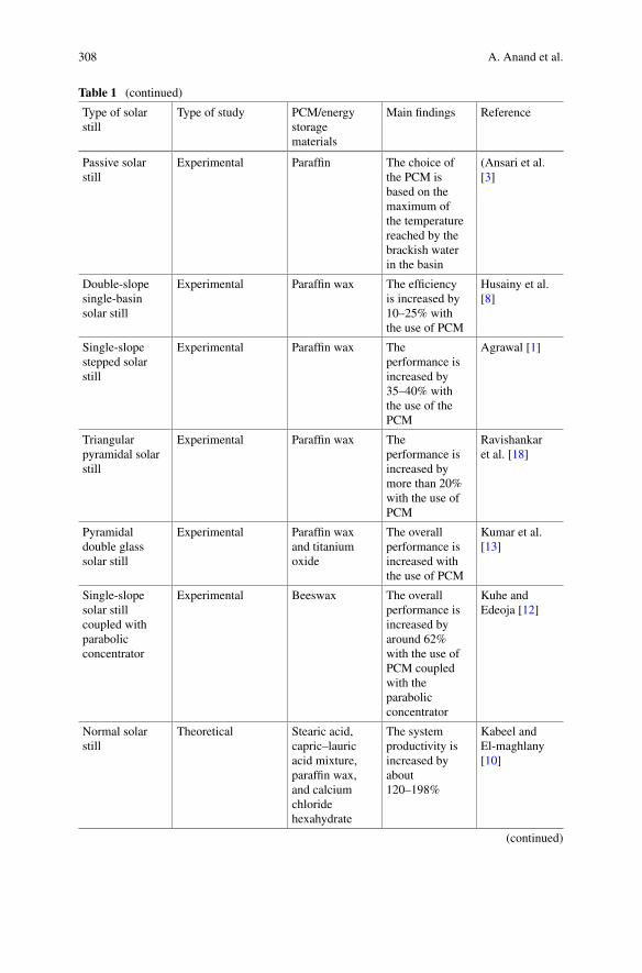
308 A. Anand et al.
Table 1 (continued)
Type of solarstill
Type of study PCM/energystoragematerials
Main findings Reference
Passive solarstill
Experimental Paraffin The choice ofthe PCM isbased on themaximum ofthe temperaturereached by thebrackish waterin the basin
(Ansari et al.[3]
Double-slopesingle-basinsolar still
Experimental Paraffin wax The efficiencyis increased by10–25% withthe use of PCM
Husainy et al.[8]
Single-slopestepped solarstill
Experimental Paraffin wax Theperformance isincreased by35–40% withthe use of thePCM
Agrawal [1]
Triangularpyramidal solarstill
Experimental Paraffin wax Theperformance isincreased bymore than 20%with the use ofPCM
Ravishankaret al. [18]
Pyramidaldouble glasssolar still
Experimental Paraffin waxand titaniumoxide
The overallperformance isincreased withthe use of PCM
Kumar et al.[13]
Single-slopesolar stillcoupled withparabolicconcentrator
Experimental Beeswax The overallperformance isincreased byaround 62%with the use ofPCM coupledwith theparabolicconcentrator
Kuhe andEdeoja [12]
Normal solarstill
Theoretical Stearic acid,capric–lauricacid mixture,paraffin wax,and calciumchloridehexahydrate
The systemproductivity isincreased byabout120–198%
Kabeel andEl-maghlany[10]
(continued)
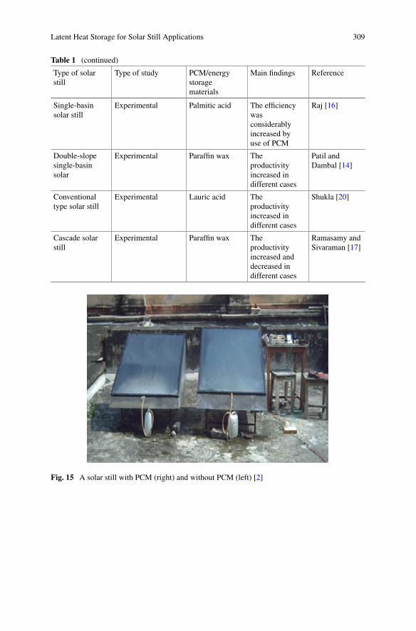
Latent Heat Storage for Solar Still Applications 309
Table 1 (continued)
Type of solarstill
Type of study PCM/energystoragematerials
Main findings Reference
Single-basinsolar still
Experimental Palmitic acid The efficiencywasconsiderablyincreased byuse of PCM
Raj [16]
Double-slopesingle-basinsolar
Experimental Paraffin wax Theproductivityincreased indifferent cases
Patil andDambal [14]
Conventionaltype solar still
Experimental Lauric acid Theproductivityincreased indifferent cases
Shukla [20]
Cascade solarstill
Experimental Paraffin wax Theproductivityincreased anddecreased indifferent cases
Ramasamy andSivaraman [17]
Fig. 15 A solar still with PCM (right) and without PCM (left) [2]
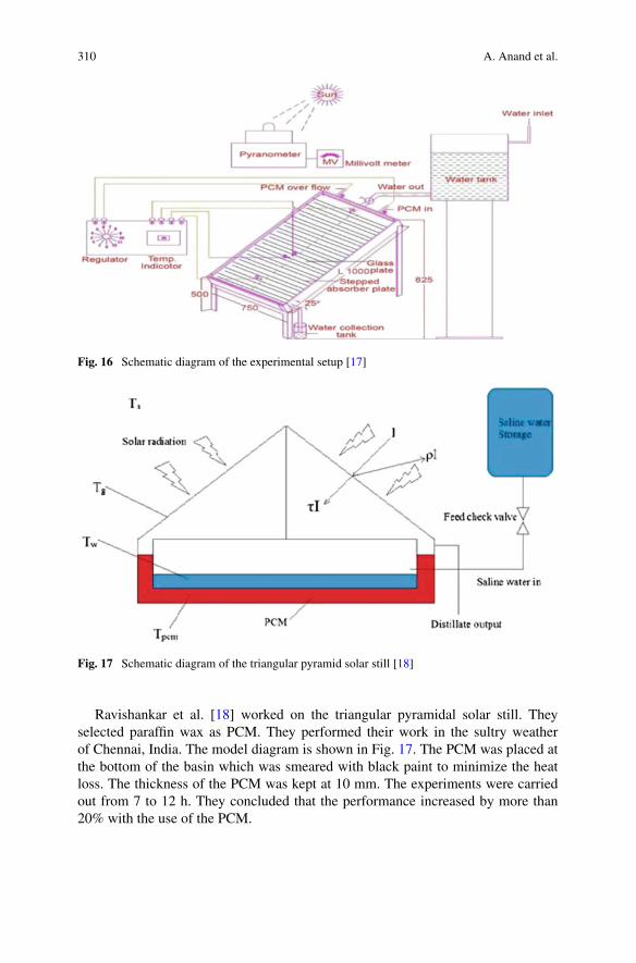
310 A. Anand et al.
Fig. 16 Schematic diagram of the experimental setup [17]
Fig. 17 Schematic diagram of the triangular pyramid solar still [18]
Ravishankar et al. [18] worked on the triangular pyramidal solar still. Theyselected paraffin wax as PCM. They performed their work in the sultry weatherof Chennai, India. The model diagram is shown in Fig. 17. The PCM was placed atthe bottom of the basin which was smeared with black paint to minimize the heatloss. The thickness of the PCM was kept at 10 mm. The experiments were carriedout from 7 to 12 h. They concluded that the performance increased by more than20% with the use of the PCM.
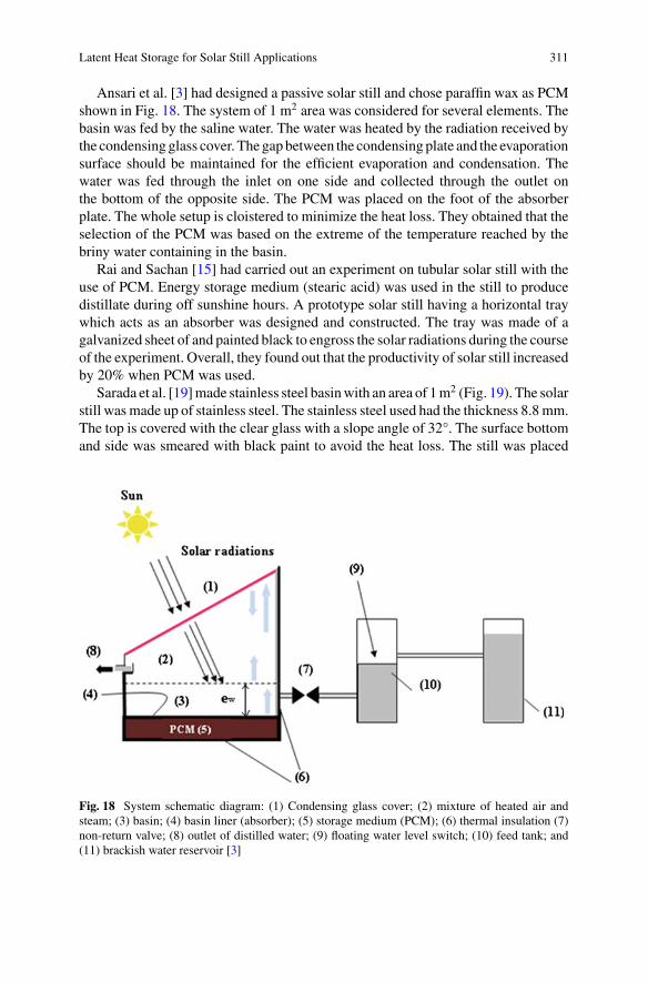
Latent Heat Storage for Solar Still Applications 311
Ansari et al. [3] had designed a passive solar still and chose paraffin wax as PCMshown in Fig. 18. The system of 1 m2 area was considered for several elements. Thebasin was fed by the saline water. The water was heated by the radiation received bythe condensing glass cover. The gapbetween the condensing plate and the evaporationsurface should be maintained for the efficient evaporation and condensation. Thewater was fed through the inlet on one side and collected through the outlet onthe bottom of the opposite side. The PCM was placed on the foot of the absorberplate. The whole setup is cloistered to minimize the heat loss. They obtained that theselection of the PCM was based on the extreme of the temperature reached by thebriny water containing in the basin.
Rai and Sachan [15] had carried out an experiment on tubular solar still with theuse of PCM. Energy storage medium (stearic acid) was used in the still to producedistillate during off sunshine hours. A prototype solar still having a horizontal traywhich acts as an absorber was designed and constructed. The tray was made of agalvanized sheet of and painted black to engross the solar radiations during the courseof the experiment. Overall, they found out that the productivity of solar still increasedby 20% when PCM was used.
Sarada et al. [19]made stainless steel basinwith an area of 1m2 (Fig. 19). The solarstill was made up of stainless steel. The stainless steel used had the thickness 8.8 mm.The top is covered with the clear glass with a slope angle of 32°. The surface bottomand side was smeared with black paint to avoid the heat loss. The still was placed
Fig. 18 System schematic diagram: (1) Condensing glass cover; (2) mixture of heated air andsteam; (3) basin; (4) basin liner (absorber); (5) storage medium (PCM); (6) thermal insulation (7)non-return valve; (8) outlet of distilled water; (9) floating water level switch; (10) feed tank; and(11) brackish water reservoir [3]
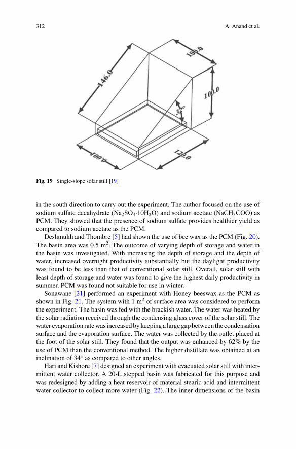
312 A. Anand et al.
Fig. 19 Single-slope solar still [19]
in the south direction to carry out the experiment. The author focused on the use ofsodium sulfate decahydrate (Na2SO4·10H2O) and sodium acetate (NaCH3COO) asPCM. They showed that the presence of sodium sulfate provides healthier yield ascompared to sodium acetate as the PCM.
Deshmukh and Thombre [5] had shown the use of bee wax as the PCM (Fig. 20).The basin area was 0.5 m2. The outcome of varying depth of storage and water inthe basin was investigated. With increasing the depth of storage and the depth ofwater, increased overnight productivity substantially but the daylight productivitywas found to be less than that of conventional solar still. Overall, solar still withleast depth of storage and water was found to give the highest daily productivity insummer. PCM was found not suitable for use in winter.
Sonawane [21] performed an experiment with Honey beeswax as the PCM asshown in Fig. 21. The system with 1 m2 of surface area was considered to performthe experiment. The basin was fed with the brackish water. The water was heated bythe solar radiation received through the condensing glass cover of the solar still. Thewater evaporation ratewas increasedbykeeping a large gapbetween the condensationsurface and the evaporation surface. The water was collected by the outlet placed atthe foot of the solar still. They found that the output was enhanced by 62% by theuse of PCM than the conventional method. The higher distillate was obtained at aninclination of 34° as compared to other angles.
Hari and Kishore [7] designed an experiment with evacuated solar still with inter-mittent water collector. A 20-L stepped basin was fabricated for this purpose andwas redesigned by adding a heat reservoir of material stearic acid and intermittentwater collector to collect more water (Fig. 22). The inner dimensions of the basin
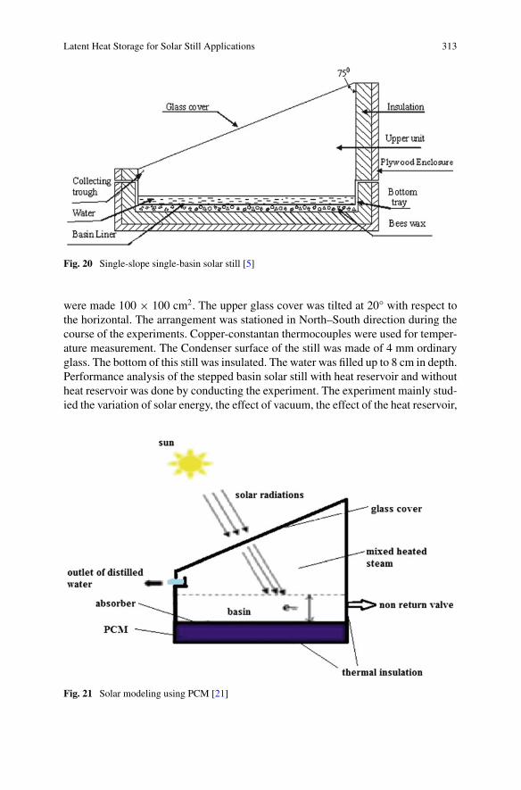
Latent Heat Storage for Solar Still Applications 313
Fig. 20 Single-slope single-basin solar still [5]
were made 100 × 100 cm2. The upper glass cover was tilted at 20° with respect tothe horizontal. The arrangement was stationed in North–South direction during thecourse of the experiments. Copper-constantan thermocouples were used for temper-ature measurement. The Condenser surface of the still was made of 4 mm ordinaryglass. The bottom of this still was insulated. The water was filled up to 8 cm in depth.Performance analysis of the stepped basin solar still with heat reservoir and withoutheat reservoir was done by conducting the experiment. The experiment mainly stud-ied the variation of solar energy, the effect of vacuum, the effect of the heat reservoir,
Fig. 21 Solar modeling using PCM [21]
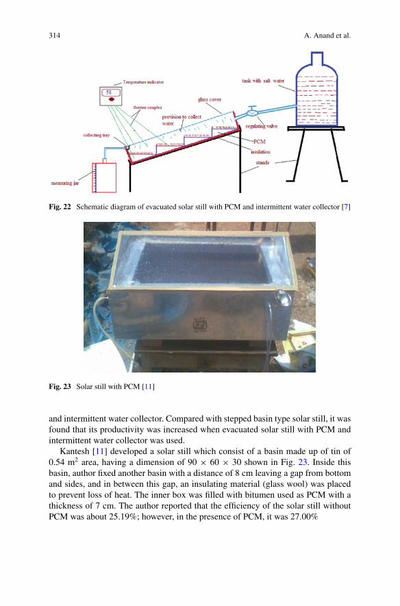
314 A. Anand et al.
Fig. 22 Schematic diagram of evacuated solar still with PCM and intermittent water collector [7]
Fig. 23 Solar still with PCM [11]
and intermittent water collector. Compared with stepped basin type solar still, it wasfound that its productivity was increased when evacuated solar still with PCM andintermittent water collector was used.
Kantesh [11] developed a solar still which consist of a basin made up of tin of0.54 m2 area, having a dimension of 90 × 60 × 30 shown in Fig. 23. Inside thisbasin, author fixed another basin with a distance of 8 cm leaving a gap from bottomand sides, and in between this gap, an insulating material (glass wool) was placedto prevent loss of heat. The inner box was filled with bitumen used as PCM with athickness of 7 cm. The author reported that the efficiency of the solar still withoutPCM was about 25.19%; however, in the presence of PCM, it was 27.00%
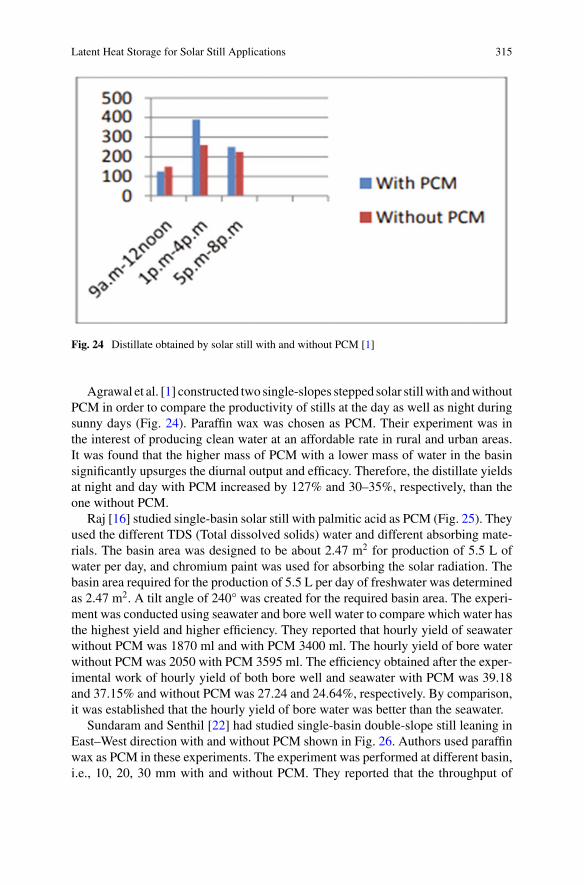
Latent Heat Storage for Solar Still Applications 315
Fig. 24 Distillate obtained by solar still with and without PCM [1]
Agrawal et al. [1] constructed two single-slopes stepped solar stillwith andwithoutPCM in order to compare the productivity of stills at the day as well as night duringsunny days (Fig. 24). Paraffin wax was chosen as PCM. Their experiment was inthe interest of producing clean water at an affordable rate in rural and urban areas.It was found that the higher mass of PCM with a lower mass of water in the basinsignificantly upsurges the diurnal output and efficacy. Therefore, the distillate yieldsat night and day with PCM increased by 127% and 30–35%, respectively, than theone without PCM.
Raj [16] studied single-basin solar still with palmitic acid as PCM (Fig. 25). Theyused the different TDS (Total dissolved solids) water and different absorbing mate-rials. The basin area was designed to be about 2.47 m2 for production of 5.5 L ofwater per day, and chromium paint was used for absorbing the solar radiation. Thebasin area required for the production of 5.5 L per day of freshwater was determinedas 2.47 m2. A tilt angle of 240° was created for the required basin area. The experi-ment was conducted using seawater and bore well water to compare which water hasthe highest yield and higher efficiency. They reported that hourly yield of seawaterwithout PCM was 1870 ml and with PCM 3400 ml. The hourly yield of bore waterwithout PCM was 2050 with PCM 3595 ml. The efficiency obtained after the exper-imental work of hourly yield of both bore well and seawater with PCM was 39.18and 37.15% and without PCM was 27.24 and 24.64%, respectively. By comparison,it was established that the hourly yield of bore water was better than the seawater.
Sundaram and Senthil [22] had studied single-basin double-slope still leaning inEast–West direction with and without PCM shown in Fig. 26. Authors used paraffinwax as PCM in these experiments. The experiment was performed at different basin,i.e., 10, 20, 30 mm with and without PCM. They reported that the throughput of
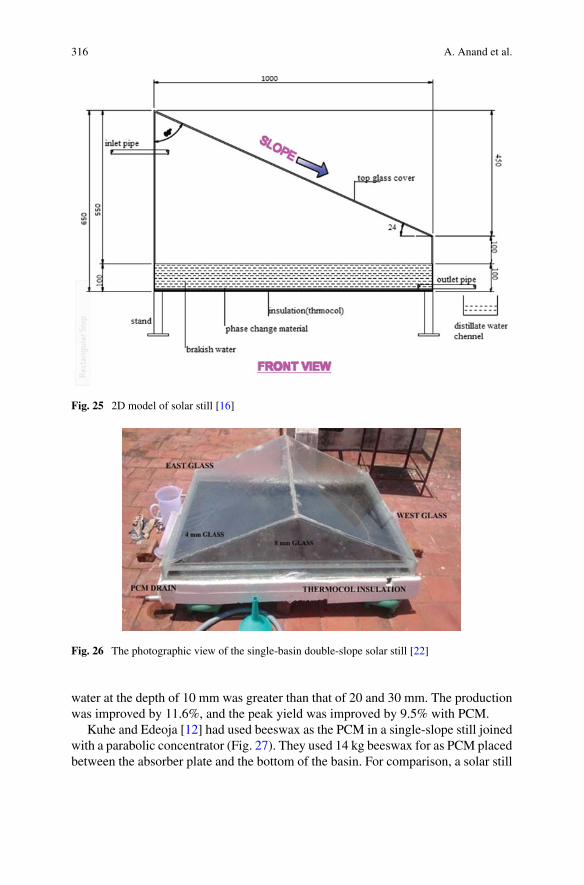
316 A. Anand et al.
Fig. 25 2D model of solar still [16]
Fig. 26 The photographic view of the single-basin double-slope solar still [22]
water at the depth of 10 mm was greater than that of 20 and 30 mm. The productionwas improved by 11.6%, and the peak yield was improved by 9.5% with PCM.
Kuhe and Edeoja [12] had used beeswax as the PCM in a single-slope still joinedwith a parabolic concentrator (Fig. 27). They used 14 kg beeswax for as PCM placedbetween the absorber plate and the bottom of the basin. For comparison, a solar still
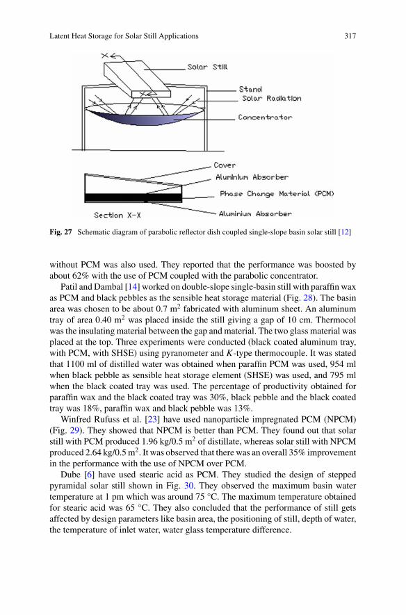
Latent Heat Storage for Solar Still Applications 317
Fig. 27 Schematic diagram of parabolic reflector dish coupled single-slope basin solar still [12]
without PCM was also used. They reported that the performance was boosted byabout 62% with the use of PCM coupled with the parabolic concentrator.
Patil and Dambal [14] worked on double-slope single-basin still with paraffin waxas PCM and black pebbles as the sensible heat storage material (Fig. 28). The basinarea was chosen to be about 0.7 m2 fabricated with aluminum sheet. An aluminumtray of area 0.40 m2 was placed inside the still giving a gap of 10 cm. Thermocolwas the insulating material between the gap and material. The two glass material wasplaced at the top. Three experiments were conducted (black coated aluminum tray,with PCM, with SHSE) using pyranometer and K-type thermocouple. It was statedthat 1100 ml of distilled water was obtained when paraffin PCM was used, 954 mlwhen black pebble as sensible heat storage element (SHSE) was used, and 795 mlwhen the black coated tray was used. The percentage of productivity obtained forparaffin wax and the black coated tray was 30%, black pebble and the black coatedtray was 18%, paraffin wax and black pebble was 13%.
Winfred Rufuss et al. [23] have used nanoparticle impregnated PCM (NPCM)(Fig. 29). They showed that NPCM is better than PCM. They found out that solarstill with PCM produced 1.96 kg/0.5 m2 of distillate, whereas solar still with NPCMproduced 2.64 kg/0.5m2. It was observed that there was an overall 35% improvementin the performance with the use of NPCM over PCM.
Dube [6] have used stearic acid as PCM. They studied the design of steppedpyramidal solar still shown in Fig. 30. They observed the maximum basin watertemperature at 1 pm which was around 75 °C. The maximum temperature obtainedfor stearic acid was 65 °C. They also concluded that the performance of still getsaffected by design parameters like basin area, the positioning of still, depth of water,the temperature of inlet water, water glass temperature difference.
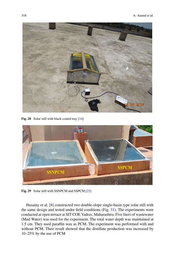
318 A. Anand et al.
Fig. 28 Solar still with black coated tray [14]
Fig. 29 Solar still with SSNPCM and SSPCM [23]
Husainy et al. [8] constructed two double-slope single-basin type solar still withthe same design and tested under field conditions (Fig. 31). The experiments wereconducted at open terrace at SIT COEYadrav, Maharashtra. Five liters of wastewater(Mud Water) was used for the experiment. The total water depth was maintained at1.5 cm. They used paraffin wax as PCM. The experiment was performed with andwithout PCM. Their result showed that the distillate production was increased by10–25% by the use of PCM
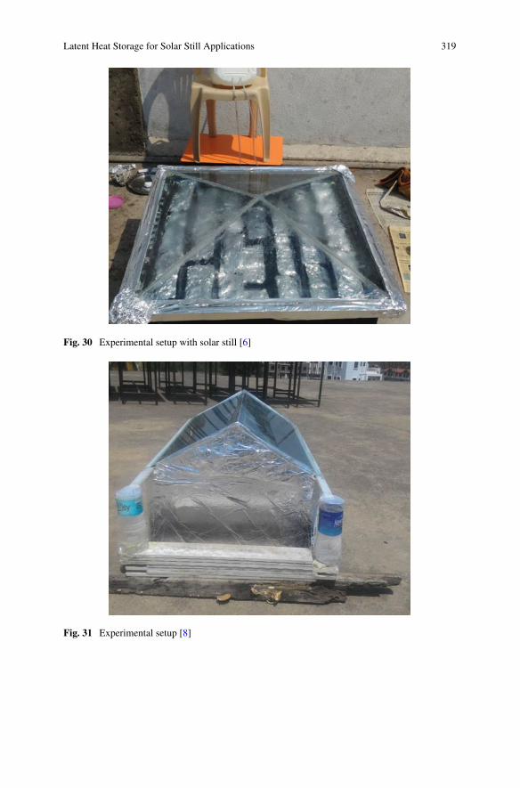
Latent Heat Storage for Solar Still Applications 319
Fig. 30 Experimental setup with solar still [6]
Fig. 31 Experimental setup [8]
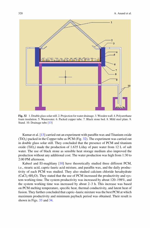
320 A. Anand et al.
Fig. 32 1.Double glass solar still. 2. Projection forwater drainage. 3.Woodenwall. 4. Polyurethanefoam insulation. 5. Wastewater. 6. Packed copper tube. 7. Black stone bed. 8. Mild steel plate. 9.Stand. 10. Drainage tube [13]
Kumar et al. [13] carried out an experiment with paraffin wax and Titanium oxide(TiO2) packed in the Copper tube as PCM (Fig. 32). The experiment was carried outin double glass solar still. They concluded that the presence of PCM and titaniumoxide (TiO2) made the production of 1.635 L/day of pure water from 12 L of saltwater. The use of black stone as sensible heat storage medium also improved theproduction without any additional cost. The water production was high from 1:30 to2:00 PM afternoon.
Kabeel and El-maghlany [10] have theoretically studied three different PCM,i.e., stearic acid, capric-lauric acid mixture, and paraffin wax, and the daily produc-tivity of each PCM was studied. They also studied calcium chloride hexahydrate(CaCl2·6H2O). They stated that the use of PCM increased the productivity and sys-tem working time. The system productivity was increased by about 120–198%, andthe system working time was increased by about 2–3 h. This increase was basedon PCM melting temperature, specific heat, thermal conductivity, and latent heat offusion. They further concluded that capric–lauric mixture was the best PCM at whichmaximum productivity and minimum payback period was obtained. Their result isshown in Figs. 33 and 34.
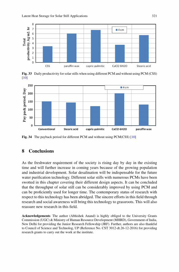
Latent Heat Storage for Solar Still Applications 321
Fig. 33 Daily productivity for solar stills when using different PCM and without using PCM (CSS)[10]
Fig. 34 The payback period for different PCM and without using PCM(CSS) [10]
8 Conclusions
As the freshwater requirement of the society is rising day by day in the existingtime and will further increase in coming years because of the growing populationand industrial development. Solar desalination will be indispensable for the futurewater purification technology. Different solar stills with numerous PCMs have beenswotted in this chapter covering their different design aspects. It can be concludedthat the throughput of solar still can be considerably improved by using PCM andcan be proficiently used for longer time. The contemporary status of research withrespect to this technology has been abridged. The sincere efforts in this field throughresearch and social awareness will bring this technology to grassroots. This will alsoreassure new research in this field.
Acknowledgements The author (Abhishek Anand) is highly obliged to the University GrantsCommission (UGC) &Ministry of Human Resource Development (MHRD), Government of India,New Delhi for providing the Junior Research Fellowship (JRF). Further, authors are also thankfulto Council of Science and Technolog, UP (Reference No. CST 3012-dt.26-12-2016) for providingresearch grants to carry out the work at the institute.
322 A. Anand et al.
References
1. Agrawal SS (2015) Distillation of water-using solar energy with phase change materials. Int JEng Res Appl (IJERA) 133–138
2. Al-Hamadani AAF, Shukla SK (2012) Water distillation using solar energy system with lauricacid as storage medium. Int J Energy Eng 1:1–8. https://doi.org/10.5923/j.ijee.20110101.01
3. Ansari O, Asbik M, Bah A, Arbaoui A, Khmou A (2013) Desalination of the brackish waterusing a passive solar still with a heat energy storage system. Desalination 324:10–20. https://doi.org/10.1016/j.desal.2013.05.017
4. Arunkumar T, Vinothkumar K, Ahsan A, Jayaprakash R, Kumar S (2012) Experimental studyon various solar still designs. ISRN Renew Energy 2012:1–10. https://doi.org/10.5402/2012/569381
5. Deshmukh HS, Thombre SB (2015) Experimental study of an integrated single basin solar stillwith bees wax as a passive storage material. Int J Therm Technol 5:226–231
6. Dube MK (2017) A study of performance of solar still with stearic acid as PCM. J Res 03:5–87. Hari B, Kishore J (2015) Evacuated stepped basin solar still with PCM and intermittent water
collector. Int J Res Appl Sci Eng Technol 3:321–3308. Husainy ASN, Karangale OS, Shinde VY (2017) Experimental study of double slope solar
distillation with and without effect of latent thermal energy storage. Asian Rev Mech Eng6:15–18
9. Iniyan S, Suganthi L (2017) Nanoparticles enhanced phase change material (NPCM) as heatstorage in solar still application for productivity enhancement. Energy Procedia 141:45–49.https://doi.org/10.1016/j.egypro.2017.11.009
10. Kabeel AE, El-maghlany WM (2017) Theoretical performance comparison of solar still usingdifferent PCM. In: Twentieth international water technology conference, IWTC20, pp 18–20
11. Kantesh DC (2012) Design of solar still using Phase changing material as a storage medium.Int J Sci Eng Res 3:1–6
12. KuheA,EdeojaAO(2016)Distillate yield improvement using a parabolic dish reflector coupledsingle slope basin solar still with thermal energy storage using beeswax. Leonardo Electron JPract Technol 137–146
13. Kumar MR, Sridhar M, Kumar SM, Vasanth CV (2017) Experimental investigation of solarwater desalination with phase change material and TiO. Imperial J Interdisc Res (IJIR)2:1128–1134
14. Patil BK, Dambal S (2016) Design and experimental performance analysis of solar still usingphase changing materials and sensible heat elements. Int J Res Mech Eng Technol 6:144–149
15. RaiAK, SachanV (2015) Experimental study of a tubular solar still with phase changematerial.Int J Mech Eng Technol 6:42–46
16. Raj KPRP (2015) Performance test on solar still for various tds water and phase change mate-rials. Int J Innov Res Sci Eng Technol 4:451–461
17. Ramasamy S, Sivaraman B (2013) Heat transfer enhancement of solar still using phase changematerials (PCMs). Int J Eng Adv Technol 2:597–600
18. Ravishankar S, Nagarajan PK, Vijayakumar D, Jawahar MK (2013) Phase change materialon augmentation of fresh water production using pyramid solar still. Int J Renew Energy Dev2:115–120
19. Sarada SN, Bindu BH, Devi SRR, Gugulothu R (2014) Solar water distillation using twodifferent phase change materials. Appl Mech Mater 592–594:2409–2415. https://doi.org/10.4028/www.scientific.net/AMM.592-594.2409
20. Shukla SK (2011) Water distillation using solar energy system with lauric acid as storagemedium. Int J Energy Eng 1:1–8. https://doi.org/10.5923/j.ijee.20110101.01
21. Sonawane D (2015) Research paper on enhancing solar still productivity by optimizing angleof PCM embedded absorber surface. IJSTE Int J Sci Technol Eng 2:192–196
22. Sundaram P, Senthil R (2016) Productivity enhancement of solar desalination system usingparaffin wax. Int J Chem Sci 14:2339–2348

Latent Heat Storage for Solar Still Applications 323
23. Winfred Rufuss DD, Iniyan S, Suganthi L, Pa D (2017) Nanoparticles enhanced phase changematerial (NPCM) as heat storage in solar still application for productivity enhancement. EnergyProcedia 141:45–49. https://doi.org/10.1016/j.egypro.2017.11.009
Productivity Improvementsof Adsorption Desalination Systems
Ramy H. Mohammed and Ahmed A. Askalany
Abstract Addressing the water energy cooling environment nexus in an integratedand proactive way is an insistent motivation for research, development, and innova-tion. This combination is highly valued as renewable energy is used to drive plantsto produce electrical power, provide cooling or heating, and extract clean water.Such plants significantly reduce the greenhouse gases and air pollutant emissionsgenerated by combustion of fossil fuels. Adsorption-based desalination (AD) sys-tem has been proposed to produce both fresh/potable water and cooling effect forrural and remote coastal communities. The system is powered by low-grade heator solar energy. Desalination feature has been added to adsorption cooling systemto distinguish it and improve its performance. However, the performance of thishybrid system is still relatively low comparing to the other cooling and desalinationtechnologies. Accordingly, the AD systems are being evolved steadily over the pastdecades to enhance their performance. In this chapter, the working principle of theAD cycle is demonstrated, and the characteristics of the recommended working pairsare discussed. Productivity progress of different arrangements of AD plant in termsof specific daily water production (SDWP) is presented in chronological order. Theeffect of the operating conditions and the system cycle time on the system perfor-mance is shown. Predicting the technology performance is also exhibited. Until now,the cycle could produce a SDWP up to 25 kg/kg of adsorbent per day. Moreover, thiswork summarizes the improvement that has been achieved in the last decades andthe trend of this technology in the near future.
Keywords Adsorption-based desalination · Specific daily water production ·Operating conditions · Future technology
R. H. MohammedMechanical Power Engineering Dept, Zagazig University, Zagazig, Egypt
A. A. Askalany (B)Institute of Material Science, School of Engineering, University of Edinburgh, Edinburgh, UKe-mail: [email protected]
Mechanical Engineering Department, Faculty of Industrial Education, Sohag University, Sohag,Egypt
© Springer Nature Singapore Pte Ltd. 2019A. Kumar and O. Prakash (eds.), Solar Desalination Technology,Green Energy and Technology, https://doi.org/10.1007/978-981-13-6887-5_15
325
326 R. H. Mohammed and A. A. Askalany
1 Introduction
Fossil fuels are still one of the major sources of energy, where oil, coal, and naturalgas are the predominant fossil fuels consumed bymost developing and industrializednations. The rapid and huge rise in the cost of the fossil fuels is unavoidable inthe world market due to the growth of world population and economically fast-developing countries. In addition, greenhouse gases (carbon dioxide (CO2) of 82%,methane (CH4) of 10%, nitrous oxide (N2O) of 10%, and fluorinated gases of 3%)through burning fossil fuels intensify dramatically. In turn, the finite amount offossil fuels starts to minimize because the world population keep growing, and itwill not be affordable to produce the amount of power required by the world. Thissuccessively reveals that the price of the desalinated water from traditional thermalsystems [multiple effect distillation (MED), multistage flash (MSF), reverse osmosis(RO)] will steadily augment. Moreover, the expected desertification process in manytemperate regions, such as Southern Europe, South USA, and the MediterraneanSea area, will cause an additional boost in water requirement. So, using renewableenergy such as solar energy to product energy and freshwater will be more andmore economically viable in the near future and seems to be a compulsory choice.Nowadays, water, cooling, energy, and environment are tightly intertwined. As aresult, there is a motivation for research, development, and innovation to handle thewater energy cooling environment nexus in an integrated and proactive way. Thisintegration is highly valued as it reduces and limits greenhouse gases and air pollutantemissions generated by combustion of fossil fuels.
Desalination processes are categorized into two major techniques: a heat-drivenprocess (distillation) and electric power-driven process or in other words thermaland non-thermal technologies as categorized in Fig. 1. The heat-driven process is asolar distillation, multistage flashing (MSF), and multiple effect distillation (MED).The electric power-driven process includes mechanical vapor compression cycle,freezing, reverse osmosis, and electrodialysis. These desalination systems suffer fromhigh energy consumption, corrosion, and foulingbecause of the seawater evaporation.On the other hand, since the AD system has nomoving parts, it proposed to overcomethe deficiencies of the conventional desalination techniques.
Hybrid adsorption cooling and desalination cycles driven by renewable energyhave received much interest owing to its capability of producing freshwater withzero emissions as well as a cooling effect. This system is able to treat highly concen-trated feedwater, ranging from chemically laden waste to water seawater. Also, heatsources with a temperature of less than 100 °C can power this system. However, thistechnology suffers from low cooling power capacity and freshwater production. Thedistinguished features of the adsorption-based desalination cycles compared with theother desalination methods are [1, 11, 39, 40, 47, 19–21]:
(i) utilization of low-grade waste energy below 100°C or solar heat,(ii) no moving parts, which render low maintenance cost,(iii) employing environmental friendly working pairs such as silica gel/water,(iv) zero greenhouse gases emissions,
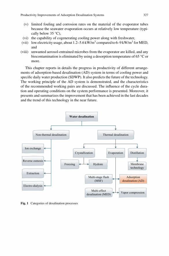
Productivity Improvements of Adsorption Desalination Systems 327
(v) limited fouling and corrosion rates on the material of the evaporator tubesbecause the seawater evaporation occurs at relatively low temperature (typi-cally below 35 °C),
(vi) the capability of cogenerating cooling power along with freshwater,(vii) lowelectricity usage, about 1.2–5.6 kW/m3 compared to 6–9kW/m3 forMED,
and(viii) unwanted aerosol-entrained microbes from the evaporator are killed, and any
biocontamination is eliminated by using a desorption temperature of 65 °C ormore.
This chapter reports in details the progress in productivity of different arrange-ments of adsorption-based desalination (AD) system in terms of cooling power andspecific daily water production (SDWP). It also predicts the future of the technology.The working principle of the AD system is demonstrated, and the characteristicsof the recommended working pairs are discussed. The influence of the cycle dura-tion and operating conditions on the system performance is presented. Moreover, itpresents and summarizes the improvement that has been achieved in the last decadesand the trend of this technology in the near future.
Water desalination
Non-thermal desalination Thermal desalination
Crystallization Evaporation Distillation
Membrane technology
HydrateFreezing
Adsorption desalination (AD)
Multi-effect desalination (MED) Vapor compression
Multi-stage flash (MSF)
Ion exchange
Reverse osmosis
Extraction
Electro-dialysis
Fig. 1 Categories of desalination processes
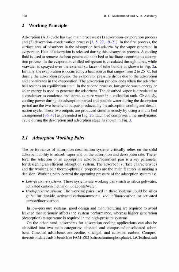
328 R. H. Mohammed and A. A. Askalany
2 Working Principle
Adsorption (AD) cycle has two main processes: (1) adsorption–evaporation processand (2) desorption–condensation process [3, 5, 27, 19–21]. In the first process, thesurface area of adsorbent in the adsorption bed adsorbs by the vapor generated inevaporator. Heat of adsorption is released during this adsorption process. A coolingfluid is used to remove the heat generated in the bed to facilitate a continuous adsorp-tion process. In the evaporator, chilled refrigerant is circulated through tubes, whileseawater is sprayed over the external surfaces of tube bundle as shown in Fig. 2a.Initially, the evaporation is occurred by a heat source that ranges from 2 to 25 °C, butduring the adsorption process, the evaporator pressure drops due to the adsorptionand contributes in the evaporation. The adsorption process ends when the adsorberbed reaches an equilibrium state. In the second process, low-grade waste energy orsolar energy is used to generate the adsorbent. The desorbed vapor is circulated toa condenser to condense and stored as pure water in a collection tank. Obviously,cooling power during the adsorption period and potable water during the desorptionperiod are the two beneficial outputs produced by the adsorption cooling and desali-nation cycle. These two outputs are produced simultaneously by using a multi-bedarrangement [36, 47] as presented in Fig. 2b. Each bed comprises a thermodynamiccycle during the desorption and adsorption stage as shown in Fig. 3.
2.1 Adsorption Working Pairs
The performance of adsorption desalination systems critically relies on the solidadsorbent ability to adsorb vapor and on the adsorption and desorption rate. There-fore, the selection of an appropriate adsorbate/adsorbent pair is a key parameterfor designing an efficient adsorption system. The adsorbent surface characteristicsand the working pair thermo-physical properties are the main features in making adecision. Working pairs control the operating pressure of the adsorption system as:
• Low-pressure systems: These systems use working pairs such as silica gel/water,activated carbon/methanol, or zeolite/water.
• High-pressure system: The working pairs used in these systems could be silicagel/sulfur dioxide, activated carbon/ammonia, zeolite/fluorocarbon, or activatedcarbon/fluorocarbon.
In low-pressure systems, good design and manufacturing are required to avoidleakage that seriously affects the system performance, whereas higher generation(desorption) temperature is required in the high-pressure systems.
On the other hand, adsorbents for adsorption cooling applications can also beclassified into two main categories: classical and composite/consolidated adsor-bent. Classical adsorbents are zeolite, silicagel, and activated carbon. Compos-ite/consolidated adsorbents likeFAM-Z02 (silicoaluminophosphate), LiCl/silica, salt
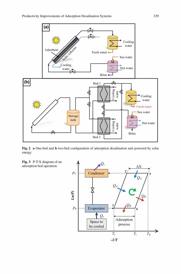
Productivity Improvements of Adsorption Desalination Systems 329
Cooling water
Cooling water
Brine
Fresh water
Hot water
Sea water
Adsorbent
(a)
(b)
Hot water
Storage tank
Bed 1
Bed 2Brine
Sea water
Cooling water
Fresh water
Coo
ling
wat
erC
oolin
g w
ater
Fig. 2 a One-bed and b two-bed configuration of adsorption desalination unit powered by solarenergy
Fig. 3 P-T-X diagram of anadsorption bed operation
Condenser
Adsorption process
Evaporator
ΔX
QA
Space to be cooled
-1/T
Ln(P)
PC
Pe1
4
23
QA
QR
QR
Qe
Qc
Tc Ti Td
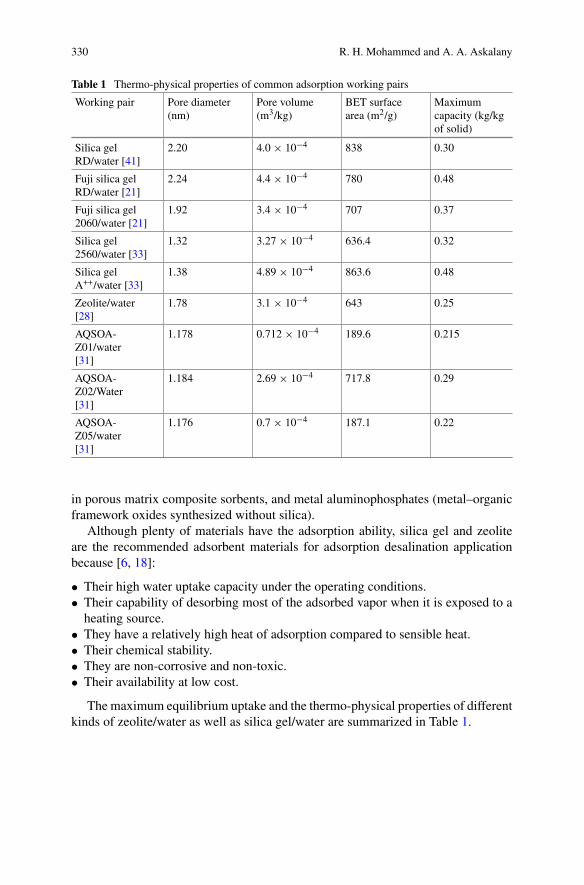
330 R. H. Mohammed and A. A. Askalany
Table 1 Thermo-physical properties of common adsorption working pairs
Working pair Pore diameter(nm)
Pore volume(m3/kg)
BET surfacearea (m2/g)
Maximumcapacity (kg/kgof solid)
Silica gelRD/water [41]
2.20 4.0 × 10⁻⁴ 838 0.30
Fuji silica gelRD/water [21]
2.24 4.4 × 10⁻⁴ 780 0.48
Fuji silica gel2060/water [21]
1.92 3.4 × 10⁻⁴ 707 0.37
Silica gel2560/water [33]
1.32 3.27 × 10⁻⁴ 636.4 0.32
Silica gelA++/water [33]
1.38 4.89 × 10⁻⁴ 863.6 0.48
Zeolite/water[28]
1.78 3.1 × 10⁻⁴ 643 0.25
AQSOA-Z01/water[31]
1.178 0.712 × 10⁻⁴ 189.6 0.215
AQSOA-Z02/Water[31]
1.184 2.69 × 10⁻⁴ 717.8 0.29
AQSOA-Z05/water[31]
1.176 0.7 × 10⁻⁴ 187.1 0.22
in porous matrix composite sorbents, and metal aluminophosphates (metal–organicframework oxides synthesized without silica).
Although plenty of materials have the adsorption ability, silica gel and zeoliteare the recommended adsorbent materials for adsorption desalination applicationbecause [6, 18]:
• Their high water uptake capacity under the operating conditions.• Their capability of desorbing most of the adsorbed vapor when it is exposed to aheating source.
• They have a relatively high heat of adsorption compared to sensible heat.• Their chemical stability.• They are non-corrosive and non-toxic.• Their availability at low cost.
The maximum equilibrium uptake and the thermo-physical properties of differentkinds of zeolite/water as well as silica gel/water are summarized in Table 1.
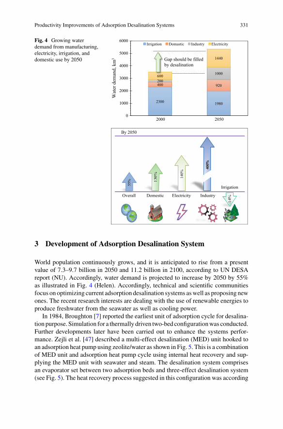
Productivity Improvements of Adsorption Desalination Systems 331
Fig. 4 Growing waterdemand from manufacturing,electricity, irrigation, anddomestic use by 2050
55%
140%
Overall
Irrigation
ElectricityDomestic Industry
400%
400%
By 2050
2300 1980
400 920200
1000600
1440
0
1000
2000
3000
4000
5000
6000
2000 2050W
ater
dem
and,
km
3
Irrigation Domastic Industry Electricity
Gap should be filled by desalination
3 Development of Adsorption Desalination System
World population continuously grows, and it is anticipated to rise from a presentvalue of 7.3–9.7 billion in 2050 and 11.2 billion in 2100, according to UN DESAreport (NU). Accordingly, water demand is projected to increase by 2050 by 55%as illustrated in Fig. 4 (Helen). Accordingly, technical and scientific communitiesfocus on optimizing current adsorption desalination systems aswell as proposing newones. The recent research interests are dealing with the use of renewable energies toproduce freshwater from the seawater as well as cooling power.
In 1984, Broughton [7] reported the earliest unit of adsorption cycle for desalina-tion purpose. Simulation for a thermally driven two-bed configurationwas conducted.Further developments later have been carried out to enhance the systems perfor-mance. Zejli et al. [47] described a multi-effect desalination (MED) unit hooked toan adsorption heat pump using zeolite/water as shown in Fig. 5. This is a combinationof MED unit and adsorption heat pump cycle using internal heat recovery and sup-plying the MED unit with seawater and steam. The desalination system comprisesan evaporator set between two adsorption beds and three-effect desalination system(see Fig. 5). The heat recovery process suggested in this configuration was according
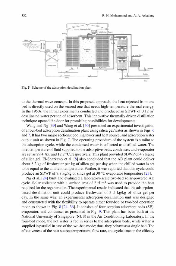
332 R. H. Mohammed and A. A. Askalany
Fig. 5 Scheme of the adsorption desalination plant
to the thermal wave concept. In this proposed approach, the heat rejected from onebed is directly used on the second one that needs high-temperature thermal energy.In the 1950s, the initial experiments conducted and produced an SDWP of 0.12 m3
desalinated water per ton of adsorbent. This innovative thermally driven distillationtechnique opened the door for promising possibilities for developments.
Wang and Ng [39] and Wang et al. [40] presented an experimental investigationof a four-bed adsorption desalination plant using silica gel/water as shown in Figs. 6and 7. It has two major sections: cooling tower and heat source, and adsorption wateroutput unit as shown in Fig. 7. The operating procedure of the system is similar tothe adsorption cycle, while the condensed water is collected as distilled water. Theinlet temperature of fluid supplied to the adsorptive beds, condenser, and evaporatorare set as 29.4, 85, and 12.2 °C, respectively. This plant provided SDWP of 4.7 kg/kgof silica gel. El-Sharkawy et al. [8] also concluded that the AD plant could deliverabout 8.2 kg of freshwater per kg of silica gel per day when the chilled water is setto be equal to the ambient temperature. Further, it was reported that this cycle couldproduce an SDWP of 7.8 kg/kg of silica gel at 30 °C evaporator temperature [23].
Ng et al. [24] built and evaluated a laboratory-scale two-bed solar-powered ADcycle. Solar collector with a surface area of 215 m2 was used to provide the heatrequired for the regeneration. The experimental results indicated that the adsorption-based desalination unit could produce freshwater of 3–5 kg/kg of silica gel perday. In the same way, an experimental adsorption desalination unit was designedand constructed with the flexibility to operate either four-bed or two-bed operationmode as shown in Fig. 8 [24, 36]. It consists of four sorption adsorbent beds (SE),evaporator, and condenser as presented in Fig. 9. This plant has been built at theNational University of Singapore (NUS) in the Air Conditioning Laboratory. In thefour-bed mode, the hot water is fed in series to the adsorption beds, while water issupplied in parallel in case of the two-bedmode; thus, they behave as a single bed. Theeffectiveness of the heat source temperature, flow rate, and cycle time on the efficacy
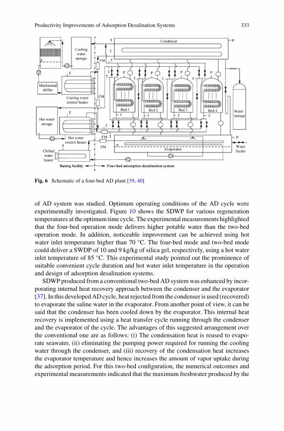
Productivity Improvements of Adsorption Desalination Systems 333
Fig. 6 Schematic of a four-bed AD plant [39, 40]
of AD system was studied. Optimum operating conditions of the AD cycle wereexperimentally investigated. Figure 10 shows the SDWP for various regenerationtemperatures at the optimum time cycle. The experimentalmeasurements highlightedthat the four-bed operation mode delivers higher potable water than the two-bedoperation mode. In addition, noticeable improvement can be achieved using hotwater inlet temperature higher than 70 °C. The four-bed mode and two-bed modecould deliver a SWDP of 10 and 9 kg/kg of silica gel, respectively, using a hot waterinlet temperature of 85 °C. This experimental study pointed out the prominence ofsuitable convenient cycle duration and hot water inlet temperature in the operationand design of adsorption desalination systems.
SDWP produced from a conventional two-bedAD systemwas enhanced by incor-porating internal heat recovery approach between the condenser and the evaporator[37]. In this developedADcycle, heat rejected from the condenser is used (recovered)to evaporate the saline water in the evaporator. From another point of view, it can besaid that the condenser has been cooled down by the evaporator. This internal heatrecovery is implemented using a heat transfer cycle running through the condenserand the evaporator of the cycle. The advantages of this suggested arrangement overthe conventional one are as follows: (i) The condensation heat is reused to evapo-rate seawater, (ii) eliminating the pumping power required for running the coolingwater through the condenser, and (iii) recovery of the condensation heat increasesthe evaporator temperature and hence increases the amount of vapor uptake duringthe adsorption period. For this two-bed configuration, the numerical outcomes andexperimental measurements indicated that the maximum freshwater produced by the
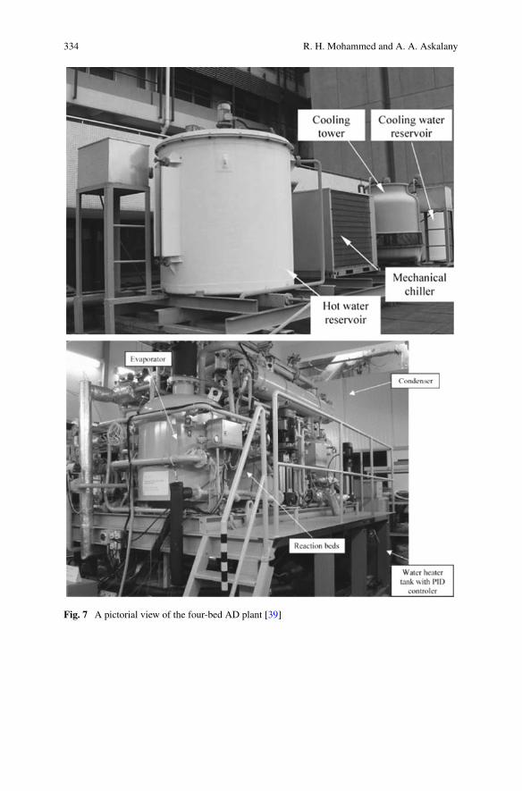
334 R. H. Mohammed and A. A. Askalany
Fig. 7 A pictorial view of the four-bed AD plant [39]
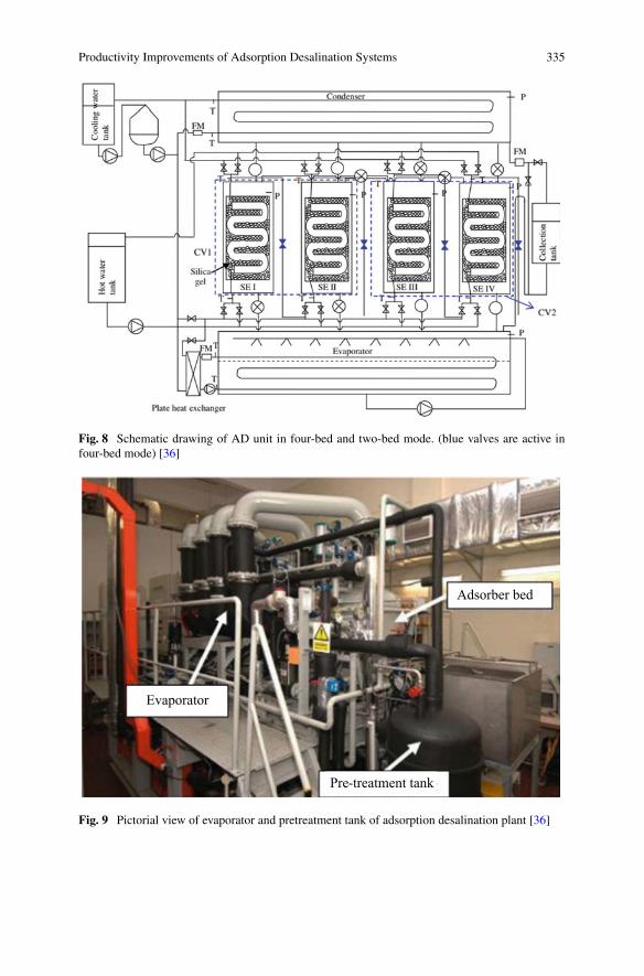
Productivity Improvements of Adsorption Desalination Systems 335
Fig. 8 Schematic drawing of AD unit in four-bed and two-bed mode. (blue valves are active infour-bed mode) [36]
Adsorber bed
Pre-treatment tank
Evaporator
Fig. 9 Pictorial view of evaporator and pretreatment tank of adsorption desalination plant [36]
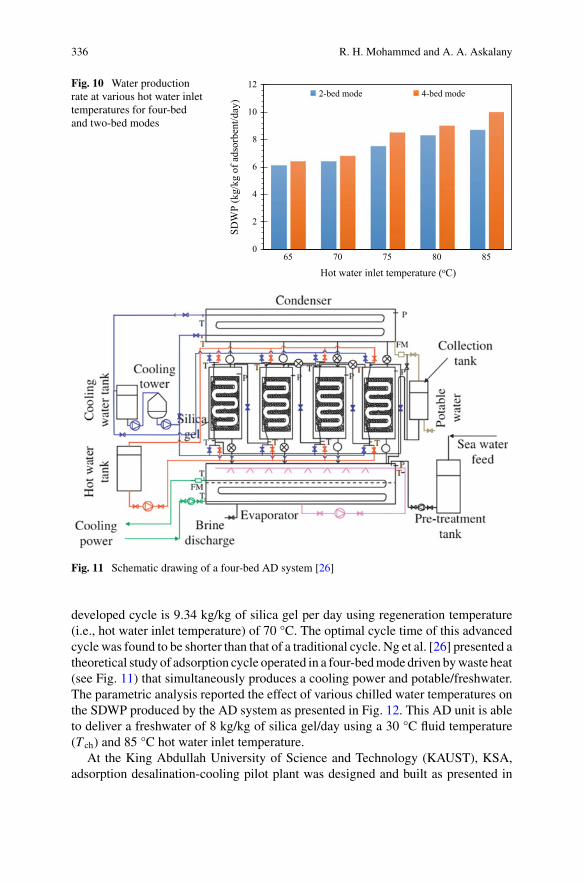
336 R. H. Mohammed and A. A. Askalany
Fig. 10 Water productionrate at various hot water inlettemperatures for four-bedand two-bed modes
0
2
4
6
8
10
12
65 70 75 80 85
SDW
P (k
g/kg
of a
dsor
bent
/day
)
Hot water inlet temperature (oC)
2-bed mode 4-bed mode
Fig. 11 Schematic drawing of a four-bed AD system [26]
developed cycle is 9.34 kg/kg of silica gel per day using regeneration temperature(i.e., hot water inlet temperature) of 70 °C. The optimal cycle time of this advancedcycle was found to be shorter than that of a traditional cycle. Ng et al. [26] presented atheoretical study of adsorption cycle operated in a four-bedmode driven bywaste heat(see Fig. 11) that simultaneously produces a cooling power and potable/freshwater.The parametric analysis reported the effect of various chilled water temperatures onthe SDWP produced by the AD system as presented in Fig. 12. This AD unit is ableto deliver a freshwater of 8 kg/kg of silica gel/day using a 30 °C fluid temperature(T ch) and 85 °C hot water inlet temperature.
At the King Abdullah University of Science and Technology (KAUST), KSA,adsorption desalination-cooling pilot plant was designed and built as presented in
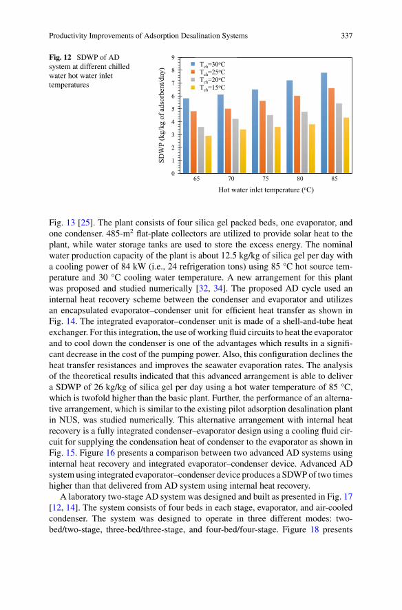
Productivity Improvements of Adsorption Desalination Systems 337
Fig. 12 SDWP of ADsystem at different chilledwater hot water inlettemperatures
0
1
2
3
4
5
6
7
8
9
65 70 75 80 85
SDW
P (k
g/kg
of a
dsor
bent
/day
)
Hot water inlet temperature (oC)
Tch=30oCTch=25oCTch=20oCTch=15oC
Tch=30oC Tch=25oC Tch=20oC Tch=15oC
Fig. 13 [25]. The plant consists of four silica gel packed beds, one evaporator, andone condenser. 485-m2 flat-plate collectors are utilized to provide solar heat to theplant, while water storage tanks are used to store the excess energy. The nominalwater production capacity of the plant is about 12.5 kg/kg of silica gel per day witha cooling power of 84 kW (i.e., 24 refrigeration tons) using 85 °C hot source tem-perature and 30 °C cooling water temperature. A new arrangement for this plantwas proposed and studied numerically [32, 34]. The proposed AD cycle used aninternal heat recovery scheme between the condenser and evaporator and utilizesan encapsulated evaporator–condenser unit for efficient heat transfer as shown inFig. 14. The integrated evaporator–condenser unit is made of a shell-and-tube heatexchanger. For this integration, the use of working fluid circuits to heat the evaporatorand to cool down the condenser is one of the advantages which results in a signifi-cant decrease in the cost of the pumping power. Also, this configuration declines theheat transfer resistances and improves the seawater evaporation rates. The analysisof the theoretical results indicated that this advanced arrangement is able to delivera SDWP of 26 kg/kg of silica gel per day using a hot water temperature of 85 °C,which is twofold higher than the basic plant. Further, the performance of an alterna-tive arrangement, which is similar to the existing pilot adsorption desalination plantin NUS, was studied numerically. This alternative arrangement with internal heatrecovery is a fully integrated condenser–evaporator design using a cooling fluid cir-cuit for supplying the condensation heat of condenser to the evaporator as shown inFig. 15. Figure 16 presents a comparison between two advanced AD systems usinginternal heat recovery and integrated evaporator–condenser device. Advanced ADsystem using integrated evaporator–condenser device produces a SDWPof two timeshigher than that delivered from AD system using internal heat recovery.
A laboratory two-stage AD system was designed and built as presented in Fig. 17[12, 14]. The system consists of four beds in each stage, evaporator, and air-cooledcondenser. The system was designed to operate in three different modes: two-bed/two-stage, three-bed/three-stage, and four-bed/four-stage. Figure 18 presents
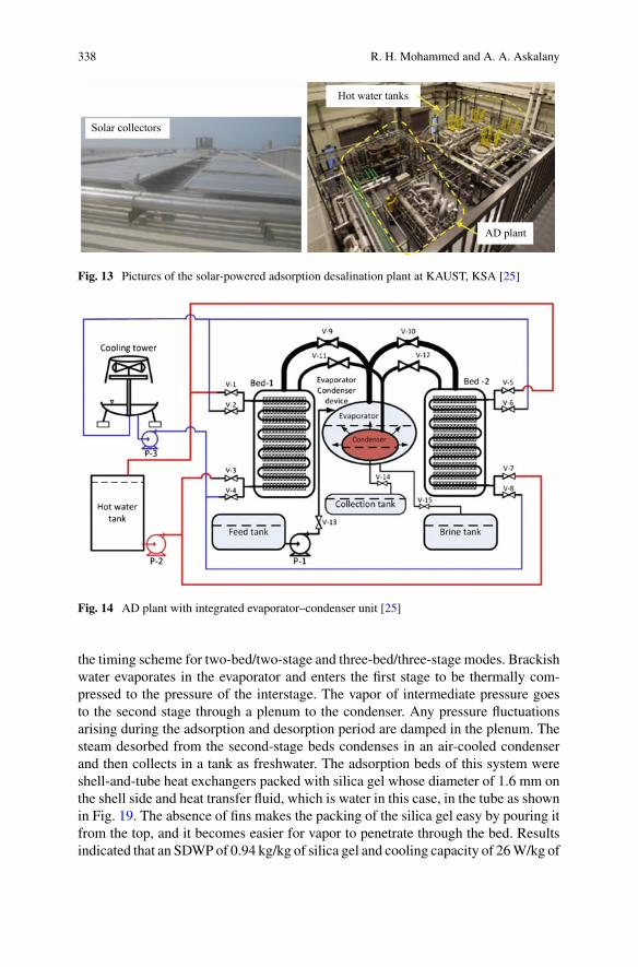
338 R. H. Mohammed and A. A. Askalany
Hot water tanks
Solar collectors
AD plant
Fig. 13 Pictures of the solar-powered adsorption desalination plant at KAUST, KSA [25]
Fig. 14 AD plant with integrated evaporator–condenser unit [25]
the timing scheme for two-bed/two-stage and three-bed/three-stage modes. Brackishwater evaporates in the evaporator and enters the first stage to be thermally com-pressed to the pressure of the interstage. The vapor of intermediate pressure goesto the second stage through a plenum to the condenser. Any pressure fluctuationsarising during the adsorption and desorption period are damped in the plenum. Thesteam desorbed from the second-stage beds condenses in an air-cooled condenserand then collects in a tank as freshwater. The adsorption beds of this system wereshell-and-tube heat exchangers packed with silica gel whose diameter of 1.6 mm onthe shell side and heat transfer fluid, which is water in this case, in the tube as shownin Fig. 19. The absence of fins makes the packing of the silica gel easy by pouring itfrom the top, and it becomes easier for vapor to penetrate through the bed. Resultsindicated that an SDWPof 0.94 kg/kg of silica gel and cooling capacity of 26W/kg of
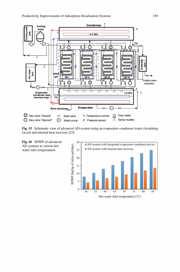
Productivity Improvements of Adsorption Desalination Systems 339
Fig. 15 Schematic view of advanced AD system using an evaporator–condenser water circulatingcircuit and internal heat recovery [25]
Fig. 16 SDWP of advancedAD systems at various hotwater inlet temperatures
0
5
10
15
20
25
30
50 55 60 65 70 75 80 85
SDW
P (k
g/kg
of s
ilica
gel
/day
)
Hot water inlet temperature (oC)
AD system with integrated evaporator-condenser deviceAD system with internal heat recovery
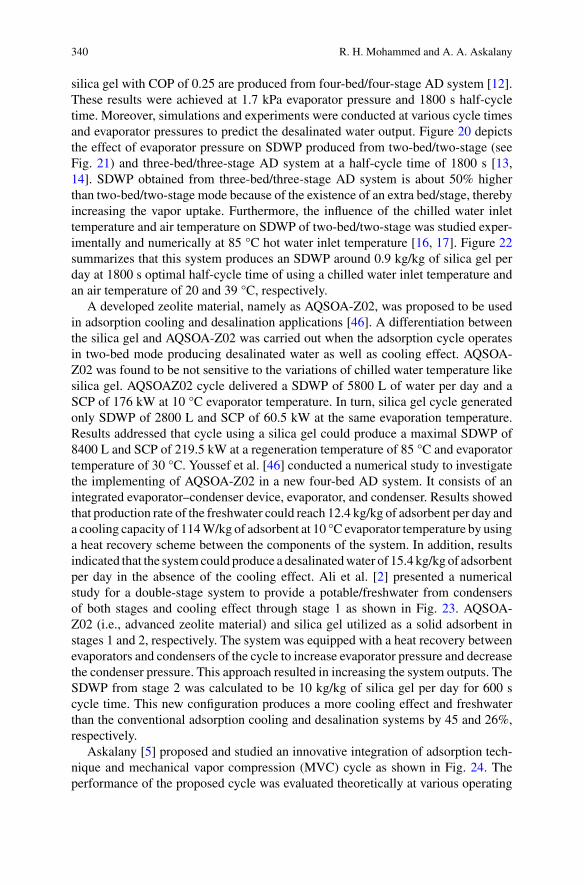
340 R. H. Mohammed and A. A. Askalany
silica gel with COP of 0.25 are produced from four-bed/four-stage AD system [12].These results were achieved at 1.7 kPa evaporator pressure and 1800 s half-cycletime. Moreover, simulations and experiments were conducted at various cycle timesand evaporator pressures to predict the desalinated water output. Figure 20 depictsthe effect of evaporator pressure on SDWP produced from two-bed/two-stage (seeFig. 21) and three-bed/three-stage AD system at a half-cycle time of 1800 s [13,14]. SDWP obtained from three-bed/three-stage AD system is about 50% higherthan two-bed/two-stage mode because of the existence of an extra bed/stage, therebyincreasing the vapor uptake. Furthermore, the influence of the chilled water inlettemperature and air temperature on SDWP of two-bed/two-stage was studied exper-imentally and numerically at 85 °C hot water inlet temperature [16, 17]. Figure 22summarizes that this system produces an SDWP around 0.9 kg/kg of silica gel perday at 1800 s optimal half-cycle time of using a chilled water inlet temperature andan air temperature of 20 and 39 °C, respectively.
A developed zeolite material, namely as AQSOA-Z02, was proposed to be usedin adsorption cooling and desalination applications [46]. A differentiation betweenthe silica gel and AQSOA-Z02 was carried out when the adsorption cycle operatesin two-bed mode producing desalinated water as well as cooling effect. AQSOA-Z02 was found to be not sensitive to the variations of chilled water temperature likesilica gel. AQSOAZ02 cycle delivered a SDWP of 5800 L of water per day and aSCP of 176 kW at 10 °C evaporator temperature. In turn, silica gel cycle generatedonly SDWP of 2800 L and SCP of 60.5 kW at the same evaporation temperature.Results addressed that cycle using a silica gel could produce a maximal SDWP of8400 L and SCP of 219.5 kW at a regeneration temperature of 85 °C and evaporatortemperature of 30 °C. Youssef et al. [46] conducted a numerical study to investigatethe implementing of AQSOA-Z02 in a new four-bed AD system. It consists of anintegrated evaporator–condenser device, evaporator, and condenser. Results showedthat production rate of the freshwater could reach 12.4 kg/kg of adsorbent per day anda cooling capacity of 114W/kg of adsorbent at 10 °C evaporator temperature by usinga heat recovery scheme between the components of the system. In addition, resultsindicated that the systemcould produce a desalinatedwater of 15.4 kg/kg of adsorbentper day in the absence of the cooling effect. Ali et al. [2] presented a numericalstudy for a double-stage system to provide a potable/freshwater from condensersof both stages and cooling effect through stage 1 as shown in Fig. 23. AQSOA-Z02 (i.e., advanced zeolite material) and silica gel utilized as a solid adsorbent instages 1 and 2, respectively. The system was equipped with a heat recovery betweenevaporators and condensers of the cycle to increase evaporator pressure and decreasethe condenser pressure. This approach resulted in increasing the system outputs. TheSDWP from stage 2 was calculated to be 10 kg/kg of silica gel per day for 600 scycle time. This new configuration produces a more cooling effect and freshwaterthan the conventional adsorption cooling and desalination systems by 45 and 26%,respectively.
Askalany [5] proposed and studied an innovative integration of adsorption tech-nique and mechanical vapor compression (MVC) cycle as shown in Fig. 24. Theperformance of the proposed cycle was evaluated theoretically at various operating
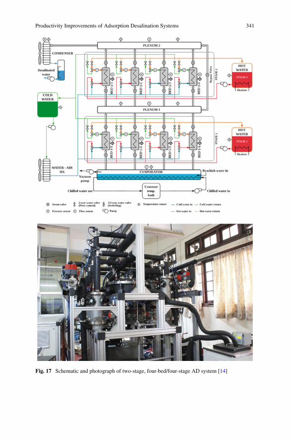
Productivity Improvements of Adsorption Desalination Systems 341
Fig. 17 Schematic and photograph of two-stage, four-bed/four-stage AD system [14]
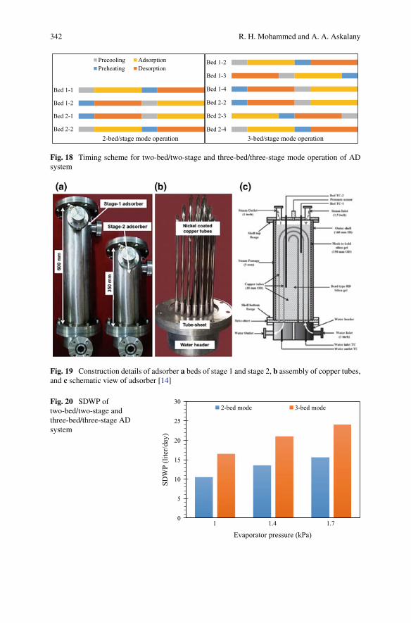
342 R. H. Mohammed and A. A. Askalany
Bed 2-2
Bed 2-1
Bed 1-2
Bed 1-1
2-bed/stage mode operation
Precooling AdsorptionPreheating Desorption
Bed 2-4
Bed 2-3
Bed 2-2
Bed 1-4
Bed 1-3
Bed 1-2
3-bed/stage mode operation
Fig. 18 Timing scheme for two-bed/two-stage and three-bed/three-stage mode operation of ADsystem
Fig. 19 Construction details of adsorber a beds of stage 1 and stage 2, b assembly of copper tubes,and c schematic view of adsorber [14]
Fig. 20 SDWP oftwo-bed/two-stage andthree-bed/three-stage ADsystem
0
5
10
15
20
25
30
1 1.4 1.7
SDW
P (li
ter/d
ay)
Evaporator pressure (kPa)
2-bed mode 3-bed mode
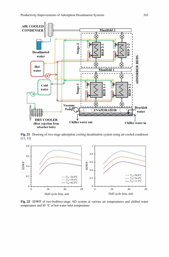
Productivity Improvements of Adsorption Desalination Systems 343
Fig. 21 Drawing of two-stage adsorption cooling desalination system using air-cooled condenser[13, 14]
0
0.2
0.4
0.6
0.8
0 20 40 60
SDW
P
Half cycle time, min
Tc=36oC39oC42oC
0
0.2
0.4
0.6
0.8
1
0 20 40 60
SDW
P
Half cycle time, min
Tch=11.5oCSeries2Series3
Tch=20.0oCTch=16.0oC Tch=11.5oC
Tair=36.0oCTair=39.0oC Tair=42.0oC
Fig. 22 SDWP of two-bed/two-stage AD system at various air temperatures and chilled watertemperature and 85 °C of hot water inlet temperature
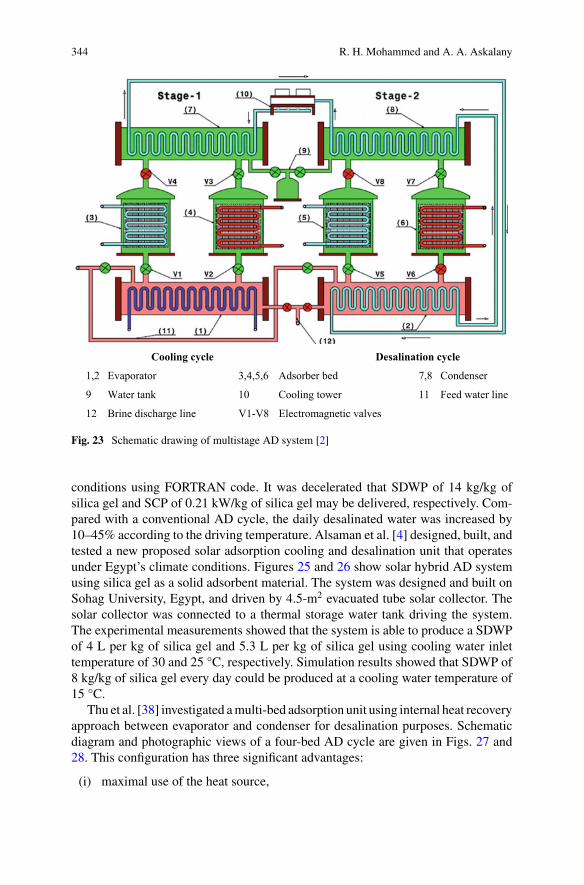
344 R. H. Mohammed and A. A. Askalany
Cooling cycle Desalination cycle
1,2 Evaporator 3,4,5,6 Adsorber bed 7,8 Condenser
9 Water tank 10 Cooling tower 11 Feed water line
12 Brine discharge line V1-V8 Electromagnetic valves
Fig. 23 Schematic drawing of multistage AD system [2]
conditions using FORTRAN code. It was decelerated that SDWP of 14 kg/kg ofsilica gel and SCP of 0.21 kW/kg of silica gel may be delivered, respectively. Com-pared with a conventional AD cycle, the daily desalinated water was increased by10–45% according to the driving temperature. Alsaman et al. [4] designed, built, andtested a new proposed solar adsorption cooling and desalination unit that operatesunder Egypt’s climate conditions. Figures 25 and 26 show solar hybrid AD systemusing silica gel as a solid adsorbent material. The system was designed and built onSohag University, Egypt, and driven by 4.5-m2 evacuated tube solar collector. Thesolar collector was connected to a thermal storage water tank driving the system.The experimental measurements showed that the system is able to produce a SDWPof 4 L per kg of silica gel and 5.3 L per kg of silica gel using cooling water inlettemperature of 30 and 25 °C, respectively. Simulation results showed that SDWP of8 kg/kg of silica gel every day could be produced at a cooling water temperature of15 °C.
Thu et al. [38] investigated amulti-bed adsorption unit using internal heat recoveryapproach between evaporator and condenser for desalination purposes. Schematicdiagram and photographic views of a four-bed AD cycle are given in Figs. 27 and28. This configuration has three significant advantages:
(i) maximal use of the heat source,
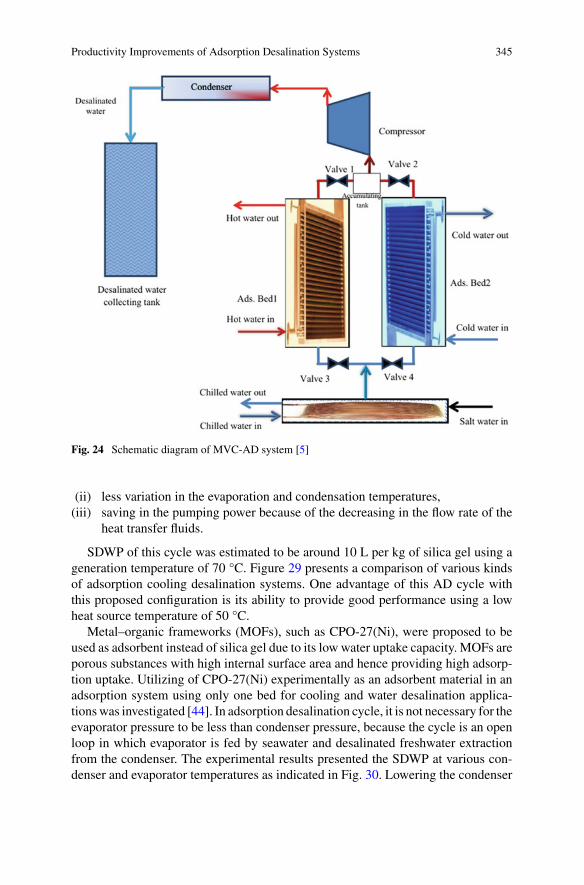
Productivity Improvements of Adsorption Desalination Systems 345
Fig. 24 Schematic diagram of MVC-AD system [5]
(ii) less variation in the evaporation and condensation temperatures,(iii) saving in the pumping power because of the decreasing in the flow rate of the
heat transfer fluids.
SDWP of this cycle was estimated to be around 10 L per kg of silica gel using ageneration temperature of 70 °C. Figure 29 presents a comparison of various kindsof adsorption cooling desalination systems. One advantage of this AD cycle withthis proposed configuration is its ability to provide good performance using a lowheat source temperature of 50 °C.
Metal–organic frameworks (MOFs), such as CPO-27(Ni), were proposed to beused as adsorbent instead of silica gel due to its low water uptake capacity. MOFs areporous substances with high internal surface area and hence providing high adsorp-tion uptake. Utilizing of CPO-27(Ni) experimentally as an adsorbent material in anadsorption system using only one bed for cooling and water desalination applica-tionswas investigated [44]. In adsorption desalination cycle, it is not necessary for theevaporator pressure to be less than condenser pressure, because the cycle is an openloop in which evaporator is fed by seawater and desalinated freshwater extractionfrom the condenser. The experimental results presented the SDWP at various con-denser and evaporator temperatures as indicated in Fig. 30. Lowering the condenser
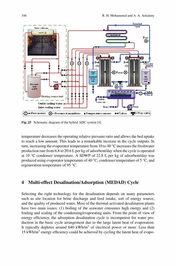
346 R. H. Mohammed and A. A. Askalany
Fig. 25 Schematic diagram of the hybrid ADC system [4]
temperature decreases the operating relative pressure ratio and allows the bed uptaketo reach a low amount. This leads to a remarkable increase in the cycle outputs. Inturn, increasing the evaporator temperature from 10 to 40 °C increases the freshwaterproduction rate from 6.8 to 20.6 L per kg of adsorbent/day when the cycle is operatedat 10 °C condenser temperature. A SDWP of 22.8 L per kg of adsorbent/day wasproduced using evaporator temperature of 40 °C, condenser temperature of 5 °C, andregeneration temperature of 95 °C.
4 Multi-effect Desalination/Adsorption (MEDAD) Cycle
Selecting the right technology for the desalination depends on many parameterssuch as site location for brine discharge and feed intake, sort of energy source,and the quality of produced water. Most of the thermal-activated desalination plantshave two main issues: (1) boiling of the seawater consumes high energy and (2)fouling and scaling of the condensing/evaporating units. From the point of view ofenergy efficiency, the adsorption desalination cycle is incompetent for water pro-duction in the basic cycle arrangement due to the large latent heat of evaporation.It typically depletes around 640 kWh/m3 of electrical power or more. Less than15 kWh/m3 energy efficiency could be achieved by cycling the latent heat of evapo-
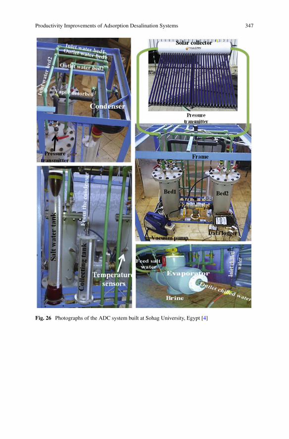
Productivity Improvements of Adsorption Desalination Systems 347
Fig. 26 Photographs of the ADC system built at Sohag University, Egypt [4]
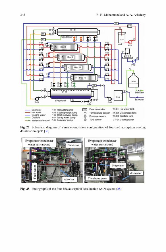
348 R. H. Mohammed and A. A. Askalany
Fig. 27 Schematic diagram of a master-and-slave configuration of four-bed adsorption coolingdesalination cycle [38]
Fig. 28 Photographs of the four-bed adsorption desalination (AD) system [38]
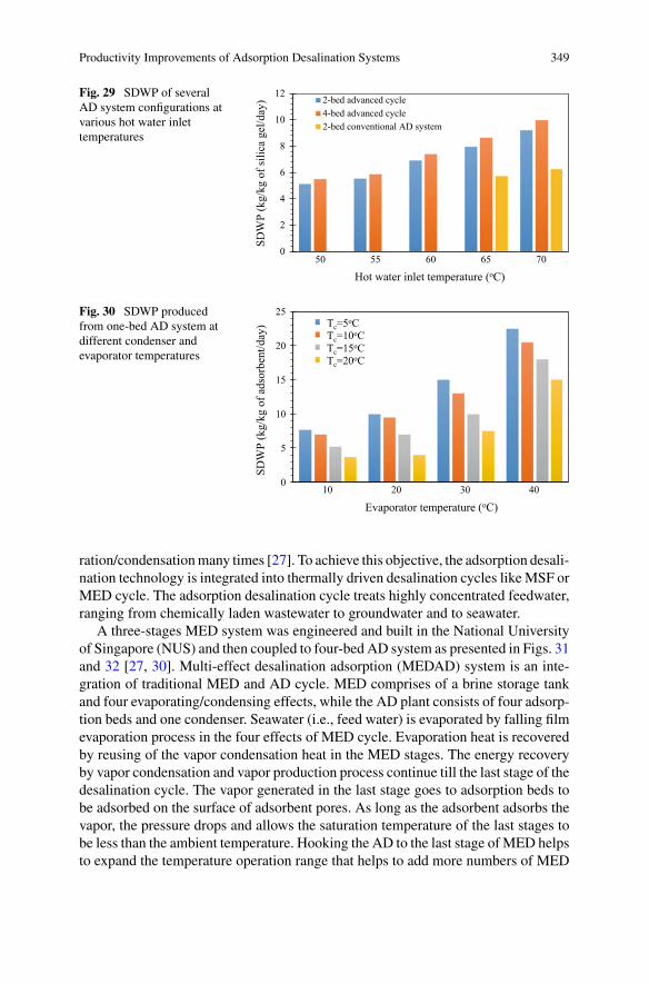
Productivity Improvements of Adsorption Desalination Systems 349
Fig. 29 SDWP of severalAD system configurations atvarious hot water inlettemperatures
0
2
4
6
8
10
12
50 55 60 65 70SD
WP
(kg/
kg o
f sili
ca g
el/d
ay)
Hot water inlet temperature (oC)
2-bed advanced cycle4-bed advanced cycle2-bed conventional AD system
Fig. 30 SDWP producedfrom one-bed AD system atdifferent condenser andevaporator temperatures
0
5
10
15
20
25
10 20 30 40
SDW
P (k
g/kg
of a
dsor
bent
/day
)
Evaporator temperature (oC)
Tc=5oCTc=10oCTc=20oCTc=30oC
Tc=5oCTc=10oCTc=15oCTc=20oC
ration/condensationmany times [27]. To achieve this objective, the adsorption desali-nation technology is integrated into thermally driven desalination cycles likeMSF orMED cycle. The adsorption desalination cycle treats highly concentrated feedwater,ranging from chemically laden wastewater to groundwater and to seawater.
A three-stages MED system was engineered and built in the National Universityof Singapore (NUS) and then coupled to four-bed AD system as presented in Figs. 31and 32 [27, 30]. Multi-effect desalination adsorption (MEDAD) system is an inte-gration of traditional MED and AD cycle. MED comprises of a brine storage tankand four evaporating/condensing effects, while the AD plant consists of four adsorp-tion beds and one condenser. Seawater (i.e., feed water) is evaporated by falling filmevaporation process in the four effects of MED cycle. Evaporation heat is recoveredby reusing of the vapor condensation heat in the MED stages. The energy recoveryby vapor condensation and vapor production process continue till the last stage of thedesalination cycle. The vapor generated in the last stage goes to adsorption beds tobe adsorbed on the surface of adsorbent pores. As long as the adsorbent adsorbs thevapor, the pressure drops and allows the saturation temperature of the last stages tobe less than the ambient temperature. Hooking the AD to the last stage ofMED helpsto expand the temperature operation range that helps to add more numbers of MED
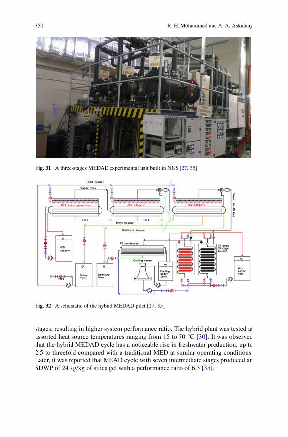
350 R. H. Mohammed and A. A. Askalany
Fig. 31 A three-stages MEDAD experimental unit built in NUS [27, 35]
Fig. 32 A schematic of the hybrid MEDAD pilot [27, 35]
stages, resulting in higher system performance ratio. The hybrid plant was tested atassorted heat source temperatures ranging from 15 to 70 °C [30]. It was observedthat the hybrid MEDAD cycle has a noticeable rise in freshwater production, up to2.5 to threefold compared with a traditional MED at similar operating conditions.Later, it was reported that MEAD cycle with seven intermediate stages produced anSDWP of 24 kg/kg of silica gel with a performance ratio of 6.3 [35].
Productivity Improvements of Adsorption Desalination Systems 351
5 Trend of AD System in the Near Future
Adsorption-based desalination plants powered by solar energy have been built andinstalled at KAUST in Saudi Arabia and at NUS in Singapore. Different systemshave been installed in Singapore that use waste heat. In Saudi Arabia, three large-scale systems will be implemented in the near future for desalination purposes.Specific electrical energy consumption of less than 1.5 kW/m3 has been reported forAD technology, which is substantially less than seawater desalination using tradi-tional thermal-based and membrane-based technologies [22]. Although the theoreti-cal invented and developed cycles of water desalination using adsorption/desorptionphenomena are not so recent, the experimental investigations are still in the cradlewith age less than 20 years. During this short period, specific daily water produc-tion from experimental AD systems is still under 10 kg/kg of silica gel/day with anascending increase in the last few years. This may lead to an expectation of intensiveresearches that might be conducted in the next few years in this field.
Based on the above-figured state of the art, one could extract some beneficialdata that could help in predicting the near future of the adsorption desalinationtechnology. The presented data could be summarized in Table 2 and Fig. 33. It canbe seen that silica gel comes first undisputed adsorbent of the applied materials inAD experimental systems. The maximum SDWP could be achieved until now is lessthan 25 kg/kg of adsorbent per day.
6 Conclusion
The efficient use of the renewable energy is the prime mover of the future sustainabledevelopment of desalination plants. Energy and water systems are interconnected asenergy is required to produce clean water and provide cooling power. Brackish orseawater is used in the adsorption cycle to produce potable water and cooling poweras well. This hybridization has been proposed for energy efficiency improvementand system performance enhancement. Recent developments in the working pairsused in different arrangements of hybrid adsorption-based desalination (AD) sys-tem are reviewed in this chapter. It is shown that the water production and coolingpower mainly depend on the ability of the adsorbent materials to adsorb vapor andthe adsorption rate of the bed. Therefore, the picking up an appropriate working pairis a key parameter for designing an efficient hybrid adsorption-based desalinationplant. It is highlighted that the operating conditions and cycle time of the systemsignificantly affect the water production. Reviewing the developments of this sys-tem in the last decades reveals that the adsorption system could produce potablewater of 25 kg/kg of adsorbent when it is integrated with multi-effect desalination(MED) cycle. This integration also reduces the corrosion in the MED system andincreases its production by twofold compared with traditional MED systems. Thelow water production rate produced by hybrid adsorption-based desalination system
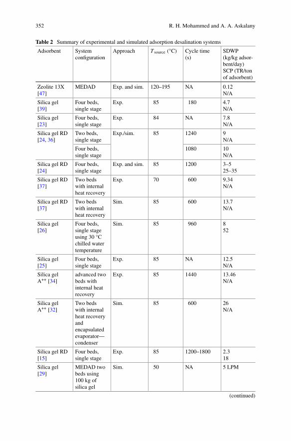
352 R. H. Mohammed and A. A. Askalany
Table 2 Summary of experimental and simulated adsorption desalination systems
Adsorbent Systemconfiguration
Approach T source (°C) Cycle time(s)
SDWP(kg/kg adsor-bent/day)SCP (TR/tonof adsorbent)
Zeolite 13X[47]
MEDAD Exp. and sim. 120–195 NA 0.12N/A
Silica gel[39]
Four beds,single stage
Exp. 85 180 4.7N/A
Silica gel[23]
Four beds,single stage
Exp. 84 NA 7.8N/A
Silica gel RD[24, 36]
Two beds,single stage
Exp./sim. 85 1240 9N/A
Four beds,single stage
1080 10N/A
Silica gel RD[24]
Four beds,single stage
Exp. and sim. 85 1200 3–525–35
Silica gel RD[37]
Two bedswith internalheat recovery
Exp. 70 600 9.34N/A
Silica gel RD[37]
Two bedswith internalheat recovery
Sim. 85 600 13.7N/A
Silica gel[26]
Four beds,single stageusing 30 °Cchilled watertemperature
Sim. 85 960 852
Silica gel[25]
Four beds,single stage
Exp. 85 NA 12.5N/A
Silica gelA++ [34]
advanced twobeds withinternal heatrecovery
Exp. 85 1440 13.46N/A
Silica gelA++ [32]
Two bedswith internalheat recoveryandencapsulatedevaporator—condenser
Sim. 85 600 26N/A
Silica gel RD[15]
Four beds,single stage
Exp. 85 1200–1800 2.318
Silica gel[29]
MEDAD twobeds using100 kg ofsilica gel
Sim. 50 NA 5 LPM
(continued)
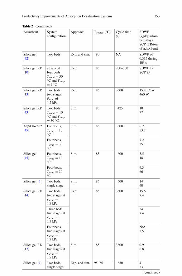
Productivity Improvements of Adsorption Desalination Systems 353
Table 2 (continued)
Adsorbent Systemconfiguration
Approach T source (°C) Cycle time(s)
SDWP(kg/kg adsor-bent/day)SCP (TR/tonof adsorbent)
Silica gel[42]
Two beds Exp. and sim. 80 NA SDWP of0.315 during105 s
Silica gel RD[10]
advancedfour bedsT cond = 30°C and T evap= 7 °C
Exp. 85 200–700 SDWP 12SCP 25
Silica gel RD[13]
Two beds,two stages,Pevap of1.7 kPa.
Exp. 85 3600 15.8 L/day460 W
Silica gel RD[43]
Two bedsT cond = 10°C and T evap= 30 °C
Sim. 85 425 1077
AQSOA-Z02[45]
Four beds,T evap = 10°C
Sim. 85 600 6.253.7
Four beds,T evap = 30°C
7.255
Silica gel[45]
Four beds,T evap = 10°C
Sim. 85 600 3.518
Four beds,T evap = 30°C
9.366
Silica gel [5] Two beds,single stage
Sim. 85 500 1460
Silica gel RD[14]
Two beds,two stages atPevap =1.7 kPa
Exp. 85 3600 15.67.4
Three beds,two stages atPevap =1.7 kPa
247.4
Four beds,two stages atPevap =1.7 kPa
N/A5.5
Silica gel RD[17]
Two beds,two stages atPevap =1.7 kPa
Sim. 85 3800 0.96.8
Silica gel [4] Two beds,single stage
Exp. and sim. 95–75 650 433
(continued)
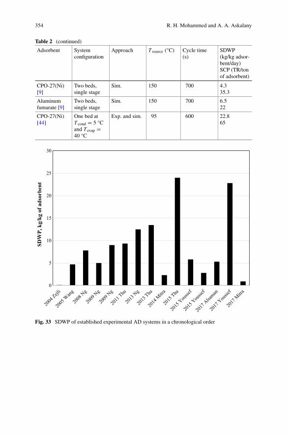
354 R. H. Mohammed and A. A. Askalany
Table 2 (continued)
Adsorbent Systemconfiguration
Approach T source (°C) Cycle time(s)
SDWP(kg/kg adsor-bent/day)SCP (TR/tonof adsorbent)
CPO-27(Ni)[9]
Two beds,single stage
Sim. 150 700 4.335.3
Aluminumfumarate [9]
Two beds,single stage
Sim. 150 700 6.522
CPO-27(Ni)[44]
One bed atT cond = 5 °Cand T evap =40 °C
Exp. and sim. 95 600 22.865
0
5
10
15
20
25
30
SDW
P, k
g/kg
of a
dsor
bent
Fig. 33 SDWP of established experimental AD systems in a chronological order
Productivity Improvements of Adsorption Desalination Systems 355
is controlled by thermal response of the adsorption bed and mass transfer insidethe adsorbent material. Therefore, more research and developments are inevitable todesign adsorption beds with low thermal resistance and high adsorption rate to beable to achieve more folds in water production. Lowering the cost to be less thanUS$0.5/m3 of potable water will be an additional challenge that needs to be over-come. Achieving these goals will help in designing a new generation of AD systemthat will be able to compete with the other desalination technologies and meet theincreasing demand of clean water especially in rural and remote coastal areas.
References
1. Al-Kharabsheh S, Goswami DY (2004) Theoretical analysis of a water desalination systemusing low grade solar heat. J SolEnergy Eng 126(2):774–780
2. Ali SM, Chakraborty A (2016) Adsorption assisted double stage cooling and desalinationemploying silica gel + water and AQSOA-Z02 + water systems. Energy Convers Manag117:193–205
3. Alsaman AS et al (2016) A state of the art of hybrid adsorption desalination–cooling systems.Renew Sustain Energy Rev 58:692–703
4. Alsaman AS et al (2017) Performance evaluation of a solar-driven adsorption desalination-cooling system. Energy 128:196–207
5. AskalanyAA (2016) Innovativemechanical vapor compression adsorption desalination (MVC-AD) system. Appl Therm Eng 106:286–292
6. Askalany AA et al (2012) A review on adsorption cooling systems with adsorbent carbon.Renew Sustain Energy Rev 16(1):493–500
7. Broughton DB (1984). Continuous Desalination Process. USPO 4,447,3298. El-Sharkawy I et al (2007) Performance improvement of adsorption desalination plant: exper-
imental investigation. Int Rev Mech Eng 1(1):25–319. Elsayed E et al (2017) CPO-27 (Ni), aluminium fumarate and MIL-101 (Cr) MOF materials
for adsorption water desalination. Desalination 406:25–3610. Ghaffour N et al (2014) Renewable energy-driven innovative energy-efficient desalination
technologies. Appl Energy 136:1155–116511. Li Z et al (2018) Towards sustainability in water-energy nexus: ocean energy for seawater
desalination. Renew Sustain Energy Rev 82:3833–384712. Mitra S et al (2014) Simulation study of a two-stage adsorber system. Appl Therm Eng
72(2):283–28813. Mitra S et al (2015) Performance evaluation of a two-stage silica gel+water adsorption based
cooling-cum-desalination system. Int J Refrig 58:186–19814. Mitra S et al (2016) Development and performance studies of an air cooled two-stagemulti-bed
silica-gel + water adsorption system. Int J Refrig 67:174–18915. Mitra S et al (2014) Solar driven adsorption desalination system. Energy Procedia
49:2261–226916. Mitra S et al (2017) Performance evaluation and determination of minimum desorption temper-
ature of a two-stage air cooled silica gel/water adsorption system. Appl Energy 206:507–51817. Mitra S et al (2017) Modeling study of two-stage, multi-bed air cooled silica gel + water
adsorption cooling cum desalination system. Appl Therm Eng 114:704–71218. Mohammed RH et al (2017) Novel compact bed design for adsorption cooling systems: para-
metric numerical study. Int J Refrig 80:238–25119. Mohammed RH et al (2018) Performance evaluation of a new modular packed bed for adsorp-
tion cooling systems. Appl Therm Eng 136:293–300
356 R. H. Mohammed and A. A. Askalany
20. Mohammed RH et al (2018) Scaling analysis of heat and mass transfer processes in an adsorp-tion packed bed. Int J Therm Sci 133:82–89
21. Mohammed RH et al (2018) Revisiting the adsorption equilibrium equations of silica gel/waterfor adsorption cooling applications. Int J Refrig 86:40–47
22. Ng KC (2014) Adsorption desalination (AD) technology. From https://20e80c98e0ab55004687-1b7b51f623edb7707bfb25abfa60d496.ssl.cf6.rackcdn.com/Medad%20Technologies_TechXchange.pdf
23. Ng KC et al (2008) Adsorption desalination quenches global thirst. Heat Transfer Eng29(10):845–848
24. Ng KC et al (2009) Solar-assisted dual-effect adsorption cycle for the production of coolingeffect and potable water. Int J Low-Carbon Technol 4(2):61–67
25. NgKCet al (2013)Adsorption desalination: an emerging low-cost thermal desalinationmethod.Desalination 308:161–179
26. Ng KC et al (2012) Study on a waste heat-driven adsorption cooling cum desalination cycle.Int J Refrig 35(3):685–693
27. Saha BB et al (2016) Fundamental and application aspects of adsorption cooling and desalina-tion. Appl Therm Eng 97:68–76
28. Sayılgan SÇ et al (2016) Effect of regeneration temperature on adsorption equilibria and massdiffusivity of zeolite 13x-water pair. Microporous Mesoporous Mater 224:9–16
29. Shahzad MW et al (2014) Multi effect desalination and adsorption desalination (MEDAD): ahybrid desalination method. Appl Therm Eng 72(2):289–297
30. ShahzadMWet al (2015) An experimental investigation onMEDADhybrid desalination cycle.Appl Energy 148:273–281
31. Teo HWB et al (2017) Water adsorption on CHA and AFI types zeolites: modelling and inves-tigation of adsorption chiller under static and dynamic conditions. Appl Therm Eng 127:35–45
32. ThuK et al (2013) Numerical simulation and performance investigation of an advanced adsorp-tion desalination cycle. Desalination 308:209–218
33. Thu K et al (2013) Thermo-physical properties of silica gel for adsorption desalination cycle.Appl Therm Eng 50(2):1596–1602
34. Thu K et al (2013) Performance investigation of advanced adsorption desalination cycle withcondenser–evaporator heat recovery scheme. Desalin Water Treat 51(1–3):150–163
35. Thu K et al (2015) Performance investigation of an advanced multi-effect adsorption desali-nation (MEAD) cycle. Appl Energy 159:469–477
36. Thu K et al (2009) Operational strategy of adsorption desalination systems. Int J Heat MassTransf 52(7):1811–1816
37. Thu K et al (2011) Study on an advanced adsorption desalination cycle with evaporator–con-denser heat recovery circuit. Int J Heat Mass Transf 54(1–3):43–51
38. Thu K et al (2017) Performance investigation on a 4-bed adsorption desalination cycle withinternal heat recovery scheme. Desalination 402:88–96
39. Wang X, Ng KC (2005) Experimental investigation of an adsorption desalination plant usinglow-temperature waste heat. Appl Therm Eng 25(17–18):2780–2789
40. Wang X et al (2007) How heat and mass recovery strategies impact the performance of adsorp-tion desalination plant: theory and experiments. Heat Transfer Eng 28(2):147–153
41. Wang X et al (2004) Investigation on the isotherm of silica gel+ water systems. J Therm AnalCalorim 76(2):659–669
42. Wu JW et al (2014) Dynamic model for the optimisation of adsorption-based desalinationprocesses. Appl Therm Eng 66(1–2):464–473
43. Youssef P et al (2015) Effect of evaporator and condenser temperatures on the performance ofadsorption desalination cooling cycle. Energy Procedia 75:1464–1469
44. Youssef PG et al (2017) Experimental investigation of adsorption water desalination/coolingsystem using CPO-27Ni MOF. Desalination 404:192–199
45. Youssef PG et al (2015) Performance analysis of four bed adsorption water desalina-tion/refrigeration system, comparison of AQSOA-Z02 to silica-gel. Desalination 375:100–107

Productivity Improvements of Adsorption Desalination Systems 357
46. Youssef PG et al (2016) Numerical simulation of combined adsorption desalination and coolingcycles with integrated evaporator/condenser. Desalination 392:14–24
47. Zejli D et al (2004) A solar adsorption desalination device: first simulation results. Desalination168:127–135
Related Documents