MIT (T) MQC SY (B.TECH) Chapter: 03 Angular Measurement Introduction: The angle is defined as the opening between two lines which meet at a point. (Vertex of the angle) The basic unit in angular measurement is the right angle, which is defined as the angle between two lines which intersect so as to make the adjacent angle equal. If the circle is divided into 360 equal parts each part is called as degree (⁰). Each degree is divided in 60 minutes (‘) and each minutes into 60 seconds (“). This method of defining angular units is called as sexagesimal system, which is used engineering purpose. Sexagesimal is a numeral system with sixty as its base. An alternative method of defining angle is based on the relationship between the radius and arc of a circle. It called radian. Radian is defined as the angle subtended at the centre by an arc of a circle of length equal to its radius. Widely used in mathematical investigation. Kishor S. Patil [email protected] θ=k s r Length of the arc s Radius of the circle r Scaling constant k (which depends on the units of measurement that are chosen): deg ¿ rad × 180 ° π One radian is equal to 180/π degrees = 57.2958⁰ Degrees 0° 30° 45° 60° 90° 180° 270°

angular measurement
Nov 24, 2014
Welcome message from author
This document is posted to help you gain knowledge. Please leave a comment to let me know what you think about it! Share it to your friends and learn new things together.
Transcript
MIT (T) MQC SY (B.TECH)
Chapter: 03
Angular Measurement
Introduction:
The angle is defined as the opening between two lines which meet at a point. (Vertex of the angle) The basic unit in angular measurement is the right angle, which is defined as the angle between two
lines which intersect so as to make the adjacent angle equal. If the circle is divided into 360 equal parts each part is called as degree ( ).⁰ Each degree is divided in 60 minutes (‘) and each minutes into 60 seconds (“).
This method of defining angular units is called as sexagesimal system, which is used engineering purpose. Sexagesimal is a numeral system with sixty as its base.
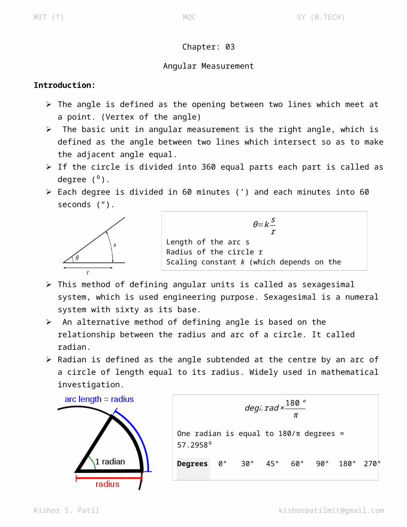
An alternative method of defining angle is based on the relationship between the radius and arc of a circle. It called radian.
Radian is defined as the angle subtended at the centre by an arc of a circle of length equal to its radius. Widely used in mathematical investigation.
Instruments for Angular Measurements:
Many instruments which are available used for angular measurement. Selection of instrument depends upon the component and the accuracy of measurement. As concerned metrological work high precision work may be measured in few seconds to obtain high
accuracy. Following instruments are generally used for angular measurement:
1. Vernier Bevel Protractor2. Combination Protractor3. Universal bevel Protractor4. Sine bar5. Sine centre
Kishor S. Patil [email protected]
θ=k sr
Length of the arc sRadius of the circle rScaling constant k (which depends on the units of measurement that are chosen):
deg¿ rad × 180 °π
One radian is equal to 180/π degrees = 57.2958⁰
Degrees 0° 30° 45° 60° 90° 180° 270°
Radians 0 π
MIT (T) MQC SY (B.TECH)6. Angle gauge block7. Auto collimator8. Angle dekkor9. Roller and cylindrical method10. Optical prism method.
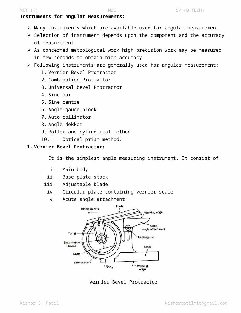
1. Vernier Bevel Protractor:
It is the simplest angle measuring instrument. It consist of
i. Main bodyii. Base plate stock
iii. Adjustable bladeiv. Circular plate containing vernier scalev. Acute angle attachment
Vernier Bevel Protractor
The base plate is attached to the main body and adjustable blade is attached to the circular plate containing vernier scale.
A circle can be divided into 360 equal angles. Each angle is called degree. So a circle is 360 degrees (360o).
An acute angle attachment is provided at the top for measuring acute angle.. The blade can be moved along throughout its length and can also be reversed. The acute acute angle attachment can be readily fitted into the body and clamped in any position. As shown in fig the main scale is graduated in degree of arc. The vernier scale has 12 divisions each side of centre zero. These are marked 0-60 minutes of arc. So that each division equals 1/12 or 60, that is 5minuts of arc.
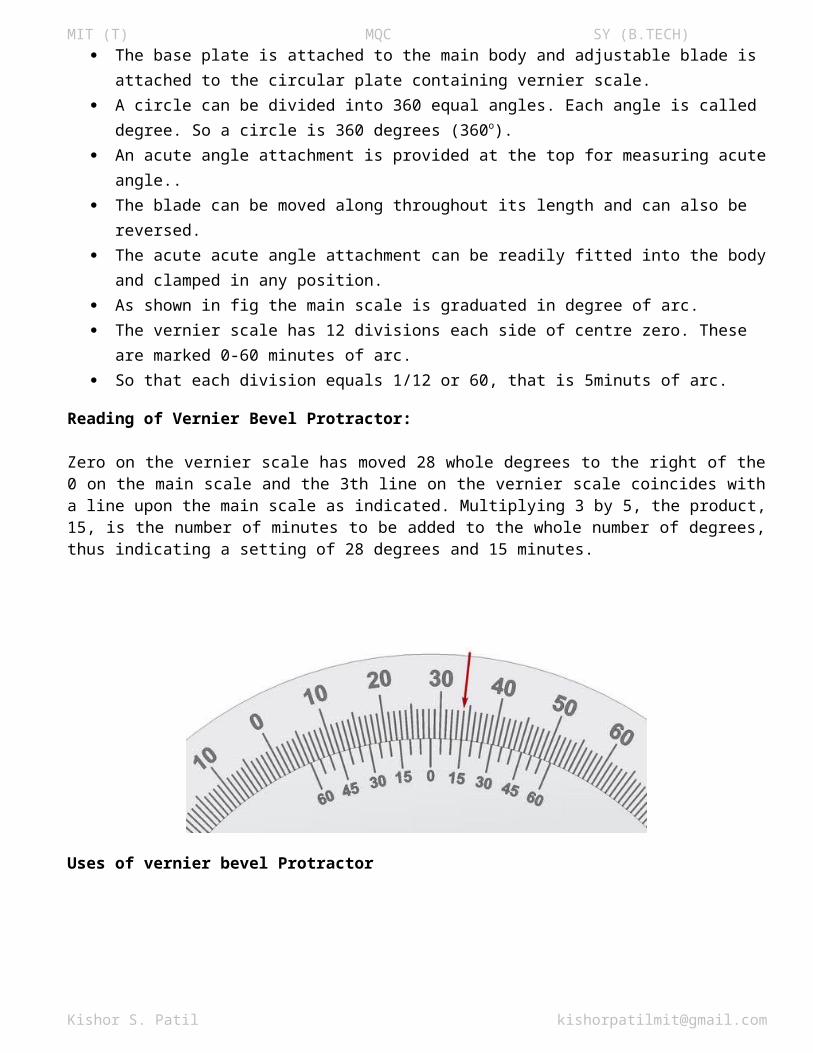
Reading of Vernier Bevel Protractor:
Zero on the vernier scale has moved 28 whole degrees to the right of the 0 on the main scale and the 3th line on the vernier scale coincides with a line upon the main scale as indicated. Multiplying 3 by 5, the product, 15, is the number of minutes to be added to the whole number of degrees, thus indicating a setting of 28 degrees and 15 minutes.
Kishor S. Patil [email protected]
MIT (T) MQC SY (B.TECH)
Uses of vernier bevel Protractor
Inside beveled face of a ground surface For checking v blocks For measuring acute angle etc.
Kishor S. Patil [email protected]
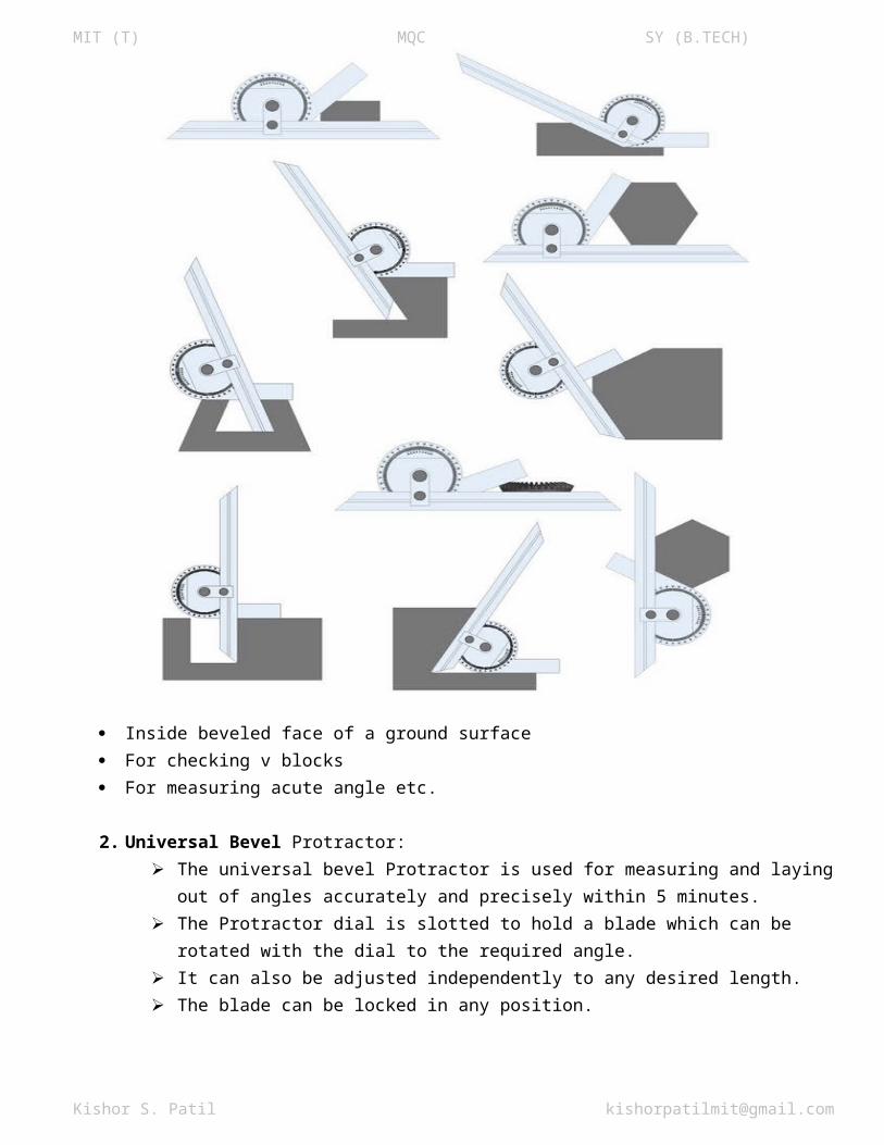
MIT (T) MQC SY (B.TECH)2. Universal Bevel Protractor:
The universal bevel Protractor is used for measuring and laying out of angles accurately and precisely within 5 minutes.
The Protractor dial is slotted to hold a blade which can be rotated with the dial to the required angle.
It can also be adjusted independently to any desired length. The blade can be locked in any position.
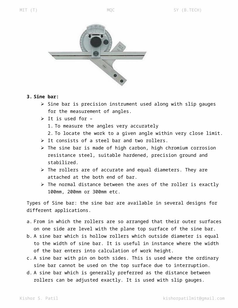
3. Sine bar: Sine bar is precision instrument used along with slip gauges for the measurement of angles. It is used for –
1. To measure the angles very accurately 2. To locate the work to a given angle within very close limit.
It consists of a steel bar and two rollers. The sine bar is made of high carbon, high chromium corrosion resistance steel, suitable
hardened, precision ground and stabilized. The rollers are of accurate and equal diameters. They are attached at the both end of bar. The normal distance between the axes of the roller is exactly 100mm, 200mm or 300mm etc.
Types of Sine bar: the sine bar are available in several designs for different applications.
a. From in which the rollers are so arranged that their outer surfaces on one side are level with the plane top surface of the sine bar.
b. A sine bar which is hollow rollers which outside diameter is equal to the width of sine bar. It is useful in instance where the width of the bar enters into calculation of work height.
c. A sine bar with pin on both sides. This is used where the ordinary sine bar cannot be used on the top surface due to interruption.
d. A sine bar which is generally preferred as the distance between rollers can be adjusted exactly. It is used with slip gauges.
Kishor S. Patil [email protected]
MIT (T) MQC SY (B.TECH)
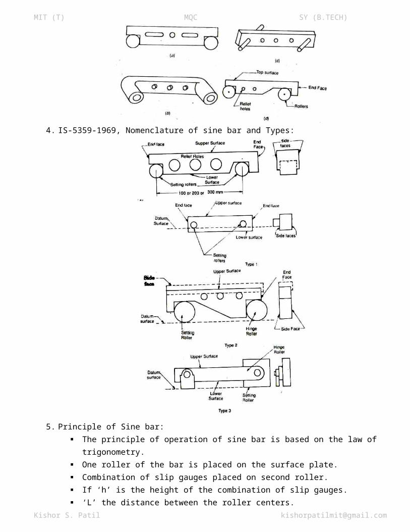
4. IS-5359-1969, Nomenclature of sine bar and Types:
5. Principle of Sine bar: The principle of operation of sine bar is based on the law of trigonometry. One roller of the bar is placed on the surface plate. Combination of slip gauges placed on second roller. If ‘h’ is the height of the combination of slip gauges. ‘L’ the distance between the roller centers.
Then sin θ=hL∨θ=sin−1( h
L)
Kishor S. Patil [email protected]
MIT (T) MQC SY (B.TECH)
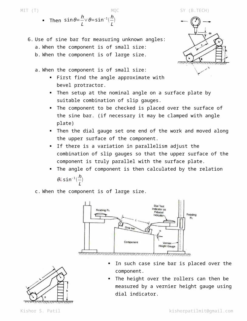
6. Use of sine bar for measuring unknown angles:a. When the component is of small size:b. When the component is of large size.
a. When the component is of small size: First find the angle approximate with bevel protractor. Then setup at the nominal angle on a surface plate by
suitable combination of slip gauges. The component to be checked is placed over the surface
of the sine bar. (if necessary it may be clamped with angle plate) Then the dial gauge set one end of the work and moved along the upper surface of the
component. If there is a variation in parallelism adjust the combination of slip gauges so that the upper
surface of the component is truly parallel with the surface plate.
The angle of component is then calculated by the relation θ ¿ sin−1( hL)
c. When the component is of large size.
In such case sine bar is placed over the component. The height over the rollers can then be measured by a vernier height gauge using dial
indicator. The height gauge is thus used to obtain two readings, if ‘h’ is the difference in the height
and ‘L’ distance between the roller centers of the sine bar, then θ ¿ sin−1( hL)
Another Method:
Kishor S. Patil [email protected]
MIT (T) MQC SY (B.TECH)
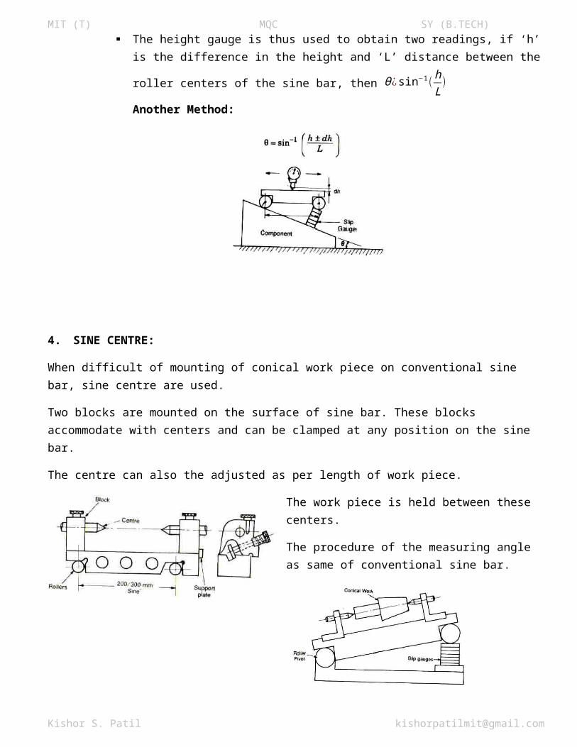
4. SINE CENTRE:
When difficult of mounting of conical work piece on conventional sine bar, sine centre are used.
Two blocks are mounted on the surface of sine bar. These blocks accommodate with centers and can be clamped at any position on the sine bar.
The centre can also the adjusted as per length of work piece.
The work piece is held between these centers.
The procedure of the measuring angle as same of conventional sine bar.
Sine Table.
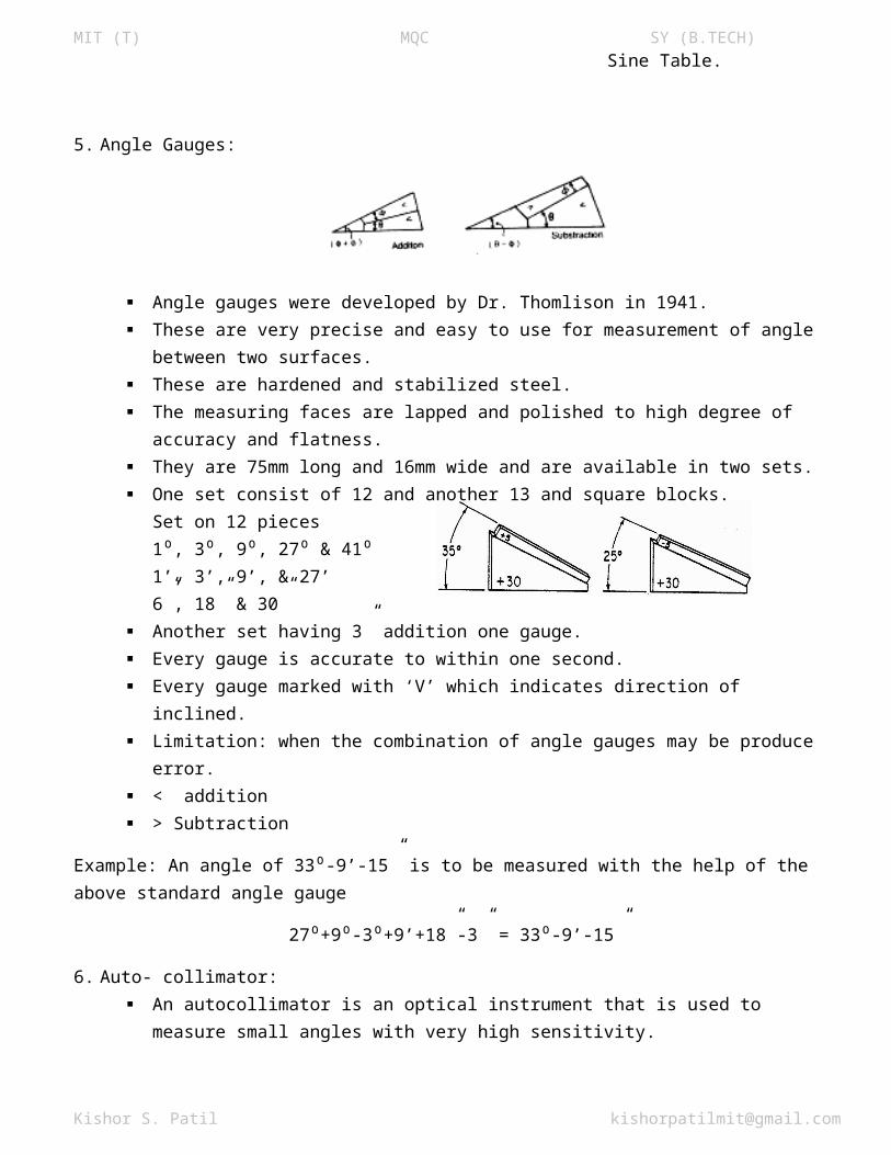
5. Angle Gauges:
Angle gauges were developed by Dr. Thomlison in 1941. These are very precise and easy to use for measurement of angle between two surfaces.
Kishor S. Patil [email protected]
MIT (T) MQC SY (B.TECH) These are hardened and stabilized steel. The measuring faces are lapped and polished to high degree of accuracy and flatness. They are 75mm long and 16mm wide and are available in two sets. One set consist of 12 and another 13 and square blocks.
Set on 12 pieces1 , 3 , 9⁰ ⁰ ⁰, 27⁰ & 41⁰1’, 3’, 9’, & 27’6”, 18” & 30”
Another set having 3” addition one gauge. Every gauge is accurate to within one second. Every gauge marked with ‘V’ which indicates direction of inclined. Limitation: when the combination of angle gauges may be produce error. < addition > Subtraction
Example: An angle of 33 -9’-15” is to be measured with the help of the above standard angle gauge⁰
27 +9 -3 +9’+18”-3” = 33 -9’-15”⁰ ⁰ ⁰ ⁰
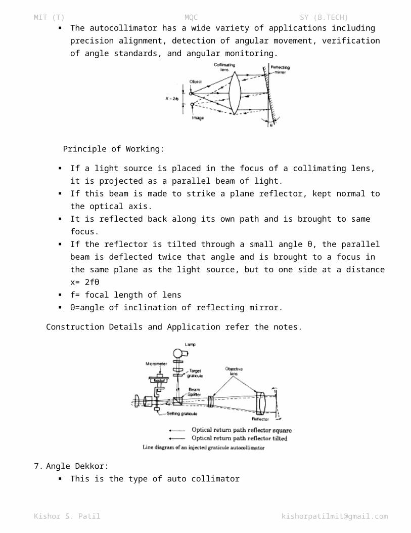
6. Auto- collimator: An autocollimator is an optical instrument that is used to measure small angles with very high
sensitivity. The autocollimator has a wide variety of applications including precision alignment, detection of
angular movement, verification of angle standards, and angular monitoring.
Principle of Working:
If a light source is placed in the focus of a collimating lens, it is projected as a parallel beam of light.
If this beam is made to strike a plane reflector, kept normal to the optical axis. It is reflected back along its own path and is brought to same focus. If the reflector is tilted through a small angle θ, the parallel beam is deflected twice that angle and
is brought to a focus in the same plane as the light source, but to one side at a distance x= 2fθ f= focal length of lens θ=angle of inclination of reflecting mirror.
Construction Details and Application refer the notes.
Kishor S. Patil [email protected]
MIT (T) MQC SY (B.TECH)
7. Angle Dekkor: This is the type of auto collimator It consist of microscope, collimating lens and two scale engraved on a glass screen which is place
in the focal plane of the objective lens. One of the scales called datum scale is horizontal and fixed. It is engraved across the centre of the
screen and always visible in the microscope eye piece. Another scale is an illuminated vertical scale fixed across the centre of the screen and the
reflected image of the illuminated scale is received at right angles of the fixed scale, and the two scales, in the position intersect each other.
Thus the reading on illuminated scale measures angular deviations from one axis at 90 to the ⁰optical axis, and the reading on the fixed datum scale measures the deviations about an axis mutually perpendicular to the other two.
Thus the change in angular position of the reflector in two planes is indicated by change in the point of intersection of two scales.
Kishor S. Patil [email protected]
MIT (T) MQC SY (B.TECH)
8. Taper Measurement:Use of precision balls and rollers:
Kishor S. Patil [email protected]
Related Documents


