ANGLE MODULATION CHAPTER 3

Welcome message from author
This document is posted to help you gain knowledge. Please leave a comment to let me know what you think about it! Share it to your friends and learn new things together.
Transcript

ANGLE MODULATION
CHAPTER 3

ANGLE MODULATION
Part 1Introduction

Introduction
Angle modulation is the process by which the angle (frequency or phase) of the carrier signal is changed in accordance with the instantaneous amplitude of modulating or message signal.
Cont’d…
classified into two types such as Frequency modulation (FM) Phase modulation (PM)
Used for : Commercial radio broadcasting Television sound transmission Two way mobile radio Cellular radio Microwave and satellite communication system
Cont’d…Advantages over AM:
Freedom from interference: all natural and external noise consist of amplitude variations, thus receiver usually cannot distinguish between amplitude of noise or desired signal. AM is noisy than FM.
Operate in very high frequency band (VHF): 88MHz-108MHz
Can transmit musical programs with higher degree of fidelity.

FREQUENCY MODULATION PRINCIPLES
In FM the carrier amplitude remains constant, the carrier frequency varies with the amplitude of modulating signal.
The amount of change in carrier frequency produced by the modulating signal is known as frequency deviation.

Res
ting
f c
Incr
easi
ng f c In
crea
sing
f c
Dec
reas
ing
f c
Res
ting
f c
Mod
ulat
ing
sign
alC
arri
erFM

PHASE MODULATION(PM)
The process by which changing the phase of carrier signal in accordance with the instantaneous of message signal. The amplitude remains constant after the modulation process.
Mathematical analysis: Let message signal:
And carrier signal:
tVt mmm cos
]cos[ tVt ccc

PM (cont’d)
Where = phase angle of carrier signal. It is changed in accordance with the amplitude of the message signal;
i.e. After phase modulation the instantaneous voltage will be
or
Where mp = Modulation index of phase modulation K is a constant and called deviation sensitivities of the phase
tKVtKV mmm cos)(
)tcosmtcos(V)t(v
)tcosKVtcos(V)t(v
mpCCpm
mmCCpm

FREQUENCY MODULATION (FM)
A process where the frequency of the carrier wave varies with the magnitude variations of the modulating or audio signal.
The amplitude of the carrier wave is kept constant.

FM(cont’d)
Mathematical analysis: Let message signal:
And carrier signal:
tVt mmm cos
]cos[ tVt ccc

FM (cont’d)
During the process of frequency modulations the frequency of carrier signal is changed in accordance with the instantaneous amplitude of message signal .Therefore the frequency of carrier after modulation is written as
To find the instantaneous phase angle of modulated signal, integrate equation above w.r.t. t
tcosVKtvK mm1Cm1ci
tsinVKtdttcosVKdt mm
m1Cmm1Cii

FM(cont’d)
Thus, we get the FM wave as:
Where modulation index for FM is given by
)tsinVKtcos(VcosVc)t(v mm
m1CC1FM
)sincos()( tmtVtv mfCCFM
m
m1f
VKm

FM(cont’d)
Frequency deviation: ∆f is the relative placement of carrier frequency (Hz) w.r.t its unmodulated value. Given as:
m1Cmax VK
m1Cmin VK
m1minCCmaxd VK
2VK
2f m1d

FM(cont’d)
Therefore:
mf
m1
ffm
;2VKf

Equations for Phase- and Frequency-Modulated Carriers
TomasiElectronic Communications Systems, 5e
Copyright ©2004 by Pearson Education, Inc.Upper Saddle River, New Jersey 07458
All rights reserved.

Example (FM)
Determine the peak frequency deviation (∆f) and modulation index (m) for an FM modulator with a deviation sensitivity K1 = 5 kHz/V and a modulating signal,
)t20002cos(2)t(vm

Example (PM)
Determine the peak phase deviation (m) for a PM modulator with a deviation sensitivity K = 2.5 rad/V and a modulating signal, )t20002cos(2)t(vm

FM&PM (Bessel function)
Thus, for general equation:
)coscos()( tmtVtv mfCCFM
2nncos)m(J)cosmcos(
nn
n
mcnC 2ntntcos)m(JV)t(m

Bessel function
2
t)(cos)m(J2
t)(cos)m(Jtcos)m(J{Vtv mCf1mCf1Cf0CFM
)...}m(J...t)2(cos)m(Jt)2(cos)m(J fnmCf2mCf2

B.F. (cont’d) It is seen that each pair of side band is preceded by J
coefficients. The order of the coefficient is denoted by subscript m. The Bessel function can be written as
N = number of the side frequency Mf = modulation index
....
!2!22/
!1!12/1
2
42
nm
nm
nm
mJ ffn
ffn

B.F. (cont’d)

Bessel Functions of the First Kind, Jn(m) for some value of modulation index

Representation of frequency spectrum

Example
For an FM modulator with a modulation index m = 1, a modulating signal vm(t) = Vmsin(2π1000t), and an unmodulated carrier vc(t) = 10sin(2π500kt). Determine the number of sets of significant side frequencies and their amplitudes. Then, draw the frequency spectrum showing their relative amplitudes.
Angle ModulationPart 2
FM BandwidthPower distribution of FM Generation & Detection of FMApplication of FM
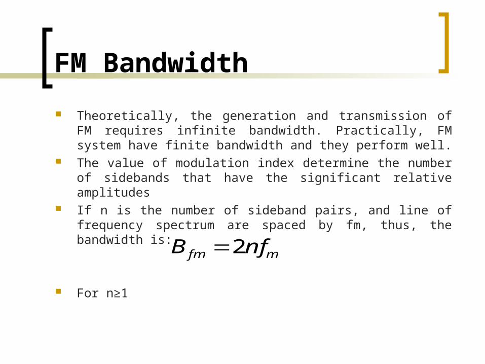
FM Bandwidth Theoretically, the generation and transmission of FM
requires infinite bandwidth. Practically, FM system have finite bandwidth and they perform well.
The value of modulation index determine the number of sidebands that have the significant relative amplitudes
If n is the number of sideband pairs, and line of frequency spectrum are spaced by fm, thus, the bandwidth is:
For n≥1
mfm nfB 2
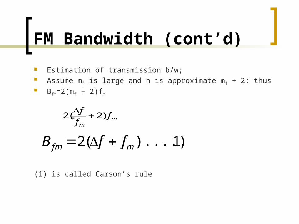
FM Bandwidth (cont’d) Estimation of transmission b/w; Assume mf is large and n is approximate mf + 2; thus Bfm=2(mf + 2)fm
=
(1) is called Carson’s rule
mm
fff )2(2
)1)........((2 mfm ffB

Example
For an FM modulator with a peak frequency deviation, Δf = 10 kHz, a modulating-signal frequency fm = 10 kHz, Vc = 10 V and a 500 kHz carrier, determine Actual minimum bandwidth from the Bessel
function table. Approximate minimum bandwidth using
Carson’s rule.Then
Plot the output frequency spectrum for the Bessel approximation.

Deviation Ratio (DR)
The worse case modulation index which produces the widest output frequency spectrum.
Where ∆f(max) = max. peak frequency deviation fm(max) = max. modulating signal frequency
(max)
(max)
mffDR

Example
Determine the deviation ratio and bandwidth for the worst-case (widest-bandwidth) modulation index for an FM broadcast-band transmitter with a maximum frequency deviation of 75 kHz and a maximum modulating-signal frequency of 15 kHz.
Determine the deviation ratio and maximum bandwidth for an equal modulation index with only half the peak frequency deviation and modulating-signal frequency.

FM Power Distribution
As seen in Bessel function table, it shows that as the sideband relative amplitude increases, the carrier amplitude,J0 decreases.
This is because, in FM, the total transmitted power is always constant and the total average power is equal to the unmodulated carrier power, that is the amplitude of the FM remains constant whether or not it is modulated.

FM Power Distribution (cont’d)
In effect, in FM, the total power that is originally in the carrier is redistributed between all components of the spectrum, in an amount determined by the modulation index, mf, and the corresponding Bessel functions.
At certain value of modulation index, the carrier component goes to zero, where in this condition, the power is carried by the sidebands only.

Average Power
The average power in unmodulated carrier
The total instantaneous power in the angle modulated carrier.
The total modulated power
R2VP
2c
c
R2V)]t(2t2cos[
21
21
RVP
)]t(t[cosRV
R)t(mP
2c
c
2c
t
c2
2c
2
t
RV
RV
RV
RVPPPPP nc
nt 2)(2..
2)(2
2)(2
2..
222
21
2
210

Example
For an FM modulator with a modulation index m = 1, a modulating signal
vm(t) = Vmsin(2π1000t), and an unmodulated carrier
vc(t) = 10sin(2π500kt). Determine the unmodulated carrier power for the FM modulator given with a load resistance, RL = 50Ω. Determine also the total power in the angle-modulated wave.

Quiz For an FM modulator with modulation index,
m = 2, modulating signal, vm(t) = Vmcos(2π2000t), and an unmodulated carrier, vc(t) = 10 cos(2π800kt).
a) Determine the number of sets of significant sidebands.b) Determine their amplitudes.c) Draw the frequency spectrum showing the relative
amplitudes of the side frequencies.d) Determine the bandwidth.e) Determine the total power of the modulated wave.

Generation of FM
Two major FM generation:i) Direct method:
i) straight forward, requires a VCO whose oscillation frequency has linear dependence on applied voltage.
ii) Advantage: large frequency deviationiii) Disadvantage: the carrier frequency tends to drift
and must be stabilized.iv) Common methods:
i) FM Reactance modulatorsii) Varactor diode modulators

1) Reactance modulator
Generation of FM (cont’d)

2) Varactor diode modulator
Generation of FM (cont’d)

Generation of FM (cont’d)
ii) Indirect method: i. Frequency-up conversion.ii. Two ways:
a. Heterodyne methodb. Multiplication method
iii. One most popular indirect method is the Armstrong modulator

Wideband Armstrong Modulator

A complete Armstrong modulator is supposed to provide a 75kHz frequency deviation. It uses a balanced modulator and 90o phase shifter to phase- modulate a crystal oscillator. Required deviation is obtained by combination of multipliers and mixing, raise the signal from suitable for broadcasting.
Armstrong Modulator
kHz75MHz2.90toHz47.14kHz400

FM Detection/Demodulation
FM demodulation
is a process of getting back or regenerate the original modulating signal from the modulated FM signal.
It can be achieved by converting the frequency deviation of FM signal to the variation of equivalent voltage.
The demodulator will produce an output where its instantaneous amplitude is proportional to the instantaneous frequency of the input FM signal.
FM detection (cont’d)
To detect an FM signal, it is necessary to have a circuit whose output voltage varies linearly with the frequency of the input signal.
The most commonly used demodulator is the PLL demodulator. Can be use to detect either NBFM or WBFM.

PLL Demodulator
Phase detector
VCO
Low pass filter Amplifier
FM input
Vc(t)
fvco
V0(t)
fi

PLL Demodulator
The phase detector produces an average output voltage that is linear function of the phase difference between the two input signals. Then low frequency component is pass through the LPF to get a small dc average voltage to the amplifier.
After amplification, part of the signal is fed back through VCO where it results in frequency modulation of the VCO frequency. When the loop is in lock, the VCO frequency follows or tracks the incoming frequency.
PLL Demodulator
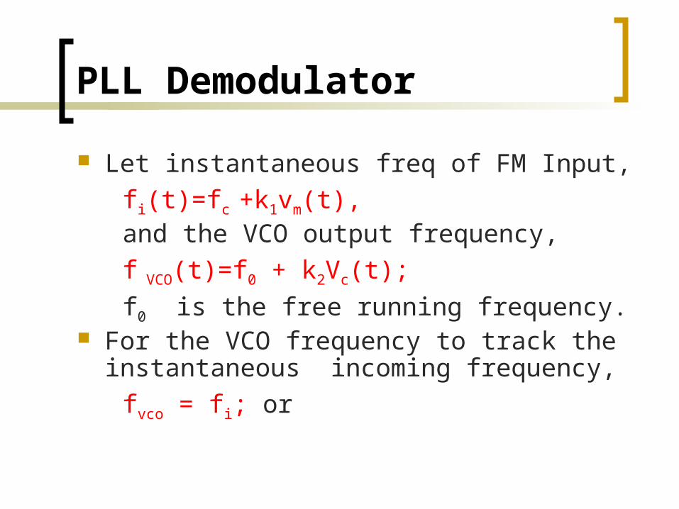
Let instantaneous freq of FM Input, fi(t)=fc +k1vm(t), and the VCO output frequency, f VCO(t)=f0 + k2Vc(t); f0 is the free running frequency. For the VCO frequency to track the
instantaneous incoming frequency, fvco = fi; or

PLL Demodulator
f0 + k2Vc(t)= fc +k1vm(t), so,
If VCO can be tuned so that fc=f0, then
Where Vc(t) is also taken as the output voltage, which therefore is the demodulated output
)()( 10 tvkfftV mcc
)()( 1 tvktV mc

Comparison AM and FM Its the SNR can be increased without increasing transmitted power
about 25dB higher than in AM
Certain forms of interference at the receiver are more easily to suppressed, as FM receiver has a limiter which eliminates the amplitude variations and fluctuations.
The modulation process can take place at a low level power stage in the transmitter, thus a low modulating power is needed.
Power content is constant and fixed, and there is no waste of power transmitted
There are guard bands in FM systems allocated by the standardization body, which can reduce interference between the adjacent channels.

Application of FM
FM is commonly used at VHF radio frequencies for high-fidelity broadcasts of music and speech (FM broadcasting). Normal (analog) TV sound is also broadcast using FM. The type of FM used in broadcast is generally called wide-FM, or W-FM
A narrowband form is used for voice communications in commercial and amateur radio settings. In two-way radio, narrowband narrow-fm (N-FM) is used to conserve bandwidth. In addition, it is used to send signals into space.

Summary of angle modulation-what you need to be familiar with

Summary (cont’d)

Summary (cont’d)
Bandwidth:a) Actual minimum bandwidth from Bessel
table:
b) Approximate minimum bandwidth using Carson’s rule:
)(2 mfnB
)(2 mffB
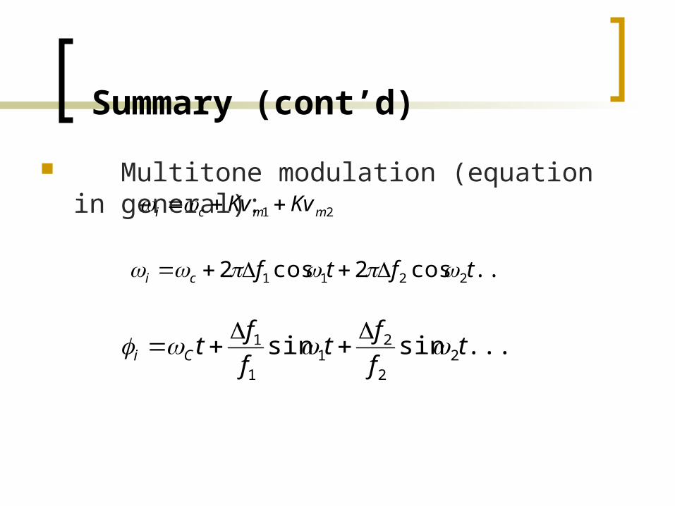
Summary (cont’d)
Multitone modulation (equation in general):21 mmci KvKv
....cos2cos2 2211 tftfci
......sinsin 22
21
1
1 tfft
fftCi

Summary (cont’d)
..].........sinsincos[
]sinsincos[
cos
2211
22
21
1
1
tmtmtV
tfft
fftVtv
Vtv
ffCC
CCfm
iCfm

Summary (cont’d)-Comparison NBFM&WBFM

ANGLE MODULATION
Part 3Advantages Disadvantages

Advantages
Wideband FM gives significant improvement in the SNR at the output of the RX which proportional to the square of modulation index.
Angle modulation is resistant to propagation-induced selective fading since amplitude variations are unimportant and are removed at the receiver using a limiting circuit.
Angle modulation is very effective in rejecting interference. (minimizes the effect of noise).
Angle modulation allows the use of more efficient transmitter power in information.
Angle modulation is capable of handing a greater dynamic range of modulating signal without distortion than AM.

Disadvantages
Angle modulation requires a transmission bandwidth much larger than the message signal bandwidth.
Angle modulation requires more complex and expensive circuits than AM.

END OF ANGLE MODULATION

Exercise
Determine the deviation ratio and worst-case bandwidth for an FM signal with a maximum frequency deviation 25 kHz and maximum modulating signal 12.5 kHz.

Exercise 2
For an FM modulator with 40-kHz frequency deviation and a modulating-signal frequency 10 kHz, determine the bandwidth using both Carson’s rule and Bessel table.

Exercise 3
For an FM modulator with an unmodulated carrier amplitude 20 V, a modulation index, m = 1, and a load resistance of 10-ohm, determine the power in the modulated carrier and each side frequency, and sketch the power spectrum for the modulated wave.

Exercise 4
A frequency modulated signal (FM) has the following expression:
The frequency deviation allowed in this system is 75 kHz. Calculate the: Modulation index Bandwidth required, using Carson’s rule
)1010sin10400cos(38)( 36 tmttv ffm
Related Documents