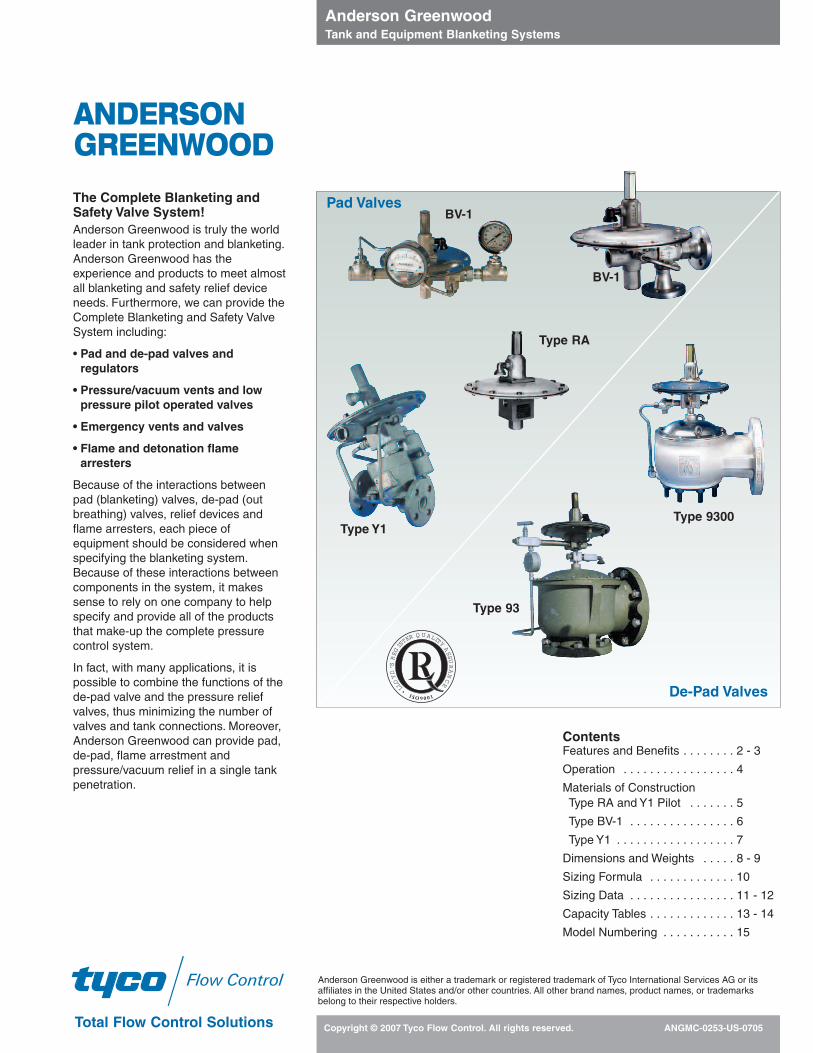
The Complete Blanketing and Safety Valve System! Anderson Greenwood is truly the world leader in tank protection and blanketing. Anderson Greenwood has the experience and products to meet almost all blanketing and safety relief device needs. Furthermore, we can provide the Complete Blanketing and Safety Valve System including: • Pad and de-pad valves and regulators • Pressure/vacuum vents and low pressure pilot operated valves • Emergency vents and valves • Flame and detonation flame arresters Because of the interactions between pad (blanketing) valves, de-pad (out breathing) valves, relief devices and flame arresters, each piece of equipment should be considered when specifying the blanketing system. Because of these interactions between components in the system, it makes sense to rely on one company to help specify and provide all of the products that make-up the complete pressure control system. In fact, with many applications, it is possible to combine the functions of the de-pad valve and the pressure relief valves, thus minimizing the number of valves and tank connections. Moreover, Anderson Greenwood can provide pad, de-pad, flame arrestment and pressure/vacuum relief in a single tank penetration. Contents Features and Benefits . . . . . . . . 2 - 3 Operation . . . . . . . . . . . . . . . . . 4 Materials of Construction Type RA and Y1 Pilot . . . . . . . 5 Type BV-1 . . . . . . . . . . . . . . . . 6 Type Y1 . . . . . . . . . . . . . . . . . . 7 Dimensions and Weights . . . . . 8 - 9 Sizing Formula . . . . . . . . . . . . . 10 Sizing Data . . . . . . . . . . . . . . . . 11 - 12 Capacity Tables . . . . . . . . . . . . . 13 - 14 Model Numbering . . . . . . . . . . . 15 Anderson Greenwood Tank and Equipment Blanketing Systems Copyright © 2007 Tyco Flow Control. All rights reserved. ANGMC-0253-US-0705 Total Flow Control Solutions Flow Control BV-1 Type RA BV-1 Pad Valves De-Pad Valves Type 9300 Type 93 Type Y1 I S O9 0 0 1 L L O Y D ’ S R E G I S T E R Q U A L I T Y A S S U R A N C E Anderson Greenwood is either a trademark or registered trademark of Tyco International Services AG or its affiliates in the United States and/or other countries. All other brand names, product names, or trademarks belong to their respective holders. ANDERSON GREENWOOD

Welcome message from author
This document is posted to help you gain knowledge. Please leave a comment to let me know what you think about it! Share it to your friends and learn new things together.
Transcript
The Complete Blanketing and Safety Valve System!Anderson Greenwood is truly the worldleader in tank protection and blanketing.Anderson Greenwood has theexperience and products to meet almostall blanketing and safety relief deviceneeds. Furthermore, we can provide theComplete Blanketing and Safety ValveSystem including:
• Pad and de-pad valves andregulators
• Pressure/vacuum vents and lowpressure pilot operated valves
• Emergency vents and valves
• Flame and detonation flamearresters
Because of the interactions between pad (blanketing) valves, de-pad (outbreathing) valves, relief devices andflame arresters, each piece ofequipment should be considered whenspecifying the blanketing system.Because of these interactions betweencomponents in the system, it makessense to rely on one company to helpspecify and provide all of the productsthat make-up the complete pressurecontrol system.
In fact, with many applications, it ispossible to combine the functions of thede-pad valve and the pressure reliefvalves, thus minimizing the number ofvalves and tank connections. Moreover,Anderson Greenwood can provide pad,de-pad, flame arrestment andpressure/vacuum relief in a single tankpenetration.
ContentsFeatures and Benefits . . . . . . . . 2 - 3
Operation . . . . . . . . . . . . . . . . . 4
Materials of ConstructionType RA and Y1 Pilot . . . . . . . 5
Type BV-1 . . . . . . . . . . . . . . . . 6
Type Y1 . . . . . . . . . . . . . . . . . . 7
Dimensions and Weights . . . . . 8 - 9
Sizing Formula . . . . . . . . . . . . . 10
Sizing Data . . . . . . . . . . . . . . . . 11 - 12
Capacity Tables . . . . . . . . . . . . . 13 - 14
Model Numbering . . . . . . . . . . . 15
Anderson Greenwood Tank and Equipment Blanketing Systems
Copyright © 2007 Tyco Flow Control. All rights reserved. ANGMC-0253-US-0705Total Flow Control Solutions
Flow Control
BV-1
Type RA
BV-1 Pad Valves
De-Pad Valves
Type 9300
Type 93
Type Y1
I S O 9 0 0 1
LLOYD’S
REG
IS
TER Q U ALITY
ASSU
RANCE
Anderson Greenwood is either a trademark or registered trademark of Tyco International Services AG or itsaffiliates in the United States and/or other countries. All other brand names, product names, or trademarksbelong to their respective holders.
ANDERSONGREENWOOD
Anderson Greenwood Tank and Equipment Blanketing Systems
Copyright © 2007 Tyco Flow Control. All rights reserved. ANGMC-02532
Features and Benefits
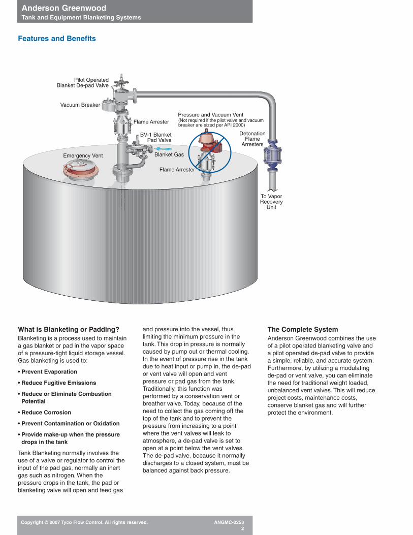
What is Blanketing or Padding?Blanketing is a process used to maintaina gas blanket or pad in the vapor spaceof a pressure-tight liquid storage vessel.Gas blanketing is used to:
• Prevent Evaporation
• Reduce Fugitive Emissions
• Reduce or Eliminate CombustionPotential
• Reduce Corrosion
• Prevent Contamination or Oxidation
• Provide make-up when the pressuredrops in the tank
Tank Blanketing normally involves theuse of a valve or regulator to control theinput of the pad gas, normally an inertgas such as nitrogen. When thepressure drops in the tank, the pad orblanketing valve will open and feed gas
and pressure into the vessel, thuslimiting the minimum pressure in thetank. This drop in pressure is normallycaused by pump out or thermal cooling.In the event of pressure rise in the tankdue to heat input or pump in, the de-pador vent valve will open and ventpressure or pad gas from the tank.Traditionally, this function wasperformed by a conservation vent orbreather valve. Today, because of theneed to collect the gas coming off thetop of the tank and to prevent thepressure from increasing to a pointwhere the vent valves will leak toatmosphere, a de-pad valve is set toopen at a point below the vent valves.The de-pad valve, because it normallydischarges to a closed system, must bebalanced against back pressure.
The Complete SystemAnderson Greenwood combines the useof a pilot operated blanketing valve anda pilot operated de-pad valve to providea simple, reliable, and accurate system.Furthermore, by utilizing a modulating de-pad or vent valve, you can eliminate the need for traditional weight loaded,unbalanced vent valves. This will reduceproject costs, maintenance costs,conserve blanket gas and will furtherprotect the environment.
Emergency Vent Blanket Gas
BV-1 BlanketPad Valve
Flame Arrester
Vacuum Breaker
Pilot OperatedBlanket De-pad Valve
To VaporRecovery
Unit
(Not required if the pilot valve and vacuumbreaker are sized per API 2000)
DetonationFlame
Arresters
Pressure and Vacuum Vent
Flame Arrester
Anderson Greenwood Tank and Equipment Blanketing Systems
Copyright © 2007 Tyco Flow Control. All rights reserved. ANGMC-02533
Features and Benefits
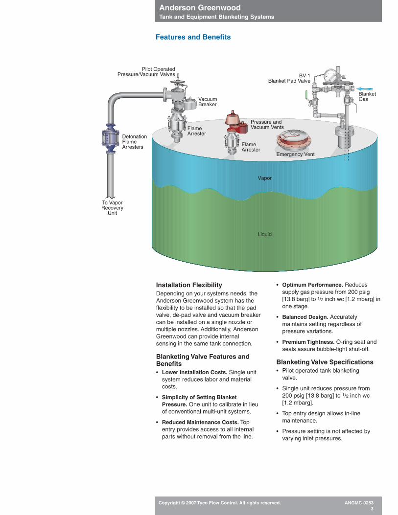
Installation FlexibilityDepending on your systems needs, theAnderson Greenwood system has theflexibility to be installed so that the padvalve, de-pad valve and vacuum breakercan be installed on a single nozzle ormultiple nozzles. Additionally, AndersonGreenwood can provide internalsensing in the same tank connection.
Blanketing Valve Features andBenefits• Lower Installation Costs. Single unit
system reduces labor and materialcosts.
• Simplicity of Setting BlanketPressure. One unit to calibrate in lieuof conventional multi-unit systems.
• Reduced Maintenance Costs. Topentry provides access to all internalparts without removal from the line.
• Optimum Performance. Reduces supply gas pressure from 200 psig [13.8 barg] to 1/2 inch wc [1.2 mbarg] inone stage.
• Balanced Design. Accuratelymaintains setting regardless ofpressure variations.
• Premium Tightness. O-ring seat andseals assure bubble-tight shut-off.
Blanketing Valve Specifications• Pilot operated tank blanketing
valve.
• Single unit reduces pressure from 200 psig [13.8 barg] to 1/2 inch wc[1.2 mbarg].
• Top entry design allows in-line maintenance.
• Pressure setting is not affected by varying inlet pressures.
OUTLET
SENSE
INL
ET
Emergency Vent
Vapor
BV-1Blanket Pad Valve
FlameArrester
Pilot OperatedPressure/Vacuum Valves
DetonationFlameArresters
Pressure andVacuum Vents
Liquid
BlanketGas
To VaporRecovery
Unit
VacuumBreaker
FlameArrester

Anderson Greenwood Tank and Equipment Blanketing Systems
Copyright © 2007 Tyco Flow Control. All rights reserved. ANGMC-02534
Blanketing (Pad Valves) Operation
The conventional method (Figure 1)employs as many as four regulators toreduce high supply pressure to lowblanket pressures, while the AndersonGreenwood system (Figure 2) is the firstvalve that requires only one unit toachieve reduction from 200 psig [13.8barg] to low blanketing pressures.
The Type Y1 Pilot is used with the mainvalve to form a pressure reducing valvecapable of regulating tank pressures from 1/2 inch wc [1.2 mbarg] to 6 psig [0.41 barg]. The pilot will open when thesensed pressure falls below the setpressure. As the pilot opens, the mainvalve dome pressure decreases, andflow through the main valve occurs.When the downstream pressure issatisfied, the sensed pressure acting onthe sense plate will overcome the springforce to close the pilot, the main valvedome pressure increases, and the mainvalve closes.
RA OperationFor small flow requirements, the pilotcan be used by itself as a direct springtank blanketing valve. When used thisway, it is designated a Type RA. Theonly difference in construction is thelocation of the sense and inlet ports. Thesensed pressure acting against thespring force will determine how much, ifany, the pilot is to open.
Y1 OperationUpstream pressure enters the main body and acts upward against the mainvalve diaphragm. Due to a smallunbalanced dome area, the effectivearea above the diaphragm is slightly largerthan below. Shut-off will occur when thedome pressure is equal to the inletpressure. The sleeve/diaphragm retainerassembly is lightly spring loaded toprovide initial closing force when there isno pressure differential across thediaphragm.
The Type Y1 Pilot controls domepressure in response to tank pressure. Areduction in dome pressure allows thesleeve to move upward off the main seat,permitting flow through the valve. Theamount of lift depends on the pressurereduction in the dome. The greater thisreduction, the greater the flow. When thedownstream pressure is satisfied, thesensed pressure acting on the pilotsense plate will overcome the springforce to close the pilot, which in turncloses the valve. No system fluid isvented to the atmosphere.
BV-1 OperationThe diaphragm and sleeve are replacedby a piston in the main valve for morerugged construction. As with the Y1Valve, the pilot controls dome pressure. Areduction in dome pressure allows thepiston to move horizontally off the seat,permitting flow through the valve.Maximum flow is controlled by the cageorifices.
Performance CharacteristicsSet pressure is defined as the point atwhich the valve begins to flow. As thedemand for flow increases, the tankpressure must drop in order for the valveto respond, since a differential pressureis required to create the necessaryforces to operate the valve.
This drop in tank pressure is called ‘droop.’ When the valve is 100 percentopen, the tank pressure must increase for the valve to respond and close. The difference between start to open andclose is called deadband. For the TypeY1 blanketing valve, this deadband is 1 inch wc [2.5 mbarg] at the lowest setpressure. For the Type BV-1 blanketingvalve, this ‘deadband’ is 3/4 inch wc [1.9 mbarg] at the lowest set pressure.Lockup, the rise above set pressure fortotal closure, is less than 0.1 inch wc[0.25 mbarg].
Elastomer SelectionIt is important to specify an elastomer that is compatible with both the supply gas and the product being stored in thetank. Vapors will enter the valve from thedischarge port and sense line. The BV-1comes standard with Fluorosilicone andViton® seat and seals and Teflon®
diaphragm. The RA and Y1 valves comestandard with BUNA-N soft goods. TheBV-1 is available with an internal purgewhich sweeps a small flow rate ofblanket gas back through the sense portand tank connection.
NACE TrimPilot and main valve trims are available for sour gas service in accordance withthe latest edition of NACE MR-01-75.
GOX/LOXThe BV-1 model can be cleaned forGOX and LOX applications.
Note1. Teflon® and Viton® are registered trademarks
of E.I. duPont de Nemours Company.
Pressure Vacuum Vent
Figure 1
1 2
3
4
Conventional Method
Anderson Greenwood Method
Lower Installation CostTo VaporRecovey
Figure 2
Anderson Greenwood Tank and Equipment Blanketing Systems
Copyright © 2007 Tyco Flow Control. All rights reserved. ANGMC-02535
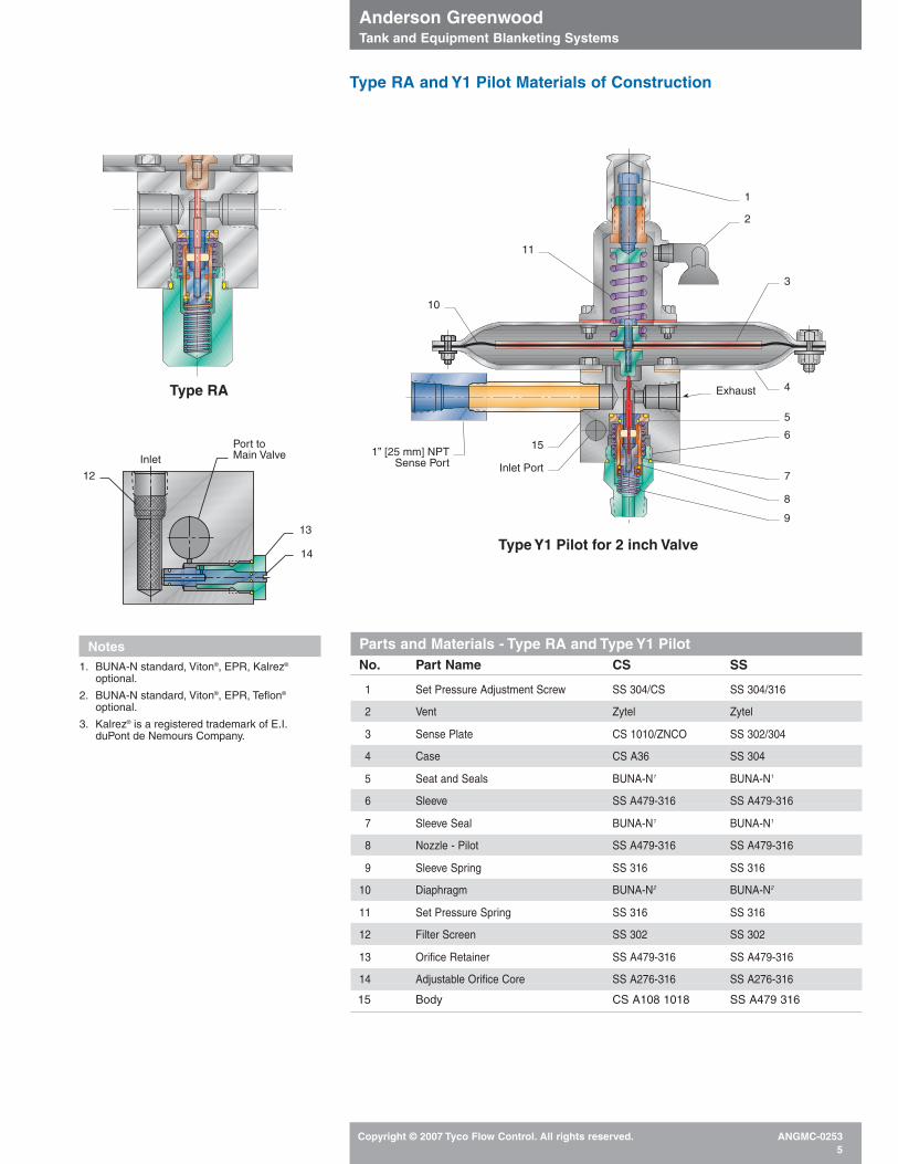
Parts and Materials - Type RA and Type Y1 PilotNo. Part Name CS SS
1 Set Pressure Adjustment Screw SS 304/CS SS 304/316
2 Vent Zytel Zytel
3 Sense Plate CS 1010/ZNCO SS 302/304
4 Case CS A36 SS 304
5 Seat and Seals BUNA-N1 BUNA-N1
6 Sleeve SS A479-316 SS A479-316
7 Sleeve Seal BUNA-N1 BUNA-N1
8 Nozzle - Pilot SS A479-316 SS A479-316
9 Sleeve Spring SS 316 SS 316
10 Diaphragm BUNA-N2 BUNA-N2
11 Set Pressure Spring SS 316 SS 316
12 Filter Screen SS 302 SS 302
13 Orifice Retainer SS A479-316 SS A479-316
14 Adjustable Orifice Core SS A276-316 SS A276-316
15 Body CS A108 1018 SS A479 316
Type RA and Y1 Pilot Materials of Construction
1
2
3
4
5
6
7
8
9
1” [25 mm] NPTSense Port
Exhaust
Inlet Port
10
11
15
Type RA
Type Y1 Pilot for 2 inch Valve
12
14
Inlet
13
Port toMain Valve
Notes1. BUNA-N standard, Viton®, EPR, Kalrez®
optional.
2. BUNA-N standard, Viton®, EPR, Teflon®
optional.
3. Kalrez® is a registered trademark of E.I.duPont de Nemours Company.
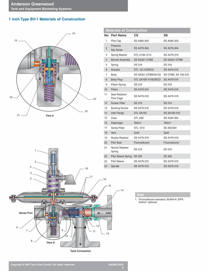
Materials of ConstructionNo. Part Name CS SS
1 Pilot Cap SS A582-303 SS A582-303
Pressure 2
Adj. ScrewSS A276-304 SS A276-304
3 Spring Washer STL A108-1213 SS A479-316
4 Bonnet Assembly SS SA351-CF8M SS SA351-CF8M
5 Spring SS 316 SS 316
6 Actuator STL 12L14/ZNCO SS A479-316
7 Body SS SA351-CF8M/SA105 SS CF8M, SA 182-316
8 Body Plug STL SA108-1018/ZNCO SS A479-316
9 Piston Spring SS 316 SS 316
10 Piston SS A479-316 SS A479-316
11 Seat Retainer/Flow Cage
SS A479-316 SS A479-316
12 Screen Filter SS 316 SS 316
13 Bushing Nozzle SS A479-316 SS A479-316
14 Inlet Flange STL SA105 SS SA182-316
15 Case STL A36 SS A240-304
16 Diaphragm Teflon® Teflon®
17 Sense Plate STL 1010 SS 302/304
18 Vent Zytel Zytel
19 Nozzle Retainer SS A479-316 SS A479-316
20 Pilot Seat Fluorosilicone1 Fluorosilicone1
21 Nozzle Retainer Spring
SS 316 SS 316
22 Pilot Sleeve Spring SS 302 SS 302
23 Pilot Sleeve SS A479-316 SS A479-316
24 Spindle SS A276-316 SS A276-316
Anderson Greenwood Tank and Equipment Blanketing Systems
Copyright © 2007 Tyco Flow Control. All rights reserved. ANGMC-02536
1
2
3
4
5
6
8
18
1716
15
14
7
10
913
12
11
Inlet
Tank Connection
Sense Port
View A
19
20
21
24
23
22
View A
1 inch Type BV-1 Materials of Construction
Note1. Fluorosilicone standard, BUNA-N, EPR,
Kalrez® optional.
Anderson Greenwood Tank and Equipment Blanketing Systems
Copyright © 2007 Tyco Flow Control. All rights reserved. ANGMC-02537
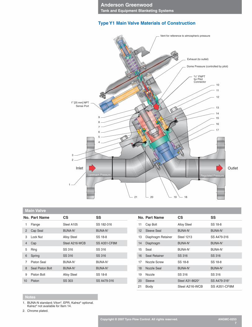
Type Y1 Main Valve Materials of Construction
3/4” FNPTfor PilotConnector
4
11
Regulated PressureUpstream Pressure
Inlet Outlet
14
15
13
2
3
Dome Pressure (controlled by pilot)
Vent for reference to atmospheric pressure
10
12
1” [25 mm] NPTSense Port
Exhaust (to outlet)
1
5
6
7
8
9
16
17
18192021
No. Part Name CS SS
1 Flange Steel A105 SS 182-316
2 Cap Seal BUNA-N1 BUNA-N1
3 Lock Nut Alloy Steel SS 18-8
4 Cap Steel A216-WCB SS A351-CF8M
5 Ring SS 316 SS 316
6 Spring SS 316 SS 316
7 Piston Seal BUNA-N1 BUNA-N1
8 Seal Piston Bolt BUNA-N1 BUNA-N1
9 Piston Bolt Alloy Steel SS 18-8
10 Piston SS 303 SS A479-316
No. Part Name CS SS
11 Cap Bolt Alloy Steel SS 18-8
12 Sleeve Seal BUNA-N1 BUNA-N1
13 Diaphragm Retainer Steel 1213 SS A479-316
14 Diaphragm BUNA-N1 BUNA-N1
15 Seat BUNA-N1 BUNA-N1
16 Seat Retainer SS 316 SS 316
17 Nozzle Screw SS 18-8 SS 18-8
18 Nozzle Seal BUNA-N1 BUNA-N1
19 Nozzle SS 316 SS 316
20 Sleeve Steel A31-86202 SS A479-3162
21 Body Steel A216-WCB SS A351-CF8M
Notes1. BUNA-N standard; Viton®, EPR, Kalrez® optional.
Kalrez® not available for Item 14.
2. Chrome plated.
Main Valve
Anderson Greenwood Tank and Equipment Blanketing Systems
Copyright © 2007 Tyco Flow Control. All rights reserved. ANGMC-02538
OUTLET
SENSE
INL
ET
A
B
D
5.69
C
EOUTLET
SENSE
INL
ET
A
B
C
D
5.69
E
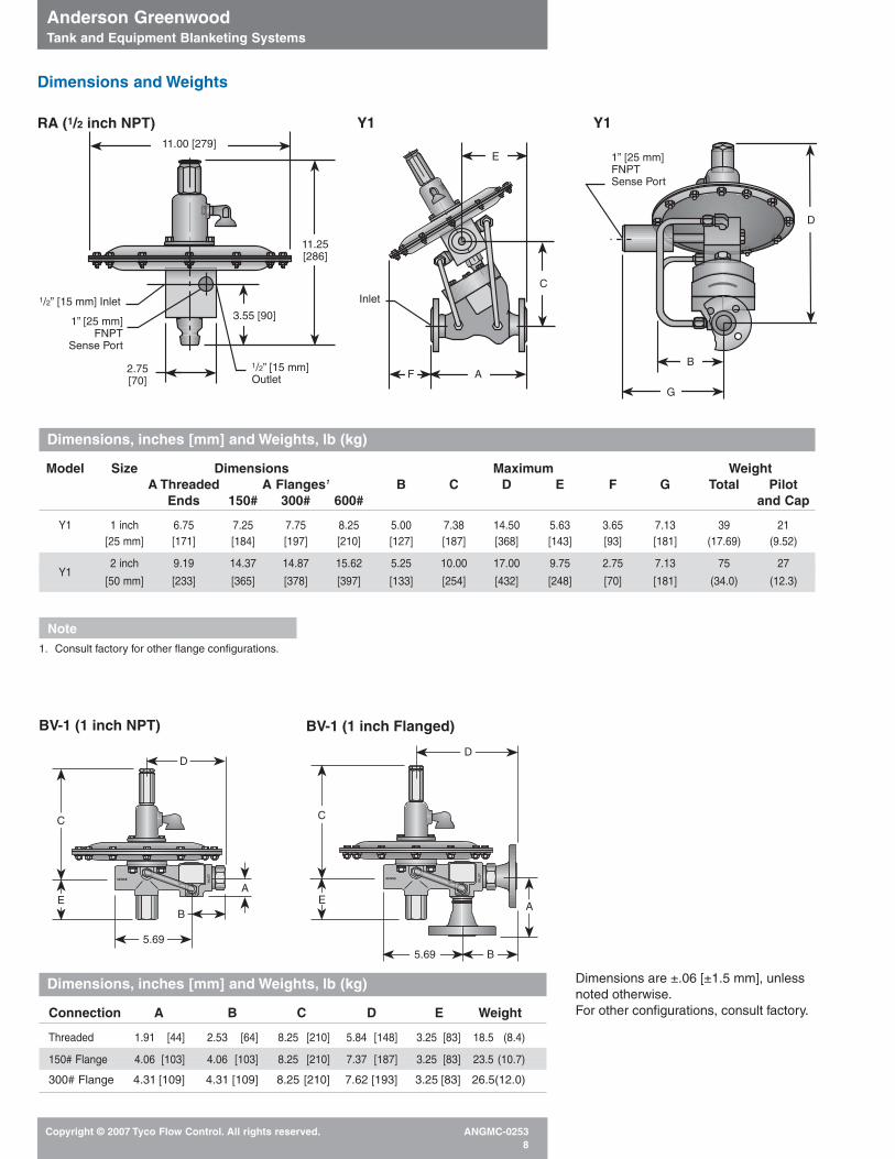
Dimensions are ±.06 [±1.5 mm], unlessnoted otherwise.For other configurations, consult factory.
BV-1 (1 inch NPT) BV-1 (1 inch Flanged)
Dimensions and Weights
1/2” [15 mm] Inlet
1” [25 mm]FNPT
Sense Port
1/2” [15 mm]Outlet
2.75[70]
3.55 [90]
11.25[286]
11.00 [279]1” [25 mm]FNPTSense Port
G
B
D
Inlet
AF
C
E
Dimensions, inches [mm] and Weights, lb (kg)
Model Size Dimensions Maximum WeightA Threaded A Flanges1 B C D E F G Total Pilot
Ends 150# 300# 600# and Cap
Y1 1 inch 6.75 7.25 7.75 8.25 5.00 7.38 14.50 5.63 3.65 7.13 39 21[25 mm] [171] [184] [197] [210] [127] [187] [368] [143] [93] [181] (17.69) (9.52)
2 inch 9.19 14.37 14.87 15.62 5.25 10.00 17.00 9.75 2.75 7.13 75 27Y1
[50 mm] [233] [365] [378] [397] [133] [254] [432] [248] [70] [181] (34.0) (12.3)
Note1. Consult factory for other flange configurations.
Dimensions, inches [mm] and Weights, lb (kg)
Connection A B C D E Weight
Threaded 1.91 [44] 2.53 [64] 8.25 [210] 5.84 [148] 3.25 [83] 18.5 (8.4)
150# Flange 4.06 [103] 4.06 [103] 8.25 [210] 7.37 [187] 3.25 [83] 23.5 (10.7)
300# Flange 4.31 [109] 4.31 [109] 8.25 [210] 7.62 [193] 3.25 [83] 26.5(12.0)
RA (1/2 inch NPT) Y1 Y1
Anderson Greenwood Tank and Equipment Blanketing Systems
Copyright © 2007 Tyco Flow Control. All rights reserved. ANGMC-02539
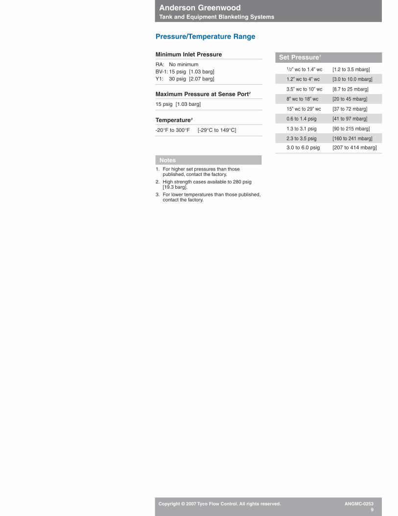
Pressure/Temperature Range
Set Pressure1
1/2” wc to 1.4” wc [1.2 to 3.5 mbarg]
1.2” wc to 4” wc [3.0 to 10.0 mbarg]
3.5” wc to 10” wc [8.7 to 25 mbarg]
8” wc to 18” wc [20 to 45 mbarg]
15” wc to 29” wc [37 to 72 mbarg]
0.6 to 1.4 psig [41 to 97 mbarg]
1.3 to 3.1 psig [90 to 215 mbarg]
2.3 to 3.5 psig [160 to 241 mbarg]
3.0 to 6.0 psig [207 to 414 mbarg]
Minimum Inlet Pressure
RA: No minimumBV-1: 15 psig [1.03 barg]Y1: 30 psig [2.07 barg]
Maximum Pressure at Sense Port2
15 psig [1.03 barg]
Temperature3
-20°F to 300°F [-29°C to 149°C]
Notes1. For higher set pressures than those
published, contact the factory.
2. High strength cases available to 280 psig [19.3 barg].
3. For lower temperatures than those published,contact the factory.
Anderson Greenwood Tank and Equipment Blanketing Systems
Copyright © 2007 Tyco Flow Control. All rights reserved. ANGMC-025310
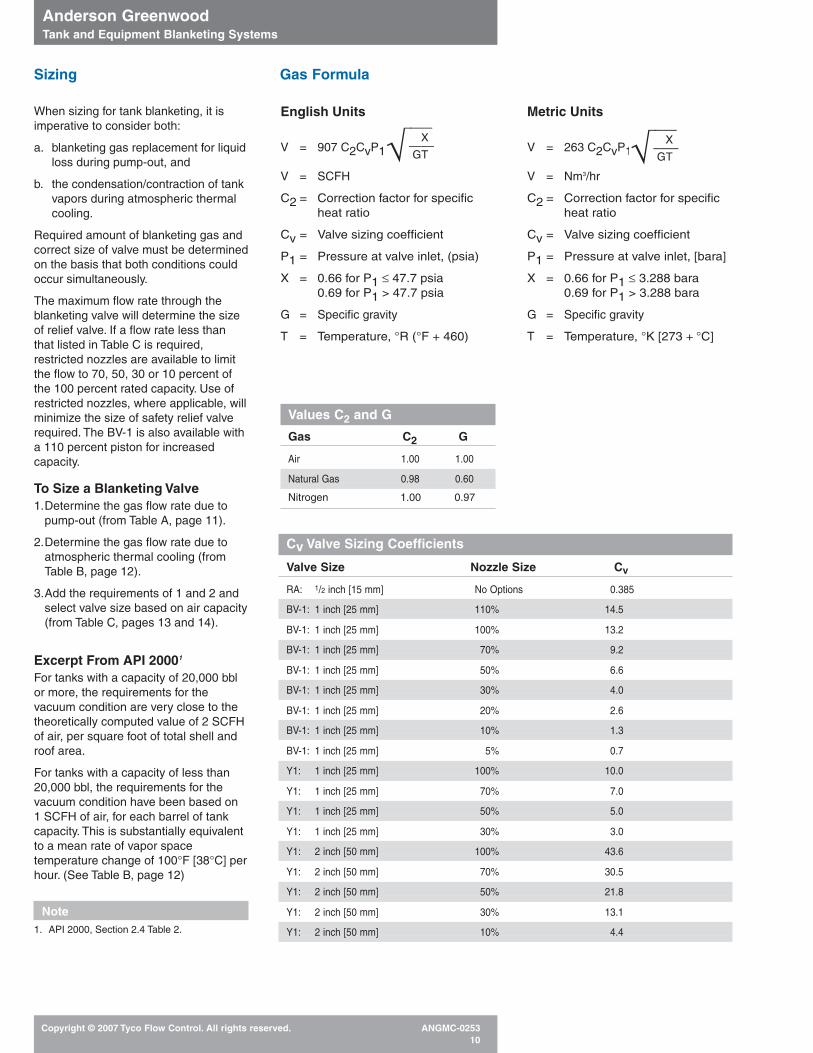
Sizing
When sizing for tank blanketing, it is imperative to consider both:
a. blanketing gas replacement for liquidloss during pump-out, and
b. the condensation/contraction of tankvapors during atmospheric thermalcooling.
Required amount of blanketing gas andcorrect size of valve must be determinedon the basis that both conditions couldoccur simultaneously.
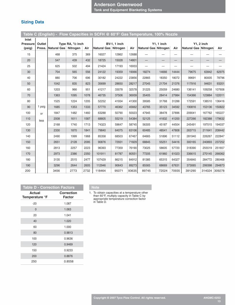
The maximum flow rate through theblanketing valve will determine the sizeof relief valve. If a flow rate less thanthat listed in Table C is required,restricted nozzles are available to limitthe flow to 70, 50, 30 or 10 percent ofthe 100 percent rated capacity. Use ofrestricted nozzles, where applicable, willminimize the size of safety relief valverequired. The BV-1 is also available witha 110 percent piston for increasedcapacity.
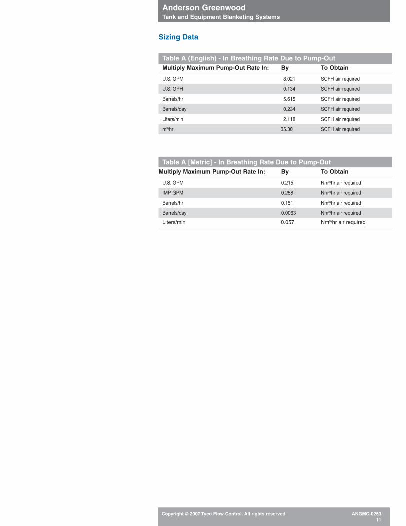
To Size a Blanketing Valve1.Determine the gas flow rate due to
pump-out (from Table A, page 11).
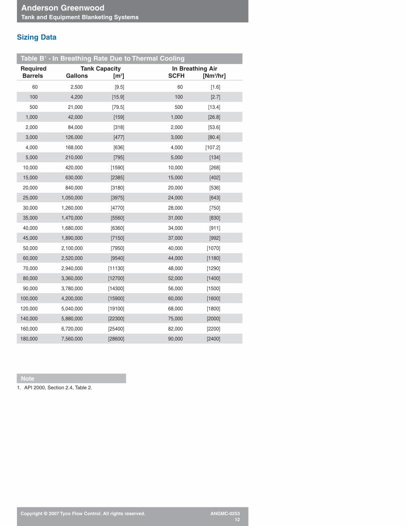
2.Determine the gas flow rate due toatmospheric thermal cooling (fromTable B, page 12).
3.Add the requirements of 1 and 2 andselect valve size based on air capacity(from Table C, pages 13 and 14).
Excerpt From API 20001
For tanks with a capacity of 20,000 bblor more, the requirements for thevacuum condition are very close to thetheoretically computed value of 2 SCFHof air, per square foot of total shell androof area.
For tanks with a capacity of less than20,000 bbl, the requirements for the vacuum condition have been based on 1 SCFH of air, for each barrel of tankcapacity. This is substantially equivalentto a mean rate of vapor spacetemperature change of 100°F [38°C] perhour. (See Table B, page 12)
Note1. API 2000, Section 2.4 Table 2.
English Units
V = 907 C2CvP1
––––– X
–––– √ GT
V = SCFH
C2 = Correction factor for specificheat ratio
Cv = Valve sizing coefficient
P1 = Pressure at valve inlet, (psia)
X = 0.66 for P1 ≤ 47.7 psia0.69 for P1 > 47.7 psia
G = Specific gravity
T = Temperature, °R (°F + 460)
Values C2 and G
Gas C2 G
Air 1.00 1.00
Natural Gas 0.98 0.60
Nitrogen 1.00 0.97
Metric Units
V = 263 C2CvP1
––––– X
–––– √ GT
V = Nm3/hr
C2 = Correction factor for specificheat ratio
Cv = Valve sizing coefficient
P1 = Pressure at valve inlet, [bara]
X = 0.66 for P1 ≤ 3.288 bara0.69 for P1 > 3.288 bara
G = Specific gravity
T = Temperature, °K [273 + °C]
Gas Formula
Cv Valve Sizing Coefficients
Valve Size Nozzle Size Cv
RA: 1/2 inch [15 mm] No Options 0.385
BV-1: 1 inch [25 mm] 110% 14.5
BV-1: 1 inch [25 mm] 100% 13.2
BV-1: 1 inch [25 mm] 70% 9.2
BV-1: 1 inch [25 mm] 50% 6.6
BV-1: 1 inch [25 mm] 30% 4.0
BV-1: 1 inch [25 mm] 20% 2.6
BV-1: 1 inch [25 mm] 10% 1.3
BV-1: 1 inch [25 mm] 5% 0.7
Y1: 1 inch [25 mm] 100% 10.0
Y1: 1 inch [25 mm] 70% 7.0
Y1: 1 inch [25 mm] 50% 5.0
Y1: 1 inch [25 mm] 30% 3.0
Y1: 2 inch [50 mm] 100% 43.6
Y1: 2 inch [50 mm] 70% 30.5
Y1: 2 inch [50 mm] 50% 21.8
Y1: 2 inch [50 mm] 30% 13.1
Y1: 2 inch [50 mm] 10% 4.4
Anderson Greenwood Tank and Equipment Blanketing Systems
Copyright © 2007 Tyco Flow Control. All rights reserved. ANGMC-025311
Sizing Data
Table A (English) - In Breathing Rate Due to Pump-OutMultiply Maximum Pump-Out Rate In: By To Obtain
U.S. GPM 8.021 SCFH air required
U.S. GPH 0.134 SCFH air required
Barrels/hr 5.615 SCFH air required
Barrels/day 0.234 SCFH air required
Liters/min 2.118 SCFH air required
m3/hr 35.30 SCFH air required
Table A [Metric] - In Breathing Rate Due to Pump-OutMultiply Maximum Pump-Out Rate In: By To Obtain
U.S. GPM 0.215 Nm3/hr air required
IMP GPM 0.258 Nm3/hr air required
Barrels/hr 0.151 Nm3/hr air required
Barrels/day 0.0063 Nm3/hr air required
Liters/min 0.057 Nm3/hr air required
Anderson Greenwood Tank and Equipment Blanketing Systems
Copyright © 2007 Tyco Flow Control. All rights reserved. ANGMC-025312
Sizing Data
Required Tank Capacity In Breathing AirBarrels Gallons [m3] SCFH [Nm3/hr]
60 2,500 [9.5] 60 [1.6]
100 4,200 [15.9] 100 [2.7]
500 21,000 [79.5] 500 [13.4]
1,000 42,000 [159] 1,000 [26.8]
2,000 84,000 [318] 2,000 [53.6]
3,000 126,000 [477] 3,000 [80.4]
4,000 168,000 [636] 4,000 [107.2]
5,000 210,000 [795] 5,000 [134]
10,000 420,000 [1590] 10,000 [268]
15,000 630,000 [2385] 15,000 [402]
20,000 840,000 [3180] 20,000 [536]
25,000 1,050,000 [3975] 24,000 [643]
30,000 1,260,000 [4770] 28,000 [750]
35,000 1,470,000 [5560] 31,000 [830]
40,000 1,680,000 [6360] 34,000 [911]
45,000 1,890,000 [7150] 37,000 [992]
50,000 2,100,000 [7950] 40,000 [1070]
60,000 2,520,000 [9540] 44,000 [1180]
70,000 2,940,000 [11130] 48,000 [1290]
80,000 3,360,000 [12700] 52,000 [1400]
90,000 3,780,000 [14300] 56,000 [1500]
100,000 4,200,000 [15900] 60,000 [1600]
120,000 5,040,000 [19100] 68,000 [1800]
140,000 5,880,000 [22300] 75,000 [2000]
160,000 6,720,000 [25400] 82,000 [2200]
180,000 7,560,000 [28600] 90,000 [2400]
Table B1 - In Breathing Rate Due to Thermal Cooling
Note1. API 2000, Section 2.4, Table 2.
Anderson Greenwood Tank and Equipment Blanketing Systems
Copyright © 2007 Tyco Flow Control. All rights reserved. ANGMC-025313
InletPressure Outlet Type RA, 1/2 inch BV-1, 1 inch Y1, 1 inch Y1, 2 inch
(psig) Press. Natural Gas Nitrogen Air Natural Gas Nitrogen Air Natural Gas Nitrogen Air Natural Gas Nitrogen Air
15 468 375 369 16027 12862 12688 — — — — — —
20 547 439 432 18725 15028 14801 — — — — — —
25 625 502 494 21424 17193 16933 — — — — — —
30 704 565 556 24122 19359 19066 18274 14666 14444 79675 63942 62975
40 880 706 696 30182 24222 23856 22865 18350 18072 99691 80005 78796
50 1042 835 823 35699 28650 28217 27045 21704 21376 117916 94631 93201
60 1203 966 951 41217 33078 32578 31225 25059 24680 136141 109258 107606
70 1363 1095 1078 46735 37506 36939 35405 28414 27984 154366 123884 122011
80 1525 1224 1205 52252 41934 41300 39585 31768 31288 172591 138510 136416
90 1685 1353 1333 57770 46362 45662 43765 35123 34592 190816 153136 150822
100 1847 1482 1460 63288 50790 50023 47945 38478 37896 209041 167762 165227
110 2008 1611 1587 68805 55219 54384 52125 41832 41200 227266 182388 179632
120 2168 1740 1713 74323 59647 58745 56305 45187 44504 245491 197015 194037
130 2330 1870 1841 79840 64075 63106 60485 48541 47808 263715 211641 208442
140 2490 1999 1968 85358 68503 67467 64665 51896 51112 281940 226267 222847
150 2651 2128 2095 90876 72931 71829 68845 55251 54416 300165 240893 237252
160 2813 2257 2223 96393 77359 76190 73025 58605 57720 318390 255519 251657
170 2973 2386 2350 101911 81787 80551 77205 61960 61023 336615 270145 266062
180 3135 2515 2477 107429 86215 84912 81385 65315 64327 354840 284772 280468
190 3296 2644 2605 112946 90643 89273 85565 68669 67631 373065 299398 294873
200 3456 2773 2732 118464 95071 93635 89745 72024 70935 391290 314024 309278
Sizing Data
Table D - Correction FactorsActual Correction
Temperature °F Factor
-20 1.087
0 1.063
20 1.041
40 1.020
60 1.000
80 0.9813
100 0.9636
120 0.9469
150 0.9233
200 0.8876
250 0.8558
Note1. To obtain capacities at a temperature other
than 60°F, multiply capacity in Table C by appropriate temperature correction factor in Table D.
1 psig
or
less
Table C (English) - Flow Capacities in SCFH @ 60°F1 Gas Temperature, 100% Nozzle
Anderson Greenwood Tank and Equipment Blanketing Systems
Copyright © 2007 Tyco Flow Control. All rights reserved. ANGMC-025314
Sizing Data
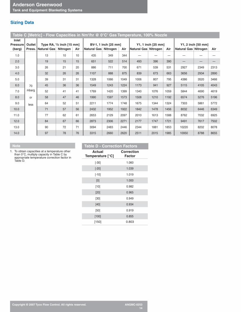
InletPressure Outlet Type RA, 1/2 inch [15 mm] BV-1, 1 inch [25 mm] Y1, 1 inch [25 mm] Y1, 2 inch [50 mm]
(barg) Press. Natural Gas Nitrogen Air Natural Gas Nitrogen Air Natural Gas Nitrogen Air Natural Gas Nitrogen Air
1.0 13 10 10 435 349 344 — — — — — —
2.0 19 15 15 651 522 514 493 396 390 — — —
3.0 26 21 20 886 711 700 671 539 531 2927 2349 2313
4.0 32 26 26 1107 888 875 839 673 663 3656 2934 2890
5.0 39 31 31 1328 1066 1049 1006 807 795 4386 3520 3466
6.0 45 36 36 1549 1243 1224 1173 941 927 5115 4105 4043
7.0 52 41 41 1769 1420 1399 1340 1076 1059 5844 4690 4619
8.0 58 47 46 1990 1597 1573 1508 1210 1192 6574 5276 5196
9.0 64 52 51 2211 1774 1748 1675 1344 1324 7303 5861 5772
10.0 71 57 56 2432 1952 1922 1842 1478 1456 8032 6446 6349
11.0 77 62 61 2653 2129 2097 2010 1613 1588 8762 7032 6925
12.0 84 67 66 2873 2306 2271 2177 1747 1721 9491 7617 7502
13.0 90 72 71 3094 2483 2446 2344 1881 1853 10220 8202 8078
14.0 97 78 76 3315 2660 2620 2511 2015 1985 10950 8788 8655
Note1. To obtain capacities at a temperature other
than 0°C, multiply capacity in Table C byappropriate temperature correction factor inTable D.
70 mbarg
or
less
Table D - Correction FactorsActual Correction
Temperature [°C] Factor
[-30] 1.060
[-20] 1.039
[-10] 1.019
[0] 1.000
[10] 0.982
[20] 0.965
[30] 0.949
[40] 0.934
[50] 0.919
[100] 0.855
[150] 0.803
Table C [Metric] - Flow Capacities in Nm3/hr @ 0°C1 Gas Temperature, 100% Nozzle
Anderson Greenwood Tank and Equipment Blanketing Systems
Copyright © 2007 Tyco Flow Control. All rights reserved. ANGMC-025315
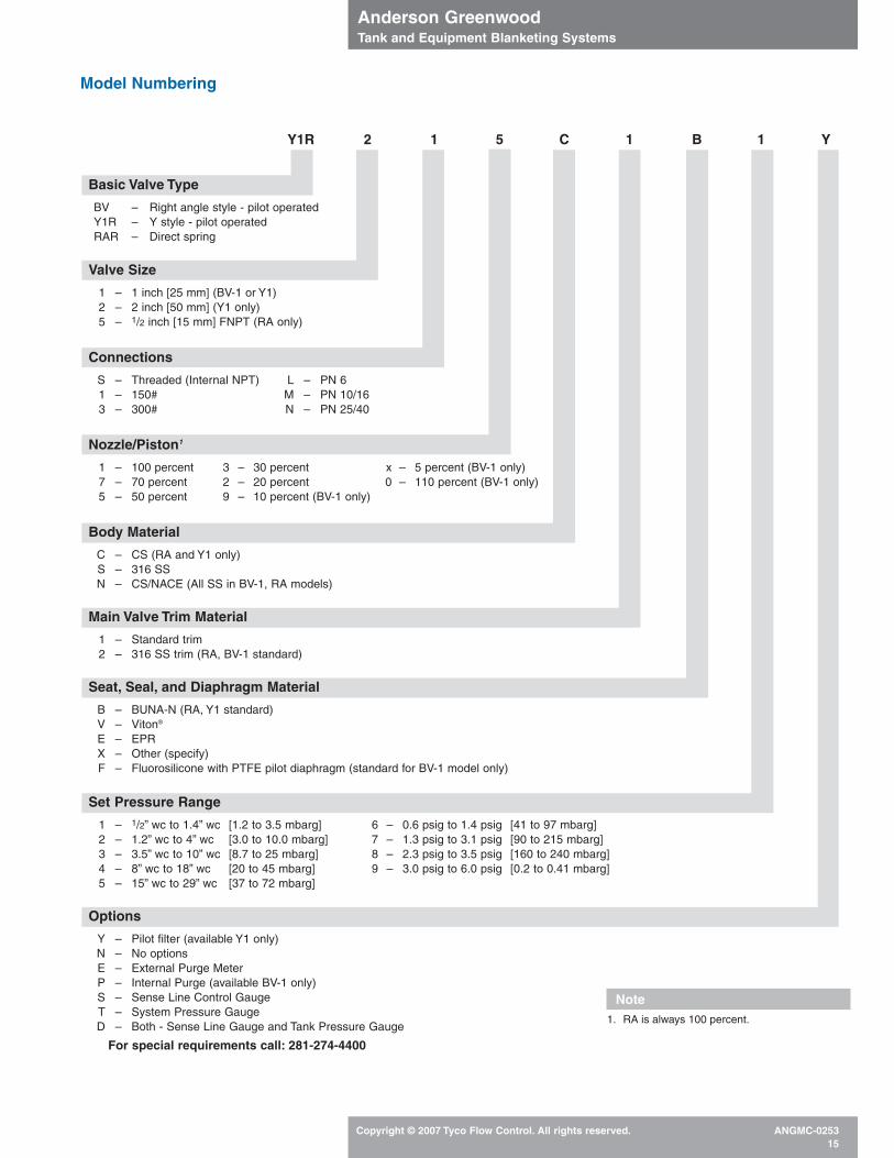
Model Numbering
Y1R 2 1 5 C 1 B 1 Y
Basic Valve Type
BV – Right angle style - pilot operatedY1R – Y style - pilot operatedRAR – Direct spring
Valve Size
1 – 1 inch [25 mm] (BV-1 or Y1)2 – 2 inch [50 mm] (Y1 only)5 – 1/2 inch [15 mm] FNPT (RA only)
Connections
S – Threaded (Internal NPT) L – PN 61 – 150# M – PN 10/16 3 – 300# N – PN 25/40
Nozzle/Piston1
1 – 100 percent 3 – 30 percent x – 5 percent (BV-1 only)7 – 70 percent 2 – 20 percent 0 – 110 percent (BV-1 only)5 – 50 percent 9 – 10 percent (BV-1 only)
Body Material
C – CS (RA and Y1 only)S – 316 SSN – CS/NACE (All SS in BV-1, RA models)
Main Valve Trim Material
1 – Standard trim2 – 316 SS trim (RA, BV-1 standard)
Seat, Seal, and Diaphragm Material
B – BUNA-N (RA, Y1 standard)V – Viton®
E – EPRX – Other (specify)F – Fluorosilicone with PTFE pilot diaphragm (standard for BV-1 model only)
Set Pressure Range
1 – 1/2” wc to 1.4” wc [1.2 to 3.5 mbarg] 6 – 0.6 psig to 1.4 psig [41 to 97 mbarg]2 – 1.2” wc to 4” wc [3.0 to 10.0 mbarg] 7 – 1.3 psig to 3.1 psig [90 to 215 mbarg]3 – 3.5” wc to 10” wc [8.7 to 25 mbarg] 8 – 2.3 psig to 3.5 psig [160 to 240 mbarg]4 – 8” wc to 18” wc [20 to 45 mbarg] 9 – 3.0 psig to 6.0 psig [0.2 to 0.41 mbarg]5 – 15” wc to 29” wc [37 to 72 mbarg]
Options
Y – Pilot filter (available Y1 only)N – No optionsE – External Purge MeterP – Internal Purge (available BV-1 only)S – Sense Line Control GaugeT – System Pressure GaugeD – Both - Sense Line Gauge and Tank Pressure Gauge
For special requirements call: 281-274-4400
Note1. RA is always 100 percent.

Anderson Greenwood Tank and Equipment Blanketing Systems
Copyright © 20047 Tyco Flow Control. All rights reserved. ANGMC-025316
Tyco Flow Control (TFC) provides the information herein in good faith but makes no representation as to its comprehensiveness or accuracy. This data sheet is intended only as a guide to TFC products and services.Individuals using this data sheet must exercise their independent judgment in evaluating product selection and determining product appropriateness for their particular purpose and system requirements. TFC MAKESNO REPRESENTATIONS OR WARRANTIES, EITHER EXPRESS OR IMPLIED, INCLUDING WITHOUT LIMITATION ANY WARRANTIES OF MERCHANTABILITY OR FITNESS FOR A PARTICULAR PURPOSE WITHRESPECT TO THE INFORMATION SET FORTH HEREIN OR THE PRODUCT(S) TO WHICH THE INFORMATION REFERS. ACCORDINGLY, TFC WILL NOT BE RESPONSIBLE FOR DAMAGES (OF ANY KIND ORNATURE, INCLUDING INCIDENTAL, INDIRECT, OR CONSEQUENTIAL DAMAGES) RESULTING FROM THE USE OF OR RELIANCE UPON THIS INFORMATION. Patents and Patents Pending in the U.S. and foreign countries. Tyco reserves the right to change product designs and specifications without notice.
www.tycoflowcontrol.com
Stafford Facility Phone: 281-274-4400
Related Documents