SYNTHESIS AND APPLICATIONS OF ONE- AND TWO-DIMENSIONAL POLYMER–CARBON NANOMATERIAL COMPOSITES by Wanji Seo B.S., The Ohio State University, 2007 Submitted to the Graduate Faculty of the Dietrich School of Arts and Sciences in partial fulfillment of the requirements for the degree of Doctor of Philosophy University of Pittsburgh 2016

Welcome message from author
This document is posted to help you gain knowledge. Please leave a comment to let me know what you think about it! Share it to your friends and learn new things together.
Transcript
i
SYNTHESIS AND APPLICATIONS OF
ONE- AND TWO-DIMENSIONAL POLYMER–CARBON NANOMATERIAL
COMPOSITES
by
Wanji Seo
B.S., The Ohio State University, 2007
Submitted to the Graduate Faculty of the
Dietrich School of Arts and Sciences in partial fulfillment
of the requirements for the degree of
Doctor of Philosophy
University of Pittsburgh
2016
ii
UNIVERSITY OF PITTSBURGH
DIETRICH SCHOOL OF ARTS AND SCIENCES
This dissertation was presented
by
Wanji Seo
It was defended on
Aug 15th, 2016
and approved by
Prof., Tara Y. Meyer, Associate Professor, Department of Chemistry
Prof., W. Seth Horne, Associate Professor, Department of Chemistry
Prof., Lei Li, Assistant Professor, Department of Chemical and Petroleum Engineering
Thesis Director/Dissertation Advisor: Prof., Alexander Star, Professor, Department of
Chemistry
iii
Copyright © by Wanji Seo
2016
SYNTHESIS AND APPLICATIONS OF ONE- AND TWO-DIMENSIONAL
POLYMER–CARBON NANOMATERIAL COMPOSITES
Wanji Seo, PhD
University of Pittsburgh, 2016
iv
SYNTHESIS AND APPLICATIONS OF ONE- AND TWO-DIMENSIONAL
POLYMER–CARBON NANOMATERIAL COMPOSITES
Wanji Seo, PhD
University of Pittsburgh, 2016
This dissertation describes the synthesis of polymer and carbon nanomaterial composites and
their applications in drug delivery, chemical sensing, and catalytic oxidative patterning. The first
part studies polyethylene glycol functionalized oxidized single-walled carbon nanotubes (PL-
PEG/ox-SWCNT) as a drug nanocarrier to prolong the circulation of two mitochondria targeting
radiomitigators TPP-IOA and XJB-5-131. In in vivo tests with mice exposed to a single total
body irradiation of 9.25 Gy, the PL-PEG/ox-SWCNT nanocarrier prolongs the circulation of
TPP-IOA without developing apparent toxicity and exhibits radiation mitigating effects, slightly
better than that of free TPP-IOA. The in vivo drug effect of the XJB-5-131 conjugate is
inconclusive. The stability of Doxorubicin-loaded PL-PEG/ox-SWCNT is investigated under
oxidative bursts that occur in neutrophils and macrophages. Myeloperoxidase-catalyzed and
peroxynitrite-mediated oxidations of the drug conjugate are studied ex vivo, and the in vitro tests
in B16 melanoma cells and tumor-activated myeloid cells are conducted. Both ex vivo and in
vitro results indicate that the nanocarrier protects Doxorubicin from the oxidative degradation.
The second part of the dissertation discusses the synthesis and applications of two-
dimensional polymers. A novel crystalline polybenzobisimidazole-based two-dimensional
supramolecular polymer (2DSP-PBBI) is synthesized by condensation/precipitation
polymerization under solvothermal conditions. The surface morphology of 2DSP-PBBI is
v
analyzed with electron and atomic force microscopy, revealing planar surfaces formed by
hydrogen bonding. An iron(III)-coordinated porphyrin-based covalent organic framework (Fe-
DhaTph-COF) is synthesized for the fabrication of oxidatively patterned graphite in the presence
of H2O2 and/or NaOCl. The vertical channel created by patterning is ~3 nm in depth, and liquid-
exfoliation of the patterned graphite provides few-layer porous graphene. Although the shape
and size of the pores are not uniform, this study demonstrates that metallated COFs can be
utilized as surface catalysts and master templates for patterning.
vi
TABLE OF CONTENTS
1.0 INTRODUCTION…………………………………………………………………….1
1.1 CARBON NANOMATERIALS.………………………………………………..3
1.1.1 One-dimensional carbon nanotubes ............................................................ 5
1.1.2 Two-dimensional graphene .......................................................................... 6
1.2.3 Characterization methods ............................................................................ 8
1.2 POLYMER–CARBON NANOMATERIAL COMPOSITES….……………..12
1.2.1 Covalent and noncovalent chemistry of carbon nanomaterials ............. 12
1.2.2 Applications of polymer–carbon nanomaterial composites…………16
1.2.2.1 Polymer reinforcement……………………………………….16
1.2.2.2 Drug delivery…………………………………………………..17
1.2.2.3 Chemical sensing………………………………………………18
1.3 OXIDATION OF CARBON NANOMATERIALS.………………………20
1.3.1 Oxidation in biological systems...………………..……………….……...21
1.3.1.1 Enzyme-catalyzed oxidation.…………………………………..21
1.3.1.2 Peroxynitrite-mediated oxidation..…………………………….23
1.3.1.3 Oxidative biodegradation of carbon nanomaterials………….25
1.3.2 Catalytic oxidation of nonbiological systems….………………….……..27
1.3.2.1 Fenton-like oxidation………...………………………………….28
vii
1.3.2.2 Synthetic iron porphyrin catalysts.……………………..30
1.3.2.3 Nonbiological catalytic oxidation of carbon nanomaterials... 31
2.0 SYNTHESIS OF POLYMER–CARBON NANOTUBE COMPOSITE FOR DRUG
DELIVERY....……………………………………………………………………………..32
2.1 CHAPTER PREFACE.......……………………………………………………….32
2.2 INTRODUCTION.………………… …………………………………….33
2.2.1 Drug nanocarriers and carbon nanotubes ................................................ 35
2.2.2 Functionalization with phospholipid–polyethylene glycol……………38
2.2.3 Mitochondria targeting drugs.................................................................... 40
2.3 EXPERIMENTAL ................................................................................................... 41
2.3.1 Synthesis of drug carrier (PL-PEG/ox-SWCNT) .................................... 41
2.3.2 Preparation of the TPP-IOA conjugate (TPP-IOA-SWCNT) ................ 41
2.3.3 Preparation of the XJB-5-131 conjugate (XJB-SWCNT) ....................... 42
2.3.4 In vivo experiments of the TPP-IOA conjugate (TPP-IOA-SWCNT) ... 43
2.3.5 In vivo experiments of the XJB-5-131 conjugate (XJB-SWCNT) .......... 43
2.4 RESULTS AND DISCUSSION ................................................................................ 45
2.4.1 Charaterization of PL-PEG/ox-SWCNT .................................................. 45
2.4.2 Characterization of the TPP-IOA conjugate ............................................ 46
2.4.3 Characterization of the XJB-5-131 conjugate .......................................... 47
2.4.4 In vivo results of the TPP-IOA conjugate……………………..………....49
2.4.5 In vivo results of the XJB-5-131 conjugate ............................................... 51
2.5 CONCLUSION .......................................................................................................... 53
viii
2.6 SUPPORTING INFORMATION ............................................................................ 54
3.0 OXIDATIVE BIODEGRADATION STUDIES OF DOXORUBICIN-SINGLE
WALLED NANOTUBE DRUG CONJUGATE ............................................................. 59
3.1 CHAPTER PREFACE ............................................................................................ 59
3.2 INTRODUCTION ................................................................................................... 60
3.2.1 Safety and toxicity of drug nanocarriers………………………………62
3.2.2 Innate immune responses to nanocarriers and pharmacokinetic
implications………………………………..….………………………….63
3.2.3 Doxorubicin conjugates with PL-PEG/ox-SWCNT composites….……..65
3.3 EXPERIMENTAL ................................................................................................... 68
3.3.1 Preparation of the Doxorubicin conjugate (DOX-SWCNT) ................... 68
3.3.2 Ex vivo oxidation of the Doxorubicin conjugate ...................................... 68
3.3.2.1 Myeloperoxidase-catalyzed degradation.……………………..68
3.3.2.2 Peroxynitrite-mediated degradation…………………………..69
3.3.3 Zeta potential of MPO and DOX-SWCNT............................................... 70
3.3.4 In vitro oxidation of Doxorubicin conjugate..……………………70
3.4 RESULTS AND DISCUSSION ............................................................................... 73
3.4.1 Charaterization of Doxorubicin and nanocarrier.................................... 73
3.4.2 Ex vivo oxidative degradation of Doxorubicin and nanocarrier ............ 75
3.4.2.1 Myeloperoxidase-catalyzed degradation……………………..75
3.4.2.2 Peroxynitrite-mediated degradation.………………………….81
3.4.2.3 Binding interactions with myeloperoxidase………………….83
ix
3.4.3 In vitro study of Doxorubicin nanoconjugate in myeloid cells ................ 85
3.5 CONCLUSION ......................................................................................................... 88
3.6 SUPPORTING INFORMATION ........................................................................... 89
4.0 SYNTHESIS AND CHARACTERIZATION OF TWO-DIMENSIONAL
SUPRAMOLECULAR POLYMERS. .… . .………………………..……….99
4.1 CHAPTER PREFACE ............................................................................................ 99
4.2 INTRODUCTION ................................................................................................. 100
4.2.1 Two-dimensional polymers.………………………………………………103
4.2.2 Synthetic approaches for two-dimensional polymers…………………104
4.2.3 Polybenzimidazole-based polymers…………………..…………………106
4.3 EXPERIMENTAL ................................................................................................ 108
4.3.1 Synthesis of SP-PBBI and 2DSP-PBBI.……………….…………………108
4.3.2 Instrumentation.……………………………………..…………………108
4.3.3 Titration of metal–polybenzobisimidazole complexation .……………109
4.3.4 Fabrication of porous graphene by Fenton-like oxidation….…………110
4.4 RESULTS AND DISCUSSION ........................................................................... 112
4.4.1 Characterization of SP-PBBI......…………………………..…..………112
4.4.2 Surface morphology of 2DSP-PBBI………………….…………………115
4.4.3 Optical properties of 2DSP-PBBI…………………………..……………119
4.4.4 Cu(II)–PBBI complexation and Fenton-like catalyst……...…………121
4.5 CONCLUSION ..................................................................................................... 124
4.6 SUPPORTING INFORMATION ....................................................................... 125
x
5.0 COVALENT ORGANIC FRAMEWORKS AS SURFACE CATALYSTS FOR
PATTEREND GRAPHENE......……………………………………………………...136
5.1 CHAPTER PREFACE ......................................................................................... 136
5.2 INTRODUCTION ................................................................................................ 137
5.2.1 Metallated covalent organic frameworks……………………..………138
5.2.2 On-surface synthesis of covalent organic frameworks.........………140
5.2.3 Fabrication of porous graphene………………..……………..………143
5.3 EXPERIMENTAL .............................................................................................. 145
5.3.1 Synthesis and characterization of Fe-DhaTph-COF…………………145
5.3.2 Fabrication of porous graphene……….………………………..………146
5.4 RESULTS AND DISCUSSION .......................................................................... 148
5.4.1 Characterization of Fe-DhaTph-COF……………………..…..………148
5.4.2 Oxidative conditions for patterning graphite…………….. ..…….…150
5.4.3 Characterization of patterned graphite with FTIR and Raman
spectroscopy..…………………………………………………...………155
5.5 CONCLUSION .................................................................................................... 157
5.6 SUPPORTING INFORMATION ...................................................................... 158
BIBLIOGRAPHY ..................................................................................................................... 168
xi
LIST OF TABLES
Chapter 2
Table 2.1 Raman characteristic peaks and the ratio of D to G…...…………………………45
Table 2.2 Identification of functional groups by FTIR analysis…………..………………...56
Chapter 3
Table 3.1 Zeta potential changes upon sequential addition of each component at pH 7.4..84
Chapter 5
Table 5.1 Raman ID/IG values of oxidatively patterned HOPG with Fe-DhaTph-COF.…156
xii
LIST OF FIGURES
Chapter 1
Figure 1.1 Carbon allotropes based on dimensionality……………………………………….4
Figure 1.2 Physical properties of single-walled carbon nanotubes…………………………..6
Figure 1.3 UV-Vis-NIR and Raman Spectroscopy..…………………………………………11
Figure 1.4 Covalent functionalization of SWCNTs………………………………………….15
Figure 1.5 Scheme of classic peroxidase cycle activated by H2O2…………………………..23
Figure 1.6 Scheme of peroxynitrite formation……………………………………….……... 24
Chapter 2
Figure 2.1 Representation of nanocarrier and drugs….…………………………………….34
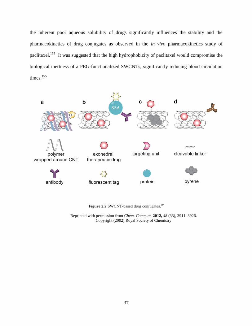
Figure 2.2 SWCNT-based drug conjugates.………………………………………………….37
Figure 2.3 Topology of polyethylene glycol..……………………………………………….39
Figure 2.4 Raman spectroscopy of pristine HiPco SWCNT and ox-SWCNT……………...45
Figure 2.5 TEM micrographs………………………………………………………………….46
Figure 2.6 TEM micrograph and zeta potential of TPP-IOA-SWCNT…………………….47
Figure 2.7 TEM micrograph and zeta potential of XJB-SWCNT…………………………..48
Figure 2.8 In vivo results of TPP-IOA-SWCNT……………………………………………..50
Figure 2.9 In vivo results of XJB-SWCNT………………………………………………….52
xiii
Figure 2.10 MALDI mass spectrum of PL-PEG……………………………………………..55
Figure 2.11 IR absorption spectrum of ox-SWCNT……………………………………..56
Figure 2.12 X-ray photoelectron spectroscopy of ox-SWCNT……………………………...58
Chapter 3
Figure 3.1 DOX-SWCNT and major oxidation routes activated by the immune system…61
Figure 3.2 In vivo biocompatibility, clearance, and cytotoxicity of nanoparticles…………65
Figure 3.3 Characterization of DOX-SWCNT……………………………………………….74
Figure 3.4 MPO-catalyzed oxidative degradation of DOX-SWCNT……………………….76
Figure 3.5 MPO-catalyzed oxidative Degradation of free DOX and DOX-SWCNT…...…78
Figure 3.6 Degradation products of DOX…………………………………………………….80
Figure 3.7 Peroxynitrite-mediated degradation……………………………………………...82
Figure 3.8 Zeta potential titration of the DOX-SWCNT with MPO……………………….84
Figure 3.9 Cytotoxic effects of free DOX vs. DOX-SWCNT in B16 melanoma cells and
bone marrow-derived, tumor-activated MDSC…………………...…………....87
Figure 3.10 UV-Vis titration of PL-PEG/ox-SWCNT with DOX………………………….90
Figure 3.11 Zeta potential titration of PL-PEG/ox-SWCNT with DOX…………………....91
Figure 3.12 1H NMR spectrum of free DOX at 0 h……………………………………..……92
Figure 3.13 1H NMR spectrum of free DOX (−MPO/−H2O2) after 32 h….………………..93
Figure 3.14 LC/MS chromatograms and mass spectra of the control sample…..…………94
Figure 3.15 Peroxynitrite-mediated degradation of free DOX (UV-Vis-NIR).…………….95
Figure 3.16 Ex vivo pH-dependent drug release from DOX-SWCNT…………………….96
Figure 3.17 In vitro DOX release in cell medium…..………………………………………97
xiv
Figure 3.18 MDSC abrogated cytotoxic/cytostatic effect……………………………………98
Chapter 4
Figure 4.1 Synthetic scheme of COF-Salophen and 2DSP-PBBI…………………………102
Figure 4.2 Mechanistic models of supramolecular polymerization…….………………….106
Figure 4.3 Monoclinic and triclinic structures of PIPD..…………….…………………….107
Figure 4.4 Characterization of SP-PBBI (FTIR and 13
C CP MAS NMR).……………113
Figure 4.5 Characterization of SP-PBBI (PXRD) ……....……………..…………………...115
Figure 4.6 TEM and AFM micrographs of 2DSP-PBBI……...…………………………....118
Figure 4.7 TEM micrographs of PBBI-2 and PBBI-170…...……………………………...119
Figure 4.8 Titration of 2DSP-PBBI with Co(II)……………………………………………121
Figure 4.9 Fenton-like catalytic system of Cu(II)/Cu(I) and oxidative degradation of
HOPG...……………………………………..……………………………………123
Figure 4.10 Synthetic Scheme of model compound 4……………………………………... 128
Figure 4.11 FTIR spectra…………….………………………………………………………129
Figure 4.12 NMR spectra…………………………………………………………………….130
Figure 4.13 PXRD of PBBI-170……….…………………………………………………….132
Figure 4.14 TGA trace of SP-PBBI…….……………………………………………………133
Figure 4.15 TEM micrographs of 2DSP-PBBI……………………………………………..133
Figure 4.16 AFM micrographs of 2DSP-PBBI……………………………………….…….134
Figure 4.17 UV-Vis absorption spectra of 2DSP-PBBI and the monomers………………135
Figure 4.18 Energy band gap and conductivity of 2DSP-PBBI…...………………………135
xv
Chapter 5
Figure 5.1 Illustration of fabricating porous graphene……….……………………………138
Figure 5.2 Metallated COF catalysts.…………………..……………………………………140
Figure 5.3 COF-5 grown on graphene….……………………..…………………………….142
Figure 5.4 Patterned porous graphene..…...………………………………………………144
Figure 5.5 AFM micrographs of COF and metallated COFs………………………….149
Figure 5.6 TEM and AFM micrographs….……………………….………………………..154
Figure 5.7 FTIR and Raman spectroscopy.……………………………………….………..156
Figure 5.8 Scheme of the synthesis of 2 and Fe-DhaTph-COF..…………………………..159
Figure 5.9 UV-Vis spectra of iron-metallated-porphyrin and porphyrin monomer.....…162
Figure 5.10 PXRD spectrum of Fe-DhaTph-COF………………………………………….162
Figure 5.11 FTIR spectra……….……………………………………………………………163
Figure 5.12 AFM and TEM micrographs of patterned HOPG…..………………………..164
Figure 5.13 AFM height analysis before oxidation..………………………………………..165
Figure 5.14 AFM height analysis after oxidation…………..……………………………….166
Figure 5.15 After oxidative treatment with H2O2/NaOCl……..………………..…...……..167
xvi
PREFACE
Thank you Dr. Star!
Prefer what is positive and multiple, difference over uniformity, flows over unities, mobile
arrangements over systems. Believe that what is productive is not sedentary but nomadic.
― Michel Foucault
1
1.0 INTRODUCTION
Carbon nanomaterials (CNMs) such as carbon nanotubes and graphene have demonstrated a
wide range of applications in nanotechnology over the last two decades. CNMs are used
independently or in combination with other materials to create a variety of novel properties that a
single carbon material cannot provide. Therefore, studies of CNMs often cross many disciplines
and will continue to have a broad impact on many fields in the future.
An overwhelming number of studies of carbon nanotubes (CNTs) have been published
over the past couple of decades, and much of fundamental and applied graphene research has
already surpassed the number of CNT publications. Each of these materials offers its own merit
and exhibits distinct properties arising from the unique geometry and size, resulting in
outstanding optical, thermal, mechanical, and chemical properties.1 To investigate and identify
extraordinary novel properties of CNMs, all available characterization techniques and even
unorthodox methods should be implemented. Despite the tremendous efforts, interpretation of
acquired data is occasionally highly challenging especially for new hybrid materials possessing
multiple different characteristics and novel properties.
To understand diverse subjects covered in this dissertation, the fundamental chemistry
and properties of one-dimensional CNTs and two-dimensional graphene will be discussed in
Chapter 1. Despite the interesting properties exhibited in the pure form of carbon allotropes,
their poor solubility often necessitates chemical modification of carbon atoms prior to utilization
2
in real world applications such as complex devices, reinforced composites, and organic/inorganic
hybrid materials. Therefore, the chemical functionalization of CNMs, which has been developed
on the basis of organic chemistry, is an important step that should be considered in the design of
new materials as well as in the realization of scalable applications. On the basis of tunable
chemical characteristics, CNMs are readily modified and integrated into the components of
materials, and ultimately their performance as functional materials is evaluated in various
contexts.
This dissertation introduces the synthesis and characterization of two different types of
polymer–carbon nanomaterial composites: (1) polymer–carbon nanotubes and (2) polymer–
graphene composites. Then the demonstration of these composites as functional materials will
be described in the context of drug delivery (Chapter 2 and 3), chemical sensing (Chapter 4), and
oxidative patterning (Chapter 4 and 5). Despite the focus on completely different applications,
each subject has significantly contributed to the study of CNMs. To better understand the
research projects discussed in Chapter 2–5, the backgrounds of CNMs and polymer
nanocomposites will be overviewed in Chapter 1. Particular polymers are chosen to achieve
compatibility with CNMs for specific applications, and therefore polymers are an integral part of
this dissertation. However, Chapter 1 is centered on the types of CNMs and their basic
properties that have been studied mostly over the last decade. Relevant information on each
polymer employed in the research projects will be discussed in depth in later chapters.
3
1.1 CARBON NANOMATERIALS
CNMs are commonly based on carbon allotropes, composed of sp3-, sp
2-, and sp-hybridized
carbon atoms.2 Since the discovery of Buckminsterfullerene in 1985, new carbon allotropes
have been developed besides naturally existing graphite and diamond.2 Generally, carbon
allotropes are stable and can serve as versatile building blocks in the synthesis of numerous
materials. Synthetic carbon allotropes play significant roles in materials chemistry and
nanotechnology. Several synthesis and growth methods such as arc discharge (>1700 °C), laser
ablation, and chemical vapor deposition (>800 °C), which are mostly performed at high
temperatures, successfully afforded commercial CNMs with competitive prices.3 The physical
parameters of CNMs such as size, diameter, and the number density of defects slightly vary from
one supplier to another. However, the mass production of batch-by-batch structurally
homogeneous materials is not easy to control, and the post-synthetic purification process of
monodisperse CNMs precludes the low-end fabrication. Advances in modern organic synthetic
chemistry offer novel bottom-up routes4 for the synthesis of structurally well-defined carbon
allotropes. Although the total synthesis of carbon allotropes is not common, the approach to
incorporating different hybridizations into a single material offers limitless resources for
designing a variety of structures and novel properties of CNMs on demand.5
Among carbon allotropes that have been developed to date, fullerenes, CNTs, and
graphene/graphite have been most extensively studied with respect to both theory and
applications. Both carbon nanotubes and graphene are composed of sp2-hybridized carbon atoms
in a honeycomb lattice.1 The conjugated network of π–electrons confined in low dimensions
imparts unique electronic properties and redox activity.6 The excellent mechanical strength (e.g.,
elastic modulus of CNTs, ~1000 GPa) has already resulted in a rapid growth of commercial
4
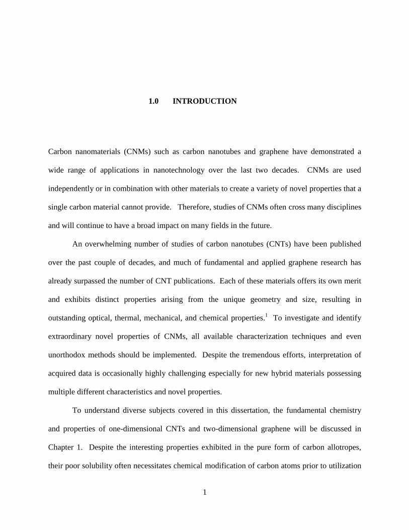
structural materials and reinforced composites.6 CNTs are essentially rolled up graphene sheets
(Figure 1.1), but their unique shapes have imparted them different properties and enabled various
applications.
Figure 1.1 Carbon allotropes based on dimensionality.6
Reprinted with permission from Chem. Rev. 2015, 115 (11), 4744–4822.
Copyright (2015) American Chemical Society.
5
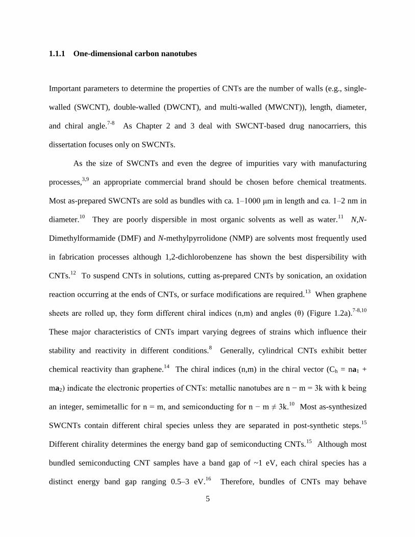
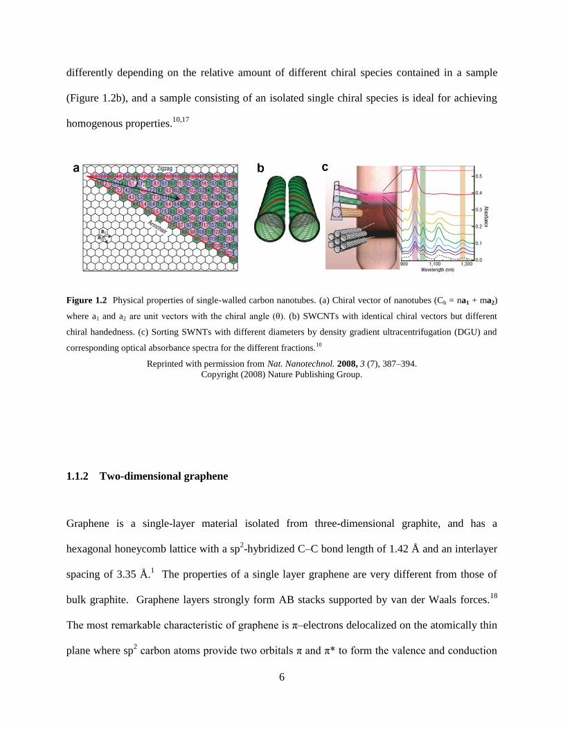
1.1.1 One-dimensional carbon nanotubes
Important parameters to determine the properties of CNTs are the number of walls (e.g., single-
walled (SWCNT), double-walled (DWCNT), and multi-walled (MWCNT)), length, diameter,
and chiral angle.7-8
As Chapter 2 and 3 deal with SWCNT-based drug nanocarriers, this
dissertation focuses only on SWCNTs.
As the size of SWCNTs and even the degree of impurities vary with manufacturing
processes,3,9
an appropriate commercial brand should be chosen before chemical treatments.
Most as-prepared SWCNTs are sold as bundles with ca. 1–1000 μm in length and ca. 1–2 nm in
diameter.10
They are poorly dispersible in most organic solvents as well as water.11
N,N-
Dimethylformamide (DMF) and N-methylpyrrolidone (NMP) are solvents most frequently used
in fabrication processes although 1,2-dichlorobenzene has shown the best dispersibility with
CNTs.12
To suspend CNTs in solutions, cutting as-prepared CNTs by sonication, an oxidation
reaction occurring at the ends of CNTs, or surface modifications are required.13
When graphene
sheets are rolled up, they form different chiral indices (n,m) and angles (θ) (Figure 1.2a).7-8,10
These major characteristics of CNTs impart varying degrees of strains which influence their
stability and reactivity in different conditions.8 Generally, cylindrical CNTs exhibit better
chemical reactivity than graphene.14
The chiral indices (n,m) in the chiral vector (Ch = na1 +
ma2) indicate the electronic properties of CNTs: metallic nanotubes are n − m = 3k with k being
an integer, semimetallic for n = m, and semiconducting for n − m ≠ 3k.10
Most as-synthesized
SWCNTs contain different chiral species unless they are separated in post-synthetic steps.15
Different chirality determines the energy band gap of semiconducting CNTs.15
Although most
bundled semiconducting CNT samples have a band gap of ~1 eV, each chiral species has a
distinct energy band gap ranging 0.5–3 eV.16
Therefore, bundles of CNTs may behave
6
differently depending on the relative amount of different chiral species contained in a sample
(Figure 1.2b), and a sample consisting of an isolated single chiral species is ideal for achieving
homogenous properties.10,17
Figure 1.2 Physical properties of single-walled carbon nanotubes. (a) Chiral vector of nanotubes (Ch = na1 + ma2)
where a1 and a2 are unit vectors with the chiral angle (θ). (b) SWCNTs with identical chiral vectors but different
chiral handedness. (c) Sorting SWNTs with different diameters by density gradient ultracentrifugation (DGU) and
corresponding optical absorbance spectra for the different fractions.10
Reprinted with permission from Nat. Nanotechnol. 2008, 3 (7), 387–394.
Copyright (2008) Nature Publishing Group.
1.1.2 Two-dimensional graphene
Graphene is a single-layer material isolated from three-dimensional graphite, and has a
hexagonal honeycomb lattice with a sp2-hybridized C–C bond length of 1.42 Å and an interlayer
spacing of 3.35 Å.1 The properties of a single layer graphene are very different from those of
bulk graphite. Graphene layers strongly form AB stacks supported by van der Waals forces.18
The most remarkable characteristic of graphene is π–electrons delocalized on the atomically thin
plane where sp2 carbon atoms provide two orbitals π and π* to form the valence and conduction
7
bands.19
The orthogonal π and π* orbitals touching at the hexagonal lattice points (Dirac points)
do not overlap with each other, rendering graphene zero band gap semimetallic.19-20
The
massless electrons with high carrier mobility, which is dramatically different from epitaxially
grown conventional 2D semiconducting layers, have garnered much attention primarily as an
alternative to silicon electronics.20
However, the zero band gap property limits the direct
applications of graphene, especially in standard logic circuits and devices such as transistors due
to high current leakage and energy dissipation.21
In addition to the excellent electron
conductivity and ambipolarity in the field effect configuration, graphene possesses outstanding
mechanical, thermal, and optical properties.21-22
For example, the optical transparency of
graphene is particularly advantageous for conductive electrodes in touch screens and flexible
electronics.22
Few-layer graphene can be isolated by both top-down and bottom-up approaches.
Generally, top-down approaches have been found more efficient, such as liquid-phase exfoliation
of graphite, mechanical exfoliation (e.g., pull-off by cellophane tape and cleavage with a razor),
reduction of graphite oxide (GO), and unzipping of CNTs.23-26
Preparation of free-standing,
atomically thin layered graphene without generating additional defects is crucial. Random
defects generated in the course of mechanical and chemical treatment reduce the homogeneity of
samples, and may degrade device performance.20,27
The exfoliated graphene should be
transferred to a different substrate without creating wrinkles and folds, which can be highly
challenging. Some bottom-up methods can remove the cumbersome step of transfer by directly
growing graphene from organic precursors on a substrate using chemical vapor deposition.28-30
Common substrates are SiC, Si, SiO2, and metal substrates (e.g., Cu, Ni, Au).20,31
The direct
8
growth is convenient in that a separate graphene transfer step is not necessary and single-layer
graphene on a dielectric substrate can be directly incorporated into device fabrication.30
Once single- or few-layer of graphene is isolated, the energy band gap should be tuned
for electronic devices. To open the energy band gap of graphene, precise manipulation of
defects, edges, and strain is required to provide high quality 2D crystal lattice. These graphene-
like materials bearing semiconducting properties include reduced graphene oxide (rGO) prepared
from graphene oxide (GO), holey graphene, and graphene nanoribbons.6,22-23,32
Fabrication
methods for obtaining the controlled nanostructures of these graphene-based materials will be
continuously investigated to develop excellent semiconducting materials.
1.1.3 Characterization methods
Microscopy and spectroscopy are implemented to characterize CNMs and CNM composites.20,33
Transmission electron microscopy (TEM) and scanning electron microscopy (SEM) are imaging
techniques most commonly employed in nanoscience. TEM provides information on size, shape,
and aggregation/dispersion using high-energy electron beam (up to 300 keV) and is especially
useful for identifying structural integrity and changes after surface modification.34
Atomic force
microscopy (AFM) employs a cantilever to measure the force (attraction/repulsion) between the
sample surface and the probe on the order of nanometers. The most powerful feature of AFM is
to resolve the height profile of a sample–substrate. Theoretically the vertical (or depth)
resolution can be achieved up to 0.1 nm, allowing estimation of the thickness of single-layer
graphene.21
9
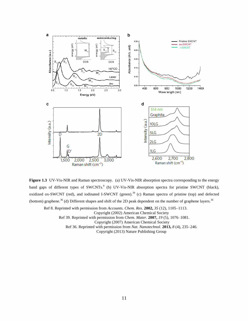
Optical spectroscopy is a noninvasive tool for analyzing structure-dependent optical
transitions of CNMs. Major techniques routinely used in CNM characterization are UV-Vis-
Near Infrared (UV-Vis-NIR), infrared (IR), Raman, and photoluminescence (PL).8,33-34
UV-Vis-
NIR spectroscopy has been frequently used to characterize the distinct electronic transition (i.e.,
energy gap) of metallic and semiconducting carbon nanotubes (Figure 1.3a) corresponding to the
energy density states.15
In addition, the dispersion condition (e.g., bundled vs. separate
nanotubes) and the electronic perturbation caused by the conversion from sp2 to sp
3 hybridization
upon covalent functionalization are translated into the absorption profile (Figure 1.3b).35
Raman spectroscopy has provided insights into the properties of sp2 carbon allotropes
including CNTs and graphite/graphene (Figure 1.3c).36-37
The major peaks characteristic of the
graphitic lattice are shown in Figure 1.3c. G (1584 cm−1
) and G′ (2700 cm−1
) bands are
attributed to the intrinsic pristine sp2 graphitic structure.
21 If a sample consists of pure sp
2
carbon atoms, a sharp G peak is observed.38
The G′ peak is most useful for probing the thickness
of graphite flakes (i.e., the number of layers) based on the peak shape and intensity.38
D (1350
cm−1
) and D′ (1617 cm−1
) bands are associated with the density of defects where symmetry is
broken due to the formation of vacancy and the altered hybridization of carbon bonds.37
The
ratio of ID/IG estimated by measuring the height or the area under the curve can provide a
convenient metric of sp3-defects to pristine sp
2 graphitic carbons, and the bandwidth of D′ band
indicates the degree of vacancy-defect.36-37
The 2D peak (2680 cm−1
) provides information on
the number and the relative orientation of graphene layers by showing significant changes in
shape and intensity (Figure 1.3d).36
FTIR and X-ray photoelectron spectroscopy (XPS) are used to identify organic functional
groups incorporated into the graphitic lattice.34
Bulk samples can be analyzed with FTIR, but
10
some functional groups show weak signals for accurate characterization.33
Thus XPS, which
quantifies the binding energy of photoelectrons ejected from the sample, is utilized to probe
defects and covalently functionalized samples.33
XPS measures the atomic content and identifies
the chemical environment of an atom of interest when samples are irradiated with X-rays, but the
surface sensitivity is limited to the small inelastic mean free path (<10 nm) of the ejected
photoelectrons.34
Although it can be crucial to the analysis of some elemental information and
bond types, the deconvolution data process of XPS spectra can be sometimes ambiguous and
subjective.34
11
Figure 1.3 UV-Vis-NIR and Raman spectroscopy. (a) UV-Vis-NIR absorption spectra corresponding to the energy
band gaps of different types of SWCNTs.8 (b) UV-Vis-NIR absorption spectra for pristine SWCNT (black),
oxidized ox-SWCNT (red), and iodinated I-SWCNT (green).39
(c) Raman spectra of pristine (top) and defected
(bottom) graphene.36
(d) Different shapes and shift of the 2D peak dependent on the number of graphene layers.36
Ref 8. Reprinted with permission from Accounts. Chem. Res. 2002, 35 (12), 1105–1113.
Copyright (2002) American Chemical Society
Ref 39. Reprinted with permission from Chem. Mater. 2007, 19 (5), 1076–1081. Copyright (2007) American Chemical Society
Ref 36. Reprinted with permission from Nat. Nanotechnol. 2013, 8 (4), 235–246.
Copyright (2013) Nature Publishing Group
12
1.2 POLYMER–CARBON NANOMATERIAL COMPOSITES
Polymer–carbon nanomaterial composites refer to systems made of a polymer matrix and CNM
particles, which can be found in a broad range of materials such as biomaterials and surface
catalysts as well as structural reinforcement. Polymers and CNMs are ideal for producing
lightweight materials, and a variety of new composites can be designed with the diverse types of
polymers available on the market.40
To integrate the unique characteristics of each component
into a composite, the surface properties, polarity, and dispersibility in solvents of each
component should be examined to ensure good compatibility and long-term stability.41
To
prepare CNM-based polymer composites, chemical modification (i.e., covalent and noncovalent
functionalization) of CNMs is often required to optimize the compatibility before blending with
polymers.42
Therefore, the types of chemical treatment are discussed first, and then examples of
polymer–CNM composites are selected to introduce the subjects covered in this dissertation.
1.2.1 Covalent and noncovalent chemistry of carbon nanomaterials
Generally, noncovalent functionalization, also often described as physical adsorption onto the
graphitic surface, offers relatively convenient routes to modify the surface properties of CNMs
without undergoing rigorous chemical alteration of the original material.43
On the other hand,
covalent functionalization of conjugated π-systems requires aggressive reaction conditions to
break the inert sp2 C–C bond in the graphitic lattice.
13 Nevertheless, the oxidation process is the
most important covalent functionalization method, which introduces oxygen-containing
functionalities (e.g., carboxylic, hydroxyl, and epoxy groups) into both the edge and the basal
13
plane of CNMs.13,44
These new functional groups impart hydrophilicity to inherently
hydrophobic CNMs and also alter the original solubility.13
Oxidation of CNTs with strong
oxidants (e.g., H2O2/H2SO4 or HNO3/H2SO4) provides a means to shorten the length, and more
oxidized samples tend to have a greater number of defects than pristine CNTs.45
Oxidation of
graphene provides a chemical route for exfoliation as well as newly incorporates oxygen-
containing groups, which facilitates delamination between graphene layers.46
Both oxidized
CNTs and GO can be kinetically suspendable even in water for ca. 100 days due to hydrogen
bonding,47
but aggregates slowly form and precipitate out over an extended period of time. The
extent of dispersibility range can be further controlled by the oxidation method and the degree of
oxidation.48
Thus oxidized CNTs and GO are common precursors for multiple synthetic steps by
covalent functionalization.49
Figure 1.4 shows covalent chemistry schemes utilized in CNTs and
graphene.50-51
Two different methods for functionalization with polymers have been developed: (1)
Grafting-To approaches involve coupling between functional groups (e.g., carboxylic and
hydroxyl groups) on CNMs and the end-group of polymer chains, resulting in the formation of
covalently linked polymer–nanocomposites.41,52
Occasionally, linkers (or spacers) such as amide
and ester derivatives are connected to CNMs, followed by coupling reaction with a polymer.49, 52
(2) Grafting-From approaches require a polymerization initiator reacting on the CNM surface
where in situ polymerization occurs on the activated functional groups of CNMs. Atom transfer
radical polymerization (ATRP), reversible addition-fragmentation chain transfer (RAFT), ring
opening polymerization (ROP), and many other methods were developed.41,52
Grafting-From
methods provide higher grafting density than Grafting-To methods because the polymer growth
is impeded by steric hindrance.41
14
Another type of covalent functionalization is chemical doping which facilitates the
substitution of heteroatoms (e.g., nitrogen and boron) with graphitic carbon atoms without
altering the original sp2 hybridization of carbons.
50 The doping process is based on catalysis and
disproportionation, in which CNMs are subject to an atomic-nitrogen flow and nitrogen atoms
are doped by N2 dissociation in microwave plasma.53
Doping is employed mainly to control the
Fermi level and the properties of CNM-based electronics.20, 53
Noncovalent functionalization is achieved by intermolecular interactions between the
polymer and the CNM, such as π–π stacking, CH–π, van der Waals, electrostatic, and
nonspecific hydrophobic interactions.43
Oxidized CNMs such as ox-SWCNT and GO can have
significant contributions from hydrogen and ionic bonding interactions in addition to π–π
stacking.50
Noncovalent functionalization may form weak interfaces because of the dynamic
nature of noncovalent bonding, and thus the stability of composites can be dependent on the
polymer–solvent interaction in solution.43
However, when cooperative intermolecular bonding
occurs between polymers and CNMs that have a large number of aromatic rings fused together
on the surface, the bond strength can significantly increase, allowing the formation of
sufficiently robust polymer–CNM composites.43
The extended π–conjugation and planarity of
graphene impart stronger π−π interactions with small aromatic molecules (e.g., pyrene,
quinoline, and porphyrin) than rGO and GO.43,54
Even rGO reduced from GO with sp3 defects
exhibits much higher binding affinity with sulfonated aluminum phthalocyanine than GO and
SWCNTs.54-55
Therefore, the planar nanostructure can result in enhanced dispersibility,
biocompatibility, binding capacity, and sensing properties.43
The one-dimensionality of CNTs
does not impart the binding affinity arising from π–π stacking as strong as two-dimensional
graphene.55
However, CNTs have shown effective, strong binding with linear polymers that can
15
wrap around the CNT sidewall and remain undisrupted in solution.13
The binding strength
dependent on hydrophilicity/hydrophobicity can be further tuned by the functional groups of
CNTs and polymers.56
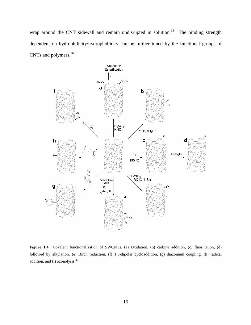
Figure 1.4 Covalent functionalization of SWCNTs. (a) Oxidation, (b) carbine addition, (c) fluorination, (d)
followed by alkylation, (e) Birch reduction, (f) 1,3-dipolar cycloaddition, (g) diazonium coupling, (h) radical
addition, and (i) ozonolysis.49
16
1.2.2 Applications of polymer–carbon nanomaterial composites
Polymer–carbon nanomaterial composites composed of CNTs and graphene have demonstrated
excellent properties particularly in mechanical, electrical, and thermal applications.41,57
Both
CNTs and graphene find numerous applications as composite reinforcers,40,52
conducting
materials for electrical devices,58-59
biomedical devices,60
etc. The production of CNT-based
composites is generally more costly than graphene due to the use of metal catalysts in the CNT
synthesis.20
Nonetheless, needle-like 1D CNT composites would be more effective for particular
applications such as intracellular drug delivery.61
Flat 2D polymer−graphene composites
featuring large surface coverage would make excellent surface catalysts and gas separation
membranes.46
Here we focus on polymer–CNM composites used in three different areas, whose
relevant research topics will be investigated in later chapters.
1.2.2.1 Polymer reinforcement
Polymer reinforcement finds useful applications in structural materials because low density and
high aspect ratios provide extraordinary mechanical properties.40
Reinforced materials are
manufactured for lightweight with CNT loadings of 0.1–20 wt % while increasing the tensile
modulus and strength to bear strong deformations.40
Composites are prepared by blending the
low fraction of CNM-fillers with a polymer matrix44
or by in situ polymerization which provides
better interaction during the growth stage.41
Before blending with a polymer matrix, CNM fillers
are chemically treated to ensure good dispersion.40
Even moderate agglomeration of CNTs
impacts the diameter and length distributions of the filler, decreasing the surface aspect ratio and
stress transfer.40
Further investigations of tunable mechanical properties are undergoing to
optimize the interface between polymers and CNMs.
17
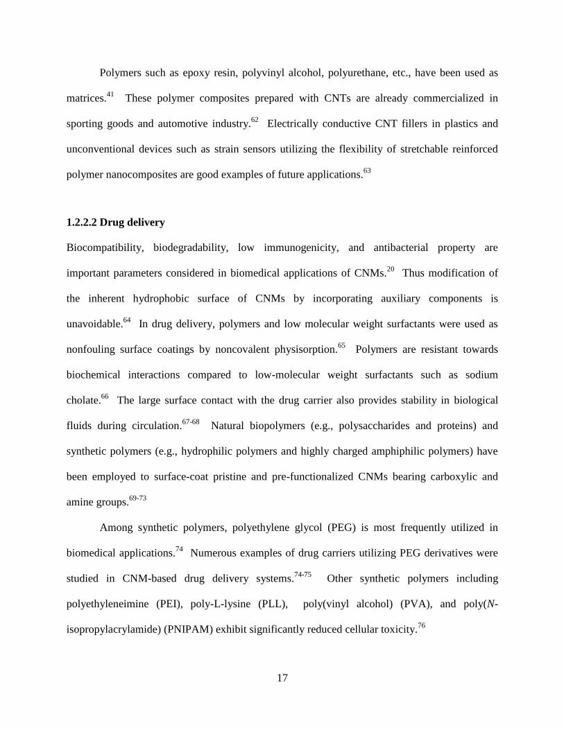
Polymers such as epoxy resin, polyvinyl alcohol, polyurethane, etc., have been used as
matrices.41
These polymer composites prepared with CNTs are already commercialized in
sporting goods and automotive industry.62
Electrically conductive CNT fillers in plastics and
unconventional devices such as strain sensors utilizing the flexibility of stretchable reinforced
polymer nanocomposites are good examples of future applications.63
1.2.2.2 Drug delivery
Biocompatibility, biodegradability, low immunogenicity, and antibacterial property are
important parameters considered in biomedical applications of CNMs.20
Thus modification of
the inherent hydrophobic surface of CNMs by incorporating auxiliary components is
unavoidable.64
In drug delivery, polymers and low molecular weight surfactants were used as
nonfouling surface coatings by noncovalent physisorption.65
Polymers are resistant towards
biochemical interactions compared to low-molecular weight surfactants such as sodium
cholate.66
The large surface contact with the drug carrier also provides stability in biological
fluids during circulation.67-68
Natural biopolymers (e.g., polysaccharides and proteins) and
synthetic polymers (e.g., hydrophilic polymers and highly charged amphiphilic polymers) have
been employed to surface-coat pristine and pre-functionalized CNMs bearing carboxylic and
amine groups.69-73
Among synthetic polymers, polyethylene glycol (PEG) is most frequently utilized in
biomedical applications.74
Numerous examples of drug carriers utilizing PEG derivatives were
studied in CNM-based drug delivery systems.74-75
Other synthetic polymers including
polyethyleneimine (PEI), poly-L-lysine (PLL), poly(vinyl alcohol) (PVA), and poly(N-
isopropylacrylamide) (PNIPAM) exhibit significantly reduced cellular toxicity.76
18
In addition to biocompatibility, polymer topology (e.g., linear, branched, star, and
dendrimer) can be an important parameter to be considered with respect to drug loading and
circulation.77
Linear chains of PEG and PEG derivatives can efficiently wrap around CNTs and
also be grafted on GO.64,78
Two-dimensional polymers could provide more effective surface
coverages with graphene.69
However, most 2D polymers have not been much explored as
nonfouling surface coating in biomedical applications due to poor solubility in water.79
1.2.2.3 Chemical sensing
Polymer–CNM composites have garnered a great deal of interest in the design of electrochemical
sensors and have shown promise for use in flexible devices.20,59,80
The sensor response relies on
charge/electron transfer upon chemical interactions of the analyte and the sensing moiety.81
Large surface areas, high adsorption sites in thin composite films, and the excellent surface
contact between conjugated polymers and graphene allow for high sensitivity in the detection of
analytes and enhanced current signals in conductance compared to bulk materials.82
Especially,
many 2DPs are composed of aromatic ring-based conjugated macromolecules that impart
planarity and rigidity, and thus the 2DP–graphene composite can be an excellent heterostructure
self-assembled by cooperative π–π stacking.80
The high surface-to-volume ratio and the charge
mobility of graphene (or reduced graphene oxide) provide an excellent semiconducting channel
for field-effect transistor (FET) sensors.83
Despite the successful synthesis of 2DP–graphene
composites, their applications to electronic devices have been rarely studied.84
Various polymers have been utilized in electronic sensing devices.46
Both intrinsically
conducting (e.g., polyacetylene, polythiophene, and polyaniline)85
and nonconducting polymers
(e.g., polystyrene, poly(vinylalcohol), poly(methyl methacrylate), and polyurethane)86
were
employed to achieve particular goals and synergistic effects. As good conductivity can be
19
achieved with low CNM loading (<10 wt %),57
the use of conducting polymers is not critical.
However, to be applicable in electronic sensing devices, polymer–CNM composites should be
semiconducting. CNTs were found to provide sufficient sensitivity for detecting gas analytes
(NO2 and NH3) without employing a sensing material,87
but polyethyleneimine-coated SWCNTs
showed enhanced selectivity and sensitivity to the same analytes.88
To achieve high selectivity
in analyte detection, the sensing moiety, which is designed primarily based on molecular
recognition of the analyte, can be incorporated into devices by chemically modifying either
polymers or CNMs.89
20
1.3 OXIDATION OF CARBON NANOMATERIALS
The oxidative reaction pathways of CNMs have been studied in the context of biological and
nonbiological settings, in which oxidation results in simple chemical transformation to
aggressive defect generation.45,90-91
Oxidation in biological settings involves endogenous species
such as enzymes and reactive oxidation species (ROS) in situ generated in many complex
metabolic pathways.92
The biological oxidation of CNMs began to be studied only a few years
ago in relation to nanotoxicology mainly focusing on environmental health and safety.93
The
oxidative metabolism investigated in earlier studies was inflammatory responses by the innate
immune system.94
Despite the recent efforts to elucidate the toxicity of CNMs, only a few
studies have investigated polymer–CNM composites in the context of oxidation.95
Thus more
studies for predicting the long-term safety of chemically diverse CNMs should be pursued in the
future, as these issues will have a direct impact on their palpable applications to biomedical
technology.93
Oxidation of CNMs in nonbiological settings is not restricted to any particular conditions.
Previous studies introduced the degradation of GO using well-established oxidation methods
such as Fenton chemistry.91,96
Surface modification, especially oxidation of CNMs has been
indispensable as a prefabrication treatment method,13,50
and thus exploration of new oxidation
routes will provide convenient means for flexible fabrication and manufacturing processes. The
easiest way to come up with a new nonbiological method would be mimicking biosystems.97-98
Here, iron-catalyzed oxidation pathways in nonbiological systems will be briefly discussed as
ferric and ferrous ions are involved in many catalytic oxidation systems as well as Fenton
chemistry.
21
1.3.1 Oxidation in biological systems
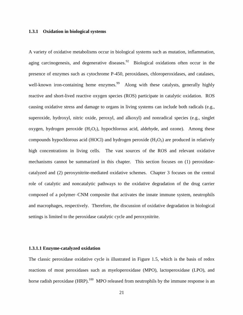
A variety of oxidative metabolisms occur in biological systems such as mutation, inflammation,
aging carcinogenesis, and degenerative diseases.92
Biological oxidations often occur in the
presence of enzymes such as cytochrome P-450, peroxidases, chloroperoxidases, and catalases,
well-known iron-containing heme enzymes.99
Along with these catalysts, generally highly
reactive and short-lived reactive oxygen species (ROS) participate in catalytic oxidation. ROS
causing oxidative stress and damage to organs in living systems can include both radicals (e.g.,
superoxide, hydroxyl, nitric oxide, peroxyl, and alkoxyl) and nonradical species (e.g., singlet
oxygen, hydrogen peroxide (H2O2), hypochlorous acid, aldehyde, and ozone). Among these
compounds hypochlorous acid (HOCl) and hydrogen peroxide (H2O2) are produced in relatively
high concentrations in living cells. The vast sources of the ROS and relevant oxidative
mechanisms cannot be summarized in this chapter. This section focuses on (1) peroxidase-
catalyzed and (2) peroxynitrite-mediated oxidative schemes. Chapter 3 focuses on the central
role of catalytic and noncatalytic pathways to the oxidative degradation of the drug carrier
composed of a polymer–CNM composite that activates the innate immune system, neutrophils
and macrophages, respectively. Therefore, the discussion of oxidative degradation in biological
settings is limited to the peroxidase catalytic cycle and peroxynitrite.
1.3.1.1 Enzyme-catalyzed oxidation
The classic peroxidase oxidative cycle is illustrated in Figure 1.5, which is the basis of redox
reactions of most peroxidases such as myeloperoxidase (MPO), lactoperoxidase (LPO), and
horse radish peroxidase (HRP).100
MPO released from neutrophils by the immune response is an
22
enzyme containing two heme iron centers.101
Respiratory burst comprising NADPH oxidase and
O2 produces H2O2, one of a reactive oxygen species (ROS).101
The H2O2 concentration in
stimulated neutrophils and monocytes is about 1.5 nmol/104 cells per hour.
102 Once H2O2 is
generated, MPO (native enzyme, FeIII
) is converted into MPO-I (FeIV
=O+•
) in a two-electron
process, yielding hydroxyl radical (•OH) and a subsequent conversion into MPO-II (FeIV
=O)
proceeds in a one-electron reducing process.100
The original state of MPO is restored through
another one electron reduction in which a reducing substrate (RH) reacts with MPO-II an order
of magnitude slower than with MPO-I.100
Important by-products generated from the oxidation
cycle are reactive radical species hydroxyl radical (•OH) and alkyl radical (R•).103
A major difference between MPO and HRP is the generation of a strong oxidant HOCl in
the MPO-catalyzed oxidative cycle. Once MPO-I is formed in Step I, it oxidizes chloride (Cl−),
abundant in physiological fluids (about 0.14 mM), and produces a strong oxidant HOCl.100
Hypochlorous acid in equilibrium with hypochlorite (−OCl/HOCl) at physiological conditions is
one of the most important antimicrobial agent that can effectively kill bacteria, germs, and any
harmful species.100
23
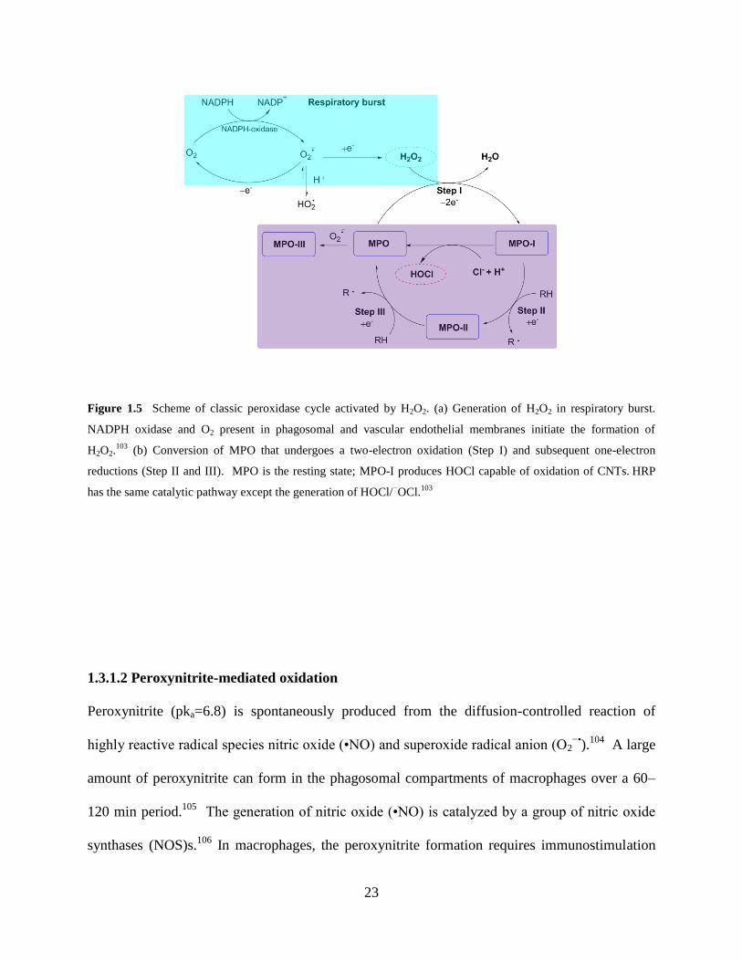
Figure 1.5 Scheme of classic peroxidase cycle activated by H2O2. (a) Generation of H2O2 in respiratory burst.
NADPH oxidase and O2 present in phagosomal and vascular endothelial membranes initiate the formation of
H2O2.103
(b) Conversion of MPO that undergoes a two-electron oxidation (Step I) and subsequent one-electron
reductions (Step II and III). MPO is the resting state; MPO-I produces HOCl capable of oxidation of CNTs. HRP
has the same catalytic pathway except the generation of HOCl/−OCl.
103
1.3.1.2 Peroxynitrite-mediated oxidation
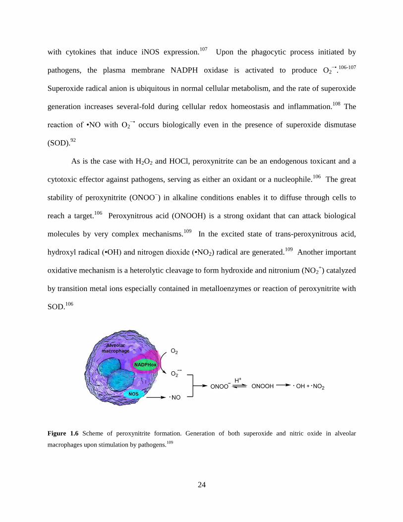
Peroxynitrite (pka=6.8) is spontaneously produced from the diffusion-controlled reaction of
highly reactive radical species nitric oxide (•NO) and superoxide radical anion (O2−•
).104
A large
amount of peroxynitrite can form in the phagosomal compartments of macrophages over a 60–
120 min period.105
The generation of nitric oxide (•NO) is catalyzed by a group of nitric oxide
synthases (NOS)s.106
In macrophages, the peroxynitrite formation requires immunostimulation
24
with cytokines that induce iNOS expression.107
Upon the phagocytic process initiated by
pathogens, the plasma membrane NADPH oxidase is activated to produce O2−•
.106-107
Superoxide radical anion is ubiquitous in normal cellular metabolism, and the rate of superoxide
generation increases several-fold during cellular redox homeostasis and inflammation.108
The
reaction of •NO with O2−•
occurs biologically even in the presence of superoxide dismutase
(SOD).92
As is the case with H2O2 and HOCl, peroxynitrite can be an endogenous toxicant and a
cytotoxic effector against pathogens, serving as either an oxidant or a nucleophile.106
The great
stability of peroxynitrite (ONOO−) in alkaline conditions enables it to diffuse through cells to
reach a target.106
Peroxynitrous acid (ONOOH) is a strong oxidant that can attack biological
molecules by very complex mechanisms.109
In the excited state of trans-peroxynitrous acid,
hydroxyl radical (•OH) and nitrogen dioxide (•NO2) radical are generated.109
Another important
oxidative mechanism is a heterolytic cleavage to form hydroxide and nitronium (NO2+) catalyzed
by transition metal ions especially contained in metalloenzymes or reaction of peroxynitrite with
SOD.106
Figure 1.6 Scheme of peroxynitrite formation. Generation of both superoxide and nitric oxide in alveolar
macrophages upon stimulation by pathogens.109
25
1.3.1.3 Oxidative biodegradation of carbon nanomaterials
Currently, two different oxidative pathways have been investigated concerning the CNT
degradation: (1) enzyme (MPO, LPO, and HRP)-catalyzed and (2) peroxynitrite-mediated
oxidations.107,110-113
Since our research group demonstrated the horseradish peroxidase (HRP)-
catalyzed degradation of CNTs in the seminal work,113
the degradation of SWCNTs,114
MWNTs,115
and GO116-117
have been investigated further. In addition, the role of peroxidases
and their varying degrees of oxidation of pristine and functionalized CNMs were investigated
with myeloperoxidase (MPO)110,118
and eosinophil peroxidase.111
The CNM biodegradation was
also corroborated by evidence of the mitigating effect of an antioxidant glutathione in the MPO
oxidative system.118
Our research group and others conjectured that hypochlorite/hypochlorous acid and the
reactive intermediates formed in the course of MPO cycle were capable of degrading carbon
nanotubes.110,116,119
MPO-catalyzed degradation occurs both intra- and extra-cellularly
(neutrophil extracellular trap).95
Three major steps are involved in the CNT degradation by the
MPO catalytic cycle: (1) formation of a HOCl (Step I), (2) oxidation of Ar–H (Step II and III),
and (3) the resulting formation of free radical species.118
EPO oxidation has the same catalytic
cycle except for the formation of hypobromous acid (HOBr) instead of HOCl.111
The role of
reactive free radical species has not been fully explained. It is highly likely that aromatic as well
as hydroxyl radicals generated during the peroxidase cycle may induce a variety of radical
transformations with sp2 carbon atoms. Either H2O2 or HOCl alone can be a strong oxidant, and
thus oxidation of CNTs was investigated ex vivo. However, these oxidants alone did not degrade
SWCNTs as effectively as the MPO system. Although it seems reasonable that the coexistence
of H2O2 and HOCl can create a very powerful oxidation condition, the mechanistic details of
26
how the reactive radical species and HOCl formed in the MPO cycle have not been elucidated.
When the oxidative cleavage of sp2 C–C bonds proceeds extensively in the basal plane, vacancy
defects are formed, generating large holes and by-products (e.g., CO, CO2, and oxidized
carbonaceous products).90
Graphene oxide (GO) treated with HRP and H2O2 was degraded
whereas reduced graphene oxide (rGO) was intact under the same oxidative condition.117
Computational docking studies showed that HRP was preferentially bound to the basal plane
rather than the edge. When GO was treated with MPO, aggregated GO failed to degrade.117
However, highly dispersed samples were completely metabolized.116
Noncovalently functionalized CNTs coated with pulmonary phospholipid surfactants
(e.g., phosphatidyl choline and phosphatidyl serine)120
and polyethylene glycols (PEG)95, 121
were
also investigated. Anionic phosphatidyl serine showed a 1.8 times higher uptake of ox-SWCNT
by neutrophils than phosphatidyl choline.120
PEGylated ox-SWCNTs were exposed to activated
neutrophils ex vivo and in vitro.95,121
Both covalent and noncovalent functionalization methods
were employed for MPO-catalyzed degradation.95
The in vitro study revealed that covalently
functionalized samples degraded faster, and that the low molecular weight PEG (e.g., 2 kDa vs.
10 kDa) was more efficient in the oxidative degradation.95
The small PEG features low grafting
density, allowing for better exposure of SWCNTs to MPO and facile degradation without the
MPO–PEG interaction.95
Despite the faster degradation rates observed in the ex vivo study, the
molecular weight and the type of functionalization of PEG did not influence the degradation
kinetics as much as they appeared in the in vitro study.95
In addition, this study also suggests
that other enzymes released from neutrophils ex vivo, such as neutrophil elastase and
antibacterial serine proteases, could participate in PEG stripping besides MPO. Therefore,
27
different ex vivo experimental methods, i.e., the addition of isolated MPO vs. activated
neutrophils, can impact the degradation kinetics.95
Under the same oxidative condition, the degree of nanotube degradation was found to be
dependent upon the different functional groups of the nanotube.90
It was also reported that
oxidized nanotubes (ox-CNTs) were more susceptible to oxidative biodegradation than pristine
samples (nonfunctionalized nanotubes).90,110,115,122
Because functionalization introduces new
defect sites on the sidewalls, such as chemically reactive bonds and heteroatoms on the graphitic
lattice, a large number of covalently functionalized CNTs become susceptible to oxidation.123
The peroxidase-catalyzed systems indicated that the type of surface functionalization was critical
in influencing the fate of degradation, and that the strong electrostatic interaction between
positively charged residues of MPO and an anionic species (e.g., carboxylate of ox-SWCNT)
promoted the enzymatic degradation based on a docking study.110
The peroxynitrite-mediated degradation of ox-SWCNTs in vitro was investigated in
activated macrophages known to produce peroxynitrite.107
Although NADPH oxidase and iNOS
synthases are involved in the peroxynitrite generation,104,106
these enzymes do not directly
interact with CNTs, different from the specific binding interaction between CNTs and the
reactive intermediates of peroxidases (MPO and EPO).107
Thus peroxynitrite-mediated oxidation
appears less dependent on the surface charge of initial CNTs (i.e., the number of carboxylate
groups).107
28
1.3.2 Catalytic oxidation of nonbiological systems
One of the important strategies for nonbiological catalytic oxidation is to mimic biological
processes and implement green chemistry.124
For example, redox enzymes for catalytic
oxidation in biological systems are often translated into synthetic models consisting of transition
metals as catalysts and clean oxidants such as O2 and H2O2.124
Catalytic oxidation that can
proceed at room temperature and ambient pressure instead of high temperatures are ideal for the
environment and economy. However, only a few nonbiological catalytic oxidations have been
studied with respect to CNMs.91,96,125-126
They are employed mainly to modify the original zero
energy band gap of graphene, rather than aiming at degrading CNMs.126
Fenton-like reactions
based on the original Fenton chemistry have been known to be very efficient in the formation of
oxidative defects,91
but further applications have not been actively pursued. Slight changes in
reaction condition using UV light-promoted or Cu(I)/Cu(II)127
instead of Fe(II)/Fe(III) have been
most frequently employed. In Chapter 4, the Fenton-like reactions using a Cu(II) coordinated
supramolecular polymer catalyst will be discussed. In the same vein, metalloporphyrin
complexes have been widely used as catalysts in various organic reactions with oxidants (e.g.,
PhIO, NaOCl, KHSO5, and H2O2).98
However, the use of a synthetic metalloporphyrin complex
in the fabrication of CNMs has not been reported other than in the case of the patterned graphite
described in Chapter 5 of this dissertation.
1.3.2.1 Fenton-like oxidation
The Fenton-like mechanism is based on an electron transfer between hydrogen peroxide and a
metal catalyst (e.g., Fe2+
, Cu+).
128 The classic Fenton reaction is catalyzed by ferrous ions (Fe
2+)
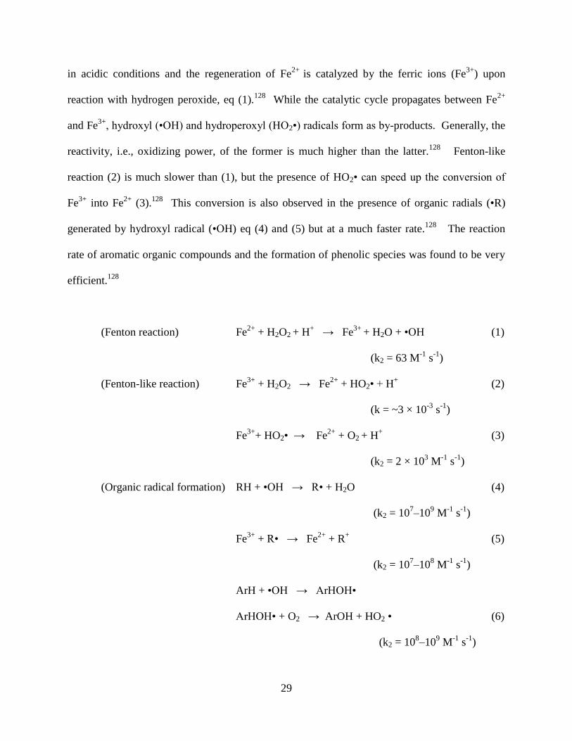
29
in acidic conditions and the regeneration of Fe2+
is catalyzed by the ferric ions (Fe3+
) upon
reaction with hydrogen peroxide, eq (1).128
While the catalytic cycle propagates between Fe2+
and Fe3+
, hydroxyl (•OH) and hydroperoxyl (HO2•) radicals form as by-products. Generally, the
reactivity, i.e., oxidizing power, of the former is much higher than the latter.128
Fenton-like
reaction (2) is much slower than (1), but the presence of HO2• can speed up the conversion of
Fe3+
into Fe2+
(3).128
This conversion is also observed in the presence of organic radials (•R)
generated by hydroxyl radical (•OH) eq (4) and (5) but at a much faster rate.128
The reaction
rate of aromatic organic compounds and the formation of phenolic species was found to be very
efficient.128
(Fenton reaction) Fe2+
+ H2O2 + H+ → Fe
3+ + H2O + •OH (1)
(k2 = 63 M-1
s-1
)
(Fenton-like reaction) Fe3+
+ H2O2 → Fe2+
+ HO2• + H+ (2)
(k = ~3 × 10⁻³
s-1
)
Fe3+
+ HO2• → Fe2+
+ O2 + H+
(3)
(k2 = 2 × 10³ M
-1 s
-1)
(Organic radical formation) RH + •OH → R• + H2O (4)
(k2 = 107–10
9 M
-1 s
-1)
Fe3+
+ R• → Fe2+
+ R+
(5)
(k2 = 107–10
8 M
-1 s
-1)
ArH + •OH → ArHOH•
ArHOH• + O2 → ArOH + HO2 • (6)
(k2 = 108–10
9 M
-1 s
-1)
30
To enhance the catalytic activity in different environments, this basic oxidative model has
been modified into various conditions and is referred to as Fenton-like reactions. In addition to
Fe(II), copper(II)127
and cobalt(II) can be used as catalysts in the decompositions of polycylic
aromatic hydrocarbons and small aromatic compounds such as benzene, toluene, ethylbenzene,
and xylenes.129
Fenton chemistry is effective under acidic conditions (pH 2–4) whereas cobalt
and copper catalysts can be useful in the wide range of pH 3–9. 129
In addition, different organic
ligands influence the catalytic activity by forming a metal–ligand–radical complex in the
presence of H2O2, which may prevent the aggregation of metal ions in solution and accelerate the
interaction with H2O2.129
1.3.2.2 Synthetic iron porphyrin catalysts
Porphyrin derivatives are probably the most versatile ligands, capable of forming well-defined
complexes with various transition metal ions, notably iron(III), Mn(III), Co(II), and Ru(II).130
The tetrapyrrole ligand structure of porphyrin allows for modification with substituents that can
be linked to pyrrolic β sites or the methines.97
Compared to heme-containing enzymes, synthetic
metalloporphyrin catalysts can be more robust when exposed to a large amount of oxidants.131
Many early examples of metalloporphyrin catalysts were reported in the epoxidation of alkenes
and hydroxylation of alkanes.131
Although electron-rich aromatic substrates have not been
employed for iron porphyrin-catalyzed oxidation, oxidative degradation of lignin and organic
pollutants have also been reported.132
Lignin dimers composed of benzylic and phenyl carbons
were subjected to oxidative cleavage which was sensitive to porphyrin substituents and oxidants
(oxygen donors).133
When immobilized on graphene supports, hemin and iron porphyrin
31
derivatives with H2O2 showed high catalytic activity in the oxidation of a small aromatic
molecule pyrogallol.134
1.3.2.3 Nonbiological catalytic oxidation of carbon nanomaterials
Photo-Fenton reactions have been used in the oxidative degradation of MWCNTs135
and GO.96
The mechanism of the photo-Fenton reaction of GO was elucidated by mass spectrometer
analysis and density functional theory (DFT) calculations.96
The oxidation mechanism of GO
seems similar to that of CNTs in that the oxidant H2O2 is dissociated by UV irradiation into •OH,
a very powerful oxidant, and generates hydroxide, quinone, and carboxylic groups.136
Ultimately, the functional groups with low oxidation states will be converted to higher oxidation
states such as carboxylic acid, followed by decarboxylation and return to the C–H bond
formation. Zhang and coworkers prepared graphene quantum dots (GQDs) with an average size
of 40 nm (width) × 1.2 nm (thickness) using a photo-Fenton oxidation of GO sheets (about
1μm).91
They found that the photo-Fenton reaction of GO was initiated at carbon atoms
connected with oxygen containing groups, and that GQDs were functionalized with carboxylic
groups along the edges.91
The use of metal nanoparticles (NPs) as catalysts is another type of catalytic thermal
oxidation, in which metal NPs are deposited on graphene sheets and annealed at elevated
temperatures. Bulk preparation of holey graphene was demonstrated with an AgNP catalyst on
graphene that was exposed to controlled air oxidation at 250–400 °C, and the high annealing
temperature yielded a high oxygen content in the graphene sample.125
Similarly, AuNPs were
deposited on rGO and catalyzed the oxidation of rGO by •OH as well as the generation of •OH
by UV photolysis.126
The catalytic role of AuNP was attributed to changes in localized oxidation
potentials at the AuNP surface effectively assisting the reaction of •OH with rGO.126
32
2.0 SYNTHESIS OF POLYMER–CARBON NANOTUBE COMPOSITES FOR DRUG
DELIVERY
2.1 CHAPTER PREFACE
This research was conducted in collaboration with the Professor Valerian Kagan group,
Departments of Environmental and Occupational Health, and the Professor Peter Wipf group,
Department of Chemistry at the University of Pittsburgh. These groups provided mitochondria
targeting drugs, TPP-IOA and XJB-5-131, respectively. W. Seo synthesized and characterized
the drug nanoconjugates; Michael W. Epperly administered in vivo experiments; Alexandr A.
Kapralov, Vladmir A. Tyurin, and Yulia Y. Tyurina performed in vitro experiments and
analyzed biological data; E. Skoda synthesized XJB-5-131. W. Seo thanks Seth C. Burkert for
performing X-ray photoelectron spectroscopy (XPS). As biological studies were conducted in
other groups, only the key results of drug conjugates are highlighted in this dissertation.
33
2.2 INTRODUCTION
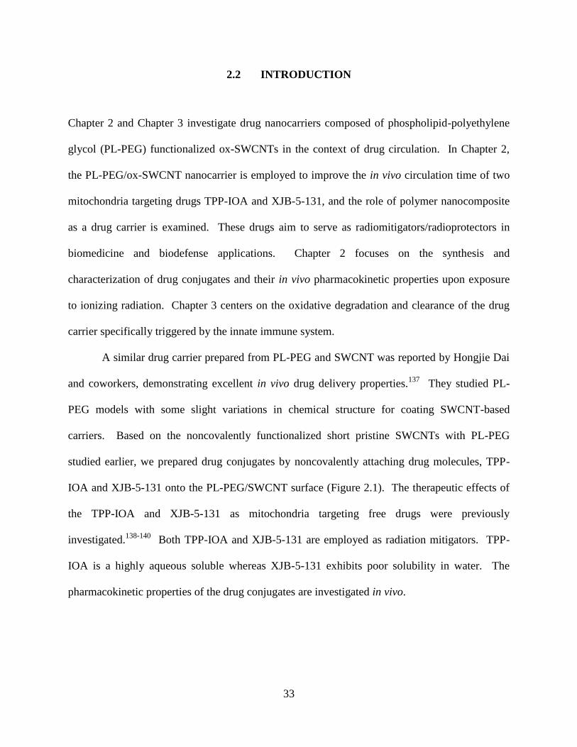
Chapter 2 and Chapter 3 investigate drug nanocarriers composed of phospholipid-polyethylene
glycol (PL-PEG) functionalized ox-SWCNTs in the context of drug circulation. In Chapter 2,
the PL-PEG/ox-SWCNT nanocarrier is employed to improve the in vivo circulation time of two
mitochondria targeting drugs TPP-IOA and XJB-5-131, and the role of polymer nanocomposite
as a drug carrier is examined. These drugs aim to serve as radiomitigators/radioprotectors in
biomedicine and biodefense applications. Chapter 2 focuses on the synthesis and
characterization of drug conjugates and their in vivo pharmacokinetic properties upon exposure
to ionizing radiation. Chapter 3 centers on the oxidative degradation and clearance of the drug
carrier specifically triggered by the innate immune system.
A similar drug carrier prepared from PL-PEG and SWCNT was reported by Hongjie Dai
and coworkers, demonstrating excellent in vivo drug delivery properties.137
They studied PL-
PEG models with some slight variations in chemical structure for coating SWCNT-based
carriers. Based on the noncovalently functionalized short pristine SWCNTs with PL-PEG
studied earlier, we prepared drug conjugates by noncovalently attaching drug molecules, TPP-
IOA and XJB-5-131 onto the PL-PEG/SWCNT surface (Figure 2.1). The therapeutic effects of
the TPP-IOA and XJB-5-131 as mitochondria targeting free drugs were previously
investigated.138-140
Both TPP-IOA and XJB-5-131 are employed as radiation mitigators. TPP-
IOA is a highly aqueous soluble whereas XJB-5-131 exhibits poor solubility in water. The
pharmacokinetic properties of the drug conjugates are investigated in vivo.
34
Figure 2.1 Representation of a nanocarrier and drugs. (a) ox-SWCNT and PL-PEG. (b) TPP-IOA, and (c) XJB-5-
131.
35
2.2.1 Drug nanocarriers and carbon nanotubes
Many different types of drug delivery systems, including the first generation nontargeted and
targeted (or smart) delivery, have been developed to improve the therapeutic effects of
conventional drug administrations.141 Generally, drug carriers are employed to improve
pharmacological properties of existing drugs (e.g., solubility and circulation), and are designed
primarily to protect drug molecules from the external environment.142
Some carriers are built
upon sophisticated molecular systems made of multiple components and functions, resulting in
localized release of therapeutic agents near target cells and tissues with minimal side effects.143-
144
CNT-based molecular vehicles have been utilized in drug and gene delivery, imaging,
and photothermal therapy.74,94
Many examples of these devices have also been developed into a
carrier capable of multiple functionalities such as theranostics, a combination of therapeutic and
imaging contrast agents. The shape of drug carriers plays a role in permeation of the drug
carrier.145
Compared to spherical nanoparticles such as liposomes and micelles, CNTs featuring
1D needle shapes and high aspect ratios (>200:1 of length to width for HiPco SWCNT) are
reportedly advantageous for intracellular drug delivery by endocytosis, allowing facile
translocation of drug carriers into the cytoplasm through cell membranes.146-147
HiPco SWCNTs prepared by high-pressure carbon monoxide disproportionation148
are
employed in drug delivery due to their small diameters (0.8–1.2 nm). For biological
applications, most commercial HiPco CNTs are cut short by chemical and mechanical treatments
(<300 nm in length).149
It is widely accepted that short CNTs are relatively safe whereas pristine
CNTs as long as 10 μm have been shown to cause pulmonary inflammation and mesothelioma in
mice.150
Semiconducting nanotubes have intrinsic fluorescence in the NIR region (λemission =
36
1100–1400 nm, λexcitation = 750–900 nm), which eliminates the need for using toxic fluorophores
in biological studies.151
CNTs are capable of passive self-accumulation near the tumor site
without the aid of the ligand–receptor interaction programmed in targeted drug delivery.145, 152
This phenomenon, referred to as the enhanced permeation and retention (EPR) effect, can also be
observed in other nanoparticle-based drug carriers that are easily trapped onto the irregular,
abnormal surface of cancer cells and tissues.153
Examples of SWCNT-based drug conjugates functionalized by different auxiliary
components are illustrated in Figure 2.2.69
Incorporation of surfactants or hydrophilic polymers
to impart biocompatibility is a common procedure.74
Occasionally, functional modules such as
fluorescence tags for cellular imaging and ligand–target recognition (e.g., antigen–antibody) are
also incorporated into CNT carriers.60,69
Drug molecules can be attached to CNTs covalently as
prodrugs or can be noncovalently bound to the CNT surface through intermolecular interactions
(Figure 4a–c).154
Generally, covalently linked drug molecules can be resistant to random
adsorption by various biomolecules in serum unless the linker is cleaved by metabolic processes.
However, covalent attachment of drug molecules may result in low drug payloads because CNTs
have insufficient anchoring sites for drug conjugation, localized only at the ends and some
defects on the sidewall.151,155-156
To increase the loading capacity, drug molecules are linked to
PEG instead of CNTs.
Drug molecules can also be noncovalently loaded onto SWCNTs.154
Hydrophobic drugs
bearing aromatic moieties such as Doxorubicin are good substrates because the sidewall of
SWCNTs drives π–π stacking.154,157
In addition, the carboxylate of ox–SWCNTs form
electrostatic interactions with positively charged groups (e.g., RNH3+) under physiological
conditions.157
Despite the functionalization of CNTs with hydrophilic or amphiphilic coatings,
37
the inherent poor aqueous solubility of drugs significantly influences the stability and the
pharmacokinetics of drug conjugates as observed in the in vivo pharmacokinetics study of
paclitaxel.155
It was suggested that the high hydrophobicity of paclitaxel would compromise the
biological inertness of a PEG-functionalized SWCNTs, significantly reducing blood circulation
times.155
Figure 2.2 SWCNT-based drug conjugates.69
Reprinted with permission from Chem. Commun. 2012, 48 (33), 3911–3926.
Copyright (2002) Royal Society of Chemistry
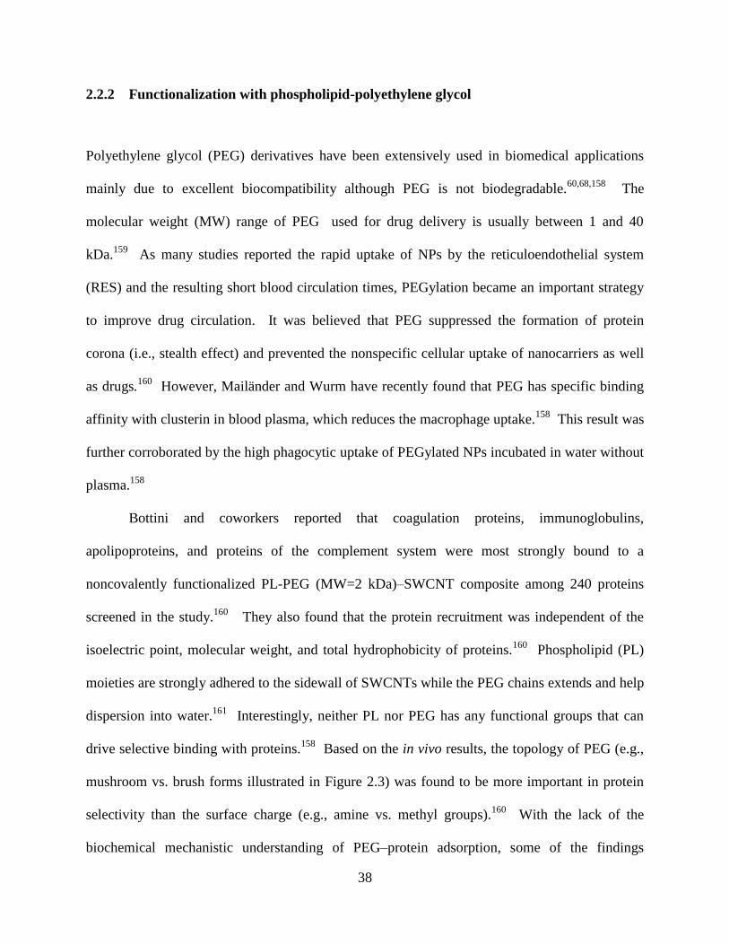
38
2.2.2 Functionalization with phospholipid-polyethylene glycol
Polyethylene glycol (PEG) derivatives have been extensively used in biomedical applications
mainly due to excellent biocompatibility although PEG is not biodegradable.60,68,158
The
molecular weight (MW) range of PEG used for drug delivery is usually between 1 and 40
kDa.159
As many studies reported the rapid uptake of NPs by the reticuloendothelial system
(RES) and the resulting short blood circulation times, PEGylation became an important strategy
to improve drug circulation. It was believed that PEG suppressed the formation of protein
corona (i.e., stealth effect) and prevented the nonspecific cellular uptake of nanocarriers as well
as drugs.160
However, Mailänder and Wurm have recently found that PEG has specific binding
affinity with clusterin in blood plasma, which reduces the macrophage uptake.158
This result was
further corroborated by the high phagocytic uptake of PEGylated NPs incubated in water without
plasma.158
Bottini and coworkers reported that coagulation proteins, immunoglobulins,
apolipoproteins, and proteins of the complement system were most strongly bound to a
noncovalently functionalized PL-PEG (MW=2 kDa)–SWCNT composite among 240 proteins
screened in the study.160
They also found that the protein recruitment was independent of the
isoelectric point, molecular weight, and total hydrophobicity of proteins.160
Phospholipid (PL)
moieties are strongly adhered to the sidewall of SWCNTs while the PEG chains extends and help
dispersion into water.161
Interestingly, neither PL nor PEG has any functional groups that can
drive selective binding with proteins.158
Based on the in vivo results, the topology of PEG (e.g.,
mushroom vs. brush forms illustrated in Figure 2.3) was found to be more important in protein
selectivity than the surface charge (e.g., amine vs. methyl groups).160
With the lack of the
biochemical mechanistic understanding of PEG–protein adsorption, some of the findings
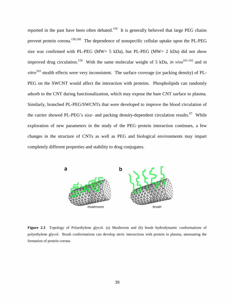
39
reported in the past have been often debated.159
It is generally believed that large PEG chains
prevent protein corona.158,160
The dependence of nonspecific cellular uptake upon the PL-PEG
size was confirmed with PL-PEG (MW= 5 kDa), but PL-PEG (MW= 2 kDa) did not show
improved drug circulation.159
With the same molecular weight of 5 kDa, in vivo161-162
and in
vitro163
stealth effects were very inconsistent. The surface coverage (or packing density) of PL-
PEG on the SWCNT would affect the interaction with proteins. Phospholipids can randomly
adsorb to the CNT during functionalization, which may expose the bare CNT surface to plasma.
Similarly, branched PL-PEG/SWCNTs that were developed to improve the blood circulation of
the carrier showed PL-PEG’s size- and packing density-dependent circulation results.67
While
exploration of new parameters in the study of the PEG–protein interaction continues, a few
changes in the structure of CNTs as well as PEG and biological environments may impart
completely different properties and stability to drug conjugates.
Figure 2.3 Topology of Polyethylene glycol. (a) Mushroom and (b) brush hydrodynamic conformations of
polyethylene glycol. Brush conformations can develop steric interactions with protein in plasma, attenuating the
formation of protein corona.
40
2.2.3 Mitochondria targeting drugs
Protective medical countermeasures need to be developed to prevent ionizing radiation injury
potentially caused by accidental exposure during radiation therapy and terrorism.140
Ionizing
radiation triggers generation of reactive oxygen species (ROS) and radicals arising from
radiolysis of water, inducing mitochondria-mediated cell apoptosis.164
To date, no effective
medical radiation countermeasures against acute and delayed radiation injuries are currently
available.165
Based on the new finding that cytochrome c in mitochondria oxidizes cardiolipin as
the result of radiation-induced apoptosis, 3-hydroxypropyl-triphenylphosphonium-conjugated
imidazole-substituted oleic acid (TPP-IOA) was developed.140
The lipophilic
triphenylphosphonium moiety promotes the drug molecules to efficiently traverse the highly
negative mitochondrial lipid membrane, serving as an excellent selective targeting agent to treat
ROS-induced mitochondrial damage.166
TPP-IOA demonstrated the suppression of cell death
induced by irradiation and protected C57BL6 mice against total body irradiation.140
XJB-5-131 possesses a nitroxide group functionalized into the S segment of a natural
product gramicidin, a peptide-mimetic mitochondrial targeting radiomitigators.167
XJB-5-131
delivers 4-amino-TEMPO, a stable nitroxide radical-based antioxidant scavenging electrons and
ROS.168
The sterically hindered free radical can serve as either an electron-accepting or
electron-donating group, depending on the redox potential of the environment.169
This drug was
found effective in preventing superoxide production in cells and cardoilipin (CL) oxidation in
mitochondria and also in protecting cells against a range of pro-apoptotic triggers such as
actinomycin D and radiation.167
41
2.3 EXPERIMENTAL
2.3.1 Synthesis of drug carrier (PL-PEG/ox-SWCNT)
Raw HiPco (NanoIntegris®) SWCNTs (25 mg) were oxidized in 50 mL of an acid mixture
(H2SO4 /HNO3, 3/1, v/v) in an ultrasonic bath set at 25 ˚C over 3 h 20 min. After thorough
washing with distilled water several times, the ox-SWCNTs were dried under vacuum over 24 h,
which yielded 18 mg. A phospholipid–polyethylene glycol (PL-PEG) was prepared by amide
coupling of DSPE-050PA (115 mg) and TMS(PEG)12 (71 mg) in anhydrous CH2Cl2 (3.0 mL).
After 12 h, N,N-dicyclohexylcarbodiimide (DCC) (20 mg, 97 mmol) and 4-
dimethylaminopyridine (DMAP) (10 mg, 82 mmol) were added to ensure reactivation of the
hydrolyzed N-hydroxysuccinimide (NHS) group of TMS(PEG)12 for amide coupling. After 24 h
of stirring at room temperature, the reaction solvent (CH2Cl2) was dried on a rotary vacuum
evaporator. The reaction mixture was washed with nanopure water (61 mL) and was collected
by vacuum filtration. Excess DMAP was further removed by dialysis. MALDI: m/z ~7.4 kDa.
2.3.2 Preparation of the TPP-IOA conjugate (TPP-IOA-SWCNT)
After sonication of ox-SWCNTs (4.00 mg) in phosphate buffer (pH 8.2, 7 mL) for 30 min, TPP-
IOA (8.71 mg, 0.01 mmol) was added to the nanotube suspension. Immediately, a PL-PEG(17.2
mg) solution in phosphate buffer (pH 8.2, 20 mL) was added to the mixture. The mixture of
TPP-IOA/PL-PEG/ox-SWCNT was sonicated for 30 min and allowed to stir for 24 h. TPP-IOA
was added before PL-PEG addition because binding of the long alkyl chain of TPP-IOA to the
42
SWCNT sidewall may be interfered with the phospholipid moiety of the PL-PEG. The drug
conjugate was collected by vacuum filtration and washed further with phosphate buffer (pH 8.2)
by centrifugation (11,000 rpm, 30 min × 5) using a 100 kDa centrifuge filter. The final wash
solution was analyzed with 1H NMR spectra to ensure that no trace of TPP-IOA remained in the
solution. The drug conjugate was dried under high vacuum over 12 h.
2.3.3 Preparation of the XJB-5-131 conjugate (XJB-SWCNT)
PL-PEG/ox-SWCNT (1.00 mg) was dissolved and sonicated in PBS solution (5.0 mL, pH 8.20,
0.1 M) for 5 min. An aliquot of XJB-5-131 solution in ethanol (500.0 µL, equivalent to 2.24 mg
of XJB-5-131) was injected dropwise to the solution of PL-PEG/ox-SWCNT. The reaction
solution was pale gray, and a fine white powder of XJB-5-131 was dispersed in the solution.
After 30 min of sonication to break the drug aggregates, the reaction was stirred at room
temperature over 24 h under N2. The reaction solution was filtered using a 100 kDa MWCO
Amico centrifugal filter (11,000 rpm, 20 min). The solid drug conjugate (XJB-SWCNT) was
purified further through four wash cycles with phosphate buffer (pH 8.20, 0.05 M). In each wash
cycle, the collected drug conjugate in the centrifugal filter was sonicated again for about 2 min in
the same phosphate buffer and filtered by centrifugation. After drying under high vacuum over
15 h, the sample was sonicated in 1.5 mL of PBS solution (0.01 M, pH 7.4). The approximate
concentration of XJB-SWCNT was 0.7 mg/mL.
An alternate protocol was employed to optimize the maximum drug loading using zeta
potential titration that provides an approximate threshold value for the maximum solubility of the
XJB-SWCNT conjugate. The titration experiment was performed with a PL-PEG/ox-SWCNT
43
solution in water (0.09 mg/mL). Then an aliquot of XJB-5-131 in ethanol (5.0 mg/mL, 5.2 mM)
was added to the PL-PEG/ox-SWNT solution and sonicated for 10 min. The serial titration
continued until the zeta potential value did not change. The total amount of XJB-5-131 present
in the solution was 0.25 mg and the concentration of the drug conjugate was estimated 0.08
mg/mL, in which a loading capacity of 90% was achieved in contrast with 50% observed in the
previous method.
2.3.4 In vivo experiments of the TPP-IOA conjugate (TPP-IOA-SWCNT)
All procedures were approved and performed according to the protocols established by the
Institutional Animal Care and Use Committee (IACUC) of the University of Pittsburgh.
C57BL/6NTac female mice were exposed to total body irradiation (TBI) to a dose of 9.25 Gy (n
= 10). Intraperitoneal injection with TPP-IOA (5 mg/kg body weight) and TPP-IOA-SWCNT
(2.5 mg of TPP-IOA/kg body weight) was performed on the mice 24 h after TBI.165
2.3.5 In vivo experiments of the XJB-5-131 conjugate (XJB-SWCNT)
C57BL/6NHsd female mice were irradiated with 9.25 or 9.5 Gy TBI using a J. L. Shepherd Mark
1 Model 68 cesium irradiator at a dose rate of 80 cGy/min. As soon as the mice developed the
hematopoietic syndrome, they were sacrificed for analysis. Mouse embryonic cells were
cultured in Dulbecco’s Modified Eagle’s Medium (DMEM) supplemented with 15% fetal bovine
serum, 25 mM HEPES, 50 mg/L of uridine, 110 mg/L of pyruvate, 2 mM of glutamine, 1 ×
nonessential amino acids, 0.05 mM of 2-mercaptoethanol, 0.5 × 10⁶ U/L of mouse leukemia

44
inhibitory factor, 100 U/L of penicillin, and 100 μg/L of streptomycin in humidified atmosphere
of 5% CO2 and 95% air at 37 °C.170
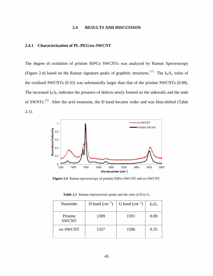
45
2.4 RESULTS AND DISCUSSION
2.4.1 Characterization of PL-PEG/ox-SWCNT
The degree of oxidation of pristine HiPCo SWCNTs was analyzed by Raman Spectroscopy
(Figure 2.4) based on the Raman signature peaks of graphitic structures.171
The ID/IG value of
the oxidized SWCNTs (0.35) was substantially larger than that of the pristine SWCNTs (0.08).
The increased ID/IG indicates the presence of defects newly formed on the sidewalls and the ends
of SWNTs.172
After the acid treatment, the D band became wider and was blue-shifted (Table
2.1).
Figure 2.4 Raman spectroscopy of pristine HiPco SWCNT and ox-SWCNT.
Table 2.1 Raman characteristic peaks and the ratio of D to G.
Nanotube D band (cm−1
) G band (cm−1
) ID/IG
Pristine
SWCNT
1309 1591 0.08
ox-SWCNT 1327 1596 0.35
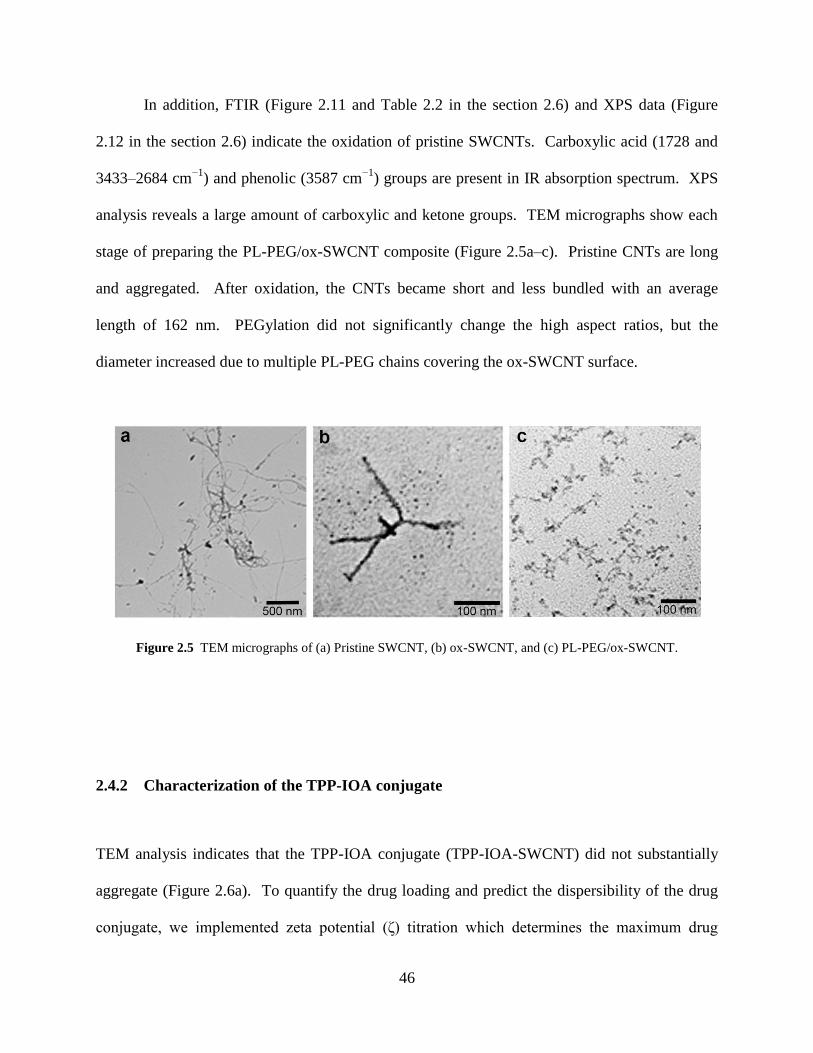
46
In addition, FTIR (Figure 2.11 and Table 2.2 in the section 2.6) and XPS data (Figure
2.12 in the section 2.6) indicate the oxidation of pristine SWCNTs. Carboxylic acid (1728 and
3433–2684 cm−1
) and phenolic (3587 cm−1
) groups are present in IR absorption spectrum. XPS
analysis reveals a large amount of carboxylic and ketone groups. TEM micrographs show each
stage of preparing the PL-PEG/ox-SWCNT composite (Figure 2.5a–c). Pristine CNTs are long
and aggregated. After oxidation, the CNTs became short and less bundled with an average
length of 162 nm. PEGylation did not significantly change the high aspect ratios, but the
diameter increased due to multiple PL-PEG chains covering the ox-SWCNT surface.
Figure 2.5 TEM micrographs of (a) Pristine SWCNT, (b) ox-SWCNT, and (c) PL-PEG/ox-SWCNT.
2.4.2 Characterization of the TPP-IOA conjugate
TEM analysis indicates that the TPP-IOA conjugate (TPP-IOA-SWCNT) did not substantially
aggregate (Figure 2.6a). To quantify the drug loading and predict the dispersibility of the drug
conjugate, we implemented zeta potential (ζ) titration which determines the maximum drug
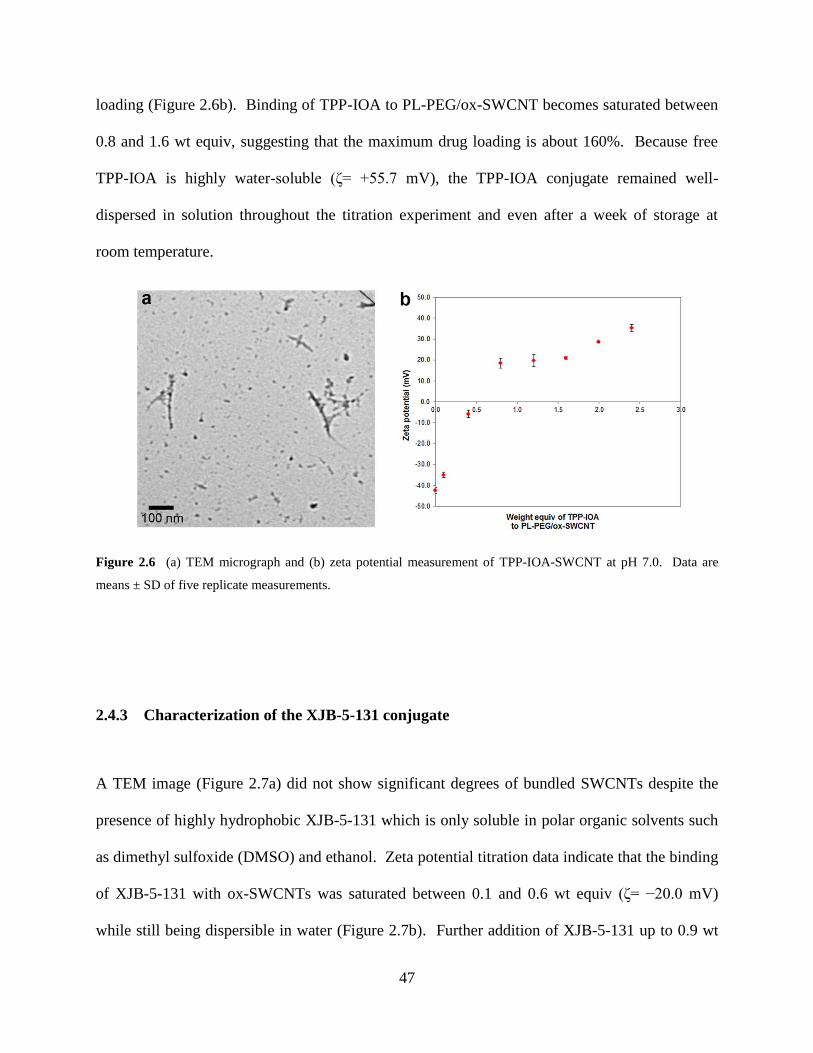
47
loading (Figure 2.6b). Binding of TPP-IOA to PL-PEG/ox-SWCNT becomes saturated between
0.8 and 1.6 wt equiv, suggesting that the maximum drug loading is about 160%. Because free
TPP-IOA is highly water-soluble (ζ= +55.7 mV), the TPP-IOA conjugate remained well-
dispersed in solution throughout the titration experiment and even after a week of storage at
room temperature.
Figure 2.6 (a) TEM micrograph and (b) zeta potential measurement of TPP-IOA-SWCNT at pH 7.0. Data are
means ± SD of five replicate measurements.
2.4.3 Characterization of the XJB-5-131 conjugate
A TEM image (Figure 2.7a) did not show significant degrees of bundled SWCNTs despite the
presence of highly hydrophobic XJB-5-131 which is only soluble in polar organic solvents such
as dimethyl sulfoxide (DMSO) and ethanol. Zeta potential titration data indicate that the binding
of XJB-5-131 with ox-SWCNTs was saturated between 0.1 and 0.6 wt equiv (ζ= −20.0 mV)
while still being dispersible in water (Figure 2.7b). Further addition of XJB-5-131 up to 0.9 wt
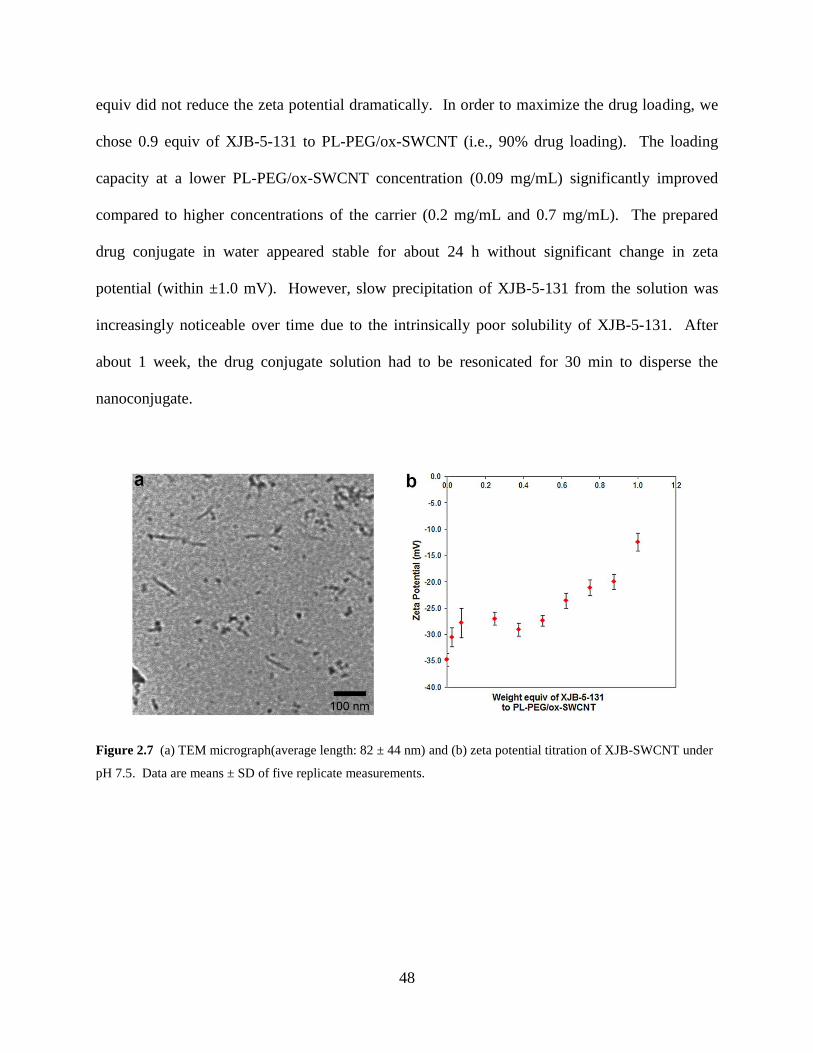
48
equiv did not reduce the zeta potential dramatically. In order to maximize the drug loading, we
chose 0.9 equiv of XJB-5-131 to PL-PEG/ox-SWCNT (i.e., 90% drug loading). The loading
capacity at a lower PL-PEG/ox-SWCNT concentration (0.09 mg/mL) significantly improved
compared to higher concentrations of the carrier (0.2 mg/mL and 0.7 mg/mL). The prepared
drug conjugate in water appeared stable for about 24 h without significant change in zeta
potential (within ±1.0 mV). However, slow precipitation of XJB-5-131 from the solution was
increasingly noticeable over time due to the intrinsically poor solubility of XJB-5-131. After
about 1 week, the drug conjugate solution had to be resonicated for 30 min to disperse the
nanoconjugate.
Figure 2.7 (a) TEM micrograph(average length: 82 ± 44 nm) and (b) zeta potential titration of XJB-SWCNT under
pH 7.5. Data are means ± SD of five replicate measurements.
49
2.4.4 In vivo results of the TPP-IOA conjugate
The TPP-IOA conjugate (TPP-IOA-SWCNT) was shown more effective as a radiomitigator than
free TPP-IOA. The therapeutic effect of TPP-IOA-SWCNT began to show after 12 h and the
mouse survival rate was markedly higher than untreated mice (Figure 2.8a). However, the
mitigating effect of TPP-IOA-SWCNT was very similar to that of free TPP-IOA up to 16 d and
slowly differed by ~15% after 20 d. The drug conjugate showed consistently higher rates
throughout the given time period whereas a lower survival rate of free TPP-IOA was observed in
the early stages of the experiment, which may be due to the high potency of free TPP-IOA. The
TPP-IOA-SWCNT conjugate clearly demonstrated a prolonged life span of TPP-IOA especially
over 1 h and maintained about a 35% margin over 24 h (Figure 2.8b).
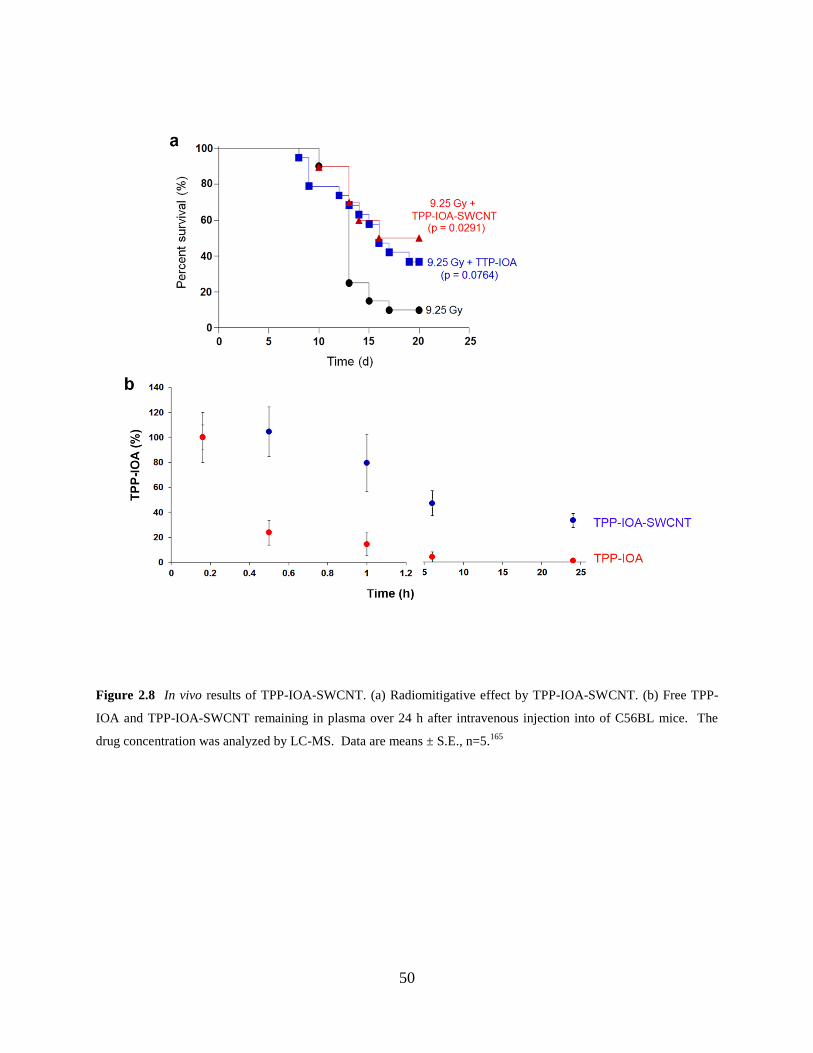
50
Figure 2.8 In vivo results of TPP-IOA-SWCNT. (a) Radiomitigative effect by TPP-IOA-SWCNT. (b) Free TPP-
IOA and TPP-IOA-SWCNT remaining in plasma over 24 h after intravenous injection into of C56BL mice. The
drug concentration was analyzed by LC-MS. Data are means ± S.E., n=5.165
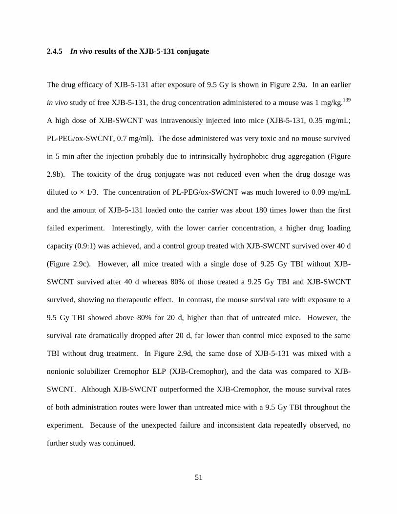
51
2.4.5 In vivo results of the XJB-5-131 conjugate
The drug efficacy of XJB-5-131 after exposure of 9.5 Gy is shown in Figure 2.9a. In an earlier
in vivo study of free XJB-5-131, the drug concentration administered to a mouse was 1 mg/kg.139
A high dose of XJB-SWCNT was intravenously injected into mice (XJB-5-131, 0.35 mg/mL;
PL-PEG/ox-SWCNT, 0.7 mg/ml). The dose administered was very toxic and no mouse survived
in 5 min after the injection probably due to intrinsically hydrophobic drug aggregation (Figure
2.9b). The toxicity of the drug conjugate was not reduced even when the drug dosage was
diluted to × 1/3. The concentration of PL-PEG/ox-SWCNT was much lowered to 0.09 mg/mL
and the amount of XJB-5-131 loaded onto the carrier was about 180 times lower than the first
failed experiment. Interestingly, with the lower carrier concentration, a higher drug loading
capacity (0.9:1) was achieved, and a control group treated with XJB-SWCNT survived over 40 d
(Figure 2.9c). However, all mice treated with a single dose of 9.25 Gy TBI without XJB-
SWCNT survived after 40 d whereas 80% of those treated a 9.25 Gy TBI and XJB-SWCNT
survived, showing no therapeutic effect. In contrast, the mouse survival rate with exposure to a
9.5 Gy TBI showed above 80% for 20 d, higher than that of untreated mice. However, the
survival rate dramatically dropped after 20 d, far lower than control mice exposed to the same
TBI without drug treatment. In Figure 2.9d, the same dose of XJB-5-131 was mixed with a
nonionic solubilizer Cremophor ELP (XJB-Cremophor), and the data was compared to XJB-
SWCNT. Although XJB-SWCNT outperformed the XJB-Cremophor, the mouse survival rates
of both administration routes were lower than untreated mice with a 9.5 Gy TBI throughout the
experiment. Because of the unexpected failure and inconsistent data repeatedly observed, no
further study was continued.
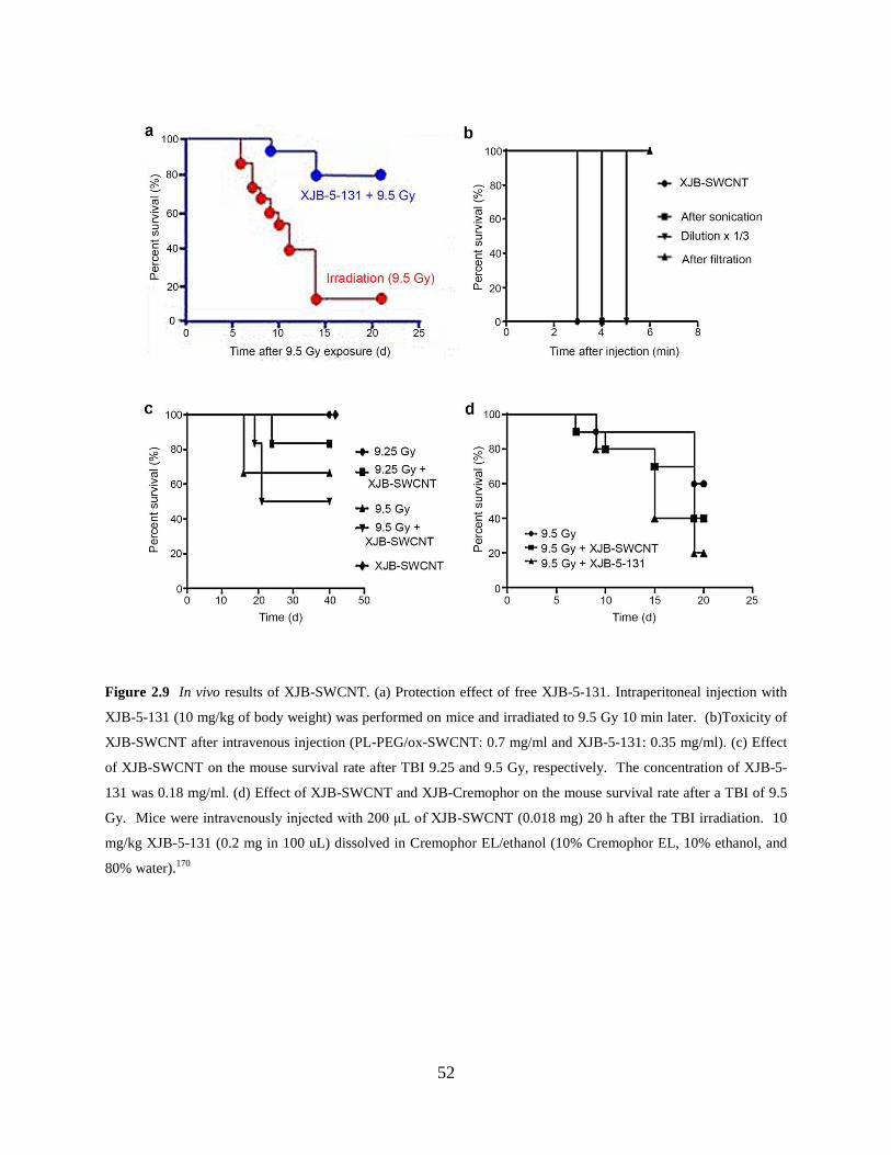
52
Figure 2.9 In vivo results of XJB-SWCNT. (a) Protection effect of free XJB-5-131. Intraperitoneal injection with
XJB-5-131 (10 mg/kg of body weight) was performed on mice and irradiated to 9.5 Gy 10 min later. (b)Toxicity of
XJB-SWCNT after intravenous injection (PL-PEG/ox-SWCNT: 0.7 mg/ml and XJB-5-131: 0.35 mg/ml). (c) Effect
of XJB-SWCNT on the mouse survival rate after TBI 9.25 and 9.5 Gy, respectively. The concentration of XJB-5-
131 was 0.18 mg/ml. (d) Effect of XJB-SWCNT and XJB-Cremophor on the mouse survival rate after a TBI of 9.5
Gy. Mice were intravenously injected with 200 μL of XJB-SWCNT (0.018 mg) 20 h after the TBI irradiation. 10
mg/kg XJB-5-131 (0.2 mg in 100 uL) dissolved in Cremophor EL/ethanol (10% Cremophor EL, 10% ethanol, and
80% water).170
53
2.5 CONCLUSION
The PL-PEG/ox-SWCNT composite was employed to improve the circulation time of
mitochondria targeting drugs TPP-IOA and XJB-5-131. The in vivo study of the TPP-IOA-
SWCNT conjugate revealed that the drug efficacy for 8–20 d after exposure to a TBI of 9.25 Gy
was marginally better than free TPP-IOA without an apparent sign of toxicity. The in vivo
experiments of the XJB-SWCNT conjugate did not show reasonable ground to employ a
nanocarrier. An interesting finding is that the drug loading capacity actually improved with a
low concentration of the nanocarrier. This result suggests that the high density of PEG chain
does not provide the high number of anchoring site for drugs, which seems counterintuitive. PL-
PEG successfully imparted biocompatibility to XJB-5-131, but failed to demonstrate the
nanocomposite as a reliable drug carrier.
54
2.6 SUPPORTING INFORMATION
2.6.1 Materials and instrumental
HiPco SWCNT was purchased from NanoIntegris®. Lyophilized human myeloperoxidase
(MPO) was received from Athens Research and Technology, INC. (Athens, GA, USA). N-
(aminopropylpolyethyleneglycol)carbamyl-disteaoyl phosphatidylethanolamine (DSPE-050PA)
was purchased from NOF Corporation. (Methyl-PEG12)3-PEG-NHS Ester (TMS(PEG)12) was
obtained from Thermo Scientific. N3-(2-hydroxy-2-nitroso-1-propylhydrazino)-1-propanamine
(Papa NONOate) was purchased from Cayman Chemical Company (Ann Arbor, MI). All other
chemicals were purchased from Sigma Aldrich, and were used without further purification. All
samples were prepared by dispersing dry solid in either nanopure water or phosphate buffer (pH
7.4).
Nanopure water was collected from Thermo Scientific BarnsteadTM NanopureTM.
Branson 5510 was used for ultrasonication. Thermo Scientific Savant SPD 1010 SpeedVac was
employed to dry aqueous samples (pressure: 5.6 Torr, temperature: 45 ˚C). The size distribution
and the morphology were analyzed with Transmission Electron Microscope (FEI-Morgani, 80
keV). Renishaw inVia Raman microscope was utilized to collect Raman spectra (laser λexcitation:
633 nm). Dried CNTs were drop-cast on a microscope slide. Spectra were collected with a 10
second exposure time and averaged across 5 scans per location. The collected spectra were
normalized to 1 with respect to the maximum intensity. MALDI mass spectra were recorded on
a Voyager-DE PRO Instrument. Zeta potential was measured using a Brookhaven ZetaPals at 25
˚C under specified conditions of pH. NMR spectra were acquired on a Bruker Avance III
400MHz NMR. Fourier Transform spectroscopy (FTIR) was performed employing an IR-
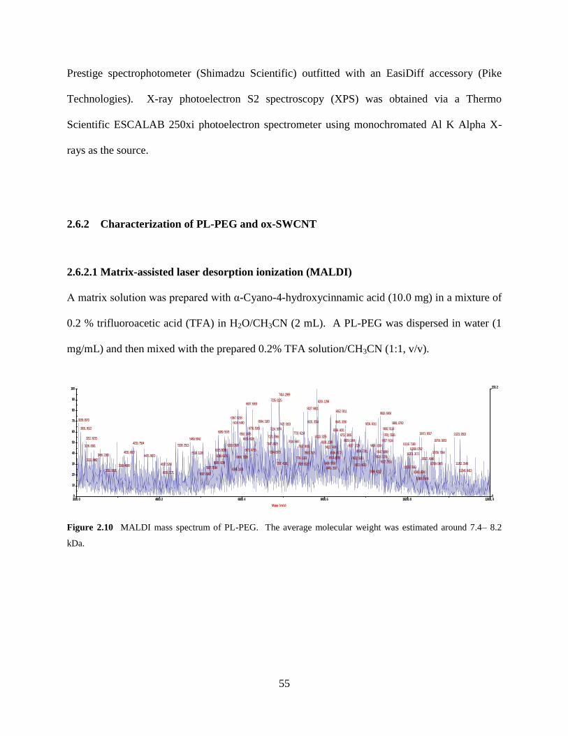
55
Prestige spectrophotometer (Shimadzu Scientific) outfitted with an EasiDiff accessory (Pike
Technologies). X-ray photoelectron S2 spectroscopy (XPS) was obtained via a Thermo
Scientific ESCALAB 250xi photoelectron spectrometer using monochromated Al K Alpha X-
rays as the source.
2.6.2 Characterization of PL-PEG and ox-SWCNT
2.6.2.1 Matrix-assisted laser desorption ionization (MALDI)
A matrix solution was prepared with α-Cyano-4-hydroxycinnamic acid (10.0 mg) in a mixture of
0.2 % trifluoroacetic acid (TFA) in H2O/CH3CN (2 mL). A PL-PEG was dispersed in water (1
mg/mL) and then mixed with the prepared 0.2% TFA solution/CH3CN (1:1, v/v).
Figure 2.10 MALDI mass spectrum of PL-PEG. The average molecular weight was estimated around 7.4– 8.2
kDa.
3000.0 4800.2 6600.4 8400.6 10200.8 12001.0
Mass (m/z)
0
153.2
0
10
20
30
40
50
60
70
80
90
100
% In
ten
sity
Voyager Spec #1=>BC=>NF0.7[BP = 2344.2, 2295]
7414.2999
7235.0125 8263.12986697.6969
8027.88118652.9011
9618.6464
6367.02383039.0970 6964.3100 8645.33908035.35546414.6480 9881.07609296.69117427.0163
6756.59053091.9522 9682.51147224.3874 8596.40016089.5578 7730.6214 10471.95576562.2478 11221.05029701.55068752.38858210.32557170.79663212.6215 6633.69295469.6942 10791.92638829.1984 9657.91347616.5667 8338.20894233.7504 7147.8929 10116.71886293.05085208.2513 9408.10198927.17293176.8301 7837.9905 8423.743810268.07626672.47336025.8038 9098.7391 9547.58997204.83734035.9017 10756.70648536.61727963.78255519.1138 10201.31713466.2160 4475.9673 6049.6676 9528.12356490.7109 8504.82957778.1333 9022.6351 10517.49463222.8462 9627.29145995.4234 8404.95587357.4191 11262.354810709.09707829.81224837.5296 9072.95703919.4699 10133.76605827.5514 8445.35976395.14743631.9501 11346.84139396.6212 10340.60404879.7171 5687.8982
10405.6904
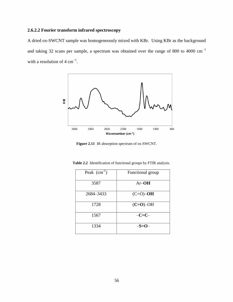
56
2.6.2.2 Fourier transform infrared spectroscopy
A dried ox-SWCNT sample was homogeneously mixed with KBr. Using KBr as the background
and taking 32 scans per sample, a spectrum was obtained over the range of 800 to 4000 cm−1
with a resolution of 4 cm−1
.
Figure 2.11 IR absorption spectrum of ox-SWCNT.
Table 2.2 Identification of functional groups by FTIR analysis.
Peak (cm-1
) Functional group
3587 Ar–OH
2684–3433 (C=O)–OH
1728 (C=O)–OH
1567 –C=C–
1334 –S=O–
57
2.6.2.3 X-ray photoelectron spectroscopy
The spot size of the sample was 400 μm (microns) prepared on an aluminum plate. Charge
compensation was provided by a low energy electron source and Ar+ ions. Survey scans were
collected using a pass energy of 150 eV, and high resolution scans were collected using a pass
energy of 50 eV. The average percentage indicates a mean obtained by analyzing three different
sample spots.
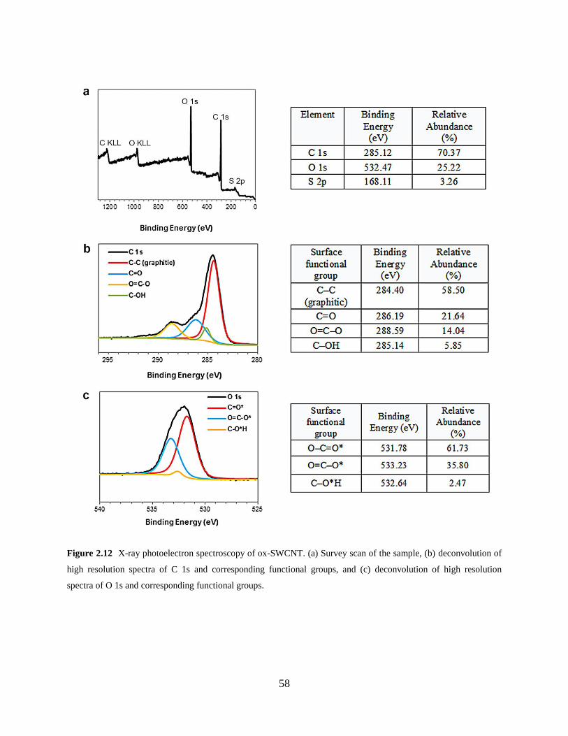
58
Figure 2.12 X-ray photoelectron spectroscopy of ox-SWCNT. (a) Survey scan of the sample, (b) deconvolution of
high resolution spectra of C 1s and corresponding functional groups, and (c) deconvolution of high resolution
spectra of O 1s and corresponding functional groups.
59
3.0 OXIDATIVE BIODEGRADATION STUDIES OF DOXORUBICIN-SINGLE
WALLED NANOTUBE DRUG CONJUGATE
3.1 CHAPTER PREFACE
Collaborative efforts were made to investigate the stability of a drug nanoconjugate in the
context of the innate immune response. A communication based on this work was published in
Nanoscale (DOI: 10.1039/C5NR00251F)173
and all figures were reproduced by permission of
The Royal Society of Chemistry. The Professor Michael Shurin group, Department of Pathology
at the University of Pittsburgh Medical Center, and the Professor Valerian Kagan group,
Department of Environmental and Occupational Health at the University of Pittsburgh conducted
the biological studies. W. Seo prepared a Doxorubicin nanoconjugate and performed ex vivo
experiments for the degradation of the drug nanoconjugate; Gallina V. Shurin conducted in vitro
experiments and analyzed data. W. Seo thanks Prof. Valerian E. Kagan and Prof. Michael R.
Shurin for their help in the course of manuscript preparation, and also acknowledges Alexandr A.
Kapralov for sharing the ex vivo experimental details of peroxynitrite-mediated degradation.
60
3.2 INTRODUCTION
Chapter 3 focuses on the oxidative degradation of a drug nanoconjugate by the components of
innate immune system and addresses issues implicated in drug circulation. The susceptibility of
the drug and the nanoconjugate to enzymatic reactions occurring in inflammatory cells can
shorten the circulation time and alter drug efficacy.174-175
This issue can be especially
problematic if a drug nanocarrier degrades upon immune response. As described in Chapter 1,
CNTs and PEGylated CNTs are able to undergo oxidative degradation.95,121
Thus drug carriers
consisting of those materials may need strategies to protect drug conjugates from oxidation and
facilitate controlled drug release.
For a proof-of-concept study, a Doxorubicin conjugate (DOX-SWCNT) is prepared for a
model system by noncovalent functionalization of an anticancer agent Doxorubicin (DOX) with
the PL-PEG/ox-SWCNT composite that was described in Chapter 2 (Figure 3.1). Several DOX
conjugates with slight modifications in the functional group and topology of PEG were
developed. In vivo studies of pharmacokinetics demonstrated that the use of PL-PEG/SWCNT
composites resulted in the prolonged circulation of DOX.137
Thus DOX-SWCNT conjugates
provide a good starting point for investigating the role of the immune system within the context
of drug circulation. Furthermore, knowledge of the degradation and stability of DOX under
various conditions will help us analyze results accurately.
Our study aims at investigating the lifespan of the drug and the degradation behavior of
DOX-SWCNT upon exposure to oxidative conditions mimicking oxidative burst of phagocytes.
For oxidative conditions, we chose (1) myeloperoxidase and hydrogen peroxide in the presence
of chloride (MPO/H2O2/Cl−) and (2) peroxynitrite (ONOO
−), which neutrophils and
macrophages spontaneously release to intra- and extracellular domains during the host-immune
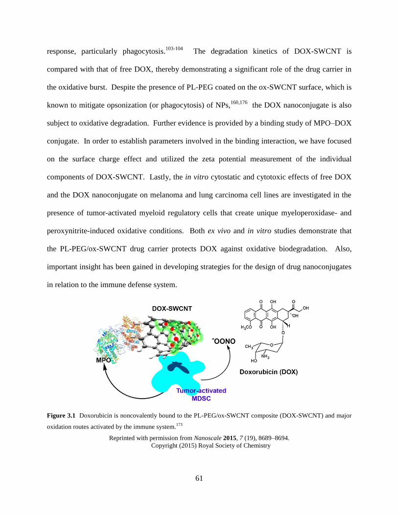
61
response, particularly phagocytosis.103-104
The degradation kinetics of DOX-SWCNT is
compared with that of free DOX, thereby demonstrating a significant role of the drug carrier in
the oxidative burst. Despite the presence of PL-PEG coated on the ox-SWCNT surface, which is
known to mitigate opsonization (or phagocytosis) of NPs,160,176
the DOX nanoconjugate is also
subject to oxidative degradation. Further evidence is provided by a binding study of MPO–DOX
conjugate. In order to establish parameters involved in the binding interaction, we have focused
on the surface charge effect and utilized the zeta potential measurement of the individual
components of DOX-SWCNT. Lastly, the in vitro cytostatic and cytotoxic effects of free DOX
and the DOX nanoconjugate on melanoma and lung carcinoma cell lines are investigated in the
presence of tumor-activated myeloid regulatory cells that create unique myeloperoxidase- and
peroxynitrite-induced oxidative conditions. Both ex vivo and in vitro studies demonstrate that
the PL-PEG/ox-SWCNT drug carrier protects DOX against oxidative biodegradation. Also,
important insight has been gained in developing strategies for the design of drug nanoconjugates
in relation to the immune defense system.
Figure 3.1 Doxorubicin is noncovalently bound to the PL-PEG/ox-SWCNT composite (DOX-SWCNT) and major
oxidation routes activated by the immune system.173
Reprinted with permission from Nanoscale 2015, 7 (19), 8689–8694.
Copyright (2015) Royal Society of Chemistry
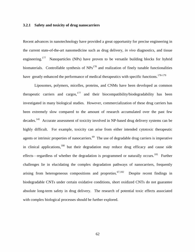
62
3.2.1 Safety and toxicity of drug nanocarriers
Recent advances in nanotechnology have provided a great opportunity for precise engineering in
the current state-of-the-art nanomedicine such as drug delivery, in vivo diagnostics, and tissue
engineering.177
Nanoparticles (NPs) have proven to be versatile building blocks for hybrid
biomaterials. Controllable synthesis of NPs178
and realization of finely tunable functionalities
have greatly enhanced the performance of medical therapeutics with specific functions.178-179
Liposomes, polymers, micelles, proteins, and CNMs have been developed as common
therapeutic carriers and cargos,177
and their biocompatibility/biodegradability has been
investigated in many biological studies. However, commercialization of these drug carriers has
been extremely slow compared to the amount of research accumulated over the past few
decades.141
Accurate assessment of toxicity involved in NP-based drug delivery systems can be
highly difficult. For example, toxicity can arise from either intended cytotoxic therapeutic
agents or intrinsic properties of nanocarriers.69
The use of degradable drug carriers is imperative
in clinical applications,180
but their degradation may reduce drug efficacy and cause side
effects—regardless of whether the degradation is programmed or naturally occurs.181
Further
challenges lie in elucidating the complex degradation pathways of nanocarriers, frequently
arising from heterogeneous compositions and propreties.67,182
Despite recent findings in
biodegradable CNTs under certain oxidative conditions, short oxidized CNTs do not guarantee
absolute long-term safety in drug delivery. The research of potential toxic effects associated
with complex biological processes should be further explored.
63
3.2.2 Innate immune responses to nanocarriers and pharmacokinetic implications
NPs with small sizes and high surface area to volume ratios provide excellent platforms for high
reactivity in living organisms.145
Utilization of nanocarriers allows for better carrier-target
interactions (e.g., enhanced permeation and retention (EPR) effect) and efficient cellular/tissue
uptakes.153
However, the intrinsically high surface energy of NPs may cause major problems in
pharmacokinetics: (1) low solubility arising from the formation of aggregates, (2) nonspecific
binding with plasma proteins and deterioration by other chemical species that exist in the blood
and lymphatics,152
(3) premature drug loss due to size-dependent phagocytosis by innate immune
cells during circulation,183
and (4) fast clearance through reticuloendothelial systems (RES) such
as liver and spleen.152
Despite the enhanced permeability and retention (EPR) effect of NPs,
generally the rate of drug permeation through cell membranes was found extremely low.184
To
improve clinical efficacy, especially circulation, optimization of the thermodynamic properties
(e.g., surface free energy) in physiological conditions and investigation of relevant parameters
(e.g., size, shape, and surface charge) in relation to clearance routes through different organs are
crucial in the early stage of developing new drug delivery systems (Figure 3.2).152,175
All these
properties interplay with each other, generate fundamentally complex problems, and eventually
converge into the issue of biocompatibility and biodegradation regulated by the FDA.180
Behind the success of targeted drug delivery, the issue of designing NPs resistant toward
the innate immune system has been only marginally addressed. Because the human body reacts
to drug conjugates nonspecifically, immune responses vary with the reactivity and toxicity of
individual drugs and nanocarriers.185
As a consequence, fewer drug molecules may reach the
target than administered doses, thereby dramatically altering the original pharmacokinetics
properties of drugs.145,175
In addition, harmful self-immune responses such as inflammation or
64
even infectious diseases could be induced.186
White blood cells (leukocytes), an essential
component in innate immunity, and various tissues contain neutrophils (polymorphonuclear
phagocytes) and monocytes/macrophages (typically Kupffer cells or macrophages of the
liver).174,176
Upon cellular ingestion of invading organisms, specific opsonin proteins present in
serum, particularly C3, C4, and C5, and immunoglobulins, are recognized in the phagocytosis.176
Neutrophils are ready to activate the immune response in the circulating blood, whereas
macrophages can fight against toxins and infectious agents only in tissues.187
In order to initiate
phagocytosis in tissues, neutrophils in the blood migrate to the tissue and are attracted to an
inflammatory area by chemotaxis—a chemical signaling process.186
Because neutrophils are
most abundant among white blood cells and can be very effective for killing pathogens within a
short time period (about 3–4 d),101
evaluation of the stability of drug conjugates toward
neutrophils is critical. In contrast to neutrophils, the immune response activated by macrophages
persists over weeks of chronic inflammation.107
Although the oxidizing power of peroxynitrite is
weaker than the MPO-catalyzed oxidative cycle, the long-term immune response and
inflammation can sufficiently influence cellular and tissue environments as well as drug
conjugates.
With growing interests in the nonspecific clearance of therapeutic NPs promoted by self-
immune responses, a few recent studies have demonstrated that chemical modification of the NP
surface may alter their properties and prevent a shortened life span of drug delivery systems and
premature drug release.188
For example, a synthetic molecular ligand incorporated onto the
surface of a nanocarrier interferes with molecular recognition and signaling processes at the
initial stage of phagocytosis.188
Addition of a polymer that can alter C3 cascade complement
system reduces nonspecific binding between nanocarriers and hepatic macrophages.189
These
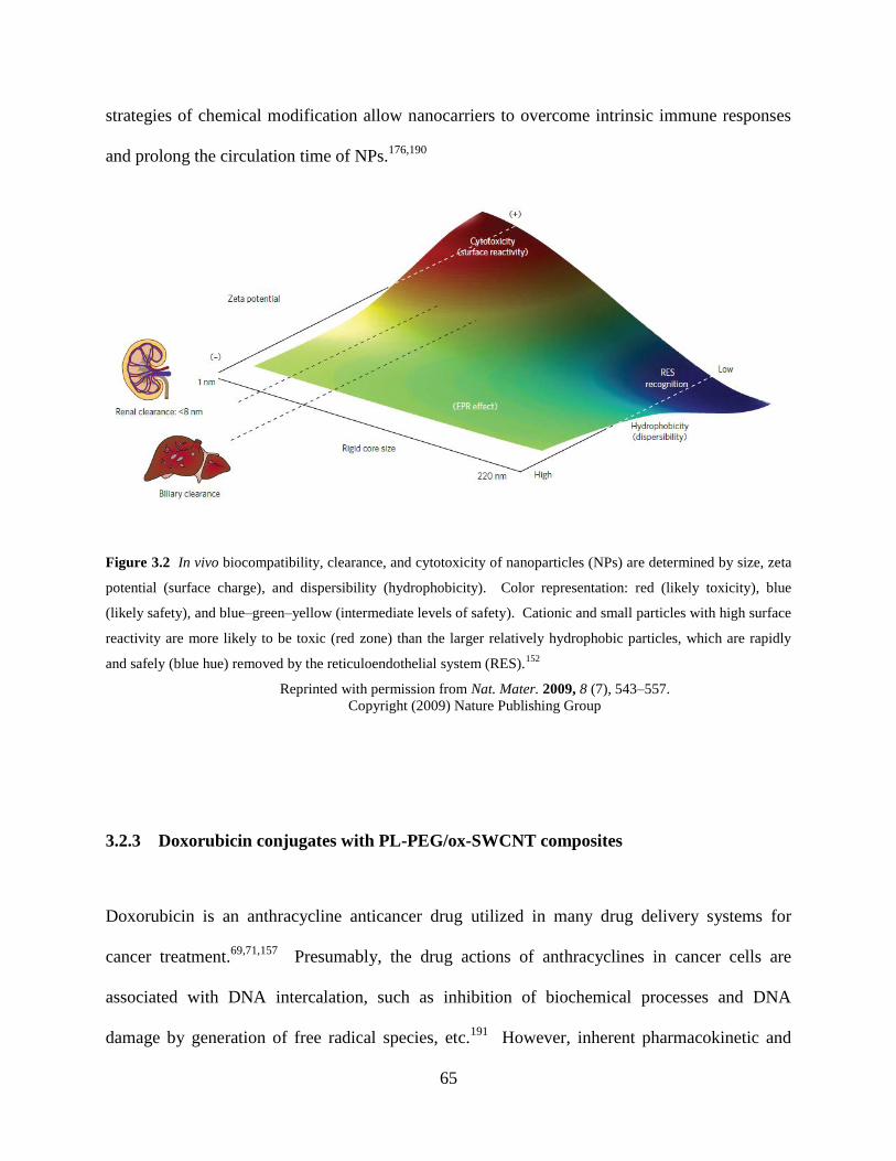
65
strategies of chemical modification allow nanocarriers to overcome intrinsic immune responses
and prolong the circulation time of NPs.176,190
Figure 3.2 In vivo biocompatibility, clearance, and cytotoxicity of nanoparticles (NPs) are determined by size, zeta
potential (surface charge), and dispersibility (hydrophobicity). Color representation: red (likely toxicity), blue
(likely safety), and blue–green–yellow (intermediate levels of safety). Cationic and small particles with high surface
reactivity are more likely to be toxic (red zone) than the larger relatively hydrophobic particles, which are rapidly
and safely (blue hue) removed by the reticuloendothelial system (RES).152
Reprinted with permission from Nat. Mater. 2009, 8 (7), 543–557.
Copyright (2009) Nature Publishing Group
3.2.3 Doxorubicin conjugates with PL-PEG/ox-SWCNT composites
Doxorubicin is an anthracycline anticancer drug utilized in many drug delivery systems for
cancer treatment.69,71,157
Presumably, the drug actions of anthracyclines in cancer cells are
associated with DNA intercalation, such as inhibition of biochemical processes and DNA
damage by generation of free radical species, etc.191
However, inherent pharmacokinetic and
66
metabolic changes resulting in drug resistance and toxicity, notably cardiotoxicity, are well-
documented in many occasions.191-192
Various properties of free Doxorubicin have been
extensively studied in addition to the pharmacokinetics and side effects,193-194
such as photolytic
and enzymatic degradations192-193
and stability in infusion fluids.195
Among many examples, the
one-electron promoted redox cycle of quinone/semiquinone formation has been considered
important due to the generation of a strong oxidant hydroxyl radical and oxidative damage in
cells.191
Such paradigms as target/nontarget delivery and controlled release have been employed
to improve the clinical efficacy of free DOX. Liposome carrier-based commercial products such
as Doxil® and Myocet® have shown therapeutic indices far better than free DOX.196
A great
number of CNM-based DOX conjugates have been developed.60,69
The pharmacokinetics (i.e.,
biodistribution and clearance) and toxicity of noncovalently functionalized DOX-SWCNT
conjugates and PL-PEG/ox-SWCNT carriers were studied previously.137,197
The surface density
of PL-PEG coated on a SWCNT carrier was found about 10% of the total area of SWCNT.154
Generally, the DOX loading capacity of 1–4 mg can be achieved with 1 mg of SWCNT-based
carriers.137
The binding energy of DOX to HiPco SWCNTs commonly used in drug delivery
was estimated to be approximately 14 kcal/mol in water.154
Drug release was found pH-
dependent; at pH 5.5, about 40% of DOX was released from the carrier over 1 day.154
DOX-
SWCNT conjugates were demonstrated to be safe in vivo without apparent toxicity over 3–4
months when drug loading of 2.5 mg/mL (the wt of DOX per SWCNT carrier) was achieved.197-
198 The intravenously administered DOX-SWCNT accumulated largely in the liver and the
spleen after 6 h in mice.198
While increasing the half-life time of DOX, the drug uptake by
tumors was doubled with DOX-SWCNT and was far better than Doxil.137
The improved

67
therapeutic efficacy was attributed mainly to the longer circulation half-life time.137
When only
the PL-PEG/SWCNT carrier was tested, the nanocomposite began in vivo clearance from the
liver through biliary excretion without significant adverse effects.197
68
3.3 EXPERIMENTAL
3.3.1 Preparation of the Doxorubicin conjugate (DOX-SWCNT)
PL-PEG/ox-SWCNT was prepared using the same method as described in Chapter 3.
Doxorubicin (4.8 mg) was dissolved in 10 mL of phosphate buffer (0.1 M, pH 8.2). The DOX
solution was sonicated for 30 min and was stirred overnight. After thorough washing with the
same buffer solution through centrifugation, the amount of DOX wash-off was calculated from a
UV-Vis calibration curve. The calculation showed that about 2.3 mg of DOX was bound to 3.0
mg of PL-PEG/ox-SWCNT, which corresponds to a 77% of drug loading. This estimation differs
by 23% from the UV-Vis titration (Figure 3.10).
3.3.2 Ex vivo oxidation of the Doxorubicin conjugate
3.3.2.1 Myeloperoxide-catalyzed degradation
Each DOX-SWCNT sample was prepared by dispersing 0.03 mg of DOX-SWCNT in 720 μL of
phosphate buffer (pH 7.4, 0.1 M). The concentration of free DOX was 0.02 mg/mL. Stock
solutions of DTPA and NaCl were added to the DOX-SWCNT solution, and their final
concentrations were adjusted to 0.38 mM and 0.14 M respectively. The concentration of DOX-
SWCNT was 0.04 mg/mL. For the experiment of +MPO/+H2O2/+Cl−, 4.4 μg of MPO was
added every 24 h, and the H2O2 stock solution (18.75 mM) was added every 4 h (total volume of
30 μL per day). For −MPO/−H2O2/+Cl−, the same amount of the pH 7.4 buffer solution was
added. The samples were stored in a standard cell culture incubator at 37 ˚C. For UV-Vis-NIR
69
analysis, samples were cooled at ambient temperature for about 10 min. Each spectrum was
collected with 700 μL of a sample solution in a quartz sample holder (path length: 1 cm), and
further absorbance was recorded after each new addition of H2O2. A 0.02 mg/mL PL-PEG/ox-
SWCNT solution was prepared in the same buffer condition. Then the same procedure was used
to monitor the degradation of the nanocarrier. TEM analysis of degraded PL-PEG/ox-SWCNT
samples were prepared by diluting the original 1:20 or 1:50 times with ethanol, and 3 μL of the
diluted solution was placed on a lacey carbon copper grid and then permitted to dry in ambient
conditions over 24 h.
3.3.2.2 Peroxynitrite-mediated degradation
Each DOX-SWCNT sample had a concentration of 0.03 mg of DOX-SWCNT in 808 μL of
phosphate buffer (pH 7.4, 0.1 M), and 0.02 mg/mL of free DOX was prepared in the same
buffer. Stock solutions of all other reagents were prepared every day. Then 7.5 μL of a xanthine
oxidase (XO) solution (×50 diluted from the original enzyme) containing 0.15–0.3 mU of XO,
was added once per day, followed by additions of 7.5 μL of xanthine solution (7.0 mM) and 7.5
μL of a PAPA NONOate solution (3.5 mM) every 2 h (total 6 times per day). Due to the dilution
effect, the concentrations of both xanthine and PAPA NONOate solutions were raised after 6
additions, maintaining the same amount of each reagent relative to the total volume of the DOX-
SWCNT solution. After incubation over a given time period, all the samples were filtered using
Amicon centrifuge filters (size: 1,000 Da). The filtrate and the concentrate were separately
collected by ultracentrifugation (14,000 × g, 10 min), and the concentrate was further diluted in
phosphate buffer (0.1M, pH 7.4) for proper analysis. Then fluorescence emission spectroscopy
(λexcitation=488 nm, λemission=592 nm) was utilized to measure the concentration of DOX-SWCNT
within a linear calibration range at room temperature. Due to some loss of DOX-SWCNT after
70
the ultracentrifugal filtration, a separate test determining the average recovery rate of DOX-
SWCNT was performed to estimate the concentration accurately. The average recovery rate of
five replicated samples was 62 ± 4 (%) from the original amount.
3.3.3 Zeta potential of MPO and DOX-SWCNT
The laser of the zeta potential analyzer was set at 532 nm. The zeta potential of unbound pure
MPO was measured separately, which gave a negative potential (−9.0 ± 1.7 mV). A rapid color
change to a very bright yellow upon the laser irradiation suggests the photosensitive heme of
MPO.199
After each titration, a sample containing DOX-SWCNT and MPO solutions was placed
under ambient temperature and pressure over 1 h until their binding reached equilibrium, and
then zeta potential was recorded. For the titration sample, solutions of DOX-SWCNT (0.3
mg/mL) and MPO were prepared in a mixture of nanopure water and 0.05 M, pH 7.4 phosphate
buffer (17:1, v/v).
3.3.4 In vitro oxidation of the Doxorubicin conjugate
Pathogen-free C57BL/6 mice (7–8 week old) obtained from Jackson Labs (Bar Harbor, ME,
USA) were individually housed and acclimated for 2 weeks. Animals were supplied with water
and food ad libitum and housed under controlled light, temperature, and humidity conditions.
All animal studies were conducted under a protocol approved by the Institutional Animal Care
and Use Committee. Data were analyzed using one-way ANOVA and Student unpaired t-test
71
with Welch's correction for unequal variances. All experiments were either done in triplicates or
repeated at least twice, and the results were presented as means ± SEM (standard error of the
mean). P values of < 0.05 were considered to be statistically significant.
B16 melanoma cells were obtained from American Type Culture Collection (ATCC,
Manassas, VA, USA) and maintained in RPMI 1640 medium that was supplemented with 2 mM
L-glutamine, 100 U/ml penicillin, 100 μg/ml streptomycin, 10 mM HEPES, 10% heat-
inactivated FBS, 0.1 mM nonessential amino acids, and 1 mM sodium pyruvate (Invitrogen Life
Technologies, Inc., Grand Island, NY, USA). Tumor conditioned medium was collected from
sub-confluent cultures by centrifugation (300 g, 15 min). The cell-free supernatant was
collected, aliquoted, and used to treat MDSC.
For MDSC generation, bone marrow cells from tibia were isolated, filtered through a 70
μm cell strainer, and red blood cells were lysed with lysing buffer (155 mM NH4Cl in 10 mM
Tris-HCl buffer pH 7.5, 25°C) for 3 min. After RBC lysis, cells were washed and used for
MDSC sorting. CD11b+ Gr-1+ MDSC were isolated from the bone marrow cell suspensions by
magnetic cell sorting using a mouse MDSC Isolation Kit (MACS, Miltenyi Biotec, Auburn, CA,
USA) according to the manufacturer’s instructions. Isolated MDSC were cultured in
supplemented RPMI 1640 medium with 25% (v/v) B16 conditioned medium for 48 h to generate
tumor-activated MDSC expressing high levels of MPO.
Cell proliferation assay 3LL cells were labeled with CellTracker™ Orange CMTMR (5-
(and-6)-(((4-chloromethyl)benzoyl)amino) tetramethylrhodamine) (Molecular Probes) and co-
incubated with free DOX and DOX-SWCNT in the presence of tumor-activated MDSC. Co-
incubation of 3LL cells with SWCNT, MDSC or both served as controls. After 24 h of
incubation, the number of labeled 3LL cells was determined by flow cytometry (FacsCalibur)

72
events calculated for 1 min. Increased number of cells (vs. control medium group) indicates an
increase in cell proliferation, while the lower cell number reflects cytotoxic (cell death) and/or
cytostatic (inhibition of cell proliferation) effects on tumor cells.
73
3.4 RESULTS AND DISCUSSION
3.4.1 Characterization of Doxorubicin and nanocarrier
DOX-SWCNT was synthesized following a published procedure.137,197
DOX-SWCNT was
prepared with the PL-PEG/ox-SWCNT composite that was described in Chapter 2 (Figure 3.3a
and b). Although most of the drug conjugate particles maintain high aspect ratios, agglomerates
are relatively abundant.
UV-Vis-NIR absorption spectra confirm the presence of each component of the drug
conjugate (Figure 3.3c). The suppressed S11 optical transitions near 870–1100 nm are
characteristic of oxidized HiPco SWCNTs,200
in which the broad absorption band constitutes the
residual peaks of numerous chiral species (n,m).15
A slightly red-shifted DOX absorption
maximum at 495 nm from the free DOX absorption (480 nm) is indicative of noncovalent
adsorption of drug molecules on the ox-SWCNT surface,201
which was further demonstrated by
the quenched fluorescence emission of DOX by mainly π–π stacking154
at 555 and 595 nm
(Figure 3.3d). The drug loading capacity of DOX was measured by titrations using UV-Vis
absorption spectroscopy (Figure. 3.10, Ch. 3.6) and zeta potential analysis under pH 7.0 (Figure
3.11, Ch. 3.6). The binding ratio of DOX to the nanocarrier (bound DOX/nanocarrier, w/w) was
found to be approximately 1:1.
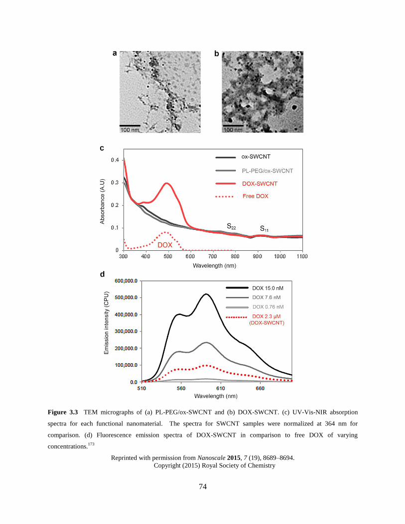
74
Figure 3.3 TEM micrographs of (a) PL-PEG/ox-SWCNT and (b) DOX-SWCNT. (c) UV-Vis-NIR absorption
spectra for each functional nanomaterial. The spectra for SWCNT samples were normalized at 364 nm for
comparison. (d) Fluorescence emission spectra of DOX-SWCNT in comparison to free DOX of varying
concentrations.173
Reprinted with permission from Nanoscale 2015, 7 (19), 8689–8694.
Copyright (2015) Royal Society of Chemistry
75
3.4.2 Ex vivo oxidative degradation of Doxorubicin and nanocarrier
3.4.2.1 Myeloperoxidase-catalyzed degradation
The degradation profiles of ox-SWCNT and DOX in phosphate buffer solution (0.1 M, pH 7.4)
were investigated by monitoring spectral changes in UV-Vis-NIR absorption spectroscopy. Each
sample contained NaCl (0.14 M) as a chloride source and diethylenetriamine pentaacetic acid
(DTPA) as a chelating agent coordinating with residual transition metal catalyst ions present in
the commercial HiPco CNTs. The peroxidase-catalyzed oxidation cycle was initiated by
addition of an aliquot of H2O2, which produced hypochlorous acid/hypochlorite (HOCl/OCl−)
equilibrating at pH 7.4 and reactive intermediate species.110,119
Hypochlorite (OCl−) can further
induce oxidation, and MPO-I and MPO-II, each of which drives one-electron oxidation,202
promote the formation of reactive radical intermediates and electron transfer reactions.
The samples were incubated at 37 °C, and the resulting spectral changes were recorded
periodically at room temperature. In the presence of MPO/H2O2/Cl−, Figure. 3.4a and b show
decreases in absorbance of DOX at 495 nm and the S11 region (900–1100 nm) of ox-SWCNT.
The absorption profile of the residual peaks near 950 nm changed significantly. Likewise, the
NIR absorbance of PL-PEG/ox-SWCNT (no drug) decreased (Figure 3.4c), indicating that the
nanotube surface coated with the PL-PEG had also undergone oxidative degradation, as
demonstrated by TEM (Figure 3.4d–i). This result is in good agreement with previous
degradation studies of PEG-SWCNTs that were noncovalently functionalized with PEGs of
various molecular weights (ca. 600–10 000 Da).95,121
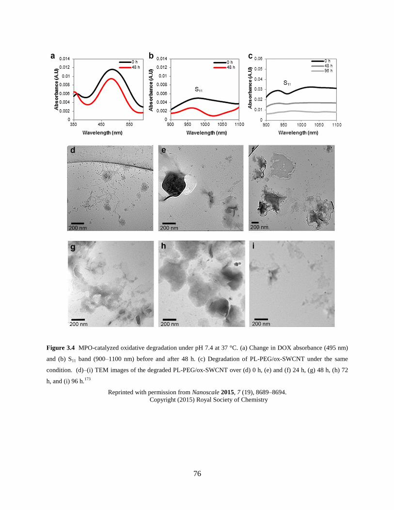
76
Figure 3.4 MPO-catalyzed oxidative degradation under pH 7.4 at 37 °C. (a) Change in DOX absorbance (495 nm)
and (b) S11 band (900–1100 nm) before and after 48 h. (c) Degradation of PL-PEG/ox-SWCNT under the same
condition. (d)–(i) TEM images of the degraded PL-PEG/ox-SWCNT over (d) 0 h, (e) and (f) 24 h, (g) 48 h, (h) 72
h, and (i) 96 h.173
Reprinted with permission from Nanoscale 2015, 7 (19), 8689–8694.
Copyright (2015) Royal Society of Chemistry
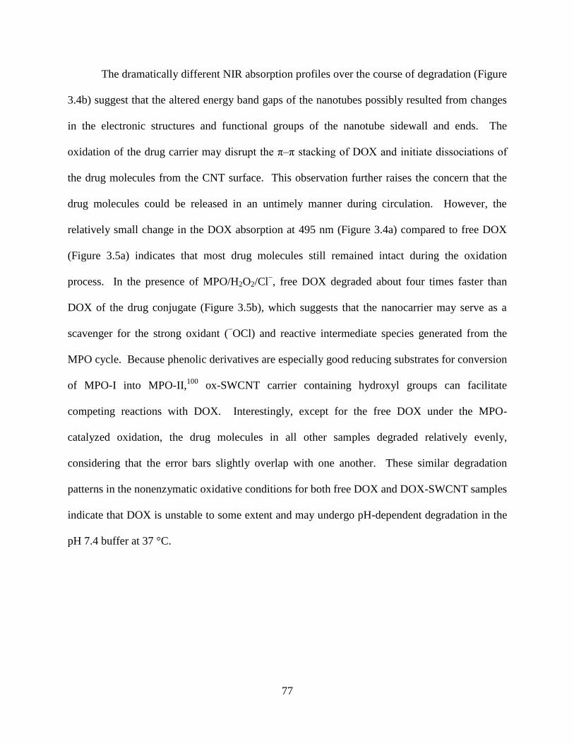
77
The dramatically different NIR absorption profiles over the course of degradation (Figure
3.4b) suggest that the altered energy band gaps of the nanotubes possibly resulted from changes
in the electronic structures and functional groups of the nanotube sidewall and ends. The
oxidation of the drug carrier may disrupt the π–π stacking of DOX and initiate dissociations of
the drug molecules from the CNT surface. This observation further raises the concern that the
drug molecules could be released in an untimely manner during circulation. However, the
relatively small change in the DOX absorption at 495 nm (Figure 3.4a) compared to free DOX
(Figure 3.5a) indicates that most drug molecules still remained intact during the oxidation
process. In the presence of MPO/H2O2/Cl−, free DOX degraded about four times faster than
DOX of the drug conjugate (Figure 3.5b), which suggests that the nanocarrier may serve as a
scavenger for the strong oxidant (−OCl) and reactive intermediate species generated from the
MPO cycle. Because phenolic derivatives are especially good reducing substrates for conversion
of MPO-I into MPO-II,100
ox-SWCNT carrier containing hydroxyl groups can facilitate
competing reactions with DOX. Interestingly, except for the free DOX under the MPO-
catalyzed oxidation, the drug molecules in all other samples degraded relatively evenly,
considering that the error bars slightly overlap with one another. These similar degradation
patterns in the nonenzymatic oxidative conditions for both free DOX and DOX-SWCNT samples
indicate that DOX is unstable to some extent and may undergo pH-dependent degradation in the
pH 7.4 buffer at 37 °C.
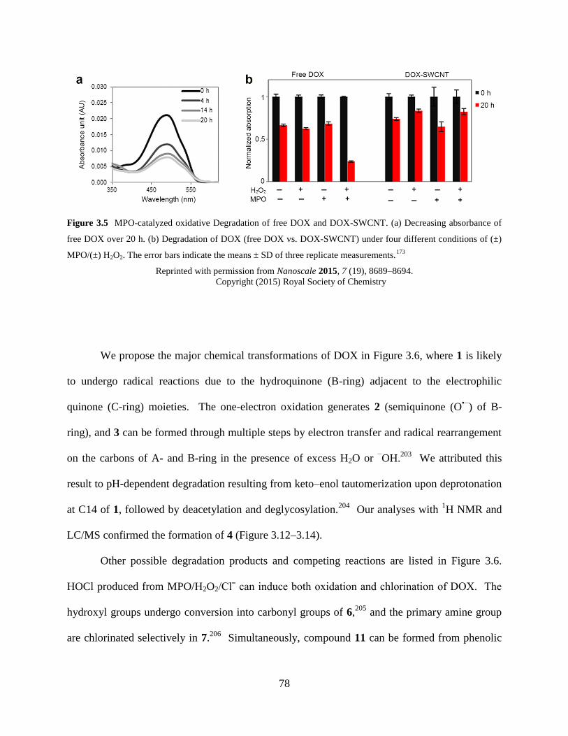
78
Figure 3.5 MPO-catalyzed oxidative Degradation of free DOX and DOX-SWCNT. (a) Decreasing absorbance of
free DOX over 20 h. (b) Degradation of DOX (free DOX vs. DOX-SWCNT) under four different conditions of (±)
MPO/(±) H2O2. The error bars indicate the means ± SD of three replicate measurements.173
Reprinted with permission from Nanoscale 2015, 7 (19), 8689–8694.
Copyright (2015) Royal Society of Chemistry
We propose the major chemical transformations of DOX in Figure 3.6, where 1 is likely
to undergo radical reactions due to the hydroquinone (B-ring) adjacent to the electrophilic
quinone (C-ring) moieties. The one-electron oxidation generates 2 (semiquinone (O•−
) of B-
ring), and 3 can be formed through multiple steps by electron transfer and radical rearrangement
on the carbons of A- and B-ring in the presence of excess H2O or −OH.
203 We attributed this
result to pH-dependent degradation resulting from keto–enol tautomerization upon deprotonation
at C14 of 1, followed by deacetylation and deglycosylation.204
Our analyses with 1H NMR and
LC/MS confirmed the formation of 4 (Figure 3.12–3.14).
Other possible degradation products and competing reactions are listed in Figure 3.6.
HOCl produced from MPO/H2O2/Clˉ can induce both oxidation and chlorination of DOX. The
hydroxyl groups undergo conversion into carbonyl groups of 6,205
and the primary amine group
are chlorinated selectively in 7.206
Simultaneously, compound 11 can be formed from phenolic
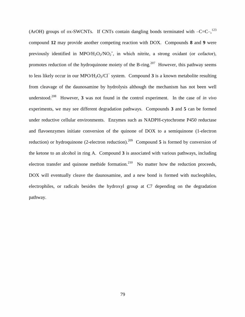
79
(ArOH) groups of ox-SWCNTs. If CNTs contain dangling bonds terminated with –C=C–,123
compound 12 may provide another competing reaction with DOX. Compounds 8 and 9 were
previously identified in MPO/H2O2/NO2ˉ, in which nitrite, a strong oxidant (or cofactor),
promotes reduction of the hydroquinone moiety of the B-ring.207
However, this pathway seems
to less likely occur in our MPO/H2O2/Cl− system. Compound 3 is a known metabolite resulting
from cleavage of the daunosamine by hydrolysis although the mechanism has not been well
understood.208
However, 3 was not found in the control experiment. In the case of in vivo
experiments, we may see different degradation pathways. Compounds 3 and 5 can be formed
under reductive cellular environments. Enzymes such as NADPH-cytochrome P450 reductase
and flavoenzymes initiate conversion of the quinone of DOX to a semiquinone (1-electron
reduction) or hydroquinone (2-electron reduction).209
Compound 5 is formed by conversion of
the ketone to an alcohol in ring A. Compound 3 is associated with various pathways, including
electron transfer and quinone methide formation.210
No matter how the reduction proceeds,
DOX will eventually cleave the daunosamine, and a new bond is formed with nucleophiles,
electrophiles, or radicals besides the hydroxyl group at C7 depending on the degradation
pathway.
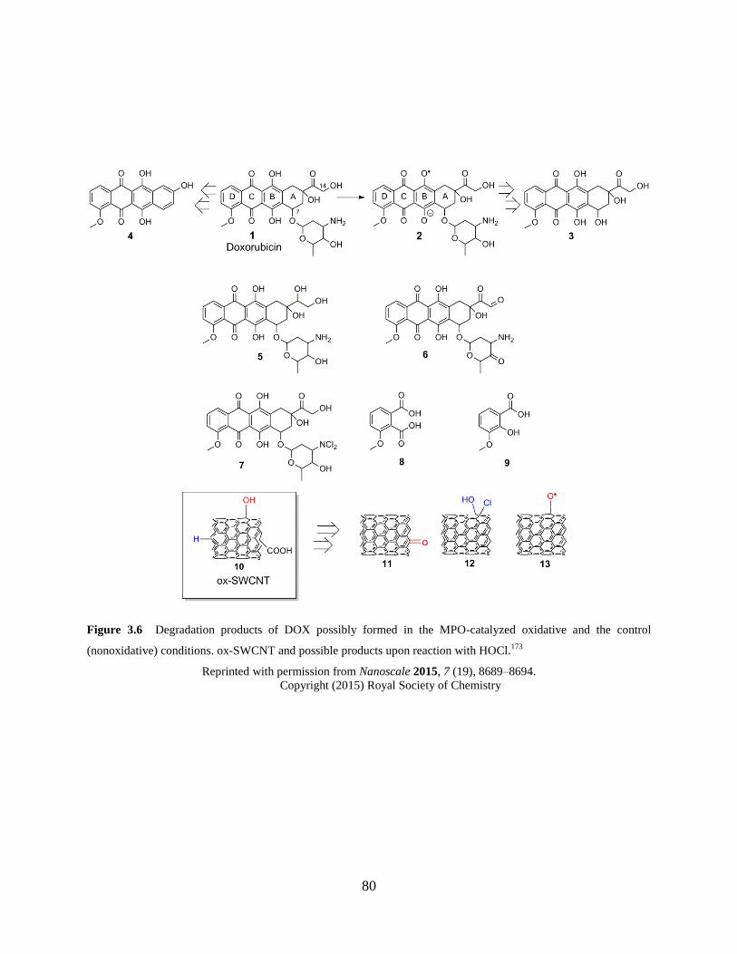
80
Figure 3.6 Degradation products of DOX possibly formed in the MPO-catalyzed oxidative and the control
(nonoxidative) conditions. ox-SWCNT and possible products upon reaction with HOCl.173
Reprinted with permission from Nanoscale 2015, 7 (19), 8689–8694.
Copyright (2015) Royal Society of Chemistry
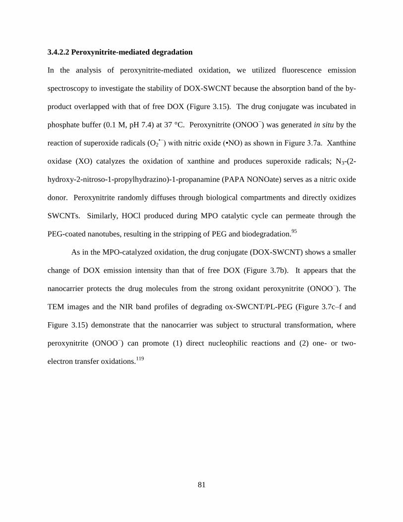
81
3.4.2.2 Peroxynitrite-mediated degradation
In the analysis of peroxynitrite-mediated oxidation, we utilized fluorescence emission
spectroscopy to investigate the stability of DOX-SWCNT because the absorption band of the by-
product overlapped with that of free DOX (Figure 3.15). The drug conjugate was incubated in
phosphate buffer (0.1 M, pH 7.4) at 37 °C. Peroxynitrite (ONOO−) was generated in situ by the
reaction of superoxide radicals (O2•−
) with nitric oxide (•NO) as shown in Figure 3.7a. Xanthine
oxidase (XO) catalyzes the oxidation of xanthine and produces superoxide radicals; N3-(2-
hydroxy-2-nitroso-1-propylhydrazino)-1-propanamine (PAPA NONOate) serves as a nitric oxide
donor. Peroxynitrite randomly diffuses through biological compartments and directly oxidizes
SWCNTs. Similarly, HOCl produced during MPO catalytic cycle can permeate through the
PEG-coated nanotubes, resulting in the stripping of PEG and biodegradation.95
As in the MPO-catalyzed oxidation, the drug conjugate (DOX-SWCNT) shows a smaller
change of DOX emission intensity than that of free DOX (Figure 3.7b). It appears that the
nanocarrier protects the drug molecules from the strong oxidant peroxynitrite (ONOO−). The
TEM images and the NIR band profiles of degrading ox-SWCNT/PL-PEG (Figure 3.7c–f and
Figure 3.15) demonstrate that the nanocarrier was subject to structural transformation, where
peroxynitrite (ONOO−) can promote (1) direct nucleophilic reactions and (2) one- or two-
electron transfer oxidations.119
82
Figure 3.7 Peroxynitrite-mediated degradation. (a) Formation of peroxynitrite (b) peroxynitrite-mediated
degradation of free DOX vs. DOX-SWCNT in phosphate buffer (0.1 M, pH 7.4) at 37 °C. The error bars indicate
the means ± SD of three replicate measurements. (c)–(g)TEM images of peroxynitrite-mediated degradation in
phosphate buffer (0.1M, pH 7.4) of PL-PEG/ox-SWCNT over (c) 0 h, (d) 24 h, (e) 48 h, (f) 72 h, and (g) 96 h.173
Reprinted with permission from Nanoscale 2015, 7 (19), 8689–8694.
Copyright (2015) Royal Society of Chemistry
83
3.4.2.3 Binding interactions with myeloperoxidase
Peroxynitrite randomly diffuses through biological compartments and directly oxidizes
SWCNTs. Similarly, HOCl produced during the MPO catalytic cycle can permeate through the
PEG-coated nanotubes, resulting in the stripping of PEG and biodegradation.95
However, MPO
recognizes ox-SWCNT first, which is an electrostatically driven and selective process.119
Once
highly cationic MPO is positioned in close proximity to ox-SWCNT (mostly present as SWCNT-
COO− under pH 7.4), oxidation of the nanotubes occurs in the vicinity of the bound enzyme.
Because the surface charge of DOX-SWCNT is different from that of ox-SWCNT due to the
functionalization with PL-PEG and DOX, we further implemented zeta potential analysis to
characterize the surface charge of each functionalization and find the effective concentration
range of MPO that can bind with the drug conjugate (Fig. 3.8).
PL-PEG and DOX reduced the negative charge effect of ox-SWCNT in the synthesis of
DOX-SWCNT, as indicated in the zeta potential change from −48.3 mV to −14.2 mV (Table
3.1), which could further delay the MPO-catalyzed oxidation. To analyze the threshold binding
ratio of MPO to DOX-SWCNT, we performed zeta potential titration by gradually adding MPO
to a DOX-SWCNT solution. It appears that the binding of MPO became saturated near 0.18 wt
equiv. We chose 0.13 wt equiv (lower than the threshold value) for our degradation experiment,
which probably resulted in the effective enzymatic oxidation with the drug conjugate. The fact
that the addition of PL-PEG did not completely prevent the binding with MPO is interesting
although, according to the literature,176
some PEGs could reduce the nonspecific interaction with
MPO under certain circumstances.
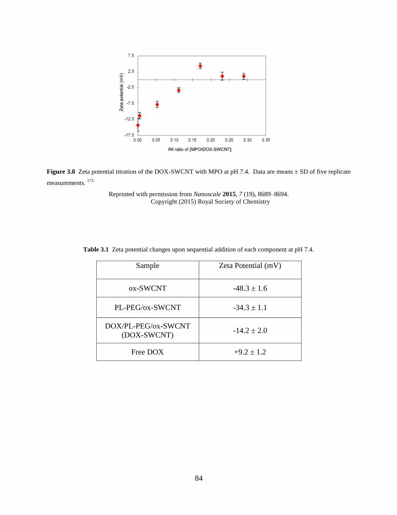
84
Figure 3.8 Zeta potential titration of the DOX-SWCNT with MPO at pH 7.4. Data are means ± SD of five replicate
measurements. 173
Reprinted with permission from Nanoscale 2015, 7 (19), 8689–8694.
Copyright (2015) Royal Society of Chemistry
Table 3.1 Zeta potential changes upon sequential addition of each component at pH 7.4.
Sample Zeta Potential (mV)
ox-SWCNT -48.3 ± 1.6
PL-PEG/ox-SWCNT -34.3 ± 1.1
DOX/PL-PEG/ox-SWCNT
(DOX-SWCNT) -14.2 ± 2.0
Free DOX +9.2 ± 1.2
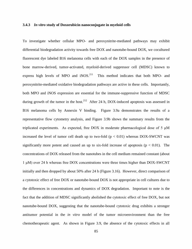
85
3.4.3 In vitro study of Doxorubicin nanoconjugate in myeloid cells
To investigate whether cellular MPO- and peroxynitrite-mediated pathways may exhibit
differential biodegradation activity towards free DOX and nanotube-bound DOX, we cocultured
fluorescent dye labeled B16 melanoma cells with each of the DOX samples in the presence of
bone marrow-derived, tumor-activated, myeloid-derived suppressor cell (MDSC) known to
express high levels of MPO and iNOS.211
This method indicates that both MPO- and
peroxynitrite-mediated oxidative biodegradation pathways are active in these cells. Importantly,
both MPO and iNOS expression are essential for the immune-suppressive function of MDSC
during growth of the tumor in the host.212
After 24 h, DOX-induced apoptosis was assessed in
B16 melanoma cells by Annexin V binding. Figure 3.9a demonstrates the results of a
representative flow cytometry analysis, and Figure 3.9b shows the summary results from the
triplicated experiments. As expected, free DOX in moderate pharmacological dose of 5 μM
increased the level of tumor cell death up to two-fold (p < 0.01) whereas DOX-SWCNT was
significantly more potent and caused an up to six-fold increase of apoptosis (p < 0.01). The
concentrations of DOX released from the nanotubes in the cell medium remained constant (about
1 μM) over 24 h whereas free DOX concentrations were three times higher than DOX-SWCNT
initially and then dropped by about 50% after 24 h (Figure 3.16). However, direct comparison of
a cytotoxic effect of free DOX or nanotube-bound DOX is not appropriate in cell cultures due to
the differences in concentrations and dynamics of DOX degradation. Important to note is the
fact that the addition of MDSC significantly abolished the cytotoxic effect of free DOX, but not
nanotube-bound DOX, suggesting that the nanotube-bound cytotoxic drug exhibits a stronger
antitumor potential in the in vitro model of the tumor microenvironment than the free
chemotherapeutic agent. As shown in Figure 3.9, the absence of the cytotoxic effects in all
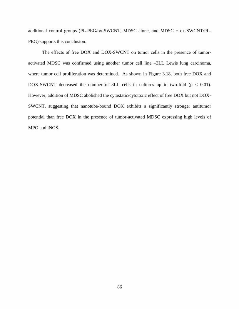
86
additional control groups (PL-PEG/ox-SWCNT, MDSC alone, and MDSC + ox-SWCNT/PL-
PEG) supports this conclusion.
The effects of free DOX and DOX-SWCNT on tumor cells in the presence of tumor-
activated MDSC was confirmed using another tumor cell line –3LL Lewis lung carcinoma,
where tumor cell proliferation was determined. As shown in Figure 3.18, both free DOX and
DOX-SWCNT decreased the number of 3LL cells in cultures up to two-fold (p < 0.01).
However, addition of MDSC abolished the cytostatic/cytotoxic effect of free DOX but not DOX-
SWCNT, suggesting that nanotube-bound DOX exhibits a significantly stronger antitumor
potential than free DOX in the presence of tumor-activated MDSC expressing high levels of
MPO and iNOS.
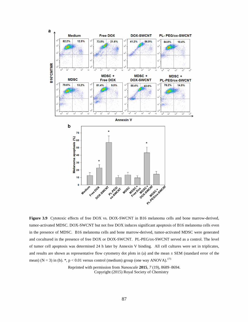
87
Figure 3.9 Cytotoxic effects of free DOX vs. DOX-SWCNT in B16 melanoma cells and bone marrow-derived,
tumor-activated MDSC. DOX-SWCNT but not free DOX induces significant apoptosis of B16 melanoma cells even
in the presence of MDSC. B16 melanoma cells and bone marrow-derived, tumor-activated MDSC were generated
and cocultured in the presence of free DOX or DOX-SWCNT. PL-PEG/ox-SWCNT served as a control. The level
of tumor cell apoptosis was determined 24 h later by Annexin V binding. All cell cultures were set in triplicates,
and results are shown as representative flow cytometry dot plots in (a) and the mean ± SEM (standard error of the
mean) (N = 3) in (b). *, p < 0.01 versus control (medium) group (one way ANOVA).173
Reprinted with permission from Nanoscale 2015, 7 (19), 8689–8694.
Copyright (2015) Royal Society of Chemistry
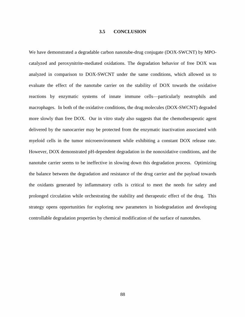
88
3.5 CONCLUSION
We have demonstrated a degradable carbon nanotube-drug conjugate (DOX-SWCNT) by MPO-
catalyzed and peroxynitrite-mediated oxidations. The degradation behavior of free DOX was
analyzed in comparison to DOX-SWCNT under the same conditions, which allowed us to
evaluate the effect of the nanotube carrier on the stability of DOX towards the oxidative
reactions by enzymatic systems of innate immune cells—particularly neutrophils and
macrophages. In both of the oxidative conditions, the drug molecules (DOX-SWCNT) degraded
more slowly than free DOX. Our in vitro study also suggests that the chemotherapeutic agent
delivered by the nanocarrier may be protected from the enzymatic inactivation associated with
myeloid cells in the tumor microenvironment while exhibiting a constant DOX release rate.
However, DOX demonstrated pH-dependent degradation in the nonoxidative conditions, and the
nanotube carrier seems to be ineffective in slowing down this degradation process. Optimizing
the balance between the degradation and resistance of the drug carrier and the payload towards
the oxidants generated by inflammatory cells is critical to meet the needs for safety and
prolonged circulation while orchestrating the stability and therapeutic effect of the drug. This
strategy opens opportunities for exploring new parameters in biodegradation and developing
controllable degradation properties by chemical modification of the surface of nanotubes.
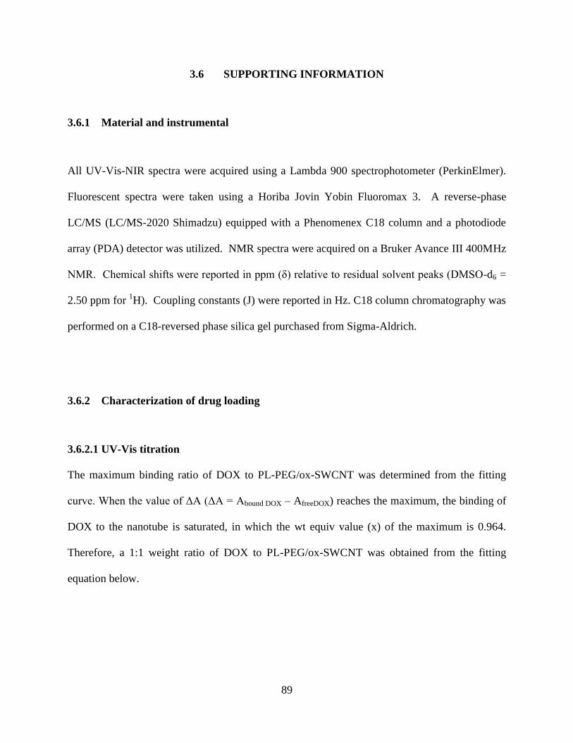
89
3.6 SUPPORTING INFORMATION
3.6.1 Material and instrumental
All UV-Vis-NIR spectra were acquired using a Lambda 900 spectrophotometer (PerkinElmer).
Fluorescent spectra were taken using a Horiba Jovin Yobin Fluoromax 3. A reverse-phase
LC/MS (LC/MS-2020 Shimadzu) equipped with a Phenomenex C18 column and a photodiode
array (PDA) detector was utilized. NMR spectra were acquired on a Bruker Avance III 400MHz
NMR. Chemical shifts were reported in ppm (δ) relative to residual solvent peaks (DMSO-d6 =
2.50 ppm for 1H). Coupling constants (J) were reported in Hz. C18 column chromatography was
performed on a C18-reversed phase silica gel purchased from Sigma-Aldrich.
3.6.2 Characterization of drug loading
3.6.2.1 UV-Vis titration
The maximum binding ratio of DOX to PL-PEG/ox-SWCNT was determined from the fitting
curve. When the value of ΔA (ΔA = Abound DOX – AfreeDOX) reaches the maximum, the binding of
DOX to the nanotube is saturated, in which the wt equiv value (x) of the maximum is 0.964.
Therefore, a 1:1 weight ratio of DOX to PL-PEG/ox-SWCNT was obtained from the fitting
equation below.
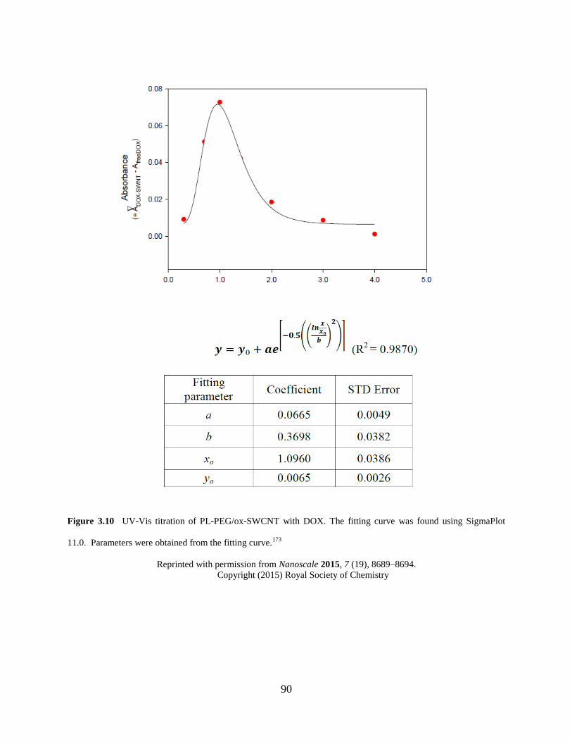
90
Figure 3.10 UV-Vis titration of PL-PEG/ox-SWCNT with DOX. The fitting curve was found using SigmaPlot
11.0. Parameters were obtained from the fitting curve.173
Reprinted with permission from Nanoscale 2015, 7 (19), 8689–8694.
Copyright (2015) Royal Society of Chemistry
91
3.6.2.2 Zeta potential titration
A solution of PL-PEG/ox-SWCNT in nanopure water (0.2 mg/mL) was prepared, and a 3 mL of
the aliquot was transferred to a 20 mL scintillation vial. Then the varying amount of DOX
solution in water (1.3 mg/mL) was added to the vial. After 30 min of sonication, the zeta
potential of the solution mixture was measured with a dynamic light scattering detector. Using a
graphical linear fitting curve near the saturation point at y-axis (0 mV), the corresponding wt
equiv value was estimated. Approximately at 1.12 equiv, the zeta potential remains constant.
Here, a 1.1:1 binding ratio of DOX to PL-PEG/ox-SWCNT was found. The graphical linear fit
was obtained by OriginPro 8.5.
Figure 3.11 Zeta potential titration of PL-PEG/ox-SWCNT with DOX.173
Reprinted with permission from Nanoscale 2015, 7 (19), 8689–8694.
Copyright (2015) Royal Society of Chemistry
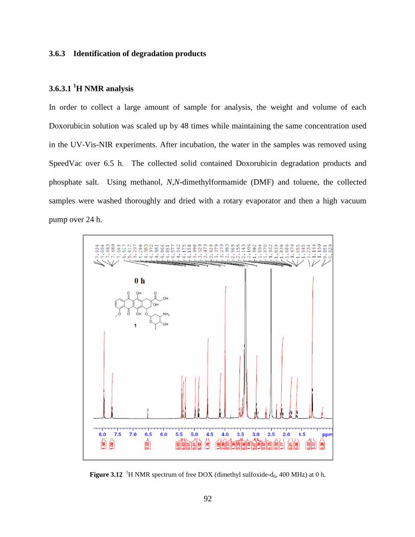
92
3.6.3 Identification of degradation products
3.6.3.1 1H NMR analysis
In order to collect a large amount of sample for analysis, the weight and volume of each
Doxorubicin solution was scaled up by 48 times while maintaining the same concentration used
in the UV-Vis-NIR experiments. After incubation, the water in the samples was removed using
SpeedVac over 6.5 h. The collected solid contained Doxorubicin degradation products and
phosphate salt. Using methanol, N,N-dimethylformamide (DMF) and toluene, the collected
samples were washed thoroughly and dried with a rotary evaporator and then a high vacuum
pump over 24 h.
Figure 3.12 1H NMR spectrum of free DOX (dimethyl sulfoxide-d6, 400 MHz) at 0 h.
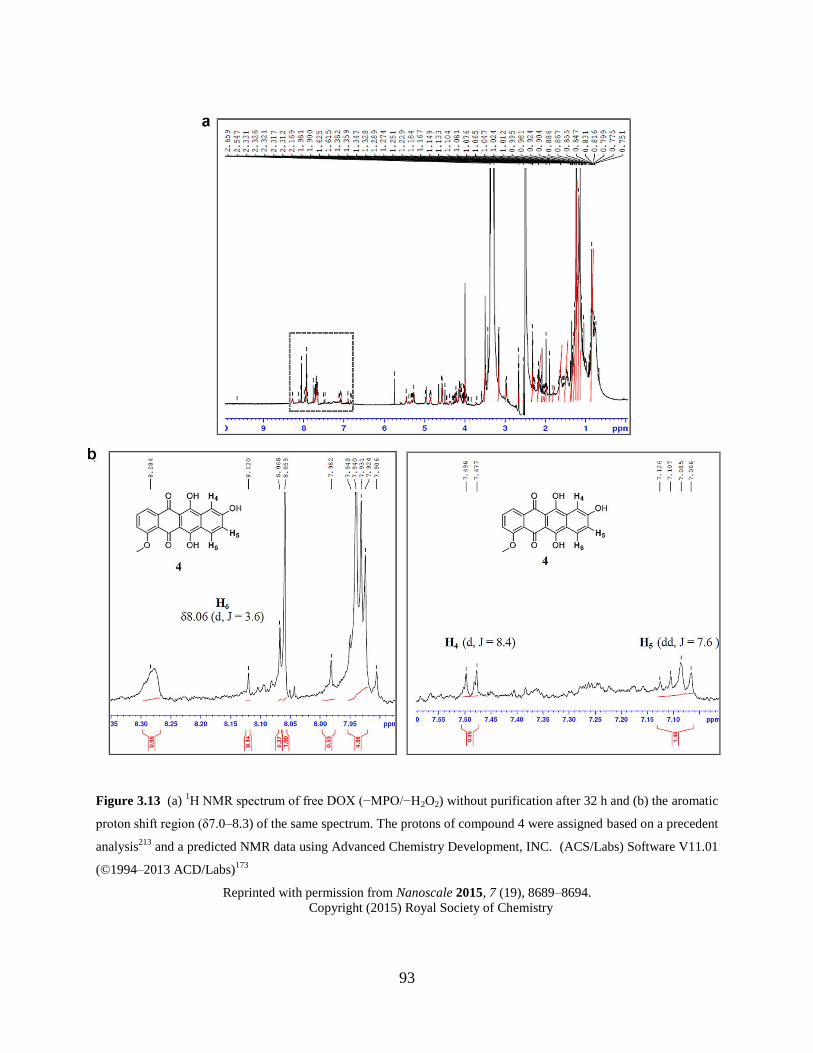
93
Figure 3.13 (a) 1H NMR spectrum of free DOX (−MPO/−H2O2) without purification after 32 h and (b) the aromatic
proton shift region (δ7.0–8.3) of the same spectrum. The protons of compound 4 were assigned based on a precedent
analysis213
and a predicted NMR data using Advanced Chemistry Development, INC. (ACS/Labs) Software V11.01
(©1994–2013 ACD/Labs)173
Reprinted with permission from Nanoscale 2015, 7 (19), 8689–8694.
Copyright (2015) Royal Society of Chemistry
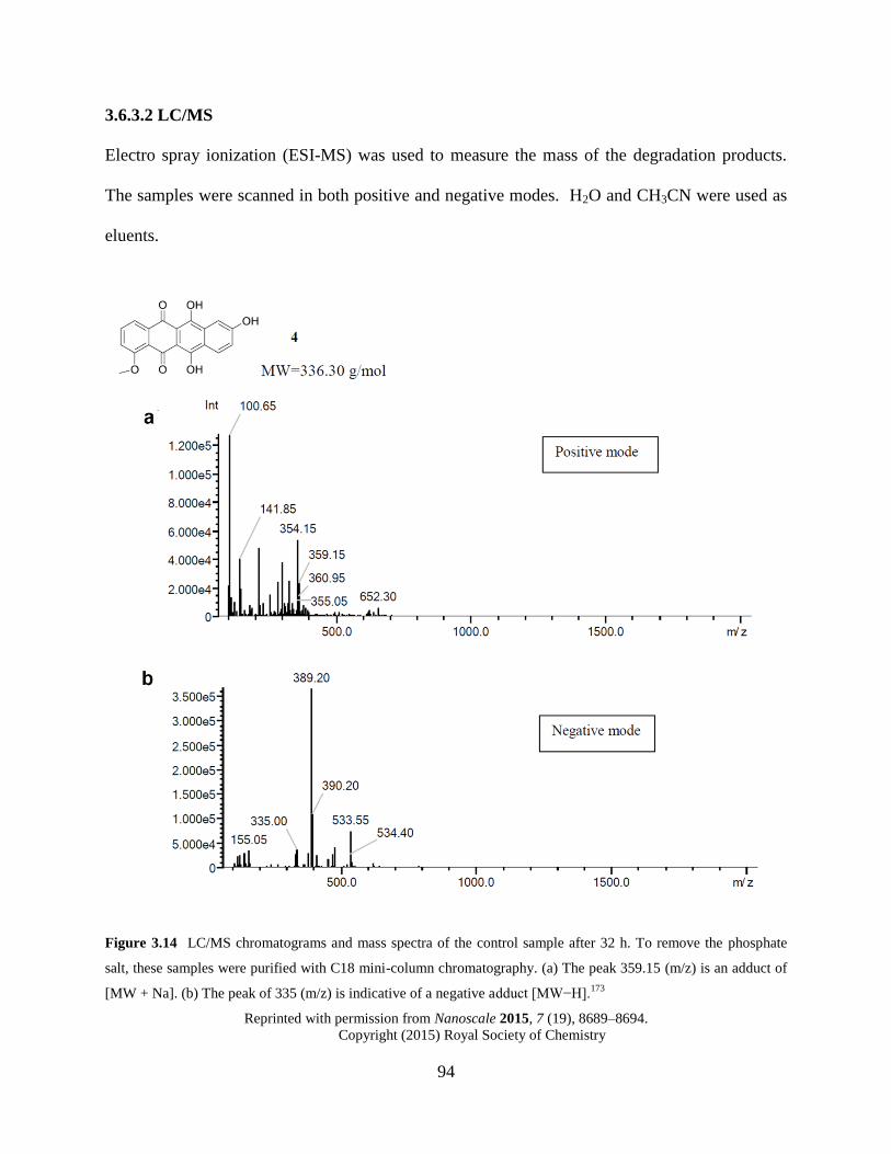
94
3.6.3.2 LC/MS
Electro spray ionization (ESI-MS) was used to measure the mass of the degradation products.
The samples were scanned in both positive and negative modes. H2O and CH3CN were used as
eluents.
Figure 3.14 LC/MS chromatograms and mass spectra of the control sample after 32 h. To remove the phosphate
salt, these samples were purified with C18 mini-column chromatography. (a) The peak 359.15 (m/z) is an adduct of
[MW + Na]. (b) The peak of 335 (m/z) is indicative of a negative adduct [MW−H].173
Reprinted with permission from Nanoscale 2015, 7 (19), 8689–8694.
Copyright (2015) Royal Society of Chemistry
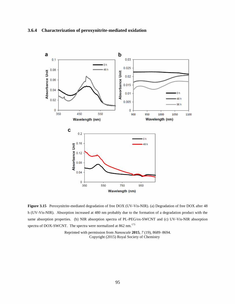
95
3.6.4 Characterization of peroxynitrite-mediated oxidation
Figure 3.15 Peroxynitrite-mediated degradation of free DOX (UV-Vis-NIR). (a) Degradation of free DOX after 48
h (UV-Vis-NIR). Absorption increased at 480 nm probably due to the formation of a degradation product with the
same absorption properties. (b) NIR absorption spectra of PL-PEG/ox-SWCNT and (c) UV-Vis-NIR absorption
spectra of DOX-SWCNT. The spectra were normalized at 862 nm.173
Reprinted with permission from Nanoscale 2015, 7 (19), 8689–8694.
Copyright (2015) Royal Society of Chemistry
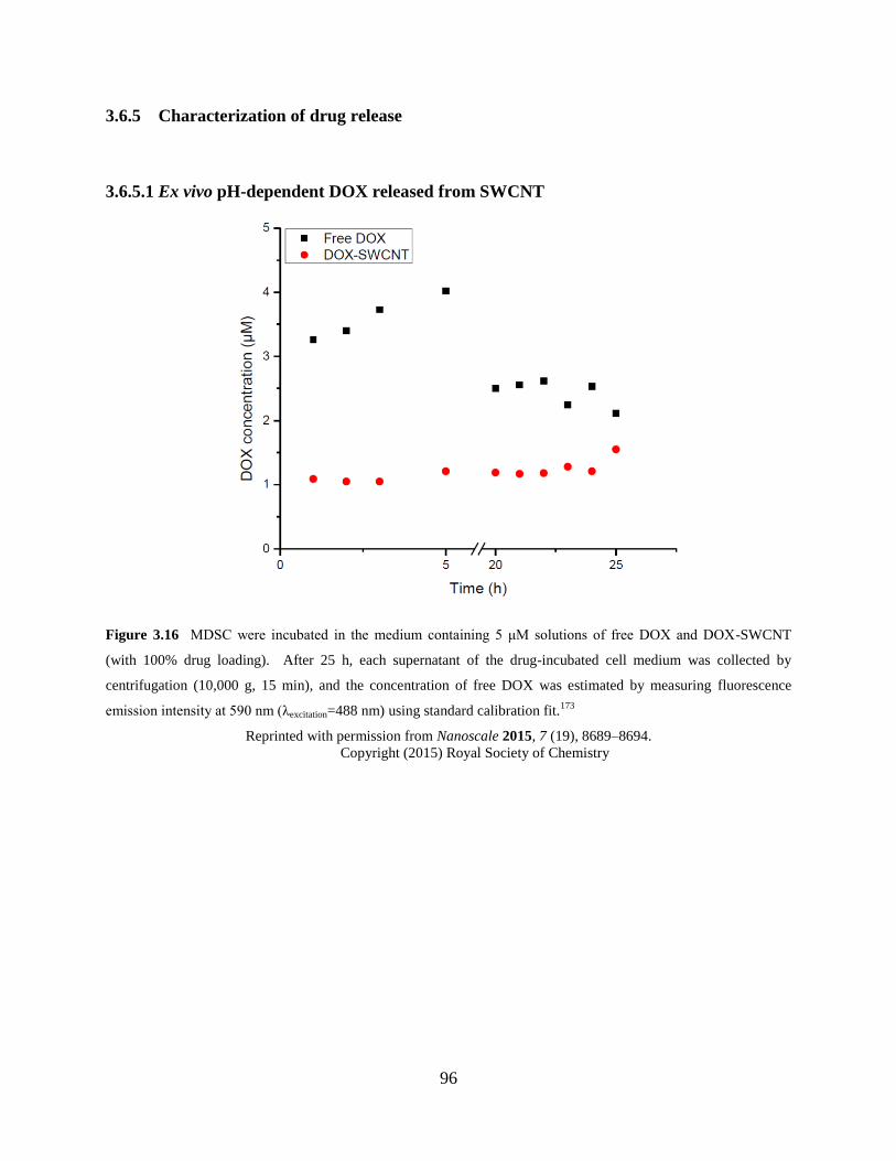
96
3.6.5 Characterization of drug release
3.6.5.1 Ex vivo pH-dependent DOX released from SWCNT
Figure 3.16 MDSC were incubated in the medium containing 5 μM solutions of free DOX and DOX-SWCNT
(with 100% drug loading). After 25 h, each supernatant of the drug-incubated cell medium was collected by
centrifugation (10,000 g, 15 min), and the concentration of free DOX was estimated by measuring fluorescence
emission intensity at 590 nm (λexcitation=488 nm) using standard calibration fit.173
Reprinted with permission from Nanoscale 2015, 7 (19), 8689–8694.
Copyright (2015) Royal Society of Chemistry
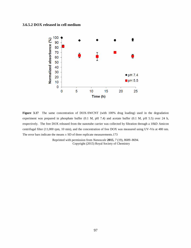
97
3.6.5.2 DOX released in cell medium
Figure 3.17 The same concentration of DOX-SWCNT (with 100% drug loading) used in the degradation
experiment was prepared in phosphate buffer (0.1 M, pH 7.4) and acetate buffer (0.1 M, pH 5.5) over 24 h,
respectively. The free DOX released from the nanotube carrier was collected by filtration through a 10kD Amicon
centrifugal filter (11,000 rpm, 10 min), and the concentration of free DOX was measured using UV-Vis at 480 nm.
The error bars indicate the means ± SD of three replicate measurements.173
Reprinted with permission from Nanoscale 2015, 7 (19), 8689–8694.
Copyright (2015) Royal Society of Chemistry
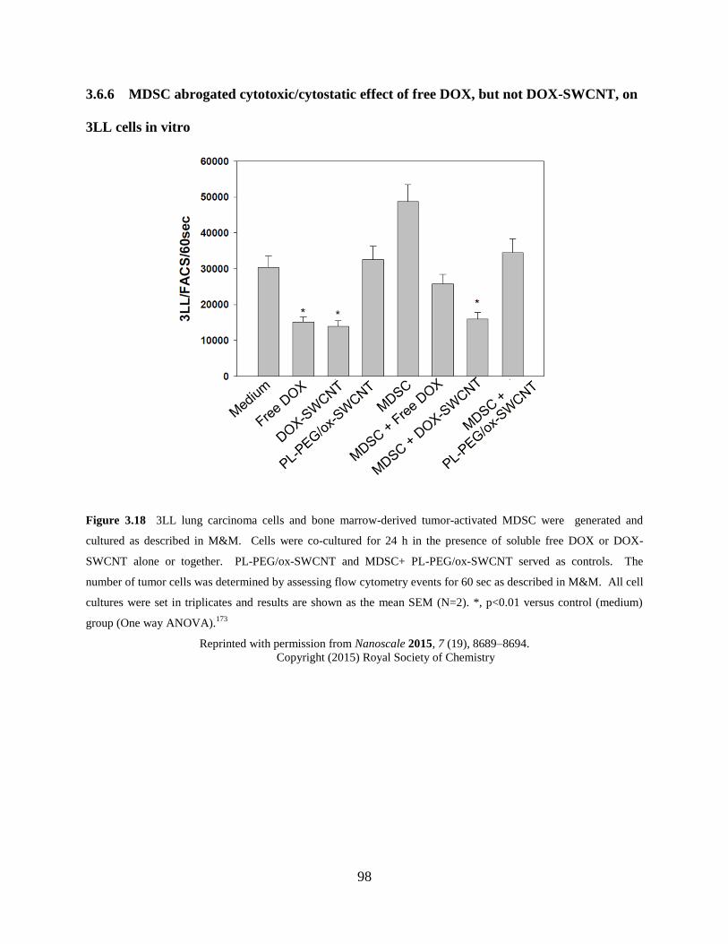
98
3.6.6 MDSC abrogated cytotoxic/cytostatic effect of free DOX, but not DOX-SWCNT, on
3LL cells in vitro
Figure 3.18 3LL lung carcinoma cells and bone marrow-derived tumor-activated MDSC were generated and
cultured as described in M&M. Cells were co-cultured for 24 h in the presence of soluble free DOX or DOX-
SWCNT alone or together. PL-PEG/ox-SWCNT and MDSC+ PL-PEG/ox-SWCNT served as controls. The
number of tumor cells was determined by assessing flow cytometry events for 60 sec as described in M&M. All cell
cultures were set in triplicates and results are shown as the mean SEM (N=2). *, p<0.01 versus control (medium)
group (One way ANOVA).173
Reprinted with permission from Nanoscale 2015, 7 (19), 8689–8694.
Copyright (2015) Royal Society of Chemistry
99
4.0 SYNTHESIS AND CHARACTERIZATION OF TWO-DIMENSIONAL
SUPRAMOLECULAR POLYMERS
4.1 CHAPTER PREFACE
This study is described in a manuscript entitled Polybenzobisimidazole-Derived Two-
Dimensional Supramolecular Polymer, which was submitted for publication. Additionally, a
short application study of a surface catalyst for Fenton-like oxidation is described. W. Seo
thanks Damodaran Krishnan Achary for 13
C CP MAS solid-state NMR analysis and Keith A.
Werling and Professor Daniel S. Lambrecht Department of Chemistry at the University of
Pittsburgh for computational modeling. W. Seo synthesized and characterized the
supramolecular polymer. Philip M. Fournier performed SEM analysis; James A. Gaugler and
Keith L. Carpenter assisted in preparation of monomers.
100
4.2 INTRODUCTION
Chapter 4 describes the design and synthesis of a novel two-dimensional polymer (2DP).
Envisioning realization of a 2D semiconducting and chemical sensing material for field effect
transistor (FET) devices, we designed a novel covalent organic framework COF-Salophen
consisting of multiple salophen macrocycles (Figure 4.1). This covalent organic framework
(COF) can be synthesized by condensation of aromatic monomers bearing aldehyde and amine
functional groups,214,215
which provides an imine linker connecting salophen units and pores of
two different sizes. The salophen ligands can serve as a sensing moiety for the detection of
Co(II) ions,216
and the extended π–conjugated system imparts planarity and rigidity, thereby
providing semiconducting properties to the polymer.217
The high surface-to-volume ratio of 2D
COFs allows for facile electron transfer due to the excellent surface contact with FET chips.218
However, an initial effort for direct condensation of 1 and commercially available 1,2,4,5-
benzenetetramine tetrahydrochloride, the precursor of 2, in the presence of N,N-
diisopropylethylamine failed to provide COF-Salophen. We also attempted to neutralize 1,2,4,5-
benzenetetramine tetrahydrochloride before polymerization, but found that spontaneous air-
oxidation of an unstable 2 provided 3 under atmospheric conditions. Despite the conversion into
the diamine group of 3, we have utilized it as a monomer for polycondensation with 1 to
investigate whether the product forms a conjugated linear polymer that may possess electrical
properties. Interestingly, we have found that a novel supramolecular polymer (SP-PBBI) by self-
assembly of linear polybenzobisimidazole (PBBI) chains in a one-step reaction. SP-PBBI
features a regular arrangement of rigid rod-like PBBI chains stabilized by intramolecular
hydrogen bonding within a planar sheet. The size of SP-PBBI crystal growth can be tuned by
employing a nonisothermal condition in the precipitation polymerization process.
101
Liquid-phase exfoliation of as-synthesized, bulk SP-PBBI that is insoluble in most
organic solvents provides thin layers of the polymer 2DSP-PBBI (thickness of <20 nm). The
surface morphology of the polymer is analyzed with liquid-exfoliated samples, based on which
the supramolecular polymerization of PBBI building units is elucidated. Titration with cobalt
chloride (CoCl2) using UV-Vis spectroscopy confirms the presence of bidentate NO pendant
ligands coordinating with Co(II) and Cu(II). The Cu(II)/2DSP-PBBI complex is further utilized
for catalyzing oxidation of highly ordered pyrolytic graphite (HOPG) by a Fenton-like process.
The resulting defect formation is analyzed with Raman spectroscopy data and AFM micrographs
of the oxidized HOPG surface.
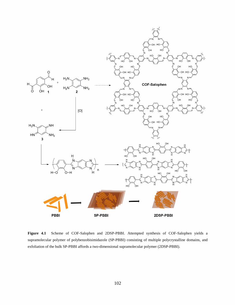
102
Figure 4.1 Scheme of COF-Salophen and 2DSP-PBBI. Attempted synthesis of COF-Salophen yields a
supramolecular polymer of polybenzobisimidazole (SP-PBBI) consisting of multiple polycrystalline domains, and
exfoliation of the bulk SP-PBBI affords a two-dimensional supramolecular polymer (2DSP-PBBI).
103
4.2.1 Two-dimensional polymers
The importance of two-dimensional graphene-like materials such as 2D polymers (2DPs),
hexagonal boron nitride, organic/inorganic hybrids and hierarchically ordered various van der
Waals heterostructures is rapidly recognized.219-224
The development of 2D materials will allow
for exploration of novel properties that can greatly enhance the performance of materials and
nanodevices.220
However, the synthesis of 2D materials, whether by top-down or bottom-up
approaches, requires high precision at the atomic scale to achieve fine-tuned properties.219,225
2D
materials processing has often encountered a great deal of difficulty translating benchtop
research into scalable production.226
A large number of 2DPs have been studied as a new class of emerging materials for the
last half a decade.219,227,229
The current and future applications of 2DPs include FETs,
supercapacitors,228
photovoltaic cells,215,229
surface catalysts,230
and colorimetric sensing231
.
2DPs can be constructed by connecting building units covalently (e.g., COFs) or noncovalently
(e.g., SPs).58,219,227,232
Supramolecular polymers are formed based on geometric preorganization
generated by noncovalent intermolecular forces existing in the building unit, such as hydrogen
bonding, π–π stacking, and metal–ligand complexation.233-236
Supramolecular systems provide
convenient synthetic routes to build complex macromolecular frameworks.233
The intrinsically
dynamic nature is suitable for recyclable, degradable, stimulus-responsive, sensing, and self-
healing materials.235
However, reversible noncovalent interactions in supramolecular systems
could inadvertently be disrupted depending on the external environment and the entire polymer
can disintegrate.237
Metallosupramolecular polymers (MSP) complement properties most
organic macromolecules lack intrinsically. A diverse range of metal ions offers great
applications to optoelectronics, sensing, nanopatterning, and macromolecular catalysts.235-236
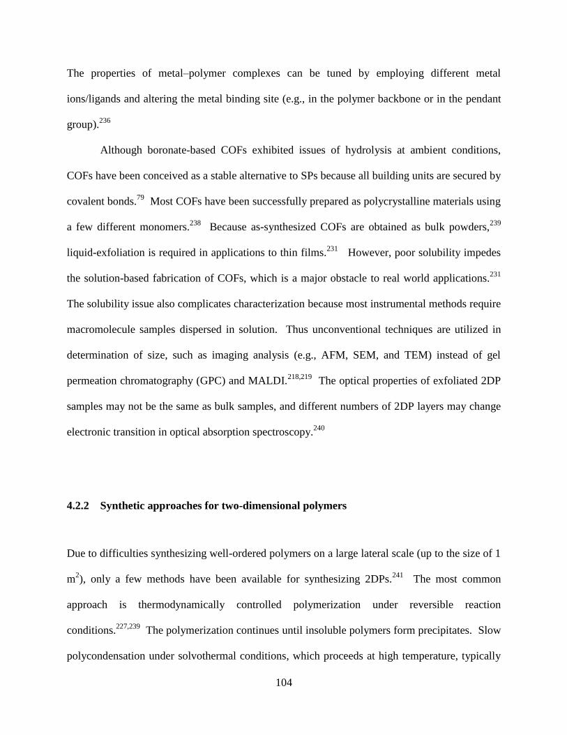
104
The properties of metal–polymer complexes can be tuned by employing different metal
ions/ligands and altering the metal binding site (e.g., in the polymer backbone or in the pendant
group).236
Although boronate-based COFs exhibited issues of hydrolysis at ambient conditions,
COFs have been conceived as a stable alternative to SPs because all building units are secured by
covalent bonds.79
Most COFs have been successfully prepared as polycrystalline materials using
a few different monomers.238
Because as-synthesized COFs are obtained as bulk powders,239
liquid-exfoliation is required in applications to thin films.231
However, poor solubility impedes
the solution-based fabrication of COFs, which is a major obstacle to real world applications.231
The solubility issue also complicates characterization because most instrumental methods require
macromolecule samples dispersed in solution. Thus unconventional techniques are utilized in
determination of size, such as imaging analysis (e.g., AFM, SEM, and TEM) instead of gel
permeation chromatography (GPC) and MALDI.218,219
The optical properties of exfoliated 2DP
samples may not be the same as bulk samples, and different numbers of 2DP layers may change
electronic transition in optical absorption spectroscopy.240
4.2.2 Synthetic approaches for two-dimensional polymers
Due to difficulties synthesizing well-ordered polymers on a large lateral scale (up to the size of 1
m2), only a few methods have been available for synthesizing 2DPs.
241 The most common
approach is thermodynamically controlled polymerization under reversible reaction
conditions.227,239
The polymerization continues until insoluble polymers form precipitates. Slow
polycondensation under solvothermal conditions, which proceeds at high temperature, typically
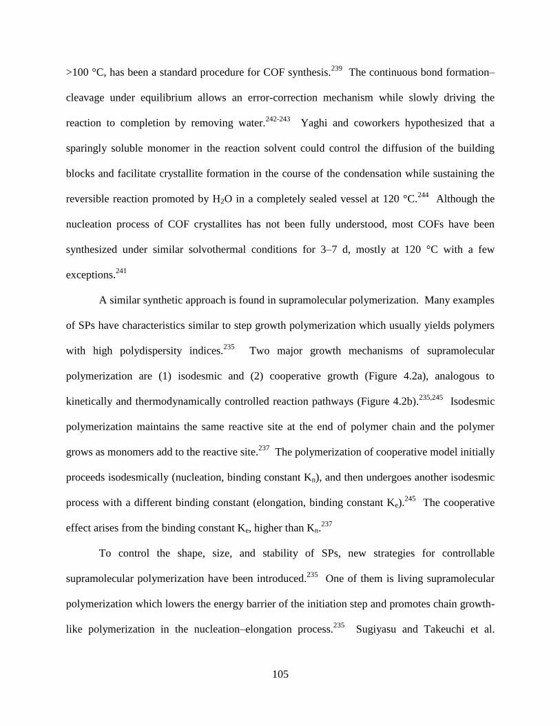
105
>100 °C, has been a standard procedure for COF synthesis.239
The continuous bond formation–
cleavage under equilibrium allows an error-correction mechanism while slowly driving the
reaction to completion by removing water.242-243
Yaghi and coworkers hypothesized that a
sparingly soluble monomer in the reaction solvent could control the diffusion of the building
blocks and facilitate crystallite formation in the course of the condensation while sustaining the
reversible reaction promoted by H2O in a completely sealed vessel at 120 °C.244
Although the
nucleation process of COF crystallites has not been fully understood, most COFs have been
synthesized under similar solvothermal conditions for 3–7 d, mostly at 120 °C with a few
exceptions.241
A similar synthetic approach is found in supramolecular polymerization. Many examples
of SPs have characteristics similar to step growth polymerization which usually yields polymers
with high polydispersity indices.235
Two major growth mechanisms of supramolecular
polymerization are (1) isodesmic and (2) cooperative growth (Figure 4.2a), analogous to
kinetically and thermodynamically controlled reaction pathways (Figure 4.2b).235,245
Isodesmic
polymerization maintains the same reactive site at the end of polymer chain and the polymer
grows as monomers add to the reactive site.237
The polymerization of cooperative model initially
proceeds isodesmically (nucleation, binding constant Kn), and then undergoes another isodesmic
process with a different binding constant (elongation, binding constant Ke).245
The cooperative
effect arises from the binding constant Ke, higher than Kn.237
To control the shape, size, and stability of SPs, new strategies for controllable
supramolecular polymerization have been introduced.235
One of them is living supramolecular
polymerization which lowers the energy barrier of the initiation step and promotes chain growth-
like polymerization in the nucleation–elongation process.235
Sugiyasu and Takeuchi et al.
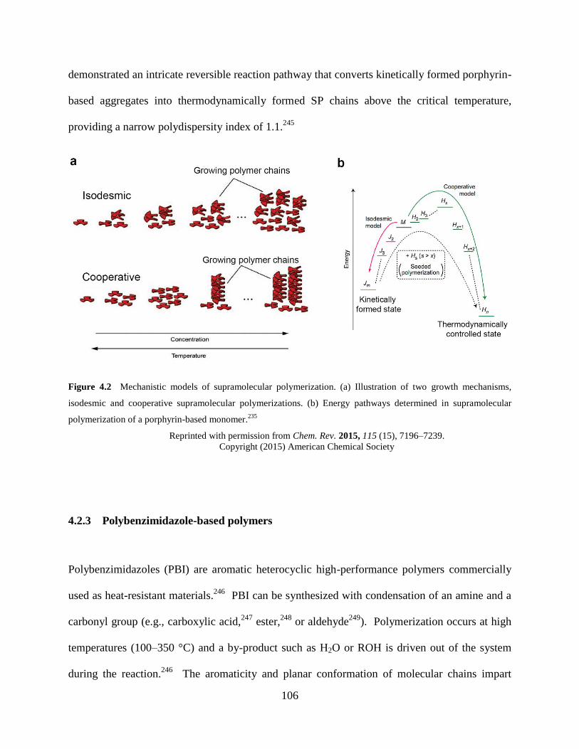
106
demonstrated an intricate reversible reaction pathway that converts kinetically formed porphyrin-
based aggregates into thermodynamically formed SP chains above the critical temperature,
providing a narrow polydispersity index of 1.1.245
Figure 4.2 Mechanistic models of supramolecular polymerization. (a) Illustration of two growth mechanisms,
isodesmic and cooperative supramolecular polymerizations. (b) Energy pathways determined in supramolecular
polymerization of a porphyrin-based monomer.235
Reprinted with permission from Chem. Rev. 2015, 115 (15), 7196–7239.
Copyright (2015) American Chemical Society
4.2.3 Polybenzimidazole-based polymers
Polybenzimidazoles (PBI) are aromatic heterocyclic high-performance polymers commercially
used as heat-resistant materials.246
PBI can be synthesized with condensation of an amine and a
carbonyl group (e.g., carboxylic acid,247
ester,248
or aldehyde249
). Polymerization occurs at high
temperatures (100–350 °C) and a by-product such as H2O or ROH is driven out of the system
during the reaction.246
The aromaticity and planar conformation of molecular chains impart
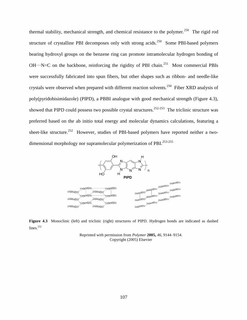
107
thermal stability, mechanical strength, and chemical resistance to the polymer.250
The rigid rod
structure of crystalline PBI decomposes only with strong acids.250
Some PBI-based polymers
bearing hydroxyl groups on the benzene ring can promote intramolecular hydrogen bonding of
OH···N=C on the backbone, reinforcing the rigidity of PBI chain.251
Most commercial PBIs
were successfully fabricated into spun fibers, but other shapes such as ribbon- and needle-like
crystals were observed when prepared with different reaction solvents.250
Fiber XRD analysis of
poly(pyridobisimidazole) (PIPD), a PBBI analogue with good mechanical strength (Figure 4.3),
showed that PIPD could possess two possible crystal structures.252-253
The triclinic structure was
preferred based on the ab initio total energy and molecular dynamics calculations, featuring a
sheet-like structure.252
However, studies of PBI-based polymers have reported neither a two-
dimensional morphology nor supramolecular polymerization of PBI.253-255
Figure 4.3 Monoclinic (left) and triclinic (right) structures of PIPD. Hydrogen bonds are indicated as dashed
lines.252
Reprinted with permission from Polymer 2005, 46, 9144–9154.
Copyright (2005) Elsevier
108
4.3 EXPERIMENTAL
4.3.1 Synthesis of SP-PBBI and 2DSP-PBBI
Monomers 1 and 3 were synthesized as described in Ch. 4.6 Supporting Information. A solution
of 1 (6.0 mg, 0.04 mmol) and 3 (3.3 mg, 0.02 mmol) in N,N-dimethylformamide (1 mL) was
prepared in a 25 mL round bottom flask. The solution of the monomers was degassed by two
freeze–pump–thaw cycles and was sealed with a septum and PTFE tape. After sonication for 5
min, the reaction mixture was kept at 95 °C (for 2 d) in an oil bath without stirring at 100 °C for
1 d. After raising the temperature to 145°C, the reaction was left undisturbed for 3 d. After total
6 d, the reaction flask was cooled to room temperature for 2 h, and the crude polymer was
washed with dichloromethane (4 × 15 mL) and methanol (4 × 15 mL) over a Millipore filter and
a 200 nm fluorophore filter membrane. After drying in vacuo for 48 h over 100 °C, 2DSP–PBBI
was obtained as a dark brown solid (89 %). 13
C CP MAS solid-state NMR (15 kHz) δ ppm,
198.6, 150.0, 147.0, 138.2, 129.9, 121.3, 119.0, 116.5, 99.0. IR (KBr, ATR) 3327, 1641, 1440,
1394, 1302, 1152, 839 cm−1
.
Exfoliation was performed in a 100 mL round bottom flask containing dry SP-PBBI (2.0
mg) and anhydrous DMF (12 mL) with gentle stirring for 24 h at 60 °C.
4.3.2 Instrumentation
Fourier transform infrared spectroscopy (FTIR) was performed using an IR-Prestige
spectrophotometer (Shimadzu Scientific) outfitted with an EasiDiff accessory (Pike
109
Technologies). Solid samples were ground with KBr to prepare a homogenous mixture. 13
C CP
MAS spectroscopy was performed on a Bruker Avance spectrometer (500 MHz). Powder X-ray
diffraction (PXRD) was recorded on a Bruker X8 Prospector Ultra equipped with a Bruker Smart
Apex CCD diffractometer and a copper micro-focus X-ray source employing Cu Kα radiation at
40 kV, 40 mA. A ground sample was loaded in a capillary tube (D: 1 mm) for analysis. The size
and the morphology of materials were analyzed with transmission electron microscope (FEI-
Morgani, 80 keV). TEM samples were prepared by drop-casting 3.5 µL of a sample onto a lacey
carbon films/400 mesh copper grid and dried under ambient conditions over 24 h. An Asylum
MFP-3D atomic force microscope (AFM) was utilized with high resolution probes (Hi’Res-
C14/Cr-Au) purchased from MikroMasch. AFM samples were prepared by deposition of 10 µL
of an exfoliated solution onto freshly cleaved mica. The sample was spin coated and then
allowed to dry under ambient conditions over 24 h. UV-Vis-NIR spectra were acquired using a
Lambda 900 spectrophotometer (PerkinElmer). Scanning Electron Microscopy (SEM) was
performed with FEI XL-30 (20 keV). The computational molecular structure optimizations were
performed at the B3LYP/6-31g(d) level with Q-Chem software packages.256-257
A fine
integration grid and stricter self-consistent-field and integral thresholds were utilized.
4.3.3 Titration of metal–polybenzobisimidazole complexation
A supernatant containing relatively well-suspended polymer flakes was collected from the
exfoliated solution of 2DSP-PBBI for the spectroscopy measurements. A 5.3 mM CoCl2
solution was prepared in DMF, and 5 µL was delivered to an exfoliated polymer solution (600
µL) for each titration at ambient conditions. The optical change of 2DSP-PBBI solution was
110
measured using UV-Vis absorption spectroscopy immediately after each addition of CoCl2. The
exfoliated 2DSP-PBBI solution was also titrated with CuSO4 using the same protocol. A Cu(II)
solution (2.0 mM) was prepared with CuSO4∙5H2O and DMF for serial addition of 30 μL to an
exfoliated 2DSP-PBBI solution (625 μL). An estimated weight of the polymer in 625 μL was
about 36 μg.
4.3.4 Fabrication of porous graphene by Fenton-like oxidation
HOPG flakes (0.5 mm × 0.5 mm) were mechanically cleaved with a razor. The surface was
mechanically exfoliated with cellophane tape to smoothen the HOPG surface. Each flake was
cleaned with CH2Cl2, acetone, DI water, and acetone sequentially. The flake was dried over a
hot plate at 50 °C for 24 h. An exfoliated 2DSP–PBBI solution (625 uL) in DMF was gently
mixed with Cu(II) (2 mM, 390 μL) at room temperature based on the titration experiment data.
The cleaned HOPG flakes were placed on a glass slide and the aliquot of Cu(II)/2DSP–PBBI
solution was drop-cast on the HOPG flake (20 μL). After 6 h, the solution was applied to the
other side of HOPG flakes and the samples were allowed to dry for 12 h at 50 °C.
A polymer-deposited HOPG flake was placed in a 1 dram vial containing 0.2 mL of
acetonitrile or a mixture of acetonitrile: pH 5.0 buffer (1:1, v/v). A 20 μL of H2O2 solution 30%
(w/w) was added, followed by gentle shaking for 30 sec, and the capped vial was placed in a
sand bath at 65 °C. The same amount of H2O2 solution was replenished at every 6 h (20 μL per
addition). For UV-activated photo-Fenton reactions, a quartz cuvette (3.5 mm × 12.5 mm × 45
mm) was used to store the HOPG sample in the biphasic solution at room temperature and was

111
held ∼20 cm from a UV lamp (Blak-Ray B100AP, 100-W long wave UV, which produces
fluorescence with a ballasted bulb).
112
4.4 RESULTS AND DISCUSSION
4.4.1 Characterization of SP-PBBI
In an attempt to perform imine condensation under neutral conditions, 1,2,4,5-benzenetetramine
tetrahydrochloride was treated under a basic condition in air prior to polymerization. However,
rapid conversion of 2 to 3 led to polycondensation of 2,3-dihydroxybenzene-1,4-dicarbaldehyde
1 and 3,6-diimino-1,4-cyclohexadiene-1,4-diamine 3 in N,N-dimethylformamide (DMF) at 95–
145 °C. An aprotic polar solvent DMF was employed to completely solubilize both 1 and 3,
thereby initiating precipitate polymerization in a homogenous solution. DMF may also have
facilitated π–π stacking due to the enhanced solvophobic effect and self-assembled
macromolecular structures.258-259
Condensation of 1 and 3 allowed formation of two imine bonds
and subsequent cyclization to a benzobisimidazole (PBBI) moiety. To confirm the formation of
benzobisimidazole from the diamino diene 3, a model compound 4 was prepared with
salicylaldehyde and 3 under the same nonisothermal condition (Figure 4.10 and 4.12c–e). The
reaction afforded a brown powder of as-synthesized SP-PBBI in 89% yield, exhibiting
insolubility in water and most common organic solvents at room temperature. The sufficiently
long reaction time (total 6 d) was crucial to high polymer conversions whereas reactions
performed less than 3 d formed the precipitated product in much lower conversions.
The FTIR spectrum (Figure 4.4a) of SP-PBBI confirms the formation of an imine (C=N)
stretching at 1641 cm−1
in the polymer sample while peaks characteristic to the monomers such
as the aldehyde C–H stretching (2866 and 2769 cm−1
) of 1 and primary amine N–H stretching
(3444 and 3417 cm−1
) of 3 are clearly absent (Figure 4.11b–c). The relatively high frequency of
an imine stretching can be observed due to the highly rigid conformation arising from the cyclic
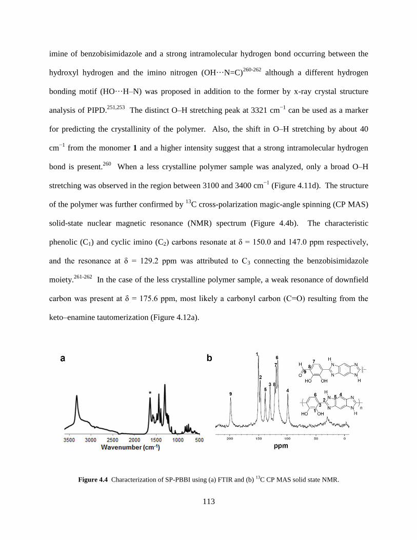
113
imine of benzobisimidazole and a strong intramolecular hydrogen bond occurring between the
hydroxyl hydrogen and the imino nitrogen (OH···N=C)260-262
although a different hydrogen
bonding motif (HO···H–N) was proposed in addition to the former by x-ray crystal structure
analysis of PIPD.251,253
The distinct O–H stretching peak at 3321 cm−1
can be used as a marker
for predicting the crystallinity of the polymer. Also, the shift in O–H stretching by about 40
cm−1
from the monomer 1 and a higher intensity suggest that a strong intramolecular hydrogen
bond is present.260
When a less crystalline polymer sample was analyzed, only a broad O–H
stretching was observed in the region between 3100 and 3400 cm−1
(Figure 4.11d). The structure
of the polymer was further confirmed by 13
C cross-polarization magic-angle spinning (CP MAS)
solid-state nuclear magnetic resonance (NMR) spectrum (Figure 4.4b). The characteristic
phenolic (C1) and cyclic imino (C2) carbons resonate at δ = 150.0 and 147.0 ppm respectively,
and the resonance at δ = 129.2 ppm was attributed to C3 connecting the benzobisimidazole
moiety.261-262
In the case of the less crystalline polymer sample, a weak resonance of downfield
carbon was present at δ = 175.6 ppm, most likely a carbonyl carbon (C=O) resulting from the
keto–enamine tautomerization (Figure 4.12a).
Figure 4.4 Characterization of SP-PBBI using (a) FTIR and (b) 13
C CP MAS solid state NMR.
114
To support the evidence of a periodic structure with well-defined crystalline parameters,
powder X-ray diffraction (PXRD) was implemented. As shown in the experimental PXRD
spectrum (Figure 4.5a), d spacing values corresponding to the well-defined peaks were found
(16.67, 8.43, 6.33, 5.86, and 3.31 Å), based on which a two-dimensional unit cell model (a and b
axes) was proposed (Figure 4.5b). To construct a periodic alignment of the PBBI chains, we
referred to the structural analyses of PIPD that is very similar to PBBI except for the position of
one hydroxyl group and the pyridine moiety.251-253
Based on the bond lengths and unit cell
(either monoclinic or triclinic) data of PIPD provided by two different groups, we indexed a =
16.67 Å and b = 6.63 Å for SP–PBBI parameters (Figure 4.5b). These lattice parameters are
very different from those of the COF-Salophen estimated at the B3LYP/6-31g(d) level (Figure
4.5c). We reason that the interlayer spacing (c axis) is 3.31 Å (Figure 4.5d), which is within van
der Waals contact distances arising from the π–π stacking of aromatic rings and comparable to
previously synthesized arene-based polymers.263
Due to limited structural information gleaned
from the powder diffraction data, the analysis of angles between unit cell parameters was not
proposed.253
Thermogravimetric analysis (TGA) showed a weight loss of 10% around 330 °C
and a slow decomposition of 20% up to approximately 400 °C (Figure 4.14).
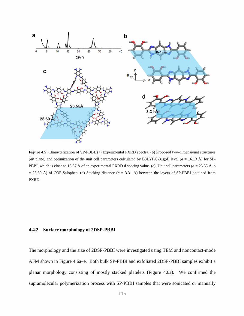
115
Figure 4.5 Characterization of SP-PBBI. (a) Experimental PXRD spectra. (b) Proposed two-dimensional structures
(ab plane) and optimization of the unit cell parameters calculated by B3LYP/6-31g(d) level (a = 16.13 Å) for SP-
PBBI, which is close to 16.67 Å of an experimental PXRD d spacing value. (c) Unit cell parameters (a = 23.55 Å, b
= 25.69 Å) of COF-Salophen. (d) Stacking distance (c = 3.31 Å) between the layers of SP-PBBI obtained from
PXRD.
4.4.2 Surface morphology of 2DSP-PBBI
The morphology and the size of 2DSP-PBBI were investigated using TEM and noncontact-mode
AFM shown in Figure 4.6a–e. Both bulk SP-PBBI and exfoliated 2DSP-PBBI samples exhibit a
planar morphology consisting of mostly stacked platelets (Figure 4.6a). We confirmed the
supramolecular polymerization process with SP-PBBI samples that were sonicated or manually
116
ground from 5 to 30 min in MeOH. It appears that large planar sheets were disintegrated into
small rods under the mechanical forces, probably due to weakened intermolecular bonds (Figure
4.15a). The planar configuration and rigidity arise from the individual PBBI chain capable of
arranging in a quasi-aromatic six-membered chelate ring induced by intramolecular hydrogen
bonding between the imino nitrogen and the o-hydroxyl group enolimine (OH···N=C).251,254,264
Once linear PBBI backbones are formed and ready for self-preorganization, the secondary amine
(NH), the imine (N=C), and 1,2-dihydroxyphenyl (OH) groups of PBBI provide intermolecular
hydrogen bonding motifs for promoting self-assembly and the resulting formation of SP. Each
2DSP-PBBI layer consists of multiple crystallites aligned in various orientations, as indicated in
the presence of moiré fringes shown in two different directions (Figure 4.6b).265
A 100 nm-
lateral resolution AFM image also confirms the polycrystalline grain boundaries (Figure 4.6e).
2DSP-PBBI also vertically grows into a 3D bulk (i.e., the formation of SP-PBBI), mainly driven
by π–π stacking existing between the aromatic PBBI backbones. Thus most as-synthesized
samples were multiple stacks strongly held by each 2DSP-PBBI layer and poorly soluble in any
solvents at room temperature. However, we were successfully able to exfoliate bulk SP-PBBI in
DMF at 60 °C. After 2 h-exfoliation, mostly small molecular weight and amorphous-like flakes
were visible under TEM, but larger flakes were slowly delaminated into thin layers (<30 layers)
within 4–6 d (Figure 4.6c and 4.15c). The height distribution of exfoliated layers analyzed by
AFM ranges from 0.4 to 8.6 nm, equivalent to ca. 1–25 layers of the polymer in the sample
(Figure 4.6d and e).
Large polymer sheets up to 0.1–10 μm in lateral dimension were observed under both
TEM (Figure 4.6a and 4.15b) and AFM (Figure 4.16a). Given that cooperative supramolecular
polymerization is based on the two-step mechanism of (1) nucleation and (2) elongation,235
the
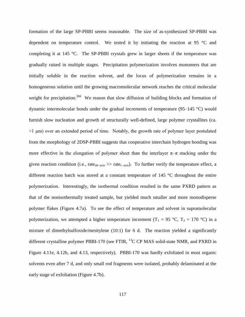
117
formation of the large SP-PBBI seems reasonable. The size of as-synthesized SP-PBBI was
dependent on temperature control. We tested it by initiating the reaction at 95 °C and
completing it at 145 °C. The SP-PBBI crystals grew in larger sheets if the temperature was
gradually raised in multiple stages. Precipitation polymerization involves monomers that are
initially soluble in the reaction solvent, and the locus of polymerization remains in a
homogeneous solution until the growing macromolecular network reaches the critical molecular
weight for precipitation.266
We reason that slow diffusion of building blocks and formation of
dynamic intermolecular bonds under the gradual increments of temperature (95–145 °C) would
furnish slow nucleation and growth of structurally well-defined, large polymer crystallites (ca.
>1 μm) over an extended period of time. Notably, the growth rate of polymer layer postulated
from the morphology of 2DSP-PBBI suggests that cooperative interchain hydrogen bonding was
more effective in the elongation of polymer sheet than the interlayer π–π stacking under the
given reaction condition (i.e., rateab–axis >> ratec–axis). To further verify the temperature effect, a
different reaction batch was stored at a constant temperature of 145 °C throughout the entire
polymerization. Interestingly, the isothermal condition resulted in the same PXRD pattern as
that of the nonisothermally treated sample, but yielded much smaller and more monodisperse
polymer flakes (Figure 4.7a). To see the effect of temperature and solvent in supramolecular
polymerization, we attempted a higher temperature increment (T1 = 95 °C, T2 = 170 °C) in a
mixture of dimethylsulfoxide/mesitylene (10:1) for 6 d. The reaction yielded a significantly
different crystalline polymer PBBI-170 (see FTIR, 13
C CP MAS solid-state NMR, and PXRD in
Figure 4.11e, 4.12b, and 4.13, respectively). PBBI-170 was hardly exfoliated in most organic
solvents even after 7 d, and only small rod fragments were isolated, probably delaminated at the
early stage of exfoliation (Figure 4.7b).
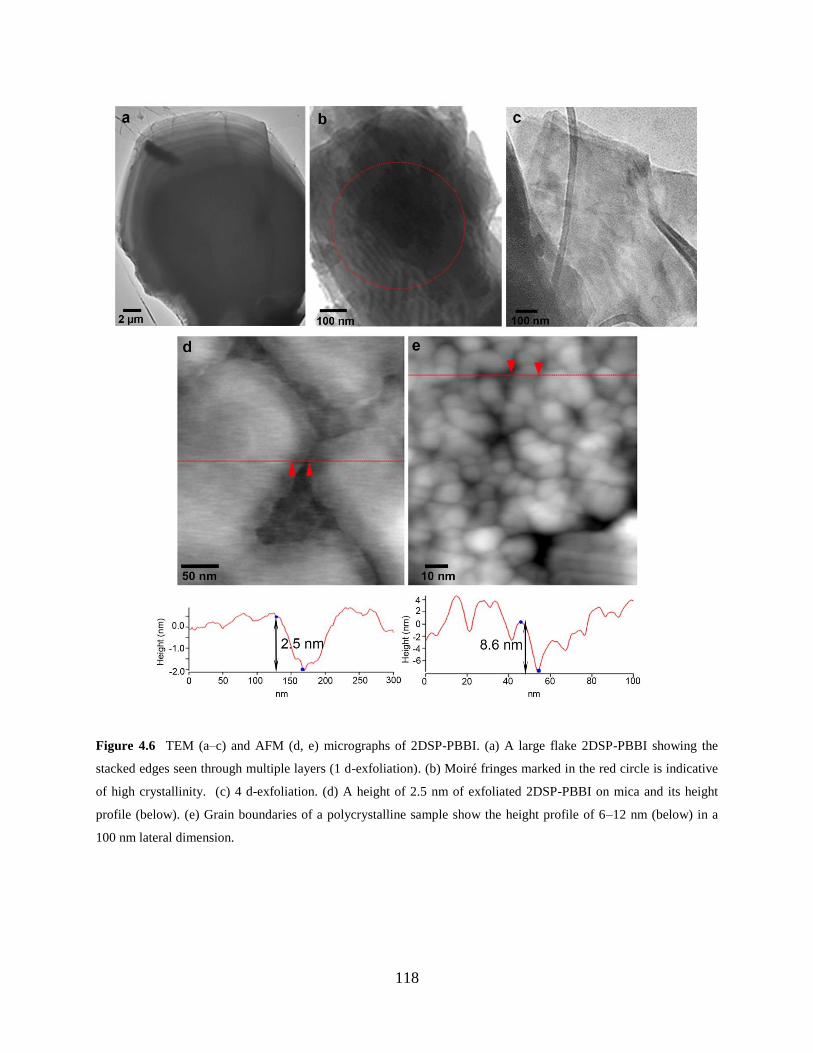
118
Figure 4.6 TEM (a–c) and AFM (d, e) micrographs of 2DSP-PBBI. (a) A large flake 2DSP-PBBI showing the
stacked edges seen through multiple layers (1 d-exfoliation). (b) Moiré fringes marked in the red circle is indicative
of high crystallinity. (c) 4 d-exfoliation. (d) A height of 2.5 nm of exfoliated 2DSP-PBBI on mica and its height
profile (below). (e) Grain boundaries of a polycrystalline sample show the height profile of 6–12 nm (below) in a
100 nm lateral dimension.
119
Figure 4.7 TEM micrographs of (a) PBBI-2 and (b) PBBI-170.
4.4.3 Optical properties of 2DSP-PBBI
We investigated the optical properties of the exfoliated 2DSP-PBBI using UV-Vis absorption
spectroscopy. The absorption spectrum of 2DSP-PBBI exhibits a broad band with a maximum at
381 nm and minor peaks at 274 nm and at 461 nm, clearly different from the absorption bands of
compound 1 and 3 (Figure 4.17). Each PBBI chain possesses bidentate pendant NO ligands,
capable of forming complexation with Co(II), Cu(II), and Zn(II) ions (Figure 4.8a).267-269
To
confirm the complexation of NO–Co(II), titration of exfoliated 2DSP-PBBI in DMF was
performed with cobalt(II) chloride (CoCl2). Upon serial addition of a 5.2 mM CoCl2 aliquot to
the polymer solution, the absorbance at 381 nm progressively decreases, indicative of the metal–
ligand complexation (Figure 4.8b). The titration spectra also show a successively increasing
absorption band at 609 and 674 nm with the addition of Co(II). The inset of Figure 4.8b shows
120
the saturation point of NO–Co(II) complexation, based on which a 1.2:1 binding stoichiometry
of Co(II) to the NO ligand was estimated. The CoCl2 solution in DMF showed absorption bands
at 609 and 674 nm, typical of pseudotetrahedral complexes of Co(II),270
and the wavelength of
these bands did not change during the titration of 2DSP-PBBI. This result indicates that ligand
exchange between the NO and Cl−/DMF occurred while maintaining the pseudotetrahedral
geometry in the CoCl2 solution (Figure 4.8c).271
After titration of 2DSP-PBBI with Co(II), the
polymer sample was analyzed by SEM imaging, showing that the planar sheet-like shape
remained intact.
To test the realization of conjugated 2DSP-PBBI as a semiconducting material, the
energy band gap was estimated from emission/excitation spectroscopy (Figure 4.18a).272
From
the excitation (at 382 nm) and emission (at 512 nm) spectra, an energy band gap of 1.08 eV was
calculated, indicating that exfoliated 2DSP-PBBI is semiconducting. Having designed a
semiconducting sensing material, we performed drop-casting of an exfoliated 2DSP-PBBI
sample on a chip, but no significant conductance was observed in FET–IV curves (Figure 4.18b).
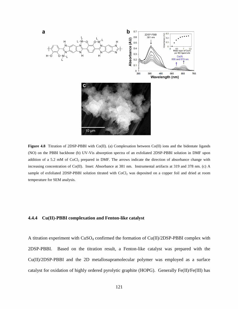
121
Figure 4.8 Titration of 2DSP-PBBI with Co(II). (a) Complexation between Co(II) ions and the bidentate ligands
(NO) on the PBBI backbone (b) UV-Vis absorption spectra of an exfoliated 2DSP-PBBI solution in DMF upon
addition of a 5.2 mM of CoCl2 prepared in DMF. The arrows indicate the direction of absorbance change with
increasing concentration of Co(II). Inset: Absorbance at 381 nm. Instrumental artifacts at 319 and 378 nm. (c) A
sample of exfoliated 2DSP-PBBI solution titrated with CoCl2 was deposited on a copper foil and dried at room
temperature for SEM analysis.
4.4.4 Cu(II)-PBBI complexation and Fenton-like catalyst
A titration experiment with CuSO4 confirmed the formation of Cu(II)/2DSP-PBBI complex with
2DSP-PBBI. Based on the titration result, a Fenton-like catalyst was prepared with the
Cu(II)/2DSP-PBBI and the 2D metallosupramolecular polymer was employed as a surface
catalyst for oxidation of highly ordered pyrolytic graphite (HOPG). Generally Fe(II)/Fe(III) has
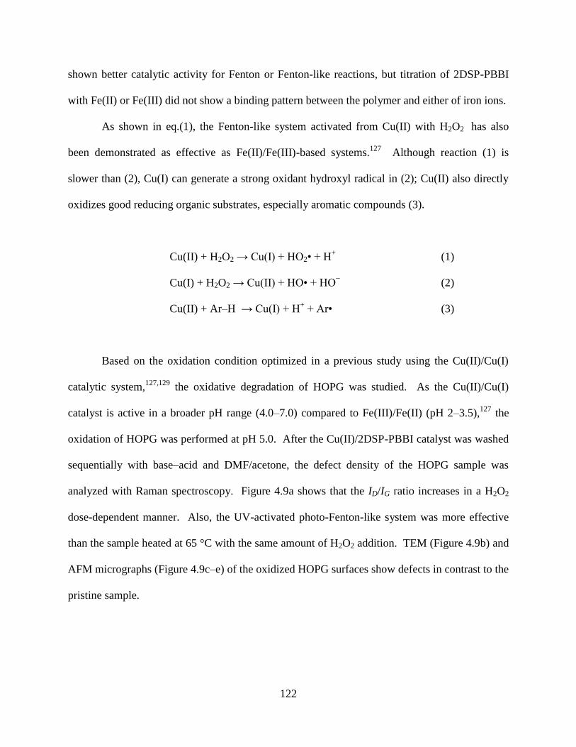
122
shown better catalytic activity for Fenton or Fenton-like reactions, but titration of 2DSP-PBBI
with Fe(II) or Fe(III) did not show a binding pattern between the polymer and either of iron ions.
As shown in eq.(1), the Fenton-like system activated from Cu(II) with H2O2 has also
been demonstrated as effective as Fe(II)/Fe(III)-based systems.127
Although reaction (1) is
slower than (2), Cu(I) can generate a strong oxidant hydroxyl radical in (2); Cu(II) also directly
oxidizes good reducing organic substrates, especially aromatic compounds (3).
Cu(II) + H2O2 → Cu(I) + HO2• + H+
(1)
Cu(I) + H2O2 → Cu(II) + HO• + HO−
(2)
Cu(II) + Ar–H → Cu(I) + H+ + Ar• (3)
Based on the oxidation condition optimized in a previous study using the Cu(II)/Cu(I)
catalytic system,127,129
the oxidative degradation of HOPG was studied. As the Cu(II)/Cu(I)
catalyst is active in a broader pH range (4.0–7.0) compared to Fe(III)/Fe(II) (pH 2–3.5),127
the
oxidation of HOPG was performed at pH 5.0. After the Cu(II)/2DSP-PBBI catalyst was washed
sequentially with base–acid and DMF/acetone, the defect density of the HOPG sample was
analyzed with Raman spectroscopy. Figure 4.9a shows that the ID/IG ratio increases in a H2O2
dose-dependent manner. Also, the UV-activated photo-Fenton-like system was more effective
than the sample heated at 65 °C with the same amount of H2O2 addition. TEM (Figure 4.9b) and
AFM micrographs (Figure 4.9c–e) of the oxidized HOPG surfaces show defects in contrast to the
pristine sample.
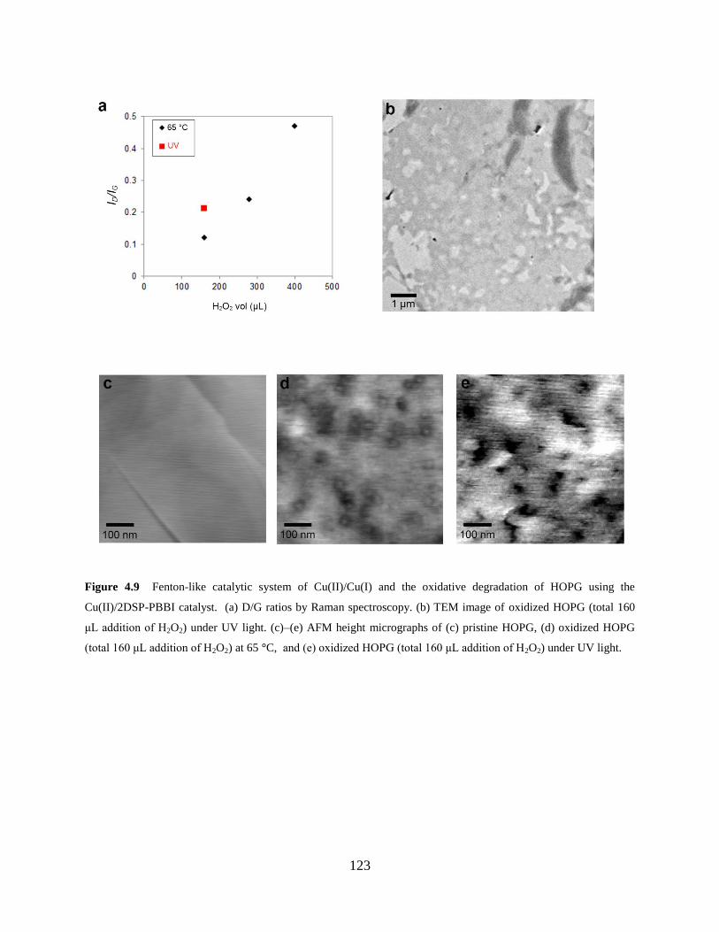
123
Figure 4.9 Fenton-like catalytic system of Cu(II)/Cu(I) and the oxidative degradation of HOPG using the
Cu(II)/2DSP-PBBI catalyst. (a) D/G ratios by Raman spectroscopy. (b) TEM image of oxidized HOPG (total 160
μL addition of H2O2) under UV light. (c)–(e) AFM height micrographs of (c) pristine HOPG, (d) oxidized HOPG
(total 160 μL addition of H2O2) at 65 °C, and (e) oxidized HOPG (total 160 μL addition of H2O2) under UV light.
124
4.5 CONCLUSION
We were able to develop a strategy for the one-step synthesis of 2DSP-PBBI by precipitation
polymerization. The slow crystallite growth and precipitation under controlled conditions
allowed formation of well-defined 2DSP-PBBI, and the lateral dimension of <10 μm was
achieved by the nonisothermally controlled reaction temperature. PBBI building blocks were
laterally grown into large self-assembled planar 2DSP sheets primarily by interchain hydrogen
bonding. Also, π–π stacking facilitated formation of an orderly stacked architecture from
individual 2DSP sheets. Liquid-exfoliation of the as-synthesized SP-PBBI polymer provided
planar sheets of 2DSP-PBBI up to submicrometer lateral widths and nanometer heights. In
addition, the complexation with Cu(II) was confirmed by the Cu(II)/2DSP-PBBI catalyst for the
Fenton-like oxidation of HOPG. Despite some concerns regarding the susceptibility to
mechanical forces, we anticipate that simple dropcast of exfoliated 2DSP-PBBI will provide
convenient means for building various 2D heterostructures enabling cost-effective, scalable
production.
125
4.6 SUPPORTING INFORMATION
4.6.1 General and instrumentation
Graphene oxide was purchased from Graphene Supermarket. All other chemicals were obtained
from Sigma Aldrich and used without further purification. All reaction solvents were anhydrous
reagent graded. Silica gel for column chromatography was obtained from Selecto Scientific. Thin
layer chromatography was performed on Merck TLC plates pre-coated with silica gel 60 F254.
Visualization of the developed plates was performed by fluorescence quenching or by ninhydrin
and phosphomolybdic acid (PMA) stain.
Emission and excitation spectra were recorded on a Horiba Jobin Yvon Nanolog
fluorescence spectrophotometer equipped with a 450 W Xe lamp and double excitation/emission
monochromators. Scanning Electron Microscopy (SEM) and SEM-EDS was performed with
JEOL JSM-6510LV/LGS and an EDS detector equipped with Oxford X-Max large area SDD
detector with INCA microanalysis system, INCAEnergy. Thermogravimetric analysis (TGA)
was conducted on a TGA Q500 thermal analysis system. 1H NMR spectra were recorded on a
Bruker (400 MHz) and were internally referenced to residual protio solvent signals (TMS) at δ
0.00 ppm (1H). 13
C CP MAS spectra were recorded on a Bruker Avance spectrometer (500
MHz). Data were reported as chemical shift (δ ppm) and multiplicity (s = singlet, d = doublet, t
= triplet, q = quartet, qn = quintet, m = multiplet, br = broad), integration, and coupling constant
(J) in Hz. Mass spectra were acquired on Q-Exactive, Thermo Scientific.
126
4.6.2 Synthesis
Synthesis of monomer 2,3-dihydroxybenzene-1,4-dicarbaldehyde (1). Compound 1 was
prepared by the two-step synthesis based on literature procedures.273
To improve the purity, the
crude product was vigorously stirred in 15% sodium thiosulfate solution with addition of
dichloromethane for 6 h. The organic layer was dried over Mg2SO4 and filtered, and then the
solvent was dried in vacuo. Purification through silica gel flash chromatography
(dichloromethane : methanol : acetic acid = 98:1:1) and further recrystallization from 100%
hexanes afforded 83% yield of 1 as a yellow solid. mp 100–101 °C. 1H NMR (400 MHz, CDCl3,
δ) 7.28 (s, 2H), 10.03 (s, 2H), 10.91 (s, 2H). 13
C NMR (125 MHz, CDCl3, δ) 196.3, 150.9, 123.2,
122.2. IR (KBr, ATR) 3371, 3051, 2866, 1654, 1562, 721 cm−1
. HRMS (Multimode-ESI/APCI)
calc’d for C8H6O4 [MH]+ = 167.08335; found 167.08245.
Preparation of monomer 3,6-diimino-1,4-cyclohexadiene-1,4-diamine (3). 1,2,4,5-
Benzenetetramine tetrahydrochloride (1.0 g, 3.5 mmol) and Cs2CO3 (4.0 g, 12.3 mmol)
suspended in MeOH (150 mL) was stirred at room temperature under air for 2 h.274
The
precipitated solid was washed with cold ethanol and then boiling methanol. The crude product
was purified by soxhlet extraction using ethyl acetate as an extraction solvent for 2 d.
Compound 3 was obtained as a dark brown solid (recovery: 63%). 1H NMR (400 MHz, DMSO-
d6, δ) 9.35 (s, 1H), 5.77 (s, 2H), 5.42 (s, 1H). 13
C NMR (125 MHz, DMSO-d6, δ) 158.9, 148.4,
97.5. IR (KBr, ATR) 3444, 3417, 3286, 3244, 1631, 1446, 1346, 1280, 875 cm−1
. HRMS
(Multimode-ESI/APCI) calc’d for C6H8N4 [MH]+=137.0822; found 137.0812.
Synthesis of SP-PBBI-LC. To a solution of compound 1 (6.0 mg, 0.04 mmol) and
1,2,3,4-tetrafluorobenzene (5.4 mg, 0.04 mmol) in N,N-dimethylformamide (1 mL) was added
compound 3 (3.3 mg, 0.02 mmol) in a pyrex tube (OD: 1 mm, H: 18 cm) and degassed by two
127
freeze–pump–thaw cycles. The reaction mixture was stored under the nonisothermal condition
as described in the synthesis of SP-PBBI. The tube was flame-sealed using a propane torch after
two freeze–pump–thaw cycles. Then the reaction was left undisturbed in a convection oven at
95–145 °C for 6 d. 13
C CP/MAS solid-state NMR (15 kHz, δ) 198.6, 175.6, 164.7, 150.0, 147.0,
138.4, 130.1, 119.1, 116.5, 98.8. IR (KBr, ATR). 3325–3118 (br), 2931, 1641, 1558, 1531,
1390, 1300, 1249, 1219, 1153, 1060, 833 cm−1
.
Synthesis of PBBI-170. A solution of 1 (12.0 mg, 0.072 mmol) and 3 (6.65 mg, 0.05
mmol) in a mixture of dimethylsulfoxide (2 mL) and mesitylene (0.2 mL) was prepared in a 25
mL round bottom flask fitted with a Dean–Stark apparatus and a reflux condenser under N2. The
solution was heated as described in the synthesis of PBBI except for 170 °C as the final
temperature. The crude product was washed with dichloromethane and methanol, followed by
drying in vacuo for 72 h over 100 °C heat. PBBI-170 was obtained as a black solid (78 %). 13
C
CP/MAS NMR (10 kHz, δ) 175.9, 150.6, 129.1, 97.8. IR (KBr, ATR) 3560–3360 (br), 2920,
2854, 1693, 1600, 1535, 1435, 1249, 1195, 1161, 1118, 1041, 948 cm−1
.
Synthesis of a small molecule model compound (4). Salicylaldehyde (0.12 g, 1.0
mmol) and 3,6-diimino-1,4-cyclohexadiene-1,4-diamine 3 (34 mg, 0.25 mmol) were suspended
in N,N-dimethylformamide (12 mL). Using the same nonisothermal temperature control
described in the SP-PBBI synthesis, the reaction mixture was heated over 3 d. The crude product
was triturated with hot acetone to give light dull yellow precipitates of compound 4 (65 mg, 0.19
mmol, 77% yield). 1H NMR (400 MHz, DMSO-d6, δ) 13.28 (d, 2H), 13.17 (d, 2H), 8.10 (br,
2H), 8.03 (br, 1H), 7.87 (s,1H), 7.67 (s,1H), 7.41 (t, 2H), 7.04–7.08 (dd, 4H). 13
C NMR (125
MHz, DMSO-d6, δ) 158.6, 132.2, 126.6, 119.6, 117.7, 113.2. HRMS (Multimode-ESI/APCI)
calc’d for C20H15O2N4 [MH]+=343.1190; found 343.1170.
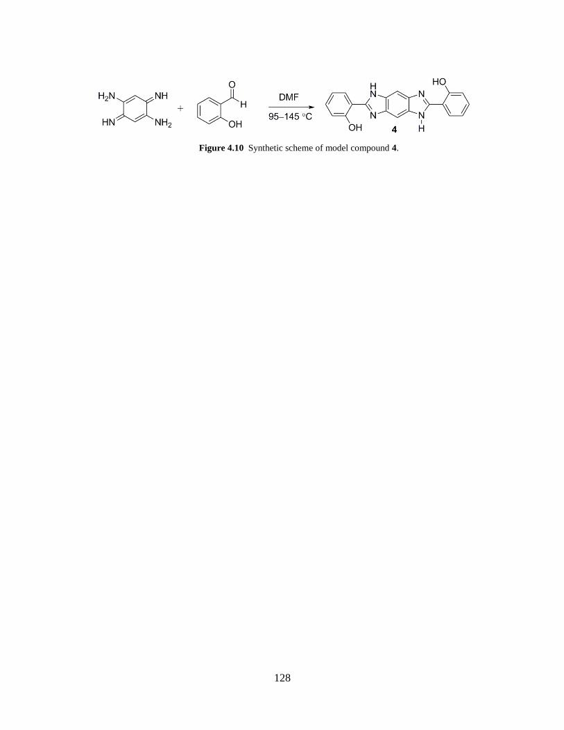
128
Figure 4.10 Synthetic scheme of model compound 4.
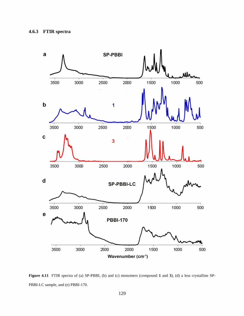
129
4.6.3 FTIR spectra
Figure 4.11 FTIR spectra of (a) SP-PBBI, (b) and (c) monomers (compound 1 and 3), (d) a less crystalline SP-
PBBI-LC sample, and (e) PBBI-170.
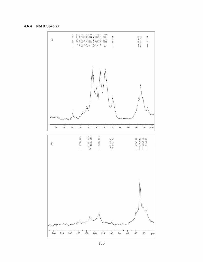
130
4.6.4 NMR Spectra
a
b
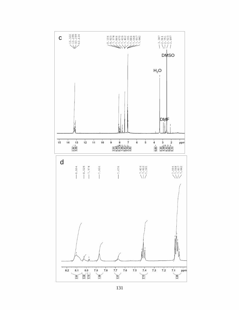
131
d
c
H2O
DMSO
DMF
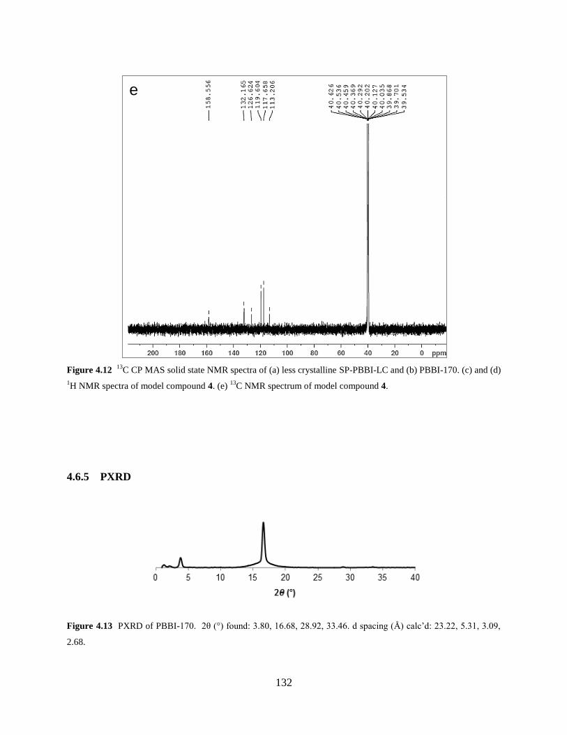
132
Figure 4.12 13
C CP MAS solid state NMR spectra of (a) less crystalline SP-PBBI-LC and (b) PBBI-170. (c) and (d)
1H NMR spectra of model compound 4. (e)
13C NMR spectrum of model compound 4.
4.6.5 PXRD
Figure 4.13 PXRD of PBBI-170. 2θ (°) found: 3.80, 16.68, 28.92, 33.46. d spacing (Å) calc’d: 23.22, 5.31, 3.09,
2.68.
e
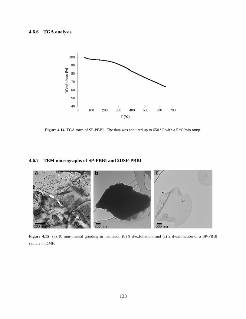
133
4.6.6 TGA analysis
Figure 4.14 TGA trace of SP-PBBI. The data was acquired up to 650 °C with a 5 °C/min ramp.
4.6.7 TEM micrographs of SP-PBBI and 2DSP-PBBI
Figure 4.15 (a) 10 min-manual grinding in methanol, (b) 9 d-exfoliation, and (c) 2 d-exfoliation of a SP-PBBI
sample in DMF.
40
50
60
70
80
90
100
0 100 200 300 400 500 600 700
We
igh
t lo
ss (
%)
T ( C)
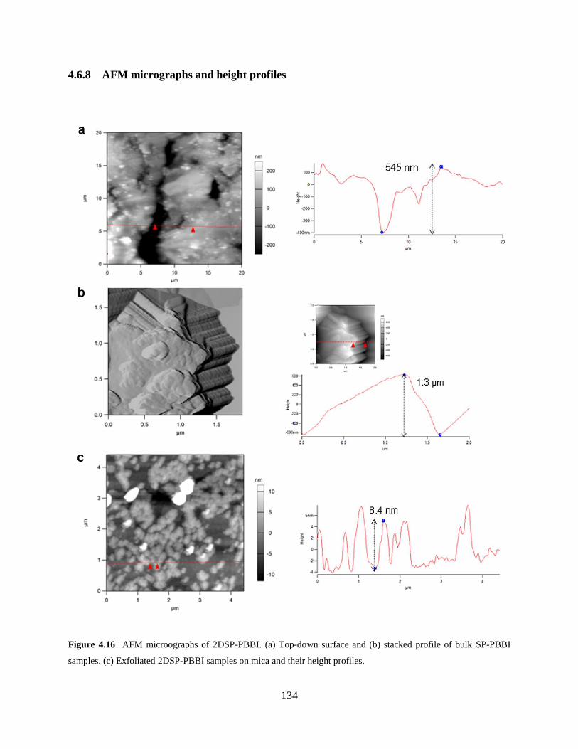
134
4.6.8 AFM micrographs and height profiles
Figure 4.16 AFM microographs of 2DSP-PBBI. (a) Top-down surface and (b) stacked profile of bulk SP-PBBI
samples. (c) Exfoliated 2DSP-PBBI samples on mica and their height profiles.
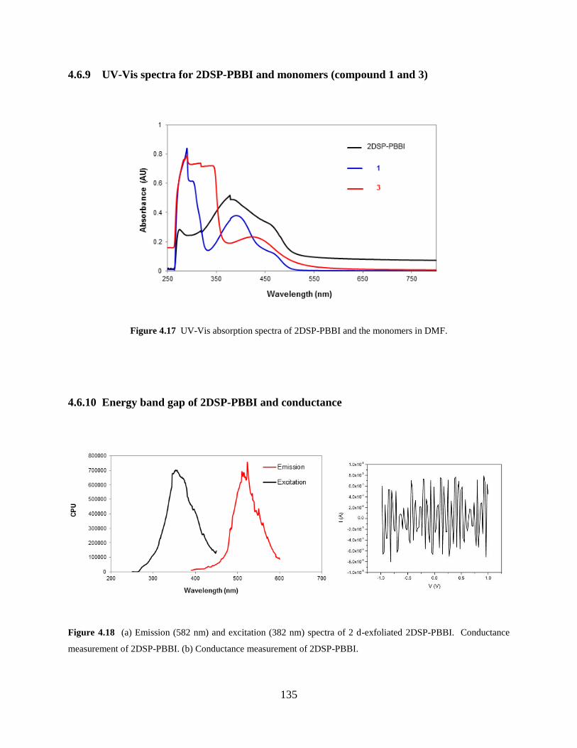
135
4.6.9 UV-Vis spectra for 2DSP-PBBI and monomers (compound 1 and 3)
Figure 4.17 UV-Vis absorption spectra of 2DSP-PBBI and the monomers in DMF.
4.6.10 Energy band gap of 2DSP-PBBI and conductance
Figure 4.18 (a) Emission (582 nm) and excitation (382 nm) spectra of 2 d-exfoliated 2DSP-PBBI. Conductance
measurement of 2DSP-PBBI. (b) Conductance measurement of 2DSP-PBBI.
136
5.0 COVALENT ORGANIC FRAMEWORKS AS SURFACE CATALYSTS FOR
FABRICATING PATTERNED GRAPHENE
5.1 CHAPTER PREFACE
A communication entitled Fabrication of Holey Graphene: Catalytic Oxidation by a
Metalloporphyrin–Based Covalent Organic Framework Immobilized on Highly Ordered
Pyrolytic Graphite was prepared based on this project described in Chapter 5 and submitted to
Chem. Commun.
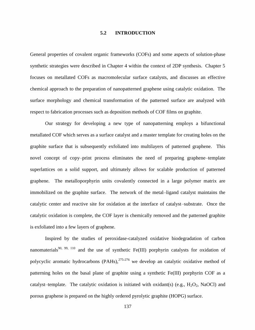
137
5.2 INTRODUCTION
General properties of covalent organic frameworks (COFs) and some aspects of solution-phase
synthetic strategies were described in Chapter 4 within the context of 2DP synthesis. Chapter 5
focuses on metallated COFs as macromolecular surface catalysts, and discusses an effective
chemical approach to the preparation of nanopatterned graphene using catalytic oxidation. The
surface morphology and chemical transformation of the patterned surface are analyzed with
respect to fabrication processes such as deposition methods of COF films on graphite.
Our strategy for developing a new type of nanopatterning employs a bifunctional
metallated COF which serves as a surface catalyst and a master template for creating holes on the
graphite surface that is subsequently exfoliated into multilayers of patterned graphene. This
novel concept of copy–print process eliminates the need of preparing graphene–template
superlattices on a solid support, and ultimately allows for scalable production of patterned
graphene. The metalloporphyrin units covalently connected in a large polymer matrix are
immobilized on the graphite surface. The network of the metal–ligand catalyst maintains the
catalytic center and reactive site for oxidation at the interface of catalyst–substrate. Once the
catalytic oxidation is complete, the COF layer is chemically removed and the patterned graphite
is exfoliated into a few layers of graphene.
Inspired by the studies of peroxidase-catalyzed oxidative biodegradation of carbon
nanomaterials90, 99, 110
and the use of synthetic Fe(III) porphyrin catalysts for oxidation of
polycyclic aromatic hydrocarbons (PAHs),275-276
we develop an catalytic oxidative method of
patterning holes on the basal plane of graphite using a synthetic Fe(III) porphyrin COF as a
catalyst–template. The catalytic oxidation is initiated with oxidant(s) (e.g., H2O2, NaOCl) and
porous graphene is prepared on the highly ordered pyrolytic graphite (HOPG) surface.
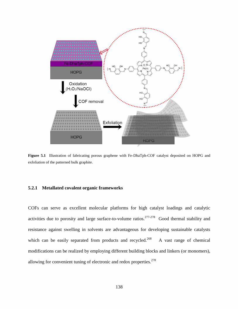
138
Figure 5.1 Illustration of fabricating porous graphene with Fe-DhaTph-COF catalyst deposited on HOPG and
exfoliation of the patterned bulk graphite.
5.2.1 Metallated covalent organic frameworks
COFs can serve as excellent molecular platforms for high catalyst loadings and catalytic
activities due to porosity and large surface-to-volume ratios.277-278
Good thermal stability and
resistance against swelling in solvents are advantageous for developing sustainable catalysts
which can be easily separated from products and recycled.268
A vast range of chemical
modifications can be realized by employing different building blocks and linkers (or monomers),
allowing for convenient tuning of electronic and redox properties.278
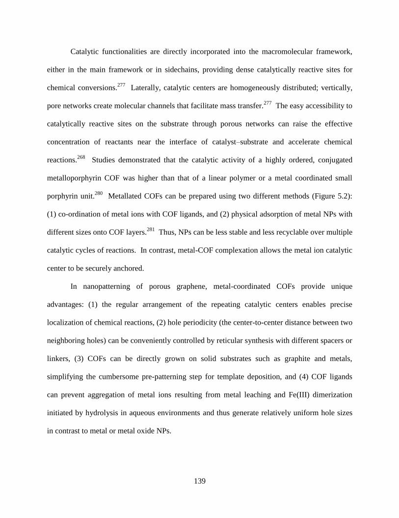
139
Catalytic functionalities are directly incorporated into the macromolecular framework,
either in the main framework or in sidechains, providing dense catalytically reactive sites for
chemical conversions.277
Laterally, catalytic centers are homogeneously distributed; vertically,
pore networks create molecular channels that facilitate mass transfer.277
The easy accessibility to
catalytically reactive sites on the substrate through porous networks can raise the effective
concentration of reactants near the interface of catalyst–substrate and accelerate chemical
reactions.268
Studies demonstrated that the catalytic activity of a highly ordered, conjugated
metalloporphyrin COF was higher than that of a linear polymer or a metal coordinated small
porphyrin unit.280
Metallated COFs can be prepared using two different methods (Figure 5.2):
(1) co-ordination of metal ions with COF ligands, and (2) physical adsorption of metal NPs with
different sizes onto COF layers.281
Thus, NPs can be less stable and less recyclable over multiple
catalytic cycles of reactions. In contrast, metal-COF complexation allows the metal ion catalytic
center to be securely anchored.
In nanopatterning of porous graphene, metal-coordinated COFs provide unique
advantages: (1) the regular arrangement of the repeating catalytic centers enables precise
localization of chemical reactions, (2) hole periodicity (the center-to-center distance between two
neighboring holes) can be conveniently controlled by reticular synthesis with different spacers or
linkers, (3) COFs can be directly grown on solid substrates such as graphite and metals,
simplifying the cumbersome pre-patterning step for template deposition, and (4) COF ligands
can prevent aggregation of metal ions resulting from metal leaching and Fe(III) dimerization
initiated by hydrolysis in aqueous environments and thus generate relatively uniform hole sizes
in contrast to metal or metal oxide NPs.
140
Figure 5.2 Metallated COF catalysts. (a) AuNPs are randomly adsorbed to the COF network.281
(b) Metal ions are
incorporated into the porphyrin COF building unit by forming metal–ligand complexes and regularly positioned.278
Ref. 281. Reprinted with permission from Chem. Commun. 2014, 50 (24), 3169–3172.
Copyright (2014) Royal Society of Chemistry.
Ref. 278. Reprinted with permission from Science 2015, 349 (6253), 1208–1213.
Copyright (2015) The American Association for the Advancement of Science.
5.2.2 On-surface synthesis of covalent organic frameworks
The preparation of uniform COF thin films on solid substrates is important to achieve good
catalytic performance. The deposited COF catalyst should homogenously coat solid substrates in
both lateral and vertical directions, so that well-aligned catalytic functional moieties can
efficiently promote reactions on selective sites. To this end, different bottom-up synthetic
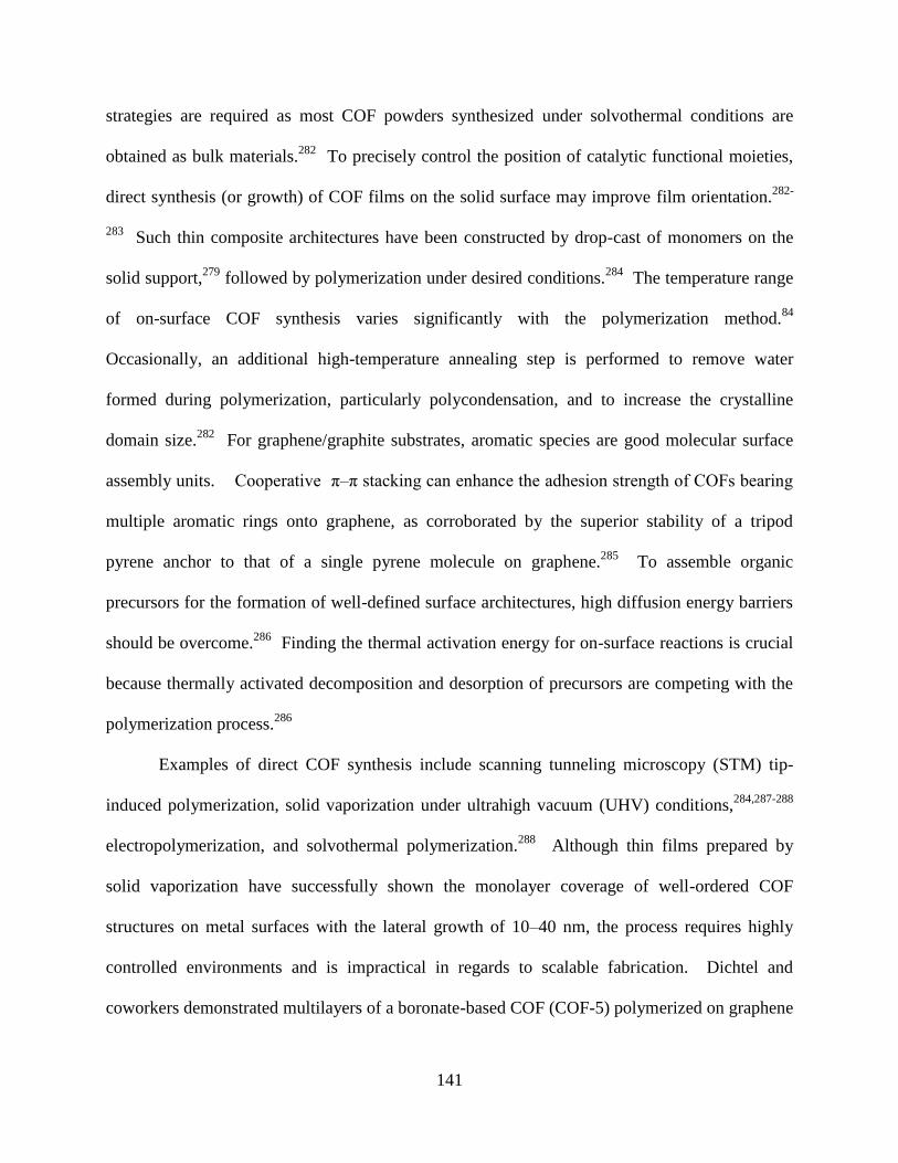
141
strategies are required as most COF powders synthesized under solvothermal conditions are
obtained as bulk materials.282
To precisely control the position of catalytic functional moieties,
direct synthesis (or growth) of COF films on the solid surface may improve film orientation.282-
283 Such thin composite architectures have been constructed by drop-cast of monomers on the
solid support,279
followed by polymerization under desired conditions.284
The temperature range
of on-surface COF synthesis varies significantly with the polymerization method.84
Occasionally, an additional high-temperature annealing step is performed to remove water
formed during polymerization, particularly polycondensation, and to increase the crystalline
domain size.282
For graphene/graphite substrates, aromatic species are good molecular surface
assembly units. Cooperative π–π stacking can enhance the adhesion strength of COFs bearing
multiple aromatic rings onto graphene, as corroborated by the superior stability of a tripod
pyrene anchor to that of a single pyrene molecule on graphene.285
To assemble organic
precursors for the formation of well-defined surface architectures, high diffusion energy barriers
should be overcome.286
Finding the thermal activation energy for on-surface reactions is crucial
because thermally activated decomposition and desorption of precursors are competing with the
polymerization process.286
Examples of direct COF synthesis include scanning tunneling microscopy (STM) tip-
induced polymerization, solid vaporization under ultrahigh vacuum (UHV) conditions,284,287-288
electropolymerization, and solvothermal polymerization.288
Although thin films prepared by
solid vaporization have successfully shown the monolayer coverage of well-ordered COF
structures on metal surfaces with the lateral growth of 10–40 nm, the process requires highly
controlled environments and is impractical in regards to scalable fabrication. Dichtel and
coworkers demonstrated multilayers of a boronate-based COF (COF-5) polymerized on graphene
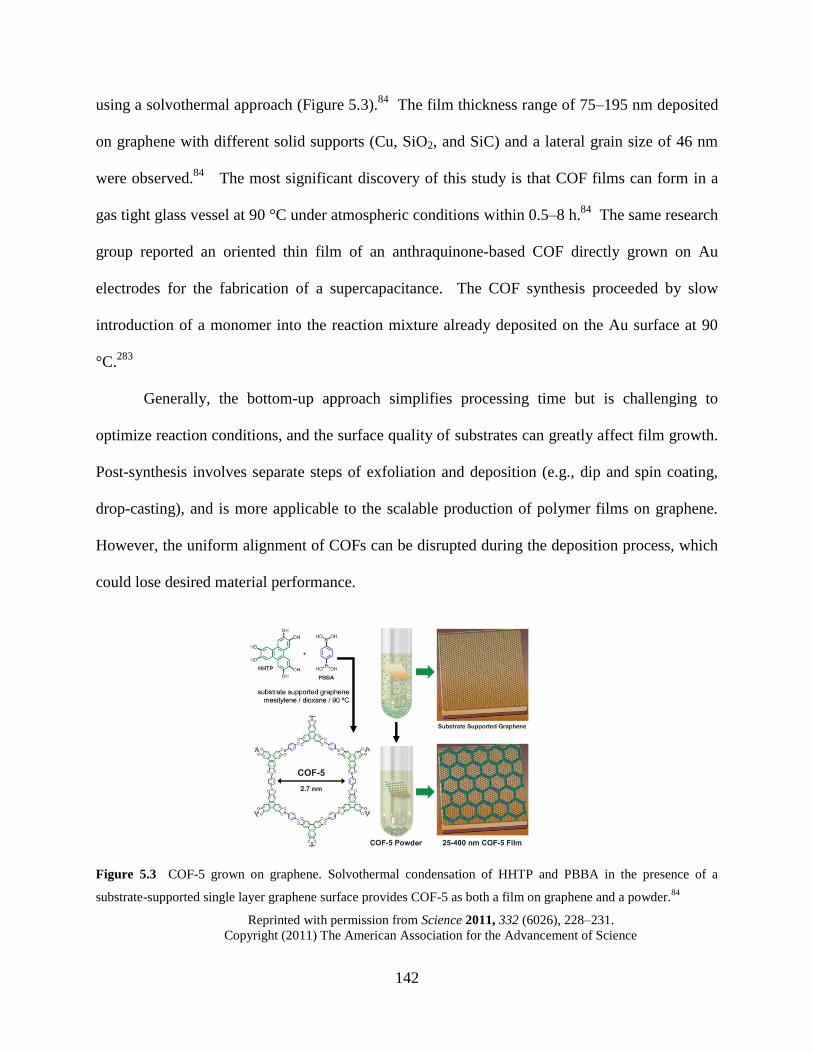
142
using a solvothermal approach (Figure 5.3).84
The film thickness range of 75–195 nm deposited
on graphene with different solid supports (Cu, SiO2, and SiC) and a lateral grain size of 46 nm
were observed.84
The most significant discovery of this study is that COF films can form in a
gas tight glass vessel at 90 °C under atmospheric conditions within 0.5–8 h.84
The same research
group reported an oriented thin film of an anthraquinone-based COF directly grown on Au
electrodes for the fabrication of a supercapacitance. The COF synthesis proceeded by slow
introduction of a monomer into the reaction mixture already deposited on the Au surface at 90
°C.283
Generally, the bottom-up approach simplifies processing time but is challenging to
optimize reaction conditions, and the surface quality of substrates can greatly affect film growth.
Post-synthesis involves separate steps of exfoliation and deposition (e.g., dip and spin coating,
drop-casting), and is more applicable to the scalable production of polymer films on graphene.
However, the uniform alignment of COFs can be disrupted during the deposition process, which
could lose desired material performance.
Figure 5.3 COF-5 grown on graphene. Solvothermal condensation of HHTP and PBBA in the presence of a
substrate-supported single layer graphene surface provides COF-5 as both a film on graphene and a powder.84
Reprinted with permission from Science 2011, 332 (6026), 228–231.
Copyright (2011) The American Association for the Advancement of Science
143
5.2.3 Fabrication of porous graphene
Porous graphene comprises single- or few-layer graphene, an important substrate for
nanoelectronics.289
The fabrication of porous graphene (i.e., holey graphene,117,290-291
graphene
nanomesh,292-294
graphene foam295-296
) began mainly for modification of the intrinsic zero energy
bandgap of semimetallic graphene.32,292
Recently, porous graphene-based gas separation
membranes have been developed, which exhibit high separation capacity and good mechanical
properties.297-299
A high-density array of nanoscale holes in large graphene sheets imparts
semiconducting characteristics that are lacking in pristine graphene.32,293
The energy band gap
can be tuned by controlling the neck width between pores, the size and shape of pores, and the
pore lattice symmetry.291,293
Edges of periodic or quasi-periodic holes facilitate faster electron
transport and higher electrocatalytic activity.293
With high field transport efficiency and on–off
ratios, porous graphene has shown great promise for high-performance FET devices and
bio/chemical sensing.293
A variety of fabrication methods have been reported, including chemical (e.g., KOH,300
HNO3 oxidation,301
and catalytic oxidation117,126,302
) and physical etching (e.g., photo-, electron
beam, oxygen plasma, and ion irradiation).289,294
Top-down nanolithography, such as block
copolymer lithography,292
self-assembled monolayers of colloidal nano- and microspheres,32
and
photocatalytic patterning,302
provides patterned graphene with high resolution.289
Most
lithography processes involve graphene mounted on a solid support before patterning, so that
isolation of free standing patterned graphene is unnecessary (Figure 5.4a).293
Lithographic
patterning affords the pore size range from meso (2–50 nm) to microscale (<2 nm),293
but have
issues of high cost and low throughput.303
A few approaches including metal NPs as hard
templates under high temperatures (>500 °C) or using aggressive chemicals such as HF were
144
reported, but these conditions are not ideal for industrial applications (Figure 5.4b).303
Non-
lithographic methods using catalysts or reagents in solution are environmentally benign and may
be more applicable in industry, but isolation and transfer of free standing graphene sheets
without creating wrinkles is extremely difficult.126,301
In addition, the generation of regular holey
structures on selective sites is almost impossible given the current advancement of the
technique.290,301
Future directions for pattering graphene/graphite should aim at developing
simple synthetic routes that are environmentally benign and industrially applicable.
Figure 5.4 Patterned porous graphene. (a) Block copolymer lithography. Pristine graphene is covered by a thin
layer of evaporated SiOx (protecting layer) and a spin-coated block copolymer poly(styrene block-methyl
methacrylate). After annealing, the porous polystyrene (PS) matrix is formed as a template. Fluoride-based reactive
ion etching (RIE) reveals the SiOx hard mask. Etching graphene by O2 plasma and HF dip cleaning provides
graphene nanomesh. TEM images below show a periodicity of 39 nm and a neck width of 7.1 nm (left) and a
periodicity of 27 nm and a neck width of 9.3 nm (right) prepared by the different MWs (77 kDa and 48 kDa,
respectively) of block copolymer.292
(b) Uneven sizes of holes on graphene by catalytic air oxidation with AgNPs.125
Ref. 292. Reprinted with permission from Nat. Nanotechnol. 2010, 5 (3), 190–194.
Copyright (2010) Nature Publishing Group.
Ref. 125. Reprinted with permission from Nanoscale 2013, 5 (17), 7814–7824.
Copyright (2013) Royal Society of Chemistry.
145
5.3 EXPERIMENTAL
5.3.1 Synthesis and characterization of Fe-DpaTph-COF
Iron(III)-tetrakis(4-aminophenyl)porphyrin chloride (Fe-TAP-Cl) was prepared with iron(II)
chloride tetrahydrate (FeCl2∙4H2O) and 5,10,15,20-tetrakis(4-aminophenyl)porphyrin.304
The
isolated 2 (8 mg, 0.01 mmol) and 2,3-dihydroxybenzene-1,4-dicarbaldehyde (3.4 mg, 0.02
mmol) were transferred to a glass tube (OD: 1 mm, H: 18 cm) dispersed in dimethylacetamide
(DMA) (1.5 mL) and 1,2-dichlorobenzene (0.1 mL). After the starting compounds were
completely dissolved, 6.0 M acetic acid (0.2 mL) was added to the reaction mixture and
sonicated for 1 min, which precipitated out some of the starting compounds. The reaction tube
was degassed by three freeze-pump-thaw cycles at 77 K (liquid N2) and brought to room
temperature for flame seal. Then the tube was stored in a convection oven at 120 °C for 6 d.
The product was collected after two wash cycles using CH2Cl2 (100 mL) and MeOH (100 mL)
over a PTFE membrane Millipore filter (0.2 μm) and dry over high vacuum for 24 h (yield,
76%). FTIR (KBr, ATR) υmax, 3666–2826, 1646, 1617, 1512, 1414, 1347, 1289, 1184, 1068,
1002, 813, 715, 574. PXRD, 2θ (°) found: 3.70, 7.08–7.76 (br), 25.8, 44.64. d spacing (Å)
calc’d: 23.9, 12.5–11.4 (br), 3.45, 2.03 (br, weak).
To grow the metallated COF (Fe(III)-DhaTph-COF), about 5–8 pieces of mechanically
cleaved HOPG (0.5 mm × 0.5 mm) flakes were placed with the reaction mixture in a flame
sealed test tube. After 6 d of condensation under the solvothermal condition, Fe-DhaTph-COF-
deposited HOPG flakes were collected. A black powder of Fe-DhaTph-COF was collected from
the same reaction batch for further characterization. The Fe-DhaTph-COF catalyst was also
prepared by complexation of Fe(III) with DhaTph-COF in a separate post-polymerization step.304
146
DhaTph-COF (2.5 mg) was allowed to stir in NMP (7.0 mL) under N2 at 160 °C for 24 h. Then
FeCl2∙4H2O (32 mg, 0.16 mmol) was added to the DhaTph-COF solution and stirred for 24 h for
complexation. After the reaction mixture was cooled to room temperature, the crude product
was washed with H2O and MeOH over a milipore filter (pore size: 0.2 μm). A black solid
powder was collected and dried in vacuo. A solution of Fe-DhaTph-COF (1.2 mg) was prepared
in DMF 1.0 mL). After stirring for 2 h at 80 °C, the metallated COF solution was deposited on
HOPG flakes by either dip-coating or drop-casting and was allowed to dry over a hot plate at 50
°C.
5.3.2 Fabrication of porous graphene
Deposition of Fe-DhaTph-COF. The solution of Fe-DhaTph-COF in post-polymerization
process was prepared in DMF (1 mg/1 mL). Mechanically cleaved HOPG flakes were
sequentially rinsed with DI H2O, ethanol, and hexanes and then dried in a petri dish on a hot
plate for 24 h at 50 °C. About 100 μL of the solution was drop-cast on a HOPG flakes on a glass
slide and dried at 100 °C. The dip-coating method was performed on clean HOPG flakes that
were completely immersed in the COF solution with tweezers and were stored for about 12 h.
Then the flakes were dried over a hot plate in the same fashion.
Addition of oxidants. A dried Fe-DhaTph-COF on HOPG flake was placed in a 1-dram
vial containing 0.2 mL of acetonitrile or a mixture of acetonitrile: pH 5.0 buffer (1:1, v/v). A 20
μL of H2O2 solution 30% (w/w) was added, followed by gentle shaking for 30 sec, and the
capped vial was placed in a sand bath at 65 °C. The same amount H2O2 solution was replenished
at every 6 h (20 μL per addition). When NaOCl was employed as a co-oxidant, 20 μL of a
147
NaOCl solution (available chlorine 10–15 %) was added after 2 h of the H2O2 addition and kept
at the same temperature. When the oxidative patterning was completed, the oxidant-treated COF
on HOPG was removed by the wash cycle of NaOH (5 M solution), HCl (7M solution), NaOH
(1 M solution), DI water, and acetone. The sample was stored in each different solution of the
acid and the base over 12 h with occasional stirring. The rinsed HOPG was dried at 50 °C and
the smooth side of HOPG flake was used for characterization.
Exfoliation of patterned HOPG flakes with phosphoric acid (H3PO4). An oxidized
HOPG flake was transferred to a 1-dram vial and 2 mL of DMF was added to the vial. After
bath sonication for 10–30 min, the HOPG suspended DMF solution was collected with a
disposable pipette and transferred to a new 1-dram vial. After DMF was dried off at 120 °C,
concentrated phosphoric acid (0.5 mL) was transferred to the vial containing the small exfoliated
HOPG particles. The mixture of HOPG and phosphoric acid was ground with a glass rod and
heated in air at 125 °C for about 12 h. Fresh DMF (2 mL) was added to the acid treated HOPG
and bath sonicated for about 30 min, followed by stirring in total 6 mL of DMF at room
temperature.
148
5.4 RESULTS AND DISCUSSION
5.4.1 Characterization of Fe-DhaTph-COF
On-surface synthesis of DhaTph-COF on HOPG was attempted in a gas-tight vessel under
atmospheric conditions at 90 °C using the same solvent condition and monomer stoichiometry
reported in the previous study.306
However, there was no sign of COF formation after 4 d based
on the crude mixture collected from the bottom of the reaction vessel. Instead, a flame-sealed
pyrex tube was used, in which HOPG flakes were immersed in the reaction mixture before the
flame seal. The COF reaction proceeded in vacuo at 120 °C, and a DhaTph-COF powder and
COF-deposited HOPG flakes were collected after 6 d. Under the same condition, the metallated
porphyrin COF (Fe-DhaTph-COF) was prepared with an amine functionalized metalloporphyrin
(Fe-TPA-Cl) monomer. The blue shift in the Soret bands of porphyrin (from 426 to 418 nm)
shown in the UV–Vis spectra confirms the Fe(III) complexation with the porphyrin monomer
(Figure 5.9). FTIR spectra of both DhaTph-COF and Fe-DhaTph-COF show the presence of an
imine group at 1617 cm−1
(Figure 5.11b–d). The Fe-DhaTph-COFs samples were synthesized by
different methods: (1) Polymerization with Fe-TPA-Cl, and (2) Polymerization of DhaTph-COF,
followed by Fe(III)-complexation with DhaTph-COF. Both the spectra of Fe-TPA-Cl show less
defined, broad imine peaks and a very distinct O–H stretching at 3666–2826 cm−1
in contrast to
DhaTph-COF. The different procedures for synthesizing Fe-DhaTph-COF are further described
in Ch.5.6.2.
The surface characteristics of Fe-DhaTph-COF and DhaTph-COF deposited on HOPG
were very different. The dark purple layer of DhaTph-COF on HOPG exhibited a much
smoother surface than dark brown Fe-DhaTph-COF. AFM micrographs confirm the different
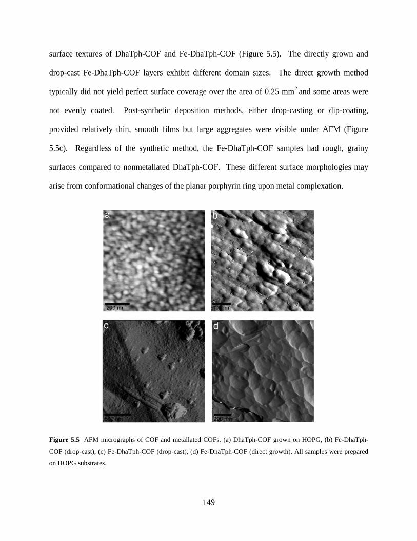
149
surface textures of DhaTph-COF and Fe-DhaTph-COF (Figure 5.5). The directly grown and
drop-cast Fe-DhaTph-COF layers exhibit different domain sizes. The direct growth method
typically did not yield perfect surface coverage over the area of 0.25 mm2
and some areas were
not evenly coated. Post-synthetic deposition methods, either drop-casting or dip-coating,
provided relatively thin, smooth films but large aggregates were visible under AFM (Figure
5.5c). Regardless of the synthetic method, the Fe-DhaTph-COF samples had rough, grainy
surfaces compared to nonmetallated DhaTph-COF. These different surface morphologies may
arise from conformational changes of the planar porphyrin ring upon metal complexation.
Figure 5.5 AFM micrographs of COF and metallated COFs. (a) DhaTph-COF grown on HOPG, (b) Fe-DhaTph-
COF (drop-cast), (c) Fe-DhaTph-COF (drop-cast), (d) Fe-DhaTph-COF (direct growth). All samples were prepared
on HOPG substrates.
150
5.4.2 Oxidative conditions for patterning graphite
As demonstrated in the MPO-catalyzed oxidation where an oxidant such as H2O2 converts
Fe(III) into a reactive intermediate species Fe(IV=O•) and produces hydroxyl radical,90, 110
we
hypothesize that synthetic Fe(III)-porphyrin catalysts would oxidize graphite in a similar fashion.
The oxidative condition was adjusted based on the Fe(III)-catalyzed oxidation of benzene and
polycyclic aromatic hydrocarbons (PAHs).275-276
The use of co-oxidants H2O2/NaOCl with a
synthetic porphyrin catalyst is unprecedented although the noncatalytic oxidation of organic
substrates has been reported.307-308
Nonetheless, we sought to examine if the role of hypochlorite
(−OCl) formed in situ in the MPO-catalytic cycle would be also applicable to the COF-catalytic
system. The catalytic cycle of Fe(III) was activated by addition of H2O2 at every 4 h. The co-
oxidant system was tested by addition of NaOCl 2 h after the H2O2-activation. Upon addition of
NaOCl, it immediately reacted with extra H2O2 remaining in the solution, resulting in vigorous
formation of oxygen gas that can initiate singlet oxygen-mediated oxidation.307-308
After the metallated COF was removed from the HOPG surface, the morphology of
HOPG was analyzed by TEM and AFM. The pristine HOPG sheets exfoliated with H3PO4309
do
not exhibit significant defects (Figure 5.6a, d, and g). In contrast, the HOPG samples treated
with oxidants (H2O2/NaOCl) at 65 °C clearly show dense holes on the surface. Catalytic
oxidation on the Fe-DhaTph-COF deposited graphite resulted in the formation of continuous
hole arrays of 4–50 nm in diameter under TEM (Figure 5.6c), consistent with holes of 8–40 nm
found in the AFM image (Figure 5.6f). This patterned surface suggests that the Fe(III) ions
coordinated to the COF were anchored to the graphite surface and facilitated oxidative
degradation. Based on the pore size of DhaTph-COF (ca. 2.3 nm) reported in the previous
study,306
the hypothetical hole periodicity can be roughly estimated by measuring the distance
151
between Fe-DhaTph-COF catalytic centers. The average hole periodicity of 8.3 nm and the
average neck width (the smallest edge-to-edge distance between two neighboring holes) of 2.0
nm measured on TEM images were larger than the periodicity of Fe(III) catalytic center (i.e., the
distance between porphyrin rings). The elongated shapes suggest that defect formation laterally
propagated over the nearby graphitic surface.
When a pH 5.0 acetate buffer solution was mixed with acetonitrile (1:1, v/v) to examine
the pH effect on HOCl formation over −OCl, samples exhibited large, random holes (Figure
5.12a–c and e). The hole nanoarrays were also created by H2O2-activated oxidation (Figure
5.12d and f), but a larger amount of oxidant was required to generate a significant holey structure
than the co-oxidant system. The co-oxidant system of H2O2/NaOCl is efficient for a short-term
treatment probably because hypochlorite can induce reactive singlet oxygen-mediated oxidation
by insertion of peroxy groups (O–O) on the graphitic carbons without a catalyst. Once sp2
carbons are substituted with oxygen-containing groups, bond cleavage of C–C can undergo
readily.307
As hypochlorite can serve solely as an effective oxidant under noncatalytic
conditions, we conducted a control reaction with only hypochlorite (−OCl). However, no
repeating holey structure was observed, suggesting that the Fe-DhaTph-COF catalytic systems
were critical to generating site-selectivity for patterning. To verify our initial hypothesis of Fe-
DhaTph-COF’s bifunctional role of catalyst–template, we investigated the catalytic activity of
iron(III)-tetrakis(4-aminophenyl)porphyrin chloride (Fe-TAP-Cl) that may be self-assembled
into nanoaggregates with sufficient surface coverage on HOPG (Figure 5.13).310-313
The
excellent catalytic performance of small porphyrin units noncovalently bound to graphene was
reported although Fe(III) porphyrin centers were randomly positioned on the graphene surface.134
Nevertheless, the interactions and morphology of metal–ligand complexes were relatively
152
difficult to control in small-molecule catalyst systems.279
TEM (Figure 5.6b) and AFM (Figure
5.6e) images show that Fe-TAP-Cl-catalyzed oxidation generated sparse holes, very different
from the patterned surface with the metallated COF. This uneven distribution may suggest poor
adhesion between HOPG and Fe-TAP-Cl aggregates (Figure 5.13), revealing the dynamic nature
of association/dissociation when they are in contact with solvents. It is inconclusive whether
some large holes observed under AFM resulted from those catalyst aggregates.
To successfully realize the copy–print concept in the fabrication of multiple holey
graphene sheets, defect formation needs to propagate vertically and create regular nanochannel
arrays through several graphitic layers. AFM height analysis in Figure 5.14 reveals that the
vertical channel propagated from the top surface is about 1–3 nm (up to ~12 layers of graphene).
However, the oxidation process appears to have also laterally expanded the defect area on the
same plane of graphene to some extent, unavoidably generating some large holes. The lateral
propagation is more pronounced near the metal catalytic center than the inner graphite. In
addition, the irregular shapes might have resulted from the disintegrating COF catalyst under the
oxidative condition. Thus the morphologies of Fe-DhaTph-COF deposited on HOPG before and
after oxidation were analyzed with AFM. As shown in Figure 5.15, much of the COF catalyst
remained intact under the oxidative condition. However, it is unclear if the degradation products
or intermediate species of graphite that were produced during oxidation reacted with the inner
COF layer, thereby disrupting the metal catalytic center.
The number of patterned graphene layers was also estimated from exfoliated samples
(Figure 5.6g–i). The exfoliation of the pristine HOPG sample with phosphoric acid was not
greatly effective. After an extensive amount of time of sonication (6 h) and stirring (2 d) in
DMF at room temperature, the pristine HOPG sample afforded graphene sheets of 2–4 nm
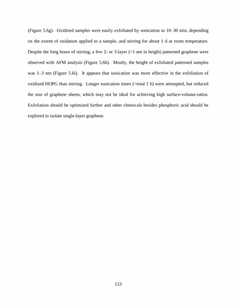
153
(Figure 5.6g). Oxidized samples were easily exfoliated by sonication in 10–30 min, depending
on the extent of oxidation applied to a sample, and stirring for about 1 d at room temperature.
Despite the long hours of stirring, a few 2- or 3-layer (<1 nm in height) patterned graphene were
observed with AFM analysis (Figure 5.6h). Mostly, the height of exfoliated patterned samples
was 1–3 nm (Figure 5.6i). It appears that sonication was more effective in the exfoliation of
oxidized HOPG than stirring. Longer sonication times (>total 1 h) were attempted, but reduced
the size of graphene sheets, which may not be ideal for achieving high surface-volume-ratios.
Exfoliation should be optimized further and other chemicals besides phosphoric acid should be
explored to isolate single-layer graphene.
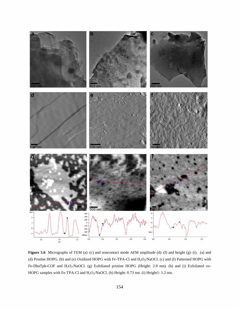
154
Figure 5.6 Micrographs of TEM (a)–(c) and noncontact mode AFM amplitude (d)–(f) and height (g)–(i). (a) and
(d) Pristine HOPG. (b) and (e) Oxidized HOPG with Fe-TPA-Cl and H2O2/NaOCl. (c) and (f) Patterned HOPG with
Fe-DhaTph-COF and H2O2/NaOCl. (g) Exfoliated pristine HOPG (Height: 2.9 nm). (h) and (i) Exfoliated ox-
HOPG samples with Fe-TPA-Cl and H2O2/NaOCl. (h) Height: 0.73 nm. (i) Height1: 1.2 nm.
155
5.4.3 Characterization of patterned graphite with FTIR and Raman spectroscopy
Changes in the functional group of HOPG before and after oxidation were analyzed using FTIR.
The spectra of patterned HOPG and freshly cleaved pristine HOPG samples are almost identical
(Figure 5.7a). Generally, IR absorption spectra for HOPG and graphite samples are featureless,
but the overall band profile of pristine HOPG appears close to those of graphene and graphene
oxide.314-315
The patterned HOPG shows a new peak at 1705 cm−1
can be attributed to C=O
stretching modes due to oxidation.316
Raman spectroscopy was utilized to quantify the number of newly formed sp3 defects
relative to pristine sp2 graphitic carbons and characterize the defect type. Figure 5.7b shows the
average ID/IG of 0.31 for H2O2/NaOCl-treated samples whereas only a residual peak (1331 cm−1
)
is shown in the pristine HOPG spectrum. The peak width (fwhm) of D′ band at 1607–1635
cm−1
, indicative of the formation of vacancy-like defects, appears far more pronounced than
those of other samples. The spectrum of the small porphyrin unit (Fe-TAP-Cl)-catalyzed
oxidation shows a clear indication of sp3 defect formation despite the low average ID/IG of 0.15
and the barely noticeable D′ peak. The TEM image in Figure 5.6b shows that the self-assembled
metalloporphyrin (Fe-TAP-Cl) aggregates can catalyze oxidation on the HOPG surface and
generate vacancy-like defects. However, the uneven distribution of holes could result in a very
subtle D′ band. This inconsistency may be due to the skewing of data from sampling spots
randomly selected for Raman analysis. Table 5.1 lists the ID/IG values of the samples catalyzed
by Fe-DhaTph-COF. To investigate the difference in catalytic activity between direct growth
and drop-casting of Fe-DhaTph-COF, the average ID/IG values are compared. The direct growth
method has slightly higher ID/IG values (higher degrees of oxidation) than drop-casting for both
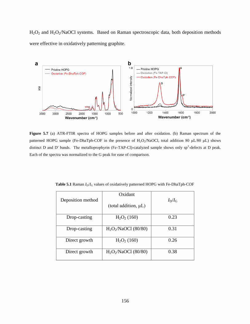
156
H2O2 and H2O2/NaOCl systems. Based on Raman spectroscopic data, both deposition methods
were effective in oxidatively patterning graphite.
Figure 5.7 (a) ATR-FTIR spectra of HOPG samples before and after oxidation. (b) Raman spectrum of the
patterned HOPG sample (Fe-DhaTph-COF in the presence of H2O2/NaOCl, total addition 80 μL/80 μL) shows
distinct D and D′ bands. The metalloprophyrin (Fe-TAP-Cl)-catalyzed sample shows only sp3-defects at D peak.
Each of the spectra was normalized to the G peak for ease of comparison.
Table 5.1 Raman ID/IG values of oxidatively patterned HOPG with Fe-DhaTph-COF
Deposition method
Oxidant
(total addition, μL)
ID/IG
Drop-casting H2O2 (160) 0.23
Drop-casting H2O2/NaOCl (80/80) 0.31
Direct growth H2O2 (160) 0.26
Direct growth H2O2/NaOCl (80/80) 0.38
157
5.5 CONCLUSION
We demonstrated a new chemical patterning method of utilizing an Fe(III) prophyrin COF as a
surface catalyst and a template on HOPG. Few-layer patterned graphene sheets exhibited holey
structures after treatment with H2O2 or H2O2/NaOCl. AFM imaging analysis showed that the
oxidation process propagated vertically (oxidative perforation 12 layers of graphene), forming
multiple layers of patterned graphene. The size and shape of holes varied with the oxidative
condition and the proximity to the catalytic site. Metallated COFs can be an effective, robust
catalyst for creating holes on graphitic carbon network under mild catalytically oxidative
conditions that can be potentially translated into industrial processes. The copy-print concept of
oxidative patterning–exfoliation will allow for facile processing and scalable production of
patterned holey graphene. Future studies should focus on tuning the oxidative condition to
achieve precise, uniform hole morphology. In addition, exfoliation methods should be improved
to produce single-layer graphene.
158
5.6 SUPPORTING INFORMATION
5.6.1 Materials and instrumentation
Highly ordered pyrolytic graphite (HOPG SPI-1 Grade: #439HP-AB) was purchased from SPI
Supplies (Westchester, PA). 5,10,15,20-tetrakis(4-aminophenyl)porphyrin was obtained from
TCI America. Hydrogen peroxide (30% in solution) was purchased from EMD Chemical. All
other chemicals were obtained from Sigma Aldrich and used without further purification. All
reaction solvents were anhydrous reagent graded. Silica gel for column chromatography was
purchased from Selecto Scientific. Thin layer chromatography was performed on Merck TLC
plates pre-coated with silica gel 60 F254. Visualization of the developed plates was performed
by fluorescence quenching or by phosphomolybdic acid (PMA) stain.
Fourier Transform spectroscopy (FTIR) was performed using an IR-Prestige
spectrophotometer (Shimadzu Scientific) outfitted with an EasiDiff accessory (Pike
Technologies). Solid samples were ground with KBr to prepare a homogenous mixture. Spectra
were collected for 32 scans at 2 cm−1
resolution. Powder x-ray diffraction (PXRD) was recorded
on a Bruker X8 Prospector Ultra equipped with a Bruker Smart Apex CCD diffractometer and a
Copper micro-focus X-ray source employing Cu Kα radiation at 40 kV, 40 mA. A ground
sample was loaded in a capillary tube (D: 1 mm) for analysis. The size and the morphology were
analyzed with Transmission Electron Microscopy (FEI-Morgani, 80 keV). All TEM samples
were prepared by drop-casting 3.5 µL of a sample onto a lacey carbon films/400 mesh copper
grid and dried under ambient conditions over 24 h. An Asylum MFP-3D Atomic Force
Microscope (AFM) was utilized with high resolution probes (Hi’Res-C14/Cr-Au) purchased
from MikroMasch. Patterned HOPG samples were directly mounted on a metal disc using
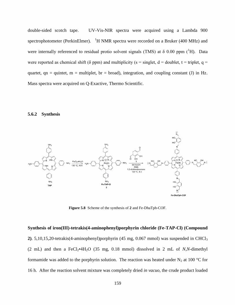
159
double-sided scotch tape. UV-Vis-NIR spectra were acquired using a Lambda 900
spectrophotometer (PerkinElmer). 1H NMR spectra were recorded on a Bruker (400 MHz) and
were internally referenced to residual protio solvent signals (TMS) at δ 0.00 ppm (1H). Data
were reported as chemical shift (δ ppm) and multiplicity (s = singlet, d = doublet, t = triplet, q =
quartet, qn = quintet, m = multiplet, br = broad), integration, and coupling constant (J) in Hz.
Mass spectra were acquired on Q-Exactive, Thermo Scientific.
5.6.2 Synthesis
Figure 5.8 Scheme of the synthesis of 2 and Fe-DhaTph-COF.
Synthesis of iron(III)-tetrakis(4-aminophenyl)porphyrin chloride (Fe-TAP-Cl) (Compound
2). 5,10,15,20-tetrakis(4-aminophenyl)porphyrin (45 mg, 0.067 mmol) was suspended in CHCl3
(2 mL) and then a FeCl2•4H2O (35 mg, 0.18 mmol) dissolved in 2 mL of N,N-dimethyl
formamide was added to the porphyrin solution. The reaction was heated under N2 at 100 °C for
16 h. After the reaction solvent mixture was completely dried in vacuo, the crude product loaded
160
on a deactivated Al2O3 column was purified sequentially using 100% acetone and a mixture of
ethyl acetate : acetonitrile : methanol (3:1:1, v/v/v) gave a dark green powder of Fe-TAP-Cl
(yield, 64%). HRMS (Multimode-ESI/APCI) calc’d for C44H32N8ClFe [MH]+=763.17824; found
763.17590. FTIR (KBr, ATR) υmax, 3426, 3365, 3222, 3028, 2957, 2924, 2854, 1668, 1610,
1515, 1339, 1290, 1202, 1000, 875, 804 cm−1
. UV-Vis (CH3CN) λmax, 244, 315, 419, 576, 623
nm.
Synthesis of 2,3-dihydroxybenzene-1,4-dicarbaldehyde (Compound 1). 1 was
prepared by the two-step synthesis based on the procedures previously reported.1 To improve
the purity, the crude product was vigorously stirred in 15% sodium thiosulfate solution with
addition of dichloromethane for 6 h. The organic layer was dried over Mg2SO4 and filtered, and
then the solvent was dried in vacuo. Purification through silica gel flash chromatography
(dichloromethane : methanol : acetic acid = 98:1:1) and further recrystallization from 100%
hexanes afforded 83% yield as a yellow solid. mp 100–101 °C. 1H NMR (400 MHz, CDCl3, δ)
7.28 (s, 2H), 10.03 (s, 2H), 10.91 (s, 2H). 13
C NMR (125 MHz, CDCl3, δ) 196.3, 150.9, 123.2,
122.2. IR (KBr, ATR) 3371, 3128, 3051, 2866, 2769, 1689, 1654, 1562, 721 cm−1
. HRMS
(Multimode-ESI/APCI) calc’d for C8H6O4 [MH]+ = 167.08335; found 167.08245.
Synthesis of Fe-DhaTph-COF. The isolated 2 (8 mg, 0.01 mmol) and 2,3-
dihydroxybenzene-1,4-dicarbaldehyde (3.4 mg, 0.02 mmol) were transferred to a glass tube
(OD: 1 mm, H: 18 cm) dispersed in dimethylacetamide(DMA) (1.5 mL) and 1,2-
dichlorobenzene (0.1 mL). After the starting compounds were completely dissolved, 6.0 M
acetic acid (0.2 mL) was added to the reaction mixture and sonicated for 1 min, which
precipitated out some of the starting compounds. The reaction tube was degassed by three
freeze-pump-thaw cycles at 77 K (liquid N2) and brought to room temperature for flame seal.
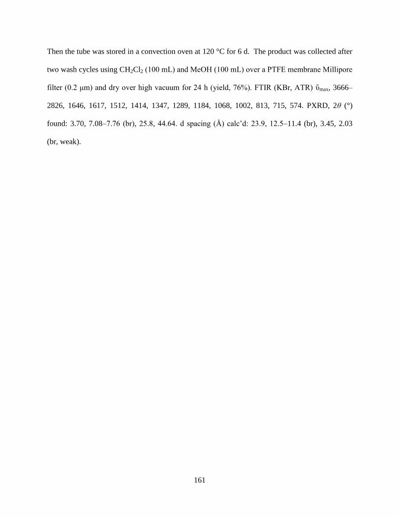
161
Then the tube was stored in a convection oven at 120 °C for 6 d. The product was collected after
two wash cycles using CH2Cl2 (100 mL) and MeOH (100 mL) over a PTFE membrane Millipore
filter (0.2 μm) and dry over high vacuum for 24 h (yield, 76%). FTIR (KBr, ATR) υmax, 3666–
2826, 1646, 1617, 1512, 1414, 1347, 1289, 1184, 1068, 1002, 813, 715, 574. PXRD, 2θ (°)
found: 3.70, 7.08–7.76 (br), 25.8, 44.64. d spacing (Å) calc’d: 23.9, 12.5–11.4 (br), 3.45, 2.03
(br, weak).
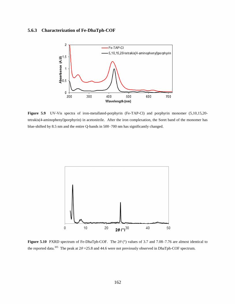
162
5.6.3 Characterization of Fe-DhaTph-COF
Figure 5.9 UV-Vis spectra of iron-metallated-porphyrin (Fe-TAP-Cl) and porphyrin monomer (5,10,15,20-
tetrakis(4-aminophenyl)porphyrin) in acetonitrile. After the iron complexation, the Soret band of the monomer has
blue-shifted by 8.5 nm and the entire Q-bands in 500–700 nm has significantly changed.
Figure 5.10 PXRD spectrum of Fe-DhaTph-COF. The 2θ (°) values of 3.7 and 7.08–7.76 are almost identical to
the reported data.305
The peak at 2θ =25.8 and 44.6 were not previously observed in DhaTph-COF spectrum.
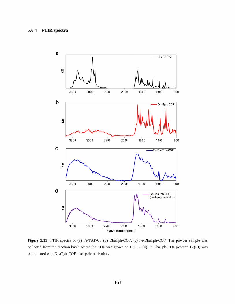
163
5.6.4 FTIR spectra
Figure 5.11 FTIR spectra of (a) Fe-TAP-Cl, (b) DhaTph-COF, (c) Fe-DhaTph-COF: The powder sample was
collected from the reaction batch where the COF was grown on HOPG. (d) Fe-DhaTph-COF powder: Fe(III) was
coordinated with DhaTph-COF after polymerization.
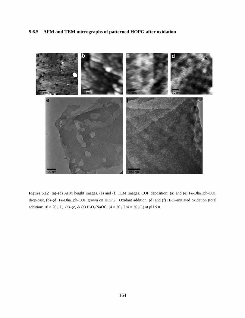
164
5.6.5 AFM and TEM micrographs of patterned HOPG after oxidation
Figure 5.12 (a)–(d) AFM height images. (e) and (f) TEM images. COF deposition: (a) and (e) Fe-DhaTph-COF
drop-cast, (b)–(d) Fe-DhaTph-COF grown on HOPG. Oxidant addition: (d) and (f) H2O2-initiated oxidation (total
addition: 16 × 20 μL). (a)–(c) & (e) H2O2/NaOCl (4 × 20 μL/4 × 20 μL) at pH 5.0.
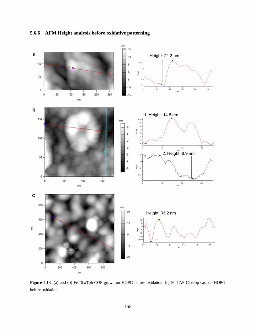
165
5.6.6 AFM Height analysis before oxidative patterning
Figure 5.13 (a) and (b) Fe-DhaTph-COF grown on HOPG before oxidation. (c) Fe-TAP-Cl drop-cast on HOPG
before oxidation.
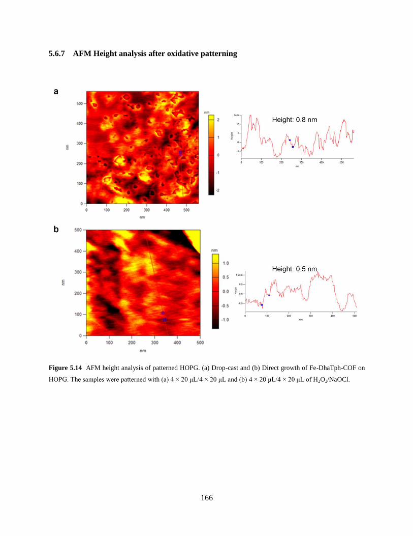
166
5.6.7 AFM Height analysis after oxidative patterning
Figure 5.14 AFM height analysis of patterned HOPG. (a) Drop-cast and (b) Direct growth of Fe-DhaTph-COF on
HOPG. The samples were patterned with (a) 4 × 20 μL/4 × 20 μL and (b) 4 × 20 μL/4 × 20 μL of H2O2/NaOCl.
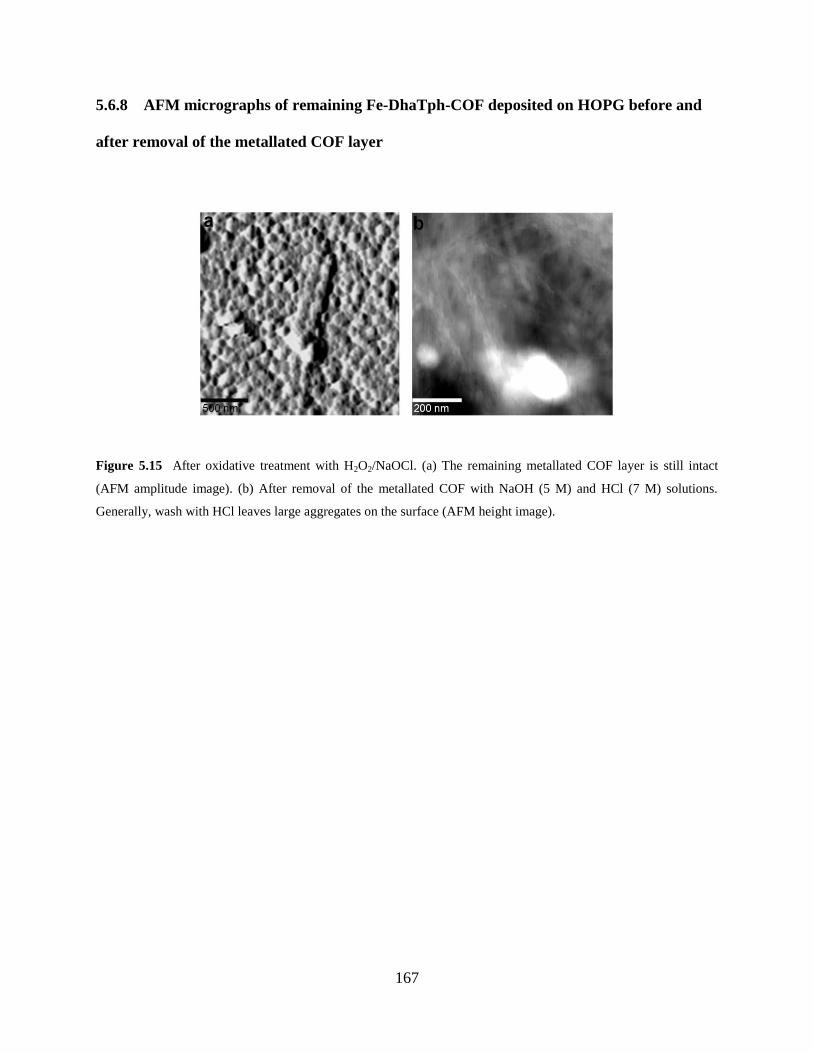
167
5.6.8 AFM micrographs of remaining Fe-DhaTph-COF deposited on HOPG before and
after removal of the metallated COF layer
Figure 5.15 After oxidative treatment with H2O2/NaOCl. (a) The remaining metallated COF layer is still intact
(AFM amplitude image). (b) After removal of the metallated COF with NaOH (5 M) and HCl (7 M) solutions.
Generally, wash with HCl leaves large aggregates on the surface (AFM height image).
168
BIBLIOGRAPHY
1. Jariwala, D.; Sangwan, V. K.; Lauhon, L. J.; Marks, T. J.; Hersam, M. C. Carbon
Nanomaterials for Electronics, Optoelectronics, Photovoltaics, and Sensing. Chem. Soc. Rev.
2013, 42 (7), 2824–2860.
2. Hirsch, A. The Era of Carbon Allotropes. Nat. Mater. 2010, 9 (11), 868–871.
3. Prasek, J.; Drbohlavova, J.; Chomoucka, J.; Hubalek, J.; Jasek, O.; Adam, V.; Kizek, R.
Methods for Carbon Nanotubes Synthesis-Review. J. Mater. Chem. 2011, 21 (40), 15872–15884.
4. Wu, J. S.; Pisula, W.; Müllen, K. Graphenes As Potential Material for Electronics. Chem.
Rev. 2007, 107 (3), 718–747.
5. Hu, M.; Zhao, Z. S.; Tian, F.; Oganov, A. R.; Wang, Q. Q.; Xiong, M.; Fan, C. Z.; Wen,
B.; He, J. L.; Yu, D. L.; Wang, H. T.; Xu, B.; Tian, Y. J. Compressed Carbon Nanotubes: A
Family of New Multifunctional Carbon Allotropes. Sci. Rep. 2013, 3.
6. Georgakilas, V.; Perman, J. A.; Tucek, J.; Zboril, R. Broad Family of Carbon
Nanoallotropes: Classification, Chemistry, and Applications of Fullerenes, Carbon Dots,
Nanotubes, Graphene, Nanodiamonds, and Combined Superstructures. Chem. Rev. 2015, 115
(11), 4744–4822.
7. Ajayan, P. M. Nanotubes from Carbon. Chem. Rev. 1999, 99 (7), 1787–1799.
8. Niyogi, S.; Hamon, M. A.; Hu, H.; Zhao, B.; Bhowmik, P.; Sen, R.; Itkis, M. E.; Haddon,
R. C. Chemistry of Single-Walled Carbon Nanotubes. Accounts. Chem. Res. 2002, 35 (12),
1105–1113.
9. Bandow, S.; Asaka, S.; Saito, Y.; Rao, A. M.; Grigorian, L.; Richter, E.; Eklund, P. C.
Effect of the Growth Temperature on the Diameter Distribution and Chirality of Single-Wall
Carbon Nanotubes. Phys. Rev. Lett. 1998, 80 (17), 3779–3782.
10. Hersam, M. C. Progress towards Monodisperse Single-Walled Carbon Nanotubes. Nat.
Nanotechnol. 2008, 3 (7), 387–394.
11. Zhang, Q.; Huang, J. Q.; Qian, W. Z.; Zhang, Y. Y.; Wei, F. The Road for Nanomaterials
Industry: A Review of Carbon Nanotube Production, Post-Treatment, and Bulk Applications for
Composites and Energy Storage. Small 2013, 9 (8), 1237–1265.
12. Tasis, D.; Tagmatarchis, N.; Bianco, A.; Prato, M. Chemistry of Carbon Nanotubes.
Chem. Rev. 2006, 106 (3), 1105–1136.
13. Karousis, N.; Tagmatarchis, N.; Tasis, D. Current Progress on the Chemical Modification
of Carbon Nanotubes. Chem. Rev. 2010, 110 (9), 5366–5397.
14. Collins, W. R.; Lewandowski, W.; Schmois, E.; Walish, J.; Swager, T. M. Claisen
Rearrangement of Graphite Oxide: A Route to Covalently Functionalized Graphenes. Angew.
Chem. Int. Edit. 2011, 50 (38), 8848–8852.
169
15. Ghosh, S.; Bachilo, S. M.; Weisman, R. B. Advanced Sorting of Single-Walled Carbon
Nanotubes by Nonlinear Density-Gradient Ultracentrifugation. Nat. Nanotechnol. 2010, 5 (6),
443–450.
16. Weisman, R. B.; Bachilo, S. M. Dependence of Optical Transition Energies on Structure
for Single-Walled Carbon Nanotubes in Aqueous Suspension: An Empirical Kataura Plot. Nano
Lett. 2003, 3 (9), 1235–1238.
17. Dresselhaus, M. S.; Dresselhaus, G.; Saito, R. Physics of Carbon Nanotubes. Carbon
1995, 33 (7), 883–891.
18. Jeong, H. K.; Lee, Y. P.; Lahaye, R. J. W. E.; Park, M. H.; An, K. H.; Kim, I. J.; Yang, C.
W.; Park, C. Y.; Ruoff, R. S.; Lee, Y. H. Evidence of Graphitic AB Stacking Order of Graphite
Oxides. J. Am. Chem. Soc. 2008, 130 (4), 1362–1366.
19. Liao, L.; Peng, H. L.; Liu, Z. F. Chemistry Makes Graphene Beyond Graphene. J. Am.
Chem. Soc. 2014, 136 (35), 12194–12200.
20. Ferrari, A. C.; Bonaccorso, F.; Fal'ko, V.; Novoselov, K. S.; Roche, S.; Boggild, P.;
Borini, S.; Koppens, F. H. L.; Palermo, V.; Pugno, N.; Garrido, J. A.; Sordan, R.; Bianco, A.;
Ballerini, L.; Prato, M.; Lidorikis, E.; Kivioja, J.; Marinelli, C.; Ryhanen, T.; Morpurgo, A.;
Coleman, J. N.; Nicolosi, V.; Colombo, L.; Fert, A.; Garcia-Hernandez, M.; Bachtold, A.;
Schneider, G. F.; Guinea, F.; Dekker, C.; Barbone, M.; Sun, Z. P.; Galiotis, C.; Grigorenko, A.
N.; Konstantatos, G.; Kis, A.; Katsnelson, M.; Vandersypen, L.; Loiseau, A.; Morandi, V.;
Neumaier, D.; Treossi, E.; Pellegrini, V.; Polini, M.; Tredicucci, A.; Williams, G. M.; Hong, B.
H.; Ahn, J. H.; Kim, J. M.; Zirath, H.; van Wees, B. J.; van der Zant, H.; Occhipinti, L.; Di
Matteo, A.; Kinloch, I. A.; Seyller, T.; Quesnel, E.; Feng, X. L.; Teo, K.; Rupesinghe, N.;
Hakonen, P.; Neil, S. R. T.; Tannock, Q.; Lofwander, T.; Kinaret, J. Science and Technology
Roadmap for Graphene, Related Two-Dimensional Crystals, and Hybrid Systems. Nanoscale
2015, 7 (11), 4598–4810.
21. Allen, M. J.; Tung, V. C.; Kaner, R. B. Honeycomb Carbon: A Review of Graphene.
Chem. Rev. 2010, 110 (1), 132–145.
22. Huang, X.; Yin, Z. Y.; Wu, S. X.; Qi, X. Y.; He, Q. Y.; Zhang, Q. C.; Yan, Q. Y.; Boey,
F.; Zhang, H. Graphene-Based Materials: Synthesis, Characterization, Properties, and
Applications. Small 2011, 7 (14), 1876–1902.
23. Stankovich, S.; Dikin, D. A.; Piner, R. D.; Kohlhaas, K. A.; Kleinhammes, A.; Jia, Y.;
Wu, Y.; Nguyen, S. T.; Ruoff, R. S. Synthesis of Graphene-Based Nanosheets via Chemical
Reduction of Exfoliated Graphite Oxide. Carbon 2007, 45 (7), 1558–1565.
24. Kosynkin, D. V.; Higginbotham, A. L.; Sinitskii, A.; Lomeda, J. R.; Dimiev, A.; Price, B.
K.; Tour, J. M. Longitudinal Unzipping of Carbon Nanotubes to Form Graphene Nanoribbons.
Nature 2009, 458 (7240), 872–876.
25. Yi, M.; Shen, Z. G. A Review on Mechanical Exfoliation for the Scalable Production of
Graphene. J. Mater. Chem. A 2015, 3 (22), 11700–11715.
26. Ciesielski, A.; Samori, P. Graphene via Sonication Assisted Liquid-Phase Exfoliation.
Chem. Soc. Rev. 2014, 43 (1), 381–398.
27. Xia, Z. Y.; Pezzini, S.; Treossi, E.; Giambastiani, G.; Corticelli, F.; Morandi, V.; Zanelli,
A.; Bellani, V.; Palermo, V. The Exfoliation of Graphene in Liquids by Electrochemical,
Chemical, and Sonication-Assisted Techniques: A Nanoscale Study. Adv. Funct. Mater. 2013, 23
(37), 4684–4693.
170
28. Suk, J. W.; Kitt, A.; Magnuson, C. W.; Hao, Y. F.; Ahmed, S.; An, J. H.; Swan, A. K.;
Goldberg, B. B.; Ruoff, R. S. Transfer of CVD-Grown Monolayer Graphene onto Arbitrary
Substrates. Acs Nano 2011, 5 (9), 6916–6924.
29. Kim, K. S.; Zhao, Y.; Jang, H.; Lee, S. Y.; Kim, J. M.; Kim, K. S.; Ahn, J. H.; Kim, P.;
Choi, J. Y.; Hong, B. H. Large-Scale Pattern Growth of Graphene Films for Stretchable
Transparent Electrodes. Nature 2009, 457 (7230), 706–710.
30. Shin, H. J.; Choi, W. M.; Yoon, S. M.; Han, G. H.; Woo, Y. S.; Kim, E. S.; Chae, S. J.;
Li, X. S.; Benayad, A.; Loc, D. D.; Gunes, F.; Lee, Y. H.; Choi, J. Y. Transfer-Free Growth of
Few-Layer Graphene by Self-Assembled Monolayers. Adv. Mater. 2011, 23 (38), 4392–4397.
31. Zhang, Y.; Zhang, L. Y.; Zhou, C. W. Review of Chemical Vapor Deposition of
Graphene and Related Applications. Accounts. Chem. Res. 2013, 46 (10), 2329–2339.
32. Sinitskii, A.; Tour, J. M. Patterning Graphene through the Self-Assembled Templates:
Toward Periodic Two-Dimensional Graphene Nanostructures with Semiconductor Properties. J.
Am. Chem. Soc. 2010, 132 (42), 14730–14732.
33. Belin, T.; Epron, F. Characterization Methods of Carbon Nanotubes: A Review. Mat. Sci.
Eng. B: Solid 2005, 119 (2), 105–118.
34. Wepasnick, K. A.; Smith, B. A.; Bitter, J. L.; Fairbrother, D. H. Chemical and Structural
Characterization of Carbon Nanotube Surfaces. Anal. Bioanal .Chem. 2010, 396 (3), 1003–1014.
35. Naumov, A. V.; Ghosh, S.; Tsyboulski, D. A.; Bachilo, S. M.; Weisman, R. B. Analyzing
Absorption Backgrounds in Single-Walled Carbon Nanotube Spectra. Acs Nano 2011, 5 (3),
1639–1648.
36. Ferrari, A. C.; Basko, D. M. Raman Spectroscopy As a Versatile Tool for Studying the
Properties of Graphene. Nat. Nanotechnol. 2013, 8 (4), 235–246.
37. Eckmann, A.; Felten, A.; Mishchenko, A.; Britnell, L.; Krupke, R.; Novoselov, K. S.;
Casiraghi, C. Probing the Nature of Defects in Graphene by Raman Spectroscopy. Nano Lett.
2012, 12 (8), 3925–3930.
38. Malard, L. M.; Pimenta, M. A.; Dresselhaus, G.; Dresselhaus, M. S. Raman Spectroscopy
in Graphene. Phys. Rep. 2009, 473 (5–6), 51–87.
39. Coleman, K. S.; Chakraborty, A. K.; Bailey, S. R.; Sloan, J.; Alexander, M. Iodination of
Single-walled Carbon Nanotubes. Chem. Mater. 2007, 19 (5), 1076–1081.
40. Moniruzzaman, M.; Winey, K. I. Polymer Nanocomposites Containing Carbon
Nanotubes. Macromolecules 2006, 39 (16), 5194–5205.
41. Spitalsky, Z.; Tasis, D.; Papagelis, K.; Galiotis, C. Carbon Nanotube-Polymer
Composites: Chemistry, Processing, Mechanical and Electrical Properties. Prog. Polym. Sci.
2010, 35 (3), 357–401.
42. Emrick, T.; Pentzer, E. Nanoscale Assembly into Extended and Continuous Structures
and Hybrid Materials. Npg Asia Materials 2013, 5, e43.
43. Georgakilas, V.; Tiwari, J. N.; Kemp, K. C.; Perrnan, J. A.; Bourlinos, A. B.; Kim, K. S.;
Zboril, R. Noncovalent Functionalization of Graphene and Graphene Oxide for Energy
Materials, Biosensing, Catalytic, and Biomedical Applications. Chem. Rev. 2016, 116 (9), 5464–
5519.
44. Byrne, M. T.; Gun'ko, Y. K. Recent Advances in Research on Carbon Nanotube-Polymer
Composites. Adv. Mater. 2010, 22 (15), 1672–1688.
45. Peng, X. H.; Wong, S. S. Functional Covalent Chemistry of Carbon Nanotube Surfaces.
Adv. Mater. 2009, 21 (6), 625–642.
171
46. Huang, X.; Qi, X. Y.; Boey, F.; Zhang, H. Graphene-Based Composites. Chem. Soc. Rev.
2012, 41 (2), 666–686.
47. Feng, J. T.; Sui, J. H.; Cai, W.; Gao, Z. Y. Microstructure and Mechanical Properties of
Carboxylated Carbon Nanotubes/Poly(L-lactic acid) Composite. J. Compos. Mater. 2008, 42
(16), 1587–1595.
48. Hirsch, A. Functionalization of Single-Walled Carbon Nanotubes. Angew. Chem. Int.
Edit. 2002, 41 (11), 1853–1859.
49. Singh, P.; Campidelli, S.; Giordani, S.; Bonifazi, D.; Bianco, A.; Prato, M. Organic
Functionalisation and Characterisation of Single-Walled Carbon Nanotubes. Chem. Soc. Rev.
2009, 38 (8), 2214–2230.
50. Georgakilas, V.; Otyepka, M.; Bourlinos, A. B.; Chandra, V.; Kim, N.; Kemp, K. C.;
Hobza, P.; Zboril, R.; Kim, K. S. Functionalization of Graphene: Covalent and Non-Covalent
Approaches, Derivatives and Applications. Chem. Rev. 2012, 112 (11), 6156–6214.
51. Banerjee, S.; Hemraj-Benny, T.; Wong, S. S. Covalent Surface Chemistry of Single-
Walled Carbon Nanotubes. Adv. Mater. 2005, 17 (1), 17–29.
52. Zhang, M. F.; Li, Y.; Su, Z. Q.; Wei, G. Recent Advances in the Synthesis and
Applications of Graphene-Polymer Nanocomposites. Polym. Chem. 2015, 6 (34), 6107–6124.
53. Tang, Q.; Zhou, Z.; Chen, Z. F. Graphene-Related Nanomaterials: Tuning Properties by
Functionalization. Nanoscale 2013, 5 (11), 4541–4583.
54. Su, Q.; Pang, S. P.; Alijani, V.; Li, C.; Feng, X. L.; Müllen, K. Composites of Graphene
with Large Aromatic Molecules. Adv. Mater. 2009, 21 (31), 3191–3195.
55. Zhang, X. F.; Shao, X. N. π–π Binding Ability of Different Carbon Nano-Materials with
Aromatic Phthalocyanine Molecules: Comparison between Graphene, Graphene Oxide and
Carbon Nanotubes. J. Photoch. Photobio. A 2014, 278, 69–74.
56. Gerstel, P.; Klumpp, S.; Hennrich, F.; Poschlad, A.; Meded, V.; Blasco, E.; Wenzel, W.;
Kappes, M. M.; Barner-Kowollik, C. Highly Selective Dispersion of Single-Walled Carbon
Nanotubes via Polymer Wrapping: A Combinatorial Study via Modular Conjugation. Acs Macro.
Lett. 2014, 3 (1), 10–15.
57. Kim, H.; Abdala, A. A.; Macosko, C. W. Graphene/Polymer Nanocomposites.
Macromolecules 2010, 43 (16), 6515–6530.
58. Pfeffermann, M.; Dong, R. H.; Graf, R.; Zajaczkowski, W.; Gorelik, T.; Pisula, W.;
Narita, A.; Mullen, K.; Feng, X. L. Free-Standing Mono Layer Two-Dimensional
Supramolecular Organic Framework with Good Internal Order. J. Am. Chem. Soc. 2015, 137
(45), 14525–14532.
59. Park, S.; Vosguerichian, M.; Bao, Z. A. A Review of Fabrication and Applications of
Carbon Nanotube Film-Based Flexible Electronics. Nanoscale 2013, 5 (5), 1727–1752.
60. Hong, G. S.; Diao, S. O.; Antaris, A. L.; Dai, H. J., Carbon Nanomaterials for Biological
Imaging and Nanomedicinal Therapy. Chem. Rev. 2015, 115 (19), 10816–10906.
61. Shi, X. H.; von dem Bussche, A.; Hurt, R. H.; Kane, A. B.; Gao, H. J. Cell Entry of One-
Dimensional Nanomaterials Occurs by Tip Recognition and Rotation. Nat. Nanotechnol. 2011, 6
(11), 714–719.
62. De Volder, M. F. L.; Tawfick, S. H.; Baughman, R. H.; Hart, A. J. Carbon Nanotubes:
Present and Future Commercial Applications. Science 2013, 339 (6119), 535–539.
63. Yamada, T.; Hayamizu, Y.; Yamamoto, Y.; Yomogida, Y.; Izadi-Najafabadi, A.; Futaba,
D. N.; Hata, K. A Stretchable Carbon Nanotube Strain Sensor for Human-Motion Detection. Nat.
Nanotechnol. 2011, 6 (5), 296–301.
172
64. Goenka, S.; Sant, V.; Sant, S. Graphene-Based Nanomaterials for Drug Delivery and
Tissue Engineering. J. Control. Release 2014, 173, 75–88.
65. Lu, F. S.; Gu, L. R.; Meziani, M. J.; Wang, X.; Luo, P. G.; Veca, L. M.; Cao, L.; Sun, Y.
P. Advances in Bioapplications of Carbon Nanotubes. Adv. Mater. 2009, 21 (2), 139–152.
66. Dong, L.; Joseph, K. L.; Witkowski, C. M.; Craig, M. M. Cytotoxicity of Single-Walled
Carbon Nanotubes Suspended in Various Surfactants. Nanotechnology 2008, 19 (25), 255702.
67. Prencipe, G.; Tabakman, S. M.; Welsher, K.; Liu, Z.; Goodwin, A. P.; Zhang, L.; Henry,
J.; Dai, H. J. PEG Branched Polymer for Functionalization of Nanomaterials with Ultralong
Blood Circulation. J. Am. Chem. Soc. 2009, 131 (13), 4783–4787.
68. Jokerst, J. V.; Lobovkina, T.; Zare, R. N.; Gambhir, S. S. Nanoparticle PEGylation for
Imaging and Therapy. Nanomedicine 2011, 6 (4), 715–728.
69. Fabbro, C.; Ali-Boucetta, H.; Da Ros, T.; Kostarelos, K.; Bianco, A.; Prato, M. Targeting
Carbon Nanotubes against Cancer. Chem. Commun. 2012, 48 (33), 3911–3926.
70. Liang, F.; Chen, B. A Review on Biomedical Applications of Single-Walled Carbon
Nanotubes. Curr. Med. Chem. 2010, 17 (1), 10–24.
71. Meng, L. J.; Zhang, X. K.; Lu, Q. H.; Fei, Z. F.; Dyson, P. J. Single Walled Carbon
Nanotubes As Drug Delivery Vehicles: Targeting Doxorubicin to Tumors. Biomaterials 2012, 33
(6), 1689–1698.
72. Heister, E.; Lamprecht, C.; Neves, V.; Tilmaciu, C.; Datas, L.; Flahaut, E.; Soula, B.;
Hinterdorfer, P.; Coley, H. M.; Silva, S. R. P.; McFadden, J. Higher Dispersion Efficacy of
Functionalized Carbon Nanotubes in Chemical and Biological Environments. Acs Nano 2010, 4
(5), 2615–2626.
73. Heister, E.; Neves, V.; Lamprecht, C.; Silva, S. R. P.; Coley, H. M.; McFadden, J. Drug
Loading, Dispersion Stability, and Therapeutic Efficacy in Targeted Drug Delivery with Carbon
Nanotubes. Carbon 2012, 50 (2), 622–632.
74. Meyers, S. R.; Grinstaff, M. W. Biocompatible and Bioactive Surface Modifications for
Prolonged In Vivo Efficacy. Chem. Rev. 2012, 112 (3), 1615–1632.
75. Xu, X. L.; Chen, X. S.; Ma, P. A.; Wang, X. R.; Jing, X. B. The Release Behavior of
Doxorubicin Hydrochloride from Medicated Fibers Prepared by Emulsion-Electrospinning. Eur.
J. Pharm. Biopharm. 2008, 70 (1), 165–170.
76. Feng, L. Z.; Zhang, S. A.; Liu, Z. A. Graphene Based Gene Transfection. Nanoscale
2011, 3 (3), 1252–1257.
77. Qiu, L. Y.; Bae, Y. H. Polymer Architecture and Drug Delivery. Pharm. Res. 2006, 23
(1), 1–30.
78. Mao, H. Y.; Laurent, S.; Chen, W.; Akhavan, O.; Imani, M.; Ashkarran, A. A.;
Mahmoudi, M. Graphene: Promises, Facts, Opportunities, and Challenges in Nanomedicine.
Chem. Rev. 2013, 113 (5), 3407–3424.
79. Kandambeth, S.; Venkatesh, V.; Shinde, D. B.; Kumari, S.; Halder, A.; Verma, S.;
Banerjee, R. Self-Templated Chemically Stable Hollow Spherical Covalent Organic Framework.
Nat. Commun. 2015, 6.
80. Zhang, L.; Li, C.; Liu, A. R.; Shi, G. Q. Electrosynthesis of Graphene Oxide/Polypyrene
Composite Films and Their Applications for Sensing Organic Vapors. J. Mater. Chem. 2012, 22
(17), 8438–8443.
81. Joo, S.; Brown, R. B. Chemical Sensors with Integrated Electronics. Chem. Rev. 2008,
108 (2), 638–651.
173
82. Rajesh; Ahuja, T.; Kumar, D. Recent Progress in the Development of Nano-Structured
Conducting Polymers/Nanocomposites for Sensor Applications. Sensor Actuat. B: Chemical
2009, 136 (1), 275–286.
83. Yu, X.; Zhang, W.; Zhang, P.; Su, Z. Fabrication Technologies and Sensing Applications
of Graphene-Based Composite Films: Advances and Challenges. Biosens. Bioelectron. 2016.
doi: 10.1016/j.bios.2016.01.081.
84. Colson, J. W.; Woll, A. R.; Mukherjee, A.; Levendorf, M. P.; Spitler, E. L.; Shields, V.
B.; Spencer, M. G.; Park, J.; Dichtel, W. R. Oriented 2D Covalent Organic Framework Thin
Films on Single-Layer Graphene. Science 2011, 332 (6026), 228–231.
85. Lu, X. F.; Zhang, W. J.; Wang, C.; Wen, T. C.; Wei, Y. One-Dimensional Conducting
Polymer Nanocomposites: Synthesis, Properties and Applications. Prog. Polym. Sci. 2011, 36
(5), 671–712.
86. Hatchett, D. W.; Josowicz, M. Composites of Intrinsically Conducting Polymers As
Sensing Nanomaterials. Chem. Rev. 2008, 108 (2), 746–769.
87. Li, J.; Lu, Y. J.; Ye, Q.; Cinke, M.; Han, J.; Meyyappan, M. Carbon Nanotube Sensors
for Gas and Organic Vapor Detection. Nano Lett. 2003, 3 (7), 929–933.
88. Pengfei, Q. F.; Vermesh, O.; Grecu, M.; Javey, A.; Wang, O.; Dai, H. J.; Peng, S.; Cho,
K. J. Toward Large Arrays of Multiplex Functionalized Carbon Nanotube Sensors for Highly
Sensitive and Selective Molecular Detection. Nano Lett. 2003, 3 (3), 347–351.
89. Ding, M. N.; Tang, Y. F.; Gou, P. P.; Reber, M. J.; Star, A. Chemical Sensing with
Polyaniline Coated Single-Walled Carbon Nanotubes. Adv. Mater. 2011, 23 (4), 536–540.
90. Kotchey, G. P.; Hasan, S. A.; Kapralov, A. A.; Ha, S. H.; Kim, K.; Shvedova, A. A.;
Kagan, V. E.; Star, A. A Natural Vanishing Act: The Enzyme-Catalyzed Degradation of Carbon
Nanomaterials. Accounts. Chem. Res. 2012, 45 (10), 1770–1781.
91. Zhou, X. J.; Zhang, Y.; Wang, C.; Wu, X. C.; Yang, Y. Q.; Zheng, B.; Wu, H. X.; Guo,
S. W.; Zhang, J. Y. Photo-Fenton Reaction of Graphene Oxide: A New Strategy to Prepare
Graphene Quantum Dots for DNA Cleavage. Acs Nano 2012, 6 (8), 6592–6599.
92. Nyska, A.; Kohen, R. Oxidation of Biological Systems: Oxidative Stress Phenomena,
Antioxidants, Redox Reactions, and Methods for Their Quantification. Toxicol. Pathol. 2002, 30
(6), 620–650.
93. Bianco, A.; Kostarelos, K.; Prato, M. Making Carbon Nanotubes Biocompatible and
Biodegradable. Chem. Commun. 2011, 47 (37), 10182–10188.
94. Kostarelos, K.; Bianco, A.; Prato, M. Promises, Facts and Challenges for Carbon
Nanotubes in Imaging and Therapeutics. Nat. Nanotechnol. 2009, 4 (10), 627–633.
95. Bhattacharya, K.; Sacchetti, C.; El-Sayed, R.; Fornara, A.; Kotchey, G. P.; Gaugler, J. A.;
Star, A.; Bottini, M.; Fadeel, B. Enzymatic 'Stripping' and Degradation of PEGylated Carbon
Nanotubes. Nanoscale 2014, 6 (24), 14686–14690.
96. Bai, H.; Jiang, W. T.; Kotchey, G. P.; Saidi, W. A.; Bythell, B. J.; Jarvis, J. M.; Marshall,
A. G.; Robinson, R. A. S.; Star, A. Insight into the Mechanism of Graphene Oxide Degradation
via the Photo-Fenton Reaction. J. Phys. Chem. C 2014, 118 (19), 10519–10529.
97. Auwarter, W.; Ecija, D.; Klappenberger, F.; Barth, J. V. Porphyrins at Interfaces. Nat.
Chem. 2015, 7 (2), 105–120.
98. Qu, R.; Shen, L. L.; Chai, Z. H.; Jing, C.; Zhang, Y. F.; An, Y. L.; Shi, L. Q. Hemin-
Block Copolymer Micelle as an Artificial Peroxidase and Its Applications in Chromogenic
Detection and Biocatalysis. Acs Appl. Mater. Inter. 2014, 6 (21), 19207–19216.
174
99. Vlasova, I. I.; Kapralov, A. A.; Michael, Z. P.; Burkert, S. C.; Shurin, M. R.; Star, A.;
Shvedova, A. A.; Kagan, V. E. Enzymatic Oxidative Biodegradation of Nanoparticles:
Mechanisms, Significance and Applications. Toxicol. Appl. Pharm 2016, 299, 58–69.
100. Henderson, J.; Heinecke, J. Myeloperoxidase: Enzymology. In Peroxidases and
Catalases; Dunford, H. B. Ed. Wiley: Hoboken, NJ, 2010; 257–269.
101. Klebanoff, S. J. Myeloperoxidase: Friend and Foe. J. Leukocyte. Biol. 2005, 77 (5), 598–
625.
102. Szatrowski, T. P.; Nathan, C. F. Production of Large Amounts of Hydrogen-Peroxide by
Human Tumor-Cells. Cancer Res. 1991, 51 (3), 794–798.
103. Hampton, M. B.; Kettle, A. J.; Winterbourn, C. C. Inside the Neutrophil Phagosome:
Oxidants, Myeloperoxidase, and Bacterial Killing. Blood 1998, 92 (9), 3007–3017.
104. Radi, R., Peroxynitrite, a Stealthy Biological Oxidant. J. Biol. Chem. 2013, 288 (37),
26464–26472.
105. Alvarez, M. N.; Peluffo, G.; Piacenza, L.; Radi, R. Intraphagosomal Peroxynitrite As A
Macrophage-Derived Cytotoxin against Internalized Trypanosoma Cruzi Consequences for
Oxidative Killing and Role of Microbial Peroxidredoxins in Infectivity. J. Biol. Chem. 2011, 286
(8), 6627–6640.
106. Beckman, J. S.; Koppenol, W. H. Nitric Oxide, Superoxide, and Peroxynitrite: The Good,
the Bad, and the Ugly. Am. J. Physiol. 1996, 271 (5), C1424–C1437.
107. Kagan, V. E.; Kapralov, A. A.; St Croix, C. M.; Watkins, S. C.; Kisin, E. R.; Kotchey, G.
P.; Balasubramanian, K.; Vlasova, I. I.; Yu, J.; Kim, K.; Seo, W.; MallampaIli, R. K.; Star, A.;
Shvedova, A. A. Lung Macrophages "Digest" Carbon Nanotubes Using a
Superoxide/Peroxynitrite Oxidative Pathway. Acs Nano 2014, 8 (6), 5610–5621.
108. Nalwaya, N.; Deen, W. M. Peroxynitrite Exposure of Cells Cocultured with
Macrophages. Ann. Biomed. Eng. 2004, 32 (5), 664–676.
109. Pacher, P.; Beckman, J. S.; Liaudet, L. Nitric Oxide and Peroxynitrite in Health and
Disease. Physiol. Rev. 2007, 87 (1), 315–424.
110. Kagan, V. E.; Konduru, N. V.; Feng, W. H.; Allen, B. L.; Conroy, J.; Volkov, Y.;
Vlasova, I. I.; Belikova, N. A.; Yanamala, N.; Kapralov, A.; Tyurina, Y. Y.; Shi, J. W.; Kisin, E.
R.; Murray, A. R.; Franks, J.; Stolz, D.; Gou, P. P.; Klein-Seetharaman, J.; Fadeel, B.; Star, A.;
Shvedova, A. A. Carbon Nanotubes Degraded by Neutrophil Myeloperoxidase Induce Less
Pulmonary Inflammation. Nat. Nanotechnol. 2010, 5 (5), 354–359.
111. Andon, F. T.; Kapralov, A. A.; Yanamala, N.; Feng, W. H.; Baygan, A.; Chambers, B. J.;
Hultenby, K.; Ye, F.; Toprak, M. S.; Brandner, B. D.; Fornara, A.; Klein-Seetharaman, J.;
Kotchey, G. P.; Star, A.; Shvedova, A. A.; Fadeel, B.; Kagan, V. E. Biodegradation of Single-
Walled Carbon Nanotubes by Eosinophil Peroxidase. Small 2013, 9 (16), 2721–2729.
112. Bhattacharya, K.; El-Sayed, R.; Andon, F. T.; Mukherjee, S. P.; Gregory, J.; Li, H.; Zhao,
Y. C.; Seo, W. J.; Fornara, A.; Brandner, B.; Toprak, M. S.; Leifer, K.; Star, A.; Fadeel, B.
Lactoperoxidase-Mediated Degradation of Single-Walled Carbon Nanotubes in the Presence of
Pulmonary Surfactant. Carbon 2015, 95, 506–517.
113. Allen, B. L.; Kichambare, P. D.; Gou, P.; Vlasova, I. I.; Kapralov, A. A.; Konduru, N.;
Kagan, V. E.; Star, A. Biodegradation of Single-Walled Carbon Nanotubes through Enzymatic
Catalysis. Nano Lett. 2008, 8 (11), 3899–3903.
114. Allen, B. L.; Kotchey, G. P.; Chen, Y. N.; Yanamala, N. V. K.; Klein-Seetharaman, J.;
Kagan, V. E.; Star, A. Mechanistic Investigations of Horseradish Peroxidase-Catalyzed
175
Degradation of Single-Walled Carbon Nanotubes. J. Am. Chem. Soc. 2009, 131 (47), 17194–
17205.
115. Zhao, Y.; Allen, B. L.; Star, A. Enzymatic Degradation of Multiwalled Carbon
Nanotubes. J. Phys. Chem. A 2011, 115 (34), 9536–9544.
116. Kurapati, R.; Russier, J.; Squillaci, M. A.; Treossi, E.; Menard-Moyon, C.; Del Rio-
Castillo, A. E.; Vazquez, E.; Samori, P.; Palermo, V.; Bianco, A. Dispersibility-Dependent
Biodegradation of Graphene Oxide by Myeloperoxidase. Small 2015, 11 (32), 3985–3994.
117. Kotchey, G. P.; Allen, B. L.; Vedala, H.; Yanamala, N.; Kapralov, A. A.; Tyurina, Y. Y.;
Klein-Seetharaman, J.; Kagan, V. E.; Star, A. The Enzymatic Oxidation of Graphene Oxide. Acs
Nano 2011, 5 (3), 2098–2108.
118. Kotchey, G. P.; Gaugler, J. A.; Kapralov, A. A.; Kagan, V. E.; Star, A. Effect of
Antioxidants on Enzyme-Catalysed Biodegradation of Carbon Nanotubes. J. Mater. Chem. B
2013, 1 (3), 302–309.
119. Vlasova, I. I.; Vakhrusheva, T. V.; Sokolov, A. V.; Kostevich, V. A.; Ragimov, A. A.
Peroxidase-Induced Degradation of Single-Walled Carbon Nanotubes: Hypochlorite Is a Major
Oxidant Capable of In Vivo Degradation of Carbon Nanotubes. J. Physics: Conf. Ser. 2011, 291
(1), 012056.
120. Konduru, N. V.; Tyurina, Y. Y.; Feng, W. H.; Basova, L. V.; Belikova, N. A.; Bayir, H.;
Clark, K.; Rubin, M.; Stolz, D.; Vallhov, H.; Scheynius, A.; Witasp, E.; Fadeel, B.; Kichambare,
P. D.; Star, A.; Kisin, E. R.; Murray, A. R.; Shvedova, A. A.; Kagan, V. E. Phosphatidylserine
Targets Single-Walled Carbon Nanotubes to Professional Phagocytes In Vitro and In Vivo. Plos
One 2009, 4 (2).
121. Vlasova, I. I.; Vakhrusheva, T. V.; Sokolov, A. V.; Kostevich, V. A.; Gusev, A. A.;
Gusev, S. A.; Melnikova, V. I.; Lobach, A. S. PEGylated Single-Walled Carbon Nanotubes
Activate Neutrophils to Increase Production of Hypochlorous Acid, the Oxidant Capable of
Degrading Nanotubes. Toxicol. Appl. Pharm. 2012, 264 (1), 131–142.
122. Kotchey, G. P.; Zhao, Y.; Kagan, V. E.; Star, A. Peroxidase-Mediated Biodegradation of
Carbon Nanotubes In Vitro and In Vivo. Adv. Drug Deliver. Rev. 2013, 65 (15), 1921–1932.
123. Zhang, J.; Zou, H. L.; Qing, Q.; Yang, Y. L.; Li, Q. W.; Liu, Z. F.; Guo, X. Y.; Du, Z. L.,
Effect of Chemical Oxidation on the Structure of Single-Walled Carbon Nanotubes. J. Phys.
Chem. B 2003, 107 (16), 3712–3718.
124. Que, L.; Tolman, W. B. Biologically Inspired Oxidation Catalysis. Nature 2008, 455
(7211), 333–340.
125. Lin, Y.; Watson, K. A.; Kim, J. W.; Baggett, D. W.; Working, D. C.; Connell, J. W. Bulk
Preparation of Holey Graphene via Controlled Catalytic Oxidation. Nanoscale 2013, 5 (17),
7814–7824.
126. Radich, J. G.; Kamat, P. V. Making Graphene Holey. Gold-Nanoparticle-Mediated
Hydroxyl Radical Attack on Reduced Graphene Oxide. ACS Nano 2013, 7 (6), 5546–5557.
127. Nichela, D. A.; Berkovic, A. M.; Costante, M. R.; Juliarena, M. P.; Einschlag, F. S. G.
Nitrobenzene Degradation in Fenton-Like Systems Using Cu(II) as Catalyst. Comparison
between Cu(II)- and Fe(III)-Based Systems. Chem. Eng. J. 2013, 228, 1148–1157.
128. Brillas, E. S., I.; Oturan, M. A. Electro-Fenton Process and Related Electrochemical
Technologies Based on Fenton’s Reaction Chemistry. Chem. Rev. 2009, 109, 6570–6631.
129. Gabriel, J.; Baldrian, P.; Verma, P.; Cajthaml, T.; Merhautova, V.; Eichlerova, I.;
Stoytchev, I.; Trnka, T.; Stopka, P.; Nerud, F. Degradation of BTEX and PAHs by Co(II) and
176
Cu(II)-Based Radical-Generating Systems. Appl. Catal. B: Environmental 2004, 51 (3), 159-
164.
130. Beletskaya, I.; Tyurin, V. S.; Tsivadze, A. Y.; Guilard, R.; Stern, C. Supramolecular
Chemistry of Metalloporphyrins. Chem. Rev. 2009, 109 (5), 1659–1713.
131. Meunier, B. Metalloporphyrins as Versatile Catalysts for Oxidation Reactions and
Oxidative DNA Cleavage. Chem. Rev. 1992, 92 (6), 1411–1456.
132. Zakzeski, J.; Bruijnincx, P. C. A.; Jongerius, A. L.; Weckhuysen, B. M. The Catalytic
Valorization of Lignin for the Production of Renewable Chemicals. Chem. Rev. 2010, 110 (6),
3552–3599.
133. Artaud, I.; Benaziza, K.; Mansuy, D. Iron Porphyrin-Catalyzed Oxidation of 1,2-
Dimethoxyarenes: A Discussion of the Different Reactions Involved and the Competition
between the Formation of Methoxyquinones or Muconic Dimethyl Esters. J. Org. Chem. 1993,
58 (12), 3373–3380.
134. Xue, T.; Jiang, S.; Qu, Y. Q.; Su, Q.; Cheng, R.; Dubin, S.; Chiu, C. Y.; Kaner, R.;
Huang, Y.; Duan, X. F. Graphene-Supported Hemin as a Highly Active Biomimetic Oxidation
Catalyst. Angew. Chem. Int. Edit. 2012, 51 (16), 3822–3825.
135. Fan, C. L.; Li, W.; Li, X.; Zhao, S. J.; Zhang, L.; Mo, Y. J.; Cheng, R. M. Efficient
Photo-Assisted Fenton Oxidation Treatment of Multi-Walled Carbon Nanotubes. Chinese Sci.
Bull. 2007, 52 (15), 2054–2062.
136. Li, W. B., Y.; Zhang, Y.; Sun, M.; Cheng, R.; Xu, X.; Chen, Y.;; Mo, Y. J. Effect of
Hydroxyl Radical on the Structure of Multi-Walled Carbon Nanotubes. Synth. Met. 2005, 155,
509–515.
137. Liu, Z.; Fan, A. C.; Rakhra, K.; Sherlock, S.; Goodwin, A.; Chen, X. Y.; Yang, Q. W.;
Felsher, D. W.; Dai, H. J. Supramolecular Stacking of Doxorubicin on Carbon Nanotubes for In
Vivo Cancer Therapy. Angew. Chem. Int. Edit. 2009, 48 (41), 7668–7672.
138. Wipf, P.; Xiao, J. B.; Jiang, J. F.; Belikova, N. A.; Tyurin, V. A.; Fink, M. P.; Kagan, V.
E. Mitochondrial Targeting of Selective Electron Scavengers: Synthesis and Biological Analysis
of Hemigramicidin-TEMPO Conjugates. J. Am. Chem. Soc. 2005, 127 (36), 12460–12461.
139. Xun, Z. Y.; Rivera-Sanchez, S.; Ayala-Pena, S.; Lim, J.; Budworth, H.; Skoda, E. M.;
Robbins, P. D.; Niedernhofer, L. J.; Wipf, P.; McMurray, C. T. Targeting of XJB-5-131 to
Mitochondria Suppresses Oxidative DNA Damage and Motor Decline in a Mouse Model of
Huntington's Disease. Cell Rep. 2012, 2 (5), 1137–1142.
140. Atkinson, J.; Kapralov, A. A.; Yanamala, N.; Tyurina, Y. Y.; Amoscato, A. A.; Pearce,
L.; Peterson, J.; Huang, Z. T.; Jiang, J. F.; Samhan-Arias, A. K.; Maeda, A.; Feng, W. H.;
Wasserloos, K.; Belikova, N. A.; Tyurin, V. A.; Wang, H.; Fletcher, J.; Wang, Y. S.; Vlasova, I.
I.; Klein-Seetharaman, J.; Stoyanovsky, D. A.; Bayir, H.; Pitt, B. R.; Epperly, M. W.;
Greenberger, J. S.; Kagan, V. E. A Mitochondria-Targeted Inhibitor of Cytochrome C
Peroxidase Mitigates Radiation-Induced Death. Nat. Commun. 2011, 2.
141. Singh, R.; Lillard, J. W. Nanoparticle-Based Targeted Drug Delivery. Exp. Mol. Pathol.
2009, 86 (3), 215–223.
142. Lawrence, M. J.; Rees, G. D. Microemulsion-Based Media as Novel Drug Delivery
Systems. Adv. Drug Deliver. Rev. 2012, 64, 175–193.
143. Zrazhevskiy, P.; Sena, M.; Gao, X. H. Designing Multifunctional Quantum Dots for
Bioimaging, Detection, and Drug delivery. Chem. Soc. Rev. 2010, 39 (11), 4326–4354.
144. Kumari, A.; Yadav, S. K.; Yadav, S. C. Biodegradable Polymeric Nanoparticles Based
Drug Delivery Systems. Colloid Surface B 2010, 75 (1), 1–18.
177
145. Doane, T. L.; Burda, C. The Unique Role of Nanoparticles in Nanomedicine: Imaging,
Drug Delivery and Therapy. Chem. Soc. Rev. 2012, 41 (7), 2885–2911.
146. Geng, Y.; Dalhaimer, P.; Cai, S. S.; Tsai, R.; Tewari, M.; Minko, T.; Discher, D. E.
Shape Effects of Filaments versus Spherical Particles in Flow and Drug Delivery. Nat.
Nanotechnol. 2007, 2 (4), 249–255.
147. Xu, Z. P.; Zeng, Q. H.; Lu, G. Q.; Yu, A. B. Inorganic Nanoparticles as Carriers for
Efficient Cellular Delivery. Chem. Eng. Sci. 2006, 61 (3), 1027–1040.
148. Chiang, I. W.; Brinson, B. E.; Huang, A. Y.; Willis, P. A.; Bronikowski, M. J.; Margrave,
J. L.; Smalley, R. E.; Hauge, R. H. Purification and Characterization of Single-Wall Carbon
Nanotubes (SWNTs) Obtained from the Gas-Phase Decomposition of CO (HiPco process). J.
Phys. Chem. B 2001, 105 (35), 8297–8301.
149. Kam, N. W. S.; Dai, H. J. Carbon Nanotubes as Intracellular Protein Transporters:
Generality and Biological Functionality. J. Am. Chem. Soc. 2005, 127 (16), 6021–6026.
150. Ali-Boucetta, H.; Nunes, A.; Sainz, R.; Herrero, M. A.; Tian, B. W.; Prato, M.; Bianco,
A.; Kostarelos, K. Asbestos-Like Pathogenicity of Long Carbon Nanotubes Alleviated by
Chemical Functionalization. Angew. Chem. Int. Edit. 2013, 52 (8), 2274–2278.
151. Hong, G. S.; Lee, J. C.; Robinson, J. T.; Raaz, U.; Xie, L. M.; Huang, N. F.; Cooke, J. P.;
Dai, H. J. Multifunctional In Vivo Vascular Imaging Using Near-Infrared II Fluorescence. Nat.
Med. 2012, 18 (12), 1841–1846.
152. Nel, A. E.; Madler, L.; Velegol, D.; Xia, T.; Hoek, E. M. V.; Somasundaran, P.; Klaessig,
F.; Castranova, V.; Thompson, M. Understanding Biophysicochemical Interactions at the Nano-
Bio Interface. Nat. Mater. 2009, 8 (7), 543–557.
153. Danhier, F.; Feron, O.; Preat, V. To exploit the Tumor Microenvironment: Passive and
Active Tumor Targeting of Nanocarriers for Anti-Cancer Drug Delivery. J. Control. Release
2010, 148 (2), 135–146.
154. Liu, Z.; Sun, X. M.; Nakayama-Ratchford, N.; Dai, H. J. Supramolecular Chemistry on
Water-Soluble Carbon Nanotubes for Drug Loading and Delivery. Acs Nano 2007, 1 (1), 50–56.
155. Liu, Z.; Chen, K.; Davis, C.; Sherlock, S.; Cao, Q. Z.; Chen, X. Y.; Dai, H. J. Drug
Delivery with Carbon Nanotubes for In Vivo Cancer Treatment. Cancer Res. 2008, 68 (16),
6652–6660.
156. Wu, W.; Li, R. T.; Bian, X. C.; Zhu, Z. S.; Ding, D.; Li, X. L.; Jia, Z. J.; Jiang, X. Q.; Hu,
Y. Q. Covalently Combining Carbon Nanotubes with Anticancer Agent: Preparation and
Antitumor Activity. ACS Nano 2009, 3 (9), 2740–2750.
157. Heister, E.; Neves, V.; Tilmaciu, C.; Lipert, K.; Beltran, V. S.; Coley, H. M.; Silva, S. R.
P.; McFadden, J. Triple Functionalisation of Single-Walled Carbon Nanotubes with
Doxorubicin, a Monoclonal Antibody, and a Fluorescent Marker for Targeted Cancer Therapy.
Carbon 2009, 47 (9), 2152–2160.
158. Schottler, S.; Becker, G.; Winzen, S.; Steinbach, T.; Mohr, K.; Landfester, K.; Mailander,
V.; Wurm, F. R. Protein Adsorption Is Required for Stealth Effect of Poly(ethylene glycol)- and
Poly(phosphoester)-Coated Nanocarriers. Nat. Nanotechnol. 2016, 11 (4), 372–377.
159. Zeineldin, R.; Al-Haik, M.; Hudson, L. G. Role of Polyethylene Glycol Integrity in
Specific Receptor Targeting of Carbon Nanotubes to Cancer Cells. Nano Lett. 2009, 9 (2), 751–
757.
160. Sacchetti, C.; Motamedchaboki, K.; Magrini, A.; Palmieri, G.; Mattei, M.; Bernardini, S.;
Rosato, N.; Bottini, N.; Bottini, M. Surface Polyethylene Glycol Conformation Influences the
178
Protein Corona of Polyethylene Glycol-Modified Single-Walled Carbon Nanotubes: Potential
Implications on Biological Performance. ACS Nano 2013, 7 (3), 1974–1989.
161. Welsher, K.; Liu, Z.; Daranciang, D.; Dai, H. Selective Probing and Imaging of Cells
with Single Walled Carbon Nanotubes As Near-Infrared Fluorescent Molecules. Nano Lett.
2008, 8 (2), 586–590.
162. Liu, Z.; Cai, W. B.; He, L. N.; Nakayama, N.; Chen, K.; Sun, X. M.; Chen, X. Y.; Dai, H.
J. In Vivo Biodistribution and Highly Efficient Tumour Targeting of Carbon Nanotubes in Mice.
Nat. Nanotechnol. 2007, 2 (1), 47–52.
163. Liu, Z.; Winters, M.; Holodniy, M.; Dai, H. J. siRNA Delivery into Human T Cells and
Primary Cells with Carbon-Nanotube Transporters. Angew. Chem. Int. Edit. 2007, 46 (12),
2023–2027.
164. Giorgio, M.; Trinei, M.; Migliaccio, E.; Pelicci, P. G. Hydrogen Peroxide: A Metabolic
By-Product or A Common Mediator of Ageing Signals. Nat. Rev. Mol. Cell Bio. 2007, 8 (9),
722–728.
165. Star, A. K., A. A.; Amoscato, A.; Tyurin, V. A.; Seo, W.; Epperly, M. W.; Greenberger,
J. S.; Tyurina, Y. Y.; Kagan, V. E. Development of a Mitochondria-Targeted Nano-Complex of
Imidazole-Substituted Oleic Aacid as a Radiomitigator. 2nd Annual Meeting for Society of
Toxicology; The Toxicologist: Suppl. 1, Vol. 132, Abstract No. 2010, p. 428, San Antonio, TX,
March 10–14, 2013.
166. Dessolin, J.; Schuler, M.; Quinart, A.; De Giorgi, F.; Ghosez, L.; Ichas, F. Selective
Targeting of Synthetic Antioxidants to Mitochondria: Towards a Mitochondrial Medicine for
Neurodegenerative Diseases. Eur. J. Pharmacol. 2002, 447 (2–3), 155–161.
167. Hoye, A. T.; Davoren, J. E.; Wipf, P.; Fink, M. P.; Kagan, V. E. Targeting Mitochondria.
Accounts. Chem. Res. 2008, 41 (1), 87–97.
168. Kagan, V. E.; Wipf, P.; Stoyanovsky, D.; Greenberger, J. S.; Borisenko, G.; Belikova, N.
A.; Yanamala, N.; Arias, A. K. S.; Tungekar, M. A.; Jiang, J. F.; Tyurina, Y. Y.; Ji, J.; Klein-
Seetharaman, J.; Pitt, B. R.; Shvedova, A. A.; Bayir, H. Mitochondrial Targeting of Electron
Scavenging Antioxidants: Regulation of Selective Oxidation vs Random Chain Reactions. Adv.
Drug Deliver. Rev. 2009, 61 (14), 1375–1385.
169. Soule, B. P.; Hyodo, F.; Matsumoto, K.; Simone, N. L.; Cook, J. A.; Krishna, M. C.;
Mitchell, J. B. The Chemistry and Biology of Nitroxide Compounds. Free Radical Bio. Med.
2007, 42 (11), 1632–1650.
170. Tyurin, V. A. Z., H.; Kapralov, A. A.; Seo, W.; Huang, Z.; Jiang, J.; Skoda, E.; Star, S.;
Stoyanovsky, D.; Wipf, P.; Epperly, M. W.; Greenberger, J. S.; Kagan, V. E. XJB Complexes
with PEGylated Carbon Nanotubes as Mitigators of Irradiation Injury. Unpublished Report.
2013.
171. Kalbac, M.; Hsieh, Y. P.; Farhat, H.; Kavan, L.; Hofmann, M.; Kong, J.; Dresselhaus, M.
S. Defects in Individual Semiconducting Single Wall Carbon Nanotubes: Raman Spectroscopic
and In Situ Raman Spectroelectrochemical Study. Nano Lett. 2010, 10 (11), 4619–4626.
172. Dong, C. B.; Campell, A. S.; Eldawud, R.; Perhinschi, G.; Rojanasakul, Y.; Dinu, C. Z.
Effects of Acid Treatment on Structure, Properties and Biocompatibility of Carbon Nanotubes.
Appl. Surf. Sci. 2013, 264, 261–268.
173. Seo, W. J.; Kapralov, A. A.; Shurin, G. V.; Shurin, M. R.; Kagan, V. E.; Star, A. Payload
Drug vs. Nanocarrier Biodegradation by Myeloperoxidase- and Peroxynitrite-Mediated
Oxidations: Pharmacokinetic Implications. Nanoscale 2015, 7 (19), 8689–8694.
179
174. Andersen, A. J. W., P. P.; Moghimi, S. M. Perspectives on Carbon Nanotube-Mediated
Adverse Immune Effects. Adv. Drug Deliv. Rev. 2012, 64, 1700–1705.
175. Devadasu, V. R.; Bhardwaj, V.; Kumar, M. N. V. R. Can Controversial Nanotechnology
Promise Drug Delivery? Chem. Rev. 2013, 113 (3), 1686–1735.
176. Owens, D. E.; Peppas, N. A. Opsonization, Biodistribution, and Pharmacokinetics of
Polymeric Nanoparticles. Int. J. Pharmaceut. 2006, 307 (1), 93–102.
177. Shi, J. J.; Votruba, A. R.; Farokhzad, O. C.; Langer, R. Nanotechnology in Drug Delivery
and Tissue Engineering: From Discovery to Applications. Nano Lett. 2010, 10 (9), 3223–3230.
178. Chaudhuri, R. G.; Paria, S. Core/Shell Nanoparticles: Classes, Properties, Synthesis
Mechanisms, Characterization, and Applications. Chem. Rev. 2012, 112 (4), 2373–2433.
179. Mahmoudi, M.; Hofmann, H.; Rothen-Rutishauser, B.; Petri-Fink, A. Assessing the In
Vitro and In Vivo Toxicity of Superparamagnetic Iron Oxide Nanoparticles. Chem. Rev. 2012,
112 (4), 2323–2338.
180. Farokhzad, O. C.; Cheng, J. J.; Teply, B. A.; Sherifi, I.; Jon, S.; Kantoff, P. W.; Richie, J.
P.; Langer, R. Targeted Nanoparticle-Aptamer Bioconjugates for Cancer Chemotherapy In Vivo.
Proc. Nat.l Acad. Sci. USA 2006, 103 (16), 6315–6320.
181. Allen, T. M. C., P. R. Drug Delivery Systems: Entering the Mainstream. Science 2004,
303, 1818–1822.
182. Ruenraroengsak, P.; Cook, J. M.; Florence, A. T. Nanosystem Drug Targeting: Facing up
to Complex Realities. J. Control. Release 2010, 141 (3), 265–276.
183. Zahr, A. S.; Davis, C. A.; Pishko, M. V. Macrophage Uptake of Core-Shell Nanoparticles
Surface Modified with Poly(ethylene glycol). Langmuir 2006, 22 (19), 8178–8185.
184. Merkel, T. J.; DeSimone, J. M. Dodging Drug-Resistant Cancer with Diamonds. Sci.
Transl. Med. 2011, 3 (73), 73ps8.
185. Sim, R. B.; Wallis, R. Surface Properties: Immune attack on nanoparticles. Nat.
Nanotechnol. 2011, 6 (2), 80–81.
186. Coussens, L. M. W., Z. Inflammation and Cancer. Nature 2002, 420, 860–867.
187. Henderson, J.; Heinecke, J. Myeloperoxidase: Enzymology. In Peroxidases and
Catalases; Dunford, H. B. Ed. Wiley: Hoboken, NJ, 2010; 257–269.
188. Rodriguez, P. L.; Harada, T.; Christian, D. A.; Pantano, D. A.; Tsai, R. K.; Discher, D. E.
Minimal "Self" Peptides That Inhibit Phagocytic Clearance and Enhance Delivery of
Nanoparticles. Science 2013, 339 (6122), 971–975.
189. Hamad, I.; Al-Hanbali, O.; Hunter, A. C.; Rutt, K. J.; Andresen, T. L.; Moghimi, S. M.
Distinct Polymer Architecture Mediates Switching of Complement Activation Pathways at the
Nanosphere-Serum Interface: Implications for Stealth Nanoparticle Engineering. Acs Nano 2010,
4 (11), 6629–6638.
190. Pelaz, B.; del Pino, P.; Maffre, P.; Hartmann, R.; Gallego, M.; Rivera-Fernandez, S.; de
la Fuente, J. M.; Nienhaus, G. U.; Parak, W. J. Surface Functionalization of Nanoparticles with
Polyethylene Glycol: Effects on Protein Adsorption and Cellular Uptake. Acs Nano 2015, 9 (7),
6996–7008.
191. Minotti, G. M., P.; Salvatorelli, E.; Cairo, G.; Gianni, L. Anthracyclines: Molecular
Advances and Pharmacologic Developments in Antitumor Activity and Cardiotoxicity.
Pharmacol. Rev. 2004, 56 (2), 185–229.
192. Reszka, K. J.; Wagner, B. A.; Teesch, L. M.; Britigan, B. E.; Spitz, D. R.; Burns, C. P.
Inactivation of Anthracyclines by Cellular Peroxidase. Cancer Res. 2005, 65 (14), 6346–6353.
180
193. Wagner, B. A.; Teesch, L. M.; Buettner, G. R.; Britigan, B. E.; Burns, C. P.; Reszka, K.
J. Inactivation of Anthracyclines by Serum Heme Proteins. Chem. Res. Toxicol. 2007, 20 (6),
920–926.
194. Pointon, A. V.; Walker, T. M.; Phillips, K. M.; Luo, J. L.; Riley, J.; Zhang, S. D.; Parry,
J. D.; Lyon, J. J.; Marczylo, E. L.; Gant, T. W. Doxorubicin In Vivo Rapidly Alters Expression
and Translation of Myocardial Electron Transport Chain Genes, Leads to ATP Loss and Caspase
3 Activation. Plos One 2010, 5 (9).
195. Beijnen, J. H.; Wiese, G.; Underberg, W. J. M. Aspects of the Chemical-Stability of
Doxorubicin and 7 Other Anthracyclines in Acidic Solution. Pharm. Weekblad. 1985, 7 (3), 109–
116.
196. Hofheinz, R. D.; Gnad-Vogt, S. U.; Beyer, U.; Hochhaus, A. Liposomal Encapsulated
Anti-Cancer Drugs. Anti-Cancer Drug 2005, 16 (7), 691–707.
197. Liu, Z.; Davis, C.; Cai, W. B.; He, L.; Chen, X. Y.; Dai, H. J. Circulation and Long-Term
Fate of Functionalized, Biocompatible Single-Walled Carbon Nanotubes in Mice Probed by
Raman Spectroscopy. Proc. Natl. Acad. Sci. USA 2008, 105 (5), 1410–1415.
198. Welsher, K.; Liu, Z.; Sherlock, S. P.; Robinson, J. T.; Chen, Z.; Daranciang, D.; Dai, H.
J. A Route to Brightly Fluorescent Carbon Nanotubes for Near-Infrared Imaging in Mice. Nat.
Nanotechnol. 2009, 4 (11), 773–780.
199. Floris, R.; Kim, Y.; Babcock, G. T.; Wever, R. Optical Spectrum of Myeloperoxidase:
Origin of the Red Shift. Eur. J. Biochem. 1994, 222 (2), 677–685.
200. Flavin, K.; Kopf, I.; Del Canto, E.; Navio, C.; Bittencourt, C.; Giordani, S. Controlled
Carboxylic Acid Introduction: A Route to Highly Purified Oxidised Single-Walled Carbon
Nanotubes. J. Mater. Chem. 2011, 21 (44), 17881–17887.
201. Huang, H.; Yuan, Q.; Shah, J. S.; Misra, R. D. K. A New Family of Folate-Decorated and
Carbon Nanotube-Mediated Drug Delivery System: Synthesis and Drug Delivery Response. Adv.
Drug Deliver. Rev. 2011, 63 (14-15), 1332–1339.
202. Hurst, J. Myeloperoxidase: Active Site Structure and Catalytic Mechanisms. In
Peroxidase in Chemistry and Biology vol.1; Everse, J.; Everse, K. E.; Grisham, M. B. Eds. CRC
press; Boca Raton, Fl. 2000; 37–62.
203. Powis, G. Free-Radical Formation by Antitumor Quinones. Free Radical Bio. Med. 1989,
6 (1), 63–101.
204. Beijnen, J. H.; Vanderhouwen, O. A. G. J.; Underberg, W. J. M. Aspects of the
Degradation Kinetics of Doxorubicin in Aqueous-Solution. Int. J. Pharmaceut. 1986, 32 (2–3),
123–131.
205. Stevens, R. V.; Chapman, K. T.; Weller, H. N. Convenient and Inexpensive Procedure for
Oxidation of Secondary Alcohols to Ketones. J. Org. Chem. 1980, 45 (10), 2030–2032.
206. Dunford, H. B.; Marquez-Curtis, L. A. Myeloperoxidase: Kinetic Evidence for Formation
of Enzyme-Bound Chlorinating Intermediate. In Methods in Enzymology. Vol. 354; Purich. D. L.
Ed. Elsevier Science: San Diego, CA, 2002; 338–350.
207. Reszka, K. J.; McCormick, M. L.; Britigan, B. E. Peroxidase- and Nitrite-Dependent
Metabolism of the Anthracycline Anticancer Agents Daunorubicin and Doxorubicin.
Biochemistry 2001, 40 (50), 15349–15361.
208. Maniezdevos, D. M.; Baurain, R.; Lesne, M.; Trouet, A. Degradation of Doxorubicin and
Daunorubicin in Human and Rabbit Biological-Fluids. J. Pharmaceut. Biomed. 1986, 4 (3), 353–
365.
181
209. Doroshow, J. H.; Davies, K. J. A. Redox Cycling of Anthracyclines by Cardiac
Mitochondria. 2. Formation of Superoxide Anion, Hydrogen-Peroxide, and Hydroxyl Radical. J.
Biol. Chem. 1986, 261 (7), 3068–3074.
210. Taatjes, D. J.; Gaudiano, G.; Resing, K.; Koch, T. H. Alkylation of DNA by the
Anthracycline, Antitumor Drugs Adriamycin and Daunomycin. J. Med. Chem. 1996, 39 (21),
4135–4138.
211. Zhao, Y.; Burkert, S. C.; Tang, Y. F.; Sorescu, D. C.; Kapralov, A. A.; Shurin, G. V.;
Shurin, M. R.; Kagan, V. E.; Star, A. Nano-Gold Corking and Enzymatic Uncorking of Carbon
Nanotube Cups. J. Am. Chem. Soc. 2015, 137 (2), 675–684.
212. Solito, S.; Pinton, L.; Damuzzo, V.; Mandruzzato, S. Highlights on Molecular
Mechanisms of MDSC-Mediated Immune Suppression: Paving the Way for New Working
Hypotheses. Immunol. Invest. 2012, 41 (6–7), 722–737.
213. Sweeny, J. G.; Estrada-Valdes, M. C.; Iacobucci, G. A.; Sato, H.; Sakamura, S.
Photoprotection of the Red Pigments of Monascus Anka in Aqueous Media by 1,4,6-
trihydroxynaphthalene. J. Agric. Food Chem. 1981, 29 (6), 1189–1193.
214. Zhou, T.; Xu, S.; Wen, Q.; Pang, Z.; Zhao, X. One-Step Construction of Two Different
Kinds of Pores in a 2D Covalent Organic Framework. J. Am. Chem. Soc. 2014, 136 (45), 15885–
15888.
215. Chen, X.; Addicoat, M.; Jin, E. Q.; Zhai, L. P.; Xu, H.; Huang, N.; Guo, Z. Q.; Liu, L. L.;
Irle, S.; Jiang, D. L. Locking Covalent Organic Frameworks with Hydrogen Bonds: General and
Remarkable Effects on Crystalline Structure, Physical Properties, and Photochemical Activity. J.
Am. Chem. Soc. 2015, 137 (9), 3241–3247.
216. Gou, P. P.; Kraut, N. D.; Feigel, I. M.; Star, A. Rigid versus Flexible Ligands on Carbon
Nanotubes for the Enhanced Sensitivity of Cobalt Ions. Macromolecules 2013, 46 (4), 1376–
1383.
217. Wang, C.; Dong, H.; Hu, W.; Liu, Y.; Zhu, D. Semiconducting π-Conjugated Systems in
Field-Effect Transistors: A Material Odyssey of Organic Electronics. Chem. Rev. 2012, 112 (4),
2208–2267.
218. Zhuang, X. D.; Mai, Y. Y.; Wu, D. Q.; Zhang, F.; Feng, X. L. Two-Dimensional Soft
Nanomaterials: A Fascinating World of Materials. Adv. Mater. 2015, 27 (3), 403–427.
219. Colson, J. W.; Dichtel, W. R. Rationally Synthesized Two-Dimensional Polymers. Nat.
Chem. 2013, 5 (6), 453–465.
220. Geim, A. K.; Grigorieva, I. V. Van der Waals Heterostructures. Nature 2013, 499 (7459),
419–425.
221. Withers, F.; Del Pozo-Zamudio, O.; Mishchenko, A.; Rooney, A. P.; Gholinia, A.;
Watanabe, K.; Taniguchi, T.; Haigh, S. J.; Geim, A. K.; Tartakovskii, A. I.; Novoselov, K. S.,
Light-Emitting Diodes by Band-Structure Engineering in van der Waals Heterostructures. Nat.
Mater. 2015, 14 (3), 301–306.
222. Dou, L. T.; Wong, A. B.; Yu, Y.; Lai, M. L.; Kornienko, N.; Eaton, S. W.; Fu, A.;
Bischak, C. G.; Ma, J.; Ding, T. N.; Ginsberg, N. S.; Wang, L. W.; Alivisatos, A. P.; Yang, P. D.
Atomically Thin Two-Dimensional Organic-Inorganic Hybrid Perovskites. Science 2015, 349
(6255), 1518–1521.
223. Feng, J.; Zhang, H. J. Hybrid Materials Based on Lanthanide Organic Complexes: A
Review. Chem. Soc. Rev. 2013, 42 (1), 387–410.
224. Xu, M. S.; Liang, T.; Shi, M. M.; Chen, H. Z. Graphene-Like Two-Dimensional
Materials. Chem. Rev. 2013, 113 (5), 3766–3798.
182
225. Butler, S. Z.; Hollen, S. M.; Cao, L. Y.; Cui, Y.; Gupta, J. A.; Gutierrez, H. R.; Heinz, T.
F.; Hong, S. S.; Huang, J. X.; Ismach, A. F.; Johnston-Halperin, E.; Kuno, M.; Plashnitsa, V. V.;
Robinson, R. D.; Ruoff, R. S.; Salahuddin, S.; Shan, J.; Shi, L.; Spencer, M. G.; Terrones, M.;
Windl, W.; Goldberger, J. E. Progress, Challenges, and Opportunities in Two-Dimensional
Materials Beyond Graphene. ACS Nano 2013, 7 (4), 2898–2926.
226. Fiori, G.; Bonaccorso, F.; Iannaccone, G.; Palacios, T.; Neumaier, D.; Seabaugh, A.;
Banerjee, S. K.; Colombo, L. Electronics Based on Two-Dimensional Materials. Nat.
Nanotechnol. 2014, 9 (10), 768–779.
227. Payamyar, P. K., B. T.; Ottinger, H. C.; Schluter, A. D. Two-dimensional polymers:
concepts and perspectives. Chem. Commun. 2016, 52, 18–34.
228. Levesque, I.; Neabo, J. R.; Rondeau-Gagne, S.; Vigier-Carriere, C.; Daigle, M.; Morin, J.
F. Layered Graphitic Materials from a Molecular Precursor. Chem. Sci. 2014, 5 (2), 831–836.
229. Calik, M.; Auras, F.; Salonen, L. M.; Bader, K.; Grill, I.; Handloser, M.; Medina, D. D.;
Dogru, M.; Lobermann, F.; Trauner, D.; Hartschuh, A.; Bein, T. Extraction of Photogenerated
Electrons and Holes from a Covalent Organic Framework Integrated Heterojunction. J. Am.
Chem. Soc. 2014, 136 (51), 17802–17807.
230. Pachfule, P.; Kandambeth, S.; Diaz Diaz, D.; Banerjee, R. Highly Stable Covalent
Organic Framework-Au Nanoparticles Hybrids for Enhanced Activity for Nitrophenol
Reduction. Chem. Commun. 2014, 50 (24), 3169–3172.
231. Das, G.; Biswal, B. P.; Kandambeth, S.; Venkatesh, V.; Kaur, G.; Addicoat, M.; Heine,
T.; Verma, S.; Banerjee, R. Chemical Sensing in Two Dimensional Porous Covalent Organic
Nanosheets. Chem. Sci. 2015, 6 (7), 3931–3939.
232. Zhang, J.; Zhu, Z. P.; Tang, Y. P.; Müllen, K.; Feng, X. L. Titania Nanosheet-Mediated
Construction of a Two-Dimensional Titania/Cadmium Sulfide Heterostructure for High
Hydrogen Evolution Activity. Adv. Mater. 2014, 26 (5), 734–738.
233. Aida, T.; Meijer, E. W.; Stupp, S. I. Functional Supramolecular Polymers. Science 2012,
335 (6070), 813–817.
234. Brunsveld, L.; Folmer, B. J.; Meijer, E. W.; Sijbesma, R. P. Supramolecular Polymers.
Chem. Rev. 2001, 101 (12), 4071–4098.
235. Yang, L.; Tan, X.; Wang, Z.; Zhang, X. Supramolecular Polymers: Historical
Development, Preparation, Characterization, and Functions. Chem. Rev. 2015, 115 (15), 7196–
7239.
236. Whittell, G. R.; Hager, M. D.; Schubert, U. S.; Manners, I. Functional Soft Materials
from Metallopolymers and Metallosupramolecular Polymers. Nat. Mater. 2011, 10 (3), 176–188.
237. De Greef, T. F. A.; Smulders, M. M. J.; Wolffs, M.; Schenning, A. P. H. J.; Sijbesma, R.
P.; Meijer, E. W. Supramolecular Polymerization. Chem. Rev. 2009, 109 (11), 5687–5754.
238. Ding, S. Y.; Wang, W. Covalent Organic Frameworks (COFs): From Design to
Applications. Chem. Soc. Rev. 2013, 42 (2), 548–568.
239. Feng, X.; Ding, X. S.; Jiang, D. L. Covalent Organic Frameworks. Chem. Soc. Rev. 2012,
41 (18), 6010–6022.
240. Berlanga, I.; Mas-Balleste, R.; Zamora, F. Tuning Delamination of Layered Covalent
Organic Frameworks through Structural Design. Chem. Commun. 2012, 48 (64), 7976–7978.
241. Cai, S. L.; Zhang, W. G.; Zuckermann, R. N.; Li, Z. T.; Zhao, X.; Liu, Y. The Organic
Flatland—Recent Advances in Synthetic 2D Organic Layers. Adv. Mater. 2015, 27 (38), 5762–
5770.
183
242. Belowich, M. E.; Stoddart, J. F. Dynamic Imine Chemistry. Chem. Soc. Rev. 2012, 41
(6), 2003–2024.
243. Ji, Q.; Lirag, R. C.; Miljanic, O. S. Kinetically Controlled Phenomena in Dynamic
Combinatorial Libraries. Chem. Soc. Rev. 2014, 43 (6), 1873–1884.
244. Cote, A. P.; Benin, A. I.; Ockwig, N. W.; O'Keeffe, M.; Matzger, A. J.; Yaghi, O. M.
Porous, Crystalline, Covalent Organic Frameworks. Science 2005, 310 (5751), 1166–1170.
245. Ogi, S.; Sugiyasu, K.; Manna, S.; Samitsu, S.; Takeuchi, M. Living Supramolecular
Polymerization Realized through a Biomimetic Approach. Nat. Chem. 2014, 6 (3), 188–195.
246. Afshari, M.; Sikkema, D. J.; Lee, K.; Bogle, M. High Performance Fibers Based on Rigid
and Flexible Polymers. Polym. Rev. 2008, 48 (2), 230–274.
247. Zhang, T.; Jin, J. H.; Yang, S. L.; Li, G. A.; Jiang, J. M. Preparation and Properties of
Novel PIPD Fibers. Chinese Sci. Bull. 2010, 55 (36), 4203–4207.
248. Lin, H.; Huang, Y. D.; Wang, F. Synthesis and Properties of Poly[p-(2,5-dihydroxy)-
phenylenebenzobisoxazole] Fiber. Int. J. Mol. Sci. 2008, 9 (11), 2159–2168.
249. Huang, J.; Li, G. R.; Wu, Z. G.; Song, Z. B.; Zhou, Y. Y.; Shuai, L.; Weng, X. C.; Zhou,
X.; Yang, G. F. Bisbenzimidazole to Benzobisimidazole: From Binding B-form Duplex DNA to
Recognizing Different Modes of Telomere G-quadruplex. Chem. Commun. 2009, (8), 902–904.
250. Gong, J.; Kohama, S. I.; Kimura, K.; Yamazaki, S.; Kimura, K. Preparation of Brush-
Like Crystals of Poly[2,6-(1,4-phenylene)-benzobisimidazole]. Polymer 2008, 49 (18), 3928–
3937.
251. Takahashi, Y. Crystal Structure of Poly(pyridobisimidazole), PIPD. Macromolecules
2003, 36, 8652–8655.
252. Hageman, J. C. L. d. W., G. A.; de Groota, R. A.; Klop, E. A. The Role of the Hydrogen
Bonding Network for the Shear Modulus of PIPD. Polymer 2005, 46, 9144–9154.
253. Klop, E. A.; Lammers, M. XRD Study of the New Rigid-Rod Polymer Fibre PIPD.
Polymer 1998, 39 (24), 5987–5998.
254. Dang, T. D.; Tan, L. S. Dihydroxy Pendent Benzobisazole Rigid-Rod Ladder Polymers.
In Proceedings of the ACS Division of Polymeric Materials, Science and Engineering. Vol. 62,
Boston, MA, 1990; pp 86–90.
255. Sikkema, D. J. Design, Synthesis and Properties of a Novel Rigid Rod Polymer, PIPD or
‘M5’: High Modulus and Tenacity Fibres with Substantial Compressive Strength. Polymer 1998,
39 (24), 5981–5986.
256. Woodcock, H. L., 3rd; Hodoscek, M.; Gilbert, A. T.; Gill, P. M.; Schaefer, H. F., 3rd;
Brooks, B. R. Interfacing Q-Chem and CHARMM to Perform QM/MM Reaction Path
Calculations. J. Comput. Chem. 2007, 28 (9), 1485–1502.
257. Becke, A. D., Density-Functional Thermochemistry. 3. The Role of Exact Exchange. J.
Chem. Phys. 1993, 98 (7), 5648–5652.
258. Gallant, A. J.; MacLachlan, M. J. Ion-Induced Tubular Assembly of Conjugated Schiff-
Base Macrocycles. Angew. Chem. Int. Ed. 2003, 42 (43), 5307–5310.
259. Brunsveld, L.; Meijer, E. W.; Prince, R. B.; Moore, J. S. Self-Assembly of Folded m-
Phenylene Ethynylene Oligomers into Helical Columns. J. Am. Chem. Soc. 2001, 123 (33),
7978–7984.
260. Takasuka, M.; Matsui, Y. Experimental Observations and CNDO/2 Calculations for
Hydroxy Stretching Frequency Shifts, Intensities, and Hydrogen Bond Energies of
Intramolecular Hydrogen Bonds in ortho-Substituted Phenols. J. Chem. Soc., Perkin Trans.
1979, 2, 1743–1750.
184
261. Boydston, A. J.; Vu, P. D.; Dykhno, O. L.; Chang, V.; Wyatt, A. R.; Stockett, A. S.;
Ritschdbrff, E. T.; Shear, J. B.; Bielawski, C. W. Modular Fluorescent Benzobis(imidazolium)
Salts: Syntheses, Photophysical Analyses, and Applications. J. Am. Chem. Soc. 2008, 130 (10),
3143–3156.
262. Rabbani, M. G.; El-Kaderi, H. M. Synthesis and Characterization of Porous
Benzimidazole-Linked Polymers and Their Performance in Small Gas Storage and Selective
Uptake. Chem. Mater. 2012, 24 (8), 1511–1517.
263. Spitler, E. L.; Koo, B. T.; Novotney, J. L.; Colson, J. W.; Uribe-Romo, F. J.; Gutierrez,
G. D.; Clancy, P.; Dichtel, W. R. A 2D Covalent Organic Framework with 4.7-nm Pores and
Insight into Its Interlayer Stacking. J. Am. Chem. Soc. 2011, 133 (48), 19416–19421.
264. Sobczyk, L.; Grabowski, S. J.; Krygowski, T. M. Interrelation between H-bond and π-
Electron Delocalization. Chem. Rev. 2005, 105 (10), 3513–3560.
265. Bunck, D. N.; Dichtel, W. R. Bulk Synthesis of Exfoliated Two-Dimensional Polymers
Using Hydrazone-Linked Covalent Organic Frameworks. J. Am. Chem. Soc. 2013, 135 (40),
14952–14955.
266. Li, G. L.; Mohwald, H.; Shchukin, D. G. Precipitation Polymerization for Fabrication of
Complex Core-Shell Hybrid Particles and Hollow Structures. Chem. Soc. Rev. 2013, 42 (8),
3628–3646.
267. Dani, R. K.; Bharty, M. K.; Kushawaha, S. K.; Prakash, O.; Singh, R. K.; Singh, N. K.
Ni(II), Cu(II) and Zn(II) Complexes of (Z)-N′(1,3,4-thiadiazol-2-yl) acetimidate: Synthesis,
Spectral, Solid State Electrical Conductivity, X-ray Diffraction and DFT Study. Polyhedron
2013, 65 (28 ), 31–41.
268. Zhang, G. F.; Han, X. W.; Luan, Y. X.; Wang, Y.; Wen, X.; Ding, C. R. L-Proline: An
Efficient N,O-bidentate Ligand for Copper-Catalyzed Aerobic Oxidation of Primary and
Secondary Benzylic Alcohols at Room Temperature. Chem. Commun. 2013, 49 (72), 7908–
7910.
269. Srinivasan, K.; Govindarajan, S.; Harrison, W. T. A. Divalent metal complexes of
formylhydrazine: Syntheses and Crystal Structures of M(CH4N2O)2(H2O)2·2NO3 (M = Zn, Co).
Inorg. Chem. Commun. 2009, 12 (7), 619–621.
270. Grzybkowski, W.; Pilarczyk, M. Ionization Equilibria of Cobalt(II) Chloride in
N, N-Dimethylformamide. J. Chem. Soc. Faraday Trans. 1. 1986, 82 (6), 1703–1712.
271. Costişor, O.; Pantenburg, I.; Tudose, R.; Meyer, G. New Copper(II) and Cobalt(II)
Complexes with the N,N-Bis(antipyryl-4-methyl)-piperazine (BAMP) Ligand: Co2(BAMP)Cl4
and [Cu(BAMP)(H2O)](ClO4)2. Z. Anorg. Allg. Chem. 2004, 630 (11), 1645–1649.
272. Hou, J. H.; Park, M. H.; Zhang, S. Q.; Yao, Y.; Chen, L. M.; Li, J. H.; Yang, Y. Bandgap
and Molecular Energy Level Control of Conjugated Polymer Photovoltaic Materials Based on
Benzo[1,2-b : 4,5-b']dithiophene. Macromolecules 2008, 41 (16), 6012–6018.
273. Akine, S.; Taniguchi, T.; Nabeshima, T. Helical Metallohost-Guest Complexes via Site-
Selective Transmetalation of Homotrinuclear Complexes. J. Am. Chem. Soc. 2006, 128 (49),
15765–15774.
274. Audi, H.; Chen, Z. R.; Charaf-Eddin, A.; D'Aleo, A.; Canard, G.; Jacquemin, D.; Siri, O.
Extendable Nickel Complex Tapes That Reach NIR Absorptions. Chem. Commun. 2014, 50
(96), 15140–15143.
275. Monfared, H. H.; Amouei, Z. Hydrogen Peroxide Oxidation of Aromatic Hydrocarbons
by Immobilized Iron(III). J. Mol. Catal. A: Chemical 2004, 217 (1–2), 161–164.
185
276. Andas, J.; Adam, F.; Rahman, I. A.; Taufiq-Yap, Y. H. Optimization and Mechanistic
Study of the Liquid-Phase Oxidation of Naphthalene over Biomass-Derived Iron Catalyst. Chem.
Eng. J. 2014, 252, 382–392.
277. Zhang, Y. G.; Ying, J. Y. Main-Chain Organic Frameworks with Advanced Catalytic
Functionalities. ACS Catal. 2015, 5 (4), 2681–2691.
278. Lin, S.; Diercks, C. S.; Zhang, Y. B.; Kornienko, N.; Nichols, E. M.; Zhao, Y. B.; Paris,
A. R.; Kim, D.; Yang, P.; Yaghi, O. M.; Chang, C. J. Covalent Organic Frameworks Comprising
Cobalt Porphyrins for Catalytic CO2 Reduction in Water. Science 2015, 349 (6253), 1208–1213.
279. Zhang, Y. G.; Riduan, S. N. Functional Porous Organic Polymers for Heterogeneous
Catalysis. Chem. Soc. Rev. 2012, 41 (6), 2083–2094.
280. Wang, X. S.; Chrzanowski, M.; Yuan, D. Q.; Sweeting, B. S.; Ma, S. Q. Covalent Heme
Framework as a Highly Active Heterogeneous Biomimetic Oxidation Catalyst. Chem. Mater.
2014, 26 (4), 1639–1644.
281. Pachfule, P.; Kandambeth, S.; Diaz, D. D.; Banerjee, R. Highly Stable Covalent Organic
Framework-Au Nanoparticles Hybrids for Enhanced Activity for Nitrophenol Reduction. Chem.
Commun. 2014, 50 (24), 3169–3172.
282. Dienstmaier, J. F.; Gigler, A. M.; Goetz, A. J.; Knochel, P.; Bein, T.; Lyapin, A.;
Reichlmaier, S.; Heckl, W. M.; Lackinger, M. Synthesis of Well-Ordered COF Monolayers:
Surface Growth of Nanocrystalline Precursors versus Direct On-Surface Polycondensation. ACS
Nano 2011, 5 (12), 9737–9745.
283. DeBlase, C. R.; Hernandez-Burgos, K.; Silberstein, K. E.; Rodriguez-Calero, G. G.;
Bisbey, R. P.; Abruna, H. D.; Dichtel, W. R. Rapid and Efficient Redox Processes within 2D
Covalent Organic Framework Thin Films. ACS Nano 2015, 9 (3), 3178–3183.
284. Yang, B.; Bjork, J.; Lin, H. P.; Zhang, X. Q.; Zhang, H. M.; Li, Y. Y.; Fan, J.; Li, Q.;
Chi, L. F. Synthesis of Surface Covalent Organic Frameworks via Dimerization and
Cyclotrimerization of Acetyls. J. Am. Chem. Soc. 2015, 137 (15), 4904–4907.
285. Rodriguez-Lopez, J.; Ritzert, N. L.; Mann, J. A.; Tan, C.; Dichtel, W. R.; Abruna, H. D.
Quantification of the Surface Diffusion of Tripodal Binding Motifs on Graphene Using Scanning
Electrochemical Microscopy. J. Am. Chem. Soc. 2012, 134 (14), 6224–6236.
286. Larrea, C. R.; Baddeley, C. J. Fabrication of a High-Quality, Porous, Surface-Confined
Covalent Organic Framework on a Reactive Metal Surface. Chemphyschem. 2016, 17 (7), 971–
975.
287. Xu, L. R.; Zhou, X.; Tian, W. Q.; Gao, T.; Zhang, Y. F.; Lei, S. B.; Liu, Z. F. Surface-
Confined Single-Layer Covalent Organic Framework on Single-Layer Graphene Grown on
Copper Foil. Angew. Chem. Int. Edit. 2014, 53 (36), 9564–9568.
288. Zwaneveld, N. A. A.; Pawlak, R.; Abel, M.; Catalin, D.; Gigmes, D.; Bertin, D.; Porte, L.
Organized Formation of 2D Extended Covalent Organic Frameworks at Surfaces. J. Am. Chem.
Soc. 2008, 130 (21), 6678–6679.
289. Feng, J.; Li, W. B.; Qian, X. F.; Qi, J. S.; Qi, L.; Li, J. Patterning of Graphene. Nanoscale
2012, 4 (16), 4883–4899.
290. Han, X. G.; Funk, M. R.; Shen, F.; Chen, Y. C.; Li, Y. Y.; Campbell, C. J.; Dai, J. Q.;
Yang, X. F.; Kim, J. W.; Liao, Y. L.; Connell, J. W.; Barone, V.; Chen, Z. F.; Lin, Y.; Hu, L. B.
Scalable Holey Graphene Synthesis and Dense Electrode Fabrication toward High-Performance
Ultracapacitors. ACS Nano 2014, 8 (8), 8255–8265.
186
291. Lin, Y.; Han, X. G.; Campbell, C. J.; Kim, J. W.; Zhao, B.; Luo, W.; Dai, J. Q.; Hu, L.
B.; Connell, J. W. Holey Graphene Nanomanufacturing: Structure, Composition, and
Electrochemical Properties. Adv. Funct. Mater. 2015, 25 (19), 2920–2927.
292. Bai, J. W.; Zhong, X.; Jiang, S.; Huang, Y.; Duan, X. F. Graphene Nanomesh. Nat.
Nanotechnol. 2010, 5 (3), 190–194.
293. Yang, J.; Ma, M. Z.; Li, L. Q.; Zhang, Y. F.; Huang, W.; Dong, X. C. Graphene
Nanomesh: New Versatile Materials. Nanoscale 2014, 6 (22), 13301–13313.
294. Jiang, L. L.; Fan, Z. J. Design of Advanced Porous Graphene Materials: From Graphene
Nanomesh to 3D Architectures. Nanoscale 2014, 6 (4), 1922–1945.
295. Xu, Y. X.; Sheng, K. X.; Li, C.; Shi, G. Q. Self-Assembled Graphene Hydrogel via a
One-Step Hydrothermal Process. ACS Nano 2010, 4 (7), 4324–4330.
296. Wu, Z. S.; Yang, S. B.; Sun, Y.; Parvez, K.; Feng, X. L.; Müllen, K. 3D Nitrogen-Doped
Graphene Aerogel-Supported Fe3O4 Nanoparticles as Efficient Eletrocatalysts for the Oxygen
Reduction Reaction. J. Am. Chem. Soc. 2012, 134 (22), 9082–9085.
297. Jiang, D. E.; Cooper, V. R.; Dai, S. Porous Graphene as the Ultimate Membrane for Gas
Separation. Nano Lett. 2009, 9 (12), 4019–4024.
298. Li, D. B.; Hu, W.; Zhang, J. Q.; Shi, H.; Chen, Q.; Sun, T. Y.; Liang, L. J.; Wang, Q.
Separation of Hydrogen Gas from Coal Gas by Graphene Nanopores. J. Phys. Chem. C 2015,
119 (45), 25559–25565.
299. Du, H. L.; Li, J. Y.; Zhang, J.; Su, G.; Li, X. Y.; Zhao, Y. L. Separation of Hydrogen and
Nitrogen Gases with Porous Graphene Membrane. J. Phys. Chem. C 2011, 115 (47), 23261–
23266.
300. Zhang, L. L.; Zhao, X.; Stoller, M. D.; Zhu, Y. W.; Ji, H. X.; Murali, S.; Wu, Y. P.;
Perales, S.; Clevenger, B.; Ruoff, R. S. Highly Conductive and Porous Activated Reduced
Graphene Oxide Films for High-Power Supercapacitors. Nano Lett. 2012, 12 (4), 1806–1812.
301. Wang, X. L.; Jiao, L. Y.; Sheng, K. X.; Li, C.; Dai, L. M.; Shi, G. Q. Solution-
Processable Graphene Nanomeshes with Controlled Pore Structures. Sci. Rep. 2013, 3.
302. Zhang, L. M.; Diao, S. O.; Nie, Y. F.; Yan, K.; Liu, N.; Dai, B. Y.; Xie, Q.; Reina, A.;
Kong, J.; Liu, Z. F. Photocatalytic Patterning and Modification of Graphene. J. Am. Chem. Soc.
2011, 133 (8), 2706–2713.
303. Jhajharia, S. K.; Selvaraj, K. Non-Templated Ambient Nanoperforation of Graphene: A
Novel Scalable Process and Its Exploitation for Energy and Environmental Applications.
Nanoscale 2015, 7 (46), 19705–19713.
304. Fleischer, E. B.; Palmer, J. M.; Srivasta, T. S.; Chatterjee, A. Thermodynamic and
Kinetic Properties of an Iron-Porphyrin System. J. Am. Chem. Soc. 1971, 93 (13), 3162–3167.
305. Oveisi, A. R.; Zhang, K. N.; Khorramabadi-Zad, A.; Farha, O. K.; Hupp, J. T. Stable and
Catalytically Active Iron Porphyrin-Based Porous Organic Polymer: Activity as Both a Redox
and Lewis Acid Catalyst. Sci. Rep. 2015, 5.
306. Shinde, D. B.; Kandambeth, S.; Pachfule, P.; Kumar, R. R.; Banerjee, R. Bifunctional
Covalent Organic Frameworks with Two Dimensional Organocatalytic Micropores. Chem.
Commun. 2015, 51 (2), 310–313.
307. Foote, C. S.; Wexler, S.; Ando, W.; Higgins, R. Chemistry of Singlet Oxygen. 4.
Oxygenations with Hypochlorite-Hydrogen Peroxide. J. Am. Chem. Soc. 1968, 90 (4), 975–981.
308. Held, A. M.; Halko, D. J.; Hurst, J. K. Mechanisms of Chlorine Oxidation of Hydrogen-
Peroxide. J. Am. Chem. Soc. 1978, 100 (18), 5732–5740.
187
309. Kovtyukhova, N. I.; Wang, Y. X.; Berkdemir, A.; Cruz-Silva, R.; Terrones, M.; Crespi,
V. H.; Mallouk, T. E. Non-Oxidative Intercalation and Exfoliation of Graphite by Bronsted
Acids. Nat. Chem. 2014, 6 (11), 957–963.
310. Drain, C. M.; Varotto, A.; Radivojevic, I. Self-Organized Porphyrinic Materials. Chem.
Rev. 2009, 109 (5), 1630–1658.
311. Wang, Z. C.; Li, Z. Y.; Medforth, C. J.; Shelnutt, J. A. Self-assembly and Self-
Metallization of Porphyrin Nanosheets. J. Am. Chem. Soc. 2007, 129 (9), 2440–2441.
312. Rananaware, A.; Bhosale, R. S.; Ohkubo, K.; Patil, H.; Jones, L. A.; Jackson, S. L.;
Fukuzumi, S.; Bhosale, S. V.; Bhosale, S. V. Tetraphenylethene-Based Star Shaped Porphyrins:
Synthesis, Self-Assembly, and Optical and Photophysical Study. J. Org. Chem. 2015, 80 (8),
3832–3840.
313. Hu, J. S.; Guo, Y. G.; Liang, H. P.; Wan, L. J.; Jiang, L. Three-Dimensional Self-
Organization of Supramolecular Self-Assembled Porphyrin Hollow Hexagonal Nanoprisms. J.
Am. Chem. Soc. 2005, 127 (48), 17090–17095.
314. Naebe, M.; Wang, J.; Amini, A.; Khayyam, H.; Hameed, N.; Li, L. H.; Chen, Y.; Fox, B.
Mechanical Property and Structure of Covalent Functionalised Graphene/Epoxy
Nanocomposites. Sci. Rep. 2014, 4.
315. Tang, Z. H.; Zhang, L. Q.; Zeng, C. F.; Lin, T. F.; Guo, B. C. General Route to Graphene
with Liquid-Like Behavior by Non-Covalent Modification. Soft Matter 2012, 8 (35), 9214–9220.
316. Peng, E. W.; Choo, E. S. G.; Chandrasekharan, P.; Yang, C. T.; Ding, J.; Chuang, K. H.;
Xue, J. M. Synthesis of Manganese Ferrite/Graphene Oxide Nanocomposites for Biomedical
Applications. Small 2012, 8 (23), 3620–3630.
Related Documents


