Bu::. Westfall County Execudv~ Saint Louis COUNTY PUBUCWORKS Garry If. EarlJ. P.£.. DUector of Public ",orb April 23. 2000 Attn: Donna Langenbacher Anchor Wall Systems 960 Freeburg Ave. Belleville. Illinois 62220 Mr. David Burdick URS Corporation 2810 South Grand Blvd. St. Louis, MO 63118 Re: Masterplan Approval (Preliminary Permit Application Number 70030-01) Diamond Pro Retaining Walls Masterplans For Anchor Wan Sysytems Dear Donna: I am pleased to inform you that the plans submitted for review of the Diamond Pro retaining walls with Mirafi and Huesker geogrids are approved and the new master plan numbers are as follows: Single tier I no surtbarge I level baddiU Single tier 1120 PSF sURbarge I level baddill Single tier I no sURbarge I sloped batkfiU Two tier I no sURharge I level baddill 707-01-12 707-OI-ll 707-01-14 707-01-15 Please inform your customers of the following procedures that they need to follow when applying for a ••. retaining wall permit with St. Louis County: 3. 4. 5. Submit completed permit application form that includes the master plan number. Submit four (4) copies of site plans showing the location and length of the wall. drawn to scale. Top of wall elevations and bottom of wall elevations must be provided on the site plans. Dimension wall distance to any structures. parking lots, and property lines. Submit four (4) copies of plan view of the wall. Submit four (4) copies of the front elevation views of the wall with dimensions. Submit four (4) copies of cross-section detail of the wall. The detail must show leveling pads dimension. wall height. geogrid type and placements. drainage materials. and slope of backfill. Wan configuration and reinforcements must match the master plan in order for this ofTaceto issue a retaining wall permit. Be aware that the waU(s} may be tiered only if the face to face horizontal separating dimension is greater than 2."( the height of the wall. 6. 7. If you have any questions regarding this letter, please feci free to call me. I would be more than happy to guide you through our permit process. Sincerely, ~. ScbwartL Jr. 41 South Central Avenue· SaInt LouII. Me 83105 -PH 3141815-5184 -FAX 3141815-7085 -1TY 3141615-3748 hltft·/IYNMt!dtnltiat'ft """"""..ahunrtt!ll

Welcome message from author
This document is posted to help you gain knowledge. Please leave a comment to let me know what you think about it! Share it to your friends and learn new things together.
Transcript

Bu::. WestfallCountyExecudv~
Saint Louis
COUNTYPUBUCWORKS
Garry If. EarlJ. P.£..DUector of Public ",orb
April 23. 2000
Attn: Donna LangenbacherAnchor Wall Systems960 Freeburg Ave.Belleville. Illinois 62220
Mr. David BurdickURS Corporation2810 South Grand Blvd.St. Louis, MO 63118
Re: Masterplan Approval (Preliminary Permit Application Number 70030-01)Diamond Pro Retaining Walls Masterplans For Anchor Wan Sysytems
Dear Donna:
I am pleased to inform you that the plans submitted for review of the Diamond Pro retaining walls withMirafi and Huesker geogrids are approved and the new master plan numbers are as follows:
Single tier I no surtbarge I level baddiUSingle tier 1120 PSF sURbarge I level baddillSingle tier I no sURbarge I sloped batkfiUTwo tier I no sURharge I level baddill
707-01-12707-OI-ll707-01-14707-01-15
Please inform your customers of the following procedures that they need to follow when applying for a••.retaining wall permit with St. Louis County:
3.4.5.
Submit completed permit application form that includes the master plan number.Submit four (4) copies of site plans showing the location and length of the wall. drawn to scale.Top of wall elevations and bottom of wall elevations must be provided on the site plans.Dimension wall distance to any structures. parking lots, and property lines.Submit four (4) copies of plan view of the wall.Submit four (4) copies of the front elevation views of the wall with dimensions.Submit four (4) copies of cross-section detail of the wall. The detail must show leveling padsdimension. wall height. geogrid type and placements. drainage materials. and slope of backfill.Wan configuration and reinforcements must match the master plan in order for this ofTaceto issuea retaining wall permit.Be aware that the waU(s} may be tiered only if the face to face horizontal separating dimension isgreater than 2."( the height of the wall.
6.7.
If you have any questions regarding this letter, please feci free to call me. I would be more than happy toguide you through our permit process.
Sincerely,
~. ScbwartL Jr.
41 South Central Avenue· SaInt LouII. Me 83105 -PH 3141815-5184 -FAX 3141815-7085 -1TY 3141615-3748hltft·/IYNMt!dtnltiat'ft """"""..ahunrtt!ll
" -- .
ANCHOR WALL SYSTEMS
STe LOUISDIAMOND PRO
COUNTY MASJERPLANWALLS
'"Index of
Sheet 1Sheet 2Sheet 3. L1Sheet 5. 6.Sheet 9. 10Sheet 11Sheet 12
DrawingsTit Ie and Index,'Appl ications and DesignSpecificationsTypical Detai Is"Standard Design - Horizontal Backfi IIStandard Design - Sloping Backfi IIStandard Desgn - Tiered Wal I
7fe lIised p. ri jla nsInformatlo _
7. 8
URS 11Dote: Morc~,lO. 2001
COVER SHEETBUILDING PRODUCTS CORPORATION950 Freeburg AvenueBelleville. IllinoIs 62220618-~33-4427 Sheet ~ of 12
ANCHOR WALL SYSTEMS.:-:\Title Sheet.dgn 04721101 09:48:54 AM

T~e Anchor Olamond Pro Retaining Wall system is a reinforced soil structure combining on architecturally attroctlve concrete facinQblock with geoorid reinforcement. The geaorid reinforcement interlocks with the Anchor Diamond Pro block units and fll I soi I to create 0stable gravity retaining wol I. Design of these reinforced soil structures uses wel I e5tobl Ished guidelines t~ot are readily ovolloble. ThefOllowing specifications and detol Is provide a design to incorporate oeogrid reinforcement Into the soi I for the purposes of constructingretaining wal Is. Consult Diamond Midwest for additional details regordingdesign. appearonce. 'ond aesthetic considerations.
The fOllowing design tables established for the construction of sol I reinforced walls are based upon generally accepted sol I Jporameters In the St. LOUis County. Missouri orlJa. An engineer sholl review the site conditions and the 5011 present at the proposedlocotlon of the soil reinforced walls to determine If the actual conditions match the assumed parameters. AI I 5011 parometers assumed inthe deslqn of the fOI lowing tables are well drained. 1009 term strength conditions. High plastic 51 Its and Cloys should be aVOided withoutspecific desion modification recommendations from on engineer. Frost heave and settlement need to be addressed If warranted by conditions.Consul t on eno Ineer If the wa II5 ore constant Iy I n contact with water. I.e. near or at rivers. Iokes and ponds. -
Four typical geometric coses were selected for these tables. The first cose Is 0 typical retaining wal I with horizontal bockfl I I, thesecond cose is with a 120 PSF Surcharge. the third case is 03:1 sloping backfi II. and the fourth case is a tiered wol I.GIObol stabl IIty ~as not been checked. The fol lowing Is 0 summary of the design porometers used and the minimum factors of sofety whichthe iables ore based on.
APPLICATION
STANDARD DESIGN PROCEDURE
SOIL PROPERTIES:Friction Anole Unit Weight Cohesion
(deoreesl (Ibs./cf I (Ibs./sflWall Fill 28 120 0
Reialnede Backfill 28 120 0
Foundot ion 5011 28 120 0
Friction AnOia - deoraesUnit weloht - Ibs. per cfCohasi-on - Ibs. 'per sf
-\
MINIMUM FACTORS OF SAFETY (CALCULATED)Reinforcement Pullout = 1.5
Reinforcement Rupture = 1.5Externol Sliding = 1.5Overturning = 2.0Overal I for Unknowns c 1.5Beorino Copacity • 2000 psf
11ANCHOR WALL SYSTEMS
...\Application & Oesign.dgn 04/27/01 09:21 :14 AM
APPLICATIONBUILDING PRODUCTS CORPORATION950 Freeburg AvenueBelleville. IllInole 62220618-233-<1427 Sheet ~ of 12
Dote: March'30. 2001
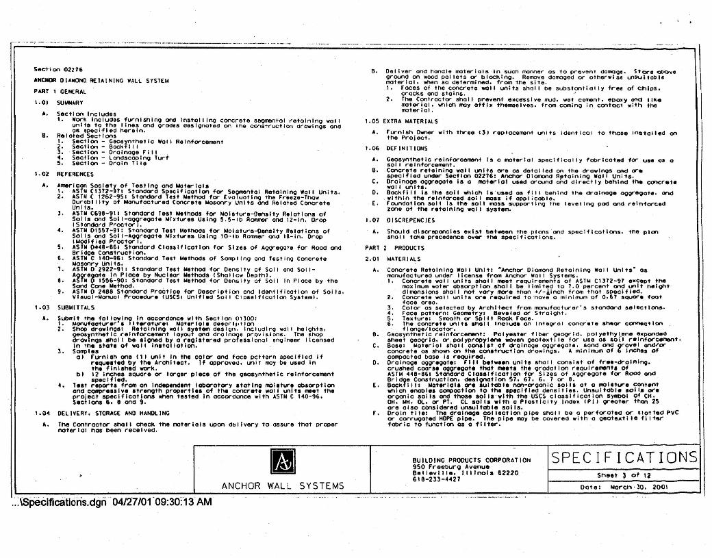
Section 02276ANCHOR DIAMOND RETAINING WALL SYSTEMPIIRT 1 GENERAL1.01
A.SUMM.t.RYSection InCludes1. work Includss furnlshlno and In5tailino concrete seomental retalnlno wal I
units to the lines and orades oeslonoted on the construction drawlnos andas specified herein.Re Ioted Sect Ions~: ~:~::~: g~:l7r7etlc Wall Reinforcement3. Seciion - Oralnooe F III .'4. Seciion - londscoplno Turf~. Section - Drain TI IeREfERENCES
B.
1.02
A. Amerlcon Society Of lestlno and NoterlalsI. ASlN CI372-911 Standard Specification for S.eomental Retalnlno Wall Units.2. .t.SlNC 1262-951 Standard Test Nethod for EvoluotlflQ the Freeze-Thaw
Ourobl IIty of Manufactured Concrete Masonry Units and Related ConcretelJnlts.l. IISTN C698-911 Standard T.st MethOds for Moisture-DenSity Relations of
Soils and Sol I-aooreoate Mlxtur.s Uslno S.S-Ib Rommer and 12-ln. OropIStandard Proctor"4. IoSTM 01557-91. Standard Test Methods for MOisture-Density Relations of
Soils ond Soll-Ioooreoale Mixtures Uslno IO-lb Rammer ond 18-ln. DropIMoo If led Proctor I.5. ASTM 0448-861 Standard Classification for Sizes of A9Qreoate for Rood andBrld08 Construction.6. ASTN C 140-961 Stondard Test Methods of Sompl InO and Testlno ConcreteMaSonry Unl ts.1. ASTM 0 2922-911 Standard Test Method for Density of Soil and Soll-
Aooreoote In Place by Nucleor Methods (Shallow Depthl.8. ASTM 0155£>-901 Standard Test Method for Density of Soil In Place by the
Sond Cone MethOd. .9. ASTM 0 24B8 Standard Practice for Description and Identification of Sol Is,Vleual-Monual Procedure (USeSI Unlfl.d Sol I Classification S~6t.ml.
SUBMITTALSSubmit the followlno In accordance with Section 01300:1. ManufOcture ••'. Iiteraturel Material. d•••crl"llon2. Shop drowlnoe: Retalnlno wall Iystem desll/f1. Including wall helohts.oeosynthetlc reinforcement layout and drolno08 provisions. The shop
drowinos aholl be Iloned by a reolstered professional anl/lneer licensedIn the state of wall Installation.
3. 50"1lle.01 rurnlsh one " I unit In the color and face pottern specifIed if
reque.ted by the Architect. If opprov80, unit may be used Inthl finished work.
b) 12 Inches sQUare or loroer ~Iece of the oeoeynthetlc reinforcementspeclfl.d. .
4. le.t reporta from on Indeplndlnt loboratory .totlno molltur. obaorptlonand compr ••• 've .treooth properties of the coneret. wall unit. meet theproject specifications When tested In accordance with ASTY C 140-'6.S.ctlons 6. 8 ond g.
DELIVERY. S10RAGE AND HANDLING
1.03•..
1.04A. The Contractor sholl check the materials upon dullvery to assure that proper
material haS been received.
SPECIFICATIONS•ANCHOR WALL SYSTEMS.·.-:~pecifications.dgn··04/27/01·09:30:-13 AM
B. Deliver and handle moterlolsln such monner as to prevent damooe. Store ~veoround on wOad pallets or bIOCklno. Reroove domooed or otherwise uns<JltOblematerial. when so determined. from the site.I. Faces of the concrete wall units sno i t De substantially iree of Ctllps.
crocks and stains. .>2. The Contractor sholl prevent e~cesslve mud. wet cement. epoxy ~ likematerial. which moy affix th.mselves. from cominQ In contact with themoter I01.
1.05 EXTRA MATERIALSFurnish Owner with three (31 replacement units identical to those Installed onthe ProJect.OEr INIT IONS
A.
1.06A.B.C.D.
.[,
1.01A.
PART 2
2.01II.
Geosynthetlc reinforcement Is a material specifically fODrlcated for u.e 05 0sol I r.lnforcement.Concrete retolnlno wall unite or. 06 d••talled on the drawinos and orespeclfl.d under Section 02216: Anchor Diamond Rptoinlno Wall Units.Orolno08 oooreoote Ie a material used oround and directly behind the concretewall unite.BOCkfl II Ie the soil which Ie used as fll I Dehlnd the drainooe OOor.90t., Ondwithin the reinforced soil mass If oppl t cob re,foundation 5011 Is the 5011 mass supportlno tne level InO pod and rel~forcedzone of the retalnlno wall system.OISCREP(NCIESShould discrepancies exist between the plonsond sp.cifications. the pIonShall to~e precedence over the specifications.
PRODUCTSMATER IALSConcrete Retalnlno Wall Unit: ·Anchor Diamond Retolnlno Wal I Units· asmanufactured under license from Anchor Wall Systems.I. Concrete wall units sholl meet· requirements of IISTM C,'72-97 e_Cept t~
maximum water absorption Sholl be Ilmlt~d to 1.0 percent and unit helQhtdimensions shall not vary more than +/-4InCh 'from that sP.clfled.
2. Concrete wall units ore require" to·no.e 0 minimum of 0.67 square footface area.3. Color as selected by Iorchltect from manufocturer's standard selections.4. Face pattern: Geometry. Bevel.d or StralOht.5. Texture. Smooth or Spilt Rock Face.6. The concrete units ahol I Include on Inteorol concrete sheor conn.ctlon
f Ionoe/ locator.Geosynthetlc reinforcement: Polyester fiber oe09rlO. poly.thy •..•ne ."ponGedsheet oe09r1d. or.pOlypropylen. woven oeotextl ie for use 06 60/.1 reinforcement.Bose: Material aholl consl.t of dralno08 oooreoote. sand ond orovel and/orconcrete as shown on the construction .orowlnos. A mlnlrrum of 6 lr1CheS ofcompacted base Is reQUired.Drolnaoe ooor.ootel Fill between units 5hal I consist of fr.e-drolnlno.crushed coor •• aooreoot. thOt me.t. the Oradatlon requirement. ofASTM 448-861 Standord Closelflcotlon for Sizes of "ooreoote for Rood andBrido. Construction. d.sloootion 51. 67. 6. 7 or 8.BOCkfl1 I: Noterlal. ore .ultoble non-orOonlc solll at 0 mol.tur. contentwhich enable. oompactlon to the specified densities. Unsuitable solie oreorOonlc 50115 and thase sollS'wlth the uses classification symbOl of CH.OH.IoIH. 01.. or PT. Cl eolls with a PlastiCity Index (P/l oreoter than 25ore 0150 cOnsidered unsultoble set rs.Droin ti Ie: The drolnooe collection pipe snct t be a perforated or Slotted PVCor corruooted HOPE pipe. The pipe may be covered with a oeotexti Ie il Iterfabric to function as 0 filter.
B.C.
D.
Eo
f.
BUILDING PRODUCTS CORPORATION950 Freeburo AvenueBellevl lie. III Inols 62220618-23:3-4427 Sheet ~ of 12
Oat,,: Morct ••·30, 2001

PART 3 EXECUT ION3.01 EXAMINATION
A. The contractor shol I e~omlne the areas and conditions under which the retainingwol I is to be erected and notify the. Architect or Civi I Engineer in writing ofconditions detrimental to the proper and timely completion of the work. Do notproceed wi th the work unt II unsat Isfactory cooo+ t Iens hove been corrected. Thecontractor sholl promptly notify the wol I design enolneer or any site conditionswhich mey affect wall performance or may require 0 reevoluotlon of the wal Ide819n.
3.02 EXCAVATIONA. The Contractor shOI I excavate to the lines and Qrades shown on the construction
drowinos. Over-excavation not approved by the owner or duly appointed owner'srepresentative shol I not be paid for and replacement with compacted fill and/orwall system components will be required at the Contractor's expense. TheContractor sholl be careful not to disturb base beyond the lines shown. TheContractor sholl be responsible for the .tability of the excavotlon and It'sInfluence on adjacent properties and structures.FOUNDATION PREPARATION3.03
A.e.
Foundation sol I sholl be excavated as required for footlno or bose dimensionshown on the construction drawings. or as directed by the Enolneer.Foundation sol I sholl be examined by the project geotechnical enOlneer toensure thot the actual foundation sol I strength meets or exceeds that requiredon the construction drawings. Soil not meetlno the required strength sholl beremoved. sufficiently oversized from the front of the block and the bock of thereinforcement and backfilled with suitable materlol. 'Over-excavated areas sholl be filled with suitable compacted backfill.BASE COURSE PREPARATION
C.3.0<4
A.8.C.D.E.
Bose materials shol I be placed as shOwn on the construction drawlnQs with aminimum thickness of 6 Inches.Bose materials shal I be Installed upon undisturbed soils. ar foundation sallsprepared In accordance with Section 3.03. .Waterlol sholl be compacted so as to provide a level. hard surface on which toplace the first coursa of units.Base materials shal I be prepared to ensure complete contact of retainlno wal Iunit. Gaps shal I not be allowed.Base materials shOl I be to the depths and widths shown on the plans. TheControctgr may apt for ullno reduced depth of sand and orovel and replacementwith a 1 to 2" concrete topplno. Cancrete shol I be leon. unrelnfarced and amaximum of two Inches thick. Whera a ralnforced footlno Is reQuired. plocebelow the frost Iina.
3.05A.S.
ERECTIONErect units as specified herein.,Ir.t cour.e of concrete wall unit •• holt be placed on the prepared basematerial. Units Sholl be checked for level and aiionment. The top of allunite In bo.e course sholl be at the lama elevation.Ensure that concrete wall unite ore In full conlact with base.Canerete wall unit •• hatl be placed Iide by side for full lenoth of wallollanman,. Allonment may be done by u.lng a strino line or offset of wall line,Fill all VOid. b.tween and within concrete wall units with dralnaoe oooreoate.A minimum of 12 Inch •• of dralnoo. ooor.oote ,hall be placed behind theooncrete .011 unit ••Drolntlle sholl be Installed at the lowast elevation possible to maintainoravlty flow of water to outside of th' reinforced zone. The dralnaoecollection pipe shOll be dayllonted to on appropriate location away from thewall system at each low point or at 50 foot Intervals oiono the wal I.Remove all excess fill from top of units and Instal I next course. EnsureOralnaoe oooreoote and backfll I ore compacted before Installation of next course •
C.D.E.,.G.
H.
•ANCHOR WALL SYSTEMS.-.-1Sj5eclf1cations.-a-gn-0472i70Ttl9:3"O:S-ffAM
....-~1
I.
J.
3.06A.8.
C.
D.
course, Backfl lias each course IS completed. Pullthe loootino surface of the unit contocts tne locotlngthe precedino course. Pull the units forword os for
Install each succeedlnothe uni ts forward unt iIsurface of the units Inas possible.~~~~~~t~~~~r~t~:~~~~~~~~:~~~In accordance with oeosynth8tlo
the design drowinos.BACH ILL PL ACEMENTReinforced backfill sholl be placed. spread and compacted in a manner that willminimize slack In the reinforcement.FII I In the reinforced zone .holl be placed and conpacted In 11ft. not toexceed G to 8 Inches (loose thickness) where,hond-OPerated compaction e~lpmentis used and not exceedln9 12 inches I loose thickness) where,heovy. self-prapel led compaction equIpment Is used.
All fill placed in the reinforced zone must be compacted to a minimum of 9;percent of the soil's standard Proctor denSity IASTM D 698-91) or asrecommended by the project geotechnical enoineer.Only IIQhtweight hand-operated eQUipment sholl be 01 lowed within ~ feet of thebock of the retolnlno wall units. or one-half of the wal I heioht. whiChever isgreater.
3.07A.8.C.
3.08
CAP UNIT INSTALLATION IIf AppllcablelApply construction adhesive to the tap surface of lhe unit below and place thecop unit Into desired position.Cop units may need to be cut to obtain the proper fit.Backfill and compact to finish orode.AOJUSTING AND CLEANING
A.B. Damooed units should be replaced with new units during construction.Contractor sholl remove debris caused by wol I construction and leave adjacentpaved areas broom cleon.Ouollty ControlThe wall Installation contractor Is responsible for Qual ity control ofInstallation of all moterlols. The contractor should enlist the assistanceof a Qualified Independent third party to verify the correct Instal lotionof all moterlals accordlno to these specifications and the constructiondrowlnos.The Owner. at his own e~pense. should retain a Qual ified professional toperform random Quality assurance cnecxs of the contractor's work.Work found to be deficient accordlno to these specificationS or theconstruction drawlnos must be corrected at the contractor's expense.The retaining wall will not be considered complete untl I e~cepted bY theenoineer or duly appOinted owner's representative.Measurement and PaymentMeasurement of seQmentOI retalnlhQ wall shal I be on an Installed square footbasis computed on the total face oreo of wal I installed. Wall foee areo Istoken from the bottom of the base course to the top of the wall.Payment for the wall will be mode en a square foot basis at the contract unitprice.I. Payment should be considered full compensat ion for all lobor. mat ••.•lals •
equipment and te.tlno required to instal I the wall in QCcordance withthese speclfloatlons ond the construction drawlnos.2. Ouontltle. may yary from that Ihown en the construction OrawinOI dePendlnoon elll.tlno tOPOQrOPhy. Chonoe to the total Quantity of wall foee oreowill be pard or withheld at the oontract unit bid price.
3.09A.
B.C.O.
3.10A.
B.
Dote: MorCh .30. 2001
SPECIFICATIONSBUILDING PRODUCTS CORPORATION950 Freeburg AvenueBe t lav t lie. Illinois 62220618-233-4427 Sheet ~ of 12
---~"'--"'" ....
I""·' .•........_-.... .-.. ....•-- •.------.- .•--- " ----.---.- .. -.--- - ..".
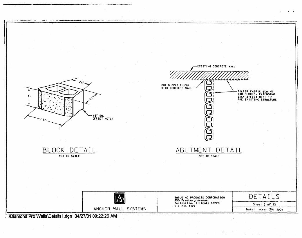
BLOCK DETAIL ABUTMENT DETAILNOT TO SCALE NOT TO SCALE
DETAILSSheet ~ of' 12
BUILDING PRODUCTS CORPORAl ION950 Freeburo AvenueBellevi IIe. Illinois 62220618-233-4427ANCHOR WALL SYSTEMS Dote: Morch·30. 2001
::":~OiamondPro Walls\Oetansf:dgn-()4/27fOT09:'2'2:1-ErAM--'~"--"-----.------------" ...---- ..----.--.--.-
.:lTypicarsections.dgn041T1T0109:36:41 AlV1-----------·-
Sheet f> o~ 12
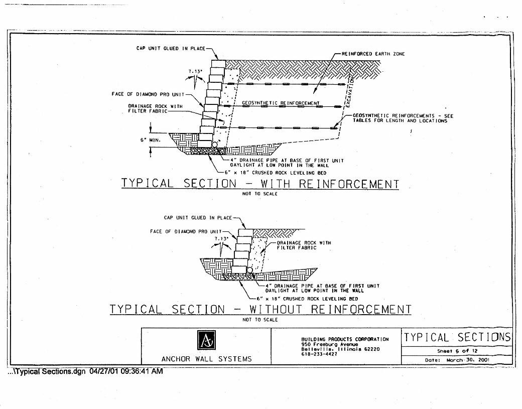
CAP UNIT GLUED IN PLACE
GEOSYNTHETIC REINFORCEMENTS - SEETABLES FOR LENGTH ANO LOCATIONS
FACE OF DIAMOND PRO UNIT
crt"'tLi! ••• !lJ: • ~ I •••• IiiiIiiiIIa.a!! ," •••••i ....•....'1 '1 'rsn=iiTTr=:m -------.J_ ..._ ••..Jr-rr !.U..-
.1I.....:
r--;'"-: I
GEOSYNTHETIC REINFORCEMENTDRAINAGE ROCK WITHFILTER FABRIC __
4U DRAINAGE PIPE AT BASE OF FIRST UNITDAYLICHT AT lOW POINT IN THE WALL
18" CRUSHED ROCK LEVELING BED
TYPICAL SECTION WITH REINFORCEMENTNOT TO SCALE
CAP UNIT GLUED IN PLACE
"U DRAINAGE PIPE AT BASE OF FIRST UNITDAYLIGHT AT LOW POINT IN THE WALL
6u x Ie" CRUSHED ROCK LEVELING BED
FACE OF
TYPICAL SECTION WITHOUT REINFORCEMENTNOT TO SCALE
ANCHOR WALL SYSTEMS
BUILDINC PRODUCTS CORPORATION950 Freeburo AvenueBelleville. IllinoiS 62220618-233-"427
[I] TYPICAL SECTIONSDote: March· 30. 2001

r-----------------
.~_:miamond Pro-waTfS';Oetails2.dgn O4lm01O~f3S:5"9 AM-- -----
Sheet 7 of 12
2M to )" OF SOIL FILL REOUIREO BETWEENOVERLAPPED REINFORC[~NT FOR PROPER SOILAND REINFORCEMENT INTERACTION
t-Z
W Wz.J ::1:00.. w_
Ut-u O::uz Ow- •.•. 0::a: z_0.. wO
0:
FACE OF WALL
GEOGRID PANELS
GEOGRID PANELS
PRINCIPLE:Rt~rDIF~£C110N
BE VELED UN ITSMINIMUM RADIUS2 FT. TO fACE
PLACE ADDITIONAL REINFORCEMENT ON THENEXT COURSE OF SEGMENTAL UNITSIMMEDIATELY ABOVE THE SPECIFIEDPLACEMENT ELEVATION IN A MANNER THATELIMINATES GAPS LEFT BY THE PREviOUSLAYER OF GEOSYNTHETIC AT THE SPECIFIEDREINFORCEMENT ELEVATION.
INSIDE CORNER DETAIL OUTSIDE CORNER DETAILNOT TO SCALE NOT TO SCALE
11 DETAILSANCHOR WALL SYSTEMS
BUILDING PRODUCTS CORPORATION950 Freeburo AvenueBel 'evil Ie. I I I Inols 62220618-233-4421
Dote: March' 30. 2001
r----.-----.
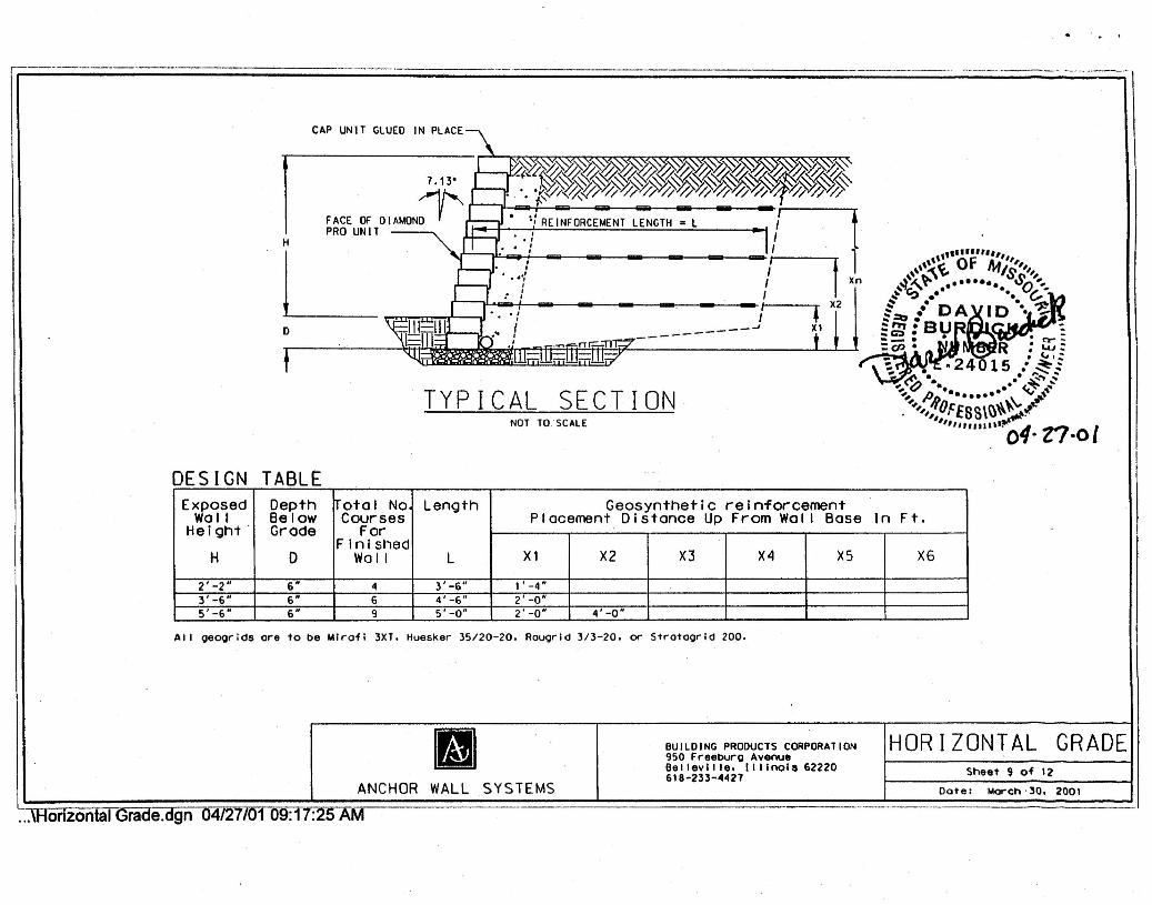
DESIGN TABL£Exposed Depth ~otal N°i Length I Geosynthetic reinforcementWall Below Courses Placement Distance Up From Wol I Base In Ft.Hel~ht . Grode For .
FinishedI I I I I IH 0 Wall L X1 X2 X3 X4 X5 X6
2'=-2" 6" 4 3' _6-il----I- 1 -, -4"
3'-6" 6" 6 4'-6" I 2'-0"5'-6" 6" 9 5'-0" I 2'-0" I 4'-0·
CAP UNIT GLUED IN PLACE\
'~~~~~%~~}~J}~J/'~~J}~J}~J}~J,"~Ji$J,%~'r'---.L!-t'"~,0<'~'~~'~'~\'~\'~'~'~'~'~':I'~'~</A7 .13" '\.»~~~~~~}~Y}~Y>~~Y>~J}~J}$l)t>,,»~%J,~'~ . '. 'f"'//0-.0 ~:I'/ ~ ~ ~ ~ ~ ~ ~:r/f :1'/~ ~
FACE OF DIAMOND " ~: REINFORCEMENT LENGTH = L I~.. .PRO UNIT '~ tL" !~'"
: f X2__ --oJ X1------o
tTYPICAL SECTION
NOT TO. SCALE
All oeoorids ore to be Mlroii 3XT. Huesker 35/20-20. Aougrld 3/3-20. or Strotoorid 200 .
• BUILDING PRODUCTS CORPORATION950 Freeburg AvenueBelleville. Illinois 62220618-233-4427ANCHOR WALL SYSTEMS
...\Horizontal Grade.dgn 047277011r9:T1:~5A"M
HORIZONTAL GRADESheet 9 of 12
Dote : Morch ,30. 2001

CAP UNIT GLUED IN PLACE
7.13'
~"J;;;:J'- ,-- - - - - -FACE OF DIAMOND r -._. If REINFORCEMENT LENGTH. LPRO UNITH
L~"'d." .~.C::J'-/ - - - - - - /f---
o __ -------.J
TYPICAL SECTIONNOT TO SCALE
DESIGN TABLEExposed Depth IrotaI No Length Geosynthetic reinforcementWall Below Courses Placement Distance Up From Wal I Bose In Ft.Height Grode ForF inished
H D Wall L Xl X2 X3 X4 X5 X62' -2" 6" 4 5'-0" 0' -8" 2'-0"3' _6N 6N 6 6' -0" l' -4 H 3' -4 H
5' -6" f>" 9 6' -0" 0' -8" 2'-0" 3' -4" 'I' -8 N
All oeOQrlds ore to be Mlrafl 3XT,Huesker 35/20-20. RauQrld 3/3-20. or Strataorld 200.
II BUILDING PRODUCTS CORPORATION950 Freeburo AvenueBelleville. Illinois 62220618-233-4427
HORIZONTAL GRADESheet '.0 of '2
ANCHOR WALL SYSTEMS Date: Morch·30. 2001
onzontal Grade.dgn 0412170n 2:43:11 PM

· .
CAP UNIT GLUED IN PLACE////I' /''''''~''''''',,''' ~I ". . .1 I
~" • , ENGT•• l I" r' · -I R".FORCE"'.T '~ IO
F DI"""O I '"FACE -- , IPRO UN'T I "
_I ~- - - ./ XI- . _J
q,.-.,- -------'.~: ---t t"i'!.!..l. I .ill. , .J
H
o
TYPICAL SECTIONNOT TO SCALE
DESIGN TABLE
". -• a::- .: •• ., •••• , : &.&.I:.:.-.~~ .1.4./"
'~~·.1:.'24015 ••ss.-~. . """' ..•• ~'.A • • . .;:"."0 ~-;o ,»; •• (.~--." A •••••••• v ••••
"",1fFE8S\\)"~~"'"111,,,, ••• 11" 0i·rr·()l
Exposed Depth ~ota I No Length Geosynthetlc reinforcementWall Below Courses Placement Distance Up From Wa II Base In Ft.He l crrt Grode ForFinished
H 0 WOII L X1 X2 X3 X4 X5 X6z' -2" 6' " 3' -6" l' -4"3 -6" 6" 6 " -6 o -8' 2 -85'-6~ 6H 9 6'-0" 0'-8" 2'-8" 4'-8"
All Qeoorids ore to be Mlrofi 3XT. Huesker 35/20-20. Rouorld 3/3-20. or Strataorld 200.
11 BUILDING PRODUCTS CORPORATION950 Freeburg AvenueBe llev llie. Illinois 62220618-233-4427ANCHOR WALL SYSTEMS
...\sloping"Grade.dgn·04727l0T12:4~[t6-?M
SLOPING GRADESheet 11 of 12
Dote: Moren.30. 2001
..-.-.~ .-. ~•.... -. -..---. - ........ - - .. ..",.- -.
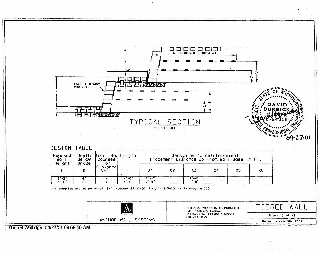
I iB .:IIEIIEIIElIEUEIIEIIEREINFORCEMENT LENGTH = L
IH .L-,/f>2H ,L,J • X4
IIIEol; ;111;:IUml Xlj~~gEu~~TDIAMOND ~PrnDOliE8lllE8nn
"", 1111
;:"""",H '8 f \\",:\~0 . lvi'S"'"L ,,~,. ••••••• SO''''~'C? ••• -. ~-:..L-,J • X2 t: l·DAVID·;ll~0 -=111=111:"":11-=1 I tJ :[g~,I;lICK-_. .,..~-, IEIILIII~I .cp. ", :L.u::. .. . ~:::-.TYPICAL SECTION ~ .. 2~hs.·~:::-.'
...•• ~.. ... ~~-;.. . ~ ~NOT TO SCALE ~, I'J. •••••••• ••••... '''',,10FE8S\\l\\~~'\\\I" ,lI,,,,,••"lloq .Z,7.01
DESIGN TABLE -
Exposed Depth Total No Length Geosynthetic reinforcementWall Below Courses Placement Distance Up From Wal I Bose In F t.Height Grode ForFinishedH D Wall L Xl X2 X3 X4 X5 X6
2' _2" 6" 4 ,;4' -0" l' -4" I' -4"3' -6" 6H 6 5' -0" 2'-0" 2.' -0"
All oeogrids ore to be Mirofl 3XT. Huesker 35/20-20. Raugrld 3/3-20. or Stratogrid 200.
m BUILDING PRODUCTS CORPORATION TIERED WALL950 Freeburg AvenueBelleville. Illinois 62220 Sheet ',2of 12618-233-4421ANCHOR WALL SYSTEMS Dote: Morch'30. 2001
.- - - .....ffieredWall.dgn 04/27/01 09:58:50 AM

6" MINIMUM CONPACTEOGRANULAR BASE
LEV.ELING PAD MADE FROMCRUSHED ROCK OR CONCRETEMINIMUM SIZE 6" x 18"
L6" MINIMUM ,,-,11 III-f
REINFORCEMENT LENGTHI •••10· MIN IMUM
PULL OUT SLACK IN REINFORCEMENT -
LEVELING PAD DETAIL CONNECTION DETAILNOT TO SCALE NOT TO SCALE
., :~Dlainon(rprO-Warrs\Oetafls3.dgn-04721IOT-09-:40~l:rAJliC-- ---------------
11 DElA ILSANCHOR WALL SYSTEMS
BUILDING PROOUCTS CORPORATION950 Freeburg AvenueBel lev; I Ie. Illinois 62220618-233-40421 Sheet ~ of 12
Dote: Morch·3D. 2001
Related Documents