Anatomic Fracture and Reverse Fracture Surgical Technique

Welcome message from author
This document is posted to help you gain knowledge. Please leave a comment to let me know what you think about it! Share it to your friends and learn new things together.
Transcript

Anatomic Fracture and Reverse FractureSurgical Technique

Table of Contents
Key Surgical Steps GLOBAL UNITE™ Platform Shoulder System Key Surgical Steps: Anatomic Fracture 4
GLOBAL UNITE Platform Shoulder System Key Surgical Steps: Reverse Fracture 6
Surgical Technique: Anatomic Fracture Soft Tissue Dissection 8
Humeral Preparation 9
Trial Implantation and Tuberosity Reduction: Press-Fit Fixation 12
Trial Implantation and Tuberosity Reduction: Cemented Fixation 16
Humeral Shaft Preparation for Tuberosity Fixation: Cemented and Press-Fit Fixation 19
Final Stem and Proximal Component Assembly and Implantation: Cemented Fixation and Press-Fit Fixation 20
Final Tuberosity Attachment 24
Quick Suture Guide: Anatomic Addendum 1 26
Conversion to DELTA XTEND™ Reverse Shoulder System 28
Surgical Technique: Reverse Fracture Tuberosity Management and Glenoid Preparation 34
Humeral Preparation 35
Trial Stem and Epiphysis Assembly and Implantation 36
Humeral Shaft Preparation 40
Final Stem and Epiphysis Assembly and Implantation 41
Suture Guide: Reverse Fracture 42
Alternative Suture Guide: Reverse Fracture Addendum 1 44
Key Information Instrument Ordering Information 46
Implant Ordering Information 51
Component Compatibility 53
Indications for Use 54
2 DePuy Synthes GLOBAL UNITE™ Platform Shoulder System Anatomic Fracture and Reverse Fracture Surgical Technique

Surgical Technique GLOBAL UNITE™ Platform Shoulder System Anatomic Fracture and Reverse Fracture DePuy Synthes 3
GLOBAL UNITE™ Fracture SystemSuture Attachment Features
Modular Suture Collar: Attachment site with multiple holes to allow for flexibility in reattachment of the tuberosities and rotator cuff to the prosthesis and proximal humeral shaft
Medial Suture Pass-Through Hole: Placement of an “Around the World” cerclage suture
Suture Collar: Attachment site with multiple holes to allow for flexibility in reattachment of the tuberosities and rotator cuff to the prosthesis and proximal humeral shaft
Suture Pockets: Attachment of the tuberosities to each other and to the prosthesis
Anterior-Posterior Suture Pass-Through Hole: Placement of an “Around the World” cerclage suture
Anatomic Fracture Proximal Body and Modular Suture Collar
Reverse Fracture Epiphysis
C
B B
B
C
B
A A
A
A

4 DePuy Synthes GLOBAL UNITE™ Platform Shoulder System Anatomic Fracture and Reverse Fracture Surgical Technique
Key Surgical Steps: Anatomic Fracture
Remove Humeral Head and Tag Tuberosities
Ream Humeral Canal Assemble Trial Components (0 Body)
Impact Collar Place Suture Through Collar and Impact Head
Press-Fit Fixation
Cemented Fixation
Insert Implant and Impact
Insert Implant with Jig
ANATOMIC FRACTURE

Surgical Technique GLOBAL UNITE™ Platform Shoulder System Anatomic Fracture and Reverse Fracture DePuy Synthes 5
Attach Trial Collar Component and Reduce Tuberosities
Create Final Construct
Suture Tuberosities Finished Tuberosity Reconstruction
Press-Fit Fixation
Cemented Fixation
Trial Insertion with Trial Inserter
Trial Insertion with Positioning Jig
ANATOMIC FRACTURE

6 DePuy Synthes GLOBAL UNITE™ Platform Shoulder System Anatomic Fracture and Reverse Fracture Surgical Technique
Key Surgical Steps: Reverse FractureREVERSE FRACTURE
Remove Humeral Head and Tag Tuberosities
Suture tuberosities
Ream Humeral Canal
Implant Insertion with the Humeral Implant Driver
Implant Insertion with the Fracture Jig
Assemble Trial Components
Assemble Final Construct
Press-Fit Fixation
Cemented Fixation

Surgical Technique GLOBAL UNITE™ Platform Shoulder System Anatomic Fracture and Reverse Fracture DePuy Synthes 7
REVERSE FRACTURE
Insert Final Humeral Cup Finish Tuberosity Reconstruction
Trial Insertion with the Humeral Implant Driver
Humeral Cup Trialing
Trial Insertion with the Fracture Jig Humeral Cup Trialing
Press-Fit Fixation
Cemented Fixation
Prepare the Humeral Shaft
Insert Final Humeral Cup Finish Tuberosity Reconstruction
8 DePuy Synthes GLOBAL UNITE™ Platform Shoulder System Anatomic Fracture and Reverse Fracture Surgical Technique
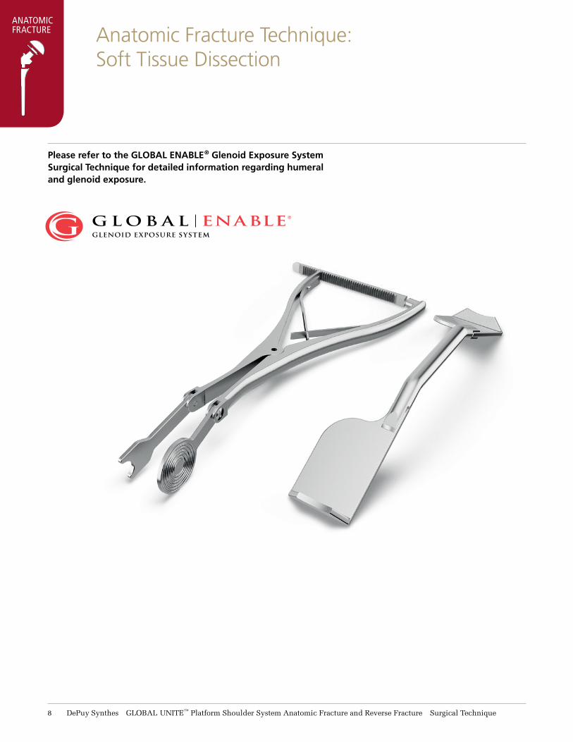
Anatomic Fracture Technique:Soft Tissue Dissection
ANATOMIC FRACTURE
Please refer to the GLOBAL ENABLE® Glenoid Exposure System Surgical Technique for detailed information regarding humeral and glenoid exposure.

Surgical Technique GLOBAL UNITE™ Platform Shoulder System Anatomic Fracture and Reverse Fracture DePuy Synthes 9
Humeral Preparation
Greater and Lesser Tuberosity Mobilization
Mobilize the greater and lesser tuberosities from adhesions and attached hematoma. Leave any capsule or healthy soft tissues attached to the proximal humerus. Pass sutures at the tendon bone interface as traction sutures. This step should result in normal mobility of these tissues (Figure 1).
With the greater and lesser tuberosities mobilized and retracted out of the way by the stay sutures, use a clamp to retrieve the fractured humeral head. Remove any portion of articular humeral head that may remain on the tuberosity fragments. Open the sheath of the biceps tendon and divide the transverse humeral ligament. Remove the long head of the biceps and tenodese it distally to local soft tissue and resect the proximal portion to the superior glenoid tubercle. After removal of the biceps tendon examine the glenoid fossa for fracture or arthritic changes that may need to be surgically treated.
Figure 1
Stay Suture 2
Stay Suture 1
ANATOMIC FRACTURE

11 DePuy Synthes GLOBAL UNITE™ Platform Shoulder System Anatomic Fracture and Reverse Fracture Surgical Technique
Figure 2
Removal and Assessment of the Head
The selected humeral head component should be approximately 3mm smaller in height than the resected humeral head because of the suture collar. The radius of curvature should be approximately the same. Assess the resected humeral head for height and diameter using the Humeral Head Template. The template takes into account the thickness of the prosthetic head and the suture collar; together these two components represent the volume of the native humeral head (Figure 2). Two styles of humeral head trials are available for the fracture set ranging from 12, 15, 18 and 21mm heights and 40, 44, 48, 52 and 56mm diameters.
After selecting the desired humeral head size, select the corresponding trial suture collar size. The selected head size and trial collar are color coded and should match (Figure 3).
Note: The diameter of the suture collar must never be larger than the diameter of the head.
Humeral PreparationANATOMIC FRACTURE
52 x 15mm Common Trial Humeral Head
52mm Trial Suture Collar
Figure 3

Surgical Technique GLOBAL UNITE™ Platform Shoulder System Anatomic Fracture and Reverse Fracture DePuy Synthes 11
Humeral Preparation
Cancellous Bone Removal
After selecting the humeral head component, place the humeral head on the back table to be used later if necessary as a source for cancellous bone graft.
Humeral Shaft Preparation
Place the arm in extension, adduction and external rotation. The arm and elbow should extend off the side of the table, which delivers the shaft out of the wound.
Starting with a 6mm reamer, sequentially ream the medullary canal to determine the humeral stem size (Figure 4). For press-fit fixation of standard length stems, ream to the largest size obtaining distal cortical contact such that the proximal edge of the cutting flutes reach the anatomic height of the detached greater tuberosity. For long stemmed implants, the reamers are advanced distally until the laser mark located superior on the reamer shaft reaches the same estimated level of the greater tuberosity. In some cases this will need to be estimated by approximating the greater tuberosity to the proximal part of the humeral shaft fracture line or the height of the greater tuberosity fragment(s) is determined with a ruler.
Figure 4
ANATOMIC FRACTURE

12 DePuy Synthes GLOBAL UNITE™ Platform Shoulder System Anatomic Fracture and Reverse Fracture Surgical Technique
ANATOMIC FRACTURE
Press-Fit Fixation
Figure 7
Retroversion Alignment
Figure 6
Figure 5
Trial Assembly and Positioning
Assemble the selected stem with the corresponding proximal body size 0 trial. The stem and proximal component are color coded. Utilize the female hex screwdriver (green handle) and distal stem wrench to connect the two components (Figure 5).
Restoring Proper Retroversion and Height
With the inserter, place the stem assembly into the intramedullary canal so that it is firmly fixed within the canal. The horseshoe collar of the stem inserter represents the final location of the suture collar and can be used as a reference to the medial calcar for the correct height placement (Figure 6). An alignment rod may be attached to the inserter at the desired retroversion. The alignment rod is inserted into the desired version hole on the inserter and is then aligned to the forearm (Figure 7). Native version varies within the normal population with an average retroversion of approximately 20 to 30 degrees with respect to the axis of the forearm when the elbow is in 90 degrees of flexion.
Trial Implantation and Tuberosity Reduction:

Surgical Technique GLOBAL UNITE™ Platform Shoulder System Anatomic Fracture and Reverse Fracture DePuy Synthes 13
ANATOMIC FRACTURE
Press-Fit Fixation Press-Fit Fixation
Trial Implantation and Tuberosity Reduction:
Assemble the trial collar onto the epiphysis and reduce the greater tuberosity. The desired height of the stem is achieved when the greater tuberosity (supraspinatus rotator cuff insertion) is located under the collar and the distal portion of the tuberosity is anatomically reduced to the humeral shaft.
If the stem is stable in the canal and the tuberosity is above the collar by 5mm or more, the stem is too low. Remove the 0mm proximal body component and attach the +5mm proximal component. If the trial collar is still
too low then trial a larger stem or use the positioning jig and utilize bone cement to place the originally selected stem at the desired height.
If the trial stem and collar are too high, then remove the 0mm proximal body and replace it with the -5mm proximal body component. Minor corrections of 1–2mm can be achieved by impacting the trial stem further into the humerus. If the trial collar is still too high, then down size the stem and use the positioning jig and cement the stem (Figure 8).
Figure 8
-5
-5 0 +5
-5 -50 0
+5
Stem Height Adjustment
Proximal Body Sizes

14 DePuy Synthes GLOBAL UNITE™ Platform Shoulder System Anatomic Fracture and Reverse Fracture Surgical Technique
ANATOMIC FRACTURE Trial Implantation and Tuberosity Reduction:
Figure 9
Trial Reduction of Tuberosities
After determining the correct implant sizing, height and version, reduce and hold the greater tuberosity in its anatomic position using the Greater Tuberosity Forceps provided in the instrument set (Figure 9).If the greater tuberosity is displaced away from the stem then remove some of the cancellous bone from the tuberosity.
If the tuberosity is close to the stem but is not aligned with the edge of the centered suture collar, replace it with an eccentric collar and rotate it to optimize the alignment of the edge of the suture collar and the cuff insertion on the greater tuberosity. This should not result in an overhang of the collar with either of the tuberosities. Overhang can result in compromise or injury to the rotator cuff. If an eccentric collar is used then an eccentric head is also needed and positioned in the same orientation as the collar.
Press-Fit Fixation

Surgical Technique GLOBAL UNITE™ Platform Shoulder System Anatomic Fracture and Reverse Fracture DePuy Synthes 15
ANATOMIC FRACTURETrial Implantation and Tuberosity Reduction:
Figure 10
Place the correct sized head (centered or eccentric) as determined by the sizing gauge onto the stem. Reduce the humeral head into the glenoid and bring the lesser tuberosity around the stem to check its position and tension (Figure 10). Check soft tissue tensioning by performing a gentle range of motion.
It is recommended to perform an intra-operative X-ray or fluoroscopic examination to verify final prosthetic height and tuberosity position. The trial heads are barium infused and illuminate brightly under fluoroscopy.
Note: There are no holes in the trial collar. Notches on the collar identify the hole locations of the final implant.
Press-Fit Fixation Press-Fit Fixation

16 DePuy Synthes GLOBAL UNITE™ Platform Shoulder System Anatomic Fracture and Reverse Fracture Surgical Technique
ANATOMIC FRACTURE
Trial Assembly and Positioning: Using a Positioning Jig
Assemble the chosen stem with the corresponding proximal body size 0 trial. The stem and proximal component are color coded. Utilize the female hex screwdriver (green handle) and distal stem wrench to connect the two components.
Insert the trial stem using the inserter. The horseshoe collar of the stem inserter represents the final location of the suture collar and can be used as a reference to the medial calcar for the correct height placement. Use the positioning jig to then hold the trial stem in the desired position.
Positioning Jig
Loosely attach the positioning jig around the humeral shaft approximately 2 – 3cm distal to the fracture on the shaft (Figure 11). Align and attach the fin clamp to the anterior fin of the trial prosthesis assuring that the letter L or R is facing up denoting the side being operated upon (Figure 12). Rotate the stem and it’s attached positioning jig around the humeral shaft so that the alignment rod of the jig is in line with the forearm resulting in 30 degree retroversion of the stem to the forearm. Once the trial prosthesis is at the proper height and version, secure the positioning jig to the proximal humerus by tightening the large anterior screw using the 3.5mm hex screwdriver (yellow handle) (Figure 13).
Trial Implantation and Tuberosity Reduction:
Cemented Fixation
Figure 11
Figure 12
Figure 13

Surgical Technique GLOBAL UNITE™ Platform Shoulder System Anatomic Fracture and Reverse Fracture DePuy Synthes 17
ANATOMIC FRACTURE
Cemented Fixation
Figure 14
Trial Implantation and Tuberosity Reduction:
Assemble the selected trial collar on the proximal body (Figure 14).
The positioning jig holds the trial implant securely to perform trial reduction and test the range of motion and stability. One of the most important advantages of the positioning jig is to allow for reduction of the tuberosities. It also allows for range of motion testing with the trial prosthesis in place without a press-fit stem. During range of motion testing, the trial implant should remain in the glenoid fossa and the head should not ride high in the glenoid.
Adjust the stem height by sliding the fin clamp up or down the vertical height gauge so that the greater tuberosity is located under the collar and is reduced to the humeral shaft. To do this, use Greater Tuberosity Forceps provided in the instrument set or a towel clip to hold the greater tuberosities reduced around the prosthesis (Figure 15).
Cemented Fixation
Figure 15

18 DePuy Synthes GLOBAL UNITE™ Platform Shoulder System Anatomic Fracture and Reverse Fracture Surgical Technique
If the greater tuberosity is displaced away from the stem, then remove some of the cancellous bone from the tuberosity.
If the tuberosity is close to the stem but is not aligned with the edge of the centered suture collar, replace it with an eccentric collar and rotate it to optimize the alignment of the edge of the suture collar and the cuff insertion on the greater tuberosity. This should not result in an overhang of the collar with either of the tuberosities. Overhang can result in compromise or injury to the rotator cuff. If an eccentric collar is used then an eccentric head is also needed and positioned in the same orientation as the collar.
Place the correct sized head (centered or eccentric) as measured by the sizing gauge onto the stem (Figure 16). Reduce the humeral head into the glenoid and bring the lesser tuberosity around the stem to check its position and tension. Check soft tissue tensioning by performing a gentle range of motion.
It is recommended to take an intra-operative X-ray or fluoroscopic examination to verify final prosthetic height and tuberosity position. The trial heads are barium infused and illuminate brightly under fluoroscopy.
Note: There are no holes in the trial collar. Notches on the collar identify the hole locations of the final implant.
Trial Implantation and Tuberosity Reduction:
Cemented Fixation
Figure 16
ANATOMIC FRACTURE

Surgical Technique GLOBAL UNITE™ Platform Shoulder System Anatomic Fracture and Reverse Fracture DePuy Synthes 19
Humeral Shaft Preparation for Tuberosity Fixation
Prior to removal of the stem for cemented or cementless technique note the position of the stem for version and height based upon bone landmarks on the proximal shaft. Mark the cortex with an electrocautery knife.
For the cemented technique, loosen the anterior fin clamp from the anterior fin of the implant and leave the positioning jig in place. Be sure to check that it is securely attached to the shaft. Remove the trial implant from the humerus (Figure 17).
Drill two suture holes through the anterior lateral portion of the shaft 2cm below the fracture line.
Drill two suture holes through the posterior lateral portion of the shaft 2cm below the fracture line.
Pass four strands of non-absorbable suture that meets the USP knot tensile requirements for the intended use through the newly created holes. Both the anterior and posterior set of holes will have two sets of suture passing from inside the canal to the outside in a mattress suture technique. These will be utilized later as vertical suture fixation of the tuberosities (Figure 18).
Cemented and Press-Fit Fixation
Figure 17
Figure 18
Jig in Fixed Position
ANATOMIC FRACTURE

21 DePuy Synthes GLOBAL UNITE™ Platform Shoulder System Anatomic Fracture and Reverse Fracture Surgical Technique
ANATOMIC FRACTURE Final Stem and Proximal Component
Assembly and Implantation
Cemented Fixation
Figure 19
Assemble the appropriate sized stem and proximal component with the female hex screwdriver (green handle) and the modular implant locking wrench (Figure 19).
Place the implant into the impaction stand and impact the suture collar onto the neck in the intended position with the words “Side Up” facing up. Pass suture through the superior two holes of the suture collar to be used to reattach the supraspinatus and another suture through the suture collar more posterior to be used through infraspinatus, teres minor.

Surgical Technique GLOBAL UNITE™ Platform Shoulder System Anatomic Fracture and Reverse Fracture DePuy Synthes 21
ANATOMIC FRACTUREFinal Stem and Proximal Component
Assembly and Implantation
Cemented Fixation
Figure 20
Two sutures are placed in the anterior portion of the collar for reattaching the lesser tuberosity. All sutures should be placed so that the loose ends are exiting the top portion of the collar creating a loop on the bottom side of the collar (Figure 20).
Place a suture or larger non-absorbable suture through the medial hole of the proximal component of the assemble stem. When all sutures have been passed through the suture collar and implant the humeral head can be impacted in the impaction stand or later when the stem has been implanted.
Thoroughly irrigate the medullary canal to remove blood and other debris and dry the canal.
Insert a cement restrictor distally to the final implant location to prevent migration of cement distally towards elbow.

22 DePuy Synthes GLOBAL UNITE™ Platform Shoulder System Anatomic Fracture and Reverse Fracture Surgical Technique
ANATOMIC FRACTURE
Digitally insert bone cement into the medullary canal. If a cement gun is used, fill the canal from distal to proximal and avoid pressurization that could fracture the humeral shaft.
Insert the assembled final component into the cement to the height determined during the trialing process and hold in place via the positioning jig. With the positioning jig still in its original position secure the clamp to the anterior fin of the prosthesis to ensure that the final prosthetic is in the same position as the trial (Figure 21).
Before the bone cement hardens, remove the excess to a level just below the proximal body portion of the stem. This will allow placement of cancellous bone material as well as easy exchange of the proximal body component if the stem height needs to be adjusted using the 0 or +5 component. In addition, not cementing the proximal body component will aid in the removal of this part of the stem in the event of revision surgery for conversion to a reverse total shoulder.
Figure 21
Final Stem and Proximal ComponentAssembly and Implantation
Cemented Fixation

Surgical Technique GLOBAL UNITE™ Platform Shoulder System Anatomic Fracture and Reverse Fracture DePuy Synthes 23
ANATOMIC FRACTUREFinal Stem and Proximal Component
Assembly and Implantation
Press-Fit FixationAssemble the appropriate sized stem and proximal body component with the female hex screwdriver (green handle) and the modular implant locking wrench (Figure 22).
Place the implant into the impaction stand and impact the suture collar onto the neck in the intended position with the words “Side Up” facing up. Pass suture through the superior two holes of the suture collar to be used to reattach the supraspinatus and second set of suture through the suture collar more posterior to be used through infraspinatus and teres minor. Two sutures are placed in the anterior portion of the collar for reattaching the lesser tuberosity. All sutures should be placed so that the loose ends are exiting the top portion of the collar creating a loop on the bottom side of the collar (Figure 23).
Place a suture or larger non-absorbable suture through the medial hole of the proximal body component of the assemble stem.
When all sutures have been passed through the suture collar and implant the humeral head can be impacted in the impaction stand or later when the stem has been implanted.
Implant the final construct into the Humerus with the implant holder. Utilize the orientation pin placed into the proper alignment hole on the implant holder to assure that the implant is in the proper retroversion and impact the implant down to the proper height.
Figure 23
Figure 22

24 DePuy Synthes GLOBAL UNITE™ Platform Shoulder System Anatomic Fracture and Reverse Fracture Surgical Technique
ANATOMIC FRACTURE
Figure 24B
1
F D
G E
2
C
Medial/Proximal Body Suture
Final Tuberosity Attachment
Reattaching the Greater and Lesser Tuberosities to Suture Collar
Pass the suture of the medial stem hole through the cuff insertion on the greater tuberosity from inside out, and one through the insertion point of the subscapularis also in an inside to out fashion (suture 1 & 2 of Figure 24). These two ends are clamped and tied later.
Take posterior suture (E of Figure 25) in the collar and place it through the insertion of the infraspinatus from inside to out fashion. It is important to place the needle very close to the bone tendon junction.
The superior suture (D of Figure 25) for the supraspinatus is placed from inside to out in the same fashion. Tie the superior suture first and then the posterior suture. Do not cut off the ends of the suture after tying. These sutures will be used for the vertical tension band repair.
If the head has not been impacted, do so now with the head impactor.
The two anterior sutures are placed through the subscapularis tendon from an inside to out fashion close to the bone-tendon junction (F & G of Figure 25).

Surgical Technique GLOBAL UNITE™ Platform Shoulder System Anatomic Fracture and Reverse Fracture DePuy Synthes 25
ANATOMIC FRACTURE
Figure 25 Figure 26
B
B
1 1
F
F
D
D
G
G
E
E
2 2
C
C
Final Tuberosity Attachment
To assure proper placement of the sutures a trial reduction should be performed and verified via fluoroscopy. Once verification has been achieved the sutures can be tied.
The tuberosities are now attached to the suture collar. The loose ends of the two greater tuberosity sutures are tied to the lateral sutures in the humeral shaft in a vertical figure eight fashion (D & E to C, Figure 26).
This step will reduce the greater tuberosity into an anatomic position. The same process is performed with the sutures through the subscapularis (G & F to B, Figure 26) to create an anatomic reduction of the lesser tuberosity. These eight strands of suture create a tension band fixation of the tuberosities.
The final step is to tie the horizontal sutures running through the medial hole of the implant (1 & 2) in a cerclage fashion to provide addition strength/stability to the tuberosity fixation.

26 DePuy Synthes GLOBAL UNITE™ Platform Shoulder System Anatomic Fracture and Reverse Fracture Surgical Technique
ANATOMIC FRACTURE Quick Suture Guide: Anatomic Addendum 1
Drill four holes in humerus Pass suture from inside humerus to outside
Pass one leg of the suture down underneath the suture loop and tension it upwards
Pass leg of suture back inside humerus creating suture loop on exterior of humerus
Tie the suture to the other mating limb of the suture
Pass suture from the medial hole of the implant through greater and lesser tuberosity at the bone/tendon interface
1 2
7
9 10
3

Surgical Technique GLOBAL UNITE™ Platform Shoulder System Anatomic Fracture and Reverse Fracture DePuy Synthes 27
ANATOMIC FRACTUREQuick Suture Guide: Anatomic Addendum 1
Impact collar onto stem and pass suture through medial hole of implant
Pass the legs of the distal shaft suture up through the suture collar and from inside to outside through the tuberosity at the bone/tendon interface
Repeat the process with the remaining suture from the distal shaft
Please note the previously described suturing techniques are two methods of anatomically repairing the tuberosities. It is understood that additional methods can be utilized that incorporate the use of the suture holes in vertical and horizontal repair of the tuberosities. Variations of this technique can be modified to better suit a surgeon's preference.
Finalize the repair by tying the horizontal suture from the medial hole of the implant
Repeat the process two additional times creating three suture loops on exterior of humerus
Repeat the process with the remaining limbs of the suture to complete the vertical
repair of the tuberosities
Insert stem into the humerus at the proper height
11 12
8
4 5 6

28 DePuy Synthes GLOBAL UNITE™ Platform Shoulder System Anatomic Fracture and Reverse Fracture Surgical Technique
Conversion to DELTA XTEND™ Reverse Shoulder
Removing the Humeral Head and Proximal Component
Remove the head and suture collar using the head distractor.
Remove each component (head, collar) independently from each other starting by removing the head first and then followed by the suture collar.
Angle the head distractor so that both fingers of the instrument engage the collar (humeral head removal) or the proximal component (collar). This is important to assure that the appropriate mechanical forces are generated to remove the head and collar (Figure 27).
Figure 27
ANATOMIC FRACTURE CONVERSION TO REVERSE

Surgical Technique GLOBAL UNITE™ Platform Shoulder System Anatomic Fracture and Reverse Fracture DePuy Synthes 29
Conversion to DELTA XTEND Reverse Shoulder
Removing the Proximal Component
Use an appropriately sized thin osteotome from the DePuy Synthes Shoulder Extraction Instrument Set to remove the bone on-growth surrounding the proximal body.
Once the fixation between bone and proximal component has been broken, utilize the female hex screwdriver (green handle) to unscrew the proximal bolt (Figure 28).
Grasp proximal component with rongeur or similar device and remove it from the distal stem.
Figure 28
ANATOMIC FRACTURE
CONVERSION TO REVERSE

31 DePuy Synthes GLOBAL UNITE™ Platform Shoulder System Anatomic Fracture and Reverse Fracture Surgical Technique
Conversion to DELTA XTEND Reverse Shoulder
Humeral Reaming
Insert the orientation guide pin through the reaming guide at the desired epiphysis version. Place the assembled Epiphyseal Reaming Guide and orientation guide pin on the stem by aligning the guide pin to the forearm while keeping the reaming guide on the stem spigot (Figure 29).
Tighten the reaming guide screw to the stem using the 3.5mm Male Hex Screwdriver. Place the Sizing Guides onto the reaming guide in order to determine the correct reverse epiphysis size. The correct size will be contained within the cortical wall (Figure 30).
As a reference, the version holes superior to the center 0 degree groove are for a left shoulder, with each hole increasing retroversion by 10 degrees. The holes inferior to the center groove correlate to a right shoulder.
Note: The GLOBAL UNITE™ Reverse Fracture Epiphysis is only intended for use in the treatment of proximal humeral fractures. Bone preparation instrumentation has not been developed to accommodate its use in a non-fracture press-fit application. Press-fitting the GLOBAL UNITE Reverse Fracture Epiphysis in a non-fracture setting may result in a proximal humeral fracture.
Figure 29
Figure 30
ANATOMIC FRACTURE CONVERSION TO REVERSE

Surgical Technique GLOBAL UNITE™ Platform Shoulder System Anatomic Fracture and Reverse Fracture DePuy Synthes 31
Figure 32
Conversion to DELTA XTEND Reverse Shoulder
Select the color coded reamer (Red or Green) determined during the sizing exercise and prepare the humeral canal by using power (Figure 31). Once the reaming process has been completed the reamer guide can be removed utilizing the 3.5mm hex screwdriver (yellow handle).
Utilize an osteotome or rongeurs to remove any bone that may remain around the proximal portion of the distal stem that may prevent the proximal component from completely engaging with the stem (Figure 32).
Figure 31
ANATOMIC FRACTURE
CONVERSION TO REVERSE

32 DePuy Synthes GLOBAL UNITE™ Platform Shoulder System Anatomic Fracture and Reverse Fracture Surgical Technique
Conversion to DELTA XTEND Reverse Shoulder
Attaching the Trial Epiphysis Component to Distal Stem
Attach the DELTA XTEND™ Reverse Shoulder System Trial Epiphysis to the reverse epiphysis holder by squeezing the distal portion and placing it within the epiphysis. Align the pins on the outside of the epiphyseal holder with the notches on the implant and release the holder, this will lock the two components together (Figure 33).
Place the orientation guide pin through the retroversion hole that was originally determined during the reaming process (Figure 34). Align the trial epiphysis to the stem and align the pin to the forearm.
Figure 33
Figure 34
ANATOMIC FRACTURE CONVERSION TO REVERSE

Surgical Technique GLOBAL UNITE™ Platform Shoulder System Anatomic Fracture and Reverse Fracture DePuy Synthes 33
Figure 35
Conversion to DELTA XTEND Reverse Shoulder
Once the component is in proper orientation, place the 3.5mm hex screwdriver (yellow handle) through the inner portion of the proximal holder and securely tighten the bolt. Remove the reverse epiphyseal holder when this step has been completed (Figure 35). Remove any bone on the superior aspect of the trial epiphysis that could cause impingement. This can be done with an oscillating saw and using the trial epiphysis as a guide.
Please refer to GLOBAL UNITE Platform Shoulder System Anatomic and Reverse Shoulder Surgical Technique for the remaining steps of the procedure.
ANATOMIC FRACTURE
CONVERSION TO REVERSE

34 DePuy Synthes GLOBAL UNITE™ Platform Shoulder System Anatomic Fracture and Reverse Fracture Surgical Technique
Reverse Fracture Technique: Tuberosity Management and Glenoid Preparation
Tuberosity Management
The humeral head should be removed in its entirety making sure that no bone containing cartilage is left on the tuberosities. If there are any remnants of cartilage on the tuberosities, they can be removed with a rongeur. Management of the tuberosities is enhanced by passing stay sutures through the rotator cuff adjacent to the tuberosities. This will allow control of the fragments while preventing damage to the tuberosities themselves (Figure 36).
DELTA XTEND Reverse Shoulder System Glenoid Preparation and Implantation
Exposure to the glenoid is achieved and glenoid preparation is commenced. The glenoid is prepared as described in the technique for the DePuy Synthes GLOBAL UNITE Anatomic and Reverse Surgical Technique through the trial glenosphere phase.
Figure 36
Stay Suture 2
Stay Suture 1
REVERSE FRACTURE

Surgical Technique GLOBAL UNITE™ Platform Shoulder System Anatomic Fracture and Reverse Fracture DePuy Synthes 35
Humeral PreparationREVERSE
FRACTURE
Humeral Reaming
Once the glenoid preparation has been completed, the humeral shaft is exposed.
Starting with a 6mm reamer, sequentially ream the medullary canal to determine the humeral stem size (Figure 37). It is important to stop reaming once cortical contact is reached.
Figure 37

36 DePuy Synthes GLOBAL UNITE™ Platform Shoulder System Anatomic Fracture and Reverse Fracture Surgical Technique
Trial Stem and EpiphysisAssembly and Implantation
REVERSE FRACTURE
Trial Assembly
Assemble the desired GLOBAL UNITE Reverse Fracture Epiphysis Trial to the appropriate GLOBAL UNITE Stem Trial. The version of the Reverse Fracture Epiphysis is relative to the version the humeral stem will be placed. For example, if the GLOBAL UNITE Stem is placed in 30 degrees of retroversion relative to the humerus, and the Reverse Fracture Epiphysis is to be in 10 degrees of retroversion, the Reverse Fracture Epiphysis is set at 20 degrees of retroversion relative to the GLOBAL UNITE Humeral Stem (Figure 38). This allows for improved placement of the humeral stem while allowing appropriate positioning of the Reverse Fracture Epiphysis for a traditional reverse total shoulder arthroplasty. Utilize the male screwdriver (yellow handle) and the distal stem wrench to connect the two components (Figure 39).
Trial Insertion
Attach the assembled trial to the humeral implant driver and impact so that it is firmly fixed within the canal (Figure 40). An alignment rod may be attached to the inserter at the desired retroversion. The alignment rod is inserted into the desired version hole on the inserter and is then aligned to the forearm.
Note: There are no holes in the trial collar.Notches on the collar identify the hole locations of the final implant.
Figure 39
Figure 40
Left Shoulder
Anteversion
Retroversion
Retroversion
Anteversion
Right Shoulder
30°20°10°0°10°20°30°
30°20°10°0°10°20°30°
Figure 38

Surgical Technique GLOBAL UNITE™ Platform Shoulder System Anatomic Fracture and Reverse Fracture DePuy Synthes 37
Trial Stem and EpiphysisAssembly and Implantation
REVERSE FRACTURE
Determine Fixation Method
At this point, one needs to determine whether to use a press-fit or cement fixation technique. If it is possible to maintain correct height and rotational stability without use of the fracture jig, it is possible to implant the humeral component with a press-fit technique (Figure 41). The surgeon can also confirm that the tuberosities can be reduced to the desired height along the suture collar.
If necessary, excess bone may be removed from the tuberosities to optimize the reduction around the Reverse Fracture Epiphysis. If it is possible to achieve height and rotation control, soft tissue balancing can then be achieved by using thicker polyethylene inserts or combining this with the +9mm humeral spacer.
If adequate fixation is not achieved, a cemented technique should be utilized. The cemented technique will be described later on page 38.
Humeral Cup Trialing
If press-fit fixation is the chosen pathway, the surgeon can now begin trialing. Select the desired trial humeral cup and assess the prosthesis (Figure 42). Determining the proper height of the humeral component is one of the most crucial aspects of the case. Range of motion should be checked to make sure there is not excessive tension or laxity.
Once trialing is complete, the final glenosphere is now implanted per the GLOBAL UNITE Platform Shoulder System Anatomic and Reverse Shoulder Surgical Technique.
Proceed to the suture technique described on page 42.
Determine Fixation Method and Press-Fit Technique
Figure 41
Figure 42

38 DePuy Synthes GLOBAL UNITE™ Platform Shoulder System Anatomic Fracture and Reverse Fracture Surgical Technique
Trial Stem and EpiphysisAssembly and Implantation
REVERSE FRACTURE
Cemented FixationCemented Fracture Jig Attachment
If press-fit fixation is not desired, the surgeon may utilize the GLOBAL UNITE Fracture Jig (2100-01-036) to set the trial height and version.
The fracture jig can be attached to the anterior humeral shaft to allow better length and rotational control during trialing and placement of final humeral stem. The jig is placed approximately 2–3 cm distal to the level of the fracture. Occasionally, it is necessary to make a small opening in the latissimus tendon insertion to allow placement of the anterior arm of the jig.
Cemented Fracture Jig Assembly
The humeral trial, assembled previously, is attached to the fracture jig (Figure 43). The arm of the fracture jig is attached to the anterior pocket hole of the Reverse Fracture Epiphysis. Then slide the construct over the shaft of the fracture jig already in place and secure.
The version of the Reverse Fracture Epiphysis can be changed based on surgeon preference. The version can be verified by placing a guide pin through the proper hole on the humeral implant driver and aligning it with the forearm.
Figure 43

Surgical Technique GLOBAL UNITE™ Platform Shoulder System Anatomic Fracture and Reverse Fracture DePuy Synthes 39
Trial Stem and EpiphysisAssembly and Implantation
REVERSE FRACTURE
Cemented FixationCemented – Determining Humeral Height
Select the desired trial humeral cup and assess the prosthesis. Determining the proper height of the humeral component is one of the most crucial aspects of the case. The fracture jig or trial cup height can be adjusted for improved implant positioning and joint tensioning. Range of motion should be checked to make sure there is not excessive tension or laxity (Figure 44).
Once trialing is complete, remove the trial and leave the jig in place. The final glenosphere is now implanted per the GLOBAL UNITE Platform Shoulder System Anatomic and Reverse Shoulder Surgical Technique Guide.
Note: There are no holes in the trial collar. Notches on the collar identify the hole locations of the final implant.
Figure 44

41 DePuy Synthes GLOBAL UNITE™ Platform Shoulder System Anatomic Fracture and Reverse Fracture Surgical Technique
Humeral Shaft PreparationREVERSE FRACTURE
Humeral Shaft Preparation
A 2mm drill bit is used to drill holes in the proximal humeral shaft. Drill two suture holes through the anterior lateral portion of the shaft 2cm below the fracture line. Drill two suture holes through the posterior lateral portion of the shaft 2cm below the fracture line (Figure 45).
Follow steps 1 – 4 of the suturing technique to place the humeral shaft sutures on pages 42-43.
Figure 45

Surgical Technique GLOBAL UNITE™ Platform Shoulder System Anatomic Fracture and Reverse Fracture DePuy Synthes 41
Final Stem and EpiphysisAssembly and Implantation
Humeral Shaft PreparationREVERSE
FRACTURE
Implantation
Once the shaft sutures have been placed, the final humeral component is assembled and attached to the humeral implant driver.
If a press-fit technique is used, impact the construct into the humerus at the previously determined version. Confirm that the implant maintains height and rotation control (Figure 46).
If a cemented technique is used, the arm of the fracture jig is attached to the anterior pocket hole of the Reverse Fracture Epiphysis Implant. Insert bone cement into the medullary canal per the surgeon’s preferred method. Place the assembled final component into the cement to the height determined during the trialing process and hold in place via the fracture jig (Figure 47). Ensure the implant is in the same position as previously trialed. Before the bone cement hardens, remove the excess to a level just below the proximal body portion of the stem.
The fracture jig is then removed. Figure 46
Figure 47

42 DePuy Synthes GLOBAL UNITE™ Platform Shoulder System Anatomic Fracture and Reverse Fracture Surgical Technique
REVERSE FRACTURE Suture Guide: Reverse Fracture
Drill four holes in humerus Pass suture from inside humerus to outside
Pass suture through suture pocket holes Pass suture from the medial hole of the implant through the greater and lesser tuberosities at the bone/tendon interface
Pass leg of suture back inside humerus creating suture loop on exterior of humerus
With the construct reduced, tension and tie pocket suture bringing the greater and lesser
tuberosities together
Pass one leg of the suture down underneath the suture loop and tension it upwards
Tie the suture to the other mating limb of the suture
1
7
12 13 14
8
2 3

Surgical Technique GLOBAL UNITE™ Platform Shoulder System Anatomic Fracture and Reverse Fracture DePuy Synthes 43
REVERSE FRACTURE
Drill hole in the greater and lesser tuberosities
Pass the leg of the distal shaft suture up through the suture collar from inside to outside through the tuberosity at the bone/tendon interface
Repeat the process with the remaining sutures from the distal shaft
Pass leg of suture from the suture pockets through the pre-drilled hole of both the
greater and lesser tuberosities
Retrial the humerus and assess the prosthesis
Proceed with implanting the final polyethylene cup and reduce the humerus
Repeat the process two additional times creating three suture loops on exterior of humerus
Pass suture through medial hole of the reverse fracture epiphysis and insert the construct into
the humerus at the proper height
Repeat the process with the remaining limbs of the sutures to complete the vertical
repair of the tuberosities
Finalize the repair by tying the horizontal suture from the medial hole of the implant
11
15 16
9 10
4 5 6
Please note the previously described suturing technique is one method of anatomically repairing the tuberosities. It is understood that additional methods can be utilized that incorporate the use of the suture holes in vertical and horizontal repair of the tuberosities. Variations of this technique can be modified to better suit a surgeon's preference.

44 DePuy Synthes GLOBAL UNITE™ Platform Shoulder System Anatomic Fracture and Reverse Fracture Surgical Technique
Alternative Suture Guide: Reverse Fracture Addendum 1
Drill four holes in humerus Pass suture from outside humerus to inside Pass suture back outside humerus again
Pass suture through medial hole of the reverse fracture epiphysis Pass suture from the medial hole of the implant through the greater and lesser tuberosities at the bone/tendon interface
The tuberosities are now attached to the suture collar
The loose ends of the two greater tuberosity sutures are tied to the lateral sutures in the humeral shaft in a vertical figure of
eight fashion
REVERSE FRACTURE
The same process is performed with the sutures through the subscapularis to create an
anatomic reduction of the lesser tuberosity
1
7
12 13 14
8
2 3

Surgical Technique GLOBAL UNITE™ Platform Shoulder System Anatomic Fracture and Reverse Fracture DePuy Synthes 45
Pass sutures through suture collar creating loops. Insert the construct into the humerus
at the proper height
Pass suture through suture pocket holes
Pass legs of sutures from the suture collar and the suture pocket holes through the pre-drilled hole of both the greater and lesser tuberosities
Retrial the humerus and assess the prosthesis
Creating suture loop on interior of humerus Repeat the process once more creating two suture loops on interior of the humerus
REVERSE FRACTURE
These eight strands of suture create a tension band fixation of the tuberosities
Finalize the repair by tying the horizontal suture from the medial hole of the implant
11
15 16
9 10
4 5 6
Please note the previously described suturing technique is one method of anatomically repairing the tuberosities. It is understood that additional methods can be utilized that incorporate the use of the suture holes in vertical and horizontal repair of the tuberosities. Variations of this technique can be modified to better suit a surgeon's preference.

46 DePuy Synthes GLOBAL UNITE™ Platform Shoulder System Anatomic Fracture and Reverse Fracture Surgical Technique
Instrument Ordering Information Common Case
Top Tray — Humeral Preparation
2128-11-006 Bullet Tip Reamer 6mm
2128-11-007 Bullet Tip Reamer 7mm
2128-11-008 Bullet Tip Reamer 8mm
2128-11-009 Bullet Tip Reamer 9mm
2128-11-010 Bullet Tip Reamer 10mm
2128-11-011 Bullet Tip Reamer 11mm
2128-11-012 Bullet Tip Reamer 12mm
2128-11-013 Bullet Tip Reamer 13mm
2128-11-014 Bullet Tip Reamer 14mm
2128-11-015 Bullet Tip Reamer 15mm
2128-11-016 Bullet Tip Reamer 16mm
2128-61-070 Ratchet T-Handle
2307-84-003 Stem Wrench 6–8mm
2307-84-001 Stem Wrench 10–12mm
2307-84-002 Stem Wrench 14–16mm
2100-06-100 Humeral Stem 6mm Trial
2100-08-100 Humeral Stem 8mm Trial
2100-10-100 Humeral Stem 10mm Trial
2100-12-100 Humeral Stem 12mm Trial
2100-14-100 Humeral Stem 14mm Trial
2100-16-100 Humeral Stem 16mm Trial

Surgical Technique GLOBAL UNITE™ Platform Shoulder System Anatomic Fracture and Reverse Fracture DePuy Synthes 47
Instrument Ordering InformationCommon Case
Bottom Tray — Trial Heads
2130-20-000 3.2mm Osteotomy Guide Pin – Long
2100-70-155 4.0mm Female Hex Screwdriver
2100-70-150 3.5mm Hex Screwdriver
2001-65-000 Humeral Head Impactor
2100-01-022 Impaction Stand
2100-11-400 Common Humeral Head 40 X 12 Trial
2100-11-401 Common Humeral Head 40 X 15 Trial
2100-11-402 Common Humeral Head 40 X 18 Trial
2100-11-440 Common Humeral Head 44 X 12 Trial
2100-11-441 Common Humeral Head 44 X 15 Trial
2100-11-442 Common Humeral Head 44 X 18 Trial
2100-11-443 Common Humeral Head 44 X 21 Trial
2100-11-481 Common Humeral Head 48 X 15 Trial
2100-11-482 Common Humeral Head 48 X 18 Trial
2100-11-483 Common Humeral Head 48 X 21 Trial
2100-11-521 Common Humeral Head 52 X 15 Trial
2100-11-522 Common Humeral Head 52 X 18 Trial
2100-11-523 Common Humeral Head 52 X 21 Trial
2100-11-562 Common Humeral Head 56 X 18 Trial
2100-11-563 Common Humeral Head 56 X 21 Trial
2100-22-401 Common Humeral Head 40 X 15 Eccentric Trial
2100-22-402 Common Humeral Head 40 X 18 Eccentric Trial
2100-22-441 Common Humeral Head 44 X 15 Eccentric Trial
2100-22-442 Common Humeral Head 44 X 18 Eccentric Trial
2100-22-443 Common Humeral Head 44 X 21 Eccentric Trial
2100-22-481 Common Humeral Head 48 X 15 Eccentric Trial
2100-22-482 Common Humeral Head 48 X 18 Eccentric Trial
2100-22-483 Common Humeral Head 48 X 21 Eccentric Trial
2100-22-521 Common Humeral Head 52 X 15 Eccentric Trial
2100-22-522 Common Humeral Head 52 X 18 Eccentric Trial
2100-22-523 Common Humeral Head 52 X 21 Eccentric Trial
2100-22-562 Common Humeral Head 56 X 18 Eccentric Trial
2100-22-563 Common Humeral Head 56 X 21 Eccentric Trial

48 DePuy Synthes GLOBAL UNITE™ Platform Shoulder System Anatomic Fracture and Reverse Fracture Surgical Technique
Instrument Ordering Information Reverse Case
Humeral Tray 1
2100-74-006 Proximal Reaming Guide 6mm
2307-74-008 Proximal Reaming Guide 8mm
2307-74-010 Proximal Reaming Guide 10mm
2307-74-012 Proximal Reaming Guide 12mm
2307-74-014 Proximal Reaming Guide 14mm
2307-74-016 Proximal Reaming Guide 16mm
2307-74-001 Proximal Reaming Guide Holder
2307-74-002 Proximal Reaming Guide Holder Internal Rod
2307-76-001 Eccentric Proximal Reaming Adapter Size 1
2307-76-000 Centered Proximal Reaming Adapter
2307-76-002 Eccentric Proximal Reaming Adapter Size 2
2307-77-003 Epiphyseal Disk Size 1
2307-77-004 Epiphyseal Disk Size 2
2307-78-003 Proximal Reamer Size 1
2307-78-004 Proximal Reamer Size 2
2307-01-030 Broach Handle
2307-01-031 Goniometer
2100-79-006 Humeral Broach 6mm
2100-79-008 Humeral Broach 8mm
2307-79-010 Humeral Broach 10mm
2307-79-012 Humeral Broach 12mm
2307-79-014 Humeral Broach 14mm
2307-79-016 Humeral Broach 16mm
2307-65-003 Humeral Implant Driver (Clamp)
2307-83-000 Humeral Implant Driver (Push-Button)
2307-20-102 Eccentric Trial Epiphysis Size 1 Left
2307-20-101 Centered Trial Epiphysis Size 1
2307-20-103 Eccentric Trial Epiphysis Size 1 Right
2307-20-202 Eccentric Trial Epiphysis Size 2 Left
2307-20-201 Centered Trial Epiphysis Size 2
2307-20-203 Eccentric Trial Epiphysis Size 2 Right
2100-20-102 Eccentric Trial Epiphysis RSA FX Left
2100-20-101 Centered Trial Epiphysis RSA FX
2100-20-103 Eccentric Trial Epiphysis RSA FX Right
2307-38-403 Standard Humeral Cup Trial 38mm +3mm
2307-38-406 Standard Humeral Cup Trial 38mm +6mm
2307-38-409 Standard Humeral Cup Trial 38mm +9mm
2307-42-403 Standard Humeral Cup Trial 42mm +3mm
2307-42-406 Standard Humeral Cup Trial 42mm +6mm
2307-42-409 Standard Humeral Cup Trial 42mm +9mm
2307-30-009 Humeral Spacer Trial +9
2001-66-000 Humeral Cup Impactor Tip
2307-68-000 Humeral Spacer Impactor Tip
2100-01-036 Fracture Positioning Jig (Cemented Fix. Only)
Humeral Tray 2

Surgical Technique GLOBAL UNITE™ Platform Shoulder System Anatomic Fracture and Reverse Fracture DePuy Synthes 49
Instrument Ordering InformationReverse Case
Glenoid Tray 1
2100-62-100 RSA Cutting Guide Left
2100-62-110 RSA Cutting Guide Right
2490-98-000 Fixation Pin 3.2mm x 3*
2130-20-000 3.2mm Orientation Guide Pin x 2
2307-85-000 Humeral Resection Protection Plate
2128-62-150 Cutting Guide Quick Clamp
2307-87-005 Metaglene Holder
2307-87-002 Metaglene Holder Internal Rod
2307-87-004 Metaglene Central Guide Pin 2.5mm x 2**
2236-00-008 Access Reamer 40
2236-10-008 Access Reamer 40 (OUS Only)
2230-00-029 Quick Connect Driver Shaft
2307-88-242 Glenoid Manual Reamer 42mm
2307-88-300 Glenoid Reaming Level Checker
2307-89-000 Glenoid Cannulated Stop Drill Standard
2407-89-010 Glenoid Cannulated Stop Drill +10
2407-89-015 Glenoid Cannulated Stop Drill +15
2307-86-002 Forked Retractor
2307-87-003 Metaglene Positioning Plate
2307-90-003 Glenoid Drill Guide 2.5mm
2307-90-005 Drill Bit 2.5mm x 170mm x 2
2307-90-004 Screw Guide Pin 1.2mm X 150mm x 5
2307-96-000 Glenosphere Guide Pin 1.5mm X 300mm
2307-91-001 Screw Depth Gauge
2307-93-000 3.5mm Cannulated Hex Screwdriver
2307-92-003 Locking Screwdriver
2307-92-004 Locking Screwdriver Internal Rod
2307-60-038 Eccentric Glenosphere Trial 38mm
2307-60-138 Standard Glenosphere Trial 38mm
2307-60-042 Eccentric Glenosphere Trial 42mm
2307-60-142 Standard Glenosphere Trial 42mm
2307-99-002 Extraction T-Handle
2307-95-000 Glenosphere Orientation Guide
Glenoid Tray 2
* An alternative, single-use only 3.2mm Fixation Pin may be used. Reference instrument product code 2490-95-000.
** An alternative, single-use only 2.5mm Breakaway Metaglene Central Guide Pin may be used. Reference instrument product code 2230-00-019.

51 DePuy Synthes GLOBAL UNITE™ Platform Shoulder System Anatomic Fracture and Reverse Fracture Surgical Technique
Instrument Ordering Information Fracture And Revision Case
Fracture Top Tray — Trials
2100-30-000 Proximal Body 10 (-5) Trial
2100-30-010 Proximal Body 10 (0) Trial
2100-30-020 Proximal Body 10 (+5) Trial
2100-40-000 Proximal Body 12 (-5) Trial
2100-40-010 Proximal Body 12 (0) Trial
2100-40-020 Proximal Body 12 (+5) Trial
2100-50-000 Proximal Body 14 (-5) Trial
2100-50-010 Proximal Body 14 (0) Trial
2100-50-020 Proximal Body 14 (+5) Trial
2100-60-000 Proximal Body 16 (-5) Trial
2100-60-010 Proximal Body 16 (0) Trial
2100-60-020 Proximal Body 16 (+5) Trial
2100-20-100 Suture Collar 40mm Trial
2100-20-200 Suture Collar 44mm Trial
2100-20-300 Suture Collar 48mm Trial
2100-20-400 Suture Collar 52mm Trial
2100-20-500 Suture Collar 56mm Trial
2100-06-600 Long Humeral Stem 6mm Trial
2100-08-600 Long Humeral Stem 8mm Trial
2100-10-600 Long Humeral Stem 10mm Trial
2100-12-600 Long Humeral Stem 12mm Trial
2100-20-110 Suture Collar 40mm Eccentric Trial
2100-20-210 Suture Collar 44mm Eccentric Trial
2100-20-310 Suture Collar 48mm Eccentric Trial
2100-20-410 Suture Collar 52mm Eccentric Trial
2100-20-510 Suture Collar 56mm Eccentric Trial
2100-01-036 Fracture Positioning Jig
Fracture Bottom Tray — Instruments
2100-01-019 Global UNITE Head Gauge
2100-01-035 Implant Holder
2100-70-250 Collar Impactor
2100-70-300 Greater Tuberosity Forceps
2130-01-120 Humeral Head Distractor
2307-99-002 Extraction T-Handle
Revision Top Tray
2100-70-500 Epiphyseal Sizer 1
2100-70-510 Epiphyseal Sizer 2
2100-70-600 Epiphyseal Reamer 1
2100-70-610 Epiphyseal Reamer 2
2100-70-410 Epiphyseal Reamer Guide
2100-70-415 Epiphyseal Reamer Guide Left
2100-70-420 Epiphyseal Reamer Guide Right
2100-70-700 Reverse Epiphyseal Holder
2130-01-120 Humeral Head Distractor
2307-99-002 Extraction T-Handle
2130-20-000 3.2mm Osteotomy Guide Pin – Long
2100-70-155 4.0mm Female Hex Screwdriver
2100-70-150 3.5 Male Hex Screwdriver

Surgical Technique GLOBAL UNITE™ Platform Shoulder System Anatomic Fracture and Reverse Fracture DePuy Synthes 51
Implant Ordering Information
Standard Humeral Stem Components
1100-06-100 Standard Humeral Stem 6mm x 83mm
1100-08-100 Standard Humeral Stem 8mm x 107mm
1100-10-100 Standard Humeral Stem 10mm x 113mm
1100-12-100 Standard Humeral Stem 12mm x 121mm
1100-14-100 Standard Humeral Stem 14mm x 130mm
1100-16-100 Standard Humeral Stem 16mm x 138mm
Humeral Long Stem Components
1100-06-600 Long Humeral Stem 6mm x 143mm
1100-08-600 Long Humeral Stem 8mm x 177mm
1100-10-600 Long Humeral Stem 10mm x 183mm
1100-12-600 Long Humeral Stem 12mm x 191mm
Suture Collar Components
1100-20-100 Suture Collar 40mm
1100-20-200 Suture Collar 44mm
1100-20-300 Suture Collar 48mm
1100-20-400 Suture Collar 52mm
1100-20-500 Suture Collar 56mm
1100-20-110 Suture Collar 40mm Eccentric
1100-20-210 Suture Collar 44mm Eccentric
1100-20-310 Suture Collar 48mm Eccentric
1100-20-410 Suture Collar 52mm Eccentric
1100-20-510 Suture Collar 56mm Eccentric
Proximal Bodies
1100-30-100 Proximal Body 10 (-5)
1100-30-110 Proximal Body 10 (0)
1100-30-120 Proximal Body 10 (+5)
1100-40-100 Proximal Body 12 (-5)
1100-40-110 Proximal Body 12 (0)
1100-40-120 Proximal Body 12 (+5)
1100-50-100 Proximal Body 14 (-5)
1100-50-110 Proximal Body 14 (0)
1100-50-120 Proximal Body 14 (+5)
1100-60-100 Proximal Body 16 (-5)
1100-60-110 Proximal Body 16 (0)
1100-60-120 Proximal Body 16 (+5)
Humeral Head Components
1100-40-530 Humeral Head 40 x 12
1100-40-500 Humeral Head 40 x 15
1100-40-510 Humeral Head 40 x 18
1100-44-530 Humeral Head 44 x 12
1100-44-510 Humeral Head 44 x 18
1100-44-520 Humeral Head 44 x 21
1100-48-500 Humeral Head 48 x 15
1100-48-510 Humeral Head 48 x 18
1100-48-520 Humeral Head 48 x 21
1100-52-500 Humeral Head 52 x 15
1100-52-510 Humeral Head 52 x 18
1100-52-520 Humeral Head 52 x 21
1100-56-510 Humeral Head 56 x 18
1100-56-520 Humeral Head 56 x 21
1100-40-600 Humeral Head 40 x 15 Eccentric
1100-40-610 Humeral Head 40 x 18 Eccentric
1100-44-600 Humeral Head 44 x 15 Eccentric
1100-44-610 Humeral Head 44 x 18 Eccentric
1100-44-620 Humeral Head 44 x 21 Eccentric
1100-48-600 Humeral Head 48 x 15 Eccentric
1100-48-610 Humeral Head 48 x 18 Eccentric
1100-48-620 Humeral Head 48 x 21 Eccentric
1100-52-600 Humeral Head 52 x 15 Eccentric
1100-52-610 Humeral Head 52 x 18 Eccentric
1100-52-620 Humeral Head 52 x 21 Eccentric
1100-56-610 Humeral Head 56 x 18 Eccentric
1100-56-620 Humeral Head 56 x 21 Eccentric
52 DePuy Synthes GLOBAL UNITE™ Platform Shoulder System Anatomic Fracture and Reverse Fracture Surgical Technique
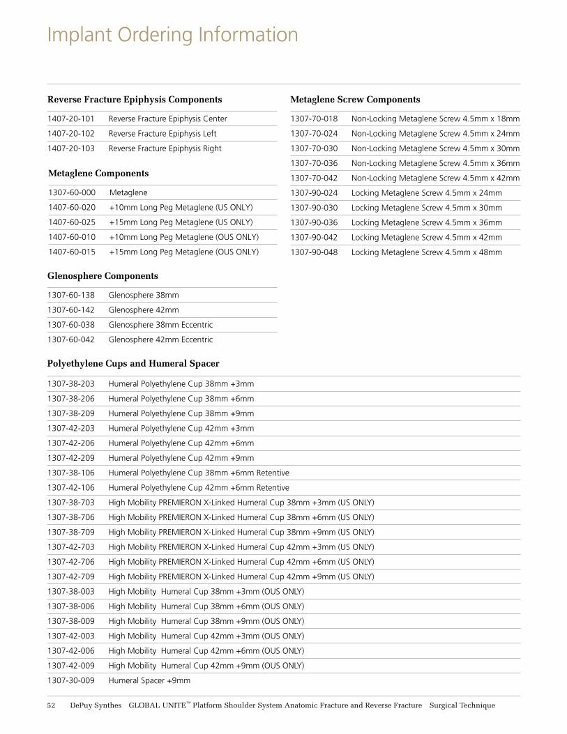
Implant Ordering Information
Metaglene Components
1307-60-000 Metaglene
1407-60-020 +10mm Long Peg Metaglene (US ONLY)
1407-60-025 +15mm Long Peg Metaglene (US ONLY)
1407-60-010 +10mm Long Peg Metaglene (OUS ONLY)
1407-60-015 +15mm Long Peg Metaglene (OUS ONLY)
Reverse Fracture Epiphysis Components
1407-20-101 Reverse Fracture Epiphysis Center
1407-20-102 Reverse Fracture Epiphysis Left
1407-20-103 Reverse Fracture Epiphysis Right
Glenosphere Components
1307-60-138 Glenosphere 38mm
1307-60-142 Glenosphere 42mm
1307-60-038 Glenosphere 38mm Eccentric
1307-60-042 Glenosphere 42mm Eccentric
Metaglene Screw Components
1307-70-018 Non-Locking Metaglene Screw 4.5mm x 18mm
1307-70-024 Non-Locking Metaglene Screw 4.5mm x 24mm
1307-70-030 Non-Locking Metaglene Screw 4.5mm x 30mm
1307-70-036 Non-Locking Metaglene Screw 4.5mm x 36mm
1307-70-042 Non-Locking Metaglene Screw 4.5mm x 42mm
1307-90-024 Locking Metaglene Screw 4.5mm x 24mm
1307-90-030 Locking Metaglene Screw 4.5mm x 30mm
1307-90-036 Locking Metaglene Screw 4.5mm x 36mm
1307-90-042 Locking Metaglene Screw 4.5mm x 42mm
1307-90-048 Locking Metaglene Screw 4.5mm x 48mm
Polyethylene Cups and Humeral Spacer
1307-38-203 Humeral Polyethylene Cup 38mm +3mm
1307-38-206 Humeral Polyethylene Cup 38mm +6mm
1307-38-209 Humeral Polyethylene Cup 38mm +9mm
1307-42-203 Humeral Polyethylene Cup 42mm +3mm
1307-42-206 Humeral Polyethylene Cup 42mm +6mm
1307-42-209 Humeral Polyethylene Cup 42mm +9mm
1307-38-106 Humeral Polyethylene Cup 38mm +6mm Retentive
1307-42-106 Humeral Polyethylene Cup 42mm +6mm Retentive
1307-38-703 High Mobility PREMIERON X-Linked Humeral Cup 38mm +3mm (US ONLY)
1307-38-706 High Mobility PREMIERON X-Linked Humeral Cup 38mm +6mm (US ONLY)
1307-38-709 High Mobility PREMIERON X-Linked Humeral Cup 38mm +9mm (US ONLY)
1307-42-703 High Mobility PREMIERON X-Linked Humeral Cup 42mm +3mm (US ONLY)
1307-42-706 High Mobility PREMIERON X-Linked Humeral Cup 42mm +6mm (US ONLY)
1307-42-709 High Mobility PREMIERON X-Linked Humeral Cup 42mm +9mm (US ONLY)
1307-38-003 High Mobility Humeral Cup 38mm +3mm (OUS ONLY)
1307-38-006 High Mobility Humeral Cup 38mm +6mm (OUS ONLY)
1307-38-009 High Mobility Humeral Cup 38mm +9mm (OUS ONLY)
1307-42-003 High Mobility Humeral Cup 42mm +3mm (OUS ONLY)
1307-42-006 High Mobility Humeral Cup 42mm +6mm (OUS ONLY)
1307-42-009 High Mobility Humeral Cup 42mm +9mm (OUS ONLY)
1307-30-009 Humeral Spacer +9mm

Surgical Technique GLOBAL UNITE™ Platform Shoulder System Anatomic Fracture and Reverse Fracture DePuy Synthes 53
Component Compatibility
Device Component
GLOBAL UNITE System
DELTA XTEND System
Device Component
Device ComponentCompatible Component
Compatible Component
Compatible Component
GLOBAL UNITE Humeral Heads
– GLOBAL UNITE Anatomic Proximal Body – GLOBAL UNITE FX Proximal Body– GLOBAL AP Humeral Stems
(40x12 and 44x12 heads not compatible)– GLOBAL Anchor Peg Glenoid – GLOBAL Crosslinked Anchor Peg Glenoid – GLOBAL Crosslinked Keeled/Fin Glenoid – GLOBAL STEPTECH Anchor Peg Glenoid*
GLOBAL UNITE Modular Suture Collars
– GLOBAL UNITE FX Proximal Body
GLOBAL UNITE Humeral Stems
– GLOBAL UNITE Anatomic Proximal Body– GLOBAL UNITE FX Proximal Body – GLOBAL UNITE Reverse Fracture Epiphysis– DELTA XTEND Modular Epiphysis
GLOBAL UNITE Anatomic Proximal Body
– GLOBAL UNITE Humeral Heads– GLOBAL UNITE Humeral Stems – DELTA XTEND Modular Humeral Stems
GLOBAL UNITE FX Proximal Body
– GLOBAL UNITE Humeral Heads– GLOBAL UNITE Modular Suture Collars– GLOBAL UNITE Humeral Stems – DELTA XTEND Modular Humeral Stems
GLOBAL UNITE Reverse Fracture Epiphysis
– GLOBAL UNITE Humeral Stems– DELTA XTEND Modular Humeral Stems– DELTA XTEND Humeral Spacer– DELTA XTEND Standard Humeral PE Cup– DELTA XTEND X-LINK HIGH MOBILITY
Humeral Cup
DELTA XTEND Monobloc Humeral Cemented Epiphysis
– DELTA XTEND Humeral Spacer– DELTA XTEND Standard Humeral PE Cup– DELTA XTEND X-LINK HIGH MOBILITY
Humeral Cup
DELTA XTEND Modular Humeral Stem
– DELTA XTEND Modular Epiphysis– GLOBAL UNITE Reverse Fracture Epiphysis
DELTA XTEND Modular Epiphysis
– GLOBAL UNITE Humeral Stems– DELTA XTEND Modular Humeral Stems – DELTA XTEND Humeral Spacer– DELTA XTEND Standard Humeral PE Cup– DELTA XTEND X-LINK HIGH MOBILITY
Humeral Cup
DELTA XTEND CTA Head
– DELTA XTEND Modular Epiphysis – DELTA XTEND Monobloc Humeral
Cemented Epiphysis– DELTA XTEND Humeral Spacer
DELTA XTEND Humeral Spacer
– DELTA XTEND Modular Epiphysis – DELTA XTEND Monobloc Humeral
Cemented Epiphysis– GLOBAL UNITE Reverse Fracture Epiphysis– DELTA XTEND Standard Humeral PE Cup– DELTA XTEND X-LINK HIGH MOBILITY
Humeral Cup
DELTA XTEND Standard Humeral PE Cup
– DELTA XTEND Humeral Spacer– DELTA XTEND Modular Epiphysis– GLOBAL UNITE Reverse Fracture Epiphysis– DELTA XTEND Glenosphere
DELTA XTEND X-LINK HIGH MOBILITY Humeral Cup
– DELTA XTEND Humeral Spacer– DELTA XTEND Modular Epiphysis– GLOBAL UNITE Reverse Fracture Epiphysis– DELTA XTEND Glenosphere
DELTA XTEND Glenosphere
– DELTA XTEND Metaglene– DELTA XTEND Metaglene Long Peg– DELTA XTEND Standard Humeral PE Cup– DELTA XTEND X-LINK HIGH MOBILITY
Humeral Cup
DELTA XTEND Metaglene
– DELTA XTEND Glenosphere– DELTA XTEND Non-Locking
Metaglene Screw– DELTA XTEND Locking Metaglene Screw
DELTA XTEND Metaglene Long Peg
– DELTA XTEND Glenosphere– DELTA XTEND Non-Locking Metaglene
Screw– DELTA XTEND Locking Metaglene Screw
DELTA XTEND Non-Locking Metaglene Screw
– DELTA XTEND Metaglene– DELTA XTEND Metaglene Long Peg
DELTA XTEND Locking Metaglene Screw
– DELTA XTEND Metaglene– DELTA XTEND Metaglene Long Peg
* GLOBAL STEPTECH Anchor Peg Glenoid is currently only approved for use in the United States and Canada.

54 DePuy Synthes GLOBAL UNITE™ Platform Shoulder System Anatomic Fracture and Reverse Fracture Surgical Technique
Indications for Use
The GLOBAL UNITE™ Platform Shoulder System is intended for cemented or uncemented total or hemi-shoulderarthroplasty in treatment of the following:
• A severely painful and/or disabled joint resulting from osteoarthritis, traumatic arthritis or rheumatoid arthritis
• Fracture of the proximal humerus where the articular surface is severely comminuted, separated from its blood supply or where the surgeon’s experience indicates that alternative methods of treatment are unsatisfactory
• Irreducible 3- and 4-part fractures of the proximal humerus• Ununited humeral head fractures• Avascular necrosis of the humeral head• Other difficult clinical problems where shoulder arthrodesis
or resection arthroplasty are not acceptable (e.g. revision of a failed primary component)
Hemi-shoulder arthroplasty is also indicated for:
• Deformity and/or limited motion
The GLOBAL UNITE Reverse Fracture Epiphyseal Component, in conjunction with components from the existing DELTA XTEND™ Reverse Shoulder System and GLOBAL UNITE Platform Shoulder System, is indicated for use in a grossly rotator cuff deficient glenohumeral joint with severe arthropathy or a previously failed joint replacement with a gross rotator cuff deficiency. The patient’s joint must be anatomically and structurally suited to receive the selected implant(s), and a functional deltoid muscle is necessary to use the device. It is intended for cemented or uncemented reverse shoulder arthroplasty in treatment of the following:
• Fracture of the proximal humerus where the articular surface is severely comminuted, separated from its blood supply or where the surgeon’s experience indicates that alternative methods of treatment are unsatisfactory
• Irreducible 3- and 4-part fractures of the proximal humerus• Ununited humeral head fractures
The GLOBAL UNITE Reverse Fracture Epiphyseal Component is only intended for use in the treatment of proximal humeral fractures. Bone preparation instrumentation has not been validated to accommodate its use in a nonfracture press-fit application.
GLOBAL UNITE Humeral Stems, in conjunction with existing DELTA XTEND Epiphyseal Components, are indicatedfor use in reverse shoulder arthroplasty in treatment of a grossly deficient rotator cuff joint with severe arthropathyor a previously failed joint replacement with a grossly deficient rotator cuff joint. The patient’s joint must beanatomically and structurally suited to receive the reverse implant(s), and a functional deltoid muscle is necessaryto use the device.
When used in a total shoulder arthroplasty, the GLOBAL UNITE Implants are to be used with DePuy glenoid components. The glenoid components are for cemented use only. GLOBAL UNITE Humeral Implants are for cemented or uncemented use.
When used in a reverse shoulder arthroplasty, the GLOBAL UNITE and DELTA XTEND Humeral Implants are to be used with the HA-coated DELTA XTEND Metaglene Devices. The metaglene implants are intended for uncemented use only with additional screw fixation. The HA-coated DELTA XTEND Humeral Implants are intended for uncemented use only. GLOBAL UNITE Humeral Implants are for cemented or uncemented use.
CONTRAINDICATIONS:The following conditions are contraindications for the total, hemi, or reverse shoulder arthroplasty:1. Active local or systemic infection2. Poor bone quality, such as osteoporosis, where there could
be considerable migration of the prosthesis and/or a chance of fracture of the humerus or glenoid
3. Inadequate bone stock in the proximal humerus or glenoid fossa for supporting the components
4. Non-functioning deltoid
The following conditions are also contraindications only for total and hemi-shoulder arthroplasty:5. Absent, irreparable or nonfunctional rotator cuff or other
essential muscles
Note: Diabetes, at present, has not been established as a contraindication. However, because of increased risk forcomplications such as infection, slow wound healing, etc., the physician should carefully consider the advisability of shoulder replacement in the severely diabetic patient.

Surgical Technique GLOBAL UNITE™ Platform Shoulder System Anatomic Fracture and Reverse Fracture DePuy Synthes 55
Indications for Use
WARNINGS:• Implants and trial components from different
manufacturers should never be used together• Shoulder prosthesis components should never be
re-implanted. Even though the implant appears undamaged, the implant may have developed microscopic imperfections, which could lead to failure
• The use of an anatomic glenoid prosthesis in patients with cuff tear arthropathy could increase the risk of glenoid component loosening due to non-anatomic loading conditions
• Trials should only be used for trialing purposes. Trials should never be used as an implant
• DePuy (Ireland) single use devices have not been designed to undergo or withstand any form of alteration, such as disassembly, cleaning or re-sterilization, after a single patient use. Reuse can potentially compromise device performance and patient safety
• DO NOT USE the 40 x 12 mm or 44 x 12 mm GLOBAL UNITE Standard Humeral Heads with the GLOBAL AP™ Humeral Components, as their compatibility has not been established
MRI SAFETY INFORMATION:The GLOBAL UNITE Shoulder System has not been tested for safety and compatibility in the MR environment. The devices have not been tested for heating or migration in the MR environment. Scanning a patient who has this device may result in patient injury.
The risks associated with other passive implants in an MR environment have been evaluated and are known to include heating, migration, and image artifacts at or near the implant site.
PRECAUTIONS: The following conditions, singularly or concurrently, tend to impose severe loading on the affected extremity,thereby placing the patient at higher risk for failure of the shoulder arthroplasty:
1. Obesity or excessive patient weight2. Manual labor3. Active sports participation4. High levels of patient activity5. Likelihood of falls6. Alcohol or drug addictions7. Other disabilities, as applicable
The following conditions singularly or concurrently, tend to adversely affect the fixation of shoulder replacement implants:1. Marked osteoporosis or poor bone stock2. Metabolic disorders or systemic pharmacological
treatments leading to progressive deterioration of solid bone support for the implant (e.g., diabetes mellitus, steroid therapies, immunosuppressive therapies, etc.)
3. History of general or local infections4. Severe deformities leading to impaired fixation or improper
positioning of the implant5. Tumors of the supporting bone structures6. Allergic reactions to implant materials
(e.g., bone cement, metal)7. Tissue reactions to implant corrosion or implant wear debris8. Disabilities of other joints
When the surgeon determines that total shoulder or hemi shoulder replacement is the best medical option available anddecides to use this prosthesis in a patient who has any of the above conditions or who is simply young and active, it isimperative that the patient be instructed about the strength limitations of the material used in the device and for fixation, and the resulting need to substantially reduce or eliminate any of the above conditions, when possible.
INFORMATION FOR USEThe surgical and postoperative management of the patient must be carried out with due consideration for all existingconditions. Mental attitudes or disorders resulting in a patient’s failure to adhere to the surgeon’s orders may delay postoperative recovery and/or increase the risk of adverse effects including implant or implant fixation failure. The functional life expectancy of prosthetic shoulders is, at present, not clearly established.

Limited Warranty and Disclaimer: DePuy Synthes products are sold with a limited warranty to the original purchaser against defects in workmanship and materials. Any other express or implied warranties, including warranties of merchantability or fitness, are hereby disclaimed.
Please also refer to the package insert(s) or other labeling associated with the devices identified in this surgical technique for additional information.
CAUTION: Federal Law restricts these devices to sale by or on the order of a physician.
Some devices listed in this surgical technique may not have been licensed in accordance with Canadian law and may not be for sale in Canada. Please contact your sales consultant for items approved for sale in Canada.
Not all products may currently be available in all markets.
DePuy Orthopaedics, Inc.700 Orthopaedic DriveWarsaw, IN 46582USATel: +1 (800) 366-8143Fax: +1 (800) 669-2530
www.depuysynthes.com
© DePuy Synthes 2018. All rights reserved.DSUS/JRC/0315/0763 Rev 2 DSEM/JRC/0218/1003 02/18
DePuy (Ireland)Loughbeg, RingaskiddyCo.Cork, IrelandTel: +35 (321) 491 4000 Fax: +35 (321) 491 4199
DePuy France S.A.S 7 allée Irène Joliot Curie CS 30078 69801 SAINT PRIEST Cedex Tel : +33 (0)4 72 79 27 27 Fax : +33 (0)4 72 79 28 28
0459
Greatbatch Medical10000 Wehrle DriveClarence, NY 14031USATel: +1 716 759 5600Fax: +1 716 759 5654
0086
DePuy International, Ltd.St Anthony’s RoadLeeds LS11 8DTEnglandTel: +44 (0) 113 270 0461
Related Documents


