1 Analytical Prediction of Leaf Spring Bushing Loads Using MSC/NASTRAN and MDI/ADAMS Shahriar Tavakkoli Farhang Aslani David S. Rohweder Ford Motor Company Dearborn, Michigan Satyendra Savanur Automated Analysis Corporation Ann Arbor, Michigan ABSTRACT Analytical loads in leaf spring bushing can be used to perform finite element analysis on brackets that connect the leaf spring to a truck frame. Two models of leaf spring in MSC/NASTRAN and MDI/ADAMS were created to compare the bushing loads predicted by each model. Geometric non-linear capability of MSC/NASTRAN (SOL 106) was used to predict the bushing loads in MSC/NASTRAN model. The quasi-static simulation capability of MDI/ADAMS was used to predict the bushing loads in MDI/ADAMS model. The analyses simulated the standard jounce and roll tests at The University of Michigan Transportation Research Institute (UMTRI). An accurate prediction of loads in MSC/NASTRAN model provides the benefit of integration that allows us to include the leaf spring model in a full vehicle˝model to simulate full vehicle lab tests as well as proving ground durability events. Good correlation was obtained between the two models in jounce condition. More effort is underway to establish satisfactory correlation for roll condition.

Welcome message from author
This document is posted to help you gain knowledge. Please leave a comment to let me know what you think about it! Share it to your friends and learn new things together.
Transcript

1
Analytical Prediction ofLeaf Spring Bushing Loads Using
MSC/NASTRAN and MDI/ADAMS
Shahriar TavakkoliFarhang Aslani
David S. RohwederFord Motor CompanyDearborn, Michigan
Satyendra SavanurAutomated Analysis Corporation
Ann Arbor, Michigan
ABSTRACT
Analytical loads in leaf spring bushing can be used to perform finite element analysis onbrackets that connect the leaf spring to a truck frame. Two models of leaf spring inMSC/NASTRAN and MDI/ADAMS were created to compare the bushing loadspredicted by each model. Geometric non-linear capability of MSC/NASTRAN (SOL 106)was used to predict the bushing loads in MSC/NASTRAN model. The quasi-staticsimulation capability of MDI/ADAMS was used to predict the bushing loads inMDI/ADAMS model. The analyses simulated the standard jounce and roll tests at TheUniversity of Michigan Transportation Research Institute (UMTRI). An accurateprediction of loads in MSC/NASTRAN model provides the benefit of integration thatallows us to include the leaf spring model in a full vehicle˝model to simulate full vehicle labtests as well as proving ground durability events. Good correlation was obtained betweenthe two models in jounce condition. More effort is underway to establish satisfactorycorrelation for roll condition.

2
1. Introduction
Large displacements cause geometric non-linear behavior in leaf spring
suspensions of a truck. A typical front suspension system of a truck is shown in Figure 1.
The finite element model of a front suspension is shown in Figure 2. When the loads are
applied at the tire patch or spindle point, they are transmitted through the suspension
components to the rest of the structure. The distribution of spindle load through the leaf
spring generates bushing forces that are applied to spring hanger and shackle brackets.
The brackets connect the leaf spring to the truck frame. Analytically predicted bushing
loads can be used to perform finite element (FE) analysis of the bracket before the
availability of the first prototype.
The purpose of this study was to compare the predicted bushing loads of the front
suspension of a heavy truck under standard University of Michigan Transportation
Research Institute (UMTRI) jounce and roll tests from MSC/NASTRAN and
MDI/ADAMS models.

3
2. Model Description
Two models of a typical heavy truck leaf spring were created for this study. The
first model was created using Hypermesh which is the preprocessor used for
MSC/NASTRAN. The second model was created in MDI/ADAMS.
2.1 Leaf Spring Description of MSC/NASTRAN Model
A model of single leaf spring was created in MSC/NASTRAN (Figure 3). Each
element of the leaf spring is made of general purpose beam elements with constant
rectangular cross section. The cross sections of the beam elements are decreased from the
spring seat to the spring eyes in order to represent the thickness. Ten elements were
created along the front end of the leaf spring. Similarly, ten elements were created along
the rear end of the leaf spring . The general purpose beam element of MSC/NASTRAN
has a total of 14 degrees of freedom and can be used to build suspension mechanism. The
spring and the shackle eyes are represented by pin joints in the FE model. The strain free
rotation of the pin joints is also represented to simulate the large displacement and pin-
joint mechanisms of the leaf spring.

4
2.2 MDI/ADAMS MODEL
In the MDI/ADAMS model, the beam elements are of constant cross section
similar to the FE model created in MSC/NASTRAN. A total of 20 elements were used to
create the single leaf spring model. The shackle is modeled as a rigid part. The pin joints
are represented by revolute joints with one degree of freedom˝along the global y-axis. The
forces and moments are applied at the axle seat. A model of the MDI/ADAMS single leaf
spring is shown in Figure 4. It should be noted that the corresponding beam elements
created in both the MSC/NASTRAN and MDI/ADAMS models were of equal length and
equal inertia properties. Maximum efforts were made in order to create similar models in
both software in order to prevent errors due to modeling˝discrepancies.
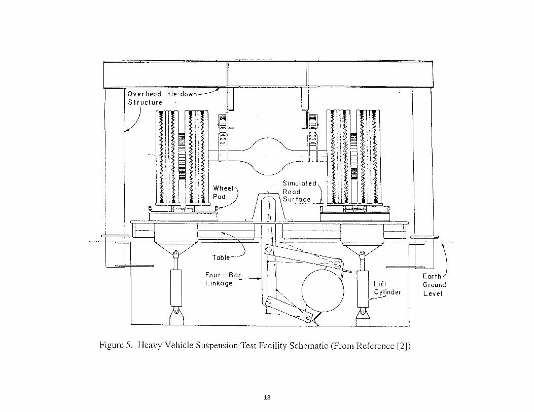
3. UMTRI Testing Facility
A facility for the measurement of heavy truck suspension properties exists at the
University of Michigan Transportation Research Institute (UMTRI) [2]. The UMTRI
facility has three major mechanical systems including a static structure, a movable table,
and four wheel pad assemblies. The facility is also equipped with a computerized data
acquisition and control electronics for primary data˝collection and display. Figure 5 shows
a schematic of the heavy vehicle suspension test facility.

5
The load cases in this study simulated the UMTRI heavy vehicle suspension
testing. In a jounce test, the axle is forced to move in the vertical direction with no roll
component (relative to the vehicle frame). The force-deflection data is collected for the
vertical spring rate. This data is further reduced to a vertical force-deflection curve for
each individual spring to calculate the vertical stiffness.
In a roll test, the total suspension load is brought to the desired level. Then, while
the load is held constant, the table is rolled in order to apply a roll moment to the
suspension and the data is recorded. The moment-rotation angle is then plotted in order
to calculate the rotational stiffness of the suspension.
4. Analysis Discussion
Large displacements of leaf spring lead to geometric non-linear behavior.
Therefore, SOL 106 [3] of MSC/NASTRAN was used to account for geometric non-
linearity. The quasi-static simulation [4] of MDI/ADAMS was used for the ADAMS
model. The forces and moments were applied gradually at the center of the spring seat
location for numerical stability reasons. Jounce load was applied in several steps. In the
roll test simulation, the leaf spring was subjected to a˝moment to simulate a 10 degree roll

6
of the vehicle. Since our model only included a single leaf spring, an equivalent roll
moment was applied at the spring seat location to simulate˝the roll test case.
5. Results and Conclusions
The reaction forces and moments in the front spring eye and in the shackle joints from
MSC/NASTRAN model were compared to those from MDI/ADAMS model. The
displacement of the seat location was also used for˝comparison. Tables 1-5 show the ratio
of the results from MSC/NASTRAN model to those from MDI/ADAMS model. The
results are discussed in the following sections.
5.1 Jounce Test Simulation
The Jounce test simulation results shown in Table 1 indicate a good correlation
between MSC/NASTRAN and MDI/ADAMS forces. The forces are compared in two
locations, in the front eye and, in the frame/shackle location. Displacements are
compared at spring seat location and the results have good correlation (Table 2). The
accuracy of jounce results is within 5% and indicates the predicted forces from
MSC/NASTRAN can be used for component level stress analyses. Figure 6 shows the
graphical representation of the Jounce test simulation˝results.

7
5.2 Roll Test Simulation
In the Roll test simulation, there is a variation of up to 11% in forces (Table 3),
and up to 34% variation in moments (Table 4). The displacements and rotations also
show no correlation. It can be seen from Tables 3 through 5 that when the pin joints are
locked in the models, the behavior of the system is altered dramatically as reflected by the
ratio of forces, moments, and displacements. The correlation of the results in the roll test
were very poor and unacceptable. The cause of this is under investigation. Figures 7 and
8 show the graphical representation of the Roll test˝simulation results.
6. References
1. Norman A. and Scharff R., “Heavy-Duty Truck Systems”,˝Delmar Publishers Inc.,
1991.
2. Winkler, C.B., Hagan, M, “A Test Facility for the˝Measurement of Heavy Vehicle
Suspension Parameters”, SAE Paper No. 800906, 1981.
3. MSC/NASTRAN Handbook for Non-Linear Analysis, Version 67,˝The MacNeal-
Schwendler Corporation, Los Angles, CA, March 1992.
4. MDI/ADAMS Solver Reference Manual, Version 8, Mechanical˝Dynamics, Ann
Arbor, MI.

8
Table 1. Ratio of NASTRAN to ADAMS forces in Jounce˝simulation
Location Fx Fy FzShackle/Body 1.01 0.0 1.01
Front Eye 1.01 0.0 0.95
Table 2. Ratio of NASTRAN to ADAMS Displacements in Jounce˝simulation
Location X Y ZSpring Seat 1.04 0.0 1.0
Table 3. Ratio of NASTRAN to ADAMS Forces in Roll˝simulation
Free Shackle/Frame Joint Locked Shackle/Frame JointLocation Fx Fy Fz Fx Fy Fz
Shackle/Frame 0.0 1.0 0.0 1.11 1.0 1.11Front Eye 0.0 1.09 0.0 1.11 1.0 1.09
Table 4. Ratio of NASTRAN to ADAMS Moments in Roll˝simulation
Free Shackle/Frame Joint Locked Shackle/Frame JointLocation Mx My Mz Mx My Mz
Shackle/Frame 1.00 0.0 0.92 1.17 0.9 0.85Front Eye 1.00 0.0 0.9 0.96 0.0 0.66
Table 5. Ratio of NASTRAN to ADAMS Displacements in Roll˝simulation at Spring SeatLocation
Free Shackle/Frame Joint Locked Shackle/Frame JointX Y Z X Y Z
Displacement 1.04 0.91 1.07 1.27 2.87 1.43Rotation 1.22 0.71 1.14 1.28 1.13 1.27

9

10

11

12
13

14

15

16
Related Documents