Analytical Model for FRP Confinement of Concrete Columns with and without Internal Steel Reinforcement Carlo Pellegrino 1 and Claudio Modena 2 Abstract: The paper aims to contribute to a better understanding of the behavior of reinforced concrete columns confined with fiber- reinforced polymer FRP sheets. In particular, some new insights on interaction mechanisms between internal steel reinforcement and external FRP strengthening and their influence on efficiency of FRP confinement technique are given. In this context a procedure to generate the complete stress-strain response including new analytical proposals for 1 effective confinement pressure at failure; 2 peak stress; 3 ultimate stress; 4 ultimate axial strain; and 5 axial strain corresponding to peak stress for FRP confined elements with circular and rectangular cross sections, with and without internal steel reinforcement, is presented. Interaction mechanisms between internal steel reinforcement and external FRP strengthening, shown by some experimental results obtained at the University of Padova with accurate measurements, are taken into account in the analytical model. Four experimental databases regarding FRP confined concrete columns, with circular and rectangular cross section with and without steel reinforcement, are gathered for the assessment of some of the confinement models shown in literature and the new proposed model. The proposed model shows a good performance and analytical stress-strain curves approximate some available test results quite well. DOI: 10.1061/ASCECC.1943-5614.0000127 CE Database subject headings: Fiber reinforced polymer; Confinement; Reinforced concrete; Analytical techniques; Concrete columns. Author keywords: FRP; Confinement; Reinforced concrete; Analytical modeling. Introduction A number of existing RC structures need rehabilitation or strengthening because of improper design or construction, change of the design loads, damage caused by environmental factors or seismic events. Structural behavior of fiber-reinforced polymer FRP strengthened RC elements has been widely studied over the last few decades and some studies have resulted in the first design guidelines for strengthened concrete. American ACI 440–02 American Concrete Institute 2002, European fib bulletin 14 fédération internationale du béton 2001 and Italian Recommen- dations CNR-DT 200 2004 Italian Research Council CNR Ad- visory Committee on Technical Recommendations for Construction 2004 are examples of such guidelines. In this con- text, a number of experimental programs and analytical studies have been developed in the last few years at the University of Padova focusing on the interaction between existing internal steel and external FRP reinforcement Pellegrino and Modena 2002, 2006, 2008. The theme of confinement of RC elements subjected to preva- lent compressive actions in order to increase strength and ductility is actually a very complex problem and not completely solved especially for circular and rectangular columns with existing steel reinforcement. In fact, interaction mechanisms between internal steel reinforcement and external FRP do not seem to be suffi- ciently investigated especially in relation to the efficiency of FRP confinement technique. Analytical models actually present in lit- erature e.g., fédération internationale du béton 2001; American Concrete Institute 2002; Italian Research Council CNR Advi- sory Committee on Technical Recommendations for Construction 2004; Fardis and Khalili 1981; Kawashima et al. 2000; Ilki and Kumbasar 2003; Lam and Teng 2003; Li et al. 2003; Matthys et al. 2006; Harajli et al. 2006; Tastani et al. 2006; Ilki et al. 2008 are mainly calibrated with experimental studies without taking into consideration the influence of the existing steel reinforcement on the structural behavior of the FRP confined element. Analytical models actually available in literature usually cor- relate the increase of strength and ductility with the confinement pressure. According to most of the writers and codes the confine- ment pressure is considered equal to that due to FRP only ne- glecting the eventual contribution of the internal transverse steel reinforcement, whereas only some of the most recent analytical models Kawashima et al. 2000; Li et al. 2003; Harajli et al. 2006; Tastani et al. 2006; Ilki et al. 2008 estimate the total confinement pressure as the sum of the confinement pressure due to the exter- nal FRP jacketing, f lf , and the confinement pressure due to the internal transverse steel reinforcement stirrups or spirals, f ls , eventually present. In these models, the interaction between FRP and steel contemporary confinement actions and its influence on the effectiveness of the FRP confinement technique are not ex- plicitly considered. 1 Assistant Professor, Dept. of Structural and Transportation Engineer- ing, Univ. of Padova, Via Marzolo 9, 35131 Padova corresponding au- thor. E-mail: [email protected] 2 Professor, Dept. of Structural and Transportation Engineering, Univ. of Padova, Via Marzolo 9, 35131 Padova. E-mail: claudio.modena@ unipd.it Note. This manuscript was submitted on August 19, 2009; approved on April 1, 2010; published online on April 7, 2010. Discussion period open until May 1, 2011; separate discussions must be submitted for indi- vidual papers. This paper is part of the Journal of Composites for Con- struction, Vol. 14, No. 6, December 1, 2010. ©ASCE, ISSN 1090-0268/ 2010/6-693–705/$25.00. JOURNAL OF COMPOSITES FOR CONSTRUCTION © ASCE / NOVEMBER/DECEMBER 2010 / 693 Downloaded 15 Nov 2010 to 147.162.29.67. Redistribution subject to ASCE license or copyright. Visit http://www.ascelibrary.org

Welcome message from author
This document is posted to help you gain knowledge. Please leave a comment to let me know what you think about it! Share it to your friends and learn new things together.
Transcript

Analytical Model for FRP Confinement of Concrete Columnswith and without Internal Steel Reinforcement
Carlo Pellegrino1 and Claudio Modena2
Abstract: The paper aims to contribute to a better understanding of the behavior of reinforced concrete columns confined with fiber-reinforced polymer �FRP� sheets. In particular, some new insights on interaction mechanisms between internal steel reinforcement andexternal FRP strengthening and their influence on efficiency of FRP confinement technique are given. In this context a procedure togenerate the complete stress-strain response including new analytical proposals for �1� effective confinement pressure at failure; �2� peakstress; �3� ultimate stress; �4� ultimate axial strain; and �5� axial strain corresponding to peak stress for FRP confined elements withcircular and rectangular cross sections, with and without internal steel reinforcement, is presented. Interaction mechanisms betweeninternal steel reinforcement and external FRP strengthening, shown by some experimental results obtained at the University of Padovawith accurate measurements, are taken into account in the analytical model. Four experimental databases regarding FRP confined concretecolumns, with circular and rectangular cross section with and without steel reinforcement, are gathered for the assessment of some of theconfinement models shown in literature and the new proposed model. The proposed model shows a good performance and analyticalstress-strain curves approximate some available test results quite well.
DOI: 10.1061/�ASCE�CC.1943-5614.0000127
CE Database subject headings: Fiber reinforced polymer; Confinement; Reinforced concrete; Analytical techniques; Concretecolumns.
Author keywords: FRP; Confinement; Reinforced concrete; Analytical modeling.
Introduction
A number of existing RC structures need rehabilitation orstrengthening because of improper design or construction, changeof the design loads, damage caused by environmental factors orseismic events. Structural behavior of fiber-reinforced polymer�FRP� strengthened RC elements has been widely studied over thelast few decades and some studies have resulted in the first designguidelines for strengthened concrete. American ACI 440–02�American Concrete Institute 2002�, European fib bulletin 14�fédération internationale du béton 2001� and Italian Recommen-dations CNR-DT 200 2004 �Italian Research Council �CNR� Ad-visory Committee on Technical Recommendations forConstruction 2004� are examples of such guidelines. In this con-text, a number of experimental programs and analytical studieshave been developed in the last few years at the University ofPadova focusing on the interaction between existing internal steeland external FRP reinforcement �Pellegrino and Modena 2002,2006, 2008�.
The theme of confinement of RC elements subjected to preva-
1Assistant Professor, Dept. of Structural and Transportation Engineer-ing, Univ. of Padova, Via Marzolo 9, 35131 Padova �corresponding au-thor�. E-mail: [email protected]
2Professor, Dept. of Structural and Transportation Engineering, Univ.of Padova, Via Marzolo 9, 35131 Padova. E-mail: [email protected]
Note. This manuscript was submitted on August 19, 2009; approvedon April 1, 2010; published online on April 7, 2010. Discussion periodopen until May 1, 2011; separate discussions must be submitted for indi-vidual papers. This paper is part of the Journal of Composites for Con-struction, Vol. 14, No. 6, December 1, 2010. ©ASCE, ISSN 1090-0268/
2010/6-693–705/$25.00.JOURNAL OF COMPOSITES F
Downloaded 15 Nov 2010 to 147.162.29.67. Redistribu
lent compressive actions in order to increase strength and ductilityis actually a very complex problem and not completely solvedespecially for circular and rectangular columns with existing steelreinforcement. In fact, interaction mechanisms between internalsteel reinforcement and external FRP do not seem to be suffi-ciently investigated especially in relation to the efficiency of FRPconfinement technique. Analytical models actually present in lit-erature �e.g., fédération internationale du béton 2001; AmericanConcrete Institute 2002; Italian Research Council �CNR� Advi-sory Committee on Technical Recommendations for Construction2004; Fardis and Khalili 1981; Kawashima et al. 2000; Ilki andKumbasar 2003; Lam and Teng 2003; Li et al. 2003; Matthys etal. 2006; Harajli et al. 2006; Tastani et al. 2006; Ilki et al. 2008�are mainly calibrated with experimental studies without takinginto consideration the influence of the existing steel reinforcementon the structural behavior of the FRP confined element.
Analytical models actually available in literature usually cor-relate the increase of strength and ductility with the confinementpressure. According to most of the writers and codes the confine-ment pressure is considered equal to that due to FRP only �ne-glecting the eventual contribution of the internal transverse steelreinforcement�, whereas only some of the most recent analyticalmodels �Kawashima et al. 2000; Li et al. 2003; Harajli et al. 2006;Tastani et al. 2006; Ilki et al. 2008� estimate the total confinementpressure as the sum of the confinement pressure due to the exter-nal FRP jacketing, f lf, and the confinement pressure due to theinternal transverse steel reinforcement �stirrups or spirals�, f ls,eventually present. In these models, the interaction between FRPand steel contemporary confinement actions and its influence onthe effectiveness of the FRP confinement technique are not ex-
plicitly considered.OR CONSTRUCTION © ASCE / NOVEMBER/DECEMBER 2010 / 693
tion subject to ASCE license or copyright. Visithttp://www.ascelibrary.org
In most cases, the confinement pressure f lf due to FRP wrap-ping is computed as
f lf =1
2kf� fEf� f
eff �1�
where Ef =elastic modulus of the FRP strengthening and � f
=FRP strengthening ratio, equal to
� f =4nftf
D�circular columns� �2a�
� f =2nftf�b + h�
bh�rectangular columns� �2b�
being nf and tf the number of FRP layers and the thickness of thesingle FRP layer, respectively, and D, b, and h the geometricdimensions of the cross section �diameter D for circular crosssections, width b, and height h for rectangular cross sections�.
kf is the coefficient of efficiency of the confinement, and canbe computed as the following product of coefficients:
kf = k� · kv · kh �3�
The coefficient of horizontal efficiency kh can be defined as
kh = 1 −�b − 2r�2 + �h − 2r�2
3bh�4�
This coefficient takes into account the “arch effect” near thecorners of rectangular cross sections which reduces the effectivelyconfined area to a fraction of the overall concrete cross section�Italian Research Council �CNR� Advisory Committee on Techni-cal Recommendations for Construction 2004�. This effect de-pends on the corner radius r.
The coefficient of vertical efficiency kv, takes into account, fordiscontinuous wrapping, the reduction in the confinement effec-tiveness due to the diffusion of stresses �approximately at 45°�between two subsequent wrappings �Italian Research Council�CNR� Advisory Committee on Technical Recommendations forConstruction 2004; fédération internationale du béton 2001�.Hence the coefficient of vertical efficiency kv does not depend onthe shape of the cross section but it depends on the configurationof the wraps along the longitudinal axis of the element
kv = �1 −pf�
2 · dmin�2
�5�
where pf�=net distance between two subsequent wraps and dmin
=minimum cross section of the member. For RC confined mem-bers with continuous FRP wrapping, kv=1 is assumed.
The coefficient k� has to be used when fibers are spirally in-stalled with an angle � with respect to the member cross sectionand can be expressed as follows �Italian Research Council �CNR�Advisory Committee on Technical Recommendations for Con-struction 2004�:
k� =1
1 + tan2 ��6�
The term � feff in Eq. �1� is the effective hoop FRP strain. Ac-
cording to the experimental results available in literature, thisstrain is less than the ultimate FRP strain � fu. On this basis, mostof the analytical models reduce the ultimate FRP strain � fu, for thecalculation of the confinement pressure at failure, with a coeffi-
cient of efficiency of the FRP strengthening k�694 / JOURNAL OF COMPOSITES FOR CONSTRUCTION © ASCE / NOVE
Downloaded 15 Nov 2010 to 147.162.29.67. Redistribu
� feff = k� · � fu �7�
Xiao and Wu �2000� and Matthys et al. �2005� suggested, ac-cording to their experimental results, the value of k�=0.5,whereas Lam and Teng �2003� proposed various values, accord-ing to the type of composite used, between 0.6 and 0.85.
For columns with internal steel stirrups or spirals, the confine-ment pressure due to transverse reinforcement is usually calcu-lated as
f ls =1
2ks�stf y,st �8�
where �st=transverse steel ratio; fy,st=yield stress of the trans-verse steel reinforcement; and ks=coefficient of efficiency for theconfining transverse steel. Eq. �8� is based on the approach pro-posed by Sheikh and Uzumeri �1980� and Mander et al. �1988�.The coefficient of efficiency ks for the confining transverse steel isgiven by
ks = keskv �9�
where kes=coefficient of horizontal efficiency defined as
kes =1 − � �wxi
2 + wyi2 �/6xy
1 − �cc�10�
being kes=1 for circular cross sections.kv is the coefficient of vertical efficiency defined as
kv =�1 −
s�
2ds�2
1 − �cc
for circular columns confined with circular stirrups
�11�
kv =�1 −
s�
2ds�
1 − �ccfor circular columns confined with spirals
�12�
kv =�1 − s�/2x��1 − s�/2y�
1 − �ccfor rectangular columns �13�
In the above expressions, x and y=dimensions of the stirrups; wxi
and wyi=distances between two longitudinal bars along the twomain directions in the cross section plane; �cc=longitudinal steelratio; ds=diameter of the stirrups/spirals; and s�=net distance be-tween two stirrups/spirals. More details on confinement of con-crete columns with transverse steel can be found in Mander et al.�1988�.
The main aim of the present research is to provide better un-derstanding of the effect of interaction between external FRP con-finement and internal steel reinforcement on the stress-strainresponse of RC columns. This interaction is particularly importantsince internal steel reinforcement configuration influences con-crete cracking pattern at failure and therefore the efficiency ofFRP strengthening technique in terms of ultimate capacity andductility.
In this context, a procedure to generate the complete stress-strain response including new analytical proposals for �1� effec-tive confinement pressure at failure; �2� peak stress; �3� ultimate
stress; �4� ultimate axial strain; and �5� axial strain correspondingMBER/DECEMBER 2010
tion subject to ASCE license or copyright. Visithttp://www.ascelibrary.org

to peak stress for FRP confined elements with circular and rect-angular cross section, with and without internal steel reinforce-ment, are presented taking into account the interactionmechanisms between internal steel reinforcement and externalFRP strengthening. These mechanisms are shown by observingfailure modes and accurately measuring hoop strains along theperimeter of the column in an experimental investigation devel-oped at the University of Padova.
An assessment of some of the actual confinement models andthe new proposals was developed according to the experimentalresults available in literature.
Experimental Database
A database with experimental results available in literature re-garding axial compression tests of FRP confined concrete col-umns was gathered and subdivided in four parts: columns �1� withcircular cross section and without steel reinforcement; �2� withcircular cross section and steel reinforcement; �3� with rectangu-lar cross section and without steel reinforcement; and �4� withrectangular cross section and steel reinforcement. In this database,the experimental values of peak stress, ultimate stress, ultimateaxial strain, and axial strain corresponding to peak stress are in-cluded for each specimen together with the geometrical charac-teristics of the specimen and mechanical properties of thematerials �concrete, steel, and FRP�.
Characteristics and experimental results for 219 FRP confinedcircular columns without steel reinforcement shown in the worksof Arduini et al. �1999�, Berthet et al. �2005�, Carey and Harries�2005�, Harmon and Slattery �1992�, Harries and Carey �2003�,Kono et al. �1998�, Li et al. �2003�, Matthys et al. �1999�, Micelliet al. �2001�, Miyauchi et al. �1997�, Pellegrino et al. �2004�,Pessiki et al. �2001�, Picher et al. �1996�, Rochette and Labossiére�2000�, Rousakis �2001�, Shahawy et al. �2000�, Silva and Rod-rigues �2006�, Teng and Lam �2004�, Tinazzi et al. �2003�, Tou-tanji �1999�, Wang and Wu �2008�, and Watanabe et al. �1997� areincluded in the database �a�.
Characteristics and experimental results for 77 FRP confinedcircular columns with steel reinforcement shown in the works ofArduini et al. �1999�, Carey and Harries �2005�, Demers andNeale �1999�, Esfahani and Kianoush �2004�, Ilki et al. �2008�, Liet al. �2003�, Lin and Liao �2004�, Matthys et al. �2006�, Parrettiand Nanni �2002�, Pellegrino et al. �2004�, Pessiki et al. �2001�,Rodrigues and Silva �2001�, and Tinazzi et al. �2003� are includedin the database �b�.
Characteristics and experimental results for 135 FRP confinedrectangular columns without steel reinforcement shown in theworks of Braga et al. �2004�, Campione �2006�, Chaallal et al.�2003�, Harajli �2006�, Harries and Carey �2003�, Ilki and Kum-basar �2003�, Mirmiran et al. �1998�, Mukherjee et al. �2004�,Parvin and Wang �2002�, Pessiki et al. �2001�, Rochette and La-bossiére �2000�, Rousakis et al. �2007�, and Wang and Wu �2008�are included in the database �c�.
Characteristics and experimental results for 156 FRP confinedrectangular columns with steel reinforcement shown in the worksof Braga et al. �2004�, Cole and Belarbi �2001�, De Paula and DaSilva �2002�, Esfahani and Kianoush �2004�, Feng et al. �2002�,Harajli et al. �2006�, Hosseini and Fadaee �2004�, Ilki et al.�2008�, Maalej et al. �2003�, Parretti and Nanni �2002�, Pessiki etal. �2001�, Prota et al. �2006�, Tan �2002�, and Tastani et al.
�2006� are included in the database �d�.JOURNAL OF COMPOSITES F
Downloaded 15 Nov 2010 to 147.162.29.67. Redistribu
Proposed Analytical Model
The aim of this study is to propose an analytical model to predictstrength and ductility and generate a complete stress-strain curvefor FRP confined axially loaded elements with particular attentionto the role of the existing internal steel reinforcement taking intoaccount the interaction mechanisms, actually not considered inthe main models and the codes, between internal steel reinforce-ment and external FRP wrapping.
The behavior of columns with and without steel reinforcementwas distinguished in the definition of the analytical model since,according to previous experimental investigations �Pellegrino etal. 2004; Tinazzi et al. 2003�, presence of internal steel reinforce-ment can effectively influence overall structural behavior of con-fined columns at the ultimate limit state and, as a consequence,efficiency of the strengthening technique. In particular, accordingto previous experimental investigations �Pellegrino et al. 2004;Tinazzi et al. 2003�, the increment of strength, due to FRP con-finement only, for the columns with internal steel reinforcement,is less than that for the columns without steel reinforcement �evenif the overall increment of strength, with respect to concrete only,for the columns with internal steel reinforcement and externalFRP is more than that for the columns without steel reinforcementand external FRP, due to the additional contribution of confiningsteel stirrups�.
In this work, analytical proposals are different for circular andrectangular cross sections according to most of the existing mod-els �e.g., ACI 440-02 �American Concrete Institute 2002�, fib bul-letin 14 �fédération internationale du béton 2001�, ItalianRecommendations CNR-DT 200 2004 �Italian Research Council�CNR� Advisory Committee on Technical Recommendations forConstruction 2004�, Lam and Teng 2003, Ilki and Kumbasar2003�, since rectangular columns usually show an increment ofstrength less than the corresponding circular ones and an incre-ment of ductility more than the corresponding circular ones.Hence the analytical model proposes different expressions for thefour FRP confined concrete column typologies �circular and rect-angular, with and without internal steel reinforcement�. Regardingthe contribution of the unconfined concrete, for simplicity, it wassupposed that it does not depend on the current strain state whichis difficult to be predicted in the design phase.
Effective Confining Pressure at Failure
The total confining pressure Pu can be computed as the sum of thecontributions due to FRP wrapping f lf and transverse steel rein-forcement f ls, reduced with the ratio Acc /Ag, where Acc=area ofthe cross section included in the transverse steel and Ag=area ofthe overall cross section
Pu = f lf + f ls · Acc/Ag �14�
The confining pressure exerted by the transverse steel �even-tually present� can be calculated with Eq. �8�. The coefficient ofefficiency of the FRP k�, included in Eq. �7�, is defined in differ-ent ways for columns with and without internal steel reinforce-ment.
Regarding FRP confined columns without steel reinforcement,the main cause of the FRP efficiency reduction is the excessivecurvature at the corners of the rectangular columns which, apartfrom reducing the effectively confined area to a fraction of theoverall concrete cross section �and this is taken into account withthe coefficient kh in Eq. �4��, causes stress concentrations in the
FRP near the corners and therefore a reduction of the maximumOR CONSTRUCTION © ASCE / NOVEMBER/DECEMBER 2010 / 695
tion subject to ASCE license or copyright. Visithttp://www.ascelibrary.org

FRP stress at failure. According to the wide experimental data-base, the following value of the coefficient k� can be obtained forthe columns without steel reinforcement, with a linear regressionof the experimental data:
k� = 0.25 + 0.25�2r/b� �15�
For 2r /b=1 �circular columns without steel reinforcement�, k�
=0.5.For concrete columns with steel reinforcement it was found
that the coefficient k� does not clearly depend on 2r /b. This isprobably due to the action of the stirrups near the corners whichstrongly reduces the stress concentrations in the FRP regardlessthe corner curvature. For concrete columns with steel reinforce-ment the coefficient of efficiency of the FRP k� shows a signifi-cant dependence on the parameter C, defined as follows:
C =Ey,long · �y,long
Ef · � f�16�
where Ey,long and �y,long=elastic modulus of the longitudinal steelreinforcement and the longitudinal steel ratio, respectively,whereas Ef and � f =elastic modulus of the FRP and the FRPstrengthening ratio. In a k� versus C diagram �Fig. 1� a significantreduction of k� with C, i.e. the mechanical steel percentage withrespect to mechanical FRP percentage, can be observed. This ob-servation is supported by earlier observation �Harajli et al. 2006�albeit that Harajli et al. �2006� did not differentiate between rein-forced and plain concrete columns in deriving their confinementmodel. This is due to the fact that external FRP confinement incolumns provides additional restraining for vertical steel rods,postponing buckling especially when steel stirrups are poorlystepped. In Fig. 2 buckling of vertical bars in axially loaded RC
Fig. 1. k� versus C diagram
Fig. 2. Buckling of vertical bars in axially loaded RC columns testedat the University of Padova
696 / JOURNAL OF COMPOSITES FOR CONSTRUCTION © ASCE / NOVE
Downloaded 15 Nov 2010 to 147.162.29.67. Redistribu
columns tested at the University of Padova is shown. If the rigid-ity of the external FRP jacketing is not enough to contrast buck-ling of vertical bars, stress concentrations in the FRP can occurand cause its premature failure. For this reason the parameter C inEq. �16� is defined to take into account the negative effects of thestress concentrations in the FRP, due to buckling of vertical bars,by means of the ratio between the rigidity of the internal longitu-dinal steel and that of the external FRP. This observation impliesthat the efficiency of the confinement coefficient decreases in col-umns with external FRP and internal steel when mechanical steelpercentage increases with respect to mechanical FRP percentage.
In Pellegrino et al. �2004� and Tinazzi et al. �2003� FRP con-fined circular concrete columns with internal steel reinforcementhave been subjected to compressive tests. The experimental pro-gram consisted in monotonic simple compression tests on col-umns with various amounts and types �glass and carbon� of FRPwraps. Height of all the columns was 80 cm and diameter was 35cm. Transverse steel reinforcement consisted in stirrups 8 mmdiameter, with 20 cm spacing, whereas longitudinal reinforcementconsisted in eight bars 14 mm diameter distributed along the cir-cumference of the column and almost equally spaced. In Fig. 3axial stress versus axial strain diagrams for five columns withsteel reinforcement are shown �NWR=column without externalFRP, C1R=column confined with one layer of CFRP, C3R=column confined with three layers of CFRP, G2R=column con-fined with two layers of GFRP, and G5R=column confined withfive layers of GFRP. The thickness of one CFRP layer is 0.165mm; the thickness of one GFRP layer is 0.230 mm�.
Very precise hoop strain measurements, performed by a row ofstrain gauges along the perimeter of the column �Fig. 4�, wasarranged to deeply study the trend of hoop FRP strains in columnswith steel reinforcement. Strain gauges were installed at the levelcorresponding to the middle height of the column; this level cor-responds to the location between two steel stirrups. In Figs. 5 and6 strain variations along the row of circumferential strain gauges�total length of the row of strain gauges=400 mm� are shown inprecracking and postcracking phases for one specimen confinedwith CFRP wraps and one confined with GFRP wraps, respec-tively. Violent variation of the strain profile along the perimeter ofthe column can be observed in postcracking phase with highstrain concentrations mainly near the location of the vertical steel
Fig. 3. Axial stress versus axial strain diagrams for columns withsteel reinforcement tested at the University of Padova �NWR=without external FRP, C1R=confined with one layer of CFRP,C3R=confined with three layers of CFRP, G2R=confined with twolayers of GFRP, and G5R=confined with five layers of GFRP�
bars. Main vertical cracks approximately correspond to longitudi-
MBER/DECEMBER 2010
tion subject to ASCE license or copyright. Visithttp://www.ascelibrary.org

nal bars’ position due to buckling of these bars �observed afterfailure for all the specimens� pushing on the FRP wrapping nearthe middle of the column height. Therefore, internal steel influ-ences hoop strain profile in the FRP, crack pattern and, as a con-sequence, efficiency of FRP confinement.
According to the above concepts, the coefficient of efficiencyof the FRP k� for concrete columns with steel reinforcement iscalculated by means of a regression analysis of the experimentaldata with different expressions for CFRP and GFRP confinements�see Fig. 1�. The proposed expression for k� is the following:
k� = �C−0.7 � 0.8 �17�
where �=0.7 for CFRP confinement and �=1.5 for GFRP con-finement. The value of k� is conservatively limited to 0.8.
Stress-Strain Curve
The experimental trend of the stress-strain curve of FRP confinedconcrete shows, after a first phase in which it is very similar tothat of unconfined concrete, a transition zone followed by a plas-tic phase with increasing and/or decreasing branches according tothe effectiveness of the confinement. Circular columns or rectan-gular columns with sufficiently rounded corners �e.g. according toWang and Wu 2008, with 2r /b�0.3� usually show an increasingbranch until failure. Rectangular columns with high ratio betweentheir dimensions or small curvature radius at the corners �e.g.with 2r /b�0.3� usually show a final decreasing branch with
Fig. 4. Strain gauges distribution along the perimeter of the FRPconfined column
Fig. 5. Strain variation along the row of circumferential strain gauges�400 mm long� in precracking �fc=22.4 MPa� and postcracking �fc
=44.6 MPa� phase for a CFRP confined specimen with circular crosssection and internal steel reinforcement
JOURNAL OF COMPOSITES F
Downloaded 15 Nov 2010 to 147.162.29.67. Redistribu
stress reduction after reaching the peak, until complete failure.Therefore, according to recent experimental investigations �see,for e.g., Wang and Wu 2008�, it is assumed to distinguish stress-strain curves for FRP confined elements on the basis of the ratio2r /b, where r=curvature radius of the corners and b=dimension of the smallest edge of the column. According to theresults included in the wide experimental database it was ob-served that stress-strain curves for columns with 2r /b�0.3 gen-erally show a final decreasing branch whereas stress-strain curvesfor columns with 2r /b�0.3 �including circular columns� mostlyhave an increasing branch until failure. It has to be observed thatthe aspect ratio of the column h /b, the area of external FRPconfinement and the FRP strengthening ratio may contribute tothe presence or absence of the descending branch �Harajli et al.2006; Lam and Teng 2003; Mirmiran et al. 1998� but according tothe results included in the wide experimental database and also toWang and Wu �2008�, it seems that the ratio 2r /b is the mainparameter influencing the shape of the stress-strain curve in rela-tion to its descending branch.
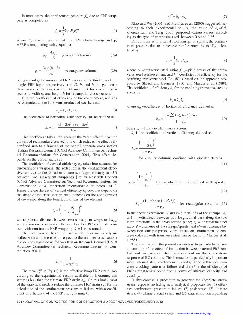
As shown in Figs. 7 and 8, stress-strain curves are assumed tobe the same for every value of 2r /b until reaching peak stress:after a first increasing branch similar to that of unconfined con-crete �since the strain is small and the confinement action, prac-tically, is not active�, another increasing branch, in whichconfinement becomes active and confining pressure increases al-most linearly, is assumed. A final decreasing branch after reachingpeak stress, until reaching maximum confinement pressure �Wangand Wu 2008� is defined for columns with 2r /b�0.3 only.
Fig. 6. Strain variation along the row of circumferential strain gauges�400 mm long� in precracking �fc=23.8 MPa� and postcracking �fc
=45.6 MPa� phase for a GFRP confined specimen with circular crosssection and internal steel reinforcement
Fig. 7. Assumed �-� diagram for columns with 2r /b�0.3
OR CONSTRUCTION © ASCE / NOVEMBER/DECEMBER 2010 / 697
tion subject to ASCE license or copyright. Visithttp://www.ascelibrary.org
In Figs. 7 and 8, and in the text, the following notation isadopted:• fc0 ,�c0=maximum stress and strain for unconfined concrete;• fcc ,�cc=peak stress and strain for confined concrete;• fcu ,�cu=ultimate stress and strain for confined concrete.
According to the above statements, peak stress and strain cor-respond to maximum FRP confinement pressure for columns with2r /b�0.3, whereas peak stress corresponds to a confinementpressure less than the maximum one, to which the ultimate strainis correlated, for columns with 2r /b�0.3.
The proposed model for generating a complete stress-strainresponse until reaching peak stress is basically the same for eachvalue of 2r /b and is based on the four-parameters bilinear modelof Richard and Abbott �1975�
� =�E0 − E1��
�1 + � �E0 − E1��f i1
�n�1/n + E1� for 0 � � � �cc �18�
The four parameters defining the stress-strain curve are thefollowing �Pantelides and Yan 2007�: E0=slope of the first branchof the curve and represents the elastic modulus of the unconfinedconcrete and E1=slope of the second branch of the curve and canbe calculated as
E1 =fcc − fc0
�cc − �c0�19�
f i1= intersection between the line corresponding to the secondbranch of the curve and the vertical axis �see Fig. 7�
f i1 = fcc − E1�cc �20�
n=parameter related to the curvature of the transition between thefirst two linear branches defined as
n = 1 +1
E0
Ec0− 1
�21�
where Ec0 represents the secant modulus related to the slope ofthe line passing from the origin and the point in which the slopechanges
Ec0 =fc0
�c0�22�
The decreasing branch, defined only for the columns with2r /b�0.3, is also linear and defined by the equation of the linepassing from the points corresponding to peak and ultimate stress
Fig. 8. Assumed �-� diagram for columns with 2r /b�0.3
�see Fig. 8�
698 / JOURNAL OF COMPOSITES FOR CONSTRUCTION © ASCE / NOVE
Downloaded 15 Nov 2010 to 147.162.29.67. Redistribu
� = E2� − f i2 for �cc � � � �cu and 2r/b � 0.3 �23�
where E2=slope of the third branch
E2 =fcu − fcc
�cu − �cc�24�
and f i2= intersection between the line corresponding to the thirdbranch and the vertical axis �Fig. 8�
f i2 =�cu · fc0 − �c0 · fcu
�c0 − �cu�25�
Peak Stress
The model for the peak stress is inspired to that of Harajli et al.�2006� and those for the confinement with transverse reinforcingsteel, in which peak stress of the confined concrete fcc is in-creased with respect to that of the unconfined concrete fco, pro-portionally to the total confining pressure at failure Pu
fcc
fco= 1 + k1 ·
Pu
fco�26�
The coefficient k1, in the present analytical model, is computedas the product of two coefficients
k1 = kA · kR �27�
The coefficient kA is computed with the same formula pro-posed by Harajli et al. �2006�
kA = A� Pu
fco�−�
�28�
but the parameters A and � are computed by means of a regres-sion analysis of the experimental data included in the above ex-perimental database and related to the columns with 2r /b�0.3only. Considering separately the coefficients for circular and rect-angular columns, with and without steel reinforcement, the valueslisted in Table 1 are proposed.
The reduction coefficient kR takes into account that, for rect-angular columns with 2r /b�0.3, confining pressure correspond-ing to peak stress is lower than that corresponding to ultimatefailure. kR is obtained as a function of 2r /b with the followingexpressions derived from a regression analysis:
kR = 1 – 2.5�0.3 − 2r/b� for 2r/b � 0.3 �29�
kR = 1 for 2r/b � 0.3 �30�
Ultimate Stress
For columns with 2r /b�0.3, the ultimate stress fcu is related tothe peak stress in relation to the ratio 2r /b. According to the
Table 1. Proposed Values of the Coefficients A and � in Eq. �15�
Circular cross section Rectangular cross section
Without steel With steel Without steel With steel
A 3.55 2.95 2.25 1.35
� 0.15 0.40 0.25 0.50
experimental results, the ratio between ultimate and peak stress
MBER/DECEMBER 2010
tion subject to ASCE license or copyright. Visithttp://www.ascelibrary.org

fcu / fcc assumes values close to 1 when 2r /b�0.3. For 2r /b�0.3 the ratio fcu / fcc can be computed with the following expres-sion derived from a regression analysis:
fcu
fcc= 0.55 + 1.5�2r/b� for 2r/b � 0.3 �31�
Ultimate Axial Strain
According to the common approach of the literature, the ratio�cu /�co is estimated as a function of the confinement pressure Pu
�cu
�co= 2 + B� Pu
fco� �32�
Table 2. Proposed Values of the Coefficient B in Eq. �19�
Circular cross section Rectangular cross section
Without steel With steel Without steel With steel
B 23 28 23 28
"#$
"&$
Fig. 9. Comparison between theoretical values calculated with the prconcrete columns �a� with circular cross section and without steel reinrectangular cross section and without steel reinforcement; and �d� wi
JOURNAL OF COMPOSITES F
Downloaded 15 Nov 2010 to 147.162.29.67. Redistribu
The choice of a simplified model for the ultimate axial strain isdue to the significant dispersion of experimental values �whichare less than those for peak stress� and the consequent difficulty toindividuate the relevant parameters on which the ultimate axialstrain depends. The parameter B is computed by means of a re-gression analysis of the experimental data included in the aboveexperimental database considering separately the coefficients forcircular and rectangular columns, with or without steel reinforce-ment. The proposed values of the parameter B are listed in Table2. At the moment, the quantity of available experimental data didnot allow to find different values of parameter B for circular andrectangular columns. Once other experimental data on ultimatestrains will be available, it will be possible to improve the valueof the parameter B and eventually find different values for circu-lar and rectangular columns. However the model provides differ-ent results, in terms of ultimate strains, for circular and prismaticcolumns since the effective confinement pressure in Eq. �32� iscalculated with different formulas for the two types of columns.
"%$
"'$
model and experimental values of the peak stress for FRP confinedent; �b� with circular cross section and steel reinforcement; �c� with
angular cross section and steel reinforcement
oposedforcemth rect
OR CONSTRUCTION © ASCE / NOVEMBER/DECEMBER 2010 / 699
tion subject to ASCE license or copyright. Visithttp://www.ascelibrary.org

Axial Strain Corresponding to Peak Stress
As for the case of peak and ultimate stresses, axial strain corre-sponding to peak stress �cc differs from the ultimate strain forFRP confined columns with 2r /b�0.3. Since there are not manyexperimental results available in literature related to axial straincorresponding to peak stress, the relation between the ratio�cc /�cu and 2r /b is assumed as the same of that proposed for theratio fcu / fcc
�cc
�cu= 0.55 + 1.5�2r/b� for 2r/b � 0.3 �33�
Evaluation of the Accuracy of the Proposed Model
An assessment of some of the actual confinement models and thenew proposals was developed comparing the theoretical values ofpeak stress and ultimate strain with the corresponding experimen-tal values, calculating the average ratio between theoretical andexperimental stress or strain �AVG� and the coefficient of varia-tion �COV�.
The models taken into consideration are those of some main
Fig. 10. Comparison between theoretical values calculated with theconfined concrete columns �a� with circular cross section and without�c� with rectangular cross section and without steel reinforcement; an
guidelines �fédération internationale du béton 2001; American
700 / JOURNAL OF COMPOSITES FOR CONSTRUCTION © ASCE / NOVE
Downloaded 15 Nov 2010 to 147.162.29.67. Redistribu
Concrete Institute 2002; Italian Research Council �CNR� Advi-sory Committee on Technical Recommendations for Construction2004�, the models of Fardis and Khalili �1981�, Ilki and Kum-basar �2003�, Lam and Teng �2003�, and Matthys et al. �2006�, inwhich the contribution of the internal steel reinforcement is notexplicitly considered, and the models of Kawashima et al. �2000�,Li et al. �2003�, Harajli et al. �2006�, Tastani et al. �2006�, and Ilkiet al. �2008�, in which the contribution of the internal steel rein-forcement is considered �but the interaction between external FRPand internal steel reinforcement is not taken into account�.
In Figs. 9�a–d� and 10�a–d�, the comparisons between theoret-ical values calculated with the proposed model and experimentalvalues of peak stress and ultimate strain are, respectively, shown.The comparisons are related to FRP confined concrete columns�1� with circular cross section and without steel reinforcement; �2�with circular cross section and steel reinforcement; �3� with rect-angular cross section and without steel reinforcement; and �4�with rectangular cross section and steel reinforcement.
In Tables 3–6, the average ratio between theoretical and ex-perimental peak stress and ultimate strain �AVG� and the COV arelisted for the above models and the new proposals. Circular andrectangular columns with and without steel reinforcement are dis-
osed model and experimental values of the ultimate strain for FRPeinforcement; �b� with circular cross section and steel reinforcement;with rectangular cross section and steel reinforcement
propsteel rd �d�
tinguished. It can be observed that the new proposal shows, for
MBER/DECEMBER 2010
tion subject to ASCE license or copyright. Visithttp://www.ascelibrary.org

the four column typologies �circular without steel reinforcement,circular with steel reinforcement, rectangular without steel rein-forcement, and rectangular with steel reinforcement� the lowestvalues of the COV and values of AVG close to 1 and slightlyconservative. It can also be observed that the recent models ofHarajli et al. �2006� and Ilki et al. �2008�, in which the contribu-tion of the internal steel reinforcement is considered �but the in-teraction between external FRP and internal steel reinforcement isnot taken into account�, generally show a rather good perfor-mance for the prediction of both peak stress and ultimate strainboth for circular and rectangular columns.
In Figs. 11 and 12 the predictions of the new Eqs. �31� for theultimate stress and Eq. �33� for the strain corresponding to peakstress are compared with the experimental results of the databasein fcu / fcc versus 2r /b and �cc /�cu versus 2r /b diagrams. It has to
Table 3. Theoretical-Experimental Comparison for FRP Confined Circul
Models for circular columns
Pe
A
fib “practical formula” �fédération internationale du béton2001�
1
ACI 440.2R-02 �American Concrete Institute 2002� 0
CNR DT200 �Italian Research Council �CNR� AdvisoryCommittee on Technical Recommendations for Construction2004�
0
Fardis and Khalili �1981� 1
Ilki and Kumbasar �2003� 0
Lam and Teng �2003� 0
Matthys et al. �2006� 1
Kawashima et al. �2000� 1
Li et al. �2003� 0
Harajli et al. �2006� 0
Tastani et al. �2006� 1
Ilki et al. �2008� 0
Proposed model 0
Table 4. Theoretical-Experimental Comparison for FRP Confined Circul
Models for circular columns
P
fib practical formula �fédération internationale du béton 2001�
ACI 440.2R-02 �American Concrete Institute 2002�
CNR DT200 �Italian Research Council �CNR� AdvisoryCommittee on Technical Recommendations for Construction2004�
Fardis and Khalili �1981�
Ilki and Kumbasar �2003�
Lam and Teng �2003�
Matthys et al. �2006�
Kawashima et al. �2000�
Li et al. �2003�
Harajli et al. �2006�
Tastani et al. �2006�
Ilki et al. �2008�
Proposed model
JOURNAL OF COMPOSITES F
Downloaded 15 Nov 2010 to 147.162.29.67. Redistribu
be observed that the number of available results is, at the moment,rather small and Eqs. �31� and �33� can be improved when newexperimental results will be available.
In Fig. 13 comparisons between analytical stress-strain curvesprovided by the proposed model and some experimental curvesobtained by Wang and Wu �2008� �specimens �a� C30-2-30, �b�C50-2-45, and �c� C50-2-0 without internal steel reinforcement�and Ilki et al. �2008� �specimens �d� LSR-C-3 and �e� LSR-R-2-2-40 with internal steel reinforcement� are shown. Analyticalcurves describe experimental behavior quite well both for col-umns with and without internal steel. The difference between thedecreasing branches in Fig. 13�c� is due to the large scatter relatedto experimental ultimate stresses when the decreasing branch oc-curs.
umns without Internal Steel Reinforcement
Columns without steel reinforcement
ss �191 specimens� Ultimate axial strain �175 specimens�
COV AVG COV
0.174 2.737 2.666
0.231 0.474 0.564
0.235 — —
0.439 1.109 0.849
0.150 1.416 0.590
0.154 0.794 0.355
0.166 1.283 0.700
0.386 0.813 0.325
0.149 0.777 0.334
0.179 0.740 0.562
0.205 — —
0.148 1.753 0.943
0.142 0.983 0.323
umns with Internal Steel Reinforcement
Columns with steel reinforcement
ress �54 specimens� Ultimate axial strain �35 specimens�
COV AVG COV
0.206 2.066 1.678
0.266 0.279 0.741
0.266 — —
0.370 0.970 0.701
0.178 1.031 0.480
0.192 0.663 0.450
0.185 1.011 0.487
0.427 0.771 0.414
0.181 0.590 0.498
0.221 0.708 0.622
0.203 — —
0.173 1.595 0.992
0.146 0.981 0.398
ar Col
ak stre
VG
.034
.811
.830
.337
.987
.941
.062
.288
.946
.952
.092
.973
.991
ar Col
eak st
AVG
0.973
0.807
0.820
1.251
0.980
0.888
1.006
1.320
0.916
0.925
1.055
0.972
0.996
OR CONSTRUCTION © ASCE / NOVEMBER/DECEMBER 2010 / 701
tion subject to ASCE license or copyright. Visithttp://www.ascelibrary.org
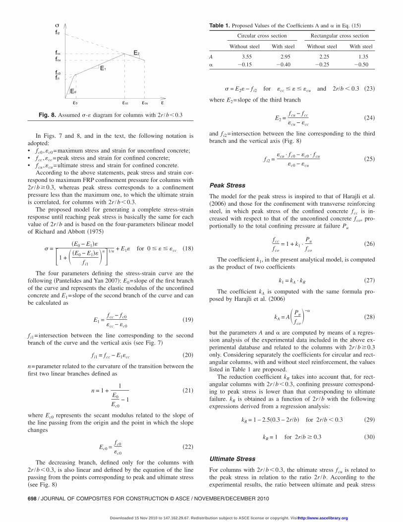
Table 5. Theoretical-Experimental Comparison for FRP Confined Rectangular Columns without Internal Steel Reinforcement
Models for rectangular columns
Columns without steel reinforcement
Peak stress �109 specimens� Ultimate axial strain �73 specimens�
AVG COV AVG COV
fib practical formula �fédération internationale du béton 2001� 0.688 0.381 0.782 0.447
ACI 440.2R-02 �American Concrete Institute 2002� 1.058 0.199 — —
CNR DT200 �Italian Research Council �CNR� AdvisoryCommittee on Technical Recommendations for Construction2004�
1.068 0.188 — —
Fardis and Khalili�1981� — — — —
Ilki and Kumbasar �2003� 1.013 0.311 1.367 0.800
Lam and Teng �2003� 0.772 0.281 1.201 0.905
Matthys et al. �2006� — — — —
Kawashima et al. �2000� 2.195 1.845 1.418 1.243
Li et al. �2003� — — — —
Harajli et al. �2006� 1.143 0.280 0.626 0.472
Tastani et al. �2006� 1.461 0.680 — —
Ilki et al. �2008� 1.309 0.544 1.984 1.266
Proposed model 0.953 0.159 0.985 0.347
Table 6. Theoretical-Experimental Comparison for FRP Confined Rectangular Columns with Internal Steel Reinforcement
Models for rectangular columns
Columns with steel reinforcement
Peak stress �121 specimens� Ultimate axial strain �41 specimens�
AVG COV AVG COV
fib practical formula �fédération internationale du béton 2001� 1.303 0.611 0.300 0.740
ACI 440.2R-02 �American Concrete Institute 2002� 0.941 0.204 — —
CNR DT200 �Italian Research Council �CNR� AdvisoryCommittee on Technical Recommendations for Construction2004�
0.959 0.202 — —
Fardis and Khalili �1981� — — — —
Ilki and Kumbasar �2003� 0.827 0.287 0.566 0.530
Lam and Teng �2003� 0.867 0.229 0.366 0.670
Matthys et al. �2006� — — — —
Kawashima et al. �2000� 2.288 1.625 0.591 0.526
Li et al. �2003� — — — —
Harajli et al. �2006� 1.017 0.207 0.323 0.729
Tastani et al. �2006� 1.234 0.378 — —
Ilki et al. �2008� 1.109 0.261 0.731 0.614
Proposed model 0.963 0.173 0.995 0.287
Fig. 11. Predictions of Eq. �31� compared with the experimentalresults in a fcu / fcc versus 2r /b diagram
702 / JOURNAL OF COMPOSITES FOR CONSTRUCTION © ASCE / NOVE
Downloaded 15 Nov 2010 to 147.162.29.67. Redistribu
Fig. 12. Predictions of Eq. �33� compared with the experimentalresults in a �cc /�cu versus 2r /b diagram
MBER/DECEMBER 2010
tion subject to ASCE license or copyright. Visithttp://www.ascelibrary.org

Fig. 13. Comparisons between the analytical stress-strain curve provided by the proposed model and some experimental curves obtained byWang and Wu �2008� �specimens �a� C30-2-30, �b� C50-2-45, and �c� C50-2-0 without internal steel reinforcement� and Ilki et al. �2008��specimens �d� LSR-C-3 and �e� LSR-R-2-2-40 with internal steel reinforcement�
JOURNAL OF COMPOSITES FOR CONSTRUCTION © ASCE / NOVEMBER/DECEMBER 2010 / 703
Downloaded 15 Nov 2010 to 147.162.29.67. Redistribution subject to ASCE license or copyright. Visithttp://www.ascelibrary.org

Conclusions
In this work, new analytical proposals for �1� effective confine-ment pressure at failure; �2� peak stress; �3� ultimate stress; �4�ultimate axial strain; and �5� axial strain corresponding to peakstress for FRP confined concrete elements with circular and rect-angular cross section, with and without internal steel reinforce-ment, are shown. According to the aforementioned analyticalproposals �1–4�, a procedure to generate the complete stress-strain response for circular and rectangular concrete columns withand without internal steel reinforcement confined with FRP is alsoproposed.
Interaction mechanisms between internal steel reinforcementand external FRP strengthening are taken into account for thecomputation of the coefficient of efficiency of the FRP, accordingto some experimental results obtained at the University of Padovawith accurate measurements. In particular, if the rigidity of theexternal FRP jacketing is not enough to contrast buckling of ver-tical steel bars, stress concentrations in the FRP can occur, caus-ing its premature failure and a reduction of efficiency of the FRPconfining technique.
According to the experimental results included in a wide da-tabase regarding FRP confined concrete columns, with circularand rectangular cross section, with and without existing steel re-inforcement, the new proposal appears to be the most accurate,compared to a number of analytical models available in literature,since it shows the lowest values of the COV and values of AVGclose to 1 and slightly conservative. Comparisons between ana-lytical stress-strain curves provided by the proposed model andexperimental curves obtained by some writers show a good agree-ment. However, further experimental results could be necessary toimprove the formulations for the ultimate stress and axial straincorresponding to peak stress.
Acknowledgments
The writers wish to thank Anna Mazzucato for the contributiondeveloped during the preparation of her degree thesis. Financialsupport from the Italian Ministry of Education and Scientific Re-search �Progetto di Ateneo 2008 cod. CPDA081713 and PRIN2007JHK33Y_003� is gratefully acknowledged.
References
American Concrete Institute. �2002�. “Guide for the design and construc-tion of externally bonded FRP systems for strengthening of concretestructure.” ACI 440.2R-02, Farmington Hill, Mich.
Arduini, M., Di Tommaso, A., Manfroni, O., Ferrari, S., and Romagnolo,M. �1999�. “Il confinamento passivo di elementi compressi in calces-truzzo con fogli di materiale composito.” L’Industria Italiana del Ce-mento, 748, 836–841 �in Italian�.
Berthet, J. F., Ferrier, E., and Hamelin, P. �2005�. “Compressive behav-iour of concrete externally confined by composite jackets. Part A:Experimental study.” Constr. Build. Mater., 19�3�, 223–232.
Braga, F., Laterza, M., Gigliotti, R., Dragonetti, G., and Nigro, D. �2004�.“Prove di compressione ciclica su pilastri in c.a. confinati con staffee/o con tessuti in fibra di carbonio.” Proc., XI National CongressL’Ingegneria sismica in Italia �ANIDIS�, ANIDIS, Genova, Italy �inItalian�.
Campione, G. �2006�. “Influence of FRP wrapping techniques on thecompressive behaviour of concrete prisms.” Cem. Concr. Compos.,
28, 497–505.704 / JOURNAL OF COMPOSITES FOR CONSTRUCTION © ASCE / NOVE
Downloaded 15 Nov 2010 to 147.162.29.67. Redistribu
Carey, S. A., and Harries, K. A. �2005�. “Axial behaviour and modelingof confined small, medium, and large-scale circular sections with car-bon fiber-reinforced polymer jackets.” ACI Struct. J., 102�4�, 596–604.
Chaallal, O., Shahawy, M., and Hassa, M. �2003�. “Performance of axi-ally loaded short rectangular columns strengthened with carbon FRPwrapping.” J. Compos. Constr., 7�3�, 200–208.
Cole, C., and Belarbi, A. �2001�. “Confinement characteristics of rectan-gular FRP-jacketed RC columns.” Proc., Fifth Int. Symp. on FiberReinforced Polymer for Reinforced Concrete Structures (FRPRCS-5).
Demers, M., and Neale, K. W. �1999�. “Confinement of reinforced con-crete columns with fibre-reinforced composite sheets-an experimentalstudy.” Can. J. Civ. Eng., 26, 226–241.
De Paula, R. F., and Da Silva, M. G. �2002�. “Sharp edge effects on FRPconfinement of RC square columns.” Proc., 3rd Int. Conf. on Com-posites in Infrastructure (ICCI’02), Hardback, Netherlands.
Esfahani, M. R., and Kianoush, M. R. �2004�. “Axial compressivestrength of reinforced concrete columns wrapped with FRP.” Proc.,1st Conf. on Application of FRP Composites in Construction andRehabilitation of Structures, Building and Housing Research Center,Tehran.
Fardis, M. N., and Khalili, H. �1981�. “Concrete encased in fibreglass-reinforced-plastic.” ACI J., 78�6�, 440–446.
Fédération internationale du béton. �2001�. “Externally bonded FRP rein-forcement for RC structures.” Bullettin no. 14, Lausanne, Switzerland.
Feng, P., Lu, X. Z., and Ye, L. P. �2002�. “Experimental research andfinite element analysis of square concrete columns confined by FRPsheets under uniaxial compression.” Proc., 17th Australian Conf. onthe Mechanics of Structures and Materials (ACMSM17), A. A.Balkema, Rotterdam, Netherlands, 71–76.
Harajli, M. H. �2006�. “Axial stress-strain relationship for FRP confinedcircular and rectangular concrete columns.” Cem. Concr. Compos.,28, 938–948.
Harajli, M. H., Hantouche, E., and Soudki, K. �2006�. “Stress-strainmodel for fiber-reinforced polymer jacketed concrete columns.” ACIStruct. J., 103�5�, 672–680.
Harmon, T. G., and Slattery, K. T. �1992�. “Advanced composite confine-ment of concrete.” Proc., 1st Int. Conf. on Advanced Composite Ma-terials in Bridges and Structures, Canadian Society for CivilEngineering, Canada, 299–306.
Harries, K. A., and Carey, S. A. �2003�. “Shape and ‘gap’ effects on thebehaviour of variably confined concrete.” Cem. Concr. Res., 33, 881–890.
Hosseini, A., and Fadaee, S. �2004�. “Behaviour of high strength squareconcrete columns strengthened with carbon fiber reinforced polymers�CFRP�.” Proc., 1st Conf. on Application of FRP Composites in Con-struction and Rehabilitation of Structures, Building and Housing Re-search Center, Tehran.
Ilki, A., and Kumbasar, N. �2003�. “Compressive behaviour of carbonfibre composite jacketed concrete with circular and non circular cross-section.” J. Earthquake Eng., 7�3�, 381–406.
Ilki, A., Peker, O., Karamuk, E., Demir, C., and Kumbasar, N. �2008�.“FRP retrofit of low and medium strength circular and rectangularreinforced concrete columns.” J. Mater. Civ. Eng., 20�2�, 169–188.
Italian Research Council �CNR� Advisory Committee on Technical Rec-ommendations for Construction. �2004�. “Guide for the design andconstruction of externally bonded FRP systems for strengthening ex-isting structures.” CNR-DT 200/2004, Rome.
Kawashima, K., Hosotani, M., and Yoneda, K. �2000�. “Carbon fibersheet retrofit of reinforced concrete bridge piers.” Proc., Int. Work-shop on Annual Commemoration of Chi-Chi Earthquake, Vol. II, Na-tional Center for Research on Earthquake Engineering, Taipei,Taiwan, 124–135.
Kono, S., Inazumi, M., and Kaku, T. �1998�. “Evaluation of confiningeffects of CFRP sheets on reinforced concrete members.” Proc., 2ndInt. Conf. on Composites in Infrastructure ICCI’98, Univ. of Arizona,
Tucson, 343–355.MBER/DECEMBER 2010
tion subject to ASCE license or copyright. Visithttp://www.ascelibrary.org

Lam, L., and Teng, J. G. �2003�. “Design-oriented stress-strain model forFRP-confined concrete.” Constr. Build. Mater., 17, 471–489.
Li, Y., Fang, T., and Chern, C. �2003�. “A constitutive model for concretecylinder confined by steel reinforcement and carbon fibre sheet.”Proc., Pacific Conf. on Earthquake Engineering, Univ. of Canterbury,Christchurch, New Zealand.
Lin, J. L., and Liao, C. I. �2004�. “Compressive strength of reinforcedconcrete column confined by composite material.” Compos. Struct.,65, 239–250.
Maalej, M., Tanwongsval, S., and Paramasivam, P. �2003�. “Modelling ofrectangular columns strengthened with FRP.” Cem. Concr. Compos.,25, 263–276.
Mander, J. B., Priestley, M. J. N., and Park, R. �1988�. “Theoreticalstress-strain model for confined concrete.” J. Struct. Eng., 114�8�,1804–1826.
Matthys, S., Taerwe, L., and Audenaert, K. �1999�. “Tests on axiallyloaded concrete columns confined by fiber reinforced polymer sheetwrapping.” Proc., 4th Int. Symp. on Fiber Reinforced Polymer Rein-forcement for Reinforced Concrete Structures, 217–228.
Matthys, S., Toutanji, H., Audenaert, K., and Taerwe, L. �2005�. “Axialload behaviour of large-scale columns confined with fiber-reinforcedpolymer composites.” ACI Struct. J., 102�2�, 258–267.
Matthys, S., Toutanji, H., and Taerwe, L. �2006�. “Stress-strain behaviourof large-scale circular columns confined with FRP composites.” J.Struct. Eng., 132�1�, 123–133.
Micelli, F., Myers, J. J., and Murthy, S. �2001�. “Effect of environmentalcycles on concrete cylinders confined with FRP.” Proc., CCC2001Int. Conf. on Composites in Construction, Univ. of Porto, Porto, Por-tugal.
Mirmiran, A., Shahawy, M., Samaan, M., El Echary, H., Mastrapa, J. C.,and Pico, O. �1998�. “Effect of column parameters on FRP-confinedconcrete.” J. Compos. Constr., 2�4�, 175–185.
Miyauchi, K., Nishibayashi, S., and Inoue, S. �1997�. “Estimation ofstrengthening effects with carbon fiber sheet for concrete column.”Proc., 3rd Int. Symp. (FRPRCS-3) on Non-Metallic (FRP) Reinforce-ment for Concrete Structures, Japan Concrete Institute, Tokyo, 217–224.
Mukherjee, A., Boothby, T. E., Bakis, C. E., Joshi, M. V., and Maitra, S.R. �2004�. “Mechanical behaviour of fiber reinforced polymer-wrapped concrete columns-complicating effects.” J. Compos. Constr.,8�2�, 97–103.
Pantelides, C. P., and Yan, Z. �2007�. “Confinement model of concretewith externally bonded FRP jackets or post-tensioned FRP shells.” J.Struct. Eng., 133�9�, 1288–1296.
Parretti, R., and Nanni, A. �2002�. “Axial testing of concrete columnsconfined with carbon FRP: effect of fiber orientation.” Proc. ICCI2002, Hardback, Netherlands.
Parvin, A., and Wang, W. �2002�. “Concrete columns confined by fibercomposite wraps under combined axial and cyclic lateral loads.”Compos. Struct., 58, 539–549.
Pellegrino, C., and Modena, C. �2002�. “FRP shear strengthening of RCbeams with transverse steel reinforcement.” J. Compos. Constr., 6�2�,104–111.
Pellegrino, C., and Modena, C. �2006�. “FRP shear strengthening of RCbeams: experimental study and analytical modelling.” ACI Struct. J.,103�5�, 720–728.
Pellegrino, C., and Modena, C. �2008�. “An experimentally based ana-lytical model for shear capacity of FRP strengthened reinforced con-crete beams.” Mech. Compos. Mater. Struct., 44�3�, 231–244.
Pellegrino, C., Tinazzi, D., and Modena, C. �2004�. “Sul confinamento dielementi in c.a. soggetti a compressione.” Proc., AICAP NationalCongress, Patron, Bologna, Italy, 26–29 �in Italian�.
JOURNAL OF COMPOSITES F
Downloaded 15 Nov 2010 to 147.162.29.67. Redistribu
Pessiki, S., Harries, K. A., Kestner, J. T., Sause, R., and Ricles, J. M.�2001�. “Axial behaviour of reinforced concrete columns confinedwith FRP jackets.” J. Compos. Constr., 5�4�, 237–245.
Picher, F., Rochette, P., and Laboissiére, P. �1996�. “Confinement of con-crete cylinders with CFRP.” Proc., 1st Conf. on Composites in Infra-structure ICCI ’96, Univ. of Arizona, Tucson, 829–841.
Prota, A., Manfredi, G., and Cosenza, E. �2006�. “Ultimate behaviour ofaxially loaded RC wall-like columns confined with GFRP.” Compos-ites, Part B, 37, 670–678.
Richard, R. M., and Abbott, B. J. �1975�. “Versatile elastic-plastic stress-strain formula.” J. Engrg. Mech. Div., 101�4�, 511–515.
Rochette, P., and Labossiére, P. �2000�. “Axial testing of rectangular col-umn models confined with composites.” J. Compos. Constr., 4�3�,129–136.
Rodrigues, C. C., and Silva, M. �2001�. “Experimental investigation ofCFRP reinforced concrete columns under uniaxial cyclic compres-sion.” Proc., Fifth Symp. on Fiber Reinforced Polymer Reinforcementfor Reinforced Concrete structures (FRPRCS5), Telford, London,783–791.
Rousakis, T. �2001�. “Experimental investigation of concrete cylindersconfined by carbon FRP sheets, under monotonic and cyclic axialcompressive load.” Research Rep., Chalmers Univ. of Technology,Göteborg, Sweden.
Rousakis, T. C., Karabinis, A. I., and Kiosis, P. D. �2007�. “FRP-confinedconcrete members: Axial compression experiments and plasticitymodelling.” Eng. Struct., 29�7�, 1343–1353.
Shahawy, M., Mirmiran, A., and Beitelmann, T. �2000�. “Tests on mod-elling of carbon-wrapped concrete columns.” Composites, Part B, 31,471–480.
Sheikh, S. A., and Uzumeri, S. M. �1980�. “Strength and ductility of tiedconcrete columns.” J. Struct. Div., 106�5�, 1079–1102.
Silva, M. A. G., and Rodrigues, C. C. �2006�. “Size and relative stiffnesseffects on compressive failure of concrete columns wrapped withglass FRP.” J. Mater. Civ. Eng., 18�3�, 334–342.
Tan, K. H. �2001�. “Strength enhancement of rectangular reinforced con-crete columns using fiber reinforced polymer.” J. Compos. Constr.,6�3�, 175–183.
Tastani, S. P., Pantazopoulou, S. J., Zdoumba, D., Plakantaras, V., andAkritidis, E. �2006�. “Limitations of FRP jacketing in confining old-type reinforced concrete members in axial compression.” J. Compos.Constr., 10�1�, 13–25.
Teng, J. G., and Lam, L. �2004�. “Behaviour and modeling of fiber rein-forced polymer-confined concrete.” J. Struct. Eng., 130�11�, 1713–1723.
Tinazzi, D., Pellegrino, C., Cadelli, G., Barbato, M., Modena, C., andGottardo, R. �2003�. “An experimental study of RC columns confinedwith FRP sheets.” Proc., Structural Faults and Repair, 10th Int. Conf.,Engineering Technics Press, Edinburgh, Scotland.
Toutanji, H. �1999�. “Stress-strain characteristics of concrete columnsexternally confined with advanced fiber composite sheets.” ACIMater. J., 96�3�, 397–404.
Wang, L. M., and Wu, Y. F. �2008�. “Effect of corner radius on theperformance of CFRP-confined square concrete columns: Test.” Eng.Struct., 30�2�, 493–505.
Watanabe, K., et al. �1997�. “Confinement effect of FRP sheet on strengthand ductility of concrete cylinders under uniaxial compression.”Proc., 3rd Int. Symp. (FRPRCS-3) on Non-Metallic (FRP) Reinforce-ment for Concrete Structures, Japan Concrete Institute, Tokyo, 233–240.
Xiao, Y., and Wu, H. �2000�. “Compressive bahaviour of concrete con-fined by carbon fiber composite jackets.” J. Mater. Civ. Eng., 12�2�,139–146.
OR CONSTRUCTION © ASCE / NOVEMBER/DECEMBER 2010 / 705
tion subject to ASCE license or copyright. Visithttp://www.ascelibrary.org
Related Documents