IEEE TRANSACTIONS ON MAGNETICS, VOL. X, NO. X, X 2012 1 Analytical Approach for Air-gap Modeling of Field-Excited Flux-Switching machine: No-load Operation Benjamin Gaussens 12 , Student Member, IEEE, Emmanuel Hoang 1 , Olivier de la Barri` ere 1 , Jacques Saint-Michel 2 , Michel L´ ecrivain 1 , and Mohamed Gabsi 1 , Member, IEEE 1 SATIE, ENS Cachan, CNRS, UniverSud, 61 av. du President Wilson, Cachan F-94230, France 2 Leroy Somer, Emerson, EPG Division, Sillac, Bd Marcellin Leroy - 16015 Angoulˆ eme Cedex, France This paper presents a general and accurate approach to determine the no-load flux of field-excited flux-switching (FE-FS) machines. These structures are inherently difficult to model due to their doubly-slotted air-gap. This analytical approach is based on MMF-permeance theory. The analytical model developed is extensively compared to field distribution obtained with 2D Finite Element (2D FE) Simulations. The good agreement observed between analytical model and 2D FE results emphasizes the interest of this general approach regarding the computation time. Hence, this analytical approach is suitable for optimization process in pre- sizing loop. Furthermore, based on the field model, classical electromagnetic performances can be derived, such as flux-linkage and back-electromotive force (back-EMF) and also, unbalanced magnetic force. Once again, FE results validate the analytical prediction, allowing investigations on several stator-rotor combinations, or optimization of the back-EMF. Index Terms—Analytical model, magnetic field, switched flux, flux-switching, slotting effect, air-gap permeance, modified magnetomotive force. I. I NTRODUCTION F LUX-Switching (FS) machines have attracted consider- able attention in recent years, especially topologies using permanent magnet (Permanent Magnet Flux-Switching PM-FS machines). To the author’s knowledge, a single-phase flux- switching alternator was firstly described in the 50’s [1]. A single phase and a three phase flux-switching topologies were further studied in [2][3], where bipolar flux principle has been revealed. Since then, extensive work was proposed notably in United-Kingdom [4][5][6], in Japan [7] and in France [8][9][10]. Their large torque capability with practi- cally sinusoidal back-electromotive force (EMF) makes them really interesting. Also, their robust structure, with a passive rotor and all active parts located in the stator allows brushless operation with reduced maintenance. For all these reasons, the PM-FS machine appears to be eligible for many industrial applications. However, the difficult flux control capability in PM excited topologies is in contradiction with wide speed operation (con- stant power region), though, Hybrid-Excited Flux-Switching (HE-FS) machines were proposed combining the effect of per- manent magnet with an additional DC-coil allowing good flux regulation. They have been analyzed extensively particularly in terms of their potential to extend the flux-weakening range of permanent magnet machines and to improve efficiency [11]. In the literature different HE-FS topologies are listed. Some of them can be classified as serie flux path HE-FS machine [12][13] and others as parallel flux path HE-FS machine [14]. Finally, Field-Excited Flux-Switching (FE-FS) machines Manuscript received February 17, 2012; revised April 16, 2012; ac- cepted April 18, 2012. Corresponding author: B. Gaussens (e-mail: [email protected]). Color versions of one or more of the figures in this paper are available online at http://ieeexplore.ieee.org. Digital Object Identifier ... were proposed. Few investigations were undertaken but every- body agree that this topology is particularly attractive for low cost-operation [15][16][17]. With a fully controllable flux, FE- FS machines are similar to wound field synchronous machines except that they have inherent static excitation, i.e., without brushes. Fig. 1 shows an elementary cell of classical FE-FS machines. It can be seen that this topology has overlapping windings, which will result in a higher copper consumption. To overcome this problem, authors of [18][19] proposed an innovative topology, still based on flux-switching principle, but with modular rotor and non-overlapping windings. In this paper, the focus will be on classical FE-FS machine. A. Principle of Operation The flux-switching principle is briefly reminded in Fig. 1. Similar to the classical PM-FS machine, in the FE-FS machine, the negative and positive maximum flux-linkage of coil A1 occurs when a rotor pole is approximately aligned with one of the stator teeth (Figs. 1.(a) and (b)). Therefore, a movement of the rotor induce a bipolar flux- linkage and hence, an alternating back-EMF (Fig. 1.(c)). In the literature a significant number of publications are proposing analytical modeling of the slot effect on the air-gap magnetic field. An accurate model to account for the slot influence is of first interest here, since saliency in these machines is directly related to the operating principle. In the first part of this article, we propose an original and low time-consuming analytical approach for modeling the doubly-salient air-gap. B. Modeling of the Flux-Switching Machine in the Literature As specified beforehand, the wealth of literature on FS machines has hardly addressed the issue of FE-FS topologies. The majority of papers were dedicated to PM-FS structures. Usually, numerical techniques such as finite element methods

Welcome message from author
This document is posted to help you gain knowledge. Please leave a comment to let me know what you think about it! Share it to your friends and learn new things together.
Transcript
IEEE TRANSACTIONS ON MAGNETICS, VOL. X, NO. X, X 2012 1
Analytical Approach for Air-gap Modeling of Field-ExcitedFlux-Switching machine: No-load Operation
Benjamin Gaussens12, Student Member, IEEE, Emmanuel Hoang1, Olivier de la Barriere1,Jacques Saint-Michel2, Michel Lecrivain1, and Mohamed Gabsi1, Member, IEEE
1 SATIE, ENS Cachan, CNRS, UniverSud, 61 av. du President Wilson, Cachan F-94230, France2Leroy Somer, Emerson, EPG Division, Sillac, Bd Marcellin Leroy - 16015 Angouleme Cedex, France
This paper presents a general and accurate approach to determine the no-load flux of field-excited flux-switching (FE-FS)machines. These structures are inherently difficult to model due to their doubly-slotted air-gap. This analytical approach is basedon MMF-permeance theory. The analytical model developed isextensively compared to field distribution obtained with 2DFiniteElement (2D FE) Simulations. The good agreement observed between analytical model and 2D FE results emphasizes the interest ofthis general approach regarding the computation time. Hence, this analytical approach is suitable for optimization process in pre-sizing loop. Furthermore, based on the field model, classical electromagnetic performances can be derived, such as flux-linkage andback-electromotive force (back-EMF) and also, unbalancedmagnetic force. Once again, FE results validate the analytical prediction,allowing investigations on several stator-rotor combinations, or optimization of the back-EMF.
Index Terms—Analytical model, magnetic field, switched flux, flux-switching, slotting effect, air-gap permeance, modifiedmagnetomotive force.
I. I NTRODUCTION
FLUX-Switching (FS) machines have attracted consider-able attention in recent years, especially topologies using
permanent magnet (Permanent Magnet Flux-Switching PM-FSmachines). To the author’s knowledge, a single-phase flux-switching alternator was firstly described in the 50’s [1].A single phase and a three phase flux-switching topologieswere further studied in [2][3], where bipolar flux principlehas been revealed. Since then, extensive work was proposednotably in United-Kingdom [4][5][6], in Japan [7] and inFrance [8][9][10]. Their large torque capability with practi-cally sinusoidal back-electromotive force (EMF) makes themreally interesting. Also, their robust structure, with a passiverotor and all active parts located in the stator allows brushlessoperation with reduced maintenance. For all these reasons,the PM-FS machine appears to be eligible for many industrialapplications.
However, the difficult flux control capability in PM excitedtopologies is in contradiction with wide speed operation (con-stant power region), though, Hybrid-Excited Flux-Switching(HE-FS) machines were proposed combining the effect of per-manent magnet with an additional DC-coil allowing good fluxregulation. They have been analyzed extensively particularlyin terms of their potential to extend the flux-weakening rangeof permanent magnet machines and to improve efficiency [11].In the literature different HE-FS topologies are listed. Someof them can be classified as serie flux path HE-FS machine[12][13] and others as parallel flux path HE-FS machine [14].
Finally, Field-Excited Flux-Switching (FE-FS) machines
Manuscript received February 17, 2012; revised April 16, 2012; ac-cepted April 18, 2012. Corresponding author: B. Gaussens (e-mail:[email protected]).
Color versions of one or more of the figures in this paper are availableonline at http://ieeexplore.ieee.org.
Digital Object Identifier ...
were proposed. Few investigations were undertaken but every-body agree that this topology is particularly attractive for lowcost-operation [15][16][17]. With a fully controllable flux, FE-FS machines are similar to wound field synchronous machinesexcept that they have inherent static excitation,i.e., withoutbrushes. Fig. 1 shows an elementary cell of classical FE-FSmachines. It can be seen that this topology has overlappingwindings, which will result in a higher copper consumption.To overcome this problem, authors of [18][19] proposed aninnovative topology, still based on flux-switching principle,but with modular rotor and non-overlapping windings. In thispaper, the focus will be on classical FE-FS machine.
A. Principle of Operation
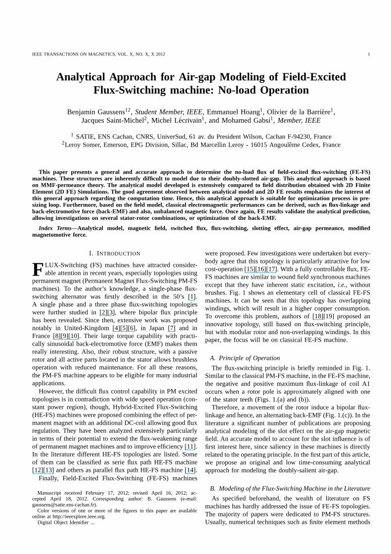
The flux-switching principle is briefly reminded in Fig. 1.Similar to the classical PM-FS machine, in the FE-FS machine,the negative and positive maximum flux-linkage of coil A1occurs when a rotor pole is approximately aligned with oneof the stator teeth (Figs. 1.(a) and (b)).
Therefore, a movement of the rotor induce a bipolar flux-linkage and hence, an alternating back-EMF (Fig. 1.(c)). Intheliterature a significant number of publications are proposinganalytical modeling of the slot effect on the air-gap magneticfield. An accurate model to account for the slot influence is offirst interest here, since saliency in these machines is directlyrelated to the operating principle. In the first part of this article,we propose an original and low time-consuming analyticalapproach for modeling the doubly-salient air-gap.
B. Modeling of the Flux-Switching Machine in the Literature
As specified beforehand, the wealth of literature on FSmachines has hardly addressed the issue of FE-FS topologies.The majority of papers were dedicated to PM-FS structures.Usually, numerical techniques such as finite element methods
2 IEEE TRANSACTIONS ON MAGNETICS, VOL. X, NO. X, X 2012
E+A+ A-
Stator
Rotor
q
(a)
E+A+ A-
(b)
0 10 20 30 40 50 60−0.02
−0.015
−0.01
−0.005
0
0.005
0.01
0.015
0.02
Position θ (mm)
Flu
x-lin
kage
ϕa
(mW
b)
Phase A
(c)
Fig. 1. Flux distribution in stator teeth with field excitation (Region E+)only: (a) Maximum flux-linkage position, (b) minimum flux-linkage positionof coil A and (c) evolution of flux-linkage as function of rotor position θ
are preferred to predict their electromagnetic performance,especially to take into account the non-linearity of magneticmaterials [20][21]. Thanks to this approach, it is possibletopredict fairly high saturation point observed in the air-gap or inthe tooth core due to high field concentration effect. However,this approach is time-consuming particularly for initial sizingof an electrical machine. Hence, the development of an analyt-ical model for initial performances calculations appears to beboth challenging and meet a real design requirement. With thewider acceptance of genetic algorithms, optimization methodscan be applied using the aforementioned analytical method.Some work of interest was proposed to model PM excitedFS machine: Zhuet al. [22] have developed a non-linearMagnetic Equivalent Circuit (MEC) model, while authors of[23] solved the governing field-equations (Laplace and quasi-Poisson equations) in the air-gap by means of Fourier analysis.The same authors have developed an interesting hybrid model[24] combining the advantages of the MEC model and Fourieranalysis. As far as we know, analytical modeling of FE-FSmachine has not yet been addressed.
In this paper, an analytical approach based onMagnetomotive-Force (MMF) and air-gap permeancedistribution, for multi-phase FE-FS machine having anypole and slot number, will be presented. A doubly-salientair-gap permeance calculation is proposed. Only internalrotor topologies are considered for the sake of clarity.However, the model could be easily extended to external rotorconfigurations. The air-gap field distribution for differentstator-rotor pole configurations, the phase flux-linkage, viz.the back-EMF and also unbalanced magnetic forces (UMF)are obtained using the model. Extensive FE simulations wereperformed to validate the approach.
II. A NALYTICAL APPROACH FOR MODELING
FIELD-EXCITED FLUX -SWITCHING MACHINE
As was mentioned before, the analytical approach is basedon MMF-permeance theory. Some assumptions are made inorder to simplify the problem:
• Classically, the rotor and stator core have infinite perme-ability, hence, the magnetic saturation is not considered.
• Non-conductive materials (No eddy currents) and 2Dproblem (end effects are neglected).
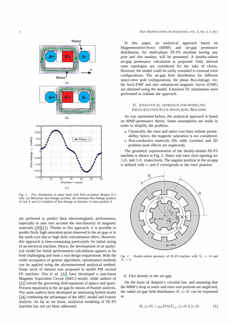
The geometric representation of the doubly-slotted FE-FSmachine is shown in Fig. 2. Stator and rotor slots opening areβsθs andβrθr respectively. The angular position in the air-gapis defined withν, andθ corresponds to the rotor position.
m®¥
Rsi
Re
Rre
q
m®¥
n
b qr r
qr
qs
b qs s
Fig. 2. Doubly-salient geometry of FE-FS machine withNs = 10 andNr = 8
A. Flux density in the air-gap
On the basis of Ampere’s circuital law, and assuming thatthe MMF’s drop in stator and rotor iron portions are neglected,the radial air-gap field distributionBr (ν, θ) can be expressedas
Br (ν, θ) = µ0MMFexc (ν, θ) Λ (ν, θ) (1)
GAUSSENSet al.: ANALYTICAL APPROACH FOR AIR-GAP MODELING OF FIELD-EXCITED FLUX-SWITCHING MACHINE: NO-LOAD OPERATION 3
In accordance with (1), we require the doubly-slotted air-gappermeanceΛ (ν, θ) and the MMF created by current-carryingconductors distributed in the stator slotsMMFexc (ν, θ).Fourier series expansions of both quantities are proposed inthe next paragraphs.
B. Magnetomotive Force created by DC-winding
The MMF distribution created by excitation coils is shownin Fig. 3 and can be defined as a function by parts over[
0, 8πNs
]
:
MMFexc (ν) =
nsIexc
βsθsν , ∀ν ∈
[
0, βsθs2
]
nsIexc
2 , ∀ν ∈[
βsθs2 , θs
(
2− βs
2
)]
−nsIexc
βsθs(ν − 2θs) , ∀ν ∈
[
θs
(
2− βs
2
)
, θs
(
2 + βs
2
)]
−nsIexc
2 , ∀ν ∈[
θs
(
2 + βs
2
)
, θs
(
4− βs
2
)]
nsIexc
βsθs(ν − 4θs) , ∀ν ∈
[
θs
(
4− βs
2
)
, 4θs
]
(2)
Every DC coil is wound around two stator teeth, so thestator tooth numberNs must be even. In [15], different waysof connecting field conductors are proposed. However, sinceend-effects are neglected (2D problem), connections of DCcoils do not impact electromagnetic performances. Expanding(2) into Fourier series over
[
0, 8πNs
]
yields to
MMFexc (ν) ∼+∞∑
n=1,3,5...
bn sin
(
nNs
4ν
)
(3)
where
bn =2
T
4θs∫
0
MMFexc (ν) sin
(
nNs
4ν
)
dν
=8nsIexc
βs (nπ)2 sin
(
nβsπ
4
)
(4)
This formula is valid for any configuration (number of phaseq or stator tooth numberNs) considered.
ν
MMFexc
Stator
0
βs sθ
θs3θs 5θs
n Is exc
2
7θs
+ +- -
DC field coils
-n Is exc
2
Fig. 3. The Magnetomotive Force created by the DC field coilsMMFexc(ν, nsIexc, βs, θs)
C. Doubly-slotted air-gap permeance function
The slotting effect, which refers to a variation of reluctancearound the periphery of the air-gap, has long been investi-gated in many papers. Two analytical approaches are mainlyconsidered in the literature.
Some models consider relative permeance functions tomodulate the radial flux calculated for a slotless motor.Conformal transformation can be employed to evaluate thisrelative permeance function [25]. One century ago, F.W. Carterused conformal mapping to derive the well-known Carter’scoefficient [26]. Also, in 1993, a series of papers dealing withanalytical modeling of brushless DC PM motors accounted forthe slotting effect using a conformal transformation method[27]. It is worth mentioning that in the work [28][29] acomplex relative permeance function was developed. By fullyexploring conformal transformation properties, authors canalso determine the tangential field in the air-gap. The relativeair-gap permeance can also be predicted considering idealizedflux lines under the slot [30][31][32]. The second approachconsists of solving the Laplace/quasi-Poissonian equation indifferent sub-domains [33][34] [35][36].
In this work, the first approach is considered, and a per-meance function based on the mean flux path under the slotopening is proposed.
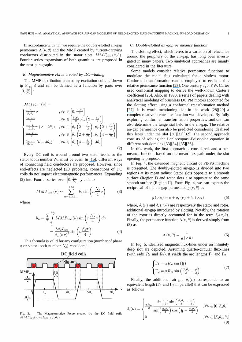
In Fig. 4, the extended magnetic circuit of FE-FS machineis presented. The doubly-slotted air-gap is divided into tworegions at its mean radius: Stator slots opposite to a smoothsurface (Region I) and rotor slots also opposite to the samesmooth surface (Region II). From Fig. 4, we can express thereciprocal of the air-gap permeanceg (ν, θ) as
g (ν, θ) = e+ δs (ν) + δr (ν, θ) (5)
where,δs(ν) andδr(ν, θ) are respectively the stator and rotor,additional air-gap introduced by slotting. Notably, the rotationof the rotor is directly accounted for in the termδr(ν, θ).Finally, the permeance functionΛ(ν, θ) is derived simply from(5) as
Λ (ν, θ) =1
g (ν, θ)(6)
In Fig. 5, idealized magnetic flux-lines under an infinitelydeep slot are depicted. Assuming quarter-circular flux-lines(with radii R1 andR2), it yields the arc lengthsΓ1 andΓ2
Γ1 = πRsi sin(
ν2
)
Γ2 = πRsi sin(
βsθs2 − ν
2
) (7)
Finally, the additional air-gapδs(ν) corresponds to anequivalent length (Γ1 andΓ2 in parallel) that can be expressedas follows
δs(ν) =
πRsi
2
sin(
ν2
)
sin(
βsθs2 − ν
2
)
sin(
βsθs4
)
cos(
ν2 − βsθs
4
) , ∀ν ∈ [0, βsθs]
0 , ∀ν ∈ [βsθs, θs]
(8)
4 IEEE TRANSACTIONS ON MAGNETICS, VOL. X, NO. X, X 2012
ν
r
Stator
Rotor
0
Region I
Region IIRre
Re
Rsi
e
δ νs( )
δ ν,θr( )
θ
Fig. 4. The extended magnetic circuit of the FE-FS machine inpseudopolar coordinate to evaluate the air-gap permeanceΛ(ν, θ)
Re
Rsi
r
νR
2R
1
Γ1 Γ2
Fig. 5. Magnetic flux-path under an infinitely deep slot
with Rsi the internal radius of stator.After linearization, and by using Fourier series expansion
of (8), it gives for the stator
δs(ν) ∼ a(I)0 +
+∞∑
n=1
a(I)n cos (nNsν) + b(I)n sin (nNsν) (9)
wherea(I)0 , a(I)n andb(I)n are
a(I)0 =
1
T
θs∫
0
δs(ν)dν
=Rsi (πβs)
2
6Ns
(10)
a(I)n =2
T
θs∫
0
δs(ν) cos (nNsν) dν
= −Rsi
2Nsn2
(1 + cos (2πnβs))−1
πnβs
sin (2πnβs)
(11)
b(I)n =2
T
θs∫
0
δs(ν) sin (nNsν) dν
=Rsi
2Nsn2
1
πnβs
(1− cos (2πnβs))− sin (2πnβs)
(12)
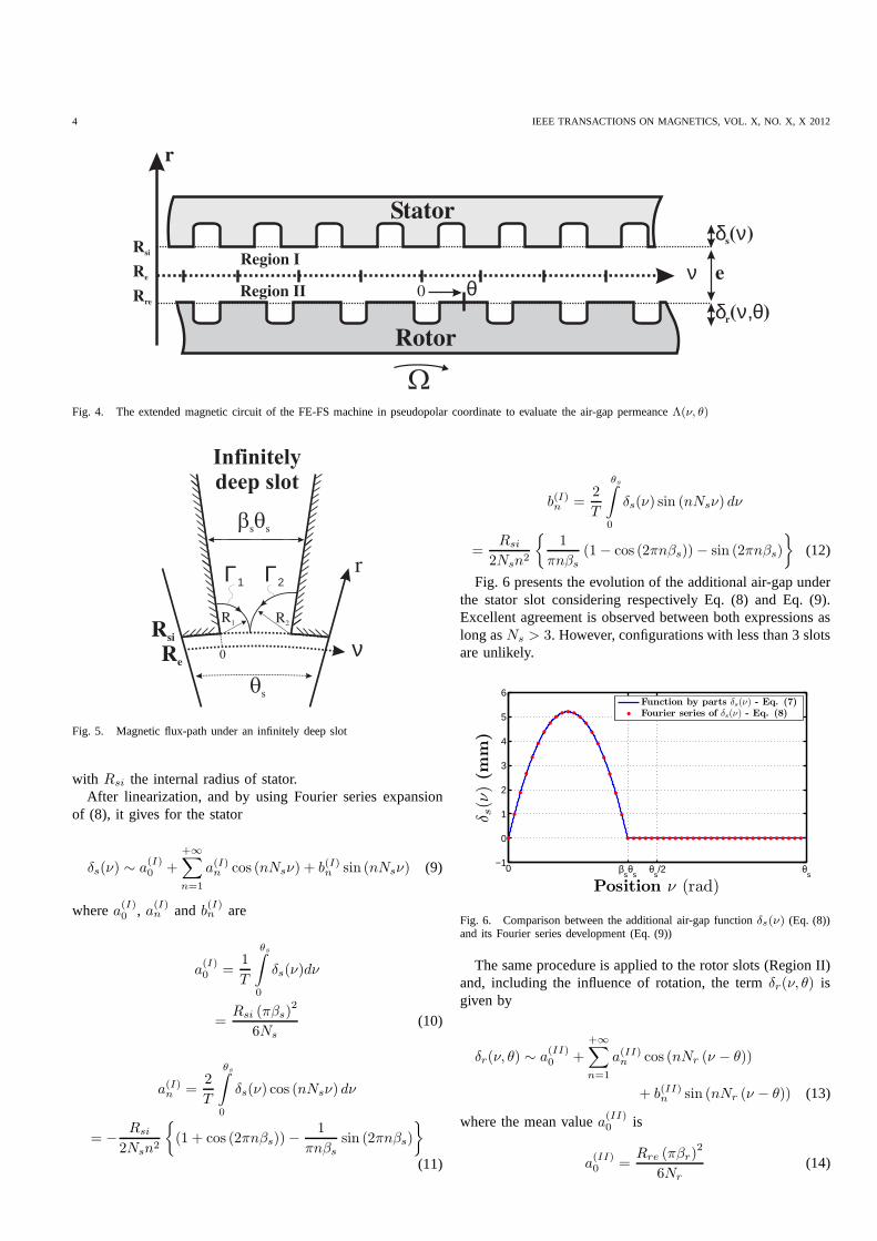
Fig. 6 presents the evolution of the additional air-gap underthe stator slot considering respectively Eq. (8) and Eq. (9).Excellent agreement is observed between both expressions aslong asNs > 3. However, configurations with less than 3 slotsare unlikely.
−1
0
1
2
3
4
5
6
Position ν (rad)
δ s(ν
)(m
m)
0 βsθ
sθ
s/2 θ
s
Function by parts δs(ν) - Eq. (7)Fourier series of δs(ν) - Eq. (8)
Fig. 6. Comparison between the additional air-gap functionδs(ν) (Eq. (8))and its Fourier series development (Eq. (9))
The same procedure is applied to the rotor slots (Region II)and, including the influence of rotation, the termδr(ν, θ) isgiven by
δr(ν, θ) ∼ a(II)0 +
+∞∑
n=1
a(II)n cos (nNr (ν − θ))
+ b(II)n sin (nNr (ν − θ)) (13)
where the mean valuea(II)0 is
a(II)0 =
Rre (πβr)2
6Nr
(14)
GAUSSENSet al.: ANALYTICAL APPROACH FOR AIR-GAP MODELING OF FIELD-EXCITED FLUX-SWITCHING MACHINE: NO-LOAD OPERATION 5
with Rre the internal rotor radius. Like (11) and (12) , theFourier coefficients are found to be
a(II)n = −Rre
2Nrn2
(1 + cos (2πnβr))−1
πnβr
sin (2πnβr)
(15)and
b(II)n =Rre
2Nrn2
1
πnβr
(1− cos (2πnβr))− sin (2πnβr)
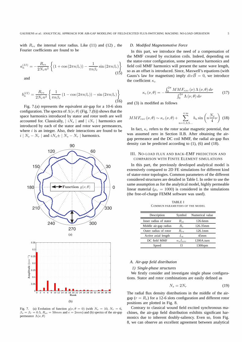
(16)Fig. 7.(a) represents the equivalent air-gap for a 10-6 slots
configuration. The spectra ofΛ(ν, θ) (Fig. 7.(b)) shows that thespace harmonics introduced by stator and rotor teeth are wellaccounted for. Classically,| iNs | and | iNr | harmonics areintroduced by each of the stator and rotor wave permeances,wherei is an integer. Also, their interactions are found to bei | Ns −Nr | and iNs± | Ns −Nr | harmonics.
(a)
0 2 4 6 8 10 12 14 16 18 20 22 24 26 28 30 32 34 36 38 400
0.05
0.1
0.15
0.2
0.25
0.3
0.35
Rank
Am
plitu
de
(mm
−1)
(b)
Fig. 7. (a) Evolution of functiong(ν, θ = 0) (with Ns = 10, Nr = 6,βs = βr = 0.5, Rsi = 50mm ande = 2mm) and (b) spectra of the air-gappermeanceΛ(ν, θ)
D. Modified Magnetomotive Force
In this part, we introduce the need of a compensation ofthe MMF created by excitation coils. Indeed, depending onthe stator-rotor configuration, some permeance harmonics andfield coil MMF harmonics will present the same wave length,so as an offset is introduced. Since, Maxwell’s equations (withGauss’s law for magnetism) implydiv ~B = 0, we introducethe coefficientκc
κc (ν, θ) = −
∫ 2π
0MMFexc (ν) Λ (ν, θ) dν
∫ 2π
0 Λ (ν, θ) dν(17)
and (3) is modified as follows
MMFexc (ν, θ) ∼ κc (ν, θ)+
+∞∑
n=1,3,5...
bn sin
(
nNs
4ν
)
(18)
In fact, κc refers to the rotor scalar magnetic potential, thatwas assumed zero in Section II.B. After obtaining the air-gap permeance and the DC coil MMF, the radial air-gap fluxdensity can be predicted according to (1), (6) and (18).
III. N O-LOAD FLUX AND BACK -EMF PREDICTION AND
COMPARISON WITHFINITE ELEMENT SIMULATIONS
In this part, the previously developed analytical model isextensively compared to 2D FE simulations for different kindof stator-rotor topologies. Common parameters of the differentconsidered structures are detailed in Table I. In order to use thesame assumption as for the analytical model, highly permeablelinear material (µr = 1000) is considered in the simulations(the free-of-charge FEMM software was used).
TABLE ICOMMUN PARAMETERS OF THE MODEL
Description Symbol Numerical value
Inner radius of stator Rsi 126.6mm
Middle air-gap radius Re 126.35mm
Outer radius of rotor Rre 126.1mm
Active axial length La 45mm
DC field MMF nsIexc 1200A.turn
Speed Ω 1300rpm
A. Air-gap field distribution
1) Single-phase structuresWe firstly consider and investigate single phase configura-
tions. Stator and rotor combinations are easily defined as
Ns = 2Nr (19)
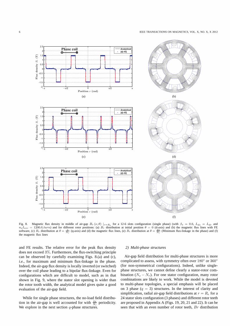
The radial flux density distributions in the middle of the air-gap (r = Re) for a 12-6 slots configuration and different rotorpositions are plotted in Fig. 8.
Contrary to classical wound field excited synchronous ma-chines, the air-gap field distribution exhibits significanthar-monics due to inherent doubly-saliency. Even so, from Fig.8, we can observe an excellent agreement between analytical
6 IEEE TRANSACTIONS ON MAGNETICS, VOL. X, NO. X, X 2012
Phase coil
(a) (b)
Phase coil
(c) (d)
Phase coil
(e) (f)
Fig. 8. Magnetic flux density in middle of air-gapBr (ν, θ) |r=Refor a 12-6 slots configuration (single phase) (withβs = 0.6, Lds = Ldr and
nsIexc = 1200A.turn) and for different rotor positions: (a)Br distribution at initial positionθ = 0 (d-axis) and (b) the magnetic flux lines with FEsoftware, (c)Br distribution atθ = π
Nr(q-axis) and (d) the magnetic flux lines, (e)Br distribution atθ = 2π
Nr(Minimum flux-linkage in the phase) and (f)
the magnetic flux lines
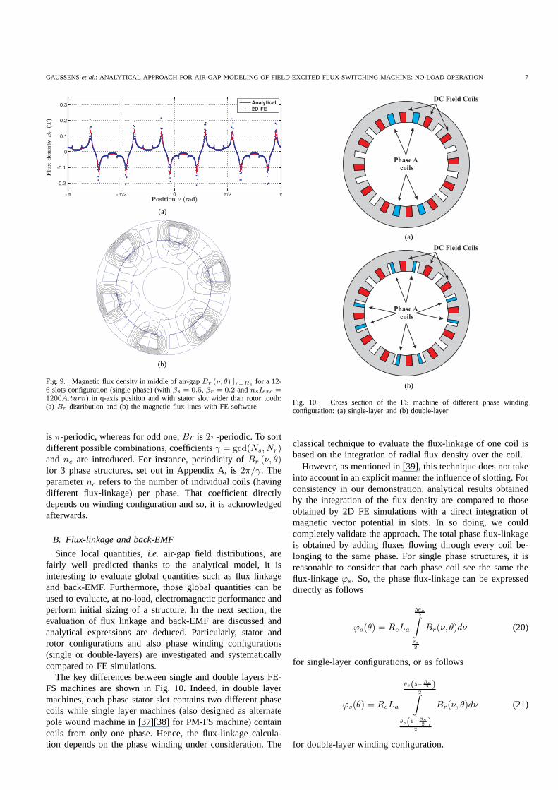
and FE results. The relative error for the peak flux densitydoes not exceed3%. Furthermore, the flux-switching principlecan be observed by carefully examining Figs. 8.(a) and (c),i.e., for maximum and minimum flux-linkage in the phase.Indeed, the air-gap flux density is locally inverted (or switched)over the coil phase leading to a bipolar flux-linkage. Even forconfigurations which are difficult to model, such as in thatshown in Fig. 9, where the stator slot opening is wider thanthe rotor tooth width, the analytical model gives quite a goodevaluation of the air-gap field.
While for single phase structures, the no-load field distribu-tion in the air-gap is well accounted for with4π
Nrperiodicity.
We explore in the next sectionq-phase structures.
2) Multi-phase structures
Air-gap field distribution for multi-phase structures is morecomplicated to assess, with symmetry often over180 or 360
(for non-symmetrical configurations). Indeed, unlike single-phase structures, we cannot define clearly a stator-rotor com-bination (Ns −Nr). For one stator configuration, many rotorcombinations are likely to work. While the model is devotedto multi-phase topologies, a special emphasis will be placedon 3 phase (q = 3) structures. In the interest of clarity andsimplification, radial air-gap field distributions atr = Re for a24 stator slots configuration (3 phases) and different rotorteethare proposed in Appendix A (Figs. 19, 20, 21 and 22). It can beseen that with an even number of rotor teeth,Br distribution
GAUSSENSet al.: ANALYTICAL APPROACH FOR AIR-GAP MODELING OF FIELD-EXCITED FLUX-SWITCHING MACHINE: NO-LOAD OPERATION 7
(a)
(b)
Fig. 9. Magnetic flux density in middle of air-gapBr (ν, θ) |r=Refor a 12-
6 slots configuration (single phase) (withβs = 0.5, βr = 0.2 andnsIexc =1200A.turn) in q-axis position and with stator slot wider than rotor tooth:(a) Br distribution and (b) the magnetic flux lines with FE software
is π-periodic, whereas for odd one,Br is 2π-periodic. To sortdifferent possible combinations, coefficientsγ = gcd(Ns, Nr)and nc are introduced. For instance, periodicity ofBr (ν, θ)for 3 phase structures, set out in Appendix A, is2π/γ. Theparameternc refers to the number of individual coils (havingdifferent flux-linkage) per phase. That coefficient directlydepends on winding configuration and so, it is acknowledgedafterwards.
B. Flux-linkage and back-EMF
Since local quantities,i.e. air-gap field distributions, arefairly well predicted thanks to the analytical model, it isinteresting to evaluate global quantities such as flux linkageand back-EMF. Furthermore, those global quantities can beused to evaluate, at no-load, electromagnetic performanceandperform initial sizing of a structure. In the next section, theevaluation of flux linkage and back-EMF are discussed andanalytical expressions are deduced. Particularly, statorandrotor configurations and also phase winding configurations(single or double-layers) are investigated and systematicallycompared to FE simulations.
The key differences between single and double layers FE-FS machines are shown in Fig. 10. Indeed, in double layermachines, each phase stator slot contains two different phasecoils while single layer machines (also designed as alternatepole wound machine in [37][38] for PM-FS machine) containcoils from only one phase. Hence, the flux-linkage calcula-tion depends on the phase winding under consideration. The
DC Field Coils
Phase A
coils
(a)
DC Field Coils
Phase A
coils
(b)
Fig. 10. Cross section of the FS machine of different phase windingconfiguration: (a) single-layer and (b) double-layer
classical technique to evaluate the flux-linkage of one coilisbased on the integration of radial flux density over the coil.
However, as mentioned in [39], this technique does not takeinto account in an explicit manner the influence of slotting.Forconsistency in our demonstration, analytical results obtainedby the integration of the flux density are compared to thoseobtained by 2D FE simulations with a direct integration ofmagnetic vector potential in slots. In so doing, we couldcompletely validate the approach. The total phase flux-linkageis obtained by adding fluxes flowing through every coil be-longing to the same phase. For single phase structures, it isreasonable to consider that each phase coil see the same theflux-linkageϕs. So, the phase flux-linkage can be expresseddirectly as follows
ϕs(θ) = ReLa
5θs2
∫
θs2
Br(ν, θ)dν (20)
for single-layer configurations, or as follows
ϕs(θ) = ReLa
θs(5− βs2 )
2∫
θs(1+ βs2 )
2
Br(ν, θ)dν (21)
for double-layer winding configuration.
8 IEEE TRANSACTIONS ON MAGNETICS, VOL. X, NO. X, X 2012
In multi-phase structures, as we shall see in subsequentsections, flux-linkages of different coils of the same phasediffer. This phenomenon, firstly reported in [22], is inherentto FS machines, since relative positions between stator androtor tooth over each coil are different. Hereafter, expressionsof global flux-linkage depending on winding configurationand number of rotor teethNr are derived. For the sake ofclarity, only configurations withNr = Ns/2 ± γ have beeninvestigated. Nevertheless, those configurations are the mostpromising in terms of power capability.
Finally, once the total flux-linkage is obtained, the back-EMF Es is determined from
Es = −NtspΩπ
30
dϕs
dθ(22)
with Ntsp the number of turns in series per phase.Analytical evaluation of flux-linkage and back-EMF are,
hereafter, compared to 2D FE simulations.1) Single-layer configurationThe overall flux-linkage for single-layer winding configura-
tions havingγ ≥ 2 andnc = Ns/4qγ coils can be derived as(20). Indeed, like single phase structures, the relative positionbetween each phase coil and the rotor tooth is the same.
With regard to configurations withγ = 1 andnc = Ns/4qcoils, the total flux-linkage is found to be, fornc = 2,
ϕs (θ) =ReLa
nc
nc−1∑
i=0
(−1)i
θs(5+8qi)2
∫
θs(1+8qi)2
Br(ν, θ)dν
(23)
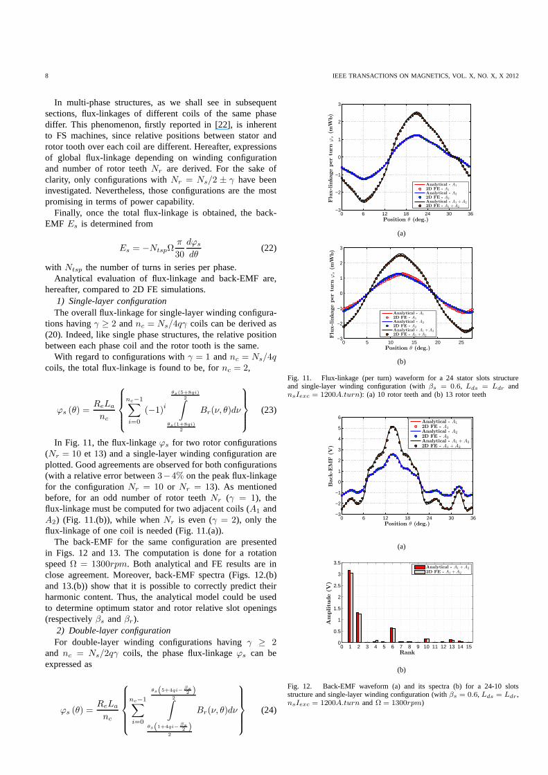
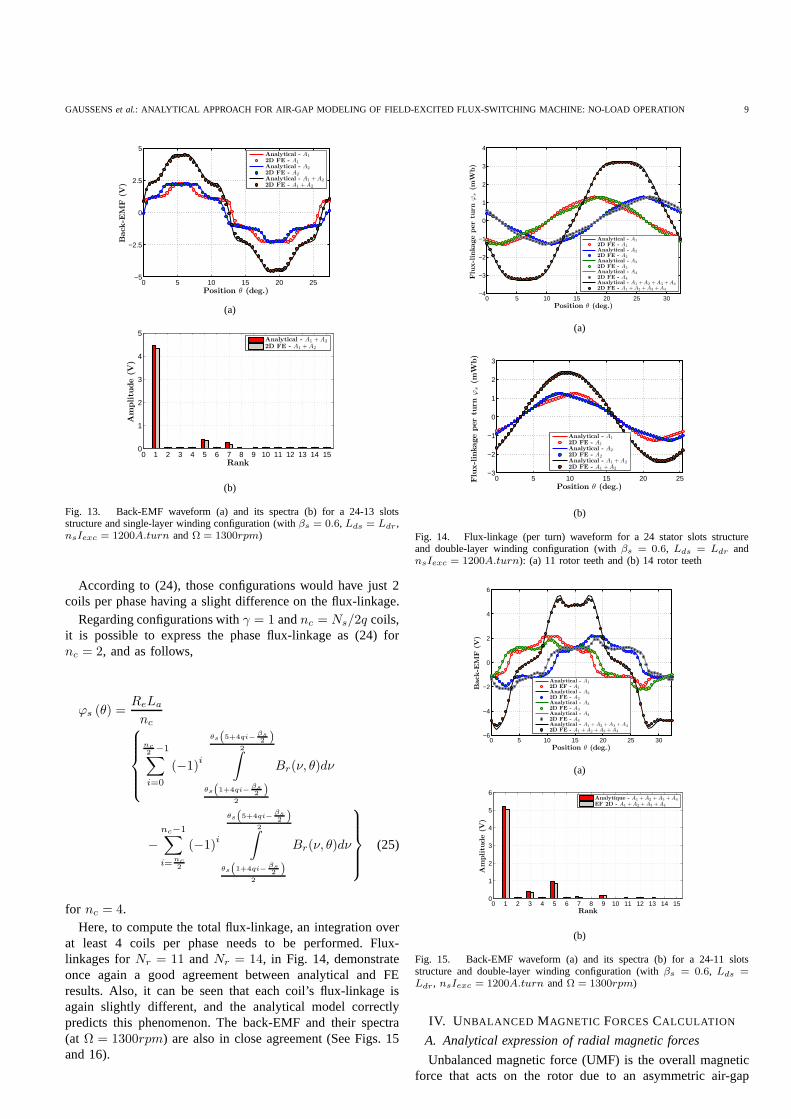
In Fig. 11, the flux-linkageϕs for two rotor configurations(Nr = 10 et 13) and a single-layer winding configuration areplotted. Good agreements are observed for both configurations(with a relative error between3−4% on the peak flux-linkagefor the configurationNr = 10 or Nr = 13). As mentionedbefore, for an odd number of rotor teethNr (γ = 1), theflux-linkage must be computed for two adjacent coils (A1 andA2) (Fig. 11.(b)), while whenNr is even (γ = 2), only theflux-linkage of one coil is needed (Fig. 11.(a)).
The back-EMF for the same configuration are presentedin Figs. 12 and 13. The computation is done for a rotationspeedΩ = 1300rpm. Both analytical and FE results are inclose agreement. Moreover, back-EMF spectra (Figs. 12.(b)and 13.(b)) show that it is possible to correctly predict theirharmonic content. Thus, the analytical model could be usedto determine optimum stator and rotor relative slot openings(respectivelyβs andβr).
2) Double-layer configurationFor double-layer winding configurations havingγ ≥ 2
and nc = Ns/2qγ coils, the phase flux-linkageϕs can beexpressed as
ϕs (θ) =ReLa
nc
nc−1∑
i=0
θs(5+4qi−βs2 )
2∫
θs(1+4qi−βs2 )
2
Br(ν, θ)dν
(24)
0 6 12 18 24 30 36−3
−2
−1
0
1
2
3
Position θ (deg.)
Flu
x-lin
kage
per
turn
ϕs
(mW
b)
Analytical - A1
2D FE - A1
Analytical - A2
2D FE - A2
Analytical - A1 + A2
2D FE - A1 + A2
(a)
0 5 10 15 20 25−3
−2
−1
0
1
2
3
Position θ (deg.)
Flu
x-lin
kage
per
turn
ϕs
(mW
b)
Analytical - A1
2D FE - A1
Analytical - A2
2D FE - A2
Analytical - A1 + A2
2D FE - A1 + A2
(b)
Fig. 11. Flux-linkage (per turn) waveform for a 24 stator slots structureand single-layer winding configuration (withβs = 0.6, Lds = Ldr andnsIexc = 1200A.turn): (a) 10 rotor teeth and (b) 13 rotor teeth
0 6 12 18 24 30 36−3
−2
−1
0
1
2
3
4
5
6
Position θ (deg.)
Back
-EM
F(V
)
Analytical - A1
2D FE - A1
Analytical - A2
2D FE - A2
Analytical - A1 + A2
2D FE - A1 + A2
(a)
0 1 2 3 4 5 6 7 8 9 10 11 12 13 14 150
0.5
1
1.5
2
2.5
3
3.5
Rank
Am
plitu
de
(V)
Analytical - A1 + A2
2D FE - A1 + A2
(b)
Fig. 12. Back-EMF waveform (a) and its spectra (b) for a 24-10slotsstructure and single-layer winding configuration (withβs = 0.6, Lds = Ldr,nsIexc = 1200A.turn andΩ = 1300rpm)
GAUSSENSet al.: ANALYTICAL APPROACH FOR AIR-GAP MODELING OF FIELD-EXCITED FLUX-SWITCHING MACHINE: NO-LOAD OPERATION 9
0 5 10 15 20 25−5
−2.5
0
2.5
5
Position θ (deg.)
Back
-EM
F(V
)
Analytical - A1
2D FE - A1
Analytical - A2
2D FE - A2
Analytical - A1 + A2
2D FE - A1 + A2
(a)
0 1 2 3 4 5 6 7 8 9 10 11 12 13 14 150
1
2
3
4
5
Rank
Am
plitu
de
(V)
Analytical - A1 + A2
2D FE - A1 + A2
(b)
Fig. 13. Back-EMF waveform (a) and its spectra (b) for a 24-13slotsstructure and single-layer winding configuration (withβs = 0.6, Lds = Ldr ,nsIexc = 1200A.turn andΩ = 1300rpm)
According to (24), those configurations would have just 2coils per phase having a slight difference on the flux-linkage.
Regarding configurations withγ = 1 andnc = Ns/2q coils,it is possible to express the phase flux-linkage as (24) fornc = 2, and as follows,
ϕs (θ) =ReLa
nc
nc2 −1∑
i=0
(−1)i
θs(5+4qi−βs2 )
2∫
θs(1+4qi−βs2 )
2
Br(ν, θ)dν
−
nc−1∑
i=nc2
(−1)i
θs(5+4qi−βs2 )
2∫
θs(1+4qi−βs2 )
2
Br(ν, θ)dν
(25)
for nc = 4.Here, to compute the total flux-linkage, an integration over
at least 4 coils per phase needs to be performed. Flux-linkages forNr = 11 andNr = 14, in Fig. 14, demonstrateonce again a good agreement between analytical and FEresults. Also, it can be seen that each coil’s flux-linkage isagain slightly different, and the analytical model correctlypredicts this phenomenon. The back-EMF and their spectra(at Ω = 1300rpm) are also in close agreement (See Figs. 15and 16).
0 5 10 15 20 25 30−4
−3
−2
−1
0
1
2
3
4
Position θ (deg.)
Flu
x-lin
kage
per
turn
ϕs
(mW
b)
Analytical - A1
2D FE - A1
Analytical - A2
2D FE - A2
Analytical - A3
2D FE - A3
Analytical - A4
2D FE - A4
Analytical - A1 + A2 + A3 + A4
2D FE - A1 + A2 + A3 + A4
(a)
0 5 10 15 20 25−3
−2
−1
0
1
2
3
Position θ (deg.)
Flu
x-lin
kage
per
turn
ϕs
(mW
b)
Analytical - A1
2D FE - A1
Analytical - A2
2D FE - A2
Analytical - A1 + A2
2D FE - A1 + A2
(b)
Fig. 14. Flux-linkage (per turn) waveform for a 24 stator slots structureand double-layer winding configuration (withβs = 0.6, Lds = Ldr andnsIexc = 1200A.turn): (a) 11 rotor teeth and (b) 14 rotor teeth
0 5 10 15 20 25 30−6
−4
−2
0
2
4
6
Position θ (deg.)
Back
-EM
F(V
)
Analytical - A1
2D EF - A1
Analytical - A2
2D FE - A2
Analytical - A3
2D FE - A3
Analytical - A4
2D FE - A4
Analytical - A1 + A2 + A3 + A4
2D FE - A1 + A2 + A3 + A4
(a)
0 1 2 3 4 5 6 7 8 9 10 11 12 13 14 150
1
2
3
4
5
6
Rank
Am
plitu
de
(V)
Analytique - A1 + A2 + A3 + A4
EF 2D - A1 + A2 + A3 + A4
(b)
Fig. 15. Back-EMF waveform (a) and its spectra (b) for a 24-11slotsstructure and double-layer winding configuration (withβs = 0.6, Lds =Ldr, nsIexc = 1200A.turn andΩ = 1300rpm)
IV. U NBALANCED MAGNETIC FORCESCALCULATION
A. Analytical expression of radial magnetic forces
Unbalanced magnetic force (UMF) is the overall magneticforce that acts on the rotor due to an asymmetric air-gap
10 IEEE TRANSACTIONS ON MAGNETICS, VOL. X, NO. X, X 2012
(a) (b) (c) (d)
Fig. 17. Magnetic pressurePm (ν, θ) |r=Refor a 24 stator slots structure (withβs = 0.6, Lds = Ldr andnsIexc = 1200A.turn): (a) 10 rotor teeth,
(b) 11 rotor teeth, (c) 13 rotor teeth and (d) 14 rotor teeth
0 5 10 15 20 25−5
−3
−1
1
3
5
Position θ (deg.)
Back
-EM
F(V
)
Analytical - A1
2D FE - A1
Analytical - A2
2D FE - A2
Analytical - A1 + A2
2D FE - A1 + A2
(a)
0 1 2 3 4 5 6 7 8 9 10 11 12 13 14 150
1
2
3
4
5
Rank
Am
plitu
de
(V)
Analytique - A1 + A2
EF 2D - A1 + A2
(b)
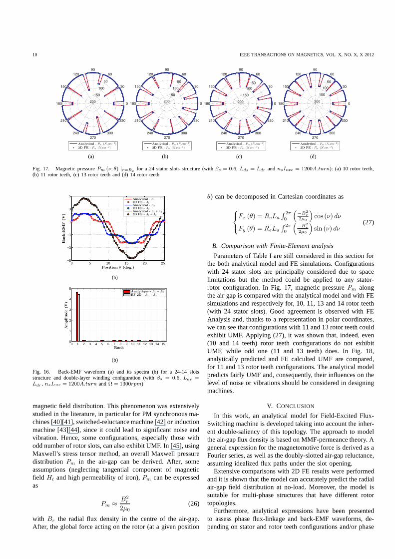
Fig. 16. Back-EMF waveform (a) and its spectra (b) for a 24-14slotsstructure and double-layer winding configuration (withβs = 0.6, Lds =Ldr , nsIexc = 1200A.turn andΩ = 1300rpm)
magnetic field distribution. This phenomenon was extensivelystudied in the literature, in particular for PM synchronousma-chines [40][41], switched-reluctance machine [42] or inductionmachine [43][44], since it could lead to significant noise andvibration. Hence, some configurations, especially those withodd number of rotor slots, can also exhibit UMF. In [45], usingMaxwell’s stress tensor method, an overall Maxwell pressuredistribution Pm in the air-gap can be derived. After, someassumptions (neglecting tangential component of magneticfield Ht and high permeability of iron),Pm can be expressedas
Pm ≈B2
r
2µ0(26)
with Br the radial flux density in the centre of the air-gap.After, the global force acting on the rotor (at a given position
θ) can be decomposed in Cartesian coordinates as
Fx (θ) = ReLa
∫ 2π
0
(
−B2r
2µ0
)
cos (ν) dν
Fy (θ) = ReLa
∫ 2π
0
(
−B2r
2µ0
)
sin (ν) dν(27)
B. Comparison with Finite-Element analysis
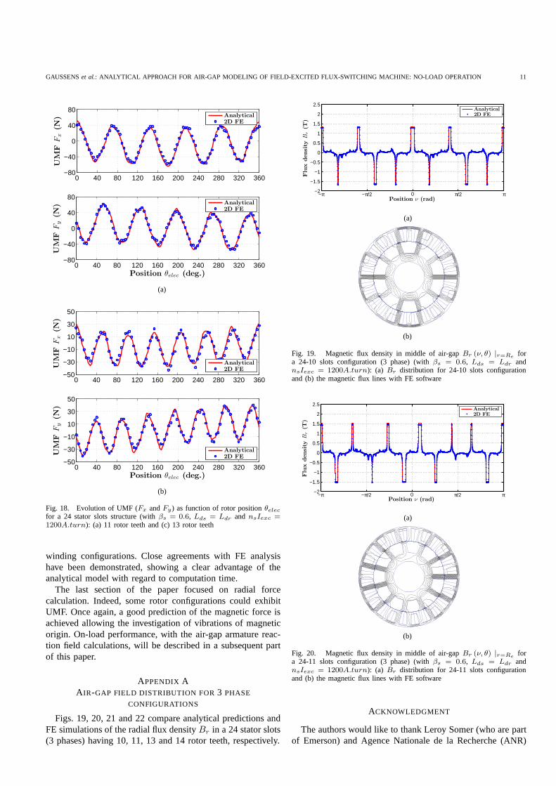
Parameters of Table I are still considered in this section forthe both analytical model and FE simulations. Configurationswith 24 stator slots are principally considered due to spacelimitations but the method could be applied to any stator-rotor configuration. In Fig. 17, magnetic pressurePm alongthe air-gap is compared with the analytical model and with FEsimulations and respectively for, 10, 11, 13 and 14 rotor teeth(with 24 stator slots). Good agreement is observed with FEAnalysis and, thanks to a representation in polar coordinates,we can see that configurations with 11 and 13 rotor teeth couldexhibit UMF. Applying (27), it was shown that, indeed, even(10 and 14 teeth) rotor teeth configurations do not exhibitUMF, while odd one (11 and 13 teeth) does. In Fig. 18,analytically predicted and FE calculted UMF are compared,for 11 and 13 rotor teeth configurations. The analytical modelpredicts fairly UMF and, consequently, their influences on thelevel of noise or vibrations should be considered in designingmachines.
V. CONCLUSION
In this work, an analytical model for Field-Excited Flux-Switching machine is developed taking into account the inher-ent double-saliency of this topology. The approach to modelthe air-gap flux density is based on MMF-permeance theory. Ageneral expression for the magnetomotive force is derived as aFourier series, as well as the doubly-slotted air-gap reluctance,assuming idealized flux paths under the slot opening.
Extensive comparisons with 2D FE results were performedand it is shown that the model can accurately predict the radialair-gap field distribution at no-load. Moreover, the model issuitable for multi-phase structures that have different rotortopologies.
Furthermore, analytical expressions have been presentedto assess phase flux-linkage and back-EMF waveforms, de-pending on stator and rotor teeth configurations and/or phase
GAUSSENSet al.: ANALYTICAL APPROACH FOR AIR-GAP MODELING OF FIELD-EXCITED FLUX-SWITCHING MACHINE: NO-LOAD OPERATION 11
0 40 80 120 160 200 240 280 320 360−80
−40
0
40
80
UM
FF
x(N
)
Analytical2D FE
0 40 80 120 160 200 240 280 320 360−80
−40
0
40
80
Position θelec (deg.)
UM
FF
y(N
)
Analytical2D FE
(a)
0 40 80 120 160 200 240 280 320 360−50
−30
−10
10
30
50
UM
FF
x(N
)
Analytical2D FE
0 40 80 120 160 200 240 280 320 360−50
−30
−10
10
30
50
Position θelec (deg.)
UM
FF
y(N
)
Analytical2D FE
(b)
Fig. 18. Evolution of UMF (Fx andFy) as function of rotor positionθelecfor a 24 stator slots structure (withβs = 0.6, Lds = Ldr and nsIexc =1200A.turn): (a) 11 rotor teeth and (c) 13 rotor teeth
winding configurations. Close agreements with FE analysishave been demonstrated, showing a clear advantage of theanalytical model with regard to computation time.
The last section of the paper focused on radial forcecalculation. Indeed, some rotor configurations could exhibitUMF. Once again, a good prediction of the magnetic force isachieved allowing the investigation of vibrations of magneticorigin. On-load performance, with the air-gap armature reac-tion field calculations, will be described in a subsequent partof this paper.
APPENDIX AA IR-GAP FIELD DISTRIBUTION FOR3 PHASE
CONFIGURATIONS
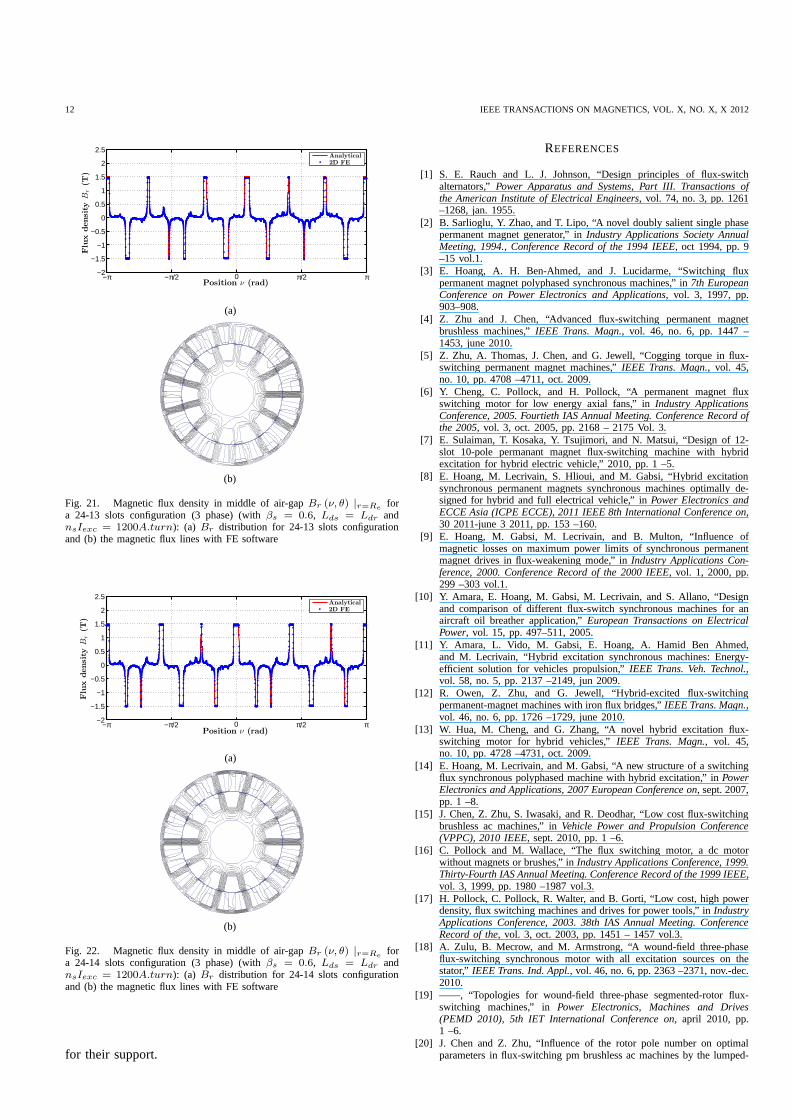
Figs. 19, 20, 21 and 22 compare analytical predictions andFE simulations of the radial flux densityBr in a 24 stator slots(3 phases) having 10, 11, 13 and 14 rotor teeth, respectively.
−2
−1.5
−1
−0.5
0
0.5
1
1.5
2
2.5
Position ν (rad)
Flu
xdensi
tyB
r(T
)
−π −π/2 0 π/2 π
Analytical2D FE
(a)
(b)
Fig. 19. Magnetic flux density in middle of air-gapBr (ν, θ) |r=Refor
a 24-10 slots configuration (3 phase) (withβs = 0.6, Lds = Ldr andnsIexc = 1200A.turn): (a) Br distribution for 24-10 slots configurationand (b) the magnetic flux lines with FE software
−2
−1.5
−1
−0.5
0
0.5
1
1.5
2
2.5
Position ν (rad)
Flu
xdensi
tyB
r(T
)
−π −π/2 0 π/2 π
Analytical2D FE
(a)
(b)
Fig. 20. Magnetic flux density in middle of air-gapBr (ν, θ) |r=Refor
a 24-11 slots configuration (3 phase) (withβs = 0.6, Lds = Ldr andnsIexc = 1200A.turn): (a) Br distribution for 24-11 slots configurationand (b) the magnetic flux lines with FE software
ACKNOWLEDGMENT
The authors would like to thank Leroy Somer (who are partof Emerson) and Agence Nationale de la Recherche (ANR)
12 IEEE TRANSACTIONS ON MAGNETICS, VOL. X, NO. X, X 2012
−2
−1.5
−1
−0.5
0
0.5
1
1.5
2
2.5
Position ν (rad)
Flu
xdensi
tyB
r(T
)
−π −π/2 0 π/2 π
Analytical2D FE
(a)
(b)
Fig. 21. Magnetic flux density in middle of air-gapBr (ν, θ) |r=Refor
a 24-13 slots configuration (3 phase) (withβs = 0.6, Lds = Ldr andnsIexc = 1200A.turn): (a) Br distribution for 24-13 slots configurationand (b) the magnetic flux lines with FE software
−2
−1.5
−1
−0.5
0
0.5
1
1.5
2
2.5
Position ν (rad)
Flu
xdensi
tyB
r(T
)
−π −π/2 0 π/2 π
Analytical2D FE
(a)
(b)
Fig. 22. Magnetic flux density in middle of air-gapBr (ν, θ) |r=Refor
a 24-14 slots configuration (3 phase) (withβs = 0.6, Lds = Ldr andnsIexc = 1200A.turn): (a) Br distribution for 24-14 slots configurationand (b) the magnetic flux lines with FE software
for their support.
REFERENCES
[1] S. E. Rauch and L. J. Johnson, “Design principles of flux-switchalternators,”Power Apparatus and Systems, Part III. Transactions ofthe American Institute of Electrical Engineers, vol. 74, no. 3, pp. 1261–1268, jan. 1955.
[2] B. Sarlioglu, Y. Zhao, and T. Lipo, “A novel doubly salient single phasepermanent magnet generator,” inIndustry Applications Society AnnualMeeting, 1994., Conference Record of the 1994 IEEE, oct 1994, pp. 9–15 vol.1.
[3] E. Hoang, A. H. Ben-Ahmed, and J. Lucidarme, “Switching fluxpermanent magnet polyphased synchronous machines,” in7th EuropeanConference on Power Electronics and Applications, vol. 3, 1997, pp.903–908.
[4] Z. Zhu and J. Chen, “Advanced flux-switching permanent magnetbrushless machines,”IEEE Trans. Magn., vol. 46, no. 6, pp. 1447 –1453, june 2010.
[5] Z. Zhu, A. Thomas, J. Chen, and G. Jewell, “Cogging torquein flux-switching permanent magnet machines,”IEEE Trans. Magn., vol. 45,no. 10, pp. 4708 –4711, oct. 2009.
[6] Y. Cheng, C. Pollock, and H. Pollock, “A permanent magnetfluxswitching motor for low energy axial fans,” inIndustry ApplicationsConference, 2005. Fourtieth IAS Annual Meeting. Conference Record ofthe 2005, vol. 3, oct. 2005, pp. 2168 – 2175 Vol. 3.
[7] E. Sulaiman, T. Kosaka, Y. Tsujimori, and N. Matsui, “Design of 12-slot 10-pole permanant magnet flux-switching machine with hybridexcitation for hybrid electric vehicle,” 2010, pp. 1 –5.
[8] E. Hoang, M. Lecrivain, S. Hlioui, and M. Gabsi, “Hybrid excitationsynchronous permanent magnets synchronous machines optimally de-signed for hybrid and full electrical vehicle,” inPower Electronics andECCE Asia (ICPE ECCE), 2011 IEEE 8th International Conference on,30 2011-june 3 2011, pp. 153 –160.
[9] E. Hoang, M. Gabsi, M. Lecrivain, and B. Multon, “Influence ofmagnetic losses on maximum power limits of synchronous permanentmagnet drives in flux-weakening mode,” inIndustry Applications Con-ference, 2000. Conference Record of the 2000 IEEE, vol. 1, 2000, pp.299 –303 vol.1.
[10] Y. Amara, E. Hoang, M. Gabsi, M. Lecrivain, and S. Allano, “Designand comparison of different flux-switch synchronous machines for anaircraft oil breather application,”European Transactions on ElectricalPower, vol. 15, pp. 497–511, 2005.
[11] Y. Amara, L. Vido, M. Gabsi, E. Hoang, A. Hamid Ben Ahmed,and M. Lecrivain, “Hybrid excitation synchronous machines: Energy-efficient solution for vehicles propulsion,”IEEE Trans. Veh. Technol.,vol. 58, no. 5, pp. 2137 –2149, jun 2009.
[12] R. Owen, Z. Zhu, and G. Jewell, “Hybrid-excited flux-switchingpermanent-magnet machines with iron flux bridges,”IEEE Trans. Magn.,vol. 46, no. 6, pp. 1726 –1729, june 2010.
[13] W. Hua, M. Cheng, and G. Zhang, “A novel hybrid excitation flux-switching motor for hybrid vehicles,”IEEE Trans. Magn., vol. 45,no. 10, pp. 4728 –4731, oct. 2009.
[14] E. Hoang, M. Lecrivain, and M. Gabsi, “A new structure ofa switchingflux synchronous polyphased machine with hybrid excitation,” in PowerElectronics and Applications, 2007 European Conference on, sept. 2007,pp. 1 –8.
[15] J. Chen, Z. Zhu, S. Iwasaki, and R. Deodhar, “Low cost flux-switchingbrushless ac machines,” inVehicle Power and Propulsion Conference(VPPC), 2010 IEEE, sept. 2010, pp. 1 –6.
[16] C. Pollock and M. Wallace, “The flux switching motor, a dcmotorwithout magnets or brushes,” inIndustry Applications Conference, 1999.Thirty-Fourth IAS Annual Meeting. Conference Record of the1999 IEEE,vol. 3, 1999, pp. 1980 –1987 vol.3.
[17] H. Pollock, C. Pollock, R. Walter, and B. Gorti, “Low cost, high powerdensity, flux switching machines and drives for power tools,” in IndustryApplications Conference, 2003. 38th IAS Annual Meeting. ConferenceRecord of the, vol. 3, oct. 2003, pp. 1451 – 1457 vol.3.
[18] A. Zulu, B. Mecrow, and M. Armstrong, “A wound-field three-phaseflux-switching synchronous motor with all excitation sources on thestator,” IEEE Trans. Ind. Appl., vol. 46, no. 6, pp. 2363 –2371, nov.-dec.2010.
[19] ——, “Topologies for wound-field three-phase segmented-rotor flux-switching machines,” inPower Electronics, Machines and Drives(PEMD 2010), 5th IET International Conference on, april 2010, pp.1 –6.
[20] J. Chen and Z. Zhu, “Influence of the rotor pole number on optimalparameters in flux-switching pm brushless ac machines by thelumped-
GAUSSENSet al.: ANALYTICAL APPROACH FOR AIR-GAP MODELING OF FIELD-EXCITED FLUX-SWITCHING MACHINE: NO-LOAD OPERATION 13
parameter magnetic circuit model,”IEEE Trans. Ind. Appl., vol. 46,no. 4, pp. 1381 –1388, july-aug. 2010.
[21] Y. Pang, Z. Zhu, D. Howe, S. Iwasaki, R. Deodhar, and A. Pride,“Eddy current loss in the frame of a flux-switching permanentmagnetmachine,” IEEE Trans. Magn., vol. 42, no. 10, pp. 3413 –3415, oct.2006.
[22] Z. Zhu, Y. Pang, D. Howe, S. Iwasaki, R. Deodhar, and A. Pride,“Analysis of electromagnetic performance of flux-switching permanent-magnet machines by nonlinear adaptive lumped parameter magneticcircuit model,” IEEE Trans. Magn., vol. 41, no. 11, pp. 4277 – 4287,nov. 2005.
[23] B. Gysen, E. Ilhan, K. Meessen, J. Paulides, and E. Lomonova, “Model-ing of flux switching permanent magnet machines with fourieranalysis,”IEEE Trans. Magn., vol. 46, no. 6, pp. 1499 –1502, june 2010.
[24] E. Ilhan, B. Gysen, J. Paulides, and E. Lomonova, “Analytical hybridmodel for flux switching permanent magnet machines,”IEEE Trans.Magn., vol. 46, no. 6, pp. 1762 –1765, june 2010.
[25] W. J. Gibbs,Conformal transformations in electrical engineering. Lon-don: Chapman & Hall, 1958.
[26] V. Hamata and B. Heller,Harmonic field effects in induction machines.Elsevier Scientific Pub. Co., 1977.
[27] Z. Zhu and D. Howe, “Instantaneous magnetic field distribution inbrushless permanent magnet dc motors. iii. effect of statorslotting,”IEEE Trans. Magn., vol. 29, no. 1, pp. 143 –151, jan 1993.
[28] D. Zarko, D. Ban, and T. Lipo, “Analytical calculation of magnetic fielddistribution in the slotted air gap of a surface permanent-magnet motorusing complex relative air-gap permeance,”IEEE Trans. Magn., vol. 42,no. 7, pp. 1828 – 1837, july 2006.
[29] ——, “Analytical solution for cogging torque in surfacepermanent-magnet motors using conformal mapping,”IEEE Trans. Magn., vol. 44,no. 1, pp. 52 –65, jan. 2008.
[30] T. Lubin, T. Hamiti, H. Razik, and A. Rezzoug, “Comparison betweenfinite-element analysis and winding function theory for inductances andtorque calculation of a synchronous reluctance machine,”IEEE Trans.Magn., vol. 43, no. 8, pp. 3406 –3410, aug. 2007.
[31] U. Kim and D. Lieu, “Magnetic field calculation in permanent magnetmotors with rotor eccentricity: with slotting effect considered,” IEEETrans. Magn., vol. 34, no. 4, pp. 2253 –2266, jul 1998.
[32] G. Dajaku and D. Gerling, “Stator slotting effect on themagnetic fielddistribution of salient pole synchronous permanent-magnet machines,”IEEE Trans. Magn., vol. 46, no. 9, pp. 3676 –3683, sept. 2010.
[33] Z. Zhu, L. Wu, and Z. Xia, “An accurate subdomain model for mag-netic field computation in slotted surface-mounted permanent-magnetmachines,”IEEE Trans. Magn., vol. 46, no. 4, pp. 1100 –1115, april2010.
[34] T. Lubin, S. Mezani, and A. Rezzoug, “Exact analytical method formagnetic field computation in the air gap of cylindrical electricalmachines considering slotting effects,”IEEE Trans. Magn., vol. 46,no. 4, pp. 1092 –1099, april 2010.
[35] Z. Liu and J. Li, “Analytical solution of air-gap field inpermanent-magnet motors taking into account the effect of pole transition overslots,” IEEE Trans. Magn., vol. 43, no. 10, pp. 3872 –3883, oct. 2007.
[36] F. Dubas and C. Espanet, “Analytical solution of the magnetic fieldin permanent-magnet motors taking into account slotting effect: No-load vector potential and flux density calculation,”IEEE Trans. Magn.,vol. 45, no. 5, pp. 2097 –2109, may 2009.
[37] R. Owen, Z. Zhu, A. Thomas, G. Jewell, and D. Howe, “Alternate poleswound flux-switching permanent-magnet brushless ac machines,” IEEETrans. Ind. Appl., vol. 46, no. 2, pp. 790 –797, march-april 2010.
[38] J. Chen and Z. Zhu, “Winding configurations and optimal stator androtor pole combination of flux-switching pm brushless ac machines,”IEEE Trans. Energy Convers., vol. 25, no. 2, pp. 293 –302, june 2010.
[39] H. Tiegna, A. Bellara, Y. Amara, and G. Barakat, “Analytical modelingof the open-circuit magnetic field in axial flux permanent magnetmachines with semi-closed slots,”IEEE Trans. Magn., vol. PP, no. 99,p. 1, 2011.
[40] Z. Zhu, Z. Xia, L. Wu, and G. Jewell, “Analytical modeling andfinite-element computation of radial vibration force in fractional-slotpermanent-magnet brushless machines,”IEEE Trans. Ind. Appl., vol. 46,no. 5, pp. 1908 –1918, sept.-oct. 2010.
[41] Z. Liu and J. Li, “Accurate prediction of magnetic field and magneticforces in permanent magnet motors using an analytical solution,” IEEETrans. Energy Convers., vol. 23, no. 3, pp. 717 –726, sept. 2008.
[42] M. Anwar and O. Husain, “Radial force calculation and acoustic noiseprediction in switched reluctance machines,”IEEE Trans. Ind. Appl.,vol. 36, no. 6, pp. 1589 – 1597, nov/dec 2000.
[43] S. Verma and A. Balan, “Determination of radial-forcesin relation tonoise and vibration problems of squirrel-cage induction motors,” IEEETrans. Energy Convers., vol. 9, no. 2, pp. 404 –412, jun 1994.
[44] D. Im, J. Chang, S. Park, B. Kwon, J. Hong, and B. Kim, “Analysis ofradial force as a source of vibration in an induction motor with skewedslots,” IEEE Trans. Magn., vol. 33, no. 2, pp. 1650 –1653, mar 1997.
[45] J. Le Besnerais, V. Lanfranchi, M. Hecquet, and P. Brochet, “Optimalslot numbers for magnetic noise reduction in variable-speed inductionmotors,” IEEE Trans. Magn., vol. 45, no. 8, pp. 3131 –3136, aug. 2009.
Gaussens Benjaminwas born in Toulouse, France, in 1987. He received theM.Sc. degree in electrical engineering from the Institut National Polytechnique(ENSEEIHT), Toulouse, France. He is currently working toward the Ph.D.degree still in electrical engineering at SATIE, ENS Cachan, CNRS, Univer-Sud. His current research interests include design of innovative topology ofelectromagnetic actuators and their modeling.
Hoang Emmanuel was born in Antibes, France, in 1966. He received the”agregation” in electrical engineering in 1990 and the Ph.D. degree from theEcole Normale Superieure de Cachan in 1995. Since 1990, he has worked withthe electrical machine team in the SATIE laboratory. His research interestsinclude the modeling of the iron losses in SRMs and the design, modeling,optimization, and control of novel topologies of PM machines.
De la Barri ere Olivier was born in Paris, France, in 1982. He receivedthe M.Sc. degree in electronics from the Ecole Nationale Superieure del’Electronique et de ses Applications (ENSEA), and the Ph.D. degree inelectrical engineering from the Ecole Normale Suprieure deCachan. He isnow a Reseacher at SATIE, ENS Cachan, CNRS, UniverSud. His researchtopics include analytical modelling of electrical actuators, and also the studyof new magnetic materials for electrical engineering applications.
Saint-Michel Jacques was born in 1949. He received the degree in engi-neering from Ecole Centrale de Paris, Paris, France, in 1972, and the Ph.D.degree from the University of Paris VI, Paris. From 1972 to 1982, he waswith the French National Scientific Research Center (CNRS).In 1982, hejoined Jeumont Schneider as the Head of the Design and Planning Departmentand remained with them until 1990. In 1990, he joined Leroy-Somer Motor,Angouleme, France, as a Technical Manager, becoming Scientific Director in1998.
Lecrivain Michel was born in Barneville, France. He received the degreein electrical engineering from the Conservatoire Nationaldes Arts et Metiers(CNAM, Paris, France) in 1981. In 1997 he joined SATIE laboratory as aResearch Engineer. His research interests include the design and control ofnew hybrid machines and novel permanent-magnet machines for automotiveapplications.
Gabsi Mohamed received the Ph.D. degree in electrical engineering fromUniversity of Paris-VI in 1987 and the HDR in 1999 from Universityof Paris-XI (Orsay, France). Since 1990, he has been workingwith theelectrical machine team (SETE, Systemes d’Energies pour le Transport etl’Environnement) of SATIE laboratory where he is currentlya Full Professorand the Director of the Electrical Engineering Department.His researchinterests include SRM, vibrations and acoustic noise, and PM machines.
Related Documents