22nd International Congress of Mechanical Engineering (COBEM 2013) November 3-7, 2013, Ribeirão Preto, SP, Brazil Copyright © 2013 by ABCM ANALYSIS TOOL AND COMPUTER SIMULATION OF A DOUBLE LOBED HYPERBOLIC OMNIDIRECTIONAL CATADIOPTRIC VISION SYSTEM Marcello Marinho Ribeiro, [email protected] José Maurício S. T. da Motta, [email protected] Departamento de Engenharia Mecânica, Faculdade de Tecnologia, Universidade de Brasília, Campus Universitário Darcy Ribeiro, Asa Norte, 70910-900, Brasília, Brasil. Abstract. An omnidirectional catadioptric vision system has the capacity to acquire images with a 360° field-of-view by using a convex mirror. A hyperbolic double lobed mirror has the single view point property, which allows the acquisition of two different images of the same scene simultaneously, making possible stereoscopy. Correspondence of points between the two images lies on a straight line, reducing the computational complexity of the system, which is an advantage for real time stereo navigation systems. Using the single view point property of hyperbolic catadioptric systems, it is possible to perform the rectification of cylindrical panoramic images to omnidirectional images as a function of the mirror design parameters. This work presents the construction of a computer system to transform cylindrical panoramic images to stereo omnidirectional catadioptric images by using a model of a double lobed hyperbolic mirror, allowing free choice of the mirror model geometric parameters to achieve omnidirectional stereoscopy. The system performs an assessment of the sensitivity of hyperbolic double lobed mirror parameters in the reconstruction of 3D scenes. It is also discussed the influence the mirror parameters has on the dimensional errors of the 3D scene reconstruction process. Keywords: catadioptric systems, omnidirectional vision, hyperbolic mirror, stereoscopy 1. INTRODUCTION The development of systems that use panoramic images (images that capture 360° information from scenes, also named omnidirectional images) has become a continuous research focus (Caron et al (2012), Becker & Nayar (1998), Barreto & Araujo (2001)). Such vision systems could be used, for instance, in robotic autonomous navigation.(Corrêa et al(2006), Deccó (2004)) By focusing on increasing camera`s ability to capture information from an environment, the omnidirectional vision system raises a variety of techniques for that purpose. One of those techniques is to build an omnidirectional system that uses convex mirrors to improve the field-of-view of the camera. This type of system is called catadioptric omnidirectional vision system or catadioptric vision system. Among different types of mirrors that can be combined with a camera, this work has focus on double lobed hyperbolic mirrors. Besides having the single view point property when combined with the perspective camera, this mirror profile allows the acquisition of two different images from the same scene, enabling to perform the omnidirectional stereoscopy, reducing computational complexity to calculate distances between objects within the environment (Souza & Motta 2012). In this work a computer system is proposed to simulate the effects of such mirror parameters, aiming at studying the influence of double lobed hyperbolic mirror parameters in the 3D reconstruction of simple scenes. 2. OMNIDIRECTIONAL CATADIOPTRIC VISION SYSTEM The catadioptric omnidirectional vision system is basically composed by a convex mirror in front of a camera with the mirror center aligned with the optical axis of the camera. The system can be attached on the top of a robot for robotic navigation. The environment that surrounds the mirror is reflected to the optical center of the camera and its image is projected on a CCD optical chip. Some mirror shapes when combined with certain cameras provide the single view point property and image unwarping without geometric non-linear distortions (Grassi Jr & Okamoto, 2006). Figure (1) shows the catadioptric omnidirectional vision system schema.

Welcome message from author
This document is posted to help you gain knowledge. Please leave a comment to let me know what you think about it! Share it to your friends and learn new things together.
Transcript
22nd International Congress of Mechanical Engineering (COBEM 2013) November 3-7, 2013, Ribeirão Preto, SP, Brazil
Copyright © 2013 by ABCM
ANALYSIS TOOL AND COMPUTER SIMULATION OF A DOUBLE
LOBED HYPERBOLIC OMNIDIRECTIONAL CATADIOPTRIC VISION
SYSTEM
Marcello Marinho Ribeiro, [email protected]
José Maurício S. T. da Motta, [email protected] Departamento de Engenharia Mecânica, Faculdade de Tecnologia, Universidade de Brasília, Campus Universitário Darcy Ribeiro,
Asa Norte, 70910-900, Brasília, Brasil.
Abstract. An omnidirectional catadioptric vision system has the capacity to acquire images with a 360° field-of-view
by using a convex mirror. A hyperbolic double lobed mirror has the single view point property, which allows the
acquisition of two different images of the same scene simultaneously, making possible stereoscopy. Correspondence of
points between the two images lies on a straight line, reducing the computational complexity of the system, which is an
advantage for real time stereo navigation systems. Using the single view point property of hyperbolic catadioptric
systems, it is possible to perform the rectification of cylindrical panoramic images to omnidirectional images as a
function of the mirror design parameters. This work presents the construction of a computer system to transform
cylindrical panoramic images to stereo omnidirectional catadioptric images by using a model of a double lobed
hyperbolic mirror, allowing free choice of the mirror model geometric parameters to achieve omnidirectional
stereoscopy. The system performs an assessment of the sensitivity of hyperbolic double lobed mirror parameters in the
reconstruction of 3D scenes. It is also discussed the influence the mirror parameters has on the dimensional errors of
the 3D scene reconstruction process.
Keywords: catadioptric systems, omnidirectional vision, hyperbolic mirror, stereoscopy
1. INTRODUCTION
The development of systems that use panoramic images (images that capture 360° information from scenes, also
named omnidirectional images) has become a continuous research focus (Caron et al (2012), Becker & Nayar (1998),
Barreto & Araujo (2001)). Such vision systems could be used, for instance, in robotic autonomous navigation.(Corrêa
et al(2006), Deccó (2004))
By focusing on increasing camera`s ability to capture information from an environment, the omnidirectional vision
system raises a variety of techniques for that purpose. One of those techniques is to build an omnidirectional system that
uses convex mirrors to improve the field-of-view of the camera. This type of system is called catadioptric
omnidirectional vision system or catadioptric vision system.
Among different types of mirrors that can be combined with a camera, this work has focus on double lobed
hyperbolic mirrors. Besides having the single view point property when combined with the perspective camera, this
mirror profile allows the acquisition of two different images from the same scene, enabling to perform the
omnidirectional stereoscopy, reducing computational complexity to calculate distances between objects within the
environment (Souza & Motta 2012).
In this work a computer system is proposed to simulate the effects of such mirror parameters, aiming at studying the
influence of double lobed hyperbolic mirror parameters in the 3D reconstruction of simple scenes.
2. OMNIDIRECTIONAL CATADIOPTRIC VISION SYSTEM
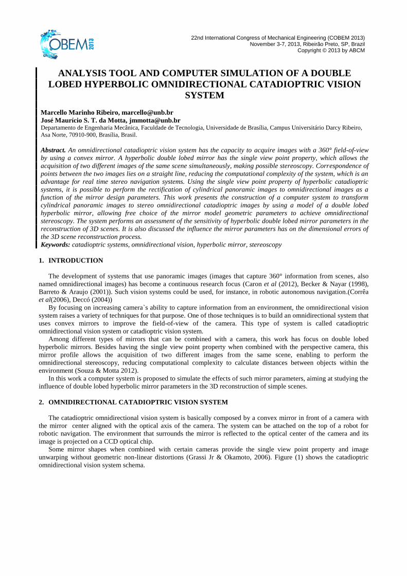
The catadioptric omnidirectional vision system is basically composed by a convex mirror in front of a camera with
the mirror center aligned with the optical axis of the camera. The system can be attached on the top of a robot for
robotic navigation. The environment that surrounds the mirror is reflected to the optical center of the camera and its
image is projected on a CCD optical chip.
Some mirror shapes when combined with certain cameras provide the single view point property and image
unwarping without geometric non-linear distortions (Grassi Jr & Okamoto, 2006). Figure (1) shows the catadioptric
omnidirectional vision system schema.
Ribeiro, M. M., Motta, J. M. S. T. Analysis Tool and Computer Simulation of a Double Lobed Hyperbolic Omnidirectional Catadioptric Vision System
Figure 1. Catadioptric omnidirectional vision system schema.
2.1 Single View Point
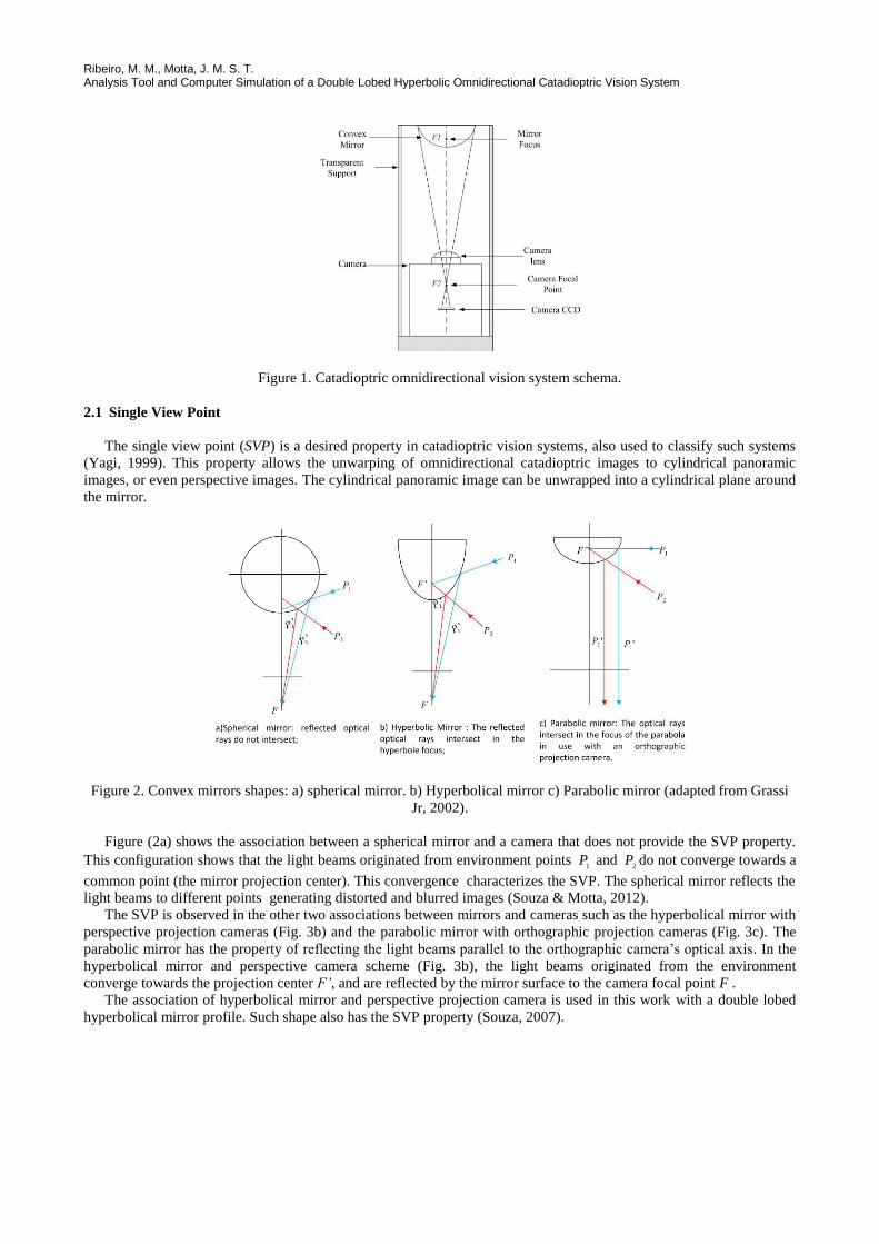
The single view point (SVP) is a desired property in catadioptric vision systems, also used to classify such systems
(Yagi, 1999). This property allows the unwarping of omnidirectional catadioptric images to cylindrical panoramic
images, or even perspective images. The cylindrical panoramic image can be unwrapped into a cylindrical plane around
the mirror.
Figure 2. Convex mirrors shapes: a) spherical mirror. b) Hyperbolical mirror c) Parabolic mirror (adapted from Grassi
Jr, 2002).
Figure (2a) shows the association between a spherical mirror and a camera that does not provide the SVP property.
This configuration shows that the light beams originated from environment points 1
P and 2
P do not converge towards a
common point (the mirror projection center). This convergence characterizes the SVP. The spherical mirror reflects the
light beams to different points generating distorted and blurred images (Souza & Motta, 2012).
The SVP is observed in the other two associations between mirrors and cameras such as the hyperbolical mirror with
perspective projection cameras (Fig. 3b) and the parabolic mirror with orthographic projection cameras (Fig. 3c). The
parabolic mirror has the property of reflecting the light beams parallel to the orthographic camera’s optical axis. In the
hyperbolical mirror and perspective camera scheme (Fig. 3b), the light beams originated from the environment
converge towards the projection center F’, and are reflected by the mirror surface to the camera focal point F .
The association of hyperbolical mirror and perspective projection camera is used in this work with a double lobed
hyperbolical mirror profile. Such shape also has the SVP property (Souza, 2007).
22nd International Congress of Mechanical Engineering (COBEM 2013) November 3-7, 2013, Ribeirão Preto, SP, Brazil
2.2 Hyperbolic mirror design
A hyperbole can be described by two mirrored curves disconnected formed by the intersection between a conical
surface and a plane. As a result, a set of Cn(x,y) points can be drawn, such that the difference between the line segments
d1 and d2 is constant, as shown in Fig. (3).
Figure 3. Hyperbole (adapted from Souza 2007).
The hyperbole curve is defined by.
1)()(
2
2
2
2
b
jx
a
ky, (1)
where a and b are the hyperbole semi-axes that have their center located in (j, k). If the hyperbole center is at the
system origin (j=0, k=0), Eq. (1) can be simplified to
12
2
2
2
b
x
a
y
(2)
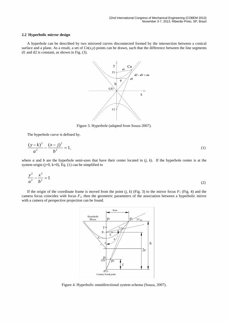
If the origin of the coordinate frame is moved from the point (j, k) (Fig. 3) to the mirror focus F1 (Fig. 4) and the
camera focus coincides with focus F2, then the geometric parameters of the association between a hyperbolic mirror
with a camera of perspective projection can be found.
Figure 4. Hyperbolic omnidirectional system schema (Souza, 2007).
Ribeiro, M. M., Motta, J. M. S. T. Analysis Tool and Computer Simulation of a Double Lobed Hyperbolic Omnidirectional Catadioptric Vision System
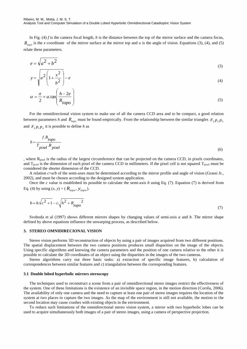
In Fig. (4) f is the camera focal length, h is the distance between the top of the mirror surface and the camera focus,
topoR is the x coordinate of the mirror surface at the mirror top and α is the angle of vision. Equations (3), (4), and (5)
relate these parameters.
22 bae (3)
e
b
xay
2
21.2
(4)
topoR
eha
2tan.
2
(5)
For the omnidirectional vision system to make use of all the camera CCD area and to be compact, a good relation
between parameters h and topoR must be found empirically. From the relationship between the similar triangles
322 ppF
and 412 ppF it is possible to define h as
pixelR
pixelT
topoRf
h.
.
(6)
, where Rpixel is the radius of the largest circumference that can be projected on the camera CCD, in pixels coordinates,
and Tpixel is the dimension of each pixel of the camera CCD in millimeters. If the pixel cell is not squared Tpixel must be
considered the shorter dimension of the CCD.
A relation c=a/b of the semi-axes must be determined according to the mirror profile and angle of vision (Grassi Jr.,
2002), and must be chosen according to the designed system application.
Once the c value is established its possible to calculate the semi-axis b using Eq. (7). Equation (7) is derived from
Eq. (4) by using (x, y) = (topoR ,
topoy ).
22.12.topo
Rhcchb (7)
Svoboda et al (1997) shows different mirrors shapes by changing values of semi-axis a and b. The mirror shape
defined by above equations influence the unwarping process, as described below.
3. STEREO OMNIDIRECIONAL VISION
Stereo vision performs 3D reconstruction of objects by using a pair of images acquired from two different positions.
The spatial displacement between the two camera positions produces small disparities on the image of the objects.
Using specific algorithms and knowing the camera parameters and the position of one camera relative to the other it is
possible to calculate the 3D coordinates of an object using the disparities in the images of the two cameras.
Stereo algorithms carry out three basic tasks: a) extraction of specific image features, b) calculation of
correspondences between similar features and c) triangulation between the corresponding features.
3.1 Double lobed hyperbolic mirrors steroscopy
The techniques used to reconstruct a scene from a pair of omnidirectional stereo images restrict the effectiveness of
the system. One of these limitations is the existence of an invisible space region, in the motion direction (Corrêa, 2006).
The availability of only one camera and the need to capture at least one pair of stereo images requires the location of the
system at two places to capture the two images. As the map of the environment is still not available, the motion to the
second location may cause crashes with existing objects in the environment.
To reduce such limitations of the omnidirectional stereo vision system, a mirror with two hyperbolic lobes can be
used to acquire simultaneously both images of a pair of stereo images, using a camera of perspective projection.
22nd International Congress of Mechanical Engineering (COBEM 2013) November 3-7, 2013, Ribeirão Preto, SP, Brazil
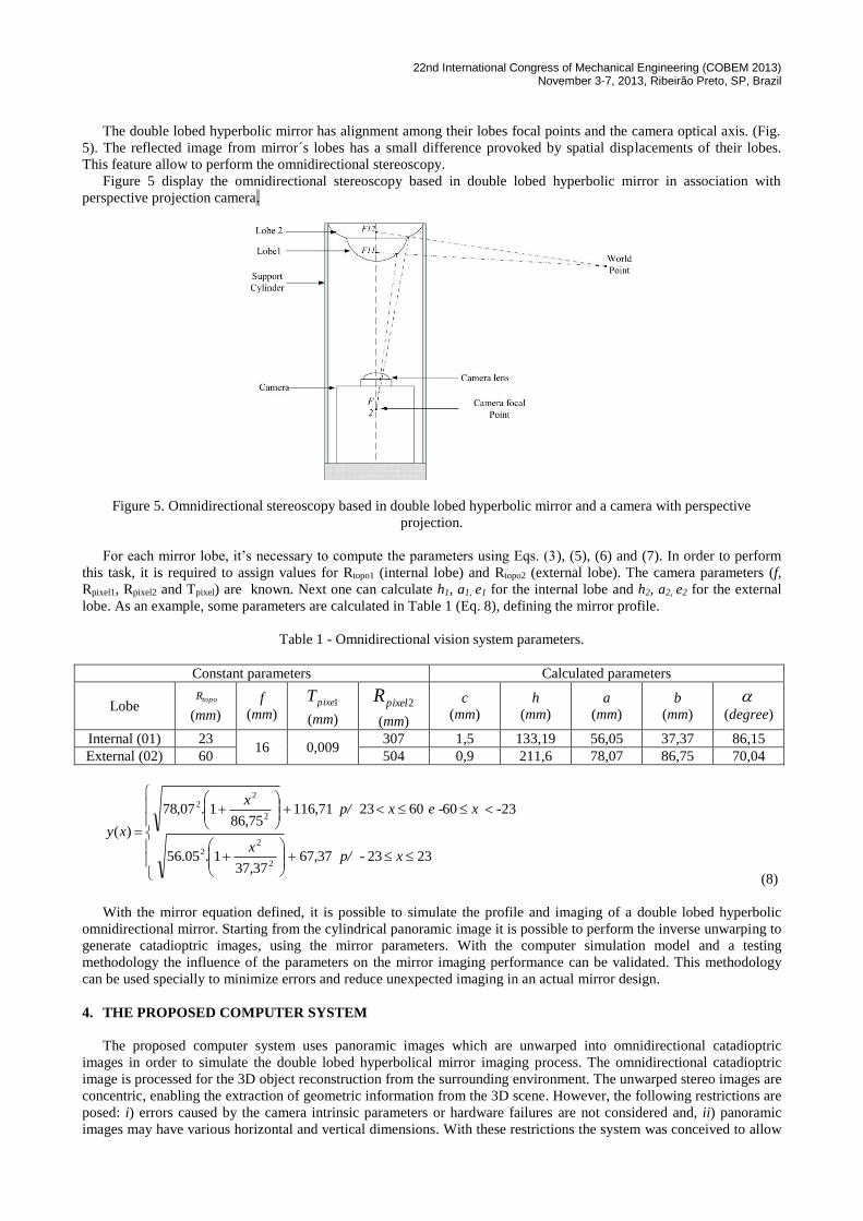
The double lobed hyperbolic mirror has alignment among their lobes focal points and the camera optical axis. (Fig.
5). The reflected image from mirror´s lobes has a small difference provoked by spatial displacements of their lobes.
This feature allow to perform the omnidirectional stereoscopy.
Figure 5 display the omnidirectional stereoscopy based in double lobed hyperbolic mirror in association with
perspective projection camera.
Figure 5. Omnidirectional stereoscopy based in double lobed hyperbolic mirror and a camera with perspective
projection.
For each mirror lobe, it’s necessary to compute the parameters using Eqs. (3), (5), (6) and (7). In order to perform
this task, it is required to assign values for Rtopo1 (internal lobe) and Rtopo2 (external lobe). The camera parameters (f,
Rpixel1, Rpixel2 and Tpixel) are known. Next one can calculate h1, a1, e1 for the internal lobe and h2, a2, e2 for the external
lobe. As an example, some parameters are calculated in Table 1 (Eq. 8), defining the mirror profile.
Table 1 - Omnidirectional vision system parameters.
Constant parameters Calculated parameters
Lobe topoR
(mm)
f
(mm) 1pixeT
(mm)
2pixelR
(mm)
c
(mm)
h
(mm)
a
(mm)
b
(mm)
(degree)
Internal (01) 23 16 0,009
307 1,5 133,19 56,05 37,37 86,15
External (02) 60 504 0,9 211,6 78,07 86,75 70,04
2323- 37,6737,37
1.05.56
23606023 71,11675,86
1.07,78
)(
2
22
2
22
xp/x
-x e -xp/x
xy
(8)
With the mirror equation defined, it is possible to simulate the profile and imaging of a double lobed hyperbolic
omnidirectional mirror. Starting from the cylindrical panoramic image it is possible to perform the inverse unwarping to
generate catadioptric images, using the mirror parameters. With the computer simulation model and a testing
methodology the influence of the parameters on the mirror imaging performance can be validated. This methodology
can be used specially to minimize errors and reduce unexpected imaging in an actual mirror design.
4. THE PROPOSED COMPUTER SYSTEM
The proposed computer system uses panoramic images which are unwarped into omnidirectional catadioptric
images in order to simulate the double lobed hyperbolical mirror imaging process. The omnidirectional catadioptric
image is processed for the 3D object reconstruction from the surrounding environment. The unwarped stereo images are
concentric, enabling the extraction of geometric information from the 3D scene. However, the following restrictions are
posed: i) errors caused by the camera intrinsic parameters or hardware failures are not considered and, ii) panoramic
images may have various horizontal and vertical dimensions. With these restrictions the system was conceived to allow
Ribeiro, M. M., Motta, J. M. S. T. Analysis Tool and Computer Simulation of a Double Lobed Hyperbolic Omnidirectional Catadioptric Vision System
parameter choices by the user such as f and Tpixel (camera parameters), Rtopo and Rpixel (to be used in unwarp process) and
c= a/b for each lobe.
The system input is a cylindrical panoramic image. To unwarp the input image the system offers two options to
generate the catadioptric image as defined in section 3, using the parameters of the double lobed hyperbolic mirror.
The features used by the system are image corners and edges. These features are simpler to detect and present in
most of simple objects.
The algorithm to extract image features applies a nonlinear median filter on the catadioptric images to attenuate the
effects of quantization generated for the unwarping process. Next, edge detection is performed (Ballard & Brown,
1992), followed by the corner detection by using the Harris algorithm (Harris & Stephens, 1998).
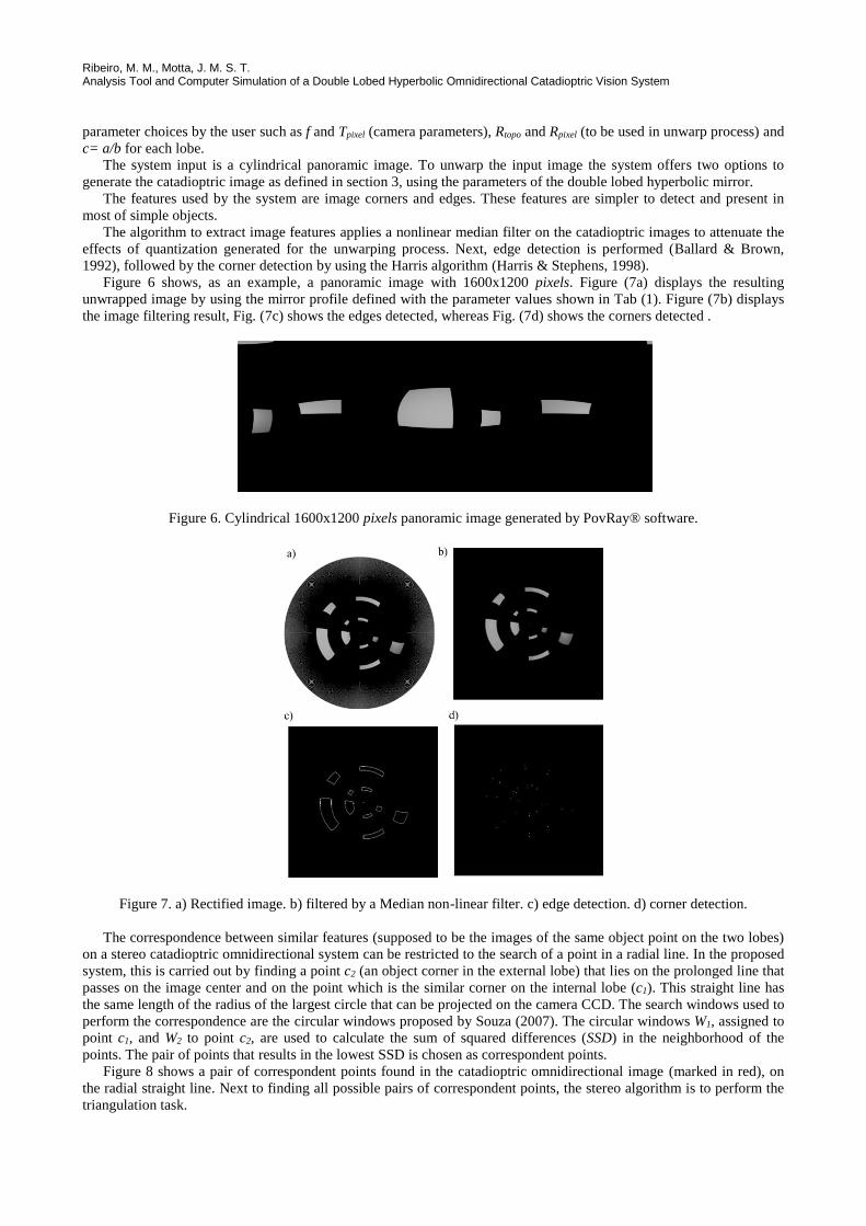
Figure 6 shows, as an example, a panoramic image with 1600x1200 pixels. Figure (7a) displays the resulting
unwrapped image by using the mirror profile defined with the parameter values shown in Tab (1). Figure (7b) displays
the image filtering result, Fig. (7c) shows the edges detected, whereas Fig. (7d) shows the corners detected .
Figure 6. Cylindrical 1600x1200 pixels panoramic image generated by PovRay® software.
Figure 7. a) Rectified image. b) filtered by a Median non-linear filter. c) edge detection. d) corner detection.
The correspondence between similar features (supposed to be the images of the same object point on the two lobes)
on a stereo catadioptric omnidirectional system can be restricted to the search of a point in a radial line. In the proposed
system, this is carried out by finding a point c2 (an object corner in the external lobe) that lies on the prolonged line that
passes on the image center and on the point which is the similar corner on the internal lobe (c1). This straight line has
the same length of the radius of the largest circle that can be projected on the camera CCD. The search windows used to
perform the correspondence are the circular windows proposed by Souza (2007). The circular windows W1, assigned to
point c1, and W2 to point c2, are used to calculate the sum of squared differences (SSD) in the neighborhood of the
points. The pair of points that results in the lowest SSD is chosen as correspondent points.
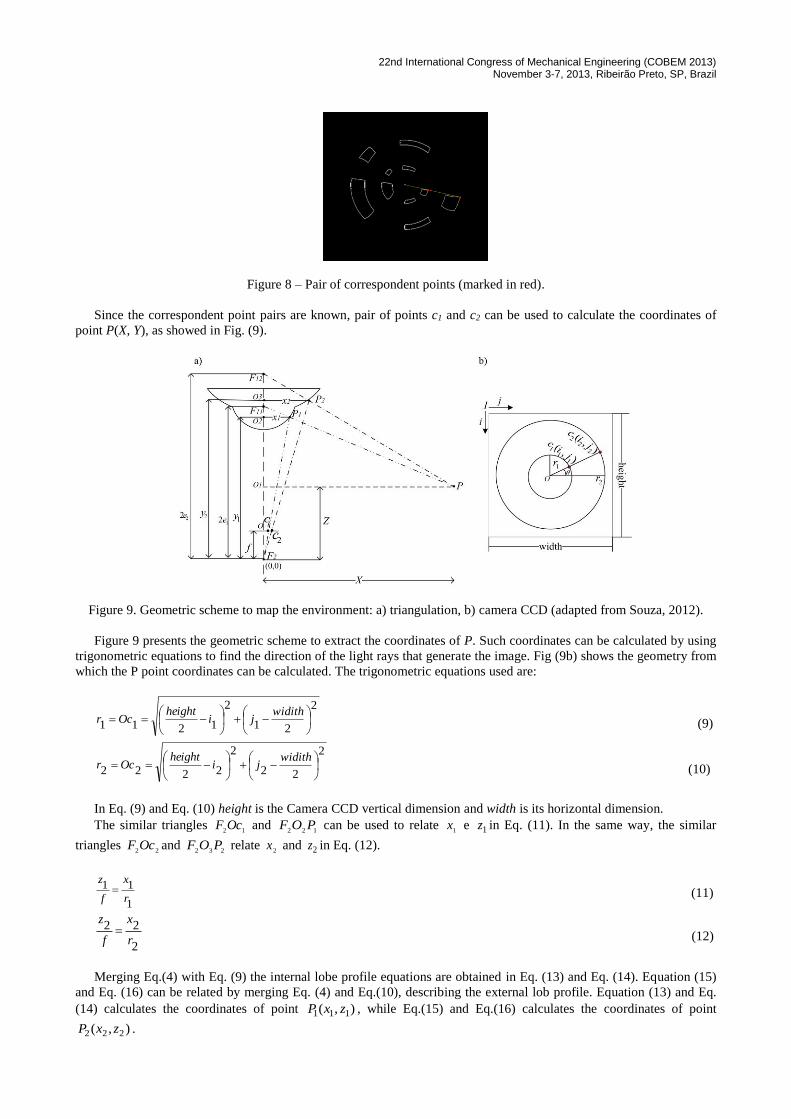
Figure 8 shows a pair of correspondent points found in the catadioptric omnidirectional image (marked in red), on
the radial straight line. Next to finding all possible pairs of correspondent points, the stereo algorithm is to perform the
triangulation task.
22nd International Congress of Mechanical Engineering (COBEM 2013) November 3-7, 2013, Ribeirão Preto, SP, Brazil
Figure 8 – Pair of correspondent points (marked in red).
Since the correspondent point pairs are known, pair of points c1 and c2 can be used to calculate the coordinates of
point P(X, Y), as showed in Fig. (9).
Figure 9. Geometric scheme to map the environment: a) triangulation, b) camera CCD (adapted from Souza, 2012).
Figure 9 presents the geometric scheme to extract the coordinates of P. Such coordinates can be calculated by using
trigonometric equations to find the direction of the light rays that generate the image. Fig (9b) shows the geometry from
which the P point coordinates can be calculated. The trigonometric equations used are:
2
21
2
1211
widithji
heightOcr (9)
2
22
2
2222
widithji
heightOcr (10)
In Eq. (9) and Eq. (10) height is the Camera CCD vertical dimension and width is its horizontal dimension.
The similar triangles 12
OcF and 122
POF can be used to relate 1
x e 1z in Eq. (11). In the same way, the similar
triangles 22
OcF and 232
POF relate 2
x and 2z in Eq. (12).
1
11
r
x
f
z (11)
2
22
r
x
f
z
(12)
Merging Eq.(4) with Eq. (9) the internal lobe profile equations are obtained in Eq. (13) and Eq. (14). Equation (15)
and Eq. (16) can be related by merging Eq. (4) and Eq.(10), describing the external lob profile. Equation (13) and Eq.
(14) calculates the coordinates of point ),( 111 zxP , while Eq.(15) and Eq.(16) calculates the coordinates of point
),( 222 zxP .
Ribeiro, M. M., Motta, J. M. S. T. Analysis Tool and Computer Simulation of a Double Lobed Hyperbolic Omnidirectional Catadioptric Vision System
21
21
21
2
112
12
12
12
12
12
111
1rabf
brraerbfabfe
x
(13)
1
11 r
fxz (14)
22
22
22
2
222
22
22
22
22
22
222
2rabf
brraerbfabfe
x
(15)
2
22 r
fxz (16)
Similarity of triangles also can be used to relate the coordinates of point P(X, Y) with the coordinates of the points
),( 111 zxP and ),( 222 zxP . Using the similar triangles 111POF and 2111 OPF one can formulate Eq. (17) that express the
relationship between P(X, Z) and ),( 111 zxP . In the same way, the similarity of triangles 112POF and F12PO1 is
formulated by Eq. (18), that relates P(X, Z) and ),( 222 zxP .
112
12
1ze
Ze
x
X
(17)
222
22
2ze
Ze
x
X
(18)
Merging Eq. (17) and Eq. (18) yields Eq. (19) and Eq.(20), the point P coordinates.
)11
2(2
)21
2(1
)12
(21
2
zexzex
eexxX
(19)
2
)22
2(
22
x
zeXeZ
(20)
For each pair of correspondent image points, the system calculates the coordinates (X, Z) of selected points of an
object within the environment with origin at the camera focus point, making possible the construction of an
environment map. By using such coordinates and the angle θ associated to each point (Fig. 9b), the distance between
the mirror focus and an object point P(X,) in polar coordinates can be calculated, and then making possible to
construct a map of points Pn(Xn,n) (Fig. 10) with n < ∞.
5. METHODOLOGY TO EVALUATE RESULTS
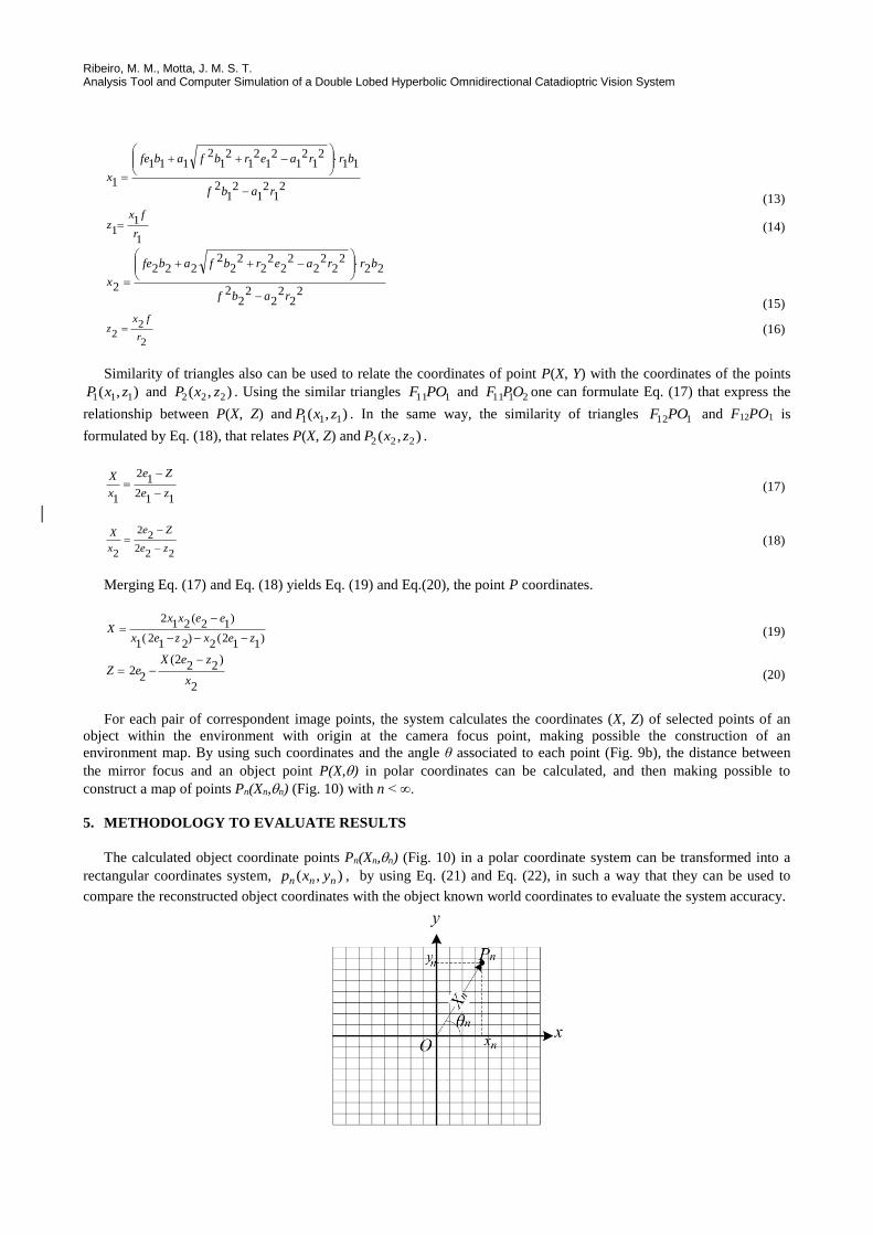
The calculated object coordinate points Pn(Xn,n) (Fig. 10) in a polar coordinate system can be transformed into a
rectangular coordinates system, ),( nnn yxp , by using Eq. (21) and Eq. (22), in such a way that they can be used to
compare the reconstructed object coordinates with the object known world coordinates to evaluate the system accuracy.
22nd International Congress of Mechanical Engineering (COBEM 2013) November 3-7, 2013, Ribeirão Preto, SP, Brazil
Figure 10. Transformation between polar and rectangular coordinates.
)cos( nnn Xx (21)
)( nnn senXy (22)
Since Pw(xw, yw, zw) and ),( nnn yxp are known, the reconstruction error can be calculated by using the Euclidean
distance d between np and Pw (point coordinate in the environment) as
22),( )()(
nnnn PPPp yzyxd (23)
Equation (23) shows the reconstruction errors and can be used to estimate the measurement accuracy of the
proposed system. In this work, the Z coordinate (vertical distance between the system focal point and the environment
point) was not used for error calculations since no vertical displacement was programmed in the experiments.
To calculate the error results, a simulated environment with a ray tracing tool PovRay® was created. Such
environment was designed to evaluate the system performance and to calculate the distance between scene points and
the system focal point, according to the mirror parameters.
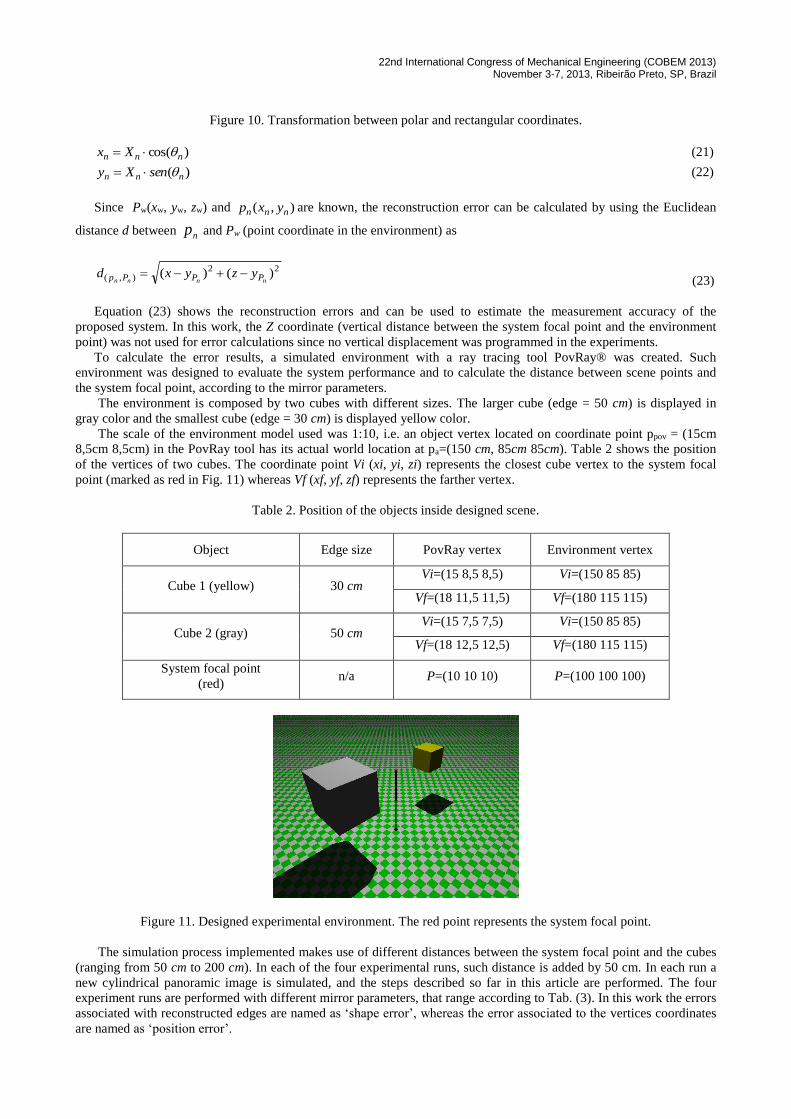
The environment is composed by two cubes with different sizes. The larger cube (edge = 50 cm) is displayed in
gray color and the smallest cube (edge = 30 cm) is displayed yellow color.
The scale of the environment model used was 1:10, i.e. an object vertex located on coordinate point ppov = (15cm
8,5cm 8,5cm) in the PovRay tool has its actual world location at pa=(150 cm, 85cm 85cm). Table 2 shows the position
of the vertices of two cubes. The coordinate point Vi (xi, yi, zi) represents the closest cube vertex to the system focal
point (marked as red in Fig. 11) whereas Vf (xf, yf, zf) represents the farther vertex.
Table 2. Position of the objects inside designed scene.
Object Edge size PovRay vertex Environment vertex
Cube 1 (yellow) 30 cm Vi=(15 8,5 8,5) Vi=(150 85 85)
Vf=(18 11,5 11,5) Vf=(180 115 115)
Cube 2 (gray) 50 cm Vi=(15 7,5 7,5) Vi=(150 85 85)
Vf=(18 12,5 12,5) Vf=(180 115 115)
System focal point
(red) n/a P=(10 10 10) P=(100 100 100)
Figure 11. Designed experimental environment. The red point represents the system focal point.
The simulation process implemented makes use of different distances between the system focal point and the cubes
(ranging from 50 cm to 200 cm). In each of the four experimental runs, such distance is added by 50 cm. In each run a
new cylindrical panoramic image is simulated, and the steps described so far in this article are performed. The four
experiment runs are performed with different mirror parameters, that range according to Tab. (3). In this work the errors
associated with reconstructed edges are named as ‘shape error’, whereas the error associated to the vertices coordinates
are named as ‘position error’.
Ribeiro, M. M., Motta, J. M. S. T. Analysis Tool and Computer Simulation of a Double Lobed Hyperbolic Omnidirectional Catadioptric Vision System
Table 3. Mirror range parameters.
Parameter Mín value Average Max value Increment
1topoR (mm) 15 37,5 60 5
2topoR (mm) 45 67,5 90 5
1pixelR (pixels) 130 180 220 10
2pixelR
(pixels)
300 425 550 25
111 / bac 0,5 1,4 2,3 0.2
222 / bac 0,5 1,4 2,3 0.2
When a parameter is to be varied in the simulation analysis, the average value of the remaining parameters shown
in Tab. 3 are taken as constants in a run. For example, when 2c is in focus, the others parameters are taken as their
average values displayed in Tab. (3). The set of camera’s intrinsic parameters were fixed in f= 16 mm and
009,0pixelT mm.
6. ANALYSIS OF THE RESULTS
The results obtained from the experiments to analyze the system accuracy by varying the catadioptric double lobed
mirror parameters show that the calculated errors have an expected behavior, reflecting the ability of the proposed
system to maintain the geometric shapes of the environment’s objects during the reconstruction task. However,
variations of the object distance within the scene appear to be a restriction for proper applications of the omnidirectional
system.
It was observed that a factor that can reduce the system accuracy by increasing the quantization effects (Fig. 8a) is
the ratio between the vertical resolution of the cylindrical panoramic and the 2pixelR parameter that defines the
catadioptric image size. Equation 24 proposes a ratio that generates satisfactory results, minimizing the quantization
effects.
32
pn
pixel
VR
(24)
By using a value for Rpixel2 that satisfies Eq. (23), the image process that applies a median filter to the image can be
skipped, reducing the computational cost of the system.
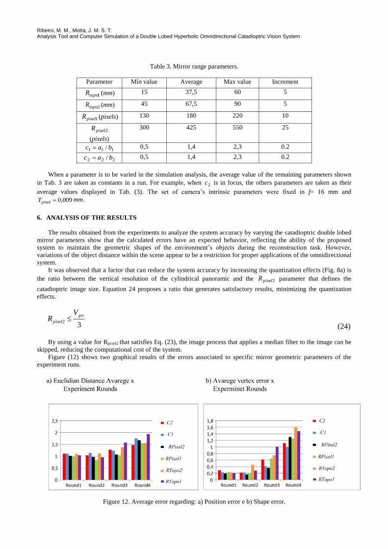
Figure (12) shows two graphical results of the errors associated to specific mirror geometric parameters of the
experiment runs.
Figure 12. Average error regarding: a) Position error e b) Shape error.
22nd International Congress of Mechanical Engineering (COBEM 2013) November 3-7, 2013, Ribeirão Preto, SP, Brazil
It can be observed that Rtopo2 , Rpixel1 and c2 have more effect on the position errors than Rtopo1 , Rpixel2 and c1. That
means, their variation (Rtopo2, Rpixel1 and c2) produce larger variations in the position errors of the vertices. This effect
can also be observed when one looks to the shape errors (edge errors), in special Rpixel1.
The variation of Rtopo1 and Rtopo2 shows that by increasing the hyperbole base, so varying the mirror lobe profile, the
errors are reduced. This happens because data obtained from the scene by using larger mirrors brings about more
information to the camera CCD. It can be seen that there is a larger error variation as a consequence of variations of
Rtopo1 than with Rtopo2 in all experiment runs.
Regarding the variation of the parameters Rpixel1 and Rpixel2, the results show that the errors are reduced by increasing
the value of Rpixel2, but Rpixel1 has smaller effect on errors when its value are median (ranging from 160 to 190 pixels). It
can be observed that when the area of internal lobe of the catadioptric image exceeds 50% of the whole circumference
radius, the efficiency of the system decreases.
Concerning the variation of the parameters c1 and c2, it is shown that there is a tendency to reduction in errors when
their values ranges around their median values and worsen errors when their values are in the extremes of their range. In
other words, the best results are achieved when their values ranges from 0.9 to 1.7. Such parameters have influence on
the mirror curvature and highlight that lobes with accentuated curvatures, in general, increase the errors. However, the
results show that the parameter c1 must be larger than c2. The constraint 21 5,1 cc has shown to produce satisfactory
results.
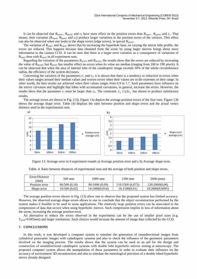
The average errors are shown in Fig. (13). Figure 13a depicts the average position errors of the four runs. Figure 13b
shows the average shape error. Table (4) displays the ratio between position and shape errors and the actual vertex
distance used in the experimental runs.
Figure 13. Average error in 4 experiment rounds a) Average position error and e b) Average shape error.
Table. 4. Ratio between distances of experimental runs and the average of both position and shape errors.
Error/Distance
(mm) 500 mm 1000 mm 1500 mm 2000 (mm)
Position error 80:500 (0,16) 90:1000 (0,09) 110:1500 (0,073) 120:2000(0,06)
Shape error 10:500 (0,02) 14:1000(0,014) 16:1500(0,01) 19:2000(0,0095)
The average position errors shown in Fig. (13) allow one to observe that the proposed system has limited accuracy.
However, the observed average shape errors allows to one to conclude that the object reconstruction performed by the
system makes it feasible to be used in some applications. The relatively large position errors can be associated to the
compression of data that occurs when using hyperbolic mirrors. Such compression implies in loss of information about
the scene, increasing the average position error.
An alternative to reduce the errors observed in the experiments can be the use of smaller pixel sizes (e.g.
Tpixel=0.005mm) and larger resolutions. Such choices would increase the amount of image data collected by the CCD.
7. CONCLUSIONS
In this work, it was developed a computer system to simulate the generation of omnidirectional images from
cylindrical panoramic images with cadadioptric systems and also to check the influence of the geometric parameters
involved on the imaging process. The results shows that the system can be used as an aid for the design and
construction of omnidirectional catadioptric systems with double lobe hyperbolic mirrors aiming at stereoscopy. The
proposed computer system allows the manipulation of these parameters in order to evaluate their influence on the
accuracy of environment 3D reconstruction and also to simulate the metrological precision of a double lobed hyperbolic
mirror already designed.
Ribeiro, M. M., Motta, J. M. S. T. Analysis Tool and Computer Simulation of a Double Lobed Hyperbolic Omnidirectional Catadioptric Vision System
Four runs of experiments were proposed to validate the use of the developed system. This validation involved the
design of a second environment using the rendering tool PovRay®. In each run of experiments variations were
performed in the omnidirectional system parameters. At each change of parameters, position and shape errors at
different visible vertex or edge by the system were calculated. Along the experiments, the objects within the
environment were displaced and parameters recalculated.
It was observed that Rtopo2, Rpixel1 and c2 have more influence in the scene reconstruction than Rtopo1, Rpixel2 and c1. It
can be also observed that the effect of the scene object distance from the mirror system has shown to be an important
restriction to an omnidirectional vision system based on hyperbolic double lobed mirrors.
8. REFERENCES
Ballard, D. H., & Brown, C. M., 1982. "Computer Vision". Englewood Cliffs, New Jersey, USA: Prantice-Hall.
Harris, C., & Stephens, M., 1988. "A Combined Corner and Edge Detector". Proceedings of the 4th Alvey Vision
Conference, p. 147 -151.
Barreto, J. P., & Araujo, H., 2001. "Issue on the Geometry of Central Catadioptric Image Formation". Computer Vision
and Pattern Recognition (CVPR 2001) Vol. 2, (pp. II - 422-427). Kawai, Havai.
Beker, S., & Nayar, S. K.., 1998. "A Theory of Catadioptric Image Formation". International Conference on Computer
Vision, p. 213-220. Bombay, India.
Caron, G., Mouaddib, E. M., and Marchand, E., 2012, "3D Model Based Tracking For Omnidirectional Vision: A New
Spherical Appoarch". Robotics and Autonomous Systems, 60(8), 1056-1068.
Corrêa, F. R., Guizilini, V. C., & Okmoto-Jr., J. (2006). "Omndircetional Stereovision system with tow-lobe Hyperbolic
Mirror for robot navegation". ABCM Symposium Series in Mechatronics, Vol. 2, pp. 653-660.
Deccó, C. C. (2004). "Construçã de Mapas de Ambiente para Navegação de Robôs Móveis com Visão Omnidirecional
Estéreo". Tese (Doutorado). São Paulo, SP, Brasil.
Grassi Jr, V., 2002. "Sistema de Visão Omnidirecional Aplicado no Controle de Robôs Móveis". Dissertação (
Mestrado). São Paulo, SP.
Grassi Jr, V., and Okamoto Jr, J. 2006. "Development of an Omnidiretional Vision System". Journal of the Brazilian
Society of Mechanical Sciences and Engineering Vol. 28, No.1, 658-68.
Harris, C., & Stephens, M. (1988). "A Combined Corner and Edge Detector". Proceedings of the 4th Alvey Vision
Conference, pp. 147 -151.
Souza, G.G., 2007. "Simulation and Design of an Omnidirectional Catadioptric Stereo Vision System With a
Hyperbolic Double Lobe Mirror For Environment Mapping From Mobile Robots". 19th International Congress of
Mechanical Engineering (COBEM). Brasilia.
Souza, G.G., and Motta, J.M.S.T., 2012 “Simulation and Design of an omnidirectional catadioptric stereo vision system
with a hyperbolic double lobed mirror for environment mapping from mobile robots.”In ABCM Symposium Series in
Mechatronics, Vol. 5, p. 9-18.
Svoboda, T., Pajdla, T., and Hilavac, V., 1997. "Central Panoramic Cameras: Geometry and Design". Czech Technical
University, Faculty of Eletrical Engineering, Center for Machine Perception, Praga, Czech Technical University.
Yagi, Y., 1999. "Omnidirectional Sensing and Its Applications". IEICE Trasnections on Information and Systems, p.
568-579. VE82-D, Nº 3.
9. RESPONSIBILITY NOTICE
The authors are the only responsible for the printed material included in this paper.
Related Documents
![Free Space Detection from Catadioptric Omnidirectional Images … · Using a vision system inspired by insects, navigation algorithms for the au-tonomous robot are proposed [6,7,9,17,19].](https://static.cupdf.com/doc/110x72/5ed69888843ed9152066ae1c/free-space-detection-from-catadioptric-omnidirectional-images-using-a-vision-system.jpg)