Analysis, search, and classification for reflective ring-field projection systems Matthieu F. Bal, Florian Bociort, and Joseph J. M. Braat Extreme ultraviolet EUV lithography uses reflective ring-field projection systems. Geometrical ob- struction limits the possible system configurations to small domains of the parameter space. We present an analysis, a search method, and a classification of these unobstructed domains. The exhaustive search method based on paraxial analysis provides an effective means for determining all possible design forms and for finding useful starting configurations for optimization. The approach is validated through comparison with finite ray tracing. © 2003 Optical Society of America OCIS codes: 080.2740, 110.3960, 340.7440. 1. Introduction Refractive lithographic systems experienced an im- pressive evolution over the past decades. However, the absorption in the lens material makes a further decrease of the wavelength of the radiation impossible. Extreme ultraviolet EUV lithography utilizes mir- rors and is a promising candidate to fulfill the contin- uous demand for ever-decreasing features on silicon wafers in the integrated circuit industry. The use of mirrors may lead to obstruction: Rays may be blocked by surfaces they were supposed to pass. The known EUV designs are ring-field scanning systems, which are highly corrected within the arched strip. The stringent optical performance conditions demanded in the projection system include a root-mean-square rms wave-front error smaller than 50 in image space. For correction of third- and higher-order aberrations, many optimization variables in the form of aspheric surface coefficients are required. In this paper we show how severe the obstruction-free-system requirement is. Owing to the large number of variables and constraints in- volved, choosing unobstructed starting configura- tions for subsequent optimization is a nontrivial issue in EUV system design. This choice is often based on existing experience and patent literature. 1–17 Com- pared with other types of optical system, the amount of experience in the field of EUV projection systems is, at present, still limited. With the search method presented in this paper, we demonstrate how the requirement of absence of obstruction can be used to systematically generate starting configurations for optimization. The theory section starts with a formulation of the special requirements for the reflective ring-field pro- jection systems. We describe how these require- ments can be implemented in the paraxial system model. Appendix A gives a more elaborate deriva- tion of the constrained paraxial model of a reflective projection system. In the theory section we also present our classification based on the angle of inci- dence of the principal ray on the mirrors. The implementation section demonstrates our use of the paraxial model. With the aid of software de- veloped by us, we look at the consequences of changes in intermediate distances between surfaces, curva- tures of mirrors, intersection heights of the chief ray with the mirrors, etc., in the paraxial constrained model. We also show results of systematic searches for unobstructed paraxial configurations and of two- dimensional analyses of the solution space. The two-dimensional analyses that use paraxial and fi- nite rays show how properties such as the wave-front error change in the solution space. With our sys- tematic exhaustive search method, we can find vir- tually all useful solution domains of systems. In the final section we illustrate the possibilities of our search method by presenting search results for four-, six-, and eight-mirror systems. Our searches for four- and six-mirror systems show that the most promising classes are already known. For eight- The authors are with Delft University of Technology, Lorentzweg 1, Delft 2628 CJ, The Netherlands. M. F. Bal’s e-mail address is [email protected]. Received 24 June 2002; revised manuscript received 23 January 2003. 0003-693503132301-11$15.000 © 2003 Optical Society of America 1 May 2003 Vol. 42, No. 13 APPLIED OPTICS 2301

Welcome message from author
This document is posted to help you gain knowledge. Please leave a comment to let me know what you think about it! Share it to your friends and learn new things together.
Transcript

Analysis, search, and classification for reflectivering-field projection systems
Matthieu F. Bal, Florian Bociort, and Joseph J. M. Braat
Extreme ultraviolet �EUV� lithography uses reflective ring-field projection systems. Geometrical ob-struction limits the possible system configurations to small domains of the parameter space. We presentan analysis, a search method, and a classification of these unobstructed domains. The exhaustive searchmethod based on paraxial analysis provides an effective means for determining all possible design formsand for finding useful starting configurations for optimization. The approach is validated throughcomparison with finite ray tracing. © 2003 Optical Society of America
OCIS codes: 080.2740, 110.3960, 340.7440.
1. Introduction
Refractive lithographic systems experienced an im-pressive evolution over the past decades. However,the absorption in the lens material makes a furtherdecrease of the wavelength of the radiation impossible.Extreme ultraviolet �EUV� lithography utilizes mir-rors and is a promising candidate to fulfill the contin-uous demand for ever-decreasing features on siliconwafers in the integrated circuit industry. The use ofmirrors may lead to obstruction: Rays may beblocked by surfaces they were supposed to pass.
The known EUV designs are ring-field scanningsystems, which are highly corrected within thearched strip. The stringent optical performanceconditions demanded in the projection system includea root-mean-square �rms� wave-front error smallerthan ��50 in image space. For correction of third-and higher-order aberrations, many optimizationvariables in the form of aspheric surface coefficientsare required. In this paper we show how severe theobstruction-free-system requirement is. Owing tothe large number of variables and constraints in-volved, choosing unobstructed starting configura-tions for subsequent optimization is a nontrivial issuein EUV system design. This choice is often based onexisting experience and patent literature.1–17 Com-
The authors are with Delft University of Technology, Lorentzweg1, Delft 2628 CJ, The Netherlands. M. F. Bal’s e-mail address [email protected].
Received 24 June 2002; revised manuscript received 23 January2003.
0003-6935�03�132301-11$15.00�0© 2003 Optical Society of America
pared with other types of optical system, the amountof experience in the field of EUV projection systemsis, at present, still limited. With the search methodpresented in this paper, we demonstrate how therequirement of absence of obstruction can be used tosystematically generate starting configurations foroptimization.
The theory section starts with a formulation of thespecial requirements for the reflective ring-field pro-jection systems. We describe how these require-ments can be implemented in the paraxial systemmodel. Appendix A gives a more elaborate deriva-tion of the constrained paraxial model of a reflectiveprojection system. In the theory section we alsopresent our classification based on the angle of inci-dence of the principal ray on the mirrors.
The implementation section demonstrates our useof the paraxial model. With the aid of software de-veloped by us, we look at the consequences of changesin intermediate distances between surfaces, curva-tures of mirrors, intersection heights of the chief raywith the mirrors, etc., in the paraxial �constrained�model. We also show results of systematic searchesfor unobstructed paraxial configurations and of two-dimensional analyses of the solution space. Thetwo-dimensional analyses that use paraxial and fi-nite rays show how properties such as the wave-fronterror change in the solution space. With our sys-tematic exhaustive search method, we can find vir-tually all useful solution domains of systems.
In the final section we illustrate the possibilities ofour search method by presenting search results forfour-, six-, and eight-mirror systems. Our searchesfor four- and six-mirror systems show that the mostpromising classes are already known. For eight-
1 May 2003 � Vol. 42, No. 13 � APPLIED OPTICS 2301

mirror systems, however, some new classes, notfound in patent publications, seem promising.
2. Theory
The rotationally symmetric aspheric mirrors image aring-shaped object. An EUV system demands ahigh resolution, a high throughput, small distortion,and image-side telecentricity of the reflective projec-tion optics. Many optimization variables are neededin order to obtain a projection system withdiffraction-limited imaging. The design variables ofEUV projection optics include the positions of theobject and image planes, the separations betweenmirrors, the curvatures, and the coefficients describ-ing the profile of the surfaces. All these variablesinfluence the numerous image aberrations, whichmust be reduced to low values for good performance.Introducing more mirrors or employing aspheric sur-faces can increase the number of variables. Thesesurfaces should have small aspheric departures withrespect to the base surface. The typical upper limitof these departures is 10 �m. In that usually thereflection of an EUV mirror, coated with special mul-tilayers, does not exceed 70%, the advantages of moremirrors used �i.e., more optimization variables andtherefore a larger achievable numerical aperture�have to be weighed against the disadvantages such asa decreased throughput and increased complexity ofthe EUV system.
For determining an unobstructed starting point fora design, we use the limiting case of the paraxialapproximation. Paraxial analysis has already beenapplied successfully to EUV design by Lerner et al.18
By comparing the paraxial and finite ray paths onsystem drawings, we noticed that paraxial ray trac-ing agrees well with finite ray tracing for the purposeof obstruction analysis, especially when the aberra-tions are small. When using the paraxial approxi-mation, we ignore the aspheric coefficients and,consequently, drastically reduce the dimensionalityof the search space. Howard and Stone19–22 use fornonrotational symmetric systems a comparable butmore complex Hamiltonian approach.23
A. Obstruction
Obstruction occurs when rays that should propagatefreely between two surfaces are accidentally blockedby a third surface. Obstruction deteriorates the op-tical resolution and should therefore be avoided. Toevaluate whether a system with N mirrors is ob-structed, we examine the combinations of beam frag-ments between successive surfaces i and i � 1�including object and image planes� and mirrors j forall possible pairs of i and j. The combination of abeam segment and a mirror is shown in Fig. 1. Thelowermost and uppermost rays, starting from the ob-ject, determine the size of the beam. These two rays�called the extreme meridional rays� intersect mirrorj in two points Pj,0 and Pj,1 and thus delimit the usefulpart of the mirror. The heights of these points aredenoted by yj,0 and yj,1, and their locations along theoptical axis are denoted by zj,0 and zj,1, respectively.
The coordinates of the intersections Pi,0, Pi,1, Pi�1,0,and Pi�1,1 of the two extreme meridional rays withmirror i and mirror i � 1 are denoted similarly. Weextend surface j to find the intersection points Pj,0�and Pj,1� �with the coordinates yj,0�, zj,0� and yj,1�, zj,1��of the two extreme meridional rays propagating be-tween mirrors i and i � 1 with mirror j. These fourcoordinates can be obtained when the equation issolved:
yi,k �yi�1,k � yi,k
zi�1,k � zi,k� zj,k� � zi,k� � yj,0 �
yj,1 � yj,0
zj,1 � zj,0
� � zj,k� � zj,0� � yj,k�, (1)
with k � 0 or 1. We distinguish among three posi-tions of mirror j relative to the position of the beam:
1. Both yj,0 and yj,1 are larger than yj,0� and yj,1�;therefore the beam passes beneath the mirror.
2. Both yj,0 and yj,1 are smaller than yj,0� and yj,1�;therefore the beam passes over the mirror.
3. The beam is obstructed because at least one ofthe points Pj,0� and Pj,1� belongs to the used part ofmirror j. Obstruction occurs when the logical ex-pressions
∨1
k�0(yj,k� � � yj,0, yj,1� � ∨
1
k�0� zj,k� � � zj,0, zj,1� (2)
are true, where ∨ m denotes the logical summation �or�extended over all values of integer m. The obstruc-tion of the beam is either real or fictitious, dependingon whether the mirror j intersects the beam or thebeam’s extension within or outside, respectively, thesegment between the two mirrors i and i � 1. InFig. 2, different situations of obstruction are shown.The real obstructions can be distinguished from theharmless fictitious obstructions by examination ofthe logical expressions
∨1
k�0� zj,k� � � zi,k, zi�1,k� � ∨
1
k�0� yj,k� � � yi,k, yi�1,k), (3)
which are true in case of real obstructions.
Fig. 1. When mirrors unintentionally intersect and block rays,the system is obstructed. In the figure, points Pi,0, Pi,1, Pi�1,0,Pi�1,1, Pj,0, and Pj,1 are the intersections of the extreme meridionalrays with the surfaces. The thick lines are the reflective surfaces,and, in the gray points, the beam propagates from mirror i tomirror i � 1.
2302 APPLIED OPTICS � Vol. 42, No. 13 � 1 May 2003

This special case of the evaluation of the occurrence ofobstruction with one mirror and one beam segmentleads to a general logical expression for the occur-rence of obstruction O in a mirror system:
O � ∨N
i�0∨N
j1jiji�1
∨1
k�0� yj,k� � � yj,0, yj,1�
∧ � yj,k� � � yi,k, yi�1,k�, (4)
where ∧ represents the logical multiplication �and�.
B. Constraints
The high-throughput requirement leads to a largering width, to permit high scanning or stepping ve-locities. The distortion within this ring should bevery small, not exceeding a few nanometers. Thesystem should be as close to telecentricity as possibleto minimize distortion effects as a consequence ofdefocusing. Otherwise, slight axial shifts of themask or wafer plane from their ideal positions cancause unacceptable transverse image displacements.However, because the mask is also reflective and il-luminated, the projection system can only be quasi-telecentric on the mask side �i.e., either the upper orthe lower extreme meridional ray must be almosthorizontal�.
The required imaging quality demands a rmswave-front error that is smaller than ��50 in imagespace and a large numerical aperture. Typically,the magnification is fixed at �1/4 or �1/5, to allowexchange with other lithographic systems. Themaximum achievable numerical aperture depends onthe number of mirrors used. For instance, the nu-merical aperture may be as much as 0.15 for a four-mirror system, 0.30 for a six-mirror system, and 0.40for an eight-mirror system.
Both the wafer and the mask need enough clear-ance or workspace to scan or step. Clearance can bea problem at the wafer side because the solid angle ofthe imaging bundles is maximal at this location.This problem is exacerbated for all-reflective systemsin that the rays must pass freely around the mirrorsubstrates to avoid obstruction.
Lower incidence angles are advantageous, partic-ularly in EUV systems, because they result in ahigher reflectivity and smaller phase deviations.The multilayer coatings are designed to optimallyreflect rays of light incident at a predetermined rangeof incidence angles. The larger the average angle ofincidence, the larger the decrease in reflectivity forangles that deviate from the average angle.
Figure 3 shows a typical EUV projection system, inwhich the demands of telecentricity, magnification,absence of obstruction, and free working space aremet. In the paraxial approximation, a system withN mirrors is described by N curvatures, N � 1 dis-tances between mirrors, an object distance, and animage distance. When a constraint is imposed onthe system, an independent variable is eliminated.Constraints that reduce the number of variables arethe magnification, the requirement that object andimage be conjugated planes, the quasi-telecentricityon the mask side, the rigorous telecentricity on thewafer side, and the Petzval condition. In all-reflective systems with Lagrange invariant H, thePetzval sum condition
H2 i�1
N
ci
ni�1 � ni
ni�1ni� 0 (5)
simplifies to
i�1
N
��1�ici � 0. (6)
In the above formulas, the refractive index of themedium after surface i is denoted by ni and the cur-vature of surface i is denoted by ci. It is more con-venient to eliminate distances, instead of curvatures,as independent variables when the Petzval conditionis imposed. When the five constraints mentionedabove are imposed, the number of independent vari-ables of the paraxial system is reduced from the orig-inal 2N � 1 to 2N � 4. A more detailed discussionof the constrained paraxial model is given in Appen-dix A.
C. Classification of Reflective Projection Systems
An ideal classification method should group systemsin the same unobstructed domain together and sep-
Fig. 2. A mirror can cause obstruction in different ways. On theleft, the common situation is shown in which only a part of themirror obstructs the beam. In the middle situation, the wholebeam is obstructed. On the right, a part of the mirror is ob-structed, and the intersection point Pj,1� is fictitious.
Fig. 3. In an EUV arrangement a reflective projection systemimages the mask on the wafer. The requirements include a suf-ficiently large free working space, quasi-telecentricity on the maskside, perfect telecentricity on the wafer side, and a fixed magnifi-cation.
1 May 2003 � Vol. 42, No. 13 � APPLIED OPTICS 2303

arate systems in different domains. We found ituseful to divide the unobstructed rotationally sym-metric mirror systems in classes that are defined bythe signs of the angles of incidence of a ray in thebundle, as shown below. The idea behind this angle-of-incidence classification is that a zero incidence an-gle on a reflective surface inevitably leads toobstruction by the adjacent mirrors. When the classnumber of a system is determined, the signs of theincidence angles �i of an arbitrary ray in the bundle�for instance, the principal ray� at all reflective sur-faces are evaluated consecutively. We define theclass number by
C � i�1
N
ai2�N�i�, (7)
where ai � 0 if the incidence angle �i at mirror i ispositive and ai � 1 if it is negative. �We assume theobject height to be positive.� An additional append-age � or � indicates the positive or negative overallmagnification of the system. A useful mnemonic isthat, seen along the incident principal ray from objectto image, the contribution of each surface is a binary1 if the ray is reflected to the right and a 0 otherwise�see Fig. 4�. The class number is the decimal valueof the binary number obtained in this way. An es-sential feature of our classification is that the classnumber is unique within an unobstructed domain.When the system parameters �including the numer-ical aperture and field specifications� change con-tinuously such that the system remainsunobstructed, the class number remains thereforeunchanged. The system parameters change, forinstance, during optimization or when the system isscaled. Also, the class number remains unchangedwhen the transition from paraxial to finite ray trac-ing is done according to the method discussed laterin this paper.
In most cases, a given class is associated with asingle domain in the parameter space. Disjoint do-
mains can, however, exist in the same class. A classcan be split into two or more unobstructed domainsbecause of obstruction by nonneighboring mirrorsthat are not included in the above analysis. Wefound such a situation with six- and eight-mirror sys-tems. When the number of mirrors increases, therisk of obstruction caused by nonneighboring sur-faces grows. Figure 5 gives for eight-mirror systemsan example of systems in such separate solution do-mains, which belong to the same class defined by Eq.�7�. The number of intersections that a beam prop-agating between two reflectors has with other beamsegments cannot be changed without causing ob-struction. Therefore an extension of the above clas-sification method is to mark the number of suchintersections after each mirror. For the systems aand b in Fig. 5 the class characteristics in binaryrepresentation is, for instance, 102021120201, and forc we obtain 1001 1001. �In the cases of zero inter-sections, the superscripts are omitted for clarity.�
The histograms in Figs. 6–10 present the differentclasses found in our exhaustive paraxial searches dis-cussed in detail in Section 4 for systems with four, six,or eight mirrors with either positive or negative mag-nification. The height of the bars in the histogramsindicates the volume of a class. Obstruction andconstraints are less likely to interfere with optimiza-tion when systems are in larger classes. Propertiessuch as the average angle of incidence, the total tracklength, a large unobstructed volume, and the size ofwave-front errors of nonoptimized systems indicatethe potential of classes.
D. Paraxial Obstruction Invariants
In the paraxial model of reflective systems, the mul-tiplication of specific sets of variables with the samefactor leaves certain characteristic properties of thesystem unchanged. For instance, the obstructionproperty has a well-defined mathematical structurecharacterized by the presence of two such invariants:
1. When all quantities having the dimensionlength are multiplied with the same factor f1, the
Fig. 4. Sign of the incidence angle of the principal ray on a surfacei gives the contribution of each surface to the class number. Ifthat incidence angle �i is positive, the contribution is ai � 0;otherwise, ai � 1. The class number C of an N-mirror system isthe decimal form of the binary number a1 � a2 � . . . aN�1 � aN.
Fig. 5. Three eight-mirror systems belonging to the class 153�.Systems a and b are in the same obstruction-free domain, whereassystem c is a separate obstruction-free domain. Systems a and bcannot be changed into system c without having obstruction. Insystems a and b the beams to and from the third mirror �encircled�cross the beams to and from the sixth mirror �within square�.
2304 APPLIED OPTICS � Vol. 42, No. 13 � 1 May 2003

system simply changes its scale. Obviously, for theobstruction function O given by Eq. �4� we obtain
O�h0, NA, c1 . . . cN, d0 . . . dN�
� O�f1 h0, NA,c1
f1. . .
cN
f1, f1 d0 . . . f1 dN� , (8)
where NA denotes the numerical aperture, h0 de-notes the object height, and di denotes the distancebetween surfaces i and i � 1 in a N-mirror system�index 0 denotes the object plane�.
2. The second invariant is a consequence of thelinearity of the paraxial model. When all distancesperpendicular to the optical axis are linearly scaledwith a factor f2, we have
O�h0, NA, c1 . . . cN, d0 . . . dN�
� O� f2 h0, f2NA, c1 . . . cN, d0 . . . dN�. (9)
The obstruction borders are a result of the equalitybetween two �paraxially� computed ray heights:
yj,k � yj,k��, (10)
where j is a surface number and k and k� are 0 or 1and distinguish between the upper and lower merid-ional rays �see Eq. �2� and Fig. 1. An example ofborder lines of an unobstructed domain defined by
Fig. 6. Classes found in a paraxial search for four-mirror systemswith positive or negative magnification. The height of the barscorresponds to the volume of an unobstructed domain. The totalnumber of systems evaluated at a specific magnification is 1005.From the positive classes, only class 9� leads to practically usablesystems. Systems in classes 9�, 2-, 6-, and 10- were encounteredin patent publications.
Fig. 7. Classes found in a paraxial search for six-mirror systemswith positive magnification. The total number of evaluated sys-tems is 208.
Fig. 8. Classes found in a paraxial search for six-mirror systemswith negative magnification. The total number of evaluated sys-tems is 308.
Fig. 9. Paraxial results of a search for eight-mirror systems withnegative magnification.
Fig. 10. Paraxial results of a search for eight-mirror systems withpositive magnification.
1 May 2003 � Vol. 42, No. 13 � APPLIED OPTICS 2305

these equalities is shown in Fig. 11. When the rayheights change with the same factor, Eq. �10� is un-affected. Consequently, when the values of both thenumerical aperture NA and the object height h0 aremultiplied with a factor f2, the obstruction bordersremain unchanged. The paraxial obstruction bor-ders depend therefore only on the ratio between nu-merical aperture and object height.
These two invariants can be combined into
O�h0, NA, c1 . . . cN, d0 . . . dN�
� O�f1
f2h0,
NAf2
,c1
f1. . .
cN
f1,f1 d0 . . . f1 dN� . (11)
Consequently, by choosing in Eq. �11�,
f1 �NAh0�
NA�h0, (12)
f2 �NANA�
, (13)
the results of an exhaustive search with a certainnumerical aperture NA� and object height h0� candetermine the obstruction properties of other numer-ical apertures NA and object heights h0.
3. Implementations
The paraxial and finite ray-tracing results agree wellwhen we examine the obstruction phenomenon, es-pecially when the aberrations are small �see Fig. 12�.Therefore our systematic search method for unob-structed starting configurations is based on paraxialobstruction analysis. The paraxial results are vali-dated through comparison with finite ray tracing.We show how virtually all the paraxial solutions thatfirst lead to ray failure can be converted into ray-traceable starting points for optimization by therescaling of the numerical aperture and object
heights. The systematic search method identifiesall possible and promising configurations effectively,as is illustrated with some new possible design formsfor EUV imaging systems.
For practical purposes, the object and image shouldbe both outside and on different sides of the projectionsystem. Using an odd number of mirrors results ina severe restriction in wafer or mask motion in orderto avoid obstruction of the optical system. Thereforein this paper we investigate only projection systemsconsisting of an even number of mirrors. Neverthe-less, our approach works for odd-numbered mirrorsystems as well.
A. Two-Dimensional Cuts of the Solution Space
To investigate the unobstructed solution space, wemake two-dimensional cuts through it. Two vari-ables vary within realistic ranges, whereas the otherindependent variables remain constant. The resultsare two-dimensional plots in which each pixel repre-sents a given combination of the two changed vari-ables. All these different configurations areevaluated, with paraxial or with finite ray tracing.Because of the use of mirrors and the large numericalaperture, obstruction of the beam is a major problem.The two-dimensional cross sections of the solutionspace show that the consequence of the prohibition ofobstructions is a large reduction of the allowed space.The other constraints further decrease the volume ofthe unobstructed domains.
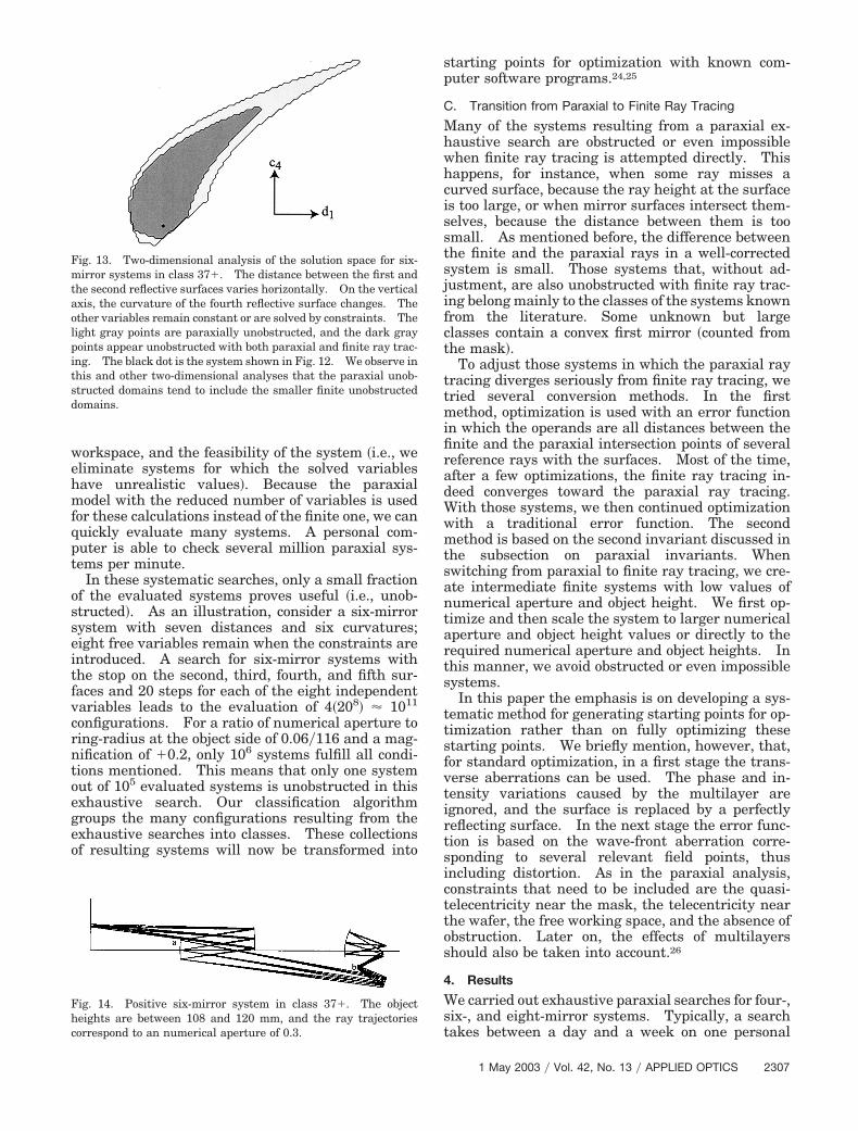
To investigate the differences between paraxialand finite ray tracing, we examine the contours of theobstruction-free domains. Figure 13 gives an exam-ple of a two-dimensional analysis of a system shownin Fig. 14. As in many other cases, we observe thatthe paraxially unobstructed domains tend to includethe smaller finite unobstructed domains.
B. Systematic Paraxial Search
The two-dimensional analysis of the solution spacesshows us the small sizes of the unobstructed do-mains. These domains are bounded by obstruction,and the borders can be found analytically by solutionof systems of equations that take into account allobstruction possibilities. In this paper we opt for amore straightforward systematic paraxial search inwhich all variables vary within realistic ranges. Allthese configurations are tested for obstructions,
Fig. 11. Analytical exploration of the paraxial obstruction bor-ders for the class containing the systems shown in Figs. 12 and 14.A comparison of the paraxial and finite obstruction contours for thesame domain is shown in Fig. 13. The lines in this figure are theobstruction boundaries, found with Eq. �2�. Mirror number 4 ob-structs the beam between mirror numbers 2 and 3 on lines a, b, andd; see point b in Fig. 14. The difference is in the location of theintermediate image: In a the intermediate image is after mirrornumber 4, in b the intermediate image is between mirror numbers2 and 3, and in d the intermediate image is between mirror num-bers 3 and 4. On line c, mirror number 2 borders the beam be-tween the object and the first mirror; see point a in Fig. 14.
Fig. 12. Paraxial rays agree well enough with the finite rays, forthe purpose of a first evaluation of a system that comprises theexamination of, e.g., the presence of obstruction, the workspace,and the telecentricity at the mask and wafer. This exampleshows a six-mirror system in class 37�.
2306 APPLIED OPTICS � Vol. 42, No. 13 � 1 May 2003
workspace, and the feasibility of the system �i.e., weeliminate systems for which the solved variableshave unrealistic values�. Because the paraxialmodel with the reduced number of variables is usedfor these calculations instead of the finite one, we canquickly evaluate many systems. A personal com-puter is able to check several million paraxial sys-tems per minute.
In these systematic searches, only a small fractionof the evaluated systems proves useful �i.e., unob-structed�. As an illustration, consider a six-mirrorsystem with seven distances and six curvatures;eight free variables remain when the constraints areintroduced. A search for six-mirror systems withthe stop on the second, third, fourth, and fifth sur-faces and 20 steps for each of the eight independentvariables leads to the evaluation of 4�208� � 1011
configurations. For a ratio of numerical aperture toring-radius at the object side of 0.06�116 and a mag-nification of �0.2, only 106 systems fulfill all condi-tions mentioned. This means that only one systemout of 105 evaluated systems is unobstructed in thisexhaustive search. Our classification algorithmgroups the many configurations resulting from theexhaustive searches into classes. These collectionsof resulting systems will now be transformed into
starting points for optimization with known com-puter software programs.24,25
C. Transition from Paraxial to Finite Ray Tracing
Many of the systems resulting from a paraxial ex-haustive search are obstructed or even impossiblewhen finite ray tracing is attempted directly. Thishappens, for instance, when some ray misses acurved surface, because the ray height at the surfaceis too large, or when mirror surfaces intersect them-selves, because the distance between them is toosmall. As mentioned before, the difference betweenthe finite and the paraxial rays in a well-correctedsystem is small. Those systems that, without ad-justment, are also unobstructed with finite ray trac-ing belong mainly to the classes of the systems knownfrom the literature. Some unknown but largeclasses contain a convex first mirror �counted fromthe mask�.
To adjust those systems in which the paraxial raytracing diverges seriously from finite ray tracing, wetried several conversion methods. In the firstmethod, optimization is used with an error functionin which the operands are all distances between thefinite and the paraxial intersection points of severalreference rays with the surfaces. Most of the time,after a few optimizations, the finite ray tracing in-deed converges toward the paraxial ray tracing.With those systems, we then continued optimizationwith a traditional error function. The secondmethod is based on the second invariant discussed inthe subsection on paraxial invariants. Whenswitching from paraxial to finite ray tracing, we cre-ate intermediate finite systems with low values ofnumerical aperture and object height. We first op-timize and then scale the system to larger numericalaperture and object height values or directly to therequired numerical aperture and object heights. Inthis manner, we avoid obstructed or even impossiblesystems.
In this paper the emphasis is on developing a sys-tematic method for generating starting points for op-timization rather than on fully optimizing thesestarting points. We briefly mention, however, that,for standard optimization, in a first stage the trans-verse aberrations can be used. The phase and in-tensity variations caused by the multilayer areignored, and the surface is replaced by a perfectlyreflecting surface. In the next stage the error func-tion is based on the wave-front aberration corre-sponding to several relevant field points, thusincluding distortion. As in the paraxial analysis,constraints that need to be included are the quasi-telecentricity near the mask, the telecentricity nearthe wafer, the free working space, and the absence ofobstruction. Later on, the effects of multilayersshould also be taken into account.26
4. Results
We carried out exhaustive paraxial searches for four-,six-, and eight-mirror systems. Typically, a searchtakes between a day and a week on one personal
Fig. 13. Two-dimensional analysis of the solution space for six-mirror systems in class 37�. The distance between the first andthe second reflective surfaces varies horizontally. On the verticalaxis, the curvature of the fourth reflective surface changes. Theother variables remain constant or are solved by constraints. Thelight gray points are paraxially unobstructed, and the dark graypoints appear unobstructed with both paraxial and finite ray trac-ing. The black dot is the system shown in Fig. 12. We observe inthis and other two-dimensional analyses that the paraxial unob-structed domains tend to include the smaller finite unobstructeddomains.
Fig. 14. Positive six-mirror system in class 37�. The objectheights are between 108 and 120 mm, and the ray trajectoriescorrespond to an numerical aperture of 0.3.
1 May 2003 � Vol. 42, No. 13 � APPLIED OPTICS 2307

computer or simultaneously on several personal com-puters. The relative number of systems found with-out obstruction must be controlled. Obtaining toomany systems is cumbersome, but obtaining too fewincreases the risk of overlooking classes. Becausethe total number of systems that can be evaluatedwithin each search is limited, the sampling density ofthe variables decreases when the number of variablesincreases. The searches for four- and six-mirror sys-tems were done with the intended numerical aper-ture. To increase the success probability, we did thesearches for eight-mirror systems with a slightly de-creased numerical aperture.
To keep the evaluation of a system quick, we usedin the search a single field point �corresponding to thecenter of the ring�. The resulting unobstructed do-main of several field points is the intersection of thedomains corresponding to the individual field points.Therefore no useful configurations are lost by use ofonly one field point. The effect of the finite ringwidth �which is equivalent to a small change in objectheight� can also be investigated with Eq. �11�.
Figure 6 shows the different classes found in aparaxial search for four-mirror systems with a posi-tive or negative magnification for NA�h � 0.20�116.The height of the bars corresponds on a logarithmicscale to the volume of the unobstructed domains. Ofthe positive classes, only class 9� leads to usablefinite systems. Lerner et al.18 presented, togetherwith other systems, a four-mirror system named sym-metric design in the 9� class. The four-mirror sys-tems described in a patent publication by Dinger1 fallin classes 2-, 6-, and 10-.
Figure 8 shows the results of exhaustive searchesfor six-mirror systems with positive and negative
magnification for NA�h � 0.30�116. Systems in thesix-mirror classes 26-,3 41�, and 45�16 were encoun-tered in the patent literature. Sometimes unex-pected design possibilities emerge from the paraxialsearches; an example of an exotic design is shown inFig. 15. These designs show the remarkable flexi-bility of the obstruction borders, despite the severelylimited design space. Large incidence angles makesome new unobstructed classes less attractive in thatlarge angles make aberration correction more diffi-cult and the reflectivity of the multilayers smaller.Generally speaking, the searches for four- and six-mirror systems produced no promising new classes.Exceptions are good performing classes in which thesystems start with a convex instead of a concave firstmirror near the mask. Examples are the four-mirror system in class 6- in Fig. 16, the six-mirrorsystem in class 26- in Fig. 17, and the six-mirrorsystem in class 9� in Fig. 15. Relatively large un-obstructed domains, but small free working spaces,are typical for these classes.
Fig. 15. Positive six-mirror system in class 9�. Although theangles of incidence are large, the rms wave-front error can de-crease to ��2 at the chosen values of the numerical aperture �0.3�and the object heights �between 114 and 118 mm�. However, thedistortion is large.
Fig. 16. Four-mirror system in class 6- with a rms wave-fronterror below 0.0266� and distortion below 12 nm. This system hasa wavelength of 13 nm, a numerical aperture of 0.15, and objectheights between 114 and 119 mm.
Fig. 17. This six-mirror system in class 26- resembles the four-mirror class 6- �see Fig. 16� with an additional pair of mirrors in thegroup on the image side. In the four-mirror design, the two mir-rors nearest to the wafer almost cause obstruction. Here theadditional pair of mirrors permits a larger numerical aperture.
Fig. 18. This negative eight-mirror system is an example of sys-tems belonging to class 150-.
2308 APPLIED OPTICS � Vol. 42, No. 13 � 1 May 2003

We found, however, eight-mirror classes promis-ing. Figures 9 and 10 show the different classesfound with negative and positive magnification NA�
h � 0.30�116. An eight-mirror system found inpatent publications27 belongs to the 165� class. Theeight-mirror systems in Fig. 18–22 are representa-tives of new eight-mirror classes. The constructionparameters of these systems can be found in ourpatent.28
5. Conclusion
The absence of obstructions in the beam path of re-flective ring-field projection systems used in EUV li-thography is an essential and a restrictive demand.This requirement leads to severe design limitations,and therefore the parameter space contains onlysmall unobstructed domains.
The dimensionality of searches for starting sys-tems is drastically reduced by use of the paraxialinstead of the finite ray tracing because the asphericsurface coefficients are ignored and the imposed con-straints are used to eliminate variables. This ex-haustive search method permits an efficientidentification of unobstructed domains that can con-tain starting configurations for subsequent optimiza-tion. The analysis technique shows the volume ofthe unobstructed domains. The extensive two-dimensional comparative analyses confirm that ourparaxial search method can be used to detect startingconfigurations in all unobstructed domains of inter-est. The paraxial obstruction-free domains appearto be larger and tend to include the correspondingfinite obstruction-free domains. Therefore it seemsimprobable that interesting domains for startingpoints are not detected by our paraxial obstructionanalysis.
We propose a new classification method based onthe relative arrangement of mirrors in the EUV sys-tem. New possible design forms for EUV imagingsystems belonging to different classes are presented.These examples show that the obstruction borderscan be remarkably flexible, although factors otherthan the absence of obstruction make some of theseclasses less attractive. Other major issues includethe avoidance of large incidence angles, which makeaberration correction difficult and multilayer compat-ibility questionable. Unfortunately, these severe re-
Fig. 19. This negative eight-mirror system is an example of sys-tems belonging to class 182-.
Fig. 20. This positive eight-mirror system is an example of sys-tems belonging to class 169�.
Fig. 21. This positive eight-mirror system is an example of sys-tems belonging to class 173�.
Fig. 22. This positive eight-mirror system is an example of sys-tems belonging to class 181�.
1 May 2003 � Vol. 42, No. 13 � APPLIED OPTICS 2309

strictions make many classes unsuitable for high-quality systems. However, we detected some newclasses that are promising for further development.
The authors thank ASM Lithography for support-ing this research. We gratefully acknowledge theuse on special conditions of the optical design soft-ware program CodeV.
Appendix A
In this appendix we describe the constrained paraxialmodel of a projection system with N reflective sur-faces, magnification m, and numerical aperture NAon the image side. One of the requirements is thatthe aperture stop is accessible. Therefore we con-sider only stop surfaces coinciding with a reflectingsurface �excluding the first and last surfaces�. Sep-arate stop surfaces add only one distance to the num-ber of variables. The chances for obstruction,however, increase drastically. The surface with theaperture stop is indicated with the index S.
Let M be the matrix that relates rays with objectheight h0 and angle u0 with the optical axis in theobject plane to rays in the image plane with heighthN�1 and angle uN�1:
�hN�1
uN�1� � M � �h0
u0� � O�3�, (A1)
where O�3� represents all higher-order terms ne-glected by the paraxial approximation. For a sys-tem with N mirrors, the matrix M can be written as
M � TN � RN � TN�1 � B � A � T1 � R1 � T0. (A2)
The matrices A and B define, respectively, parts ofthe system before and after the surface number swith the aperture stop:
A � �a1 a2
a3 a4� � TS�1 � RS�1 � . . . T2 � R2, (A3)
B � �b1 b2
b3 b4� � RN�1 � TN�2 . . . � TS � RS. (A4)
The transfer matrices Ti and the reflection matricesRi are of the form23
Ti � �1 di
0 1 � , Ri � � 1 0�2ci �1� . (A5)
Note that both the transfer and the reflection matri-ces depend on one single variable, either a distance dito the subsequent surface or a curvature ci of surfacei. Before we impose any constraints, the model con-sists of 2N � 1 variables.
The order of solving variables �i.e., making themdependent on the other variables� with the constraintequalities is important. In this approach, we imposefive constraints on the paraxial model:
1. We adjust one of the curvatures of the surfacesto fulfill the Petzval sum condition �see Eq. �6�. Wechoose to change the surface with the aperture stop
because the curvature cs of this surface does not affectthe principal ray.
2. Subsequently, we solve the distance dN�1 aftersurface N � 1 to obtain a system that is telecentric atthe wafer side. The principal ray propagates fromthe stop surface, where it has the angle us, to the lastmirror according to
RN � TN�1 � B � � 0uS� � �mh0
0 � . (A6)
The distance dN�1 becomes
dN�1 � �b2
b4�
12cN
. (A7)
3 and 4. The object distance d0 and the distanced1 cannot be solved independently, but the two con-ditions of quasi-telecenticity at the mask side and thecorrect magnification of the system lead to two equa-tions with the two distances as unknowns. Theprincipal ray propagates from the object to the sur-face with the aperture stop
A � T1 � R1 � T0 � �h0
u0� � � 0
uS� . (A8)
We want the system to have a magnification m, as aresult of which the principal ray leaves the last mir-ror at a height mh0:
RN � TN�1 � B � A � T1 � R1 � T0 � �h0
u0� � �mh0
0 � . (A9)
Ultimately, the relations of the two distances becomefunctions of known parameters:
d0 � �1
2c1
�
h0��1 �ma1
2��a2 a3 � a1 a4�c1�b2 � b4 d5��
u0,
(A10)
d1 �
mh0�a1 � 2a2 c1� � u0�a2 a3 � a1 a4��b2 � b4 dN�1�
2mh0 a1 c1.
(A11)
The angle u0 of the principal ray in the object spacehas an absolute value close to the numerical apertureof the system on the object side. The number ofparameters of a system decreases and the formulasbecome simpler when the angle of the principal ray u0is chosen equal to the numerical aperture mNA onthe object side.
5. The last requirement is that the surface aftermirror N is the paraxial image plane. Considering amarginal ray propagating through the system, we
2310 APPLIED OPTICS � Vol. 42, No. 13 � 1 May 2003

can solve the distance dN in the last transfer matrixTN from the relation
TN � RN � TN�1 � B � A � T1 � R1 � T0 � � 0mNA� � � 0
NA� .
(A12)
This condition gives the following relation for thedistance dN:
dN � �a2�1 � 2c1 d0��b1 � b3 dN�1� � a4�1 � 2c1 d0��b2
� b4 dN�1� � �d1 � d0��1 � 2c1 d1��a1�b1
� b3 dN�1� � a3�b2 � b4 dN�1����a2�1 � 2c1 d0�
� �b3 � 2b1 cN � 2b3 cN dN�1� � a4�1 � 2c1 d0��b4
� 2b2 cN � 2b4 cN � 2b4 cN dN�1� � �d1 � d0��1
� 2c1 d1��a3 b4 � 2a3 cN�b2 � b4 dN�1�
� a1�b3 � 2b1 cN � 2b3 cN dN�1��. (A13)
References1. U. Dinger, “Ringfeld-4-Spiegelsysteme mit konvexem Primar-
spiegel fur die EUV-Lithography,” European patent EP 0 962830 A1 �8 December 1999�.
2. J. Braat, “Mirror projection system for a scanning lithographicprojection apparatus, and lithographic apparatus comprisingsuch a system,” U.S. patent 6,299,318 �9 October 2001�.
3. J. Braat, “Lithographic apparatus comprising a dedicated mir-ror projection system,” U.S. patent 6,396,067 �28 May 2002�.
4. J. Braat and J. Verhoeven, “Method of imaging a mask patternon a substrate by means of euv radiation, and apparatus andmask for performing the method,” U.S. patent 6,280,906 �28August 2001�.
5. J. Bruning, A. Phillips, D. Shafer, and A. White, “X-ray pro-jection lithography camera,” U.S. patent 5,220,590 �15 June1993�.
6. J. Bruning, A. Phillips, D. Shafer, and A. White, “Lens systemfor X-ray projection lithography camera,” U.S. patent5,353,322 �4 October 1994�.
7. R. Hudyma, “High numerical aperture ring field projectionsystem for extreme ultraviolet lithography,” U.S. patent6,033,079 �7 March 2000�.
8. R. Hudyma, “High numerical aperture ring field projectionsystem for extreme ultraviolet lithography,” U.S. patent6,183,095 �6 February 2001�.
9. R. Hudyma and D. Shafer, “High numerical aperture ring field
projection system for extreme ultraviolet lithography,” U.S.patent 6,188,513 �2 February 2001�.
10. T. Jewell and J. Rodgers, “Apparatus for semiconductor lithog-raphy,” U.S. patent 5,063,586 �5 November 1991�.
11. T. Jewell and K. Tompson, “X-ray ringfield lithography,” U.S.patent 5,315,629 �24 May 1994�.
12. D. Shafer, “Reflective projection system comprising four spher-ical mirrors,” U.S. patent 5,410,434 �25 April 1995�.
13. D. Shafer, “Projection lithography system and method usingall-reflective optical elements,” U.S. patent 5,686,728 �11 No-vember 1997�.
14. M. Suzuki, N. Mochizuki, S. Minami, S. Ogura, Y. Fukuda, Y.Watanabe, Y. Kawai, and T. Kariya, “X-ray reduction projec-tion exposure system of reflection type,” U.S. patent 5,153,898�10 October 1992�.
15. V. Viswanathan and B. Newnam, “Reflective optical imagingsystem for extreme ultraviolet wavelengths,” U.S. patent5,212,588 �18 May 1993�.
16. D. Williamson, “High numerical aperture ring field opticalreduction system,” U.S. patent 5,815,310 �29 September 1998�.
17. D. Williamson, “Four mirror EUV projection optics,” U.S.patent 5,956,192 �21 September 1999�.
18. S. A. Lerner, J. M. Sasian, and M. R. Descour, “Design ap-proach and comparison of projection cameras for EUV lithog-raphy,” Opt. Eng. 39, 792–802 �2000�.
19. J. M. Howard and B. D. Stone, “Imaging a point with twospherical mirrors,” J. Opt. Soc. Am. A 15, 3045–3056 �1998�.
20. J. M. Howard and B. D. Stone, “Imaging a point to a line witha single spherical mirror,” Appl. Opt. 37, 1826–1834 �1998�.
21. J. M. Howard and B. D. Stone, “Imaging with three sphericalmirrors,” Appl. Opt. 39, 3216–3231 �2000�.
22. J. M. Howard and B. D. Stone, “Imaging with four sphericalmirrors,” Appl. Opt. 39, 3232–3242 �2000�.
23. F. Pedrotti and L. Pedrotti, Introduction to Optics �Prentice-Hall, Englewood Cliffs, N.J., 1993�.
24. CODE V, Optical Research Associates, Pasadena, Calif., 2001.25. OSLO, Lambda Research Corporation, Littleton, Mass., 2001.26. M. Bal, F. Bociort, and J. Braat, “Influence of multilayers on
the optical performance of extreme-ultraviolet projection sys-tems,” in International Optical Design Conference 2002, P. K.Manhart and J. M. Sasian, eds., Proc. SPIE 4832, 149–157�2002�.
27. H.-J. Mann, W. Ulrich, and G. Seitz, “8-mirrored microlitho-graphic projector lens,” World Intellectual Property Organiza-tion patent WO 02�33467A1 �25 April 2002�.
28. M. Bal, F. Bociort, and J. Braat, “Lithographic apparatus anddevice manufacturing method,” European patent EP 1 20 9503 A2 �29 May 2002�. �
1 May 2003 � Vol. 42, No. 13 � APPLIED OPTICS 2311
Related Documents