Optica Applicata, Vol. XXXIX, No. 1, 2009 Analysis of the luminous flux diffusion on the optical fiber lateral surface URSZULA BŁASZCZAK, DOMINIK DOROSZ, JAN DOROSZ * , WŁADYSŁAW DYBCZYŃSKI, MACIEJ ZAJKOWSKI Białystok Technical University, Wiejska 45D, 15-351 Białystok, Poland * Corresponding author: [email protected] The method of the analysis of luminous flux diffusion on the lateral surface of an optical fiber as a basis for designing and manufacturing of side-hole optical fibers is presented. The idea of the controllable emission of the luminous flux by formation of the fiber lateral surface is described. The presented method was verified by manufacturing an optical fiber with controllable emission from the shaped lateral surface. Keywords: side-hole optical fiber, luminous flux, diffusion, shaped lateral surface. 1. Diffusion of the luminous flux on the lateral surface of optical fiber The main, widely known, application of an optical fiber is to transfer the optical signal over some distance. In order to achieve this aim, it is necessary, among other things, to reduce energy loss resulting from reflections on the core-cladding border to minimum. In some cases, however, it is recommended to let out the luminous flux through the lateral surface of the optical fiber. The emission of the luminous flux through the lateral surface of the fiber can be realised in many ways [1–4]. One of them assumes the creation of a diffusion layer on the core lateral surface. In this area, some part of the luminous flux from the core penetrates the cladding and then leaves the fiber making its lateral surface shine, whereas the remaining part of the luminous flux gets reflected and stays in the core of this fiber (Fig. 1). The dominant part of the luminous flux reflected back to the core, encompassed by angle 2α kr (smaller than the critical one), reaches the border between the core and the cladding again, and almost completely leaves the fiber through its lateral surface, while the luminous flux encompassed by the range of angles from 90° to (90° – α kr ) spreads in the fiber core in both directions (also backwards).

Welcome message from author
This document is posted to help you gain knowledge. Please leave a comment to let me know what you think about it! Share it to your friends and learn new things together.
Transcript
Optica Applicata, Vol. XXXIX, No. 1, 2009
Analysis of the luminous flux diffusion on the optical fiber lateral surface
URSZULA BŁASZCZAK, DOMINIK DOROSZ, JAN DOROSZ*, WŁADYSŁAW DYBCZYŃSKI, MACIEJ ZAJKOWSKI
Białystok Technical University, Wiejska 45D, 15-351 Białystok, Poland
*Corresponding author: [email protected]
The method of the analysis of luminous flux diffusion on the lateral surface of an optical fiberas a basis for designing and manufacturing of side-hole optical fibers is presented. The idea ofthe controllable emission of the luminous flux by formation of the fiber lateral surface is described.The presented method was verified by manufacturing an optical fiber with controllable emissionfrom the shaped lateral surface.
Keywords: side-hole optical fiber, luminous flux, diffusion, shaped lateral surface.
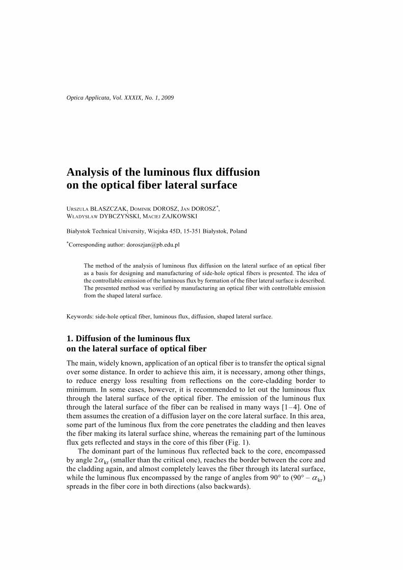
1. Diffusion of the luminous flux on the lateral surface of optical fiberThe main, widely known, application of an optical fiber is to transfer the optical signalover some distance. In order to achieve this aim, it is necessary, among other things,to reduce energy loss resulting from reflections on the core-cladding border tominimum. In some cases, however, it is recommended to let out the luminous fluxthrough the lateral surface of the optical fiber. The emission of the luminous fluxthrough the lateral surface of the fiber can be realised in many ways [1–4]. One ofthem assumes the creation of a diffusion layer on the core lateral surface. In this area,some part of the luminous flux from the core penetrates the cladding and then leavesthe fiber making its lateral surface shine, whereas the remaining part of the luminousflux gets reflected and stays in the core of this fiber (Fig. 1).
The dominant part of the luminous flux reflected back to the core, encompassedby angle 2α kr (smaller than the critical one), reaches the border between the core andthe cladding again, and almost completely leaves the fiber through its lateral surface,while the luminous flux encompassed by the range of angles from 90° to (90° – α kr)spreads in the fiber core in both directions (also backwards).
64 U. BŁASZCZAK et al.
The luminous flux leaving the fiber through its lateral surface depends on the coef-ficient of transmission τ of the cladding and its coefficient of absorption. The coeffi-cient of reflection ρ, on the other hand, will determines the luminous flux reflectedfrom the elementary diffusion surface and directed back to the core.
The analysis of the division of the elementary flux Φp incident on elementarysurface can be carried out by making some simplifying assumptions [3].
1. The ray (vector) represents the elementary luminous flux ΔΦ encompassed bythe elementary solid angle Δω.
2. The optical fiber (with a step-index profile) is rectilinear and its parameters areknown: r – radius of the core, n1 – refractive index of the core, n2 – refractive indexof the cladding.
3. The diffusion layer is flat.4. The elementary surface is characterised by perfect diffusion, both as far as
transmission and reflection are concerned.5. The values of transmission and reflection coefficients of the elementary surface
are known.6. The value of the luminous flux Φp is known.The luminous flux Φw leaving the fiber can be determined from the relation:
Φw = Φp (1)
while the luminous flux Φr directed again into the fiber core
Φr = ρΦp (2)
becomes divided into part Φb leaving the fiber on the side opposite to the elementarysurface (within the area of angle 2αkr) and part Φd, propagated in the core.
Φr = Φb + Φd (3)
In order to determine the values of the luminous fluxes Φb and Φd, the half-spaceadjacent to the elementary surface ΔS should be divided into elementary solid angles
Fig. 1. Local diffusion of the luminous flux onthe border between the core and the cladding.αkr
ΦR
Φw
Analysis of the luminous flux diffusion ... 65
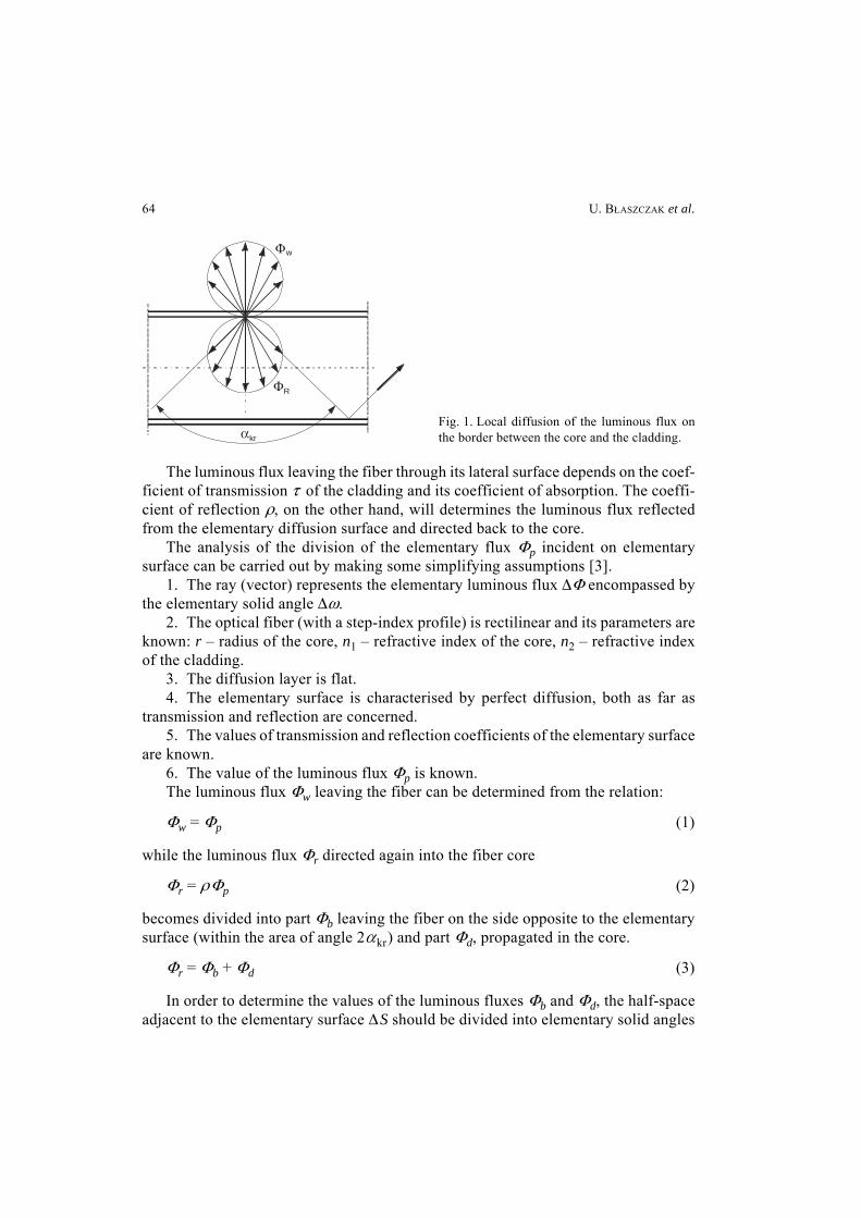
(Fig. 2). For this purpose, a polar coordinate system is adapted with the central pointof the system located in the middle of the discussed elementary area ΔS. This spaceis divided by planes crossing the y-axis of the Cartesian coordinate system withinthe distance of angles Δψ starting from the planes x, y. In each plane ψ a division ofthe space into elementary angles Δϕ is assumed. In chosen plane ψ , the vector P andthe axis y create an angle ϕ. The length of vector P directed to point T on the surfaceof the solid of light distribution equals [3]
|P | = Imcosϕ (4)
while
(5)
The assumed polar coordinate system enables us to dividing the solid of lightdistribution of the reflected flux into bands (variable angle ϕ with ψ = const) andinto zones (variable angle ψ with ϕ = const). In order to divide the half-space intoelementary solid angles with approximate values, different values of elementaryangles Δψ were assumed in particular zones with values approximate to Δϕ = const.The number k of elementary angles Δψ in a given zone was calculated fromthe following relation [3]:
(6)
Thus, the value of the elementary angle Δψ equals 2π /k.
ImΦr
π-----------=
k INT 2π ϕsinΔϕ
----------------------- 1+⎝ ⎠⎜ ⎟⎛ ⎞
=
Fig. 2. Polar coordinate system connected with the solid of light distribution.
x
yImS P
yR
T
P
S
P
z
ϕ
ImΔϕ
ψ
Δψ
x
66 U. BŁASZCZAK et al.
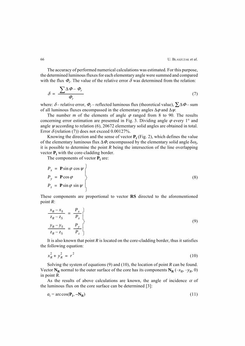
The accuracy of performed numerical calculations was estimated. For this purpose,the determined luminous fluxes for each elementary angle were summed and comparedwith the flux Φr. The value of the relative error δ was determined from the relation:
(7)
where: δ – relative error, Φr – reflected luminous flux (theoretical value), ΣΔΦ – sumof all luminous fluxes encompassed in the elementary angles Δϕ and Δψ.
The number m of the elements of angle ϕ ranged from 8 to 90. The resultsconcerning error estimation are presented in Fig. 3. Dividing angle ϕ every 1° andangle ψ according to relation (6), 20672 elementary solid angles are obtained in total.Error δ (relation (7)) does not exceed 0.00127%.
Knowing the direction and the sense of vector Pi (Fig. 2), which defines the valueof the elementary luminous flux ΔΦ, encompassed by the elementary solid angle δωi,it is possible to determine the point R being the intersection of the line overlappingvector Pi with the core-cladding border.
The components of vector Pi are:
(8)
These components are proportional to vector RS directed to the aforementionedpoint R:
(9)
It is also known that point R is located on the core-cladding border, thus it satisfiesthe following equation:
(10)
Solving the system of equations (9) and (10), the location of point R can be found.Vector NR normal to the outer surface of the core has its components NR (–xR, –yR, 0)in point R.
As the results of above calculations are known, the angle of incidence α ofthe luminous flux on the core surface can be determined [3]:
ai = arccos(Pi , –NR) (11)
δΔΦ Φr–∑
Φr----------------------------------=
Px P ϕsin ψcos=
Py P ϕcos=
Pz P ϕsin ψsin=⎭⎪⎪⎬⎪⎪⎫
xR xS–
zR zS–-----------------------
Px
Pz-----------=
yR yS–
zR zS–-----------------------
Py
Pz-----------=
⎭⎪⎪⎬⎪⎪⎫
xR2 yR
2+ r 2=
Analysis of the luminous flux diffusion ... 67
If angle α i is larger than a certain critical value αkr , the phenomenon of totalinternal reflection occurs and this elementary luminous flux is joined and propagatedin the fiber core Φd . Angle αkr depends on the refractivity of the core and cladding:
(12)
If the angle of incidence α i of the elementary luminous flux is smaller thanthe critical value αkr , the phenomenon of Fresnel reflection takes place and onlya small part of the flux is reflected (ρf ), while its substantial part goes to the cladding.The Fresnel reflection coefficient can be determined from the relation:
(13)
where is the angle of refraction.
The luminous flux, which goes to the cladding, is added to the sum Φb, because itleaves the fiber through the lateral surface.
A part of the luminous flux reflected from the core lateral surface is proportionalto the reflection coefficient ρ f . It reaches the core lateral surface which is againopposite to the point S. The angle of incidence is also equal to α i, thus its dominantpart goes to the cladding, though the phenomenon of Fresnel reflection appears hereas well. This phenomenon occurs many times and the luminous flux is constantlyweakened.
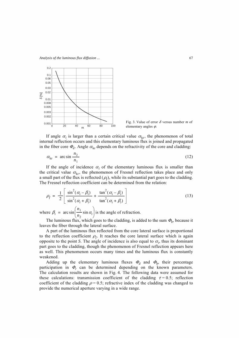
Adding up the elementary luminous fluxes Φd and Φb, their percentageparticipation in Φr can be determined depending on the known parameters.The calculation results are shown in Fig. 4. The following data were assumed forthese calculations: transmission coefficient of the cladding τ = 0.5; reflectioncoefficient of the cladding ρ = 0.5; refractive index of the cladding was changed toprovide the numerical aperture varying in a wide range.
αkr arcn2
n1----------sin=
ρf12
-------sin2 αi βi–( )
sin2 αi βi+( )------------------------------------
tan2 αi βi–( )
tan2 αi βi+( )------------------------------------+=
βi arcn1
n2-------- αisin⎝ ⎠⎜ ⎟⎛ ⎞
sin=
Fig. 3. Value of error δ versus number m ofelementary angles ϕ.0 20 40 60 80m
0.001
0.0020.003
0.0050.0080.01
0.020.03
0.050.08
0.1
0.2
δ [%
]
100
68 U. BŁASZCZAK et al.
The analysis presented above proves that irrespectively of the direction of the rayincidence on the cladding surface, the luminous flux in the core is propagating alongthe fiber in both directions.
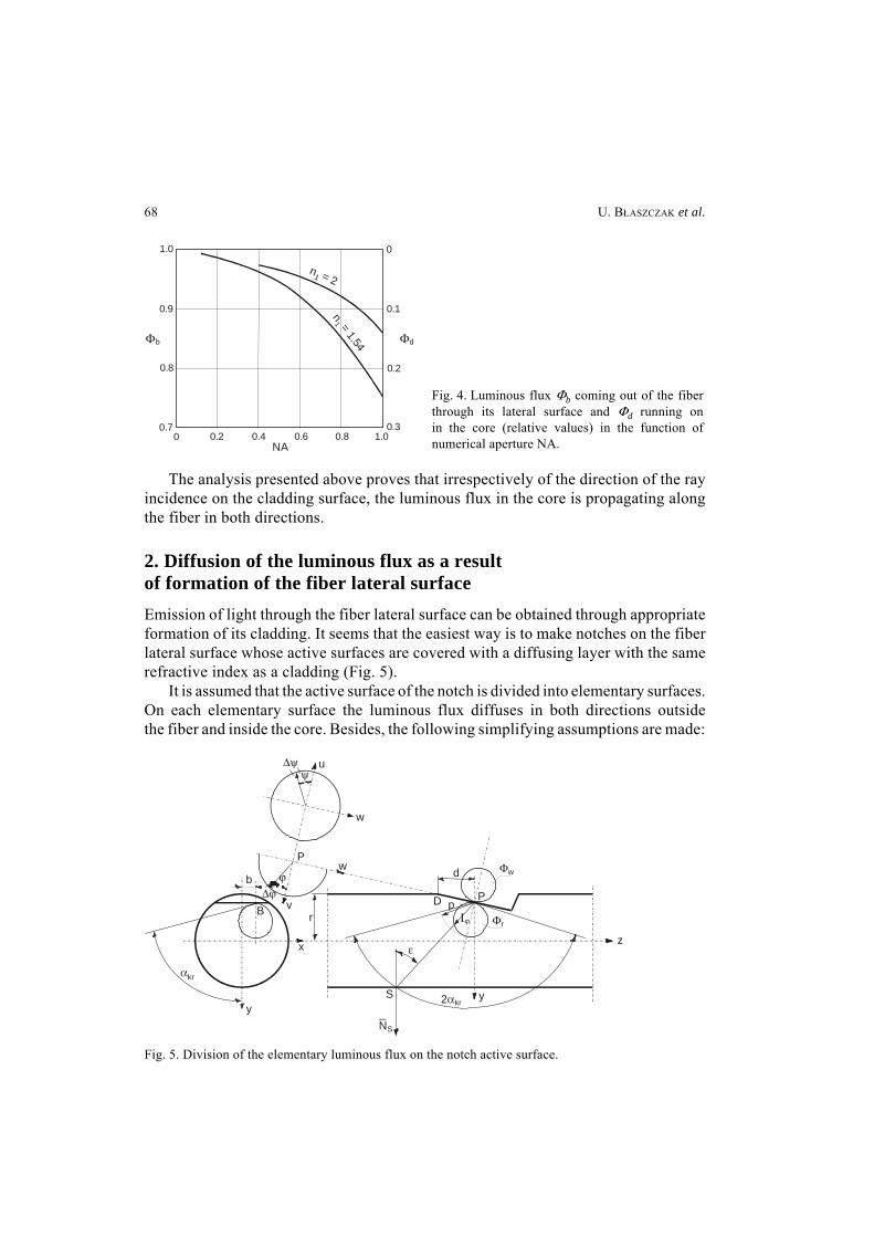
2. Diffusion of the luminous flux as a result of formation of the fiber lateral surfaceEmission of light through the fiber lateral surface can be obtained through appropriateformation of its cladding. It seems that the easiest way is to make notches on the fiberlateral surface whose active surfaces are covered with a diffusing layer with the samerefractive index as a cladding (Fig. 5).
It is assumed that the active surface of the notch is divided into elementary surfaces.On each elementary surface the luminous flux diffuses in both directions outsidethe fiber and inside the core. Besides, the following simplifying assumptions are made:
Fig. 4. Luminous flux Φb coming out of the fiberthrough its lateral surface and Φd running onin the core (relative values) in the function ofnumerical aperture NA.0 0.2 0.4 0.6 0.8 1.0
NA
0.7
0.8
0.9
1.0 0
0.1
0.2
0.3
Φb Φd
n = 21
n = 1.54
1
Fig. 5. Division of the elementary luminous flux on the notch active surface.
v
w
u
w
r
P
b
y
x
S
NS
z
d
D pP
y
B
Δψψ
Δϕϕ
αkr
Φw
ΦrΙϕ
2αkr
ε
Analysis of the luminous flux diffusion ... 69
1. The ray of light represented by a vector is a carrier of the elementary luminousflux ΔΦ encompassed by the elementary solid angle Δω.
2. The following parameters of the optical fiber are known (Fig. 5): γ – angle ofinclination of the notch, r – radius of the core, d – distance from the analysed point tothe beginning of the notch (along the z-axis), b – distance from the analysed pointto the axis of symmetry (along the x-axis); the cladding thickness is insignificantlysmall.
3. The elementary surface of the notch is characterised by even diffusion, bothduring transmission and reflection of the luminous flux.
4. Values of the following coefficients are known: transmission τ and reflection ρof the notch active surface.
The luminous flux Φp incidents the elementary surface, in the middle of whichthe analysed point is located (Fig. 5), and becomes divided into three parts: Φr – partof the luminous flux directed back to the core, Φw – the luminous flux going outsideand Φα – the flux absorbed by the diffusing layer:
Φp = Φr + Φw + Φα = ρΦp + τΦp + αPΦp (14)
where αP – absorption coefficient of the cladding.The luminous flux directed back into the core Φr in its considerable part (Φb ) leaves
the fiber through the surface at the place located opposite the notch. When the angleof the luminous beam incidence, however, is larger than the critical angle, the phenom-enon of total internal reflection occurs. Then, this small part of the luminous fluxpropagates along the fiber in both directions. The luminous flux running in accordancewith the direction of propagation (the z-axis) is marked Φd, and the one running inthe opposite direction – Φu.
Thus, the reflected luminous flux Φr gets divided into three parts
Φr = Φb + Φd + Φu (15)
In order to determine the percentage participation of the flux in each part, a polarsystem of coordinates p, ϕ, ψ is adapted with its centre located in the analysedpoint P. This point is situated on the notch active surface. In the Cartesian system itscoordinates are (b, r – a, 0). The polar coordinate system is rotated at angle γ aroundthe axis parallel to the x-axis and crossing it in point P. Angle ϕ is measured fromthe v-axis, perpendicular to the notch active surface, whereas angle ψ is located inthe plane of the notch surface.
A randomly chosen point T, located within the distance p from point P, is describedby the following coordinates [3, 5]:
(16)
vT p ϕcos=
uT p ϕ ψcossin=
wT p ϕ ψsinsin= ⎭⎪⎬⎪⎫
70 U. BŁASZCZAK et al.
In the Cartesian coordinate system x, y, z this point is described by the relations:
(17)
Determination of the angle of incidence ε of the ray overlapping the direction oflight intensity Iϕ,ψ on the core lateral surface is a significant part of the analysis.The light intensity and the value of the elementary solid angle Δωϕψ are a measure ofthe elementary luminous flux. By comparing the angle of incidence ε with the valueof the critical angle, the considered luminous flux can be rated to a proper part ofthe flux, according to relation 15. When angle ε is larger than the critical one, thenthe location of point S on the core surface determines the further division of this flux.Thus, if zS < 0, the elementary luminous flux propagates in the opposite direction (Φu ),and when zS > 0, it runs according to the direction of propagation (Φd ).
In the calculations, the even division of angle ϕ into m-element zones is assumed,whereas angle ψ is divided equally in each zone to obtain approximately equalelementary solid angles Δωϕψ . Thus, the number n of elementary angles ψ for eachzone is determined from the relation:
(18)
where: Δψ = 90°/m, i – number of the zone.Point S, located at the intersection of the straight line going through points P and
T with the core side surface, can be determined from the following system of equations:
(19)
The solution of this system of equations, after applying the substitution method, isthe quadratic equation (7) in the form:
(20)
xT p ϕ ψcoscos b+=
yT p ϕcos γcos p ϕsin ψ γsinsin r– a+ +=
zT p ϕ ψ γcossinsin p ϕcos γsin–= ⎭⎪⎬⎪⎫
ni INT 2π ϕsinΔϕ
----------------------- 1+⎝ ⎠⎜ ⎟⎛ ⎞
=
x xP–
xT xP–-----------------------
y yP–
yT yP–-----------------------
z zP–
zT zP–----------------------- equation of the line= =
x2 y2+ r2 equation of the cylindrical surface= ⎭⎪⎬⎪⎫
xT b–( )2
yT r a–+------------------------------ 1+ yS
2 2xT b–( )2 r a–( )
yT r a–+( )2--------------------------------------------
b xT b–( )yT r a–+
-----------------------------+ yS
xT b–( )2 r a–( )2
yT r a–+( )2---------------------------------------------- 2
b xT b–( ) r a–( )yT r a–+
--------------------------------------------- b2 r2–
+ +
+ + + 0=
Analysis of the luminous flux diffusion ... 71
Getting the coordinate yS of point S from the system of equations (19), the coordi-nates xS and zS can be determined.
The normal unit vector has its components NS (xS /r, yS /r, 0) in point S, thus angleε can be calculated from the relation:
(21)
whereas vector SP has the components:
SP(xS – xP ; yS – yP ; zS – zP) = SP(xS – b; yS +r – a ; zS)
If the following inequality is satisfied
(22)
where: n1 – refractive index of the core material, n2 – refractive index of the claddingmaterial; the elementary luminous flux runs from the core to the cladding. In this caseangle ε is smaller than the critical one. The luminous flux formed due to Fresnelphenomenon incidents the lateral surface of the core again at the same angle ε andits dominant part goes to the cladding as well. Therefore, this phenomenon was notanalysed as it influences only the direction of the outlet of the luminous flux and hasno impact on its value.
If the following inequality is satisfied
(23)
the phenomenon of total internal reflection occurs on the border between the core andthe cladding and the luminous flux becomes divided and propagates along the core inboth directions. This division does not have to be equal.
The following values are assumed for the calculations:– number of zones in angle ϕ is m = 91,– number of elements of angle ψ is n = 4–360,– radius of the core r equal to 5 arbitrary units,– angle of the notch inclination γ = 0°–40°,– distance from the discussed point to the beginning of the notch d = 0–10 units,– distance from the discussed point to the axis of symmetry b = 0–4.5 units,– refractive index of the core n1 = 1.54,– refractive index of the cladding n2 = 1.399–1.530,– numerical aperture of the fiber is selected in order to get the following acceptance
angles α = 10°, 20°, 30° and 40°.
εcosNS SP⋅
SP-----------------------⎝ ⎠⎜ ⎟⎛ ⎞
cos=
n1
n2---------- εsin 1<
n1
n2---------- εsin 1>
72 U. BŁASZCZAK et al.
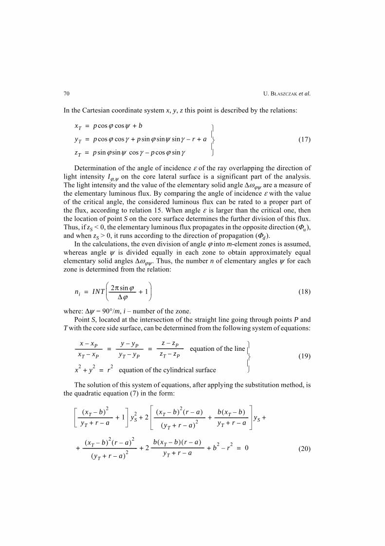
Figure 6 presents the calculated percentage value of the luminous flux Φb, leavingthe fiber through the lateral surface in relation to the flux Φr reflected from the core--cladding border versus the angle γ of the notch inclination for chosen values ofthe acceptance angle α .
Figure 7 presents the courses of relative values of the luminous fluxes Φd and Φu(in relation to the flux Φr) propagating in the core: according to the sense of the z-axis
0 10 20
20°
30
30°
40
40°
80
100
90
95
85
αgr = 10°
Φb [
%]
γ [deg] 0 10
10°
20
20°20°
30
30°
30°
40
40°
40°
0
10
6
8
2
4
γ [deg]
ΦΦ
du
, [%
]
αgr = 10°
Fig. 6. Relative value of the luminous flux Φb leaving the fiber through its lateral surface versus the angleγ of the notch inclination.
Fig. 7. Relative values of the luminous fluxes Φd and Φu in the function of angle γ of the notch inclination:Φd – continuous lines; Φu – dashed lines.
0 2 4
20°
6
30°
10
αgr = 10°
40°
70
100
85
75
80
8d
95
90
Φb
[%]
10°20°
30°
40°
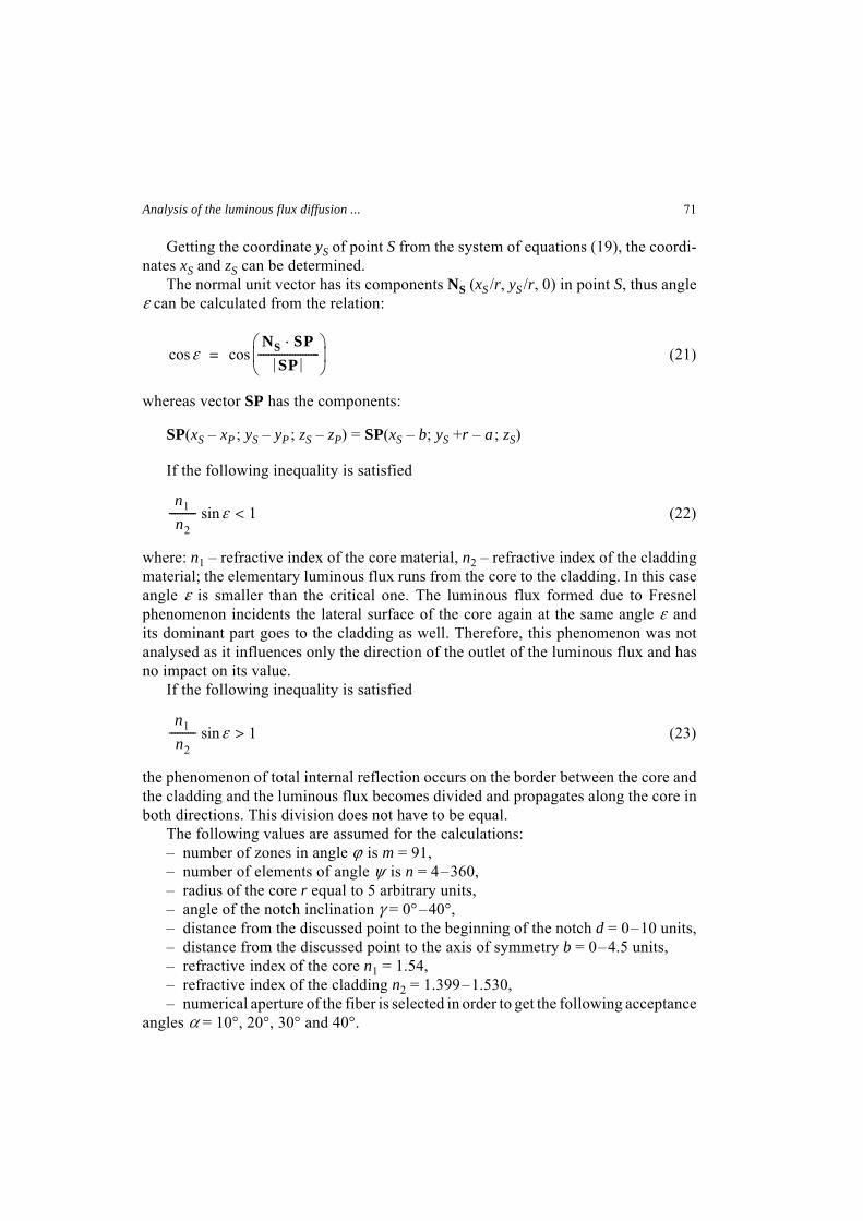
Fig. 8. Relative value of the luminous flux Φbleaving the fiber through the lateral surface versusthe distance d for four values of the acceptanceangle α : γ = 10° – continuous lines; γ = 30° – dashedlines.
Analysis of the luminous flux diffusion ... 73
and in the opposite direction, respectively, versus the angle γ of the notch inclinationfor four values of the fiber acceptance angle.
The values of the luminous fluxes (Φb, Φd and Φu) depend on the position ofthe analysed point P on the notch active surface as well. The course of changes inthe relative value of the luminous flux Φb leaving the fiber through its lateral surfaceversus the distance d between the position of the analysed point and the point P along
0 2 4 6 100
6
2
4
8
8
Φd [
%]
d
10° 20°
30°
40°
40°
30°αgr = 10°
20°
0 2 4 6 100
15
5
10
8
20
Φu [
%]
d
40°
30°
20°10°
40°
30°20°αgr = 10°
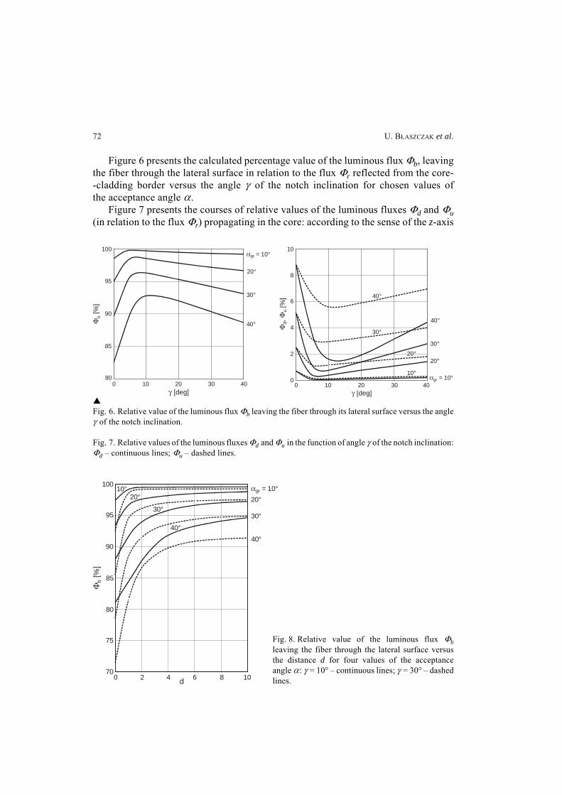
Fig. 9. Relative value of the luminous flux Φd propagating in the fiber core in the direction compatiblewith the sense of the z-axis versus the distance d for four values of the fiber acceptance angle α :γ = 10° – continuous lines; γ = 30° – dashed lines.
Fig. 10. Relative value of the luminous flux Φu propagating in the fiber core in the direction oppositeto the sense of the z-axis versus the distance d for four values of the fiber acceptance angle α :γ = 10° – continuous lines; γ = 30° – dashed lines.
Fig. 11. Relative values of the luminous flux Φbleaving the fiber through the lateral surfaceversus the distance b from the position ofthe analysed point P for four values of the fiberacceptance angle α : γ = 10° – continuouslines; γ = 30° – dashed lines.0 1 2 3 5
50
60
4
100
80
90
70
Φb [
%]
b
40°
30°
20°
10°
20°
30°
40°
αgr = 10°
74 U. BŁASZCZAK et al.
the z-axis (point D in Fig. 5), for four values of the fiber acceptance angle α and twovalues of angle γ of the notch inclination is presented in Fig. 8. Figures 9 and 10 showthe courses of relative values of the luminous fluxes (Φd and Φu) versus the distanced for four values of angle α and two values of angle γ.
The influence of the position of point P in the transverse direction (along the x-axis)on the values of the analysed luminous fluxes was examined. The course of the changes(in relative values) of the luminous flux Φb leaving the fiber through the lateral surfaceversus the distance b determines the position of the analysed point to the axis ofsymmetry towards the x-axis (point B in Fig. 5), for four values of the fiber acceptanceangle α and two values of angle γ of the notch inclination is presented in Fig. 11.
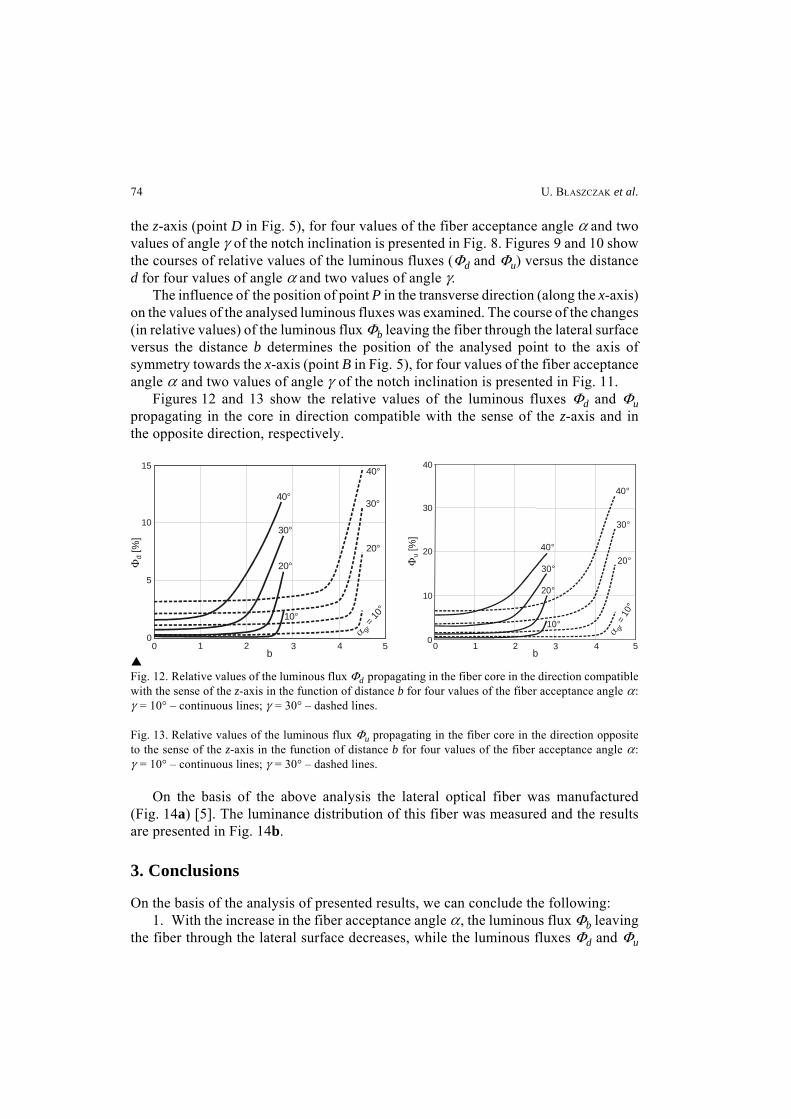
Figures 12 and 13 show the relative values of the luminous fluxes Φd and Φupropagating in the core in direction compatible with the sense of the z-axis and inthe opposite direction, respectively.
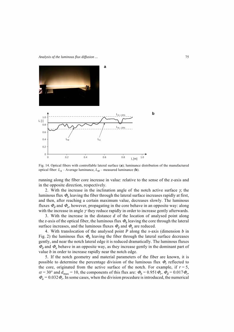
On the basis of the above analysis the lateral optical fiber was manufactured(Fig. 14a) [5]. The luminance distribution of this fiber was measured and the resultsare presented in Fig. 14b.
3. Conclusions
On the basis of the analysis of presented results, we can conclude the following:1. With the increase in the fiber acceptance angle α , the luminous flux Φb leaving
the fiber through the lateral surface decreases, while the luminous fluxes Φd and Φu
0 1 2 3 50
5
4
10
15
Φd [
%]
b
40°
30°
20°
10°
30°
20°
α gr =
10°
40°
0 1 2 3 50
10
4
20
30
40
Φu [
%]
b
40°
30°
20°
10°
30°
20°
40°
α gr =
10°
Fig. 12. Relative values of the luminous flux Φd propagating in the fiber core in the direction compatiblewith the sense of the z-axis in the function of distance b for four values of the fiber acceptance angle α :γ = 10° – continuous lines; γ = 30° – dashed lines.
Fig. 13. Relative values of the luminous flux Φu propagating in the fiber core in the direction oppositeto the sense of the z-axis in the function of distance b for four values of the fiber acceptance angle α :γ = 10° – continuous lines; γ = 30° – dashed lines.
Analysis of the luminous flux diffusion ... 75
running along the fiber core increase in value: relative to the sense of the z-axis andin the opposite direction, respectively.
2. With the increase in the inclination angle of the notch active surface γ, theluminous flux Φb leaving the fiber through the lateral surface increases rapidly at first,and then, after reaching a certain maximum value, decreases slowly. The luminousfluxes Φd and Φu, however, propagating in the core behave in an opposite way: alongwith the increase in angle γ they reduce rapidly in order to increase gently afterwards.
3. With the increase in the distance d of the location of analysed point alongthe z-axis of the optical fiber, the luminous flux Φb leaving the core through the lateralsurface increases, and the luminous fluxes Φd and Φu are reduced.
4. With translocation of the analysed point P along the x-axis (dimension b inFig. 2) the luminous flux Φb leaving the fiber through the lateral surface decreasesgently, and near the notch lateral edge it is reduced dramatically. The luminous fluxesΦd and Φu behave in an opposite way, as they increase gently in the dominant part ofvalue b in order to increase rapidly near the notch edge.
5. If the notch geometry and material parameters of the fiber are known, it ispossible to determine the percentage division of the luminous flux Φr reflected tothe core, originated from the active surface of the notch. For example, if r = 5,α = 30° and dmax = 10, the components of this flux are: Φb = 0.951Φr, Φd = 0.017Φr,Φu = 0.032Φr. In some cases, when the division procedure is introduced, the numerical
0
0.2
0.4
0.6
0.8
1.0
0 0.2 0.4 0.6 0.8 1.0
L [-]
l [m]r
LM LA
LA + 20%
LA – 20%
Fig. 14. Optical fibers with controllable lateral surface (a); luminance distribution of the manufacturedoptical fiber: LA – Average luminance, LM – measured luminance (b).
a
b
76 U. BŁASZCZAK et al.
analysis is simplified without generating any major errors. This can be useful inthe process of designing an optical fiber, which emits radiation through the lateralsurface.
Acknowledgments – The work was supported by Polish Ministry of Science and Higher Education,Research Project No. 3T08D 046 29.
References[1] PENG LEE, Shaped optical fiber light and manufacturing method thereof, United States Patent
No.7258476.[2] ZAJKOWSKI M., The analysis of light flux distribution from shaping optical fiber, Proceedings of
SPIE 6347, 2006.[3] DOROSZ J., DYBCZYŃSKI W., Analysis of luminous flux transfer trough a conical ring-core light
guide, Optica Applicata 34 (3), 2004, pp. 349–364.[4] PUSTELNY T., BARCZAK K., GUT K., WOJCIK J., Special optical fiber type D applied in optical sensor
of electric currents, Optica Applicata 34 (4), 2004, pp. 531–539.[5] DOROSZ D., ZAJKOWSKI M., Optical properties of glasses for sight light emission waveguides,
Proceedings of XXI International Congress on Glass, Strasbourg, France 2007.
Received May 2, 2008
Related Documents


![INNOVA · 2020. 2. 11. · CZECH LIGHT FITTINGS 13 INNOVA PC INNOVA PC Type Max. ambient temperature [°C] Luminous flux of LED modules [lm] Luminous flux of light fitting [lm] Power](https://static.cupdf.com/doc/110x72/60c5d8f5bc339b34584104f5/innova-2020-2-11-czech-light-fittings-13-innova-pc-innova-pc-type-max-ambient.jpg)