1 Analysis of the Instability Phenomena Caused by Steam in High-pressure Turbines Paolo Pennacchi* Politecnico di Milano, Department of Mechanical Engineering, Via La Masa 1, 20156 Milan, Italy. Andrea Vania Politecnico di Milano, Department of Mechanical Engineering, Via La Masa 1, 20156 Milan, Italy. Abstract: Instability phenomena in steam turbines may happen as a consequence of certain characteristics of the steam flow as well as of the mechanical and geometrical properties of the seals. This phenomenon can be modeled and the raise of the steam flow and pressure causes the increase of the cross coupled coefficients used to model the seal stiffness. As a consequence, the eigenvalues and eigenmodes of the mathematical model of the machine change. The real part of the eigenvalue associated with the first flexural normal mode of the turbine shaft may become positive causing the conditions for unstable vibrations. The original contribution of the paper is the application of a model-based analysis of the dynamic behavior of a large power unit, affected by steam-whirl instability phenomena. The model proposed by the authors allows studying successfully the experimental case. The threshold level of the steam flow that causes instability conditions is analyzed and used to define the stability margin of the power unit. Keywords: rotordynamics, steam-whirl, steam-whip, instability, model based analysis (*) Corresponding author: tel. +39-02-2399.8440, fax +39-02-2399.8492, [email protected]

Welcome message from author
This document is posted to help you gain knowledge. Please leave a comment to let me know what you think about it! Share it to your friends and learn new things together.
Transcript
1
Analysis of the Instability Phenomena Caused by Steam in High-pressure Turbines Paolo Pennacchi* Politecnico di Milano, Department of Mechanical Engineering, Via La Masa 1, 20156 Milan, Italy. Andrea Vania Politecnico di Milano, Department of Mechanical Engineering, Via La Masa 1, 20156 Milan, Italy. Abstract: Instability phenomena in steam turbines may happen as a consequence of certain
characteristics of the steam flow as well as of the mechanical and geometrical properties of the seals. This phenomenon can be modeled and the raise of the steam flow and pressure causes the increase of the cross coupled coefficients used to model the seal stiffness. As a consequence, the eigenvalues and eigenmodes of the mathematical model of the machine change. The real part of the eigenvalue associated with the first flexural normal mode of the turbine shaft may become positive causing the conditions for unstable vibrations. The original contribution of the paper is the application of a model-based analysis of the dynamic behavior of a large power unit, affected by steam-whirl instability phenomena. The model proposed by the authors allows studying successfully the experimental case. The threshold level of the steam flow that causes instability conditions is analyzed and used to define the stability margin of the power unit.
Keywords: rotordynamics, steam-whirl, steam-whip, instability, model based analysis
(*) Corresponding author: tel. +39-02-2399.8440, fax +39-02-2399.8492, [email protected]
2
1 Introduction
Steam-whirl instability phenomena in rotating machines can cause a very quick growth of the
amplitude of the shaft vibrations that can reach high levels in a very short time. In general, the
occurrence of subsynchronous vibrations is a typical symptom of this malfunction. Contrary to
oil-whirl subsynchronous vibrations due to fluid-film destabilizing forces in journal bearings
[1][2][3], the frequency of the subsynchronous vibrations caused by steam-whirl phenomena can
be rather different from half of the shaft rotating frequency. Sometimes the frequency of these
subsynchronous vibrations is rather close to the damped natural frequency associated with the
first flexural normal mode of the turbine shaft evaluated at the operating speed [4]. With regard to
this, it is important to consider that steam-whirl instability onsets generally occur in on-load
operating conditions characterized by high values of steam pressure and flow [5][6][7].
Moreover, the machine running speed can be significantly higher than the first flexural critical
speed of the steam turbine shafts that are included in the machine-train. Therefore, the
synchronization between the frequency of the subsynchronous destabilizing forces generated by
the seals and the frequency associated with a flexural critical speed, commonly the first one, is
not unusual. In this case, the large energy flow introduced into the rotor system by the
destabilizing forces can cause very high levels of subsynchronous vibrations of the shaft.
Depending on the sign of the modal damping factor associated with the first flexural critical
speed, vibrations with expanding amplitude may happen. In this case, even if this term is not used
in literature, the phenomenon should be more precisely defined as steam-whip instability.
In general, the dynamic stiffness of the seals are modeled by means of linearized coefficients
that are significantly influenced by the seal geometrical characteristics [5]. Further parameters
that provide important contributions to the value of the seal stiffness coefficients in steam
turbines are the steam pressure and flow. The main destabilizing effects are the unsymmetrical
circumferential pressure distribution and the unbalanced torque forces due to the varying radial
clearance of the seals [8][9]. Therefore, the actual available radial clearance, which depend on the
eccentricity ratio of the shaft, plays a basic role in the magnitude and frequency of the
destabilizing forces generated by the seals [10][11][12][13].
In general, the main dynamic effects of the seals in steam turbines can be modeled by means
of cross-coupled coefficients that have the same magnitude and opposite sign [5][13][14]. The
raise of the steam pressure and flow, which is basically related to a raise of the megawatt load,
often causes a considerable increasing of the cross-coupled stiffness coefficients of the seals
[15][16][17]. Therefore, at high power levels, the considerable increase of the seal stiffness
coefficients can cause important changes in some modal damping factors associated with the
flexural critical speeds of the machine-train as well as in the shape of the respective normal
3
modes of the shafts. Depending on the sign of the modal damping factors, the condition for the
generation of unstable vibrations can occur.
This phenomenon can be investigated by means of the analysis of the eigenvalues of the
rotating machine model performed at the operating speed [18][19]. Different case studies must be
carried out considering the seal stiffness coefficients associated with different values of the steam
flow. The results of this analysis allow the changes of the flexural critical speeds and the
respective modal damping factors, due to the seal stiffening, to be investigated. Sometimes the
progressive growth of the seal stiffness coefficients causes the values of two or more flexural
critical speeds of the shaft-train to converge.
The paper proposes the analysis of the progressive changes of the real and imaginary parts of
the system eigenvalues as well as the analysis of the changes in the shape of the eigenmodes of
the shaft-train. This provides very interesting information that can be used to optimize the
machine design and to adjust some process parameters of the plant that can allow the rotating
machine to be temporarily operated in safety condition by reducing the seal stiffness magnitude
or by causing suitable changes of the dynamic stiffness of the oil-film journal bearings. The same
analysis proposed here allows the threshold level of steam flow, or load, that causes steam-whirl
instability phenomena to be evaluated. On the basis of these results, the stability margin of the
power unit can be easily determined as the amount of extra steam flow, in comparison to the
nominal rating, needed to cause unstable vibrations.
A more accurate evaluation of the stability margin can be obtained by applying perturbation
techniques in actual operating conditions of the rotating machine [20][21]. Since this strategy is
based on experimental tests, it takes into account the actual non-linear effects in the machine
response whose importance may become considerable when high vibration levels due to
instability phenomena occur.
This paper shows also the results of the model-based analysis of the dynamic behavior of a
large power unit affected by steam-whirl instability phenomena. The changes in the real and
imaginary parts of the system eigenvalues, along with the changes in the shape of the respective
eigenmodes of the shaft-train caused by the increase of the seal stiffness, have been studied by
means of parametric analyses. This allowed the dependence of the seal stiffness on the steam
flow and the effects of shaft-to-seal misalignments on the machine vibrations to be investigated.
The stability margin of the power unit has been evaluated for both aligned and misaligned seals
of the high pressure (HP) steam turbine. The results of these studies have been compared with
experimental findings.
Moreover, the effects of suitable changes of the flexural stiffness of the HP turbine shaft on
the stability margin of the unit have been investigated, in order to prevent the occurrence of
steam-whirl instability phenomena even in the case of partial misalignments of the seals as well
4
as in the case of an underestimation of the actual values of the cross-coupled stiffness
coefficients.
2 Definition of the instability factor and of the analysis criteria
The fully assembled rotating machine considered here is composed of a shaft-train, journal
bearings and a foundation structure. The dynamic behavior of the system can be studied using
model-based techniques [22]. A finite element model (FEM) is often used to describe the
mechanical properties of the shaft-train, while the dynamic effects caused by seals, fluid-film
journal bearings and rolling bearings can be modeled by means of dynamic stiffness coefficients
that may depend on the shaft rotating speed. In the end, machine casings, supports and foundation
structure can be modeled by means of well known different techniques [22][23][24][25] here not
described in detail for the sake of brevity.
The free motion equation of a rotating machine can be expressed as:
[ ] [ ] [ ]( ) [ ] 0+ + + =M x C G x K x (1)
where x is the vector that contains the translational and angular displacements associated with the
degrees of freedoms (d.o.f.s) of shafts and foundation.
The mass, stiffness and damping matrices [ ]M , [ ]K and [ ]C describe the dynamic effects of
the whole rotating machine while the matrix [ ]G takes into account the gyroscopic effects of the
shaft-train.
The dynamic effects caused in steam turbines by the stiffness of the seals can be modeled by
means of a pair of cross-coupled coefficients, having the same magnitude and opposite sign, that
are assembled in the off-diagonal locations of the stiffness matrix [ ]s jK associated with the j-th
seal. In a fixed frame coordinate system xy this matrix can be written as:
[ ]0
0xy
s jyx
kk
=
K (2)
where xy yxk k= − [5][13][14]. These stiffness coefficients, which are assembled in suitable
locations of the global stiffness matrix [ ]K , depend on various factors like the seal geometry, the
steam pressure and flow [19]. Moreover, pre-swirling and injection can significantly affect the
seal stiffness coefficients.
In power units, whose machine-train contains steam turbines, the raise of megawatt load and
steam flow can causes a significant hardening of the cross-coupled stiffness coefficients of the
seals defined by eq. (2). They can be responsible for self-excited rotor instability phenomena
characterized by a subsynchronous shaft whirl that is generally associated with the first flexural
5
normal mode of the rotor. The analysis of the eigenvalues of the rotating machine model can be
used to point out the conditions that must be satisfied for the occurrence of unstable vibrations.
The k-th complex eigenvalue of the model can be written as:
i 2k k dkfλ σ π= − + (3)
where dkf is the k-th damped natural frequency of the system while kσ is the respective
modal damping factor. In order to cause energy dissipation the factor kσ must be positive.
The respective undamped natural frequency is given by:
( )2 21 22nk dk kf fπ σπ
= + (4)
The k-th dimensionless damping factor, hk, can be expressed in the following form:
( )2k k dkh fσ π= (5)
In order to have oscillating motions the dimensionless damping factor must be positive and
lower than unity. Under the assumption that the rotor system vibrates in the free motion with an
harmonic law having a frequency equal to the k-th damped natural frequency dkf , the time
history of the displacements evaluated at the j-th d.o.f. xj can be written as:
( ) cos( 2 )j j dk jtkx t X e f tσ π ϕ−= + (6)
Let us denote Tk the time period associated with the frequency dkf . The corresponding
instability factor Vk can be expressed by the ratio between the vibration amplitudes evaluated at
the two instants t1 and t2 that satisfy the following relationship: 2 1 kt t T+= . Then, the logarithm
of the instability factor is given by:
2ln ( ) 2 1k k kV h hπ= − − (7)
When the instability factor Vk exceeds unity, the rotating machine can be affected by
instability phenomena. In general, the destabilizing forces due to the oil-film forces in journal
bearings cause subsynchronous vibrations of the shaft whose frequency is very close to half the
rotating frequency (0.5X) [1][2][3]. In contrast, the whirling phenomena due to the effects of
seals mainly cause subsynchronous vibrations whose harmonic order depends on the geometrical
properties of the seals as well as on some basic characteristics of the fluid flow. The fluid average
circumferential velocity ratio plays a basic role in determining the order of the subsynchronous
vibrations [10]. When the frequency of these vibrations is close to the first flexural critical speed
of the turbine shaft, the risk of the occurrence of serious steam-whip instability phenomena
becomes more critical. Owing to the characteristics of the instability phenomena, the amplitude
of the subsynchronous vibrations can grow very quickly causing severe and catastrophic damages
if an automatic machine trip is not timely activated by a suitable protection system. When the
6
machine operating conditions cause the instability factor to approach its respective threshold
level, the non-linear effects in the dynamic behavior of the system may become considerable.
Therefore, a non-linear model of the machine-train should be used to perform a more accurate
analysis of steam-whip instability phenomena [26].
Let us denote *xyik the stiffness coefficient of the i-th seal evaluated considering the rated
load. Accurate estimates of the seal stiffness coefficients associated with specific operating
conditions can be obtained by means of suitable simulation models or CFD calculations [17],
however, within a preliminary study of the dynamic behavior of a steam-turbine power unit,
approximated estimates of these parameters can be obtained by multiplying the nominal value of
the seal stiffness coefficients *xyik by the dimensionless megawatt load *
jL defined as the ratio
between the load jL and the rated load rL of the unit. That is, within a preliminary
approximated study, the seal stiffness coefficients can be considered proportional to the megawatt
load. Therefore, the seal stiffness coefficients ( )xy i jk L associated with the load jL are given
by:
*( ) jxy i j xyi
r
Lk L k
L= (8)
Although this method is not based on a rigorous scientific approach, it is commonly used by
steam turbine manufacturers, within investigations on the machine stability margin, to obtain a
rough estimate of the seal stiffness coefficients corresponding to different values of the load. In
this regard it is important to consider that the study of the machine stability requires to perform a
parametric analysis in order to investigate the sensitivity of the steam turbine stability margin to
the seal stiffness hardening caused by the load rises. Within this study, satisfactory results can be
obtained also considering rough estimates of the seal coefficients not necessarily evaluated by
means of a very accurate analysis. In fact, it is important to emphasize that a rigorous evaluation
of the seal stiffness coefficients would require to take into account also many parameters whose
actual values are affected by a fairly high degree of uncertainty, like hot machine alignment, seal
clearances, local steam temperature and machine thermal expansions.
Moreover, also the changes of the instantaneous position of the shaft inside the seal, caused by
the machine vibrations, can generate significant fluctuations of the actual values of the seal
coefficients in the neighborhood of the respective average value. In the case of not negligible
levels of the machine vibrations, like those that can occur in the mid-span of the HP-IP turbine, a
non-linear model should be used to study the machine stability.
In the end, in the power units like that considered in this investigation, the number of seals
mounted on the HP-IP steam turbine is so large that only a 3D Finite Element Model of the shaft
7
having huge number of degrees of freedom would represent in detail the dynamic effects caused
by the seals. Therefore, in common rotating machine models, like that used in the present study,
only equivalent stiffness coefficients that simulate the effects of suitable groups of seals are
considered. Nevertheless the practice shows that within a parametric analysis satisfactory results
can be obtained also by means of these simplified models. Undoubtedly the evaluation of the
mechanical characteristics of a single seal would require to apply a more rigorous approach.
In this regard it is important to emphasize that the object of this paper is not to investigate the
capabilities of accurate techniques for the evaluation of seal stiffness coefficients, but to check
the reliability of the results obtained by applying a standard procedure for the analysis of the
stability margin of shaft-trains to the risk of the occurrence of steam-whip phenomena. Within
this kind of study, based on a parametric analysis, the accuracy with which the seal stiffness
coefficients included in the machine model have been defined is adequate in relation to the needs
of the investigation. The satisfactory accordance between experimental evidences and numerical
results obtained in this case study confirms this assumption.
The threshold level of the load, and then of the flow, that causes the instability factor Vk to
reach and exceed the unit value can be used to define the stability margin of the power unit. Since
megawatt load and steam flow are highly correlated each other, and both significantly affect the
seal stiffness coefficients, the load is often used in spite of the steam flow to define the stability
margin.
In general the instability threshold of a steam turbine is associated with a critical megawatt
load, cL , that is significantly higher than the rated load, rL . Therefore, the stability margin, SM,
can be defined as:
( )c r rS M L L L= − (9)
Abnormal values of the seal stiffness coefficients, e.g. caused by a misalignment between
seals and turbine shaft, can be simulated by means of the eq. (8) in which fictitious dimensionless
loads higher than unity are considered. In order to study the effects of an undesired seal stiffening
on the stability margin of the rotor system, the changes of the eigenvalues of the machine model
evaluated at the operating speed considering load values higher than the rated load can be
investigated. This strategy allows the threshold level of load that causes the instability factor to
exceed the unit value to be identified. Turbine generator sets are operated in safety conditions
when this threshold level is sufficiently high.
8
3 Analysis of a case history
The subsynchronous vibrations occurred in a 240 MW power unit, caused by steam-whip
phenomena, have been analyzed. The machine-train was composed of a single-flow high pressure
turbine (HP), a single-flow intermediate pressure turbine (IP), a double-flow low pressure turbine
(LP) and a generator. The shafts of the machine-train were interconnected by means of common
rigid couplings. The operating speed of this unit was 3000 rpm. This steam-turbine unit was
installed with two gas-turbine units of 320 MW in the same combined-cycle power plant.
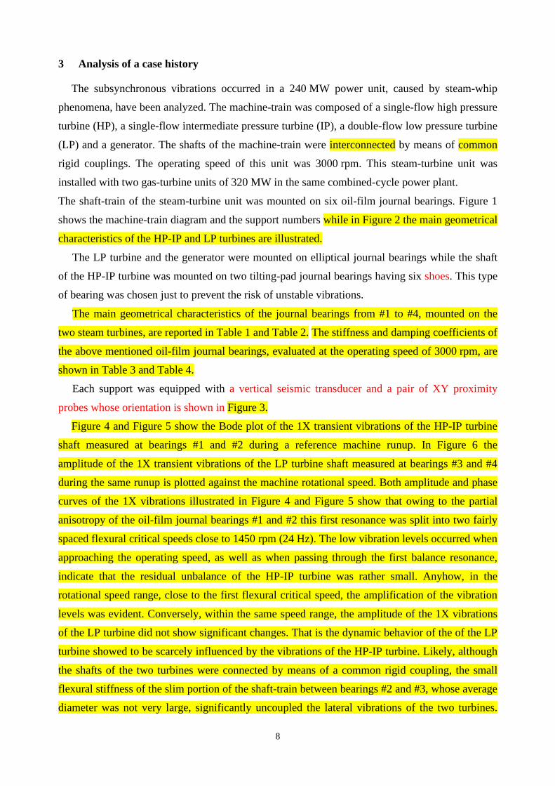
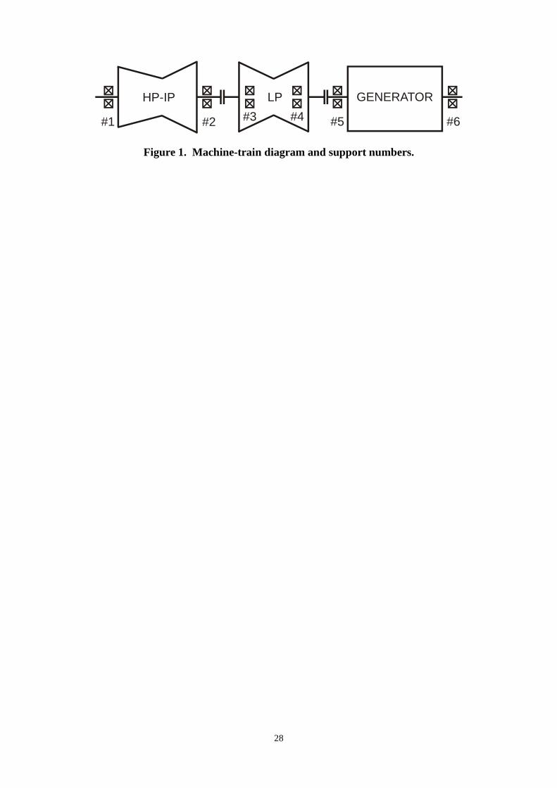
The shaft-train of the steam-turbine unit was mounted on six oil-film journal bearings. Figure 1
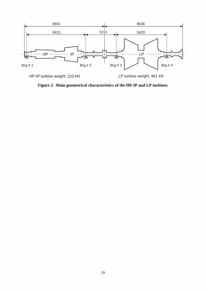
shows the machine-train diagram and the support numbers while in Figure 2 the main geometrical
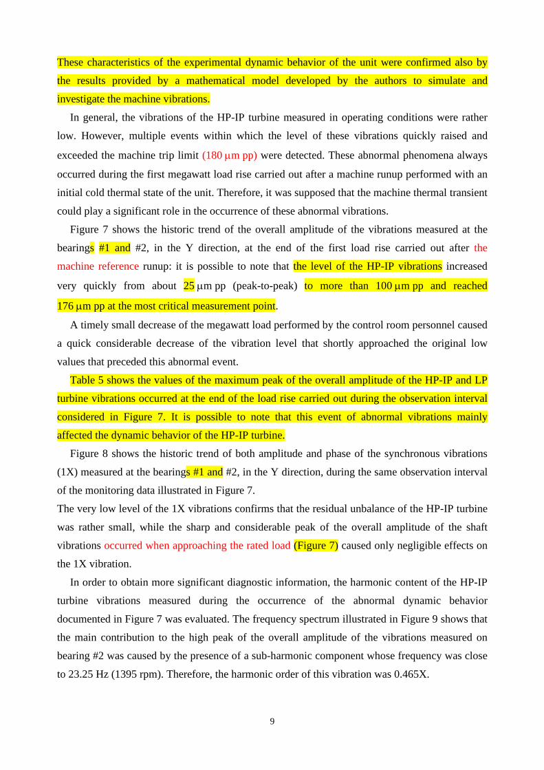
characteristics of the HP-IP and LP turbines are illustrated.
The LP turbine and the generator were mounted on elliptical journal bearings while the shaft
of the HP-IP turbine was mounted on two tilting-pad journal bearings having six shoes. This type
of bearing was chosen just to prevent the risk of unstable vibrations.
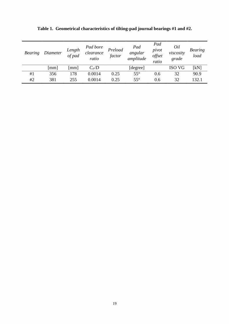
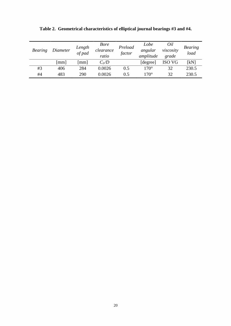
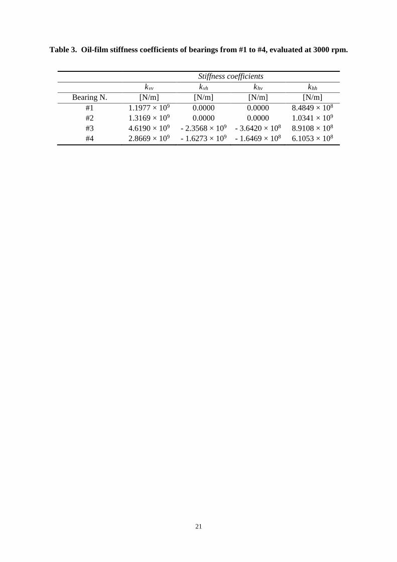
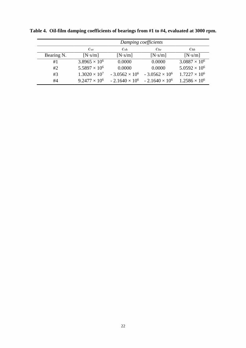
The main geometrical characteristics of the journal bearings from #1 to #4, mounted on the
two steam turbines, are reported in Table 1 and Table 2. The stiffness and damping coefficients of
the above mentioned oil-film journal bearings, evaluated at the operating speed of 3000 rpm, are
shown in Table 3 and Table 4.
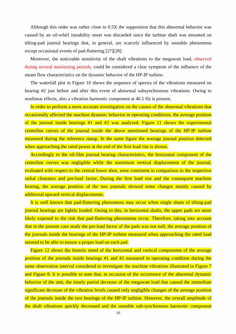
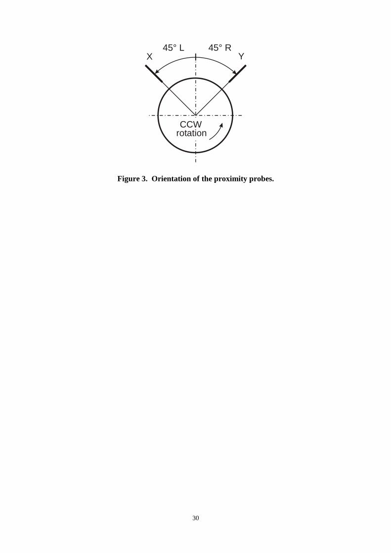
Each support was equipped with a vertical seismic transducer and a pair of XY proximity
probes whose orientation is shown in Figure 3.
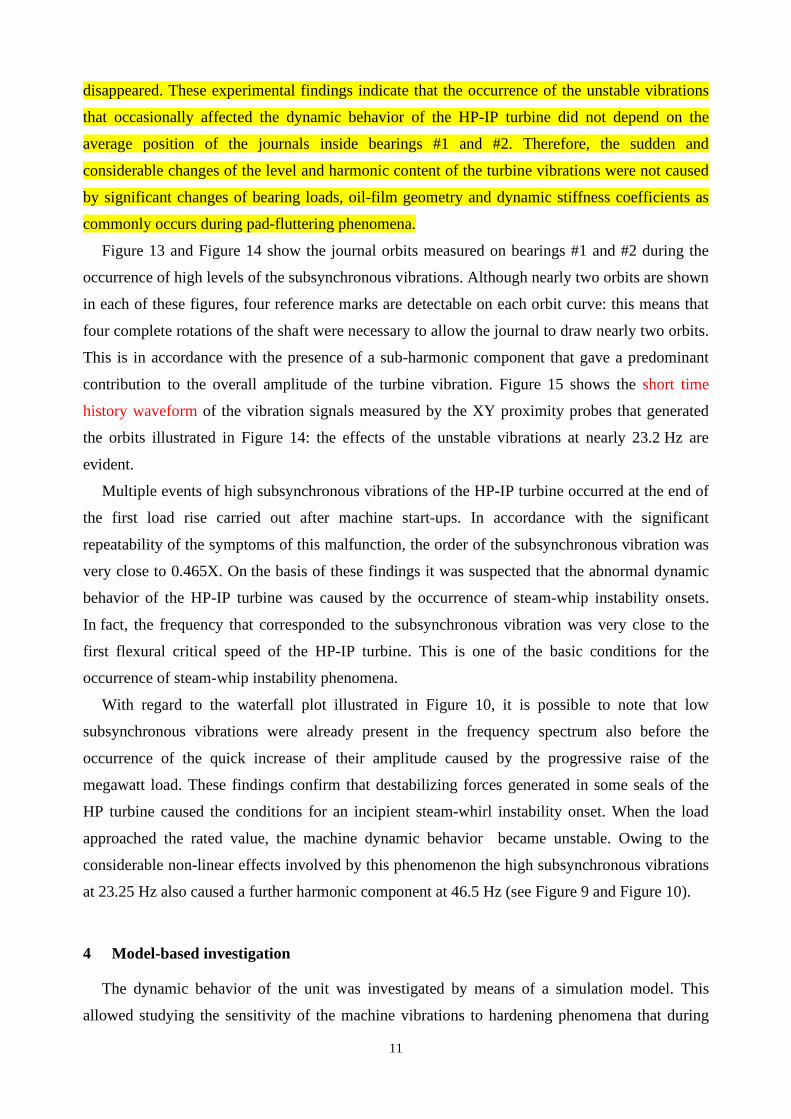
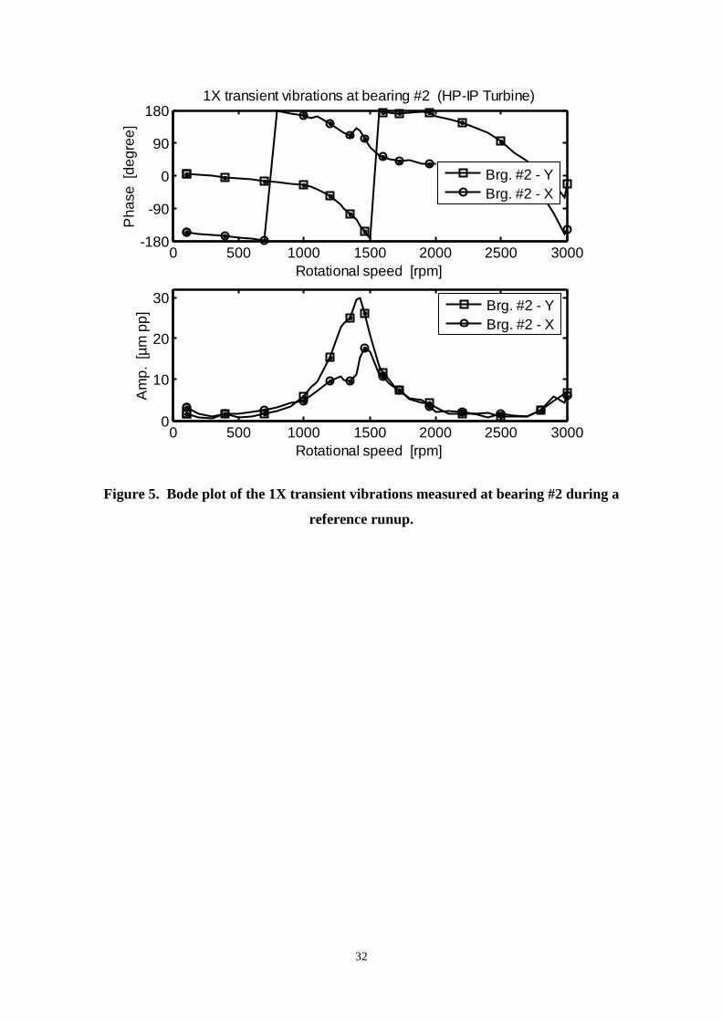
Figure 4 and Figure 5 show the Bode plot of the 1X transient vibrations of the HP-IP turbine
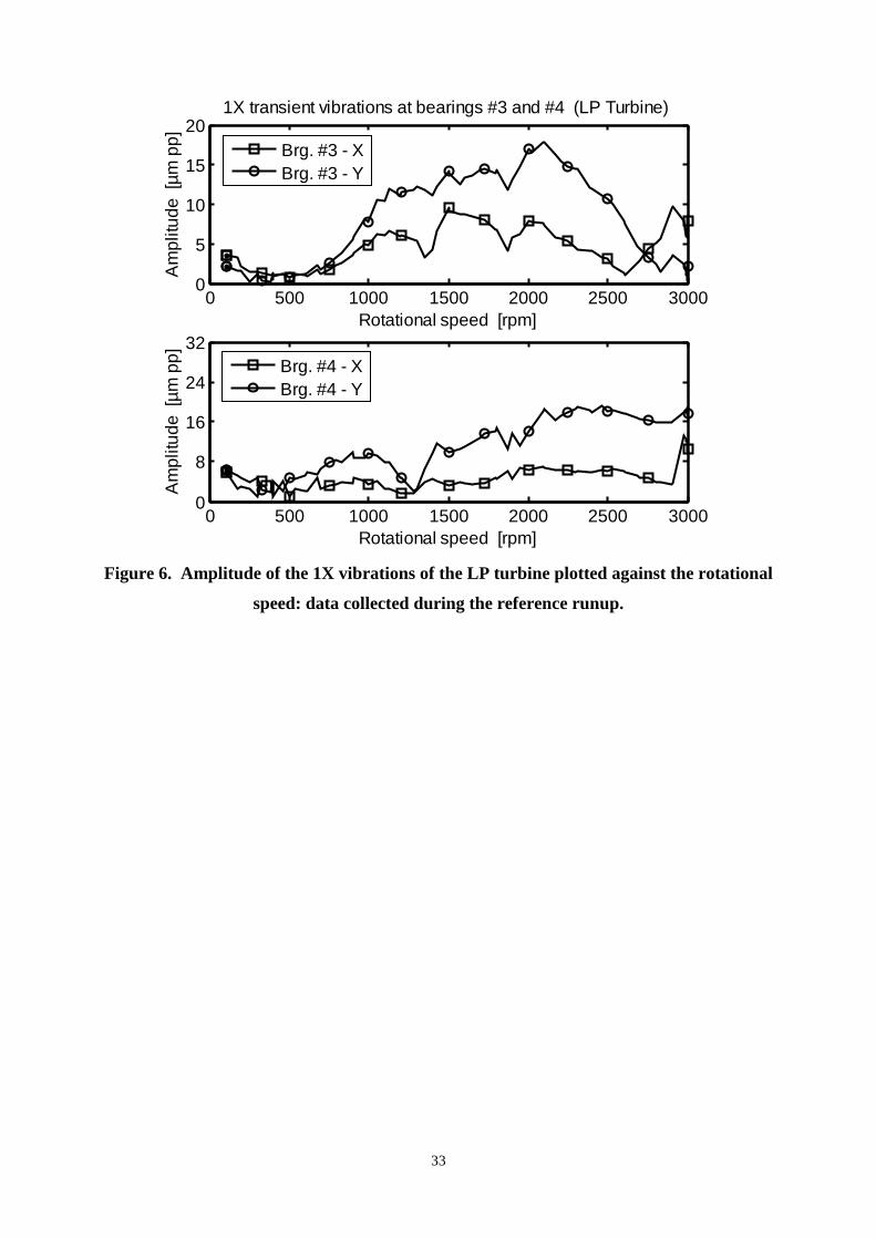
shaft measured at bearings #1 and #2 during a reference machine runup. In Figure 6 the
amplitude of the 1X transient vibrations of the LP turbine shaft measured at bearings #3 and #4
during the same runup is plotted against the machine rotational speed. Both amplitude and phase
curves of the 1X vibrations illustrated in Figure 4 and Figure 5 show that owing to the partial
anisotropy of the oil-film journal bearings #1 and #2 this first resonance was split into two fairly
spaced flexural critical speeds close to 1450 rpm (24 Hz). The low vibration levels occurred when
approaching the operating speed, as well as when passing through the first balance resonance,
indicate that the residual unbalance of the HP-IP turbine was rather small. Anyhow, in the
rotational speed range, close to the first flexural critical speed, the amplification of the vibration
levels was evident. Conversely, within the same speed range, the amplitude of the 1X vibrations
of the LP turbine did not show significant changes. That is the dynamic behavior of the of the LP
turbine showed to be scarcely influenced by the vibrations of the HP-IP turbine. Likely, although
the shafts of the two turbines were connected by means of a common rigid coupling, the small
flexural stiffness of the slim portion of the shaft-train between bearings #2 and #3, whose average
diameter was not very large, significantly uncoupled the lateral vibrations of the two turbines.
9
These characteristics of the experimental dynamic behavior of the unit were confirmed also by
the results provided by a mathematical model developed by the authors to simulate and
investigate the machine vibrations.
In general, the vibrations of the HP-IP turbine measured in operating conditions were rather
low. However, multiple events within which the level of these vibrations quickly raised and
exceeded the machine trip limit (180 µm pp) were detected. These abnormal phenomena always
occurred during the first megawatt load rise carried out after a machine runup performed with an
initial cold thermal state of the unit. Therefore, it was supposed that the machine thermal transient
could play a significant role in the occurrence of these abnormal vibrations.
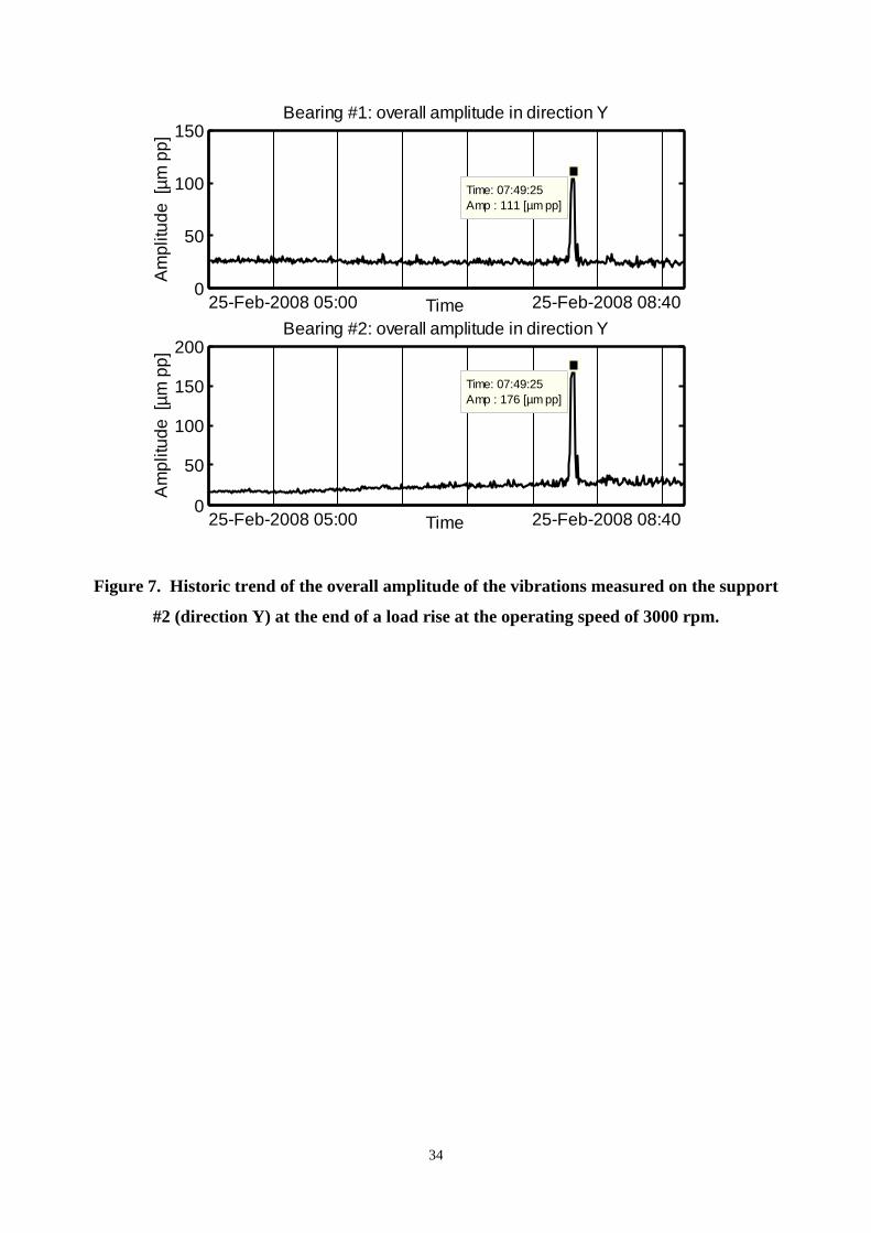
Figure 7 shows the historic trend of the overall amplitude of the vibrations measured at the
bearings #1 and #2, in the Y direction, at the end of the first load rise carried out after the
machine reference runup: it is possible to note that the level of the HP-IP vibrations increased
very quickly from about 25 µm pp (peak-to-peak) to more than 100 µm pp and reached
176 µm pp at the most critical measurement point.
A timely small decrease of the megawatt load performed by the control room personnel caused
a quick considerable decrease of the vibration level that shortly approached the original low
values that preceded this abnormal event.
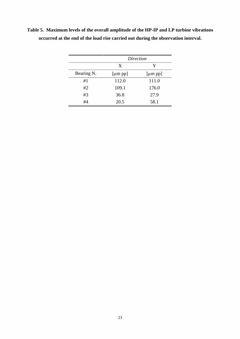
Table 5 shows the values of the maximum peak of the overall amplitude of the HP-IP and LP
turbine vibrations occurred at the end of the load rise carried out during the observation interval
considered in Figure 7. It is possible to note that this event of abnormal vibrations mainly
affected the dynamic behavior of the HP-IP turbine.
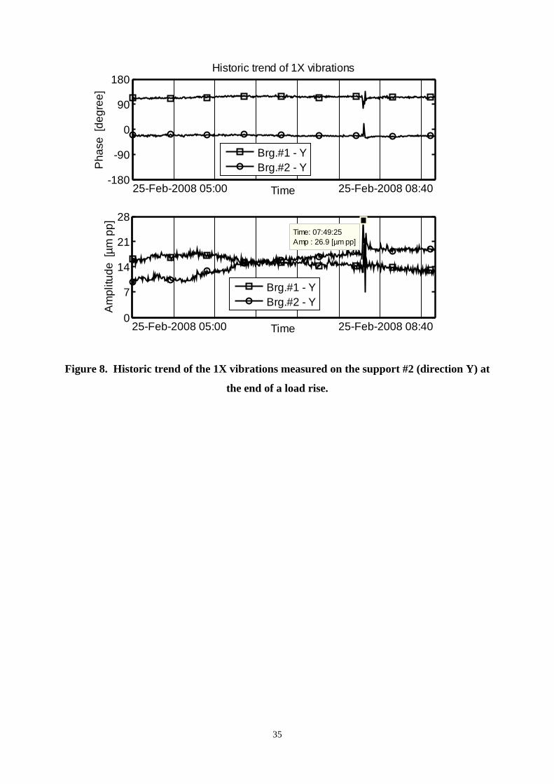
Figure 8 shows the historic trend of both amplitude and phase of the synchronous vibrations
(1X) measured at the bearings #1 and #2, in the Y direction, during the same observation interval
of the monitoring data illustrated in Figure 7.
The very low level of the 1X vibrations confirms that the residual unbalance of the HP-IP turbine
was rather small, while the sharp and considerable peak of the overall amplitude of the shaft
vibrations occurred when approaching the rated load (Figure 7) caused only negligible effects on
the 1X vibration.
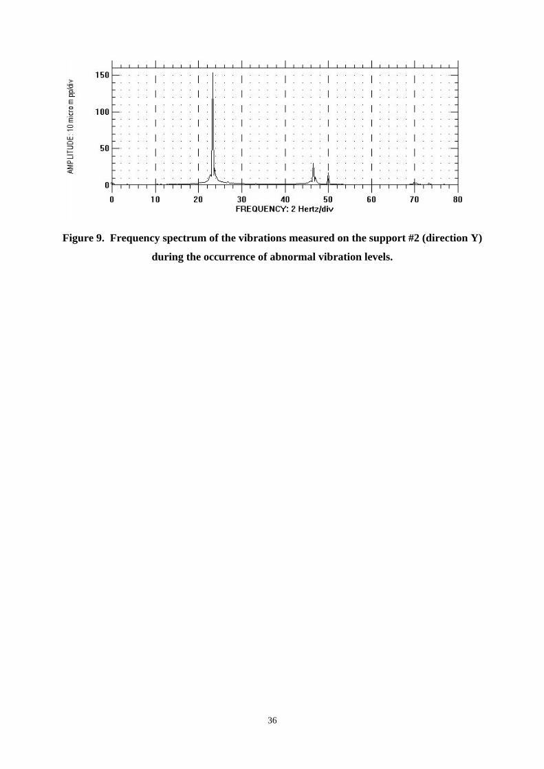
In order to obtain more significant diagnostic information, the harmonic content of the HP-IP
turbine vibrations measured during the occurrence of the abnormal dynamic behavior
documented in Figure 7 was evaluated. The frequency spectrum illustrated in Figure 9 shows that
the main contribution to the high peak of the overall amplitude of the vibrations measured on
bearing #2 was caused by the presence of a sub-harmonic component whose frequency was close
to 23.25 Hz (1395 rpm). Therefore, the harmonic order of this vibration was 0.465X.
10
Although this order was rather close to 0.5X the supposition that this abnormal behavior was
caused by an oil-whirl instability onset was discarded since the turbine shaft was mounted on
tilting-pad journal bearings that, in general, are scarcely influenced by unstable phenomena
except occasional events of pad-fluttering [27][28].
Moreover, the noticeable sensitivity of the shaft vibrations to the megawatt load, observed
during several monitoring periods, could be considered a clear symptom of the influence of the
steam flow characteristics on the dynamic behavior of the HP-IP turbine.
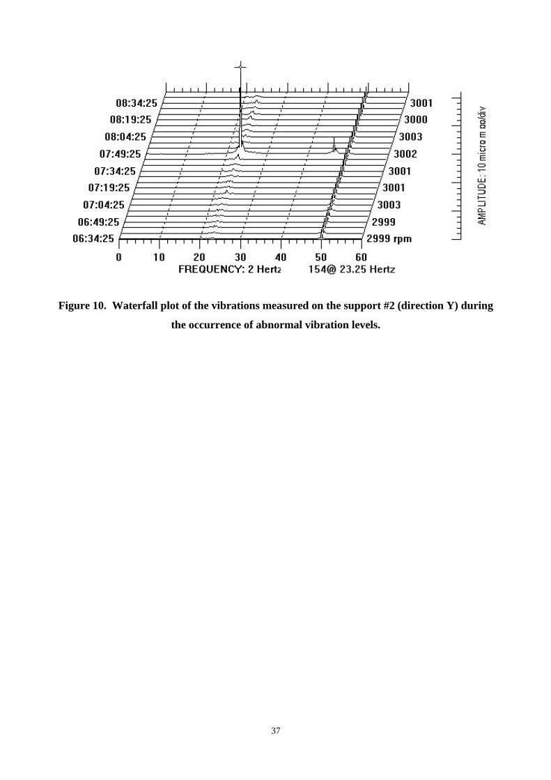
The waterfall plot in Figure 10 shows the sequence of spectra of the vibrations measured on
bearing #2 just before and after this event of abnormal subsynchronous vibrations. Owing to
nonlinear effects, also a vibration harmonic component at 46.5 Hz is present.
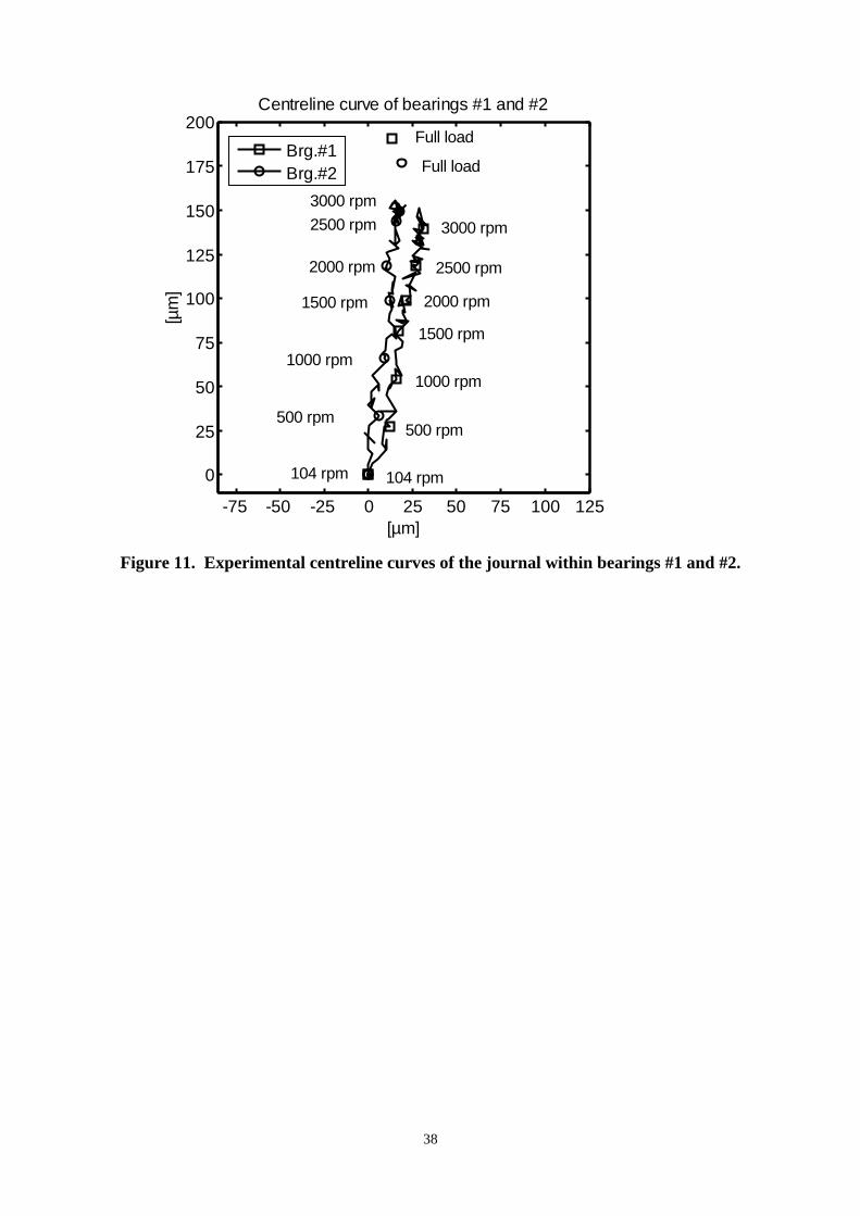
In order to perform a more accurate investigation on the causes of the abnormal vibrations that
occasionally affected the machine dynamic behavior in operating conditions, the average position
of the journal inside bearings #1 and #2 was analyzed. Figure 11 shows the experimental
centerline curves of the journal inside the above mentioned bearings of the HP-IP turbine
measured during the reference runup. In the same figure the average journal position detected
when approaching the rated power at the end of the first load rise is shown.
Accordingly to the oil-film journal bearing characteristics, the horizontal component of the
centerline curves was negligible while the maximum vertical displacement of the journal,
evaluated with respect to the central lower shoe, were consistent in comparison to the respective
radial clearance and pre-load factor. During the first load rise and the consequent machine
heating, the average position of the two journals showed some changes mainly caused by
additional upward vertical displacements.
It is well known that pad-fluttering phenomena may occur when single shoes of tilting-pad
journal bearings are lightly loaded. Owing to this, in horizontal shafts, the upper pads are more
likely exposed to the risk that pad-fluttering phenomena occur. Therefore, taking into account
that in the present case study the pre-load factor of the pads was not null, the average position of
the journals inside the bearings of the HP-IP turbine measured when approaching the rated load
seemed to be able to ensure a proper load on each pad.
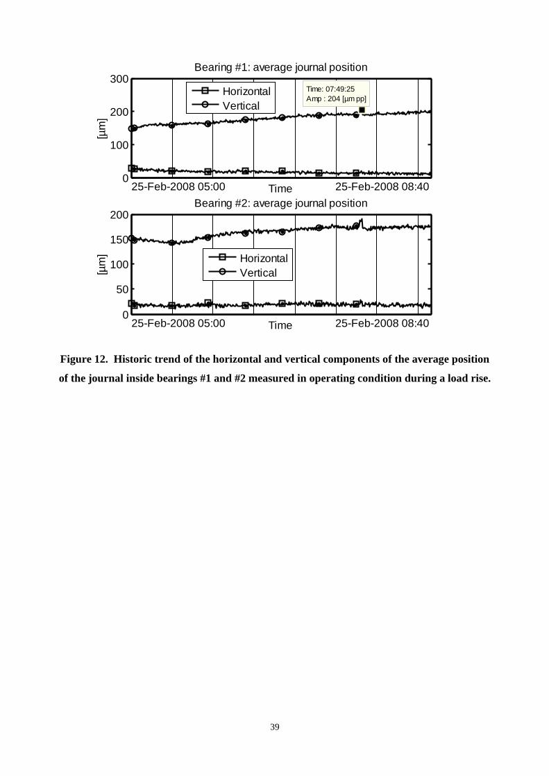
Figure 12 shows the historic trend of the horizontal and vertical components of the average
position of the journals inside bearings #1 and #2 measured in operating condition during the
same observation interval considered to investigate the machine vibrations illustrated in Figure 7
and Figure 8. It is possible to note that, in occasion of the occurrence of the abnormal dynamic
behavior of the unit, the timely partial decrease of the megawatt load that caused the immediate
significant decrease of the vibration levels caused only negligible changes of the average position
of the journals inside the two bearings of the HP-IP turbine. However, the overall amplitude of
the shaft vibrations quickly decreased and the unstable sub-synchronous harmonic component
11
disappeared. These experimental findings indicate that the occurrence of the unstable vibrations
that occasionally affected the dynamic behavior of the HP-IP turbine did not depend on the
average position of the journals inside bearings #1 and #2. Therefore, the sudden and
considerable changes of the level and harmonic content of the turbine vibrations were not caused
by significant changes of bearing loads, oil-film geometry and dynamic stiffness coefficients as
commonly occurs during pad-fluttering phenomena.
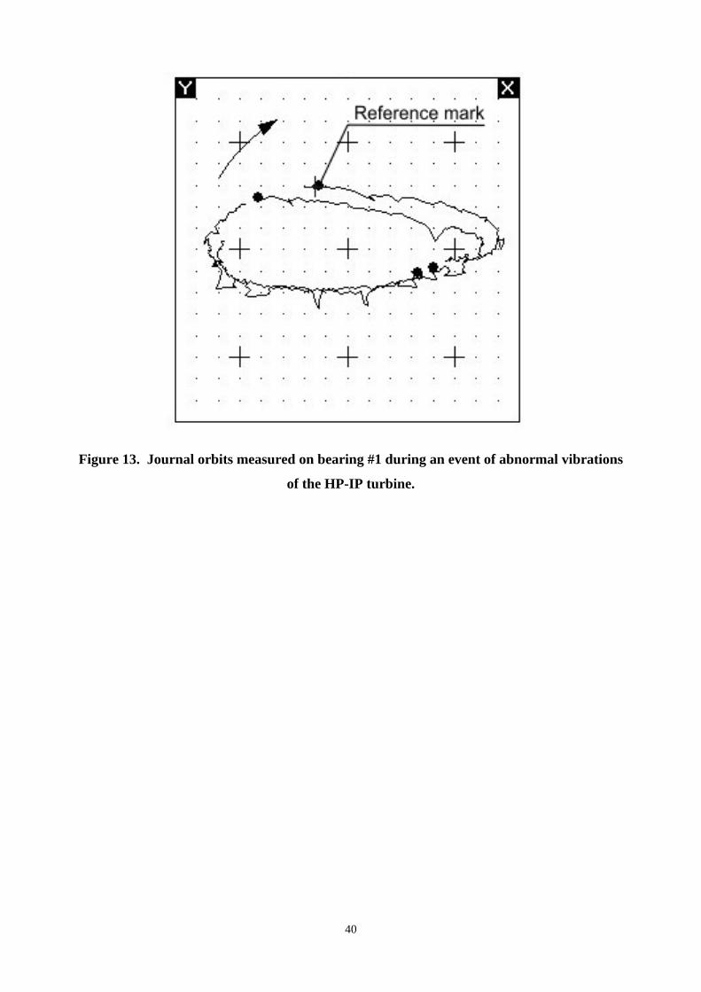
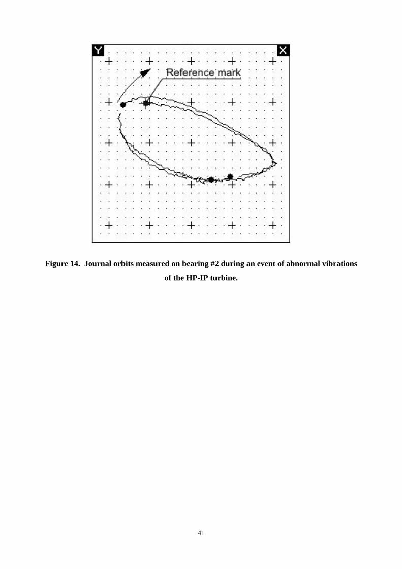
Figure 13 and Figure 14 show the journal orbits measured on bearings #1 and #2 during the
occurrence of high levels of the subsynchronous vibrations. Although nearly two orbits are shown
in each of these figures, four reference marks are detectable on each orbit curve: this means that
four complete rotations of the shaft were necessary to allow the journal to draw nearly two orbits.
This is in accordance with the presence of a sub-harmonic component that gave a predominant
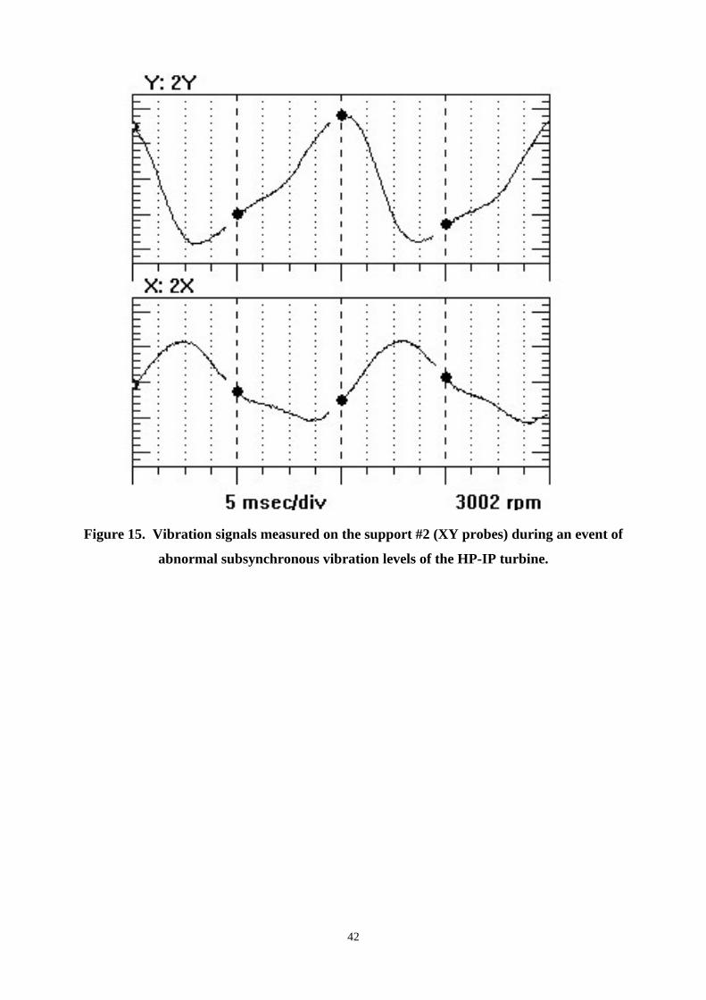
contribution to the overall amplitude of the turbine vibration. Figure 15 shows the short time
history waveform of the vibration signals measured by the XY proximity probes that generated
the orbits illustrated in Figure 14: the effects of the unstable vibrations at nearly 23.2 Hz are
evident.
Multiple events of high subsynchronous vibrations of the HP-IP turbine occurred at the end of
the first load rise carried out after machine start-ups. In accordance with the significant
repeatability of the symptoms of this malfunction, the order of the subsynchronous vibration was
very close to 0.465X. On the basis of these findings it was suspected that the abnormal dynamic
behavior of the HP-IP turbine was caused by the occurrence of steam-whip instability onsets.
In fact, the frequency that corresponded to the subsynchronous vibration was very close to the
first flexural critical speed of the HP-IP turbine. This is one of the basic conditions for the
occurrence of steam-whip instability phenomena.
With regard to the waterfall plot illustrated in Figure 10, it is possible to note that low
subsynchronous vibrations were already present in the frequency spectrum also before the
occurrence of the quick increase of their amplitude caused by the progressive raise of the
megawatt load. These findings confirm that destabilizing forces generated in some seals of the
HP turbine caused the conditions for an incipient steam-whirl instability onset. When the load
approached the rated value, the machine dynamic behavior became unstable. Owing to the
considerable non-linear effects involved by this phenomenon the high subsynchronous vibrations
at 23.25 Hz also caused a further harmonic component at 46.5 Hz (see Figure 9 and Figure 10).
4 Model-based investigation
The dynamic behavior of the unit was investigated by means of a simulation model. This
allowed studying the sensitivity of the machine vibrations to hardening phenomena that during
12
load rises can affect the stiffness coefficients of the seals mounted on the steam turbines as well
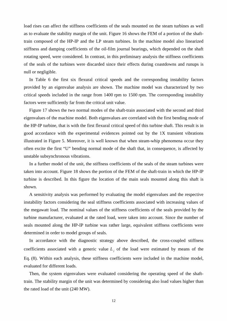
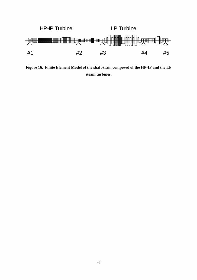
as to evaluate the stability margin of the unit. Figure 16 shows the FEM of a portion of the shaft-
train composed of the HP-IP and the LP steam turbines. In the machine model also linearized
stiffness and damping coefficients of the oil-film journal bearings, which depended on the shaft
rotating speed, were considered. In contrast, in this preliminary analysis the stiffness coefficients
of the seals of the turbines were discarded since their effects during coastdowns and runups is
null or negligible.
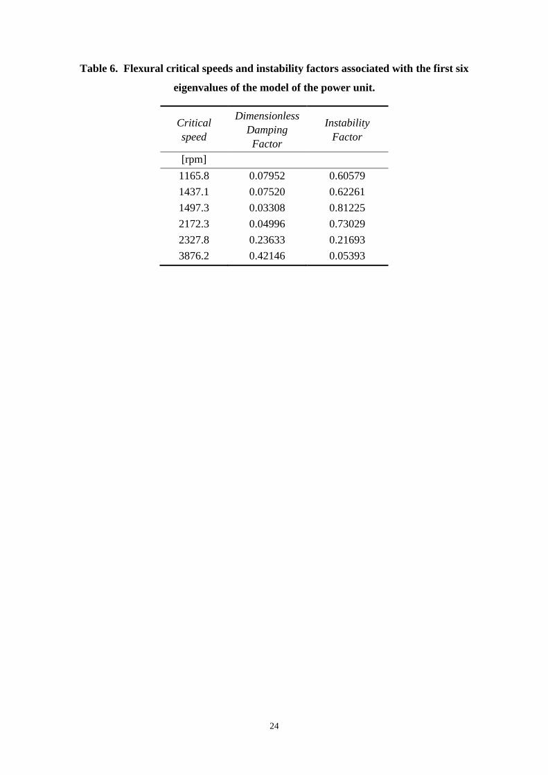
In Table 6 the first six flexural critical speeds and the corresponding instability factors
provided by an eigenvalue analysis are shown. The machine model was characterized by two
critical speeds included in the range from 1400 rpm to 1500 rpm. The corresponding instability
factors were sufficiently far from the critical unit value.
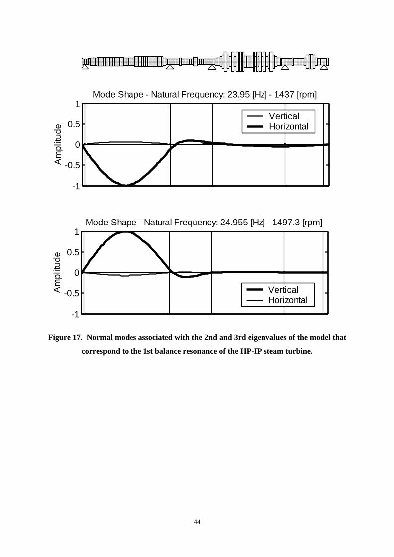
Figure 17 shows the two normal modes of the shaft-train associated with the second and third
eigenvalues of the machine model. Both eigenvalues are correlated with the first bending mode of
the HP-IP turbine, that is with the first flexural critical speed of this turbine shaft. This result is in
good accordance with the experimental evidences pointed out by the 1X transient vibrations
illustrated in Figure 5. Moreover, it is well known that when steam-whip phenomena occur they
often excite the first “U” bending normal mode of the shaft that, in consequence, is affected by
unstable subsynchronous vibrations.
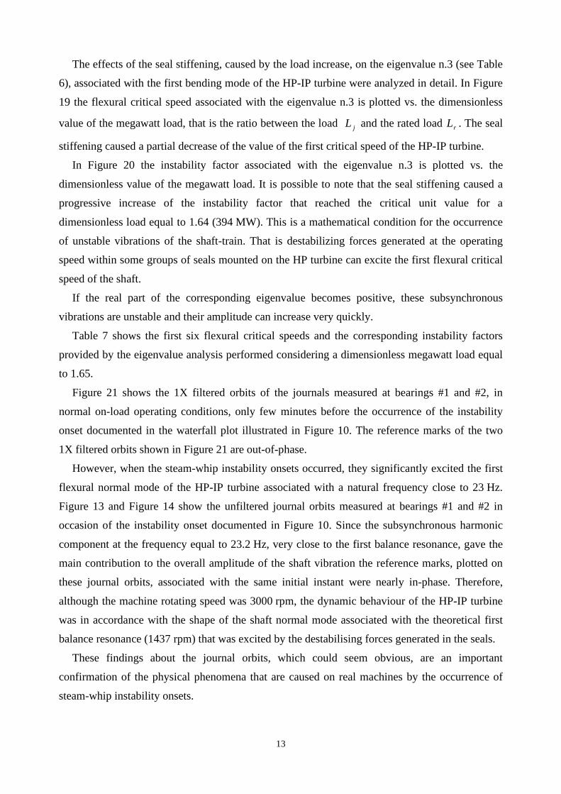
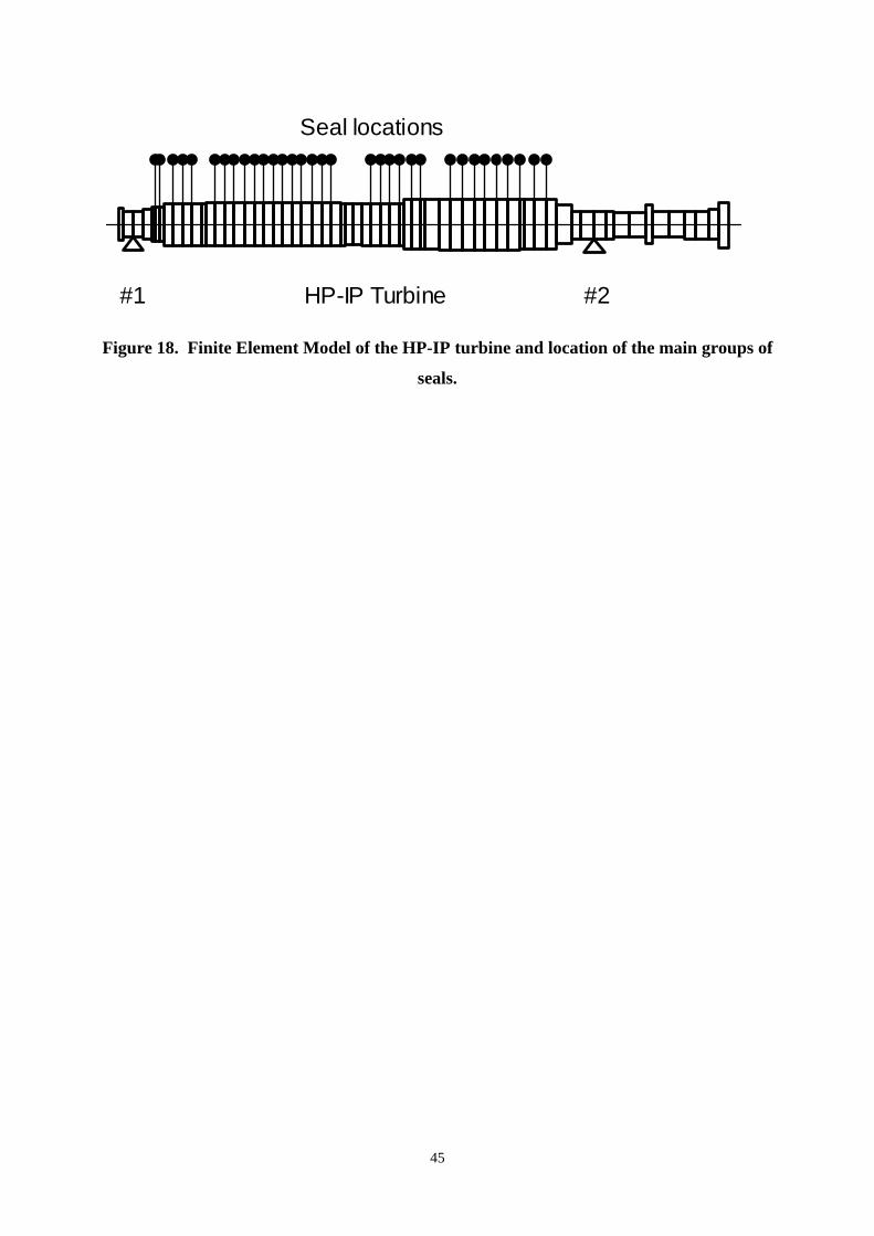
In a further model of the unit, the stiffness coefficients of the seals of the steam turbines were
taken into account. Figure 18 shows the portion of the FEM of the shaft-train in which the HP-IP
turbine is described. In this figure the location of the main seals mounted along this shaft is
shown.
A sensitivity analysis was performed by evaluating the model eigenvalues and the respective
instability factors considering the seal stiffness coefficients associated with increasing values of
the megawatt load. The nominal values of the stiffness coefficients of the seals provided by the
turbine manufacturer, evaluated at the rated load, were taken into account. Since the number of
seals mounted along the HP-IP turbine was rather large, equivalent stiffness coefficients were
determined in order to model groups of seals.
In accordance with the diagnostic strategy above described, the cross-coupled stiffness
coefficients associated with a generic value jL of the load were estimated by means of the
Eq. (8). Within each analysis, these stiffness coefficients were included in the machine model,
evaluated for different loads.
Then, the system eigenvalues were evaluated considering the operating speed of the shaft-
train. The stability margin of the unit was determined by considering also load values higher than
the rated load of the unit (240 MW).
13
The effects of the seal stiffening, caused by the load increase, on the eigenvalue n.3 (see Table
6), associated with the first bending mode of the HP-IP turbine were analyzed in detail. In Figure
19 the flexural critical speed associated with the eigenvalue n.3 is plotted vs. the dimensionless
value of the megawatt load, that is the ratio between the load jL and the rated load rL . The seal
stiffening caused a partial decrease of the value of the first critical speed of the HP-IP turbine.
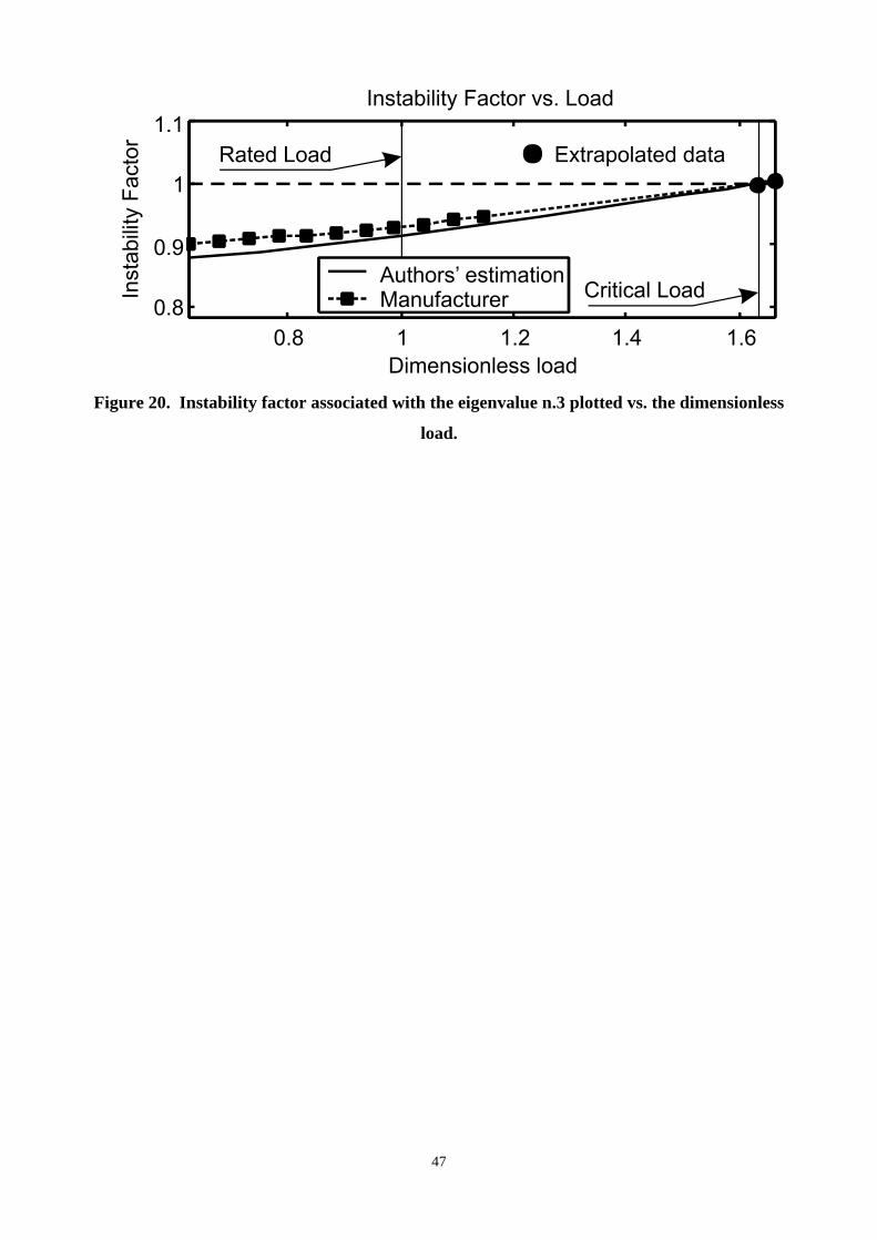
In Figure 20 the instability factor associated with the eigenvalue n.3 is plotted vs. the
dimensionless value of the megawatt load. It is possible to note that the seal stiffening caused a
progressive increase of the instability factor that reached the critical unit value for a
dimensionless load equal to 1.64 (394 MW). This is a mathematical condition for the occurrence
of unstable vibrations of the shaft-train. That is destabilizing forces generated at the operating
speed within some groups of seals mounted on the HP turbine can excite the first flexural critical
speed of the shaft.
If the real part of the corresponding eigenvalue becomes positive, these subsynchronous
vibrations are unstable and their amplitude can increase very quickly.
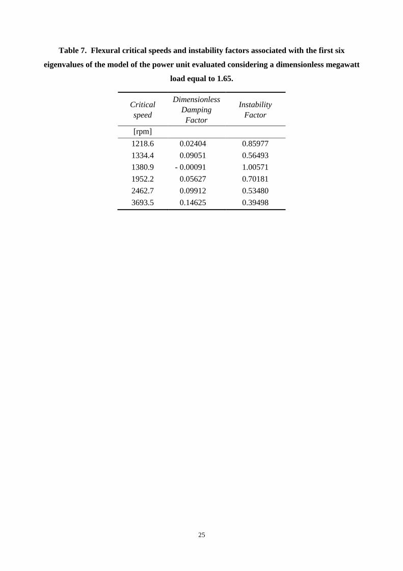
Table 7 shows the first six flexural critical speeds and the corresponding instability factors
provided by the eigenvalue analysis performed considering a dimensionless megawatt load equal
to 1.65.
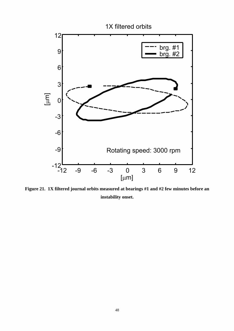
Figure 21 shows the 1X filtered orbits of the journals measured at bearings #1 and #2, in
normal on-load operating conditions, only few minutes before the occurrence of the instability
onset documented in the waterfall plot illustrated in Figure 10. The reference marks of the two
1X filtered orbits shown in Figure 21 are out-of-phase.
However, when the steam-whip instability onsets occurred, they significantly excited the first
flexural normal mode of the HP-IP turbine associated with a natural frequency close to 23 Hz.
Figure 13 and Figure 14 show the unfiltered journal orbits measured at bearings #1 and #2 in
occasion of the instability onset documented in Figure 10. Since the subsynchronous harmonic
component at the frequency equal to 23.2 Hz, very close to the first balance resonance, gave the
main contribution to the overall amplitude of the shaft vibration the reference marks, plotted on
these journal orbits, associated with the same initial instant were nearly in-phase. Therefore,
although the machine rotating speed was 3000 rpm, the dynamic behaviour of the HP-IP turbine
was in accordance with the shape of the shaft normal mode associated with the theoretical first
balance resonance (1437 rpm) that was excited by the destabilising forces generated in the seals.
These findings about the journal orbits, which could seem obvious, are an important
confirmation of the physical phenomena that are caused on real machines by the occurrence of
steam-whip instability onsets.
14
A protection system that causes a sudden machine trip as well as a timely decrease of the
megawatt load, and then of the stiffness coefficients of the seals, can avoid the occurrence of
catastrophic failures.
In Figure 20 the instability factor curve evaluated by the authors is compared to the respective
curve that the turbine manufacturer provided only in the range below a dimensionless load equal
to 1.14. However, on the basis of the available data it was possible to extrapolate a reliable
estimate of the instability factor associated with the critical dimensionless load of 1.64 identified
by the authors. The result of this investigation is a prediction of the instability factor that the
model of the turbine manufacturer would have given if the analysis was performed over a larger
load range. This extrapolated value of the instability factor is very close to unity. Therefore, the
results of the sensitivity analysis performed by the authors are in good accordance with those
obtained by the turbine manufacturer.
The stability margin obtained by means of both investigations is close to 0.64: larger safety
margins, e.g. higher than 1.5, and would have been necessary to reduce the risk of steam-whip
instability onsets, machine outages and serious damage.
In the present case study it is possible to suppose that the significant thermal transient that
affected the unit during the first load rise carried out at the end of a machine start-up caused a
temporary critical alignment condition of the shaft-train with respect to the turbine casing. Likely,
owing to this the clearance of some groups of seals of the HP turbine could reach abnormal
values causing an excessive unexpected hardening of the cross-coupled stiffness coefficients of
the seals. Therefore, in this abnormal operating condition, even at megawatt loads close to the
rated load (240 MW), it could be possible to generate the critical situation that with an ideal
rotor-to-seal alignment would occur with a virtual load close to 400 MW as indicated by the
model predictions.
With regard to the capability of the seal stiffening to generate a system eigenvalue
characterized by a positive real part, which can cause unstable vibrations, excessively low values
of the flexural stiffness of the turbine shaft can cause detrimental effects. Often the rotor of the
HP turbines are rather slim. Therefore, the increase of the flexural stiffness, caused by even a
small increase of the average diameter of the shaft, can be sufficient to significantly reduce the
sensitivity of the turbine dynamic behavior to steam-whip instability phenomena. In accordance
with this assumption the experimental value of the first balance resonance of the HP-IP turbine
analyzed in the present case study was rather low (nearly 1480 rpm).
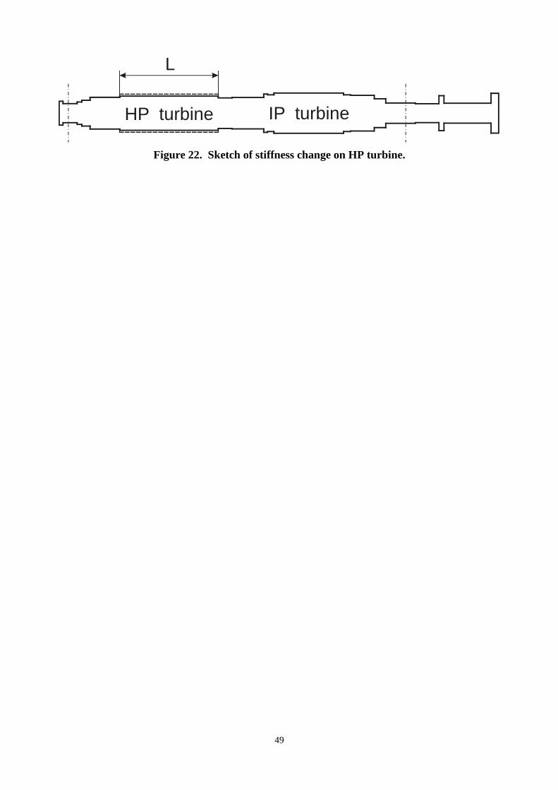
A further investigation was performed to study the sensitivity of the risk of the occurrence of
steam-whip instability phenomena to changes of the flexural stiffness of the HP-IP turbine.
Obviously fluid-dynamic restrictions limit the extent of the increase in the average diameter of
the shaft. Therefore, in the present case study the diameter of the main body of the HP turbine,
15
where fourteen bladed disks and a large number of seals are mounted, was increased of only 15
per cent (Figure 22).
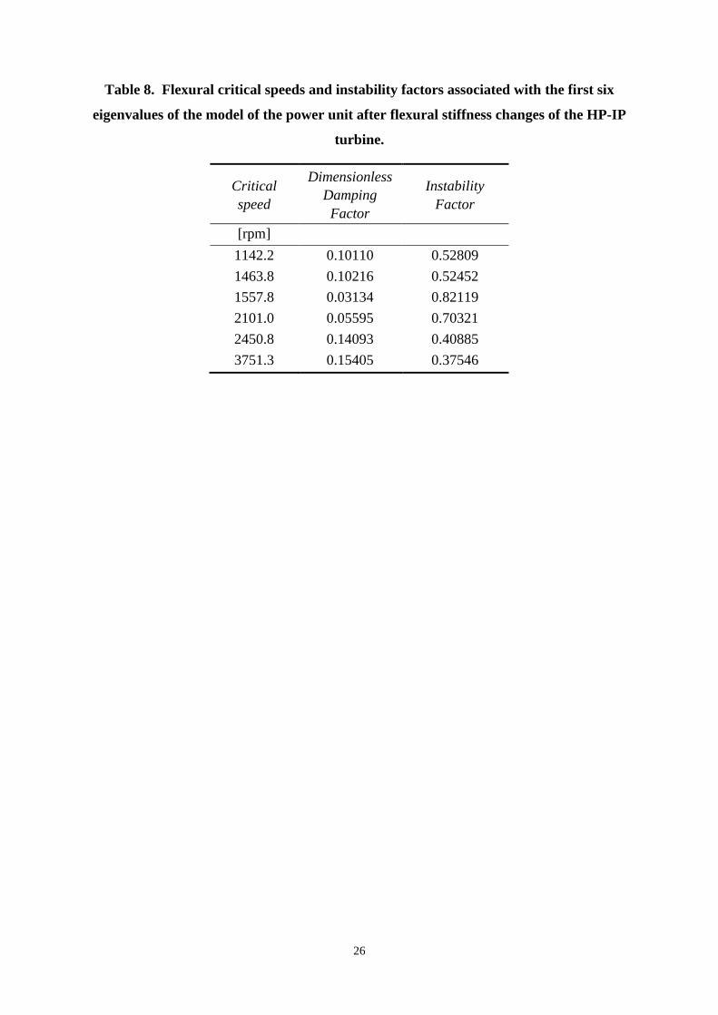
This modified HP turbine shaft was considered into a new simulation model. The first six
flexural critical speeds of the modified shaft-train are reported in Table 8: these results can be
compared to those shown in Table 6. Obviously, the partial increase of the diameter of the main
body of the HP turbine causes a small increase of the second and third critical speeds of the shaft-
train that are associated with the first “U” bending mode of the HP-IP turbine.
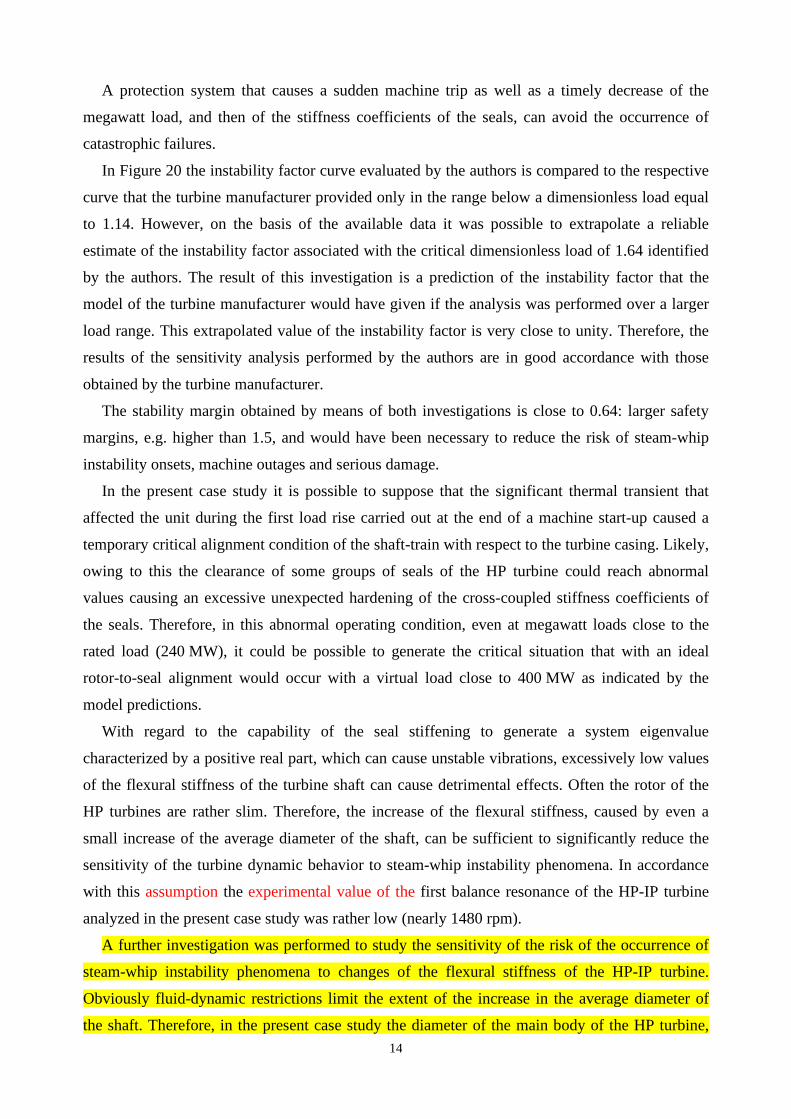
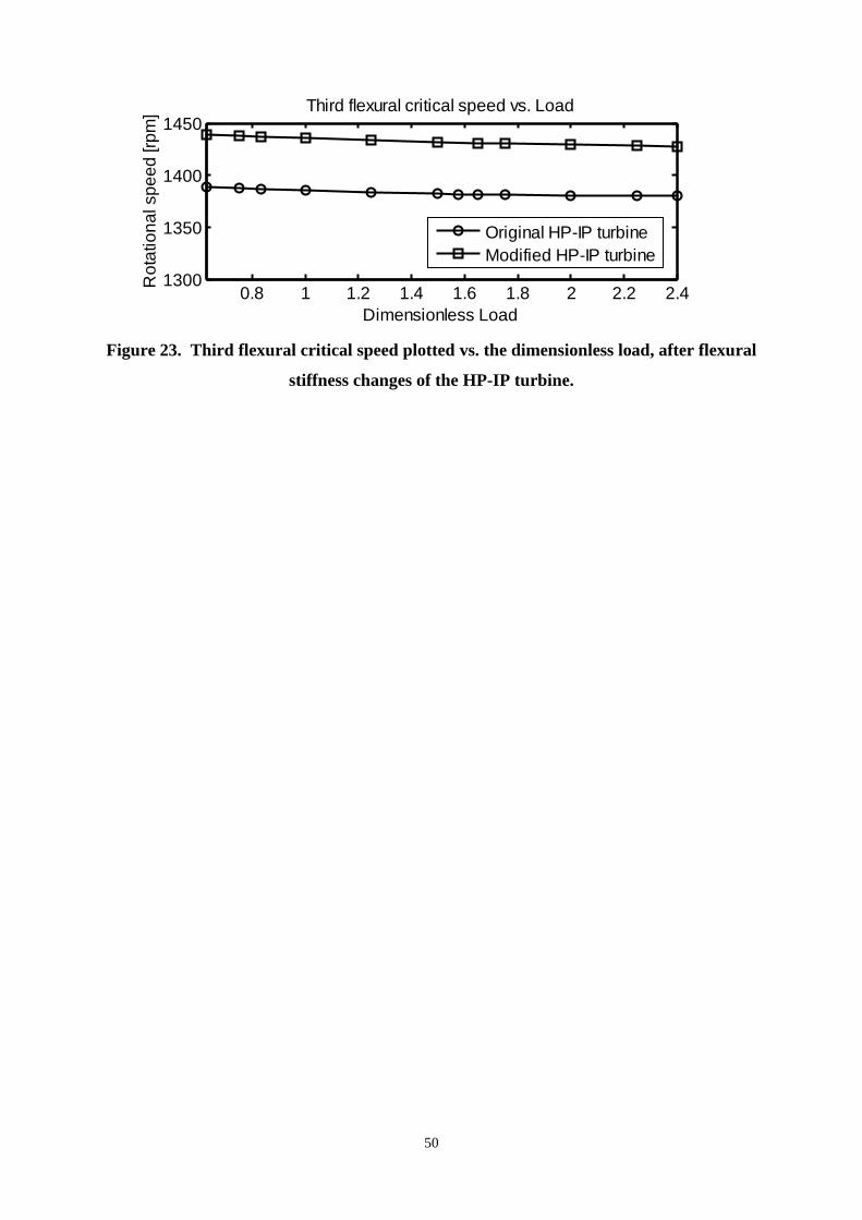
Then, the eigenvalues and eigenmodes of the machine model were evaluated considering a
shaft rotational speed equal to the operating speed and increasing values of the dimensionless
load. In Figure 23 the third flexural critical speed of the shaft-train is plotted against the
dimensionless load. In the same figure, these results are compared to those obtained in the same
conditions by means of the original model of the shaft-train. The small increase of the diameter of
the HP turbine caused an increase of about 3.6% of the third flexural critical speed.
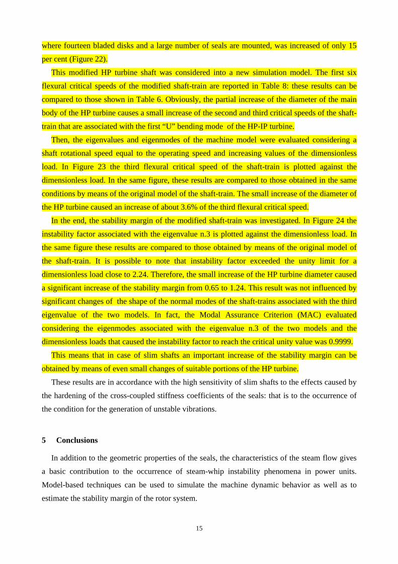
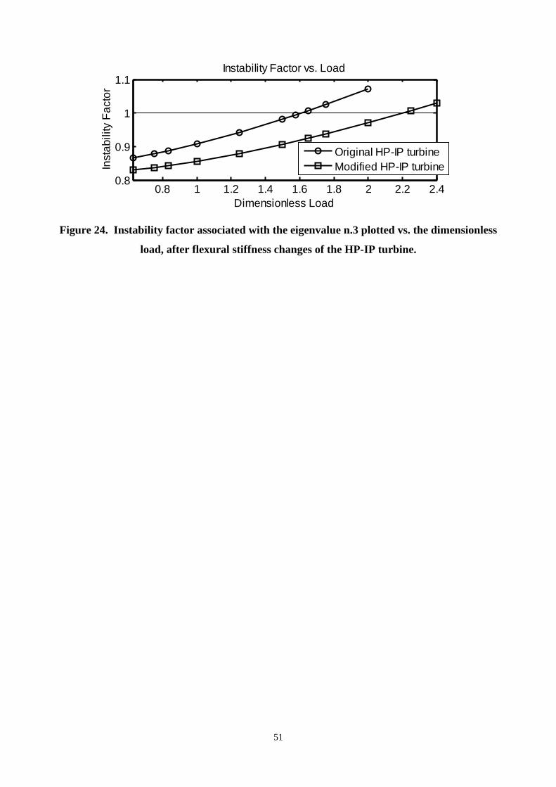
In the end, the stability margin of the modified shaft-train was investigated. In Figure 24 the
instability factor associated with the eigenvalue n.3 is plotted against the dimensionless load. In
the same figure these results are compared to those obtained by means of the original model of
the shaft-train. It is possible to note that instability factor exceeded the unity limit for a
dimensionless load close to 2.24. Therefore, the small increase of the HP turbine diameter caused
a significant increase of the stability margin from 0.65 to 1.24. This result was not influenced by
significant changes of the shape of the normal modes of the shaft-trains associated with the third
eigenvalue of the two models. In fact, the Modal Assurance Criterion (MAC) evaluated
considering the eigenmodes associated with the eigenvalue n.3 of the two models and the
dimensionless loads that caused the instability factor to reach the critical unity value was 0.9999.
This means that in case of slim shafts an important increase of the stability margin can be
obtained by means of even small changes of suitable portions of the HP turbine.
These results are in accordance with the high sensitivity of slim shafts to the effects caused by
the hardening of the cross-coupled stiffness coefficients of the seals: that is to the occurrence of
the condition for the generation of unstable vibrations.
5 Conclusions
In addition to the geometric properties of the seals, the characteristics of the steam flow gives
a basic contribution to the occurrence of steam-whip instability phenomena in power units.
Model-based techniques can be used to simulate the machine dynamic behavior as well as to
estimate the stability margin of the rotor system.
16
The hardening of the cross-coupled stiffness coefficients of the seals caused by a rise of the
steam pressure and flow can cause important changes in the eigenvalues and eigenmodes of the
mathematical model of the rotating machine. A parametric analysis can be performed to
determine the threshold level of the steam flow that causes the real part of the eigenvalue
associated with the first flexural normal mode of the turbine shaft to become positive. This causes
the conditions for the occurrence of unstable vibrations.
Seal misalignments, e.g. induced by the thermal transients that can affect power units during
load rises, can cause unexpected and undesired values of the seal stiffness coefficients, which can
reach higher levels in comparison to the corresponding reference values obtained considering an
ideal rotor-to-seal alignment.
The sensitivity of the stability margin of the machine-train on seal misalignments can be
studied with model-based techniques. This strategy allows the changes in the eigenvalues and
eigenmodes of the rotor system due to changes in the seal stiffness coefficients to be investigated.
In this paper the results of the analysis of the stability margin of a large power unit that was
affected by unstable vibrations in on-load operating conditions caused by steam-whirl instability
phenomena have been shown and discussed. The effects on the eigenvalues and eigenmodes of
the machine model caused by seal misalignments and raises of the steam flow have been
simulated. The results of these investigations are in good accordance with the value of the
stability margin obtained on the basis of the experimental findings.
6 References
[1] Yamamoto T., Ishida Y,. “Linear and Nonlinear Rotordynamics”, John Wiley & Sons, Inc.,
New York, pp. 210-214.
[2] Capone, E., 1973, “Oil whirl in journal bearings under no load conditions”, Wear, Vol. 26
(2), pp. 207-217.
[3] Muszynska, A., 1986, “Whirl and Whip-Rotor/Bearing Stability Problems”, Journal of
Sound and Vibrations, Vol. 110 (3), pp. 443-462.
[4] Adams, M.L., 1978, “Keep rotor vibration under control”, Power, Vol. 122 (8), pp. 28-29.
[5] Krämer, E., 1968, “Selbsterregte Schwingungen von Wellen infolge Querkraefte (Self-
excited vibrations of shafts due to transverse forces)”, Brennst.-Waerme-Kraft, Vol. 20 (7).
[6] Kubiak Sz., J., Childs, D., Rodriguez, M., García, M.C., 2007, “Investigation into a "Steam
whirl" which affected HP rotors of 300 MW steam turbines”, Proceedings of the ASME
Power Conference 2007, p 291-298, 2007, July 17-19, 2007.
17
[7] Pollman, E., Schwerdtfeger, H., Termuehlen, H., 1978, “Flow excited vibrations in high
pressure turbines (Steam whirl)”, ASME Journal of Engineering for Power, Vol. 100 (2),
pp. 219-228.
[8] Thomas, H.J., 1958, “Instabile Eigenschwingungen von Turbinenlaeufern, angefacht durch
die Spaltstroemungen in Stopfbuchsen und Beschaufelungen (Unstable vibrations of turbine
rotors excited by clearance flows in sealings and bladings) ”, Bull. De l’AIM, vol. 71
(11/12), pp. 1039-1064.
[9] Alford, J., 1965, “Protecting turbomachinery from self-excited rotor whirl”, ASME Journal
of Engineering for Power, Vol. 87 (4), pp. 333-344.
[10] Bently, D. E., Muszynska, A., 1988, “Role of Circumferential Flow in the Stability of
Fluid-Handling Machine Rotors”, Proceedings of The Fifth Workshop on Rotordynamic
Instability Problems in High-Performance Turbomachinery, Texas, USA, NASA CP 3026,
pp. 415-430.
[11] Muszynska, A., 1990, “The Role of Flow-Related Tangential Forces in Rotor/Bearing/Seal
System Stability in the Stability of Fluid-Handling Machine Rotors”, Proceedings of the 3rd
International Symposium on Transport Phenomena and Dynamics of Rotating Machinery,
ISROMAC-3, Honolulu, Hawaii, USA.
[12] Muszynska, A., 1999, “Transition to Fluid-Induced Limit Cycle Self-Excited Vibration of a
Rotor and Instability Threshold ‘Hysteresis’”, International Journal of Rotating Machinery,
Vol. 5 (2), pp. 123-133.
[13] Childs, D.W., 1993, “Turbomachinery Rotordynamics – Phenomena, Modeling &
Analysis”, John Wiley & Sons, Inc., New York, pp. 227-354.
[14] Benckert, H., Wachter, J., 1980, “Flow induced spring constants of labyrinth seals”,
IMechE paper C258/80, pp. 53-63.
[15] Hauck, L., 1982, “Measurement and evaluation of swirl-type flow in labyrinth seals of
conventional turbine stages”, NASA Conference Publication, pp. 242-259.
[16] Hauck, L., 1981, “Vergleich gebraeuchlicher Tubinenstufen hinsichtlich des Auftretens
spaltstroemungsbedingter Kraefte (Comparison of usual turbine stages as regards clearance
flow induced forces)”, Konstruktion, Vol. 33 (2), pp. 59-64.
[17] Schettel, J., Nordmann, R., 2004, “Rotordynamics of turbine labyrinth seals - a comparison
of CFD models to experiments”, IMechE paper C623/018, pp. 13-22.
18
[18] Bachschmid, N., Pennacchi, P., Vania, A., 2006, “Steam whirl stability margin in a power
unit”, Proceedings of ISMA - Int. Conf. on Noise and Vibration Engineering, Leuven,
Belgium, ISBN 90-73802-83-0, pp. 3561-3575
[19] Bachschmid, N., Pennacchi, P., Vania, A., 2008, “Steam-whirl analysis in a high pressure
cylinder of a turbo generator”, Mechanical Systems and Signal Processing, Vol. 22 (1), pp.
121-132.
[20] Bently, D. E., Muszynska, A., 1990, “Frequency Swept Rotating Input Perturbation
Techniques and Identification of Fluid Force Models in Rotor/Bearing/ Seal Systems and
Fluid Handling Machines”, Journal of Sound and Vibration, Vol. 143 (1), pp. 103-124.
[21] Kanki, H., Fujii, H., Hizume, A., Ichimura, T., Yamamoto, T., 1986, “Solving
Nonsynchronous Vibration Problems of Large Rotating Machineries by Exciting Test in
Actual Operating Condition”, Proceedings of IFToMM International Conference on
Rotordynamics, Tokyo, Japan, pp. 221-225.
[22] Lalanne, M., Ferraris, G., 1998, “Rotordynamics Prediction in Engineering”, 2nd Edition,
John Wiley & Sons Ltd., Baffins Lane, Chichester, West Sussex PO19 1UD, England,
ISBN 0 471 92633 7.
[23] Vania, A., 2000, “On the identification of foundation of a large turbogenerator unit by the
analysis of transient vibrations”, Proceedings of IMECHE - 7th Int. Conf. on Vibrations in
Rotating Machinery, Nottingham, UK, C576/076/2000, pp. 313-322.
[24] Pennacchi, P., Bachschmid, N., Vania, A., Zanetta, G.A., Gregori, L., 2006, “Use of modal
representation for the supporting structure in model-based fault identification of large
rotating machinery: part 1 – theoretical remarks”, Mechanical Systems and Signal
Processing, Vol. 20 (3), pp. 662-681.
[25] Cavalca, K.L., Cavalcante, P.F., Okabe, E.P., 2005, “An investigation on the influence of
the supporting structure on the dynamics of the rotor system”, Mechanical Systems and
Signal Processing, Vol. 19 (1), pp. 157-174.
[26] Muszynska, A., 2005, “Rotordynamics”, Taylor & Francis Group, a CRC Press book, New
York, USA, ISBN 0 8247 2399 6.
[27] Hargreaves, D. J., Fillon, M., 2007, Analysis of a tilting pad journal bearing to avoid pad
fluttering, Tribology International, Vol. 40 (4), pp. 607-612.
[28] Yang, S. H., Kim, C., Lee, Y.-B., 2006, “Experimental study on the characteristics of pad
fluttering in a tilting pad journal bearing”, Tribology International, Vol. 39 (7), pp. 689-
694.
19
Table 1. Geometrical characteristics of tilting-pad journal bearings #1 and #2.
Bearing Diameter Length of pad
Pad bore clearance
ratio
Preload factor
Pad angular
amplitude
Pad pivot offset ratio
Oil viscosity
grade
Bearing load
[mm] [mm] Cp/D [degree] ISO VG [kN] #1 356 178 0.0014 0.25 55° 0.6 32 90.9 #2 381 255 0.0014 0.25 55° 0.6 32 132.1
20
Table 2. Geometrical characteristics of elliptical journal bearings #3 and #4.
Bearing Diameter Length of pad
Bore clearance
ratio
Preload factor
Lobe angular
amplitude
Oil viscosity
grade
Bearing load
[mm] [mm] Cp/D [degree] ISO VG [kN] #3 406 284 0.0026 0.5 170° 32 230.5 #4 483 290 0.0026 0.5 170° 32 230.5
21
Table 3. Oil-film stiffness coefficients of bearings from #1 to #4, evaluated at 3000 rpm.
Stiffness coefficients kvv kvh khv khh
Bearing N. [N/m] [N/m] [N/m] [N/m] #1 1.1977 × 10⁹ 0.0000 0.0000 8.4849 × 10⁸ #2 1.3169 × 10⁹ 0.0000 0.0000 1.0341 × 10⁹ #3 4.6190 × 10⁹ - 2.3568 × 10⁹ - 3.6420 × 10⁸ 8.9108 × 10⁸ #4 2.8669 × 10⁹ - 1.6273 × 10⁹ - 1.6469 × 10⁸ 6.1053 × 10⁸
22
Table 4. Oil-film damping coefficients of bearings from #1 to #4, evaluated at 3000 rpm.
Damping coefficients cvv cvh chv chh
Bearing N. [N·s/m] [N·s/m] [N·s/m] [N·s/m] #1 3.8965 × 10⁶ 0.0000 0.0000 3.0887 × 10⁶ #2 5.5897 × 10⁶ 0.0000 0.0000 5.0592 × 10⁶ #3 1.3020 × 10⁷ - 3.0562 × 10⁶ - 3.0562 × 10⁶ 1.7227 × 10⁶ #4 9.2477 × 10⁶ - 2.1640 × 10⁶ - 2.1640 × 10⁶ 1.2586 × 10⁶
23
Table 5. Maximum levels of the overall amplitude of the HP-IP and LP turbine vibrations
occurred at the end of the load rise carried out during the observation interval.
Direction X Y
Bearing N. [µm pp] [µm pp] #1 112.0 111.0 #2 109.1 176.0 #3 36.8 27.9 #4 20.5 58.1
24
Table 6. Flexural critical speeds and instability factors associated with the first six
eigenvalues of the model of the power unit.
Critical speed
Dimensionless Damping Factor
Instability Factor
[rpm] 1165.8 0.07952 0.60579 1437.1 0.07520 0.62261 1497.3 0.03308 0.81225 2172.3 0.04996 0.73029 2327.8 0.23633 0.21693 3876.2 0.42146 0.05393
25
Table 7. Flexural critical speeds and instability factors associated with the first six
eigenvalues of the model of the power unit evaluated considering a dimensionless megawatt
load equal to 1.65.
Critical speed
Dimensionless Damping Factor
Instability Factor
[rpm] 1218.6 0.02404 0.85977 1334.4 0.09051 0.56493 1380.9 - 0.00091 1.00571 1952.2 0.05627 0.70181 2462.7 0.09912 0.53480 3693.5 0.14625 0.39498
26
Table 8. Flexural critical speeds and instability factors associated with the first six
eigenvalues of the model of the power unit after flexural stiffness changes of the HP-IP
turbine.
Critical speed
Dimensionless Damping Factor
Instability Factor
[rpm] 1142.2 0.10110 0.52809 1463.8 0.10216 0.52452 1557.8 0.03134 0.82119 2101.0 0.05595 0.70321 2450.8 0.14093 0.40885 3751.3 0.15405 0.37546
27
Figure captions
Figure 1. Machine-train diagram and support numbers. Figure 2. Main geometrical characteristics of the HP-IP and LP turbines. Figure 3. Orientation of the proximity probes. Figure 4. Bode plot of the 1X transient vibrations measured at bearing #1 during a reference runup. Figure 5. Bode plot of the 1X transient vibrations measured at bearing #2 during a reference runup. Figure 6. Amplitude of the 1X vibrations of the LP turbine plotted against the rotational speed: data collected during the reference runup. Figure 7. Historic trend of the overall amplitude of the vibrations measured on the support #2 (direction Y) at the end of a load rise at the operating speed of 3000 rpm. Figure 8. Historic trend of the 1X vibrations measured on the support #2 (direction Y) at the end of a load rise. Figure 9. Frequency spectrum of the vibrations measured on the support #2 (direction Y) during the occurrence of abnormal vibration levels. Figure 10. Waterfall plot of the vibrations measured on the support #2 (direction Y) during the occurrence of abnormal vibration levels. Figure 11. Experimental centreline curves of the journal within bearings #1 and #2. Figure 12. Historic trend of the horizontal and vertical components of the average position of the journal inside bearings #1 and #2 measured in operating condition during a load rise. Figure 13. Journal orbits measured on bearing #1 during an event of abnormal vibrations of the HP-IP turbine. Figure 14. Journal orbits measured on bearing #2 during an event of abnormal vibrations of the HP-IP turbine. Figure 15. Vibration signals measured on the support #2 (XY probes) during an event of abnormal subsynchronous vibration levels of the HP-IP turbine. Figure 16. Finite Element Model of the shaft-train composed of the HP-IP and the LP steam turbines. Figure 17. Normal modes associated with the 2nd and 3rd eigenvalues of the model that correspond to the 1st balance resonance of the HP-IP steam turbine. Figure 18. Finite Element Model of the HP-IP turbine and location of the main groups of seals. Figure 19. First flexural critical speed of the HP-IP turbine plotted vs. the dimensionless load. Figure 20. Instability Factor associated with the eigenvalue n.3 plotted vs. the dimensionless load. Figure 21. 1X filtered journal orbits measured at bearings #1 and #2 few minutes before an instability onset. Figure 22. Sketch of stiffness change on HP turbine.
28
#2#1 #4#3 #6#5
HP-IP LP GENERATOR
Figure 1. Machine-train diagram and support numbers.
29
6413 5420
86368691
3151
HP LPIP
Brg.# 1 Brg.# 2 Brg.# 3 Brg.# 4
HP-IP turbine weight: 223 kN LP turbine weight: 461 kN
Figure 2. Main geometrical characteristics of the HP-IP and LP turbines.
30
X Y45° R45° L
CCWrotation
Figure 3. Orientation of the proximity probes.

31
0 500 1000 1500 2000 2500 30000
5
10
15
20
Rotational speed [rpm]
Am
p. [
µm p
p]
0 500 1000 1500 2000 2500 3000-180
-90
0
90
180
Rotational speed [rpm]
Pha
se [
degr
ee]
1X transient vibrations at bearing #1 (HP-IP Turbine)
Brg. #1 - YBrg. #1 - X
Brg. #1 - YBrg. #1 - X
Figure 4. Bode plot of the 1X transient vibrations measured at bearing #1 during a
reference runup.
32
0 500 1000 1500 2000 2500 30000
10
20
30
Rotational speed [rpm]
Am
p. [
µm p
p]
0 500 1000 1500 2000 2500 3000-180
-90
0
90
180
Rotational speed [rpm]
Pha
se [
degr
ee]
1X transient vibrations at bearing #2 (HP-IP Turbine)
Brg. #2 - YBrg. #2 - X
Brg. #2 - YBrg. #2 - X
Figure 5. Bode plot of the 1X transient vibrations measured at bearing #2 during a
reference runup.
33
0 500 1000 1500 2000 2500 30000
5
10
15
20
Rotational speed [rpm]
Am
plitu
de [
µm p
p]
1X transient vibrations at bearings #3 and #4 (LP Turbine)
0 500 1000 1500 2000 2500 30000
8
16
24
32
Rotational speed [rpm]
Am
plitu
de [
µm p
p]
Brg. #3 - XBrg. #3 - Y
Brg. #4 - XBrg. #4 - Y
Figure 6. Amplitude of the 1X vibrations of the LP turbine plotted against the rotational
speed: data collected during the reference runup.
34
0
50
100
150
25-Feb-2008 05:00 25-Feb-2008 08:40Time
Am
plitu
de [
µm p
p]
Bearing #1: overall amplitude in direction Y
Time: 07:49:25Amp : 111 [µm pp]
0
50
100
150
200
25-Feb-2008 05:00 25-Feb-2008 08:40
Time: 07:49:25Amp : 176 [µm pp]
Time
Am
plitu
de [
µm p
p]
Bearing #2: overall amplitude in direction Y
Figure 7. Historic trend of the overall amplitude of the vibrations measured on the support
#2 (direction Y) at the end of a load rise at the operating speed of 3000 rpm.
35
-180
-90
0
90
180
Time
Pha
se [
degr
ee]
25-Feb-2008 05:00 25-Feb-2008 08:40
Historic trend of 1X vibrations
0
7
14
21
28
25-Feb-2008 05:00 25-Feb-2008 08:40
Time
Am
plitu
de [
µm p
p] Time: 07:49:25Amp : 26.9 [µm pp]
Brg.#1 - YBrg.#2 - Y
Brg.#1 - YBrg.#2 - Y
Figure 8. Historic trend of the 1X vibrations measured on the support #2 (direction Y) at
the end of a load rise.
36
Figure 9. Frequency spectrum of the vibrations measured on the support #2 (direction Y)
during the occurrence of abnormal vibration levels.
37
Figure 10. Waterfall plot of the vibrations measured on the support #2 (direction Y) during
the occurrence of abnormal vibration levels.
38
-75 -50 -25 0 25 50 75 100 125
0
25
50
75
100
125
150
175
200
[µm]
[µm
]
Centreline curve of bearings #1 and #2
104 rpm104 rpm
500 rpm500 rpm
1000 rpm1000 rpm
1500 rpm
1500 rpm 2000 rpm
2000 rpm 2500 rpm
2500 rpm 3000 rpm
3000 rpm
Full load
Full load
Brg.#1Brg.#2
Figure 11. Experimental centreline curves of the journal within bearings #1 and #2.
39
0
100
200
300
25-Feb-2008 05:00 25-Feb-2008 08:40
Time
[µm
]
Bearing #1: average journal position
Time: 07:49:25Amp : 204 [µm pp]
0
50
100
150
200
Time
[µm
]
Bearing #2: average journal position
25-Feb-2008 05:00 25-Feb-2008 08:40
HorizontalVertical
HorizontalVertical
Figure 12. Historic trend of the horizontal and vertical components of the average position
of the journal inside bearings #1 and #2 measured in operating condition during a load rise.
40
Figure 13. Journal orbits measured on bearing #1 during an event of abnormal vibrations
of the HP-IP turbine.
41
Figure 14. Journal orbits measured on bearing #2 during an event of abnormal vibrations
of the HP-IP turbine.
42
Figure 15. Vibration signals measured on the support #2 (XY probes) during an event of
abnormal subsynchronous vibration levels of the HP-IP turbine.
43
#1 #2 #3 #4 #5
HP-IP Turbine LP Turbine
Figure 16. Finite Element Model of the shaft-train composed of the HP-IP and the LP
steam turbines.
44
-1
-0.5
0
0.5
1
Am
plitu
de
Mode Shape - Natural Frequency: 23.95 [Hz] - 1437 [rpm]
VerticalHorizontal
-1
-0.5
0
0.5
1
Am
plitu
de
Mode Shape - Natural Frequency: 24.955 [Hz] - 1497.3 [rpm]
VerticalHorizontal
Figure 17. Normal modes associated with the 2nd and 3rd eigenvalues of the model that
correspond to the 1st balance resonance of the HP-IP steam turbine.
45
Seal locations
#1 #2HP-IP Turbine
Figure 18. Finite Element Model of the HP-IP turbine and location of the main groups of
seals.
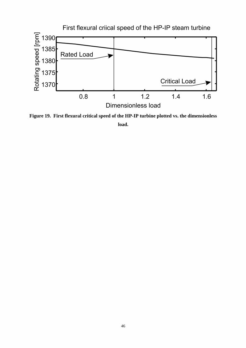
46
Figure 19. First flexural critical speed of the HP-IP turbine plotted vs. the dimensionless
load.
47
Figure 20. Instability factor associated with the eigenvalue n.3 plotted vs. the dimensionless
load.
48
Figure 21. 1X filtered journal orbits measured at bearings #1 and #2 few minutes before an
instability onset.
49
HP turbine IP turbine
L
Figure 22. Sketch of stiffness change on HP turbine.
50
0.8 1 1.2 1.4 1.6 1.8 2 2.2 2.41300
1350
1400
1450
Dimensionless Load
Rot
atio
nal s
peed
[rpm
] Third flexural critical speed vs. Load
Original HP-IP turbineModified HP-IP turbine
Figure 23. Third flexural critical speed plotted vs. the dimensionless load, after flexural
stiffness changes of the HP-IP turbine.
51
0.8 1 1.2 1.4 1.6 1.8 2 2.2 2.40.8
0.9
1
1.1
Dimensionless Load
Inst
abili
ty F
acto
r
Instability Factor vs. Load
Original HP-IP turbineModified HP-IP turbine
Figure 24. Instability factor associated with the eigenvalue n.3 plotted vs. the dimensionless
load, after flexural stiffness changes of the HP-IP turbine.
52
Shock and Vibration MANUSCRIPT 09-82 "Analysis of the Instability Phenomena Caused by Steam in High-pressure Turbines" By Paolo Pennacchi and Andrea Vania This document addresses step by step the comments made by the reviewers. Courier font is used for reviewer’s comments, Times for our answers and Times Italic for the modifications in the text. The manuscript contains highlighted modifications and additional parts, necessary to complain to reviewers’ comments. Revisions after reviewer 1 comments Mandatory Changes: 1. On page 6 the authors state: "That is, within a preliminary approximated study, the seal stiffness coefficients Kxy(Lj) associated with the load Lj are given by equation (8)". Please, include technical argumentation about such an approach based on the physics of the problem, i.e., steam flowing through gaps and the dependency of the stiffness coefficients on geometrical and operational conditions (megawatt load). This technique for the simulation of the dependence of the seal stiffness coefficients on the load is not based on a rigorous scientific approach, however this method is well established in design practice and was used also by the turbine manufacturer. In this regard it is important to consider that the study of the machine stability requires to perform a parametric analysis in order to investigate the sensitivity of the steam turbine stability margin to the seal stiffness hardening caused by the load rises. Within this study satisfactory results can be obtained also considering realistic estimates of the seal coefficients not necessarily evaluated by means of a very accurate analysis. In fact, it is important to emphasise that a rigorous evaluation of the seal stiffness coefficients would require to take into account also many parameters whose actual values are affected by a fairly high degree of uncertainty like hot machine alignment, seal clearances, local steam temperature and machine thermal expansions. Moreover, also the changes of the instantaneous position of the shaft inside the seal, caused by the machine vibrations, can generate significant fluctuations of the fluid-film forces (or: of the actual values of the seal coefficients in the neighborhood of the respective average value). In the case of not negligible levels of the machine vibrations, like those that can occur in the mid-span of the HP-IP turbine, a non-linear model should be used to study the machine stability. In the end, in the power units like that considered in this investigation the number of seals mounted on the HP-IP steam turbine is so large that only a 3D Finite Element Model of the shaft having a very large number of degrees of freedom would represent in detail the dynamic effects caused by the seals. Therefore, in common rotating machine models like that used in the present study only equivalent stiffness coefficients that simulate the effects of suitable groups of seals are considered. Nevertheless the practice shows that good results can be obtained also by means of these simplified models. Undoubtedly the evaluation of the mechanical characteristics of a single seal would require to apply a more rigorous approach. In this regard it is important to emphasize that the object of this paper is not to investigate the capabilities of accurate techniques for the evaluation of seal stiffness coefficients but to check the reliability of the results obtained by applying a standard procedure for the analysis of the stability margin of shaft-trains to the risk of the occurrence of steam-whip phenomena. Within this kind of study, based on a parametric analysis, the accuracy with which the seal stiffness coefficients included in the machine model have been defined is adequate in relation to the needs of the investigation. The satisfactory accordance between experimental evidences and numerical results confirmed this assumption. 2. Details about seal modeling and seal coefficient values have to be included in the paper, in order to allow the reproducibility of the theoretical results. As mentioned above equivalent stiffness coefficients that simulate the effects of suitable groups of seals are considered in the machine model. The values of these coefficients were evaluated by the turbine manufacturer considering the unit rated load. These data are confidential.

53
3. Details about the finite element model with data about element lengths, material and shaft cross-section properties, etc) have to be included in the paper in a table format, in order to allow the reproducibility of the theoretical results. Put figure 1 and figure 10 together and sequentially include a table with model data. Please see reference [8] and our paper on machine modelling. Unfortunately the details of the machine model cannot be included in the paper as they are covered by confidentiality restrictions. Anyhow, an additional figure, in which some basic geometrical parameters of the HP-IP and LP turbine are reported, has been included in the paper. Moreover, further information about the machine model are reported in two tables in which the basic parameters of the oil-film journal bearings of the two steam turbines have been summarized. 4. Details about the mechanical couplings between turbine and generator have to be included in a table format (model and coefficients), in order to allow the reproducibility of the theoretical results. See pag..4 of the original manuscript “… The shafts of the machine-train were coupled each other by means of rigid couplings.” In the case of a correct machine assembly no further data in addition to shaft and coupling diameters, as well as material properties, must be included in the model. 5. Details about the journal bearings properties , as geometry, lubrication fluid, modeling and coefficient values have to be included, in order to allow the reproducibility of the theoretical results. There are 6 bearings illustrated in figure 1. Please, include the information about those bearings in a table. Additional tables, in which the basic parameters of the oil-film journal bearings of the two steam turbines are summarized, have been included in the paper. Further tables contains the stiffness and damping coefficients of the oil-film journal bearings evaluated at the operating speed. 6. On page 8 the authors claim: "Therefore, the harmonic order of this vibration was 0.465. Although this order was rather close to 0.5X the supposition that this abnormal behavior was caused by an oil-whirl instability onset was discarded since the turbine shaft was mounted on tilting-pad journal bearings that, in general, are scarcely influenced by unstable phenomena except occasional events of pad-fluttering [27] [28]." The claim is not completely true. It is true that tilting-pad journal bearings (TPJB) are much more stable than the other types of hydrodynamic bearings, but instabilities with approx. 0.5X may occur depending on the operational conditions, i.e. low pre-load factor and low static load. It is thoroughly investigated, theoretically as well as experimentally, by different authors around the world (USA, China, Sweden and Norway). Please, see references [A1] [A2] [A3] [A4] [A5] put in a chronological way: [A1] Flack, R. D. & Zuck, C. J. (1988) "Experiments on the Stability of Two Flexible Rotor in Tilting-Pad Journal Bearing", Tribology Trans., Vol.31(2), 251-257. [A2] Zuck, C. J. & Flack, R. D. & Knight, J. D. and Barrett, L. E. (1988) "Experiments and Stability Predictions of Two Sets of Tilting-Pad Bearings on an Overhung Rotor", Tribology Trans., Vol.31(4), 468-475. [A3] Lie, Y. & You-Bai, Z. J. & Damou, Q. (1989) "Experiments on the Destabilizing Factors in Tilting-Pad Journal Bearings", Tribology International, Vol.22(5), 329-334. [A4] White, M. F. & Chan, S. H. (1992) "The Subsynchronous Dynamic
54
Behaviour of Tilting-Pad Journal Bearings", ASME Trans., Journal of Tribology, Vol.114(1), 167-173. [A5] Olsson, K. O. (1996) "Some Fundamental Aspects on the Dynamic Properties of Journal Bearings", Sixth International Conference on Vibrations in Rotating Machinery, IMechE, London, UK. 31-40. The flutter of the pad is an event that normally occurs at lower frequencies, as described in the literature [27] [28]. The authors know very well that tilting-pad journal bearings can be affected by pad-fluttering phenomena that generally cause sub-synchronous vibrations whose harmonic order is commonly ranging from 0.3X to 0.8X (anyway different orders can occur). In the original version of the paper the authors stated: “the assumption that this abnormal behaviour was caused by an oil-whirl instability onset was discarded since the turbine shaft was mounted on tilting-pad journal bearings that, in general, are scarcely influenced by unstable phenomena except occasional events of pad-fluttering”: this shows that the authors really considered the possibility that this kind of phenomenon could have caused the unstable sub-synchronous vibrations occasionally experienced in operating condition. However, on the basis of the results of further significant diagnostic investigation this assumption was discarded. Some months later the conclusion of the diagnostic analysis described in this paper, accordingly with the authors’ suggestion, the turbine manufacturer mounted a different type of seal at some stages of the HP turbine. This technical solution eliminated the occurrence of the unstable sub-synchronous vibrations. With regard to this it is important to emphasise that the order of the sub-synchronous vibrations caused by pad fluttering phenomena is significantly influenced by the mechanical and geometrical characteristics of the pads as well as by the stiffness and damping characteristics of the fluid-film that forms on each pad. Therefore, contrarily to fixed lobe journal bearings for which the unstable oil-whirl phenomena cause sub-synchronous vibrations whose harmonic order is ranging from 0.48X to 0.5X (except for the occurrence of oil-whip phenomena for which the sub-synchronous vibrations are synchronised with the first flexural critical speed of the shaft) the order of the sub-synchronous vibrations caused by pad fluttering phenomena is not necessarily close to 0.5X. Moreover, the physic phenomena that cause pad flattering are different from those that cause common oil-whirl (or whip) instabilities. A consequence of these different phenomena is just the generation of sub-synchronous vibrations whose harmonic order is not necessarily close to 0.5X nor to a flexural critical speed of the shaft. In the case study discussed in the present paper the order of the sub-synchronous vibrations (0.465X) was very close to a flexural critical speed of the HP-IP turbine that was associated with a “U” bending normal mode. This important aspect of the problem should be considered with great care. In fact, the destabilising forces associated with steam-whip phenomena excite a shaft normal mode that, in general, coincides with the first “U” bending mode of the steam-turbine. Since pad fluttering phenomena are commonly caused by a low bearing load, low pre-load factors can increase the risk of the occurrence of these unstable vibrations. At first the authors took into account the possibility that a pad-fluttering was the cause of the sub-synchronous vibrations that affected the turbine dynamic behaviour in operating condition, however after a detailed analysis of the monitoring data this diagnosis was discarded on the basis of clear symptoms that strengthened the assumption that the unstable vibrations were caused by a steam-whip phenomenon. This diagnosis was accepted also by the turbine manufacturer who decided to substitute the some original seals mounted on the first stages of the HP turbine with different seals equipped with tip swirl breakers. This corrective action eliminated the occurrence of the unstable sub-synchronous vibrations. The experimental evidence confirmed that the cause of the problem was the generation of steam-whip phenomena. With regard to this it is important to emphasise that the unstable sub-synchronous vibrations appeared at the end of the first load rise carried out after a cold start-up of the unit. That is the abnormal vibrations occurred when the machine was subjected to a significant heating. It is well known that high megawatt loads increase the risk of occurrence of steam-whip phenomena since this operating condition causes a seal stiffness hardening making it more likely the generation of unstable vibrations. Often these unstable sub-synchronous vibrations can be eliminated with a small reduction of the load. In the present case study the unstable vibrations occurred only when approaching the rated load and in thermal transient conditions, that is these events coincided with changes of the machine alignment conditions. Likely, the consequent changes of the seal clearances caused an abnormal stiffness hardening
55
in some groups of seals. This generated the conditions for the occurrence of unstable vibrations. The corresponding ideal model of the rotating machine that simulates the dynamic behaviour in this operating condition is characterised by an eigenvalue whose real part is positive while the imaginary part coincides with one of the lowest flexural critical speeds of the HP-IP turbine associated with a “U” bending mode. This causes the occurrence of expansive vibrations whose harmonic order coincides with the above mentioned flexural critical speed of the turbine shaft. In the present case this order was 0.465X. The assumption that the sub-synchronous unstable vibrations were caused by a steam-whip phenomenon was confirmed by some evidences pointed out by the analysis of the monitoring data. In fact, the experimental centreline curves of the HP-IP turbine journals were consistent with the characteristics of bearings #1 and #2 while the average journal position measured at the same supports, in operating condition, during the machine heating caused by the first load rise carried out at the end of the machine runup showed only minor changes. When the unit approached the rated load the overall amplitude of the HP-IP turbine vibrations showed a sharp significant peak caused by the appearance of instability phenomena that were timely suppressed making a small reduction in the load. The gap voltage measured in the neighborhood of these events showed only negligible changes of the average journal position inside bearings #1 and #2, therefore it is possible to state that the small reduction of few tens of megawatts of the load did not cause significant changes in the bearing loads although they were sufficient to immediately extinguish the unstable vibrations. These experimental evidences confirm that the sub-synchronous vibrations were not caused by pad-fluttering phenomenon as only significant changes of bearing loads, associated with important changes of the average journal position, would have been able to extinguish the instability phenomena. Conversely, even small changes of the steam characteristics can cause a suitable reduction of the seal stiffness coefficients and the consequent suppression of the abnormal dynamic behaviour of the steam turbine. 7. Analyzing figure 11, it seems that the two flexural modes of the train at 1437 rpm and 1497 rpm are completely dominated by the HP-IP steam turbine. How much the stiffness of the mechanical coupling between HP-IP turbine and LP-turbine influences such flexural modes? Could an increase of megawatt together with the influence of the coupling between HP-IP turbine and LP turbine generate a condition of "low static load" at the tilting-pad bearings that combined with a low pre-load factor of the bearings would generate instabilities on the HP-IP turbine, as of the type described in [A1] to [A5] and also similar to those presented by the authors, namely 0.5X? As said above common rigid coupling connected the HP-IP turbine to the LP turbine and the LP turbine to the generator. An additional Bode plot that illustrates the 1X transient vibrations measured at bearings #3 and #4 has been included in the paper to show the different dynamic behaviour of the LP turbine with respect to that of the HP-IP turbine. The passing through the first balance resonance of the HP-IP turbine caused an evident amplification of the 1X shaft vibrations measured at bearing #2 while negligible dynamic effects were noticed in the respective 1X vibrations measured at both journal bearings of the LP turbine. With regard to this it is necessary to consider that the shaft of the HP-IP turbine is rather slim (weight: 223 kN, bearing span: 6413 mm, overall length: 8691 mm) while the LP turbine has different geometrical and mechanical characteristics (weight: 461 kN, bearing span: 5420 mm, overall length: 8636 mm). Moreover, the distance between the adjacent supports #2 and #3 is rather long (3151 mm) with respect to the bearing spans of both steam turbines. In the end, the average diameter of this portion of the shaft-train was rather small: 360 mm. Therefore it is not surprising that in the rotational speed range from 1250 rpm to 1650 rpm the dynamic response of the shaft-train was dominated by the first balance resonance of the HP-IP turbine. 8. The experimental orbits presented in figures 6 and 7 have be plotted, illustrating the center of the bearing housing. In that way, the position of the shaft center into the bearing housing can be evaluated with respect to static loading and the hypothesis of instability coming from the bearings with low pre-load factors can totally put away or confirmed. The center line curve of the journal during runup has been added in a figure. This figure presents the information requested by the reviewer. 9. On page 12 the authors claim that "Therefore, the increase of the flexural stiffness caused by even a small increase of the average
56
diameter of the shaft can be sufficient to significantly reduce the sensitivity of the turbine dynamic behavior to steam-whip instability phenomena." Nevertheless, such a change will probably couple the dynamics of the whole train. Have the authors done any kind of simulation to evaluate the dynamics of the new system (turbine with new diameter)? How will the stability margins and damping factors of the modified system behave? It would be interesting to include such an analysis in the paper. It would be very useful for the technical community. The results of the required analysis have been enclosed in the paper in detail. In particular, the analysis performed by means of MAC shows that the increase of the shaft diameter does not change in a meaningful way the shape of the normal mode associated to the first critical speed. Minor Changes: 10. On page 3, page 7 and page 8 the authors repeat themselves 3 times about the possibility of using manuscript information to optimize the machine design and to adjust some process parameters of the train. Please, eliminate the redundant information. It was just emphasis, we deleted the repetitions. 11. On page 4, if the authors write [G(Ù)], they should also write [C(Ù)] and [K(Ù)]. Stiffness and damping matrices are also depending on the angular velocity Ù. The authors should choose between Ù [G], [C] and [K] or [G(Ù)], [C(Ù)] and [K(Ù)]. Done. Revisions after reviewer 2 comments The paper brings an interesting discussion about rotor dynamic stability analysis, although there is a lack of technical information related to new aspects of the system modeling and stability analysis procedure. Based on the information given in the paper, it is not clear the novelty with respect to previous research presented, for instance, by Musynska, Childs and Capone. Certainly, there is a significant contribution besides the real plant application, which deserves to be highlighted in the paper. Several parts of the paper have been changed and it is highlighted that the original contribution is in the accurate modeling that allows studying in a successful way the real plant application.
Related Documents